
27-OMRON-S8JC-Z
7
1 New Product Switch Mode Power Supply S8JC-Z (15/35/50/100/150/350-W Models) Economical Power Supply • Mount to DIN Rails for models with ratings of 15 to 350 W • Protection against overcurrents and overvoltages. Note: Refer to Safety Precautions on page 7. Model Number Structure Model Number Legend Note: Not all combinations are possible. Refer to List of Models in Ordering Information on page 1. 1. Power Ratings 015: 15 W 035: 35 W 050: 50 W 100: 100 W 150: 150 W 350: 350 W 2. Output Voltage 05: 5 V 12: 12 V 24: 24 V 3. Configuration (15/35/50/100/150 W model) C: Covered 4. Configuration/mounting None: Bottom-mounting D: DIN Rail-mounting Ordering Information List of Models Note: For details on normal stock models, contact your nearest OMRON representative. 1 2 34 S8JC-Z@@@@@@@ Configuration Input voltage Power ratings Output voltage (VDC) Output current Model Covered Power Supplies Bottom-mounting 200 to 240 VAC 15 W 5 V 3.0 A S8JC-Z01505C 12 V 1.3 A S8JC-Z01512C 24 V 0.7 A S8JC-Z01524C 35 W 5 V 7.0 A S8JC-Z03505C 12 V 3.0 A S8JC-Z03512C 24 V 1.5 A S8JC-Z03524C 50 W 24 V 2.1 A S8JC-Z05024C 100 W 24 V 4.5 A S8JC-Z10024C 150 W 24 V 6.5 A S8JC-Z15024C 350 W 24 V 14.6 A S8JC-Z35024C DIN Rail-mounting 15 W 5 V 3.0 A S8JC-Z01505CD 12 V 1.3 A S8JC-Z01512CD 24 V 0.7 A S8JC-Z01524CD 35 W 5 V 7.0 A S8JC-Z03505CD 12 V 3.0 A S8JC-Z03512CD 24 V 1.5 A S8JC-Z03524CD 50 W 24 V 2.1 A S8JC-Z05024CD 100 W 24 V 4.5 A S8JC-Z10024CD 150 W 24 V 6.5 A S8JC-Z15024CD 350 W 24 V 14.6 A S8JC-Z35024CD
-
Upload
tuansanleo -
Category
Documents
-
view
215 -
download
2
Transcript of 27-OMRON-S8JC-Z

1
New Product
Switch Mode Power SupplyS8JC-Z (15/35/50/100/150/350-W Models)
Economical Power Supply
• Mount to DIN Rails for models with ratings of 15 to 350 W
• Protection against overcurrents and overvoltages. Note: Refer to Safety Precautions on page 7.
Model Number StructureModel Number LegendNote: Not all combinations are possible. Refer to List of Models in Ordering Information on page 1.
1. Power Ratings015: 15 W035: 35 W050: 50 W100: 100 W150: 150 W350: 350 W
2. Output Voltage05: 5 V12: 12 V24: 24 V
3. Configuration (15/35/50/100/150 W model)C: Covered
4. Configuration/mountingNone: Bottom-mounting D: DIN Rail-mounting
Ordering InformationList of ModelsNote: For details on normal stock models, contact your nearest OMRON representative.
1 2 3 4S8JC-Z@@@@@@@
Configuration Input voltage Power ratings Output voltage (VDC) Output current Model
Covered Power Supplies
Bottom-mounting
200 to 240 VAC
15 W5 V 3.0 A S8JC-Z01505C
12 V 1.3 A S8JC-Z01512C24 V 0.7 A S8JC-Z01524C
35 W5 V 7.0 A S8JC-Z03505C
12 V 3.0 A S8JC-Z03512C24 V 1.5 A S8JC-Z03524C
50 W 24 V 2.1 A S8JC-Z05024C100 W 24 V 4.5 A S8JC-Z10024C150 W 24 V 6.5 A S8JC-Z15024C350 W 24 V 14.6 A S8JC-Z35024C
DIN Rail-mounting
15 W5 V 3.0 A S8JC-Z01505CD
12 V 1.3 A S8JC-Z01512CD24 V 0.7 A S8JC-Z01524CD
35 W5 V 7.0 A S8JC-Z03505CD
12 V 3.0 A S8JC-Z03512CD24 V 1.5 A S8JC-Z03524CD
50 W 24 V 2.1 A S8JC-Z05024CD100 W 24 V 4.5 A S8JC-Z10024CD150 W 24 V 6.5 A S8JC-Z15024CD350 W 24 V 14.6 A S8JC-Z35024CD
user
新建印章

S8JC-Z
2
Ratings, Characteristics, and Functions15-/35-/50-W Models
100-/150-/350-W Models
Note: 1. Unless otherwise specified, all parameters are measured with a 230-VAC input, at the rated load, and at an ambient temperature of 25°C.2. Ripple and noise are measured at a bandwidth of 20 MHz.3. Refer to the dimensional diagrams for details on DIN Rail-mounting Models (excluding terminal blocks and DIN Rail products).
Item Power ratings 15 W 35 W 50 W
Output
Output voltage (VDC) 5 V 12 V 24 V 5 V 12 V 24 V 24 V
Output current 3.0 A 1.3 A 0.7 A 7.0 A 3.0 A 1.5 A 2.1 A
Voltage adjustment range (typical) −10% to 10%
Ripple (typical) 100 mV 100 mV 150 mV 100 mV
Startup time (typical) 300 ms
Hold time (typical) 50 ms 30 ms
Efficiency (typical) 74% 80% 75% 82% 84% 84%
Input
Voltage 200 to 240 VAC (185 to 264 VAC)
Frequency 50/60 Hz (47 to 63 Hz)
Current (typical) 0.22 A 0.5 A 0.6 A
Leakage current 1 mA max.
Inrush current (for a cold start at 25°C) (typical) 40 A
Additional functions
Overload protection 105% of rated load current, voltage drop, intermittent, automatic reset
Overvoltage protection Yes
Parallel operation No
Series operation No
Other
Ambient operating temperature Refer to the derating curve in Engineering Data on page 3 (with no icing or condensation)
Dielectric strength1.5 kVAC for 1 min. (between all inputs and outputs; detection current: 20 mA)1.5 kVAC for 1 min. (between all inputs and PE terminals; detection current: 20 mA)0.5 kVAC for 1 min. (between all outputs and PE terminals; detection current: 20 mA)
Vibration resistance 10 to 55 Hz, 0.26-mm single amplitude for 2h each in X, Y, and Z directions
Output indicator Yes (Color: Green)
Dimensions (W×H×D)Bottom-mounting model 36×97×80 mm 38×98×129 mm
DIN Rail-mounting model (See note 3.) 46×97×106 mm 46×98×155 mm
Weight (typical)Bottom-mounting model 190 g 280 g
DIN Rail-mounting model 360 g 450 g
Item Power ratings 100 W 150 W 350 W
Output
Output voltage (VDC) 24 V 24 V 24 V
Output current 4.5 A 6.5 A 14.6 A
Voltage adjustment range (typical) −10% to 10%
Ripple (typical) 100 mV 150 mV 200 mV
Startup time (typical) 300 ms
Hold time (typical) 50 ms 25 ms
Efficiency (typical) 86% 88% 84%
Input
Voltage 200 to 240 VAC (185 to 264 VAC)
Frequency 50/60 Hz (47 to 63 Hz)
Current (typical) 1.4 A 2.0 A 4.2 A
Leakage current 1 mA max.
Inrush current (for a cold start at 25°C) (typical) 40 A
Additional functions
Overload protection 105% of rated load current, voltage drop, intermittent, automatic reset
Overvoltage protection Yes
Parallel operation No
Series operation No
Other
Ambient operating temperature Refer to the derating curve in Engineering Data on page 3 (with no icing or condensation)
Dielectric strength1.5 kVAC for 1 min. (between all inputs and outputs; detection current: 20 mA)1.5 kVAC for 1 min. (between all inputs and PE terminals; detection current: 20 mA)0.5 kVAC for 1 min. (between all outputs and PE terminals; detection current: 20 mA)
Vibration resistance 10 to 55 Hz, 0.26-mm single amplitude for 2h each in X, Y, and Z directions
Output indicator Yes (Color: Green)
Dimensions (W×H×D)Bottom-mounting model 38×98×159 mm 50×98×159 mm 50×115×195 mm
DIN Rail-mounting model (See note 3.) 46×98×186 mm 52×98×186 mm 52×115×221 mm
Weight (typical)Bottom-mounting model 350 g 450 g 750 g
DIN Rail-mounting model 520 g 620 g 920 g
user
新建印章

S8JC-Z
3
Engineering DataDerating Curves
Note: 1. Internal parts may occasionally deteriorate or be damaged. Do not use the Power Supply in areas outside the derating curve (i.e., the area shown by shading A in the above graph).
2. If there is a derating problem, use forced air-cooling.
Terminal Arrangement
Load
rat
e (%
)
Ambient Temperature (°C)
-20 -10 0 10 20 30 40 50 60 70
120
100
80
60
40
20
0
A
15-/35-/50-W Models 100-/150-/350-W Models
Note: The S8JC-Z05024C is shown above. Note: The S8JC-Z10024C is shown above.
AC(L)
AC(N)
−V
+V
AC(L)
AC(N)
−V
+V
−V
+V
user
新建印章

S8JC-Z
4
Dimensions (Unit: mm)
Bottom-mounting Models
9.5
5.5
4.2570.5±0.5
65±0
.58 97±1
3.5
79.5±1
36±1
30.5
4.517
.5
18 54±0.5
24
75±1
4
3.5 dia.
4 dia.
Two, M3(Depth 2 mm max.)
45.5
35±0.520.5
S8JC-Z015@@C (15 W)
Note: The screws must not protrude more than 2 mm inside the Power Supply when screw holes provided on the chassis are used. If the dimensions are not correct, the Power Supply may be damaged.
Panel mounting holes dimensions
Surface screw mounting
SideMounting
BottomMounting
Two, M3
59.5
±0.5
70.5±0.5
Two, M3
70.5±0.5
6.5±
0.5
9.5
5.5
4.5
33±0
.5
78
8
98.3
±1
129±1
38±1
6.5
2919
.5
32 77±0.5
18±0
.510
.5
15.5
13
4 dia.
4 dia.
Three, M3(Depth 2 mm max.)
34
Panel mounting holes dimensions
Surface screw mounting
SideMounting
BottomMounting
Two, M3
85.5
±0.5
122.5±0.5
Three, M3 13±0
.5
120±0.5
S8JC-Z035@@C (35 W)S8JC-Z05024C (50 W)
9.5
4.5
6
22 120±0.5
80±0
.58.
7
8
159±1
97.6
±1
38±1
7
31.5
22
149.5±0.5
22 125±0.5
1313
±0.5
16.5
15±0
.5
Three, M3(Depth 2 mm max.)
4 dia.
4 dia.
Panel mounting holes dimensions
Surface screw mounting
SideMounting
BottomMounting
Two, M3
84±0
.5
152±0.5
Three, M3
15±0
.5
149.5±0.5
S8JC-Z10024C (100 W)
user
新建印章

S8JC-Z
5
9.5
6
4.5 22 120±0.5
8.7
80±0
.5
8
159±1
98
Seven, M3 screws Four, M3 screws
50±1
2013
2943
.5
7
22 125±0.5
149.5±0.5
17.5
26±0
.5
4 dia.
4 dia.
Three, M3(Depth 2 mm max.)
Panel mounting holes dimensions
Surface screw mounting
SideMounting
BottomMounting
Two, M3
84±0
.5
152±0.5
149.5±0.5
Three, M3 26±0
.5
S8JC-Z15024C (150 W)
9.5
8
194.8
115
50±1 (3)
30 140±0.5
1325
±0.5
Four, M3(Depth 2 mm max.)
145±0.5
80±0
.517
.2
32.8
(3)S8JC-Z35024C (350 W)
user
新建印章
S8JC-Z
6
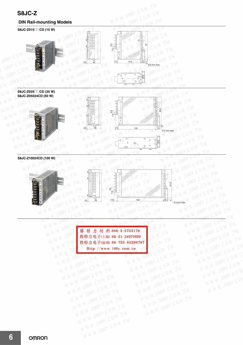
DIN Rail-mounting Models
9.5
7.8
97
79.5
5.5(10) (15.6)
9.5 mm max.46(3)
S8JC-Z015@@CD (15 W)
9.5
7.8
129
98.3
15
5
9.5 mm max.(3) 46 (10)
S8JC-Z035@@CD (35 W)S8JC-Z05024CD (50 W)
(10) 159 (16.1) 597
.6
9.5 mm max.(3) 46
9.5
7.8
S8JC-Z10024CD (100 W)
user
新建印章

S8JC-Z
7
Safety PrecautionsRefer to Safety Precautions for All Power Supplies.Precautions for Safe Use• Minor burns may occasionally occur. Do not touch the Product
while power is being supplied or immediately after power is turned OFF.
• Minor injury due to electric shock may occasionally occur. Do not touch the terminals while power is being supplied.
• Take adequate measures to ensure proper heat dissipation to increase the long-term reliability of the Product.
• Connect the ground completely. Electric shock or malfunction may occur if the ground is not connected completely.
• The service life of the fan is approximately 35,000 hours (at 25°C). The service life varies, however, depending on the ambient temperature or other surrounding environmental conditions such as dust. As a guide two years if it is used at an ambient temperature of 40°C. (For 350-W Models only.)
• The screws must not protrude more than 2 mm inside the Power Supply when screw holes provided on the chassis are used.
• Avoid places where the product is subjected to penetration of liquid, foreign substance, or corrosive gas (in particular, sulfide gas or ammonia gas).
9.5
7.8
159
97.5
5
9.5 mm max.51.5 (10) (16)
(3)
S8JC-Z15024CD (150 W)
9.5
7.8
194.8
115
5(16)(10)51.5
(3)(3)
9 mm max.
S8JC-Z35024CD (350 W)
user
新建印章