27”& 33” Automatic Floor Scrubber - Equipment Manuals · 27”& 33” Automatic Floor Scrubber...
45
27”& 33” Automatic Floor Scrubber Operator and Parts Manual t Model No.: 607045 - 27” 607043 - 33” BLUESTAR CUSTOMER SERVICE: 1-800-982-7658 FAX: 1 -800 -678 -4240 TECHNICAL SUPPORT: 1 -800 -522 -7839 EXT. 5356 TENNANT COMPANY 701 NORTH LILAC DRIVE MINNEAPOLIS, MN 55422 MAILING ADDRESS: TENNANT COMPANY P.O. BOX 1452 MINNEAPOLIS, MN 55440--1452 604621 Rev. 04 (04-2006) *604621*
-
Upload
truonghanh -
Category
Documents
-
view
226 -
download
2
Transcript of 27”& 33” Automatic Floor Scrubber - Equipment Manuals · 27”& 33” Automatic Floor Scrubber...
27”& 33” AutomaticFloor Scrubber
Operator and Parts Manual
t
Model No.:607045 - 27”607043 - 33”
BLUESTAR CUSTOMER SERVICE:1--800--982--7658
FAX: 1--800--678--4240
TECHNICAL SUPPORT:1--800--522--7839 EXT. 5356
TENNANT COMPANY701 NORTH LILAC DRIVEMINNEAPOLIS, MN 55422
MAILING ADDRESS:TENNANT COMPANYP.O. BOX 1452MINNEAPOLIS, MN 55440--1452
604621Rev. 04 (04-2006)
*604621*

OPERATION
27--inch & 33--inch Automatic Floor Scrubber (04--06)2
This manual is furnished with each new model.It provides necessary operation and maintenanceinstructions and an illustrated parts list.
Read this manual completely and understand themachine before operating or servicing it.
Use the illustrated Parts Lists to order parts. Beforeordering parts or supplies, be sure to have yourmachine model number and serial number handy.Parts and supplies may be ordered by phone or mailfrom any authorized parts and service center,distributor or from any of the manufacturer’ssubsidiaries.
This machine will provide excellent service. However,the best results will be obtained at minimum costs if:
S The machine is operated with reasonable care.
S The machine is maintained regularly - per themachine care instructions provided.
S The machine is maintained with manufacturersupplied or equivalent parts.
MACHINE DATA
Please fill out at time of installation for future reference.
Model No.-
Install. Date -
Serial No.-
E 1998, 1999, 2004, 2006 Tennant Company Printed in U.S.A.
PROTECT THE ENVIRONMENTPlease dispose of packaging materials,old machine components such asbatteries, hazardous fluids such asantifreeze and oil, in a safeenvironmentally way according to yourlocal waste disposal regulations.
Always remember to recycle.
TABLE OF CONTENTS
SAFETY PRECAUTIONS 3. . . . . . . . . . . . . . . . . . . .
SAFETY LABEL 4. . . . . . . . . . . . . . . . . . . . . . . . . . . .
MACHINE COMPONENTS 5. . . . . . . . . . . . . . . . . . .
CONTROL PANEL SYMBOLS 5. . . . . . . . . . . . . . .
MACHINE INSTALLATION 6. . . . . . . . . . . . . . . . . . .UNCRATING MACHINE 6. . . . . . . . . . . . . . . . . .ATTACHING SQUEEGEE ASSEMBLY 6. . . . .INSTALLING BATTERIES 6. . . . . . . . . . . . . . . .
MACHINE SETUP 7. . . . . . . . . . . . . . . . . . . . . . . . . .PRE--OPERATION CHECKS 7. . . . . . . . . . . . . .INSTALLING BRUSH OR PAD DRIVERS 7. . .FILLING SOLUTION TANK 8. . . . . . . . . . . . . . .
MACHINE OPERATION 8. . . . . . . . . . . . . . . . . . . . .WHILE OPERATING MACHINE 9. . . . . . . . . . .CIRCUIT BREAKERS 10. . . . . . . . . . . . . . . . . . . .
DRAINING TANKS 10. . . . . . . . . . . . . . . . . . . . . . . . . .DRAINING RECOVERY TANK 10. . . . . . . . . . . .DRAINING SOLUTION TANK 10. . . . . . . . . . . . .
CHARGING BATTERIES 11. . . . . . . . . . . . . . . . . . . .
MACHINE MAINTENANCE 12. . . . . . . . . . . . . . . . . .DAILY MAINTENANCE 12. . . . . . . . . . . . . . . . . . .WEEKLY MAINTENANCE 12. . . . . . . . . . . . . . . .MONTHLY MAINTENANCE 12. . . . . . . . . . . . . . .QUARTERLY MAINTENANCE 12. . . . . . . . . . . .BATTERY MAINTENANCE 13. . . . . . . . . . . . . . .
DRIVE CHAIN MAINTENANCE 14. . . . . . . . . . .
TRANSPORTING MACHINE 14. . . . . . . . . . . . . . . . .
STORING MACHINE 14. . . . . . . . . . . . . . . . . . . . . . . .
RECOMMENDED STOCK ITEMS 14. . . . . . . . . . . . .
TROUBLE SHOOTING 15. . . . . . . . . . . . . . . . . . . . . .
SPECIFICATIONS 17. . . . . . . . . . . . . . . . . . . . . . . . . .
MACHINE DIMENSIONS 17. . . . . . . . . . . . . . . . . . . .
ELECTRICAL DIAGRAMS 18. . . . . . . . . . . . . . . . . . .
PARTS LIST 20. . . . . . . . . . . . . . . . . . . . . . . . . . . . . . .REPLACEMENT BRUSHES ANDPAD DRIVER GROUP 20. . . . . . . . . . . . . . . . . . .RECOVERY TANK GROUP 22. . . . . . . . . . . . . . .CHASSIS GROUP 24. . . . . . . . . . . . . . . . . . . . . . .DRIVE WHEEL GROUP 26. . . . . . . . . . . . . . . . . .CONTROL PANEL GROUP 28. . . . . . . . . . . . . . .CONTROL CONSOLE GROUP 30. . . . . . . . . . .PAD DRIVER GROUP 32. . . . . . . . . . . . . . . . . . .BRUSH LIFT GROUP 34. . . . . . . . . . . . . . . . . . . .SOLUTION CONTROL GROUP 36. . . . . . . . . . .ELECTRICAL GROUP 38. . . . . . . . . . . . . . . . . . .SKIRT GROUP 40. . . . . . . . . . . . . . . . . . . . . . . . . .SQUEEGEE CONTROL GROUP 42. . . . . . . . . .SQUEEGEE GROUP 44. . . . . . . . . . . . . . . . . . . .
OPERATION
27--inch & 33--inch Automatic Floor Scrubber (05--04) 3
SAFETY PRECAUTIONS
This machine is intended for commercial use. It isdesigned exclusively to scrub hard floors in anindoor environment and is not constructed for anyother use. Use only recommended pads, brushesand commercially available floor cleanersintended for machine application.
All operators must read, understand and practicethe following safety precautions.
The following warning alert symbol and the “FORSAFETY” heading are used throughout this manual asindicated in their description:
WARNING: To warn of hazards or unsafepractices which could result in severe personalinjury or death.
FOR SAFETY: To identify actions which must befollowed for safe operation of equipment.
Failure to follow these warnings may result in:personal injury, electrical shock, fire or explosion.
WARNING: Fire Or Explosion Hazard. NeverUse Flammable Liquids Or Operate Machine In OrNear Flammable Liquids, Vapors Or CombustibleDusts.
This machine is not equipped with explosionproof motors. The electric motors will spark uponstart up and during operation which could cause aflash fire or explosion if machine is used in anarea where flammable vapors/liquids orcombustible dusts are present.
WARNING: Fire Or Explosion Hazard. Do NotPick Up Flammable Materials Or Reactive Metals.
WARNING: Fire Or Explosion Hazard.Batteries Emit Hydrogen Gas. Keep Sparks AndOpen Flame Away. Keep Battery CompartmentOpen When Charging.
WARNING: Electrical Hazard. DisconnectBattery Cables Before Servicing Machine.
The following information signals potentiallydangerous conditions to the operator orequipment:
FOR SAFETY:
1. Do not operate machine:-- With flammable liquids or near flammable
vapors as an explosion or flash fire mayoccur.
-- Unless trained and authorized.-- Unless operation manual is read and
understood.-- If not in proper operating condition.
2. Before starting machine:-- Make sure all safety devices are in place
and operate properly.
3. When using machine:-- Go slow on inclines and slippery surfaces.-- Wear no--slip shoes.-- Use care when reversing machine.-- Report machine damage or faulty
operation immediately.-- Never allow children to play on or around.-- Follow mixing and handling instructions
on chemical containers.
4. Before leaving or servicing machine:-- Stop on level surface.-- Turn off machine.
5. When servicing machine:-- Avoid moving parts. Do not wear loose
jackets, shirts, or sleeves.-- Block machine tires before jacking up.-- Use hoist or jack that will support the
weight of the machine.-- Wear eye and ear protection when using
pressurized air or water.-- Disconnect battery connections before
working on machine.-- Wear protective gloves and safety glasses
when handling batteries or battery cables.-- Avoid contact with battery acid.-- Use manufacturer supplied or approved
replacement parts.-- All repairs must be performed by a
qualified service person.-- Do not modify the machine from its
original design.
OPERATION
27--inch & 33--inch Automatic Floor Scrubber (04--06)4
6. When transporting machine:-- Turn machine off.-- Get assistance when lifting machine.-- Do not lift machine when batteries are
installed.
-- Use a recommended ramp whenloading/unloading into/off truck or trailer.
-- Use tie--down straps to secure machine totruck or trailer.
SAFETY LABEL
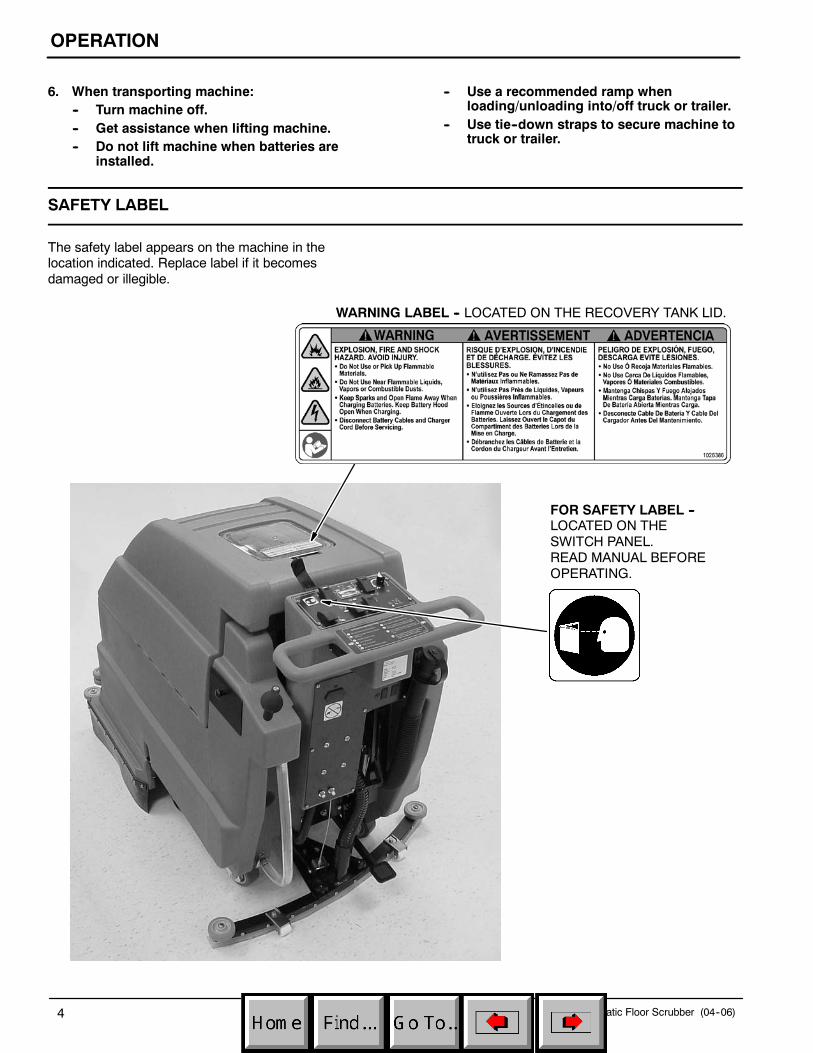
The safety label appears on the machine in thelocation indicated. Replace label if it becomesdamaged or illegible.
WARNING LABEL -- LOCATED ON THE RECOVERY TANK LID.
FOR SAFETY LABEL --LOCATED ON THESWITCH PANEL.READ MANUAL BEFOREOPERATING.
OPERATION
27--inch & 33--inch Automatic Floor Scrubber (05--04) 5
MACHINE COMPONENTS
4
10
15
7
3
13
9
12
14
5
6
16 17
20
1
8
20
2
1918
212223
11
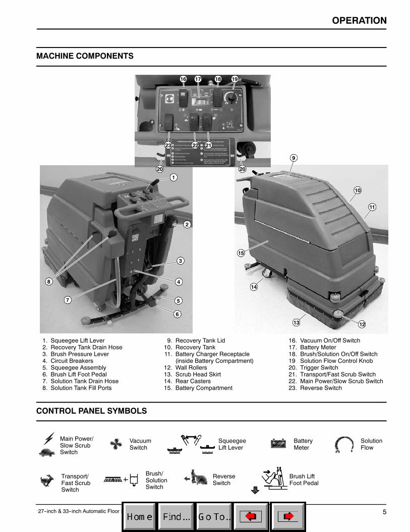
1. Squeegee Lift Lever2. Recovery Tank Drain Hose3. Brush Pressure Lever4. Circuit Breakers5. Squeegee Assembly6. Brush Lift Foot Pedal7. Solution Tank Drain Hose8. Solution Tank Fill Ports
9. Recovery Tank Lid10. Recovery Tank11. Battery Charger Receptacle
(inside Battery Compartment)12. Wall Rollers13. Scrub Head Skirt14. Rear Casters15. Battery Compartment
16. Vacuum On/Off Switch17. Battery Meter18. Brush/Solution On/Off Switch19 Solution Flow Control Knob20. Trigger Switch21. Transport/Fast Scrub Switch22. Main Power/Slow Scrub Switch23. Reverse Switch
CONTROL PANEL SYMBOLS
Main Power/Slow ScrubSwitch
VacuumSwitch
Transport/Fast ScrubSwitch
BatteryMeter
SolutionFlow
Brush/SolutionSwitch
ReverseSwitch
SqueegeeLift Lever
Brush LiftFoot Pedal

OPERATION
27--inch & 33--inch Automatic Floor Scrubber (05--04)6
MACHINE INSTALLATION
UNCRATING MACHINE
Carefully check carton for signs of damage. Reportdamages to carrier at once. Check carton contents toensure all accessories are included. Squeegee ispackaged with machine. Batteries, battery charger andpad drivers are packaged separately.
To uncrate your machine, remove shipping straps andraise scrub head. To raise scrub head, step downfirmly on the bottom brush lift foot pedal until pedallocks into the raised position. Carefully lift or use aramp to remove machine from pallet.
ATTENTION: Battery installation must beaccomplished after removing machine fromshipping crate.
ATTENTION: Do not roll machine off pallet,machine damage may occur.
ATTACHING SQUEEGEE ASSEMBLY
1. Slide squeegee lift lever to the right to raisesqueegee mount bracket (Figure 1).
FIG. 1
2. Loosen two thumb knobs on squeegee and slidesqueegee into slots at rear of squeegee mountbracket. Be certain that squeegee roller wheelsare toward the rear (Figure 2).
FIG. 2
3. Tighten thumb knobs securely.
INSTALLING BATTERIES
WARNING: Fire Or Explosion Hazard.Batteries Emit Hydrogen Gas. Keep Sparks AndOpen Flame Away. Keep Battery CompartmentOpen When Charging.
FOR SAFETY: When servicing machine, wearprotective gloves and safety glasses whenhandling batteries or battery cables. Avoid contactwith battery acid.
Recommended Battery Specifications:Four 6 volt, deep cycle, 305 amp hour batteries. PartNumber 606991. Maximum battery dimensions are178mm (7 in.) W x 308mm (12.13 in.) L x 356mm(14in.) H.
1. Turn all switches to the off (O) position.
2. Carefully hinge open recovery tank to accessbattery compartment. Remove loose batterycables from compartment (Figure 3).
FIG. 3
OPERATION
27--inch & 33--inch Automatic Floor Scrubber (05--04) 7
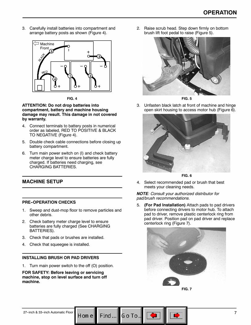
3. Carefully install batteries into compartment andarrange battery posts as shown (Figure 4).
MachineFront
1 2
3
4
5
FIG. 4
ATTENTION: Do not drop batteries intocompartment, battery and machine housingdamage may result. This damage in not coveredby warranty.
4. Connect terminals to battery posts in numericalorder as labeled, RED TO POSITIVE & BLACKTO NEGATIVE (Figure 4).
5. Double check cable connections before closing upbattery compartment.
6. Turn main power switch on (I) and check batterymeter charge level to ensure batteries are fullycharged. If batteries need charging, seeCHARGING BATTERIES.
MACHINE SETUP
PRE--OPERATION CHECKS
1. Sweep and dust-mop floor to remove particles andother debris.
2. Check battery meter charge level to ensurebatteries are fully charged (See CHARGINGBATTERIES).
3. Check that pads or brushes are installed.
4. Check that squeegee is installed.
INSTALLING BRUSH OR PAD DRIVERS
1. Turn main power switch to the off (O) position.
FOR SAFETY: Before leaving or servicingmachine, stop on level surface and turn offmachine.
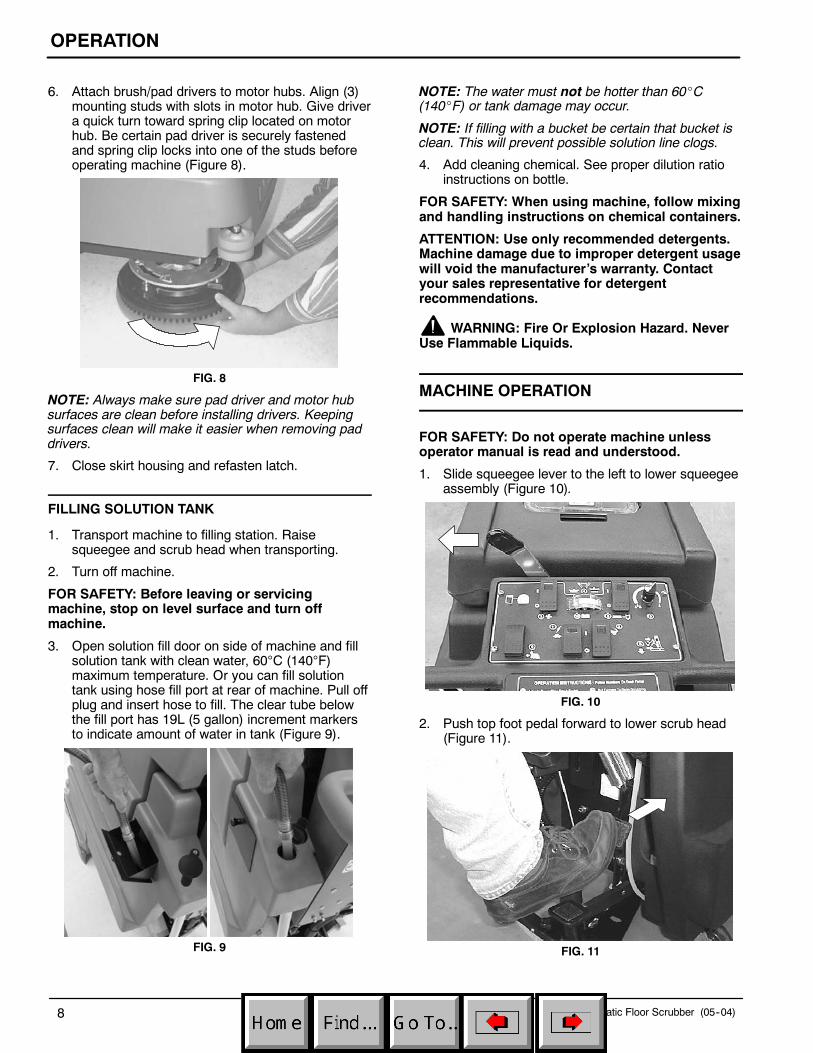
2. Raise scrub head. Step down firmly on bottombrush lift foot pedal to raise (Figure 5).
FIG. 5
3. Unfasten black latch at front of machine and hingeopen skirt housing to access motor hub (Figure 6).
FIG. 6
4. Select recommended pad or brush that bestmeets your cleaning needs.
NOTE: Consult your authorized distributor forpad/brush recommendations.
5. (For Pad Installation) Attach pads to pad driversbefore connecting drivers to motor hub. To attachpad to driver, remove plastic centerlock ring frompad driver. Position pad on pad driver and replacecenterlock ring (Figure 7).
FIG. 7
OPERATION
27--inch & 33--inch Automatic Floor Scrubber (05--04)8
6. Attach brush/pad drivers to motor hubs. Align (3)mounting studs with slots in motor hub. Give drivera quick turn toward spring clip located on motorhub. Be certain pad driver is securely fastenedand spring clip locks into one of the studs beforeoperating machine (Figure 8).
FIG. 8
NOTE: Always make sure pad driver and motor hubsurfaces are clean before installing drivers. Keepingsurfaces clean will make it easier when removing paddrivers.
7. Close skirt housing and refasten latch.
FILLING SOLUTION TANK
1. Transport machine to filling station. Raisesqueegee and scrub head when transporting.
2. Turn off machine.
FOR SAFETY: Before leaving or servicingmachine, stop on level surface and turn offmachine.
3. Open solution fill door on side of machine and fillsolution tank with clean water, 60°C (140°F)maximum temperature. Or you can fill solutiontank using hose fill port at rear of machine. Pull offplug and insert hose to fill. The clear tube belowthe fill port has 19L (5 gallon) increment markersto indicate amount of water in tank (Figure 9).
FIG. 9
NOTE: The water must not be hotter than 60_C(140_F) or tank damage may occur.
NOTE: If filling with a bucket be certain that bucket isclean. This will prevent possible solution line clogs.
4. Add cleaning chemical. See proper dilution ratioinstructions on bottle.
FOR SAFETY: When using machine, follow mixingand handling instructions on chemical containers.
ATTENTION: Use only recommended detergents.Machine damage due to improper detergent usagewill void the manufacturer’s warranty. Contactyour sales representative for detergentrecommendations.
WARNING: Fire Or Explosion Hazard. NeverUse Flammable Liquids.
MACHINE OPERATION
FOR SAFETY: Do not operate machine unlessoperator manual is read and understood.
1. Slide squeegee lever to the left to lower squeegeeassembly (Figure 10).
FIG. 10
2. Push top foot pedal forward to lower scrub head(Figure 11).
FIG. 11

OPERATION
27--inch & 33--inch Automatic Floor Scrubber (05--04) 9
3. Turn on main power, vacuum and brush/solutionswitches.
NOTE: The brush motors will start when triggers areactivated.
4. Pull triggers to begin scrubbing.
WARNING: Fire Or Explosion Hazard. Do NotPick Up Flammable Materials Or Reactive Metals.
5. Turn solution flow control knob to maximum for 30seconds, then adjust to desired flow (Figure 12).
FIG. 12
6. To operate in reverse, push and hold reverseswitch while pulling triggers (Figure 13).
FIG. 13
7. If additional scrubbing speed is desired, activatethe transport/fast scrub switch.
WHILE OPERATING MACHINE
WARNING: Fire Or Explosion Hazard. NeverOperate Machine In Or Near Flammable Liquids,Vapors Or Combustible Dusts.
FOR SAFETY: When using machine, go slow oninclines and slippery surfaces.
1. Observe amount of solution on floor and adjustsolution flow knob accordingly.
2. Periodically observe recovery tank for excessivefoam (look through clear lid). If excessive foamappears, pour a recommended foam controlsolution into recovery tank.
ATTENTION: Do not allow foam or water to enterrecovery tank float shut--off screen, vacuum motordamage will result. The float shut--off screen willnot keep foam out. Vacuum damage due to foamor water is not covered by warranty.
3. Change or turn pads over when worn.
4. If squeegee leaves streaks, raise and wipe bladeswith a cloth. Pre-sweep area to prevent streaking.
5. During brief stops, it’s not required to turn brushswitch off, the brush will automatically stop whentriggers are released.
6. Observe battery meter needle. When needledrops into the red zone, recharge batteries.
ATTENTION: Do not continue to run machinewhen battery meter needle is in the red zone,battery damage will result.
7. If additional scrubbing pressure is needed forsmall, heavily soiled areas, perform the following:a. Lower scrub head.b. Lift pad pressure lever to the locked position
(Figure 14).
NOTE: Scrub head must be lowered to allow padpressure lever to be lifted to the locked position. Lowerlever before raising scrub head.
FIG. 14
8. Periodically observe clear tube for remainingcleaning solution.
9. When solution tank runs dry, transport machine todraining area (See DRAINING TANKS).

OPERATION
27--inch & 33--inch Automatic Floor Scrubber (05--04)10
CIRCUIT BREAKERS
The machine is equipped with (4) circuit breakers toprotect motors from damage. If circuit breakers shouldtrip, they cannot be reset immediately. Determinecause, allow motor to cool and then reset. The brushmotor circuit breakers (35A), located near chargerplug, will trip due to excessive overload on pad. Turnover or change pads if breakers should trip. The maincircuit breaker (10A) and vacuum/drive motor circuitbreaker (35A) are located at rear of machine(Figure 15).
FIG. 15
DRAINING TANKS
FOR SAFETY: Before leaving or servicingmachine, stop on level surface and turn offmachine.
DRAINING RECOVERY TANK
Recovery tank must be emptied prior to refillingsolution tank. To drain recovery tank, perform thefollowing steps:
ATTENTION: If recovery tank is not emptiedbetween fill--ups, foam or water will enter floatshut--off screen located in the recovery tank anddamage vacuum motor. Float shut--off screen willnot keep foam out. Vacuum damage due to foamor water is not covered by warranty.
1. Remove recovery tank drain hose from holder,position hose over floor drain and twist off cap.To completely drain recovery tank, hinge opentank sideways and flip up tank support stand torest tank on (Figure 16).
NOTE: If using a bucket to drain machine, do not usesame bucket for filling solution tank. This will preventpossible solution line clogs.
FIG. 16
2. Rinse out recovery tank after each use. This willprevent foul odor buildup. Use a hose to rinse outthe recovery tank. Be careful not to spray waterinto shut--off float screen.
3. Replace drain hose cap tightly after draining.
DRAINING SOLUTION TANK
1. Pull solution tank drain hose (clear hose) off hosebarb at rear of machine and drain solution intofloor drain or bucket (Figure 17).
FIG. 17
2. Rinse out solution tank with clean water after eachuse and flush out solution flow system. This willprevent clogging due to chemical buildup. Useclear hose to drain solution tank.
3. Reconnect clear hose to hose barb. Be certainhose is completely pushed onto hose barb.

OPERATION
27--inch & 33--inch Automatic Floor Scrubber (05--04) 11
CHARGING BATTERIES
NOTE: Recharge batteries ONLY after a total of 30minutes of use or more. This will prolong battery life.
The following charging instructions are intendedfor supplied 24V chargers only. Only use acharger with the following specifications toprevent battery damage.
CHARGER SPECIFICATIONS:
S OUTPUT VOLTAGE - 24 VOLTS
S OUTPUT CURRENT - 25 AMPS MAXIMUM
S AUTOMATIC SHUTOFF CIRCUIT
S FOR DEEP CYCLE BATTERY CHARGING
NOTE: For optimum machine operation, keepbatteries charged at all times. Never leave batteriesdischarged for lengthy periods.
WARNING: Fire Or Explosion Hazard.Batteries Emit Hydrogen Gas. Keep Sparks AndOpen Flame Away. Keep Battery CompartmentOpen When Charging.
FOR SAFETY: When servicing machine, wearprotective gloves and safety glasses whenhandling batteries or battery cables. Avoid contactwith battery acid.
1. Transport machine to a flat, dry surface in a well--ventilated area for charging.
2. Turn off all switches.
FOR SAFETY: Before leaving or servicingmachine, stop on level surface and turn offmachine.
3. Hinge open recovery tank to access batteries.Make sure recovery tank is empty before opening.
4. Before charging, check the fluid level (A) in eachbattery cell. If the battery plates (B) are exposed,add just enough distilled water to cover plates.DO NOT OVERFILL. Overfilled batteries canoverflow during charging due to fluid expansion.Replace cell caps before charging (Figure 18).
A
B
FIG. 18
5. With charger’s power supply cord unplugged,connect battery charger into machine as shown.Flip up hood support stand and rest hood on standto promote ventilation (Figure 19).
FIG. 19
6. Plug the charger’s power supply cord into agrounded wall outlet (Figure 20).
Grounded3 Hole Outlet
Ground Pin
FIG. 20
FOR SAFETY: Do not operate charger unless cordis properly grounded.
NOTE: Once charger is connected, machinebecomes inoperable.
7. The charger will automatically begin charging andshut off when fully charged.
8. When disconnecting charger, always unplugcharger from wall outlet first.
9. After charging, recheck the battery fluid level (A) ineach battery cell. The level should be 1 cm (3/8 in)from the bottom of sight tubes (B). Add distilledwater if needed. DO NOT OVERFILL (Figure 21).
AB
FIG. 21

OPERATION
27--inch & 33--inch Automatic Floor Scrubber (05--04)12
MACHINE MAINTENANCE
To keep machine in good working condition, simplyfollow daily, weekly and monthly maintenanceprocedures.
FOR SAFETY: Before leaving or servicingmachine, stop on level surface and turn offmachine.
FOR SAFETY: Electrical Hazard. DisconnectBattery Cables Before Servicing Machine.
DAILY MAINTENANCE(Every 4 Hours of Use)
1. Remove and clean pads or brushes. Never usesoiled pads when cleaning. Replace pads whenthey become loaded with residue.
2. Remove and rinse float shut-off screen, located inrecovery tank (Figure 22).
FIG. 22
3. Drain and rinse tanks thoroughly. Remove anyclogging debris in tank drain hole.
4. Raise squeegee and wipe it down with a dry cloth.Store squeegee in the up position to preventsqueegee damage.
5. Clean machine housing with a nonabrasive,non-solvent cleaner.
ATTENTION: Do not power spray or hose offmachine. Electrical component damage mayresult.
6. Recharge batteries if needed(See CHARGING BATTERIES).
WEEKLY MAINTENANCE(Every 20 Hours of Use)
1. Check fluid level in battery cells(See BATTERY MAINTENANCE).
2. Clean battery tops to prevent corrosion(See BATTERY MAINTENANCE).
3. Check for loose or corroded battery cables.
MONTHLY MAINTENANCE(Every 80 Hours of Use)
1. Hinge open right side skirt, remove filter bowl andclean screen. Be certain that solution tank isempty prior to removing filter bowl (Figure 23).
FIG. 23
2. Check drive chain for excess slack. If chain needstightening, see DRIVE CHAIN MAINTENANCE.
3. Lubricate chain with a water resistant grease.
4. Lubricate axle and caster grease fittings with awater resistant grease.
5. Lubricate all linkage pivot points with siliconespray then coat with a water resistant grease tomaintain smooth operation.
6. Check machine for water leaks and loose nuts andbolts.
QUARTERLY MAINTENANCE(Every 250 Hours of Use)
Inspect motors for carbon brush wear. Replacebrushes when worn to a length of 10mm (0.38 in.) orless. Contact an Authorized Service Center for carbonbrush inspection.
ATTENTION: Contact an Authorized ServiceCenter for machine repairs. Machine repairsperformed by other than an authorized person willvoid the warranty.
OPERATION
27--inch & 33--inch Automatic Floor Scrubber (05--04) 13
BATTERY MAINTENANCE
WARNING: Fire Or Explosion Hazard.Batteries Emit Hydrogen Gas. Keep Sparks AndOpen Flame Away. Keep Battery CompartmentOpen When Charging.
FOR SAFETY: When servicing machine, wearprotective gloves and safety glasses whenhandling batteries and battery cables. Avoidcontact with battery acid.
1. Always follow proper charging instructions(see CHARGING BATTERIES).
2. Check fluid level (A) in each battery cell. The fluidlevel should be 1 cm (3/8 in.) from the bottom ofsight tubes after charging. Add distilled water ifneeded. DO NOT OVERFILL. Overfilled batteriescan overflow during charging due to fluidexpansion (Figure 24).
A
FIG. 24
3. After charging batteries, measure the specificgravity in each battery cell using a hydrometer(Figure 25). This will determine the charge leveland condition of the batteries. If one or more ofthe battery cells test lower than the other batterycell (0.050 or more), the cell is damaged,shortened, or is about to fail.
NOTE: Do not take reading immediately after addingdistilled water. The water and acid must be thoroughlymixed in order for accurate reading.
FIG. 25
SPECIFIC GRAVITYat 27°C (80°F)
BATTERYCHARGE
1.265 100% CHARGED
1.223 75% CHARGED
1.185 50% CHARGED
1.148 25% CHARGED
1.110 DISCHARGED
NOTE: Add or subtract 0.004 gravity reading for each6_C (10_F) above or below 27_C (80_F).
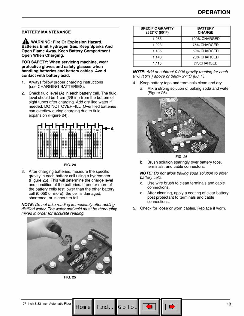
4. Keep battery tops and terminals clean and dry.a. Mix a strong solution of baking soda and water
(Figure 26).
FIG. 26
b. Brush solution sparingly over battery tops,terminals, and cable connectors.
NOTE: Do not allow baking soda solution to enterbattery cells.c. Use wire brush to clean terminals and cable
connections.d. After cleaning, apply a coating of clear battery
post protectant to terminals and cableconnections.
5. Check for loose or worn cables. Replace if worn.

OPERATION
27--inch & 33--inch Automatic Floor Scrubber (05--04)14
DRIVE CHAIN MAINTENANCE
FOR SAFETY: Before leaving or servicingmachine, stop on level surface and turn offmachine.
Inspect drive chain for proper tension. Chain shouldflex between 6.35mm (0.25 in.) and 12.7mm (0.50 in.)from center. If chain flexes more than 12.7mm(0.50 in.) chain should be tightened. To tighten chain,follow steps below:
1. From operators right side of machine, locate andloosen 4 motor mount bolts, do not remove bolts.
2. Loosen locking nut on tension bolt (Figure 27).
FIG. 27
3. Turn tension bolt clockwise until chain is properlyadjusted.
4. Retighten locking nut and 4 motor mount screws.
5. Lubricate chain with a water resistant oil.
TRANSPORTING MACHINE
When transporting machine by use of trailer or truck,be certain to follow tie--down procedures below:
FOR SAFETY: When using machine, go slow oninclines and slippery surfaces.
1. Remove squeegee from machine and raise brushhead. Leave pad or brush installed.
2. Load machine using a recommended loadingramp.
3. Position front of machine up against front of trailerof truck. Once machine is positioned, lower brushhead.
4. Place a block behind the drive wheel and the rearcasters.
5. Place tie--down straps over top of machine andsecure straps to floor. It may be necessary toinstall tie--down brackets to the floor of your traileror truck.
STORING MACHINE
1. Before storing machine, be certain to flush tanksand drain machine of all water.
2. Store machine in a dry area with squeegeeremoved and pad driver in the raised position.
3. Remove recovery tank lid to promote aircirculation.
4. When storing machine for short periods, raise paddriver and squeegee off floor to prevent damage.
ATTENTION: If storing machine in freezingtemperatures, be certain to drain machine of allwater. Damage due to freezing temperatures is notcovered by warranty.
ATTENTION: Do not expose machine to rain; storeindoors.
RECOMMENDED STOCK ITEMS
Refer to the Parts List section for recommended stockitems. Stock Items are clearly identified with a bulletpreceding the parts description. See example below:

OPERATION
27--inch & 33--inch Automatic Floor Scrubber (10--98) 15
TROUBLE SHOOTING
PROBLEM CAUSE SOLUTION
Machine does not operate. Batteries need charging. See CHARGING BATTERIES.
Faulty battery(s). Replace battery(s).
Loose battery cable. Tighten loose cable.
Improper battery connection. See INSTALLING BATTERIES.
Faulty main power switch Contact Service Center.
Main circuit breaker has tripped. Determine cause and reset circuitbreaker button.
Faulty trigger switch. Contact Service Center.
Brush motor does not operate. Brush circuit breaker has tripped. Clean or change to a less aggres-sive pad. Also, release pad pres-sure lever if it’s in the up position.Reset breaker button.
Loose wire connection. Contact Service Center.
Triggers not pulled. Pull triggers to activate brushes.
Faulty brush motor or wiring. Contact Service Center.
Worn carbon brushes. Contact Service Center.
Faulty solenoid. Contact Service Center.
Vacuum motor does not operate. Vacuum circuit breaker hastripped.
Remove obstruction and resetbreaker.
Faulty vacuum switch. Contact Service Center.
Faulty wiring. Contact Service Center.
Faulty vacuum motor. Contact Service Center.
Faulty solenoid. Contact Service Center.
Worn carbon brushes. Contact Service Center.
Short run time. Batteries not fully charged. Charge batteries.
Bad cell in one or more batteries. Replace battery.
Batteries need maintenance. See BATTERY MAINTENANCE.
Faulty charger. Replace battery charger.
Poor squeegee pick up. Full recovery tank. Empty recovery tank.
Clogged float shutoff screen. Remove screen and clean.
Clogged squeegee. Clean squeegee.
Worn squeegee blades. Replace squeegee blades.
Loose squeegee thumbscrews. Tighten thumbscrews.
Loose vacuum hose connectionsor hole in hose.
Push hose cuffs firmly on connec-tions. Replace hose if damaged.
Clogged vacuum hose. Remove clogged debris.
Worn recovery tank lid gasket. Replace gasket.

OPERATION
27--inch & 33--inch Automatic Floor Scrubber (10--98)16
TROUBLE SHOOTING --continued
PROBLEM CAUSE SOLUTION
Poor squeegee pick up. Drain hose plug is loose. Tighten drain plug.
Vacuum motor is loose. Contact Service Center.
Battery charge is low. Charge batteries. Do not runmachine when battery meter is inthe red zone.
Faulty vacuum motor. Contact Service Center.
Drive motor does not operate. Main circuit breaker has tripped. Determine cause and reset circuitbreaker.
Faulty main power switch. Contact Service Center.
Faulty solenoid. Contact Service Center.
Faulty wiring. Contact Service Center.
Faulty drive motor. Contact Service Center.
Worn carbon brushes. Contact Service Center.
Faulty resistor. Contact Service Center.
Little or no solution flow. Solution flow knob not activated. Turn knob to desired flow.
Clogged solution line or filter. Remove hose and blow com-pressed air through it. Flush solu-tion tank after each use.
Clogged solenoid valve. Remove valve and clean. Do notscratch or damage inside of valve.
Faulty solenoid valve. Contact Service Center.
Loose set screw on solution knob. Recalibrate solution flow and tight-en knob set screw.

OPERATION
27--inch & 33--inch Automatic Floor Scrubber (05--04) 17
SPECIFICATIONS
MODEL 27” Automatic Scrubber 33” Automatic Scrubber
LENGTH 1520mm (60 in.) 1520mm (60 in.)
WIDTH 740mm (29 in.) 890mm (35 in.)
HEIGHT 1090mm (43 in.) 1090mm (43 in.)
WEIGHT -- WITH BATTERIES 352Kg (760 lbs) 355Kg (765 lbs)
TANKS CAPACITY 98L (26 gal) 98L (26 gal)
SPEED CONTROL Two Speed Forward, One Speed Reverse Two Speed Forward, One Speed Reverse
CLEANING SPEED Maximun -- 1858 sq. m. (20,000 sq. ft) per hr.Slow Scrub Speed -- 35m (115 ft) per min.Transport/Fast Scrub Speed - 49m (160 ft) per min.
Maximun -- 2322 sq. m.(25,000 sq. ft) per hr.Slow Scrub Speed -- 35m (115 ft) per min.Transport/Fast Scrub Speed -- 49m (160 ft) per min.
CLEANING PATH WIDTH 680mm (27 in.) 830mm (33 in.)
PAD DIAMETER 2 -- 355mm (14 in.) 2 -- 430mm (17 in.)
SQUEEGEE WIDTH 860mm (34 in.) 1010mm (40 in.)
DRIVE MOTOR .5 h.p., 0--1560 rpm, 24V, 5A .5 h.p., 0--1560 rpm, 24V, 5A
BRUSH MOTOR 2 -- .75 h.p., 220 rpm, 24V, 20A, 550W 2 -- .75 h.p., 220 rpm, 24V, 20A, 550W
VACUUM MOTOR .75 h.p., 3--stage 5.7”, 24V, 21A, 550W .75 h.p., 3--stage 5.7”, 24V, 21A, 550W
WATER LIFT 1720mm (68 in.) 1720mm (68 in.)
BATTERIES 4--305A/hr, 6V deep cycle 4--305A/hr, 6V deep cycle
RUN TIME on full charge 4.76 Hours 4.76 Hours
DECIBEL RATING AT OPERA-TOR’S EAR, INDOORS ON TILE.
<70dB(A) <70dB(A)
MACHINE DIMENSIONS
740mm (29 in.) -- 27 in. Machine890mm (35 in.) -- 33 in. Machine 1520mm
(60 in.)
1090mm(43 in.)

ELECTRICAL DIAGRAMS
27--inch & 33--inch Automatic Floor Scrubber (04--06)18
WIRE DIAGRAM
BLK
WHT
RED
GRN
ORGGRN
YEL
70RED
BLK
18
13 BLKBLK
VACUUMSWITCH
BATTERYMETER
CHARGERPLUG
OPTIONALLOW VOLTAGEBRUSH MOTORINTERRUPT
CHARGERPLUGSAFETYSWITCH
--+
35 35
DRIVEMOTOR
VACUUMMOTOR
TIMERRELAY
L
YEL
17
20 GRN
15
20GRN10
GRN26
30 BLU
ORG
BLK 11
GRN 10
GRN 56
YEL 38
WHT60
BRUSH/SOLUTIONSWITCH
FAST
SLOW
16GRN
28ORG
11 BLK
56 GRN
9 BLK
BLK 9
50
RED
58RED MAIN
SWITCH
PNK 40
42RED
19BLK
3
BLK36 38
YEL YEL
BLK
12 GRN
48 ORG
3BLK
4828 26 ORG
12
GRN
8RED
6RED
14RED
18YEL
40PNK
21BLK36YEL
24
RED RED
5BLK
BLK
ESSWITCH
WHT60WHT34
BLKBLK
32 TAN
WANDSWITCH
BLK1
1 BLK
BLK
68
RED
27BLK
4RED
24RED
2468
2
RED
REDRED
RED
25 BLK
BLUBLU22
30
52 RED46RED
62
RED
(+)(+)BLK
29
BLK31
64
WHT
BLK
RED
3436
40
WHT
YEL
PNK
(+)
BLK
23
21
BLK
32
TAN
7
BLK
7
BLK
22
BLU
8
BLK
42RED
4RED
36YEL
40PNK
21BLK
RED 42
30
BLU
66
GRN
66
GRN
66
GRN
REVERSERESISTOR
LOW SPEEDRESISTOR
23 BLK3129
BLKBLK
TRAVELSPEEDSWITCH
21
44RED
RED
BLK
27
BLK
10AMP
35AMP
(4) 6 VOLTBATTERIES24 VDC
SOLUTIONSOLENOID
VACUUM/DRIVECIRCUITBREAKER
MAINCIRCUITBREAKER
DIRECTIONSWITCH
DRIVE
LEFTTRIGGERSWITCH
RIGHTTRIGGERSWITCH
OPTIONALKEY SWITCH
OPTIONALEMERGENCY
STOP
FLOATSWITCH
BLKBLKBLK
WHT
PNK
GRN
BLK
RED BLK
BRUSHMOTORCIRCUITBREAKER
RIGHT
MOTORCIRCUITBREAKER
PNK
RED
RELAY
14
23
LEFT BRUSHMOTOR
L
ESPUMP
WIRE HARNESS
CONNECTOR
VACUUM
BRUSHBRUSH
LEFT
RIGHT BRUSHMOTOR
+
--
+
--
+
--
+
--
ELECTRICAL DIAGRAMS
1927--inch & 33--inch Automatic Floor Scrubber (10--98)
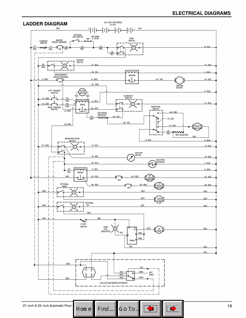
LADDER DIAGRAM
--24--RED
TIMER
--20--GRN
35A
LEFT TRIGGERSWITCH
RIGHT TRIGGERSWITCH
REV. RESISTOR
35A
35A
TANKFULL
INDICATOR
LOW SPEEDRESISTOR
FLOATSWITCH
G
214 3
+ --
G
G
G
G
G
G
--RED--
--WHT----BLK-- --GRN--
--ORG--
--YEL--
RED BLK
--4--RED
--14--RED
--44--RED
--58--RED
--50--RED
--9-- BLK
--17-- BLK
--1-- BLK
--23-- BLK
--5-- BLK
--11-- BLK
--3-- BLK
--13-- BLK
--15-- BLK
--7-- BLK
--5-- BLK
--31-- BLK
--29-- BLK
BLK
BLK
BLK
BLK
BLK
BLK
--17-- BLK
--18-- YEL
--6-- RED--2-- RED
--12-- GRN
--16-- GRN
--48--ORG--28--ORG
--8-- RED
BLU BLK
--5-- BLK
--60-- WHT
--34--WHT
--26--ORG
--38-- YEL
--36-- YEL
--40-- PNK
--19-- BLK
--21-- BLK
--42--RED
--3-- BLK
BLK
--13-- BLK
--70-- RED
--22-- BLU
--5-- BLK
--52-- RED
--46-- RED
--64-- RED
--62-- RED
BLK
WHT
BLK
--30--BLU
RED
GRN
GRN
GRN RED
BLK
BLK
PNK
PNK
PNK
WHT
RED
GRN
--32-- TAN
--56-- GRN
--10-- GRN
VACUUM
SOLUTIONSOLENOID
HOURMETER
NOTUSED
LOW VOLTAGE BRUSH INTERRUPT
MAINSWITCH
(4) 6 VOLT BATTERIES24 VDC
10A
MASTERCIRCUIT BREAKERCHARGER
SWITCH
VACUUMSWITCH
VACUUMMOTOR
SLOW/FASTSWITCH
DRIVE
DRIVEMOTOR
BRUSH/SOLUTIONSWITCH
BATTERYMETER
BRUSH
RTBRUSHMOTOR
LTBRUSHMOTOR
OPTIONALWAND
OPTIONALES
ESPUMP
OPTIONALKEY SWITCH OPTIONAL
E--STOP
WANDPUMP
VACUUM/DRIVECIRCUIT BREAKER
DIRECTIONSWITCH

PARTS LIST
27--inch & 33--inch Automatic Floor Scrubber (05--04)20
REPLACEMENT BRUSHES AND PAD DRIVER GROUP
1
2
6
5
4
3

PARTS LIST
27--inch & 33--inch Automatic Floor Scrubber (05--04) 21
REPLACEMENT BRUSHES AND PAD DRIVER GROUP
REF PART # DESCRIPTION QTY.
∇ 1 240227 BRUSH, 14” POLY SCRUB (PK/2)(27” MACHINE)
1
240234 BRUSH, 14” NYLON GRIT (PK/2)(27” MACHINE)
1
240236 BRUSH, 14” DYNA SCRUB (PK/2)(27” MACHINE)
1
240243 BRUSH, 14” SCRUB/STRIP (PK/2)(27” MACHINE)
1
240230 BRUSH, 17” POLY SCRUB (PK/2)(33” MACHINE)
1
240235 BRUSH, 17” NYLON GRIT (PK/2)(33” MACHINE)
1
240237 BRUSH, 17” DYNA SCRUB (PK/2)(33” MACHINE)
1
240241 BRUSH, 17” SCRUB/STRIP (PK/2)(33” MACHINE)
1
Y 2 240238 LUGS, W/ SCREWS (PK/3) 2
∇ ASSEMBLY
Y INCLUDED IN ASSEMBLY
D RECOMMENDED STOCK ITEMS
REF PART # DESCRIPTION QTY.
∇ 3 240232 DASM, 14” PAD DRIVER (PK/2)(27” MACHINE)
1
240233 DASM, 17” PAD DRIVER (PK/2)(33” MACHINE)
1
Y 4 240238 LUGS, W/ SCREWS (PK/3) 2
Y 5 100106 PLATE, PAD DRIVER BASE 2
Y 6 100107 DRING, PAD RETAINER SNAP--IN 2
PARTS LIST
27--inch & 33--inch Automatic Floor Scrubber (04--06)22
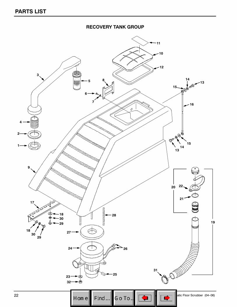
RECOVERY TANK GROUP
11
10
12
1513
16
14
1413
28
27
24 26
2523
32
31
17
2930
18
9
5
2
1
4
3
6
7
8
15
19293018
20
21
22

PARTS LIST
27--inch & 33--inch Automatic Floor Scrubber (04--06) 23
RECOVERY TANK GROUP
REF PART # DESCRIPTION QTY.
1 210240 NUT, FLANGED 1--1/2 FPT 1
2 101714 DGASKET, WASTE AIR CHAMBER 1
∇ 3 100162 ASM STANDPIPE W/NIPPLE 1
Y 4 606088 FITTING, 1--1/2” NIPPLE CPVC 1
5 180613 DFLOAT, SHUT--OFF 1
6 140872 SCREW, #6X3/8 PANPHL 4
7 1009168 WASHER, FLAT, 0.17B 0.75D .04 SS 4
8 630056 STRAP, TANK COVER RETAINING 1
9 607197 TANK, RECOVERY, NAVY BLUE 1
∇ 10 613716 ASSEMBLY, LID & LABEL 1
Y 11 1026386 LABEL, WARNING 1
Y 12 630367 DGASKET, REC. TANK COVER 1
13 16931 SCREW, M8X1.25X20 HEXHD 2
14 140015 WASHER, LOCK, SPLIT, 0.31 SS 2
15 140027 WASHER, FLAT, 0.35B 0.75D .04 SS 2
16 140960 DCABLE, REC TANK SUPPORT 1
∇ ASSEMBLY
Y INCLUDED IN ASSEMBLY
D RECOMMENDED STOCK ITEMS
REF PART # DESCRIPTION QTY.
17 230938 DHINGE, REC TANK 1
18 140000 WASHER, FLAT, 0.28B 0.62D .04 SS 11
∇ 19 1010143 DASSEMBLY, DRAIN HOSE 1
Y∇20 1008639 DASSEMBLY, CAP, DRAIN HOSE 1
Y21 1008637 DO--RING 1
Y22 1019563 DSTRAP, DRAIN CAP 1
23 140000 WASHER, FLAT, 0.28B 0.62D .04 SS 3
∇ 24 130477 DMOTOR, VAC 5.7 3S 24V 1
Y 25 190163 DBRUSH, CARBON 2/PK 1
26 130096 CONNECTOR ASSY, BLADE,MALE, .25
2
27 626092 DGASKET, VAC MOTOR 1
28 140353 SCREW, M6X1.0X108 STUD 3
29 363503 SCREW, M6X1.0X12 PANHD 11
30 140052 WASHER, 1/4 LOCK 11
31 140308 CLAMP, HOSE 1--5/16 TO 2--1/4 1
32 08712 NUT, HEX, LOCK, M6 X 1.00 SS, NL 3

PARTS LIST
27--inch & 33--inch Automatic Floor Scrubber (05--04)24
CHASSIS GROUP
1
2
3
20
1416
15
13
1112
6
97
810
54
14
21
17
19
18

PARTS LIST
27--inch & 33--inch Automatic Floor Scrubber (05--04) 25
CHASSIS GROUP
REF PART # DESCRIPTION QTY.
1 130367 CABLE, BATTERY 15” BLK X 6 GA. 3
2 606991 BATTERY, 6V 4
3 100707 PLATE, BATTERY SUPPORT 1
4 607195 TANK, SOLUTION, NAVY BLUE 1
5 120567 DECAL, WARNING BATTERYDIAGRAM
1
6 578237000 SCREW M8X1.25X18 HXHDCP 1
7 140015 WASHER, LOCK, SPLIT, 0.31 SS 1
8 140027 WASHER, FLAT, 0.35B 0.75D .04 SS 1
9 611418 SLEEVE, .437D, .315B, .14L 1
10 230925 SUPPORT, RECOVERY TANK 1
11 1018155 SCREW, PAN, M5X0.8X16 SS,TCUT
1
12 01683 WASHER, FLAT #10 SS 1
∇ ASSEMBLY
Y INCLUDED IN ASSEMBLY
REF PART # DESCRIPTION QTY.
13 1012965 CAP, PORT, SOLUTION FILL 1
14 150529 FITTING, 3/4M X 3/4H BARB 2
15 600796 HOSE, DRAIN W/LEVELINDICATOR
1
16 608915 CLAMP, HOSE 1.03--1.09 1
∇ 613196 ASSEMBLY, REAR FILL 1
Y 17 1001438 BRACKET, REAR FILL 1
Y 18 601424 KNOB 1
Y 19 140195 SCREW, TRS, .25--20 X 0.50 PHLSEM
1
20 130871 CHARGER, 24VDC 25AMP120AC/60HZ
1
21 607082 DECAL, BLUESTAR LOGO 1

PARTS LIST
27--inch & 33--inch Automatic Floor Scrubber (05--04)26
DRIVE WHEEL GROUP
1
2
4
8
9
1011
12
1413
15
16
17
18
2021
19
22
23
25
26
2724
2930
31
32
35
34
33
28
47
45
44
46
48
4342
39
4140
38
36
7
37
5
6
2835
11
3

PARTS LIST
27--inch & 33--inch Automatic Floor Scrubber (04--06) 27
DRIVE WHEEL GROUP
REF PART # DESCRIPTION QTY.
1 600349 SCREW, 5/16--18X2--3/4 HEXHD 2
2 140015 WASHER, LOCK, SPLIT, 0.31 SS 2
3 611048 SCREW, HEX, .38--16 X 1.25 SS 1
4 1014918 WHEEL, 3.0D 1.00W, RUBBER 4
5 140028 WASHER, FLAT, 0.42B 1.00D .05 SS 2
6 140333 WASHER, M10 LOCK 2
7 140276 SCREW, M10X1.5X16 HEXHD 2
8 1016124 CHASSIS, WELDMENT 1
9 230655 BRACKET, DRIVE MOTORTENSION
1
10 69225 SCREW, HEX, .38--16 X 1.00 SS 3
11 140017 WASHER, LOCK, SPLIT, 0.38 SS 3
12 140028 WASHER, FLAT, 0.42B 1.00D .05 SS 3
13 130713 DRESISTOR, 100 WATT .9 OHM 2
14 140519 NUT, HEX LOCK #10--24 KEP SS 8
15 140900 SCREW, #10--24X3/4 TRSPHL 4
16 140024 WASHER, LOCK, 0.50 SS 2
17 140352 SCREW, M12X1.75X25 HEXHD 2
18 103002 DCASTER, 4” SWIVEL 2
19 140036 WASHER, 3/8 FLAT 8
20 140333 WASHER, M10 LOCK 8
21 140285 NUT, M10X1.5 HEX 8
22 140859 SCREW, SET, .25--20X0.25 CUP PT 1
23 240087 SPROCKET, #40--12 1
∇ ASSEMBLY
Y INCLUDED IN ASSEMBLY
D RECOMMENDED STOCK ITEMS
REF PART # DESCRIPTION QTY.
∇ 24 613421 DMOTOR, DRIVE 24V 1
Y 25 140632 KEY, .25 X .25 X 1.00L 1
Y 26 613424 DCAP, CARBON BRUSH 4
Y 27 130508 DCARBON BRUSH 4
28 140525 NUT, HEX, STD, .38--16 SS 5
29 611048 SCREW, HEX, .38--16 X 1.25 SS 2
30 140233 SCREW, HEX, .38--16 X 1.75 SS 1
31 140525 NUT, HEX, STD, .38--16 SS 1
32 230796 BRACKET, WHEEL SUPPORT 1
33 140525 NUT, HEX, STD, .38--16 SS 1
34 103007 WHEEL, 4” X 1” 1
35 140231 SCREW, HEX, .38--16 X 1.50 2
36 230941 BRACKET, FRONT LIFT GUIDE 1
37 140015 WASHER, LOCK, SPLIT, 0.31 SS 2
38 15675 SCREW, M8X1.25X16 HEXHD 2
39 606426 DKIT, CHAIN & LINKS 1
40 02991 SCREW, HEX, .31--18 X 0.75 SS 6
41 140015 WASHER, LOCK, SPLIT, 0.31 SS 6
42 240070 SPROCKET, #40--39 DRIVE WHEEL 1
43 140124 BEARING 2
44 611048 SCREW, HEX, .38--16 X 1.25 SS 2
45 103058 WHEEL, 8” DRIVE 1
46 230205 SHAFT, DRIVE WHEEL 1
47 611980 CLAMP, AXLE 2
48 140017 WASHER, LOCK, SPLIT, 0.38 SS 4

PARTS LIST
27--inch & 33--inch Automatic Floor Scrubber (05--04)28
CONTROL PANEL GROUP
2
3 4
1
56
7
8
9
10
40
12
11
13
15
38
20 2119
2322 24
25
2627
2829
3635
3031
32
33
39
1718
41
37
34
1416
42

PARTS LIST
27--inch & 33--inch Automatic Floor Scrubber (04--06) 29
CONTROL PANEL GROUP
REF PART # DESCRIPTION QTY.
1 604950 CABLE, SOLUTION CONTROL 1
2 140023 WASHER, LOCK, INT #8 SS 4
3 49697 SCREW, M4X0.7X10 PANHD 4
4 626121 KNOB, WATER VALVE 1
5 601107AM DSWITCH, ROCKER, LIGHTED 2
6 606020AM DMETER, BATTERY VOLTAGE 24V 1
7 601107AM DSWITCH, ROCKER, LIGHTED 2
8 604622AM DSWITCH, ”ON”/”MOMENTERY ON” 1
9 604948 PANEL, SWITCH 1
10 604610 GASKET, DASH PANEL 1
∇ 611470 TRIGGER CONSOLE ASM, LEFT 1
611471 TRIGGER CONSOLE ASM, RIGHT 1
Y 11 069764190 SCREW, M3X0.5X16 HXHDCP 1
Y 12 200662012 WASHER, M3 LOCK 1
Y 13 578186000 WASHER, M4.3 FLAT 1
Y 14 578082000 SPACER, .14X.31X.44 NYLON 1
Y 15 601429 CONSOLE, TRIGGER 1
Y 16 578002000 ARM, TRIGGER 1
Y 17 130712 DSWITCH, MOMENTARY PULSE 1
Y 18 578430 WASHER, SPRING, DISC. 1
19 604944 COVER, CONTROL HOUSING 1
20 130175 PLUG, DOME .750 OD 1
∇ ASSEMBLY
Y INCLUDED IN ASSEMBLY
D RECOMMENDED STOCK ITEMS
REF PART # DESCRIPTION QTY.
21 582150 PLUG, ACCESSORY SWITCH 2
22 604940 PLUG, DOME, .312D 1
23 069764626 PLUG, HOLE, 012.7MM 1
24 609969 PLUG, HOUR METER 1
25 605823 O--RING 1
26 606105 LABEL, DO NOT SPRAY 1
27 608322 SCREW, TRS, M6X1.0X16 PHL SS 4
28 49697 SCREW, M4X0.7X10 PANHD 8
29 140023 WASHER, LOCK, INT #8 SS 8
30 602951AM BREAKER, CIRCUIT, 35 AMP 1
31 130737AM BREAKER, CIRCUIT, 10 AMP 1
32 605905AM DSOLENOID, 24V 2
33 606404 DDIODE ASM, WITH RINGS 2
34 621288000 WASHER, M4 FLAT 8
35 08712 NUT, HEX, LOCK, M6 X 1.00 SS, NL 4
36 140000 WASHER, FLAT, 0.28B 0.62D .04 SS 4
37 578193000 SCREW, M4X0.7X25 PANPHL 6
38 140023 WASHER, LOCK, INT #8 SS 6
39 607199 HOUSING, CONTROL, NAVY BLUE 1
40 605925 DECAL, OPER. INSTRUCTIONS 1
41 606412 DECAL, DASH 1
42 604623 HARNESS, MAIN WIRING 1

PARTS LIST
27--inch & 33--inch Automatic Floor Scrubber (05--04)30
CONTROL CONSOLE GROUP
11
1
2
3
56
7
8
21
22
12
9
10
14
15
16
4
9
17
23
20
18
19
13
24

PARTS LIST
27--inch & 33--inch Automatic Floor Scrubber (05--04) 31
CONTROL CONSOLE GROUP
REF PART # DESCRIPTION QTY.
1 630010 DGASKET, 70 OD, 43 ID, 12.7 THK 1
2 630011 TUBE, VAC TRANS 1
3 630267 SPRING, CMPR, 59.9D, 3.0W, 60.8L 1
4 608706 BRACKET, VAC TRANS 1
5 578237000 SCREW M8X1.25X18 HXHDCP 2
6 140015 WASHER, LOCK, SPLIT, 0.31 SS 2
7 140027 WASHER, FLAT, 0.35B 0.75D .04 SS 2
8 09010 SCREW, M8X1.25X25 HEXHD 4
9 140027 WASHER, FLAT, 0.35B 0.75D .04 SS 5
10 08709 NUT, HEX LOCK, M8 X 1.25, NL 4
11 607199 HOUSING, CONTROL, NAVY BLUE 1
12 09010 SCREW, M8X1.25X25 HEXHD 1
D RECOMMENDED STOCK ITEMS
REF PART # DESCRIPTION QTY.
13 140314 CLAMP, CABLE 3/4” ID 1
14 604943 PANEL, REAR WELDMENT 1
15 578144000 SCREW, M5X0.8X16 PANPHL 1
16 140328 CLAMP, TUBE 1
17 09739 NUT, M5X0.8 NYLOCK 1
18 578237000 SCREW M8X1.25X18 HXHDCP 5
19 140015 WASHER, LOCK, SPLIT, 0.31 SS 5
20 140027 WASHER, FLAT, 0.35B 0.75D .04 SS 5
21 08709 NUT, HEX LOCK, M8 X 1.25, NL 1
22 578237000 SCREW M8X1.25X18 HXHDCP 5
23 140015 WASHER, LOCK, SPLIT, 0.31 SS 5
24 630016 RING, RETAINING 1
PARTS LIST
27--inch & 33--inch Automatic Floor Scrubber (05--04)32
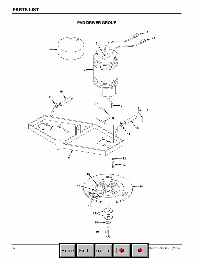
PAD DRIVER GROUP
6
1
4
2
3
7
8
9
11
10
12
13
14
20
21
19
18
17
15
16
11
5

PARTS LIST
27--inch & 33--inch Automatic Floor Scrubber (04--06) 33
PAD DRIVER GROUP
REF PART # DESCRIPTION QTY.
1 100764 COVER, BRUSH MOTOR 2
∇ 2 130491 DMOTOR, W/GEARBOX 24V0.75HP IMP
2
Y 222615 DCARBON BRUSH 4
Y 3 140632 KEY, .25 X .25 X 1.00L 1
4 130191 TERMINAL, FEMALE 2
5 130192 TERMINAL, MALE 2
6 606243 TAPE, DOUBLE STICK 1
7 230691 BRACKET, BRUSH MOTOR MOUNT 1
8 140618 PIN, ROLL 1/4 X 1--1/2 4
9 130041 WIRE TIE 1
10 613439 HOSE, 3/8ID X 14.5 1
∇ ASSEMBLY
Y INCLUDED IN ASSEMBLY
D RECOMMENDED STOCK ITEMS
REF PART # DESCRIPTION QTY.
11 607775 CLAMP, HOSE .63--.66 2
12 140017 WASHER, LOCK, SPLIT, 0.38 SS 8
13 69225 SCREW, HEX, .38--16 X 1.00 SS 8
14 606335 PLATE, DRIVE 2
15 606915 SCREW, #10--16X3/8 HIGH--LOW 4
16 613440 HOSE, 3/8ID X 9” 1
17 230651 CLAMP, BRUSH PLATE 2
18 140417 CLIP, SPRING 2
19 25732 WASHER, 1.25X.359X.093 4
20 140015 WASHER, LOCK, SPLIT, 0.31 SS 2
21 140219 SCREW, HEX, .31--18 X 1.00 SS 2

PARTS LIST
27--inch & 33--inch Automatic Floor Scrubber (05--04)34
BRUSH LIFT GROUP
8
9
1
13
11
12
2
3
56
7
1415
1617
1920
21
1822
23
24
25
26
4
10
2728

PARTS LIST
27--inch & 33--inch Automatic Floor Scrubber (04--06) 35
BRUSH LIFT GROUP
REF PART # DESCRIPTION QTY.
1 604943 PANEL, REAR WELDMENT 1
2 230654 HANDLE, BRUSH PRESSURE 1
3 200816 GRIP, HANDLE .25 X 1 X 2.25 1
4 140144 SLEEVE, .496D, .318B, .33L 1
5 140028 WASHER, FLAT, 0.42B 1.00D .05 SS 1
6 140017 WASHER, LOCK, SPLIT, 0.38 SS 1
7 2949.7 SCREW, HEX, .38--16 X 0.88 1
8 140423 SPRING, BRUSH PRESSURE 2
9 102560 PAD, NON--SLIP 1
10 69225 SCREW, HEX, .38--16 X 1.00 SS 1
11 140017 WASHER, LOCK, SPLIT, 0.38 SS 1
12 140028 WASHER, FLAT, 0.42B 1.00D .05 SS 2
13 230775 LATCH, BRUSH LIFT PEDAL 1
14 140139 SLEEVE, .625D, .500B, .25L 1
REF PART # DESCRIPTION QTY.
15 140045 WASHER, FLAT, 0.51B 1.25D .06 SS 2
16 140024 WASHER, LOCK, 0.50 SS 1
17 140237 SCREW, HEX, .50--13 X 1.00 SS 1
18 230940 PIN, LIFT ARM PIVOT 1
19 140003 WASHER, 1/4X1 FENDER SS 2
20 140016 WASHER, LOCK, 0.25 SS 2
21 15678 SCREW, HEX, M6X1.0X16 SS 2
22 230936 ARM, BRUSH LIFT WELDMENT 1
23 140235 SCREW, HEX, .50--13 X 2.00 SS 1
24 604646 SLEEVE, .625D, .501B, .66L 1
25 02931 NUT, HEX LOCK, .50--13 NL, SS 1
26 102560 PAD, NON--SLIP 1
27 140145 SLEEVE, .625D, .500B, .25L 1
28 140136 BUSHING, .38X.50X.28 1
PARTS LIST
27--inch & 33--inch Automatic Floor Scrubber (05--04)36
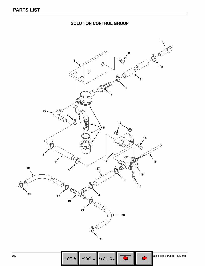
SOLUTION CONTROL GROUP
1
4
5
11
3
13
18 17
12
14
15
16
19
20
10
21
7
9
3
6
8
3
3
3
21
21
21
3
2
14

PARTS LIST
27--inch & 33--inch Automatic Floor Scrubber (04--06) 37
SOLUTION CONTROL GROUP
REF PART # DESCRIPTION QTY.
1 1023581 FITTING, PLSTC, STR, PM08/BM08 1
2 613521 HOSE, 1/2ID X 12” 1
3 607776 CLAMP, HOSE .73--.77 6
4 14884 FITTING, STR, BM08/PM06 1
5 1005302 DFILTER, INLINE, PF06/PF0680--MESH
1
6 605056 BRACKET, MOUNTING, FILTER 2
7 140197 SCREW, TRS, #10--24 X 0.38 PHLSS SEM
4
8 607140 BRACKET, FILTER BOWL 1
9 140197 SCREW, TRS, #10--24 X 0.38 PHLSS SEM
2
10 150425 FITTING, PLSTC, E90, PM06/BM08 1
11 613509 HOSE, 1/2ID X .160FT. 1
D RECOMMENDED STOCK ITEMS
REF PART # DESCRIPTION QTY.
12 41169 NUT, HEX, LOCK, .25--20 NL, SS 4
13 604945 BRACKET, SOLUTION VALVE 1
14 24672 SCREW, HEX, .25--20 X 0.75 SS 4
15 604950 CABLE, SOLUTION CONTROL 1
16 603310 DVALVE, WATER, SOLENOID24VDC 08BM/08BM
1
614265 DKIT, VALVE REBUILD 1
17 613509 HOSE, 1/2ID X .160FT. 1
18 613440 HOSE, 3/8ID X 9” 1
19 1022556 FITTING, TEE, BM06/BM06/BM08 1
20 613439 HOSE, 3/8ID X 14.5” 1
21 607775 CLAMP, HOSE .63--.66 4

PARTS LIST
27--inch & 33--inch Automatic Floor Scrubber (05--04)38
ELECTRICAL GROUP
1
2
3
5
6
7
414
262524
8
9
23
17
1822
21
19
20
18
17
1315
16
12
1110

PARTS LIST
27--inch & 33--inch Automatic Floor Scrubber (04--06) 39
ELECTRICAL GROUP
REF PART # DESCRIPTION QTY.
1 140829 SCREW, PAN, #06--32 X 1, PHL SS 2
2 140019 WASHER, LOCK, EXT, #06 ZN 2
3 605387 DCONNECTOR, RED 50AW/O CONTACTS
1
4 603331 SPACER, CHARGER PLUG 1
5 578403000 SCREW, M3X0.5X20 PANPHL 2
6 601359 PLATE, SWITCH BACKING 1
7 600437 DSWITCH, SNAP ACTION 1
8 602887 BRACKET, CHARGER PLUG 1
9 579211 NUT, M3 HEXLCK 2
10 140539 NUT, #6--32 KEP 2
11 602953 WIRE ASM., RED #6X26” BATTERY 1
12 605905AM DSOLENOID, 24V 1
13 606404 DDIODE ASM, WITH RINGS 1
D RECOMMENDED STOCK ITEMS
REF PART # DESCRIPTION QTY.
14 1026454 SCREW, PAN, M5X0.8X10, PHL, SS 2
15 140000 WASHER, FLAT, 0.28B 0.62D .04 SS 2
16 08712 NUT, HEX, LOCK, M6 X 1.00 SS, NL 2
17 01696 SCREW, HEX, .25--20 X 0.50 SS 2
18 140016 WASHER, LOCK, 0.25 SS 2
19 130390 WIRE ASM., BLACK #6X29”BATTERY
1
20 76062 STANDOFF, TERMINAL 1
21 602951AM DBREAKER, CIRCUIT 35 AMP 2
22 140000 WASHER, FLAT, 0.28B 0.62D .04 SS 1
23 608322 SCREW, TRS, M6X1.0X16 PHL SS 2
24 609969 PLUG, HOUR METER 1
25 130698 BUSHING, SNAP .50ID 1
26 140018 WASHER, LOCK, INT #10 SS 2
PARTS LIST
27--inch & 33--inch Automatic Floor Scrubber (05--04)40
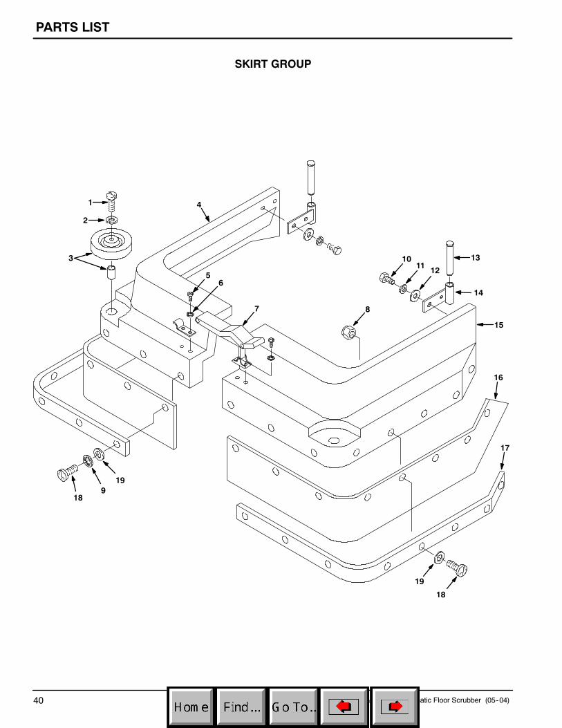
SKIRT GROUP
1
2
3
18
19
19
18
56
7 8
15
121110
4
14
13
16
17
9

PARTS LIST
27--inch & 33--inch Automatic Floor Scrubber (04--06) 41
SKIRT GROUP
REF PART # DESCRIPTION QTY.
1 603154 SCREW, PAN, M8X1.25X40 PHL, SS 2
2 140015 WASHER, LOCK, SPLIT, 0.31 SS 2
3 1014918 WHEEL, 3.0D 1.00W, RUBBER 2
4 607203 SKIRT, 27” RIGHT SIDE, NAVYBLUE
1
607193 SKIRT, 33” RIGHT SIDE, NAVYBLUE
1
5 200070340 SCREW, PAN, M4X0.7X8 PHL, ZN 4
6 140023 WASHER, LOCK, INT #8 SS 4
7 49800 LATCH, HOOD RBR W/ KEEPER 1
8 09739 NUT, M5X0.8 NYLOCK 6--12
9 140018 WASHER, LOCK, INT #10 SS 12-16
10 578237000 SCREW, HEX, M8X1.25X18 SS 4
REF PART # DESCRIPTION QTY.
11 140015 WASHER, LOCK, SPLIT, 0.31 SS 4
12 140027 WASHER, FLAT, 0.35B 0.75D .04 SS 4
13 230943 PIN, SKIRT 2
14 230942 BRACKET, MOUNTING, SKIRT 2
15 607201 SKIRT, 27” LEFT SIDE, NAVY BLUE 1
607191 SKIRT, 33” LEFT SIDE, NAVY BLUE 1
16 240277 SPLASH GUARD, 27” 2
240276 SPLASH GUARD, 33” 2
17 230935.BK STRAP, SPLASH GUARD, 27” 2
230934.BK STRAP, SPLASH GUARD, 33” 2
18 578144000 SCREW, PAN, M5X0.8X16, PHL 22--24
19 140011 WASHER, FLAT, 0.21B 0.45D .03 SS 22--24

PARTS LIST
27--inch & 33--inch Automatic Floor Scrubber (05--04)42
SQUEEGEE CONTROL GROUP
2
76
53
3
574
8
1
1920
21 22
23
24 25
11
18
29
1213
9
10
2728
26
13 16
17
14
30
33
32
31
15

PARTS LIST
27--inch & 33--inch Automatic Floor Scrubber (05--04) 43
SQUEEGEE CONTROL GROUP
REF PART # DESCRIPTION QTY.
1 160613 DHOSE, VAC 1.5 X 30” W/ CUFFS 1
2 604947 HANDLE, SQUEEGEE LIFT 1
3 140134 SLEEVE, .376D, .253B, .28L 2
4 08716 SCREW, HEX, M6X1.0X20 SS 1
5 140000 WASHER, FLAT, 0.28B 0.62D .04 SS 2
6 15678 SCREW, HEX, M6X1.0X16 SS 1
7 140016 WASHER, LOCK, 0.25 SS 2
8 604949 CABLE, SQUEEGEE LIFT 1
9 41169 NUT, HEX, LOCK, .25--20 NL, SS 1
10 604946 BRACKET, SQUEEGEE LIFT 1
11 140209 SCREW, HEX, .25--20X2.50 ZN 1
12 140000 WASHER, FLAT, 0.28B 0.62D .04 SS 1
13 575542000 BEARING, .25IDX.38OD 2
14 41169 NUT, HEX, LOCK, .25--20 NL, SS 1
15 200816 GRIP, HANDLE 1/4 X 1 X 2-1/4 1
16 140000 WASHER, FLAT, 0.28B 0.62D .04 SS 1
17 41169 NUT, HEX, LOCK, .25--20 NL, SS 1
D RECOMMENDED STOCK ITEMS
REF PART # DESCRIPTION QTY.
18 140509 NUT, 1/2--13 HEXJAM 1
19 140237 SCREW, HEX, .50--13 X 1.00 SS 2
20 140024 WASHER, LOCK, 0.50 SS 2
21 3148.816 WASHER, FLT, 0.52B 0.88D .06 STL 4
22 140139 SLEEVE, .625D, .500B, .25L 2
23 140546 NUT, 5/16--18 NYLOCK 2
24 230442 BRACKET, SQUEEGEE MOUNT 1
25 02991 SCREW, HEX, .31--18 X 0.75 SS 2
26 140824 SCREW, 1/4--20X5/8 TRSPHL 1
27 140016 WASHER, LOCK, 0.25 SS 1
28 140003 WASHER, 1/4X1 FENDER SS 1
29 230440.BK BRACKET, SQUEEGEE PIVOT 1
30 1011094 DKNOB 2
31 230443.BK WELDMENT, SQUEEGEE MOUNTPLATE
1
32 140911 SLEEVE, P/M, .622D, .505B, .68L 1
33 140204 SCREW, HEX, .50--13X1.50 SS 1
PARTS LIST
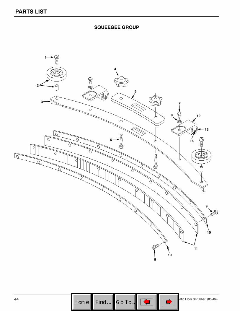
27--inch & 33--inch Automatic Floor Scrubber (05--04)44
SQUEEGEE GROUP
1
2
4
5
3 7
8 12
13
146
910
11
10
9

PARTS LIST
27--inch & 33--inch Automatic Floor Scrubber (05--04) 45
SQUEEGEE GROUP
REF PART # DESCRIPTION QTY.
∇ 603263 ASM, SQUEEGEE, CURVED 27” 1
603264 ASM, SQUEEGEE, CURVED 33” 1
Y 1 140799 SCREW, TRS, .31--18X1.50 PHL, SS 2
Y 2 1014918 WHEEL, 3.0D 1.00W, RUBBER 2
Y 3 602960 SQUEEGEE WELDMENT, 27” 1
603247 SQUEEGEE WELDMENT, 33” 1
Y 4 1011094 DKNOB 2
Y 5 603260 GASKET, SQUEEGEE CURVED 1
Y 6 140221 SCREW, HEX, .31--18X1.25 SS 2
Y 7 140226 SCREW, HEX, .31--18X0.62 SS 2
Y 8 140015 WASHER, LOCK, SPLIT, 0.31 SS 2
Y 9 605975 SCREW, TRS, 10--24X0.50, PHL, SS 24--28
Y 10 602963 PLATE, SQUEEGEE RETAINING27” MODEL
2
603248 PLATE, SQUEEGEE RETAINING33” MODEL
2
∇ ASSEMBLY
Y INCLUDED IN ASSEMBLY
D RECOMMENDED STOCK ITEMS
REF PART # DESCRIPTION QTY.
Y 11 603661 DBLADE, SQUEEGEE 34”STANDARD (FOR 27” MODEL)
2
603662 DBLADE, SQUEEGEE 40”STANDARD (FOR 33” MODEL)
2
OPTIONAL BLADES
606680 DBLADE, SQUEEGEE REAR,GUM RUBBER (FOR 27” MODEL)
2
607467 DBLADE, SQUEEGEE REAR,LINATEX (FOR 27” MODEL)
2
606682 DBLADE, SQUEEGEE REAR,GUM RUBBER (FOR 33” MODEL)
2
607468 DBLADE, SQUEEGEE REAR,LINATEX (FOR 33” MODEL)
2
Y∇ 700844 DASM., SQUEEGEE ROLLER 2
YY12 230474 BRACKET, SQUEEGEE ROLLER 2
YY13 605317 ROLLER 2
YY14 140710 RIVET, AXLE .38D X 1.6 2