27˝ & 30˝ ELECTRIC BUILT-IN MICROWAVE/OVEN COMBINATION · This KitchenAid Job Aid “27˝ & 30˝...
96
TECHNICAL EDUCATION JOB AID 4317410 KAC-46 27˝ & 30˝ ELECTRIC BUILT-IN MICROWAVE/OVEN COMBINATION MODELS: KEMS378S & KEMS308S
Transcript of 27˝ & 30˝ ELECTRIC BUILT-IN MICROWAVE/OVEN COMBINATION · This KitchenAid Job Aid “27˝ & 30˝...

TECHNICAL EDUCATION
JOB AID 4317410
KAC-46
27˝ & 30˝ ELECTRIC BUILT-IN MICROWAVE/OVEN
COMBINATION
MODELS: KEMS378S & KEMS308S

- ii -
WHIRLPOOL CORPORATION assumes no responsibility for any repairs made on our products by anyone other than authorized In-Home Service Professionals.
FORWARDThis KitchenAid Job Aid “27˝ & 30˝ Electric Built-In Microwave/Oven Combination” (Part No. 4317410), provides the In-Home Service Professional with information on the installation, opera-tion, and service of the 27˝ & 30˝ Electric Built-In Microwave/Oven Combination. For specific information on the model being serviced, refer to the “Use and Care Guide,” or “Tech Sheet” provided with the oven.
The Wiring Diagram and Strip Circuits used in this Job Aid are typical and should be used for training purposes only. Always use the Wiring Diagram supplied with the product when servicing the oven.
GOALS AND OBJECTIVESThe goal of this Job Aid is to provide information that will enable the In-Home Service Professional to properly diagnose malfunctions and repair the 27˝ & 30˝ Electric Built-In Microwave/Oven Combination.
The objectives of this Job Aid are to:
• Understand and follow proper safety precautions.• Successfully troubleshoot and diagnose malfunctions.• Successfully perform necessary repairs.• Successfully return the oven to its proper operational status.
Copyright © 2007, Whirlpool Corporation, Benton Harbor, MI 49022

- iii -
TABLE OF CONTENTSPage
GENERAL .............................................................................................................................. 1-1Oven Safety ....................................................................................................................... 1-1Model & Serial Number Designations ................................................................................ 1-3Model & Serial Number Label And Tech Sheet Locations .................................................. 1-4
Specifications ..................................................................................................................... 1-5
INSTALLATION INFORMATION ............................................................................................ 2-1Installation Requirements .................................................................................................. 2-1
Installation Instructions ...................................................................................................... 2-4
PRODUCT OPERATION ....................................................................................................... 3-1
COMPONENT ACCESS ........................................................................................................ 4-1Component Locations ........................................................................................................ 4-1Upper Oven Components ................................................................................................ 4-1Removing The User Interface And The Oven & Microwave Control Board Assemblies ............................................................................................... 4-2Removing The Humidity Sensor And The Cavity Thermostat ............................................ 4-3Removing The Control Power And The Microwave Light Transformers ............................ 4-4Removing The Convection Thermoactuator And The WIDE Interface Board .............................................................................................. 4-5Removing The Monitor Fuse And The Microwave Appliance Manager ............................. 4-6Removing The Microwave Door Interlock Switches And The Cavity Light ......................... 4-7Removing The Magnetron Thermostat And The Magnetron .............................................. 4-9Removing The Main L1 Filter, Main L2 Filter, And Grill Thermostat ..................................4-11Removing The Magnetron Fan Motor & The Inverter ...................................................... 4-13Removing The Convection Thermistor And Grill Element ................................................ 4-16Removing The Lower Oven Appliance Manager .............................................................. 4-18Removing The Line Fuse Holder & Lower Oven Light Transformer ................................ 4-20Removing The AC Terminal Block .................................................................................... 4-21Removing The Convection Thermostat, Ring Element, And Fan Motor .......................... 4-22Removing The Turntable Motor ........................................................................................ 4-24Lower Oven Components .............................................................................................. 4-27Removing The Door Latch Assembly ............................................................................... 4-28Removing The Broil Element And The Oven Temperature Sensor .................................. 4-30Removing The Convection Ring Element And The Convection Fan Motor ..................... 4-32Removing A Halogen Light Assembly And The Meat Probe Jack .................................... 4-34Removing The Blower Assembly, Blower Seed Resistor, And Oven Shutdown Thermal Cutoff .................................................................................... 4-36Removing The Hidden Bake Element .............................................................................. 4-38Removing The Oven Door Glass And Handle .................................................................. 4-40Removing The Oven Door Gasket ................................................................................... 4-42

- iv -
COMPONENT TESTING ........................................................................................................ 5-1UPPER OVEN COMPONENTS ......................................................................................... 5-1 Humidity Sensor ............................................................................................................. 5-1 Cavity Thermostat .......................................................................................................... 5-1 Microwave Light Transformer ......................................................................................... 5-2 Convection Thermoactuator ........................................................................................... 5-2 Monitor Fuse .................................................................................................................. 5-3 Microwave Door Interlock Switches ............................................................................... 5-3 Magnetron Thermostat ................................................................................................... 5-4 Magnetron ...................................................................................................................... 5-4 Main L1 & L2 Filters ....................................................................................................... 5-5 Grill & Convection Thermostats ...................................................................................... 5-5 Magnetron Fan Motor ..................................................................................................... 5-6 Microwave Inverter Board .............................................................................................. 5-6 Grill Element ................................................................................................................... 5-7 Lower Oven Light Transformer ....................................................................................... 5-7 Microwave Convection Ring Element ............................................................................. 5-8 Microwave Convection Fan Motor .................................................................................. 5-8 Turntable Motor .............................................................................................................. 5-9 Measure Oven Input Current .......................................................................................... 5-9LOWER OVEN COMPONENTS ..................................................................................... 5-10 Door Latch Assembly ................................................................................................... 5-10 Broil Element .................................................................................................................5-11 Oven Temperature Sensor ............................................................................................5-11 Convection Ring Element ............................................................................................. 5-12 Convection Fan Motor ................................................................................................. 5-12 Meat Probe Jack .......................................................................................................... 5-13 Blower Motor ................................................................................................................ 5-13 Blower Speed Resistor ................................................................................................. 5-14 Oven Shutdown Thermal Cutoff (TCO) ........................................................................ 5-14
Hidden Bake Element ................................................................................................... 5-15
DIAGNOSTICS & TROUBLESHOOTING ............................................................................. 6-1Diagnostics ........................................................................................................................ 6-1Failure/Error Display Codes ............................................................................................... 6-2Fahrenheit To Celsius Conversion ..................................................................................... 6-7Adjust Oven Temperature Calibration ................................................................................ 6-7 Programming The Cavity Size ........................................................................................... 6-7Keypads ............................................................................................................................. 6-7MW Power Output Test ...................................................................................................... 6-8Relay Logic - Microwave Oven .......................................................................................... 6-8
Relay Logic - Lower Oven .................................................................................................. 6-8
WIRING DIAGRAM & STRIP CIRCUITS .............................................................................. 7-1Wiring Diagram .................................................................................................................. 7-1Strip Circuits ....................................................................................................................... 7-2
Page

1-1
GENERALOVEN SAFETY
Your safety and the safety of others are very important.We have provided many important safety messages in this manual and on the appliance. Always read and obey all safety messages.
This is the safety alert symbol.
This symbol alerts you to potential hazards that can kill or hurt you and others.
All safety messages will follow the safety alert symbol and either the word “DANGER” or “WARNING.” These words mean:
All safety messages will tell you what the potential hazard is, tell you how to reduce the chance of injury, and tell you what can happen if the instructions are not followed.
You can be killed or seriously injured if you don’t immediately follow instructions.
You can be killed or seriously injured if you don’t follow instructions.
DANGERWARNING

1-2
PRECAUTIONS TO BE OBSERVED BEFORE AND DURING SERVICING TO AVOID POSSIBLE EXPOSURE TO
EXCESSIVE MICROWAVE ENERGYa. Do not operate or allow the oven to be operated with the door open.
b. Make the following safety checks on all ovens to be serviced before activating the magnetron or other microwave source, and make repairs as necessary:
1. Interlock Operation2. Proper Door Closing3. Seal and Sealing Surfaces (Arcing, Wear and Other Damage)4. Damage to or Loosening of Hinges and Latches5. Evidence of Dropping or Abuse
c. Before turning on microwave power for any service test or inspection within the microwave generating compartments, check the magnetron, waveguide or transmission line and cavity for proper alignment, integrity and connections.
d. Any defective or misadjusted components in the interlock, monitor, door seal, and microwave generation, and transmission systems shall be repaired, replaced, or adjusted by procedures described in service manual before the oven is released to the owner.
e. A microwave leakage check to verify compliance with the Federal performance standard should be performed on each oven prior to release to the owner.
f. Do not attempt to operate the oven if the door glass is broken.

1-3
MODEL NUMBER K EM S 30 8 S SS 0
PRODUCT GROUP K = KITCHENAID PRODUCT IDENTIFICATION EB = ELECTRIC BUILT-IN OVEN EH = ELECTRIC BUILT-IN HI SPEED COMBO EM = ELECTRIC BUILT-IN MICRO COMBO EW = ELECTRIC WARMING OVEN/DRAWER GB = GAS BUILT-IN OVEN GM = GAS BUILT-IN MICRO COMBO OVEN
MERCHANDISING SCHEME A = ARCHITECT C = FLUSH LOOK D = DRAWER I = IMPERIAL N = INTERNATIONAL COLLECTION EUROPEAN S = SUPERBA V = VBL PRO LINE SERIES
CAPACITY / SIZE / SERIES / CONFIGURATION 1ST POSITION 2ND POSITION 1 = SINGLE OVEN 4 = 24˝ WIDE 2 = DOUBLE OVEN 6 = 36˝ WIDE 3 = COMBO OVEN 7 = 27˝ WIDE 5 = MINI OVEN 0 = 30˝ WIDE 6 = COMBO W/MINI OVEN
FEATURE CODE 0 = STANDARD FEATURES 1 = STANDARD FEATURES / ELEC COOK 2 = INDOOR / OUTDOOR FEATURES 5 = DELUXE FEATURES 6 = DELUXE FEATURES / ELEC. CLOCK 7 = DELUXE FEATURES / TH ERMAL CONVECTION 8 = DOUBLE THERMAL CONVECTION 9 = MULTI-MODE
YEAR OF INTRODUCTION S = 2006
COLOR CODE BL = BLACK SS = STAINLESS STEEL BT = BISCUIT WH = WHITE
ENGINEERING CHANGE (0, 1, 2, ETC.)
SERIAL NUMBER X T 41 01002DIVISION RESPONSIBILITY X = OXFORDYEAR OF PRODUCTION T = 2006WEEK OF PRODUCTION 41 = 41ST WEEKPRODUCT SEQUENCE NUMBER
MODEL & SERIAL NUMBER DESIGNATIONS
1-4
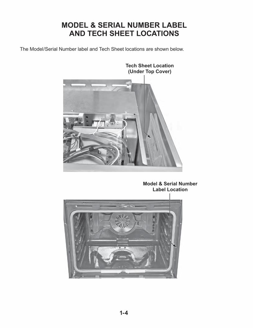
MODEL & SERIAL NUMBER LABELAND TECH SHEET LOCATIONS
The Model/Serial Number label and Tech Sheet locations are shown below.
Model & Serial Number Label Location
Tech Sheet Location(Under Top Cover)

1-5
SPECIFICATIONS
Model Number KEMS378SBL, BT, SS, WH KEMS308SBL, BT,SS,WH
Model Description MW/BI Combo MW/BI Combo
Size - Configuration 27˝ 30˝Feature Level/Series Superba Superba
Predecessor Model (Model This Model Replaces)
KEMC377KBL/KEMC378KBL/KEHC379JBL
KEMC307KBL/KEMC308KBL/KEHC309JBL
Dimensions
Exterior Dimensions
Overall Height 42˝ 42˝
Overall Width 26-3/4˝ 29-3/4˝
Overall Depth (Includes Hdw/Handle) 26˝ 26˝
Depth w/Door Open 90° 43-3/4˝ 43-3/4˝
Door Swing 15-3/8˝ 15-3/8˝
Cutout Dimensions
Cutout Height (Measure or Min/Max) 41-1/4˝ 41-1/4˝
Cutout Width (Measure or Min/Max) 25-1/2˝ 28-1/2˝
Cutout Depth (Measure or Min/Max) 23-1/4˝ 23-1/4˝
Other Dimensions
Conduit Size (Length/Diameter) 57˝ / 1/2˝ 57˝ / 1/2˝
Ratings
Electric Voltage/Phase/Frequency (Hz) 208V / 240V / 2-3 / 60 208V / 240V / 2-3 / 60
Total Connected Load in kW
240 Volts 11.35 11.21
208 Volts 9.24 9.10
240/120V AC 11.42 11.42
Circuit Amps 40 40
Upper/Microwave Oven
Distribution Type Lateral Feed w/o Stirrer Lateral Feed w/o Stirrer
Magnetron Type Inverter Inverter
Temperature Sensor Yes Yes
Microwave Timer Yes Yes
Timer Limits (Min:Sec) 99:99 99:99
Timer Control Type Electronic Electronic
Timer Scale Linear (Digital) Linear (Digital)
MW Cavity Material Stainless Stainless
1-6
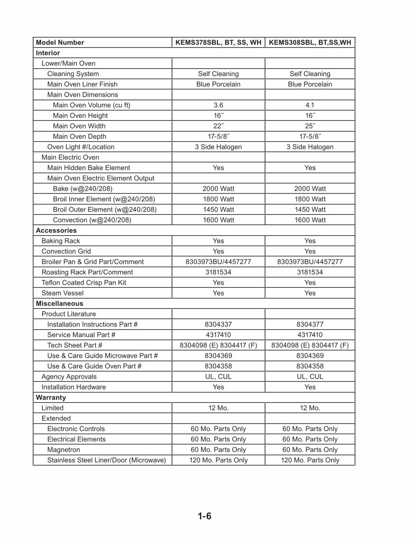
Model Number KEMS378SBL, BT, SS, WH KEMS308SBL, BT,SS,WH
Interior
Lower/Main Oven
Cleaning System Self Cleaning Self Cleaning
Main Oven Liner Finish Blue Porcelain Blue Porcelain
Main Oven Dimensions
Main Oven Volume (cu ft) 3.6 4.1
Main Oven Height 16˝ 16˝
Main Oven Width 22˝ 25˝
Main Oven Depth 17-5/8˝ 17-5/8˝
Oven Light #/Location 3 Side Halogen 3 Side Halogen
Main Electric Oven
Main Hidden Bake Element Yes Yes
Main Oven Electric Element Output
Bake (w@240/208) 2000 Watt 2000 Watt
Broil Inner Element (w@240/208) 1800 Watt 1800 Watt
Broil Outer Element (w@240/208) 1450 Watt 1450 Watt
Convection (w@240/208) 1600 Watt 1600 Watt
Accessories
Baking Rack Yes Yes
Convection Grid Yes Yes
Broiler Pan & Grid Part/Comment 8303973BU/4457277 8303973BU/4457277
Roasting Rack Part/Comment 3181534 3181534
Teflon Coated Crisp Pan Kit Yes Yes
Steam Vessel Yes Yes
Miscellaneous
Product Literature
Installation Instructions Part # 8304337 8304377
Service Manual Part # 4317410 4317410
Tech Sheet Part # 8304098 (E) 8304417 (F) 8304098 (E) 8304417 (F)
Use & Care Guide Microwave Part # 8304369 8304369
Use & Care Guide Oven Part # 8304358 8304358
Agency Approvals UL, CUL UL, CUL
Installation Hardware Yes Yes
Warranty
Limited 12 Mo. 12 Mo.
Extended
Electronic Controls 60 Mo. Parts Only 60 Mo. Parts Only
Electrical Elements 60 Mo. Parts Only 60 Mo. Parts Only
Magnetron 60 Mo. Parts Only 60 Mo. Parts Only
Stainless Steel Liner/Door (Microwave) 120 Mo. Parts Only 120 Mo. Parts Only

2-1
INSTALLATION INFORMATIONINSTALLATION REQUIREMENTS
TOOLS AND PARTSGather the required tools and parts before start-ing installation. Read and follow the instructions provided with any tools listed here.
Tools needed
Phillips screwdriverMeasuring tapeHand or electric drill (for wall cabinet instal-lations)1˝ (25 mm) drill bit (for wall cabinet instal-lations)Level
Parts needed
UL listed or CSA approved conduit connec-torUL listed wire connectors
Parts supplied
# 8-14 x 1˝ screws - single oven (2), double oven (4)Bottom vent (supplied on some models)Two # 8-18 x 3/8˝ screws - bottom vent (sup-plied on some models)
Check local codes. Check existing electrical supply. See “Electrical Requirements,” page 2-2. It is recommended that all electrical con-nections be made by a licensed, qualified electrical installer.
LOCATION REQUIREMENTSMake sure you have everything needed for correct installation. It is the responsibility of the installer to comply with the installation clear-ances specified in these instructions.
IMPORTANT: Observe all governing codes and ordinances.
Cabinet opening dimensions that are shown must be used. Given dimensions provide minimum clearance with oven.
•••
•
•
•
•
•
••
•
Recessed installation area must provide complete enclosure around the recessed portion of the oven.
Grounded electrical supply is required. See “Electrical Requirements,” page 2-2.
Electrical supply junction box should be located 3˝ (7.6 cm) maximum below the support surface when the oven is installed in a wall cabinet. A 1˝ (2.5 cm) minimum di-ameter hole should have been drilled in the right rear or left rear corner of the support surface to pass the appliance cable through to the junction box.
Oven support surface must be solid, level and flush with bottom of cabinet cutout. Floor must be able to support a total weight (microwave and built-in oven) of 238 lbs (108 kg).
Product Dimensions
27˝ (68.6 cm) and 30˝ (76.2 cm) Ovens
•
•
•
•
27˝ (68.6 cm) modelsA. 25-5/16B. 42-5/16
˝ (64.3 cm) recessed width˝ (107.5 cm) overall height
C. 26-3/4˝ (67.9 cm) overall widthD. 23˝ (58.4 cm) max. recessed
depthE. 40-3/4˝ (103.5 cm) recessed
height
30˝ (76.2 cm) modelsA. 28-5/16B. 42-5/16
˝ (71.9 cm) recessed width˝ (107.5 cm) overall height
C. 29-3/4˝ (75.6 cm) overall widthD. 23˝ (58.4 cm) max. recessed
depthE. 40-3/4˝ (103.5 cm) recessed
height
A
B
D
E
C

2-2
Cabinet Dimensions
27˝ (68.6 cm) and 30˝ (76.2 cm) Ovens
27˝ (68.6 cm) models
A. 27˝ (68.6 cm) min. cabinet width
B. 1˝ (2.5 cm) top of cutout to bottom of upper cabinet door
C. 19-1/4˝ (48.9 cm) bottom of cutout to floor
D. 25-1/2˝ (64.8 cm) cutout widthE. 1-1/2˝ (3.8 cm) min. bottom of
cutout to top of cabinet doorF. 41-1/4˝ (104.8 cm) cutout height
30˝ (76.2 cm) models
A. ˝ (76.2 cm) min. cabinet width
B. 1˝ (2.5 cm) top of cutout to bottom of upper cabinet door
C. 19-1/4
30
˝ (48.9 cm) bottom of cutout to floor
D. 28-1/2˝ (72.4 cm) cutout widthE. 1-1/2˝ (3.8 cm) min. bottom of
cutout to top of cabinet doorF. 41-1/4˝ (104.8 cm) cutout height
A
B
C
D
E
F
Cabinet Side View
A. Model/serial number plate
A
A. 23-1/4˝ (59.1 cm) min. cutout depthB. 23˝ (58.4 cm) recessed oven depthC. Oven frontD. Recessed ovenE. Cabinet
A
B
CD
E
ELECTRICAL REQUIREMENTSIf codes permit and a separate ground wire is used, it is recommended that a qualified elec-trical installer determine that the ground path and wire gauge are in accordance with local codes.
It is not recommended to ground to a gas pipe.
Check with a qualified electrical installer if you are not sure the oven is properly grounded.
It is not recommended to have a fuse in the neutral or ground circuit.
This oven must be connected to a grounded metal, permanent wiring system.
Be sure that the electrical connection and wire size are adequate and in conformance with the National Electrical Code, ANSI/NFPA 70-latest edition or CSA Standards C22.1-94, Canadian Electrical Code, Part 1 and C22.2 No. O-M91-latest edition, and all local codes and ordinances.
A copy of the above code standards can be obtained from:
National Fire Protection AssociationOne Batterymarch Park
Quincy, MA 02269
CSA International8501 East Pleasant Valley Road
Cleveland, OH 44131-5575
Electrical Connection
To properly install your oven, you must deter-mine the type of electrical connection you will be using and follow the instructions provided for it here.
Oven must be connected to the proper elec-trical voltage and frequency as specified on the model/serial number rating plate. The model/serial number rating plate is located at the bottom of the right-hand mounting rail. See the following illustration.
•

2-3
Models rated from 7.3 to 9.6 kW at 240 volts (5.5 to 7.2 kW at 208 volts) require a separate 40-amp circuit. Models rated at 7.2 kW and below at 240 volts (5.4 kW and below at 208 volts) require a separate 30-amp circuit.
A time-delay fuse or circuit breaker is recom-mended.
Connect directly to the fused disconnect (or circuit breaker box) through flexible, armored or nonmetallic sheathed, copper cable (with grounding wire). See “Make Electrical Con-nection,” page 2-5.
Flexible cable from the oven should be con-nected directly to the junction box.
Fuse both sides of the line.
•
•
•
•
•
Do not cut the conduit. The length of conduit provided is for serviceability of the oven.
A UL listed or CSA approved conduit con-nector must be provided.
If the house has aluminum wiring follow the procedure below:
1. Connect a section of solid copper wire to the pigtail leads.
2. Connect the aluminum wiring to the added section of copper wire using special con-nectors and/or tools designed and UL listed for joining copper to aluminum.
Follow the electrical connector manufacturer’s recommended procedure. Aluminum/copper connection must conform with local codes and industry accepted wiring practices.
•
•
•

2-4
INSTALLATION INSTRUCTIONSPREPARE BUILT-IN MICROWAVE/OVEN COMBINATION1. Decide on the final location for the oven.
Locate existing wiring to avoid drilling into or severing wiring during installation.
Excessive Weight Hazard
Use two or more people to move and install oven.
Failure to do so can result in back or other injury.
WARNING
2. To avoid floor damage, set the oven onto cardboard prior to installation. Do not use handle or any portion of the front frame for lifting.
3. Remove the shipping materials and tape from the oven.
4. Remove the hardware package from inside the bag containing literature.
5. Remove and set aside racks and other parts from inside the oven.
6. Move oven and cardboard close to the oven’s final location.
3. Grasp the edges of the oven door with both hands and close the oven door until it will no longer close. Lift and pull oven door toward you and remove. Set the oven door aside on a covered work surface.
A. Oven door latch in locked position
B. Oven door latch in unlocked position
A B
REMOVE OVEN DOORIMPORTANT: Use both hands to remove oven door.
1. Open the oven door.
2. Locate the oven door latches in both corners of the oven door, and rotate the latches forward to the unlocked position.

2-5
MAKE ELECTRICAL CONNECTION
Electrical Shock Hazard
Disconnect power before servicing.
Use 8 gauge solid copper wire.
Electrically ground oven.
Failure to follow these instructions can result in death, fire, or electrical shock.
WARNING
This oven is manufactured with a neutral (white) power supply wire and a cabinet-connected green (or bare) ground wire twisted together.
1. Disconnect power.
2. Feed the flexible cable conduit from the oven through the opening in the cabinet.
3. Remove junction box cover if it is present.
4. Install a UL listed or CSA approved conduit connector to the junction box.
A. UL listed or CSA approved conduit connector
A
Electrical Connection Options Chart
A. Cable from home power supplyB. Black wiresC. Red wiresD. 4-wire flexible cable from ovenE. Junction box
F. White wiresG. UL listed wire connectorsH. Green (or bare) ground wiresI. UL listed or CSA approved
conduit connector
AB
C
D
EF
G
H
I
½"
If your home has: Go to section:
4-wire 4-wire Cable from Home Power Supply
3-wire 3-wire Cable from Home Power Supply
(1.3 cm)
½"(1.3 cm)
4-Wire Cable from Home Power Supply
IMPORTANT: Use the 4-wire cable from home power supply in the U.S. where local codes do not allow grounding through neutral, New Branch circuit installations (1996 NEC), mobile homes and recreational vehicles, new construc-tion and in Canada.
5. Route the flexible cable conduit from the oven to the junction box through a UL listed or CSA approved conduit connector.
6. Tighten screws on conduit connector.
7. See “Electrical Connection Options Chart” to complete installation for your type of electrical connection.
1. Connect the 2 black wires (B) together using a UL listed wire connector.
2. Connect the 2 red wires (C) together using a UL listed wire connector.
3. Untwist white wire from green (or bare) ground wire coming from the oven.
4. Connect the 2 white wires (F) together using a UL listed wire connector.
5. Connect the green (or bare) ground wire (H) from the oven cable to the green (or bare) ground wire (in the junction box) us-ing a UL listed wire connector.
6. Install junction box cover.

2-6
INSTALL OVEN
Excessive Weight Hazard
Use two or more people to move and install oven.
Failure to do so can result in back or other injury.
WARNING
1. Using 2 or more people, lift oven partially into cabinet cutout using the oven opening as an area to grip.
NOTE: Push against seal area of oven front frame when pushing oven into cabinet. Do not push against outside edges.
2. Push against seal area of front frame to push oven into cabinet.
3. Push oven completely into cabinet and center oven into cabinet cutout.
3-Wire Cable from Home Power Supply - U.S. Only
IMPORTANT: Use the 3-wire cable from home power supply where local codes permit a 3-wire connection.
A. Cable from home power supplyB. Junction boxC. Black wiresD. White wiresE. Green (or bare) ground wire
(from oven)
F. 4-wire flexible cable from oven
G. Red wiresH. UL listed wire connectorsI. UL listed or CSA approved
conduit connector
BC
D
E
F
H
G
A
I
1. Connect the 2 black wires (C) together using a UL listed wire connector.
2. Connect the 2 white wires (D) and the green (or bare) ground wire (of the oven cable) using a UL listed wire connector.
3. Connect the 2 red wires (G) together using a UL listed wire connector.
4. Install junction box cover.

2-7
4. Securely fasten oven to cabinet using the #8-14 x 1˝ screws (2 for single oven, 4 for double oven) provided. Insert the screws through holes in mounting rails. Do not overtighten screws.
A. Mounting railB. Insert #8-14 x 1" screw.
A
B
5. On some models, the oven vent is taped to the side of the oven.
With one #8-14 x 3/8˝ screw for each side of the vent, fasten vent securely to the oven.
A. #8-14 x 3/8 screwB. Oven vent
AB
6. Replace oven racks.
7. Replace oven door by inserting ends of hinges into hinge slots in the oven frame.
8. Push hinges in as far as they will go and open the oven door. You should feel the oven door drop into place.
9. Rotate both hinge latches back to the locked position.
10. Check that the door is free to open and close. If it is not, repeat the removal and installation procedures. See “Remove Oven Door,” page 2-4.
11. Reconnect power.
12. Display panel will light briefly, and “PF” should appear in the display.
13. If display panel does not light, please refer-ence the “Assistance or Service” section of the Use and Care Guide or contact the dealer from whom you purchased your oven.
COMPLETE INSTALLATION1. Check that all parts are now installed. If
there is an extra part, go back through the steps to see which step was skipped.
2. Check that you have all of your tools.
3. Dispose of/recycle all packaging materials.
4. For oven use and cleaning, read the Use and Care Guide.
Check Operation of Lower Oven
1. Turn power on.
2. When “CLOCK ENTER TIME” appears in the lower oven display touch START.
3. Touch BROIL.
4. Touch START.
If oven does not operate, check the following:
Household fuse is intact and tight; or circuit breaker has not tripped.Electrical supply is connected.See “Troubleshooting” section in the Use and Care Guide.
5. When oven has been on for 5 minutes, feel for heat. If you do not feel heat or if an error code (“F” followed by a number plus “E” followed by a number) appears in the display, turn off the oven and contact a qualified technician.
6. Touch LOWER OVEN OFF.
•
••

2-8
Check Operation of Microwave Oven
1. Fill a microwave-safe container with 1 cup (250 mL) of water and place container inside microwave oven. Close door firmly.
2. Set microwave oven cook time to “2:00” minutes.
3. Touch START. The interior microwave oven light should be on, and the remaining cook-ing time should be displayed in the upper oven display.
If microwave does not operate, check the following:
Household fuse is intact and tight; or circuit breaker has not tripped.Electrical supply is connected.See “Troubleshooting” section in the Use and Care Guide.When display reads “1:00” minute, open microwave oven door. The microwave should stop cooking. Close door firmly. The interior microwave oven light should turn off.
•
••
•
4. Touch START to resume preset cycle. The microwave oven should begin cooking, and the microwave oven interior light should be on.
Let microwave oven complete cooking time. A tone will sound 3 times at the end of the cooking time, and the microwave oven will shut off.
5. Open microwave oven door and slowly re-move container. Water in container should be hot.
If you need Assistance or Service:
Please reference the “Assistance or Service” section of the Use and Care Guide or contact the dealer from whom you purchased your built-in and microwave ovens.

3-1
PRODUCT OPERATION
% OZFC LBSPOWER
TIMER MAXIMUM TIME REMAINING
% OZFC LBSPOWER
TIMER MAXIMUM TIME REMAINING
CONTROL LOCKThe Control Lock shuts down the control panel keys to avoid unintended use of the oven. The Control Lock will remain set after a power failure, if set before the power failure occurs.
When the control is locked, only the TIMER SET/START, TIMER OFF and OVEN LIGHT keys will function.
The Control Lock is preset unlocked, but can be locked.
To Lock Control: Touch and hold START for approximately 5 seconds, until “control locked” appears on the lower text line and a lock icon appears in the display.
To Unlock Control: Repeat to unlock and re-move “control locked” and lock icon from the display.
DONENESSDoneness may be adjusted to more done, less done, or back to normal doneness (default) for all automatic cooking functions except Popcorn, EasyConvect™, Custom Reheat (manual), Cus-tom Defrost (manual) and Steam (manual).
To Change Doneness Setting:
During programming, before touching START, touch POWER once for MORE, twice for LESS or 3 times for NORMAL.
ELECTRONIC OVEN CONTROL

3-2
SABBATH MODEThe Sabbath Mode sets the oven to remain on in a bake setting until turned off. A timed Sab-bath Mode can also be set to keep the oven on for only part of the Sabbath.
When the Sabbath Mode is set, only the number and start keys will function, no tones will sound, and the displays will not show messages or tem-perature changes. The heat sources icons will appear lit on the lower oven display throughout the Sabbath Mode.
When the Sabbath Mode is set the lower oven is disabled and no function is allowed. When the oven door is opened or closed, the oven light will not turn on or off and the heating elements will not turn on or off immediately.
If a power failure occurs when the Sabbath Mode is set, the oven will remain in Sabbath Mode but will no longer be actively cooking. The “ON” indicator will no longer be lit. Touch OFF to return to normal operating mode (non-Sabbath Mode, not cooking).
To Activate:
Before the Sabbath Mode can be regularly set, the oven must first be enabled with a one time only setup.
1. Open the oven door.
2. Touch OFF.
3. Touch the number keys 7, 8, 9, 6, in this order.
4. Touch START to activate. “SABBATH ENABLED” will appear on the display.
5. Touch OFF to clear the display.
6. Close oven door.
To Deactivate:
The oven can be disabled of the ability to set the Sabbath Mode by repeating the previous steps. See the “To Activate” section. When disabled “SABBATH DISABLED” will appear on the display. The Sabbath Mode cannot be regularly set until re-enabled.
During convection broiling, the broil elements will cycle on and off in intervals to maintain oven temperature, while the fan constantly circulates the hot air.
The temperature is preset at 450°F (232°C), but can be changed to a different temperature. Cooking times will vary depending on the rack position and temperature and may need to be adjusted.
If the oven door is opened during convection broiling, fan turns off immediately when door is opened and turns on again immediately when door is closed. Broil elements will turn off approximately 30 seconds after the door is opened. They will turn on again approximately 30 seconds after the door is closed.
CONVECTION BROIL
A. Broil heatB. Convection fan
B
A

3-3
The temperature probe accurately measures the internal temperature of meat, poultry and casseroles with liquid and should be used in determining the doneness of meat and poultry. It should not be used during full and center broiling, convection broiling, dehydrating or proofing bread.
Always unplug and remove the temperature probe from the oven when removing food.
WARNINGTEMPERATURE PROBE
Burn Hazard
Use an oven mitt to remove temperature probe.
Do not touch broil element.
Failure to follow these instructions can result in burns.
DEHYDRATING (on convection models, closed door)Dehydration is a method used to preserve food. Various factors, such as the quality of the fresh food, pretreatment techniques, the size and thickness of the food, and the climate may af-fect the finished product.
During dehydration, heat is used to force out moisture and air circulation is used to carry the moisture away.
Refer to a reliable book or source for complete information about dehydrating and preserving foods.
NOTE: The oven will automatically turn off after 12 hours. However, some foods may take more than 12 hours to dehydrate. If this is the case, the oven will need to be restarted.

3-4
— NOTES —
4-1
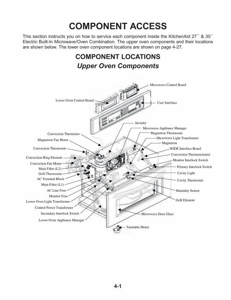
COMPONENT LOCATIONSUpper Oven Components
This section instructs you on how to service each component inside the KitchenAid 27˝ & 30˝ Electric Built-In Microwave/Oven Combination. The upper oven components and their locations are shown below. The lower oven component locations are shown on page 4-27.
COMPONENT ACCESS
Convection Ring Element
Microwave Control Board
Lower Oven Control Board
Convection Fan Motor
Turntable Motor
Grill Element
Cavity Light
AC Line Fuse
Main Filter (L2)
Secondary Interlock Switch
Convection Thermoactuator
MagnetronMagnetron Fan Motor
Monitor Interlock Switch
Primary Interlock Switch
Microwave Light Transformer
Control Power Transformer
Cavity Thermostat
Humidity SensorMonitor Fuse
Lower Oven Light Transformer
Lower Oven Appliance Manager
Main Filter (L1)
Microwave Door Glass
WIDE Interface Board
Magnetron ThermostatMicrowave Appliance Manager
Convection Thermistor
Inverter
User Interface
Convection Thermostat
Grill ThermostatAC Terminal Block

4-2
REMOVING THE USER INTERFACE AND THE OVEN & MICROWAVE CONTROL BOARD ASSEMBLIES
WARNING
1. Unplug oven or disconnect power.
2. Open the microwave oven door and remove the two flat-head screws from the bottom of the control panel frame.
3. Remove the control panel frame and close the microwave oven door.
Electrical Shock Hazard
Disconnect power before servicing.
Replace all parts and panels before operating.
Failure to do so can result in death or electrical shock.
Control Panel Frame Screws
4. To remove the user interface (UI):
a) Remove the screw from the bracket on the right side of the user interface and remove the bracket.
b) Slide the user interface to the right, unhook it from the left bracket, and rotate the top forward and down.
c) Disconnect the two ribbon cable con-nectors from the user interface and remove the interface.
UI Bracket Screw
Slide & Unhook UI
User Interface
User Interface Ribbon Cables
5. To remove the oven and microwave (MW) control board assemblies:
a) Remove the user interface (see step 4).
b) Remove the indicated screws from the oven or MW control board brackets.
MW Control Board Screws
c) Rotate the top of the MW or oven con-trol board assembly forward and down, and disconnect the connectors from the board as follows:
P1 (8-pin) P2 (5-pin) P40 (ribbon cable)
MW Control Board
P40 P2 P1
Oven Control Board Screws
Oven Control Board
P40 P2 P1

4-3
REMOVING THE HUMIDITY SENSOR AND THE CAVITY THERMOSTAT
WARNING
1. Unplug oven or disconnect power.
2. Open the microwave oven door, remove the two flat-head screws from the bottom of the control panel frame, and remove the frame.
Electrical Shock Hazard
Disconnect power before servicing.
Replace all parts and panels before operating.
Failure to do so can result in death or electrical shock.
5. To remove the humidity sensor:
a) Remove the two screws from the hu-midity sensor.
6. To remove the cavity thermostat:
a) Remove the two screws from the cavity thermostat.
b) Disconnect the two white wire connec-tors from the cavity thermostat terminals and remove the thermostat.
Cavity Thermostat Screws
Humidity Sensor Screws
Control Panel Frame Screws
3. Remove the four screws from the front subpanel and remove the subpanel as-sembly.
4. Disconnect the P1 and P2 connectors from the microwave and lower oven control board connectors and set the panel assembly aside.
Front Subpanel Screws
P2 P1 P2 P1
Lower Oven Board MW Oven Board
Humidity Sensor Cavity Thermostat
MW Relay Board
b) Disconnect the sensor from microwave relay board connector HUM.
c) Cut the humidity sensor cable from the harness and remove the sensor.
Humidity Sensor Connector (HUM)
Wire Connectors

4-4
REMOVING THE CONTROL POWER AND THE MICROWAVE LIGHT TRANSFORMERS
WARNING
Electrical Shock Hazard
Disconnect power before servicing.
Replace all parts and panels before operating.
Failure to do so can result in death or electrical shock.
MW Light Transformer
5. To remove the control power trans-former:
a) Disconnect the 2-wire transformer connec-tor from the left side panel connector.
b) Remove the two screws from the trans-former and remove the transformer.
2-Wire Connector
Screws
6. To remove the microwave light trans-former:
a) Disconnect the two pink wire connectors from the LOAD terminals, and the two brown wire connectors from the LINE terminals.
b) Remove the two screws from the trans-former and remove the transformer.
BR Wires
PK Wires
MW Light Transformer
Screw
Screw
1. Unplug oven or disconnect power.
2. Open the microwave oven door, remove the two flat-head screws from the bottom of the control panel frame, and remove the frame.
Control Panel Frame Screws
3. Remove the four screws from the front subpanel and remove the subpanel as-sembly.
4. Disconnect the P1 and P2 connectors from the microwave and lower oven control board connectors and set the panel assembly aside.
Front Subpanel Screws
P2 P1 P2 P1
Lower Oven Board MW Oven Board
Control Power Transformer
Control Power Transformer Screws
2-Wire Connector

4-5
REMOVING THE CONVECTION THERMOACTUATOR AND THE WIDE INTERFACE BOARD
WARNING
Electrical Shock Hazard
Disconnect power before servicing.
Replace all parts and panels before operating.
Failure to do so can result in death or electrical shock.
5. To remove the convection thermoactuator:
a) Disconnect the two wire connectors from the terminals.
b) Remove the two screws and remove the thermoactuator.
6. To remove the WIDE interface board:
a) Disconnect the two wire connectors at P1 and U3.
b) Push and unlock the tab and remove the WIDE interface board from its bracket.
P1
U3
Tab
WIDE Interface Board
1. Unplug oven or disconnect power.
2. Open the microwave oven door, remove the two flat-head screws from the bottom of the control panel frame, and remove the frame.
Control Panel Frame Screws
3. Remove the four screws from the front subpanel and remove the subpanel as-sembly.
4. Disconnect the P1 and P2 connectors from the microwave and lower oven control board connectors and set the panel assembly aside.
Front Subpanel Screws
P2 P1 P2 P1
Lower Oven Board MW Oven Board
Convection Thermoactuator
WIDE Interface Board
Wire Connectors
Thermoactuator Screws

4-6
REMOVING THE MONITOR FUSE AND THE MICROWAVE APPLIANCE MANAGER
WARNING
Electrical Shock Hazard
Disconnect power before servicing.
Replace all parts and panels before operating.
Failure to do so can result in death or electrical shock.
5. To remove the monitor fuse holder:
a) Remove the fuse from the fuse holder.b) Disconnect the two wire connectors
from the fuse holder terminals.c) Remove the screw from the fuse holder
and remove the fuse holder.
6. To remove the microwave appliance manager:
a) Remove the two screws from the left side of the board and remove the board from its holder.
b) Disconnect the wire connectors from the board (see below for the wiring).
Fuse Holder Screw
BRBR
Microwave Appliance Manager Screws
RL1BU
RL2RD
RL3BR
WH(SM)
BK WH(LG)
P3BU-YL
2 BK-2 BR & 4 BK
P106-Pin
HUM3-Pin
P62-Pin
P83-Pin
1. Unplug oven or disconnect power.
2. Open the microwave oven door, remove the two flat-head screws from the bottom of the control panel frame, and remove the frame.
Control Panel Frame Screws
3. Remove the four screws from the front subpanel and remove the subpanel as-sembly.
4. Disconnect the P1 and P2 connectors from the microwave and lower oven control board connectors and set the panel assembly aside.
Front Subpanel Screws
P2 P1 P2 P1
Lower Oven Board MW Oven Board
Monitor Fuse
P1=BU-BR
Monitor Fuse
Microwave Appliance Manager

4-7
REMOVING THE MICROWAVE DOOR INTERLOCK SWITCHES AND THE CAVITY LIGHT
WARNING
Electrical Shock Hazard
Disconnect power before servicing.
Replace all parts and panels before operating.
Failure to do so can result in death or electrical shock.
1. Unplug oven or disconnect power.
2. Open the microwave oven door, remove the two flat-head screws from the bottom of the control panel frame, and remove the frame.
Control Panel Frame Screws
3. Remove the four screws from the front subpanel and remove the subpanel as-sembly.
4. Disconnect the P1 and P2 connectors from the microwave and lower oven control board connectors and set the panel assembly aside.
Front Subpanel Screws
P2 P1 P2 P1
Lower Oven Board MW Oven Board
Sec. Interlock Sw. Primary & Monitor Interlock Switches
5. To remove the secondary interlock switch:
a) Remove the two mounting bracket screws from the front of the switch holder on the left front side of the MW oven, and remove the holder.
b) Disconnect the blue (COM) and white (N.O.) wires from the switch termi-nals.
c) Raise the locking tabs and pull the switch off the pins and out of the switch holder.
Cavity Light
Sec. Interlock Sw. Screws
Secondary Interlock Sw.
BU (COM)
WH (N.O.)
Continued on the next page.

4-8
6. To remove the primary or monitor in-terlock switch:
a) Place the blade of a flat-blade screw-driver between the switch body and the holder. Twist the blade until the switch is free of the tabs, and remove the switch from the holder.
b) Primary (front): Disconnect the brown (COM), white (N.O.), and blue (N.C.) wires from the switch terminals.
c) Monitor (rear): Disconnect the red (COM) and blue (N.C.) wires from the switch terminals.
Primary Interlock Switch
Monitor Interlock Switch
Twist Screwdriver
Primary Interlock Switch BU (N.C.)
WH (N.O.)
BR (COM)
RD (COM)
BU (N.C.)
Monitor Interlock Switch
7. To remove the cavity light:
a) Disconnect the two pink cavity light LOAD wires from the microwave light transformer terminals.
b) Squeeze the light wire clips, remove the ends from the slot in the chassis, and lift the light and remove it from the chassis.
Pink LOAD Wires
Microwave Light Transformer
Cavity Light Chassis Slot
Wire Clip

4-9
REMOVING THE MAGNETRON THERMOSTAT AND THE MAGNETRON
WARNING
Electrical Shock Hazard
Disconnect power before servicing.
Replace all parts and panels before operating.
Failure to do so can result in death or electrical shock.
4. To remove the magnetron thermostat:
a) Disconnect the two wire connectors from the thermostat terminals.
b ) Remove the two screws from the ther-mostat and remove the thermostat.
5. To remove the magnetron:
a) Remove the magnetron thermostat (see step 4).
b) Remove the eight screws from the inner cover and remove the cover.
Inner Cover Screws (3 of 8)
c) Remove the right screw from the mi-crowave appliance manager board bracket.
Top Cover
Screws (2 of 4)
1. Unplug oven or disconnect power.
2. Remove the oven from its mounting location (see “Installation Information” in Section 2) and pull it forward so that you can access the top cover.
3. Remove the four screws from the top cover and remove the cover.
Magnetron Thermostat Screw (1 of 2)
Wire Connectors
Bracket Screw
Continued on the next page.
Magnetron & Magnetron Thermostat

4-10
d) Remove the eight screws from the top right side cover and remove the cover.
e) Remove the nine screws from the right microwave side cover and remove the cover.
f) IMPORTANT: Touch a screwdriver shaft to the two filament connectors and chassis ground.
g) Disconnect the two red filament wires from the magnetron terminals.
h) Remove the four screws from the mag-netron, move the end of the microwave relay board bracket out of the way, and remove the magnetron.
Top Right Side Cover (8 Screws)
Right MW Side Cover (9 Screws)
Magnetron
Filament Wires
Magnetron Screws

4-11
REMOVING THE MAIN L1 FILTER, MAIN L2 FILTER, AND GRILL THERMOSTAT
WARNING
Electrical Shock Hazard
Disconnect power before servicing.
Replace all parts and panels before operating.
Failure to do so can result in death or electrical shock.
Top Cover
Screws (2 of 4)
1. Unplug oven or disconnect power.
2. Remove the oven from its mounting location (see “Installation Information” in Section 2) and pull it forward so that you can access the top cover.
3. Remove the four screws from the top cover and remove the cover.
4. Remove the eight screws from the inner cover and remove the cover.
Inner Cover Screws (3 of 8)
Main L2 Filter
5. To remove the main L1 filter:
a) IMPORTANT: Discharge the main L2 filter by touching the leads of a 20,000 ohm resistor to the terminals and chas-sis ground.
b) Remove the filter bracket screw, unhook the top and bottom bracket tabs, and remove the bracket from the left side panel.
Grill Thermostat Main L1 Filter
Bracket Screw
Main L1 Filter
Continued on the next page.

4-12
c) Disconnect the wires from the main L1 filter board as follows:
White at P31 (to 3-pin plug) Black at P32 Brown at P33 White at P34
d) Remove the mounting screw and re-move the board from the bracket.
6. To remove the main L2 filter:
a) IMPORTANT: Discharge the main L2 filter by touching the leads of a 20,000 ohm resistor to the terminals and chas-sis ground.
b) Remove the nut and washer from the main L2 filter stud and remove the filter.
c) Disconnect the wires from the main L2 filter terminals.
7. To remove the grill thermostat:
a) IMPORTANT: Discharge the main L2 filter by touching the leads of a 20,000 ohm resistor to the terminals and chas-sis ground.
b) Remove the main L2 filter and move it out of the way of the thermostat (see step 6 for the procedure).
c) Disconnect the wires from the thermo-stat terminals.
d) Remove the two screws from the ther-mostat and remove the thermostat.
Screw
P32 BK
P33 BR
P31 WH
P34 WH
Main L1 Filter
Main L2 Filter Nut & Washer
24 3
1
GN/YL (GND)
RD (PLUG)WH (PLUG)
RD (RELAY)BK (THERMOSTAT)
Grill Thermostat
BK Wires
Screw (1 of 2)
Main L2 Filter

4-13
REMOVING THE MAGNETRON FAN MOTOR & THE INVERTER
WARNING
Electrical Shock Hazard
Disconnect power before servicing.
Replace all parts and panels before operating.
Failure to do so can result in death or electrical shock.
Top Cover
Screws (2 of 4)
1. Unplug oven or disconnect power.
2. Remove the oven from its mounting location (see “Installation Information” in Section 2) and pull it forward so that you can access the top cover.
3. Remove the four screws from the top cover and remove the cover.
4. Remove the eight screws from the inner cover and remove the cover.
Inner Cover Screws (3 of 8)
Magnetron Fan Motor Inverter
5. Remove the ten screws from the upper rear cover of the oven and remove the cover.
6. To remove the magnetron fan motor:
a) Remove the left screw from the appli-ance manager board bracket.
Upper Rear Cover(10 Screws)
App. Man. Board Left Bracket Screw
b) Remove the magnetron fan motor housing screw from the rear of the chassis.
MW Appliance Manager Bracket
Mag. Fan Motor Housing Screw
Continued on the next page.

4-14
7. To remove the inverter:
a) Remove the two top screws from the outer convection cover at the rear of the oven.
c) Remove the magnetron fan motor hous-ing assembly and set it on top of the oven.
d) Disconnect the two black wires from the magnetron fan motor terminals.
e) Remove the three screws from the mag-netron fan motor housing and separate the sections.
g) Pull the blower off the magnetron fan motor shaft.
Magnetron Fan Motor Wires
f) Remove the magnetron fan motor screws from the housing and remove the motor from the housing.
Mag. Fan Motor Housing Screws
Mag. Fan Motor Screws
Magnetron Fan Blower
Motor Shaft
Outer Convect. Cover(2 Top Screws)
b) Remove the two inverter housing screws from the rear of the oven.
Inverter Housing Screws

4-15
c) IMPORTANT: Touch a screwdriver shaft to the two filament connectors and chassis ground.
d) Disconnect the two filament wires from the magnetron terminals.
e) Remove the screw from the green/yel-low ground wire.
i) Disconnect the wires from the inverter as follows:
2 red wires from CN703 Screw at green/yellow wire E701 3-wire connector at CN701 Blue and white wires at CN702
Filament Wires
Ground Wire Screw
f) Lift the inverter housing and set it on top of the oven.
g) Remove the wires from the inverter housing.
h) Unclip the four housing tabs and lift the top housing off the bottom half.
Remove Wires Here
Inverter Housing
Tabs (2 of 4)
j) Unhook the two locking tabs and re-move the inverter from the lower half of the housing.
2 RD (CN703)
GND (E701) 3-Wire (CN701) BU & WH (CN702)
Inverter Housing Tabs

4-16
REMOVING THE CONVECTION THERMISTOR AND GRILL ELEMENT
WARNING
Electrical Shock Hazard
Disconnect power before servicing.
Replace all parts and panels before operating.
Failure to do so can result in death or electrical shock.
Top Cover
Screws (2 of 4)
1. Unplug oven or disconnect power.
2. Remove the oven from its mounting location (see “Installation Information” in Section 2) and pull it forward so that you can access the top cover.
3. Remove the four screws from the top cover and remove the cover.
4. Remove the ten screws from the upper rear cover of the oven and remove the cover.
Upper Rear Cover(10 Screws)
Outer Convect. Cover(7 Screws)
5. Remove the seven screws from the outer convection cover and remove the cover.
6. To remove the convection thermistor:
a) Remove the convection thermistor, insulation, and insulation cover from the thermistor.
b) Remove the screw from the convection thermistor clip and remove the clip and thermistor.
Convection Thermistor
MW Grill Element Terminals
Conv. Therm. Clip Screw
Insulation & Cover

4-17
c) Open the microwave oven door.
d) Twist the front grill element support 90° in either direction and remove it from the cavity slot.
e) Lower the front of the grill element, pull the element terminals out the back holes of the cavity, and remove the ele-ment.
c) Disconnect the convection thermistor connector from appliance manager con-nector P6 and remove the thermistor.
REASSEMBLY NOTE: Install the convection thermistor and clip first, then place the insulation and insulation cover over the thermistor.
7. To remove the grill element:
a) From the rear of the oven, disconnect the three wires from the grill element terminals.
b) Remove the two nuts from the grill ele-ment studs.
Conv. Therm. Connector P6
MW Grill Nuts
MW Grill Wires
Front MW Grill Element Support
MW Grill Element

4-18
REMOVING THE LOWER OVEN APPLIANCE MANAGER
WARNING
Electrical Shock Hazard
Disconnect power before servicing.
Replace all parts and panels before operating.
Failure to do so can result in death or electrical shock.
1. Unplug oven or disconnect power.
2. Remove the oven from its mounting location (see “Installation Information” in Section 2) and pull it forward so that you can access the top cover.
3. Remove the four screws from the top cover and remove the cover.
4. Remove the eight screws from the inner cover and remove the cover.
Inner Cover Screws (3 of 8)
Top Cover
Screws (2 of 4)
5. Unhook and remove the AC wiring conduit connector from the back of the upper left side cover (see the top right photo).
6. Remove the eight screws from the upper left side cover and remove the cover.
Upper Left Side Cover(8 Screws)
Lower Oven Appliance Manager
AC Wiring Conduit Connector

4-19
7. Disconnect the wire connectors from the lower oven appliance manager board pins. The wire connector colors are as follows:T1 = PK/WH, PKT2 = 2 PKT3 = OR, RD, YL, BUT4 = 2 BKP9 = GY, BKP8 = BK, OR, GY, YL, BK/WHP7 = VI, WHP2 = 2 VI, OR, WHP1 = PK, BR, TNP5 = GN, PK/WHP6 = BR, OR, YL, BU
8. Remove the four lower oven appliance manager housing screws and remove the housing assembly.
9. Unclip the six tabs from the lower oven appliance manager and remove it from the housing.
Lower Oven Appliance Manager
T1
T2
T3
T4
P8
P7
P2
P1 P5 P6
P9
Housing Screw (1 of 4)
Tab Tab
TabTabTab
Tab
Lower Oven Appliance Manager

4-20
REMOVING THE LINE FUSE HOLDER & LOWER OVEN LIGHT TRANSFORMER
WARNING
Electrical Shock Hazard
Disconnect power before servicing.
Replace all parts and panels before operating.
Failure to do so can result in death or electrical shock.
1. Unplug oven or disconnect power.
2. Remove the oven from its mounting location (see “Installation Information” in Section 2) and pull it forward so that you can access the top cover.
3. Remove the upper left side cover from the oven (see page 4-18 for the procedure).
Line Fuse & Holder
Lower Oven Light Transformer
4. To remove the line fuse and holder:a) Pull the fuse out of the holder clips.b) Disconnect the two black wires from
the fuse holder terminals.c) Remove the two screws from the fuse
holder and remove it.
Line Fuse
Fuse Holder Screws
BK Wire
BK Wire
5. To remove the lower oven light trans-former:a) Disconnect the four wire connectors
from the transformer terminals.b) Remove the two screws from the trans-
former and remove it.
WH (WIDE)
BK/WH (NAR)
BK (WIDE)
WH (NAR)
Lower Oven Light Transformer Screw
Screw

4-21
REMOVING THE AC TERMINAL BLOCK
WARNING
Electrical Shock Hazard
Disconnect power before servicing.
Replace all parts and panels before operating.
Failure to do so can result in death or electrical shock.
1. Unplug oven or disconnect power.
2. Remove the oven from its mounting location (see “Installation Information” in Section 2) and pull it forward so that you can access the top cover.
3. Remove the upper left side cover from the oven (see page 4-18 for the procedure).
AC Terminal Block
AC Terminal Block
RED
WHITE
BLACK
AC
PR
IMA
RY
WIR
ING
AC
SE
CO
ND
AR
Y W
IRIN
G
BLACK
WHITE
RED
Mounting Screw
Mounting Screw
4. Remove the nuts from the black, white, and red wires and remove the wires from the terminal block studs.
5. Remove the two mounting screws from the terminal block and remove it from the side cover.

4-22
REMOVING THE CONVECTION THERMOSTAT, RING ELEMENT, AND FAN MOTOR
WARNING
Electrical Shock Hazard
Disconnect power before servicing.
Replace all parts and panels before operating.
Failure to do so can result in death or electrical shock.
Top Cover
Screws (2 of 4)
1. Unplug oven or disconnect power.
2. Remove the oven from its mounting location (see “Installation Information” in Section 2) and pull it forward so that you can access the top cover.
3. Remove the four screws from the top cover and remove the cover.
4. Remove the ten screws from the upper rear cover of the oven and remove the cover.
Upper Rear Cover(10 Screws)
Outer Convect. Cover(7 Screws)
5. Remove the seven screws from the outer convection cover and remove the cover.
6. To remove the convection thermostat:
a) Disconnect the two blue wires from the terminals.
b) Remove the two screws from the ther-mostat.
Convection Thermostat
Convection Thermostat
BU Wires
Screws

4-23
7. To remove the convection ring element:
a) Disconnect the two wires from the ring element terminals.
b) Remove the six screws, (including the cavity thermostat clip), from the inner convection cover, remove the cover, and turn it over.
8. To remove the convection fan motor:
a) Disconnect the two wires from the fan motor terminals.
b) Remove the six screws, (including the cavity thermostat clip), from the inner convection cover, remove the cover, and turn it over.
Clip Screw
Bracket Screws
Convection Fan Motor
Inner Cover Screws (6)
c) Pry out on the clip center tabs (see the lower left photo), and remove the clip, the fan blade, and flat washer (behind blade) from the fan motor shaft.
d) Turn the convection fan motor so that the tabs are in the large slots of the cover and remove the motor from the cover.
Clip
Convection Ring Element
Fan Blade
Large Slots
Tabs
Remove
Motor Wires
c) Remove the two screws from the ring element bracket and the screw from the clip, and remove the element from the cover.
Inner Cover Screws (6)
Convection Ring Element Wires

4-24
REMOVING THE TURNTABLE MOTOR
WARNING
Electrical Shock Hazard
Disconnect power before servicing.
Replace all parts and panels before operating.
Failure to do so can result in death or electrical shock.
1. Unplug oven or disconnect power.
2. Remove the oven from its mounting location (see “Installation Information” in Section 2) and pull it forward so that you can access the top cover.
3. Remove the four screws from the top cover and remove the cover.
Top Cover
Screws (2 of 4)
6. Remove the six screws from the left and right rails and remove the rails from the oven.
4. Open the microwave oven door, remove the two flat-head screws from the bottom of the control panel frame, and remove the frame.
Control Panel Frame Screws
5. Remove the four screws from the front control subpanel, remove the subpanel assembly, and lay it on top of the oven.
Front Subpanel Screws
6 Screws
Right Side Rail

4-25
7. Unhook and remove the AC wiring conduit connector from the back of the upper left side cover.
8. Remove the five screws from the upper left side cover and remove the cover.
9. Remove the five screws from the upper right side cover and remove the cover.
Upper Left Side Cover (5 Screws)
AC Wiring Conduit Connector
10. Remove the ten screws from the upper rear cover of the oven and remove the cover.
Upper Rear Cover(10 Screws)
11. Set the control subpanel assembly in its place on the front of the oven and hold it in place so it does not fall.
NOTE: You will need something approximately 12-13˝ long to prop up the front of the microwave oven in step 12.
12. Lift the front of the microwave oven and securely prop it up so that you can access the turntable motor.
13. Remove the two screws from the motor.
Turntable Motor (2 Screws)
Continued on the next page.

4-26
14. Lower the motor as far as possible, pull the turntable coupler off the motor shaft and remove the motor from the oven.
15. Remove the cardboard insulator and the round rubber spacer from the motor.
16. Disconnect the two wire connectors from the motor terminals.
Turntable Coupler
Insulator
Rubber Spacer (Below Insulator)
Wire Connectors

4-27
Halogen Lights
Blower Motor
Door Latch Assembly
Lower Temperature Sensor(On Oven Liner)
Halogen Light
Blower
Meat Probe
Door Gasket
Oven Door Glass
IN/OUT Broil Element
Hidden Bake Element
Convection Fan Motor
ConvectionRing Element
Blower Speed Resistor
Oven Shutdown ThermalCutoff (non-resettable)
Lower Oven Components

4-28
REMOVING THE DOOR LATCH ASSEMBLY
WARNING
Electrical Shock Hazard
Disconnect power before servicing.
Replace all parts and panels before operating.
Failure to do so can result in death or electrical shock.
1. Unplug oven or disconnect power.
2. Prop the microwave oven up so you can access the door latch assembly (see pages 4-24 & 4-25 for the procedure).
3. Open the lower oven door.
4. Remove the four screws from the lower oven air vent and remove the vent.
Air Vent Screws
7. Remove the two screws from the door latch assembly, pull the latch assembly back to remove the latches from the cutouts, and then lift and pull it forward so that you can access the wiring.
Door Latch Assembly Screws
5. Bend and break the two front tabs on the top air duct latch assembly cover.
6. Using a pair of side-cutters, cut the two front joins on the top air duct latch assembly cover, then bend the top and bottom covers up as far as they will go.
Cut Here
Top Latch Assembly Cover
Top Air Duct
8. Disconnect the wires from the assembly as follows:
Latch motor = yellow & white Door switch = brown (C) & orange (N.O.) Latch switch = gray (C) & blue (N.O.)
Latch Motor
Latch Switch
Door Switch
BR
OR
YL WH
GY
BU

4-29
9. To remove the latch motor, remove the two motor screws from the bottom of the assembly.
10. To remove the door or latch switch, remove the bracket screw. NOTE: You will have to remove the latch motor (in step 9) to access the door or latch switch screws.
Latch Motor Screws
Latch Switch Screw
REASSEMBLY NOTE: After you reinstall the door latch assembly in the oven, press the two covers back down into place. Use a piece of shipping tape and tape over the front edge of the top cover to hold it in place and keep it from vibrating during operation.
Door Switch Screw

4-30
REMOVING THE BROIL ELEMENT AND THE OVEN TEMPERATURE SENSOR
WARNING
1. Unplug oven or disconnect power.
2. Open the lower oven door.
Electrical Shock Hazard
Disconnect power before servicing.
Replace all parts and panels before operating.
Failure to do so can result in death or electrical shock.
Broil Element Temperature Sensor
3. To remove the broil element:
a) Remove the four screws from the front and rear brackets (see the top right photo).
b) Pull the broil element forward until you can access the wire terminals.
c) Disconnect the orange and blue wire connectors from the broil element ter-minals and remove the element.
Broil Element Screws
Broil Element Wires
OR BU OR BU
Broil Element
4-31
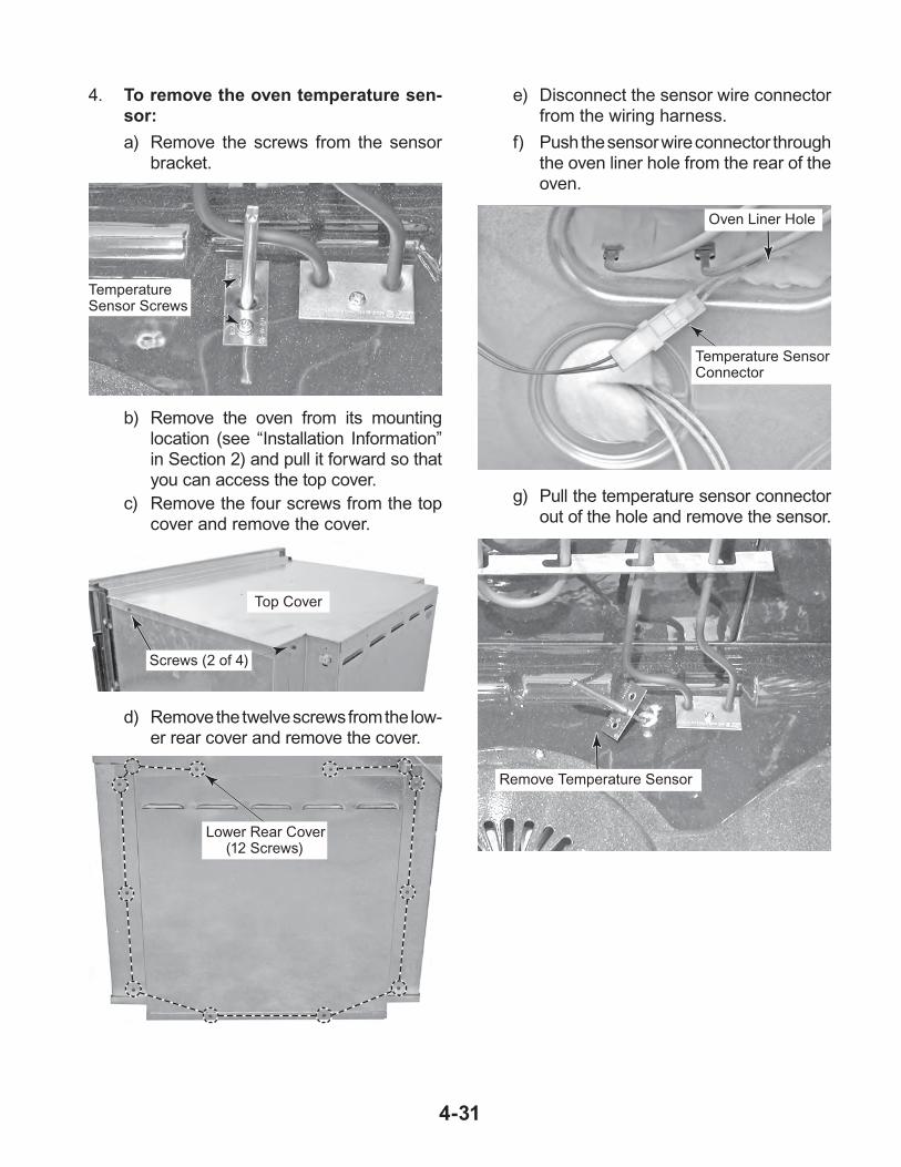
4. To remove the oven temperature sen-sor:
a) Remove the screws from the sensor bracket.
e) Disconnect the sensor wire connector from the wiring harness.
f) Push the sensor wire connector through the oven liner hole from the rear of the oven.
Temperature Sensor Screws
b) Remove the oven from its mounting location (see “Installation Information” in Section 2) and pull it forward so that you can access the top cover.
c) Remove the four screws from the top cover and remove the cover.
Lower Rear Cover(12 Screws)
Temperature Sensor Connector
g) Pull the temperature sensor connector out of the hole and remove the sensor.
Oven Liner Hole
Remove Temperature Sensor
Top Cover
Screws (2 of 4)
d) Remove the twelve screws from the low-er rear cover and remove the cover.

4-32
REMOVING THE CONVECTION RING ELEMENT AND THE CONVECTION FAN MOTOR
4. To remove the convection ring element:
a) Remove the two screws from the ele-ment brackets.
WARNING
1. Unplug oven or disconnect power.
2. Open the lower oven door.
3. Remove the seven screws from the con-vection cover and remove the cover.
Electrical Shock Hazard
Disconnect power before servicing.
Replace all parts and panels before operating.
Failure to do so can result in death or electrical shock.
Convection Ring Element & Fan Motor
7 Cover Screws
Ring Element Screws
Ring Element
b) Pull the convection ring element forward far enough to access the two wire con-nectors.
c) Disconnect the wire connectors from the convection ring element terminals and remove the element.
Ring Element Wires

4-33
5. To remove the convection fan motor:
a) Remove the 10mm hex nut from the convection fan blade (left-hand rotation) and remove the blade from the motor shaft.
Convection Fan Blade
Fan Blade Nut
b) Remove the three front screws from the convection fan motor.
Front Convection Fan Motor Screws
d) Remove the twelve screws from the low-er rear cover and remove the cover.
Lower Rear Cover(12 Screws)
Convection Fan Motor
e) Disconnect the red and yellow wires from the convection fan motor terminals.
f) Remove the two screws from the fan motor and remove the motor.
c) Remove the oven from its mounting location (see “Installation Information” in Section 2) and pull it forward so that you can access the rear covers.
RD
YL
Rear Motor Screws

4-34
REMOVING A HALOGEN LIGHT ASSEMBLY AND THE MEAT PROBE JACK
WARNING
1. Unplug oven or disconnect power.
2. Open the lower oven door.
Electrical Shock Hazard
Disconnect power before servicing.
Replace all parts and panels before operating.
Failure to do so can result in death or electrical shock.
3. To remove a halogen light assembly:
a) Remove the screw from the lens.
c) Remove the halogen bulb from the socket connector.
Meat Probe Jack
Halogen Lights
Lens Screw
Lens Clip
b) Unclip the lens from the socket and remove the lens.
d) Cut the wires near the socket body and splice the new socket in its place.
Halogen Bulb
Cut Socket Wires

4-35
4. To remove the meat probe jack:
a) Remove the nut from the meat probe jack.
Meat Probe Jack Nut
b) Remove the oven from its mounting location (see “Installation Information” in Section 2) and pull it forward so that you can access the meat probe jack access cover on the right side of the oven.
Meat Probe Jack Access Cover
c) Use a pair of side-cutters and cut the meat probe jack access cover from the right side cover (see the top right photo).
Remove Access Cover
d) Remove the meat probe jack from the right side cover.
e) Disconnect the wires from the meat probe jack terminals. NOTE: Make sure that you reinstall the star washer on the new jack when you install it.
Star Washer
Meat Probe Jack Wires
f) Mount the meat probe jack access cover to the side cover with two screws.
Meat Probe Jack Access Cover Screws

4-36
REMOVING THE BLOWER ASSEMBLY, BLOWER SPEED RESISTOR, AND OVEN SHUTDOWN THERMAL CUTOFF
WARNING
4. Remove the ten screws from the upper rear cover of the oven and remove the cover.
Electrical Shock Hazard
Disconnect power before servicing.
Replace all parts and panels before operating.
Failure to do so can result in death or electrical shock.
6. To remove the blower speed resistor:
a) Disconnect the two gray wires from the resistor terminals.
b) Remove the screw from the resistor bracket and remove the resistor.
Upper Rear Cover(10 Screws)
Top Cover
Screws (2 of 4)
1. Unplug oven or disconnect power.
2. Remove the oven from its mounting location (see “Installation Information” in Section 2) and pull it forward so that you can access the top cover.
3. Remove the four screws from the top cover and remove the cover.
Upper Rear Cover
Blower Speed Resistor
Blower Motor Oven Shutdown TCO
5. To remove the blower assembly:
a) Disconnect the white and gray wires from the blower motor terminals.
b) Remove the two screws from the blower brackets.
c) Pull back on the blower assembly while rotating it upwards and remove the as-sembly.
Blower Motor Wires
Screws
Blower Speed Resistor Wires
Screw
Blower
4-37
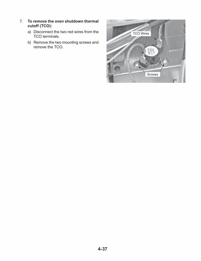
7. To remove the oven shutdown thermal cutoff (TCO):
a) Disconnect the two red wires from the TCO terminals.
b) Remove the two mounting screws and remove the TCO.
Screws
TCO Wires

4-38
REMOVING THE HIDDEN BAKE ELEMENT
WARNING
Electrical Shock Hazard
Disconnect power before servicing.
Replace all parts and panels before operating.
Failure to do so can result in death or electrical shock.
Top Cover
Screws (2 of 4)
1. Unplug oven or disconnect power.
2. Remove the oven from its mounting location (see “Installation Information” in Section 2) and pull it forward so that you can access the top cover.
3. Remove the four screws from the top cover and remove the cover.
4. Remove the twelve screws from the lower rear cover and remove the cover.
Lower Rear Cover(12 Screws)
5. Disconnect the two red wires from the hid-den bake element terminals.
6. Remove the four screws from the hidden bake element cover.
Hidden Bake Element Cover Screws
Red Wires
7. Bend the hidden bake element cover flaps down as far as possible.
8. Using a single-edge razor blade, cut the insulation blanket along the bracket edge of the hidden bake element. Spread the blanket apart so you can access the bracket screws.
Cut Insulation
9. Remove the four screws from the hidden bake element bracket.
Hidden Bake Element Bracket Screws

4-39
NOTE: When you remove the hidden bake element, press down on the front edge of the panel that is below the element so that it does not interfere with the removal.
10. Pull the hidden bake element out and re-move it from the bottom of the oven.
11. Remove the two bracket screws from the hidden bake element and remove the bracket from the element.
REASSEMBLY NOTE: When you install the replacement hidden bake element, press down on the front edge of the panel that is below the element so that it does not interfere with the installation. When installed, the edge of the panel should be below the element bracket so that the bracket fits flush against the chassis.
Hidden Bake Element Bracket Screws

4-40
REMOVING THE OVEN DOOR GLASS AND HANDLE1. Open the lower oven door.
2. Raise the two door hinge tabs to the “un-locked” position.
3. Close the oven door to within several inches, lift and pull out on the hinges, and remove them from the oven slots.
4. Place the oven door front side down on a padded surface to protect the finish.
5. Remove the two screws from each of the bottom corner glass holders and remove the holders.
6. To remove the inner oven door glass panels, lift each of the three glass panels, and remove them from the door.
Door Hinge Tab Locked (Down)
Door Hinge Tab Unlocked (Up)
Corner Glass Holder Screws
Inner Glass Panels
7. To remove the door handle and outer oven door glass:
a) Remove the three inner glass panels (see step 6).
b) Remove the three screws from the air vent and remove the vent.
Air Vent Screws
Oven Door Air Vent

4-41
c) Remove the four door handle bracket screws and remove the brackets and handle from the door.
d) Slide the bottom edge of the outer oven door glass out of the door frame and remove the glass.
Handle Brackets & Screws
Outer Door Glass
Door Frame

4-42
REMOVING THE OVEN DOOR GASKET1. Remove the lower oven door (see the pro-
cedure on page 4-40).2. Remove the screw from the door gasket
retainer and remove the retainer.
3. Pull the door gasket clips out of the oven liner holes and remove the gasket.
Gasket Retainer Screw
Gasket Clip
Door Gasket

5-1
COMPONENT TESTING
Electrical Shock Hazard
Disconnect power before servicing.Replace all parts and panels before operating.Failure to do so can result in death or electrical shock.
HUMIDITY SENSOR
WARNING
UPPER OVEN COMPONENTS
Refer to page 4-3 for the procedure for access-ing the humidity sensor.
1. Unplug oven or disconnect power.
2. Disconnect the humidity sensor wire con-nector (HUM) from the appliance manager board.
3. Set the ohmmeter to the R x 1K scale.
4. Touch the ohmmeter test leads to the humid-ity sensor connector pins 1 & 3, and 2 & 3. The meter should indicate approximately 2.8 KΩ @ 77°F (25°C).
Unplug oven or disconnect power.
Remove the lead wires from the related component before conducting any of the following tests.
Discharge the high-voltage capacitor and remove the lead wires from the primary wind-ing of the high-voltage transformer before conducting any of the following tests.
All operational checks using microwave en-ergy must be done with the microwave oven loaded with a minimum of 8 oz (250mL) of water in a microwave safe container.
•
•
•
•
Conduct a microwave energy test after per-forming any tests or repairs to the microwave oven.
Check that all wire leads are in the correct position before operating the microwave oven.
Grasp wire connectors when removing the wire leads from microwave to oven parts.
All testing must be done with an ohmmeter having a sensitivity of 20,000 ohms per volt DC or greater, and powered by at least a 9-volt battery.
•
•
•
•
Refer to page 4-3 for the procedure for access-ing the cavity thermostat.
1. Unplug oven or disconnect power.
2. Disconnect one of the wires from the cavity thermostat terminals.
3. Set the ohmmeter to the R x 1 scale.
4. Touch the ohmmeter test leads to the thermostat terminals. The meter should indicate a closed (0 Ω) circuit.
NOTE: The thermostat opens at 347°F (175°C).
CAVITY THERMOSTAT
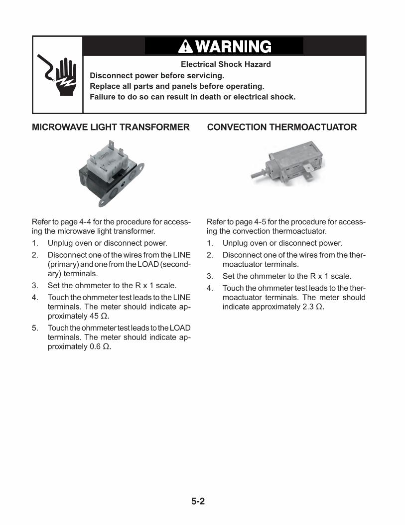
5-2
Refer to page 4-4 for the procedure for access-ing the microwave light transformer.
1. Unplug oven or disconnect power.
2. Disconnect one of the wires from the LINE (primary) and one from the LOAD (second-ary) terminals.
3. Set the ohmmeter to the R x 1 scale.
4. Touch the ohmmeter test leads to the LINE terminals. The meter should indicate ap-proximately 45 Ω.
5. Touch the ohmmeter test leads to the LOAD terminals. The meter should indicate ap-proximately 0.6 Ω.
CONVECTION THERMOACTUATORMICROWAVE LIGHT TRANSFORMER
Refer to page 4-5 for the procedure for access-ing the convection thermoactuator.
1. Unplug oven or disconnect power.
2. Disconnect one of the wires from the ther-moactuator terminals.
3. Set the ohmmeter to the R x 1 scale.
4. Touch the ohmmeter test leads to the ther-moactuator terminals. The meter should indicate approximately 2.3 Ω.
Electrical Shock Hazard
Disconnect power before servicing.Replace all parts and panels before operating.Failure to do so can result in death or electrical shock.
WARNING

5-3
Electrical Shock Hazard
Disconnect power before servicing.Replace all parts and panels before operating.Failure to do so can result in death or electrical shock.
WARNING
MONITOR FUSE
Refer to page 4-6 for the procedure for access-ing the monitor fuse.
1. Unplug oven or disconnect power.
2. Disconnect one of the wires from the fuse holder terminals.
3. Set the ohmmeter to the R x 1 scale.
4. Touch the ohmmeter test leads to the fuse holder terminals. The meter should indicate a closed circuit (0 Ω).
MICROWAVE DOOR INTERLOCK SWITCHES
Refer to page 4-7 for the procedure for access-ing the microwave door interlock switches.
1. Unplug oven or disconnect power.
2. Disconnect one of the wires from the door interlock switch terminals.
3. Set the ohmmeter to the R x 1 scale.
4. Touch the ohmmeter test leads to the COM and N.O. terminals of the door interlock switch. The meter should indicate an open circuit (infinite).
5. Press the actuator button on the interlock switch. The meter should indicate a closed circuit (0 Ω).
COM
N.O.

5-4
Electrical Shock Hazard
Disconnect power before servicing.Replace all parts and panels before operating.Failure to do so can result in death or electrical shock.
WARNING
MAGNETRONMAGNETRON THERMOSTAT
Refer to page 4-9 for the procedure for access-ing the magnetron thermostat.
1. Unplug oven or disconnect power.
2. Disconnect one of the wires from the mag-netron thermostat terminals.
3. Set the ohmmeter to the R x 1 scale.
4. Touch the ohmmeter test leads to the thermostat terminals. The meter should indicate a closed (0 Ω) circuit.
NOTE: The thermostat opens at 257°F (125°C) and closes at 185°F (85°C).
Refer to page 4-9 for the procedure for access-ing the magnetron.
1. Unplug oven or disconnect power.
2. Touch a screwdriver shaft to the filament wire terminals and the chassis.
3. Disconnect one of the wires from the mag-netron filament terminals.
4. Set the ohmmeter to the R x 1 scale.
5. Touch the ohmmeter test leads to the fila-ment terminals. The meter should indicate less than 1 Ω.
6. Touch one of the ohmmeter test leads to each of the filament terminals and the other lead to the chassis. The meter should indicate an open (infinite) circuit for both terminals.
Filament Terminals

5-5
Electrical Shock Hazard
Disconnect power before servicing.Replace all parts and panels before operating.Failure to do so can result in death or electrical shock.
WARNING
MAIN L1 & L2 FILTERS
Refer to page 4-11 for the procedure for ac-cessing the main L1 and L2 filters.
1. Unplug oven or disconnect power.
2. IMPORTANT: Discharge the main L2 filter by touching the leads of a 20,000 ohm resistor to the terminals and chassis ground.
3. Disconnect the wires from the main L1 or L2 filter terminals.
4. Set the ohmmeter to the R x 1 scale.
5. Touch the ohmmeter test leads to the fol-lowing L1 filter terminals:
Connectors P31 & P32, and P33 & P34 = 300 Ω or more (100 Ω or less is abnormal). Connectors P31 & P34, and P32 & P33 =
0 Ω (100K Ω or more is abnormal).
6. Touch the ohmmeter test leads to the fol-lowing L2 filter terminals:
Terminals 1 and 3 = less than 1 Ω.Terminals 2 and 4 = less than 1 Ω.Terminals 3 and 4 = 660 to 700 Ω.
1 2
43
GRILL & CONVECTION THERMOSTATS
Refer to page 4-11 for the procedure for ac-cessing the grill thermostat, and page 4-22 for the convection thermostat.
1. Unplug oven or disconnect power.
2. Disconnect one of the wires from the ther-mostat terminals.
3. Set the ohmmeter to the R x 1 scale.
4. Touch the ohmmeter test leads to the thermostat terminals. The meter should indicate a closed (0 Ω) circuit.
NOTE: The grill thermostat opens at 266°F (130°C) and closes at –31°F (–35°C).
The convection thermostat opens at 293°F (145°C) and closes at 221°F (105°C).
Convection Thermostat
Grill Thermostat
P34
P31
P33
P32
Main L2 Filter
Main L1 Filter

5-6
Electrical Shock Hazard
Disconnect power before servicing.Replace all parts and panels before operating.Failure to do so can result in death or electrical shock.
WARNING
MAGNETRON FAN MOTOR
Refer to page 4-13 for the procedure for ac-cessing the magnetron fan motor.
1. Unplug oven or disconnect power.
2. Disconnect one of the wires from the mag-netron fan motor terminals.
3. Set the ohmmeter to the R x 1 scale.
4. Touch the ohmmeter test leads to the mo-tor terminals. The meter should indicate approximately 3 Ω.
MICROWAVE INVERTER BOARD
Refer to page 4-13 for the procedure for ac-cessing the inverter.
1. Unplug oven or disconnect power.
2. Visually inspect connectors CN701, CN702, CN703, and E701 on the micro-wave inverter board and check for signs of overheating, or any failures due to loose wires, bad crimping, etc.
CN702
E701 CN703
CN701

5-7
Electrical Shock Hazard
Disconnect power before servicing.Replace all parts and panels before operating.Failure to do so can result in death or electrical shock.
WARNING
GRILL ELEMENT
Refer to page 4-16 for the procedure for ac-cessing the grill element.
1. Unplug oven or disconnect power.
2. Disconnect one of the wires from the grill element terminals.
3. Set the ohmmeter to the R x 1 scale.
4. Touch the ohmmeter test leads to the grill element terminals. The meter should indi-cate approximately 9 Ω.
LOWER OVEN LIGHT TRANSFORMER
Refer to page 4-20 for the procedure for ac-cessing the lower oven light transformer.
1. Unplug oven or disconnect power.
2. Disconnect one of the wires from the LINE (primary) and one from the LOAD (second-ary) terminals.
3. Set the ohmmeter to the R x 1 scale.
4. Touch the ohmmeter test leads to the LINE terminals. The meter should indicate ap-proximately 40 to 45 Ω.
5. Touch the ohmmeter test leads to the LOAD terminals. The meter should indicate less than 1 Ω.
LINE (Primary) Terminals
LOAD (Secondary) Terminals
Grill Element

5-8
Electrical Shock Hazard
Disconnect power before servicing.Replace all parts and panels before operating.Failure to do so can result in death or electrical shock.
WARNING
MICROWAVE CONVECTION RING ELEMENT
Refer to page 4-22 for the procedure for ac-cessing the microwave convection ring ele-ment.
1. Unplug oven or disconnect power.
2. Disconnect one of the wires from the con-vection ring element terminals.
3. Set the ohmmeter to the R x 1 scale.
4. Touch the ohmmeter test leads to the con-vection ring element terminals. The meter should indicate approximately 12 Ω.
MICROWAVE CONVECTION FAN MOTOR
Refer to page 4-22 for the procedure for ac-cessing the microwave convection fan motor.
1. Unplug oven or disconnect power.
2. Disconnect one of the wires from the con-vection fan motor terminals.
3. Set the ohmmeter to the R x 1 scale.
4. Touch the ohmmeter test leads to the fan motor terminals. The meter should indicate approximately 45 Ω.

5-9
Electrical Shock Hazard
Disconnect power before servicing.Replace all parts and panels before operating.Failure to do so can result in death or electrical shock.
WARNING
TURNTABLE MOTOR
Refer to page 4-24 for the procedure for ac-cessing the turntable motor.
1. Unplug oven or disconnect power.
2. Disconnect one of the wires from the turn-table motor terminals.
3. Set the ohmmeter to the R x 1K scale.
4. Touch the ohmmeter test leads to the turn-table motor terminals. The meter should indicate approximately 2450 Ω.
MEASURE OVEN INPUT CURRENTConnect an ammeter (Valhalla Scientific 2101 or equivalent recommended) to measure the input current of microwave oven when the power level is set to Level 10 at the touch panel.
If more than 0.5A:
The 900W inverter is probably OK. Check the magnetron. See Magnetron test on page 5-4.
If less than 0.5A:
There is no input to the 900W inverter.
Check the following:
1. Unplug oven or disconnect power.
2. No AC voltage supply. Check relay control board and wiring.
3. No control signal. Check relay control board and wiring.
15A
Amps

5-10
LOWER OVEN COMPONENTS
Electrical Shock Hazard
Disconnect power before servicing.Replace all parts and panels before operating.Failure to do so can result in death or electrical shock.
WARNING
DOOR LATCH ASSEMBLYRefer to page 4-28 for the procedure for ac-cessing the door latch assembly.
NOTE: The door latch assembly components will be tested at the appliance manager board (see page 4-18).
1. Unplug oven or disconnect power.
2. Set the ohmmeter to the R x 1K scale.
3. Touch the ohmmeter test leads to the wire connectors. The meter should indicate as shown below:
Latch Switch: P1-4 (TN) and P1-5 (BR). The meter should indicate an open circuit (infinite) with door unlocked, and a closed circuit (0 Ω) with the door locked.
Door Switch: P1-7 (OR) and P1-5 (BR). The meter should indicate an open circuit (infinite) with door unlocked, and a closed circuit (0 Ω) with the door locked.
Latch Motor: P8-5 (YL) and the neutral (WH) stud on the AC terminal block. The meter should indicate approximately 2450 Ω.
Lower Oven Appliance Manager
P8
P1
1 2 3 4 5 6 7
6 5 4 3 2 1

5-11
Electrical Shock Hazard
Disconnect power before servicing.Replace all parts and panels before operating.Failure to do so can result in death or electrical shock.
WARNING
BROIL ELEMENTRefer to page 4-30 for the procedure for ac-cessing the broil element.
NOTE: The broil element will be tested at the appliance manager board (see page 4-18).
1. Unplug oven or disconnect power.
2. Set the ohmmeter to the R x 1 scale.
3. Touch the ohmmeter test leads to the wire connectors. The meter should indicate as shown below:
Inner Element: T3-4 (OR) and T1-1 (RD). The meter should indicate between 31 and 36 Ω.
Outer Element: T3-1 (BU) and T2-2 (R/W). The meter should indicate between 53 and 59 Ω.
Lower Oven Appliance Manager
T3
OVEN TEMPERATURE SENSORRefer to page 4-30 for the procedure for ac-cessing the oven temperature sensor.
NOTE: The oven temperature sensor will be tested at the appliance manager board (see page 4-18).
1. Unplug oven or disconnect power.
2. Set the ohmmeter to the R x 1K scale.
3. Touch the ohmmeter test leads to P2-1 (V) and P2-2 (V). The meter should indicate approximately 1091 Ω @ 75°F (23.9°C).
P2
Lower Oven Appliance Manager
T1 1 2
1 2 3 4 5
1 2
3 4
5 6

5-12
Electrical Shock Hazard
Disconnect power before servicing.Replace all parts and panels before operating.Failure to do so can result in death or electrical shock.
WARNING
CONVECTION RING ELEMENTRefer to page 4-32 for the procedure for ac-cessing the convection ring element.
NOTE: The convection ring element will be tested at the appliance manager board (see page 4-18).
1. Unplug oven or disconnect power.
2. Set the ohmmeter to the R x 1 scale.
3. Touch the ohmmeter test leads to wire con-nectors T3-2 (YL) and T2-2 (R/W). The meter should indicate between 33 and 37 Ω.
Lower Oven Appliance Manager
T31 2 3 4 5
CONVECTION FAN MOTORRefer to page 4-32 for the procedure for ac-cessing the convection fan motor.
NOTE: The convection fan motor will be tested at the appliance manager board (see page 4-18).
1. Unplug oven or disconnect power.
2. Set the ohmmeter to the R x 1 scale.
3. Touch the ohmmeter test leads to wire connector P8-3 (OR) and the neutral (WH) stud on the AC terminal block. The meter should indicate approximately 18 Ω.
1 2 3 4 5 6
Lower Oven Appliance Manager
T2 2
P8

5-13
Electrical Shock Hazard
Disconnect power before servicing.Replace all parts and panels before operating.Failure to do so can result in death or electrical shock.
WARNING
MEAT PROBE JACKRefer to page 4-34 for the procedure for ac-cessing the meat probe jack.
NOTE: The meat probe jack will be tested at the appliance manager board (see page 4-18).
1. Unplug oven or disconnect power.
2. Set the ohmmeter to the R x 1 scale.
3. Touch the ohmmeter test leads to wire connectors P2-6 (WH) and P2-5 (OR). The meter should indicate approximately 78 Ω @ 60°F (15.6°C).
BLOWER MOTORRefer to page 4-36 for the procedure for ac-cessing the blower motor.
NOTE: The blower motor will be tested at the appliance manager board (see page 4-18).
1. Unplug oven or disconnect power.
2. Set the ohmmeter to the R x 1 scale.
3. Touch the ohmmeter test leads to wire connector P9-2 (GY) and the neutral (WH) wire at the AC terminal block. The meter should indicate between 181 and 240 Ω.
P2
1 2
3 4
5 6
Lower Oven Appliance Manager
1 2 3 4 5
Lower Oven Appliance Manager
P9

5-14
Electrical Shock Hazard
Disconnect power before servicing.Replace all parts and panels before operating.Failure to do so can result in death or electrical shock.
WARNING
BLOWER SPEED RESISTORRefer to page 4-36 for the procedure for ac-cessing the blower speed resistor.
NOTE: The blower speed resistor will be tested at the appliance manager board (see page 4-18).
1. Unplug oven or disconnect power.
2. Set the ohmmeter to the R x 1 scale.
3. Touch the ohmmeter test leads to wire con-nectors P9-2 (GY) and P8-4 (GY). The meter should indicate approximately 170 Ω.
OVEN SHUTDOWN THERMAL CUTOFF (TCO)Refer to page 4-36 for the procedure for ac-cessing the oven shutdown thermal cutoff.
NOTE: The oven shutdown thermal cutoff will be tested at the appliance manager board (see page 4-18).
1. Unplug oven or disconnect power.
2. Set the ohmmeter to the R x 1 scale.
3. Touch the ohmmeter test leads to wire con-nectors T1-2 (R/W) and P7-3 (RD). The meter should indicate a closed circuit (0 Ω).
Lower Oven Appliance Manager
P9
Lower Oven Appliance Manager1 2 3 4 5 6
P8
T1 1 2
1 3
P7
1 2 3 4 5

5-15
Electrical Shock Hazard
Disconnect power before servicing.Replace all parts and panels before operating.Failure to do so can result in death or electrical shock.
WARNING
HIDDEN BAKE ELEMENT Refer to page 4-38 for the procedure for ac-cessing the hidden bake element.
NOTE: The hidden bake element will be tested at the appliance manager board (see page 4-18).
1. Unplug oven or disconnect power.
2. Set the ohmmeter to the R x 1 scale.
3. Touch the ohmmeter test leads to wire con-nectors T3-3 (RD) and T1-1 (RD). The meter should indicate between 26 and 30 Ω.
Lower Oven Appliance Manager
T31 2 3 4 5
T1
1 2

5-16
— NOTES —

6-1
DIAGNOSTICS & TROUBLESHOOTING
IMPORTANT
Electrostatic Discharge (ESD) Sensitive Electronics
ESD problems are present everywhere. ESD may damage or weaken the elec-tronic control assembly. The new control assembly may appear to work well after repair is finished, but failure may occur at a later date due to ESD stress.
Use an anti-static wrist strap. Connect wrist strap to green ground connection point or unpainted metal in the appli-ance.
-OR-
Touch your finger repeatedly to a green ground connection point or unpainted metal in the appliance.
Before removing the part from its pack-age, touch the anti-static bag to a green ground connection point or unpainted metal in the appliance.
Avoid touching electronic parts or termi-nal contacts; handle electronic control assembly by edges only.
When repackaging failed electronic con-trol assembly in anti-static bag, observe above instructions.
•
•
•
•
DIAGNOSTICSIs oven in “Sabbath Mode”? If so “SAB” will appear in the digital display. Press OPTIONS and “7” to end Sabbath mode. This will return to BAKE mode for an untimed bake.
Disconnect power and perform the following checks:
A potential cause of a control not function-ing is corrosion on connections. Observe connections and check for continuity with an ohmmeter.
All tests/checks should be made with a VOM or DVM having a sensitivity of 20,000 ohms per volt DC or greater.
Check all connections before replacing com-ponents, looking for broken or loose wires, failed terminals, or wires not pressed into connectors far enough. Damaged harness must be entirely replaced. Do not re-work a harness.
Voltage checks must be made with all con-nectors attached to the boards.
Resistance checks must be made with power cord unplugged from outlet, and with wiring harness or connectors disconnected.
•
•
•
•
•
•
Electrical Shock Hazard
Disconnect power before servicing.
Replace all parts and panels before operating.
Failure to do so can result in death or electrical shock.
WARNING

6-2
PRECAUTIONS TO BE OBSERVED BEFORE AND
DURING SERVICING TO AVOID POSSIBLE EXPOSURE TO
EXCESSIVE MICROWAVE ENERGYa. Do not operate or allow the oven to be
operated with the door open.
b. Make the following safety checks on all ovens to be serviced before activating the magnetron or other microwave source, and make repairs as necessary:
1. Interlock Operation2. Proper Door Closing3. Seal and Sealing Surfaces (Arcing,
Wear and Other Damage)4. Damage to or Loosening of Hinges
and Latches5. Evidence of Dropping or Abuse
c. Before turning on microwave power for any service test or inspection within the microwave generating compartments, check the magnetron, waveguide or transmission line and cavity for proper alignment, integrity and connections.
d. Any defective or misadjusted components in the interlock, monitor, door seal, and microwave generation, and transmission systems shall be repaired, replaced, or adjusted by procedures described in ser-vice manual before the oven is released to the owner.
e. A microwave leakage check to verify compliance with the Federal performance standard should be performed on each oven prior to release to the owner.
f. Do not attempt to operate the oven if the door glass is broken.
FAILURE / ERROR DISPLAY CODESBefore proceeding with any corrective action, perform the following steps to enter the Diag-nostic mode.
1. Press the OFF key.
2. Press the OFF key.
3. Press the START key. If control does not enter Diagnostics, repeat steps.
Screen 1:
A. Main clock hours display shows latch state in first display position, and door state in second position.
B. Main clock minutes display show the model select state associated with control system.
C. Main temperature display shows the cavity temperature.
D. Lower text line shows software versions for appliance manager (AM), user interface (UI) and EEPROM version.
Press key #6 to scroll to next screen.
Screen 2:
Screen displays programmed cavity size. Press key #6 to scroll to next screen.
Screen 3:
Displays the last error code in memory. If GOOD is displayed there is not an error coded in memory.
To Clear Last Error Code
A. Unplug oven or disconnect power.
B. Wait 10 seconds, reconnect or plug in oven.
C. Enter Diagnostics mode by pressing OFF, OFF, START.
D. Press key #6 to show cavity size select screen.
E. Press key #6 to show error code.
F. To edit press CLOCK key
G. Press START key to clear last error. Control should display GOOD.
Troubleshooting Key strokes
Press the Bake key activates Bake relay.
Press Broil key once to activate Outer Broil, press again for Inner Broil.
Press Convect Bake key activates Convect Ring and Fan.
Press Self Clean key activates Latch Motor.
Press Cook time key once to activate low speed, press again for high speed.
•
•
•
•
•

6-3
Electrical Shock Hazard
Disconnect power before servicing.
Replace all parts and panels before operating.
Failure to do so can result in death or electrical shock.
WARNING
FAILURE(Leftmost2 ClockDigits)
ERROR(Rightmost
2 ClockDigits)
MESSAGE/DESCRIPTION
SUGGESTED CORRECTIVE ACTION PROCEDURE
F0Default
E0No failure (GOOD)
F1Component
E0 CHECK OVEN USER INTERFACE
PROCEDURE: Before proceeding, press OFF, OFF, START to enter theDiagnostic mode.A. Unplug oven or disconnect power.B. Replace oven user interface board.C. Replace all parts and panels before operating.D. Plug in oven or reconnect power.E. Verify operation is normal. Go to step 1 and complete checks.
F1Component
E1 CHECK OVEN APPLIANCE MANAGER
PROCEDURE: Before proceeding, press OFF, OFF, START to enter theDiagnostic mode.A. Unplug oven or disconnect power.B. Check oven door switch. If OK, go to step C.C. Replace oven appliance manager.D. Replace all parts and panels before operating.E. Plug in oven or reconnect power.F. Verify operation is normal. Press OFF, OFF, START to reenter the Diagnostic
Mode and complete checks.
F1Component
E2 CHECK MICROWAVE USER INTERFACE
PROCEDURE: Before proceeding, press OFF, OFF, START to enter theDiagnostic mode.A. Unplug oven or disconnect power.B. Replace microwave user interface.C. Replace all parts and panels before operating.D. Plug in oven or reconnect power.E. Verify operation is normal. Press OFF, OFF, START to reenter the Diagnostic
Mode and complete checks.
F1Component
E3 CHECK MICROWAVE APPLIANCE MANAGER
PROCEDURE: Before proceeding, press OFF, OFF, START to enter theDiagnostic mode.A. Unplug oven or disconnect power.B. Replace microwave appliance manager.C. Replace all parts and panels before operating.D. Plug in oven or reconnect power.E. Verify operation is normal. Press OFF, OFF, START to reenter the Diagnostic
Mode and complete checks.
FAILURE(Leftmost2 ClockDigits)
ERROR(Rightmost
2 ClockDigits)
MESSAGE/DESCRIPTION
SUGGESTED CORRECTIVE ACTION PROCEDURE
F1Component
E4 CHECK MICROWAVE POWER RELAY
PROCEDURE: Before proceeding, press OFF, OFF, START to enter theDiagnostic mode.A. Unplug oven or disconnect power.B. Replace microwave power relay.C. Replace all parts and panels before operating.D. Plug in oven or reconnect power.E. Verify operation is normal. Press OFF, OFF, START to reenter the Diagnostic
Mode and complete checks.
F1Component
E5 CHECK MICROWAVE INVERTER
PROCEDURE: Before proceeding, press OFF, OFF, START to enter theDiagnostic mode.A. Unplug oven or disconnect power.B. Replace microwave inverter.C. Replace all parts and panels before operating.D. Plug in oven or reconnect power.E. Verify operation is normal. Press OFF, OFF, START to reenter the Diagnostic
Mode and complete checks.
F1Component
E6 CHECK MICROWAVE WAVE GUIDE
PROCEDURE: Before proceeding, press OFF, OFF, START to enter theDiagnostic mode.A . U nplug oven or disconnect power.B. Replace microwave wave guide.C. Replace all parts and panels before operating.D. Plug in oven or reconnect power.E. Verify operation is normal. Press OFF, OFF, START to reenter the Diagnostic
Mode and complete checks.
F2Keypad
E0E1
KEYPAD DISCONNECTED
STUCK OR SHORTED KEY
PROCEDURE: Before proceeding, press OFF, OFF, START to enter theDiagnostic mode.A. Unplug oven or disconnect power.B. Check keypad connector for firm connection.C. Replace all parts and panels before operating.D. Plug in oven or reconnect power.E. If error code returns after 60 seconds proceed to step F.F. Unplug oven or disconnect power.G. Replace keypad.

6-4
FAILURE(Leftmost2 ClockDigits)
ERROR(Rightmost
2 ClockDigits)
MESSAGE/DESCRIPTION
SUGGESTED CORRECTIVE ACTION PROCEDURE
H. Replace all parts and panels before operating.I. P lug in oven or reconnect power. Wait 60 seconds.
J. If error code returns after 60 seconds, proceed to step K.K. Unplug oven or disconnect power.L. Replace cable connecting user interface and keypad.M. Replace all parts and panels before operating.N. Plug in oven or reconnect power. Wait 60 seconds.O. If error code returns after 60 seconds, proceed to step P.P. Unplug oven or disconnect power.Q. Replace oven user interface.R. Replace all parts and panels before operating.S. Plug in oven or reconnect power. Wait 60 seconds.T. Verify operation is normal. Press OFF, OFF, START to reenter the Diagnostic
Mode and complete checks.
F3Sensors
E1E3
LOWER MAIN OVEN SENSOR SHORTED OR OPEN
MEAT PROBE SHORTED
PROCEDURE: Before proceeding, press OFF, OFF, START to enter theDiagnostic mode.A. Verify cavity temperature on Screen 1.B. If dashes appear in main temperature display go to step C.C. Unplug oven or disconnect power.D. Remove back panels and ensure the indicated temperature sensor is plugged
in properly and fully inserted. If not, plug in the connector and proceed to step I.If sensor is plugged in properly go to step E.
E. Check connector P2 on the appliance manager. Ensure P2 connector isplugged in properly and fully inserted. If connector is inserted properly go tostep I. If not go to step F.
F. Visually inspect the wires between P2 on the appliance manager and theindicated temperature sensor. Make sure the wires are not pinched or cut. Ifwires appear intact, unplug P2 connector on the appliance manager.Go to step G.
G. Measure the indicated sensor resistance value (measure between appropriateP2 connector pins). For the following sensors, the resistance value should read:LowerOvenSensor: Between 931 and 2869 Ω (Approx.1080 Ω at room temp.)Meat Probe Sensor: Between 1,300 and 103,000 Ω (Approx. 59,000 Ω at room temp.)
(Insert meat probe into meat probe jack locatedinside the oven cavity prior to reading resistance.)
If indicated temperature sensor does not meet these requirements go to step H.If indicated temperature sensor does meet these requirements go to step J.
H. For LOWER sensor:Replace appropriate temperature sensor. Repeat step G.
If the requirements are not met, replace sensor harness. Repeat step G.For MEAT PROBE sensor:Replace meat probe sensor. Repeat step G.
If the requirements are not met, replace sensor harness. Repeat step G.If the requirements are still not met, replace the meat probe jack.If the meat probe sensor is still not operating correctly go to step I.
I. Replace the appliance manager. Ensure all connectors are properly placed andfirmly connected.
J. Replace all parts and panels before operating.K. Plug in oven or reconnect power. Wait 60 seconds.L. Enter into Diagnostic mode and read sensor for main oven sensor, warm drawer
and meat probe on immediate display.
F3Sensors
E2 WARMING DRAWER SENSOR SHORTED OR OPEN
PROCEDURE: Oven is not equipped with this feature. If error occurs press OFF,OFF, START enter into Diagnostics Mode, then replace user interface with correctcontrol associated with this product.
F4MicrowaveSensors
E1E2E4
CAVITY TEMPERATURE SENSOR ERROR
INTERNAL TEMPERATURE SENSOR
HUMIDITY SENSOR
FAILURE(Leftmost2 ClockDigits)
ERROR(Rightmost
2 ClockDigits)
MESSAGE/DESCRIPTION
SUGGESTED CORRECTIVE ACTION PROCEDURE
PROCEDURE: There are three sensors for the microwave. They are the CavitySensor, Ambient Sensor (integrated on the MW appliance manager), and HumiditySensor. Before proceeding, press OFF, OFF, START to enter the Diagnostic mode.A. Press the number "6" key to transition to the Sensors screen.B. Verify in diagnostics the temperature readings on sensor.C. The sensors for the combo microwave oven will scroll through the list of sensors.D. If a sensor reading on the display shows (---) dashes, the sensor is not
connected or otherwise inoperable. If sensor that shows dashes is theambient sensor, proceed to step O.
E. Unplug oven or disconnect power.F. Remove top panel to gain access to the microwave control system.G. Ensure the cavity temperature sensor (P6) and the humidity sensor (P4) are
plugged in properly to the appliance manager. If not, plug in the connectorand proceed to step R. If connectors are plugged in proceed to step H.
H. Visually inspect the wires between P4 and cavity sensor from the appliancemanager to the back of the unit to ensure they are not pinched or cut. Ifwires appear to be intact, unplug connector and proceed to step I.
I. Measure the indicated sensors resistance value from the P4 connector. Forthis sensor, the resistance value should read 231 kΩ at 25°C.
J. Visually inspect the wires between P6 and humidity sensor from the appliancemanager to the front of the unit to ensure they are not pinched or cut. If wiresappear to be intact, unplug connector and proceed to step K.
K. Measure the indicated sensors resistance value from the P6 connector. For thissensor, the resistance value should read 2.8 kΩ at 25°C (between pins 3 and 1or between pins 3 and 2).
L. If indicated temperature sensor does not meet these requirements proceed to step M.M. Replace cavity sensor. Ensure the cavity sensor is properly inserted and
plugged into P6. Continue to step P.N. Replace humidity sensor. Ensure the humidity sensor is properly inserted and
plugged into P4. Continue to step P.O. Replace microwave appliance manager. Ensure all connectors are properly
placed and firmly connected.P. Replace all parts and panels before operating.Q. Plug in oven or reconnect power. Wait for 60 seconds.R. Enter into the Diagnostic Mode and press key "6" to scroll to the sensor display.
Read the sensor reading for the three sensors, ensuring the cavity, humidityand internal sensors are reading correctly.
F5NONE IDENTIFIED FOR MICROWAVE METHOD FORDETERMINING FAILURE
PROCEDURE: Before proceeding, press OFF, OFF, START to enter DiagnosticMode. Using the main screen upon entering diagnostics open and close door onmicrowave. In the hours field, the second digit should show "0" when door is openand "1" when door is closed. If display shows a "0" when door is closed and does nottransition to a "1", verify position of door switches and replace as necessary.
F5E0E1
DOOR AND LATCH SWITCH DO NOT AGREE
DOOR LATCH NOT OPERATING.
PROCEDURE: Before proceeding, press OFF, OFF, START to enter the Diagnostic mode.
TO VERIFY DOOR SWITCH:A. While in diagnostics, open the oven door. The second digit on the clock display
should toggle between “1” and “0” as the door opens and closes. When door isclosed display should show “1”, when the door is open display should show “0”.
If the second digit on the clock display did not toggle, go to step B.If the digit did not toggle after replacing the door switch, go to step D.If the digit did not toggle after replacing the door switch harness, go to step F.
B. Unplug oven or disconnect power.C. Replace door switch. (If door switch is integral to the door/latch motor
assembly, replace the entire door/latch motor assembly). Go to step H.D. Unplug oven or disconnect power.E . C heck the integrity of the harness wires and connections between the
appliance manager and the door/latch assembly. Ensure there are no shortedor pinched wires.
If the wiring harness is pinched or damaged, replace the door switch harness.Go to step H.If wiring harness is good, go to step H.
F. Unplug oven or disconnect power.G. Replace appliance manager. Go to step H.H. Replace all parts and panels before operating.I. P lug in oven or reconnect power.
J. Press OFF, OFF, START to reenter Diagnostic mode. Repeat step A.

6-5
FAILURE(Leftmost2 ClockDigits)
ERROR(Rightmost
2 ClockDigits)
MESSAGE/DESCRIPTION
SUGGESTED CORRECTIVE ACTION PROCEDURE
TO VERIFY DOOR LATCH SWITCH/MOTOR ASSEMBLY:A. While in diagnostics, press the CLEAN key within the first 120 seconds of power
up to cycle the latch motor to the locked position. “1” should display in the firstclock digit from the left when locked. Press the CLEAN key to cycle the latchmotor to the unlocked position. The first clock digit should toggle to “0” when thedoor is unlocked.
If the digit did not toggle, go to step B.If motor runs continuously, wait until motor reaches the unlocked position, openthe door and press the OFF key. Go to step B.If motor did not run go to step H.If the digit did not toggle after replacing the door latch motor assembly, go to step D.If the digit did not toggle after replacing the door switch harness, go to step F.If the digit did toggle, door latch switch is operating correctly.
B. Unplug oven or disconnect power.C. Replace door latch motor assembly. Go to step K.D. Unplug oven or disconnect power.E. Check the integrity of the harness wires and connections between the
appliance manager and the door/latch assembly. Ensure there are no shortedor pinched wires.
If the wiring harness is pinched or damaged, replace the door switch harness.Go to step H.If wiring harness is good, go to step H.
F. Unplug oven or disconnect power.G. Replace appliance manager. Go to step H.H. Replace all parts and panels before operating.I. P lug in oven or reconnect power.
J. Press OFF, OFF, START to reenter Diagnostic mode. Repeat step A.
F6System
E0 LOST COMMUNICATIONS
PROCEDURE: Before proceeding, press OFF, OFF, START to enter Diagnosticmode. Ensure AM software, UI software and EEPROM CHECKSUM versions appearon the lower text line. If AM software and EEPROM versions do not appear, UI andAM may not be communicating. Verify this for the lower oven UI and for themicrowave (upper oven) UI. The lower oven UI will show the AM software version forthe lower oven appliance manager, and the microwave UI will show the AM softwareand EEPROM versions for the microwave appliance manager.
If the lower oven UI is not displaying the AM software version, go to UI IS NOTDISPLAYING AM SOFTWARE VERSION.If the upper oven UI is not displaying the AM software and EEPROM versions,go to UPPER OVEN UI IS NOT DISPLAYING THE AM SOFTWARE ANDEEPROM VERSIONS.If lower oven UI and microwave UI are both displaying an error, go to LOWEROVEN UI AND MICROWAVE UI ARE BOTH DISPLAYING AN ERROR.
UI IS NOT DISPLAYING AM SOFTWARE VERSIONA. Unplug oven or disconnect power.B. Open the back panels and make sure the P6 and P2 connectors are fully
inserted on the appliance manager and on the lower oven user interface board.- I f they are not plugged in, plug in connectors and go to step F.- I f they are plugged in, go to step C.
C. Visually inspect all wires between P6 on the appliance manager and P2 on thelower user interface.- M ake sure wires are not cut or pinched.- I f the wires appear to be intact, perform a continuity check between
P6-1 of the appliance manager and P2-1 of the user interface board.Complete for P6-2(AM) to P2-2(UI), P6-4(AM) to P2-4(UI) and P6-5(AM) toP2-5(UI). All the measurements made should be less than 5 Ω. If any ofthese measurements exceeds 5 Ω, go to step E.
D. Replace the appliance manager. Ensure all connectors are properly inserted.E. Replace the wiring harness (signal). Ensure all connectors are properly inserted.F. Replace all parts and panels before operating.G. Plug in oven or reconnect power.H. Observe for longer than 1 minute to determine if error has been repaired.I. If error does not appear, initiate a bake cycle. Let the cycle run for at least
1 minute.- I f n o e rror occurs, cancel the cycle, the problem has been repaired.- I f e rror occurs again, restart the troubleshooting procedure at step A.
At step D, replace the lower oven user interface board if appliancemanager has already been replaced.
- I f both are replaced the problem has been repaired.
FAILURE(Leftmost2 ClockDigits)
ERROR(Rightmost
2 ClockDigits)
MESSAGE/DESCRIPTION
SUGGESTED CORRECTIVE ACTION PROCEDURE
UPPER OVEN UI IS NOT DISPLAYING THE AM SOFTWARE AND EEPROMVERSIONSA. Unplug oven or disconnect power.B. Open the back panels and make sure the P2 and U3 connectors are fully
inserted on the microwave user interface and the wide interface board. Makesure the P1 connector on the wide interface board and the P10 connector onthe microwave oven appliance manager are inserted.- I f the P2 (mwo UI) and U3 (wide interface board) are plugged in, go to step C.- I f the P2 (mwo UI) to U3 (wide interface board) connectors are not connected,
plug in the connectors and proceed to step F.If the P1 (wide interface board) to P10 (microwave appliance manager)connectors are not connected, plug in the connectors and go to step F.If the P1 (wide interface board) to P10 (microwave appliance manager) areplugged in, go to step D.
C. Visually inspect all wires between P2 on the microwave user interface and U3on the wide interface board. Make sure the wires are not cut or pinched.
If the wires appear to be intact, perform a continuity check between P2-1 andU3-1 of the microwave user interface (mwo UI) and the wide interface board.Complete for P2-2 (mwo UI) to U3-2 (wide interface board), P2-4 (mwo UI) toU3-4 (wide interface board), and P2-5 (mwo UI) to U3-5 (wide interface board).All the measurements should be less than 5 Ω .- I f any of these measurements exceeds 5 Ω, replace the wiring harness
(signal). Ensure all connectors are properly inserted and go to step H.- If the measurements are less than 5 Ω, reconnect P2 and go to step D.
D. Visually inspect all wires between P1 on the wide interface board and P10 onthe microwave appliance manager. Make sure the wires are not cut or pinched.If the wires appear to be intact, perform a continuity check between P1-1 on thewide interface board to P10-1 on the microwave appliance manager, continuingfor P1-2 (wide interface board) to P10-2 (microwave appliance manager), P1-3to P10-3, P1-4 to P10-4, P1-5 to P10-5 and finally P1-6 to P10-6. All themeasurements should be less than 5 Ω.
If any of these measurements exceeds 5 Ω, go to step F.If the measurements are less than 5 Ω, reconnect P1 and go to step E.
E. Replace the wide interface board. Ensure all connectors are properly inserted.Go to step H. If the wide interface board has already been replaced and theerror has not been corrected, proceed to step G.
F. Replace wiring harness (between P1 and P10) and proceed to step H.G. Replace the microwave appliance manager. Ensure all connectors are properly
inserted. Go to step H.H. Replace all parts and panels before operating.I. Plug in oven or reconnect power.
J. Observe for longer than one minute to determine if error has been repaired.K. If error does not appear, initiate a microwave cycle. Let the cycle run for at
least 1 minute.- I f no error occurs, cancel the cycle, the problem has been repaired.- I f e rror occurs, restart the troubleshooting procedure at step A.
At step E, replace the microwave user interface board in the wideinterface board and/or microwave appliance manager have already beenreplaced.)
- I f both are replaced the problem has been repaired.
LOWER OVEN UI AND MICROWAVE UI ARE BOTH DISPLAYING AN ERRORA. Unplug oven or disconnect power.B. Open the back panels and make sure the P2 connector on the lower oven UI
and the P2 connector on the microwave UI and fully inserted.- I f they are not, plug the connectors in and go to step F.- I f they are plugged in, go to step C.
C. Visually inspect all the wires between P2 on the lower oven UI and P2 on themicrowave user interface. Make sure the wires are not cut of pinched. If thewires appear to be intact, perform a continuity check between P2-1 of the loweroven UI and P2-1 of the user interface board. Complete for P2-2 (lower oven UI)to P2-2 (microwave UI), P2-4 (lower oven UI) to P2-4 (microwave UI) and P2-5(lower oven UI) to P2-5(UI). All the measurements made should be lessthan 5 Ω.- I f any of these measurements exceeds 5 Ω, go to step E.- I f any measurements are less than 5 Ω, reconnect P2 and go to step D.
D. Replace the lower oven UI. Ensure all connectors are properly inserted.Go to step F.
E. Replace the wiring harness (signal) and proceed to step F.F. Replace all parts and panels before operating.G. Plug in oven or reconnect power.H. Observe for longer than 1 minute to determine if error has been repaired.I. If error does not appear, initiate a bake cycle. Let the cycle run for at
least 1 minute.- I f n o e rror occurs, cancel the cycle, the problem has been repaired.- I f e rror occurs again, restart the troubleshooting procedure at step A.
(Except in step D, replace microwave user interface board if lower oven UIhas already been replaced.)

6-6
FAILURE(Leftmost2 ClockDigits)
ERROR(Rightmost
2 ClockDigits)
MESSAGE/DESCRIPTION
SUGGESTED CORRECTIVE ACTION PROCEDURE
F6E1E2
COOK oven OVER TEMPERATURECLEAN oven OVER TEMPERATURE
PROCEDURE: Before proceeding, press OFF, OFF, START to enter the Diagnosticmode.A. If oven is off, turn oven on and inspect all of the elements, convect ring, bake
and broil. Visually inspect all elements to ensure they are not operating.B. Unplug oven or disconnect power. Wait 10 seconds.C . Enter into Diagnostics following steps 1 through 3 on from page 6-2.D . P ress the BAKE key to cycle the bake relay on and off as long as Diagnostics
mode is within the first 120 seconds of power up.E. If the bake relay does not cycle, proceed to step F.F. Unplug oven or disconnect power for 30 seconds.G. Plug in oven or reconnect power.H. Enter into Diagnostics by pressing OFF, OFF, START. Press the BAKE key and
cycle relay on and off.If the bake relay does not cycle on and off, go to step O.If the element does not cycle with the relay, go to step M.If the element does cycle on and off, go to step I.
I. P ress the BROIL key, while in Diagnostics mode, to cycle the broil relays. PressBROIL key one time for outer broil element. Ensure outer broil relay energizes byinspecting the outer broil element. Press BROIL key again for inner broil element.Ensure inner broil relay energizes by inspecting the inner broil element.
If broil relay does not turn on and off, go to step O.If the element does not cycle with the relay, go to step M.If the element does cycle on and off, go to step J.
J. Press the CONVECT key, while in Diagnostics mode, to cycle the convect relayon and off.
K. If the convect relay does not turn on and off, go to step O.L. If the element does not cycle with the relay, go to step M.M. Unplug oven or disconnect power.N. Check integrity of all harness wires and connections between the appliance
manager and the electrical elements. Ensure all wiring and connections betweenthe appliance manager and elements, and the appliance manager and userinterface are intact and properly seated and that no wires are shorted ordamaged.
O. Unplug oven or disconnect power.P . Replace the appliance manager. Go to step S.Q. Replace user interface board. Go to step S.R. Replace the harness.S. Replace all parts and panels before operating.T. Plug in oven or reconnect power.U. Verify operation is normal. Press OFF, OFF, START to reenter Diagnostic mode
and complete checks.
F6 E3MINI OVEN/WARM DRAWER OVER
TEMPERATURE
PROCEDURE: Oven is not equipped with this feature. If error occurs, beforeproceeding press OFF, OFF, START enter into Diagnostics mode, then replace userinterface with correct control associated with this product.
FAILURE(Leftmost2 ClockDigits)
ERROR(Rightmost
2 ClockDigits)
MESSAGE/DESCRIPTION
SUGGESTED CORRECTIVE ACTION PROCEDURE
F6 E4USER INTERFACE/
APPLIANCE MANAGER MISMATCH
PROCEDURE: Before proceeding, press OFF, OFF, START to enter the Diagnosticmode.A. Unplug oven or disconnect power. Wait for 10 seconds.B. Plug in oven or reconnect power.C. Enter into Diagnostics mode by pressing OFF, OFF, START.D. Press BAKE. Ensure bake relay energizes by inspecting bake element.E. Press BROIL one time for outer broil element. Ensure outer broil relay energizes
by inspecting the outer broil element.F. Press BROIL again for inner broil element. Ensure inner broil relay energizes by
inspecting the inner broil element.G. Press SELF CLEAN to drive door latch to lock door. Press again to reset the door
latch to normal state.H . P ress COOK to activate the low speed cooling fan. Press again for high speed.I. If all functions are working, the AM and UI are properly working.
J. Exit Diagnostics by pressing OFF.K . Press BAKE and ensure that bake relay energizes and the control enters the
bake preheat. Wait up to 60 seconds to ensure error has been resolved. If errorreturns, proceed to step L.
L. Unplug oven or disconnect power.M. Remove covers for access to oven controls.N. Replace the appliance manager. Ensure all connections are properly seated. Go
to step O.O. Replace all parts and panels before operating.P. Plug in oven or reconnect power.Q. Press BAKE and ensure the bake relay energizes and the control enters into
bake/preheat. Wait up to 60 seconds to ensure error has been resolved.If error returns, go to step R.
R. Replace the user interface. Ensure all connections are properly seated. Go tostep S.
S. Replace all parts and panels before operating.T. Plug in oven or reconnect power.U. Press BAKE and ensure the bake relay energizes and the control enters into
bake/preheat. Wait up to 60 seconds to ensure error has been resolved.
F6 E5 NO CAVITY SIZE COMMAND
PROCEDURE: Before proceeding, press OFF, OFF, START to enter Diagnosticsmode. Control should immediately power up in cavity size select mode. Using key #6(down) and key #3 (up) scroll through to locate the corresponding cavity size. Oncelocated, press the start key to accept the proper cavity size for the unit beingprogrammed. Control should reinitialize to cavity size selected. If error returns at least60 seconds after cavity size has been set, go to step A.A. Unplug oven or disconnect power. Wait 10 seconds.B. Plug in oven or reconnect power.C. Enter into Diagnostics mode by pressing OFF, OFF, START. Press #6
(down) once main diagnostics screen appears. Screen should identify cavitysize for unit being programmed. If this is incorrectly shown, press CLOCK toedit current programmed size. Press #6 (down) to locate the proper cavity size.Once located, press START to accept the new cavity size. Control will resetand initialize the new cavity size programmed. Wait for 60 seconds to ensureerror has been corrected.
If error is corrected, replace all parts and panels before operating.If error returns, proceed to step D.
D. Unplug oven or disconnect power.E. Replace user interface oven control ensuring all connections are properly seated
and go to step F.F. Replace all parts and panels before operating.G. Plug in oven or reconnect power.H. Control may power up in cavity size select mode. Set cavity size as outlined in
step C by locating proper cavity size and pressing START once located.I. Wait for at least 60 seconds to ensure error has been corrected.

6-7
FAHRENHEIT (° F) TO CELSIUS (° C) CONVERSIONThe temperature is preset in Fahrenheit, how-ever it can be changed to Celsius.
To Change: Press OPTIONS and then “1” to toggle temperature between Fahrenheit and Celsius settings.
When in Fahrenheit, “°F” follows the oven temperature.
When in Celsius, “°C” follows the oven tem-perature.
ADJUST OVEN TEMPERATURE CALIBRATION1. Press OPTIONS and then “6” to set the
calibration.
2. On double oven only, press UPPER OVEN or LOWER OVEN to select oven.
Each oven calibration can be independently set.
3. Press “3” to increase and “6” to decrease the temperature.
4. Press START to end calibration.
PROGRAMMING THE CAVITY SIZEA. Unplug oven or disconnect power.
B. Wait 10 (ten) seconds, plug in oven or re-connect power.
C. Enter Diagnostics mode by pressing OFF, OFF, START.
D. Press key #6 to show cavity size select screen.
E. To edit press CLOCK key.
F. Scroll through cavity sizes by pressing key #6 until size required is displayed.
G. Once correct size is displayed, press the START key to accept modification.
KEYPADS
Door switch state
Latch switch state
Main CavityTemperature Secondary
cavity temperature
Meat probetemperature
Warm drawertemperature(if applicable)
Model select state
Lower scrolling text line
Upperscrollingtext line
Sensortemperaturedisplay
Door switch state
Modelselect state
Model Select State Description
02 27" Combo Microwave Upper/Thermal Convection Lower
01 30" Combo Oven Microwave Upper/Thermal Convection Lower

6-8
MW OVEN POWER OUTPUT TESTThe power output of the magnetron can be mea-sured by the following tap water temperature rise test.
NOTES:
Be sure oven cavity is clean and cool (not used recently).
The magnetron output will be lower with lower line voltages.
1. Fill a glass beaker with 10 oz. (300mL) of tap water. Stir the water with a thermometer (digital recommended) and record the tem-perature. This starting temperature of the water should be between 50°F and 75°F (10°C and 24°C).
2. Place the beaker and water in the center of the microwave oven. Operate on HIGH power level for 30 seconds.
3. When the microwave oven is finished, stir the thermometer through the water and record the temperature.
4. Subtract the cold water temperature from the warm water temperature to get the tem-perature rise. Normal range is as shown in the following table.
•
•
Voltage(VAC under load) Temperature Rise
120V 20-27°F (11-15°C)
108V 18-27°F (10-15°C)
RELAY LOGIC - LOWER OVEN
RELAY LOGIC - MICROWAVE OVEN
NORTENGA
M
LLIRG
GNIR .VNOC
NAF .VNOC
NAFGNILOOC
ELBATNRUT LP
MA
SUPERBA
MICROWAVES FULL PWRMICROWAVES VAR. PWR
CUSTOM REHEATCUSTOM DEFROSTSOFTEN/MELTPOPCORN
STEAMCRISPEASY CONVECTCOOL DOWNOFF (DOOR CLOSED)DOOR OPEN (COOL DOWN)DOOR OPEN
SYALER
EKAB
LIORBNI
LIORBTUO
MELEVNOC
NAFVNOC
YALERBLD
TLNEVO
REWOLB
MODES
OFFBAKE PRE-BBAKE PRE-ABAKE SSCBAKE PRE-BCBAKE PRE-ACBAKE SSFBROIL PRE-BFBROIL PRE-AFBROIL SSINBROIL PRE-BINBROIL PRE-AINBROIL SSCBROIL PRE-BCBROIL PRE-ACBROIL SSCROAST PRE-BCROAST PRE-ACROAST SSBPROOF PRE-B
BPROOF PRE-ABPROOF SSDEHYDRATE PRE-BDEHYDRATE PRE-ADEHYDRATE SSCLEAN
L
LLLL
LLLLLLL
LLLLLLLL
LLLLH
ON (LOW SPEED)
ON (HIGH SPEED)L
H
OFF
ONCYCLING (MAXPERIOD: 60 SEC.)ON OR OFF
RELAY LOGIC KEY

7-1
WIRING DIAGRAM & STRIP CIRCUITSWIRING DIAGRAM
L1 N L2
BK W R
BK
W
R
LINE 20AFUSE BK
W
R
W
MAIN FILTER L11030
MAIN FILTER L21035
P32 P33
P31 P34
1
2
3
4
BR
W W
RY/G18
BK W W
W
R
BK
W
BK
BK
BK
BK
BU
HALOGEN LIGHT
MW LIGHTTRANSFORMER
BR
BR
R
R
BR
1620CONV
THERMISTOR
HUMIDITYSENSOR
1130CAVITY
THERMOSTAT
P6
P4
W BU BU 1 2
4SECONDARY
INTERLOCK SWITCH
P1-3 P10
P1WIDE INTERFACE BOARD
U3
P3-1 Y
MICROWAVE APPLIANCEMANAGER
MONITOR FUSE20A
BK BR
PRIMARY INTERLOCKSWITCH 1060
1 2
4BR 2
41 R
MONITORINTERLOCK SWITCHP2-6
P1-1
P2-5
P1-2
Y
Y
BU
P3-2P2-8P2-7P2-4P2-3P2-2P2-1
4904
49052
1
12
12
4903
P8-3P8-2P8-1
BKBK
BKBK
BRBR
CONV.THERMOACTUATOR
BK BK
CONV. FAN
MAGNETRON FAN
TURNTABLE
Y/G
BK
W GRILL 1600W
CONV. 1200W
CN701 MWINVERTER
CN702CN703
E70
W Y/G
BU
R RF FA
1020MAGENTRONTHERMOSTAT
MAGNETRONW
W
GND N L2
W R
CONVECTIONTHERMOSTAT
1170
BU
BK
1080GRILL
THERMOSTAT
P4
P3 P1 P2
KEYPAD
CONTROL POWER TRANSFORMER
R
W Y
LOWER DOORLOCK LATCH
BK
BK
MW UI BOARDLOWER OVEN UI BOARD
W V
W VW
W
OR
W
BR
BU BU
BR OR OR
T T
DOOR SWITCH(ON LATCH ASSY)
LATCH SWITCH(OPERATED BY MOTOR)
BK
Y
R/WG
EOL TESTERCONNECTION
BK
P6LOWER OVENAPPLIANCEMANAGER
P2-1P2-2P2-5P2-6T4-4T4-3
P1-5BR
P1-7
P1-4
P8-1
P8-5
P5-1P5-3P9-5
P7-3
P7-1
T3-2
T3-3
T3-4
T3-1
T1-1
T1-2
T2-2
P8-3
P8-6
P8-4
T1-2
P9-2
R
W
Y
R
OR
BU
R
R/W
R
R/W
OR
BK/W
GY
GY
CONV. 1600WY
RBAKE 2000W
IN BROIL 1800W OR
OUT BROIL 1450WBU
LOWER LIGHTTRANSFORMER
W
GYGY
BLOWER SPEEDRESISTOR
BLOWER
WW
CONV. FAN
HALOGEN LIGHT 5W BULBOPERATES IN ALL MODESEXCEPT SELF-CLEAN
BKBKBK
W
W
W
W
W
R
R
OVENSHUTDOWNTHERMALCUTOFF(NON-RESETTABLE)105°C (221°F)
MICROWAVE
LOWEROVEN
THERMAL CUTOFF(NON-RESETTABLE)
GROUND (CHASSIS)
PLUG WITH FEMALECONNECTOR
RECEPTACLE WITHMALE CONNECTOR
LIGHT
AC DRIVEMOTOR
RELAY COIL
RESISTOR
RELAYCONTACTS
HEATINGELEMENT
ENCLOSEDTHERMISTOR
OPERATEDBY DOOR THERMOSTAT
THERMOACTUATOR
THERMAL CUTOFF(MANUALLY
RESETTABLE)
SYMBOLS
NOTES:
• When replacing the electronic control, be sure to program thecavity size. See “Programming the Cavity Size” on page 6-7.
• Dots indicate connections or splices.
• Circuit shown in STANDBY/OFF mode with oven door closed.

7-2
STRIP CIRCUITSThe following individual circuits are for use in diagnosis, and are shown in the ON position. Do not continue with the diagnosis of the appliance if a fuse is blown, a circuit breaker is tripped, or if there is less than a 240 volt power supply at the wall outlet.
BAKE PREHEAT B - BAKE PREHEAT A - BAKE SS
L1
BK
BK
BK
T4-3
T4-4
P8-1
T3-3
T3-1
T3-4T2-1T2-2T1-1T1-2
P8-4
R
BU
ORRR/WRR/W
GY
BAKE 200W
OUT BROIL 1450W
IN BROIL 1800W
GY
N L2W R
WBLOWER
BLOWERSPEED RESISTOR
BUOR
BK
OVENSHUTDOWNTHERMALCUTOFF(NON-RESETTABLE)(105°C) (221°F)
M
L1BK T4-3
P8-1
T3-4
T1-1T1-2
P8-4
RR/W
IN BROIL1800W
GY
OROR
BLOWERSPEED RESISTOR
GY
L2R
NW OVEN
SHUTDOWNTHERMALCUTOFF(NON-RESETTABLE)(105°C) (221°F)W
BK
BK
BLOWERM
INNER BROIL PREHEAT B - INNER BROIL PREHEAT A - INNER BROIL SS
BLOWERSPEED RESISTOR
OVENSHUTDOWNTHERMALCUTOFF(NON-RESETTABLE)(105°C) (221°F)
L1BK
BK
BK T4-3
P8-1
T4-4T3-1
T3-4T1-1T1-2T2-1T2-2
P8-4
OUT BROIL 1450W
IN BROIL1800W
BU
OR
RR/W
GY
BU
OR
RR/W
GY
N L2W R
WBK
BLOWERM
FULL BROIL PREHEAT B - FULL BROIL PREHEAT A - FULL BROIL SS
CONVECT BROIL PREHEAT B - CONVECT BROIL PREHEAT A - CONVECT BROIL SS (CONVECTION MODELS ONLY)
OVENSHUTDOWNTHERMALCUTOFF(NON-RESETTABLE)(105°C) (221°F)
BLOWERSPEED RESISTOR
OUT BROIL1450W
IN BROIL 1800W
T4-3
P8-1
T4-4BK
BK
BK
BK
T3-1
T3-4T1-1T1-2T2-1T2-2
P8-4
L1
P8-3CONV. FAN
N L2W R
W
W
BU
OR
RR/W
GY
RR/W
BU
OR
OR
GYBLOWERM
M

7-3
BREAD PROOF PREHEAT B - BREAD PROOF PREHEAT A -BREAD PROOF SS
OVENSHUTDOWNTHERMALCUTOFF(NON-RESETTABLE)(105°C) (221°F)
BLOWERSPEED RESISTOR
T4-3
P8-1
BK
L1
T1-2T1-1
P8-4
BAKE 200W
R/W
RBK
BK
T3-3 R
R
GY GY
NW
L2
BLOWERM
CONVECT BAKE PREHEAT A - CONVECT BAKE SS
BAKE 200W
T4-3
T4-4
P8-1
BK
W
BK
BK
L1
BK
T3-3
T3-1
T3-2
T2-2T2-1
T1-2T1-1
P8-3
P8-4
OUT BROIL 1450W
CONV. RING 1600W
R
BU
Y
R/WR
R/W
GY
OR
R
BLOWER
CONV. FAN
BLOWERSPEED RESISTOR
W
N L2
R OVENSHUTDOWNTHERMALCUTOFF(NON-RESETTABLE)(105°C) (221°F)
R
R
W
W
R
BU
Y
M
M
CONVECT BAKE PREHEAT B - CONVECT ROAST PREHEAT B -CONVECT ROAST PREHEAT A - CONVECT ROAST SS - DEHYDRATE PREHEAT B (CONVECTION MODELS ONLY)
OVENSHUTDOWNTHERMALCUTOFF(NON-RESETTABLE)(105°C) (221°F)
T3-2
T2-2T2-1
P8-3
P8-4
T4-4
P8-1
R/WR
OR
GY
L1BK
N L2W R
BK
BK
Y
CONV. RING1600W
Y
BLOWER
CONV. FAN
BLOWERSPEED RESISTOR
GY
R
W
WM
M
OVENSHUTDOWNTHERMALCUTOFF(NON-RESETTABLE)(105°C) (221°F)
OUT BROIL 1450WL1BK
BK
BK
BK
T4-4
T4-3
P8-1
T3-1
T3-3
T3-4
T1-2T1-1T2-2T2-1P8-3
P8-4
BU
R
OR
R/WRR/WROR
GY
BU
BAKE 2000W
IN BROIL 1800W R
OR
BLOWERSPEED RESISTOR
GY MBLOWER
MCONV. FAN
N L2
W R
R
RW
W
DEHYDRATE PREHEAT SS - DEHYDRATE PREHEAT A(CONVECTION MODELS ONLY)

7-4
CLEAN
MWO FULL POWER - MWO VARIABLE POWER - MWO STEAM
OVENSHUTDOWNTHERMALCUTOFF(NON-RESETTABLE)(105°C) (221°F)
OUT BROIL 1450W
N L2W RR
OR
GY
W
L1BK
N
BLOWER
W
BKBK
BK
BK
W
MOTOR LATCH
DOOR SWITCH(ON LATCH ASSY)
LATCH SWITCH(OPERATED BY MOTOR)
BR
BR
BU T
OR
P1-5
P1-7
P1-4
T4-3T4-4
P9-5
P8-1
P8-5
T3-3
T3-1
T3-4T1-1
T2-2
T1-2
P9-2
T2-1R
RW
R
BU
R/WR
R/WR
BAKE 2000W
IN BROIL 1800W OR
BU
M
M
L1BK
BK BK
LINE 20AFUSE
LINE FILTER L1
P32 P33 BKBR BR
BR
MONITOR20A FUSE
MW APPLIANCEMANAGER
P1-1 P2-6
P2-4
P2-2 P2-1
P2-3
P2-5 P1-2
P3-1
HALOGEN LIGHT
M
MCONV. FANMOTOR
BK BK
BR BR
TURNTABLE
4903 BU 1020
MW APPLIANCEMANAGER
P31P34
4 1SECONDARYINTERLOCKSWITCH
BU
BU W W
CAVITYTHERMOSTAT
LINE FILTER L1
W
W
N
21 4
PRIMARYINTERLOCK SWITCH
MW LIGHTTRANSFORMER
1
P8-3
P8-2
P8-1
CN702
CN701
CN701 C
N703
MAGNETRONF
FA
Y W
Y
W
BK
P4HUMIDITYSENSOR
MW INVERTER

7-5
MWO CRISP
L1BK
L2R
R
BK BK
LINE 20AFUSE
LINE FILTER L1
P32 P33 BKBR BR
BR
MONITOR20A FUSE
MW APPLIANCEMANAGER
P1-1 P2-6
P2-4
P2-2 P2-1
P2-3
P2-5 P1-2
P3-1
HALOGEN LIGHT
M
MCONV. FAN
MOTOR
BK BK
BR BR
TURNTABLE
4903
31
LINE FILTER L2
R 4904
BU 1020
MW APPLIANCEMANAGER
BK BK
GRILL ELEMENT
BK4 2
LINE FILTER L2
P31P34
4 1SECONDARYINTERLOCKSWITCH
BU
BU W W
CAVITYTHERMOSTAT
LINE FILTER L1
W
W
N
GRILLTHERMOSTAT
21 4
PRIMARYINTERLOCK SWITCH
P6
MW LIGHTTRANSFORMER
1
P8-3
P8-2
P8-1
CN702
CN701
CN701 C
N703
MAGNETRONF
FA
Y W
Y
W
BK
MWO EASY CONVECT
L1BK
L2R
R
BK BK
LINE 20AFUSE
LINE FILTER L1
P32 P33 BKBR BR
BR
MONITOR20A FUSE
MW APPLIANCEMANAGER
P1-1 P2-8
P2-6
P2-4
P2-2 P2-1
P2-3
P2-5
P2-7 P1-2
P3-1
CONV.THERMOACTUATOR
MMW LIGHT
TRANSFORMER
HALOGEN LIGHT
M
MMAGNETRON FAN
MOTOR
BK BK
BR BR
TURNTABLE
4905
P4CONV.TEMP
31
LINE FILTER L2
R 4905
CONV. 1200W
BU 1020
MW APPLIANCEMANAGER
BK BK
GRILL ELEMENT
BK4 2
LINE FILTER L2
BU
P31P34
4 1SECONDARYINTERLOCKSWITCH
BU
BU W W
CAVITYTHERMOSTAT
LINE FILTER L1
W
W
W
N
GRILLTHERMOSTAT

7-6
— NOTES —

IN THE UNITED STATES:
FOR PRODUCT SPECIFICATIONS AND WARRANTY INFORMATION CALL:
FOR TECHNICAL ASSISTANCE WHILE AT THE CUSTOMER’S HOME CALL:
THE TECHNICAL ASSISTANCE LINE: 1-800-832-7174
HAVE YOUR STORE NUMBER READY TO IDENTIFY YOU AS AN
AUTHORIZED IN-HOME SERVICE PROFESSIONAL
FOR LITERATURE ORDERS:
PHONE: 1-800-851-4605
FOR TECHNICAL INFORMATION AND SERVICE POINTERS:
www.servicematters.com
IN CANADA:
FOR PRODUCT SPECIFICATIONS AND WARRANTY INFORMATION CALL:
1-800-461-5681
FOR TECHNICAL ASSISTANCE WHILE AT THE CUSTOMER’S HOME CALL:
THE TECHNICAL ASSISTANCE LINE: 1-800-832-7174
HAVE YOUR STORE NUMBER READY TO IDENTIFY YOU AS AN
AUTHORIZED IN-HOME SERVICE PROFESSIONAL
FOR WHIRLPOOL PRODUCTS: 1-800-253-1301
FOR KITCHENAID PRODUCTS: 1-800-422-1230
FOR ROPER PRODUCTS: 1-800-447-6737
PRODUCT SPECIFICATIONS AND
WARRANTY INFORMATION SOURCES