26.pdf
22
26-1 FRONT AXLE CONTENTS 26109000201 GENERAL INFORMATION 2 .................. SERVICE SPECIFICATIONS 2 ................. LUBRICANTS 3 .............................. SPECIAL TOOLS 3 .......................... ON-VEHICLE SERVICE 6 ..................... Wheel Bearing Axial Play Check 6 .............. Hub Bolt Replacement 6 ........................ FRONT HUB ASSEMBLY 7 ................... KNUCKLE 10 ............................... DRIVE SHAFT 11 ............................
-
Upload
rafaelcruzgja -
Category
Documents
-
view
220 -
download
0
Transcript of 26.pdf
26-1
FRONT AXLECONTENTS 26109000201
GENERAL INFORMATION 2. . . . . . . . . . . . . . . . . .
SERVICE SPECIFICATIONS 2. . . . . . . . . . . . . . . . .
LUBRICANTS 3. . . . . . . . . . . . . . . . . . . . . . . . . . . . . .
SPECIAL TOOLS 3. . . . . . . . . . . . . . . . . . . . . . . . . .
ON-VEHICLE SERVICE 6. . . . . . . . . . . . . . . . . . . . .Wheel Bearing Axial Play Check 6. . . . . . . . . . . . . .
Hub Bolt Replacement 6. . . . . . . . . . . . . . . . . . . . . . . .
FRONT HUB ASSEMBLY 7. . . . . . . . . . . . . . . . . . .
KNUCKLE 10. . . . . . . . . . . . . . . . . . . . . . . . . . . . . . .
DRIVE SHAFT 11. . . . . . . . . . . . . . . . . . . . . . . . . . . .

FRONT AXLE - General Information/Service Specifications26-2
GENERAL INFORMATION 26100010234
The front axle consists of a knuckle, front hub,unit bearing and drive shaft. The unit bearing ispress-fitted to the front hub and bolted to theknuckle. Also, the unit bearing utilizes a double
row angular contact ball bearing. The drive shafthas a Tripod joint (T.J.) on the transmission sideand a Birfield joint (B.J.) on the wheel side.
Dynamic damperKnuckle
Front hub
B.J.
Unit bearing
Output shaftT.J.
T.J.
Centerbearing
<2WD (except SPACE WAGON-M/T-R.H.)>
<2WD (SPACE WAGON-M/T-R.H.)>
<4WD>
T.J.
Inner shaft
SERVICE SPECIFICATIONS 26100030254
Items Standard value Limit
Wheel bearing axial play mm - 0.05
Wheel bearing rotation starting torque Nm - 1.0 or less
Setting of T.J. boot length SPACE RUNNER 82 -mm
SPACE WAGON - 2WD 81 -
SPACE WAGON - 4WD 90 -
Opening dimension of the When the B.J. boot band (small) is crimped 2.9 -special tool (MB991561)mm When the B.J. boot band (large) is crimped 3.2 -
Crimped width of the B.J. boot band mm 2.4 - 2.8 -
Clearance between the B.J. boot (large diameter side) and the steppedphase of the B.J. housing mm <4WD>
0.1 - 1.5 -

FRONT AXLE - Lubricants/ Special Tools 26-3
LUBRICANTS 26100040271
Items Specified lubricant Quantity g
T.J. SPACE RUNNER Repair kit grease 110
SPACE WAGON - 2WD Repair kit grease 140
SPACE WAGON - 4WD Repair kit grease 105
Dust seal inner Multipurpose grease 14 - 20
Dust seal outer Multipurpose grease 8 - 12
B.J. 2WD Repair kit grease 125
4WD Repair kit grease 95
SPECIAL TOOLS 26100060246
Tool Number Name Use
MB990767 End yoke holder Hub fixing
MB991618 Hub bolt remover Hub bolt removal
MB991406,MB990635 orMB991113
Steering linkagepuller
Ball joint disconnection
A
B
MB990241A: MB990242B: MB990244
Axle shaft pullerA: Puller shaftB: Puller bar
D Front hub assembly removalD Drive shaft removal
MB991354 Puller body
A
BC
A: MB991017B: MB990998C: MB991000
A, B: Front hubremover andinstallerC: Spacer
Wheel bearing provisional holdingMB991000, which belongs to MB990998,should be used as a spacer.

FRONT AXLE - Special Tools26-4
Tool UseNameNumber
MB990326 Preload socket Wheel bearing rotation starting torque mea-surement
MB990925 Bearing and oilseal installer set
D Center bearing press-outD Center bearing press-fittingD Dust seal press-fitting
MB990197 Puller body Inner shaft press-out
MB990302 Hook
MB991172 Inner shaft installerbase
Inner shaft press-fitting
MB991248 Inner shaftremover
Inner shaft press-out
MB991721 Slide hammer Output shaft removal <4WD>
MB991561 Boot band clippingtool
Resin boot band installation

FRONT AXLE - Special Tools 26-5
MB990925Brass bar
Installer adapter
Tool box
Bar (snap-in type)A
C
B
Type Tool number O.D. mm Type Tool number O.D. mm
A MB990926 39 A MB990933 63.5
MB990927 45 MB990934 67.5
MB990928 49.5 MB990935 71.5
MB990929 51 MB990936 75.5
MB990930 54 MB990937 79
MB990931 57 B MB990938 -
MB990932 61 C MB990939 -

FRONT AXLE - On-vehicle Service26-6
ON-VEHICLE SERVICE 26100090115
WHEEL BEARING AXIAL PLAY CHECK1. Remove the disc brake caliper and suspend it with a
wire.2. Remove the brake disc from the front hub.3. Attach a dial gauge as shown in the illustration, and then
measure the axial play while moving the hub in the axialdirection.
Limit: 0.05 mm
4. If axial play exceeds the limit, replace the front hubassembly.
HUB BOLT REPLACEMENT 26100100115
1. Remove the caliper assembly and secure it with wireso that it does not fall.
2. Remove the brake disc.3. Use the special tools to remove the hub bolts.
4. Install the plain washer to the new hub bolt, and installthe bolt with a nut.
MB991618 MB990767
MB990767
Plain washer

FRONT AXLE - Front Hub Assembly 26-7
FRONT HUB ASSEMBLY 26100170222
REMOVAL AND INSTALLATION
CautionThe front hub assembly should not be dissembled.When removing the front hub assembly, the wheel bearing inner race may be left at the spindleside. In this case, always replace the front hub assembly, otherwise the hub will damage the oilseal, causing oil leaks or excessive play.
Post-installation OperationCheck the Dust Cover for Cracks or Damage by Pushingit with Finger.
81
3
4
7
2
6
88 Nm
196 - 255 Nm
24 - 33 Nm39 Nm
5
98 - 118 Nm
127 Nm
Removal steps1. Front wheel speed sensor
<Vehicles with ABS>(Refer to GROUP 35B.)
AA" 2. Caliper assembly3. Brake disc
AB" "AA 4. Drive shaft nutAC" 5. Tie rod end connection
6. Stabilizer link connection7. Lower arm assembly connection
AD" 8. Front hub assembly

FRONT AXLE - Front Hub Assembly26-8
REMOVAL SERVICE POINTSAA"CALIPER ASSEMBLY REMOVALSecure the removed caliper assembly with wire, so that itdoes not fall.
AB"DRIVE SHAFT NUT REMOVALCautionDo not apply the vehicle weight to the wheel bearingwhile loosening the drive shaft nut, or the ball bearingwill be damaged.
AC" TIE ROD END DISCONNECTIONCaution1. Loosen the nut of the special tool, but do not remove
it. If it is removed, the ball joint thread may bedamaged.
2. Tie the special tool with a cord not to let it fall off.
AD" FRONT HUB ASSEMBLY REMOVAL1. Use the special tool to push out the drive shafts from
the hub.
2. Withdraw the drive shaft from the hub by pulling the bottomof the brake disc towards you, and then remove the hubretaining bolts.
MB990767
MB991406,MB990635 orMB991113
Nut
Ball jointCord
MB990242MB991354
MB990767
MB990244(three)

FRONT AXLE - Front Hub Assembly 26-9
INSTALLATION SERVICE POINT"AADRIVE SHAFT NUT INSTALLATION1. Install the drive shaft washer in the specified direction.2. Using the special tool, tighten the drive shaft nut.
CautionBefore securely tightening the drive shaft nuts, makesure there is no load on the wheel bearings. Otherwisethe wheel bearing will be damaged.
3. If the position of the split pin holes does not match, tightenthe nut up to 255 Nm in maximum.
4. Install the split pin in the first matching holes and bendit securely.
INSPECTION 26100180140
WHEEL BEARING ROTATION STARTING TORQUECHECK1. Install the special tool to the front hub assembly and
tighten the nut to the specified torque.2. Use the special tool to measure the wheel bearing starting
torque.
Limit: 1.0 Nm or less
3. The wheel bearing starting torque should be within thelimit value range, and there should be no engagementor feeling of roughness.
WHEEL BEARING AXIAL PLAY CHECK 26100110125
1. Install the special tool to the front hub assembly andtighten the nut to the specified torque 196 - 255 Nm.
2. Measure the play in the hub axial direction.
Limit: 0.05 mm
3. If the limit value of hub axial play cannot be obtained,replace the front hub assembly.
MB990767
196 - 255 Nm
Washer
MB991000(MB990998) MB990326
196 - 255 Nm
MB991017
Wood block
MB991017
Wood block
Wood block

FRONT AXLE - Knuckle26-10
KNUCKLE 26100240183
REMOVAL AND INSTALLATION
Pre-removal and Post-installation OperationFront Hub Assembly Removal and Installation(Refer to P.26-7.)
1
9 Nm
106 Nm
2
Removal steps1. Dust shield2. Knuckle

FRONT AXLE - Drive Shaft 26-11
DRIVE SHAFT 26100350305
REMOVAL AND INSTALLATION
CautionOn the vehicles with ABS, when the drive shaft is removed or installed, be careful not to interferewith the ABS rotor installed to the B.J. outer race to prevent the rotor from damage.
Post-installation OperationCheck the Dust Cover for Cracks or Damage by Pushingit with Finger.
1
3
4
8
2
96 - 118 Nm196 - 255 Nm
39 Nm
524 - 33 Nm
Output shaft repair kit
6
6 7
<2WD>
<4WD>
6
6
40 Nm
8
Removal steps1. Front wheel speed sensor
<Vehicles with ABS>(Refer to GROUP 35B.)
AA" "BA 2. Drive shaft nutAB" 3. Tie rod end connection
4. Stabilizer link connection5. Lower arm assembly connection
AC" "AA 6. Drive shaft <2WD(except SPACEWAGON-M/T-R.H.), 4WD>
AC" "AA 7. Drive shaft and inner shaftassembly <2WD(SPACE WAGON-M/T-R.H.)>
AD" "AA 8. Output shaft <4WD>

FRONT AXLE - Drive Shaft26-12
REMOVAL SERVICE POINTSAA"DRIVE SHAFT NUT REMOVALCautionDo not apply the vehicle weight to the wheel bearingwhile loosening the drive shaft nut, or the ball bearingwill be damaged.
AB" TIE ROD END DISCONNECTIONCaution1. Loosen the nut of the special tool, but do not remove
it. If it is removed, the ball joint thread will be damaged.2. Tie the special tool with a cord not to let it fall off.
AC"DRIVE SHAFT/DRIVE SHAFT AND INNER SHAFTASSEMBLY REMOVAL
1. Use the special tool to push out the drive shafts fromthe hub.
2. Withdraw the drive shaft from the hub by pulling the bottomof the brake disc towards you.
MB990767
MB991406,MB990635 orMB991113
Nut
Ball joint
Cord
MB990242
MB990767
MB991354
MB990244(three)

FRONT AXLE - Drive Shaft 26-13
3. Remove the drive shaft or the drive shaft and inner shaftassembly from the transmission by the followingprocedure:
2WD (except SPACE WAGON-M/T-R.H.),4WD (L.H.)
Fig. 1
2WD (SPACE WAGON-M/T-R.H.) Fig. 2
4WD (R.H.) Fig. 3
<Fig. 1>Insert a pry bar between the drive shaft and thetransmission case, and then pry off the drive shaft.
<Fig. 2>Tap the center bearing bracket with a hammer toremove the drive shaft.
<Fig. 3>Place a hammer on the projection at the transferand insert a pry bar between the drive shaft andthe transfer, and then pry off the drive shaft.
Caution(1) Above-mentioned procedure must be observed.
Pulling the B.J. assembly to remove the drive shaftor drive shaft and inner shaft assembly willdamage the T.J. assembly.
(2) Take care that the transmission oil seal will notbe damaged by the drive shaft spline.
(3) Do not apply the vehicle weight to the wheelbearing while loosening the drive shaft nut, as thewheel bearing will be damaged. If, however, thevehicle weight must be applied to the bearing(because of moving the vehicle), temporarilysecure the wheel bearing by using the specialtools.
AD"OUTPUT SHAFT REMOVALUse the special tool to withdraw the output shaft.
CautionBe careful not to damage the oil seal of the transmissionby the spline of the output shaft.
Transmission
Drive shaft
Transfer
Drive shaft
Center bearing bracket
Transmission
Drive shaft
Prybar
Hammer
Prybar
HammerProjection
Fig. 1
Fig. 2
Fig. 3
MB991017
MB991000(MB990998)
Output shaft
MB991721

FRONT AXLE - Drive Shaft26-14
INSTALLATION SERVICE POINTS"AAOUTPUT SHAFT/DRIVE SHAFT AND INNER
SHAFT ASSEMBLY/DRIVE SHAFT INSTALLATION
CautionBe careful not to damage the oil seal of the transmissionor transfer by the spline of the shaft.
"BADRIVE SHAFT NUT INSTALLATION1. Install the drive shaft washer in the specified direction.2. Using the special tool, tighten the drive shaft nut.
CautionBefore securely tightening the drive shaft nuts, makesure there is no load on the wheel bearings. Otherwise,the wheel bearing will be damaged.
3. If the position of the split pin holes does not match, tightenthe nut up to 255 Nm in maximum.
4. Install the split pin in the first matching holes and bendit securely.
MB990767
196 - 255 Nm
Washer
FRONT AXLE - Drive Shaft 26-15
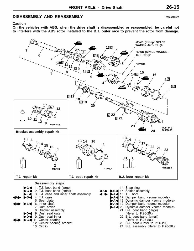
DISASSEMBLY AND REASSEMBLY 26100370325
CautionOn the vehicles with ABS, when the drive shaft is disassembled or reassembled, be careful notto interfere with the ABS rotor installed to the B.J. outer race to prevent the rotor from damage.
T.J. repair kit T.J. boot repair kit B.J. boot repair kit
3
4
67
7
16
2
13 414
13 14 16 1 213
19232122
1
2
11
14138
9
10
17
2
1
15
12
151
14
Bracket assembly repair kit
4
413
16
1718
1920
2122
2324
13
10 1112 9
<2WD (except SPACEWAGON-M/T-R.H.)>
<2WD (SPACE WAGON-M/T-R.H.)>
<4WD>
5
5
Disassembly steps"GA 1. T.J. boot band (large)"GA 2. T.J. boot band (small)"FA 3. T.J. case and inner shaft assembly
AA" "BA 4. T.J. case5. Seal plate
AB" "EA 6. Inner shaft7. Dust cover8. Bracket assembly
"DA 9. Dust seal outer"DA 10. Dust seal inner
AC" "CA 11. Center bearing12. Center bearing bracket13. Circlip
14. Snap ringAA" "BA 15. Spider assemblyAD" "AA 16. T.J. boot
"AA 17. Damper band <some models>"AA 18. Dynamic damper <some models>"AA 19. Damper band <some models>"AA 20. Dynamic damper <some models>
21. B.J. boot band (large)(Refer to P.26-20.)
22. B.J. boot band (small)(Refer to P.26-20.)
23. B.J. boot (Refer to P.26-20.)24. B.J. assembly (Refer to P.26-20.)

FRONT AXLE - Drive Shaft26-16
DISASSEMBLY SERVICE POINTSAA" T.J. CASE/SPIDER ASSEMBLY REMOVAL1. Wipe off grease from the spider assembly and the inside
of the T.J. case.2. Always clean the spider assembly when the grease
contains water or foreign material.
CautionDo not disassemble the spider assembly.
AB" INNER SHAFT REMOVAL1. Use the special tool to remove the inner shaft assembly,
together with the seal plate, from the T.J. case.
2. Use the special tools to remove the inner shaft from thebracket.
AC"CENTER BEARING REMOVAL
AD" T.J. BOOT REMOVAL1. Wipe off grease from the shaft spline.2. When reusing the T.J. boot, wrap plastic tape around
the shaft spline to avoid damaging the boot.
T.J. case Bar
Seal plate Bar
MB991248
MB991248
MB990197
MB990302
MB990938
MB990932

FRONT AXLE - Drive Shaft 26-17
REASSEMBLY SERVICE POINTS"AADYNAMIC DAMPER/DAMPER BAND/T.J. BOOT
INSTALLATION1. Install the dynamic damper in the position shown in the
illustration.
Items A (large) B (small)
SPACE RUNNER L.H. - 215 mm
R.H. 395 mm -
SPACE WAGON L.H. - 215 mm
R.H. 405 mm 585 mm
2. Secure the damper bands.
CautionThere should be no grease adhered to the rubberpart of the dynamic damper.
3. Wrap plastic tape around the shaft spline, and then installthe T.J. boot band (small) and T.J. boot.
"BASPIDER ASSEMBLY/T.J. CASE INSTALLATION1. Apply the specified grease furnished in the repair kit to
the spider assembly between the spider axle and theroller.
Specified grease: Repair kit grease
Caution(1) The drive shaft joint uses special grease. Do not
mix old and new or different types of grease.(2) If the spider assembly has been cleaned, take
special care to apply the specified grease.
2. Install the spider assembly to the shaft from the directionof the spline bevelled section.
3. After applying the specified grease to the T.J. case, insertthe drive shaft and apply grease one more time.
Specified grease: Repair kit grease
Amount to use:<SPACE RUNNER> 110 g<SPACE WAGON - 2WD> 140 g<SPACE WAGON - 4WD> 105 g
NOTEThe grease in the repair kit should be divided in halffor use, respectively, at the joint and inside the boot.
CautionThe drive shaft joint uses special grease. Do not mixold and new or different types of grease.
B
A
Bevelledsection

FRONT AXLE - Drive Shaft26-18
"CACENTER BEARING INSTALLATION
"DADUST SEAL INNER/DUST SEAL OUTERINSTALLATION
1. Apply multi-purpose grease to the rear surfaces of alldust seals.
Amount to use:Dust seal inner 14 - 20 gDust seal outer 8 - 12 g
2. Use the special tools to install the dust seal so that itssurface runs even with that of the center bearing bracket.
3. Apply multi-purpose grease to the lip of each dust seal.
NOTEWhen applying grease, make sure that it does not adhereto anything outside the lip.
"EA INNER SHAFT INSTALLATION
"FA T.J. CASE AND INNER SHAFT ASSEMBLYINSTALLATION
1. Apply multi-purpose grease to the inner shaft spline, thenpress fit into the T.J. case.
MB990938
MB990933
Bearing
MB990938
MB990933
INNER DUST SEAL
OUTER DUST SEAL
MB990938MB990931
Inner shaft
MB991172
Inner shaftassembly
T.J. case

FRONT AXLE - Drive Shaft 26-19
2. Use the special tools to support the T.J. case.3. Use a pipe [Ø 30 mm] to press the seal plate into the
T.J. case.
"CA T.J. BOOT BAND (SMALL)/T.J. BOOT BAND(LARGE) INSTALLATION
Set the T.J. boot bands at the specified distance in orderto adjust the amount of air inside the T.J. boot, and thentighten the T.J. boot bands securely.
Standard value (A):<SPACE RUNNER> 82 mm<SPACE WAGON - 2WD> 81 mm<SPACE WAGON - 4WD> 90 mm
INSPECTION 26100380083
D Check the drive shaft for damage, bending or corrosion.D Check the inner shaft for damage, bending or corrosion.D Check the drive shaft spline part for wear or damage.D Check the inner shaft spline part for wear or damage.D Check the spider assembly for roller rotation, wear or
corrosion.D Check the groove inside T.J. case for wear or corrosion.D Check the dynamic damper for damage or cracking.D Check the boots for deterioration, damage or cracking.D Check the center bearing for seizure, discoloration or
roughness of rolling surface.D Check the dust cover for damage or deterioration.
PipeT.J. case
Seal plate
MB991248
A

FRONT AXLE - Drive Shaft26-20
B.J. BOOT (RESIN BOOT) REPLACEMENT26100520157
1. Remove the B.J. boot bands (large and small).
NOTEThe B.J. boot bands cannot be re-used.
2. Remove the B.J. boot.3. Wrap a plastic tape around the shaft spline, and assemble
the B.J. boot band and B.J. boot.
4. Install the B.J. boot with the part with the smallest diameterin a position such that the shaft groove can be seen.<2WD>
5. Engage the small diameter side of the plastic boot intothe shaft groove <4WD>.
6. Turn the adjusting bolt on the special tool so that thesize of the opening (W) is at the standard value.
Standard value (W): 2.9 mm<If it is larger than 2.9 mm>
Tighten the adjusting bolt.<If it is smaller than 2.9 mm>
Loosen the adjusting bolt.
NOTE(1) The value of W will change by approximately 0.7
mm for each turn of the adjusting bolt.(2) The adjusting bolt should not be turned more than
once.
Groove
MB991561
Stopper
Adjusting bolt
W

FRONT AXLE - Drive Shaft 26-21
7. Place the B.J. boot band (small) against the projection atthe edge of the boot, and then secure it so that there is aclearance left as shown by (A) in the illustration.
8. Use the special tool to crimp the B.J. boot band (small).
Caution(1) Secure the drive shaft in an upright position and
clamp the part of the B.J. boot band to be crimpedsecurely in the jaws of the special tool.
(2) Crimp the B.J. boot band until the special tooltouches the stopper.
9. Check that the crimping amount (B) of the B.J. boot bandis at the standard value.
Standard value (B): 2.4 - 2.8 mm<If the crimping amount is larger than 2.8 mm>
Readjust the value of (W) in step 6 accordingto the following formula, and then repeat theoperation in step 8.W = 5.5 mm - BExample: If B = 2.9 mm, then W = 2.6 mm.
<If the crimping amount is smaller than 2.4 mm>Remove the B.J. boot band, readjust the valueof (W) in step 6 according to the followingformula, and then repeat the operations insteps 7 and 8 using a new B.J. boot band.W = 5.5 mm - BExample: If B = 2.3 mm, then W = 3.2 mm.
10. Check that the B.J. boot band is not sticking out pastthe place where it has been installed.If the B.J. boot band is sticking out, remove it and thenrepeat the operations in steps 7 to 9 using a new B.J.boot band.
11. Fill the inside of the B.J. boot with the specified amountof the specified grease.
Specified grease: Repair kit grease
Amount to use: <2WD> 125 g, <4WD> 95 g
CautionThe drive shaft joint uses special grease. Do not mixold and new or different types of grease.
B.J. boot
B.J. boot band(small)
Projection
A
MB991561
B

FRONT AXLE - Drive Shaft26-22
12. Engage the large diameter side of the B.J. boot into theB.J. housing groove. <2WD>
13. Install the B.J. boot band (large) so that there is theclearance (C) between it and the B.J. housing is at thestandard value. <4WD>
Standard value (C): 0.1 - 1.5 mm
14. Follow the same procedure as in step 6 to adjust thesize of the opening (W) on the special tool so that itis at the standard value.
Standard value (W): 3.2 mm
15. Place the B.J. boot band (large) against the projectionat the edge of the boot, and then secure it so that thereis a clearance left as shown by (D) in the illustration.
16. Use the special tool to crimp the B.J. boot band (large)in the same way as in step 8.
17. Check that the crimping amount (E) of the B.J. boot bandis at the standard value.
Standard value (e): 2.4 - 2.8 mm<If the crimping amount is larger than 2.8 mm>
Readjust the value of (W) in step 13 accordingto the following formula, and then repeat theoperation in step 15.W = 5.8 mm - EExample: If E = 2.9 mm, then W = 2.9 mm.
<If the crimping amount is smaller than 2.4 mm>Remove the B.J. boot band, readjust the valueof (W) in step 13 according to the followingformula, and then repeat the operations insteps 14 and 15 using a new B.J. boot band.W = 5.8 mm - EExample: If E = 2.3 mm, then W = 3.5 mm.
18. Check that the B.J. boot band is not sticking out pastthe place where it has been installed.If the B.J. boot band is sticking out, remove it and thenrepeat the operations in steps 14 to 16 using a newB.J. boot band.
Groove
C
B.J. bootProjection
B.J. boot band(large)
D
E