
26076
144
Installation (Set Builder) Manual EGCP-2 Engine Generator Control Package 8406-115, 150–300 Vac PT Input, 9–32 Vdc 8406-116, 50–150 Vac PT Input, 9–32 Vdc Manual 26076 (Revision F)
-
Upload
gabiacu123 -
Category
Documents
-
view
30 -
download
4
Transcript of 26076
Installation (Set Builder) Manual
EGCP-2 Engine Generator Control Package
8406-115, 150–300 Vac PT Input, 9–32 Vdc 8406-116, 50–150 Vac PT Input, 9–32 Vdc
Manual 26076 (Revision F)
WARNING—DANGER OF DEATH OR PERSONAL INJURY
WARNING—FOLLOW INSTRUCTIONS Read this entire manual and all other publications pertaining to the work to be performed before installing, operating, or servicing this equipment. Practice all plant and safety instructions and precautions. Failure to follow instructions can cause personal injury and/or property damage.
WARNING—OUT-OF-DATE PUBLICATION This publication may have been revised or updated since this copy was produced. To verify that you have the latest revision, be sure to check the Woodward website:
www.woodward.com/pubs/current.pdf The revision level is shown at the bottom of the front cover after the publication number. The latest version of most publications is available at:
www.woodward.com/publications If your publication is not there, please contact your customer service representative to get the latest copy.
WARNING—OVERSPEED PROTECTION The engine, turbine, or other type of prime mover should be equipped with an overspeed shutdown device to protect against runaway or damage to the prime mover with possible personal injury, loss of life, or property damage. The overspeed shutdown device must be totally independent of the prime mover control system. An overtemperature or overpressure shutdown device may also be needed for safety, as appropriate.
WARNING—PROPER USE Any unauthorized modifications to or use of this equipment outside its specified mechanical, electrical, or other operating limits may cause personal injury and/or property damage, including damage to the equipment. Any such unauthorized modifications: (i) constitute "misuse" and/or "negligence" within the meaning of the product warranty thereby excluding warranty coverage for any resulting damage, and (ii) invalidate product certifications or listings.
CAUTION—POSSIBLE DAMAGE TO EQUIPMENT OR PROPERTY
CAUTION—BATTERY CHARGING To prevent damage to a control system that uses an alternator or battery-charging device, make sure the charging device is turned off before disconnecting the battery from the system.
CAUTION—ELECTROSTATIC DISCHARGE Electronic controls contain static-sensitive parts. Observe the following precautions to prevent damage to these parts. • Discharge body static before handling the control (with power to the control turned off,
contact a grounded surface and maintain contact while handling the control). • Avoid all plastic, vinyl, and Styrofoam (except antistatic versions) around printed circuit
boards. • Do not touch the components or conductors on a printed circuit board with your hands
or with conductive devices.
IMPORTANT DEFINITIONS • A WARNING indicates a potentially hazardous situation which, if not avoided, could result in
death or serious injury. • A CAUTION indicates a potentially hazardous situation which, if not avoided, could result in
damage to equipment or property. • A NOTE provides other helpful information that does not fall under the warning or caution
categories. Revisions—Text changes are indicated by a black line alongside the text. Woodward Governor Company reserves the right to update any portion of this publication at any time. Information provided by Woodward Governor Company is believed to be correct and reliable. However, no responsibility is assumed by Woodward Governor Company unless otherwise expressly undertaken.
© Woodward 2000 All Rights Reserved
Manual 26076 EGCP-2 Engine Generator Control Package
Woodward i
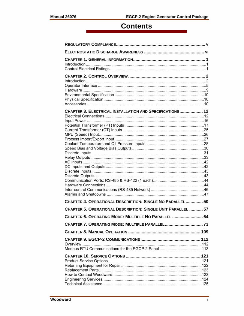
Contents
REGULATORY COMPLIANCE......................................................................... V ELECTROSTATIC DISCHARGE AWARENESS ................................................. VI CHAPTER 1. GENERAL INFORMATION........................................................... 1 Introduction.............................................................................................................1 Control Electrical Ratings .......................................................................................1 CHAPTER 2. CONTROL OVERVIEW ............................................................... 2 Introduction.............................................................................................................2 Operator Interface ..................................................................................................5 Hardware ................................................................................................................9 Environmental Specification .................................................................................10 Physical Specification...........................................................................................10 Accessories ..........................................................................................................10 CHAPTER 3. ELECTRICAL INSTALLATION AND SPECIFICATIONS................... 12 Electrical Connections..........................................................................................12 Input Power ..........................................................................................................16 Potential Transformer (PT) Inputs ........................................................................17 Current Transformer (CT) Inputs..........................................................................25 MPU (Speed) Input...............................................................................................26 Process Import/Export Input.................................................................................27 Coolant Temperature and Oil Pressure Inputs.....................................................28 Speed Bias and Voltage Bias Outputs .................................................................30 Discrete Inputs......................................................................................................31 Relay Outputs.......................................................................................................33 AC Inputs..............................................................................................................42 DC Inputs and Outputs.........................................................................................42 Discrete Inputs......................................................................................................43 Discrete Outputs...................................................................................................43 Communication Ports: RS-485 & RS-422 (1 each)..............................................44 Hardware Connections.........................................................................................44 Inter-control Communications (RS-485 Network) ................................................46 Alarms and Shutdowns ........................................................................................47 CHAPTER 4. OPERATIONAL DESCRIPTION: SINGLE NO PARALLEL .............. 50 CHAPTER 5. OPERATIONAL DESCRIPTION: SINGLE UNIT PARALLEL ........... 57 CHAPTER 6. OPERATING MODE: MULTIPLE NO PARALLEL ......................... 64 CHAPTER 7. OPERATING MODE: MULTIPLE PARALLEL............................... 73 CHAPTER 8. MANUAL OPERATION ........................................................... 109 CHAPTER 9. EGCP-2 COMMUNICATIONS................................................. 112 Overview.............................................................................................................112 Modbus RTU Communications for the EGCP-2 Panel ......................................113 CHAPTER 10. SERVICE OPTIONS ............................................................. 121 Product Service Options.....................................................................................121 Returning Equipment for Repair.........................................................................122 Replacement Parts .............................................................................................123 How to Contact Woodward.................................................................................123 Engineering Services .........................................................................................124 Technical Assistance..........................................................................................125

EGCP-2 Engine Generator Control Package Manual 26076
ii Woodward
Contents
APPENDIX A. CONNECTOR INFORMATION .................................................126 APPENDIX B. SPEED BIAS CONNECTIONS.................................................128 DECLARATIONS .......................................................................................134 EGCP-2 CONTROL SPECIFICATIONS........................................................135
Illustrations and Tables Figure 2-1. EGCP-2 Interface Connections ...........................................................4 Figure 2-2. Operator Interface................................................................................5 Figure 2-3. Physical Outline with Dimensions of EGCP-2 ...................................11 Figure 3-1. CageClamp Termination Blocks (example photos) ...........................12 Figure 3-2. Recommended Single Point Grounding Scheme ..............................13 Figure 3-3. Wiring Diagram for EGCP-2...............................................................15 Figure 3-4. Dip Switch Location ...........................................................................16 Figure 3-5. Three Wire Delta PT Connection for EGCP-2 ...................................17 Figure 3-6. Four Wire WYE PT Connection .........................................................18 Figure 3-7. Utility / Local Bus PT Wiring for Delta and Wye Configuration ..........19 Figure 3-8a. Utility/Local Bus Single PT Wiring for Delta and WYE Configuration
(two relay) ........................................................................................20 Figure 3-8b. Utility/Local Bus Single PT Wiring for Delta and WYE Configuration
(single relay) ....................................................................................20 Figure 3-9a. PT Wiring Relationships for Generator, Bus, and Utility Inputs.......21 Figure 3-9b. PT Wiring Relationships for Generator, Bus, and Utility Inputs.......22 Figure 3-10a. PT Wiring Relationships for Generator, Bus, and Utility Inputs.....23 Figure 3-10b. PT Wiring Relationships for Generator, Bus, and Utility Inputs.....24 Figure 3-11. Current Transfer Wiring Diagram for EGCP-2.................................25 Figure 3-12. Wiring Diagram for MPU Input .........................................................26 Figure 3-13a. Wiring Diagram for Process Import/Export Input ...........................27 Figure 3-13b. Connecting a KW Transducer Signal to Multiple EGCP-2s...........27 Figure 3-14a. Wiring Diagram for Pressure Inputs...............................................28 Figure 3-14b. Wiring Diagram for Temperature Inputs ........................................29 Figure 3-15. Wiring Diagram for Speed Bias and Voltage Bias Outputs .............31 Figure 3-16. Wiring Diagram for Typical Discrete I/O Connections .....................33 Figure 3-17. Example of the Mains Breaker NO Output Connected to Close the
Mains (Utility) Breaker (ENERGIZE TO CLOSE) ............................34 Figure 3-18. Example Using the NC Output to Control the Mains (Utility)
Contactor (ENERGIZE TO OPEN) ..................................................35 Figure 3-19. Example of the Generator Breaker Close NO Output Connected to
Close the Generator Breaker (ENERGIZE TO CLOSE) .................36 Figure 3-20. Example Using the NO Contacts to Control the Generator’s
Contactor (ENERGIZE TO CLOSE) ................................................36 Figure 3-21. Example Using the NO Contacts to Control the Mains Breaker Trip
(Open) Coil (ENERGIZE TO OPEN) ...............................................39 Figure 3-22. Example Using the NC Contacts to Control the Generator Breakers
Open Coil (DE-ENERGIZE TO OPEN) ...........................................40
Manual 26076 EGCP-2 Engine Generator Control Package
Woodward iii
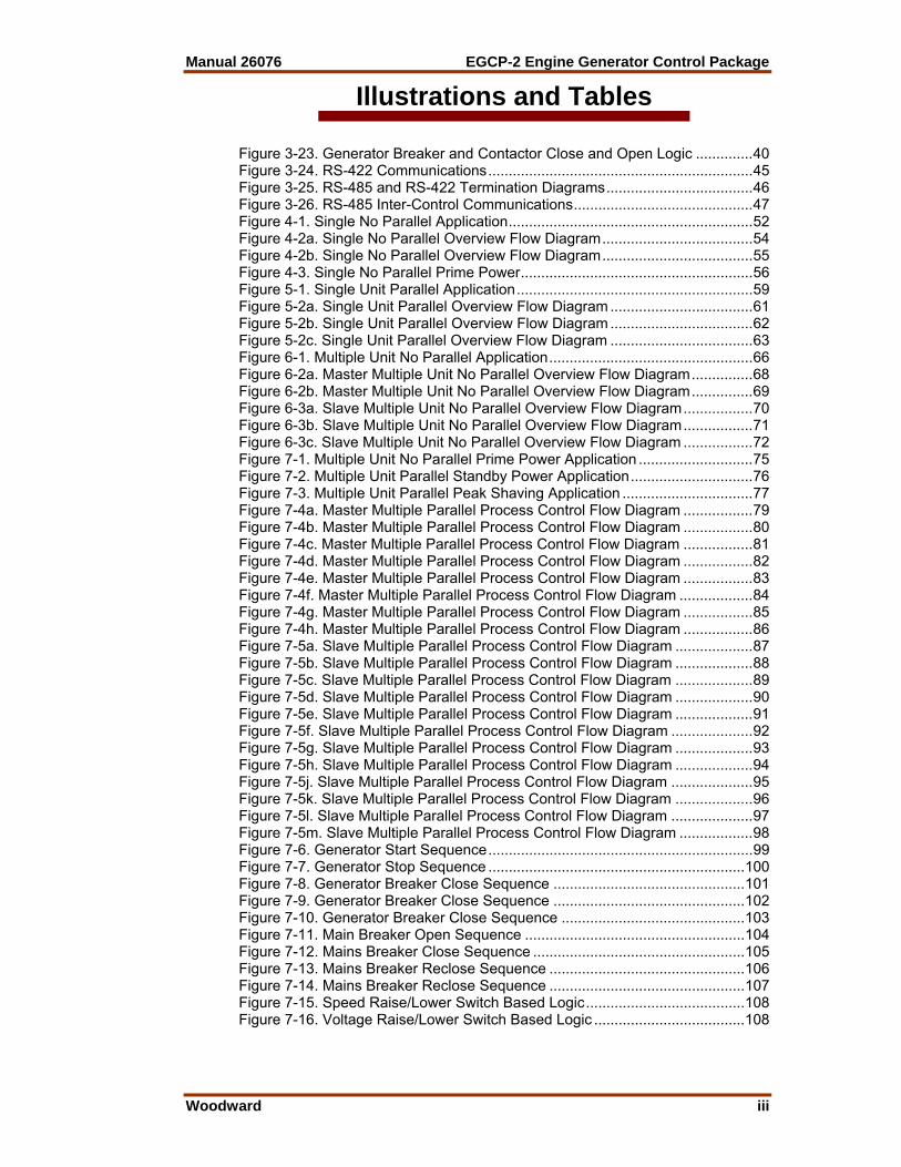
Illustrations and Tables Figure 3-23. Generator Breaker and Contactor Close and Open Logic ..............40 Figure 3-24. RS-422 Communications.................................................................45 Figure 3-25. RS-485 and RS-422 Termination Diagrams....................................46 Figure 3-26. RS-485 Inter-Control Communications............................................47 Figure 4-1. Single No Parallel Application............................................................52 Figure 4-2a. Single No Parallel Overview Flow Diagram.....................................54 Figure 4-2b. Single No Parallel Overview Flow Diagram.....................................55 Figure 4-3. Single No Parallel Prime Power.........................................................56 Figure 5-1. Single Unit Parallel Application..........................................................59 Figure 5-2a. Single Unit Parallel Overview Flow Diagram ...................................61 Figure 5-2b. Single Unit Parallel Overview Flow Diagram ...................................62 Figure 5-2c. Single Unit Parallel Overview Flow Diagram ...................................63 Figure 6-1. Multiple Unit No Parallel Application..................................................66 Figure 6-2a. Master Multiple Unit No Parallel Overview Flow Diagram...............68 Figure 6-2b. Master Multiple Unit No Parallel Overview Flow Diagram...............69 Figure 6-3a. Slave Multiple Unit No Parallel Overview Flow Diagram.................70 Figure 6-3b. Slave Multiple Unit No Parallel Overview Flow Diagram.................71 Figure 6-3c. Slave Multiple Unit No Parallel Overview Flow Diagram .................72 Figure 7-1. Multiple Unit No Parallel Prime Power Application ............................75 Figure 7-2. Multiple Unit Parallel Standby Power Application..............................76 Figure 7-3. Multiple Unit Parallel Peak Shaving Application ................................77 Figure 7-4a. Master Multiple Parallel Process Control Flow Diagram .................79 Figure 7-4b. Master Multiple Parallel Process Control Flow Diagram .................80 Figure 7-4c. Master Multiple Parallel Process Control Flow Diagram .................81 Figure 7-4d. Master Multiple Parallel Process Control Flow Diagram .................82 Figure 7-4e. Master Multiple Parallel Process Control Flow Diagram .................83 Figure 7-4f. Master Multiple Parallel Process Control Flow Diagram ..................84 Figure 7-4g. Master Multiple Parallel Process Control Flow Diagram .................85 Figure 7-4h. Master Multiple Parallel Process Control Flow Diagram .................86 Figure 7-5a. Slave Multiple Parallel Process Control Flow Diagram ...................87 Figure 7-5b. Slave Multiple Parallel Process Control Flow Diagram ...................88 Figure 7-5c. Slave Multiple Parallel Process Control Flow Diagram ...................89 Figure 7-5d. Slave Multiple Parallel Process Control Flow Diagram ...................90 Figure 7-5e. Slave Multiple Parallel Process Control Flow Diagram ...................91 Figure 7-5f. Slave Multiple Parallel Process Control Flow Diagram ....................92 Figure 7-5g. Slave Multiple Parallel Process Control Flow Diagram ...................93 Figure 7-5h. Slave Multiple Parallel Process Control Flow Diagram ...................94 Figure 7-5j. Slave Multiple Parallel Process Control Flow Diagram ....................95 Figure 7-5k. Slave Multiple Parallel Process Control Flow Diagram ...................96 Figure 7-5l. Slave Multiple Parallel Process Control Flow Diagram ....................97 Figure 7-5m. Slave Multiple Parallel Process Control Flow Diagram ..................98 Figure 7-6. Generator Start Sequence.................................................................99 Figure 7-7. Generator Stop Sequence ...............................................................100 Figure 7-8. Generator Breaker Close Sequence ...............................................101 Figure 7-9. Generator Breaker Close Sequence ...............................................102 Figure 7-10. Generator Breaker Close Sequence .............................................103 Figure 7-11. Main Breaker Open Sequence ......................................................104 Figure 7-12. Mains Breaker Close Sequence ....................................................105 Figure 7-13. Mains Breaker Reclose Sequence ................................................106 Figure 7-14. Mains Breaker Reclose Sequence ................................................107 Figure 7-15. Speed Raise/Lower Switch Based Logic.......................................108 Figure 7-16. Voltage Raise/Lower Switch Based Logic .....................................108
EGCP-2 Engine Generator Control Package Manual 26076
iv Woodward
Illustrations and Tables Table 9-1. Examples of Modbus Control Mode Switching Logic....................... 114 Table 9-2. Modbus Addresses for the RTU Protocol ........................................ 117 Table 9-3. Common Modbus Error Numbers .................................................... 120 Table 9-4. Typical Modbus Communications Settings ...................................... 120
WARNING—EARTH GROUND Protective Earth (PE) must be connected to the termination point on the back side of the unit next to the label with the symbol (or 1 of 3 other similar termination points without label) to reduce the risk of electric shock. This connection will be made using a thread-forming screw. The conductor providing the connection must have a properly sized ring lug and wire larger than or equal to 3.0 mm² (12 AWG).
WARNING—TRAINED PERSONNEL/HIGH VOLTAGE The calibration and checkout procedure should only be performed by authorized personnel knowledgeable of the risks posed by live electrical equipment.

Manual 26076 EGCP-2 Engine Generator Control Package
Woodward v
Regulatory Compliance European Compliance for CE Mark: EMC Directive Declared to 89/336/EEC COUNCIL
DIRECTIVE of 03 May 1989 on the approximation of the laws of the member states relating to electromagnetic compatibility.
Low Voltage Directive Declared to the 73/23/EEC COUNCIL DIRECTIVE of 19 February 1973 on the harmonization of the laws of the Member States relating to electrical equipment designed for use within certain voltage limits.
North American Compliance: UL UL Listed for Ordinary Locations at 70 °C
maximum Ambient. For use in the United States and Canada.
UL File E97763 CSA CSA Certified for Ordinary Locations at 70
°C maximum Ambient. For use in the United States and Canada.
Certificate 1159277 NOTE Wiring must be in accordance with
applicable electric codes with the authority having jurisdiction.
General Installation and Operation Notes and Warnings • The EGCP-2 is suitable for use in non-hazardous locations only. • Wiring must be in accordance with applicable electrical codes and in
accordance with the authority having jurisdiction. • Field wiring must be suitable for at least 90 °C. • Connect ground terminal to PE (Protective Earth). • More than one live circuit (see wiring diagram).

EGCP-2 Engine Generator Control Package Manual 26076
vi Woodward
Electrostatic Discharge Awareness All electronic equipment is static-sensitive, some components more than others. To protect these components from static damage, you must take special precautions to minimize or eliminate electrostatic discharges. Follow these precautions when working with or near the control. 1. Before doing maintenance on the electronic control, discharge the static
electricity on your body to ground by touching and holding a grounded metal object (pipes, cabinets, equipment, etc.).
2. Avoid the build-up of static electricity on your body by not wearing clothing
made of synthetic materials. Wear cotton or cotton-blend materials as much as possible because these do not store static electric charges as much as synthetics.
3. Keep plastic, vinyl, and Styrofoam materials (such as plastic or Styrofoam
cups, cup holders, cigarette packages, cellophane wrappers, vinyl books or folders, plastic bottles, and plastic ash trays) away from the control, the modules, and the work area as much as possible.
4. Do not remove the printed circuit board (PCB) from the control cabinet
unless absolutely necessary. If you must remove the PCB from the control cabinet, follow these precautions:
• Do not touch any part of the PCB except the edges. • Do not touch the electrical conductors, the connectors, or the
components with conductive devices or with your hands. • When replacing a PCB, keep the new PCB in the plastic antistatic
protective bag it comes in until you are ready to install it. Immediately after removing the old PCB from the control cabinet, place it in the antistatic protective bag.
CAUTION—ELECTROSTATIC DISCHARGE To prevent damage to electronic components caused by improper handling, read and observe the precautions in Woodward manual 82715, Guide for Handling and Protection of Electronic Controls, Printed Circuit Boards, and Modules.
Manual 26076 EGCP-2 Engine Generator Control Package
Woodward 1
Chapter 1. General Information
Introduction This manual describes the Woodward EGCP-2 Engine Generator Control Package, models 8406-115 and 8406-116 (9–32 Vdc maximum input voltage range).
Control Electrical Ratings nominal supply voltage range 10–29 Vdc (12 or 14 volt systems) max. power consumption at rated voltage 20 W max. PT input voltage range 150–300 Vac rms (8406-115) 50–150 Vac rms (8406-116) max. CT current input range 0–6 A rms max. generator frequency range 40–70 Hz

EGCP-2 Engine Generator Control Package Manual 26076
2 Woodward
Chapter 2. Control Overview
Introduction The EGCP-2 is a microprocessor based complete generator load control and engine management package. It is designed for use with an automatic voltage regulator and Woodward speed control to automate and protect diesel or gas engine based backup generator sets. Designed for small to medium size generator sets the EGCP-2 can be configured to operate stand-alone or utility paralleled sets. A network of EGCP-2 controls is capable of controlling up to eight un-manned generator sets for backup power, base-load, or peak shaving applications. Engine Control • Engine Pre-glow • Fuel Solenoid Control • Engine Starter Control (Cranking) • KVA Controlled Cool-down Timer • Oil Pressure Monitoring • Water Temperature Monitoring • Battery Voltage Monitoring • Speed Monitoring with Overspeed Protection • Idle /Rated Relay Synchronizing • Digital signal processing to eliminate problems induced in systems with high
harmonic content causing multiple zero crossing of voltage waveforms. • Adjustable maximum phase window, voltage window, and dwell times—
windows as small as 2° phase error and 0.1% voltage matching respectively.
• Safe dead bus closing logic internal to the control. • Multiple shot re-closing with adjustable time delays, auto-resynchronizing,
and synchronizer time-outs all available. • Manual voltage and speed adjusts for manual synchronizing (Sync-Check
still active during manual parallels). • Synchronization across generator and mains breakers. Real (kW) Load Control • True RMS power calculations for rapid, accurate load control even in the
presence of harmonics. • Smooth user chosen ramp rates into and out of each mode of operation. • Isochronous load-sharing of up to 8 units based on percentage loading
(allows different rated machines to proportionally balance kW loads). • Constant base loading for optimum fuel efficiency with discrete inputs to
change load levels remotely. • Import/Export control with an external watt transducer. • Soft Utility Transfer Function
Manual 26076 EGCP-2 Engine Generator Control Package
Woodward 3
• Externally adjustable Base Load or Process Reference Levels with independent ramp rates
• kW droop provided for manual load control. Reactive (KVAR) Control • VAR sharing on isolated busses based on percentage reactive load (allows
different rated machines to proportionally balance KVAR loads). • Constant Power factor or VAR base loading on units which are in kW base
load control mode, or process control mode. • Externally adjustable VAR or PF control reference levels. Automatic Generator Sequencing • Automatically starts additional EGCP-2 equipped generators when load
exceeds a user specified percentage of the rated load of the operating machines.
• Provides controlled unloads for engines when the load is low enough that the remaining engines will not exceed a user specified percentage of the rated load.
• Engine priority sequence can be changed from any unit or from a PC to equalize run-time.
Generator Protective Features • Over/Under Voltage • Over/Under Frequency • Reverse Power (Inverse time delay) • Loss of Excitation • Overcurrent (Inverse time delay) • Loss of mains (utility) detection • Speed/Frequency Mismatch • Load Surge • KVA Load Switch Engine Protective Features • High/Low Coolant Temperature • High/Low Oil Pressure • Overspeed • Start Failure Communication – PC Interface • Easy upload and download and backup of unit configuration • A PC can control or monitor any unit at a site by a single connection to the
local operating network via RS-422 serial port using Modbus® * or ServLink protocol.
* Modbus is a registered trademark of Modicon, Inc.
EGCP-2 Engine Generator Control Package Manual 26076
4 Woodward
Util
ity/B
us In
put
Test EngineG
ener
ator
Bre
aker
TO O
the r
Gen
erat
ors
Plant Load
GEN
Gen
Bre
aker
Engine Preglow
Oil
Pr e
ssur
eW
ater
Tem
pera
ture
Loca
l Bus
Dis
conn
ect
GB
Aux
In
Util
ityB
reak
erUTI
LIT Y
Wat
tTr
ansd
uce r
Util
ity T
B O
pen/
Clo
se
Mai
ns P
T
Pro
cess
Inpu
t
Util
ity T
B A
u x
Automatic
LAM
P
EG
CP G
en P
T In
puts
(3 p
hase
s)G
e n C
T in
puts
(3 p
hase
s )V
olta
ge B
ias
ALA
RM
(VIS
UAL
)
AL A
RM
(AU
DIB
LE)
Vol
tage
Reg
u lat
orS
peed
Con
tr ol
Spe
ed B
ias
Engine Crank
Fuel Shutoff Solenoid
MP
U
HO
RN
RS
-485
Po r
t
PC
Inte
rface
RS
-422
Voltage Lower
Voltage Raise
Run With Load
Speed Lower
Speed Raise
Fault 2
Fault 1
Process I/E
PC
TO O
ther
EG
CP
s
Ope
rato
r Co n
trol P
anel
Ope
n/C
lose
EGC
P-2
Inte
rfa c
es
Dis
conn
ect
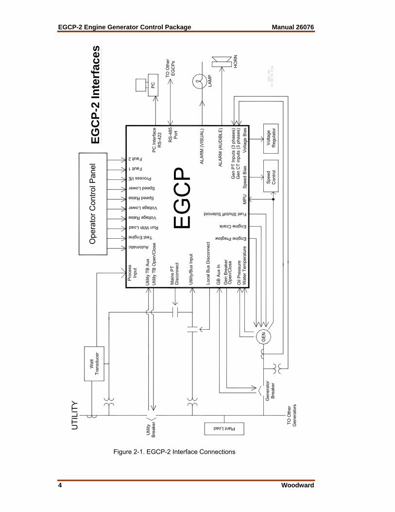
Figure 2-1. EGCP-2 Interface Connections

Manual 26076 EGCP-2 Engine Generator Control Package
Woodward 5
Operator Interface The EGCP-2 Operator Interface is designed for simplicity and redundancy of function in all operating modes. Two backlit Liquid Crystal Display screens with contrast adjustment are used to display various operating and status information to the operator, as well as for tuning set points. The backlight on the LCD screens will stay on whenever the engine speed is above 50 rpm. When the engine is not running, the backlight will turn on whenever any key is pressed on the front panel. The backlight will turn off after 5 minutes of non-use, when the engine is not running. Additionally, in the event of a drop in supply voltage where the monitored battery voltage drops below 9.0 Vdc, the LCD back light will shut off to conserve power.
NOTE The EGCP-2 Operator Interface can only be used for unit configuration and monitoring. Unit start/stop, sync, or mode selection commands cannot be given through the EGCP-2’s front panel.
WARNING—TRAINED PERSONNEL An unsafe condition could occur with improper use of these software tools. Only trained personnel should have access to these tools. The unit’s front panel screens provide eight lines of Status Information, with the option of displaying four lines of configuration or Alarm Log information. These screens allow the user to monitor and tune related parameters at the same time.
Figure 2-2. Operator Interface A red Light Emitting Diode (LED) on the face of the control is used to indicate an alarm condition by flashing repeatedly, and to indicate a shutdown condition by staying on continuously.
EGCP-2 Engine Generator Control Package Manual 26076
6 Woodward
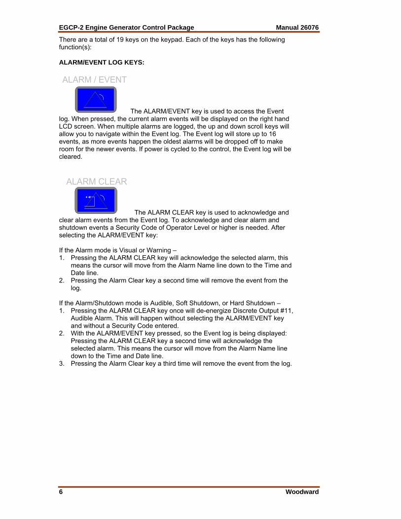
There are a total of 19 keys on the keypad. Each of the keys has the following function(s): ALARM/EVENT LOG KEYS: ALARM / EVENT
The ALARM/EVENT key is used to access the Event log. When pressed, the current alarm events will be displayed on the right hand LCD screen. When multiple alarms are logged, the up and down scroll keys will allow you to navigate within the Event log. The Event log will store up to 16 events, as more events happen the oldest alarms will be dropped off to make room for the newer events. If power is cycled to the control, the Event log will be cleared.
ALARM CLEAR
The ALARM CLEAR key is used to acknowledge and clear alarm events from the Event log. To acknowledge and clear alarm and shutdown events a Security Code of Operator Level or higher is needed. After selecting the ALARM/EVENT key: If the Alarm mode is Visual or Warning – 1. Pressing the ALARM CLEAR key will acknowledge the selected alarm, this
means the cursor will move from the Alarm Name line down to the Time and Date line.
2. Pressing the Alarm Clear key a second time will remove the event from the log.
If the Alarm/Shutdown mode is Audible, Soft Shutdown, or Hard Shutdown – 1. Pressing the ALARM CLEAR key once will de-energize Discrete Output #11,
Audible Alarm. This will happen without selecting the ALARM/EVENT key and without a Security Code entered.
2. With the ALARM/EVENT key pressed, so the Event log is being displayed: Pressing the ALARM CLEAR key a second time will acknowledge the selected alarm. This means the cursor will move from the Alarm Name line down to the Time and Date line.
3. Pressing the Alarm Clear key a third time will remove the event from the log.

Manual 26076 EGCP-2 Engine Generator Control Package
Woodward 7
NAVIGATION and ADJUSTMENT KEYS:
SCROLL
The SCROLL KEY is used to move the cursor up, down , left and right. It also is used to increment and decrement values while in the configuration menus.
ESC
The ESCAPE KEY is used to move upwards (out of )the configuration menu levels. It also is used when tuning a value to restore the previous value, if the new value is not entered into memory (see the enter key, below).
ENTER
The ENTER KEY is used to move downwards (into) the configuration menu levels. It is also used to when tuning a value to enter the new value to memory. It also serves as a means to commit alarm event items to the alarm event list without removing them. This is known as logging the alarm event item. Pressing the enter key while on the selected alarm/event item will “save” that item to the event list. If the selected alarm event was an active alarm event, the action(s) associated with the alarm event will also be cleared from the control logic. STATUS and CONFIGURATION KEYS:
iSTATUS
The STATUS KEY, when pressed, will put both left and right LCDs into the status display mode. The status displays provide information about different items of engine and generator set operation. See the STATUS MENU buttons, below for details on the various status keys. There are no adjustment values in the status menus.

EGCP-2 Engine Generator Control Package Manual 26076
8 Woodward
CONFIG
...The CONFIG KEY, when pressed, will put the right hand LCD
into the configuration mode. Configuration menu items will be displayed in the right hand screen. Status information will continue to be displayed in the left hand screen. Since there are various menu items and adjustments in the configuration menu, a blinking cursor is provided in the right hand display when the configure mode is active. STATUS MENU KEYS: The contents of the various status menus are described in the Status Screens section in Chapter 3 of this manual.
SYSTEM
The SYSTEM STATUS key, when pressed displays the system status information. The system status display is also the default status display screen (it is always the first display shown after a power up of the control). This display shows general information about the operation of the engine generator set.
ENGINE
The ENGINE STATUS key , when pressed displays status information about the engine functions and operation.
GEN
The GEN STATUS key shows three phase generator parameters when pressed.
I/O
The I/O STATUS key provides the status of all the discrete inputs and outputs, as well as information on analog inputs and outputs.

Manual 26076 EGCP-2 Engine Generator Control Package
Woodward 9
SYNC
The SYNC STATUS key shows status information regarding the generator breaker and utility breaker synchronizer.
KW LOAD
The KW LOAD STATUS key, when pressed, shows the status information for the KW load control of the EGCP-2.
PF / KVAR
Press the PF/KVAR STATUS key to display VAR/PF Mode information, as well as three phase generator voltage and current.
SEQUENCE
The SEQUENCE STATUS key provides sequencing information for multiple unit systems. Single unit systems, and units not in the AUTO mode will not provide status information in this screen.
ATS
The ATS STATUS key, when pressed, displays the status information for the Automatic Transfer Switch functions.
Hardware The EGCP-2 is an integrated control package. All control hardware is contained in one compact enclosure. Figure 2-3 is a physical outline drawing with dimensions of the EGCP-2 for reference during the construction of mounting panels, etc. To mount the EGCP-2 panel use type M5 x 12mm thread forming screws (Woodward part number 1029-529).
NOTE When mounting into an enclosure, make sure the enclosure is vented to atmosphere through a Type 4 vent tube or unsealed conduit.

EGCP-2 Engine Generator Control Package Manual 26076
10 Woodward
Environmental Specification Temperature Range around outside of EGCP-2 Chassis –20 to +70 °C operating Relative Humidity 95% non-condensing, at 20 to 55 °C
Physical Specification Enclosure Size 282 x 358 x 69 mm 11.1 x 14.1 x 2.7 inch
Accessories Other components you may need. These items do not ship with the 8406-115 or 8406-116 part numbers—they must be ordered separately. • 8928-301—EGCP-2 connector kit. Contains all of the mating terminal blocks
for the EGCP-2. See Appendix A for mating connector information. • 5417-551—Communication Cable for RS422. This cable will connect your
PC to the EGCP-2 RS422 port. This is a point-to-point connection. It can be used with EGCP-2 software tools.
• Download.exe—see manual 26086, Appendix B. • EGCP-2 HMI—see manual 26099.

Manual 26076 EGCP-2 Engine Generator Control Package
Woodward 11
Figure 2-3. Physical Outline with Dimensions of EGCP-2

EGCP-2 Engine Generator Control Package Manual 26076
12 Woodward
Chapter 3. Electrical Installation and Specifications
Electrical Connections All inputs and outputs to the EGCP-2 are made through “CageClamp” terminal blocks. For noise suppression, it is recommend that all low-current wires be separated from all high-current wire. The terminal blocks are screwless CageClamp style blocks. The spring clamp can be actuated by using a standard 3.5 mm or 1/8 inch flat bladed screwdriver (see Figure 3-1). The EGCP-2 pluggable terminal blocks accept wires from 0.08–2.5 mm² (28–12 AWG). Fixed terminal blocks accept wires from 0.08–2.5 mm² (27–12 AWG). Two 0.8 mm² (18 AWG) or three 0.5 mm² (20 AWG) wires can be easily installed in each terminal. Wires for the pluggable I/O terminals should be stripped 8–9 mm (0.3 inch) long, wires for the fixed mounted power terminals should be stripped 5–6 mm (0.2 inch) long.
Method #1 Method #2 Free Hand (Holds spring open) Bench (momentarily opens spring while force is applied)
Wiring Fixed Terminal
Figure 3-1. CageClamp Termination Blocks (example photos)
Most of the EGCP-2 control’s terminal blocks are designed to be removed by hand. After EGCP-2 input power is disconnected, the terminal blocks can be removed one at a time by pulling them straight out. Care should be taken not to pull the plug out at an angle as this will fracture the end terminal.
Manual 26076 EGCP-2 Engine Generator Control Package
Woodward 13
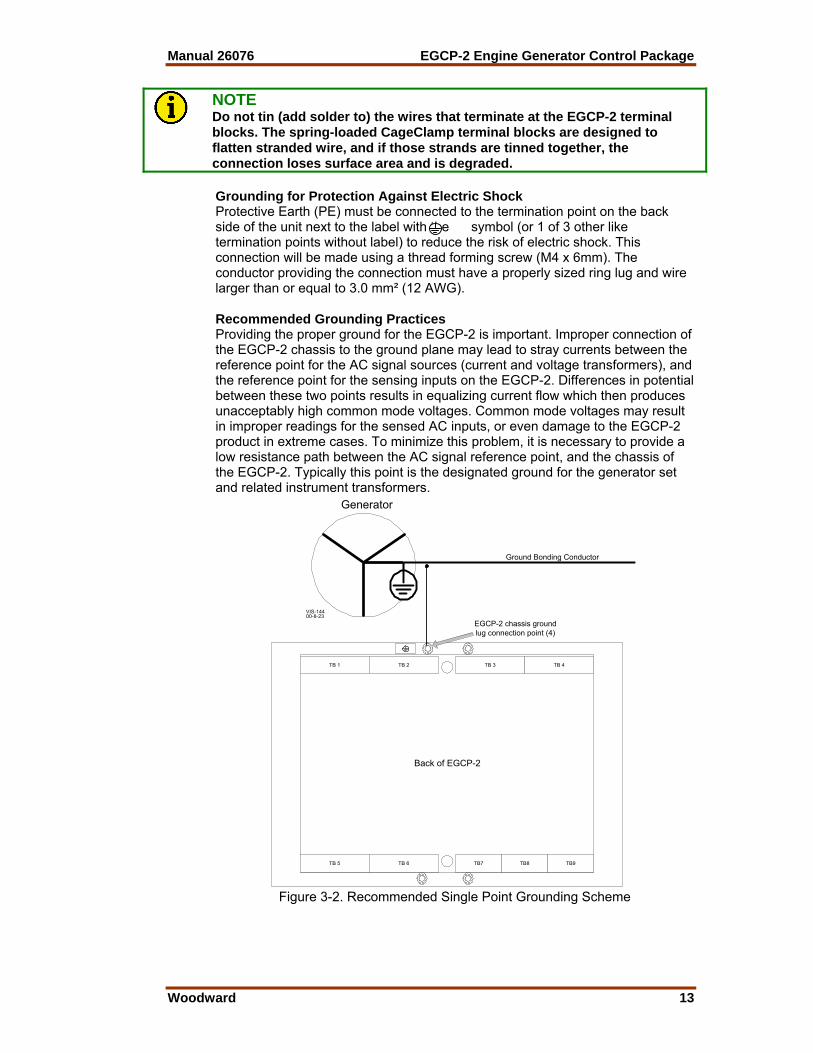
NOTE Do not tin (add solder to) the wires that terminate at the EGCP-2 terminal blocks. The spring-loaded CageClamp terminal blocks are designed to flatten stranded wire, and if those strands are tinned together, the connection loses surface area and is degraded. Grounding for Protection Against Electric Shock Protective Earth (PE) must be connected to the termination point on the back side of the unit next to the label with the symbol (or 1 of 3 other like termination points without label) to reduce the risk of electric shock. This connection will be made using a thread forming screw (M4 x 6mm). The conductor providing the connection must have a properly sized ring lug and wire larger than or equal to 3.0 mm² (12 AWG). Recommended Grounding Practices Providing the proper ground for the EGCP-2 is important. Improper connection of the EGCP-2 chassis to the ground plane may lead to stray currents between the reference point for the AC signal sources (current and voltage transformers), and the reference point for the sensing inputs on the EGCP-2. Differences in potential between these two points results in equalizing current flow which then produces unacceptably high common mode voltages. Common mode voltages may result in improper readings for the sensed AC inputs, or even damage to the EGCP-2 product in extreme cases. To minimize this problem, it is necessary to provide a low resistance path between the AC signal reference point, and the chassis of the EGCP-2. Typically this point is the designated ground for the generator set and related instrument transformers.
Back of EGCP-2
TB 1 TB 2 TB 3 TB 4
TB 5 TB 6 TB7 TB8 TB9
EGCP-2 chassis groundlug connection point (4)
Generator
Ground Bonding Conductor
VIS-14400-8-23
Figure 3-2. Recommended Single Point Grounding Scheme

EGCP-2 Engine Generator Control Package Manual 26076
14 Woodward
Shields and Grounding An individual shield termination is provided at the terminal block for each of the signals requiring shielding except for oil pressure and coolant temperature. All of these inputs should be wired using shielded, twisted-pair wiring. The exposed wire length, beyond the shield, should be limited to one inch. Relay outputs, contact inputs, and power supply wiring do not normally require shielding, but can be shielded if desired. The EGCP-2 is designed for shield termination to earth ground at the EGCP-2. If intervening terminal blocks are used in routing a signal, the shield should be continued through the terminal block. If shield grounding is desired at the terminal block, it should be ac coupled to earth. All other shield terminations except at the EGCP-2 should be ac coupled to earth through a capacitor. A 1000 pF, 500 V capacitor is sufficient. The intent is to provide a low impedance path to earth for the shield at frequencies of 150 kHz and up. Multiple direct connections of a shield to earth risk high levels of current to flow within the shield (exception, see note on cabinet installations). Shields can be grounded at both ends (EGCP-2 and load) if the cable length is sufficiently short (that is, within a cabinet) to prevent ground loop current in the shield. Cabinet Installations: If the EGCP-2 is installed in a cabinet, shielded I/O can be terminated directly to the cabinet (earth ground) at the entry to the cabinet, as well as at the EGCP-2. For noise suppression reasons, it is recommend that all low-current wires be separated from all high-current wires. Input Power ground terminal should also be wired to earth ground.

Manual 26076 EGCP-2 Engine Generator Control Package
Woodward 15
Figure 3-3. Wiring Diagram for EGCP-2

EGCP-2 Engine Generator Control Package Manual 26076
16 Woodward
4 3 2 1
Dip Switch # 2
1 2 3 4
Dip Switch # 4 1 2 3 4
Dip Switch # 3
4 3 2 1
Dip Switch # 1
TB 1 TB 2 TB 3 TB 4
TB 5 TB 6 TB7 TB8 TB9
Back ViewEGCP-2
DIP Switch Identification(not to scale).
DIP SWITCHES ARE ACCESSABLE THROUGH HOLES IN THE SIDES OF THEBACK COVER.
SW - 4RS - 485 Terminations
___________________________4. 4-20 mA Process Input3. 123 ohm RS-485 Termination -2. 123 ohm RS-485 Termination+1. +5V RS-485
SW - 3RS-422 Terminations
___________________________4. No Function.3. 123 ohm RS-422 Termination -2. 123 ohm RS-422 Termination+1. +5V RS-422
SW-2Temperature Sensor Input Hardware______________________________
1. 0-200 Sensor.2. 4-20mA Input Select.3. 100 ohm dropping resistor Select.4. 100 ohm dropping resistor Select.
SW-1Pressure Sensor Input Hardware
______________________________1. 0-200 Sensor.2. 4-20mA Input Select.3. 100 ohm dropping resistor Select.4. 100 ohm dropping resistor Select.
CLOSED
VIS-14301-03-16
1 2 3 4
OPEN 1, 3, 4 = OPEN2 = CLOSED
NOTE: OPEN = UP, away from PC board. CLOSED = DOWN, toward PC board
Figure 3-4. Dip Switch Location
NOTE In the drawing above, the switches will do the mentioned functions when in the CLOSED position.
Input Power The EGCP-2 accepts any input power source that supplies a voltage within the 9-32 Vdc voltage range. It is expected that the installation of this equipment will include overcurrent protection between the power source and the EGCP-2. This overcurrent protection may be accomplished by series connection of properly rated fuses or circuit breakers (see the Input Power Ratings below for proper sizing). Input Power Ratings Part Number: 8406-115 and 116 Supply Voltage Rating Nominal Voltage Range: 10–29 Vdc Maximum Voltage Range: 9–32 Vdc Maximum Power: 20 W Typical Power: 13 W Input Fuse Rating: 5 A (time delay with melting I²t ≥ 100A²sec) Wire Size: Up to 12 AWG Holdup Time: 5 milliseconds @ 24 Vdc Significant inrush currents are possible when current is applied to the EGCP-2 control. The magnitude of the inrush current depends on the power source impedance, so Woodward cannot specify the maximum inrush current. Time-delay fuses or circuit breakers must be used to avoid nuisance trips.
Manual 26076 EGCP-2 Engine Generator Control Package
Woodward 17
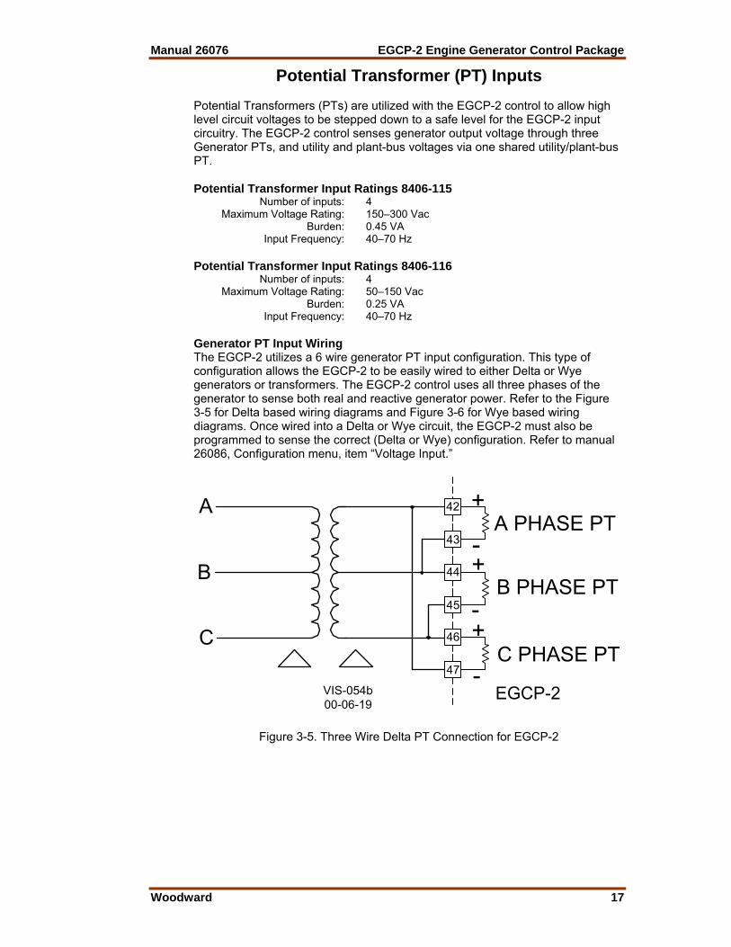
Potential Transformer (PT) Inputs Potential Transformers (PTs) are utilized with the EGCP-2 control to allow high level circuit voltages to be stepped down to a safe level for the EGCP-2 input circuitry. The EGCP-2 control senses generator output voltage through three Generator PTs, and utility and plant-bus voltages via one shared utility/plant-bus PT. Potential Transformer Input Ratings 8406-115 Number of inputs: 4 Maximum Voltage Rating: 150–300 Vac Burden: 0.45 VA Input Frequency: 40–70 Hz Potential Transformer Input Ratings 8406-116 Number of inputs: 4 Maximum Voltage Rating: 50–150 Vac Burden: 0.25 VA Input Frequency: 40–70 Hz Generator PT Input Wiring The EGCP-2 utilizes a 6 wire generator PT input configuration. This type of configuration allows the EGCP-2 to be easily wired to either Delta or Wye generators or transformers. The EGCP-2 control uses all three phases of the generator to sense both real and reactive generator power. Refer to the Figure 3-5 for Delta based wiring diagrams and Figure 3-6 for Wye based wiring diagrams. Once wired into a Delta or Wye circuit, the EGCP-2 must also be programmed to sense the correct (Delta or Wye) configuration. Refer to manual 26086, Configuration menu, item “Voltage Input.”
42
43
44
45
46
47
A PHASE PT
B PHASE PT
C PHASE PT
+
+
+
-
-
-EGCP-2VIS-054b
00-06-19
A
B
C
Figure 3-5. Three Wire Delta PT Connection for EGCP-2

EGCP-2 Engine Generator Control Package Manual 26076
18 Woodward
42
43
44
45
46
47
+
+
+
EGCP-2
VIS-055a00-10-17
A B
C
N
N
A
N
B
N
C
N
N
N
Figure 3-6. Four Wire WYE PT Connection
Utility (Mains) and Plant Bus PT Input Wiring The EGCP-2 utilizes one PT input to sense both utility tie-line voltage and plant-bus voltage. This PT input should be the same configuration as the generator PT input. The potential transformer should be the same ratio as the generator PT input. Two Relay outputs are used by the EGCP-2 to select which voltage source to monitor, depending upon the state of the control. The EGCP-2’s control logic is set up to monitor the utility tie voltage during normal operation and local bus voltage when sensing for a dead bus condition or synchronizing the generator to the local bus. Refer to figures 3-7, 3-8a and b, for required input wiring configurations. This type of configuration allows the EGCP-2 to perform a break-before-make relay action when switching between voltage sources to assure that the utility PT and Bus PT never are connected. Sequence of Mains PT Disconnect (DO8) and Local Bus PT Connect (DO7) The EGCP-2 will command a Mains PT disconnect (DO8) when: 1. The EGCP-2 has an “AUTO” discrete input and either
a. A loss of Mains (LOM) is detected or b. A “Run with load” discrete input.
2. The Generator Stable Delay time has been met. 3. The EGCP-2 is in the “Close Gen Breaker” mode. When the Mains PT Disconnect changes state, the EGCP-2 has to measure less than 40 Vac on the Mains/Bus PT input (terminals 40 and 41). If the EGCP-2 measures greater than 40 Vac after the Mains PT Disconnect command was given, the EGCP-2 senses this as a fault and will not synchronize. For this reason, when only one PT signal is being connected, the external relay logic to remove the incoming Mains/Bus PT signal must still be applied (Figure 3-8a).

Manual 26076 EGCP-2 Engine Generator Control Package
Woodward 19
40
41
Mains/Bus P
Mains PT
K1-B
Mains PTDisconnect(NormallyClosed)(D08)
Local Bus PTConnect(Normally
Open)(D07)
23
24
VIS-14501-05-21
(+V)
K2-B
A
B or NK1-A
K2-A
21
22 (+V)
EGCP-2
K1*
K2*
A
Bus PTA
B or NB or N
(B for Delta, N for Wye)
(B for Delta, N for W
(B for Delta, N for Wye)
- *K1 SHOWN ENERGIZED - *K2 SHOWN DE-ENERGIZED- *K1 & K2 RELAYS ARE NOT
NOTES:
SUPPLIED BY WOODWARD- *K1 and K2 RELAYS SHOULD BE CONNECTED AS NORMALLY OPEN CONTACTS
Multiple EngineLOM's Applications
Figure 3-7. Utility / Local Bus PT Wiring for Delta and Wye Configuration
Please Note: 1. This wiring diagram must be used when sensing Loss of Mains (LOM) with
multiple units. 2. K1 and K2 relays are not supplied by Woodward. 3. K1 and K2 relays should be connected as normally open contacts
NOTE Because the same EGCP-2 input is used to sense both the utility and local bus voltages, the two PT signals must be identical in configuration (WYE or Delta), phase (A-B or A-N), and amplitude for correct input readings.
EGCP-2 Engine Generator Control Package Manual 26076
20 Woodward
Mains/BusPT 40
41
Mains/Bus PT Input
K1-B
Mains PTDisconnect(NormallyClosed)(D08)
Local Bus PTConnect(Normally
Open)(D07)
23
24
VIS-14601-01-31
(+V)
K2-B
A
B or NK1-A
K2-A
21
22 (+V)
EGCP-2
K1*
K2*
A
B or N
(B for Delta, N for Wye)
(B for Delta, N for Wye)
- *K1 SHOWN ENERGIZED - *K2 SHOWN DE-ENERGIZED- *K1 & K2 RELAYS ARE NOT
NOTES:
SUPPLIED BY WOODWARD- *K1 & K2 RELAYS SHOULD BE CONNECTED AS NORMALLY OPEN CONTACTS
Prime Power orSingle
Engine LOMs Applications
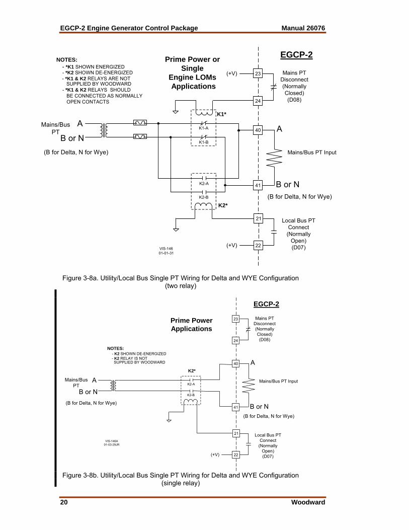
Figure 3-8a. Utility/Local Bus Single PT Wiring for Delta and WYE Configuration
(two relay)
Mains/BusPT
40
41
Mains/Bus PT Input
Mains PTDisconnect(NormallyClosed)(D08)
Local Bus PTConnect
(NormallyOpen)(D07)
23
24
VIS-146A01-03-29JR
K2-B
A
B or NK2-A
21
22 (+V)
EGCP-2
K2*A
B or N(B for Delta, N for Wye)
(B for Delta, N for Wye)
- K2 SHOWN DE-ENERGIZED- K2 RELAY IS NOT
NOTES:
SUPPLIED BY WOODWARD
Prime PowerApplications
Figure 3-8b. Utility/Local Bus Single PT Wiring for Delta and WYE Configuration
(single relay)

Manual 26076 EGCP-2 Engine Generator Control Package
Woodward 21
Please Note: 1. Figures 3-8a and b PT wiring can only be used in a Prime Power Application. 2. Figure 3-8a can be used for a Single Engine LOMs detection. 3. K1 and K2 relays are not supplied by Woodward. 4. K1 and K2 relays should be connected as normally open contacts Required PT Wiring Relationships The EGCP-2 control uses its programmed PT-Ratio setting to calculate and compare all PT input voltages. Thus, the EGCP-2 control requires the following generator, utility, and plant-bus PT relationships. Refer to Figures 3-9 and 3-10.
Gen PTInputs
Voltage Input: Delta
A B C
A+
A-B+
B-C+
C-
480 V 120 V
480 V 120 V
PT Ratio : 4:1Voltage Ref: 480 Vac, L-L
VIS-14701-03-16
Mains/BusPT Input
N
Mains Disconnect
Bus Connect
40
47
46
45
44
43
42
41
EGCP-28406-116
A
B
A
CB
A
B
480 V 120 VA
B
A B CUtilityBus
480 VLL
UtilityBreaker
GeneratorBreaker
GeneratorBus
LocalBus
120 V
120 V
120 V
120 V
Figure 3-9a. PT Wiring Relationships for Generator, Bus, and Utility Inputs
Please Note: 1. This drawing shows EGCP-2 part number 8406-116. 2. Follow Utility/Local Bus PT wiring.

EGCP-2 Engine Generator Control Package Manual 26076
22 Woodward
Voltage Input: Delta
A B C
A+
A-B+
B-C+
C-
480 V 240 V
480 V 240 V
PT Ratio : 2:1Voltage Ref: 480 Vac, L-L
Gen PTInputs
VIS-147a01-03-16
Mains/BusPT Input
N
Mains Disconnect
Bus Connect
40
47
46
45
44
43
42
41
EGCP-28406-115
A
B
A
CB
A
B
480 V 240 VA
B
A B CUtilityBus
480 VLL
UtilityBreaker
GeneratorBreaker
GeneratorBus
LocalBus
240 V
240 V
240 V
240 V
Figure 3-9b. PT Wiring Relationships for Generator, Bus, and Utility Inputs Please Note: 1. This drawing shows EGCP-2 part number 8406-115. 2. Follow Utility/Local Bus PT wiring.
Manual 26076 EGCP-2 Engine Generator Control Package
Woodward 23
CBAN
40
A+
NB+
NC+
N
PT Ratio : 4:1Voltage Input: Wye
Voltage Ref: 277 Vac, L-N
Mains/BusPT input
VIS-14801-03-16
Gen PTInputs
Mains Disconnect
Bus Connect
41
45
44
43
42
47
46
A
N
EGCP-28406-116
N
N
N
A
C
B
A
A
N
N
UtilityBus
GeneratorBreaker
UtilityBreaker
GeneratorBus
LocalBus
CBA
69 V
69 V
69 V
69 V
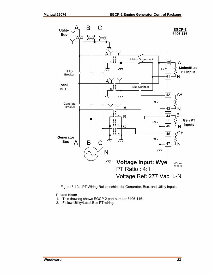
Figure 3-10a. PT Wiring Relationships for Generator, Bus, and Utility Inputs
Please Note: 1. This drawing shows EGCP-2 part number 8406-116. 2. Follow Utility/Local Bus PT wiring.
EGCP-2 Engine Generator Control Package Manual 26076
24 Woodward
CBAN
40
A+
NB+
NC+
N
PT Ratio : 1:1Voltage Input: Wye
Voltage Ref: 277 Vac, L-N
Mains/BusPT input
VIS-148a01-03-29
Gen PTInputs
Mains Disconnect
Bus Connect
41
45
44
43
42
47
46
A
N
EGCP-28406-115
UtilityBus
GeneratorBreaker
UtilityBreaker
GeneratorBus
LocalBus
CBA
277 V
277 V
277 V
277 V
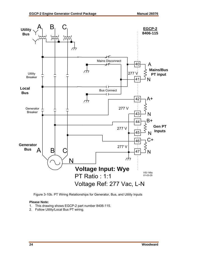
Figure 3-10b. PT Wiring Relationships for Generator, Bus, and Utility Inputs
Please Note: 1. This drawing shows EGCP-2 part number 8406-115. 2. Follow Utility/Local Bus PT wiring.
Manual 26076 EGCP-2 Engine Generator Control Package
Woodward 25
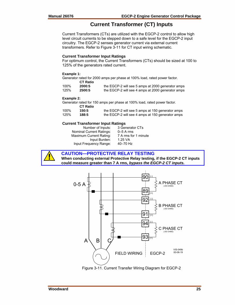
Current Transformer (CT) Inputs Current Transformers (CTs) are utilized with the EGCP-2 control to allow high level circuit currents to be stepped down to a safe level for the EGCP-2 input circuitry. The EGCP-2 senses generator current via external current transformers. Refer to Figure 3-11 for CT input wiring schematic. Current Transformer Input Ratings For optimum control, the Current Transformers (CTs) should be sized at 100 to 125% of the generators rated current. Example 1: Generator rated for 2000 amps per phase at 100% load, rated power factor. CT Ratio 100% 2000:5 the EGCP-2 will see 5 amps at 2000 generator amps 125% 2500:5 the EGCP-2 will see 4 amps at 2000 generator amps Example 2: Generator rated for 150 amps per phase at 100% load, rated power factor. CT Ratio 100% 150:5 the EGCP-2 will see 5 amps at 150 generator amps 125% 188:5 the EGCP-2 will see 4 amps at 150 generator amps Current Transformer Input Ratings Number of Inputs: 3 Generator CTs Nominal Current Ratings: 0–5 A rms Maximum Current Rating: 7 A rms for 1 minute Input Burden: 1.25 VA Input Frequency Range: 40–70 Hz
CAUTION—PROTECTIVE RELAY TESTING When conducting external Protective Relay testing, if the EGCP-2 CT inputs could measure greater than 7 A rms, bypass the EGCP-2 CT inputs.
A B C
0-5 A
FIELD WIRING EGCP-2VIS-049b00-06-19
90A PHASE CT
89(.050 OHMS)
92
91
94
93
B PHASE CT(.050 OHMS)
C PHASE CT(.050 OHMS)
(+)
(-)
(+)
(-)
(+)
(-)
Figure 3-11. Current Transfer Wiring Diagram for EGCP-2
EGCP-2 Engine Generator Control Package Manual 26076
26 Woodward
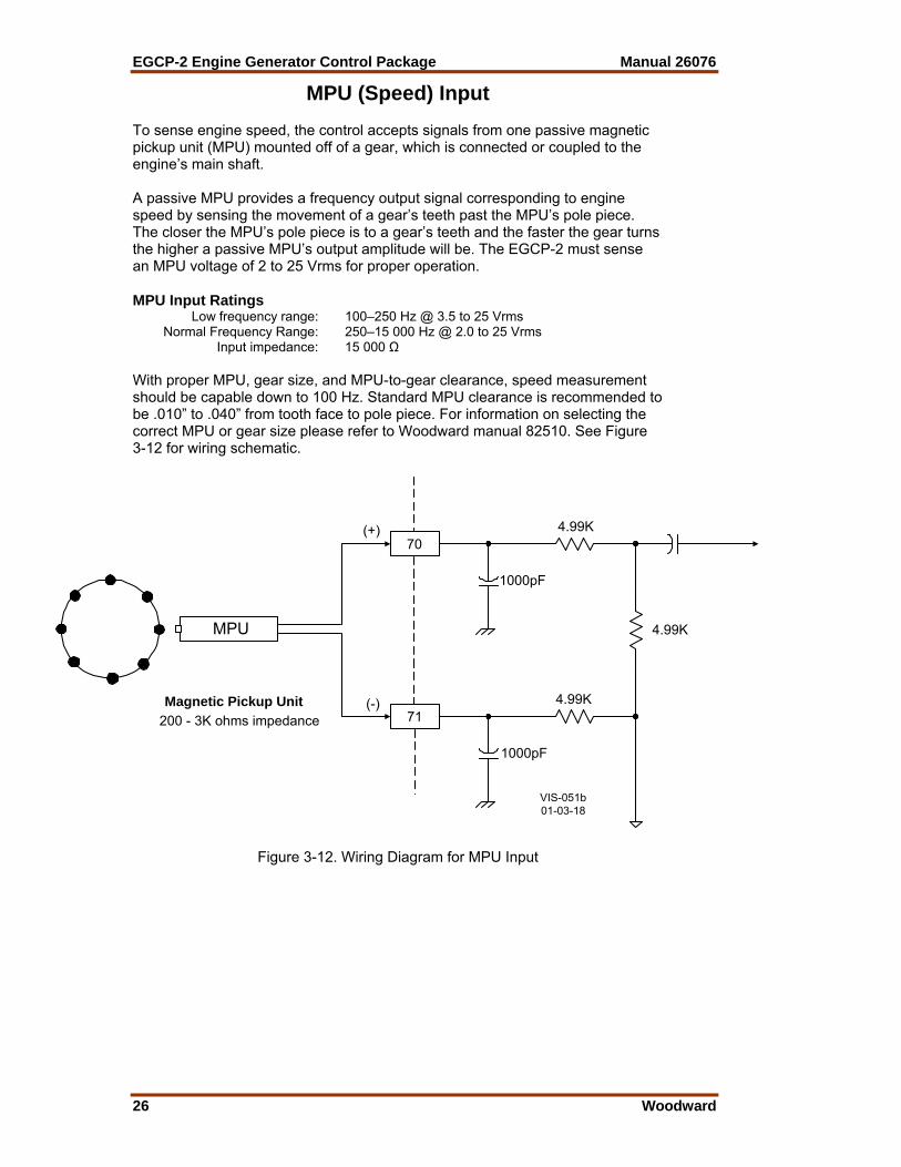
MPU (Speed) Input To sense engine speed, the control accepts signals from one passive magnetic pickup unit (MPU) mounted off of a gear, which is connected or coupled to the engine’s main shaft. A passive MPU provides a frequency output signal corresponding to engine speed by sensing the movement of a gear’s teeth past the MPU’s pole piece. The closer the MPU’s pole piece is to a gear’s teeth and the faster the gear turns the higher a passive MPU’s output amplitude will be. The EGCP-2 must sense an MPU voltage of 2 to 25 Vrms for proper operation. MPU Input Ratings Low frequency range: 100–250 Hz @ 3.5 to 25 Vrms Normal Frequency Range: 250–15 000 Hz @ 2.0 to 25 Vrms Input impedance: 15 000 Ω With proper MPU, gear size, and MPU-to-gear clearance, speed measurement should be capable down to 100 Hz. Standard MPU clearance is recommended to be .010” to .040” from tooth face to pole piece. For information on selecting the correct MPU or gear size please refer to Woodward manual 82510. See Figure 3-12 for wiring schematic.
MPU
Magnetic Pickup Unit200 - 3K ohms impedance
70
71(-)
(+)
1000pF
1000pF
4.99K
4.99K
4.99K
VIS-051b01-03-18
Figure 3-12. Wiring Diagram for MPU Input
Manual 26076 EGCP-2 Engine Generator Control Package
Woodward 27
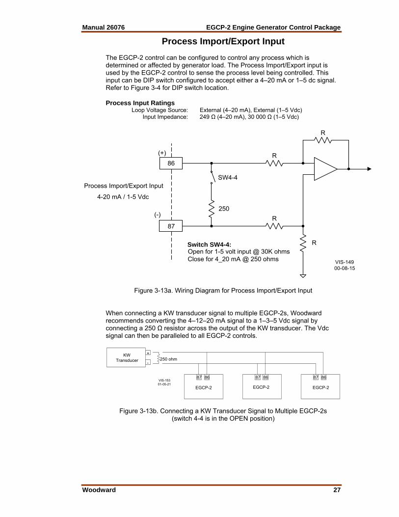
Process Import/Export Input The EGCP-2 control can be configured to control any process which is determined or affected by generator load. The Process Import/Export input is used by the EGCP-2 control to sense the process level being controlled. This input can be DIP switch configured to accept either a 4–20 mA or 1–5 dc signal. Refer to Figure 3-4 for DIP switch location. Process Input Ratings Loop Voltage Source: External (4–20 mA), External (1–5 Vdc) Input Impedance: 249 Ω (4–20 mA), 30 000 Ω (1–5 Vdc)
R
R
R
R
SW4-4
250
87
(-)
(+)86
Process Import/Export Input
4-20 mA / 1-5 Vdc
Switch SW4-4:Open for 1-5 volt input @ 30K ohmsClose for 4_20 mA @ 250 ohms VIS-149
00-08-15
Figure 3-13a. Wiring Diagram for Process Import/Export Input
When connecting a KW transducer signal to multiple EGCP-2s, Woodward recommends converting the 4–12–20 mA signal to a 1–3–5 Vdc signal by connecting a 250 Ω resistor across the output of the KW transducer. The Vdc signal can then be paralleled to all EGCP-2 controls.
+
-
87 8687 8687 86
KWTransducer
EGCP-2
250 ohm
EGCP-2 EGCP-2
VIS-15301-05-21
Figure 3-13b. Connecting a KW Transducer Signal to Multiple EGCP-2s (switch 4-4 is in the OPEN position)

EGCP-2 Engine Generator Control Package Manual 26076
28 Woodward
Coolant Temperature and Oil Pressure Inputs The EGCP-2 has one analog input dedicated to sense engine coolant temperature and one analog input dedicated to sense engine oil pressure. These inputs are optional and once connected-to can be configured to protect the engine by causing a system soft shutdown, hard shutdown, or alarm. To disable these inputs set all related Shutdown/Alarm settings to their “disabled” state. These inputs can be DIP switch configured to be compatible with 0–200 Ω sensors, 4–20 mA transducers, or 0–5 Vdc transducers. Depending on where a 0–200 Ω sensor’s linear range is, this input can also be DIP switch configured to vary sensor loading which will move the sensor output into the most linear part of its range. Refer to Figure 3-4 for DIP switch location and to Figure 3-14 for input wiring schematics. Temperature and Pressure Input Ratings Number of Channels: 2 Loop Voltage Source: Internal Input Impedance: Switch Dependant (refer to Figure 3-14)
R
R
SW1-4 C
R
SW1-3
537.5
100 100
68
+12 Vdc
Oil PressureSensorInput
69
SW1-1
SW 1-2
249
+
-
X - May be closed to insert 100 ohm shuntresistors required to make certain 0-200
ohm transducers more linear.DO NOT CLOSE FOR VOLTAGE OR
CURRENT INPUTS.
Input 4-20mA 1-5 Volt 200 Ohm SensorSW1-1 Open Open ClosedSW1-2 Closed Open OpenSW1-3 Open Open XSW1-4 Open Open X
VIS-050a00-08-24
Figure 3-14a. Wiring Diagram for Pressure Inputs

Manual 26076 EGCP-2 Engine Generator Control Package
Woodward 29
X - May be closed to insert 100 ohm shuntresistors required to make certain 0-200
ohm transducers more linear.DO NOT CLOSE FOR VOLTAGE OR
CURRENT INPUTS.
VIS-050b01-01-31
R
R
SW2-4 C
R
SW2-3
537.5
100 100
66
+12 Vdc
CoolantTemperature
SensorInput
67
SW2-1
SW 2-2
249
+
-
Input 4-20mA 1-5 Volt 200 Ohm SensorSW2-1 Open Open ClosedSW2-2 Closed Open OpenSW2-3 Open Open XSW2-4 Open Open X
Figure 3-14b. Wiring Diagram for Temperature Inputs

EGCP-2 Engine Generator Control Package Manual 26076
30 Woodward
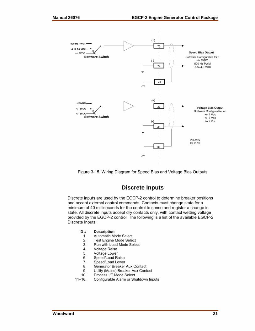
Speed Bias and Voltage Bias Outputs The EGCP-2’s Speed Bias output is a dedicated analog output, which is used to bias the prime mover’s speed control for unit synchronization and load control. The Speed Bias output is software configurable for outputs of ±3 Vdc, 0.5–4.5 Vdc, or 500 Hz PWM. Refer to Chapter 3, configuration menus, in manual 26086 for selection information. ±3 Vdc—Compatible with Woodward analog and digital speed Controls via the Aux Inputs or the load sharing lines on the 2301/2301A LSSC. 0.5-4.5 Vdc—Compatible with the Detroit Diesel Corp. DDEC-III and IV Control and Caterpillar’s Gas Engine Control Module (GECM). 500 Hz PWM—Compatible with Caterpillar’s ADEM control (diesel engine). Refer to Appendix B of this manual for control specific speed bias connections. The EGCP-2’s Voltage Bias output is a dedicated analog output, which is used to bias the generator’s automatic voltage regulator for unit synchronization and reactive load control. The Voltage Bias output is software configurable for outputs of ±1 Vdc, ±3 Vdc, or ±9 Vdc. Refer to Chapter 3, configuration menus, in manual 26086 for selection information. The voltage bias output works with many automatic voltage regulators. Following is a list of manufacturers and types: Basler Caterpiller KATO Newage Leroy Somer SR4A VR3 360 MX321 SR8A DVR 760 MX341 SSE SSR DECS The EGCP-2 is not compatible with the Marathon 2000 DVR. The Speed and Voltage Bias Outputs will only drive into high impedance type inputs, and are limited to inputs, which have an input impedance of 1000 ohms or more. Speed and Voltage Bias output Ratings Number of Channels: 2 Min Drive Impedance: 1000 Ω
Manual 26076 EGCP-2 Engine Generator Control Package
Woodward 31
+/- 3VDC
.5 to 4.5 VDC
500 Hz PWM
74
(-)
(+)
73
Speed Bias OutputSoftware Configurable for :
+/- 3VDC 500 Hz PWM .5 to 4.5 VDC
38
(-)
(+)
37 Voltage Bias OutputSoftware Configurable for:
+/- 1 Vdc+/- 3 Vdc+/- 9 Vdc
39
VIS-052a00-04-19
75
Software Switch
Software Switch+/- 1VDC
+/- 3VDC
+/-9VDC
Figure 3-15. Wiring Diagram for Speed Bias and Voltage Bias Outputs
Discrete Inputs Discrete inputs are used by the EGCP-2 control to determine breaker positions and accept external control commands. Contacts must change state for a minimum of 40 milliseconds for the control to sense and register a change in state. All discrete inputs accept dry contacts only, with contact wetting voltage provided by the EGCP-2 control. The following is a list of the available EGCP-2 Discrete Inputs: ID # Description 1. Automatic Mode Select 2. Test Engine Mode Select 3. Run with Load Mode Select 4. Voltage Raise 5. Voltage Lower 6. Speed/Load Raise 7. Speed/Load Lower 8. Generator Breaker Aux Contact 9. Utility (Mains) Breaker Aux Contact 10. Process I/E Mode Select 11–16. Configurable Alarm or Shutdown Inputs

EGCP-2 Engine Generator Control Package Manual 26076
32 Woodward
Discrete Input Ratings Number of Channels: 16 Input Type: Optically isolated Min Closed Sense Time: 40 ms Speed/Load Raise and Lower Inputs The functionality of the Speed/Load Raise and Lower inputs change based on the mode that the EGCP-2 control is in. If the EGCP-2 control is in the Speed control mode (generator breaker open), these contact inputs can be used to raise and lower speed. If the EGCP-2 control is in the Baseload control mode (generator breaker closed, utility tie breaker closed), these contact inputs can be used to raise and lower unit baseload. If the EGCP-2 control is in the Process control mode (Process control enabled), these contact inputs can be used to raise and lower the process setpoint. Refer to figure 8-23 for Speed/Load raise and lower contact functionality matrix. Voltage Raise and Lower Inputs The functionality of the Voltage Raise and Lower inputs change based on the mode that the EGCP-2 control is in. If the EGCP-2 control is in the Speed control mode (generator breaker open), these contact inputs can be used to raise and lower unit voltage. If the EGCP-2 control is in the VAR control mode (VAR control programmed, generator breaker closed, utility tie breaker closed), these contact inputs can be used to raise and lower unit VARs. If the EGCP-2 control is in the Power Factor control mode (Power Factor control programmed, generator breaker closed, utility tie breaker closed), these contact inputs can be used to raise and lower unit Power Factor. If the EGCP-2 control is in the isochronous load sharing mode, the Voltage Raise and Lower inputs are disabled. Gen, Tie, Alarm, and Shutdown Inputs The Generator Breaker contact input must be wired so it is closed when the generator breaker is closed. The Utility Tie Breaker contact input must be wired so it is closed when the utility tie breaker is closed. The Configurable Alarm or Shutdown Inputs must be wired so they are closed when the alarm or shutdown condition is true.
Manual 26076 EGCP-2 Engine Generator Control Package
Woodward 33
R
+5 Vdc
+V
49
Auto/Manual
65
Discrete Input Common
User Supplied Contact
R
Typical Example of Discrete Input(Auto/Manual Contact (DI#1) Input Shown)
Note:TB6-65 is the discrete input common for
all contact inputs
VIS-053a00--06-19
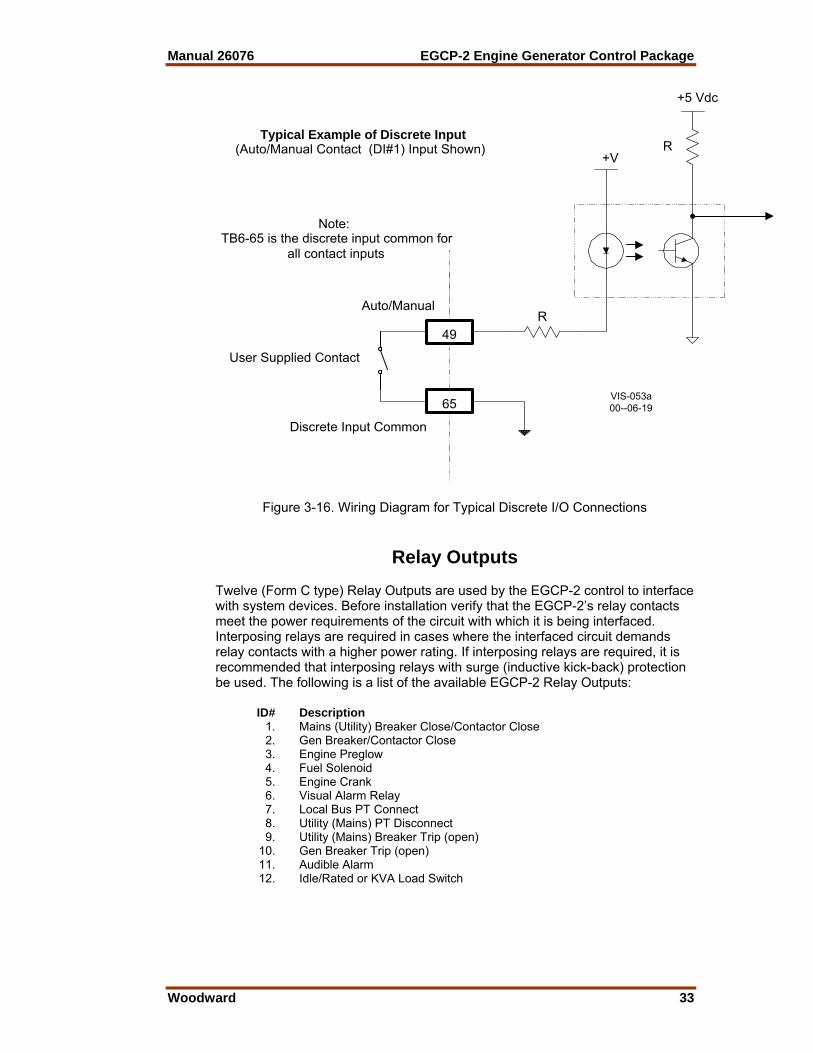
Figure 3-16. Wiring Diagram for Typical Discrete I/O Connections
Relay Outputs Twelve (Form C type) Relay Outputs are used by the EGCP-2 control to interface with system devices. Before installation verify that the EGCP-2’s relay contacts meet the power requirements of the circuit with which it is being interfaced. Interposing relays are required in cases where the interfaced circuit demands relay contacts with a higher power rating. If interposing relays are required, it is recommended that interposing relays with surge (inductive kick-back) protection be used. The following is a list of the available EGCP-2 Relay Outputs: ID# Description 1. Mains (Utility) Breaker Close/Contactor Close 2. Gen Breaker/Contactor Close 3. Engine Preglow 4. Fuel Solenoid 5. Engine Crank 6. Visual Alarm Relay 7. Local Bus PT Connect 8. Utility (Mains) PT Disconnect 9. Utility (Mains) Breaker Trip (open) 10. Gen Breaker Trip (open) 11. Audible Alarm 12. Idle/Rated or KVA Load Switch
EGCP-2 Engine Generator Control Package Manual 26076
34 Woodward
Relay Output Ratings Number of Channels: 12 Relay Type: Sealed Relay Response Time: 15 ms (operate and release) Relay Life Expectancy: ≥50 000 operations @ rated load (8 A @ 250 Vac
COS ≥0.7) (8 A @ 24 Vdc τ ≥0.7 ms) Replaceability: Relays are soldered to main board and are not field
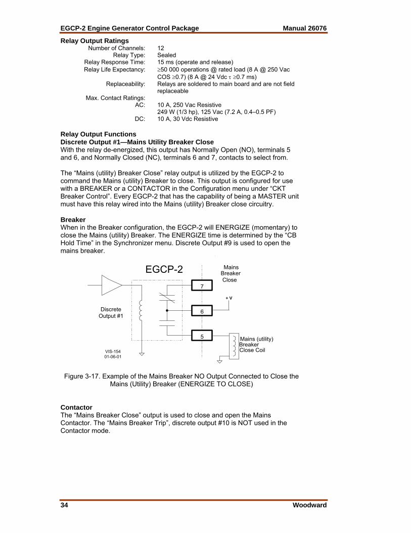
replaceable Max. Contact Ratings: AC: 10 A, 250 Vac Resistive 249 W (1/3 hp), 125 Vac (7.2 A, 0.4–0.5 PF) DC: 10 A, 30 Vdc Resistive Relay Output Functions Discrete Output #1—Mains Utility Breaker Close With the relay de-energized, this output has Normally Open (NO), terminals 5 and 6, and Normally Closed (NC), terminals 6 and 7, contacts to select from. The “Mains (utility) Breaker Close” relay output is utilized by the EGCP-2 to command the Mains (utility) Breaker to close. This output is configured for use with a BREAKER or a CONTACTOR in the Configuration menu under “CKT Breaker Control”. Every EGCP-2 that has the capability of being a MASTER unit must have this relay wired into the Mains (utility) Breaker close circuitry. Breaker When in the Breaker configuration, the EGCP-2 will ENERGIZE (momentary) to close the Mains (utility) Breaker. The ENERGIZE time is determined by the “CB Hold Time” in the Synchronizer menu. Discrete Output #9 is used to open the mains breaker.
5
DiscreteOutput #1
7
6
MainsBreakerClose
VIS-15401-06-01
EGCP-2
+ V
Mains (utility)BreakerClose Coil
Figure 3-17. Example of the Mains Breaker NO Output Connected to Close the
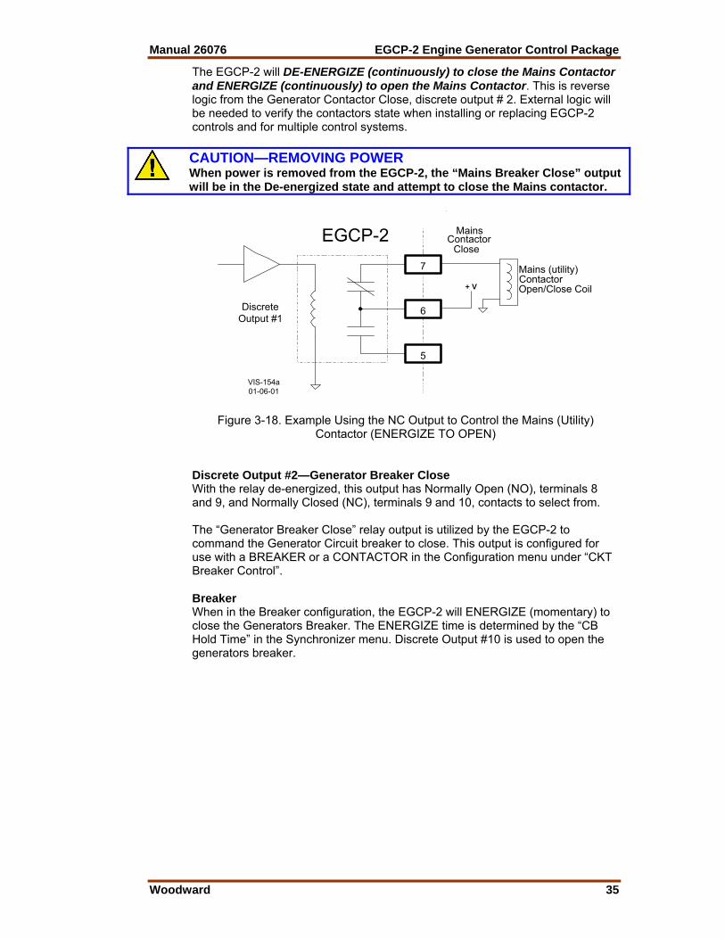
Mains (Utility) Breaker (ENERGIZE TO CLOSE) Contactor The “Mains Breaker Close” output is used to close and open the Mains Contactor. The “Mains Breaker Trip”, discrete output #10 is NOT used in the Contactor mode.
Manual 26076 EGCP-2 Engine Generator Control Package
Woodward 35
The EGCP-2 will DE-ENERGIZE (continuously) to close the Mains Contactor and ENERGIZE (continuously) to open the Mains Contactor. This is reverse logic from the Generator Contactor Close, discrete output # 2. External logic will be needed to verify the contactors state when installing or replacing EGCP-2 controls and for multiple control systems.
CAUTION—REMOVING POWER When power is removed from the EGCP-2, the “Mains Breaker Close” output will be in the De-energized state and attempt to close the Mains contactor.
5
DiscreteOutput #1
7
6
MainsContactor
Close
VIS-154a01-06-01
EGCP-2
+ V
Mains (utility)ContactorOpen/Close Coil
Figure 3-18. Example Using the NC Output to Control the Mains (Utility) Contactor (ENERGIZE TO OPEN)
Discrete Output #2—Generator Breaker Close With the relay de-energized, this output has Normally Open (NO), terminals 8 and 9, and Normally Closed (NC), terminals 9 and 10, contacts to select from. The “Generator Breaker Close” relay output is utilized by the EGCP-2 to command the Generator Circuit breaker to close. This output is configured for use with a BREAKER or a CONTACTOR in the Configuration menu under “CKT Breaker Control”. Breaker When in the Breaker configuration, the EGCP-2 will ENERGIZE (momentary) to close the Generators Breaker. The ENERGIZE time is determined by the “CB Hold Time” in the Synchronizer menu. Discrete Output #10 is used to open the generators breaker.

EGCP-2 Engine Generator Control Package Manual 26076
36 Woodward
8
DiscreteOutput #2
10
9
GeneratorBreakerClose
VIS-154b01-06-01
EGCP-2
+ V
GeneratorBreakerClose Coil
Figure 3-19. Example of the Generator Breaker Close NO Output Connected to
Close the Generator Breaker (ENERGIZE TO CLOSE) Contactor The “Generator Breaker Close” output is used to close and open the Generators Contactor. The “Generator Breaker Trip”, discrete output #10, is NOT used in the Contactor mode. The EGCP-2 will DE-ENERGIZE (continuously) to open the Generators Contactor and ENERGIZE (continuously) to close the Generators Contactor. This is reverse logic from the Mains Contactor Close, discrete output # 1.
8
DiscreteOutput #2
10
9
GeneratorContactorClose
VIS-154c01-06-01
EGCP-2
+ V
GeneratorContactorOpen/Close Coil
Figure 3-20. Example Using the NO Contacts to Control the Generator’s Contactor (ENERGIZE TO CLOSE)

Manual 26076 EGCP-2 Engine Generator Control Package
Woodward 37
Discrete Output #3—Engine Preglow The “Engine Preglow” relay output utilizes a set of normally open (NO) contacts on terminals 11 and 12. The “Engine Preglow” relay output is utilized by the EGCP-2 to turn on a diesel engine’s glow plugs, if so equipped. This relay will energize for a programmed length of time, based on the “Preglow Time” setting, before an engine crank command is given. Discrete Output #4—Fuel Solenoid The “Fuel Solenoid” relay output utilizes a set of Normally Open (NO) contacts on terminals 13 and 14 to energize the engine’s fuel solenoid. The Configurations menu, “Start Sequencing” setting of Enabled or Disabled, determines the EGCP-2’s start process. Start Sequencing—Enabled This relay ENERGIZES at the same time an Engine Crank command is initiated, and stays on until a shutdown command is received. The EGCP-2 must have a Magnetic Pickup (MPU) signal to operate in this condition. Start Sequencing—Disabled The EGCP-2 will ENERGIZE (continuously) the Fuel Solenoid relay when a start command is given. It will De-energize when a shutdown command is received. The fuel solenoids output will function as a Run/Stop relay. There is no “Engine Preglow” or “Engine Crank” command in this mode. The Disabled mode allows the EGCP-2 to operate without a Magnetic Pickup (MPU) signal. Discrete Output #5—Engine Crank The “Engine Crank” relay output utilizes a set of Normally Open (NO) contacts on terminals 15 and 16. The “Engine Crank” relay output is utilized by the EGCP-2 to command the engine to crank or start. This relay will energize for a programmed length of time, based on the “Crank Time” setting, or until engine speed is sensed to be above the “Crank Cutout” speed setting. Discrete Output #6—Visual Alarm With the relay de-energized, this output has Normally Open (NO) terminals 18 and 19 and Normally Closed (NC) terminals 19 and 20 contacts to select from. The “Visual Alarm” relay output can be utilized as an option to remotely indicate when an alarm condition has been sensed by the EGCP-2 control. This relay energizes upon any sensed alarm condition and will remain energized until all alarm conditions have been acknowledged or committed via the unit’s Alarm Screen. Refer to manual 26086 for information on acknowledging and committing alarms.
EGCP-2 Engine Generator Control Package Manual 26076
38 Woodward
Discrete Output #7—Local Bus PT Connect The “Local Bus PT Connect” relay utilizes a set of Normally Open (NO) contacts on terminals 21 and 22. The “Local Bus PT connect” relay output is utilized by the EGCP-2 to connect the Local Bus PT to the EGCP-2’s “Utility and Local Bus PT Input” on terminals 40 and 41. Due to relay load limitations, it is required that this output be configured to drive an interposing relay with which to control the Local Bus PT connection. Refer to Figures 3-7 and 3-8a and b of this chapter for detailed wiring information. This type of relay configuration allows a break-before-make action, insuring that the Utility Tie PT and the Local Bus PT are never connected. Discrete Output #8—Utility Tie (Mains) PT Disconnect The “Utility Tie (Mains) PT Disconnect” relay utilizes a set of Normally Open (NO) contacts on terminals 23 and 24. The “Utility Tie (Mains) PT disconnect” relay output is utilized by the EGCP-2 to disconnect the Utility PT from the EGCP-2’s “Utility and Local Bus PT Input” on terminals 40 and 41. Due to relay load limitations, it is required that this output be configured to drive an interposing relay with which to control the Utility Tie PT connection. Refer to Figures 3-7 and 3-8a and b of this chapter for detailed wiring information. This type of relay configuration allows a break-before-make action, insuring that the Utility Tie PT and the Local Bus PT are never connected. Discrete Output #9—Mains Breaker Trip (Open) With the relay de-energized, this output has Normally Open (NO), terminals 25 and 26, and Normally Closed (NC), terminals 26 and 27, contacts to select from. The “Mains Breaker Trip (open)” relay output is utilized by the EGCP-2 to command the Mains (utility) Breaker to open. This output is operational when configured for use with a BREAKER, in the Configuration menu under “CKT Breaker Control”. If configured for Contactor, see Discrete Output #1 for Mains Contactor open/close operation. Every EGCP-2 that has the capability of being a MASTER unit must have this relay wired into the Mains (utility) Breaker open circuitry. Breaker When in the Breaker configuration, the EGCP-2 will ENERGIZE (momentary) to open the Mains (utility) Breaker.

Manual 26076 EGCP-2 Engine Generator Control Package
Woodward 39
25
DiscreteOutput #9
27
26
MainsBreakerTrip
VIS-154d01-06-01
EGCP-2
+ V
MainsBreakerTrip (Open) Coil
Figure 3-21. Example Using the NO Contacts to Control the Mains Breaker Trip
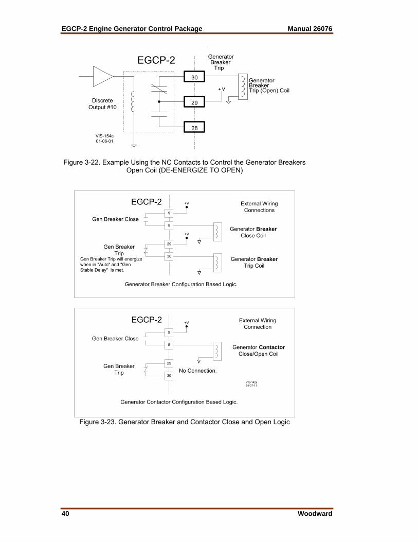
(Open) Coil (ENERGIZE TO OPEN) Discrete Output #10—Generator Breaker Trip (Open) With the relay de-energized, this output has Normally Open (NO), terminals 28 and 29, and Normally Closed (NC), terminals 29 and 30, contacts to select from. The “Generator Breaker Trip (open)” relay output is utilized by the EGCP-2 to command the Generator Breaker to open. The relay output will DE-ENERGIZE to open the Generator Breaker. This output is operational when configured for use with a BREAKER, in the Configuration menu under “CKT Breaker Control”. If configured for Contactor, see Discrete Output #2 for Generator Contactor open/close operation. Breaker In the Breaker configuration, the “Generator Breaker Trip (open)” relay will energize when the EGCP-2 is: 1. In the “AUTO” mode (Discrete Input #1) 2. And the Generator is stable (Generator Stable Delay time has been
achieved) The EGCP-2 will DE-ENERGIZE to open the Generators Breaker. The output will stay de-energized until the “AUTO” and Generator stable conditions are met. When operating in the Manual mode, it is required to externally control the Generators Breaker. The EGCP-2 will continuously be providing a Generator Breaker open command. This means the EGCP-2 will have no control over opening the generators breaker once it has been closed manually. See Chapter 8 for Manual operation details.
EGCP-2 Engine Generator Control Package Manual 26076
40 Woodward
28
DiscreteOutput #10
30
29
GeneratorBreaker
Trip
VIS-154e01-06-01
EGCP-2
+ V
GeneratorBreakerTrip (Open) Coil
Figure 3-22. Example Using the NC Contacts to Control the Generator Breakers
Open Coil (DE-ENERGIZE TO OPEN)
No Connection.
9
8
29
30
Gen Breaker Close
Gen BreakerTrip
Generator BreakerClose Coil
Generator BreakerTrip Coil
Generator Breaker Configuration Based Logic.
EGCP-2
External WiringConnection
External WiringConnections
VIS-142a01-07-11
+V
+V
9
8
29
30
Gen Breaker Close
Gen BreakerTrip
EGCP-2 +V
Generator ContactorClose/Open Coil
Generator Contactor Configuration Based Logic.
Gen Breaker Trip will energizewhen in "Auto" and "GenStable Delay" is met.
Figure 3-23. Generator Breaker and Contactor Close and Open Logic
Manual 26076 EGCP-2 Engine Generator Control Package
Woodward 41
Discrete Output #11—Audible Alarm With the relay de-energized, this output has Normally Open (NO) terminals 31 and 32 and Normally Closed (NC) terminals 32 and 33 contacts to select from. The “Audible Alarm” relay output can be utilized as an option to control a plant Alarm Horn to indicate when an alarm condition has been sensed by the EGCP-2 control. This relay energizes upon any sensed alarm condition and will remain energized until an acknowledged command is given. Refer to manual 26086 for information on acknowledging and committing alarms. When an alarm setpoint is configured for Audible Alarm, the alarm condition will cause the audible and visual alarm output relays to energize and the red LED on the face of the EGCP-2 to flash. All alarm indicators will remain active until the alarm condition is acknowledged. No control actions occur as a result of an audible alarm condition. Discrete Output #12—KVA Load or Idle/Rated Switch This relay uses Normally Open (NO) contacts at terminal 34 and 35. Discrete Output #12 can be configured for a “KVA Load” or an “Idle/Rated” switch. This selection is done in the Configuration menu under “Relay #12 Function”. KVA Load Switch This relay will energize when the controls KVA value is within the configured Low and High settings. The relay will de-energize when the KVA value is below or above the configured Low and High settings. The low and high setpoints are configured in the Real Load Control menu, under items “KVA Switch Low” and “KVA Switch High”. Idle/Rated Switch When selected as an Idle/Rated switch, the output must be connected to the engines speed control. This relay is de-energized to select an idle speed settings, and after reaching the set idle speed value and holding at that point for the set amount of time, the relay energizes to select the speed controls rated speed setting. The speed value and time are configured in the Engine Control menu under items “Idle Speed” and “Idle Time”. The engines idle speed must be equal to or greater than the configured “Idle Speed” value to start the “Idle Time”. The EGCP-2 uses the magnetic pickup (MPU) signal to calculate the idle speed. If no MPU is connected, the idle speed is calculated from the Generators frequency. Remember, if the generator is NOT excited at idle speed and there is no MPU signal, the Idle/Rated switch will not energize. When a Loss of Mains (LOM) or an overloaded system condition exists, the idle/rated function is bypassed, and rated speed is selected during the start sequencing routine.

EGCP-2 Engine Generator Control Package Manual 26076
42 Woodward
AC Inputs The EGCP-2 receives ac inputs from the generator, bus, mains and engine. They are as follows: Location Description Signal Burden 42 Generator PT phase A + AC Voltage 200 kΩ 43 Generator PT phase A – AC Voltage A+ to A– 44 Generator PT phase B + AC Voltage 200 kΩ 45 Generator PT phase B – AC Voltage B+ to B– 46 Generator PT phase C + AC Voltage 200 kΩ 47 Generator PT phase C – AC Voltage C+ to C– 89 Generator CT phase A+ Current AC Current 0.050 Ω 90 Generator CT phase A– Current AC Current + to – 91 Generator CT phase B+ Current AC Current 0.050 Ω 92 Generator CT phase B– Current AC Current + to – 93 Generator CT Phase C+ Current AC Current 0.050 Ω 94 Generator CT Phase C– Current AC Current + to - 40 Mains/Bus PT Phase A AC Voltage 200 k Ω 41 Mains/Bus PT Phase B or N AC Voltage + to – 70 Magnetic Pickup + AC Frequency 15 k Ω 71 Magnetic Pickup – AC Frequency + to – 72 Magnetic Pickup Shield
DC Inputs and Outputs Location Description Signal I/O 1 + power supply 9–32 Vdc Isolated 2 – power supply Input 13 W typical, 20 W max. 86 + Process Signal 4–20 mA Isolated Input 87 – Process Signal or 1–5 Vdc 249 Ω (4–20 mA) 88 Process Signal Shield 30 k Ω (1–5 Vdc) 73 + Speed Bias ±3 Vdc, Software Configured 74 – Speed Bias 0.5 to 4.5 Vdc, 10 mA Maximum 75 Speed Bias Shield 500 Hz PWM Isolated Output 37 + Voltage Bias ±1, 3, or 9 Vdc Software Configured 38 – Voltage Bias 10mA Maximum 39 Voltage Bias Shield Isolated Output 68 Pressure Sensor + 0–200 Ω sensor, Internal Voltage Source 69 Pressure Sensor – 4-20 mA, or 1-5 Vdc Internal Source Common Dip Switch Selected 66 Temp Sensor + 0–200 Ω sensor Internal Voltage Source 67 Temp Sensor – 4–20 mA, or 1–5 Vdc Internal Source Common Dip Switch Selected

Manual 26076 EGCP-2 Engine Generator Control Package
Woodward 43
Discrete Inputs Loc. Description Signal Input 49 Auto Discrete Input (DI-1) + power supply (internal connection) 50 Test Discrete Input (DI-2) + power supply (internal connection) 51 Run/Ld Discrete Input (DI-3) + power supply (internal connection) 52 Volt Raise Discrete Input (DI-4) + power supply (internal connection) 53 Volt Lower Discrete Input (DI-5) + power supply (internal connection) 54 Speed Raise Discrete Input (DI-6) + power supply (internal connection) 55 Speed Lower Discrete Input (DI-7) + power supply (internal connection) 56 Gen CB Aux Discrete Input (DI-8) + power supply (internal connection) 57 Mains CB Aux Discrete Input (DI-9) + power supply (internal connection) 58 Process Discrete Input (DI-10) + power supply (internal connection) 59 Fault 1 Discrete Input (DI-11) + power supply (internal connection) 60 Fault 2 Discrete Input (DI-12) + power supply (internal connection) 61 Fault 3 Discrete Input (DI-13) + power supply (internal connection) 62 Fault 4 Discrete Input (DI-14) + power supply (internal connection) 63 Fault 5 Discrete Input (DI-15) + power supply (internal connection) 64 Fault 6 Discrete Input (DI-16) + power supply (internal connection) 65 Switch Common Discrete Input – power supply (internal connection) NOTE: Approximately 5 mA current draw across each DI when CLOSED.
Discrete Outputs Location Description Signal Output Rating 7 Mains Brkr Close NC Discrete Output (D01) (see Relay 6 Mains Brkr Close C (D01) Output Ratings) 5 Mains Brkr Close NO Discrete Output (D01) “ 10 Gen Brkr Close NC Discrete Output (D02) “ 9 Gen Brkr Close C (D02) “ 8 Gen Brkr Close NO Discrete Output (D02) 12 Engine Preglow C (DO3) “ 11 Engine Preglow NO Discrete Output (DO3) “ 14 Fuel Solenoid C (DO4) “ 13 Fuel Solenoid NO Discrete Output (DO4) “ 16 Crank Engine C Discrete Output (DO5) “ 15 Crank Engine NO Discrete Output (DO5) “ 17 No Connection Isolation Boundary 20 Visual Alarm NC Discrete Output (DO6) “ 19 Visual Alarm C (DO6) “ 18 Visual Alarm NO Discrete Output (DO6) 22 Bus PT Connect C (DO7) “ 21 Bus PT Connect NO Discrete Output (DO7) “ 24 Mains PT Disconnect NC Discrete Output (DO8) “ 23 Mains PT Disconnect C (DO8) “ 27 Mains Brkr Trip NC Discrete Output (DO9) “ 26 Mains Brkr Trip C (DO9) “ 25 Mains Brkr Trip NO Discrete Output (DO9) 30 Gen Brkr Trip NC Discrete Output (DO10) “ 29 Gen Brkr Trip C (DO10) “ 28 Gen Brkr Trip NO Discrete Output (DO10) 33 Audible Alarm NC Discrete Output (DO11) “ 32 Audible Alarm C Discrete Output (DO11) “ 31 Audible Alarm NO Discrete Output (DO11)

EGCP-2 Engine Generator Control Package Manual 26076
44 Woodward
Location Description Signal Output Rating 35 Idle Rated/Load SW C (DO12) “ 34 Idle Rated/Load SW NO Discrete Output (DO12) “ 36 No Connection Isolation Boundary
Communication Ports: RS-485 & RS-422 (1 each) Location Description Signal 77 – 485 Communication Inter-control Communications 76 + 485 Communication Inter-control Communications 78 485 Shield 80 +5 Vdc common Internal Isolated Power Supply 79 +5 Vdc Internal Isolated Power Supply 81 422 Communication RX+ PC interface 82 422 Communication RX– PC interface 83 422 Shield 84 422 Communication TX+ PC interface 85 422 Communication TX– PC interface Specifications Communications: RS-422 protocol 9600 Baud (fixed maximum) No Parity 1 Stop Bit Minimum Computer Requirements: Windows 95
Hardware Connections Once the software is installed on the computer hard drive, the hardware connection between the computer and the EGCP-2 control must be made for correct communication between the two devices. This hardware connection is completed using a direct cable connection between the computer and the EGCP-2 control(s) RS-422 network. Modbus/ServLink Communications The laptop or desktop computer which will be used with the EGCP-2 RS-422 port will have a 9-pin serial port. This port is configured by the computer hardware to use a serial communications protocol called RS-232. The details of this protocol are not important to know for hardware connection to the EGCP-2 control(s), other than there is a need to convert the RS-232 protocol of the computer port to RS-422 protocol used by the EGCP-2 control network. This conversion is accomplished via an external conversion module which takes the 9-pin RS-232 serial port input from the computer, and changes it to a RS-422 protocol for the EGCP-2. These converters can be found in most computer or electronics stores, and are called RS-232 to RS-422 Converters. Woodward offers a cable, 5417-551, that includes this converter. This cable is designed for point-to-point communications.

Manual 26076 EGCP-2 Engine Generator Control Package
Woodward 45
In a system with multiple (8 maximum) EGCP-2 controls, each control is interconnected to the others on the 422 network in a multidrop fashion. The computer is linked to the network at any control as if it were the next control on the network, as shown below.
IBM compatible computerPentium based w / Windows '9X or NT 4.0
EGCP-2
Unit #1
81 82
Twisted shielded pair. Belden 3074F or equivalent
85
422Tx(+)
84
83
422Tx(-)
422Rx(-)
422Rx(+)
EGCP-2
Unit #2
81 82 85
422Tx(+)
84
83
422Tx(-)
422Rx(-)
422Rx(+)
EGCP-2
Unit #8
81 82 85
422Tx(+)
84
83
422Tx(-)
422Rx(-)
422Rx(+)
422Rx(+)
422Rx(-)
422Tx(-)
422Tx(+)VIS-107a00-10-20
Figure 3-24. RS-422 Communications
Switch configuration for multiple units utilizing RS-422 communication. Unit #1 Unit #2 Unit #8
SW3-1 Closed SW3-1Open SW3-1 Closed SW3-2 Closed SW3-2 Open SW3-2 Closed SW3-3 Closed SW3-3 Open SW3-3 Closed
NOTES When the RS-422 to RS-232 converter is greater than 30 meters from unit 1, an isolating version will be required. Cable shields must also be AC coupled to earth or connected to RS-422 to RS-232 converter chassis. This chassis must be Isolated from earth and may be AC coupled to earth.
When unit 2 and/or unit 3 are more than 30 meters from unit 1, the cable shield must be ac coupled to terminal 83. The capacitor must be 0.01 µF with a working voltage of 1000 Vdc or greater.
The RS-422 Termination dip switches must be closed on the end units on the network for proper communications. See the plant wiring diagram for switch locations. Failure to terminate the network properly will cause communication drop out errors.
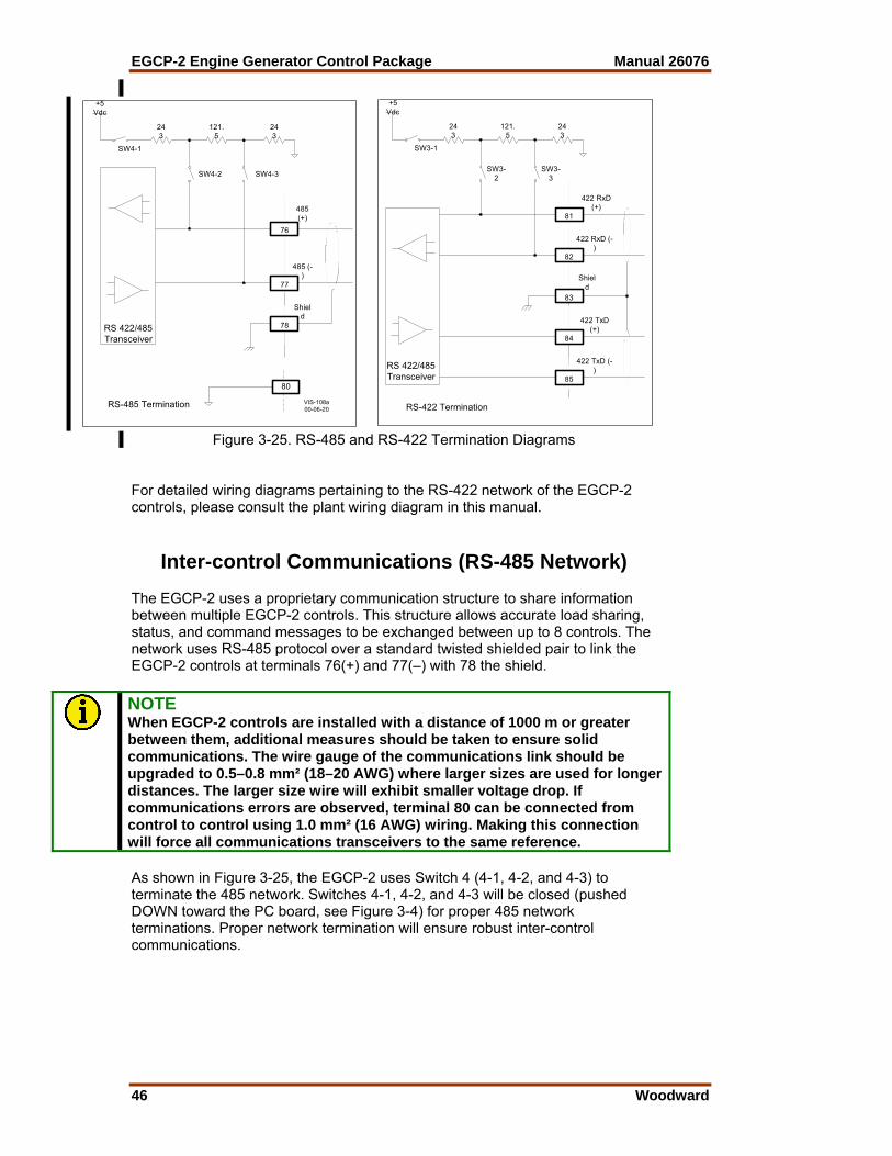
EGCP-2 Engine Generator Control Package Manual 26076
46 Woodward
76
77
485(+)
RS-485 Termination
485 (-)
243
SW4-1
+5Vdc
SW4-2 SW4-3
121.5
243
78
Shield
RS 422/485Transceiver
81
82
RS-422 Termination
243
SW3-1
+5Vdc
SW3-2
SW3-3
80
Shield
85
422 TxD (-)
422 RxD(+)
422 RxD (-)
84
422 TxD(+)
121.5
243
RS 422/485Transceiver
83
VIS-108a00-06-20
Figure 3-25. RS-485 and RS-422 Termination Diagrams
For detailed wiring diagrams pertaining to the RS-422 network of the EGCP-2 controls, please consult the plant wiring diagram in this manual.
Inter-control Communications (RS-485 Network) The EGCP-2 uses a proprietary communication structure to share information between multiple EGCP-2 controls. This structure allows accurate load sharing, status, and command messages to be exchanged between up to 8 controls. The network uses RS-485 protocol over a standard twisted shielded pair to link the EGCP-2 controls at terminals 76(+) and 77(–) with 78 the shield.
NOTE When EGCP-2 controls are installed with a distance of 1000 m or greater between them, additional measures should be taken to ensure solid communications. The wire gauge of the communications link should be upgraded to 0.5–0.8 mm² (18–20 AWG) where larger sizes are used for longer distances. The larger size wire will exhibit smaller voltage drop. If communications errors are observed, terminal 80 can be connected from control to control using 1.0 mm² (16 AWG) wiring. Making this connection will force all communications transceivers to the same reference. As shown in Figure 3-25, the EGCP-2 uses Switch 4 (4-1, 4-2, and 4-3) to terminate the 485 network. Switches 4-1, 4-2, and 4-3 will be closed (pushed DOWN toward the PC board, see Figure 3-4) for proper 485 network terminations. Proper network termination will ensure robust inter-control communications.

Manual 26076 EGCP-2 Engine Generator Control Package
Woodward 47
The information on the RS-485 network is for communications between controls only and must not be interfaced in any way with external devices. There is an RS-422 port on the EGCP-2, which is used to monitor and control the units remotely. Example: 2 EGCP-2s—Both EGCP-2s must have the 485 network terminated. 3 or more EGCP-2s—The end controls must have the 485 network terminated (see Figure 3-26).
EGCP-2
Unit #1
76
Twisted shielded pair. Belden 3074F or equivalent
77
78
EGCP-2
Unit #2
76
485(-)
77
78
485(+)
EGCP-2
Unit #8
76
485(-)
77
78
485(+)
485(+)
485(-)
VIS-109a00-06-20
Figure 3-26. RS-485 Inter-Control Communications
Switch configuration for multiple units utilizing RS-485 communication. Unit #1 Unit #2 Unit #8
SW4-1 Closed SW4-1Open SW4-1 Closed SW4-2 Closed SW4-2 Open SW4-2 Closed SW4-3 Closed SW4-3 Open SW4-3 Closed
NOTE When unit 2 and/or unit 3 are more than 30 m from unit 1, the cable shield must be ac coupled to terminal 78. The capacitor must be 0.01 µF with a working voltage of 1000 Vdc or greater.
Alarms and Shutdowns The EGCP-2 has many alarm/shutdown setpoints which can be configured for five different alarm/shutdown conditions. The five conditions are as follows: Disabled When an alarm setpoint is set for Disabled, the alarm condition will have no external indicators to signal the event has occurred. No control actions occur as a result of a disabled condition. Warning When an alarm setpoint is set for Warning, the alarm condition will cause the red LED on the face of the EGCP-2 to flash continuously until the alarm condition is acknowledged. No control actions occur as a result of a warning condition.

EGCP-2 Engine Generator Control Package Manual 26076
48 Woodward
Visual Alarm When an alarm setpoint is set for Visual Alarm, the alarm condition will cause the visual alarm output relay to energize, and the red LED on the face of the EGCP-2 to Flash. Both indicators will remain active until the alarm condition is acknowledged. No control actions occur as a result of a visual alarm condition. Audible Alarm When an alarm setpoint is set for Audible Alarm, the alarm condition will cause the audible and visual alarm output relays to energize and the red LED on the face of the EGCP-2 to flash. All alarm indicators will remain active until the alarm condition is acknowledged. No control actions occur as a result of an audible alarm condition. Soft Shutdown When an alarm setpoint is set for Soft Shutdown, the alarm condition will cause the generator to ramp off load, unless it is the only unit carrying the load in which case it will immediately open its gen breaker. If the unit has carried load above its cooldown limit, the unit will also cool down and then shut off. The audible, and visual alarm relays will energize at the time of the alarm condition, and the red LED on the face of the EGCP-2 will stay on continuously. Acknowledging the alarm condition will cause the alarms to reset, and make the unit operational once again. Hard Shutdown When an alarm setpoint is set for Hard Shutdown, the alarm condition will cause the generator to immediately open its breaker, and immediately shut off. The audible, and visual alarm relays will energize at the time of the alarm condition, and the red LED on the face of the EGCP-2 will stay on continuously. A unit which has experienced a hard shutdown condition will remove itself from any automatic sequencing displays. Acknowledging the alarm condition will cause the alarms to reset, and make the unit operational once again. In addition to these standard shutdowns and alarms, there are five additional mains sensing parameters that can be programmed for Disabled, Warning, Loss of Mains, or Loss of Mains with Alarms. Disabled and Warning setpoints actions are identical to those described for other alarms, above. Loss of Mains action will: • Indicate a failed mains on the LCD Display (all modes) • Issue a command to open the mains breaker or contactor (Auto mode only) • Issue a command to start the engine(s) and put the generator(s) on load
(Auto mode only) Loss of Mains with Alarms action will do all of the actions assigned to the Loss of Mains condition, as well as activate the audible alarm function (audible and visual alarm outputs energize).

Manual 26076 EGCP-2 Engine Generator Control Package
Woodward 49
These parameters for loss of mains detection are as follows: Load Surge Senses a step kW load change (% of Rated Load Setpoint per Second) on generator. LOM indication is immediate (no delay) for this condition. Mains Frequency Low Detects Mains Under-frequency condition for at least as long as the LOM Action Delay setpoint (seconds). Mains Frequency High Detects Mains Over-frequency condition for at least as long as the LOM Action Delay setpoint (seconds). Mains Voltage Low Detects under-voltage on the mains for at least as long as the LOM Action Delay setpoint (seconds). Mains Voltage High Detects over-voltage on the mains for at least as long as the LOM Action Delay setpoint (seconds).

EGCP-2 Engine Generator Control Package Manual 26076
50 Woodward
Chapter 4. Operational Description:
Single No Parallel
G
The most basic mode of operation for the EGCP-2 is Single Unit No Parallel. In this configuration the generator will never parallel with the mains. All operations requiring the generator to be on load will take place with the mains breaker open. The operations which place the generator on load are either a Loss of Mains detection, or an Auto and Run With Load Switch Input. Since the generator will never operate in parallel with the mains, all transitions between mains and generator power to the load are done in an open transition fashion. The key configuration points in the EGCP-2 software which need to be configured for Single Unit No Parallel operation are: Configuration Menu: Number of Units: Single Operating Mode: No Parallel Real Load Control Menu: Load Control Mode: Normal Transfer Switch Menu: Check Mains Breaker: Enabled if standby; Disabled if prime power If this is to be a standby power unit, which will close to the load on loss of mains, program the following setpoints as required by the system for reliable Loss of Mains Detection. Not all these setpoints have to be set for loss of mains detection, only those that pertain to detecting loss of mains for each particular application or system. If this is to be a prime power unit, which operates without any mains input to the load, program either Mains Frequency Low Limit Alarm, or Mains Voltage Low Limit Alarm for Loss Of Mains. This allows the unit to start any time it is given an auto input.

Manual 26076 EGCP-2 Engine Generator Control Package
Woodward 51
Transfer Switch Menu: Mains Under/Over Voltage Alarm: Loss of Mains Mains Under/Over Freq. Alarm: Loss of Mains
NOTE Loss of Mains may be substituted with Loss of Mains w/alarms if alarm indications during a loss of mains condition are desired. Switch Input Actions: Single Unit No Parallel (Standby Unit) Auto Switch Enables LOM Detection. Run with Load Switch Starts Unit. Auto Switch must be closed for generator and mains breaker
operation. Test Switch Starts Engine; no other action taken. Process Switch No effect on operation. Auto and Run With Load Starts Generator Set. Generator set will be put on load (open transition with
mains). Switch Input Actions: Single No Parallel Prime Power Auto Switch Will Start Unit and Closes Gen breaker to load. Run With Load Switch Starts Unit. Auto Switch must be closed for generator and mains breaker
operation. Test Switch Starts Engine; no other action taken. Process Switch No effect in this mode.

EGCP-2 Engine Generator Control Package Manual 26076
52 Woodward
The application overview section of the manual is intended for quick reference to basic wiring diagrams and operational concepts. Consult the Plant Wiring Diagram and Operational Description sections of the manual for more detail on the operating modes and wiring of the EGCP-2.
NOTE These drawings show wiring for the breaker control options. See the plant wiring diagram in this manual for contactor wiring options. These drawings are for reference only. Do not use for construction.
LOAD
Run With Load (closed transition)
Switch Common
2
G52a
U52a
Process I/ENo Connection
Fault #6
Fault #1
3
Mains CB Aux
Gen CB Aux
Run W/LD
Voltage Raise
Voltage Lower
Speed Raise
Speed Lower1
1
NLT (No Load Test) or Manual
Mode of Load Transfer = No Parallel
Mode Selector Switch
Auto
Number of Units = Single
GENPTs
GENCTs
Test
Automatic
LocalPT
Connect
G52
Gen BreakerTrip GTC
FUEL
crank
MCC
Single NoParallel Application
AudibleAlarm
VisualAlarm
+Battery
+Battery
FuelSolenoid
EngineCrank
EnginePreglow
Mains BreakerTrip
Mains BreakerClose
+Battery
+Battery
+Battery
+Battery
+Battery
Visual Alarm
Audible Alarm
Mains Breaker Trip Coil
Preglow relay
Gen Breaker Trip Coil
Engine Crank Relay
Fuel shutoff solenoid
prglw
MTC
Mains Breaker Close Coil
GCC
MainsPT Disconnect
Gen BreakerClose
BUSPT
+Battery
+Battery
2
3
U52
1
Use fault #1 or #2 input if using aseperate device to sense Low OilPressure or High Water Temp.These Fault Inputs have 15 seconddelay timers on them after theengine reaches crank cutouttspeed.
Gen Breaker Close Coil -Battery
Only required if the speed and voltageneed to be adjusted when Testor Manual is selected.
MAINS
See Switch Logic Diagram for Details
Manual
Manual
Manual
Manual
Manual
...
Faults #3 through #6 activate immediately,with programmable delays.
4
4 Manual mode requires manual mains and generator breaker operation.Manual mode will operate in KW and Voltage Droop.
Application: Standby Power
VIS-06100-04-19
Figure 4-1. Single No Parallel Application

Manual 26076 EGCP-2 Engine Generator Control Package
Woodward 53
Switch Based Logic (Single—No Parallel)
TES
T
RU
N w
/ LO
AD
AU
TO
PR
OC
ES
S
U
TILI
TY P
OW
ER
X X OFF 1 X X X STARTS ENGINE * X 1 X X STARTS ENGINE * X 1 1 X X OPENS TB / STARTS ENGINE / CLOSES GB / CONTROLS IN ISOCH X X 1 X OPENS TB / STARTS ENGINE / CLOSES GB / CONTROLS IN ISOCH X X 1 X OPENS GB / CLOSES TB / SHUTS DOWN ENGINE
* = When generator breaker is closed manually, unit will operate in Droop mode. 1 = Contact closed (Utility Power Stable) X = Contact open or closed (Utility Power Failed or Stable) TB = Utility Tie Breaker GB = Generator Breaker
= Transition from Utility Stable to Utility Failed = Transition from Utility Failed to Utility Stable

EGCP-2 Engine Generator Control Package Manual 26076
54 Woodward
Single Unit No Parallel
Test Input
Auto Input
Run With LoadInput
EngineStart
Sequence
Generatorand
EngineAlarms/
ShutdownsActive
EngineStart
Sequence
Unit will not close genbreaker (must be in AUTOmode for breaker control)
Loss of MainsEnabled?
Loss of MainsDetection Active
Loss of Mains for>LOM Action
Delay?
Open MainsBreaker Sequence
Genset StartSequence
Gen Stable?Mains Stable?
Close Gen BreakerSequence
Isoch Load Control
Mains Stable?
Yes
Mains CB AUXClosed?
Close MainsBreaker Sequence
No
No
Yes
Yes
No
Yes
No
Yes
No
Yes
Close MainsBreaker Sequence
Stop GensetSequence
No
Yes
Open Gen BreakerSequence
Close MainsBreaker Sequence
Stop GensetSequence
Open Gen BreakerSequence
VIS-06200-04-20
Figure 4-2a. Single No Parallel Overview Flow Diagram
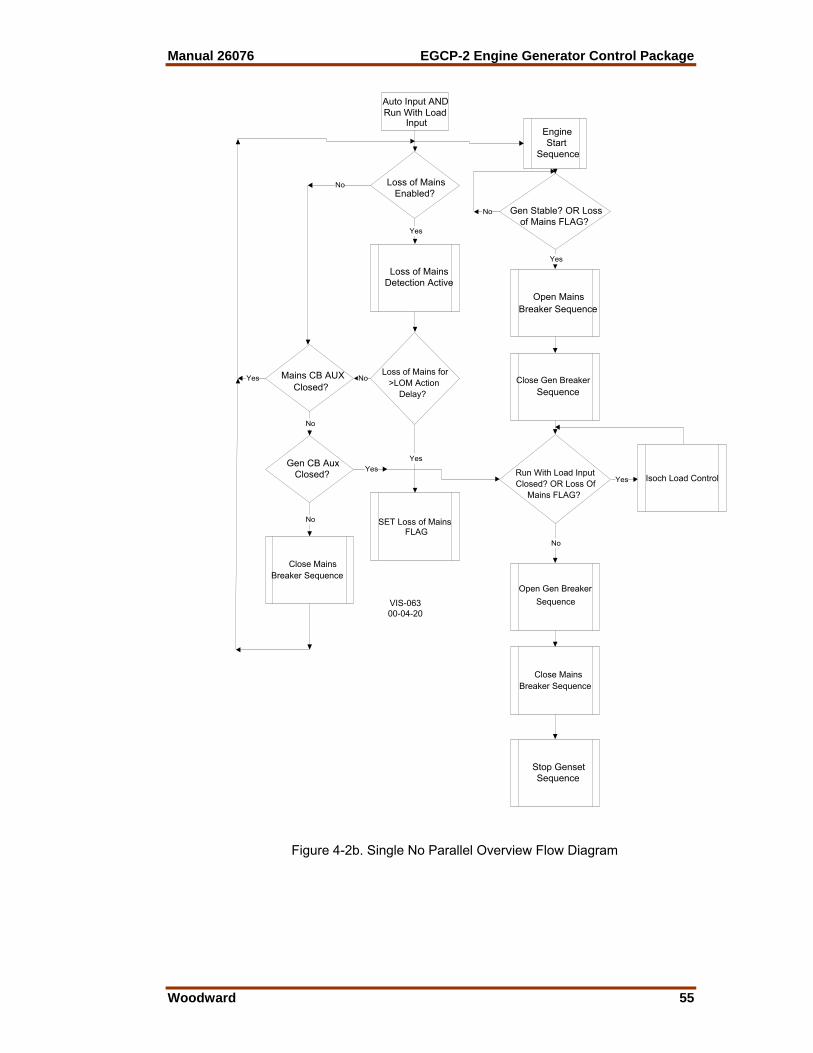
Manual 26076 EGCP-2 Engine Generator Control Package
Woodward 55
Auto Input ANDRun With Load
Input
Loss of MainsEnabled?
Loss of MainsDetection Active
Loss of Mains for>LOM Action
Delay?
Yes
Mains CB AUXClosed?
Close MainsBreaker Sequence
No
No
No
Yes
EngineStart
Sequence
Gen Stable? OR Lossof Mains FLAG?
Open MainsBreaker Sequence
Close Gen BreakerSequence
Run With Load InputClosed? OR Loss Of
Mains FLAG?
Yes
No
Close MainsBreaker Sequence
Stop GensetSequence
Open Gen BreakerSequence
Isoch Load Control
Gen CB AuxClosed?
No
YesYes
No
Yes
SET Loss of MainsFLAG
VIS-06300-04-20
Figure 4-2b. Single No Parallel Overview Flow Diagram

EGCP-2 Engine Generator Control Package Manual 26076
56 Woodward
LOAD
Switch Common
2
G52a
Process I/ENo Connection
Fault #6
Fault #1
3
Mains CB Aux
Gen CB Aux
Run W/LD
Voltage Raise
Voltage Lower
Speed Raise
Speed Lower1
1
NLT (No Load Test) or Manual
Mode of Load Transfer = No Parallel
Mode Selector Switch
Auto
Number of Units = Single
GENPTs
GENCTs
Test
Automatic
LocalPT
Connect
G52
Gen BreakerTrip
Single No Parallel Prime Power Application
AudibleAlarm
VisualAlarm
+Battery
+Battery
FuelSolenoid
EngineCrank
EnginePreglow
Mains BreakerTrip
Mains BreakerClose
+Battery
+Battery
+Battery
Visual Alarm
Audible Alarm
Preglow relay
Gen Breaker Trip Coil
Engine Crank Relay
Fuel shutoff solenoid
MainsPT Disconnect
Gen BreakerClose
BUSPT
+Battery
+Battery
2
31
Use fault #1 or #2 input if using aseperate device to sense Low OilPressure or High Water Temp.These Fault Inputs have 15 seconddelay timers on them after theengine reaches crank cutouttspeed.
Gen Breaker Close Coil -Battery
Only required if the speed and voltageneed to be adjusted when Testor Manual is selected.
See Switch Logic Diagram for Details
Manual
Manual
Manual
...
Faults #3 through #6 activate immediately,with programmable delays.
4
4 Manual mode requires manual generator breaker operation.Manual mode will operate in KW and Voltage Droop.
Application: Prime Power
No Mains Available (Prime Power Application)
No Connection
No Connection
No Connection
No Connection
crank
prglw
FUEL
GTC
GCC
VIS-06400-04-20
Figure 4-3. Single No Parallel Prime Power
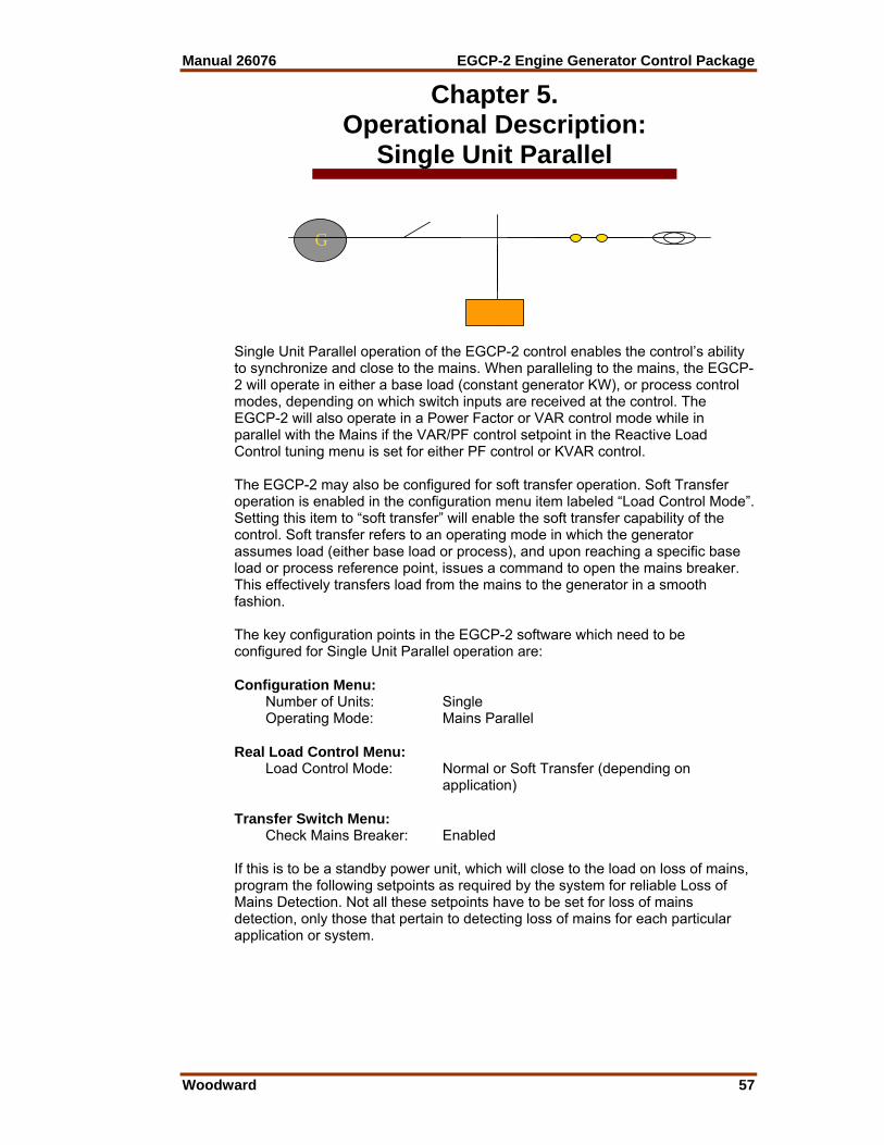
Manual 26076 EGCP-2 Engine Generator Control Package
Woodward 57
Chapter 5. Operational Description:
Single Unit Parallel
G
Single Unit Parallel operation of the EGCP-2 control enables the control’s ability to synchronize and close to the mains. When paralleling to the mains, the EGCP-2 will operate in either a base load (constant generator KW), or process control modes, depending on which switch inputs are received at the control. The EGCP-2 will also operate in a Power Factor or VAR control mode while in parallel with the Mains if the VAR/PF control setpoint in the Reactive Load Control tuning menu is set for either PF control or KVAR control. The EGCP-2 may also be configured for soft transfer operation. Soft Transfer operation is enabled in the configuration menu item labeled “Load Control Mode”. Setting this item to “soft transfer” will enable the soft transfer capability of the control. Soft transfer refers to an operating mode in which the generator assumes load (either base load or process), and upon reaching a specific base load or process reference point, issues a command to open the mains breaker. This effectively transfers load from the mains to the generator in a smooth fashion. The key configuration points in the EGCP-2 software which need to be configured for Single Unit Parallel operation are: Configuration Menu: Number of Units: Single Operating Mode: Mains Parallel Real Load Control Menu: Load Control Mode: Normal or Soft Transfer (depending on
application) Transfer Switch Menu: Check Mains Breaker: Enabled If this is to be a standby power unit, which will close to the load on loss of mains, program the following setpoints as required by the system for reliable Loss of Mains Detection. Not all these setpoints have to be set for loss of mains detection, only those that pertain to detecting loss of mains for each particular application or system.
EGCP-2 Engine Generator Control Package Manual 26076
58 Woodward
Transfer Switch Menu: Mains Under/Over Voltage Alarm: Loss of Mains Mains Under/Over Freq. Alarm: Loss of Mains Load Surge: Loss of Mains*
NOTE Loss of Mains may be substituted with Loss of Mains w/alarms if alarm indications during a loss of mains condition are desired. *Loss of Mains action is instant, and does not use the loss of mains action delay. All other Loss of Mains detection setpoints use the Loss of Mains action delay time before activating the generator set start sequence. Loss of mains action for a single parallel unit is identical to the single no parallel application. Upon sensing a loss of mains for the loss of mains action delay period, the EGCP-2 will open the mains breaker, start the generator set, wait for the gen stable time, and close the generator onto the dead bus, providing the load with power. Being a single unit parallel application, upon sensing return of the mains, and mains stable for the mains stable delay, the EGCP-2 will synchronize the generator set with the mains. After synchronizing to the mains, the EGCP-2 will parallel the generator with the mains, and softly unload the generator. Upon reaching the generator Unload Trip Point, the EGCP-2 will issue a generator breaker open command. This sequence softly transfers load from the generator back to the Mains. After the generator is unloaded, and its breaker is opened, it will shut down. There may be a cooldown period prior to shut down if the generator set has run at loads which exceed the Cooldown Limit KVA value. Switch Input Actions: Single Unit Parallel Auto Switch Enables LOM Detection. Run With Load Switch Starts Unit. Auto Switch must be closed for breaker operation. Test Switch When individually selected Starts Engine; no other action. Process Switch When individually selected No action. Auto and Run/Ld Synchronizes and Base Loads Unit with LOM detection enabled. Auto and Run/Ld and Process Synchronizes and Ramps to Process Control with LOM detection enabled.

Manual 26076 EGCP-2 Engine Generator Control Package
Woodward 59
Auto and Run with Load and Test Synchronizes and Ramps to Base Load. If “Load Control Mode” is set for Soft Transfer in configuration menu, unit
will open mains breaker when base load reference is reached. Auto and Run/Ld and Process and Test Synchronizes and Ramps to Process Control. Will open mains upon reaching Process Reference if software “Load Control
Mode” in configuration menu is set for Soft Transfer.
LOAD
Run With Load (closed transition)
Switch Common
2
G52a
Process I/E
Fault #6
Fault #13
Mains CB AuxGen CB Aux
Run W/LD
Voltage Raise
Voltage Lower
Speed Raise
Speed Lower1
1
GEN
NLT (No Load Test) or Manual
Mode of Load Transfer = Mains Parallel
Mode Selector Switch
Auto
Number of Units = Single
GENPTs
GENCTs
Test
Automatic
LocalPT
Connect
G52
Gen BreakerTrip GTC
FUEL
crank
Single Mains Parallel ApplicationPeak Shaving Unit
AudibleAlarm
VisualAlarm
+Battery
+Battery
FuelSolenoid
EngineCrank
EnginePreglow
Mains BreakerTrip
Mains BreakerClose
+Battery
+Battery
+Battery
Visual Alarm
Audible Alarm
Preglow relay
Gen Breaker Trip Coil
Engine Crank Relay
Fuel shutoff solenoid
prglw
GCC
MainsPT Disconnect
Gen BreakerClose
BUSPT
+Battery
+Battery
2
31
Use fault #1 or #2 input if using aseperate device to sense Low OilPressure or High Water Temp.These Fault Inputs have 15 seconddelay timers on them after theengine reaches crank cutouttspeed.
Gen Breaker Close Coil -Battery
Only required if the speed and voltageneed to be adjusted when Testor Manual is selected.
MAINS
See Switch Logic Diagram for Details
Manual
Manual
Manual
...
Faults #3 through #6 activate immediately,with programmable delays.
4
4 Manual mode requires manual mains and generator breaker operation.Manual mode will operate in KW and Voltage Droop.
Application: Peak Shaving Set
WattXducer
Process Input4-20mA or 1-5VDC5
5 Transducer input not requiredif Process Control Mode isNot used.
VIS-06501-03-30
MCC+Battery
Mains Breaker Close CoilManual
MTC+Battery
Mains Breaker Trip CoilManual
U52a
Figure 5-1. Single Unit Parallel Application

EGCP-2 Engine Generator Control Package Manual 26076
60 Woodward
Switch Based Logic (Single—Parallel)
TES
T
RU
N /w
LO
AD
A
UTO
P
RO
CE
SS
UTI
LITY
PO
WE
R
X X OFF 1 X X X STARTS ENGINE * X 1 X X STARTS ENGINE * 1 X 1 READY TO START ENGINE UPON LOSS OF UTILITY POWER
X 1 1 1 STARTS ENGINE / SYNCHRONIZES TO UTILITY / CONTROLS IN BASELOAD X 1 1 1 1 STARTS ENGINE / SYNCHRONIZES TO UTILITY / CONTROLS IN PROCESS 1 1 1 1 STARTS ENGINE / SYNCHS TO UTILITY / RAMPS TO BASELOAD / OPENS TB # 1 1 1 1 1 STARTS ENGINE / SYNCHS TO UTILITY / RAMPS TO PROCESS / OPENS TB # 1 X OPENS TB / STARTS ENGINE / CLOSES GB / CONTROLS IN ISOCH 1 X SYNCS TO UTILITY / OPENS GB / SHUTS DOWN ENGINE
* = When generator breaker is closed manually, unit will operate in Droop mode. # = Soft Transfer Setting must be "Enabled" 1 = Contact closed (Utility Power Stable) X = Contact open or closed (Utility Power Failed or Stable) TB = Utility Tie Breaker GB = Generator Breaker
= Transition from Utility Stable to Utility Failed = Transition from Utility Failed to Utility Stable
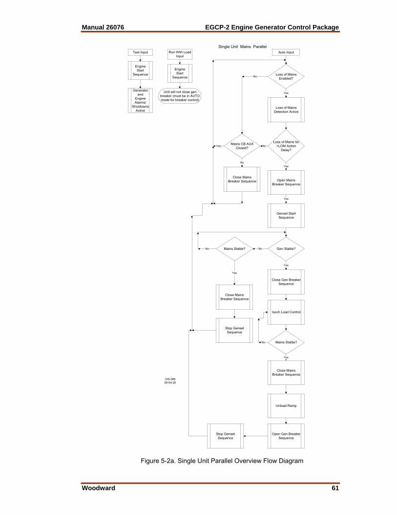
Manual 26076 EGCP-2 Engine Generator Control Package
Woodward 61
Single Unit Mains Parallel
Test Input Auto InputRun With LoadInput
EngineStart
Sequence
Generatorand
EngineAlarms/
ShutdownsActive
EngineStart
Sequence
Unit will not close genbreaker (must be in AUTOmode for breaker control)
Loss of MainsEnabled?
Loss of MainsDetection Active
Loss of Mains for>LOM Action
Delay?
Open MainsBreaker Sequence
Genset StartSequence
Gen Stable?Mains Stable?
Close Gen BreakerSequence
Isoch Load Control
Mains Stable?
Yes
Mains CB AUXClosed?
Close MainsBreaker Sequence
No
No
Yes
Yes
No
Yes
No
Yes
No
Yes
Close MainsBreaker Sequence
Stop GensetSequence
No
Yes
Close MainsBreaker Sequence
Stop GensetSequence
Open Gen BreakerSequence
Unload Ramp
VIS-06600-04-20
Figure 5-2a. Single Unit Parallel Overview Flow Diagram
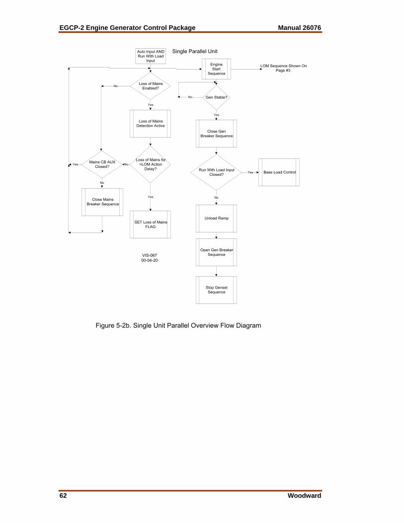
EGCP-2 Engine Generator Control Package Manual 26076
62 Woodward
Auto Input ANDRun With Load
Input
Loss of MainsEnabled?
Loss of MainsDetection Active
Loss of Mains for>LOM Action
Delay?
Yes
Mains CB AUXClosed?
Close MainsBreaker Sequence
No
No
No
Yes
EngineStart
Sequence
Gen Stable?
Close GenBreaker Sequence
Run With Load InputClosed? Yes
No
Open Gen BreakerSequence
Stop GensetSequence
Unload Ramp
Base Load Control
Yes
No
Yes
SET Loss of MainsFLAG
Single Parallel Unit
LOM Sequence Shown OnPage #3
VIS-06700-04-20
Figure 5-2b. Single Unit Parallel Overview Flow Diagram
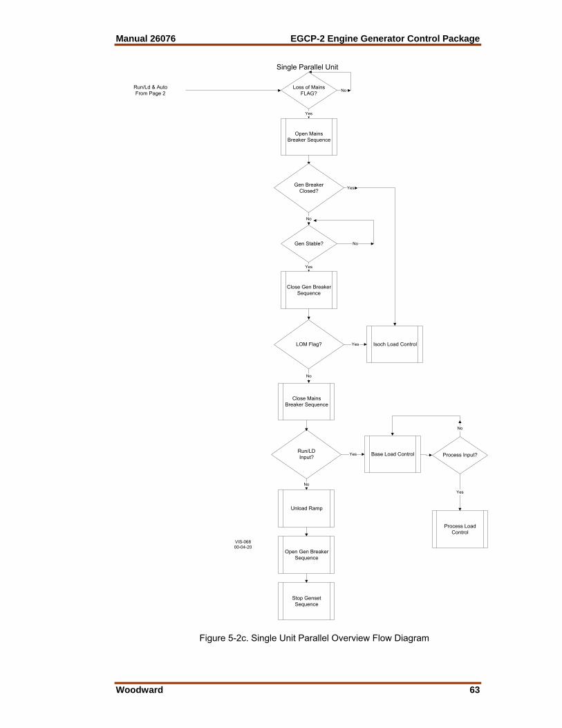
Manual 26076 EGCP-2 Engine Generator Control Package
Woodward 63
Close Gen BreakerSequence
Loss of MainsFLAG? No
Yes
Gen Stable?
Open MainsBreaker Sequence
LOM Flag? Yes Isoch Load Control
Gen BreakerClosed?
No
Close MainsBreaker Sequence
Run/LDInput?
Yes Base Load Control
Unload Ramp
Open Gen BreakerSequence
Stop GensetSequence
No
Yes
No
No
Yes
Process Input?
Yes
Process LoadControl
No
Single Parallel Unit
Run/Ld & AutoFrom Page 2
VIS-06800-04-20
Figure 5-2c. Single Unit Parallel Overview Flow Diagram

EGCP-2 Engine Generator Control Package Manual 26076
64 Woodward
Chapter 6. Operating Mode:
Multiple No Parallel
G
G
G
Multiple no parallel operation combines the generating capacity of multiple units to supply an isolated load. All operations of the generators on load in a multiple no parallel system are accomplished isolated from the mains. In a multiple unit system the EGCP-2 control operates in a Master/Slave type configuration. The master role is determined over the inter-control RS-485 network by the unit in Auto mode with the highest network priority (lowest numerical value). All other units on the same network, and in Auto mode are considered slave units, and follow the master commands for starting, and stopping. The Sequencing Status Screen can be viewed on any unit in auto to determine the master control on the network. The key configuration points in the EGCP-2 software which need to be configured for Multiple Unit No Parallel operation are: Configuration Menu: Number of Units: Multiple Operating Mode: No Parallel Real Load Control Menu: Load Control Mode: Normal Transfer Switch Menu: Check Mains Breaker: Enabled at units receiving Mains Breaker Aux. hard wired input in standby. Disabled if prime power application (there is no mains breaker to monitor).

Manual 26076 EGCP-2 Engine Generator Control Package
Woodward 65
IMPORTANT When operating as standby units there must be at least one unit on the network and in Auto with the mains breaker aux input wired, and the Check Mains Breaker setpoint Enabled at any given time. If these are to be standby power units, which will close to the load on loss of mains, program the following setpoints as required by the system for reliable Loss of Mains Detection. Not all these setpoints have to be set for loss of mains detection, only those that pertain to detecting loss of mains for each particular application or system. If these are to be a prime power units, which operate without any mains input to the load, program all units in the system for either Mains Frequency Low Limit Alarm, or Mains Voltage Low Limit Alarm for Loss Of Mains. This allows each unit to start any time it is given an auto input. In a multiple no parallel system automatic sequencing will be effective between all units in the auto mode with the “Automatic Sequencing” setpoint in the configuration menu set for “enabled”. If this setpoint is set for disabled, that unit will not be a part of the auto sequencing scheme. Transfer Switch Menu: Mains Under/Over Voltage Alarm: Loss of Mains Mains Under/Over Freq. Alarm: Loss of Mains
NOTE Loss of Mains may be substituted with Loss of Mains w/alarms if alarm indications during a loss of mains condition are desired. Switch Input Actions: Multiple No Parallel Auto Switch Enables LOM detection. Enables Automatic Sequencing. Enables Dead Bus Closing. Run with Load Switch Starts Unit, but without Auto switch unit cannot close to dead bus. Process Switch When individually selected No effect in this mode. Test Switch When individually selected Starts Engine; no further action. Auto and Run with Load Isolates Mains. Loads Generators which are operating in Auto Mode (Enables Dead Bus
Closing). Removal of Run with Load input causes open transition back to mains (so
long as mains are in spec).

EGCP-2 Engine Generator Control Package Manual 26076
66 Woodward
LOAD
Run With Load (closed transition)
Switch Common
2
G52a
U52a
Process I/ENo Connection
Fault #6
Fault #1
3
Mains CB Aux
Gen CB Aux
Run W/LD
Voltage Raise
Voltage Lower
Speed Raise
Speed Lower1
1
GEN
NLT (No Load Test) or Manual
Mode of Load Transfer = No Parallel
Mode Selector Switch
Auto
Number of Units =Multiple
GENPTs
GENCTs
Test
Automatic
LocalPT
Connect
G52
Gen BreakerTrip GTC
FUEL
crank
MCC
Multiple No Parallel Application
AudibleAlarm
VisualAlarm
+Battery
+Battery
FuelSolenoid
EngineCrank
EnginePreglow
Mains BreakerTrip
Mains BreakerClose
+Battery
+Battery
+Battery
+Battery
+Battery
Visual Alarm
Audible Alarm
Mains Breaker Trip Coil
Preglow relay
Gen Breaker Trip Coil
Engine Crank Relay
Fuel shutoff solenoid
prglw
MTC
Mains Breaker Close Coil
GCC
MainsPT Disconnect
Gen BreakerClose
BUSPT
+Battery
+Battery
2
3
U52
1
Use fault #1 or #2 input if using aseperate device to sense Low OilPressure or High Water Temp.These Fault Inputs have 15 seconddelay timers on them after theengine reaches crank cutouttspeed.
Gen Breaker Close Coil -Battery
Only required if the speed and voltageneed to be adjusted when Testor Manual is selected.
MAINS
See Switch Logic Diagram for Details
Manual
Manual
Manual
Manual
Manual
..
.
Faults #3 through #6 activate immediately, with programmable delays.
4
4 Manual mode requires manual mains and generator breaker operation.Manual mode will operate in KW and Voltage Droop.
Application: Standby Power
RS-485 LONTo other Units
4
4
4
4
Only required if "Check Mains Breaker" setpointis Enabled. Any unit which may operate as the mastermust have these inputs.
VIS-06900-04-20
Figure 6-1. Multiple Unit No Parallel Application

Manual 26076 EGCP-2 Engine Generator Control Package
Woodward 67
Switch Based Logic (Multiple—No Parallel, Master Control’s Action)
TES
T
RU
N /w
LO
AD
A
UTO
PR
OC
ES
S
UTI
LITY
PO
WE
R
X X OFF 1 X X X STARTS MASTER ENGINE * X 1 X X STARTS MASTER ENGINE * 1 X 1 READY TO START ALL ENGINES UPON LOSS OF UTILITY POWER
X 1 1 X 1 OPENS TB / STARTS ALL ENGINES / CLOSES GB / CONTROLS IN ISOCH # 1 X OPENS TB / STARTS ALL ENGINES / CLOSES GB / CONTROLS IN ISOCH # 1 X OPENS ALL UNIT GBs / CLOSES TB / SHUTS DOWN ALL UNITS
* = When generator breaker is closed manually, unit will operate in Droop mode. # = Depending on plant load, slave units will be sequenced on or off the plant bus. 1 = Contact closed (Utility Power OK) X = Contact open or closed (Utility Power Failed or OK) TB = Utility Tie Breaker GB = Generator Breaker
= Transition from Utility Stable to Utility Failed = Transition from Utility Failed to Utility Stable
Switch Based Logic (Multiple—No Parallel, Slave Control’s Action)
TES
T R
UN
/w L
OA
D
AU
TO
PR
OC
ES
S
X OFF 1 X X STARTS ENGINE * X 1 X STARTS ENGINE * 1 X FOLLOWS ALL MASTER'S COMMANDS
* = When generator breaker is closed manually, unit will operate in Droop mode 1 = Contact closed X = Contact open or closed

EGCP-2 Engine Generator Control Package Manual 26076
68 Woodward
MASTER Multiple Unit No Parallel
Test Input Auto InputRun With LoadInput
EngineStart
SequenceEngineStart
SequenceLoss of Mains
Enabled?
Loss of MainsDetection Active
Loss of Mains for>LOM Action
Delay?
Open MainsBreaker Sequence
Genset StartSequence
Gen Stable?Mains Stable?
Close Gen BreakerSequence
Isoch Load Controland Sequencing
Mains Stable?
Yes
Mains CB AUXClosed?
Close MainsBreaker Sequence
No
No
Yes
No
Yes
No
Yes
No
Yes
Close MainsBreaker Sequence
Stop GensetSequence
No
Yes
Close MainsBreaker Sequence
Stop GensetSequence
Open Gen BreakerSequence
Unit will not performauto reclose if mains
breaker opens
Unit will not performauto reclose if mains
breaker opens
Set System RUNwith LOAD FLAG
Remove SystemRUN with LOAD
FLAG
Remove SystemRUN with LOAD
FLAG
Page 1
VIS-07000-04-20
Figure 6-2a. Master Multiple Unit No Parallel Overview Flow Diagram

Manual 26076 EGCP-2 Engine Generator Control Package
Woodward 69
Auto Input ANDRun With Load
Input
Loss of MainsEnabled?
Loss of MainsDetection Active
Loss of Mains for>LOM Action
Delay?
Yes
Mains CB AUXClosed?
Close MainsBreaker Sequence
No
No
No
Yes
EngineStart
Sequence
Gen Stable? OR Loss ofMains FLAG?
Open MainsBreaker Sequence
Close Gen BreakerSequence
Run With Load InputClosed? OR Loss Of
Mains FLAG?Yes
No
Close MainsBreaker Sequence
Stop GensetSequence
Open Gen BreakerSequence
Isoch Load Controlwith Sequencing
Gen CB AuxClosed?
No
Yes
Yes
No
Yes
SET Loss of MainsFLAG
Loss of MainsFLAG?
No
Yes Gen Stable?
Yes
No
MASTER Multiple Unit No Mains Parallel
Set SystemRUN with
LOADFLAG
Remove SystemRUN with LOAD
FLAG
Page 2
VIS-07100-04-20
Figure 6-2b. Master Multiple Unit No Parallel Overview Flow Diagram
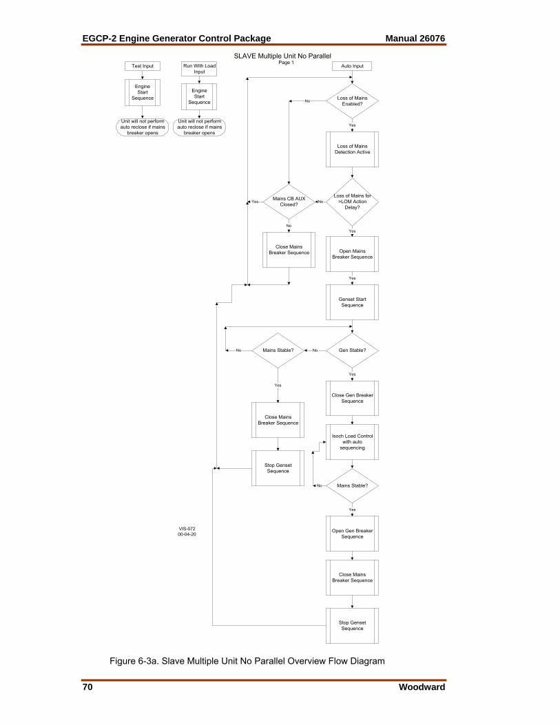
EGCP-2 Engine Generator Control Package Manual 26076
70 Woodward
SLAVE Multiple Unit No ParallelTest Input Auto InputRun With Load
Input
EngineStart
SequenceEngineStart
SequenceLoss of Mains
Enabled?
Loss of MainsDetection Active
Loss of Mains for>LOM Action
Delay?
Open MainsBreaker Sequence
Genset StartSequence
Gen Stable?Mains Stable?
Close Gen BreakerSequence
Isoch Load Controlwith auto
sequencing
Mains Stable?
Yes
Mains CB AUXClosed?
Close MainsBreaker Sequence
No
No
Yes
Yes
No
Yes
No
Yes
No
Yes
Close MainsBreaker Sequence
Stop GensetSequence
No
Yes
Close MainsBreaker Sequence
Stop GensetSequence
Open Gen BreakerSequence
Unit will not performauto reclose if mains
breaker opens
Unit will not performauto reclose if mains
breaker opens
Page 1
VIS-07200-04-20
Figure 6-3a. Slave Multiple Unit No Parallel Overview Flow Diagram

Manual 26076 EGCP-2 Engine Generator Control Package
Woodward 71
Auto Input ANDRun With Load
Input
Loss of MainsEnabled?
Loss of MainsDetection Active
Loss of Mains for>LOM Action
Delay?
Yes
Mains CB AUXClosed?
Close MainsBreaker Sequence
No
No
No
Yes
EngineStart
Sequence
Gen Stable? OR Loss ofMains FLAG?
Open MainsBreaker Sequence
Close Gen BreakerSequence
Run With Load InputClosed? OR Loss Of
Mains FLAG?Yes
No
Close MainsBreaker Sequence
Stop GensetSequence
Open Gen BreakerSequence
Isoch Load Control
Gen CB AuxClosed?
No
Yes
Yes
No
Yes
SET Loss of MainsFLAG
Loss of MainsFLAG?
No
Yes Gen Stable?
Yes
No
SLAVE Multiple Unit No ParallelPage 2
VIS-07300-04-20
Figure 6-3b. Slave Multiple Unit No Parallel Overview Flow Diagram
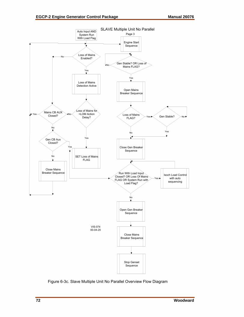
EGCP-2 Engine Generator Control Package Manual 26076
72 Woodward
Auto Input ANDSystem Run
With Load Flag
Loss of MainsEnabled?
Loss of MainsDetection Active
Loss of Mains for>LOM Action
Delay?
Yes
Mains CB AUXClosed?
Close MainsBreaker Sequence
No
No
No
Yes
Engine StartSequence
Gen Stable? OR Loss ofMains FLAG?
Open MainsBreaker Sequence
Close Gen BreakerSequence
Run With Load InputClosed? OR Loss Of MainsFLAG OR System Run with
Load Flag?
Yes
No
Close MainsBreaker Sequence
Stop GensetSequence
Open Gen BreakerSequence
Isoch Load Controlwith auto
sequencing
Gen CB AuxClosed?
No
Yes
Yes
No
Yes
SET Loss of MainsFLAG
Loss of MainsFLAG?
No
Yes Gen Stable?
Yes
No
SLAVE Multiple Unit No ParallelPage 3
VIS-07400-04-20
Figure 6-3c. Slave Multiple Unit No Parallel Overview Flow Diagram
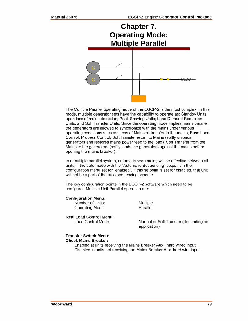
Manual 26076 EGCP-2 Engine Generator Control Package
Woodward 73
Chapter 7. Operating Mode: Multiple Parallel
G
G
G
The Multiple Parallel operating mode of the EGCP-2 is the most complex. In this mode, multiple generator sets have the capability to operate as: Standby Units upon loss of mains detection; Peak Shaving Units; Load Demand Reduction Units, and Soft Transfer Units. Since the operating mode implies mains parallel, the generators are allowed to synchronize with the mains under various operating conditions such as: Loss of Mains re-transfer to the mains, Base Load Control, Process Control, Soft Transfer return to Mains (softly unloads generators and restores mains power feed to the load), Soft Transfer from the Mains to the generators (softly loads the generators against the mains before opening the mains breaker). In a multiple parallel system, automatic sequencing will be effective between all units in the auto mode with the “Automatic Sequencing” setpoint in the configuration menu set for “enabled”. If this setpoint is set for disabled, that unit will not be a part of the auto sequencing scheme. The key configuration points in the EGCP-2 software which need to be configured Multiple Unit Parallel operation are: Configuration Menu: Number of Units: Multiple Operating Mode: Parallel Real Load Control Menu: Load Control Mode: Normal or Soft Transfer (depending on
application) Transfer Switch Menu: Check Mains Breaker: Enabled at units receiving the Mains Breaker Aux . hard wired input. Disabled in units not receiving the Mains Breaker Aux. hard wire input.

EGCP-2 Engine Generator Control Package Manual 26076
74 Woodward
IMPORTANT There must be at least one unit on the network and in Auto with the mains breaker aux hard wired input, and configured for “Check Mains Breaker” setpoint “enabled” at any given time. If these are to be standby power units, which will close to the load on loss of mains, program the following setpoints as required by the system for reliable Loss of Mains Detection. Not all these setpoints have to be set for loss of mains detection, only those that pertain to detecting loss of mains for each particular application or system. Transfer Switch Menu: Mains Under/Over Voltage Alarm: Loss of Mains Mains Under/Over Freq. Alarm: Loss of Mains
NOTE Loss of Mains may be substituted with Loss of Mains w/alarms if alarm indications during a loss of mains condition are desired. Switch Input Actions: Multiple Parallel Auto Enables LOM Detection and Dead Bus Closing. Enables Auto Sequencing. Run With Load StartsUnit. Auto Switch must be closed for breaker operation. Process When individually selected No action as a single input. Test When individually selected Starts Engine. Auto and Run With Load and Test (Base load Soft Transfer Mode Selected) Starts all Units in Auto Mode. Units synchronize and parallel with Mains. Units Ramp to Base Load control Reference. Upon reaching Base Load Reference, Master opens Mains Breaker. Removing Run with Load input softly transfers load back to mains. Auto and Run With Load and Process and Test (Process Soft Transfer Mode Selected) Starts all Units in Auto Mode. Units synchronize and parallel with Mains. Units Ramp to Process control Reference. Upon reaching Process Reference, Master opens Mains Breaker. Removing Run with Load input softly transfers load back to mains.

Manual 26076 EGCP-2 Engine Generator Control Package
Woodward 75
LOAD
Switch Common
2
G52a
Process I/ENo Connection
Fault #6
Fault #1
3
Mains CB Aux
Gen CB Aux
Run W/LD
Voltage Raise
Voltage Lower
Speed Raise
Speed Lower1
GEN
NLT (No Load Test) or Manual
Mode of Load Transfer = No Parallel
Mode Selector Switch
Auto
Number of Units = Multiple
GENPTs
GENCTs
Test
Automatic
LocalPT
Connect
G52
Gen BreakerTrip GTC
FUEL
crank
Multiple No Parallel Prime Power Application
AudibleAlarm
VisualAlarm
+Battery
+Battery
FuelSolenoid
EngineCrank
EnginePreglow
Mains BreakerTrip
Mains BreakerClose
+Battery
+Battery
+Battery
Visual Alarm
Audible Alarm
Preglow relay
Gen Breaker Trip Coil
Engine Crank Relay
Fuel shutoff solenoid
prglw
GCC
MainsPT Disconnect
Gen BreakerClose
BUSPT
+Battery
+Battery
2
31
Use fault #1 or #2 input if using aseperate device to sense Low OilPressure or High Water Temp.These Fault Inputs have 15 seconddelay timers on them after theengine reaches crank cutouttspeed.
Gen Breaker Close Coil -Battery
Only required if the speed and voltageneed to be adjusted when Testor Manual is selected.
See Switch Logic Diagram for Details
Manual
Manual
Manual
..
.
Faults #3 through #6 activate immediately, with programmable delays.
4
4 Manual mode requires manual generator breaker operation.Manual mode will operate in KW and Voltage Droop.
Application: Prime Power
No Mains Available (Prime Power Application)
No Connection
No Connection
No Connection
Run With Load
RS-485 LONTo other Units
VIS-07500-04-20
Figure 7-1. Multiple Unit No Parallel Prime Power Application
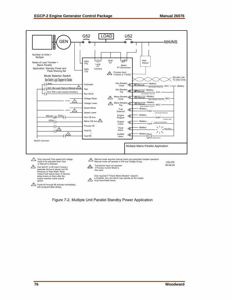
EGCP-2 Engine Generator Control Package Manual 26076
76 Woodward
LOAD
Run With Load (closed transition)
Switch Common
2
G52a
U52a
Process I/E
Fault #6
Fault #1
3
Mains CB Aux
Gen CB Aux
Run W/LD
Voltage Raise
Voltage Lower
Speed Raise
Speed Lower1
1
GEN
NLT (No Load Test) or Manual
Mode of Load Transfer = Mains Parallel
Mode Selector Switch
Auto
Number of Units = Multiple
GENPTs
GENCTs
Test
Automatic
LocalPT
Connect
G52
Gen BreakerTrip GTC
FUEL
crank
MCC
Multiple Mains Parallel Application
AudibleAlarm
VisualAlarm
+Battery
+Battery
FuelSolenoid
EngineCrank
EnginePreglow
Mains BreakerTrip
Mains BreakerClose
+Battery
+Battery
+Battery
+Battery
+Battery
Visual Alarm
Audible Alarm
Mains Breaker Trip Coil
Preglow relay
Gen Breaker Trip Coil
Engine Crank Relay
Fuel shutoff solenoid
prglw
MTC
Mains Breaker Close Coil
GCC
MainsPT Disconnect
Gen BreakerClose
BUSPT
+Battery
+Battery
2
3
U52
1
Use fault #1 or #2 input if using aseperate device to sense Low OilPressure or High Water Temp.These Fault Inputs have 15 seconddelay timers on them after theengine reaches crank cutouttspeed.
Gen Breaker Close Coil -Battery
Only required if the speed and voltageneed to be adjusted when Testor Manual is selected.
MAINS
See Switch Logic Diagram for Details
Manual
Manual
Manual
Manual
Manual
..
.
Faults #3 through #6 activate immediately, with programmable delays.
4
4 Manual mode requires manual mains and generator breaker operation.Manual mode will operate in KW and Voltage Droop.
Application: Standby Power and Peak Shaving Set
WattXducer
Process Input4-20mA or 1-5VDC5
5 Transducer input not requiredif Process Control Mode is Not used.
RS-485 LONTo other Units
6
Only required if "Check Mains Breaker" setpointis Enabled. Any unit which may operate as the mastermust have these inputs.
6
6
6
VIS-07600-04-20
Figure 7-2. Multiple Unit Parallel Standby Power Application
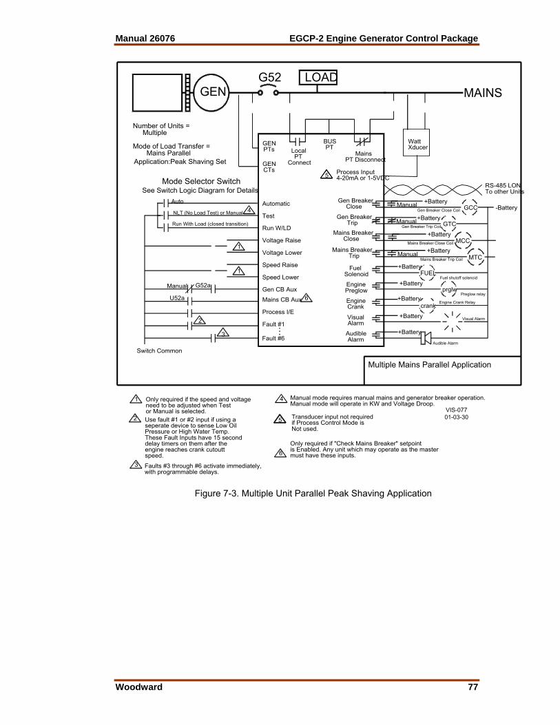
Manual 26076 EGCP-2 Engine Generator Control Package
Woodward 77
LOAD
Run With Load (closed transition)
Switch Common
2
G52a
U52a
Process I/E
Fault #6
Fault #13
Mains CB Aux
Gen CB Aux
Run W/LD
Voltage Raise
Voltage Lower
Speed Raise
Speed Lower1
1
GEN
NLT (No Load Test) or Manual
Mode of Load Transfer = Mains Parallel
Mode Selector Switch
Auto
Number of Units = Multiple
GENPTs
GENCTs
Test
Automatic
LocalPT
Connect
G52
Gen BreakerTrip GTC
FUEL
crank
Multiple Mains Parallel Application
AudibleAlarm
VisualAlarm
+Battery
+Battery
FuelSolenoid
EngineCrank
EnginePreglow
Mains BreakerTrip
Mains BreakerClose
+Battery
+Battery
+Battery
Visual Alarm
Audible Alarm
Preglow relay
Gen Breaker Trip Coil
Engine Crank Relay
Fuel shutoff solenoid
prglw
GCC
MainsPT Disconnect
Gen BreakerClose
BUSPT
+Battery
+Battery
2
3
1
Use fault #1 or #2 input if using aseperate device to sense Low OilPressure or High Water Temp.These Fault Inputs have 15 seconddelay timers on them after theengine reaches crank cutouttspeed.
Gen Breaker Close Coil -Battery
Only required if the speed and voltageneed to be adjusted when Testor Manual is selected.
MAINS
See Switch Logic Diagram for Details
Manual
Manual
Manual
...
Faults #3 through #6 activate immediately,with programmable delays.
4
4 Manual mode requires manual mains and generator breaker operation.Manual mode will operate in KW and Voltage Droop.
Application:Peak Shaving Set
WattXducer
Process Input4-20mA or 1-5VDC5
5 Transducer input not requiredif Process Control Mode isNot used.
RS-485 LONTo other Units
6
6Only required if "Check Mains Breaker" setpointis Enabled. Any unit which may operate as the mastermust have these inputs.
VIS-07701-03-30
MCC+Battery
Mains Breaker Close Coil
MTC+Battery
Mains Breaker Trip CoilManual
Figure 7-3. Multiple Unit Parallel Peak Shaving Application
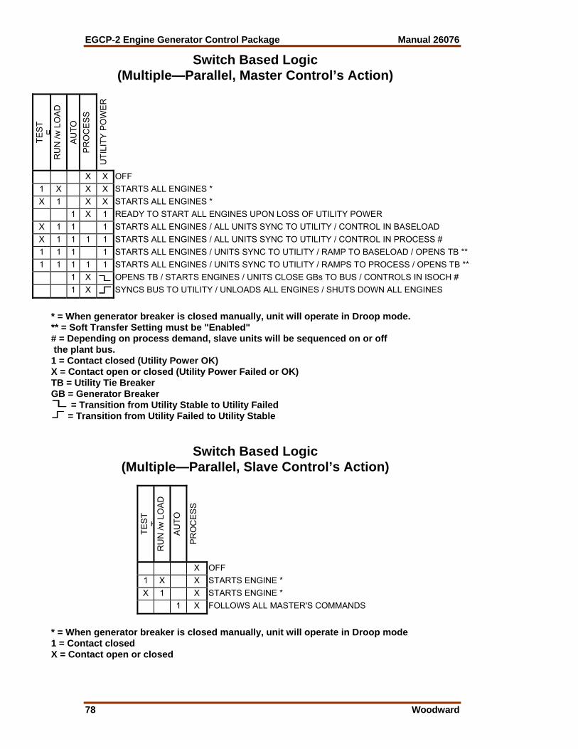
EGCP-2 Engine Generator Control Package Manual 26076
78 Woodward
Switch Based Logic (Multiple—Parallel, Master Control’s Action)
TES
T E
RU
N /w
LO
AD
AU
TO
PR
OC
ES
S
UTI
LITY
PO
WE
R
X X OFF 1 X X X STARTS ALL ENGINES * X 1 X X STARTS ALL ENGINES * 1 X 1 READY TO START ALL ENGINES UPON LOSS OF UTILITY POWER
X 1 1 1 STARTS ALL ENGINES / ALL UNITS SYNC TO UTILITY / CONTROL IN BASELOAD X 1 1 1 1 STARTS ALL ENGINES / ALL UNITS SYNC TO UTILITY / CONTROL IN PROCESS # 1 1 1 1 STARTS ALL ENGINES / UNITS SYNC TO UTILITY / RAMP TO BASELOAD / OPENS TB ** 1 1 1 1 1 STARTS ALL ENGINES / UNITS SYNC TO UTILITY / RAMPS TO PROCESS / OPENS TB ** 1 X OPENS TB / STARTS ENGINES / UNITS CLOSE GBs TO BUS / CONTROLS IN ISOCH # 1 X SYNCS BUS TO UTILITY / UNLOADS ALL ENGINES / SHUTS DOWN ALL ENGINES
* = When generator breaker is closed manually, unit will operate in Droop mode. ** = Soft Transfer Setting must be "Enabled" # = Depending on process demand, slave units will be sequenced on or off the plant bus. 1 = Contact closed (Utility Power OK) X = Contact open or closed (Utility Power Failed or OK) TB = Utility Tie Breaker GB = Generator Breaker
= Transition from Utility Stable to Utility Failed = Transition from Utility Failed to Utility Stable
Switch Based Logic (Multiple—Parallel, Slave Control’s Action)
TES
T T
RU
N /w
LO
AD
AU
TO
PR
OC
ES
S
X OFF 1 X X STARTS ENGINE * X 1 X STARTS ENGINE * 1 X FOLLOWS ALL MASTER'S COMMANDS
* = When generator breaker is closed manually, unit will operate in Droop mode 1 = Contact closed X = Contact open or closed

Manual 26076 EGCP-2 Engine Generator Control Package
Woodward 79
Test Input Auto InputRun With LoadInput
EngineStart
Sequence
Generatorand
EngineAlarms/
ShutdownsActive
EngineStart
Sequence
Unit will not close genbreaker (must be in AUTOmode for breaker control)
Loss of MainsEnabled?
Loss of MainsDetection Active
Loss of Mains for>LOM Action
Delay?
Open MainsBreaker Sequence
Set System RUNwith Load Flag and
Genset StartSequence
Gen Stable?Mains Stable?
Close Gen BreakerSequence
Isoch Load Controlwith sequencing
Mains Stable?
Yes
Mains CB AUXClosed?
Mains BreakerReclose Sequence
No
No
Yes
Yes
No
Yes
No
Yes
No
Yes
Close MainsBreaker Sequence
Remove SystemRun with Load Flagand Stop Genset
Sequence
No
Yes
Close MainsBreaker Sequence
Stop GensetSequence
Open Gen BreakerSequence
Remove SystemRun with Load Flag
andUnload Ramp
MASTER Multiple Unit Utility ParallelPage 1
VIS-07800-04-20
Figure 7-4a. Master Multiple Parallel Process Control Flow Diagram

EGCP-2 Engine Generator Control Package Manual 26076
80 Woodward
Auto Input ANDRun With Load
Input
Loss of MainsEnabled?
Loss of MainsDetection Active
Loss of Mains for>LOM Action
Delay?
Yes
Mains CB AUXClosed?
Mains BreakerReclose Sequence
No
No
No
Yes
Set System Run withLoad Flag andEngine StartSequence
Gen Stable?
Close GenBreaker Sequence
Run With Load InputClosed?
Yes
No
Open Gen BreakerSequence
Stop GensetSequence
Remove SystemRun with Load Flag
andUnload Ramp
Base Load Control
Yes
No
Yes
SET Loss of MainsFLAG
LOM Sequence Shown OnPage #3
MASTER Multiple Unit Utility ParallelPage 2
VIS-07900-04-20
Figure 7-4b. Master Multiple Parallel Process Control Flow Diagram
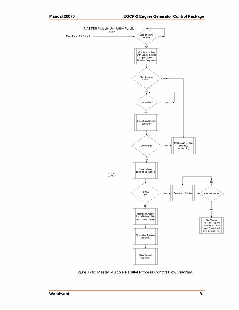
Manual 26076 EGCP-2 Engine Generator Control Package
Woodward 81
Close Gen BreakerSequence
Loss of MainsFLAG?
No
Yes
Gen Stable?
Set System Runwith Load Flag and
Open MainsBreaker Sequence
LOM Flag? YesIsoch Load Control
and autosequencing
Gen BreakerClosed?
No
Close MainsBreaker Sequence
Run/LDInput? Yes Base Load Control
Remove SystemRun with Load Flagand Unload Ramp
Open Gen BreakerSequence
Stop GensetSequence
No
Yes
No
No
Yes
Process Input?
Yes
Set MasterProcess Flag andSystem ProcessLoad Control withauto sequencing.
No
From Pages 2,4,5 and 7
MASTER Multiple Unit Utility ParallelPage 3
VIS-08000-04-24
Figure 7-4c. Master Multiple Parallel Process Control Flow Diagram

EGCP-2 Engine Generator Control Package Manual 26076
82 Woodward
Auto Input ANDRun With Load
Input ANDProcess
Loss of MainsEnabled?
Loss of MainsDetection Active
Loss of Mains for>LOM Action
Delay?
Yes
Mains CB AUXClosed?
Mains BreakerReclose Sequence
No
No
No
Yes
Set System Run withLoad Flag andEngine StartSequence
Gen Stable?
Close GenBreaker Sequence
Run With Load InputClosed? Yes
No
Open Gen BreakerSequence
Stop GensetSequence
Remove systemrun with load flagand Unload Ramp
Base Load Control
Yes
No
Yes
SET Loss of MainsFLAG
LOM Sequence Shown OnPage #3
Process InputClosed?
No
Yes
Set SystemProcess Flag andSystem ProcessLoad Control withauto sequencing
MASTER Multiple Unit Utility ParallelPage 4
VIS-08100-04-24
Figure 7-4d. Master Multiple Parallel Process Control Flow Diagram
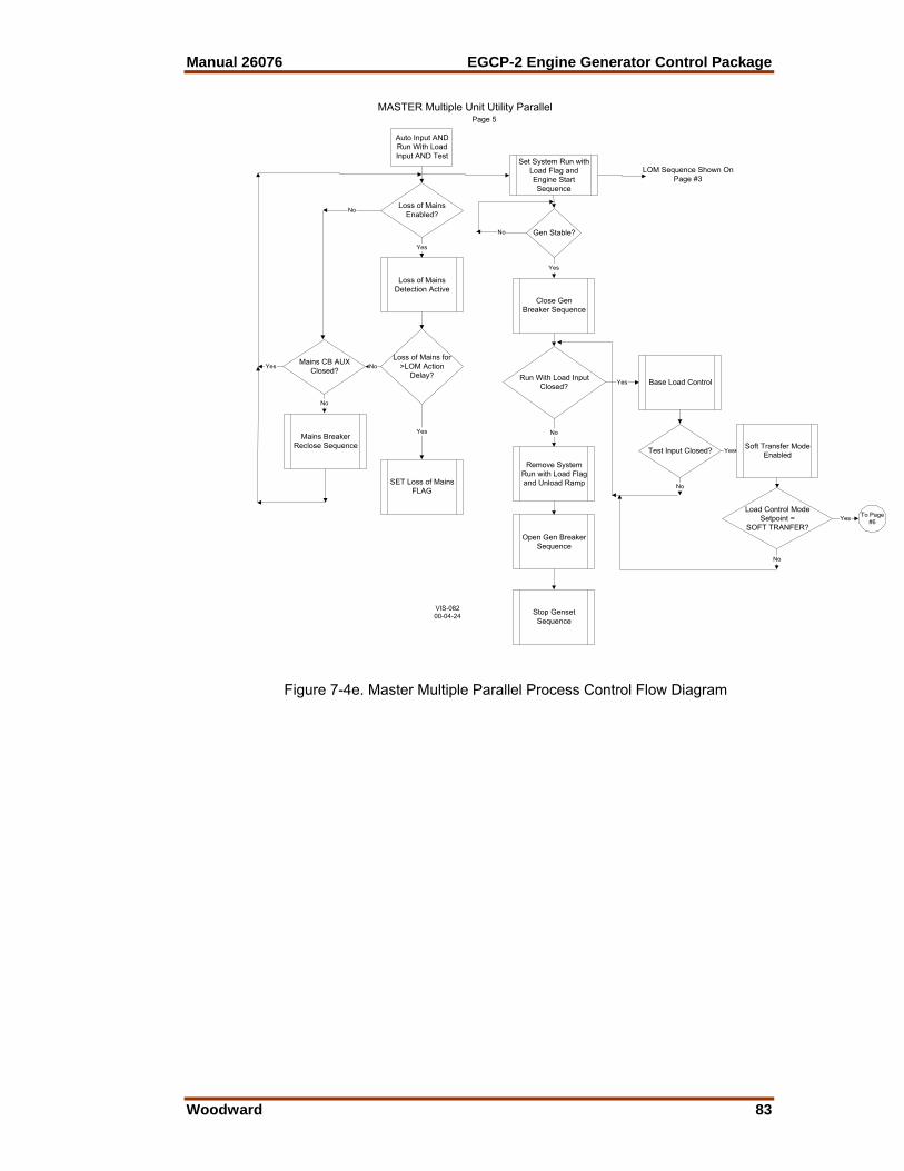
Manual 26076 EGCP-2 Engine Generator Control Package
Woodward 83
Auto Input ANDRun With LoadInput AND Test
Loss of MainsEnabled?
Loss of MainsDetection Active
Loss of Mains for>LOM Action
Delay?
Yes
Mains CB AUXClosed?
Mains BreakerReclose Sequence
No
No
No
Yes
Set System Run withLoad Flag andEngine StartSequence
Gen Stable?
Close GenBreaker Sequence
Run With Load InputClosed? Yes
No
Open Gen BreakerSequence
Stop GensetSequence
Remove SystemRun with Load Flagand Unload Ramp
Base Load Control
Yes
No
Yes
SET Loss of MainsFLAG
LOM Sequence Shown OnPage #3
Test Input Closed?
No
YesSoft Transfer Mode
Enabled
Load Control ModeSetpoint =
SOFT TRANFER?
No
Yes To Page#6
MASTER Multiple Unit Utility ParallelPage 5
VIS-08200-04-24
Figure 7-4e. Master Multiple Parallel Process Control Flow Diagram
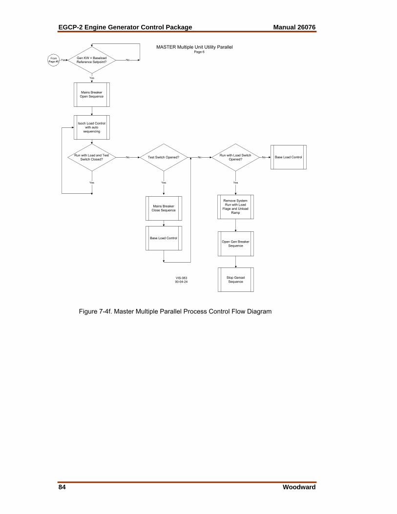
EGCP-2 Engine Generator Control Package Manual 26076
84 Woodward
Yes Gen KW = BaseloadReference Setpoint?
Yes
No
Mains BreakerOpen Sequence
Isoch Load Controlwith auto
sequencing
Run with Load and TestSwitch Closed?
No
Yes
Test Switch Opened? No
Yes
Mains BreakerClose Sequence
Base Load Control
Run with Load SwitchOpened?
No Base Load Control
Yes
Remove SystemRun with Load
Flage and UnloadRamp
Open Gen BreakerSequence
Stop GensetSequence
FromPage #5
MASTER Multiple Unit Utility ParallelPage 6
VIS-08300-04-24
Figure 7-4f. Master Multiple Parallel Process Control Flow Diagram
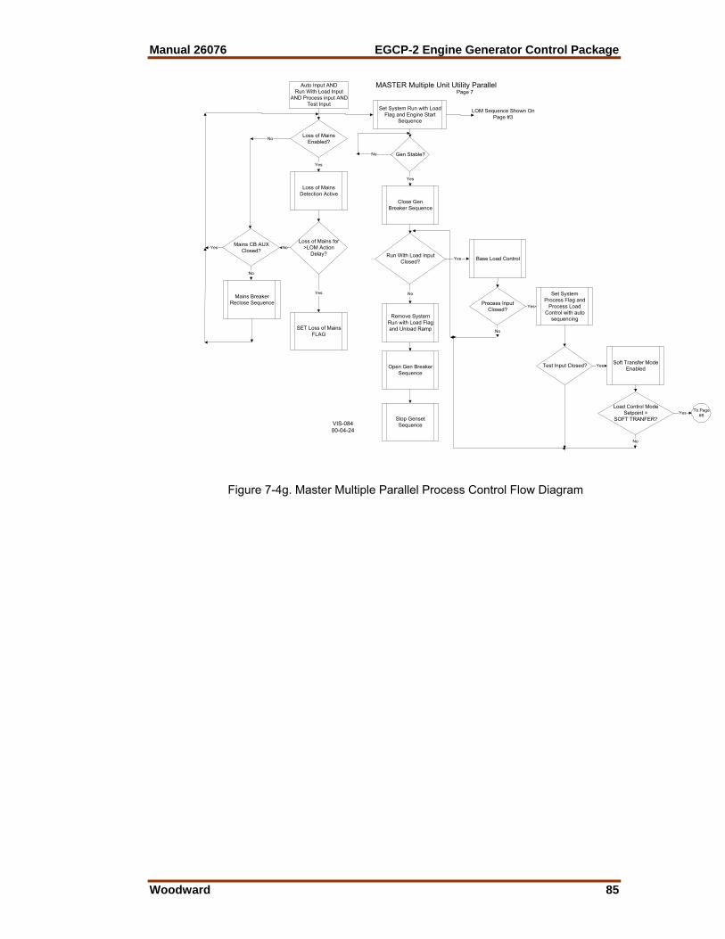
Manual 26076 EGCP-2 Engine Generator Control Package
Woodward 85
Auto Input AND
Run With Load InputAND Process input AND
Test Input
Loss of MainsEnabled?
Loss of MainsDetection Active
Loss of Mains for>LOM Action
Delay?
Yes
Mains CB AUXClosed?
Mains BreakerReclose Sequence
No
No
No
Yes
Set System Run with LoadFlag and Engine Start
Sequence
Gen Stable?
Close GenBreaker Sequence
Run With Load InputClosed?
Yes
No
Open Gen BreakerSequence
Stop GensetSequence
Remove SystemRun with Load Flagand Unload Ramp
Base Load Control
Yes
No
Yes
SET Loss of MainsFLAG
LOM Sequence Shown OnPage #3
Process InputClosed?
No
Yes Soft Transfer ModeEnabled
Load Control ModeSetpoint =
SOFT TRANFER?
No
Yes To Page#8
Set SystemProcess Flag and
Process LoadControl with auto
sequencing
Yes
Test Input Closed?
MASTER Multiple Unit Utility ParallelPage 7
VIS-08400-04-24
Figure 7-4g. Master Multiple Parallel Process Control Flow Diagram

EGCP-2 Engine Generator Control Package Manual 26076
86 Woodward
Yes Process mA input =Process Reference?
Yes
No
Mains BreakerOpen Sequence
Isoch Load Controlwith auto
sequencing
Run with Load andProcess and Test Switch
Closed?No
Yes
Test Switch Opened? No
Yes
Mains BreakerClose Sequence
Set SystemProcess Flag and
Process LoadControl with auto
sequencing
Run with Load SwitchOpened? No
Process LoadControl
Yes
Remove SystemRun with Load Flagand Unload Ramp
Open Gen BreakerSequence
Stop GensetSequence
FromPage #7
Process Switch Opened? No
Yes
Remove SystemProcess Flag andBase Load Control
MASTER Multiple Unit Utility ParallelPage 8
VIS-08500-04-24
Figure 7-4h. Master Multiple Parallel Process Control Flow Diagram

Manual 26076 EGCP-2 Engine Generator Control Package
Woodward 87
SLAVE Multiple Unit Mains ParallelTest Input Auto InputRun With Load
Input
EngineStart
Sequence
Generatorand
EngineAlarms/
ShutdownsActive
EngineStart
Sequence
Unit will not close genbreaker (must be in AUTOmode for breaker control)
Loss of MainsEnabled?
Loss of MainsDetection Active
Loss of Mains for>LOM Action
Delay?
Open MainsBreaker Sequence
Genset StartSequence
Gen Stable?Mains Stable?
Close Gen BreakerSequence
Isoch Load Controlwith sequencing
Mains Stable?
Yes
Mains CB AUXClosed?
Mains BreakerReclose Sequence
No
No
Yes
Yes
No
Yes
No
Yes
No
Yes
Master CloseMains Breaker
Sequence
Stop GensetSequence
No
Yes
Master CloseMains Breaker
Sequence
Stop GensetSequence
Open Gen BreakerSequence
Unload Ramp
Page1
VIS-08600-04-24
Figure 7-5a. Slave Multiple Parallel Process Control Flow Diagram

EGCP-2 Engine Generator Control Package Manual 26076
88 Woodward
Auto Input ANDRun With Load
Input
Loss of MainsEnabled?
Loss of MainsDetection Active
Loss of Mains for>LOM Action
Delay?
Yes
Mains CB AUXClosed?
Close MainsBreaker Sequence
No
No
No
Yes
EngineStart
Sequence
Gen Stable? OR Loss ofMains FLAG?
Open MainsBreaker Sequence
Close Gen BreakerSequence
Run With Load InputClosed? OR Loss Of
Mains FLAG?Yes
No
Close MainsBreaker Sequence
Stop GensetSequence
Open Gen BreakerSequence
Isoch Load Control
Gen CB AuxClosed?
No
Yes
Yes
No
Yes
SET Loss of MainsFLAG
Loss of MainsFLAG?
No
Yes Gen Stable?
Yes
No
SLAVE Multiple Unit No ParallelPage 2
VIS-08700-04-24
Figure 7-5b. Slave Multiple Parallel Process Control Flow Diagram
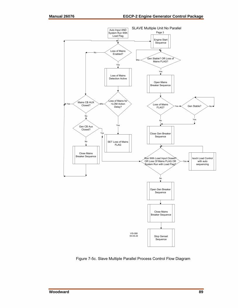
Manual 26076 EGCP-2 Engine Generator Control Package
Woodward 89
Auto Input AND
System Run WithLoad Flag
Loss of MainsEnabled?
Loss of MainsDetection Active
Loss of Mains for>LOM Action
Delay?
Yes
Mains CB AUXClosed?
Close MainsBreaker Sequence
No
No
No
Yes
Engine StartSequence
Gen Stable? OR Loss ofMains FLAG?
Open MainsBreaker Sequence
Close Gen BreakerSequence
Run With Load Input Closed?OR Loss Of Mains FLAG ORSystem Run with Load Flag?
Yes
No
Close MainsBreaker Sequence
Stop GensetSequence
Open Gen BreakerSequence
Isoch Load Controlwith auto
sequencing
Gen CB AuxClosed?
No
Yes
Yes
No
Yes
SET Loss of MainsFLAG
Loss of MainsFLAG?
No
Yes Gen Stable?
Yes
No
SLAVE Multiple Unit No ParallelPage 3
VIS-08800-04-24
Figure 7-5c. Slave Multiple Parallel Process Control Flow Diagram
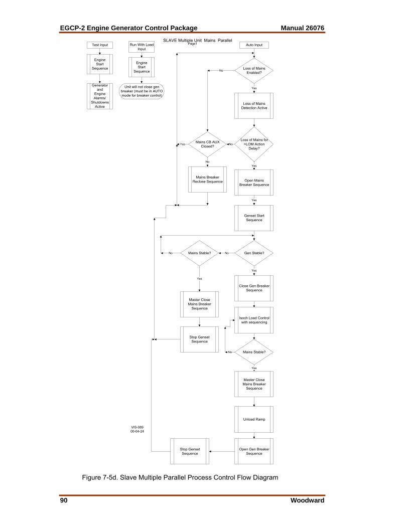
EGCP-2 Engine Generator Control Package Manual 26076
90 Woodward
SLAVE Multiple Unit Mains ParallelTest Input Auto InputRun With Load
Input
EngineStart
Sequence
Generatorand
EngineAlarms/
ShutdownsActive
EngineStart
Sequence
Unit will not close genbreaker (must be in AUTOmode for breaker control)
Loss of MainsEnabled?
Loss of MainsDetection Active
Loss of Mains for>LOM Action
Delay?
Open MainsBreaker Sequence
Genset StartSequence
Gen Stable?Mains Stable?
Close Gen BreakerSequence
Isoch Load Controlwith sequencing
Mains Stable?
Yes
Mains CB AUXClosed?
Mains BreakerReclose Sequence
No
No
Yes
Yes
No
Yes
No
Yes
No
Yes
Master CloseMains Breaker
Sequence
Stop GensetSequence
No
Yes
Master CloseMains Breaker
Sequence
Stop GensetSequence
Open Gen BreakerSequence
Unload Ramp
Page1
VIS-08900-04-24
Figure 7-5d. Slave Multiple Parallel Process Control Flow Diagram

Manual 26076 EGCP-2 Engine Generator Control Package
Woodward 91
Auto Input ANDRun With Load
Input
Loss of MainsEnabled?
Loss of MainsDetection Active
Loss of Mains for>LOM Action
Delay?
Yes
Mains CB AUXClosed?
Mains BreakerReclose Sequence
No
No
No
Yes
EngineStart
Sequence
Gen Stable?
Close GenBreaker Sequence
Run With Load InputClosed? Yes
No
Open Gen BreakerSequence
Stop GensetSequence
Unload Ramp
Base Load Control
Yes
No
Yes
SET Loss of MainsFLAG
LOM Sequence Shown OnPage #3
SLAVE Multiple Unit Mains ParallelPage 2
VIS-09000-04-24
Figure 7-5e. Slave Multiple Parallel Process Control Flow Diagram
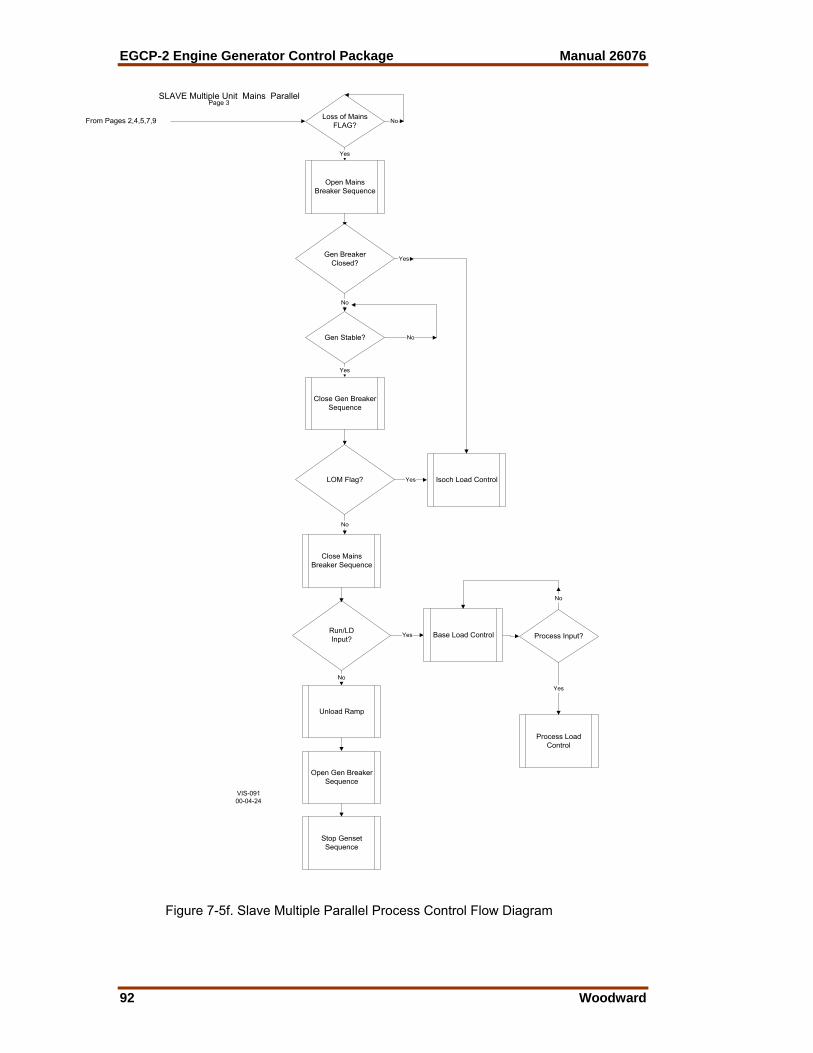
EGCP-2 Engine Generator Control Package Manual 26076
92 Woodward
Close Gen BreakerSequence
Loss of MainsFLAG? No
Yes
Gen Stable?
Open MainsBreaker Sequence
LOM Flag? Yes Isoch Load Control
Gen BreakerClosed?
No
Close MainsBreaker Sequence
Run/LDInput?
Yes Base Load Control
Unload Ramp
Open Gen BreakerSequence
Stop GensetSequence
No
Yes
No
No
Yes
Process Input?
Yes
Process LoadControl
No
From Pages 2,4,5,7,9
SLAVE Multiple Unit Mains ParallelPage 3
VIS-09100-04-24
Figure 7-5f. Slave Multiple Parallel Process Control Flow Diagram

Manual 26076 EGCP-2 Engine Generator Control Package
Woodward 93
Auto Input ANDRun With Load
Input ANDProcess
Loss of MainsEnabled?
Loss of MainsDetection Active
Loss of Mains for>LOM Action
Delay?
Yes
Mains CB AUXClosed?
Mains BreakerReclose Sequence
No
No
No
Yes
EngineStart
Sequence
Gen Stable?
Close GenBreaker Sequence
Run With Load InputClosed?
Yes
No
Open Gen BreakerSequence
Stop GensetSequence
Unload Ramp
Base Load Control
Yes
No
Yes
SET Loss of MainsFLAG
LOM Sequence Shown OnPage #3
Process InputClosed?
No
YesProcess Load
Control
SLAVE Multiple Unit Mains ParallelPage 4
VIS-09200-04-24
Figure 7-5g. Slave Multiple Parallel Process Control Flow Diagram

EGCP-2 Engine Generator Control Package Manual 26076
94 Woodward
Auto Input ANDRun With LoadInput AND Test
Loss of MainsEnabled?
Loss of MainsDetection Active
Loss of Mains for>LOM Action
Delay?
Yes
Mains CB AUXClosed?
Mains BreakerReclose Sequence
No
No
No
Yes
EngineStart
Sequence
Gen Stable?
Close GenBreaker Sequence
Run With Load InputClosed? Yes
No
Open Gen BreakerSequence
Stop GensetSequence
Unload Ramp
Base Load Control
Yes
No
Yes
SET Loss of MainsFLAG
LOM Sequence Shown OnPage #3
Test Input Closed?
No
Yes Soft Transfer ModeEnabled
Load Control ModeSetpoint =
SOFT TRANFER?
No
Yes To Page#6
SLAVE Multiple Unit Mains ParallelPage 5
VIS-09300-04-24
Figure 7-5h. Slave Multiple Parallel Process Control Flow Diagram

Manual 26076 EGCP-2 Engine Generator Control Package
Woodward 95
YesGen KW = BaseloadRefernece Setpoint?
Yes
No
Mains BreakerOpen Sequence
Isoch Load Control
Run with Load and TestSwitch Closed? No
Yes
Test Switch Opened? No
Yes
Mains BreakerClose Sequence
Base Load Control
Run with Load SwitchOpened? No Base Load Control
Yes
Unload Ramp
Open Gen BreakerSequence
Stop GensetSequence
FromPage #5
SLAVE Multiple Unit Mains ParallelPage 6
VIS-09400-04-24
Figure 7-5j. Slave Multiple Parallel Process Control Flow Diagram

EGCP-2 Engine Generator Control Package Manual 26076
96 Woodward
Auto Input AND
Run With Load InputAND Process input AND
Test Input
Loss of MainsEnabled?
Loss of MainsDetection Active
Loss of Mains for>LOM Action
Delay?
Yes
Mains CB AUXClosed?
Mains BreakerReclose Sequence
No
No
No
Yes
EngineStart
Sequence
Gen Stable?
Close GenBreaker Sequence
Run With Load InputClosed?
Yes
No
Open Gen BreakerSequence
Stop GensetSequence
Unload Ramp
Base Load Control
Yes
No
Yes
SET Loss of MainsFLAG
LOM Sequence Shown OnPage #3
Process InputClosed?
No
Yes Soft Transfer ModeEnabled
Load Control ModeSetpoint =
SOFT TRANFER?
No
Yes To Page#8
Process LoadControlYes
Test Input Closed?
SLAVE Multiple Unit Mains ParallelPage 7
VIS-09500-04-24
Figure 7-5k. Slave Multiple Parallel Process Control Flow Diagram
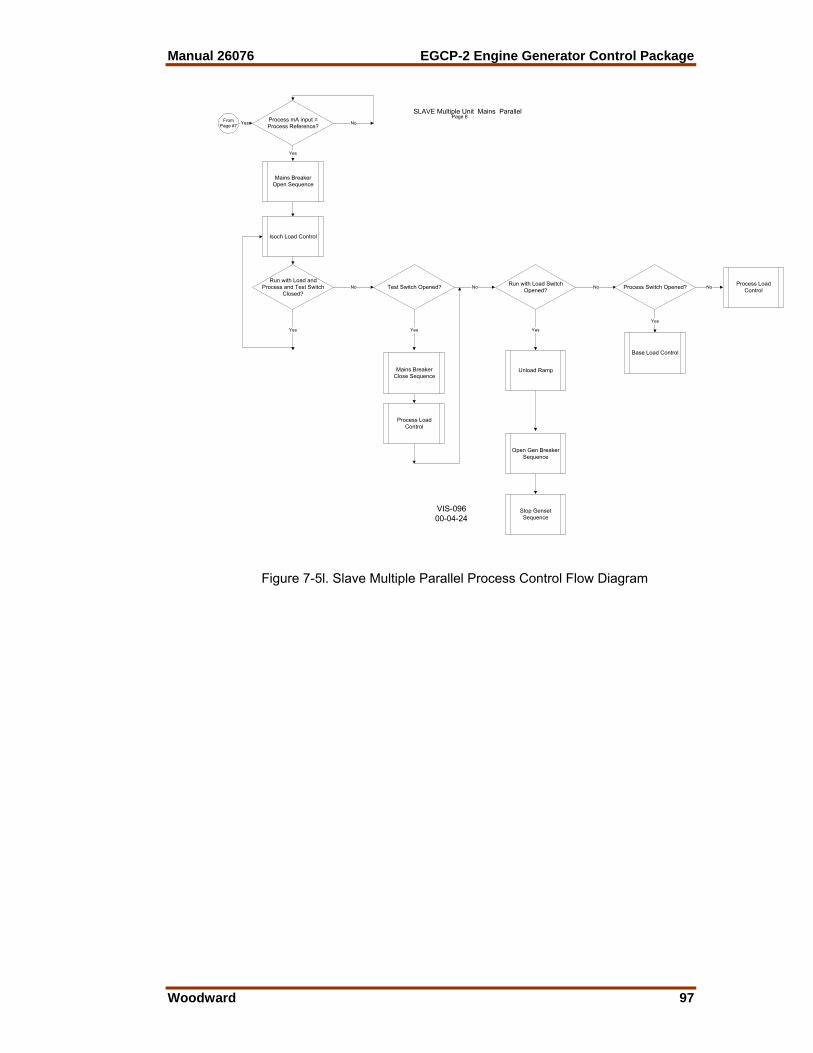
Manual 26076 EGCP-2 Engine Generator Control Package
Woodward 97
YesProcess mA input =Process Reference?
Yes
No
Mains BreakerOpen Sequence
Isoch Load Control
Run with Load andProcess and Test Switch
Closed?No
Yes
Test Switch Opened? No
Yes
Mains BreakerClose Sequence
Process LoadControl
Run with Load SwitchOpened? No
Process LoadControl
Yes
Unload Ramp
Open Gen BreakerSequence
Stop GensetSequence
FromPage #7
Process Switch Opened? No
Yes
Base Load Control
SLAVE Multiple Unit Mains ParallelPage 8
VIS-09600-04-24
Figure 7-5l. Slave Multiple Parallel Process Control Flow Diagram
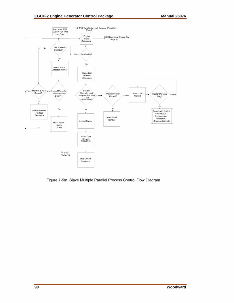
EGCP-2 Engine Generator Control Package Manual 26076
98 Woodward
Auto Input AND
System Run WithLoad Flag
Loss of MainsEnabled?
Loss of MainsDetection Active
Loss of Mains for>LOM Action
Delay?
Yes
Mains CB AUXClosed?
Mains BreakerReclose
Sequence
No
No
No
Yes
EngineStart
Sequence
Gen Stable?
Close GenBreaker
Sequence
SystemRun with Load
Flag OR Run WithLoad
Input Closed?
Yes
No
Open GenBreaker
Sequence
Stop GensetSequence
Unload Ramp
Base LoadControl
Yes
No
Yes
SET Loss ofMainsFLAG
LOM Sequence Shown OnPage #3
Mains BreakerClosed? Yes
No
Isoch LoadControl
Master ProcessFlag?
Yes
Base Load ControlWith MasterSystem LoadReference
(Process Control)
No
SLAVE Multiple Unit Mains ParallelPage 9
VIS-09700-04-24
Figure 7-5m. Slave Multiple Parallel Process Control Flow Diagram
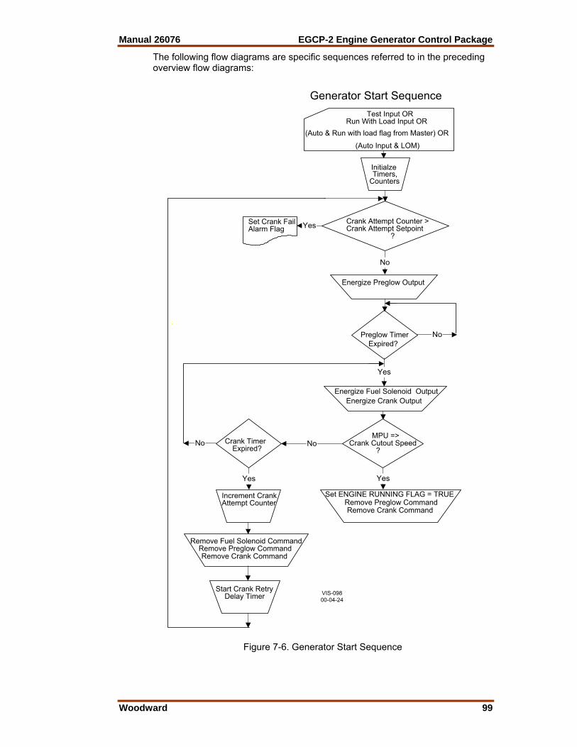
Manual 26076 EGCP-2 Engine Generator Control Package
Woodward 99
The following flow diagrams are specific sequences referred to in the preceding overview flow diagrams:
Generator Start SequenceTest Input OR
Run With Load Input OR
(Auto Input & LOM)
(Auto & Run with load flag from Master) OR
Energize Preglow Output
Preglow TimerExpired?
Energize Fuel Solenoid Output Energize Crank Output
MPU =>Crank Cutout Speed ?
Crank Timer Expired?
Increment CrankAttempt Counter
Start Crank Retry Delay Timer
Remove Fuel Solenoid Command Remove Preglow Command Remove Crank Command
InitialzeTimers,
Counters
Crank Attempt Counter >Crank Attempt Setpoint
?
Set Crank FailAlarm Flag
Set ENGINE RUNNING FLAG = TRUE Remove Preglow Command Remove Crank Command
Yes
No
No
No
Yes
Yes
No
Yes
VIS-09800-04-24
Figure 7-6. Generator Start Sequence
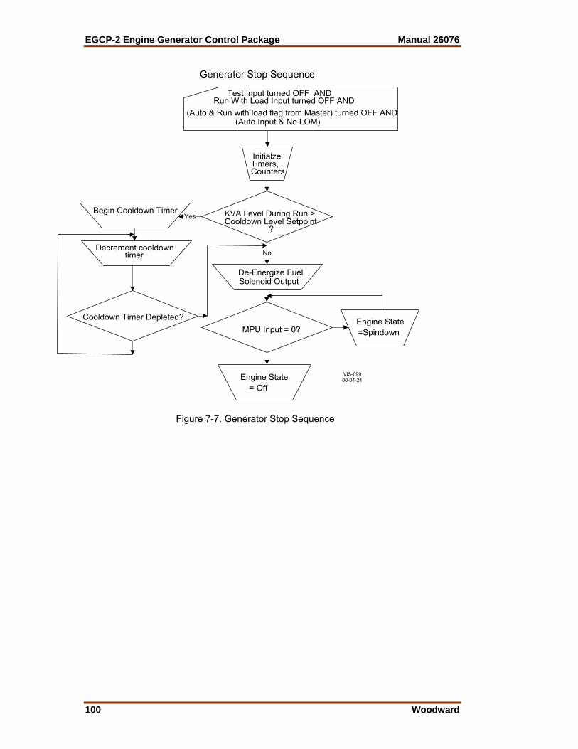
EGCP-2 Engine Generator Control Package Manual 26076
100 Woodward
Generator Stop Sequence
Test Input turned OFF ANDRun With Load Input turned OFF AND
(Auto Input & No LOM)(Auto & Run with load flag from Master) turned OFF AND
De-Energize FuelSolenoid Output
InitialzeTimers,Counters
KVA Level During Run >Cooldown Level Setpoint
?
Begin Cooldown Timer
Decrement cooldown timer
Cooldown Timer Depleted?MPU Input = 0?
Engine State =Spindown
Engine State = Off
No
Yes
VIS-09900-04-24
Figure 7-7. Generator Stop Sequence

Manual 26076 EGCP-2 Engine Generator Control Package
Woodward 101
Gen Breaker Close SequenceSingle No Mains Parallel Unit
Close Gen Breaker FLAG = TRUE
Switch PT input to Bus Sensing
Initialize Timers, Counters
Dead Bus?(Bus PT Input < 40VAC)
Dead Bus Closing ENABLED?
Breaker Logic?
Energize Breaker Open Command
Energize BreakerClose Command
Gen CB Aux Input?
Gen Breaker Hold Timer Expired?
Increment Close Attempts Reset Close Timer
De-EnergizeBreaker Open Command
De-EnergizeBreaker Close CommandGen Breaker Hold
Timer Expired?
Sync SuccessfulSet Mode Flag= IN SYNC
Close Attempts <Close Attempts Setpoint?
Energize BreakerClose Command
Breaker Logic?
Start RecloseDelay Timer
Set SyncReclose Alarm Sync Timeout
Time Expired?
Set SyncReclose Alarm
Force SyncMode = OFF
Force SyncMode = OFF
YES
YES
YES
Sync TimeoutTime Expired?
Set SyncReclose Alarm
Force SyncMode = OFF
No
Yes
No
No
No
YES
No
YES
No
YES
No
No
No
YES
YES
No
VIS-10000-04-25
Figure 7-8. Generator Breaker Close Sequence (Single No Mains Parallel)

EGCP-2 Engine Generator Control Package Manual 26076
102 Woodward
Gen Breaker Close SequenceSingle Mains Parallel Unit
Close Gen Breaker FLAG = TRUE
Switch PT input to Bus Sensing
Initialize Timers, Counters
Close Attempts <Close Attempts Setpoint?
Set SyncReclose Alarm
Sync TimeoutTime Expired?
Set SyncReclose Alarm
Force SyncMode = OFF
Force SyncMode = OFF
YES
YES
Mains CB Aux = TRUE?Sync Mode =Permissive?
Sync Mode = Run?
Dead Bus?(Bus PT Input < 40VAC)
Dead Bus Closing ENABLED?
Breaker Logic?
Energize Breaker Open Command
Energize BreakerClose Command
Gen CB Aux Input?
Gen Breaker Hold Timer Expired?
Increment Close Attempts Reset Close Timer
De-EnergizeBreaker Open Command
De-EnergizeBreaker Close CommandGen Breaker Hold
Timer Expired?
Sync SuccessfulSet Mode Flag= IN SYNC
Energize BreakerClose Command
Breaker Logic?
Start RecloseDelay Timer
YES
YES
YES
NOAdjust Speed Bias
Voltage Matching Enabled?
Adjust Volt Bias
NO
Phase <=Phase Window?
Voltage Error <= Voltage Window?
Sync Mode = Check?
No
No
No
No
No
No
YES
YES
NoNo
YES
YES
No
VIS-10100-04-25
Figure 7-9. Generator Breaker Close Sequence
(Single Mains Parallel)

Manual 26076 EGCP-2 Engine Generator Control Package
Woodward 103
Gen Breaker Close SequenceMultiple No Mains Parallel Unit
Close Gen Breaker FLAG = TRUE
Switch PT input to Bus Sensing
Initialize Timers, Counters
Close Attempts <Close Attempts Setpoint?
Set SyncReclose Alarm
Sync TimeoutTime Expired?
Set SyncReclose Alarm
Force SyncMode = OFF
Force SyncMode = OFF
NO
NO
YES
YES
Mains Breaker OPENand Live (>40VAC)
Bus?
Sync Mode =Permissive?
Sync Mode = Run?
NOAdjust Speed Bias
Voltage Matching Enabled?
Adjust Volt Bias
NO
Phase <= Phase Window?
Voltage Error <= Voltage Window?
Sync Mode = Check?
YES YES
YES
NONO
NO
NO
YES
YES
YES
NO
YES
Dead Bus?(Bus PT Input < 40VAC)
Dead Bus Closing ENABLED?
Breaker Logic?
Energize Breaker Open Command
Energize BreakerClose Command
Gen CB Aux Input?
Gen Breaker Hold Timer Expired?
Increment Close Attempts Reset Close Timer
De-EnergizeBreaker Open Command
De-EnergizeBreaker Close CommandGen Breaker Hold
Timer Expired?
Sync SuccessfulSet Mode Flag
= IN SYNC
Energize BreakerClose Command
Breaker Logic?
Start RecloseDelay Timer
NO
NO
NO
NO
NO
NO
NO
YES
YES
YES
YESYES
YES
YES
Dead Bus Token Granted?
YES
NO
Check Mode? YES
NO
VIS-10200-04-26
Figure 7-10. Generator Breaker Close Sequence (Multiple No Mains Parallel)
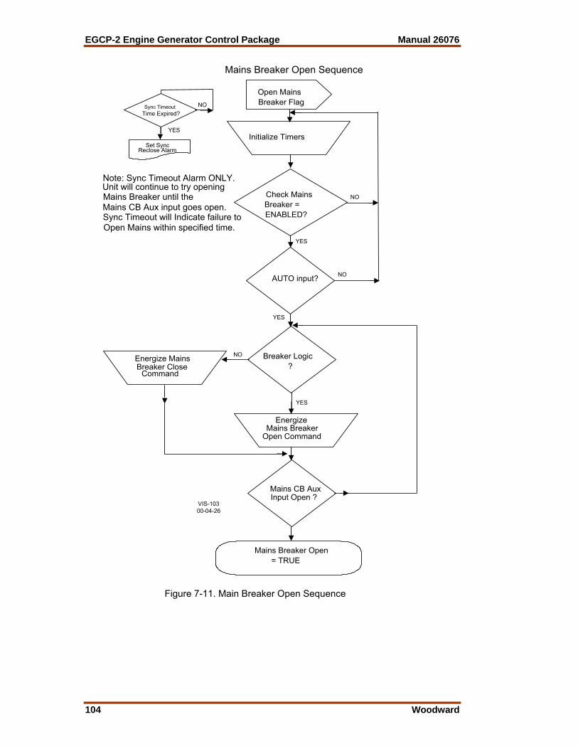
EGCP-2 Engine Generator Control Package Manual 26076
104 Woodward
Open MainsBreaker Flag
Initialize Timers
Breaker Logic ?
EnergizeMains Breaker
Open Command
Energize MainsBreaker Close
Command
Mains CB AuxInput Open ?
Check MainsBreaker =ENABLED?
AUTO input?
Sync TimeoutTime Expired?
Set SyncReclose Alarm
NO
YES
NO
NO
YES
YES
YES
NO
Note: Sync Timeout Alarm ONLY.Unit will continue to try openingMains Breaker until theMains CB Aux input goes open.Sync Timeout will Indicate failure toOpen Mains within specified time.
Mains Breaker Open = TRUE
Mains Breaker Open Sequence
VIS-10300-04-26
Figure 7-11. Main Breaker Open Sequence

Manual 26076 EGCP-2 Engine Generator Control Package
Woodward 105
Close MainsBreaker Flag
Initialize Timers, Counters
Close Attempts >Close Attempts
Setpoint?
GeneratorCB Aux?
Monitor BusPT
DeadBus?
MainsStable?
SyncCheck?
BreakerLogic
De-Energize Mains Breaker Open
Command
De-Energize Mains Breaker
Close
Energize Mains Breaker Close
Command
Mains CBAux?
Decrement HoldTimer
Hold Timer Expired?
SyncSuccessful
Start RecloseDelay
DecrementDelay
Reclose DelayTimer Expired?
Increment Close Attempts
Decrement HoldTimer Hold Timer
Expired?
MonitorMains
PT
De-Energize Mains Breaker Close
Energize MainsBreaker Close Command
BreakerLogic?
Synchro OFF,Reclose Alarm
Parallel Mains Breaker Close Diagram
NO
NO
NO
NO
NO
NO
NO
NO
NO
NO
YES
YES
YES
YESYES
YES
YES
YES
YES
YES
Unit in Auto?
YES
YES
NO
NO
YES
Note: To Clear Mains Reclose Failure,Cycle Run W/ Load Inputfrom OFF to ON to OFF.
Phase <=Phase Window?
AdjustSpeed
Bias
Voltage <=Voltage Window?
Adjust Volt
Bias
Voltage Matching= ENABLED?
In Phase
=> Dwell Time?
Sync Mode = CHECK?
Sync Mode =PERMISSIVE?
Sync Mode =PERMISSIVE?
NO
NO
NO
NO
NO
NO
NO
YES YES
YES YES
YES
YES
YES
Check MainsBreaker =Enabled?
Command
Window for
VIS-10400-04-26
Figure 7-12. Mains Breaker Close Sequence
(Mains Parallel)
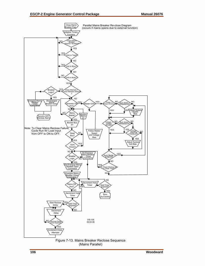
EGCP-2 Engine Generator Control Package Manual 26076
106 Woodward
Close Mains
Breaker Flag
Initialize Timers, Counters
Close Attempts >Close Attempts Setpoint
?
Generator CBAux?
Monitor BusPT
DeadBus?
MainsStable?
SyncCheck?
BreakerLogic
De-Energize Mains Breaker Open
Command
De-Energize Mains Breaker
Close
Energize Mains Breaker Close
Command
Mains CBAux?
Decrement HoldTimer
Hold Timer Expired?
SyncSuccessful
Start RecloseDelay
DecrementDelay
Reclose DelayTimer Expired?
Increment Close Attempts
Decrement HoldTimer Hold Timer
Expired?
MonitorMains
PT
De-Energize Breaker Close
Energize MainsBreaker
Command
BreakerLogic?
Synchro OFF,Reclose Alarm
Parallel Mains Breaker Re-close Diagram(occurs if mains opens due to external function)
NO
NO
NO
NO
NO
NO
NO
NO
NO
NO
YES
YES
YES
YES
YES
YES
YES
YES
YES
YES
Unit in Test?
Unit in Run?
Unit in Auto?
NO
YES
YES
YES
NO
NO
YES
Note: To Clear Mains Reclose Failure,Cycle Run W/ Load Inputfrom OFF to ON to OFF.
Check Mains
Setpoint =Enabled?
YES
NO
Phase <=Phase Window?
Adjust System
Bias
Voltage <=Voltage
Adjust System Volt Bias
Voltage
= ENABLED?
In Phase Window for=> Dwell Time?
Sync Mode = CHECK?
Sync Mode =PERMISSIVE?
Sync Mode =PERMISSIVE?
NO
NO
NO
NO
NO
NO
NO
YES YES
YES YES
YES
YES
YES
Master Unit?YES
Follow MasterSpeed
and VoltageBias
Breaker
CloseMains
Window?
Speed
Matching
Command
VIS-10500-04-26
Figure 7-13. Mains Breaker Reclose Sequence
(Mains Parallel)
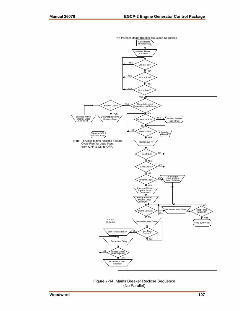
Manual 26076 EGCP-2 Engine Generator Control Package
Woodward 107
Close MainsBreaker Flag
Initialize Timers, Counters
Close Attempts >Close Attempts Setpoint ?
Generator CB Aux?
Monitor Bus PT
Dead Bus?
Mains Stable?
Sync Check?
Breaker Logic
Energize Mains Breaker Open
Command
De-Energize Mains BreakerClose Command
Set Gen Breaker Open Flag
Energize Mains Breaker Close Command
Mains CB Aux?
Decrement Hold Timer
Hold Timer Expired?
Sync Successful
Start Reclose Delay
Decrement Delay
Reclose DelayTimer Expired?
Increment Close Attempts
Decrement Hold Timer Hold Timer Expired?
MonitorMains PT
De-Energize Mains Breaker Close
Energize MainsBreaker Close Command
Breaker Logic?
Synchro OFF,Reclose Alarm
No Parallel Mains Breaker Re-Close Sequence
NO
NO
NO
NO
NO
NO
NO
NO
NO
NO
YES
YES
YES
YES
YES
YES
YES
YES
YES
YES
Unit in Test?
Unit in Run?
Unit in Auto?
NO
YES
YES
YES
NO
NO
YES
Note: To Clear Mains Reclose Failure,Cycle Run W/ Load Inputfrom OFF to ON to OFF.
VIS-10600-04-26
Figure 7-14. Mains Breaker Reclose Sequence
(No Parallel)

EGCP-2 Engine Generator Control Package Manual 26076
108 Woodward
Switch Based Logic
(Speed Raise/Lower Contact Functionality)
GE
N B
RK
R
TIE
BR
KR
P
RO
CE
SS
X X SPEED BIAS RAISE & LOWER *
1 X DISABLED 1 1 BASELOAD SETPOINT RAISE & LOWER * 1 1 1 PROCESS SETPOINT RAISE & LOWER *
1 = Breaker/Contact closed X = Breaker/Contact open or closed * = If both the Raise & Lower contacts are closed at the same time all functionality is disabled.
Figure 7-15. Speed Raise/Lower Switch Based Logic
Switch Based Logic (Voltage Raise/Lower Contact Functionality)
GE
N B
RK
R
TIE
BR
EA
KE
R
X VOLTAGE BIAS RAISE & LOWER * 1 DISABLED 1 1 UNIT VAR/PF SETPOINT RAISE & LOWER*
1 = Breaker/Contact closed X = Breaker/Contact open or closed * = If both the Raise & Lower contacts are closed at the same time all functionality is disabled.
Figure 7-16. Voltage Raise/Lower Switch Based Logic
Manual 26076 EGCP-2 Engine Generator Control Package
Woodward 109
Chapter 8. Manual Operation
Manual (Droop) operation Manual operation is obtained by selecting the Test or Run with Load discrete inputs, with the EGCP-2 in either: 1. Configured Droop a. In “Real Load Control” menu i. “Load Control Mode” is set for KW Droop b. The EGCP-2 is operated with Discrete Input # 8, Generator Breaker
Aux Contact, being closed when connected to a load or the mains (utility).
2. Manual Droop a. In “Real Load Control” menu i. “Load Control Mode” is set for Normal or Soft Transfer b. The EGCP-2 is operated with Discrete Input # 8, Generator Breaker
Aux Contact, being kept open when connected to a load or the mains (utility).
Discrete Input #1, Automatic mode, cannot be closed for Manual operation. Manual Operation – Configured Droop 1. TEST, Discrete Input #2, or RUN with LOAD, Discrete input #3, is
selected a. The EGCP-2 goes through the start sequence. b. The operator can manually raise and lower the speed and voltage. c. The generator breaker (G52) can be manually closed. i. Discrete Output #10, “Generator Breaker Trip (open)”, will stay
in the Trip position. The user must wire around the Trip command in order to manually close the breaker.
d. The EGCP-2 can be in a single or multiple unit / Mains Parallel e. Mains is Stable f. Mains Breaker is closed g. Unit operates in KW Droop i. Adjust Load with Speed Raise and Lower inputs ii. Adjust Power Factor with Voltage Raise and Lower inputs h. Unload Generator i. Open Generator Breaker Externally (Manually) j. Open Test or Run with Load input k. Engine will “cool down” and then shutdown 2. Shutdowns and Alarms a. The EGCP-2 does NOT control the Generator Breaker when in a
Manual operating mode. This means that during a Soft or Hard shutdown sequence, the EGCP-2 cannot open the Generator Breaker (G52).
b. A Soft or Hard shutdown command will react the same.

EGCP-2 Engine Generator Control Package Manual 26076
110 Woodward
3. Operating Information a. The Generator Breaker can be manually closed before the
“Generator Stable Delay” time is reached. b. If the Test or Run with Load input is opened BEFORE the generator
breaker is closed, the engine will shutdown. c. If the Test or Run with Load input is opened AFTER the generator
breaker is closed – Nothing Changes i. Engine mode stays in RUN ii. Operating State is Manual iii. Load Control State is KW Droop iv. The operator can still adjust the Load and PF using the speed
and voltage raise and lower inputs d. When the Generator Breaker is opened, the speed and voltage bias
will be reset to there “0” bias points. e. If the AUTO input is closed, with the Test input or no input the
“Operating State” changes to AUTO. The “Load Control State” remains in KW Droop
f. If the AUTO input is closed with the Run with Load input the “Operating State” changes to AUTO. The “Load Control State” remains in KW Droop
i. The “Generator Breaker Trip (open)” output will energize and be in the “close” position. If the manual override of the generator breaker trip (open) is now removed, the EGCP-2 will control the opening of the generator breaker. This allows the soft and hard shutdowns in the EGCP-2 to be fully functional.
Manual Operation – Manual Droop 1. TEST, Discrete Input #2, or RUN with LOAD, Discrete Input #3, is
selected a. The EGCP-2 goes through the start sequence b. The operator can manually raise and lower the speed and voltage c. The generator breaker (G52) can be manually closed i. Discrete Output #10, “Generator Breaker Trip (open)”, will stay
in the Trip position. The user must wire around the Trip command in order to manually close the breaker.
d. The EGCP-2 can be in a single or multiple unit / Mains Parallel e. Mains is stable f. Mains Breaker is closed g. Unit operates in KW Droop i. Adjust Load with Speed Raise and Lower inputs ii. Adjust Power Factor with Voltage Raise and Lower inputs h. Unload Generator i. Open Generator Breaker Externally (Manually) j. Open Test or Run with Load input k. Engine will “cool down” and then shutdown
Manual 26076 EGCP-2 Engine Generator Control Package
Woodward 111
2. Shutdowns and Alarms a. The EGCP-2 does NOT control the Generator Breaker when in a
Manual operating mode. This means that during a Soft or Hard shutdown sequence, the EGCP-2 cannot open the Generator Breaker (G52).
b. A Soft or Hard shutdown command will react the same. 3. Operating Information a. The Generator Breaker can be manually closed before the
“Generator Stable Delay” time is reached. b. If the Test or RUN with LOAD input is opened BEFORE the
generator breaker is closed, the engine will shutdown. c. If the TEST or RUN with LOAD input is opened AFTER the generator
breaker is closed - the EGCP2 i. Engine State changes from “Run” to “Cool Down” or “Shutdown” 1.) This resets the “Speed Bias” and ‘Voltage Bias” to there
“0” bias points. 2.) Depending on where the “0” speed bias was set, the
generator set could start to Load or Unload. 3.) When the Engine State goes to “Shutdown” i.) The Fuel Solenoid output will de-energize and the
engine will be in a Reverse Power state. At this point the EGCP2 cannot open the generator breaker.
ii. Operating State will remain in Manual iii. Load Control State is KW Droop iv. The operator should open the generator breaker if in this state. d. If the AUTO input is closed with the TEST input already closed i. The Operating State changes to AUTO ii. The Load Control State remains KW Droop iii. The operator can still adjust the Load and PF using the speed
and voltage raise and lower inputs. e. If the AUTO input is closed with the RUN with LOAD input already
closed i. The Operating State changes to AUTO ii. The Load Control State remains KW Droop iii. The EGCP-2 will Synchronize and give Breaker Close
commands until a Synch Reclose Alarm is gotten. The “Generator Breaker Trip (open)” output will be in the Trip position.

EGCP-2 Engine Generator Control Package Manual 26076
112 Woodward
Chapter 9. EGCP-2 Communications
Overview This Chapter is the MODBUS addresses for the following part numbers. EGCP-2 Software 8406-115 5418-002 NEW, A, & B 8406-116 5418-002 NEW, A, & B To view the software version in the EGCP-2: 1. Select Config key on front panel 2. The right side of the display will say Security Code 3. Select Enter key on front panel 4. The software version will be displayed on the bottom of the right side of
the display The EGCP-2 panel RS-422 port protocol may be selected for Modbus RTU or ServLink protocol, which uses an open protocol used by many third party software manufacturers, or UPLOAD SETPOINTS, which allows a setpoint transfer to and from the EGCP-2. To select which protocol will be used, enter the configuration menu of the EGCP-2 panel using the proper software password, and scroll to the menu item labeled: 422 Protocol. The selections under this menu item are: 1. Modbus 2. Upload Setpoints 3. ServLink
NOTE Whenever the 422 Protocol setpoint is changed, the EGCP-2 panel must be powered down, then powered up again, to reset to the proper protocol. If ServLink is chosen for the protocol selection, the EGCP-2 panel will communicate in the ServLink protocol. Woodward Governor Company’s ServLink communications protocol is a proprietary DDE interface to the EGCP-2 Control. This interface allows access to readout and setpoint variables in the unit. ServLink software must be purchased from Woodward, or its distributors, and resident on the host computer in order to access the EGCP-2 data over the RS-422 communication port. For more information about Woodward products, which use ServLink, contact your local Woodward Distributor. If Modbus is chosen, the EGCP-2 panel will communicate in MODBUS RTU protocol, and make its information available according to the address list as shown in Table 9-2. Also, the Modbus Address, Modbus Time-out, and Modbus Reset menu items become functional when the 422 Protocol is set to Modbus.
Manual 26076 EGCP-2 Engine Generator Control Package
Woodward 113
NOTE If Upload Setpoints is chosen, the EGCP-2 panel will switch to a communications mode where it is waiting to see characters on the 422 serial ports that set it to transfer the contents of the setpoint file to the PC. This task is run on the PC using the Download_D.exe DOS program. The Download_D.exe program is available for download on Woodward’s Internet web page. 1) Go to www.woodward.com/software. 2) In the box, select EGCP-2 Tools for all EGCP-2 related software available at present time. Modbus RTU Communications for the EGCP-2 Panel
The Modbus ID configuration menu item is adjustable from 1 to 247. This address identifies the Modbus Slave to the Modbus Master using this address. The Modbus address chosen for any particular EGCP-2 panel should be unique from any other devices on the Modbus network.
NOTE The Network Address of the EGCP-2 panel is not linked to the Modbus ID in any way. Modbus Time-out is located in the Sequencing and Comms configuration menu. This item is the time, in seconds, which the EGCP-2 panel will wait before either receiving a valid message from the Modbus master, or indicating a Modbus failure. The EGCP-2 panel indicates a Modbus failure in the bottom two lines of the Modbus Timeout and Modbus Reset Sequencing and Comms configuration menu items. This display shows Link failure (failure to receive a valid message from the master) as true/false, and an error number, which is associated with the type of failure. For example LF-XF 0 is the indication of a healthy Modbus connection with a Link failure of False and a failure number of 0. The Link failure is a latching-type indication, and requires the Modbus Reset menu item to be toggled from True to False in order to reset. See Table 9-3 for a list of common error numbers that may be seen in the Load Control Monitor Display. The Modbus Reset is located in Sequencing and Comms configuration menu. It is used to reset any failures indicated on the Modbus serial communications, and also to restart the Modbus Time-out timer from zero seconds. The Modbus Reset should be left at FALSE, and only turned to TRUE to provide a reset action on the Modbus. Once the reset is accomplished, the Modbus Reset must be taken back to False once again. The Modbus communications used by the EGCP-2 panel operate at 9600 baud, with 8 data bits, 1 stop bit, NO parity, and NO flow control. The protocol used is Modbus RTU (Master/Slave).

EGCP-2 Engine Generator Control Package Manual 26076
114 Woodward
Reply Time-out, Delay, and Number of Retries for the Modbus Master must be configured to meet the requirements of the entire Modbus network and the devices communicating on that network. See Table 9-4 for more information on typical settings. Modbus Information Addresses 00001–00016 Boolean Writes The Boolean write variables can be used for remote control of the EGCP-2 over Modbus. Fourteen variables are available to mimic the fourteen discrete input switches. The Gen CB Aux input and Mains CB Aux input are not included in the Modbus addresses. They must be hard wired to the control. If remote control is desired the control must first be placed in the “Modbus Control Mode”. The Auto, Test, and Run With Load inputs are used to determine whether the control is in the Modbus control or Hardware control mode. To activate the Modbus mode all three of the addresses 00001, 00002, and 00003 must be set. It is not required that these Modbus inputs be different than the actual hardware inputs, but all three must be set before any remote control can take place. For example, if the Auto, Test, and Run With Load inputs were all open, the user could send a False command to the addresses 00001, 00002, and 00003 and the control would switch from the Hardware control mode to Modbus control, but no action would take place. Table 9-1 shows some examples of how this switching takes place.
Table 9-1. Examples of Modbus Control Mode Switching Logic Starting Mode
Auto Input 1
Test Input 2
Run WL Input 3
Auto 00001
Test 00002
Run WL 00003
Hardware Open Open Open Set to False Set to False Set to False
Result All three Modbus commands were sent so the Control mode changes from Hardware to Modbus. No action is taken because the control remains in the OFF mode.
Hardware Open Open Open Set to False Set to True Set to False
Result
All three Modbus commands were sent so the Control mode changes from Hardware to Modbus. The Test input is set to True so the control will go into the TEST mode and the engine will start. If the Modbus commands were sent one at a time in the order of Auto, Test, Run WL, it would be after the Run WL input was sent that the engine would start, because it was the third one required, not after the Test input was set True.
Modbus Open Open Open Set to True False False
Result Modbus control has already been established. None of the discrete inputs change, so the unit is placed in the AUTO mode.
Modbus Open Open to
close Open True False False
Result Modbus control was established in the AUTO mode, and the Test hardware input was closed. This will switch the control into the Hardware control mode. The unit would go in to the TEST mode and would start.
Modbus Open to
close Open Open True False False
Result
Modbus control has already been established. The Auto hardware input was closed. Since the hardware now matches the Modbus, no action is taken. The control remains in the Modbus mode until the switch configuration is made different from the Modbus inputs.

Manual 26076 EGCP-2 Engine Generator Control Package
Woodward 115
Once Modbus control has been established, the Modbus inputs can be viewed on the I/O Status screen. There is no indication that the control has seen three successful Modbus input messages. The four momentary switch inputs to the EGCP-2 (Voltage Raise/Lower, Speed Raise/Lower) are internally (EGCP-2 software) timed to open after a one second ON time. This means that if the EGCP-2 receives an ON command via Modbus for any of these four switches, the unit will turn the switch ON for one second, and then turn the input OFF. If the Modbus update for the ON command occurs again within the one-second period, the EGCP-2 will continue holding the switch ON until one second after the last active Modbus On update is received. Addresses 10001–10071 Boolean Read The Boolean Read variables are True/False inputs that show the positions of the hardware, the alarm status, and some system status readings. Boolean Read one (10001) will be true whenever the control is switching between the Mains and Bus PT’s via the PT disconnect relays. For the engine and generator alarms, variables 34 through 62 (10034–10062), these will only go true after the delay time has been satisfied and will remain true until the alarm is cleared from the alarm log. If the corresponding alarm is set to the Disable level, it will not be seen in the Modbus variable. Boolean Read 71 (10071), PF indication will be True to indicate a leading voltage and False to indicate a lagging voltage. Addresses 30001–30073 Analog Read The Analog Read variables are numeric representations showing the measured values of the control inputs, the alarm level type, and the mode of operation for certain functions of the control. These values use a signed integer format that does not support decimal places. In order to view the decimal places on certain variables the value is multiplied by a scaling variable. For analog reads 20 through 48 (30020–30048), the engine and generator alarm types, the alarm type is defined as follows: 0 = Disabled 1 = Warning 2 = Visual Alarm 3 = Audible Alarm 4 = Soft Shutdown 5 = Hard Shutdown For analog reads 49 through 53 (30049–30053), the Loss Of Mains Alarms, the alarm type is defined as follows: 0 = Disabled 1 = Warning 2 = Loss of Mains 3 = Loss of Mains with Alarms

EGCP-2 Engine Generator Control Package Manual 26076
116 Woodward
For the analog read 67, the Load Control Mode, the mode is defined as follows: 0 = Off 1 = Droop (Generator frequency will decrease as load is increased) 2 = Isochronous (On load, not in parallel with the Mains) 3 = Baseload (In parallel with the Mains, at a fixed kW setpoint) 4 = Process (In parallel with the Mains, controlling the process input) For the analog read 68, the Synchronizer Mode, the mode is defined as follows: 0 = Off 1 = ATS (Auto Transfer State. Trying to open the Mains breaker 2 = Parallel (Trying to close Mains breaker) 3 = In Sync (Gen breaker or Mains breaker was synchronized successfully.) 4 = ATS Return (Trying to Open Gen breaker) 5 = Parallel Mains (Trying to Close Mains breaker) 6 = Gen Close Timer (Gen breaker close issued, waiting for feed back to show closed) 7 = Mains Close Timer (Mains breaker close issued, waiting for feed back to show closed) 8 = Gen Sync Timer (checking for successful synchronization of the generator) 9 = Mains Sync Timer (checking for successful synchronization of the Mains breaker) For the analog read 71 (30071), the Address of the Master Unit, is only valid on controls that are in the Auto mode. Units not in Auto are not communicating with the master and cannot be relied upon. For the analog read 72 (30072), the Engine state the state is defined as follows: 1 = Off 2 = Preglow 3 = Crank 4 = Run 5 = Cooldown (engine has ran above the Cooldown setpoint and will wait before stopping) 6 = Spindown (fuel solenoid is open but engine speed is still sensed as the engine coasts down) 7 = Restart (previous start attempt has failed, so trying again.) For the analog read 73 (30073), the Synchroscope Phase Angle, will give a value between –180 and 180 degrees. Zero degrees would be in phase, negative measurements occur when in the right half of the synchroscope, and positive measurements occur when in the left half of the synchroscope. For example, if the synchroscope were showing a rotation in the clockwise direction for a generator that was slightly faster than the bus the sequence of angles would be 0, -30, -60, -90, -120, -150, 180, 150, 120, 90, 60, 30, 0… Address 40001 Analogs Write The Analog Write variable can be used to change the priority of the EGCP-2 over Modbus. To change the priority the unit must be in the AUTO mode. When multiple units are in Auto the following rules apply to changing the priority.
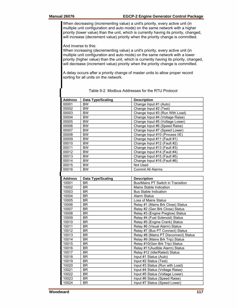
Manual 26076 EGCP-2 Engine Generator Control Package
Woodward 117
When decreasing (incrementing value) a unit's priority, every active unit (in multiple unit configuration and auto mode) on the same network with a higher priority (lower value) than the unit, which is currently having its priority, changed, will increase (decrement value) priority when the priority change is committed. And inverse to this: When increasing (decrementing value) a unit's priority, every active unit (in multiple unit configuration and auto mode) on the same network with a lower priority (higher value) than the unit, which is currently having its priority, changed, will decrease (increment value) priority when the priority change is committed. A delay occurs after a priority change of master units to allow proper record sorting for all units on the network.
Table 9-2. Modbus Addresses for the RTU Protocol Address Data Type/Scaling Description 00001 BW Change Input #1 (Auto) 00002 BW Change Input #2 (Test) 00003 BW Change Input #3 (Run With Load) 00004 BW Change Input #4 (Voltage Raise) 00005 BW Change Input #5 (Voltage Lower) 00006 BW Change Input #6 (Speed Raise) 00007 BW Change Input #7 (Speed Lower) 00008 BW Change Input #10 (Process I/E) 00009 BW Change Input #11 (Fault #1) 00010 BW Change Input #12 (Fault #2) 00011 BW Change Input #13 (Fault #3) 00012 BW Change Input #14 (Fault #4) 00013 BW Change Input #15 (Fault #5) 00014 BW Change Input #16 (Fault #6) 00015 BW Not Used 00016 BW Commit All Alarms Address Data Type/Scaling Description 10001 BR Bus/Mains PT Switch in Transition 10002 BR Mains Stable Indication 10003 BR Bus Stable Indication 10004 BR Alarm Status 10005 BR Loss of Mains Status 10006 BR Relay #1 (Mains Brk Close) Status 10007 BR Relay #2 (Gen Brk Close) Status 10008 BR Relay #3 (Engine Preglow) Status 10009 BR Relay #4 (Fuel Solenoid) Status 10010 BR Relay #5 (Engine Crank) Status 10011 BR Relay #6 (Visual Alarm) Status 10012 BR Relay #7 (Bus PT Connect) Status 10013 BR Relay #8 (Mains PT Disconnect) Status 10014 BR Relay #9 (Mains Brk Trip) Status 10015 BR Relay #10(Gen Brk Trip) Status 10016 BR Relay #11(Audible Alarm) Status 10017 BR Relay #12 (Idle/Rated) Status 10018 BR Input #1 Status (Auto) 10019 BR Input #2 Status (Test) 10020 BR Input #3 Status (Run with Load) 10021 BR Input #4 Status (Voltage Raise) 10022 BR Input #5 Status (Voltage Lower) 10023 BR Input #6 Status (Speed Raise) 10024 BR Input #7 Status (Speed Lower)

EGCP-2 Engine Generator Control Package Manual 26076
118 Woodward
Address Data Type/Scaling Description 10025 BR Input #8 Status (Gen CB Aux.) 10026 BR Input #9 Status (Mains CB Aux.) 10027 BR Input #10 Status (Process I/E) 10028 BR Input #11 Status (Fault #1) 10029 BR Input #12 Status (Fault #2) 10030 BR Input #13 Status (Fault #3) 10031 BR Input #14 Status (Fault #4) 10032 BR Input #15 Status (Fault #5) 10033 BR Input #16 Status (Fault #6) 10034 BR SYNC_TIMEOUT Status 10035 BR SYNC_RECLOSE Status 10036 BR CRANK_FAIL Status 10037 BR VOLTAGE_RANGE Status 10038 BR OVERSPEED Status 10039 BR OVERCURRENT Status 10040 BR REVERSE_POWER Status 10041 BR LOSS_OF_EXCITATION Status 10042 BR SPEED_FREQ_MISMATCH Status 10043 BR H2O_HIGH_LIMIT Status 10044 BR H2O_LOW_LIMIT Status 10045 BR OIL_PRESS_HIGH_LIMIT Status 10046 BR OIL_PRESS_LOW_LIMIT Status 10047 BR BATT_VOLT_LOW_LIMIT Status 10048 BR BATT_VOLT_HIGH_LIMIT Status 10049 BR GEN_VOLT_LOW_LIMIT Status 10050 BR GEN_VOLT_HIGH_LIMIT Status 10051 BR GEN_FREQ_HIGH_LIMIT Status 10052 BR GEN_FREQ_LOW_LIMIT Status 10053 BR LOAD_HIGH_LIMIT Status 10054 BR LOAD_LOW_LIMIT Status 10055 BR PROCESS_HIGH_LIMIT Status 10056 BR PROCESS_LOW_LIMIT Status 10057 BR REMOTE_FAULT1 Status 10058 BR REMOTE_FAULT2 Status 10059 BR REMOTE_FAULT3 Status 10060 BR REMOTE_FAULT4 Status 10061 BR REMOTE_FAULT5 Status 10062 BR REMOTE_FAULT6 Status 10063 BR Not Used 10064 BR Not Used 10065 BR Not Used 10066 BR Not Used 10067 BR Not Used 10068 BR Not Used 10069 BR Not Used 10070 BR Not Used 10071 BR PF Leading/Lagging Indicator NOTE: Analog inputs are signed integer data. Address Data Type/Scaling Description 30001 AR X10 Battery Voltage 30002 AR X10 Engine Oil Pressure 30003 AR Engine Coolant Temperature 30004 AR Engine Run Time 30005 AR Engine KW/Hours 30006 AR Engine RPM 30007 AR Phase A Volts 30008 AR Phase B Volts 30009 AR Phase C Volts
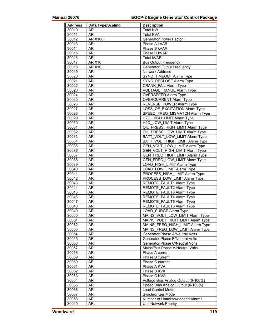
Manual 26076 EGCP-2 Engine Generator Control Package
Woodward 119
Address Data Type/Scaling Description 30010 AR Total KW 30011 AR Total KVA 30012 AR X100 Generator Power Factor 30013 AR Phase A kVAR 30014 AR Phase B kVAR 30015 AR Phase C kVAR 30016 AR Total kVAR 30017 AR X10 Bus Output Frequency 30018 AR X10 Generator Output Frequency 30019 AR Network Address 30020 AR SYNC_TIMEOUT Alarm Type 30021 AR SYNC_RECLOSE Alarm Type 30022 AR CRANK_FAIL Alarm Type 30023 AR VOLTAGE_RANGE Alarm Type 30024 AR OVERSPEED Alarm Type 30025 AR OVERCURRENT Alarm Type 30026 AR REVERSE_POWER Alarm Type 30027 AR LOSS_OF_EXCITATION Alarm Type 30028 AR SPEED_FREQ_MISMATCH Alarm Type 30029 AR H2O_HIGH_LIMIT Alarm Type 30030 AR H2O_LOW_LIMIT Alarm Type 30031 AR OIL_PRESS_HIGH_LIMIT Alarm Type 30032 AR OIL_PRESS_LOW_LIMIT Alarm Type 30033 AR BATT_VOLT_LOW_LIMIT Alarm Type 30034 AR BATT_VOLT_HIGH_LIMIT Alarm Type 30035 AR GEN_VOLT_LOW_LIMIT Alarm Type 30036 AR GEN_VOLT_HIGH_LIMIT Alarm Type 30037 AR GEN_FREQ_HIGH_LIMIT Alarm Type 30038 AR GEN_FREQ_LOW_LIMIT Alarm Type 30039 AR LOAD_HIGH_LIMIT Alarm Type 30040 AR LOAD_LOW_LIMIT Alarm Type 30041 AR PROCESS_HIGH_LIMIT Alarm Type 30042 AR PROCESS_LOW_LIMIT Alarm Type 30043 AR REMOTE_FAULT1 Alarm Type 30044 AR REMOTE_FAULT2 Alarm Type 30045 AR REMOTE_FAULT3 Alarm Type 30046 AR REMOTE_FAULT4 Alarm Type 30047 AR REMOTE_FAULT5 Alarm Type 30048 AR REMOTE_FAULT6 Alarm Type 30049 AR LOAD_SURGE Alarm Type 30050 AR MAINS_VOLT_LOW_LIMIT Alarm Type 30051 AR MAINS_VOLT_HIGH_LIMIT Alarm Type 30052 AR MAINS_FREQ_HIGH_LIMIT Alarm Type 30053 AR MAINS_FREQ_LOW_LIMIT Alarm Type 30054 AR Generator Phase A/Neutral Volts 30055 AR Generator Phase B/Neutral Volts 30056 AR Generator Phase C/Neutral Volts 30057 AR Mains/Bus Phase A/Neutral Volts 30058 AR Phase A current 30059 AR Phase B current 30060 AR Phase C current 30061 AR Phase A KVA 30062 AR Phase B KVA 30063 AR Phase C KVA 30064 AR Voltage Bias Analog Output (0-100%) 30065 AR Speed Bias Analog Output (0-100%) 30066 AR Load Control Mode 30067 AR Synchronizer Mode 30068 AR Number of Unacknowledged Alarms 30069 AR Unit Network Priority
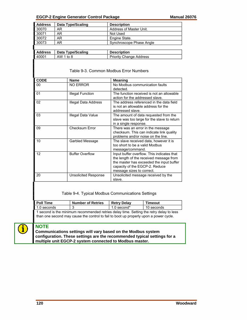
EGCP-2 Engine Generator Control Package Manual 26076
120 Woodward
Address Data Type/Scaling Description 30070 AR Address of Master Unit. 30071 AR Not Used 30072 AR Engine State. 30073 AR Synchroscope Phase Angle Address Data Type/Scaling Description 40001 AW 1 to 8 Priority Change Address
Table 9-3. Common Modbus Error Numbers CODE Name Meaning 00 NO ERROR No Modbus communication faults
detected. 01 Illegal Function The function received is not an allowable
action for the addressed slave. 02 Illegal Data Address The address referenced in the data field
is not an allowable address for the addressed slave.
03 Illegal Data Value The amount of data requested from the slave was too large for the slave to return in a single response.
09 Checksum Error There was an error in the message checksum. This can indicate link quality problems and/or noise on the line.
10 Garbled Message The slave received data, however it is too short to be a valid Modbus message/command.
12 Buffer Overflow Input buffer overflow. This indicates that the length of the received message from the master has exceeded the input buffer capacity of the EGCP-2. Reduce message sizes to correct.
20 Unsolicited Response Unsolicited message received by the slave.
Table 9-4. Typical Modbus Communications Settings Poll Time Number of Retries Retry Delay Timeout 1.0 seconds 3 1.0 second* 10 seconds 1 second is the minimum recommended retries delay time. Setting the retry delay to less than one second may cause the control to fail to boot up properly upon a power cycle.
NOTE Communications settings will vary based on the Modbus system configuration. These settings are the recommended typical settings for a multiple unit EGCP-2 system connected to Modbus master.

Manual 26076 EGCP-2 Engine Generator Control Package
Woodward 121
Chapter 10. Service Options
Product Service Options The following factory options are available for servicing Woodward equipment, based on the standard Woodward Product and Service Warranty (5-01-1205) that is in effect at the time the product is purchased from Woodward or the service is performed: • Replacement/Exchange (24-hour service) • Flat Rate Repair • Flat Rate Remanufacture If you are experiencing problems with installation or unsatisfactory performance of an installed system, the following options are available: • Consult the troubleshooting guide in the manual. • Contact Woodward technical assistance (see “How to Contact Woodward”
later in this chapter) and discuss your problem. In most cases, your problem can be resolved over the phone. If not, you can select which course of action you wish to pursue based on the available services listed in this section.
Replacement/Exchange Replacement/Exchange is a premium program designed for the user who is in need of immediate service. It allows you to request and receive a like-new replacement unit in minimum time (usually within 24 hours of the request), providing a suitable unit is available at the time of the request, thereby minimizing costly downtime. This is also a flat rate structured program and includes the full standard Woodward product warranty (Woodward Product and Service Warranty 5-01-1205). This option allows you to call in the event of an unexpected outage, or in advance of a scheduled outage, to request a replacement control unit. If the unit is available at the time of the call, it can usually be shipped out within 24 hours. You replace your field control unit with the like-new replacement and return the field unit to the Woodward facility as explained below (see “Returning Equipment for Repair” later in this chapter). Charges for the Replacement/Exchange service are based on a flat rate plus shipping expenses. You are invoiced the flat rate replacement/exchange charge plus a core charge at the time the replacement unit is shipped. If the core (field unit) is returned to Woodward within 60 days, Woodward will issue a credit for the core charge. [The core charge is the average difference between the flat rate replacement/exchange charge and the current list price of a new unit.] Return Shipment Authorization Label. To ensure prompt receipt of the core, and avoid additional charges, the package must be properly marked. A return authorization label is included with every Replacement/Exchange unit that leaves Woodward. The core should be repackaged and the return authorization label affixed to the outside of the package. Without the authorization label, receipt of the returned core could be delayed and cause additional charges to be applied.

EGCP-2 Engine Generator Control Package Manual 26076
122 Woodward
Flat Rate Repair Flat Rate Repair is available for the majority of standard products in the field. This program offers you repair service for your products with the advantage of knowing in advance what the cost will be. All repair work carries the standard Woodward service warranty (Woodward Product and Service Warranty 5-01-1205) on replaced parts and labor. Flat Rate Remanufacture Flat Rate Remanufacture is very similar to the Flat Rate Repair option with the exception that the unit will be returned to you in “like-new” condition and carry with it the full standard Woodward product warranty (Woodward Product and Service Warranty 5-01-1205). This option is applicable to mechanical products only.
Returning Equipment for Repair If a control (or any part of an electronic control) is to be returned to Woodward for repair, please contact Woodward in advance to obtain a Return Authorization Number. When shipping the item(s), attach a tag with the following information: • name and location where the control is installed; • name and phone number of contact person; • complete Woodward part number(s) and serial number(s); • description of the problem; • instructions describing the desired type of repair.
CAUTION—ELECTROSTATIC DISCHARGE To prevent damage to electronic components caused by improper handling, read and observe the precautions in Woodward manual 82715, Guide for Handling and Protection of Electronic Controls, Printed Circuit Boards, and Modules. Packing a Control Use the following materials when returning a complete control: • protective caps on any connectors; • antistatic protective bags on all electronic modules; • packing materials that will not damage the surface of the unit; • at least 100 mm (4 inches) of tightly packed, industry-approved packing
material; • a packing carton with double walls; • a strong tape around the outside of the carton for increased strength.
Manual 26076 EGCP-2 Engine Generator Control Package
Woodward 123
Return Authorization Number When returning equipment to Woodward, please telephone and ask for the Customer Service Department [1 (800) 523-2831 in North America or +1 (970) 482-5811]. They will help expedite the processing of your order through our distributors or local service facility. To expedite the repair process, contact Woodward in advance to obtain a Return Authorization Number, and arrange for issue of a purchase order for the item(s) to be repaired. No work can be started until a purchase order is received.
NOTE We highly recommend that you make arrangement in advance for return shipments. Contact a Woodward customer service representative at 1 (800) 523-2831 in North America or +1 (970) 482-5811 for instructions and for a Return Authorization Number.
Replacement Parts When ordering replacement parts for controls, include the following information: • the part number(s) (XXXX-XXXX) that is on the enclosure nameplate; • the unit serial number, which is also on the nameplate.
How to Contact Woodward In North America use the following address when shipping or corresponding: Woodward Governor Company PO Box 1519 1000 East Drake Rd Fort Collins CO 80522-1519, USA Telephone—+1 (970) 482-5811 (24 hours a day) Toll-free Phone (in North America)—1 (800) 523-2831 Fax—+1 (970) 498-3058 For assistance outside North America, call one of the following international Woodward facilities to obtain the address and phone number of the facility nearest your location where you will be able to get information and service. Facility Phone Number Brazil +55 (19) 3708 4800 India +91 (129) 230 7111 Japan +81 (476) 93-4661 The Netherlands +31 (23) 5661111 You can also contact the Woodward Customer Service Department or consult our worldwide directory on Woodward’s website (www.woodward.com) for the name of your nearest Woodward distributor or service facility.

EGCP-2 Engine Generator Control Package Manual 26076
124 Woodward
Engineering Services Woodward Industrial Controls Engineering Services offers the following after-sales support for Woodward products. For these services, you can contact us by telephone, by email, or through the Woodward website. • Technical Support • Product Training • Field Service Contact information: Telephone—+1 (970) 482-5811 Toll-free Phone (in North America)—1 (800) 523-2831 Email—[email protected] Website—www.woodward.com Technical Support is available through our many worldwide locations or our authorized distributors, depending upon the product. This service can assist you with technical questions or problem solving during normal business hours. Emergency assistance is also available during non-business hours by phoning our toll-free number and stating the urgency of your problem. For technical support, please contact us via telephone, email us, or use our website and reference Customer Services and then Technical Support. Product Training is available at many of our worldwide locations (standard classes). We also offer customized classes, which can be tailored to your needs and can be held at one of our locations or at your site. This training, conducted by experienced personnel, will assure that you will be able to maintain system reliability and availability. For information concerning training, please contact us via telephone, email us, or use our website and reference Customer Services and then Product Training. Field Service engineering on-site support is available, depending on the product and location, from one of our many worldwide locations or from one of our authorized distributors. The field engineers are experienced both on Woodward products as well as on much of the non-Woodward equipment with which our products interface. For field service engineering assistance, please contact us via telephone, email us, or use our website and reference Customer Services and then Technical Support.

Manual 26076 EGCP-2 Engine Generator Control Package
Woodward 125
Technical Assistance If you need to telephone for technical assistance, you will need to provide the following information. Please write it down here before phoning: General Your Name Site Location Phone Number Fax Number Prime Mover Information Engine/Turbine Model Number Manufacturer Number of Cylinders (if applicable) Type of Fuel (gas, gaseous, steam, etc) Rating Application Control/Governor Information Please list all Woodward governors, actuators, and electronic controls in your system: Woodward Part Number and Revision Letter Control Description or Governor Type Serial Number Woodward Part Number and Revision Letter Control Description or Governor Type Serial Number Woodward Part Number and Revision Letter Control Description or Governor Type Serial Number If you have an electronic or programmable control, please have the adjustment setting positions or the menu settings written down and with you at the time of the call.
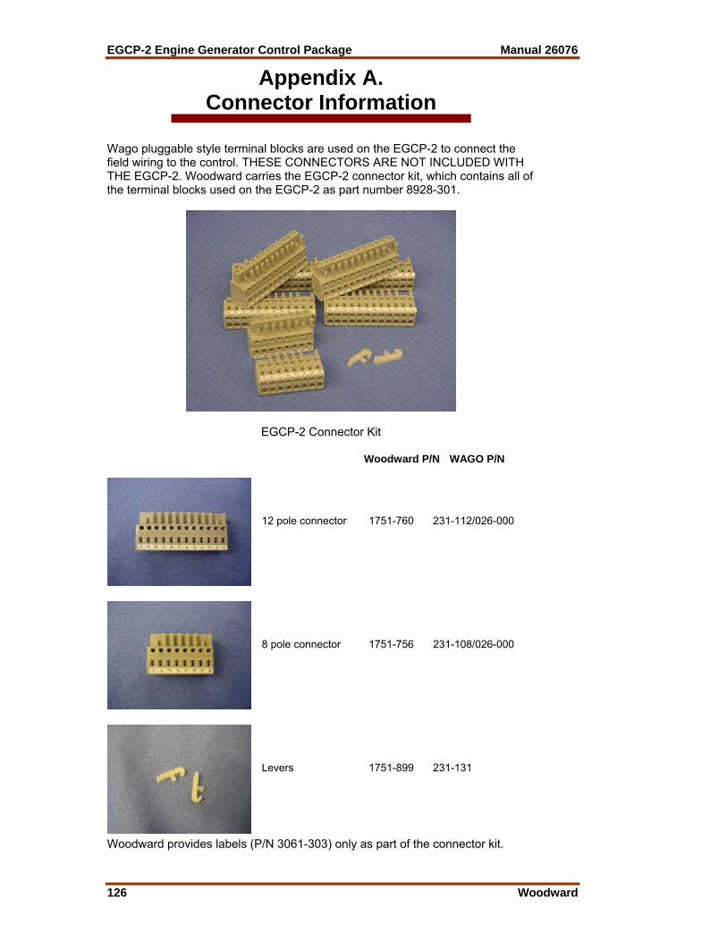
EGCP-2 Engine Generator Control Package Manual 26076
126 Woodward
Appendix A. Connector Information
Wago pluggable style terminal blocks are used on the EGCP-2 to connect the field wiring to the control. THESE CONNECTORS ARE NOT INCLUDED WITH THE EGCP-2. Woodward carries the EGCP-2 connector kit, which contains all of the terminal blocks used on the EGCP-2 as part number 8928-301.
EGCP-2 Connector Kit Woodward P/N WAGO P/N
12 pole connector 1751-760 231-112/026-000
8 pole connector 1751-756 231-108/026-000
Levers 1751-899 231-131
Woodward provides labels (P/N 3061-303) only as part of the connector kit.
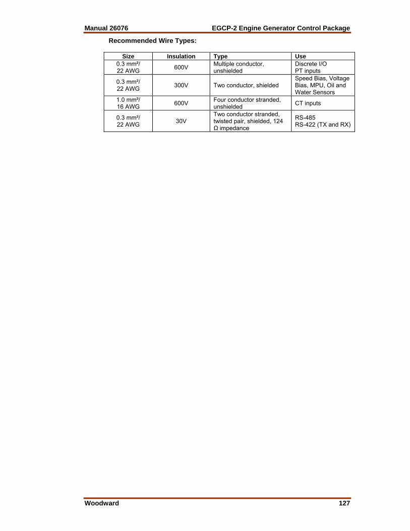
Manual 26076 EGCP-2 Engine Generator Control Package
Woodward 127
Recommended Wire Types:
Size Insulation Type Use 0.3 mm²/ 22 AWG 600V Multiple conductor,
unshielded Discrete I/O PT inputs
0.3 mm²/ 22 AWG 300V Two conductor, shielded
Speed Bias, Voltage Bias, MPU, Oil and Water Sensors
1.0 mm²/ 16 AWG 600V Four conductor stranded,
unshielded CT inputs
0.3 mm²/ 22 AWG 30V
Two conductor stranded, twisted pair, shielded, 124 Ω impedance
RS-485 RS-422 (TX and RX)

EGCP-2 Engine Generator Control Package Manual 26076
128 Woodward
Appendix B. Speed Bias Connections
VIS-125a00-06-20
EGCP-2
73
74
Speed Bias Output Type = +/- 3VDC
EGCP-2 To EPG Speed Control Wiring andConfiguration Settings
Speed Bias Output
+
-
EPGSPEED
CONTROL
VIS-126a00-06-20
EGCP-2
73
74
Speed Bias Output Type = +/- 3VDC0% Speed Bias Output = 0 VDC
Common 2301A Speed Control Part Numbers:9905-131, 9905-376, 9907-014
EGCP-2 To 2301A Speed Control Wiring andConfiguration Settings
Speed Bias Output
+
-
2301ASpeed Control
15
17
+
-

Manual 26076 EGCP-2 Engine Generator Control Package
Woodward 129
VIS-127a00-06-20
EGCP-2
73
74
Speed Bias Output Type = +/- 3VDC0% Speed Bias Output = 0 VDC
Common FLO-TECH Speed Control Part Numbers:8290-195, 8290-196
EGCP-2 To FLO-TECH Speed Control Wiring andConfiguration Settings
Speed Bias Output
+
-
FLO-TECHSpeed Control
11
12
+
-
VIS-128a00-06-20
EGCP-2
73
74
Speed Bias Output Type = +/- 3VDC0% Speed Bias Output = 0 VDC
Common Pro-ACT Speed Control Part Numbers:9905-462, 9905-463
EGCP-2 To Pro-ACT Speed Control Wiring andConfiguration Settings
Speed Bias Output
+
-
Pro-ACT I & IISpeed Control
12
13
+
-

EGCP-2 Engine Generator Control Package Manual 26076
130 Woodward
VIS-129a00-06-20
EGCP-2
73
74
Speed Bias Output Type = +/- 3VDC0% Speed Bias Output = 0 VDC
EGCP-2 To CSC Speed Control Wiring andConfiguration Settings
Speed Bias Output
+
-
CSC Speed Control
11
12
+
-
VIS-130a00-06-20
EGCP-2
73
74
Speed Bias Output Type = +/- 3VDC0% Speed Bias Output = 0 VDC
EGCP-2 To 2301A LSSC Wiring and ConfigurationSettings
Speed Bias Output
+
-
2301A LSSC Control
10
11
+
-
NOTE: 2301A LSSC must have terminal 14 powered forthe load sharing line inputs (10 and 11) to be active.

Manual 26076 EGCP-2 Engine Generator Control Package
Woodward 131
VIS-131a00-06-20
EGCP-2
73
74
Speed Bias Output Type = +/- 3VDC0% Speed Bias Output = 0 VDC
EGCP-2 To 701 and 701A Wiring and ConfigurationSettings
Speed Bias Output
+
-
701 or 701ASpeed
Control
21
22
+
-
Common 701 and 701A Speed Control Part Numbers:8280-102, 8280-193, 9905-211
Common 721 Speed Control Part Numbers:9905-291, 9907-206, 9907-207
VIS-132a00-06-20
EGCP-2
73
74
Speed Bias Output Type = +/- 3VDC0% Speed Bias Output = 0 VDC
EGCP-2 To 701 and 701A Wiring and ConfigurationSettings
Speed Bias Output
+
-
721Speed
Control
21
22
+
-
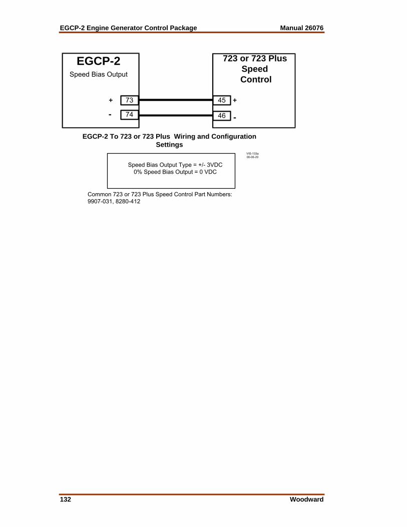
EGCP-2 Engine Generator Control Package Manual 26076
132 Woodward
VIS-133a00-06-20
EGCP-2
73
74
Speed Bias Output Type = +/- 3VDC0% Speed Bias Output = 0 VDC
EGCP-2 To 723 or 723 Plus Wiring and ConfigurationSettings
Speed Bias Output
+
-
723 or 723 PlusSpeed
Control
45
46
+
-
Common 723 or 723 Plus Speed Control Part Numbers:9907-031, 8280-412

Manual 26076 EGCP-2 Engine Generator Control Package
Woodward 133
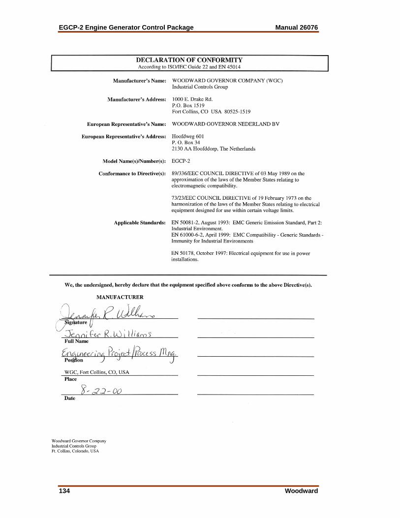
EGCP-2 Engine Generator Control Package Manual 26076
134 Woodward
Declarations

EGCP-2 Control Specifications Woodward Part Numbers: 8406-115 EGCP-2 Engine Generator Control, 150–300 Vac PT
input 8406-116 EGCP-2 Engine Generator Control, 50–150 Vac PT input Power Supply Rating 9–32 Vdc (SELV) Maximum input voltage range Power Consumption Less than or equal 13 W nominal, 20 W maximum Input Supply Voltage Input Supply Current 12 V (nominal) 1.08 A 24 V (nominal) 542 mA 32 V 406 mA PT input 50–150 Vac, 8406-116 150–300 Vac, 8406-115 CT input 0–5 A rms Generator Frequency Range 40–70 Hz Magnetic Pickup 100–15 000 Hz Discrete Inputs (8) 5 mA source current when CLOSED to Switch Common
(65) Process input 4–20 mA, 1–5 Vdc Temperature and pressure inputs 0–200 Ω sensors, 4–20 mA transducer, or 0–5V
transducer Speed Bias ±3 Vdc, 0.5–4.5 Vdc, 5 V peak 500 Hz PWM Voltage Bias ±1 Vdc, ±3 Vdc, ±9 Vdc Discrete Outputs (Relay Outputs) 10 A, 250 Vac Resistive 249 W (1/3 hp), 125 Vac (7.2 A, 0.4–0.5 PF) 10 A, 30 Vdc Resistive Communication Ports RS-485, RS-422 Ambient Operating Temperature –20 to +70 °C (–4 to +158 °F)(around outside of EGCP-2
chassis) Storage Temperature –40 to +105 °C (–40 to +221 °F) Humidity 95% at 20 to 55 °C (68 to 131 °F) Mechanical Vibration SV2 5–2000 Hz @ 4 G and RV1 10–2000 Hz @ .04
G²/Hz Mechanical Shock US MIL-STD 810C, Method 516.2, Procedure I (basic
design test), Procedure II (transit drop test, packaged), Procedure V (bench handling)
Equipment Classification Class 1 (grounded equipment) Air Quality Pollution Degree II Installation Overvoltage Category III Ingress Protection Will meet the requirements of IP56 as defined in IEC529
when installed in a suitable atmospherically vented enclosure. Also meets Type 4 requirements.

We appreciate your comments about the content of our publications.
Send comments to: [email protected]
Please include the manual number from the front cover of this publication.
PO Box 1519, Fort Collins CO 80522-1519, USA 1000 East Drake Road, Fort Collins CO 80525, USA Phone +1 (970) 482-5811 • Fax +1 (970) 498-3058
Email and Website—www.woodward.com
Woodward has company-owned plants, subsidiaries, and branches, as well as authorized distributors and other authorized service and sales facilities throughout the world.
Complete address / phone / fax / email information for all locations is available on our website.
06/5/F


