734 IEEE TRANSACTIONS ON COMPUTER-AIDED DESIGN OF INTEGRATED

260 IEEE TRANSACTIONS ON COMPUTER-AIDED DESIGN OF INTEGRATED CIRCUITS AND SYSTEMS, VOL. 35, NO. 2, FEBRUARY 2016
Fault-Tolerant Networks-on-Chip Routing WithCoarse and Fine-Grained Look-Ahead
Junxiu Liu, Student Member, IEEE, Jim Harkin, Yuhua Li, Senior Member, IEEE, and Liam P. Maguire
Abstract—Fault tolerance and adaptive capabilities are chal-lenges for modern networks-on-chip (NoC) due to the increase inphysical defects in advanced manufacturing processes. Two noveladaptive routing algorithms, namely coarse and fine-grained (FG)look-ahead algorithms, are proposed in this paper to enhance 2-Dmesh/torus NoC system fault-tolerant capabilities. These strate-gies use fault flag codes from neighboring nodes to obtain thestatus or conditions of real-time traffic in an NoC region, then cal-culate the path weights and choose the route to forward packets.This approach enables the router to minimize congestion for theadjacent connected channels and also to bypass a path with faultychannels by looking ahead at distant neighboring router paths.The novelty of the proposed routing algorithms is the weightedpath selection strategies, which make near-optimal routing deci-sions to maintain the NoC system performance under high faultrates. Results show that the proposed routing algorithms canachieve performance improvement compared to other state ofthe art works under various traffic loads and high fault rates.The routing algorithm with FG look-ahead capability achievesa higher throughput compared with the coarse-grained approachunder complex fault patterns. The hardware area/power over-heads of both routing approaches are relatively low which doesnot prohibit scalability for large-scale NoC implementations.
Index Terms—Adaptive routing, fault tolerance, hardwarereliability, look-ahead, networks-on-chip (NoC).
I. INTRODUCTION
THE COMPLEXITY of modern systems-on-chip has seenthe introduction of new interconnection strategies such
as networks-on-chip (NoC) which allow scalable on-chipcommunication between large numbers of processing compo-nents. Testing results demonstrate that even small numbersof faults in the NoC, e.g., ∼30 logic gate faults, can causebetween 5 and 50 faulty channels, which highly impair theNoC network [1]. Therefore, the provision of fault toler-ance is one challenge for modern NoCs due to the complexand large-scale application mapping structures for on-chipmultiprocessors [2]. Adaptive routing is a fault tolerance strat-egy to maintain the system functionality under the presenceof faults. Besides the basic routing functions, the fault-tolerant
Manuscript received November 3, 2014; revised February 23, 2015 andMay 27, 2015; accepted July 10, 2015. Date of publication July 22, 2015;date of current version January 19, 2016. This paper was recommended byAssociate Editor S. Kim.
J. Liu, J. Harkin, and L. P. Maguire are with the School of Computingand Intelligent Systems, University of Ulster, Derry BT48 7JL, U.K. (e-mail:[email protected]; [email protected]; [email protected]).
Y. Li is with the School of Computing, Science and Engineering, Universityof Salford, Manchester M5 4WT, U.K. (e-mail: [email protected]).
Color versions of one or more of the figures in this paper are availableonline at http://ieeexplore.ieee.org.
Digital Object Identifier 10.1109/TCAD.2015.2459050
adaptive routing algorithm should also have the capabilityto deal with: 1) complex traffic patterns and 2) interconnectconditions.
1) Complex Traffic Patterns: For most NoC applications,there are always some nodes that receive/send morepackets than other nodes (such as computing units andmemory storage nodes) and these are termed “hotspots.”This causes some channels to become busy or congestedand continuously blocked which prevent the packets tobe transmitted. The adaptive routing should choose theoptimal path to bypass the congested channel and getthe traffic balanced for the system.
2) Interconnection Conditions: Incorrect manufacturingprocedures for NoC system cause permanent faultswhich exist for the life-time of the system and cannotbe recovered; and the external perturbation from powersupply fluctuations and radiation cause transient faultswhile unstable hardware cause intermittent faults. If theNoC interconnect is faulty, the adaptive routing shouldchoose a fault-free path to forward the packets and avoidthe packets being damaged. The interconnect fault dis-tribution problem was summarized in [3]. In most ofthese fault distribution patterns, the faulty interconnectsare clustered which requires the routing algorithm tohave the capability to gauge the interconnect conditionin advance by looking ahead in each channel path andmake routing decisions in advance to avoid entering afaulty region.
In this paper, two-novel fault-tolerant adaptive routing algo-rithms with different levels of look-ahead capability are pro-posed for 2-D mesh/torus NoC embedded systems. A fault flagencoding/decoding mechanism is developed to provide infor-mation to local NoC routers on the interconnect conditionsin far distant routers. Based on this condition information,the coarse-grained (CG) and fine-grained (FG) routing algo-rithms calculate the weight for each direction or path and selectthe optimal direction to forward the packets. The fault flagencoding/decoding mechanism provides a local router withthe global traffic knowledge of a region, which aids the localrouter in making efficient routing decisions. The weight calcu-lating scheme generates the weights for the directions withina region and permits the choosing of the optimal path selectionunder complex traffic conditions. The CG and FG are dis-tributed routing algorithms. The region containing the knowntraffic conditions is a sliding window which follows the cur-rent node and is independent of the system size. The windowsize remains fixed (as defined by the degree of look-ahead)
0278-0070 c© 2015 IEEE. Personal use is permitted, but republication/redistribution requires IEEE permission.See http://www.ieee.org/publications_standards/publications/rights/index.html for more information.
brought to you by COREView metadata, citation and similar papers at core.ac.uk
provided by Online Research @ Cardiff

LIU et al.: FAULT-TOLERANT NoC ROUTING WITH COARSE AND FG LOOK-AHEAD 261
independent of the NoC size. The mechanism for routing usesthe local bounds of the window to make routing decisions asa packet propagates across the NoC. The advantage of thismechanism is that it scales with increased NoC sizes. Themain contributions of this paper include the following.
1) Novel fault-tolerant adaptive routing algorithms(CG and FG) with look-ahead functions of variousgranularities.
2) Results and detailed performance analysis of through-put and latency under varied traffic workloads and faultpatterns.
3) Validation of results against benchmarks to showimproved fault-tolerant capability.
The remainder of this paper is organized as follows.Section II provides a summary of previous work with a focuson fault-tolerant adaptive routing algorithms. Section III dis-cusses the proposed CG and FG routing algorithms andpresents the weight calculation and routing decision-makingprocess in detail. Section IV presents results and a per-formance analysis on different traffic workloads and faultpatterns for a range of experiments. Section V discusses thehardware implementation for CG and FG using application-specified integrated circuit (ASIC)/field-programmable gatearray (FPGA) technology, and presents an area/power con-sumption comparison with previous work. Section VI providesthe conclusion.
II. BACKGROUND AND PREVIOUS WORK
In the following section, a review of the current approachesfor routing algorithms is presented.
A. Traffic-Aware Adaptive Routing Algorithms
Traffic-aware adaptive NoC routers were proposedin [4] and [5], which made routing decisions based on thetraffic signals and avoided dropped packets by adapting totraffic status. Similar to [4], a path-aware routing scheme wasproposed in [6]. It used a specific subnetwork to propagatethe congestion information to aid making routing decisions;a neighbor-on-path routing algorithm [7] aimed to route pack-ets along a minimal congested path based on the traffic statusof neighboring nodes; and another path selection strategy [8]selected the output port leading to a less congested path.A hybrid path-diversity-aware adaptive routing was proposedin [9], which used both global path diversity informationand local buffer occupancy information to make routingdecisions. These adaptive routing algorithms can balancethe system load however, they are not fault-tolerant. Thefault-tolerant ability is crucial due to manufacturing and theexternal environmental interferences, especially for criticalmission electronic systems.
B. Fault-Tolerant Routing Algorithm Based on ImmediateConnected Channel Conditions
A fault-tolerant routing algorithm was proposed in [10],which could select fault-free paths after detecting faults ina node. It is only tolerant of node faults and does not sup-port link faults. Another small-granularity routing algorithmwas proposed in [11]. It supported both node and link faults,
but the maximum number of faulty links of each node waslimited to one. The routing algorithm in [12] used a rout-ing table to make routing decisions where the table wasupdated when the node or link in the system was faulty.The Gradient routing algorithm [13] chooses the alternativepath if the original path is congested or faulty. The enhanceddynamic XY routing in [14] added two signals per chan-nel to the router which indicated the traffic status in therow or column. But it can only tolerate a single link fault.A localized rerouting mechanism was employed in [15] tobypass the faulty links and regions. Redundant channels wereadded to the Y-dimension of a 2-D mesh NoC to be toler-ant of the faults in [16]. A fault-tolerant routing algorithmwas proposed in [17] based on a special NoC router whichincludes two subrouters and divides the system into twosubnetworks—an eastbound and westbound system. Based onthis router structure and a modified XY routing scheme, it cantolerate multiple faults while maintaining system performance.A fault-tolerant routing algorithm, namely FADyAD, wasproposed in [18]. It was also a congestion-aware routing algo-rithm which combined the advantages of both deterministicand adaptive routing schemes (ARSs). Most of the aforemen-tioned routing algorithms make routing decisions based solelyon the immediate channel traffic conditions, i.e., the routingalgorithms only have a local-awareness. However, if the rout-ing decision is based on traffic information comprised of notonly immediate links but also the links beyond nearest neigh-bor, then the system’s traffic can be balanced more efficientlyand the throughput of the system can be better maintained.
C. Fault-Tolerant Routing Algorithm Based on RegionalChannel Conditions
A congested aware fault-tolerant routing algorithm waspresented in [19]. It made routing decisions based on the neigh-boring link conditions (faulty or fault-free) and traffic status(i.e., idle or busy). But the faults are assumed to occur in bothdirections for the link and it only looks at the fault status onehop or link ahead. A fault-on-neighbor aware deflection routingalgorithm was proposed in [3]. It makes routing decisions basedon the link conditions within a two-hop range to avoid faultylinks and routers. A fault-tolerant deflection routing (FTDR)was proposed in [20]. It used a routing table to store the dis-tance for every direction between the current and destinationnodes. The routing table is updated if the link status changes(such as from fault-free to faulty). Based on the routing table,the current node can choose a fault-free path to forward thepackets. The main limitation of [3] and [20] is that a faulty linkhas to be shut down in both directions; e.g., the scenario whereone direction of the link is faulty and the other is fault-free,is very common and therefore makes [3] and [20] inefficient.The universal logic-based distributed routing (uLBDR) [21] wasproposed to enhance the NoC fault-tolerant capability with anefficient cost and high coverage [22]. In [23], a fault-tolerantrouting algorithm for a 2-D mesh NoC system was proposed. Fora fault-free network, it uses a hierarchical model (i.e., a generalrouting scheme similar to XY) to route the packets. If the linksor nodes are faulty, an echo model is activated which can choose

262 IEEE TRANSACTIONS ON COMPUTER-AIDED DESIGN OF INTEGRATED CIRCUITS AND SYSTEMS, VOL. 35, NO. 2, FEBRUARY 2016
a valid path for routing. The main drawback is that it increasesthe packet size linearly with the hop count in the communicationpath and can cause NoC traffic overload, especially for longdistance communication
In summary, current approaches have the aforementionedweaknesses of: 1) unable to make routing decisions undercomplex traffic status, especially for the combination of con-gested and faulty links and 2) cause system performancedegradation under high fault rates; therefore they do notmeet the required characteristics to provide an efficient rout-ing strategy for modern NoCs. For an NoC to be robust(tolerate faults) and achieve better performance, several keyfunctions need to be investigated and they include: 1) theability to obtain sufficient knowledge of the traffic infor-mation in the neighboring regions and 2) the capabilityto make the optimal routing decisions for different faultpatterns, avoid traffic starvation/overhead and balance traf-fic loads across the NoC. The mesh and torus topologiesare used in this paper which have already been used inmany applications [3], [8], [10], [13], [14], [20], and indus-trial products, e.g., Tilera processor and Nvidia graphicsprocessing unit. A novel approach is proposed which investi-gates the routing strategies that can select the fault-free andminimal congested path to route packets and reduce the over-all latency of messages and therefore, maintain the throughputperformance for the faulty NoC of mesh/torus topologies.
III. COARSE AND FINE-GRAINED ROUTING ALGORITHMS
In this section, the principles of the novel approach ofCG and FG adaptive routing are presented. The preferreddirection (PD) definition and the fault flag coding/decodingmechanism are also outlined.
A. Preferred Direction Definition
In this section, a 2-D-mesh topology is used to present theprinciple of the CG and FG algorithms. Fig. 1 presents a typ-ical 2-D-mesh NoC system, where each node is connectedto other nodes through four directions (N/E/S/W) and pro-cessing elements are connected to the router via a local port.Every node is positioned using a pair of coordinates. The nota-tion (xs, ys) is used to denote the coordinates of the sourcenode which issues packets; (xc, yc) denotes the coordinates ofthe current router where the packet is currently located as ittransverses its source to destination path; (xd, yd) denotes thecoordinates of the destination node, the final target node.
In this approach, a Q-value term is used to define the PDlevel. The Q-value was used in [20] to calculate the lowestdelivery time from a current to the destination node. In thispaper, the number of hops to the destination node is used as theQ-value instead of delivery time; note: both are related. Qc
dir(d)
denotes the number of hops from current node (c) to destina-tion node (d) through direction (dir), where dir ∈ {N, E, S, W}.Qc
dir(d) is a deterministic value which is equal to one hop plusthe minimum number of hops from neighboring node n to d, asshown in (1). The min(Qn(d)) denotes the minimum numberof hops from node n to d over all directions
Qcdir(d) = 1 + min
(Qn(d)
). (1)
Fig. 1. Relative directions between source node and destination node(top half) and different preferred port definition (bottom half).
In the top half of Fig. 1, assume node (4,3), shown as a blackdot, is the current node, i.e., (xc, yc) = (4, 3). The destina-tion node, d, can be in one of the eight directions denotedby D1–D8, i.e., from east direction (D1) to south east direc-tion (D8). In the case where the coordinates of the destinationnode is equal to the current node, i.e., (xd, yd) = (4, 3), thisindicates that the packet has arrived at its destination andshould be forwarded to the local port. When the destinationnode is located in D1–D8, it can be classed as type (1) diag-onal position (i.e., in D2, D4, D6, D8 directions) or (2) directposition (i.e., in D1, D3, D5, D7).
For each type, one example is provided to illustrate the con-cept of the PD definition. The PD is defined as the directionwhich the current node should choose preferably to forwarda packet to its destination. The bottom left of Fig. 1 presentsthe examples where the destination node is (4, 9) which is inthe diagonal position relative to the current node (2, 7). Basedon (1), the following can be calculated: Q(2,7)
East (4, 9) = 4, i.e.,the number of hops from the current node (2, 7) to the des-tination node (4, 9) through the east direction is 4. Similarly,Q(2,7)
South(4, 9) = 4, Q(2,7)West (4, 9) = 6, and Q(2,7)
North(4, 9) = 6.Therefore, the east is defined as PD1, south as PD2, and westand north directions are both defined as PD3. The levels areset in this ranking as the Q-values of the E and S directionsare smaller than W/N. The east port is defined as a higher levelthan the south port as the CG and FG algorithms give the x-dimension priority to forward the packets. The bottom rightof Fig. 1 illustrates the Q-values when the destination nodeis in the direct position. Note, in this example N and S areassigned the same level (PD2) as both have the same Q-value(i.e., 5) to the destination node.
B. Traffic Information and Link ConditionInforming Mechanism
A traffic information and link condition informing mecha-nism is proposed to provide data to the CG and FG algorithms.

LIU et al.: FAULT-TOLERANT NoC ROUTING WITH COARSE AND FG LOOK-AHEAD 263
Fig. 2. Traffic information and link condition informing mechanism.
For example, it can provide data to a current node on the trafficload of its neighboring nodes; including the immediate con-nected link traffic information and the link conditions severalhops away in each coordinate direction.
1) Traffic Information of Immediate Connected Link: Tounderstand how the traffic information is being dissemi-nated, the connections between two routers are presented inFig. 2. The number of free slots (Fs) in the buffer of thereceiver (RX) side reflects the channel traffic status. If Fs = 0,the buffer is full and the channel is said to be “Congested”;if 0 < Fs = Threshold_v, the channel is said to be “Busy”;if Threshold_v < Fs = buffer_depth, the channel is said to“Free.” The symbol of Threshold_v denotes a threshold valuewhich can be adjusted for different applications. Each routerreceives the busy/congested traffic signals from its immediateneighbors. These signals are connected to the ARS mod-ule (CG and FG algorithms) and provide information to aidmaking routing decisions.
2) Link Conditions of Neighboring Nodes: Besides thetraffic signals of busy/congested, another “faulty” signal isprovided by the monitor module (MM) which was proposedin [24]. The MM module in the transmitter side sends test vec-tors to the MM in the RX side, and it compares values receivedfrom the outcome of the test vector with predefined values. Ifthey do not match, the present channel under test is classed asfaulty and a fault flag is raised. In this proposed approach, thefault flag is encoded to provide a “fault flag code.” The faultflag coding and decoding modules aim to enhance the routerwith the capability of sensing the traffic information of thelinks beyond nearest neighbor, i.e., several hops away. All thesignals connected to the fault flag encoding/decoding modulesare labeled with a fault flag code. The fault flag codes arethe inputs for fault flag decoding module which provides linkconditions for the neighboring nodes.
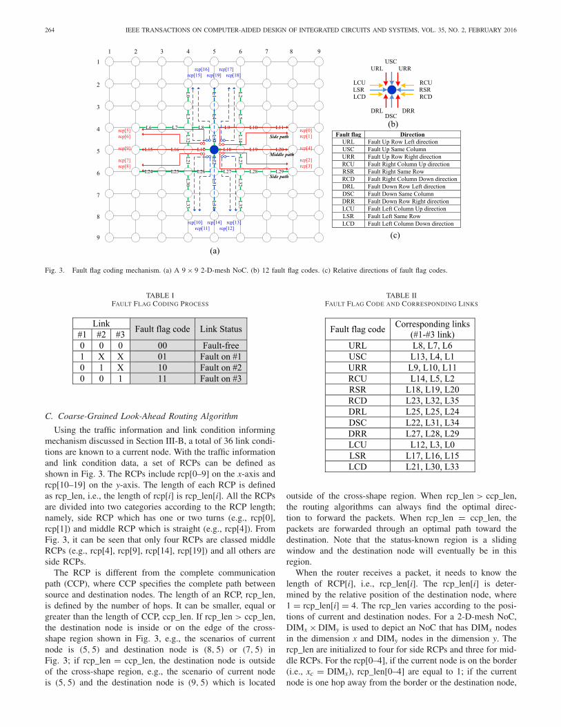
The corresponding name for the fault flag codes are pre-sented in Fig. 3(b). In total there are 12 different fault flagcodes which are named according to the directions. The rela-tive directions and full name of each fault flag code are shownin the table of Fig. 3(c), e.g., the term URL means the faultflag code in the up direction, location in a row, to the left
direction on that row. The term USC means the fault flagcode of the up direction in the same column. Fig. 3(a) isa 9 × 9 2-D-mesh NoC. There are 36 links labeled numerallyfrom link #0 (L0) up to link #35 (L35). The conditions ofthese links can be decoded by the 12 fault flag codes, i.e., theconditions of several links are represented by a fault flag code.The paths containing links of L0–L35 are defined as a regionalcommunication path (RCP), e.g., the path containing L13 andL9–L11 is defined as rcp[0]. All RCPs are bounded withinthe cross-shape regions depicted in Fig. 3. Fig. 3(a) showsexample RCPs, e.g., ranging from rcp[0] to rcp[19], withinthis bounding region. The bounding region is centered onthe current node containing the flit for transmission. As theflit is transmitted from node to node on its destination jour-ney, the cross-shape regions are also moved with the currentnode as the center of the regions, e.g., node (5, 5) as shownin Fig. 3.
A single bit value is used to represent a link condition of anRCP—e.g., “0” for fault-free and “1” for faulty. The overallcondition for an RCP (e.g., three links) is encoded to a two-bitfault flag code (see Table I). Based on this coding mechanism,the number of required physical connections to communicatea code can be reduced and the dynamic power can be mini-mized especially for the large-scale NoC system, as there are12 fault flag code connections for one node. For example, thelink conditions of L9–L11 in Fig. 3 are coded as fault flag in uprow right (URR) direction where the fault flag coding is basedon a link’s priority; e.g., the link which is closest to the cur-rent node is defined as #1 link and the furthest link is definedas #3. Therefore, L9–L11 are defined as #1–#3, respectively,for the URR code. Table I illustrates the coding process forthe fault status of the links. If all the links are fault-free, thefault flag code is “00.” If #1 link is faulty, the fault flag codeis “01.” In this scenario, the conditions of #2 and #3 linksare not important as #1 link is the closest path to the currentnode which has the highest priority. Similarly, the fault flagcode is “10” if the #1 link is fault-free, #2 link is faulty andthe condition of #3 is not important. If the links of #1, #2 arefault-free and #3 link is faulty, the fault flag code is “11.”
Every three link conditions are coded to one fault flagcode. The current node receives a total of 12 fault flagcodes which can be grouped into four directions—three faultflag codes per direction. For the north direction, the faultflag codes are URL, USC, and URR, where URL denotesthe fault flag code for the left direction at the up row andincludes the links conditions for L6–L8 links. Similarly forUSC and URR, the USC includes L1, L4, and L13 condi-tions and URR indicates the conditions of L9–L11 links. Thefault flag codes and their corresponding links are presentedin Table II, where the corresponding links are ranked by thepriority.
Decoding is the reverse of the fault flag coding process.After the current node receives the fault flag code, the condi-tions for #1–#3 links are decoded. Therefore, after receivingthe 12 fault flag codes, the current node [e.g., node (5, 5) inFig. 3] has knowledge of all the link conditions of L0–L35which provides key visibility of the fault-status in the regionand aids in making routing decisions.
264 IEEE TRANSACTIONS ON COMPUTER-AIDED DESIGN OF INTEGRATED CIRCUITS AND SYSTEMS, VOL. 35, NO. 2, FEBRUARY 2016
(a)
(b)
(c)
Fig. 3. Fault flag coding mechanism. (a) A 9 × 9 2-D-mesh NoC. (b) 12 fault flag codes. (c) Relative directions of fault flag codes.
TABLE IFAULT FLAG CODING PROCESS
C. Coarse-Grained Look-Ahead Routing Algorithm
Using the traffic information and link condition informingmechanism discussed in Section III-B, a total of 36 link condi-tions are known to a current node. With the traffic informationand link condition data, a set of RCPs can be defined asshown in Fig. 3. The RCPs include rcp[0–9] on the x-axis andrcp[10–19] on the y-axis. The length of each RCP is definedas rcp_len, i.e., the length of rcp[i] is rcp_len[i]. All the RCPsare divided into two categories according to the RCP length;namely, side RCP which has one or two turns (e.g., rcp[0],rcp[1]) and middle RCP which is straight (e.g., rcp[4]). FromFig. 3, it can be seen that only four RCPs are classed middleRCPs (e.g., rcp[4], rcp[9], rcp[14], rcp[19]) and all others areside RCPs.
The RCP is different from the complete communicationpath (CCP), where CCP specifies the complete path betweensource and destination nodes. The length of an RCP, rcp_len,is defined by the number of hops. It can be smaller, equal orgreater than the length of CCP, ccp_len. If rcp_len > ccp_len,the destination node is inside or on the edge of the cross-shape region shown in Fig. 3, e.g., the scenarios of currentnode is (5, 5) and destination node is (8, 5) or (7, 5) inFig. 3; if rcp_len = ccp_len, the destination node is outsideof the cross-shape region, e.g., the scenario of current nodeis (5, 5) and the destination node is (9, 5) which is located
TABLE IIFAULT FLAG CODE AND CORRESPONDING LINKS
outside of the cross-shape region. When rcp_len > ccp_len,the routing algorithms can always find the optimal direc-tion to forward the packets. When rcp_len = ccp_len, thepackets are forwarded through an optimal path toward thedestination. Note that the status-known region is a slidingwindow and the destination node will eventually be in thisregion.
When the router receives a packet, it needs to know thelength of RCP[i], i.e., rcp_len[i]. The rcp_len[i] is deter-mined by the relative position of the destination node, where1 = rcp_len[i] = 4. The rcp_len varies according to the posi-tions of current and destination nodes. For a 2-D-mesh NoC,DIMx × DIMy is used to depict an NoC that has DIMx nodesin the dimension x and DIMy nodes in the dimension y. Thercp_len are initialized to four for side RCPs and three for mid-dle RCPs. For the rcp[0–4], if the current node is on the border(i.e., xc = DIMx), rcp_len[0–4] are equal to 1; if the currentnode is one hop away from the border or the destination node,

LIU et al.: FAULT-TOLERANT NoC ROUTING WITH COARSE AND FG LOOK-AHEAD 265
TABLE IIIRCPs DIRECTION DEFINITION
rcp_len[0–3] are equal to 2 and rcp_len[4] is equal to 1; if thecurrent node is two hops away from the border or the des-tination node, rcp_len[0–3] are equal to 3 and rcp_len[4] isequal to 2. For all other scenarios, i.e., the current node isthree or more hops away from the border or destination node,rcp_len[0–3] are equal to an initial value of 4 and rcp_len[4]is equal to an initial value of 3. A similar path length calcula-tion process is applied to the rcp[5–19]. The rcp_len providesthe information of the number of links contained in a spe-cific path when a current node attempts to transmit packets toa destination node.
Based on the regional traffic conditions and the length ofRCPs, the RCP condition named rcp_con is used to indicatethe condition of the specific path rcp[i]. The rcp_con[i] canbe assessed using the following equation:
rcp_con[i] = link_con[1]|link_con[2]| · · · |link_con[rcp_len[i]] (2)
where rcp_con[i] is the condition for the rcp[i], link_con[1]is the link condition of the first link in the rcp[i],link_con[rcp_len[i]] is the link condition of the rcp_len[i]thlink and the operation is logical OR. If all the links ofRCP[i] are fault-free, then RCP[i] is fault-free. If one linkis faulty, RCP[i] is noted as being faulty. Therefore, this rout-ing approach is termed CG as it does not differentiate thecondition of the individual links in the path.
In the following section, the principle of the CG routingalgorithm is presented and the weight calculation mechanismis also detailed.
1) Priority Weighting of RCP Directions: The direction ofthe first link in an RCP defines the overall path direction asthe packet is forwarded to the next node via the selected link.All the RCPs and corresponding directions are presented inTable III. For example, the direction of rcp[5] is north as thedirection of first link, L13, is north. The directions of total20 RCPs are divided to four groups—N/E/S/W shown as inTable III.
The symbol wp[rcp[i]] denotes the priority weight value ofrcp[i] direction. The direction priority weight wp is determinedby the Q-value of this direction and PD level which wereillustrated in Section III-A. If the direction is PD1, the wp ofthis port is equal to 1; if it is PD2, wp = 2 and if it is PD3,wp = 3. For example, in Fig. 3 the current and destinationnodes are (5, 5) and (8, 5), therefore xd > xc and yd = yc.The destination node is in the D1 direction (D1 definition inFig. 1) and wp[N/E/S/W] = {2, 1, 2, 3}. The priority weightof rcp[5] is equal to wp[N], i.e., 2. It is a second preferredpath to transmit packets as the east direction is the first choice.Therefore, ideally a lower priority weight value is sought and
the direction with the lowest value is selected as the PD toroute the packets from the current node.
2) Busy and Congested Weighting of Immediate Link: Thetraffic status of the first link in the RCP (i.e., the immedi-ate connected link to the current node) is very important forthe routing decision making process. These traffic status sig-nals include busy, congestion, and faulty. Fig. 2 illustrates thatevery node in the system has the knowledge of the traffic sta-tus of the first links (neighbors) via dedicated busy/congestedinput signals which are generated based on the buffer of firstin first out (FIFO) occupancy of neighboring nodes.
The notation of sb and sc is used to denote the busy andcongested status of the first link. If the status of the link isbusy then sb = 1 and if the link is congested sc = 1. If thelink is not busy or congested then sb = sc = 0. The busyand congested statuses determine two corresponding weights;wlk1b and wlk1c. The weight values of wlk1b and wlk1c can becalculated using (3). It can be seen that the weight wlk1c isgiven precedence (i.e., wlk1c > wlk1b when sb = sc = 1)as the channel status of congested has the more significantperformance impact on a channel over busy
wlk1b ={
0, sb = 02, sb = 1
, wlk1c ={
0, sc = 03, sc = 1.
(3)
Each node connects to neighboring nodes via four immedi-ate links at the N/E/S/W directions. The notation of wlk1b[dir]and wlk1c[dir] are used to denote the weights at dir direc-tions where dir ∈ {N, E, S, W}. The weights of wlk1b[dir] andwlk1c[dir] reflect the traffic status of the immediate connectedlinks of a current node and will be used in the overall weightcalculation.
3) Faulty Weighting of the Direction: The fault weight,wf [dir], for direction dir is determined by the fault condi-tions of the various RCPs, rcp[i], in that dir direction. Ina 2-D mesh topology, the routing of packets can be forwardedvia north, east, south, or west directions. According to theforward directions for the next hop, the RCPs can be dividedinto four categories as illustrated in Table III. For example,if the direction for the next hop is north, packets from thecurrent node are forwarded through any one of the north direc-tion RCPs—rcp[5], rcp[16], rcp[17], rcp[19], or rcp[0]. Thesymbol of dir_con[dir] denotes the condition of the RCPs inthe direction dir for the current node (dir ∈ {N, E, S, W}),and is calculated by the logical expression of (4) as shownat the top of the next page, where rcp_con[i] is the con-dition of rcp[i] which is defined using (2). If any RCP inthis direction is fault-free (rcp_con[i] = 0), the condition ofthis direction is defined as fault-free, e.g., dir_con = 0; ifall the paths are faulty (rcp_con[i] = 1), the condition ofthis direction is defined as faulty; dir_con = 1. Equation (5)shows that the value of wf [dir] is determined by the con-ditions of the direction. If the direction is fault-free thenwf [dir] is equal to 0; if the direction is faulty, wf [dir] isequal to 10
wf [dir] ={
0, dir_con[dir] = 010, dir_con[dir] = 1.
(5)
The values of wlk1b/wlk1c/wf are calculated based on thefollowing rules: 1) the channel status of faulty has the most

266 IEEE TRANSACTIONS ON COMPUTER-AIDED DESIGN OF INTEGRATED CIRCUITS AND SYSTEMS, VOL. 35, NO. 2, FEBRUARY 2016
dir_con[North] = rcp_con[5] & rcp_con[16] & rcp_con[19] & rcp_con[17] & rcp_con[0]
dir_con[East] = rcp_con[1] & rcp_con[2] & rcp_con[4] & rcp_con[13] & rcp_con[18]
dir_con[South] = rcp_con[3] & rcp_con[12] & rcp_con[14] & rcp_con[11] & rcp_con[8]
dir_con[West] = rcp_con[7] & rcp_con[9] & rcp_con[6] & rcp_con[10] & rcpcon[15] (4)
significant performance impact on a channel, therefore thefaulty weight of the direction wf [dir] is greater than both pri-ority weight wp and busy/congested weights wlk1b and wlk1c;2) the channel status of congested has more performanceimpact on a channel, therefore the congested weight of thedirection wlk1c is greater than busy weights wlk1b; and 3) theweight value should be as small as possible to allow com-pact hardware implementation, therefore all the values arerepresented by four bits.
4) Total Weight of the Direction: All priority, busy/con-gested and fault weights are fed to a weight calculationmechanism which is used to select the ideal output direction.The total weight W[dir] for a direction, dir, is calculated using
W[dir] = wp[dir] + wlk1b[dir] + wlk1c[dir] + wf [dir] (6)
where W[dir] is the total weight for a single direction dir,wp[dir] is the weight for the direction priority, wlk1b is thebusy weight of the immediate link, wlk1c is the congestedweight of the immediate link and wf is the fault weight. Ifthe direction is faulty, wf = 10 which is sufficiently largeenough to choose a fault-free path, as the maximum sum-mary of other weights is 8. After the weight values of thefour directions are calculated, the direction with the small-est value is chosen as the PD to forward packets from thecurrent node.
The key advantages of the CG routing algorithm are: 1) ittolerates faults and can choose valid paths to bypass faultycomponents and 2) it can judge the distance to the destina-tion nodes to make optimal routing paths and avoid trafficstarvation or overload.
D. Fine-Grained Look-Ahead Routing Algorithm
The CG routing algorithm can make good routing pathdecisions to bypass faulty components however, it can onlydefine a complete RCP to be faulty and is unable to dif-ferentiate between the individual links in the RCP. The CGalgorithm is therefore suboptimal as a faulty link in an RCP,which is furthest away from a current node, could resultin the algorithm using an alternative routing path with anincreased latency overhead. The ability to know which partic-ular link is faulty in an RCP would lead to greater flexibilityin path selection and lower path latency. To improve uponthe granularity of fault sensing in a path, an FG routingalgorithm is proposed which weights each of the links inan RCP to differentiate between faulty and nonfaulty links.The FG algorithm calculates the weights for all of the 20 RCPsand selects the RCP with the lowest weight as the out-put path to forward the packets. Equation (7) illustrates
the weight of rcp[i] calculation process for the FG routingalgorithm
W[i] = wp[i] + wlk1b[i] + wlk1c[i] +rcp_len[i]∑
j=1
wf[j]
(7)
where 0 = i < 20, W[i] is the total weight for rcp[i], wp[i]is the direction priority of the rcp[i], wlk1b[i], and wlk1c[i] arethe busy and congested weights of first link in the rcp[i], andwf [j] is the fault weight of the jth link in the rcp[i] which isaccumulated from 1 to the RCP length. The weights of wp,wlk1b, and wlk1c can be calculated similarly as CG. The weightof wf [j] is the fault weight for the jth link in the RCP and isset to a value according to the position as expressed by{
wf [1, 2, 3, 4] = {10, 2, 2, 1}, if the path is a side pathwf [1, 2, 3] = {10, 4, 1}, if the path is a middle path
(8)
where wf [j] is set to be {10, 2, 2, 1} for the links sequen-tially in the side RCP as the maximal path length is 4, and{10, 4, 1} for the links sequentially in the middle RCP. Theweights are set in a decreased manner as the nearest link hasthe most significant impact for the path selection over a moredistant link.
In summary, compared to CG which does not differenti-ate the link conditions in the RCP (no visibility into whichlinks in the RCP are actually at fault), the FG approach givesa different weight to each link, calculates the weights for allthe 20 RCPs and finally chooses the best output path whichprovides the shortest option. For complex fault patterns, FGhas the analysis capability to look ahead in more detail (finerlevels within a path) to make better routing decisions. Thisultimately can reduce communication latency of packets andimprove system performance. This capability requires morearea overhead and therefore a detailed evaluation of CG andFG algorithms is presented in the following results section.
E. Deadlock and Livelock Avoidance
Duato’s theory [25], [26] is used to prove the deadlockand livelock freedom. The necessary definitions from Duato’stheory are included in the following text but the formal defi-nition can be found in [26]. An interconnection network I isa strongly connected directed multigraph, I = G(N, C). Thevertices N represent the set of router nodes. The arcs of C rep-resent the set of channels. The source and destination nodesof channel ci are denoted by si and di. An adaptive routingfunction R: N × N → (C), where (C) is the power setof C, supplies a set of alternative output channels of sendinga message from the current node nc to destination node nd,R(nc, nd) = c1, c2, . . . , cp. An R for a given I is connectediff, for any pair of nodes x, y ∈ N, it is possible to establish

LIU et al.: FAULT-TOLERANT NoC ROUTING WITH COARSE AND FG LOOK-AHEAD 267
a path P(x, y) ∈ (C) between them using channels belongingto the sets supplied by R. Given an R and a pair of adjacentchannels ci, cj ∈ C, there is a direct dependency from ci tocj if cj can be requested immediately after using ci by mes-sages destined for some node x. A channel dependency graphD for a given I and R is a directed graph, D = G(C, E). Thevertices of D are channels of I. The arcs of D are the pairof channels (ci, cj) such that there is a directed dependencyfrom ci to cj. Theorem 1 is proposed in [25], which is: anR for an I is deadlock-free iff there are no cycles in the D.Now, we give the related definitions regarding the CG and FGalgorithms as follows.
Definition 1: A single bypass path (SBP), PSBPc̃i
, of a singlefaulty physical channel c̃i in a given I, is a set of availablechannels to make a detour to avoid c̃i and forward the packetto nd (PSBP
c̃i⊂ C). For a given c̃i , there are several PSBP
c̃iwhich are ranked by the PD levels. There are two kinds ofSBPs—one is clockwise SBP (cSBP) where the packets aretransmitted through cSBP in a clockwise manner, the other isanticlockwise SBP (aSBP) where the packets are transmitted ina anticlockwise manner, e.g., in the bottom right part of Fig. 1,the upper PD2 is a cSBP and the lower PD2 is an aSBP.
In PSBPc̃i
, if other faulty channels exist which block PSBPc̃i
;then the path needs to be detoured again, i.e., more than oneSBP are required. These SBPs are combined together anddefined as a collective bypass path (CBP). A bypass path (BP)can be an SBP or CBP. The faulty channels are defined asa fault region (FR).
Definition 2: If a set of faulty channels F = {c̃1,c̃2, . . . , c̃n},for a given ∃(nc, nd) ∈ I, having {c2, c3, . . . , cn} ⊂ PSBP
c̃1,
or {c1, c3, . . . , cn} ⊂ PSBPc̃2
, . . . , or {c1, c2, . . . cn−1} ⊂ PSBPc̃n
;then the faulty channels form an FR. A CBP for a FR, PCBP
FR , isa set of channels PCBP
FR = {cp, cq, . . . , cz} to provide commu-nication from nc to nd, where sp = nc, dp = sq, . . . , dz = nd.Similar to SBP, CBP can be clockwise (cCBP) or anticlock-wise (aCBP).
Definition 3: Each physical channel is split into two virtualchannels, VC0 and VC1. Routing function supplies VC0 forthe PD1 direction. If the VC0 is blocked and unavailable, therouting function supplies VC1 for the BPs.
Definition 4: An FR is eligible if its BPs do not create cyclicdependencies between VCs.
Definition 5: More than one BPs are chained if they sharecommon channels. If the shared channels do not introducecyclic dependencies they are unlocked.
Theorem 2: The routing functions of CG and FG algorithmsare livelock free for a given I, if I is physically connected, andFR is convex or concave within a depth of three router hops.
Proof: The livelock freedom is discussed based on dif-ferent traffic statuses: 1) if the NoC is fault-free and notcongested, the CG and FG algorithms follow the dimension-order XY routing as PD1 is always chosen; therefore they arelivelock free; 2) for convex faulty regions, the CG and FGalgorithms route packets along the edge, then turn directionat the region corner and finally arrive at the destination node.For the concave faulty regions within a depth of three routerhops, the packets can avoid entering the faulty region as the
routing algorithms have a look-ahead function. For the set offaulty channels {c̃1,c̃2, . . . , c̃n}, the BP (SBP or CBP) sup-plies a communication path for any (nc, nd); therefore they arelivelock free; and 3) however, the system with other concavefaulty regions (e.g., larger than three hops depth) or seriousscenarios maybe introduce livelock. In order to avoid that,a node de-activation mechanism [27] or a rerouting constraintmechanism [17] can be employed. The former coverts the con-cave FR to be convex. The latter constrains the number ofrerouting performed and discards packets if rerouting exceedsa threshold number. �
Theorem 3: The routing functions of CG and FG algorithmsare deadlock free for a given I, if I is physically connectedand the FR is eligible or the faulty channels are isolated whoseBPs are unchained or unblocked chained.
Proof: Channel dependency graph and Duato’s Theorem 1are used to prove the routing functions of CG and FGare deadlock-free. According to Definition 3, channel depen-dency may occur between VC0 and VC1, or between VC1sof different BPs. For a given I, if the FR is eligible, orthe BPs of faulty channels are unchained or unblockedchained, the routing functions of CG and FG algorithms aredeadlock-free. �
Using VCs can avoid deadlock although it introduces hard-ware overhead. The VCs and control logic of CG, FG occupies27% and 25% of the router area, respectively.
F. Reaction Time of Fault Correction
The time between a fault occurrence until a failure is causedin the NoC is defined by fault causing failure time (τFCF).Similarly, the time between the fault occurrence until it hasbeen detected and diagnosed is defined as fault diagnosistime (τFDT); and the time until the correction action is trig-gered (e.g., packet path is updated by adaptive routing) isdefined as correction reaction time (τCRT). If τFDT + τCRT <
τFCF, it means that the fault has been diagnosed and cor-rection action has been triggered before the failure occurs;therefore the fault can be tolerated. However, for most ofcases, τFDT + τCRT = τFCF, i.e., the failure occurs before thecorrection action is triggered; therefore the fault is not toler-ated. There are two solutions for this problem—to increaseτFCF or to decrease the value of τFDT + τCRT. For the for-mer, several methods (e.g. error detecting/correcting code) canbe used to delay the failure occurrence. For the latter, faultdiagnosis and correction action should be completed promptlyafter fault occurs. In this paper, τFDT + τCRT is at least threeclock cycles. During this time window, packets are probablycorrupted and even worse affect the function of other nodes.Therefore, the time of τFDT+τCRT should be minimized, whichis the direction of future work.
IV. METHODOLOGY AND EXPERIMENTS RESULTS
This section outlines the methodology used in performingexperiments and obtaining results on the performance of theCG and FG algorithms under faulty and nonfaulty conditions.

268 IEEE TRANSACTIONS ON COMPUTER-AIDED DESIGN OF INTEGRATED CIRCUITS AND SYSTEMS, VOL. 35, NO. 2, FEBRUARY 2016
A. Performance Analysis Metrics and Experimental Platform
The performance metrics of throughput [7], T, is used anddefined in (9) where Rflits is the total number of received flits,Nnodes is the total number of nodes and Nclk is the numberof clocks cycles lapsed from the first generated flit to the lastreceived flit
T = Rflits
Nnodes × Nclk. (9)
Delay is defined as the number of clock cycles that elapsesbetween the occurrences of a header flit injection into the net-work from the source node until the occurrence of a tail flitreceived at the destination node. Equation (10) [7] defines theaverage delay, D, which is the average clock cycle value forthe total number of messages, where K is the total number ofmessages reaching their destination nodes and Di is the clockcycle delay for the ith node
D = 1/KK∑
i=1
Di. (10)
The simulator of Noxim [28] was extended to evaluatethe CG/FG routing algorithms’ performances. Similar tothe approach of [7], each simulation was initially run for1000 clock cycles to allow transient effects to stabilize and,subsequently was executed for 20 000 cycles. To guaranteethe accuracy of results, the simulation for each packet injec-tion rate (PIR) was repeated several times [7], [29]. PIR refersto the rate at which packets are injected into the NoC net-work. The normalized number of sent packets per clock cycleis equal to PIR and has the range 0 < PIR = 1. TheCG and FG routing algorithms are evaluated under varioussynthetic traffic patterns including: 1) uniform; 2) transpose;3) shuffle; 4) hot-spot, which are common traffic patternsused in evaluating routing performance [3], [7], [13], [14].In addition, two non-synthetic traffic loads of 5) matrixmultiplication and 6) multimedia system (MMS) are usedwhich are typical traffic loads of real-NoC applications,and have been used in other research as a testbenchframework [7], [9], [20], [30], [31]. The state-of-art fault-tolerant routing algorithms of fault-on-neighbour (FoN),Cost, FTDR, hierarchical fault-tolerant deflection rout-ing (FTDR-H) [20], Look-Ahead-Fault-Tolerant (LAFT),hybrid-look-ahead-fault-tolerant (HLAFT) [31] were com-pared against the CG and the FG algorithms.
B. Experimental Results
This section presents the results from experiments on theperformance of the CG and FG algorithms under varied trafficloads and compared against the listed benchmark algorithms.In this approach, the common fault, namely stuck-at [32], isconsidered as it is the most prevalent fault model for NoC andwas used in [33]. If packets pass through a channel experienc-ing a stuck-at fault, the RX router is not able to recognize thepackets as the channel is “stuck” at a logical level. A faultrate is used to represent the percentage of faulty links presentin an NoC system. An NoC system with varied fault rates(5%, 10%, 15% and 20%) was employed as the test benchframework for evaluating routing algorithm performance.
Fig. 4. Average throughput (bars) and average delay (lines) at different faultrates under various traffic patterns. (a) Uniform. (b) Transpose. (c) Shuffle.(d) Hotspot. (e) Matrix multiplication. (f) MMS.
They can provide a comprehensive analysis for the CG and FGalgorithms from low to high fault rates; and are also consistentwith [20] and [31]. The faults are injected to the NoC inter-connect using a fault injector [34]. Similar to [3] and [20], tenfault patterns are chosen for each fault rate and the averagevalue is used as the result.
Fig. 4 presents the throughput of the NoC system for theCG, FG routing algorithms under the six different traffic loads.The PIR below the saturation point is chosen. An NoC is sat-urated when an increase in applied load does not result ina linear increase in throughput. The benefit of using this PIRas the baseline value is that the throughputs are the same forthe fault-free NoC system (i.e., not in saturation); this allowsa fair evaluation of system performance under various faultylink percentages. When an NoC system has faulty links, thethroughput performance is degraded as the faulty links are notable to transmit packets. The throughput value for the differentfault rates (5%, 10%, 15% and 20%) using six various trafficpatterns are presented in Fig. 4. It can be seen that the CGand FG algorithms have different levels of throughput degrada-tion. Across all six traffic patterns, CG and FG algorithms hadan average throughput degradation between 1.25%–8.39% and0.71%–4.11%, respectively. The CG and FG algorithms main-tain system performance when the fault rate is lower than 15%.When the fault rate increases >15%, the throughput of CGonly experiences a marginal maximum degradation of 8.39%for a fault rate of 20%. Overall, compared to CG, FG achievesa much improved performance, i.e., only 4.11% maximumdegradation for rates of 20%. This is due to the fact that FGis able to choose the near-optimal path based on the FG look-ahead capability. In addition to the key metric of throughput,

LIU et al.: FAULT-TOLERANT NoC ROUTING WITH COARSE AND FG LOOK-AHEAD 269
TABLE IVTHROUGHPUT DEGRADATION AND AVERAGE DELAY INCREASE COMPARISON
BETWEEN FTDR, FTDR-H, CG, AND FG ROUTING ALGORITHMS
the communication latency is also used as a metric to evaluaterouting algorithm performance. Fig. 4 also presents the aver-age delay at different fault rates with various traffic patterns.When the fault rate increases, the average delays increase, i.e.,it takes a longer time for a packet to arrive at the destinationnode. For CG and FG routers, the average delays increasebut the throughputs almost remain at the same level (at faultrates of 5%–15%) or have a marginal decrease (at fault rateof 20%), i.e., CG and FG require a longer time to forward thepackets to arrive at the destination nodes. Note: FG achievesa better performance than CG as it forwards more flits anddoes so within a shorter time period.
Several state of the art fault-tolerant routing algorithmsin [20] and [31], namely FoN, cost, FTDR, FTDR-H, LAFTand HLAFT, are chosen as benchmarks in evaluating theCG and FG performance. The throughput degradation andaverage delay increase are chosen as the benchmark metricsfor all of the routing algorithms to allow a fair compar-ison of system performance. No single testbench platformis standard however, the throughput degradation and aver-age delay increase can reflect the fault-tolerant capabilitiesof the routing algorithms. Traffic loads of uniform, trans-pose, shuffle, and matrix multiplication, and fault rates at5%, 10%, and 20% are chosen as the testbench baseline, aswere done in [20] and [31]. Table IV presents the through-put degradation and average delay increase results. FoN,Cost, FTDR, and FTDR-H have 28%–70% throughput degra-dation under fault rates between 10%–20%. CG and FGalgorithms have a significantly lower throughput degrada-tion of ∼10% at fault rates between 10%–20% compared toFoN, Cost, FTDR, and FTDR-H. The fault tolerance capabil-ity of HLAFT is better than LAFT [31], where HLAFT has0.9%–54% throughput degradation under fault rates 5%–20%.CG and FG only have 0.18%–9.61% throughput degradation,
i.e., outperforming HLAFT. This demonstrates the ability ofCG and FG in tolerating faults in the NoC system andhow they can minimize throughput degradation when faultsoccur. As the benchmark routings use various metrics torecord the communication latency, the average delay increaseis employed to evaluate the communication latency perfor-mance. Average delay increase reflects the degree of additionaltime required for packets to arrive at the destination nodeswhen faults occur. It is defined as the delay increment per-centage at a specific fault rate compared to the fault-freestatus, e.g., for uniform traffic pattern, the average delaysof CG is 13.28 and 14.15 clock cycles at fault rates of 0%and 5%, respectively; therefore the average delay increase is6.55% [i.e., (14.15 − 13.28)/13.28 = 6.55%]. Table IV illus-trates that for all six traffic patterns, algorithms FoN, Cost,FTDR, and FTDR-H have 50%–442% average delay increasesunder fault rates of between 10%–20%. LAFT and HLAFThave 11%–333% average delay increases under fault rates ofbetween 5%–20%. CG and FG have an average delay increaseof 4%–296% under the same conditions. The average delaytrending increase of CG and FG is the same as the benchmarkrouting algorithms. However, CG and FG achieve a lower aver-age delay increase in most scenarios. Note—they also havea higher increment in several scenarios. This occurs becausethe packets are forwarded across longer alternative paths, how-ever, the corresponding throughput degradation is not high,i.e., the throughput performance is maintained as demonstratedin the top half of Table IV.
From the aforementioned performance results, it can be seenthat CG and FG algorithms have marginal performance degra-dation for the varied fault rates across the different trafficpatterns. The CG routing algorithm considers the whole pathto be faulty if only one link in the path is compromised andis unable to identify the faulty link position. The FG routing

270 IEEE TRANSACTIONS ON COMPUTER-AIDED DESIGN OF INTEGRATED CIRCUITS AND SYSTEMS, VOL. 35, NO. 2, FEBRUARY 2016
algorithm differentiates the links and sets different weight val-ues for them in the path. Therefore, FG algorithm has bettervisibility in the location of the faulty link and thus can makenear-optimal decisions, which is better than CG algorithm.On the other hand, the CG algorithm has a compact hard-ware overhead compared to FG algorithm due to the simplifiedcomputing process. The next section will discuss the hardwarearea overhead for CG and FG algorithms.
V. HARDWARE IMPLEMENTATION
This section presents the methodology for implement-ing the CG and FG routing algorithms in hardware andalso presents an evaluation of the inherent area overheadand power consumption. The hardware evaluation processfollowed the standard ASIC cell design flow, synthesis,and verification based on a Synopsys Armenia EducationalDepartment (SAED) 90 nm CMOS technology using theSynopsys Design Compiler tool.
A. Hardware Implementation of CG and FG
Fig. 5(a) shows the schematic of a single emulatingbiologically-inspired architectures on hardware (EMBRACE)router [9] implementing the CG and FG ARSs. The top levelscheme of the router consists of an input buffer (FIFO), MM,ARS (CG or FG), and adaptive arbitration policy (AAP) com-ponents. When a router attempts to send or forward a packet,the routing module checks the traffic status of all the channelsand decides which port is the best way to forward the packet.This routing decision is made by choosing the lowest weightof all the ports and follows three steps: 1) check the trafficinformation of the total 36 links; 2) calculate the weights forevery direction/RCP; and 3) compare the weights and choosethe direction/RCP with the lowest weight. Fig. 5(b) presentsthe weight calculating and selection mechanism of the CF/FGstructure. It should be noted that CG routing compares theweight of each direction and selects the direction W[dir] withthe lowest weight. Therefore the number of weights to be com-pared for CG algorithm is 4, i.e., the four directions N/E/S/W.However, FG algorithm compares the weights for 20 RCPs andselects the RCP with the lowest weight. Therefore, the numberof candidates for FG algorithm is 20 (finer level of informa-tion to make a decision). The weight computing unit structurefor every candidate is shown in Fig. 5(c). Upon completionof all the weight calculations, they are added together to gen-erate the overall weight for the direction or RCP—W[dir] orW[rcp]. Finally, all the weights are fed to the weight compara-tor which compares the input weight values and selects the onewith the lowest weight as the most appropriate output port,i.e., direction. Moreover, Fig. 6 shows the area utilizationsof the proposed CG and FG routers including the area over-head of all the modules—net interconnect, input FIFO, faultflag coding/decoding, MM, AAP, output register, and CG/FGrouting modules. The router areas of CG and FG algorithmsare 237 115 and 267 756 μm2 where the area overheads ofCG/FG routing modules are 10.98% and 21.15%, respectively.Although the area overhead of FG algorithm is greater thanCG algorithm, the fault-tolerant capability of FG algorithm ismuch stronger, e.g., it provides a higher throughput (9%) than
CG algorithm at 20% fault rate under transpose traffic pattern,as shown in Fig. 4.
B. Performance Analysis
1) Router Area: Table V illustrates the router capabilitiesand hardware area of the benchmark routers. The approachesin [10] and [11] have a fault-tolerant capability, but theycannot detect the interconnect faults and do not have thecongestion-aware capability. The router areas for both are68 000 μm2 and 185 392 μm2, respectively. The routingalgorithms FoN, Cost, FTDR, and FTDR-H [20] have thecapabilities of fault detection, congestion awareness and faulttolerance. The FTDR and FTDR-H outperforms the FoNand cost routings in respect of fault-tolerant capability [20].The corresponding area for each NoC router implementa-tions of FoN, Cost, FTDR, and FTDR-H are 39 076, 82 277,101 754, and 74 323 μm2, respectively; based on TaiwanSemiconductor Manufacturing Company (TSMC) 65 nm tech-nology. If error control coding (ECC) modules are included,the area overheads of the FTDR router using two differentECC strategies are 163 712 and 158 950 μm2, respectively.To make a comparison between the 90 and 65 nm nodetechnology implementations, we can use a first order scal-ing factor to evaluate CG and FG routers at 65 nm. Forexample, the area of an NAND 2 × 1 gate is 1.44 μm2 forTSMC 65 nm and 5.5296 μm2 for SAED 90 nm [35], there-fore a first order scaling parameter, δ = 1.44/5.5296, canbe used to convert the area occupied using 90 to 65 nmnode. The first order 65 nm area calculations for the CGand FG routers are defined as 237 115 ∗ δ = 61748.698 μm2
and 267 756 * δ = 69 728.125 μm2 which are smaller thanFTDR-H (74 323 μm2 without ECC) [20]. The approachesLAFT and HLAFT [31] are used for 3-D NoC systems whichhave the capabilities of congestion-aware and fault-tolerant.Their area range between 3134 and 4580 configurable logicblocks (ALUTs) based on Altera FPGA technology. Notethat the benchmarks of [10], [11], [20], and [31] use differentrouter architectures and therefore the router area compari-son is not appropriate for a fair evaluation. The approachesof [4], [24], and this paper are based on the same architecturewhich enables a more balanced comparison. The approachin [4] provides congestion-aware adaptive routing withouta fault-tolerant capability, therefore the router area is rela-tive low (56 000 μm2). Based on [4], the router in [24] wasextended with MM modules to provide a level of fault detec-tion capability which increased the area (182 076 μm2). Whileimplementing CG and FG fault-tolerant routing algorithms, therouter area is increased further. As expected, as more routercapabilities are added more hardware area is consumed.
2) Operating Frequency Analysis: The maximum operatingfrequency of baseline [24], CG and FG routers are 245 210 and200 MHz, respectively. The frequency of CG and FG routersdecreases due to the routing algorithms computation process.However, CG and FG routers have much better fault-tolerantcapabilities than the baseline router [24]. Similar to NoC sys-tems such as SpiNNaker [36] and EMBRACE [4], [37], a lowsystem clock frequency of 100 MHz is chosen in this paper, asthis paper targets the embedded systems domain. In addition,

LIU et al.: FAULT-TOLERANT NoC ROUTING WITH COARSE AND FG LOOK-AHEAD 271
(a) (b) (c)
Fig. 5. CG and FG routing scheme structure. (a) One node of the NoC system. (b) CG/FG routing scheme structure. (c) Weight computing unit structure.
Fig. 6. Synthesis summary regarding the area utilization distributions of the proposed CG and FG routers.
TABLE VROUTER CAPABILITY AND HARDWARE AREA
the fault flag propagating path is not a critical path as the faultflag does not need to be propagated within one clock cycle.Fault flag coding and decoding are based on three links [seeFig. 3(c) and Table II]. They are implemented by a simplecombinational logic circuit. A multicycle path timing con-straint is set for the fault flag propagating. There is no timingviolation if a multicycle of 2 is set, i.e., the current node cansense the traffic status from distant routers within two clockcycles. The MM in [24] is used in this paper. It can detectthe faults of immediate connected links (i.e., L13, L17, L18,and L22) in one clock cycle. The router can also make correctrouting decisions within two clock cycles, which is analyzedbased on two different fault types.
a) Permanent Faults: The CG and FG router architecturesare similar to a five-stage NoC router [38]. After a faultoccurs, at most one packet is forwarded to a nonoptimal
path with a faulty link in the distant router. However,in the next hop, the router will sense the link conditionchange and forward this packet to a fault-free path.
b) Transient Faults: The transient faults only last for sev-eral clock cycles [20]. If it occurs in a distant router,when the packet arrives there, the fault has disappeared;if it occurs in a neighboring router, the packet will beforwarded to a fault-free path as the MM can detectthe fault immediately. Therefore, the fault flag propagat-ing does not affect the critical path delay and operatingfrequency.
3) Power Consumption: The hardware evaluation processalso followed an FPGA design flow based on the Stratix IVEP4SGX530KH40C2 using Quartus II software. Altera’sPowerPlay Power Analysis tool was also used to analyzepower dissipation. An 8 × 8 NoC system under various
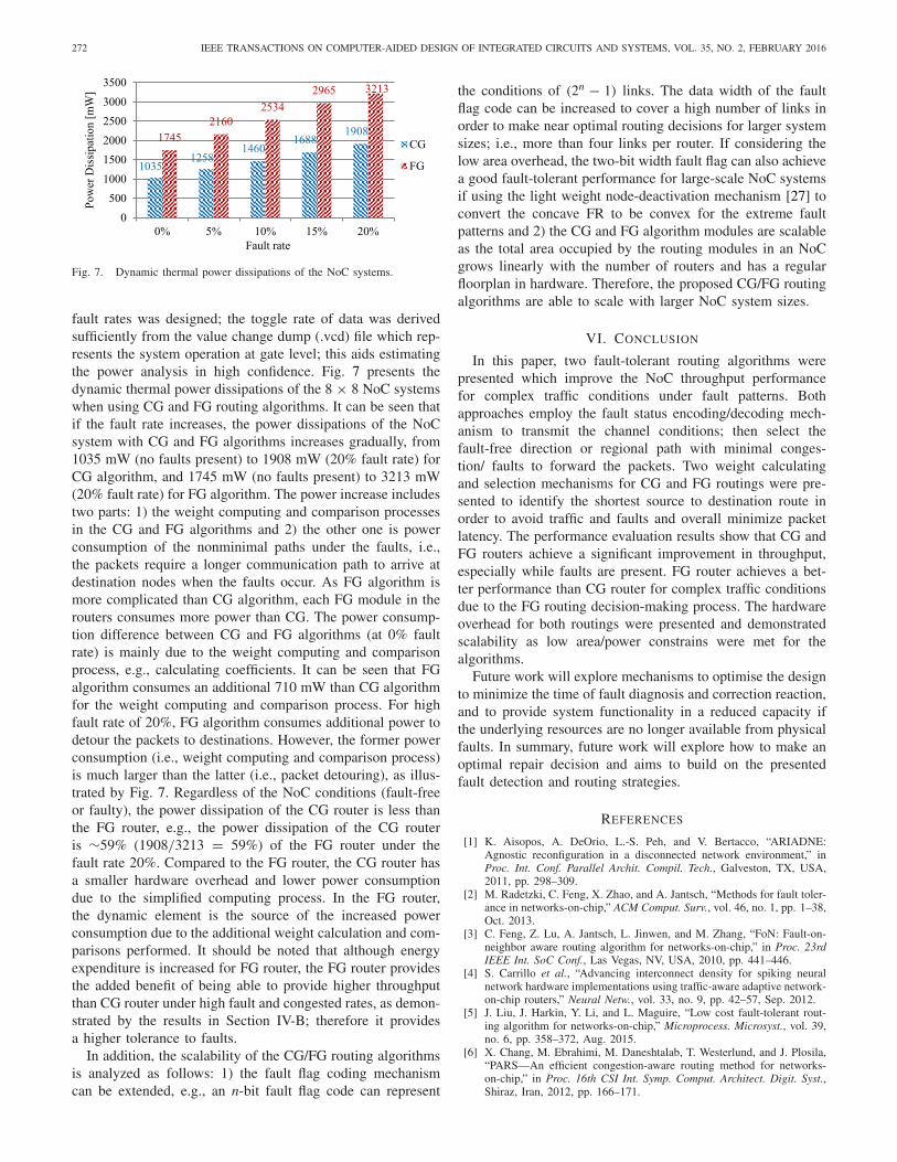
272 IEEE TRANSACTIONS ON COMPUTER-AIDED DESIGN OF INTEGRATED CIRCUITS AND SYSTEMS, VOL. 35, NO. 2, FEBRUARY 2016
Fig. 7. Dynamic thermal power dissipations of the NoC systems.
fault rates was designed; the toggle rate of data was derivedsufficiently from the value change dump (.vcd) file which rep-resents the system operation at gate level; this aids estimatingthe power analysis in high confidence. Fig. 7 presents thedynamic thermal power dissipations of the 8 × 8 NoC systemswhen using CG and FG routing algorithms. It can be seen thatif the fault rate increases, the power dissipations of the NoCsystem with CG and FG algorithms increases gradually, from1035 mW (no faults present) to 1908 mW (20% fault rate) forCG algorithm, and 1745 mW (no faults present) to 3213 mW(20% fault rate) for FG algorithm. The power increase includestwo parts: 1) the weight computing and comparison processesin the CG and FG algorithms and 2) the other one is powerconsumption of the nonminimal paths under the faults, i.e.,the packets require a longer communication path to arrive atdestination nodes when the faults occur. As FG algorithm ismore complicated than CG algorithm, each FG module in therouters consumes more power than CG. The power consump-tion difference between CG and FG algorithms (at 0% faultrate) is mainly due to the weight computing and comparisonprocess, e.g., calculating coefficients. It can be seen that FGalgorithm consumes an additional 710 mW than CG algorithmfor the weight computing and comparison process. For highfault rate of 20%, FG algorithm consumes additional power todetour the packets to destinations. However, the former powerconsumption (i.e., weight computing and comparison process)is much larger than the latter (i.e., packet detouring), as illus-trated by Fig. 7. Regardless of the NoC conditions (fault-freeor faulty), the power dissipation of the CG router is less thanthe FG router, e.g., the power dissipation of the CG routeris ∼59% (1908/3213 = 59%) of the FG router under thefault rate 20%. Compared to the FG router, the CG router hasa smaller hardware overhead and lower power consumptiondue to the simplified computing process. In the FG router,the dynamic element is the source of the increased powerconsumption due to the additional weight calculation and com-parisons performed. It should be noted that although energyexpenditure is increased for FG router, the FG router providesthe added benefit of being able to provide higher throughputthan CG router under high fault and congested rates, as demon-strated by the results in Section IV-B; therefore it providesa higher tolerance to faults.
In addition, the scalability of the CG/FG routing algorithmsis analyzed as follows: 1) the fault flag coding mechanismcan be extended, e.g., an n-bit fault flag code can represent
the conditions of (2n − 1) links. The data width of the faultflag code can be increased to cover a high number of links inorder to make near optimal routing decisions for larger systemsizes; i.e., more than four links per router. If considering thelow area overhead, the two-bit width fault flag can also achievea good fault-tolerant performance for large-scale NoC systemsif using the light weight node-deactivation mechanism [27] toconvert the concave FR to be convex for the extreme faultpatterns and 2) the CG and FG algorithm modules are scalableas the total area occupied by the routing modules in an NoCgrows linearly with the number of routers and has a regularfloorplan in hardware. Therefore, the proposed CG/FG routingalgorithms are able to scale with larger NoC system sizes.
VI. CONCLUSION
In this paper, two fault-tolerant routing algorithms werepresented which improve the NoC throughput performancefor complex traffic conditions under fault patterns. Bothapproaches employ the fault status encoding/decoding mech-anism to transmit the channel conditions; then select thefault-free direction or regional path with minimal conges-tion/ faults to forward the packets. Two weight calculatingand selection mechanisms for CG and FG routings were pre-sented to identify the shortest source to destination route inorder to avoid traffic and faults and overall minimize packetlatency. The performance evaluation results show that CG andFG routers achieve a significant improvement in throughput,especially while faults are present. FG router achieves a bet-ter performance than CG router for complex traffic conditionsdue to the FG routing decision-making process. The hardwareoverhead for both routings were presented and demonstratedscalability as low area/power constrains were met for thealgorithms.
Future work will explore mechanisms to optimise the designto minimize the time of fault diagnosis and correction reaction,and to provide system functionality in a reduced capacity ifthe underlying resources are no longer available from physicalfaults. In summary, future work will explore how to make anoptimal repair decision and aims to build on the presentedfault detection and routing strategies.
REFERENCES
[1] K. Aisopos, A. DeOrio, L.-S. Peh, and V. Bertacco, “ARIADNE:Agnostic reconfiguration in a disconnected network environment,” inProc. Int. Conf. Parallel Archit. Compil. Tech., Galveston, TX, USA,2011, pp. 298–309.
[2] M. Radetzki, C. Feng, X. Zhao, and A. Jantsch, “Methods for fault toler-ance in networks-on-chip,” ACM Comput. Surv., vol. 46, no. 1, pp. 1–38,Oct. 2013.
[3] C. Feng, Z. Lu, A. Jantsch, L. Jinwen, and M. Zhang, “FoN: Fault-on-neighbor aware routing algorithm for networks-on-chip,” in Proc. 23rdIEEE Int. SoC Conf., Las Vegas, NV, USA, 2010, pp. 441–446.
[4] S. Carrillo et al., “Advancing interconnect density for spiking neuralnetwork hardware implementations using traffic-aware adaptive network-on-chip routers,” Neural Netw., vol. 33, no. 9, pp. 42–57, Sep. 2012.
[5] J. Liu, J. Harkin, Y. Li, and L. Maguire, “Low cost fault-tolerant rout-ing algorithm for networks-on-chip,” Microprocess. Microsyst., vol. 39,no. 6, pp. 358–372, Aug. 2015.
[6] X. Chang, M. Ebrahimi, M. Daneshtalab, T. Westerlund, and J. Plosila,“PARS—An efficient congestion-aware routing method for networks-on-chip,” in Proc. 16th CSI Int. Symp. Comput. Architect. Digit. Syst.,Shiraz, Iran, 2012, pp. 166–171.

LIU et al.: FAULT-TOLERANT NoC ROUTING WITH COARSE AND FG LOOK-AHEAD 273
[7] G. Ascia, V. Catania, M. Palesi, and D. Patti, “Implementation and analy-sis of a new selection strategy for adaptive routing in networks-on-chip,”IEEE Trans. Comput., vol. 57, no. 6, pp. 809–820, Jun. 2008.
[8] B. Niazmand, M. Reshadi, and A. Reza, “PathAware: A contention-aware selection function for application-specific network-on-chips,” inProc. NORCHIP, Copenhagen, Denmark, 2012, pp. 1–6.
[9] P.-A. Tsai, Y.-H. Kuo, E.-J. Chang, H.-K. Hsin, and A.-Y. Wu, “Hybridpath-diversity-aware adaptive routing with latency prediction model innetwork-on-chip systems,” in Proc. Int. Symp. VLSI Design Autom.Test (VLSI-DAT), Hsinchu, Taiwan, 2013, pp. 1–4.
[10] Z. Zhang, A. Greiner, and S. Taktak, “A reconfigurable routing algorithmfor a fault-tolerant 2D-mesh network-on-chip,” in Proc. 45th IEEE/ACEDesign Autom. Conf., Anaheim, CA, USA, 2008, pp. 441–446.
[11] J. Wang, F. Fu, T. Zhang, and Y. Chen, “A small-granularity solution onfault-tolerant in 2D-mesh network-on-chip,” in Proc. 10th IEEE Conf.Solid-State Integr. Circuit Technol., Shanghai, China, 2010, pp. 382–384.
[12] M. Ali, M. Welzl, S. Hessler, and S. Hellebrand, “A fault tolerant mech-anism for handling permanent and transient failures in a network onchip,” in Proc. 4th Int. Conf. Inf. Technol., Las Vegas, NV, USA, 2007,pp. 1027–1032.
[13] I. Pratomo and S. Pillement, “Gradient—An adaptive fault-tolerant rout-ing algorithm for 2D mesh network-on-chips,” in Proc. Design Archit.Signal Image Process. (DASIP), Karlsruhe, Germany, 2012, pp. 1–8.
[14] P. Lotfi-Kamran, A. M. Rahmani, M. Daneshtalab, A. Afzali-Kusha,and Z. Navabi, “EDXY—A low cost congestion-aware routing algo-rithm for network-on-chips,” J. Syst. Archit., vol. 56, no. 7, pp. 256–264,Jul. 2010.
[15] A. Vitkovskiy, V. Soteriou, and C. Nicopoulos, “Dynamic fault-tolerantrouting algorithm for networks-on-chip based on localised detouringpaths,” IET Comput. Digit. Tech., vol. 7, no. 2, pp. 93–103, Mar. 2013.
[16] M. Ebrahimi, M. Daneshtalab, and J. Plosila, “High performance fault-tolerant routing algorithm for NoC-based many-core systems,” in Proc.21st Int. Conf. Parallel Distrib. Netw.-Based Process., Belfast, U.K.,2013, pp. 462–469.
[17] A. Alhussien, C. Wang, and N. Bagherzadeh, “Design and evaluationof a high throughput robust router for network-on-chip,” IET Comput.Digit. Tech., vol. 6, no. 3, pp. 173–179, May 2012.
[18] A. Mehranzadeh, A. Khademzadeh, and A. Mehran, “FADyAD—Faultand congestion aware routing algorithm based on DyAD algorithm,” inProc. 5th Int. Symp. Telecommun., Tehran, Iran, 2010, pp. 274–279.
[19] M. Dimopoulos et al., “Fault-tolerant adaptive routing under permanentand temporary failures for many-core systems-on-chip,” in Proc. IEEE19th Int. On-Line Test. Symp. (IOLTS), Chania, Greece, 2013, pp. 7–12.
[20] C. Feng, Z. Lu, A. Jantsch, M. Zhang, and Z. Xing, “Addressing tran-sient and permanent faults in NoC with efficient fault-tolerant deflectionrouter,” IEEE Trans. Very Large Scale Integr. (VLSI) Syst., vol. 21, no. 6,pp. 1053–1066, Jun. 2013.
[21] S. Rodrigo et al., “Addressing manufacturing challenges with cost-efficient fault tolerant routing,” in Proc. 4th ACM/IEEE Int. Symp. Netw.Chip, Grenoble, France, 2010, pp. 25–32.
[22] J. Flich, A. Mejia, P. Lopez, and J. Duato, “Region-based routing: Anefficient routing mechanism to tackle unreliable hardware in network onchips,” in Proc. ACM/IEEE Int. Symp. Netw. Chip, Princeton, NJ, USA,2007, pp. 183–194.
[23] F. Chaix, D. Avresky, N.-E. Zergainoh, and M. Nicolaidis, “A fault-tolerant deadlock-free adaptive routing for on chip interconnects,” inProc. Design Autom. Test Europe Conf. Exhibit. (DATE), Grenoble,France, 2011, pp. 1–4.
[24] J. Liu, J. Harkin, Y. Li, and L. Maguire, “Online traffic-aware faultdetection for networks-on-chip,” J. Parallel Distrib. Comput., vol. 74,no. 1, pp. 1984–1993, Jan. 2014.
[25] J. Duato, S. Yalamanchili, and L. Ni, Interconnection Networks: AnEngineering Approach. San Francisco, CA, USA: Morgan Kaufmann,2003.
[26] J. Duato, “A theory of fault-tolerant routing in wormhole networks,”IEEE Trans. Parallel Distrib. Syst., vol. 8, no. 8, pp. 790–802,Aug. 1997.
[27] A. A. Chien and J. H. Kim, “Planar-adaptive routing: Low-cost adap-tive networks for multiprocessors,” J. ACM, vol. 42, no. 1, pp. 91–123,Jan. 1995.
[28] M. Palesi, D. Patti, and F. Fazzino. (2010). Noxim: Network-on-Chip Simulator. [Online]. Available: http://www.noxim.org, accessed onJun. 2013.
[29] A. Mejia et al., “Region-based routing: A mechanism to support effi-cient routing algorithms in NoCs,” IEEE Trans. Very Large ScaleIntegr. (VLSI) Syst., vol. 17, no. 3, pp. 356–369, Mar. 2009.
[30] Y.-H. Kuo et al., “Path-diversity-aware adaptive routing in network-on-chip systems,” in Proc. IEEE 6th Int. Symp. Embed. Multicore SoCs,Aizuwakamatsu, Japan, 2012, pp. 175–182.
[31] A. B. Ahmed and A. B. Abdallah, “Graceful deadlock-free fault-tolerantrouting algorithm for 3D network-on-chip architectures,” J. ParallelDistrib. Comput., vol. 74, no. 4, pp. 2229–2240, Apr. 2014.
[32] C. Michael, D. Sujit, B. Xiaoliang, and Z. Yi, “Fault modeling andsimulation for crosstalk in system-on-chip interconnects,” in Proc.IEEE/ACM Int. Conf. Comput.-Aided Design, San Jose, CA, USA, 1999,pp. 297–303.
[33] C. Grecu and A. Ivanov, “Testing network-on-chip communicationfabrics,” IEEE Trans. Comput.-Aided Design Integr. Circuits Syst.,vol. 26, no. 12, pp. 2201–2214, Dec. 2007.
[34] M. Birner and T. Handl, “ARROW—A generic hardware fault injectiontool for NoCs,” in Proc. 12th Euromicro Conf. Digit. Syst. Design Archit.Methods Tools, Patras, Greece, Aug. 2009, pp. 465–472.
[35] SAED EDK90 Core Digital Standard Cell Library, Synopsys, MountainView, CA, USA, 2009, pp. 1–102.
[36] S. B. Furber et al., “Overview of the SpiNNaker system architecture,”IEEE Trans. Comput., vol. 62, no. 12, pp. 2454–2467, Dec. 2013.
[37] S. Carrillo et al., “Scalable hierarchical network-on-chip architecture forspiking neural network hardware implementations,” IEEE Trans. ParallelDistrib. Syst., vol. 24, no. 12, pp. 2451–2461, Dec. 2013.
[38] N. E. Jerger and L.-S. Peh, On-Chip Networks, vol. 4. San Rafael, CA,USA: Morgan and Claypool, 2009.
Junxiu Liu (S’04) is currently pursuing the Ph.D.degree in computer science with the University ofUlster, Derry, U.K., by the help from the Vice-Chancellor’s Research Scholarship.
His current research interests include system andnetworks-on-chip and embedded systems.
Jim Harkin received the B.Tech. degree in elec-tronic engineering, the M.Sc. degree in electronicsand signal processing, and the Ph.D. degree inembedded systems from the University of Ulster,Derry, U.K., in 1996, 1997, and 2001, respectively.
He is a Senior Lecturer with the School ofComputing and Intelligent Systems, University ofUlster. His current research interests include designof intelligent embedded systems to support self-repairing capabilities and the hardware/softwareimplementation of spiking neural networks. He has
published over 80 articles in peer-reviewed journals and conferences.
Yuhua Li (SM’05) received the Ph.D. degreein general engineering from the University ofLeicester, Leicester, U.K., in 2003.
He was a Senior Research Fellow withManchester Metropolitan University, Manchester,U.K., and a Research Associate with the Universityof Manchester, Manchester, from 2000 to 2005. Hewas a Lecturer with the School of Computing andIntelligent Systems, University of Ulster, Derry,U.K., from 2005 to 2014. He is currently a Lecturerwith the School of Computing, Science and
Engineering, University of Salford, Manchester, U.K. His current researchinterests include pattern recognition, machine learning, knowledge-basedsystems, data science, and condition monitoring and fault diagnosis.
Liam P. Maguire received the M.Eng. and Ph.D.degrees in electrical and electronic engineering fromthe Queen’s University of Belfast, Belfast, U.K., in1988 and 1991, respectively.
He is currently the Dean of the Faculty ofComputing and Engineering and the Director ofthe Intelligent Systems Research Centre, Universityof Ulster, Derry, U.K. His current research inter-ests include fundamental research in bio-inspiredintelligent systems and the application of existingintelligent techniques in different domains. He has
authored over 200 research papers including 70 journal papers. He has anestablished track record of securing research funding and has also supervised15 Ph.D. and three M.Phil. students to completion.