25mm CUTMASTER - Rapid Welding 25 Service Manual.pdf · CUTMASTER 25mm GENERAL INFORMATION 2 Manual...
116
Art # A-08803_AB 380V 400V 415V PLASMA CUTTING SYSTEM 25mm CUTMASTER ™ Rev. AB Date: May 29, 2009 Manual # 0-5081 Operating Features: Service Manual
Transcript of 25mm CUTMASTER - Rapid Welding 25 Service Manual.pdf · CUTMASTER 25mm GENERAL INFORMATION 2 Manual...

Art # A-08803_AB
380V400V415V
PLASMA CUTTING SYSTEM
25mmCUTMASTER™
Rev. AB Date: May 29, 2009 Manual # 0-5081Operating Features:
Service Manual

WE APPRECIATE YOUR BUSINESS!
Congratulations on your new Thermal Dynamics product. We are proud to have you as our customer and will strive to provide you with the best service and reliability in the industry. This product is backed by our extensive warranty and world-wide service network. To locate your nearest distributor or service agency call 1-800-426-1888, or visit us on the web at www.thermal-dynamics.com.
This Operating Manual has been designed to instruct you on the correct use and operation of your Thermal Dynamics product. Your satisfaction with this product and its safe operation is our ultimate concern. Therefore please take the time to read the entire manual, especially the Safety Precautions. They will help you to avoid po-tential hazards that may exist when working with this product.
YOU ARE IN GOOD COMPANY!
The Brand of Choice for Contractors and Fabricators Worldwide.Thermal Dynamics is a Global Brand of manual and automation Plasma Cutting Products for Thermadyne Industries Inc.
We distinguish ourselves from our competition through market-leading, dependable products that have stood the test of time. We pride ourselves on technical innovation, competitive prices, excellent delivery, superior customer service and technical support, together with excellence in sales and marketing expertise.
Above all, we are committed to developing technologically ad-vanced products to achieve a safer working environment within the welding industry.
! WARNINGS
Read and understand this entire Manual and your employer’s safety practices before installing, operat-ing, or servicing the equipment.
While the information contained in this Manual represents the Manufacturer's best judgement, the Manufacturer assumes no liability for its use.
Plasma Cutting Power SupplyCutMaster™ 25mmSL60 1Torch™Service Manual Number 0-5081
Published by:Thermal Dynamics Corporation82 Benning StreetWest Lebanon, New Hampshire, USA 03784(603) 298-5711
www.thermal-dynamics.com
Copyright 2009 byThermadyne Corporation
All rights reserved.
Reproduction of this work, in whole or in part, without written permission of the publisher is prohibited.
The publisher does not assume and hereby disclaims any liability to any party for any loss or damage caused by any error or omission in this Manual, whether such error results from negligence, accident, or any other cause.
Printed in the United States of America
Original Publication Date: January 9, 2009Revision Date: May 29, 2009
Record the following information for Warranty purposes:
Where Purchased:_______________________________ ________________
Purchase Date:__________________________________ ________________
Power Supply Serial #:___________________________ ________________
Torch Serial #:___________________________________ ________________
i

This Page Intentionally Blank
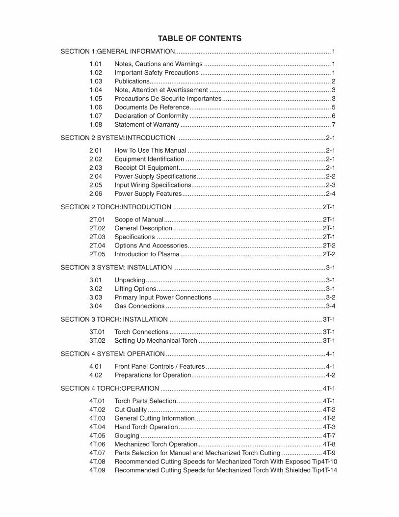
TABLE OF CONTENTS
SECTION 1:GENERAL INFORMATION ...................................................................................... 1
1.01 Notes, Cautions and Warnings ...................................................................... 11.02 Important Safety Precautions ........................................................................ 11.03 Publications.................................................................................................... 21.04 Note, Attention et Avertissement ................................................................... 31.05 Precautions De Securite Importantes ............................................................ 31.06 Documents De Reference .............................................................................. 51.07 Declaration of Conformity .............................................................................. 61.08 Statement of Warranty ................................................................................... 7
SECTION 2 SYSTEM:INTRODUCTION .................................................................................2-1
2.01 How To Use This Manual ............................................................................2-12.02 Equipment Identification .............................................................................2-12.03 Receipt Of Equipment .................................................................................2-12.04 Power Supply Specifications .......................................................................2-22.05 Input Wiring Specifications ..........................................................................2-32.06 Power Supply Features ...............................................................................2-4
SECTION 2 TORCH:INTRODUCTION .................................................................................. 2T-1
2T.01 Scope of Manual ....................................................................................... 2T-12T.02 General Description .................................................................................. 2T-12T.03 Specifications ........................................................................................... 2T-12T.04 Options And Accessories .......................................................................... 2T-22T.05 Introduction to Plasma .............................................................................. 2T-2
SECTION 3 SYSTEM: INSTALLATION ...................................................................................3-1
3.01 Unpacking ...................................................................................................3-13.02 Lifting Options .............................................................................................3-13.03 Primary Input Power Connections ..............................................................3-23.04 Gas Connections ........................................................................................3-4
SECTION 3 TORCH: INSTALLATION .................................................................................... 3T-1
3T.01 Torch Connections .................................................................................... 3T-13T.02 Setting Up Mechanical Torch .................................................................... 3T-1
SECTION 4 SYSTEM: OPERATION ........................................................................................4-1
4.01 Front Panel Controls / Features ..................................................................4-14.02 Preparations for Operation ..........................................................................4-2
SECTION 4 TORCH:OPERATION ......................................................................................... 4T-1
4T.01 Torch Parts Selection ................................................................................ 4T-14T.02 Cut Quality ................................................................................................ 4T-24T.03 General Cutting Information ...................................................................... 4T-24T.04 Hand Torch Operation ............................................................................... 4T-34T.05 Gouging .................................................................................................... 4T-74T.06 Mechanized Torch Operation .................................................................... 4T-84T.07 Parts Selection for Manual and Mechanized Torch Cutting ...................... 4T-94T.08 Recommended Cutting Speeds for Mechanized Torch With Exposed Tip 4T-104T.09 Recommended Cutting Speeds for Mechanized Torch With Shielded Tip 4T-14
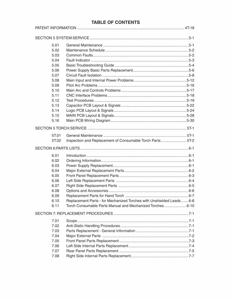
TABLE OF CONTENTSPATENT INFORMATION ...................................................................................................... 4T-18
SECTION 5 SYSTEM:SERVICE ..............................................................................................5-1
5.01 General Maintenance .................................................................................5-15.02 Maintenance Schedule ...............................................................................5-25.03 Common Faults ...........................................................................................5-25.04 Fault Indicator .............................................................................................5-35.05 Basic Troubleshooting Guide ......................................................................5-45.06 Power Supply Basic Parts Replacement.....................................................5-65.07 Circuit Fault Isolation ..................................................................................5-85.08 Main Input and Internal Power Problems ..................................................5-125.09 Pilot Arc Problems ....................................................................................5-165.10 Main Arc and Controls Problems ..............................................................5-175.11 CNC Interface Problems ...........................................................................5-185.12 Test Procedures ........................................................................................5-195.13 Capacitor PCB Layout & Signals ..............................................................5-225.14 Logic PCB Layout & Signals .....................................................................5-245.15 MAIN PCB Layout & Signals .....................................................................5-285.16 Main PCB Wiring Diagram ........................................................................5-30
SECTION 5 TORCH:SERVICE .............................................................................................. 5T-1
5T.01 General Maintenance ............................................................................... 5T-15T.02 Inspection and Replacement of Consumable Torch Parts ........................ 5T-2
SECTION 6:PARTS LISTS .......................................................................................................6-1
6.01 Introduction .................................................................................................6-16.02 Ordering Information ...................................................................................6-16.03 Power Supply Replacement ........................................................................6-16.04 Major External Replacement Parts .............................................................6-26.05 Front Panel Replacement Parts ..................................................................6-36.06 Left Side Replacement Parts .....................................................................6-46.07 Right Side Replacement Parts ...................................................................6-56.08 Options and Accessories ............................................................................6-66.09 Replacement Parts for Hand Torch ............................................................6-76.10 Replacement Parts - for Mechanized Torches with Unshielded Leads .......6-86.11 Torch Consumable Parts Manual and Mechanized Torches .....................6-10
SECTION 7: REPLACEMENT PROCEDURES .......................................................................7-1
7.01 Scope ..........................................................................................................7-17.02 Anti-Static Handling Procedures .................................................................7-17.03 Parts Replacement - General Information ..................................................7-17.04 Major External Parts ..................................................................................7-27.05 Front Panel Parts Replacement ..................................................................7-37.06 Left Side Internal Parts Replacement .........................................................7-47.07 Rear Panel Parts Replacement ..................................................................7-57.08 Right Side Internal Parts Replacement .......................................................7-7
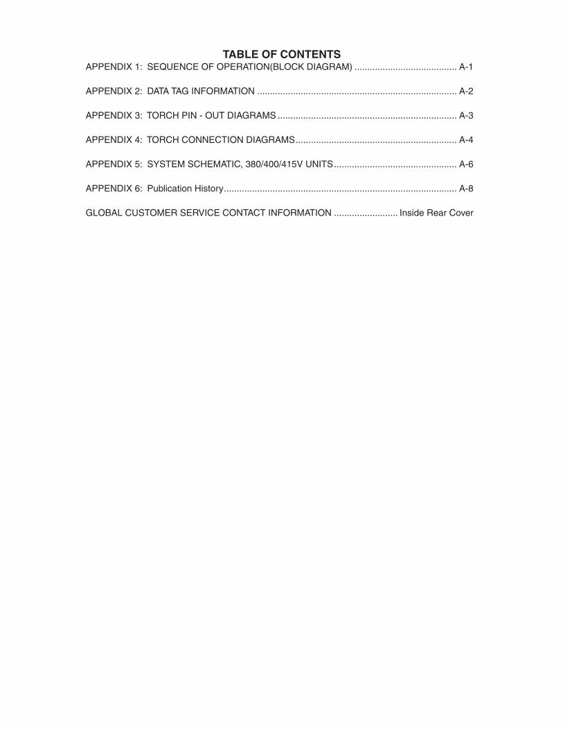
TABLE OF CONTENTSAPPENDIX 1: SEQUENCE OF OPERATION(BLOCK DIAGRAM) ........................................ A-1
APPENDIX 2: DATA TAG INFORMATION .............................................................................. A-2
APPENDIX 3: TORCH PIN - OUT DIAGRAMS ...................................................................... A-3
APPENDIX 4: TORCH CONNECTION DIAGRAMS ............................................................... A-4
APPENDIX 5: SYSTEM SCHEMATIC, 380/400/415V UNITS ................................................ A-6
APPENDIX 6: Publication History ........................................................................................... A-8
GLOBAL CUSTOMER SERVICE CONTACT INFORMATION ......................... Inside Rear Cover

TABLE OF CONTENTS
CUTMASTER 25mm
Manual 0-5081 1 GENERAL INFORMATION
SECTION 1: GENERAL INFORMATION
1.01 Notes, Cautions and Warnings
Throughout this manual, notes, cautions, and warnings are used to highlight important information. These highlights are categorized as follows:
NOTE
An operation, procedure, or background information which requires additional emphasis or is helpful in ef-ficient operation of the system.
CAUTION
A procedure which, if not properly followed, may cause damage to the equipment.
!WARNING
A procedure which, if not properly followed, may cause injury to the operator or others in the operating area.
1.02 Important Safety Precautions
WARNINGS
OPERATION AND MAINTENANCE OF PLASMA ARC EQUIPMENT CAN BE DANGEROUS AND HAZARDOUS TO YOUR HEALTH.
Plasma arc cutting produces intense electric and magnetic emissions that may interfere with the proper function of cardiac pacemakers, hearing aids, or other electronic health equipment. Persons who work near plasma arc cutting applications should consult their medical health professional and the manufacturer of the health equipment to determine whether a hazard exists.
To prevent possible injury, read, understand and follow all warnings, safety precautions and instructions before using the equipment. Call 1-603-298-5711 or your local distributor if you have any questions.
GASES AND FUMES
Gases and fumes produced during the plasma cutting process can be dangerous and hazardous to your health.
• Keep all fumes and gases from the breathing area. Keep your head out of the welding fume plume.
• Use an air-supplied respirator if ventilation is not adequate to remove all fumes and gases.
• The kinds of fumes and gases from the plasma arc depend on the kind of metal being used, coatings on the metal, and the different processes. You must be very careful when cutting or welding any metals which may contain one or more of the following:
Antimony Chromium Mercury Arsenic Cobalt Nickel Barium Copper Selenium Beryllium Lead Silver Cadmium Manganese Vanadium
• Always read the Material Safety Data Sheets (MSDS) that should be supplied with the material you are using. These MSDSs will give you the information regarding the kind and amount of fumes and gases that may be dangerous to your health.
• For information on how to test for fumes and gases in your workplace, refer to item 1 in Subsection 1.03, Publications in this manual.
• Use special equipment, such as water or down draft cutting tables, to capture fumes and gases.
• Do not use the plasma torch in an area where combustible or explosive gases or materials are located.
• Phosgene, a toxic gas, is generated from the vapors of chlo-rinated solvents and cleansers. Remove all sources of these vapors.
• This product, when used for welding or cutting, produces fumes or gases which contain chemicals known to the State of California to cause birth defects and, in some cases, cancer. (California Health & Safety Code Sec. 25249.5 et seq.)
ELECTRIC SHOCK
Electric Shock can injure or kill. The plasma arc process uses and produces high voltage electrical energy. This electric energy can cause severe or fatal shock to the operator or others in the workplace.
• Never touch any parts that are electrically “live” or “hot.”
• Wear dry gloves and clothing. Insulate yourself from the work piece or other parts of the welding circuit.
• Repair or replace all worn or damaged parts.
• Extra care must be taken when the workplace is moist or damp.
• Install and maintain equipment according to NEC code, refer to item 9 in Subsection 1.03, Publications.
• Disconnect power source before performing any service or repairs.
• Read and follow all the instructions in the Operating Manual.
FIRE AND EXPLOSION
Fire and explosion can be caused by hot slag, sparks, or the plasma arc.
• Be sure there is no combustible or flammable material in the workplace. Any material that cannot be removed must be protected.
• Ventilate all flammable or explosive vapors from the work-place.
CUTMASTER 25mm
GENERAL INFORMATION 2 Manual 0-5081
• Do not cut or weld on containers that may have held combus-tibles.
• Provide a fire watch when working in an area where fire hazards may exist.
• Hydrogen gas may be formed and trapped under aluminum workpieces when they are cut underwater or while using a water table. DO NOT cut aluminum alloys underwater or on a water table unless the hydrogen gas can be eliminated or dissipated. Trapped hydrogen gas that is ignited will cause an explosion.
NOISE
Noise can cause permanent hearing loss. Plasma arc processes can cause noise levels to exceed safe limits. You must protect your ears from loud noise to prevent permanent loss of hearing.
• To protect your hearing from loud noise, wear protective ear plugs and/or ear muffs. Protect others in the workplace.
• Noise levels should be measured to be sure the decibels (sound) do not exceed safe levels.
• For information on how to test for noise, see item 1 in Subsec-tion 1.03, Publications, in this manual.
PLASMA ARC RAYS
Plasma Arc Rays can injure your eyes and burn your skin. The plasma arc process produces very bright ultra violet and infra red light. These arc rays will damage your eyes and burn your skin if you are not properly protected.
• To protect your eyes, always wear a welding helmet or shield. Also always wear safety glasses with side shields, goggles or other protective eye wear.
• Wear welding gloves and suitable clothing to protect your skin from the arc rays and sparks.
• Keep helmet and safety glasses in good condition. Replace lenses when cracked, chipped or dirty.
• Protect others in the work area from the arc rays. Use protective booths, screens or shields.
• Use the shade of lens as suggested in the following per ANSI/ASC Z49.1:
Minimum Protective Suggested Arc Current Shade No. Shade No.
Less Than 300* 8 9
300 - 400* 9 12
400 - 800* 10 14
* These values apply where the actual arc is clearly seen. Experience has shown that lighter filters may be used when the arc is hidden by the workpiece.
LEAD WARNING
This product contains chemicals, including lead, or otherwise produces chemicals known to the State of California to cause cancer, birth defects and other reproductive harm. Wash hands after handling. (California Health & Safety Code § 25249.5 et seq.)
1.03 Publications
Refer to the following standards or their latest revisions for more information:
1. OSHA, SAFETY AND HEALTH STANDARDS, 29CFR 1910, obtainable from the Superintendent of Documents, U.S. Government Printing Office, Washington, D.C. 20402
2. ANSI Standard Z49.1, SAFETY IN WELDING AND CUTTING, obtainable from the American Welding Society, 550 N.W. LeJeune Rd, Miami, FL 33126
3. NIOSH, SAFETY AND HEALTH IN ARC WELDING AND GAS WELDING AND CUTTING, obtainable from the Superintendent of Documents, U.S. Government Printing Office, Washington, D.C. 20402
4. ANSI Standard Z87.1, SAFE PRACTICES FOR OCCUPATION AND EDUCATIONAL EYE AND FACE PROTECTION, obtainable from American National Standards Institute, 1430 Broadway, New York, NY 10018
5. ANSI Standard Z41.1, STANDARD FOR MEN’S SAFETY-TOE FOOTWEAR, obtainable from the American National Standards Institute, 1430 Broadway, New York, NY 10018
6. ANSI Standard Z49.2, FIRE PREVENTION IN THE USE OF CUT-TING AND WELDING PROCESSES, obtainable from American National Standards Institute, 1430 Broadway, New York, NY 10018
7. AWS Standard A6.0, WELDING AND CUTTING CONTAIN-ERS WHICH HAVE HELD COMBUSTIBLES, obtainable from American Welding Society, 550 N.W. LeJeune Rd, Miami, FL 33126
8. NFPA Standard 51, OXYGEN-FUEL GAS SYSTEMS FOR WELDING, CUTTING AND ALLIED PROCESSES, obtainable from the National Fire Protection Association, Batterymarch Park, Quincy, MA 02269
9. NFPA Standard 70, NATIONAL ELECTRICAL CODE, obtainable from the National Fire Protection Association, Batterymarch Park, Quincy, MA 02269
10. NFPA Standard 51B, CUTTING AND WELDING PROCESSES, obtainable from the National Fire Protection Association, Batterymarch Park, Quincy, MA 02269
11. CGA Pamphlet P-1, SAFE HANDLING OF COMPRESSED GASES IN CYLINDERS, obtainable from the Compressed Gas Association, 1235 Jefferson Davis Highway, Suite 501, Arlington, VA 22202
12. CSA Standard W117.2, CODE FOR SAFETY IN WELDING AND CUTTING, obtainable from the Canadian Standards As-sociation, Standards Sales, 178 Rexdale Boulevard, Rexdale, Ontario, Canada M9W 1R3
13. NWSA booklet, WELDING SAFETY BIBLIOGRAPHY obtainable from the National Welding Supply Association, 1900 Arch Street, Philadelphia, PA 19103
CUTMASTER 25mm
Manual 0-5081 3 GENERAL INFORMATION
14. American Welding Society Standard AWSF4.1, RECOM-MENDED SAFE PRACTICES FOR THE PREPARATION FOR WELDING AND CUTTING OF CONTAINERS AND PIPING THAT HAVE HELD HAZARDOUS SUBSTANCES, obtainable from the American Welding Society, 550 N.W. LeJeune Rd, Miami, FL 33126
15. ANSI Standard Z88.2, PRACTICE FOR RESPIRATORY PRO-TECTION, obtainable from American National Standards Institute, 1430 Broadway, New York, NY 10018
1.04 Note, Attention et Avertissement
Dans ce manuel, les mots “note,” “attention,” et “avertissement” sont utilisés pour mettre en relief des informations à caractère important. Ces mises en relief sont classifiées comme suit :
NOTE
Toute opération, procédure ou renseignement général sur lequel il importe d’insister davantage ou qui contribue à l’efficacité de fonctionnement du système.
ATTENTION
Toute procédure pouvant résulter l’endommagement du matériel en cas de non-respect de la procédure en question.
!AVERTISSEMENT
Toute procédure pouvant provoquer des blessures de l’opérateur ou des autres personnes se trouvant dans la zone de travail en cas de non-respect de la procédure en question.
1.05 Precautions De Securite Importantes
AVERTISSEMENTS
L’OPÉRATION ET LA MAINTENANCE DU MATÉRIEL DE SOUDAGE À L’ARC AU JET DE PLASMA PEUVENT PRÉSENTER DES RISQUES ET DES DANGERS DE SANTÉ.
Coupant à l’arc au jet de plasma produit de l’énergie électrique haute tension et des émissions magnétique qui peuvent interférer la fonction propre d’un “pacemaker” cardiaque, les appareils auditif, ou autre matériel de santé electronique. Ceux qui travail près d’une application à l’arc au jet de plasma devrait consulter leur membre pro-fessionel de médication et le manufacturier de matériel de santé pour déterminer s’il existe des risques de santé.
Il faut communiquer aux opérateurs et au personnel TOUS les dangers possibles. Afin d’éviter les blessures possibles, lisez, comprenez et suivez tous les avertisse-ments, toutes les précautions de sécurité et toutes les consignes avant d’utiliser le matériel. Composez le + 603-298-5711 ou votre distributeur local si vous avez des questions.
FUMÉE et GAZ
La fumée et les gaz produits par le procédé de jet de plasma peuvent présenter des risques et des dangers de santé.
• Eloignez toute fumée et gaz de votre zone de respiration. Gardez votre tête hors de la plume de fumée provenant du chalumeau.
• Utilisez un appareil respiratoire à alimentation en air si l’aération fournie ne permet pas d’éliminer la fumée et les gaz.
• Les sortes de gaz et de fumée provenant de l’arc de plasma dépen-dent du genre de métal utilisé, des revêtements se trouvant sur le métal et des différents procédés. Vous devez prendre soin lorsque vous coupez ou soudez tout métal pouvant contenir un ou plusieurs des éléments suivants:
antimoine cadmium mercure argent chrome nickel arsenic cobalt plomb baryum cuivre sélénium béryllium manganèse vanadium
• Lisez toujours les fiches de données sur la sécurité des matières (sigle américain “MSDS”); celles-ci devraient être fournies avec le matériel que vous utilisez. Les MSDS contiennent des renseigne-ments quant à la quantité et la nature de la fumée et des gaz pouvant poser des dangers de santé.
• Pour des informations sur la manière de tester la fumée et les gaz de votre lieu de travail, consultez l’article 1 et les documents cités à la page 5.
• Utilisez un équipement spécial tel que des tables de coupe à débit d’eau ou à courant descendant pour capter la fumée et les gaz.
• N’utilisez pas le chalumeau au jet de plasma dans une zone où se trouvent des matières ou des gaz combustibles ou explosifs.
• Le phosgène, un gaz toxique, est généré par la fumée provenant des solvants et des produits de nettoyage chlorés. Eliminez toute source de telle fumée.
• Ce produit, dans le procéder de soudage et de coupe, produit de la fumée ou des gaz pouvant contenir des éléments reconnu dans L’état de la Californie, qui peuvent causer des défauts de naissance et le cancer. (La sécurité de santé en Californie et la code sécurité Sec. 25249.5 et seq.)
CHOC ELECTRIQUE
Les chocs électriques peuvent blesser ou même tuer. Le procédé au jet de plasma requiert et produit de l’énergie électrique haute tension. Cette énergie électrique peut produire des chocs graves, voire mortels, pour l’opérateur et les autres personnes sur le lieu de travail.
• Ne touchez jamais une pièce “sous tension” ou “vive”; portez des gants et des vêtements secs. Isolez-vous de la pièce de travail ou des autres parties du circuit de soudage.
• Réparez ou remplacez toute pièce usée ou endommagée.
• Prenez des soins particuliers lorsque la zone de travail est humide ou moite.
CUTMASTER 25mm
GENERAL INFORMATION 4 Manual 0-5081
• Montez et maintenez le matériel conformément au Code électrique national des Etats-Unis. (Voir la page 5, article 9.)
• Débranchez l’alimentation électrique avant tout travail d’entretien ou de réparation.
• Lisez et respectez toutes les consignes du Manuel de consignes.
INCENDIE ET EXPLOSION
Les incendies et les explosions peuvent résulter des scories chaudes, des étincelles ou de l’arc de plasma. Le procédé à l’arc de plasma produit du métal, des étincelles, des scories chaudes pouvant mettre le feu aux matières combustibles ou provoquer l’explosion de fumées inflammables.
• Soyez certain qu’aucune matière combustible ou inflammable ne se trouve sur le lieu de travail. Protégez toute telle matière qu’il est impossible de retirer de la zone de travail.
• Procurez une bonne aération de toutes les fumées inflammables ou explosives.
• Ne coupez pas et ne soudez pas les conteneurs ayant pu renfermer des matières combustibles.
• Prévoyez une veille d’incendie lors de tout travail dans une zone présentant des dangers d’incendie.
• Le gas hydrogène peut se former ou s’accumuler sous les pièces de travail en aluminium lorsqu’elles sont coupées sous l’eau ou sur une table d’eau. NE PAS couper les alliages en aluminium sous l’eau ou sur une table d’eau à moins que le gas hydrogène peut s’échapper ou se dissiper. Le gas hydrogène accumulé explosera si enflammé.
RAYONS D’ARC DE PLASMA
Les rayons provenant de l’arc de plasma peuvent blesser vos yeux et brûler votre peau. Le procédé à l’arc de plasma produit une lumière infra-rouge et des rayons ultra-violets très forts. Ces rayons d’arc nuiront à vos yeux et brûleront votre peau si vous ne vous protégez pas correctement.
• Pour protéger vos yeux, portez toujours un casque ou un écran de soudeur. Portez toujours des lunettes de sécurité munies de parois latérales ou des lunettes de protection ou une autre sorte de protection oculaire.
• Portez des gants de soudeur et un vêtement protecteur approprié pour protéger votre peau contre les étincelles et les rayons de l’arc.
• Maintenez votre casque et vos lunettes de protection en bon état. Remplacez toute lentille sale ou comportant fissure ou rognure.
• Protégez les autres personnes se trouvant sur la zone de travail contre les rayons de l’arc en fournissant des cabines ou des écrans de protection.
• Utilisez la nuance de lentille qui est suggèrée dans le recommenda-tion qui suivent ANSI/ASC Z49.1:
Nuance Minimum Nuance Suggerée Courant Arc Protective Numéro Numéro
Moins de 300* 8 9
300 - 400* 9 12
400 - 800* 10 14
* Ces valeurs s’appliquent ou l’arc actuel est observé clairement. L’experience a démontrer que les filtres moins foncés peuvent être utilisés quand l’arc est caché par moiceau de travail.
BRUIT
Le bruit peut provoquer une perte permanente de l’ouïe. Les procédés de soudage à l’arc de plasma peuvent provoquer des niveaux sonores supérieurs aux limites normalement acceptables. Vous dú4ez vous protéger les oreilles contre les bruits forts afin d’éviter une perte permanente de l’ouïe.
• Pour protéger votre ouïe contre les bruits forts, portez des tampons protecteurs et/ou des protections auriculaires. Protégez également les autres personnes se trouvant sur le lieu de travail.
• Il faut mesurer les niveaux sonores afin d’assurer que les décibels (le bruit) ne dépassent pas les niveaux sûrs.
• Pour des renseignements sur la manière de tester le bruit, consultez l’article 1, page 5.
PLOMB AVERTISSEMENT
Ce produit contient des produits chimiques, comme le plomb, ou engendre des produits chimiques, reconnus par l’état de Californie comme pouvant être à l’origine de cancer, de mal-formations fœtales ou d’autres problèmes de reproduction. I l faut se laver les mains après toute manipulation. (Code de Californie de la sécurité et santé, paragraphe 25249.5 et suivants)
CUTMASTER 25mm
Manual 0-5081 5 GENERAL INFORMATION
1.06 Documents De Reference
Consultez les normes suivantes ou les révisions les plus récentes ayant été faites à celles-ci pour de plus amples renseignements :
1. OSHA, NORMES DE SÉCURITÉ DU TRAVAIL ET DE PROTECTION DE LA SANTÉ, 29CFR 1910, disponible auprès du Superintendent of Documents, U.S. Government Printing Office, Washington, D.C. 20402
2. Norme ANSI Z49.1, LA SÉCURITÉ DES OPÉRATIONS DE COUPE ET DE SOUDAGE, disponible auprès de la Société Américaine de Soudage (American Welding Society), 550 N.W. LeJeune Rd., Miami, FL 33126
3. NIOSH, LA SÉCURITÉ ET LA SANTÉ LORS DES OPÉRATIONS DE COUPE ET DE SOUDAGE À L’ARC ET AU GAZ, disponible auprès du Superintendent of Documents, U.S. Government Printing Office, Washington, D.C. 20402
4. Norme ANSI Z87.1, PRATIQUES SURES POUR LA PROTECTION DES YEUX ET DU VISAGE AU TRAVAIL ET DANS LES ECOLES, disponible de l’Institut Américain des Normes Nationales (Ameri-can National Standards Institute), 1430 Broadway, New York, NY 10018
5. Norme ANSI Z41.1, NORMES POUR LES CHAUSSURES PRO-TECTRICES, disponible auprès de l’American National Standards Institute, 1430 Broadway, New York, NY 10018
6. Norme ANSI Z49.2, PRÉVENTION DES INCENDIES LORS DE L’EMPLOI DE PROCÉDÉS DE COUPE ET DE SOUDAGE, disponible auprès de l’American National Standards Institute, 1430 Broadway, New York, NY 10018
7. Norme A6.0 de l’Association Américaine du Soudage (AWS), LE SOUDAGE ET LA COUPE DE CONTENEURS AYANT RENFERMÉ DES PRODUITS COMBUSTIBLES, disponible auprès de la American Welding Society, 550 N.W. LeJeune Rd., Miami, FL 33126
8. Norme 51 de l’Association Américaine pour la Protection contre les Incendies (NFPA), LES SYSTEMES À GAZ AVEC ALIMENTATION EN OXYGENE POUR LE SOUDAGE, LA COUPE ET LES PROCÉDÉS ASSOCIÉS, disponible auprès de la National Fire Protection As-sociation, Batterymarch Park, Quincy, MA 02269
9. Norme 70 de la NFPA, CODE ELECTRIQUE NATIONAL, disponible auprès de la National Fire Protection Association, Batterymarch Park, Quincy, MA 02269
10. Norme 51B de la NFPA, LES PROCÉDÉS DE COUPE ET DE SOUD-AGE, disponible auprès de la National Fire Protection Association, Batterymarch Park, Quincy, MA 02269
11. Brochure GCA P-1, LA MANIPULATION SANS RISQUE DES GAZ COMPRIMÉS EN CYLINDRES, disponible auprès de l’Association des Gaz Comprimés (Compressed Gas Association), 1235 Jefferson Davis Highway, Suite 501, Arlington, VA 22202
12. Norme CSA W117.2, CODE DE SÉCURITÉ POUR LE SOUDAGE ET LA COUPE, disponible auprès de l’Association des Normes Canadiennes, Standards Sales, 178 Rexdale Boulevard, Rexdale, Ontario, Canada, M9W 1R3
13. Livret NWSA, BIBLIOGRAPHIE SUR LA SÉCURITÉ DU SOUDAGE, disponible auprès de l’Association Nationale de Fournitures de Soudage (National Welding Supply Association), 1900 Arch Street, Philadelphia, PA 19103
14. Norme AWSF4.1 de l’Association Américaine de Soudage, RECOM-MANDATIONS DE PRATIQUES SURES POUR LA PRÉPARATION À LA COUPE ET AU SOUDAGE DE CONTENEURS ET TUYAUX AYANT RENFERMÉ DES PRODUITS DANGEREUX , disponible auprès de la American Welding Society, 550 N.W. LeJeune Rd., Miami, FL 33126
15. Norme ANSI Z88.2, PRATIQUES DE PROTECTION RESPIRATOIRE, disponible auprès de l’American National Standards Institute, 1430 Broadway, New York, NY 10018

CUTMASTER 25mm
GENERAL INFORMATION 6 Manual 0-5081
1.07 Declaration of ConformityManufacturer: Thermal Dynamics CorporationAddress: 82 Benning Street West Lebanon, New Hampshire 03784 USA
The equipment described in this manual conforms to all applicable aspects and regulations of the ‘Low Voltage Directive’ (2006/95 EC) and to the National legislation for the enforcement of this Directive.
The equipment described in this manual conforms to all applicable aspects and regulations of the "EMC Directive" (European Council Directive 89/336/EEC) and to the National legislation for the enforcement of this Directive.
Serial numbers are unique with each individual piece of equipment and details description, parts used to manufacture a unit and date of manufacture.
National Standard and Technical Specifications
The product is designed and manufactured to a number of standards and technical requirements. Among them are:
* CSA (Canadian Standards Association) standard C22.2 number 60 for Arc welding equipment.
* UL (Underwriters Laboratory) rating 94VO flammability testing for all printed-circuit boards used.
* CENELEC EN50199 EMC Product Standard for Arc Welding Equipment.
* ISO/IEC 60974-1 (BS 638-PT10) (EN 60 974-1) (EN50192) (EN50078) applicable to plasma cutting equipment and associated accessories.
* For environments with increased hazard of electrical shock, Power Supplies bearing the 'S' mark conform to EN50192 when used in conjunction with hand torches with exposed cutting tips, if equipped with properly installed standoff guides.
* Extensive product design verification is conducted at the manufacturing facility as part of the routine design and manufacturing process. This is to ensure the product is safe, when used according to instructions in this manual and related industry standards, and performs as specified. Rigorous testing is incorporated into the manufacturing process to ensure the manufactured product meets or exceeds all design specifications.
Thermal Dynamics has been manufacturing products for more than 30 years, and will continue to achieve excellence in our area of manufacture.
Manufacturers responsible representative: Steve Ward Operations Director Thermadyne Europe Europa Building Chorley N Industrial Park Chorley, Lancashire, England PR6 7BX
CUTMASTER 25mm
Manual 0-5081 7 GENERAL INFORMATION
1.08 Statement of Warranty
LIMITED WARRANTY: Subject to the terms and conditions established below, Thermal Dynamics® Corporation warrants to the original retail purchaser that new Thermal Dynamics CUTMASTER™ 1Series plasma cutting systems sold after the effective date of this warranty are free of defects in material and workmanship. Should any failure to conform to this warranty appear within the applicable period stated below, Thermal Dynamics Corporation shall, upon notification thereof and substantiation that the product has been stored operated and maintained in accordance with Thermal Dynamics’ specifications, instructions, recommendations and recognized industry practice, correct such defects by suitable repair or replacement.
This warranty is exclusive and in lieu of any warranty of merchantability or fitness for a particular purpose.
Thermal Dynamics will repair or replace, at its discretion, any warranted parts or components that fail due to defects in material or workmanship within the time periods set out below. Thermal Dynamics Corporation must be notified within 30 days of any failure, at which time Thermal Dynamics Corporation will provide instructions on the warranty procedures to be implemented.
Thermal Dynamics Corporation will honor warranty claims submitted within the warranty periods listed below. All warranty periods begin on the date of sale of the product to the original retail customer or 1 year after sale to an authorized Thermal Dynamics Distributor.
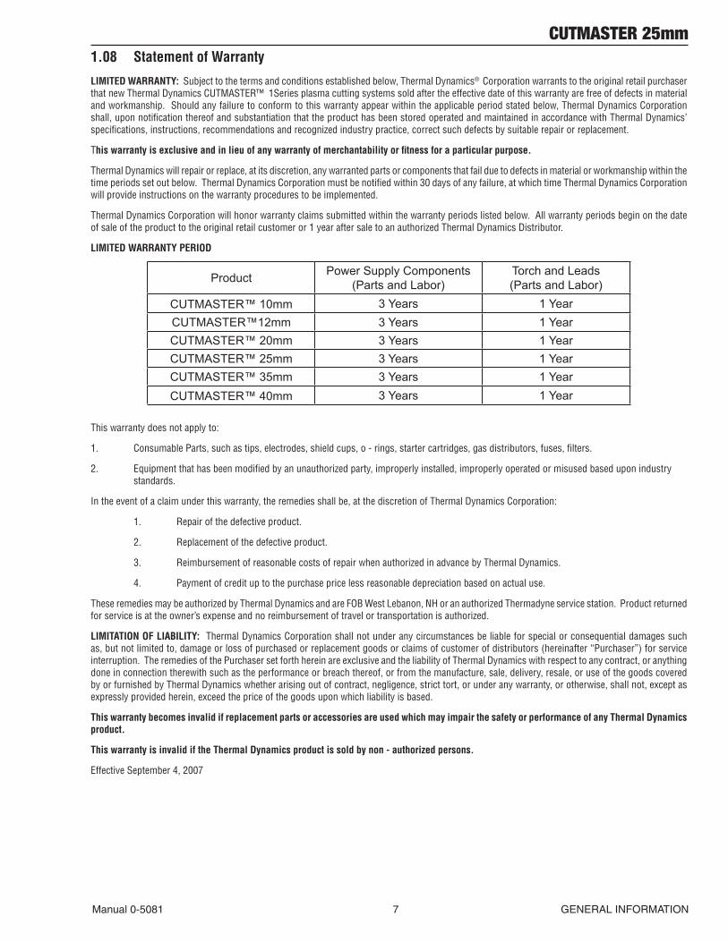
LIMITED WARRANTY PERIOD
Product Power Supply Components (Parts and Labor)
Torch and Leads (Parts and Labor)
CUTMASTER™ 10mm 3 Years 1 YearCUTMASTER™12mm 3 Years 1 YearCUTMASTER™ 20mm 3 Years 1 YearCUTMASTER™ 25mm 3 Years 1 YearCUTMASTER™ 35mm 3 Years 1 YearCUTMASTER™ 40mm 3 Years 1 Year
This warranty does not apply to:
1. Consumable Parts, such as tips, electrodes, shield cups, o - rings, starter cartridges, gas distributors, fuses, filters.
2. Equipment that has been modified by an unauthorized party, improperly installed, improperly operated or misused based upon industry standards.
In the event of a claim under this warranty, the remedies shall be, at the discretion of Thermal Dynamics Corporation:
1. Repair of the defective product.
2. Replacement of the defective product.
3. Reimbursement of reasonable costs of repair when authorized in advance by Thermal Dynamics.
4. Payment of credit up to the purchase price less reasonable depreciation based on actual use.
These remedies may be authorized by Thermal Dynamics and are FOB West Lebanon, NH or an authorized Thermadyne service station. Product returned for service is at the owner’s expense and no reimbursement of travel or transportation is authorized.
LIMITATION OF LIABILITY: Thermal Dynamics Corporation shall not under any circumstances be liable for special or consequential damages such as, but not limited to, damage or loss of purchased or replacement goods or claims of customer of distributors (hereinafter “Purchaser”) for service interruption. The remedies of the Purchaser set forth herein are exclusive and the liability of Thermal Dynamics with respect to any contract, or anything done in connection therewith such as the performance or breach thereof, or from the manufacture, sale, delivery, resale, or use of the goods covered by or furnished by Thermal Dynamics whether arising out of contract, negligence, strict tort, or under any warranty, or otherwise, shall not, except as expressly provided herein, exceed the price of the goods upon which liability is based.
This warranty becomes invalid if replacement parts or accessories are used which may impair the safety or performance of any Thermal Dynamics product.
This warranty is invalid if the Thermal Dynamics product is sold by non - authorized persons.
Effective September 4, 2007

CUTMASTER 25mm
GENERAL INFORMATION 8 Manual 0-5081
This Page Intentionally Blank
CUTMASTER 25mm
Manual 0-5081 2-1 INTRODUCTION
SECTION 2 SYSTEM: INTRODUCTION
2.01 How To Use This ManualThis Service Manual applies to just specification or part numbers listed on page i. To ensure safe operation, read the entire manual, including the chapter on safety instructions and warnings.Throughout this manual, the words WARNING, CAUTION, and NOTE may appear. Pay particular attention to the information provided under these headings. These special annotations are easily recognized as follows:
! WARNING
A WARNING gives information regarding possible personal injury.
CAUTION
A CAUTION refers to possible equipment dam-age.
NOTE
A NOTE offers helpful information concerning certain operating procedures.
Additional copies of this manual may be purchased by contacting Thermadyne at the address and phone number in your area listed in the inside back cover of this manual. Include the Service Manual number and equipment identification numbers.Electronic copies of this manual can also be downloaded at no charge in Acrobat PDF format by going to the Thermal Dynamics web site listed below and clicking on Thermal Dynamics and then on the Literature link:http://www.thermal-dynamics.com
2.02 Equipment IdentificationThe unit’s identification number (specification or part number), model, and serial number usually appear on a data tag attached to the rear panel. Equipment which does not have a data tag such as torch and cable assemblies are identified only by the specification or part number printed on loosely attached card or the shipping container. Record these numbers on the bottom of page 1 for future reference.
2.03 Receipt Of EquipmentWhen you receive the equipment, check it against the invoice to make sure it is complete and in-spect the equipment for possible damage due to shipping. If there is any damage, notify the car-rier immediately to file a claim. Furnish complete information concerning damage claims or ship-ping errors to the location in your area listed in the inside back cover of this manual.Include all equipment identification numbers as described above along with a full description of the parts in error.Move the equipment to the installation site before un-crating the unit. Use care to avoid damaging the equipment when using bars, hammers, etc., to un-crate the unit.
CUTMASTER 25mm
INTRODUCTION 2-2 Manual 0-5081
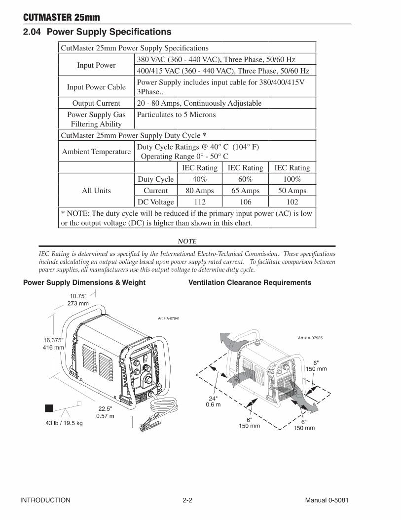
2.04 Power Supply Specifications
CutMaster 25mm Power Supply Specifications
Input Power380 VAC (360 - 440 VAC), Three Phase, 50/60 Hz
400/415 VAC (360 - 440 VAC), Three Phase, 50/60 Hz
Input Power CablePower Supply includes input cable for 380/400/415V 3Phase..
Output Current 20 - 80 Amps, Continuously Adjustable
Power Supply Gas Filtering Ability
Particulates to 5 Microns
CutMaster 25mm Power Supply Duty Cycle *
Ambient TemperatureDuty Cycle Ratings @ 40° C (104° F) Operating Range 0° - 50° C
IEC Rating IEC Rating IEC Rating
All Units
Duty Cycle 40% 60% 100%
Current 80 Amps 65 Amps 50 Amps
DC Voltage 112 106 102
* NOTE: The duty cycle will be reduced if the primary input power (AC) is low or the output voltage (DC) is higher than shown in this chart.
NOTE
IEC Rating is determined as specified by the International Electro-Technical Commission. These specifications include calculating an output voltage based upon power supply rated current. To facilitate comparison between power supplies, all manufacturers use this output voltage to determine duty cycle.
Power Supply Dimensions & Weight Ventilation Clearance Requirements
22.5"0.57 m
43 lb / 19.5 kg
10.75"273 mm
16.375"416 mm
Art # A-07941
6"
150 mm
24"0.6 m
6"150 mm
6"150 mm
Art # A-07925
CUTMASTER 25mm
Manual 0-5081 2-3 INTRODUCTION
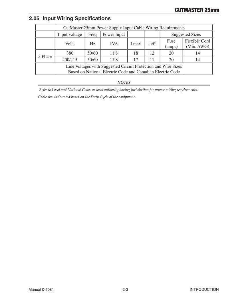
2.05 Input Wiring Specifications
CutMaster 25mm Power Supply Input Cable Wiring Requirements
Input voltage Freq Power Input Suggested Sizes
Volts Hz kVA I max I effFuse
(amps)Flexible Cord (Min. AWG)
3 Phase380 50/60 11.8 18 12 20 14
400/415 50/60 11.8 17 11 20 14
Line Voltages with Suggested Circuit Protection and Wire Sizes Based on National Electric Code and Canadian Electric Code
NOTES
Refer to Local and National Codes or local authority having jurisdiction for proper wiring requirements.
Cable size is de-rated based on the Duty Cycle of the equipment.
CUTMASTER 25mm
INTRODUCTION 2-4 Manual 0-5081
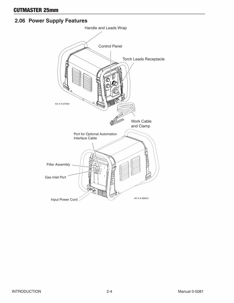
2.06 Power Supply FeaturesHandle and Leads Wrap
Torch Leads Receptacle
Control Panel
Art # A-07942
Work Cableand Clamp
Art # A-08544Input Power Cord
Port for Optional Automation Interface Cable
Gas Inlet Port
Filter Assembly
CUTMASTER 25mm
Manual 0-5081 2T-1 INTRODUCTION
SECTION 2 TORCH: INTRODUCTION
2T.01 Scope of ManualThis manual contains descriptions, operating instructions and maintenance procedures for the 1Torch Models SL60/Manual and SL100/Mecha-nized Plasma Cutting Torches. Service of this equipment is restricted to properly trained person-nel; unqualified personnel are strictly cautioned against attempting repairs or adjustments not covered in this manual, at the risk of voiding the Warranty.Read this manual thoroughly. A complete under-standing of the characteristics and capabilities of this equipment will assure the dependable opera-tion for which it was designed.
2T.02 General DescriptionPlasma torches are similar in design to the auto-motive spark plug. They consist of negative and positive sections separated by a center insulator. Inside the torch, the pilot arc starts in the gap between the negatively charged electrode and the positively charged tip. Once the pilot arc has ionized the plasma gas, the superheated column of gas flows through the small orifice in the torch tip, which is focused on the metal to be cut.A single torch lead provides gas from a single source to be used as both the plasma and second-ary gas. The air flow is divided inside the torch head. Single - gas operation provides a smaller sized torch and inexpensive operation.
NOTE
Refer to Section 2T.05, Introduction To Plasma, for a more detailed description of plasma torch operation.
Refer to the Appendix Pages for additional specifi-cations as related to the Power Supply used.
2T.03 Specifications
A. Torch Configurations
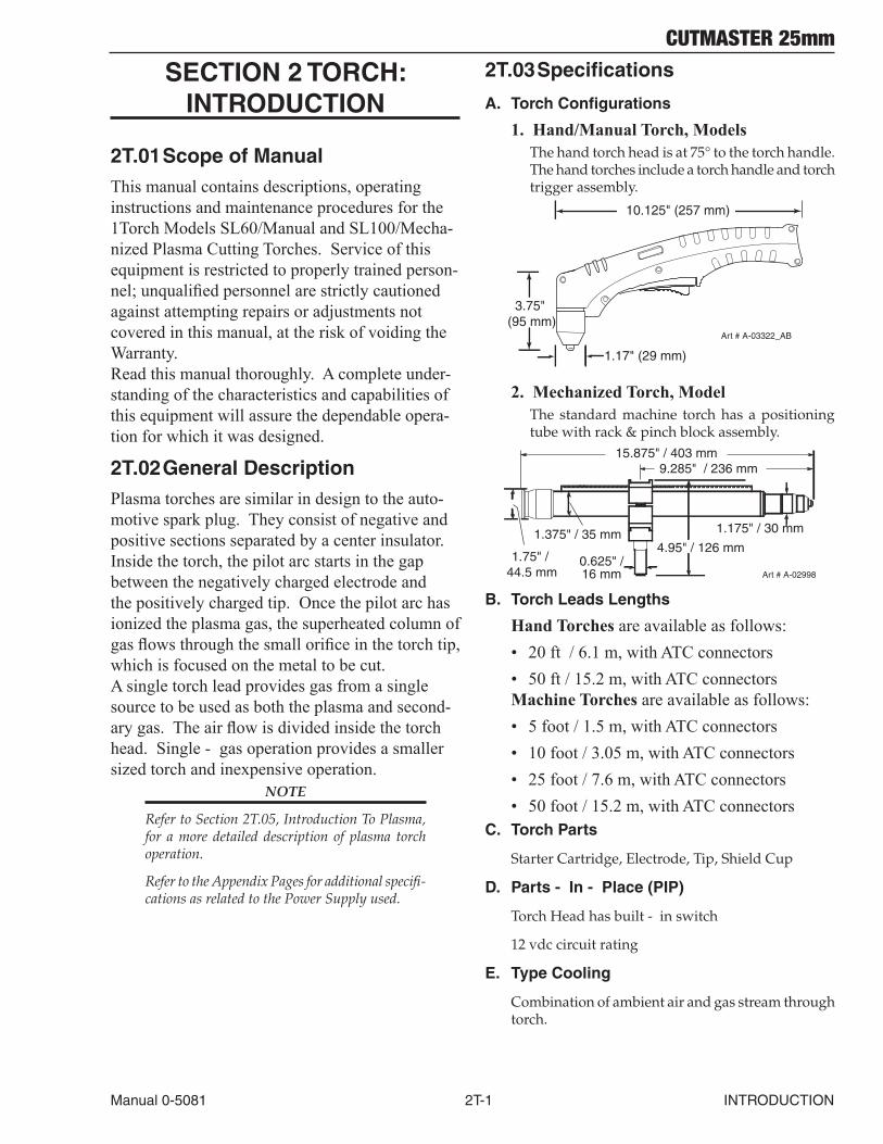
1. Hand/ManualTorch,ModelsThe hand torch head is at 75° to the torch handle. The hand torches include a torch handle and torch trigger assembly.
10.125" (257 mm)
3.75" (95 mm)
1.17" (29 mm)
Art # A-03322_AB
2. MechanizedTorch,ModelThe standard machine torch has a positioning tube with rack & pinch block assembly.
Art # A-02998
1.75" / 44.5 mm
1.375" / 35 mm
15.875" / 403 mm
0.625" /16 mm
4.95" / 126 mm
1.175" / 30 mm
9.285" / 236 mm
B. Torch Leads Lengths
HandTorchesare available as follows:• 20 ft / 6.1 m, with ATC connectors• 50 ft / 15.2 m, with ATC connectors MachineTorchesare available as follows:• 5 foot / 1.5 m, with ATC connectors• 10 foot / 3.05 m, with ATC connectors• 25 foot / 7.6 m, with ATC connectors• 50 foot / 15.2 m, with ATC connectors
C. Torch Parts
Starter Cartridge, Electrode, Tip, Shield Cup
D. Parts - In - Place (PIP)
Torch Head has built - in switch
12 vdc circuit rating
E. Type Cooling
Combination of ambient air and gas stream through torch.
CUTMASTER 25mm
INTRODUCTION 2T-2 Manual 0-5081
F. Torch Ratings
Manual Torch Ratings
Ambient Temperature
104° F 40° C
Duty Cycle 100% @ 60 Amps @ 400 scfh
Maximum Current 80 Amps
Voltage (Vpeak) 500V
Arc Striking Voltage 7kV
Mechanized Torch Ratings
Ambient Temperature
104° F 40° C
Duty Cycle 100% @ 100 Amps @ 400 scfh
Maximum Current 120 Amps
Voltage (Vpeak) 500V
Arc Striking Voltage 7kV
G. Gas Requirements
Manual and Mechanized Torch Gas Specifications
Gas (Plasma and Secondary) Compressed Air
Operating Pressure Refer to NOTE
60 - 95 psi 4.1 - 6.5 bar
Maximum Input Pressure 125 psi / 8.6 bar
Gas Flow (Cutting and Gouging) 300 - 500 scfh 142 - 235 lpm
! WARNING
This torch is not to be used with oxygen (O2).
NOTE
Operating pressure varies with torch model, op-erating amperage, and torch leads length. Refer to gas pressure settings charts for each model.
H. Direct Contact Hazard
For standoff tip the recommended standoff is 3/16 inches / 4.7 mm.
2T.04 Options And AccessoriesFor options and accessories, see section 6.
2T.05 Introduction to Plasma
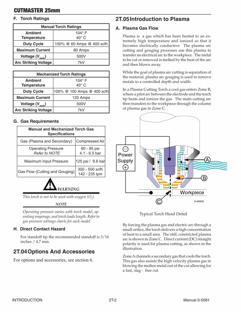
A. Plasma Gas Flow
Plasma is a gas which has been heated to an ex-tremely high temperature and ionized so that it becomes electrically conductive. The plasma arc cutting and gouging processes use this plasma to transfer an electrical arc to the workpiece. The metal to be cut or removed is melted by the heat of the arc and then blown away.
While the goal of plasma arc cutting is separation of the material, plasma arc gouging is used to remove metals to a controlled depth and width.
In a Plasma Cutting Torch a cool gas enters Zone B, where a pilot arc between the electrode and the torch tip heats and ionizes the gas. The main cutting arc then transfers to the workpiece through the column of plasma gas in Zone C.
A-00002
Workpiece
PowerSupply
+
_
C
B
A
Typical Torch Head Detail
By forcing the plasma gas and electric arc through a small orifice, the torch delivers a high concentration of heat to a small area. The stiff, constricted plasma arc is shown in Zone C. Direct current (DC) straight polarity is used for plasma cutting, as shown in the illustration.
Zone A channels a secondary gas that cools the torch. This gas also assists the high velocity plasma gas in blowing the molten metal out of the cut allowing for a fast, slag - free cut.
CUTMASTER 25mm
Manual 0-5081 2T-3 INTRODUCTION
B. Gas Distribution
The single gas used is internally split into plasma and secondary gases.
The plasma gas flows into the torch through the negative lead, through the starter cartridge, around the electrode, and out through the tip orifice.
The secondary gas flows down around the outside of the torch starter cartridge, and out between the tip and shield cup around the plasma arc.
C. Pilot Arc
When the torch is started a pilot arc is established between the electrode and cutting tip. This pilot arc creates a path for the main arc to transfer to the work.
D. Main Cutting Arc
DC power is also used for the main cutting arc. The negative output is connected to the torch electrode through the torch lead. The positive output is con-nected to the workpiece via the work cable and to the torch through a pilot wire.
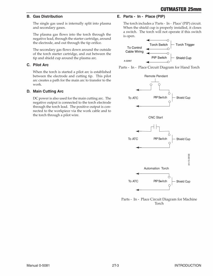
E. Parts - In - Place (PIP)
The torch includes a 'Parts - In - Place' (PIP) circuit. When the shield cup is properly installed, it closes a switch. The torch will not operate if this switch is open.
A-02997
Torch Trigger
PIP Switch Shield Cup
To ControlCable Wiring
Torch Switch
Parts - In - Place Circuit Diagram for Hand Torch
PIP Switch Shield CupTo ATC
CNC Start
PIP Switch Shield Cup
PIP Switch Shield Cup
Remote Pendant
Automation Torch
To ATC
To ATC
Art #
A-0
8168
Parts - In - Place Circuit Diagram for Machine Torch

CUTMASTER 25mm
INTRODUCTION 2T-4 Manual 0-5081
This Page Intentionally Blank
CUTMASTER 25mm
Manual 0-5081 3-1 INSTALLATION
SECTION 3 SYSTEM: INSTALLATION
3.01 Unpacking1. Use the packing lists to identify and account for each item.2. Inspect each item for possible shipping damage. If damage is evident, contact your distributor
and / or shipping company before proceeding with the installation.3. Record Power Supply and Torch model and serial numbers, purchase date and vendor name, in
the information block at the front of this manual.
3.02 Lifting OptionsThe Power Supply includes a handle for handliftingonly. Be sure unit is lifted and transported safely and securely.
! WARNING
Do not touch live electrical parts.
Disconnect input power cord before moving unit.
FALLING EQUIPMENT can cause serious personal injury and can damage equipment.
HANDLE is not for mechanical lifting.
• Only persons of adequate physical strength should lift the unit.• Lift unit by the handles, using two hands. Do not use straps for lifting.• Use optional cart or similar device of adequate capacity to move unit.• Place unit on a proper skid and secure in place before transporting with a fork lift or other vehicle.
CUTMASTER 25mm
INSTALLATION 3-2 Manual 0-5081
3.03 Primary Input Power Connections
CAUTION
Check your power source for correct voltage before plugging in or connecting the unit. The primary power source, fuse, and any extension cords used must conform to local electrical code and the recommended circuit protection and wiring requirements as specified in Section 2.
Connections for Three Phase Input Power
WING
Disconnect input power from the power supply and input cable before attempting this procedure.
These instructions are for installing the input power cable to the power supply and connecting to 380/400/415VAC three phase Primary Input Power.
1. Remove the Power Supply cover per instructions found in section 5.2. Loosen the strain relief on the back panel of the power supply.3. Using a customer supplied four conductor input power cable for rated voltage, strip back the
insulation on the individual wires. 4. Pass the cable being used through the input cable opening / strain relief in the back panel of the
power supply. Refer to Section 2 for power cable specifications.
CAUTION
The primary power source and power cable must conform to local electrical code and the recommended circuit protection and wiring requirements (refer to table in Section 2).
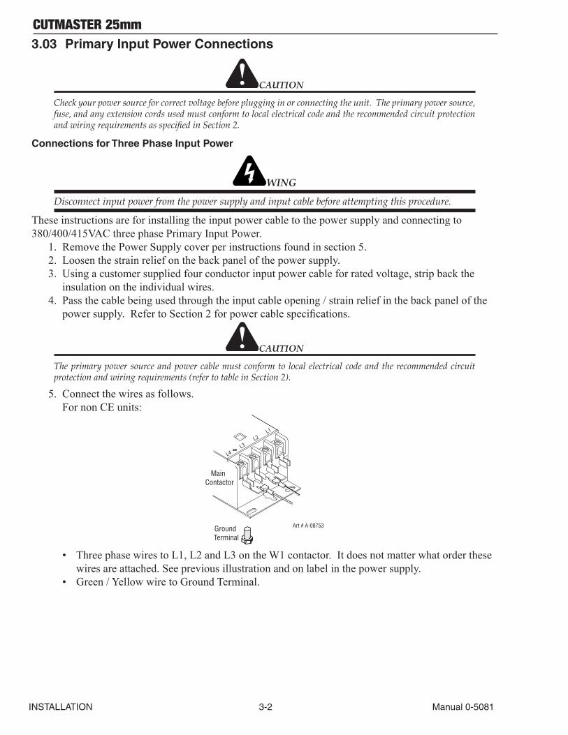
5. Connect the wires as follows.For non CE units:
L4 L3
L2 L1
Art # A-08753Ground Terminal
Main Contactor
• Three phase wires to L1, L2 and L3 on the W1 contactor. It does not matter what order these wires are attached. See previous illustration and on label in the power supply.
• Green / Yellow wire to Ground Terminal.
CUTMASTER 25mm
Manual 0-5081 3-3 INSTALLATION
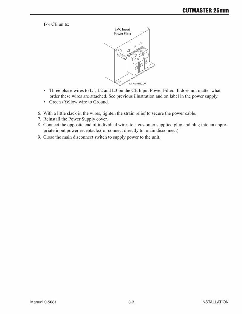
For CE units:
GND
L1L2
L3
EMC Input Power Filter
Art # A-08752_AA
• Three phase wires to L1, L2 and L3 on the CE Input Power Filter. It does not matter what order these wires are attached. See previous illustration and on label in the power supply.
• Green / Yellow wire to Ground.
6. With a little slack in the wires, tighten the strain relief to secure the power cable.7. Reinstall the Power Supply cover.8. Connect the opposite end of individual wires to a customer supplied plug and plug into an appro-
priate input power receptacle.( or connect directly to main disconnect)9. Close the main disconnect switch to supply power to the unit..
CUTMASTER 25mm
INSTALLATION 3-4 Manual 0-5081
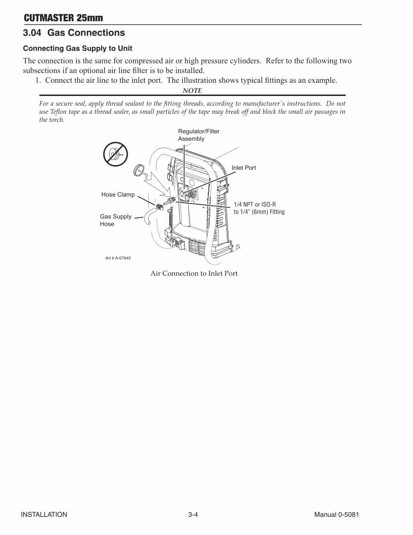
3.04 Gas Connections
Connecting Gas Supply to Unit
The connection is the same for compressed air or high pressure cylinders. Refer to the following two subsections if an optional air line filter is to be installed.
1. Connect the air line to the inlet port. The illustration shows typical fittings as an example. NOTE
For a secure seal, apply thread sealant to the fitting threads, according to manufacturer's instructions. Do not use Teflon tape as a thread sealer, as small particles of the tape may break off and block the small air passages in the torch.
Art # A-07943
Hose Clamp
Regulator/FilterAssembly
Inlet Port
Gas SupplyHose
1/4 NPT or ISO-Rto 1/4” (6mm) Fitting
Air Connection to Inlet Port
CUTMASTER 25mm
Manual 0-5081 3-5 INSTALLATION
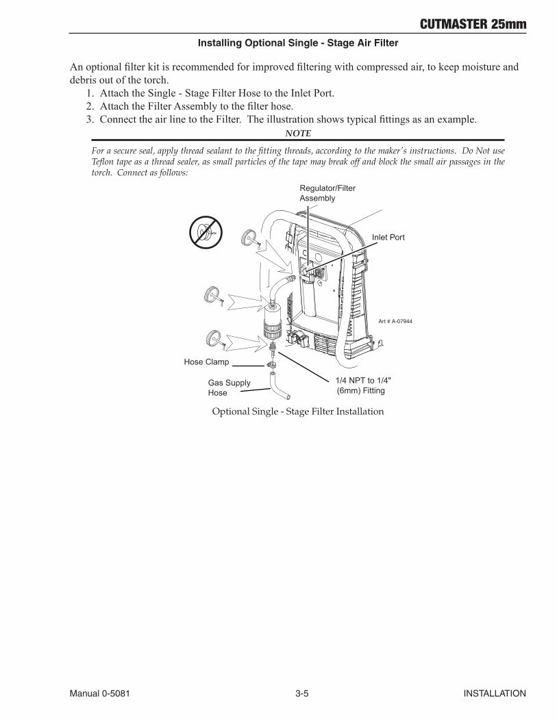
Installing Optional Single - Stage Air Filter
An optional filter kit is recommended for improved filtering with compressed air, to keep moisture and debris out of the torch.
1. Attach the Single - Stage Filter Hose to the Inlet Port.2. Attach the Filter Assembly to the filter hose.3. Connect the air line to the Filter. The illustration shows typical fittings as an example.
NOTE
For a secure seal, apply thread sealant to the fitting threads, according to the maker's instructions. Do Not use Teflon tape as a thread sealer, as small particles of the tape may break off and block the small air passages in the torch. Connect as follows:
Art # A-07944
Hose Clamp
1/4 NPT to 1/4"(6mm) Fitting
Regulator/FilterAssembly
Inlet Port
Gas SupplyHose
Optional Single - Stage Filter Installation
CUTMASTER 25mm
INSTALLATION 3-6 Manual 0-5081
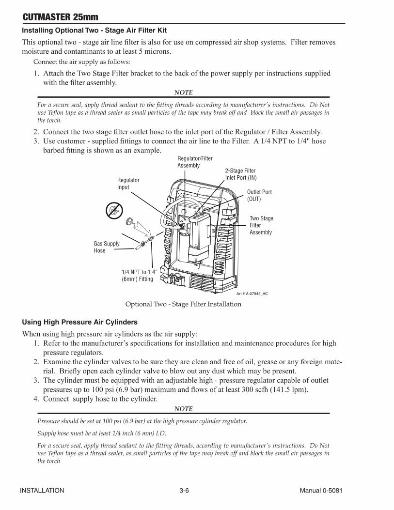
Installing Optional Two - Stage Air Filter Kit
This optional two - stage air line filter is also for use on compressed air shop systems. Filter removes moisture and contaminants to at least 5 microns.
Connect the air supply as follows:
1. Attach the Two Stage Filter bracket to the back of the power supply per instructions supplied with the filter assembly.
NOTE
For a secure seal, apply thread sealant to the fitting threads according to manufacturer's instructions. Do Not use Teflon tape as a thread sealer as small particles of the tape may break off and block the small air passages in the torch.
2. Connect the two stage filter outlet hose to the inlet port of the Regulator / Filter Assembly.3. Use customer - supplied fittings to connect the air line to the Filter. A 1/4 NPT to 1/4" hose
barbed fitting is shown as an example.
Regulator Input
Gas Supply Hose
1/4 NPT to 1/4”(6mm) Fitting
Regulator/FilterAssembly
2-Stage FilterInlet Port (IN)
Outlet Port(OUT)
Two StageFilterAssembly
Art # A-07945_AC
Optional Two - Stage Filter Installation
Using High Pressure Air Cylinders
When using high pressure air cylinders as the air supply:1. Refer to the manufacturer’s specifications for installation and maintenance procedures for high
pressure regulators.2. Examine the cylinder valves to be sure they are clean and free of oil, grease or any foreign mate-
rial. Briefly open each cylinder valve to blow out any dust which may be present.3. The cylinder must be equipped with an adjustable high - pressure regulator capable of outlet
pressures up to 100 psi (6.9 bar) maximum and flows of at least 300 scfh (141.5 lpm).4. Connect supply hose to the cylinder.
NOTE
Pressure should be set at 100 psi (6.9 bar) at the high pressure cylinder regulator.
Supply hose must be at least 1/4 inch (6 mm) I.D.
For a secure seal, apply thread sealant to the fitting threads, according to manufacturer's instructions. Do Not use Teflon tape as a thread sealer, as small particles of the tape may break off and block the small air passages in the torch
CUTMASTER 25mm
Manual 0-5081 3T-1 INSTALLATION
SECTION 3 TORCH: INSTALLATION
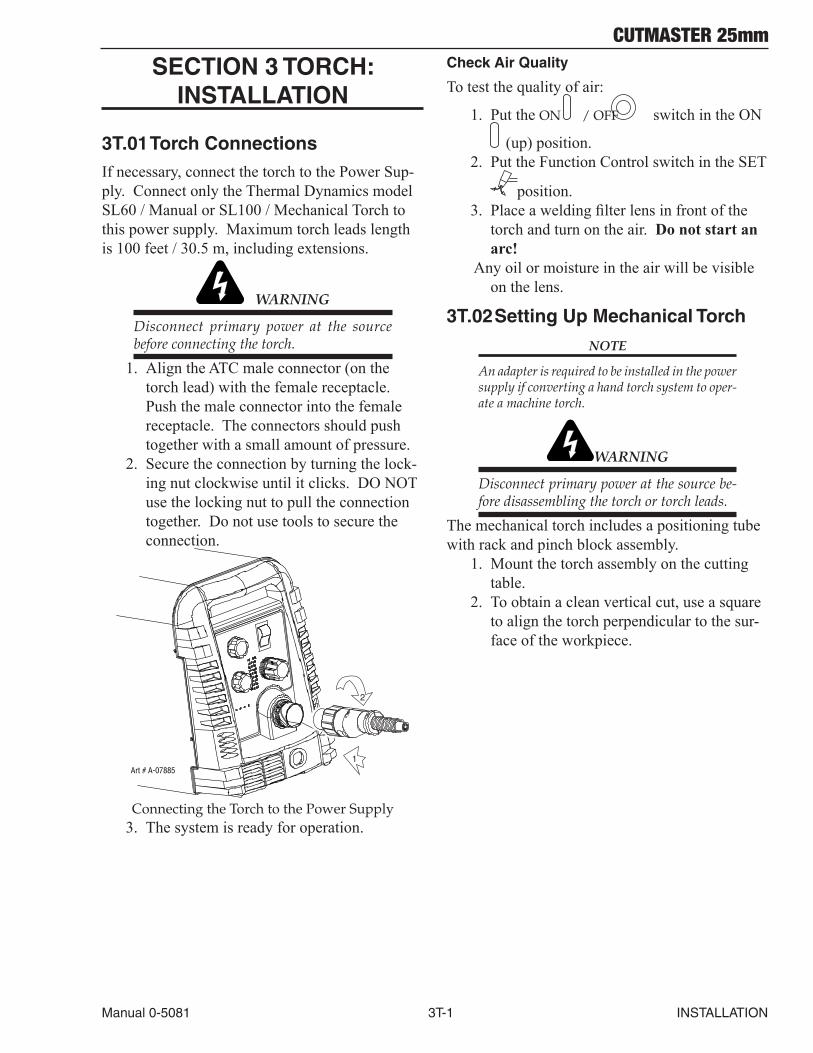
3T.01 Torch ConnectionsIf necessary, connect the torch to the Power Sup-ply. Connect only the Thermal Dynamics model SL60 / Manual or SL100 / Mechanical Torch to this power supply. Maximum torch leads length is 100 feet / 30.5 m, including extensions.
WARNING
Disconnect primary power at the source before connecting the torch.
1. Align the ATC male connector (on the torch lead) with the female receptacle. Push the male connector into the female receptacle. The connectors should push together with a small amount of pressure.
2. Secure the connection by turning the lock-ing nut clockwise until it clicks. DO NOT use the locking nut to pull the connection together. Do not use tools to secure the connection.
1
2
Art # A-07885
Connecting the Torch to the Power Supply3. The system is ready for operation.
Check Air Quality
To test the quality of air:
1. Put the ON / OFF switch in the ON
(up) position. 2. Put the Function Control switch in the SET
position. 3. Place a welding filter lens in front of the
torch and turn on the air. Donotstartanarc!
Any oil or moisture in the air will be visible on the lens.
3T.02 Setting Up Mechanical Torch
NOTE
An adapter is required to be installed in the power supply if converting a hand torch system to oper-ate a machine torch.
WARNING
Disconnect primary power at the source be-fore disassembling the torch or torch leads.
The mechanical torch includes a positioning tube with rack and pinch block assembly.
1. Mount the torch assembly on the cutting table.
2. To obtain a clean vertical cut, use a square to align the torch perpendicular to the sur-face of the workpiece.
CUTMASTER 25mm
INSTALLATION 3T-2 Manual 0-5081
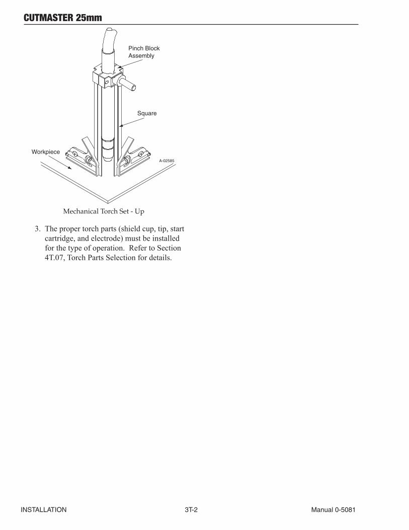
A-02585
Workpiece
Square
Pinch BlockAssembly
Mechanical Torch Set - Up
3. The proper torch parts (shield cup, tip, start cartridge, and electrode) must be installed for the type of operation. Refer to Section 4T.07, Torch Parts Selection for details.
CUTMASTER 25mm
Manual 0-5081 4-1 OPERATION
SECTION 4 SYSTEM: OPERATION
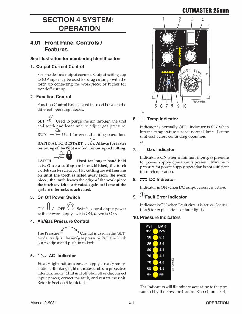
4.01 Front Panel Controls / Features
See Illustration for numbering Identification
1. Output Current Control
Sets the desired output current. Output settings up to 60 Amps may be used for drag cutting (with the torch tip contacting the workpiece) or higher for standoff cutting.
2. Function Control
Function Control Knob, Used to select between the different operating modes.
SET Used to purge the air through the unit and torch and leads and to adjust gas pressure.
RUN Used for general cutting operations
RAPID AUTO RESTART Allows for faster restarting of the Pilot Arc for uninterrupted cutting.
LATCH Used for longer hand held cuts. Once a cutting arc is established, the torch switch can be released. The cutting arc will remain on until the torch is lifted away from the work piece, the torch leaves the edge of the work piece the torch switch is activated again or if one of the system interlocks is activated.
3. On Off Power Switch
ON / OFF Switch controls input power to the power supply. Up is ON, down is OFF.
4. Air/Gas Pressure Control
The Pressure + Control is used in the "SET" mode to adjust the air/gas pressure. Pull the knob out to adjust and push in to lock.
5. AC Indicator
Steady light indicates power supply is ready for op-eration. Blinking light indicates unit is in protective interlock mode. Shut unit off, shut off or disconnect input power, correct the fault, and restart the unit. Refer to Section 5 for details.
A+
PSI BARMAX MAX
MIN MIN
!
1 2 3 4
5 6 7 8 9Art# A-07886
MIN MAX
10
6. Temp Indicator
Indicator is normally OFF. Indicator is ON when internal temperature exceeds normal limits. Let the unit cool before continuing operation.
7. Gas Indicator
Indicator is ON when minimum input gas pressure for power supply operation is present. Minimum pressure for power supply operation is not sufficient for torch operation.
8. DC Indicator
Indicator is ON when DC output circuit is active.
9. ! Fault Error Indicator
Indicator is ON when Fault circuit is active. See sec-tion 5 for explanations of fault lights.
10. Pressure Indicators
PSI BARMAX MAX
MIN MIN
8075
70
65
5.585 5.9
90 6.3
5.2
4.8
4.5 Art #
A-0
8170
The Indicators will illuminate according to the pres-sure set by the Pressure Control Knob (number 4).
CUTMASTER 25mm
OPERATION 4-2 Manual 0-5081
4.02 Preparations for OperationAt the start of each operating session:
WARNING
Disconnect primary power at the source before assembling or disassembling power supply, torch parts, or torch and leads as-semblies.
Torch Parts Selection
Check the torch for proper assembly and appropri-ate torch parts. The torch parts must correspond with the type of operation, and with the amperage output of this Power Supply (80 amps maximum). Refer to Section 4T.07 and following for torch parts selection.
Torch Connection
Check that the torch is properly connected. Only Thermal Dynamics model SL60 / Manual or SL100 / Mechanical Torches may be connected to this Power Supply. See Section 3T of this manual.
Check Primary Input Power Source
1. Check the power source for proper input voltage. Make sure the input power source meets the power requirements for the unit per Section 2, Specifications.
2. Connect the input power cable (or close the main disconnect switch) to supply power to the system.
Air Source
Ensure source meets requirements (refer to Section 2). Check connections and turn air supply on.
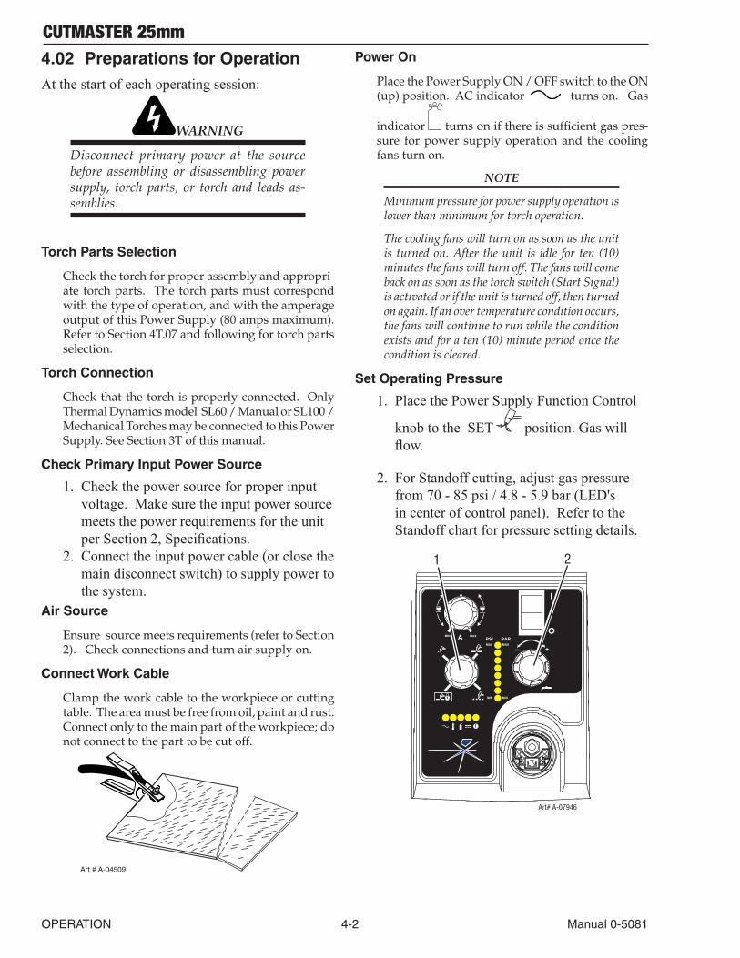
Connect Work Cable
Clamp the work cable to the workpiece or cutting table. The area must be free from oil, paint and rust. Connect only to the main part of the workpiece; do not connect to the part to be cut off.
Art # A-04509
Power On
Place the Power Supply ON / OFF switch to the ON (up) position. AC indicator turns on. Gas
indicator turns on if there is sufficient gas pres-sure for power supply operation and the cooling fans turn on.
NOTE
Minimum pressure for power supply operation is lower than minimum for torch operation.
The cooling fans will turn on as soon as the unit is turned on. After the unit is idle for ten (10) minutes the fans will turn off. The fans will come back on as soon as the torch switch (Start Signal) is activated or if the unit is turned off, then turned on again. If an over temperature condition occurs, the fans will continue to run while the condition exists and for a ten (10) minute period once the condition is cleared.
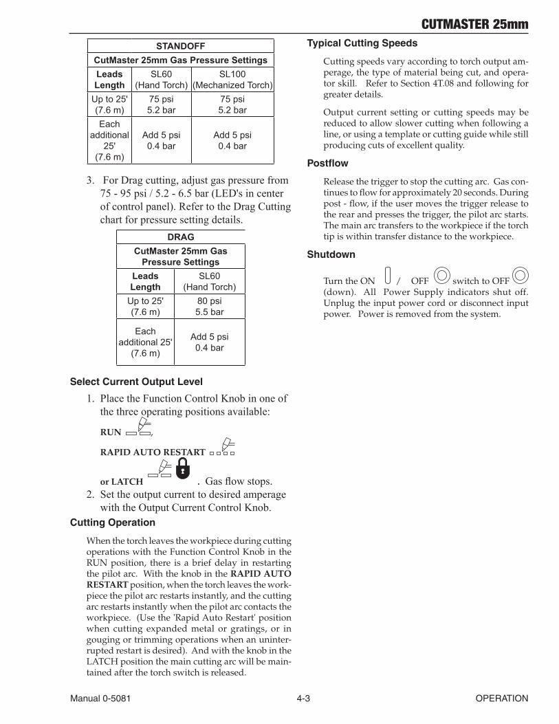
Set Operating Pressure
1. Place the Power Supply Function Control
knob to the SET position. Gas will flow.
2. For Standoff cutting, adjust gas pressure from 70 - 85 psi / 4.8 - 5.9 bar (LED's in center of control panel). Refer to the Standoff chart for pressure setting details.
A+
PSI BARMAX MAX
MIN MIN
!
1 2
Art# A-07946
MIN MAX
CUTMASTER 25mm
Manual 0-5081 4-3 OPERATION
STANDOFFCutMaster 25mm Gas Pressure SettingsLeads Length
SL60 (Hand Torch)
SL100 (Mechanized Torch)
Up to 25' (7.6 m)
75 psi 5.2 bar
75 psi 5.2 bar
Each additional
25' (7.6 m)
Add 5 psi 0.4 bar
Add 5 psi 0.4 bar
3. For Drag cutting, adjust gas pressure from 75 - 95 psi / 5.2 - 6.5 bar (LED's in center of control panel). Refer to the Drag Cutting chart for pressure setting details.
DRAGCutMaster 25mm Gas
Pressure SettingsLeads Length
SL60 (Hand Torch)
Up to 25' (7.6 m)
80 psi 5.5 bar
Each additional 25'
(7.6 m)
Add 5 psi 0.4 bar
Select Current Output Level
1. Place the Function Control Knob in one of the three operating positions available:
RUN ,
RAPID AUTO RESTART
or LATCH . Gas flow stops. 2. Set the output current to desired amperage
with the Output Current Control Knob.Cutting Operation
When the torch leaves the workpiece during cutting operations with the Function Control Knob in the RUN position, there is a brief delay in restarting the pilot arc. With the knob in the RAPID AUTO RESTART position, when the torch leaves the work-piece the pilot arc restarts instantly, and the cutting arc restarts instantly when the pilot arc contacts the workpiece. (Use the 'Rapid Auto Restart' position when cutting expanded metal or gratings, or in gouging or trimming operations when an uninter-rupted restart is desired). And with the knob in the LATCH position the main cutting arc will be main-tained after the torch switch is released.
Typical Cutting Speeds
Cutting speeds vary according to torch output am-perage, the type of material being cut, and opera-tor skill. Refer to Section 4T.08 and following for greater details.
Output current setting or cutting speeds may be reduced to allow slower cutting when following a line, or using a template or cutting guide while still producing cuts of excellent quality.
Postflow
Release the trigger to stop the cutting arc. Gas con-tinues to flow for approximately 20 seconds. During post - flow, if the user moves the trigger release to the rear and presses the trigger, the pilot arc starts. The main arc transfers to the workpiece if the torch tip is within transfer distance to the workpiece.
Shutdown
Turn the ON / OFF switch to OFF (down). All Power Supply indicators shut off. Unplug the input power cord or disconnect input power. Power is removed from the system.

CUTMASTER 25mm
OPERATION 4-4 Manual 0-5081
This Page Intentionally Blank
CUTMASTER 25mm
Manual 0-5081 4T-1 OPERATION
SECTION 4 TORCH: OPERATION
4T.01 Torch Parts SelectionDepending on the type of operation to be done determines the torch parts to be used.
Typeofoperation:Drag cutting, standoff cutting or gouging
Torchparts:Shield Cup, Cutting Tip, Electrode and Starter Cartridge
NOTE
Refer to Section 4T.07 and following for additional information on torch parts.
Change the torch parts for a different operation as follows:
WARNING
Disconnect primary power at the source be-fore assembling or disassembling torch parts, or torch and leads assemblies.
NOTE
The shield cup holds the tip and starter cartridge in place. Position the torch with the shield cup facing upward to keep these parts from falling out when the cup is removed.
1. Unscrew and remove the shield cup assem-bly from the torch head.
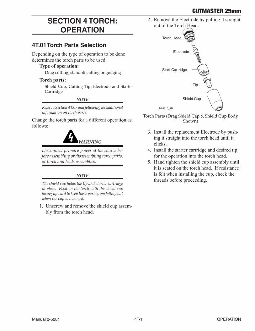
2. Remove the Electrode by pulling it straight out of the Torch Head.
A-03510_AB
Electrode
Start Cartridge
Tip
Shield Cup
Torch Head
Torch Parts (Drag Shield Cap & Shield Cup Body Shown)
3. Install the replacement Electrode by push-ing it straight into the torch head until it clicks.
4. Install the starter cartridge and desired tip for the operation into the torch head.
5. Hand tighten the shield cup assembly until it is seated on the torch head. If resistance is felt when installing the cup, check the threads before proceeding.
CUTMASTER 25mm
OPERATION 4T-2 Manual 0-5081
4T.02 Cut Quality
NOTES
Cut quality depends heavily on setup and parameters such as torch standoff, alignment with the workpiece, cutting speed, gas pressures, and operator ability.
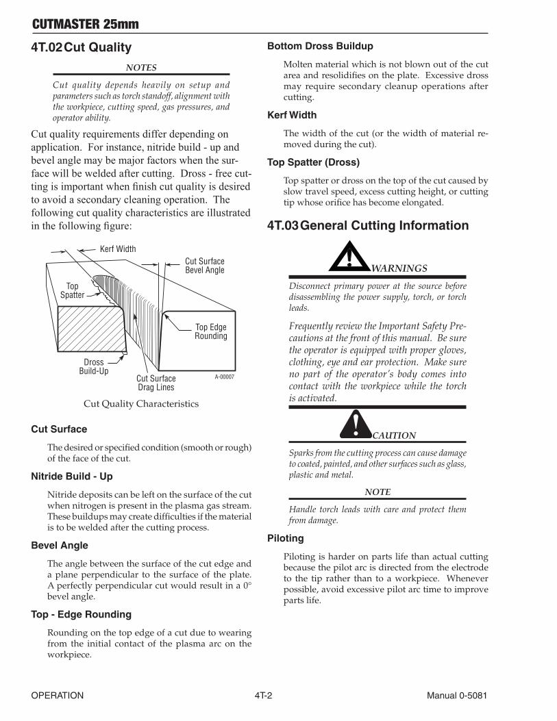
Cut quality requirements differ depending on application. For instance, nitride build - up and bevel angle may be major factors when the sur-face will be welded after cutting. Dross - free cut-ting is important when finish cut quality is desired to avoid a secondary cleaning operation. The following cut quality characteristics are illustrated in the following figure:
Kerf WidthCut SurfaceBevel Angle
Top EdgeRounding
Cut SurfaceDrag Lines
DrossBuild-Up
TopSpatter
A-00007
Cut Quality Characteristics
Cut Surface
The desired or specified condition (smooth or rough) of the face of the cut.
Nitride Build - Up
Nitride deposits can be left on the surface of the cut when nitrogen is present in the plasma gas stream. These buildups may create difficulties if the material is to be welded after the cutting process.
Bevel Angle
The angle between the surface of the cut edge and a plane perpendicular to the surface of the plate. A perfectly perpendicular cut would result in a 0° bevel angle.
Top - Edge Rounding
Rounding on the top edge of a cut due to wearing from the initial contact of the plasma arc on the workpiece.
Bottom Dross Buildup
Molten material which is not blown out of the cut area and resolidifies on the plate. Excessive dross may require secondary cleanup operations after cutting.
Kerf Width
The width of the cut (or the width of material re-moved during the cut).
Top Spatter (Dross)
Top spatter or dross on the top of the cut caused by slow travel speed, excess cutting height, or cutting tip whose orifice has become elongated.
4T.03 General Cutting Information
! WARNINGS
Disconnect primary power at the source before disassembling the power supply, torch, or torch leads.
Frequently review the Important Safety Pre-cautions at the front of this manual. Be sure the operator is equipped with proper gloves, clothing, eye and ear protection. Make sure no part of the operator’s body comes into contact with the workpiece while the torch is activated.
CAUTION
Sparks from the cutting process can cause damage to coated, painted, and other surfaces such as glass, plastic and metal.
NOTE
Handle torch leads with care and protect them from damage.
Piloting
Piloting is harder on parts life than actual cutting because the pilot arc is directed from the electrode to the tip rather than to a workpiece. Whenever possible, avoid excessive pilot arc time to improve parts life.
CUTMASTER 25mm
Manual 0-5081 4T-3 OPERATION
Torch Standoff
Improper standoff (the distance between the torch tip and workpiece) can adversely affect tip life as well as shield cup life. Standoff may also signifi-cantly affect the bevel angle. Reducing standoff will generally result in a more square cut.
Edge Starting
For edge starts, hold the torch perpendicular to the workpiece with the front of the tip near (not touch-ing) the edge of the workpiece at the point where the cut is to start. When starting at the edge of the plate, do not pause at the edge and force the arc to "reach" for the edge of the metal. Establish the cut-ting arc as quickly as possible.
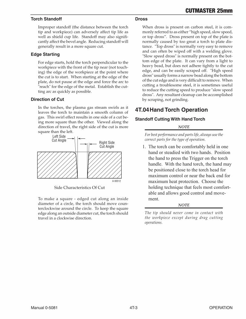
Direction of Cut
In the torches, the plasma gas stream swirls as it leaves the torch to maintain a smooth column of gas. This swirl effect results in one side of a cut be-ing more square than the other. Viewed along the direction of travel, the right side of the cut is more square than the left.
Right SideCut Angle
Left SideCut Angle
A-00512
Side Characteristics Of Cut
To make a square - edged cut along an inside diameter of a circle, the torch should move coun-terclockwise around the circle. To keep the square edge along an outside diameter cut, the torch should travel in a clockwise direction.
Dross
When dross is present on carbon steel, it is com-monly referred to as either “high speed, slow speed, or top dross”. Dross present on top of the plate is normally caused by too great a torch to plate dis-tance. "Top dross" is normally very easy to remove and can often be wiped off with a welding glove. "Slow speed dross" is normally present on the bot-tom edge of the plate. It can vary from a light to heavy bead, but does not adhere tightly to the cut edge, and can be easily scraped off. "High speed dross" usually forms a narrow bead along the bottom of the cut edge and is very difficult to remove. When cutting a troublesome steel, it is sometimes useful to reduce the cutting speed to produce "slow speed dross". Any resultant cleanup can be accomplished by scraping, not grinding.
4T.04 Hand Torch Operation
Standoff Cutting With Hand Torch
NOTE
For best performance and parts life, always use the correct parts for the type of operation.
1. The torch can be comfortably held in one hand or steadied with two hands. Position the hand to press the Trigger on the torch handle. With the hand torch, the hand may be positioned close to the torch head for maximum control or near the back end for maximum heat protection. Choose the holding technique that feels most comfort-able and allows good control and move-ment.
NOTE
The tip should never come in contact with the workpiece except during drag cutting operations.
CUTMASTER 25mm
OPERATION 4T-4 Manual 0-5081
2. Depending on the cutting operation, do one of the following:a. For edgestarts, hold the torch perpen-
dicular to the workpiece with the front of the tip on the edge of the workpiece at the point where the cut is to start.
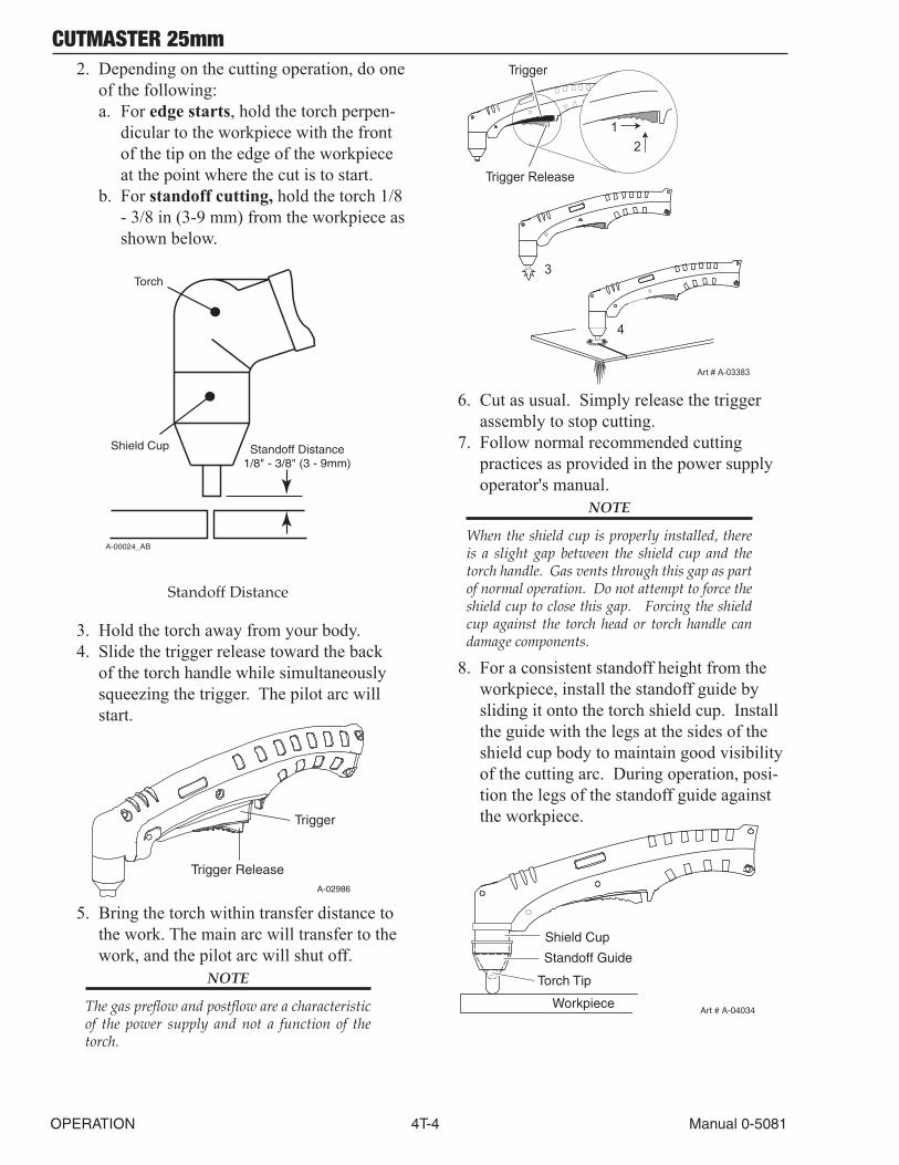
b. For standoffcutting, hold the torch 1/8 - 3/8 in (3-9 mm) from the workpiece as shown below.
A-00024_AB
Shield Cup
Torch
Standoff Distance1/8" - 3/8" (3 - 9mm)
Standoff Distance
3. Hold the torch away from your body.4. Slide the trigger release toward the back
of the torch handle while simultaneously squeezing the trigger. The pilot arc will start.
A-02986
Trigger
Trigger Release
5. Bring the torch within transfer distance to
the work. The main arc will transfer to the work, and the pilot arc will shut off.
NOTE
The gas preflow and postflow are a characteristic of the power supply and not a function of the torch.
3
4
Art # A-03383
Trigger
21
Trigger Release
6. Cut as usual. Simply release the trigger assembly to stop cutting.
7. Follow normal recommended cutting practices as provided in the power supply operator's manual.
NOTE
When the shield cup is properly installed, there is a slight gap between the shield cup and the torch handle. Gas vents through this gap as part of normal operation. Do not attempt to force the shield cup to close this gap. Forcing the shield cup against the torch head or torch handle can damage components.
8. For a consistent standoff height from the workpiece, install the standoff guide by sliding it onto the torch shield cup. Install the guide with the legs at the sides of the shield cup body to maintain good visibility of the cutting arc. During operation, posi-tion the legs of the standoff guide against the workpiece.
Shield Cup
Workpiece
Standoff Guide
Art # A-04034
Torch Tip
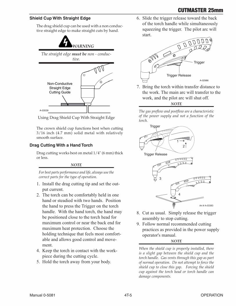
CUTMASTER 25mm
Manual 0-5081 4T-5 OPERATION
Shield Cup With Straight Edge
The drag shield cup can be used with a non conduc-tive straight edge to make straight cuts by hand.
WARNING
The straight edge must be non - conduc-tive.
A-03539
Non-ConductiveStraight EdgeCutting Guide
Using Drag Shield Cup With Straight Edge
The crown shield cup functions best when cutting 3/16 inch (4.7 mm) solid metal with relatively smooth surface.
Drag Cutting With a Hand Torch
Drag cutting works best on metal 1/4" (6 mm) thick or less.
NOTE
For best parts performance and life, always use the correct parts for the type of operation.
1. Install the drag cutting tip and set the out-put current.
2. The torch can be comfortably held in one hand or steadied with two hands. Position the hand to press the Trigger on the torch handle. With the hand torch, the hand may be positioned close to the torch head for maximum control or near the back end for maximum heat protection. Choose the holding technique that feels most comfort-able and allows good control and move-ment.
4. Keep the torch in contact with the work-piece during the cutting cycle.
5. Hold the torch away from your body.
6. Slide the trigger release toward the back of the torch handle while simultaneously squeezing the trigger. The pilot arc will start.
A-02986
Trigger
Trigger Release
7. Bring the torch within transfer distance to
the work. The main arc will transfer to the work, and the pilot arc will shut off.
NOTE
The gas preflow and postflow are a characteristic of the power supply and not a function of the torch.
3
4
Art # A-03383
Trigger
21
Trigger Release
8. Cut as usual. Simply release the trigger assembly to stop cutting.
9. Follow normal recommended cutting practices as provided in the power supply operator's manual.
NOTE
When the shield cup is properly installed, there is a slight gap between the shield cup and the torch handle. Gas vents through this gap as part of normal operation. Do not attempt to force the shield cup to close this gap. Forcing the shield cup against the torch head or torch handle can damage components.
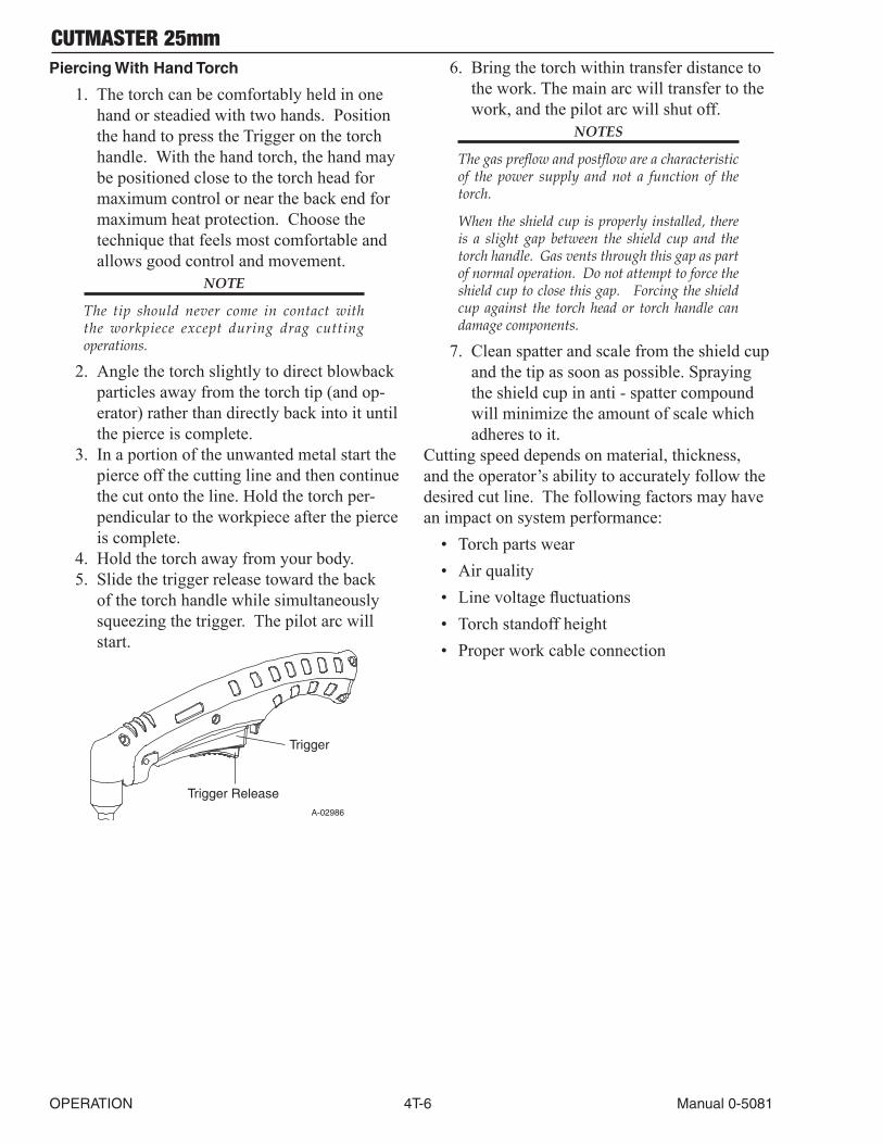
CUTMASTER 25mm
OPERATION 4T-6 Manual 0-5081
Piercing With Hand Torch
1. The torch can be comfortably held in one hand or steadied with two hands. Position the hand to press the Trigger on the torch handle. With the hand torch, the hand may be positioned close to the torch head for maximum control or near the back end for maximum heat protection. Choose the technique that feels most comfortable and allows good control and movement.
NOTE
The tip should never come in contact with the workpiece except during drag cutting operations.
2. Angle the torch slightly to direct blowback particles away from the torch tip (and op-erator) rather than directly back into it until the pierce is complete.
3. In a portion of the unwanted metal start the pierce off the cutting line and then continue the cut onto the line. Hold the torch per-pendicular to the workpiece after the pierce is complete.
4. Hold the torch away from your body.5. Slide the trigger release toward the back
of the torch handle while simultaneously squeezing the trigger. The pilot arc will start.
A-02986
Trigger
Trigger Release
6. Bring the torch within transfer distance to the work. The main arc will transfer to the work, and the pilot arc will shut off.
NOTES
The gas preflow and postflow are a characteristic of the power supply and not a function of the torch.
When the shield cup is properly installed, there is a slight gap between the shield cup and the torch handle. Gas vents through this gap as part of normal operation. Do not attempt to force the shield cup to close this gap. Forcing the shield cup against the torch head or torch handle can damage components.
7. Clean spatter and scale from the shield cup and the tip as soon as possible. Spraying the shield cup in anti - spatter compound will minimize the amount of scale which adheres to it.
Cutting speed depends on material, thickness, and the operator’s ability to accurately follow the desired cut line. The following factors may have an impact on system performance:
• Torch parts wear• Air quality• Line voltage fluctuations• Torch standoff height• Proper work cable connection
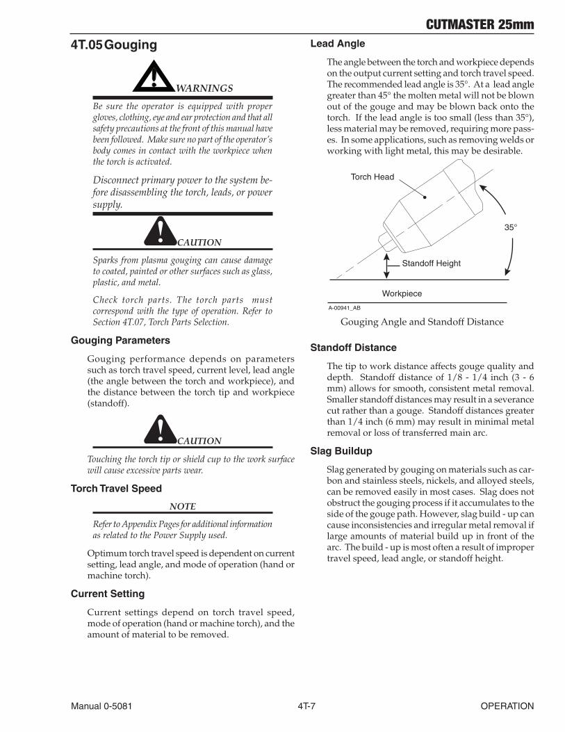
CUTMASTER 25mm
Manual 0-5081 4T-7 OPERATION
4T.05 Gouging
! WARNINGS
Be sure the operator is equipped with proper gloves, clothing, eye and ear protection and that all safety precautions at the front of this manual have been followed. Make sure no part of the operator’s body comes in contact with the workpiece when the torch is activated.
Disconnect primary power to the system be-fore disassembling the torch, leads, or power supply.
CAUTION
Sparks from plasma gouging can cause damage to coated, painted or other surfaces such as glass, plastic, and metal.
Check torch parts. The torch parts must correspond with the type of operation. Refer to Section 4T.07, Torch Parts Selection.
Gouging Parameters
Gouging performance depends on parameters such as torch travel speed, current level, lead angle (the angle between the torch and workpiece), and the distance between the torch tip and workpiece (standoff).
CAUTION
Touching the torch tip or shield cup to the work surface will cause excessive parts wear.
Torch Travel Speed
NOTE
Refer to Appendix Pages for additional information as related to the Power Supply used.
Optimum torch travel speed is dependent on current setting, lead angle, and mode of operation (hand or machine torch).
Current Setting
Current settings depend on torch travel speed, mode of operation (hand or machine torch), and the amount of material to be removed.
Lead Angle
The angle between the torch and workpiece depends on the output current setting and torch travel speed. The recommended lead angle is 35°. At a lead angle greater than 45° the molten metal will not be blown out of the gouge and may be blown back onto the torch. If the lead angle is too small (less than 35°), less material may be removed, requiring more pass-es. In some applications, such as removing welds or working with light metal, this may be desirable.
35°
Workpiece
Torch Head
Standoff Height
A-00941_AB
Gouging Angle and Standoff Distance
Standoff Distance
The tip to work distance affects gouge quality and depth. Standoff distance of 1/8 - 1/4 inch (3 - 6 mm) allows for smooth, consistent metal removal. Smaller standoff distances may result in a severance cut rather than a gouge. Standoff distances greater than 1/4 inch (6 mm) may result in minimal metal removal or loss of transferred main arc.
Slag Buildup
Slag generated by gouging on materials such as car-bon and stainless steels, nickels, and alloyed steels, can be removed easily in most cases. Slag does not obstruct the gouging process if it accumulates to the side of the gouge path. However, slag build - up can cause inconsistencies and irregular metal removal if large amounts of material build up in front of the arc. The build - up is most often a result of improper travel speed, lead angle, or standoff height.
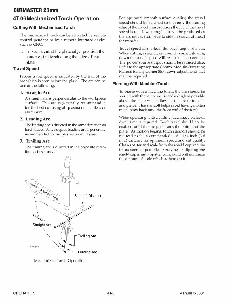
CUTMASTER 25mm
OPERATION 4T-8 Manual 0-5081
4T.06 Mechanized Torch Operation
Cutting With Mechanized Torch
The mechanized torch can be activated by remote control pendant or by a remote interface device such as CNC.
1. To start a cut at the plate edge, position the center of the torch along the edge of the plate.
Travel Speed
Proper travel speed is indicated by the trail of the arc which is seen below the plate. The arc can be one of the following:
1. StraightArcA straight arc is perpendicular to the workpiece surface. This arc is generally recommended for the best cut using air plasma on stainless or aluminum.
2. LeadingArcThe leading arc is directed in the same direction as torch travel. A five degree leading arc is generally recommended for air plasma on mild steel.
3. TrailingArcThe trailing arc is directed in the opposite direc-tion as torch travel.
Standoff Distance
Straight Arc
Trailing Arc
Leading Arc
Direction of Torch Travel
A-02586
Mechanized Torch Operation
For optimum smooth surface quality, the travel speed should be adjusted so that only the leading edge of the arc column produces the cut. If the travel speed is too slow, a rough cut will be produced as the arc moves from side to side in search of metal for transfer.
Travel speed also affects the bevel angle of a cut. When cutting in a circle or around a corner, slowing down the travel speed will result in a squarer cut. The power source output should be reduced also. Refer to the appropriate Control Module Operating Manual for any Corner Slowdown adjustments that may be required.
Piercing With Machine Torch
To pierce with a machine torch, the arc should be started with the torch positioned as high as possible above the plate while allowing the arc to transfer and pierce. This standoff helps avoid having molten metal blow back onto the front end of the torch.
When operating with a cutting machine, a pierce or dwell time is required. Torch travel should not be enabled until the arc penetrates the bottom of the plate. As motion begins, torch standoff should be reduced to the recommended 1/8 - 1/4 inch (3-6 mm) distance for optimum speed and cut quality. Clean spatter and scale from the shield cup and the tip as soon as possible. Spraying or dipping the shield cup in anti - spatter compound will minimize the amount of scale which adheres to it.
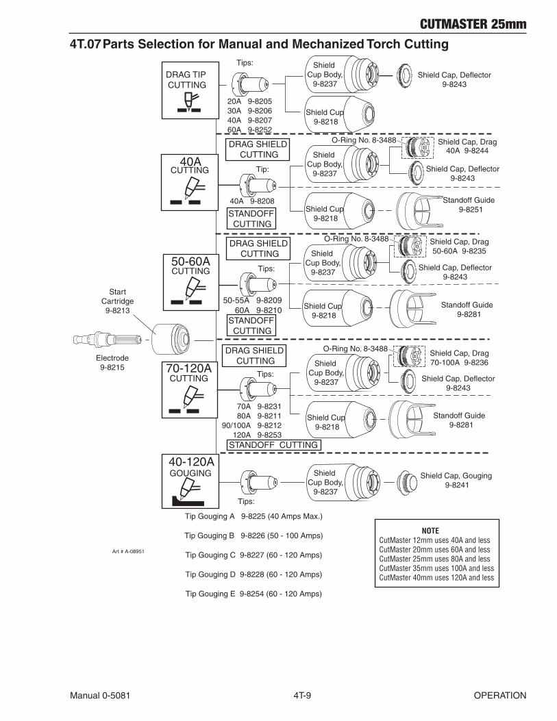
CUTMASTER 25mm
Manual 0-5081 4T-9 OPERATION
4T.07 Parts Selection for Manual and Mechanized Torch Cutting
StartCartridge9-8213
Electrode9-8215
Tips:
20A 9-820530A 9-820640A 9-820760A 9-8252
Tip Gouging A 9-8225 (40 Amps Max.)
Tip Gouging B 9-8226 (50 - 100 Amps)
Tip Gouging C 9-8227 (60 - 120 Amps)
Tip Gouging D 9-8228 (60 - 120 Amps)
Tip Gouging E 9-8254 (60 - 120 Amps)
Shield Cap, Gouging 9-8241
Shield Cap, Drag40A 9-8244
40A 9-8208
50-55A 9-8209 60A 9-8210
70A 9-8231 80A 9-821190/100A 9-8212
120A 9-8253
Shield Cap, Drag50-60A 9-8235
Shield Cap, Drag70-100A 9-8236
Shield Cup Body,
9-8237
70-120A
50-60A
40A
Shield Cap, Deflector9-8243
Shield Cup Body,
9-8237
Shield Cup 9-8218
Tip:
Tips:
Tips:
Tips:
DRAG TIP CUTTING
40-120AGOUGING
CUTTING
CUTTING
CUTTING
Art # A-08951
DRAG SHIELD CUTTING
Shield Cap, Deflector9-8243
Shield Cup Body,
9-8237
Shield Cup 9-8218
O-Ring No. 8-3488
Standoff Guide 9-8281
Shield Cap, Deflector9-8243
Shield Cup Body,
9-8237
Shield Cup 9-8218
O-Ring No. 8-3488
STANDOFF CUTTING
DRAG SHIELD CUTTING
Standoff Guide 9-8281
STANDOFF CUTTING
DRAG SHIELD CUTTING
STANDOFF CUTTING
Shield Cap, Deflector9-8243
Shield Cup Body,
9-8237
Shield Cup 9-8218
O-Ring No. 8-3488
Standoff Guide 9-8251
NOTECutMaster 12mm uses 40A and lessCutMaster 20mm uses 60A and lessCutMaster 25mm uses 80A and lessCutMaster 35mm uses 100A and lessCutMaster 40mm uses 120A and less
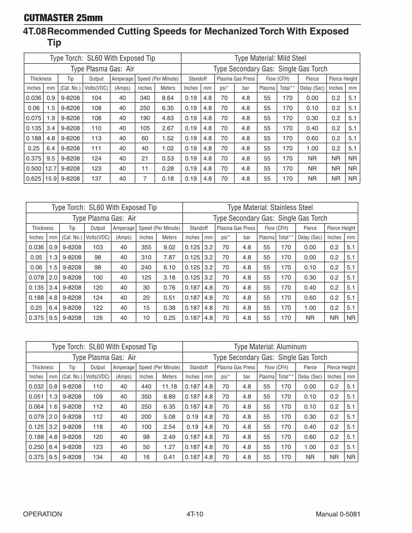
CUTMASTER 25mm
OPERATION 4T-10 Manual 0-5081
4T.08 Recommended Cutting Speeds for Mechanized Torch With Exposed Tip
Type Torch: SL60 With Exposed Tip Type Material: Mild SteelType Plasma Gas: Air Type Secondary Gas: Single Gas Torch
Thickness Tip Output Amperage Speed (Per Minute) Standoff Plasma Gas Press Flow (CFH) Pierce Pierce Height
Inches mm (Cat. No.) Volts(VDC) (Amps) Inches Meters Inches mm psi* bar Plasma Total** Delay (Sec) Inches mm
0.036 0.9 9-8208 104 40 340 8.64 0.19 4.8 70 4.8 55 170 0.00 0.2 5.1
0.06 1.5 9-8208 108 40 250 6.35 0.19 4.8 70 4.8 55 170 0.10 0.2 5.1
0.075 1.9 9-8208 108 40 190 4.83 0.19 4.8 70 4.8 55 170 0.30 0.2 5.1
0.135 3.4 9-8208 110 40 105 2.67 0.19 4.8 70 4.8 55 170 0.40 0.2 5.1
0.188 4.8 9-8208 113 40 60 1.52 0.19 4.8 70 4.8 55 170 0.60 0.2 5.1
0.25 6.4 9-8208 111 40 40 1.02 0.19 4.8 70 4.8 55 170 1.00 0.2 5.1
0.375 9.5 9-8208 124 40 21 0.53 0.19 4.8 70 4.8 55 170 NR NR NR
0.500 12.7 9-8208 123 40 11 0.28 0.19 4.8 70 4.8 55 170 NR NR NR
0.625 15.9 9-8208 137 40 7 0.18 0.19 4.8 70 4.8 55 170 NR NR NR
Type Torch: SL60 With Exposed Tip Type Material: Stainless SteelType Plasma Gas: Air Type Secondary Gas: Single Gas Torch
Thickness Tip Output Amperage Speed (Per Minute) Standoff Plasma Gas Press Flow (CFH) Pierce Pierce Height
Inches mm (Cat. No.) Volts(VDC) (Amps) Inches Meters Inches mm psi* bar Plasma Total** Delay (Sec) Inches mm
0.036 0.9 9-8208 103 40 355 9.02 0.125 3.2 70 4.8 55 170 0.00 0.2 5.1
0.05 1.3 9-8208 98 40 310 7.87 0.125 3.2 70 4.8 55 170 0.00 0.2 5.1
0.06 1.5 9-8208 98 40 240 6.10 0.125 3.2 70 4.8 55 170 0.10 0.2 5.1
0.078 2.0 9-8208 100 40 125 3.18 0.125 3.2 70 4.8 55 170 0.30 0.2 5.1
0.135 3.4 9-8208 120 40 30 0.76 0.187 4.8 70 4.8 55 170 0.40 0.2 5.1
0.188 4.8 9-8208 124 40 20 0.51 0.187 4.8 70 4.8 55 170 0.60 0.2 5.1
0.25 6.4 9-8208 122 40 15 0.38 0.187 4.8 70 4.8 55 170 1.00 0.2 5.1
0.375 9.5 9-8208 126 40 10 0.25 0.187 4.8 70 4.8 55 170 NR NR NR
Type Torch: SL60 With Exposed Tip Type Material: AluminumType Plasma Gas: Air Type Secondary Gas: Single Gas Torch
Thickness Tip Output Amperage Speed (Per Minute) Standoff Plasma Gas Press Flow (CFH) Pierce Pierce Height
Inches mm (Cat. No.) Volts(VDC) (Amps) Inches Meters Inches mm psi* bar Plasma Total** Delay (Sec) Inches mm
0.032 0.8 9-8208 110 40 440 11.18 0.187 4.8 70 4.8 55 170 0.00 0.2 5.1
0.051 1.3 9-8208 109 40 350 8.89 0.187 4.8 70 4.8 55 170 0.10 0.2 5.1
0.064 1.6 9-8208 112 40 250 6.35 0.187 4.8 70 4.8 55 170 0.10 0.2 5.1
0.079 2.0 9-8208 112 40 200 5.08 0.19 4.8 70 4.8 55 170 0.30 0.2 5.1
0.125 3.2 9-8208 118 40 100 2.54 0.19 4.8 70 4.8 55 170 0.40 0.2 5.1
0.188 4.8 9-8208 120 40 98 2.49 0.187 4.8 70 4.8 55 170 0.60 0.2 5.1
0.250 6.4 9-8208 123 40 50 1.27 0.187 4.8 70 4.8 55 170 1.00 0.2 5.1
0.375 9.5 9-8208 134 40 16 0.41 0.187 4.8 70 4.8 55 170 NR NR NR
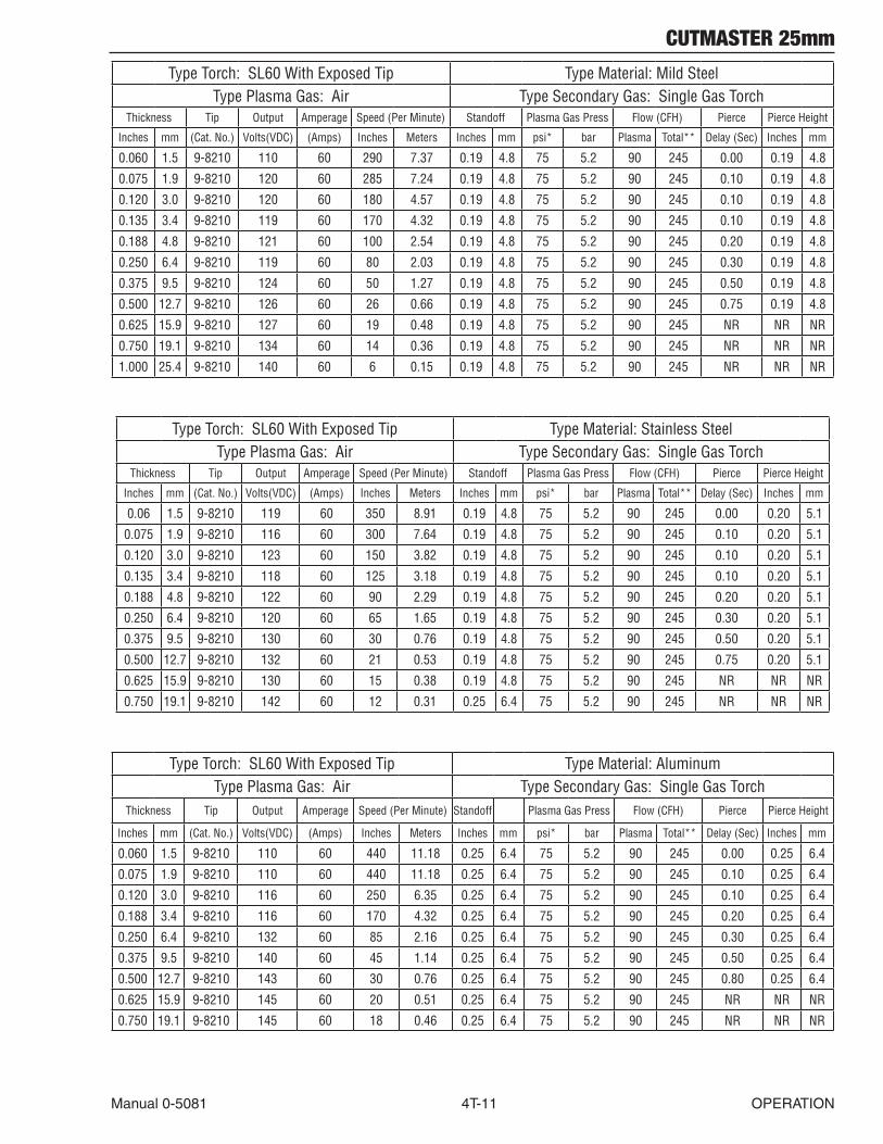
CUTMASTER 25mm
Manual 0-5081 4T-11 OPERATION
Type Torch: SL60 With Exposed Tip Type Material: Mild SteelType Plasma Gas: Air Type Secondary Gas: Single Gas Torch
Thickness Tip Output Amperage Speed (Per Minute) Standoff Plasma Gas Press Flow (CFH) Pierce Pierce Height
Inches mm (Cat. No.) Volts(VDC) (Amps) Inches Meters Inches mm psi* bar Plasma Total** Delay (Sec) Inches mm
0.060 1.5 9-8210 110 60 290 7.37 0.19 4.8 75 5.2 90 245 0.00 0.19 4.8
0.075 1.9 9-8210 120 60 285 7.24 0.19 4.8 75 5.2 90 245 0.10 0.19 4.8
0.120 3.0 9-8210 120 60 180 4.57 0.19 4.8 75 5.2 90 245 0.10 0.19 4.8
0.135 3.4 9-8210 119 60 170 4.32 0.19 4.8 75 5.2 90 245 0.10 0.19 4.8
0.188 4.8 9-8210 121 60 100 2.54 0.19 4.8 75 5.2 90 245 0.20 0.19 4.8
0.250 6.4 9-8210 119 60 80 2.03 0.19 4.8 75 5.2 90 245 0.30 0.19 4.8
0.375 9.5 9-8210 124 60 50 1.27 0.19 4.8 75 5.2 90 245 0.50 0.19 4.8
0.500 12.7 9-8210 126 60 26 0.66 0.19 4.8 75 5.2 90 245 0.75 0.19 4.8
0.625 15.9 9-8210 127 60 19 0.48 0.19 4.8 75 5.2 90 245 NR NR NR
0.750 19.1 9-8210 134 60 14 0.36 0.19 4.8 75 5.2 90 245 NR NR NR
1.000 25.4 9-8210 140 60 6 0.15 0.19 4.8 75 5.2 90 245 NR NR NR
Type Torch: SL60 With Exposed Tip Type Material: Stainless SteelType Plasma Gas: Air Type Secondary Gas: Single Gas Torch
Thickness Tip Output Amperage Speed (Per Minute) Standoff Plasma Gas Press Flow (CFH) Pierce Pierce Height
Inches mm (Cat. No.) Volts(VDC) (Amps) Inches Meters Inches mm psi* bar Plasma Total** Delay (Sec) Inches mm
0.06 1.5 9-8210 119 60 350 8.91 0.19 4.8 75 5.2 90 245 0.00 0.20 5.1
0.075 1.9 9-8210 116 60 300 7.64 0.19 4.8 75 5.2 90 245 0.10 0.20 5.1
0.120 3.0 9-8210 123 60 150 3.82 0.19 4.8 75 5.2 90 245 0.10 0.20 5.1
0.135 3.4 9-8210 118 60 125 3.18 0.19 4.8 75 5.2 90 245 0.10 0.20 5.1
0.188 4.8 9-8210 122 60 90 2.29 0.19 4.8 75 5.2 90 245 0.20 0.20 5.1
0.250 6.4 9-8210 120 60 65 1.65 0.19 4.8 75 5.2 90 245 0.30 0.20 5.1
0.375 9.5 9-8210 130 60 30 0.76 0.19 4.8 75 5.2 90 245 0.50 0.20 5.1
0.500 12.7 9-8210 132 60 21 0.53 0.19 4.8 75 5.2 90 245 0.75 0.20 5.1
0.625 15.9 9-8210 130 60 15 0.38 0.19 4.8 75 5.2 90 245 NR NR NR
0.750 19.1 9-8210 142 60 12 0.31 0.25 6.4 75 5.2 90 245 NR NR NR
Type Torch: SL60 With Exposed Tip Type Material: AluminumType Plasma Gas: Air Type Secondary Gas: Single Gas Torch
Thickness Tip Output Amperage Speed (Per Minute) Standoff Plasma Gas Press Flow (CFH) Pierce Pierce Height
Inches mm (Cat. No.) Volts(VDC) (Amps) Inches Meters Inches mm psi* bar Plasma Total** Delay (Sec) Inches mm
0.060 1.5 9-8210 110 60 440 11.18 0.25 6.4 75 5.2 90 245 0.00 0.25 6.4
0.075 1.9 9-8210 110 60 440 11.18 0.25 6.4 75 5.2 90 245 0.10 0.25 6.4
0.120 3.0 9-8210 116 60 250 6.35 0.25 6.4 75 5.2 90 245 0.10 0.25 6.4
0.188 3.4 9-8210 116 60 170 4.32 0.25 6.4 75 5.2 90 245 0.20 0.25 6.4
0.250 6.4 9-8210 132 60 85 2.16 0.25 6.4 75 5.2 90 245 0.30 0.25 6.4
0.375 9.5 9-8210 140 60 45 1.14 0.25 6.4 75 5.2 90 245 0.50 0.25 6.4
0.500 12.7 9-8210 143 60 30 0.76 0.25 6.4 75 5.2 90 245 0.80 0.25 6.4
0.625 15.9 9-8210 145 60 20 0.51 0.25 6.4 75 5.2 90 245 NR NR NR
0.750 19.1 9-8210 145 60 18 0.46 0.25 6.4 75 5.2 90 245 NR NR NR

CUTMASTER 25mm
OPERATION 4T-12 Manual 0-5081
Type Torch: SL60 With Exposed Tip Type Material: Mild SteelType Plasma Gas: Air Type Secondary Gas: Single Gas Torch
Thickness Tip Output Amperage Speed (Per Minute) Standoff Plasma Gas Press Flow (CFH) Pierce Pierce Height
Inches mm (Cat. No.) Volts(VDC) (Amps) Inches Meters Inches mm psi* bar Plasma Total** Delay (Sec) Inches mm
0.060 1.5 9-8211 113 80 320 8.13 0.19 4.8 70 4.8 115 340 0.00 0.19 4.8
0.120 3.0 9-8211 113 80 230 5.84 0.19 4.8 70 4.8 115 340 0.10 0.19 4.8
0.135 3.4 9-8211 115 80 180 4.57 0.19 4.8 70 4.8 115 340 0.10 0.19 4.8
0.188 4.8 9-8211 114 80 140 3.56 0.19 4.8 70 4.8 115 340 0.20 0.19 4.8
0.250 6.4 9-8211 114 80 100 2.54 0.19 4.8 70 4.8 115 340 0.30 0.19 4.8
0.375 9.5 9-8211 117 80 42 1.07 0.19 4.8 70 4.8 115 340 0.40 0.19 4.8
0.500 12.7 9-8211 120 80 33 0.84 0.19 4.8 70 4.8 115 340 0.60 0.19 4.8
0.625 15.9 9-8211 133 80 22 0.56 0.19 4.8 70 4.8 115 340 0.75 0.19 4.8
0.750 19.1 9-8211 128 80 18 0.46 0.19 4.8 70 4.8 115 340 NR NR NR
0.875 22.2 9-8211 133 80 10 0.25 0.19 4.8 70 4.8 115 340 NR NR NR
1.000 25.4 9-8211 132 80 9 0.23 0.19 4.8 70 4.8 115 340 NR NR NR
Type Torch: SL60 With Exposed Tip Type Material: Stainless SteelType Plasma Gas: Air Type Secondary Gas: Single Gas Torch
Thickness Tip Output Amperage Speed (Per Minute) Standoff Plasma Gas Press Flow (CFH) Pierce Pierce Height
Inches mm (Cat. No.) Volts(VDC) (Amps) Inches Meters Inches mm psi* bar Plasma Total** Delay (Sec) Inches mm
0.060 1.5 9-8211 120 80 340 8.64 0.25 6.4 70 4.8 115 340 0.00 0.25 6.4
0.120 3.0 9-8211 120 80 300 7.62 0.25 6.4 70 4.8 115 340 0.10 0.25 6.4
0.135 3.4 9-8211 120 80 280 7.11 0.25 6.4 70 4.8 115 340 0.10 0.25 6.4
0.188 4.8 9-8211 120 80 140 3.56 0.25 6.4 70 4.8 115 340 0.20 0.25 6.4
0.250 6.4 9-8211 120 80 100 2.54 0.25 6.4 70 4.8 115 340 0.30 0.25 6.4
0.375 9.5 9-8211 126 80 50 1.27 0.25 6.4 70 4.8 115 340 0.40 0.25 6.4
0.500 12.7 9-8211 129 80 28 0.71 0.25 6.4 70 4.8 115 340 0.80 0.25 6.4
0.625 15.9 9-8211 135 80 20 0.51 0.25 6.4 70 4.8 115 340 1.00 0.25 6.4
0.750 19.1 9-8211 143 80 10 0.25 0.25 6.4 70 4.8 115 340 NR NR NR
0.875 22.2 9-8211 143 80 9 0.23 0.25 6.4 70 4.8 115 340 NR NR NR
1.000 25.4 9-8211 146 80 8 0.20 0.25 6.4 70 4.8 115 340 NR NR NR
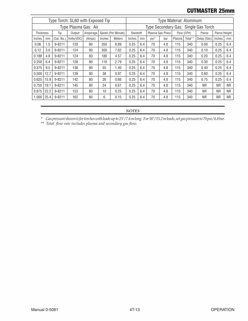
CUTMASTER 25mm
Manual 0-5081 4T-13 OPERATION
Type Torch: SL60 with Exposed Tip Type Material: AluminumType Plasma Gas: Air Type Secondary Gas: Single Gas Torch
Thickness Tip Output Amperage Speed (Per Minute) Standoff Plasma Gas Press Flow (CFH) Pierce Pierce Height
Inches mm (Cat. No.) Volts(VDC) (Amps) Inches Meters Inches mm psi* bar Plasma Total** Delay (Sec) Inches mm
0.06 1.5 9-8211 120 80 350 8.89 0.25 6.4 70 4.8 115 340 0.00 0.25 6.4
0.12 3.0 9-8211 124 80 300 7.62 0.25 6.4 70 4.8 115 340 0.10 0.25 6.4
0.188 4.8 9-8211 124 80 180 4.57 0.25 6.4 70 4.8 115 340 0.20 0.25 6.4
0.250 6.4 9-8211 128 80 110 2.79 0.25 6.4 70 4.8 115 340 0.30 0.25 6.4
0.375 9.5 9-8211 136 80 55 1.40 0.25 6.4 70 4.8 115 340 0.40 0.25 6.4
0.500 12.7 9-8211 139 80 38 0.97 0.25 6.4 70 4.8 115 340 0.60 0.25 6.4
0.625 15.9 9-8211 142 80 26 0.66 0.25 6.4 70 4.8 115 340 0.75 0.25 6.4
0.750 19.1 9-8211 145 80 24 0.61 0.25 6.4 70 4.8 115 340 NR NR NR
0.875 22.2 9-8211 153 80 10 0.25 0.25 6.4 70 4.8 115 340 NR NR NR
1.000 25.4 9-8211 162 80 6 0.15 0.25 6.4 70 4.8 115 340 NR NR NR
NOTES
* Gas pressure shown is for torches with leads up to 25’ / 7.6 m long. For 50’ / 15.2 m leads, set gas pressure to 70 psi / 4.8 bar. ** Total flow rate includes plasma and secondary gas flow.
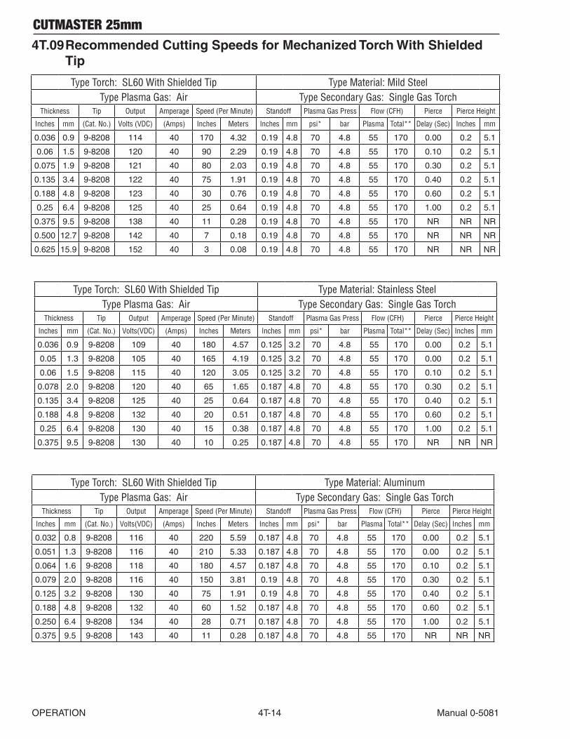
CUTMASTER 25mm
OPERATION 4T-14 Manual 0-5081
4T.09 Recommended Cutting Speeds for Mechanized Torch With Shielded Tip
Type Torch: SL60 With Shielded Tip Type Material: Mild SteelType Plasma Gas: Air Type Secondary Gas: Single Gas Torch
Thickness Tip Output Amperage Speed (Per Minute) Standoff Plasma Gas Press Flow (CFH) Pierce Pierce Height
Inches mm (Cat. No.) Volts (VDC) (Amps) Inches Meters Inches mm psi* bar Plasma Total** Delay (Sec) Inches mm
0.036 0.9 9-8208 114 40 170 4.32 0.19 4.8 70 4.8 55 170 0.00 0.2 5.1
0.06 1.5 9-8208 120 40 90 2.29 0.19 4.8 70 4.8 55 170 0.10 0.2 5.1
0.075 1.9 9-8208 121 40 80 2.03 0.19 4.8 70 4.8 55 170 0.30 0.2 5.1
0.135 3.4 9-8208 122 40 75 1.91 0.19 4.8 70 4.8 55 170 0.40 0.2 5.1
0.188 4.8 9-8208 123 40 30 0.76 0.19 4.8 70 4.8 55 170 0.60 0.2 5.1
0.25 6.4 9-8208 125 40 25 0.64 0.19 4.8 70 4.8 55 170 1.00 0.2 5.1
0.375 9.5 9-8208 138 40 11 0.28 0.19 4.8 70 4.8 55 170 NR NR NR
0.500 12.7 9-8208 142 40 7 0.18 0.19 4.8 70 4.8 55 170 NR NR NR
0.625 15.9 9-8208 152 40 3 0.08 0.19 4.8 70 4.8 55 170 NR NR NR
Type Torch: SL60 With Shielded Tip Type Material: Stainless SteelType Plasma Gas: Air Type Secondary Gas: Single Gas Torch
Thickness Tip Output Amperage Speed (Per Minute) Standoff Plasma Gas Press Flow (CFH) Pierce Pierce Height
Inches mm (Cat. No.) Volts(VDC) (Amps) Inches Meters Inches mm psi* bar Plasma Total** Delay (Sec) Inches mm
0.036 0.9 9-8208 109 40 180 4.57 0.125 3.2 70 4.8 55 170 0.00 0.2 5.1
0.05 1.3 9-8208 105 40 165 4.19 0.125 3.2 70 4.8 55 170 0.00 0.2 5.1
0.06 1.5 9-8208 115 40 120 3.05 0.125 3.2 70 4.8 55 170 0.10 0.2 5.1
0.078 2.0 9-8208 120 40 65 1.65 0.187 4.8 70 4.8 55 170 0.30 0.2 5.1
0.135 3.4 9-8208 125 40 25 0.64 0.187 4.8 70 4.8 55 170 0.40 0.2 5.1
0.188 4.8 9-8208 132 40 20 0.51 0.187 4.8 70 4.8 55 170 0.60 0.2 5.1
0.25 6.4 9-8208 130 40 15 0.38 0.187 4.8 70 4.8 55 170 1.00 0.2 5.1
0.375 9.5 9-8208 130 40 10 0.25 0.187 4.8 70 4.8 55 170 NR NR NR
Type Torch: SL60 With Shielded Tip Type Material: AluminumType Plasma Gas: Air Type Secondary Gas: Single Gas Torch
Thickness Tip Output Amperage Speed (Per Minute) Standoff Plasma Gas Press Flow (CFH) Pierce Pierce Height
Inches mm (Cat. No.) Volts(VDC) (Amps) Inches Meters Inches mm psi* bar Plasma Total** Delay (Sec) Inches mm
0.032 0.8 9-8208 116 40 220 5.59 0.187 4.8 70 4.8 55 170 0.00 0.2 5.1
0.051 1.3 9-8208 116 40 210 5.33 0.187 4.8 70 4.8 55 170 0.00 0.2 5.1
0.064 1.6 9-8208 118 40 180 4.57 0.187 4.8 70 4.8 55 170 0.10 0.2 5.1
0.079 2.0 9-8208 116 40 150 3.81 0.19 4.8 70 4.8 55 170 0.30 0.2 5.1
0.125 3.2 9-8208 130 40 75 1.91 0.19 4.8 70 4.8 55 170 0.40 0.2 5.1
0.188 4.8 9-8208 132 40 60 1.52 0.187 4.8 70 4.8 55 170 0.60 0.2 5.1
0.250 6.4 9-8208 134 40 28 0.71 0.187 4.8 70 4.8 55 170 1.00 0.2 5.1
0.375 9.5 9-8208 143 40 11 0.28 0.187 4.8 70 4.8 55 170 NR NR NR

CUTMASTER 25mm
Manual 0-5081 4T-15 OPERATION
Type Torch: SL60 With Shielded Tip Type Material: Mild SteelType Plasma Gas: Air Type Secondary Gas: Single Gas Torch
Thickness Tip Output Amperage Speed (Per Minute) Standoff Plasma Gas Press Flow (CFH) Pierce Pierce Height
Inches mm (Cat. No.) Volts (VDC) (Amps) Inches Meters Inches mm psi* bar Plasma Total** Delay (Sec) Inches mm
0.060 1.5 9-8210 124 60 250 6.35 0.19 4.8 75 5.2 90 245 0.00 0.2 5.1
0.075 1.9 9-8210 126 60 237 6.02 0.19 4.8 75 5.2 90 245 0.10 0.2 5.1
0.120 3.0 9-8210 126 60 230 5.84 0.19 4.8 75 5.2 90 245 0.10 0.2 5.1
0.135 3.4 9-8210 128 60 142 3.61 0.19 4.8 75 5.2 90 245 0.10 0.2 5.1
0.188 4.8 9-8210 128 60 125 3.18 0.19 4.8 75 5.2 90 245 0.20 0.2 5.1
0.250 6.4 9-8210 123 60 80 2.03 0.19 4.8 75 5.2 90 245 0.30 0.2 5.1
0.375 9.5 9-8210 132 60 34 0.86 0.19 4.8 75 5.2 90 245 0.50 0.2 5.1
0.500 12.7 9-8210 137 60 23 0.58 0.19 4.8 75 5.2 90 245 0.75 0.2 5.1
0.625 15.9 9-8210 139 60 14 0.36 0.19 4.8 75 5.2 90 245 NR NR NR
0.750 19.1 9-8210 145 60 14 0.36 0.19 4.8 75 5.2 90 245 NR NR NR
1.000 25.4 9-8210 156 60 4 0.10 0.19 4.8 75 5.2 90 245 NR NR NR
Type Torch: SL60 With Shielded Tip Type Material: Stainless SteelType Plasma Gas: Air Type Secondary Gas: Single Gas Torch
Thickness Tip Output Amperage Speed (Per Minute) Standoff Plasma Gas Press Flow (CFH) Pierce Pierce Height
Inches mm (Cat. No.) Volts(VDC) (Amps) Inches Meters Inches mm psi* bar Plasma Total** Delay (Sec) Inches mm
0.06 1.5 9-8210 110 60 165 4.19 0.13 3.2 75 5.2 90 245 0.00 0.20 5.1
0.075 1.9 9-8210 116 60 155 3.94 0.13 3.2 75 5.2 90 245 0.10 0.20 5.1
0.120 3.0 9-8210 115 60 125 3.18 0.13 3.2 75 5.2 90 245 0.10 0.20 5.1
0.135 3.4 9-8210 118 60 80 2.03 0.13 3.2 75 5.2 90 245 0.10 0.20 5.1
0.188 4.8 9-8210 120 60 75 1.91 0.13 3.2 75 5.2 90 245 0.20 0.20 5.1
0.250 6.4 9-8210 121 60 60 1.52 0.13 3.2 75 5.2 90 245 0.30 0.20 5.1
0.375 9.5 9-8210 129 60 28 0.71 0.13 3.2 75 5.2 90 245 0.50 0.20 5.1
0.500 12.7 9-8210 135 60 17 0.43 0.19 4.8 75 5.2 90 245 0.75 0.20 5.1
0.625 15.9 9-8210 135 60 14 0.36 0.19 4.8 75 5.2 90 245 NR NR NR
0.750 19.1 9-8210 142 60 10 0.25 0.19 4.8 75 5.2 90 245 NR NR NR
Type Torch: SL60 With Shielded Tip Type Material: Aluminum
Type Plasma Gas: Air Type Secondary Gas: Single Gas TorchThickness Tip Output Amperage Speed (Per Minute) Standoff Plasma Gas Press Flow (CFH) Pierce Pierce Height
Inches mm (Cat. No.) Volts(VDC) (Amps) Inches Meters Inches mm psi* bar Plasma Total** Delay (Sec) Inches mm
0.060 1.5 9-8210 105 60 350 8.89 0.13 3.2 75 5.2 90 245 0.00 0.20 5.1
0.075 1.9 9-8210 110 60 350 8.89 0.13 3.2 75 5.2 90 245 0.10 0.20 5.1
0.120 3.0 9-8210 110 60 275 6.99 0.13 3.2 75 5.2 90 245 0.10 0.20 5.1
0.188 3.4 9-8210 122 60 140 3.56 0.13 3.2 75 5.2 90 245 0.20 0.20 5.1
0.250 6.4 9-8210 134 60 80 2.03 0.19 4.8 75 5.2 90 245 0.30 0.20 5.1
0.375 9.5 9-8210 140 60 45 1.14 0.19 4.8 75 5.2 90 245 0.50 0.20 5.1
0.500 12.7 9-8210 144 60 26 0.66 0.19 4.8 75 5.2 90 245 0.80 0.20 5.1
0.625 15.9 9-8210 145 60 19 0.48 0.19 4.8 75 5.2 90 245 NR NR NR
0.750 19.1 9-8210 150 60 15 0.38 0.19 4.8 75 5.2 90 245 NR NR NR
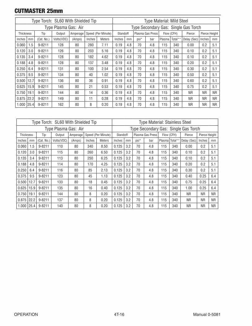
CUTMASTER 25mm
OPERATION 4T-16 Manual 0-5081
Type Torch: SL60 With Shielded Tip Type Material: Mild SteelType Plasma Gas: Air Type Secondary Gas: Single Gas Torch
Thickness Tip Output Amperage Speed (Per Minute) Standoff Plasma Gas Press Flow (CFH) Pierce Pierce Height
Inches mm (Cat. No.) Volts(VDC) (Amps) Inches Meters Inches mm psi* bar Plasma Total** Delay (Sec) Inches mm
0.060 1.5 9-8211 128 80 280 7.11 0.19 4.8 70 4.8 115 340 0.00 0.2 5.1
0.120 3.0 9-8211 126 80 203 5.16 0.19 4.8 70 4.8 115 340 0.10 0.2 5.1
0.135 3.4 9-8211 128 80 182 4.62 0.19 4.8 70 4.8 115 340 0.10 0.2 5.1
0.188 4.8 9-8211 128 80 137 3.48 0.19 4.8 70 4.8 115 340 0.20 0.2 5.1
0.250 6.4 9-8211 131 80 100 2.54 0.19 4.8 70 4.8 115 340 0.30 0.2 5.1
0.375 9.5 9-8211 134 80 40 1.02 0.19 4.8 70 4.8 115 340 0.50 0.2 5.1
0.500 12.7 9-8211 136 80 36 0.91 0.19 4.8 70 4.8 115 340 0.60 0.2 5.1
0.625 15.9 9-8211 145 80 21 0.53 0.19 4.8 70 4.8 115 340 0.75 0.2 5.1
0.750 19.1 9-8211 144 80 14 0.36 0.19 4.8 70 4.8 115 340 NR NR NR
0.875 22.2 9-8211 149 80 11 0.28 0.19 4.8 70 4.8 115 340 NR NR NR
1.000 25.4 9-8211 162 80 8 0.20 0.19 4.8 70 4.8 115 340 NR NR NR
Type Torch: SL60 With Shielded Tip Type Material: Stainless SteelType Plasma Gas: Air Type Secondary Gas: Single Gas Torch
Thickness Tip Output Amperage Speed (Per Minute) Standoff Plasma Gas Press Flow (CFH) Pierce Pierce Height
Inches mm (Cat. No.) Volts(VDC) (Amps) Inches Meters Inches mm psi* bar Plasma Total** Delay (Sec) Inches mm
0.060 1.5 9-8211 110 80 340 8.50 0.125 3.2 70 4.8 115 340 0.00 0.2 5.1
0.120 3.0 9-8211 115 80 260 6.50 0.125 3.2 70 4.8 115 340 0.10 0.2 5.1
0.135 3.4 9-8211 113 80 250 6.25 0.125 3.2 70 4.8 115 340 0.10 0.2 5.1
0.188 4.8 9-8211 114 80 170 4.25 0.125 3.2 70 4.8 115 340 0.20 0.2 5.1
0.250 6.4 9-8211 116 80 85 2.13 0.125 3.2 70 4.8 115 340 0.30 0.2 5.1
0.375 9.5 9-8211 123 80 45 1.13 0.125 3.2 70 4.8 115 340 0.40 0.25 6.4
0.500 12.7 9-8211 133 80 18 0.45 0.125 3.2 70 4.8 115 340 0.75 0.25 6.4
0.625 15.9 9-8211 135 80 16 0.40 0.125 3.2 70 4.8 115 340 1.00 0.25 6.4
0.750 19.1 9-8211 144 80 8 0.20 0.125 3.2 70 4.8 115 340 NR NR NR
0.875 22.2 9-8211 137 80 8 0.20 0.125 3.2 70 4.8 115 340 NR NR NR
1.000 25.4 9-8211 140 80 8 0.20 0.125 3.2 70 4.8 115 340 NR NR NR

CUTMASTER 25mm
Manual 0-5081 4T-17 OPERATION
Type Torch: SL60 With Shielded Tip Type Material: AluminumType Plasma Gas: Air Type Secondary Gas: Single Gas Torch
Thickness Tip Output Amperage Speed (Per Minute) Standoff Plasma Gas Press Flow (CFH) Pierce Pierce Height
Inches mm (Cat. No.) Volts(VDC) (Amps) Inches Meters Inches mm psi* bar Plasma Total** Delay (Sec) Inches mm
0.06 1.5 9-8211 115 80 320 8.13 0.13 3.2 70 4.8 115 340 0.00 0.25 6.4
0.12 3.0 9-8211 120 80 240 6.10 0.13 3.2 70 4.8 115 340 0.10 0.25 6.4
0.188 4.8 9-8211 120 80 165 4.19 0.13 3.2 70 4.8 115 340 0.20 0.25 6.4
0.250 6.4 9-8211 124 80 100 2.54 0.13 3.2 70 4.8 115 340 0.30 0.25 6.4
0.375 9.5 9-8211 138 80 60 1.52 0.19 4.8 70 4.8 115 340 0.40 0.25 6.4
0.500 12.7 9-8211 141 80 36 0.91 0.19 4.8 70 4.8 115 340 0.60 0.25 6.4
0.625 15.9 9-8211 142 80 26 0.66 0.19 4.8 70 4.8 115 340 0.75 0.25 6.4
0.750 19.1 9-8211 150 80 18 0.46 0.19 4.8 70 4.8 115 340 NR NR NR
0.875 22.2 9-8211 156 80 8 0.20 0.19 4.8 70 4.8 115 340 NR NR NR
1.000 25.4 9-8211 164 80 6 0.15 0.19 4.8 70 4.8 115 340 NR NR NR
NOTES
* Gas pressure shown is for torches with leads up to 25’ / 7.6 m long. For 50’ / 15.2 m leads, set gas pressure to 70 psi / 4.8 bar. ** Total flow rate includes plasma and secondary gas flow.
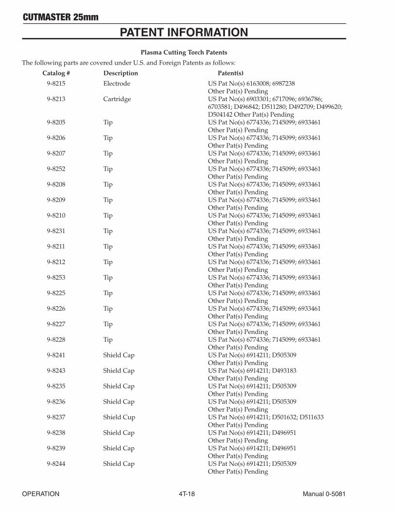
CUTMASTER 25mm
OPERATION 4T-18 Manual 0-5081
PATENT INFORMATION
Plasma Cutting Torch Patents
The following parts are covered under U.S. and Foreign Patents as follows:
Catalog # Description Patent(s)
9-8215 Electrode US Pat No(s) 6163008; 6987238 Other Pat(s) Pending 9-8213 Cartridge US Pat No(s) 6903301; 6717096; 6936786; 6703581; D496842; D511280; D492709; D499620; D504142 Other Pat(s) Pending 9-8205 Tip US Pat No(s) 6774336; 7145099; 6933461 Other Pat(s) Pending 9-8206 Tip US Pat No(s) 6774336; 7145099; 6933461 Other Pat(s) Pending 9-8207 Tip US Pat No(s) 6774336; 7145099; 6933461 Other Pat(s) Pending 9-8252 Tip US Pat No(s) 6774336; 7145099; 6933461 Other Pat(s) Pending 9-8208 Tip US Pat No(s) 6774336; 7145099; 6933461 Other Pat(s) Pending 9-8209 Tip US Pat No(s) 6774336; 7145099; 6933461 Other Pat(s) Pending 9-8210 Tip US Pat No(s) 6774336; 7145099; 6933461 Other Pat(s) Pending 9-8231 Tip US Pat No(s) 6774336; 7145099; 6933461 Other Pat(s) Pending 9-8211 Tip US Pat No(s) 6774336; 7145099; 6933461 Other Pat(s) Pending 9-8212 Tip US Pat No(s) 6774336; 7145099; 6933461 Other Pat(s) Pending 9-8253 Tip US Pat No(s) 6774336; 7145099; 6933461 Other Pat(s) Pending 9-8225 Tip US Pat No(s) 6774336; 7145099; 6933461 Other Pat(s) Pending 9-8226 Tip US Pat No(s) 6774336; 7145099; 6933461 Other Pat(s) Pending 9-8227 Tip US Pat No(s) 6774336; 7145099; 6933461 Other Pat(s) Pending 9-8228 Tip US Pat No(s) 6774336; 7145099; 6933461 Other Pat(s) Pending 9-8241 Shield Cap US Pat No(s) 6914211; D505309 Other Pat(s) Pending 9-8243 Shield Cap US Pat No(s) 6914211; D493183 Other Pat(s) Pending 9-8235 Shield Cap US Pat No(s) 6914211; D505309 Other Pat(s) Pending 9-8236 Shield Cap US Pat No(s) 6914211; D505309 Other Pat(s) Pending 9-8237 Shield Cup US Pat No(s) 6914211; D501632; D511633 Other Pat(s) Pending 9-8238 Shield Cap US Pat No(s) 6914211; D496951 Other Pat(s) Pending 9-8239 Shield Cap US Pat No(s) 6914211; D496951 Other Pat(s) Pending 9-8244 Shield Cap US Pat No(s) 6914211; D505309 Other Pat(s) Pending

CUTMASTER 25mm
Manual 0-5081 4T-19 OPERATION
Catalog # Description Patent(s)
9-8245 Shield Cap US Pat No(s) 6914211; D496951 Other Pat(s) Pending
The following parts are also licensed under U.S. Patent No. 5,120,930 and 5,132,512:
Catalog # Description
9-8235 Shield Cap9-8236 Shield Cap9-8237 Shield Cup9-8238 Shield Cap9-8239 Shield Cap9-8244 Shield Cap9-8245 Shield Cap

CUTMASTER 25mm
OPERATION 4T-20 Manual 0-5081
This Page Intentionally Blank
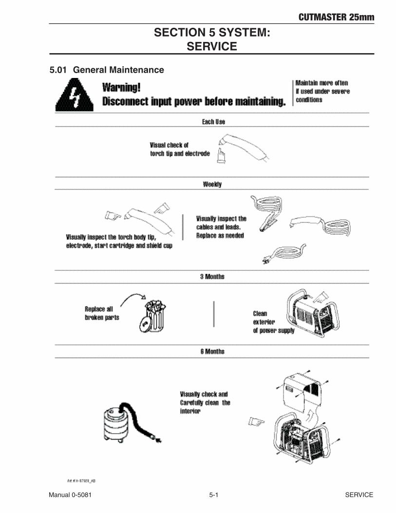
CUTMASTER 25mm
Manual 0-5081 5-1 SERVICE
SECTION 5 SYSTEM: SERVICE
5.01 General Maintenance
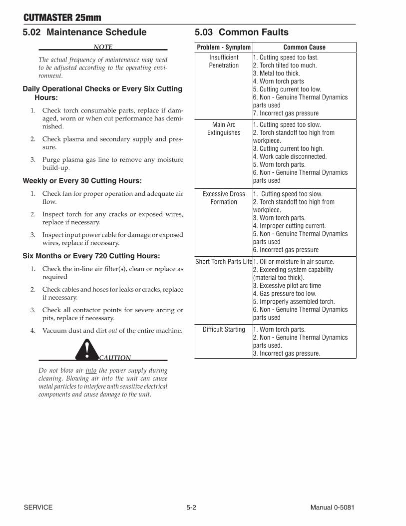
CUTMASTER 25mm
SERVICE 5-2 Manual 0-5081
5.02 Maintenance Schedule
NOTE
The actual frequency of maintenance may need to be adjusted according to the operating envi-ronment.
Daily Operational Checks or Every Six Cutting Hours:
1. Check torch consumable parts, replace if dam-aged, worn or when cut performance has demi-nished.
2. Check plasma and secondary supply and pres-sure.
3. Purge plasma gas line to remove any moisture build-up.
Weekly or Every 30 Cutting Hours:
1. Check fan for proper operation and adequate air flow.
2. Inspect torch for any cracks or exposed wires, replace if necessary.
3. Inspect input power cable for damage or exposed wires, replace if necessary.
Six Months or Every 720 Cutting Hours:
1. Check the in-line air filter(s), clean or replace as required
2. Check cables and hoses for leaks or cracks, replace if necessary.
3. Check all contactor points for severe arcing or pits, replace if necessary.
4. Vacuum dust and dirt out of the entire machine.
CAUTION
Do not blow air into the power supply during cleaning. Blowing air into the unit can cause metal particles to interfere with sensitive electrical components and cause damage to the unit.
5.03 Common Faults
Problem - Symptom Common CauseInsufficient Penetration
1. Cutting speed too fast. 2. Torch tilted too much. 3. Metal too thick. 4. Worn torch parts 5. Cutting current too low. 6. Non - Genuine Thermal Dynamics parts used 7. Incorrect gas pressure
Main Arc Extinguishes
1. Cutting speed too slow. 2. Torch standoff too high from workpiece. 3. Cutting current too high. 4. Work cable disconnected. 5. Worn torch parts. 6. Non - Genuine Thermal Dynamics parts used
Excessive Dross Formation
1. Cutting speed too slow. 2. Torch standoff too high from workpiece. 3. Worn torch parts. 4. Improper cutting current. 5. Non - Genuine Thermal Dynamics parts used 6. Incorrect gas pressure
Short Torch Parts Life1. Oil or moisture in air source. 2. Exceeding system capability (material too thick). 3. Excessive pilot arc time 4. Gas pressure too low. 5. Improperly assembled torch. 6. Non - Genuine Thermal Dynamics parts used
Difficult Starting 1. Worn torch parts. 2. Non - Genuine Thermal Dynamics parts used. 3. Incorrect gas pressure.
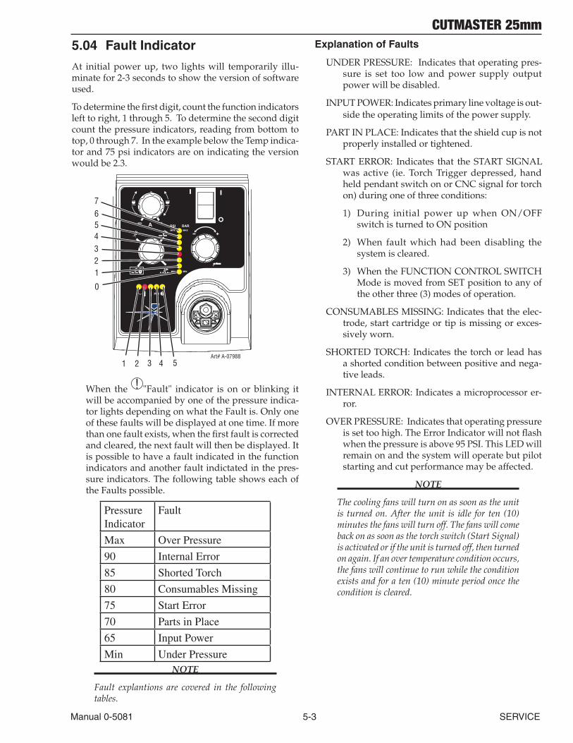
CUTMASTER 25mm
Manual 0-5081 5-3 SERVICE
5.04 Fault Indicator
At initial power up, two lights will temporarily illu-minate for 2-3 seconds to show the version of software used.
To determine the first digit, count the function indicators left to right, 1 through 5. To determine the second digit count the pressure indicators, reading from bottom to top, 0 through 7. In the example below the Temp indica-tor and 75 psi indicators are on indicating the version would be 2.3.
A+
PSI BARMAX MAX
MIN MIN
!
1 2 3 4Art# A-07988
MIN MAX
0
1234567
5
When the ! "Fault" indicator is on or blinking it will be accompanied by one of the pressure indica-tor lights depending on what the Fault is. Only one of these faults will be displayed at one time. If more than one fault exists, when the first fault is corrected and cleared, the next fault will then be displayed. It is possible to have a fault indicated in the function indicators and another fault indictated in the pres-sure indicators. The following table shows each of the Faults possible.
Pressure Indicator
Fault
Max Over Pressure
90 Internal Error
85 Shorted Torch
80 Consumables Missing
75 Start Error
70 Parts in Place
65 Input Power
Min Under PressureNOTE
Fault explantions are covered in the following tables.
Explanation of Faults
UNDER PRESSURE: Indicates that operating pres-sure is set too low and power supply output power will be disabled.
INPUT POWER: Indicates primary line voltage is out-side the operating limits of the power supply.
PART IN PLACE: Indicates that the shield cup is not properly installed or tightened.
START ERROR: Indicates that the START SIGNAL was active (ie. Torch Trigger depressed, hand held pendant switch on or CNC signal for torch on) during one of three conditions:
1) During initial power up when ON/OFF switch is turned to ON position
2) When fault which had been disabling the system is cleared.
3) When the FUNCTION CONTROL SWITCH Mode is moved from SET position to any of the other three (3) modes of operation.
CONSUMABLES MISSING: Indicates that the elec-trode, start cartridge or tip is missing or exces-sively worn.
SHORTED TORCH: Indicates the torch or lead has a shorted condition between positive and nega-tive leads.
INTERNAL ERROR: Indicates a microprocessor er-ror.
OVER PRESSURE: Indicates that operating pressure is set too high. The Error Indicator will not flash when the pressure is above 95 PSI. This LED will remain on and the system will operate but pilot starting and cut performance may be affected.
NOTE
The cooling fans will turn on as soon as the unit is turned on. After the unit is idle for ten (10) minutes the fans will turn off. The fans will come back on as soon as the torch switch (Start Signal) is activated or if the unit is turned off, then turned on again. If an over temperature condition occurs, the fans will continue to run while the condition exists and for a ten (10) minute period once the condition is cleared.
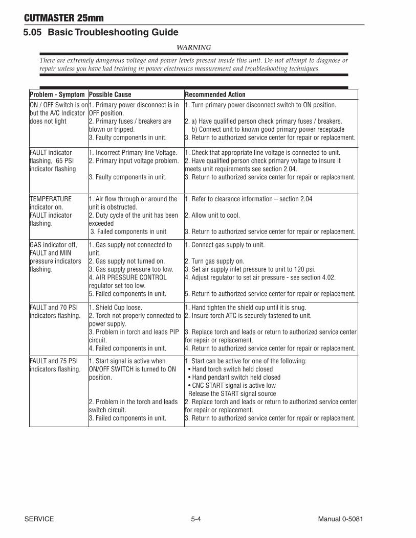
CUTMASTER 25mm
SERVICE 5-4 Manual 0-5081
5.05 Basic Troubleshooting Guide
WARNING
There are extremely dangerous voltage and power levels present inside this unit. Do not attempt to diagnose or repair unless you have had training in power electronics measurement and troubleshooting techniques.
Problem - Symptom Possible Cause Recommended ActionON / OFF Switch is on but the A/C Indicator does not light
1. Primary power disconnect is in OFF position.2. Primary fuses / breakers are blown or tripped.3. Faulty components in unit.
1. Turn primary power disconnect switch to ON position.
2. a) Have qualified person check primary fuses / breakers. b) Connect unit to known good primary power receptacle 3. Return to authorized service center for repair or replacement.
FAULT indicator flashing, 65 PSI indicator flashing
1. Incorrect Primary line Voltage. 2. Primary input voltage problem.
3. Faulty components in unit.
1. Check that appropriate line voltage is connected to unit.2. Have qualified person check primary voltage to insure it meets unit requirements see section 2.04. 3. Return to authorized service center for repair or replacement.
TEMPERATURE indicator on. FAULT indicator flashing.
1. Air flow through or around the unit is obstructed. 2. Duty cycle of the unit has been exceeded 3. Failed components in unit
1. Refer to clearance information – section 2.04
2. Allow unit to cool.
3. Return to authorized service center for repair or replacement.
GAS indicator off, FAULT and MIN pressure indicators flashing.
1. Gas supply not connected to unit.2. Gas supply not turned on. 3. Gas supply pressure too low.4. AIR PRESSURE CONTROL regulator set too low. 5. Failed components in unit.
1. Connect gas supply to unit.
2. Turn gas supply on.3. Set air supply inlet pressure to unit to 120 psi. 4. Adjust regulator to set air pressure - see section 4.02.
5. Return to authorized service center for repair or replacement.
FAULT and 70 PSI indicators flashing.
1. Shield Cup loose. 2. Torch not properly connected to power supply. 3. Problem in torch and leads PIP circuit. 4. Failed components in unit.
1. Hand tighten the shield cup until it is snug. 2. Insure torch ATC is securely fastened to unit.
3. Replace torch and leads or return to authorized service center for repair or replacement. 4. Return to authorized service center for repair or replacement.
FAULT and 75 PSI indicators flashing.
1. Start signal is active when ON/OFF SWITCH is turned to ON position.
2. Problem in the torch and leads switch circuit. 3. Failed components in unit.
1. Start can be active for one of the following: • Hand torch switch held closed • Hand pendant switch held closed • CNC START signal is active low Release the START signal source 2. Replace torch and leads or return to authorized service center for repair or replacement. 3. Return to authorized service center for repair or replacement.
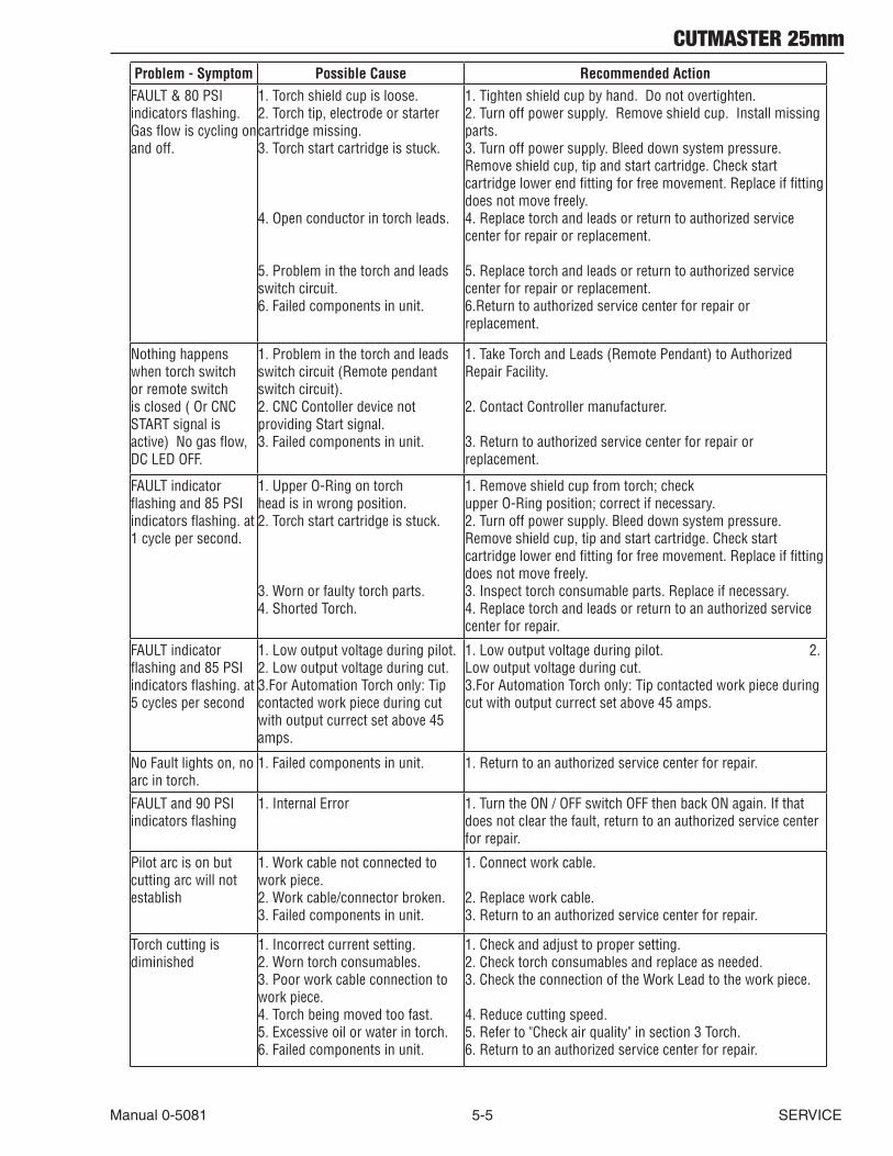
CUTMASTER 25mm
Manual 0-5081 5-5 SERVICE
Problem - Symptom Possible Cause Recommended ActionFAULT & 80 PSI indicators flashing. Gas flow is cycling on and off.
1. Torch shield cup is loose. 2. Torch tip, electrode or starter cartridge missing. 3. Torch start cartridge is stuck. 4. Open conductor in torch leads. 5. Problem in the torch and leads switch circuit. 6. Failed components in unit.
1. Tighten shield cup by hand. Do not overtighten. 2. Turn off power supply. Remove shield cup. Install missing parts. 3. Turn off power supply. Bleed down system pressure. Remove shield cup, tip and start cartridge. Check start cartridge lower end fitting for free movement. Replace if fitting does not move freely. 4. Replace torch and leads or return to authorized service center for repair or replacement. 5. Replace torch and leads or return to authorized service center for repair or replacement. 6.Return to authorized service center for repair or replacement.
Nothing happens when torch switch or remote switch is closed ( Or CNC START signal is active) No gas flow, DC LED OFF.
1. Problem in the torch and leads switch circuit (Remote pendant switch circuit). 2. CNC Contoller device not providing Start signal. 3. Failed components in unit.
1. Take Torch and Leads (Remote Pendant) to Authorized Repair Facility. 2. Contact Controller manufacturer. 3. Return to authorized service center for repair or replacement.
FAULT indicator flashing and 85 PSI indicators flashing. at 1 cycle per second.
1. Upper O-Ring on torch head is in wrong position. 2. Torch start cartridge is stuck. 3. Worn or faulty torch parts. 4. Shorted Torch.
1. Remove shield cup from torch; check upper O-Ring position; correct if necessary. 2. Turn off power supply. Bleed down system pressure. Remove shield cup, tip and start cartridge. Check start cartridge lower end fitting for free movement. Replace if fitting does not move freely. 3. Inspect torch consumable parts. Replace if necessary. 4. Replace torch and leads or return to an authorized service center for repair.
FAULT indicator flashing and 85 PSI indicators flashing. at 5 cycles per second
1. Low output voltage during pilot. 2. Low output voltage during cut.3.For Automation Torch only: Tip contacted work piece during cut with output currect set above 45 amps.
1. Low output voltage during pilot. 2. Low output voltage during cut.3.For Automation Torch only: Tip contacted work piece during cut with output currect set above 45 amps.
No Fault lights on, no arc in torch.
1. Failed components in unit. 1. Return to an authorized service center for repair.
FAULT and 90 PSI indicators flashing
1. Internal Error 1. Turn the ON / OFF switch OFF then back ON again. If that does not clear the fault, return to an authorized service center for repair.
Pilot arc is on but cutting arc will not establish
1. Work cable not connected to work piece. 2. Work cable/connector broken. 3. Failed components in unit.
1. Connect work cable. 2. Replace work cable. 3. Return to an authorized service center for repair.
Torch cutting is diminished
1. Incorrect current setting. 2. Worn torch consumables. 3. Poor work cable connection to work piece. 4. Torch being moved too fast. 5. Excessive oil or water in torch. 6. Failed components in unit.
1. Check and adjust to proper setting. 2. Check torch consumables and replace as needed. 3. Check the connection of the Work Lead to the work piece. 4. Reduce cutting speed. 5. Refer to "Check air quality" in section 3 Torch. 6. Return to an authorized service center for repair.
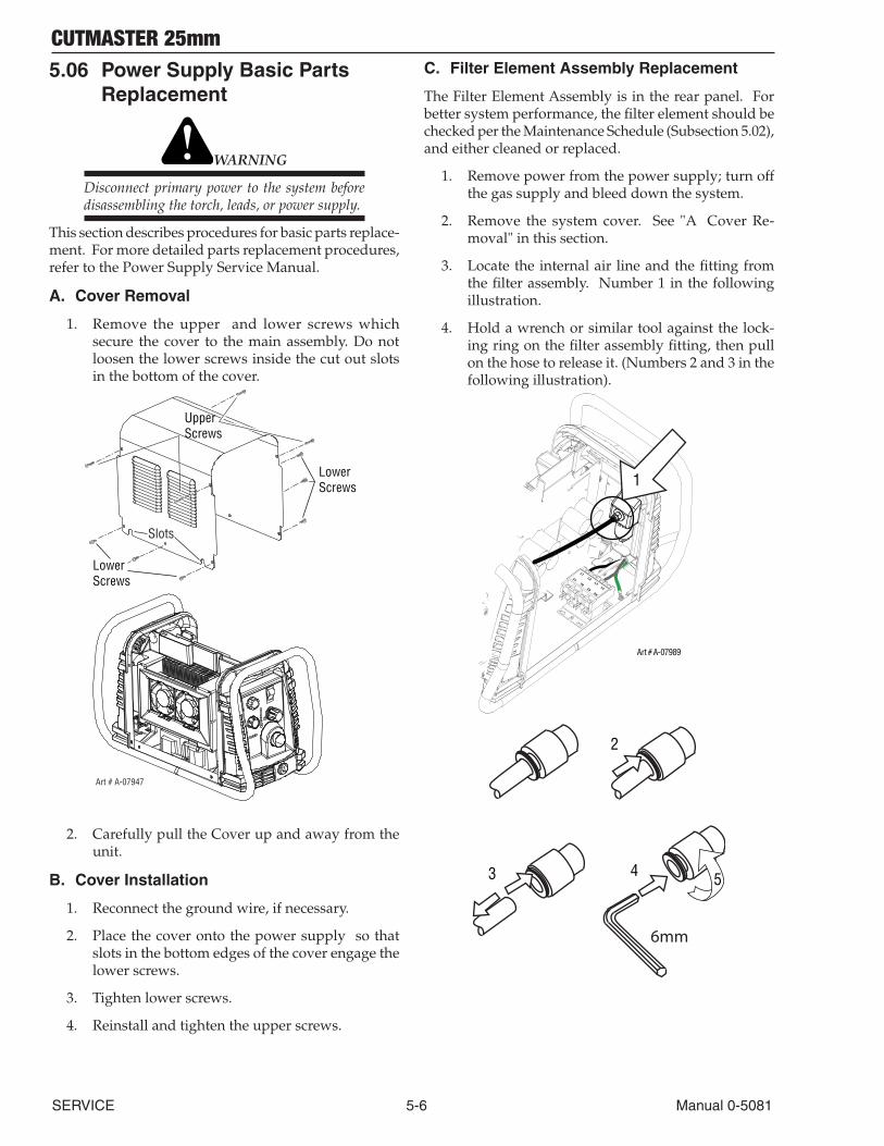
CUTMASTER 25mm
SERVICE 5-6 Manual 0-5081
5.06 Power Supply Basic Parts Replacement
WARNING
Disconnect primary power to the system before disassembling the torch, leads, or power supply.
This section describes procedures for basic parts replace-ment. For more detailed parts replacement procedures, refer to the Power Supply Service Manual.
A. Cover Removal
1. Remove the upper and lower screws which secure the cover to the main assembly. Do not loosen the lower screws inside the cut out slots in the bottom of the cover.
UpperScrews
Lower Screws
Lower Screws
Art # A-07947
Slots
2. Carefully pull the Cover up and away from the unit.
B. Cover Installation
1. Reconnect the ground wire, if necessary.
2. Place the cover onto the power supply so that slots in the bottom edges of the cover engage the lower screws.
3. Tighten lower screws.
4. Reinstall and tighten the upper screws.
C. Filter Element Assembly Replacement
The Filter Element Assembly is in the rear panel. For better system performance, the filter element should be checked per the Maintenance Schedule (Subsection 5.02), and either cleaned or replaced.
1. Remove power from the power supply; turn off the gas supply and bleed down the system.
2. Remove the system cover. See "A Cover Re-moval" in this section.
3. Locate the internal air line and the fitting from the filter assembly. Number 1 in the following illustration.
4. Hold a wrench or similar tool against the lock-ing ring on the filter assembly fitting, then pull on the hose to release it. (Numbers 2 and 3 in the following illustration).
Art # A-07989
1
2
3 4 5
6mm
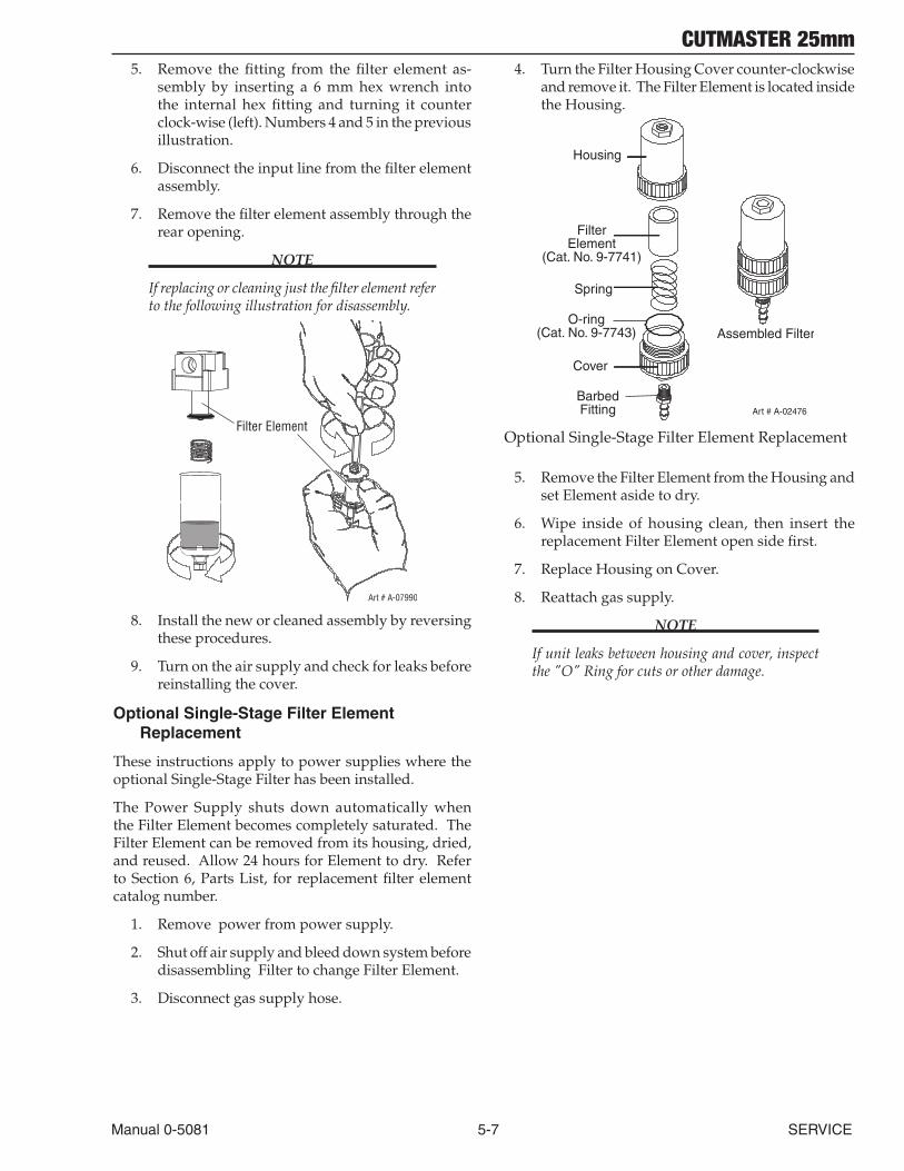
CUTMASTER 25mm
Manual 0-5081 5-7 SERVICE
5. Remove the fitting from the filter element as-sembly by inserting a 6 mm hex wrench into the internal hex fitting and turning it counter clock-wise (left). Numbers 4 and 5 in the previous illustration.
6. Disconnect the input line from the filter element assembly.
7. Remove the filter element assembly through the rear opening.
NOTE
If replacing or cleaning just the filter element refer to the following illustration for disassembly.
Art # A-07990
Filter Element
8. Install the new or cleaned assembly by reversing these procedures.
9. Turn on the air supply and check for leaks before reinstalling the cover.
Optional Single-Stage Filter Element Replacement
These instructions apply to power supplies where the optional Single-Stage Filter has been installed.
The Power Supply shuts down automatically when the Filter Element becomes completely saturated. The Filter Element can be removed from its housing, dried, and reused. Allow 24 hours for Element to dry. Refer to Section 6, Parts List, for replacement filter element catalog number.
1. Remove power from power supply.
2. Shut off air supply and bleed down system before disassembling Filter to change Filter Element.
3. Disconnect gas supply hose.
4. Turn the Filter Housing Cover counter-clockwise and remove it. The Filter Element is located inside the Housing.
Art # A-02476
FilterElement
(Cat. No. 9-7741)
Housing
Cover
BarbedFitting
Spring
Assembled FilterO-ring
(Cat. No. 9-7743)
Optional Single-Stage Filter Element Replacement
5. Remove the Filter Element from the Housing and set Element aside to dry.
6. Wipe inside of housing clean, then insert the replacement Filter Element open side first.
7. Replace Housing on Cover.
8. Reattach gas supply.
NOTE
If unit leaks between housing and cover, inspect the "O" Ring for cuts or other damage.
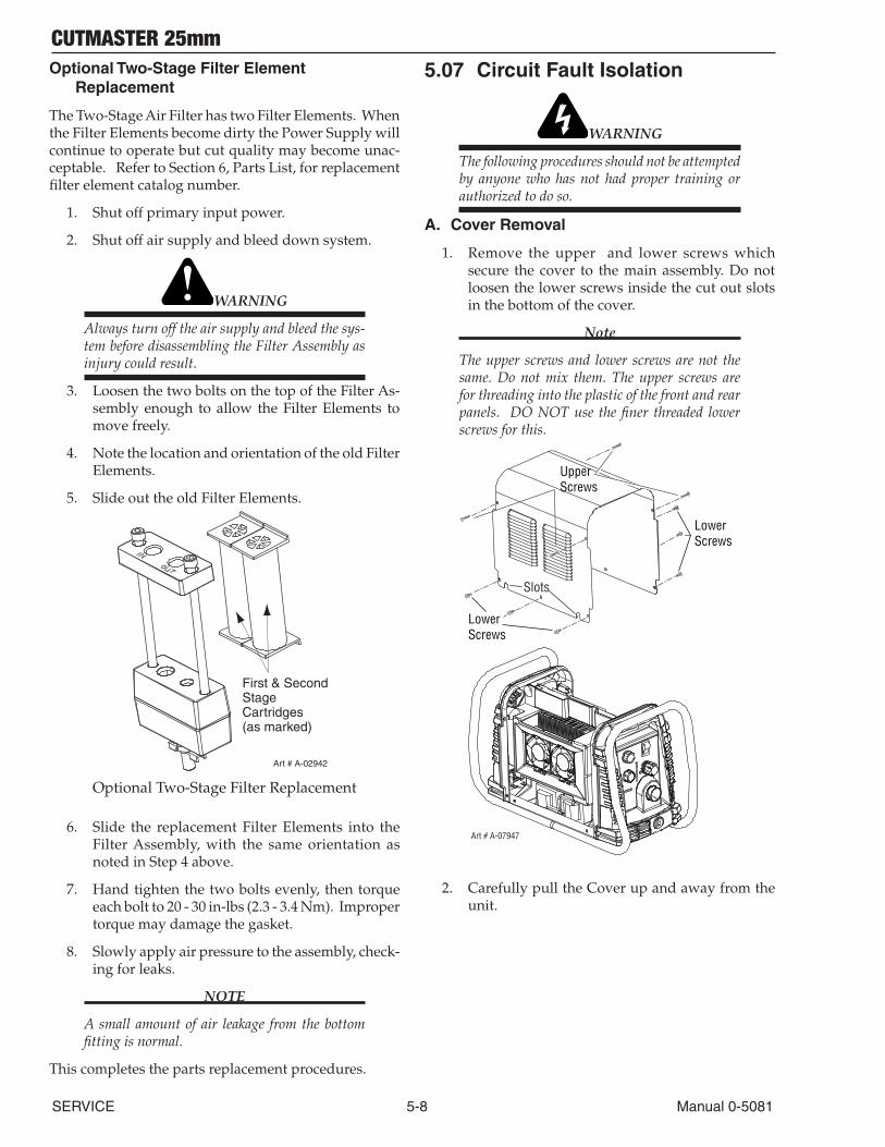
CUTMASTER 25mm
SERVICE 5-8 Manual 0-5081
Optional Two-Stage Filter Element Replacement
The Two-Stage Air Filter has two Filter Elements. When the Filter Elements become dirty the Power Supply will continue to operate but cut quality may become unac-ceptable. Refer to Section 6, Parts List, for replacement filter element catalog number.
1. Shut off primary input power.
2. Shut off air supply and bleed down system.
WARNING
Always turn off the air supply and bleed the sys-tem before disassembling the Filter Assembly as injury could result.
3. Loosen the two bolts on the top of the Filter As-sembly enough to allow the Filter Elements to move freely.
4. Note the location and orientation of the old Filter Elements.
5. Slide out the old Filter Elements.
First & Second StageCartridges (as marked)
Art # A-02942
Optional Two-Stage Filter Replacement
6. Slide the replacement Filter Elements into the Filter Assembly, with the same orientation as noted in Step 4 above.
7. Hand tighten the two bolts evenly, then torque each bolt to 20 - 30 in-lbs (2.3 - 3.4 Nm). Improper torque may damage the gasket.
8. Slowly apply air pressure to the assembly, check-ing for leaks.
NOTE
A small amount of air leakage from the bottom fitting is normal.
This completes the parts replacement procedures.
5.07 Circuit Fault Isolation
WARNING
The following procedures should not be attempted by anyone who has not had proper training or authorized to do so.
A. Cover Removal
1. Remove the upper and lower screws which secure the cover to the main assembly. Do not loosen the lower screws inside the cut out slots in the bottom of the cover.
Note
The upper screws and lower screws are not the same. Do not mix them. The upper screws are for threading into the plastic of the front and rear panels. DO NOT use the finer threaded lower screws for this.
UpperScrews
Lower Screws
Lower Screws
Art # A-07947
Slots
2. Carefully pull the Cover up and away from the unit.
CUTMASTER 25mm
Manual 0-5081 5-9 SERVICE
B. Cover Installation
1. Reverse previous procedures for cover installa-tion.
NOTE
When installing the upper screws, attempt to reuse the original threads. The easaiest way to do this is by turning the screw counter-clockwise until you feel the threads lign up, then begin to turn the screw clockwise to tighten to 15-18 in. lbs.. Do not over tighten.
C. Pre Power Up Tests
Prior to applying primary line power to the unit, perform the following checks to prevent component failure or blowing primary fuses. The troubleshoot-ing guide will assume these tests were done and no failure was found or that any failures found were corrected.
1. Main Contactor (W1) Check – Section 5.12 A
2 Input Diode Module Test – Section 5.12 B
3 Input Capacitor Pcb Test –Section 5.12 C
4 IGBT Modules Test – Section 5.12 D
5 Output Diode Module Test – Section 5.12 E
6 Pilot IGBT Test – Section 5.12 F
If all of the Pre Power-Up Tests are ok, proceed with the trouble shooting guide.
CAUTION
Due to the close proximity of the Main Pcb to the Capacitor Pcb, It is recommended to use an insu-lated meter probe when making measurements on the J2 connector on the Main Pcb. Do not short between the pins. Do not short to the Capacitor Pcb connections.
D. Initial Set up Conditions
This section is to help isolate the defective circuit before troubleshooting, identify symptoms, and test the unit for proper operation. Follow the instructions as given to identify the possible symptom(s) and the defective circuit. After repairs are complete, run the following tests again to verify that the unit is fully operational.
1. Connect gas supply to rear of Power Supply.
2. Turn on gas supply and set operating pressure per pressure setting label on power supply.
3. Set the Power Supply controls as follows:
• ON/OFF SWITCH to OFF position
• Turn FUNCTION CONTROL SWITCH to SET position
• CURRENT CONTROL POTENTIOMETER to MAXIMUM position, fully clockwise.
E. Main Input and Internal Power Test
1. Connect Primary Line power to the unit.
2. Turn the ON/OFF SWITCH ( SW1) to ON position and observe the following:
• Software version is displayed (See section 5.04 Fault Indicators)
After approx. three (3) seconds
• Inrush relay on PCB1 energizes, starting pre-charging of working capacitors.
• W1 energizes
• AC and GAS Indicators come on
• Gas flows
3. Adjust the pressure regulator to set the gas pres-sure as specified in charts.
STANDOFFCutMaster 25mm Gas Pressure Settings
Leads Length
SL60 (Hand Torch)
SL100 (Mechanized Torch)
Up to 25' (7.6 m)
75 psi 5.2 bar
75 psi 5.2 bar
Each additional
25' (7.6 m)
Add 5 psi 0.4 bar
Add 5 psi 0.4 bar
DRAGCutMaster 25mm Gas Pressure
Settings
Leads Length
SL60 (Hand Torch)
Up to 25' (7.6 m)
80 psi 5.5 bar
Each additional 25'
(7.6 m)
Add 5 psi 0.4 bar
CUTMASTER 25mm
SERVICE 5-10 Manual 0-5081
4. Turn FUNCTION CONTROL SWITCH to RUN position
• Solenoid turns off, gas stops flowing (pressure display may increase slightly when gas is not flowing)
This completes the Main Input and Internal Power Test. If the above are all correct then proceed to the next section "F. Pilot Arc Test". If the unit does not function as stated above, then note the symptom and proceed to Section "5.07, Main Input and Internal Power Problems".
F. Pilot Arc Test
1. Activate or depress the torch switch (Activate START signal) to establish a pilot arc and note the following
• Gas solenoid opens
• Gas flows
• After two seconds the gas solenoid closes and gas stops flowing momentarily, then gas solenoid re-opens and gas resumes flowing
• DC LED comes on
• Pilot arc is established
2. Open the torch switch (Remote Pendant switch or remove CNC start signal)
• Gas continues to flow
• DC LED goes off
After 20 second post flow time
• Gas solenoid closes
• Gas flow stops
This completes the Pilot Arc Test. If the above are all correct then proceed to the next section "G, Main Arc and Controls Test". If the unit does not function as stated above, then note the symptom and proceed to Section "5.08, Pilot Arc Problems".
G. Main Arc and Controls Test
Connect work Cable to the work piece, Close torch switch (Pendant switch or activate CNC Start) to es-tablish a pilot arc. Bring torch to within 1/8” – 3/8” of the work piece to establish main cutting arc.
• Main Cutting Arc Establishes
• On Main Pcb D59 turns off and D78 turns on
1. Clamp DC ammeter around the work cable. Out-put will be 80 amps.
2. While cutting, adjust the CURRENT CONTROL POTENTIOMETER from maximum setting to minimum setting.
• Current adjusts from 80amps down to 20 amps
3. Set the CURRENT CONTROL POTENTIOM-ETER to maximum position.
• Current adjusts from 20 amps up to 80 amps
4. While cutting, touch the tip of the torch to the work piece, This is called Drag Mode.
• Tip Saver circuit will activate, current drops to 60 amps.
5. Lift tip off the plate approx 1/4”
• Tip Saver circuit deactivates, current goes back to 80 amps
6. While cutting keep the torch switch closed, bring the torch off the edge of the material.
• Cutting arc extinguishes
• Gas solenoid closes
• Gas flow stops momentarily then restarts when solenoid opens
• Pilot arc ignites
7. Open the torch switch
• DC LED turns off
After 20 second post flow time
• Gas solenoid closes
• Gas flow stops
8. Set the FUNCTION CONTROL SWITCH to RAPID AUTO RESTART mode.
CUTMASTER 25mm
Manual 0-5081 5-11 SERVICE
9. Close torch switch (Pendant switch or activate CNC Start) to establish a pilot arc. Bring torch to within 1/8” – 3/8” of the work piece to establish main cutting arc.
10. While cutting keep the torch switch closed and bring the torch off the edge of the material.
• Pilot Arc re-ignites immediately
11. Open the torch switch
• DC LED turns off
After 20 second post flow time
• Gas solenoid closes
• Gas flow stops
12. Set the FUNCTION CONTROL SWITCH to LATCH mode
13. Start a cut, and release the torch switch
• Main cutting arc will remain on until the torch is lifted away from the plate approx ¾” or until the torch is brought off the edge of the metal
Once the arc has extinguished
• DC LED turns off
After 20 second post flow time
• Gas solenoid closes
• Gas flow stops
This completes the Main Arc and Controls Test. If the above are all correct then proceed to the next section "H CNC Interface Test." If the unit does not function as stated above, then note the symptom and proceed to Section "5.09, Main Arc and Controls Problems".
H. CNC INTERFACE TEST
If the unit has one of the two factory supplied options for CNC interface installed, proceed with this section, otherwise the tests are complete.
1. Connect an ohmmeter between J2-12 to J2-14 (START signal). Position the torch to pilot. Check the OK-TO-MOVE signal by connecting a jumper between J2-3 and J2-4 (START signal).
• Pilot arc is established
2. Bring the torch to the work piece and transfer to cutting arc.
• OK-TO-MOVE signal is present. (Meter shows continuity)
3. Remove jumper from J6.
• OK-TO-MOVE signal off (Meter shows no continuity)
• Gas continues to flow
• DC LED goes off
After 20 second Post flow time
• Gas solenoid closes
• Gas flow stops
If the unit has the Basic CNC Interface harness the test is complete. If the unit does not function as stated above, then note the symptom and proceed to Section "5.10 CNC Interface Problems".If the unit has the Automation Interface PCB installed, continue with this section.
4. There are three (3) ARC VOLTs signals available from the J6 connector.
a) J2-9 (+) to J2-7 (-)
b) J2-5 (+) to J2-6 (-) (Auto Interface pcb J3 con-nector with jumper installed between pins 1 and 2) = ARC VOLTS divided by 50
c) J2-5 (+) to J2-6 (-) (Auto Interface pcb J3 con-nector with jumper installed between pins 2 and 3) = ARC VOLTS divided by 16
Measure the voltage between these points while pi-loting (Open Circuit Voltage) and while cutting. The voltages should approx as listed below
Open Circuit Voltage Cutting Voltage
a) 300 VDC 100 VDC
b) 6 VDC 2 VDC
c) 19 DVC 6 VDC
This completes the CNC Interface Test. If the above are all correct then the unit is functioning correctly. If the unit does not function as stated, then note the symptom and proceed to Section "5.10, CNC Interface Problems".
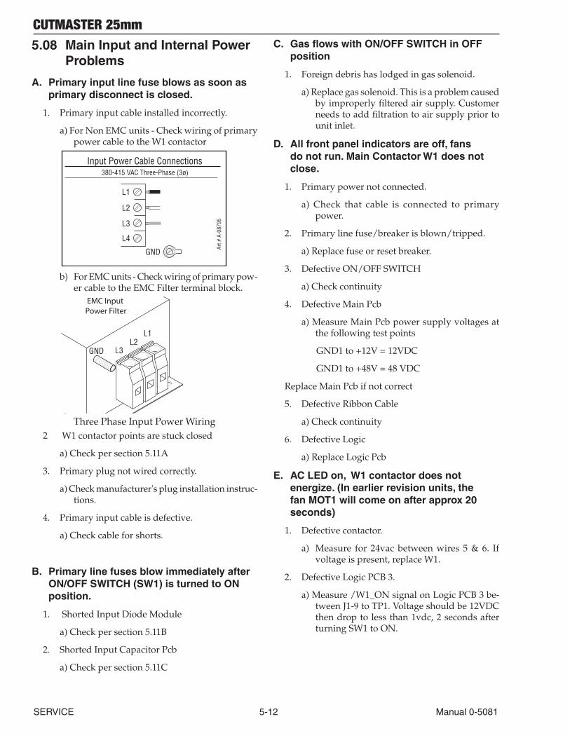
CUTMASTER 25mm
SERVICE 5-12 Manual 0-5081
5.08 Main Input and Internal Power Problems
A. Primary input line fuse blows as soon as primary disconnect is closed.
1. Primary input cable installed incorrectly.
a) For Non EMC units - Check wiring of primary power cable to the W1 contactor
Art #
A-0
8795
Input Power Cable Connections380-415 VAC Three-Phase (3ø)
GND
L1
L2
L3
L4
b) For EMC units - Check wiring of primary pow-er cable to the EMC Filter terminal block.
GND
L1L2
L3
EMC Input Power Filter
Art # A-08752_AAThree Phase Input Power Wiring
2 W1 contactor points are stuck closed
a) Check per section 5.11A
3. Primary plug not wired correctly.
a) Check manufacturer's plug installation instruc-tions.
4. Primary input cable is defective.
a) Check cable for shorts.
B. Primary line fuses blow immediately after ON/OFF SWITCH (SW1) is turned to ON position.
1. Shorted Input Diode Module
a) Check per section 5.11B
2. Shorted Input Capacitor Pcb
a) Check per section 5.11C
C. Gas flows with ON/OFF SWITCH in OFF position
1. Foreign debris has lodged in gas solenoid.
a) Replace gas solenoid. This is a problem caused by improperly filtered air supply. Customer needs to add filtration to air supply prior to unit inlet.
D. All front panel indicators are off, fans do not run. Main Contactor W1 does not close.
1. Primary power not connected.
a) Check that cable is connected to primary power.
2. Primary line fuse/breaker is blown/tripped.
a) Replace fuse or reset breaker.
3. Defective ON/OFF SWITCH
a) Check continuity
4. Defective Main Pcb
a) Measure Main Pcb power supply voltages at the following test points
GND1 to +12V = 12VDC
GND1 to +48V = 48 VDC
Replace Main Pcb if not correct
5. Defective Ribbon Cable
a) Check continuity
6. Defective Logic
a) Replace Logic Pcb
E. AC LED on, W1 contactor does not energize. (In earlier revision units, the fan MOT1 will come on after approx 20 seconds)
1. Defective contactor.
a) Measure for 24vac between wires 5 & 6. If voltage is present, replace W1.
2. Defective Logic PCB 3.
a) Measure /W1_ON signal on Logic PCB 3 be-tween J1-9 to TP1. Voltage should be 12VDC then drop to less than 1vdc, 2 seconds after turning SW1 to ON.
CUTMASTER 25mm
Manual 0-5081 5-13 SERVICE
3. Open or improperly connected ribbon cable to J2 connector on Main PCB 1
a) Inspect connaction and check continuity. Re-place if open.
4) Defective Main PCB 1.
a) Replace Main PCB 1.
F. UNDER PRESSURE FAULT. AC LED on, FAULT Indicator and 60 PSI LED flashing.
1. Air pressure source to unit is too low.
a) Set input pressure source to 90-100PSI.
2. Regulator set too low.
a) Adjust unit regulator to increase pressure.
3. Defective Logic PCB 3
a) Measure for 5VDC on the Logic PCB 3 between J3-3 to J3-1. Replace Logic PCB 3 if voltage is not present or low.
b) Measure for voltage on the Logic PCB 3 be-tween J3-2 to J3-1. If the voltage is between 3-4.5VDC, replace the Logic PCB 3.
4. Defective Pressure Transducer
a) Replace Pressure Transducer
G. INPUT POWER FAULT. AC LED on, FAULT Indicator and 65 PSI LED flashing.
1. Primary line voltage out of tolerance range.
a) Connect unit to voltage with unit specifica-tions. See section "2.04 Power supply speci-fications". If using a generator, connect unit to a wall receptacle to see if problem is cor-rected.
2 Defective Main PCB 1
a) Measure voltage on Main PCB 1 between test point GND1 to J2-22.
400 VAC input = approx 2.6 VDC
If voltage is less than 2vdc, replace Main PCB 1.
3. Defective Ribbon cable.
a) Check continuity of the ribbon cable connect-ing between the Main PCB 1 and the Logic PCB 3.
4. Defective Logic PCB 3.
a) Replace Logic PCB 3.
H. PARTS-IN-PLACE (PIP) FAULT. The FAULT Indicator and 70 PSI LED is flashing. After 20 seconds fan MOT1 turns on.
1. Shield Cup loose
a) Hand tighten the shield cup to close the PIP switch
2. Torch not properly connected to power supply
a) Insure torch ATC is securely fastened to unit.
3. Problem with torch and leads PIP circuit
a) Check continuity of torch PIP circuit at ATC pins 1 & 2.Negative / Plasma Lead
4 Torch Switch
3 Torch Switch
2 PIP
1 PIP
Pilot Lead Art # A-08124
4. Defective Logic Pcb
a) Measure the voltage on Main Pcb between J2-17 to test point GND1 for 12VDC. If the voltage is less than 2VDC, Replace Logic Pcb
5. Defective Main Pcb
a) Replace Main Pcb
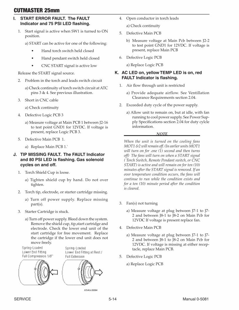
CUTMASTER 25mm
SERVICE 5-14 Manual 0-5081
I. START ERROR FAULT. The FAULT Indicator and 75 PSI LED flashing.
1. Start signal is active when SW1 is turned to ON position.
a) START can be active for one of the following:
• Hand torch switch held closed
• Hand pendant switch held closed
• CNC START signal is active low
Release the START signal source.
2. Problem in the torch and leads switch circuit
a) Check continuity of torch switch circuit at ATC pins 3 & 4. See previous illustration.
3. Short in CNC cable
a) Check continuity
4. Defective Logic PCB 3
a) Measure voltage at Main PCB 1 between J2-16 to test point GND1 for 12VDC. If voltage is present, replace Logic PCB 3.
5. Defective Main PCB 1.
a) Replace Main PCB 1.`
J. TIP MISSING FAULT. The FAULT Indicator and 80 PSI LED is flashing. Gas solenoid cycles on and off.
1. Torch Shield Cup is loose.
a) Tighten shield cup by hand. Do not over tighten.
2. Torch tip, electrode, or starter cartridge missing.
a) Turn off power supply. Replace missing part(s).
3. Starter Cartridge is stuck.
a) Turn off power supply. Bleed down the system. Remove the shield cup, tip,start cartridge and electrode. Check the lower end unit of the start cartridge for free movement. Replace the cartridge if the lower end unit does not move freely.
4. Open conductor in torch leads
a) Check continuity
5. Defective Main PCB
b) Measure voltage at Main Pcb between J2-2 to test point GND1 for 12VDC. If voltage is present, replace Main PCB
6. Defective Logic PCB
a) Replace Logic PCB
K. AC LED on, yellow TEMP LED is on, red FAULT Indicator is flashing.
1. Air flow through unit is restricted
a) Provide adequate airflow. See Ventillation Clearance Requirements section 2.04.
2. Exceeded duty cycle of the power supply.
a) Allow unit to remain on, but at idle, with fan running to cool power supply. See Power Sup-ply Specifications section 2.04 for duty cylcle information.
NOTE
When the unit is turned on the cooling fans MOT1 &2 will remain off. (In earlier units MOT1 will turn on for .one (1) second and then turns off) The fans will turn on when a START signal ( Torch Switch, Remote Pendant switch, or CNC START) is active and will remain on for ten (10) minutes after the START signal is removed. If an over temperature condition occurs, the fans will continue to run while the condition exists and for a ten (10) minute period after the condition is cleared.
3. Fan(s) not turning
a) Measure voltage at plug between J7-1 to J7-2 and between J8-1 to J8-2 on Main Pcb for 12VDC If voltage is present replace fan.
4. Defective Main PCB
a) Measure voltage at plug between J7-1 to J7-2 and between J8-1 to J8-2 on Main Pcb for 12VDC. If voltage is missing at either recep-tacle, replace Main PCB.
5. Defective Logic PCB
a) Replace Logic PCB
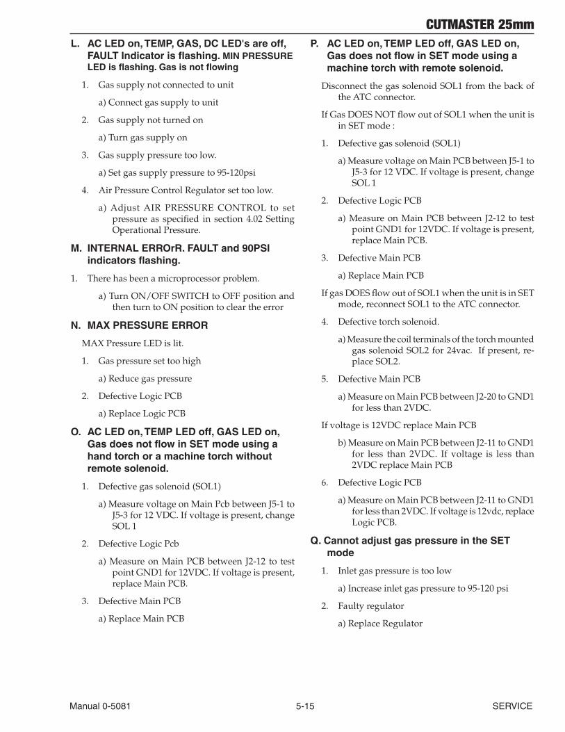
CUTMASTER 25mm
Manual 0-5081 5-15 SERVICE
L. AC LED on, TEMP, GAS, DC LED's are off, FAULT Indicator is flashing. MIN PRESSURE LED is flashing. Gas is not flowing
1. Gas supply not connected to unit
a) Connect gas supply to unit
2. Gas supply not turned on
a) Turn gas supply on
3. Gas supply pressure too low.
a) Set gas supply pressure to 95-120psi
4. Air Pressure Control Regulator set too low.
a) Adjust AIR PRESSURE CONTROL to set pressure as specified in section 4.02 Setting Operational Pressure.
M. INTERNAL ERROrR. FAULT and 90PSI indicators flashing.
1. There has been a microprocessor problem.
a) Turn ON/OFF SWITCH to OFF position and then turn to ON position to clear the error
N. MAX PRESSURE ERROR
MAX Pressure LED is lit.
1. Gas pressure set too high
a) Reduce gas pressure
2. Defective Logic PCB
a) Replace Logic PCB
O. AC LED on, TEMP LED off, GAS LED on, Gas does not flow in SET mode using a hand torch or a machine torch without remote solenoid.
1. Defective gas solenoid (SOL1)
a) Measure voltage on Main Pcb between J5-1 to J5-3 for 12 VDC. If voltage is present, change SOL 1
2. Defective Logic Pcb
a) Measure on Main PCB between J2-12 to test point GND1 for 12VDC. If voltage is present, replace Main PCB.
3. Defective Main PCB
a) Replace Main PCB
P. AC LED on, TEMP LED off, GAS LED on, Gas does not flow in SET mode using a machine torch with remote solenoid.
Disconnect the gas solenoid SOL1 from the back of the ATC connector.
If Gas DOES NOT flow out of SOL1 when the unit is in SET mode :
1. Defective gas solenoid (SOL1)
a) Measure voltage on Main PCB between J5-1 to J5-3 for 12 VDC. If voltage is present, change SOL 1
2. Defective Logic PCB
a) Measure on Main PCB between J2-12 to test point GND1 for 12VDC. If voltage is present, replace Main PCB.
3. Defective Main PCB
a) Replace Main PCB
If gas DOES flow out of SOL1 when the unit is in SET mode, reconnect SOL1 to the ATC connector.
4. Defective torch solenoid.
a) Measure the coil terminals of the torch mounted gas solenoid SOL2 for 24vac. If present, re-place SOL2.
5. Defective Main PCB
a) Measure on Main PCB between J2-20 to GND1 for less than 2VDC.
If voltage is 12VDC replace Main PCB
b) Measure on Main PCB between J2-11 to GND1 for less than 2VDC. If voltage is less than 2VDC replace Main PCB
6. Defective Logic PCB
a) Measure on Main PCB between J2-11 to GND1 for less than 2VDC. If voltage is 12vdc, replace Logic PCB.
Q. Cannot adjust gas pressure in the SET mode
1. Inlet gas pressure is too low
a) Increase inlet gas pressure to 95-120 psi
2. Faulty regulator
a) Replace Regulator
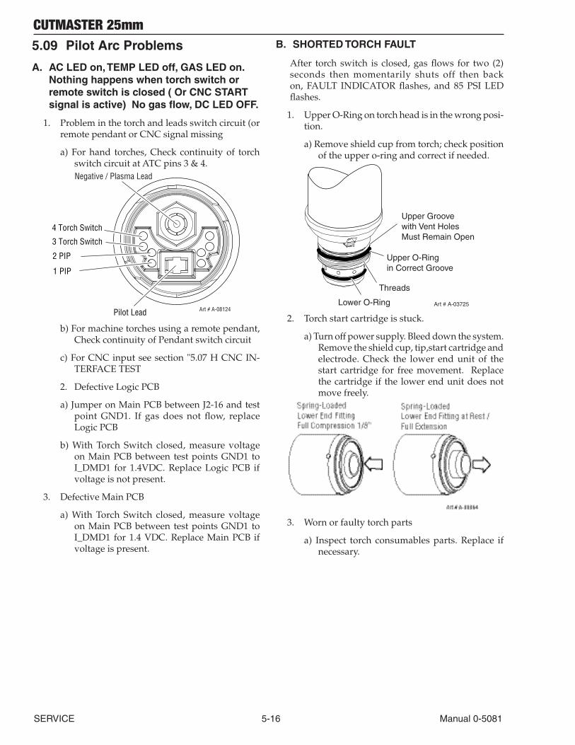
CUTMASTER 25mm
SERVICE 5-16 Manual 0-5081
5.09 Pilot Arc Problems
A. AC LED on, TEMP LED off, GAS LED on. Nothing happens when torch switch or remote switch is closed ( Or CNC START signal is active) No gas flow, DC LED OFF.
1. Problem in the torch and leads switch circuit (or remote pendant or CNC signal missing
a) For hand torches, Check continuity of torch switch circuit at ATC pins 3 & 4. Negative / Plasma Lead
4 Torch Switch
3 Torch Switch
2 PIP
1 PIP
Pilot Lead Art # A-08124
b) For machine torches using a remote pendant, Check continuity of Pendant switch circuit
c) For CNC input see section "5.07 H CNC IN-TERFACE TEST
2. Defective Logic PCB
a) Jumper on Main PCB between J2-16 and test point GND1. If gas does not flow, replace Logic PCB
b) With Torch Switch closed, measure voltage on Main PCB between test points GND1 to I_DMD1 for 1.4VDC. Replace Logic PCB if voltage is not present.
3. Defective Main PCB
a) With Torch Switch closed, measure voltage on Main PCB between test points GND1 to I_DMD1 for 1.4 VDC. Replace Main PCB if voltage is present.
B. SHORTED TORCH FAULT
After torch switch is closed, gas flows for two (2) seconds then momentarily shuts off then back on, FAULT INDICATOR flashes, and 85 PSI LED flashes.
1. Upper O-Ring on torch head is in the wrong posi-tion.
a) Remove shield cup from torch; check position of the upper o-ring and correct if needed.
Upper Groovewith Vent HolesMust Remain Open
Threads
Upper O-Ringin Correct Groove
Lower O-Ring Art # A-03725
2. Torch start cartridge is stuck.
a) Turn off power supply. Bleed down the system. Remove the shield cup, tip,start cartridge and electrode. Check the lower end unit of the start cartridge for free movement. Replace the cartridge if the lower end unit does not move freely.
3. Worn or faulty torch parts
a) Inspect torch consumables parts. Replace if necessary.
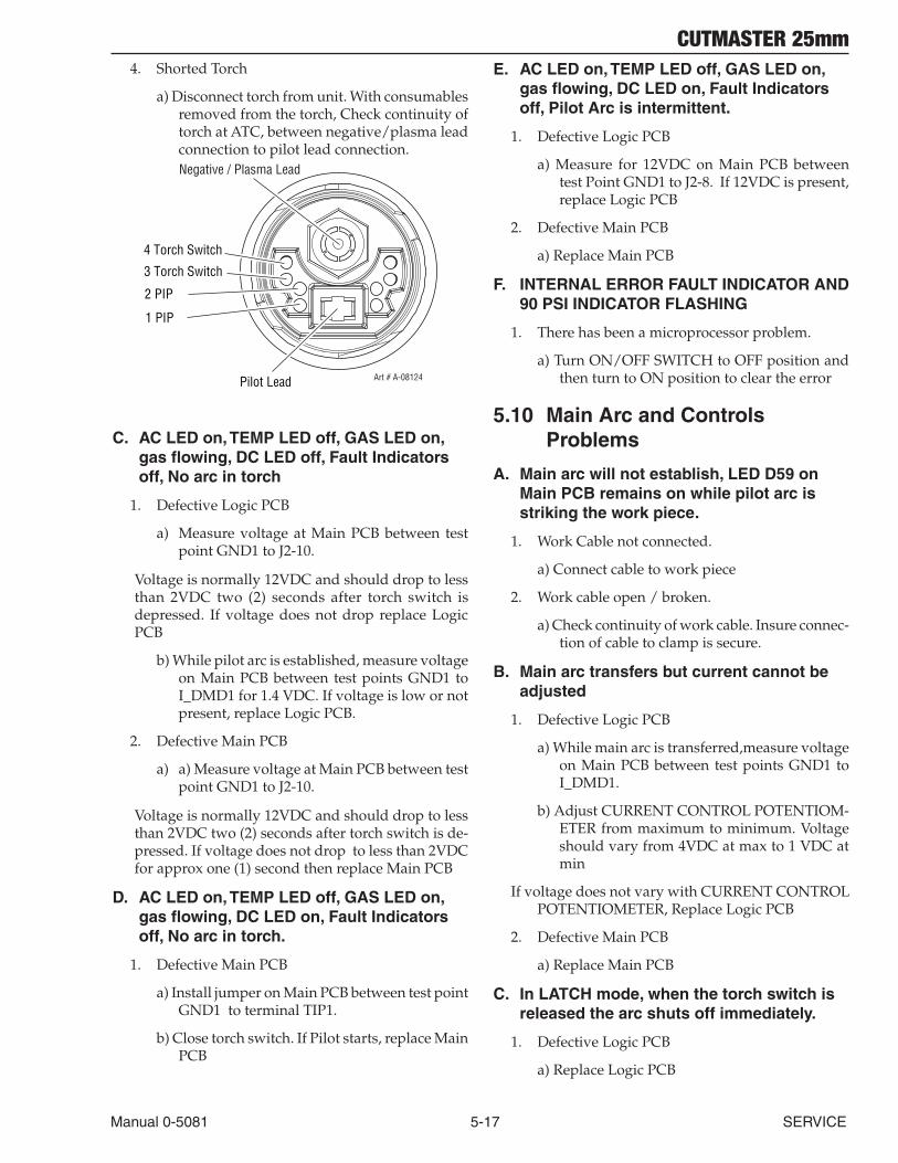
CUTMASTER 25mm
Manual 0-5081 5-17 SERVICE
4. Shorted Torch
a) Disconnect torch from unit. With consumables removed from the torch, Check continuity of torch at ATC, between negative/plasma lead connection to pilot lead connection. Negative / Plasma Lead
4 Torch Switch
3 Torch Switch
2 PIP
1 PIP
Pilot Lead Art # A-08124
C. AC LED on, TEMP LED off, GAS LED on, gas flowing, DC LED off, Fault Indicators off, No arc in torch
1. Defective Logic PCB
a) Measure voltage at Main PCB between test point GND1 to J2-10.
Voltage is normally 12VDC and should drop to less than 2VDC two (2) seconds after torch switch is depressed. If voltage does not drop replace Logic PCB
b) While pilot arc is established, measure voltage on Main PCB between test points GND1 to I_DMD1 for 1.4 VDC. If voltage is low or not present, replace Logic PCB.
2. Defective Main PCB
a) a) Measure voltage at Main PCB between test point GND1 to J2-10.
Voltage is normally 12VDC and should drop to less than 2VDC two (2) seconds after torch switch is de-pressed. If voltage does not drop to less than 2VDC for approx one (1) second then replace Main PCB
D. AC LED on, TEMP LED off, GAS LED on, gas flowing, DC LED on, Fault Indicators off, No arc in torch.
1. Defective Main PCB
a) Install jumper on Main PCB between test point GND1 to terminal TIP1.
b) Close torch switch. If Pilot starts, replace Main PCB
E. AC LED on, TEMP LED off, GAS LED on, gas flowing, DC LED on, Fault Indicators off, Pilot Arc is intermittent.
1. Defective Logic PCB
a) Measure for 12VDC on Main PCB between test Point GND1 to J2-8. If 12VDC is present, replace Logic PCB
2. Defective Main PCB
a) Replace Main PCB
F. INTERNAL ERROR FAULT INDICATOR AND 90 PSI INDICATOR FLASHING
1. There has been a microprocessor problem.
a) Turn ON/OFF SWITCH to OFF position and then turn to ON position to clear the error
5.10 Main Arc and Controls Problems
A. Main arc will not establish, LED D59 on Main PCB remains on while pilot arc is striking the work piece.
1. Work Cable not connected.
a) Connect cable to work piece
2. Work cable open / broken.
a) Check continuity of work cable. Insure connec-tion of cable to clamp is secure.
B. Main arc transfers but current cannot be adjusted
1. Defective Logic PCB
a) While main arc is transferred,measure voltage on Main PCB between test points GND1 to I_DMD1.
b) Adjust CURRENT CONTROL POTENTIOM-ETER from maximum to minimum. Voltage should vary from 4VDC at max to 1 VDC at min
If voltage does not vary with CURRENT CONTROL POTENTIOMETER, Replace Logic PCB
2. Defective Main PCB
a) Replace Main PCB
C. In LATCH mode, when the torch switch is released the arc shuts off immediately.
1. Defective Logic PCB
a) Replace Logic PCB

CUTMASTER 25mm
SERVICE 5-18 Manual 0-5081
D. With CURRENT CONTROL POTENTIOMETER set at maximum, output current is only 60 amps.
1. Tip is touching the work piece, Drag mode.
a) Lift tip off work piece
2. Defective Pilot IGBT on Main PCB
a) Check per section 4.10.
E. In RAPID AUTO RESTART mode, with torch switch closed, the pilot does not start immediately when the cutting arc extinguishes
1. Defective Logic PCB
a) Replace Logic PCB
F. INTERNAL ERROR FAULT INDICATOR AND 90 PSI INDICATOR FLASHING
1. There has been a microprocessor problem.
a) Turn ON/OFF SWITCH to OFF position and then turn to ON position to clear the error
5.11 CNC Interface Problems
A. Nothing happens when jumper is installed between J2-3 to J2-4.
1. Defective Automation Interface PCB (PCB4)
a) Measure voltage on PCB4 between J1-6 to J1-8 for 12VDC.
If 12VDC is present replace PCB4
2. Defective Main PCB
a) Measure voltage on Main PCB between J1-6 to J1-8 for less than 2VDC.
If voltage is less than 2VDC, replace PCB1
B. No OK-TO-MOVE signal while cutting.
1. Defective Main Pcb (PCB1)
a) Measure voltage on PCB4 between J1-1 to J1-3 for 12VDC while cutting.
If 12VDC is present, replace PCB1
2. Defective Automation Interface PCB (PCB4)
a) Measure voltage on PCB4 between J1-1 to J1-3 for less than 2VDC while cutting.
If voltage is less than 2VDC, replace PCB4.
C. ARC VOLTS signals are low or not present
1. Defective Automation Interface PCB (PCB4)
a) Replace PCB4
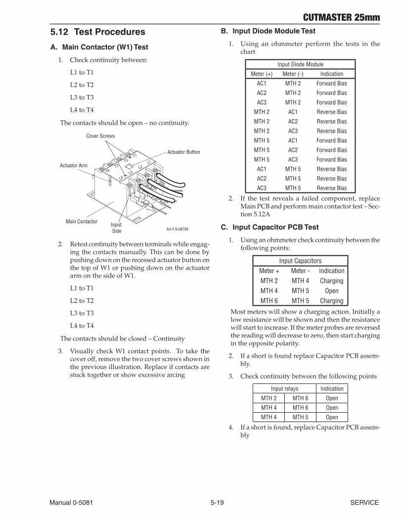
CUTMASTER 25mm
Manual 0-5081 5-19 SERVICE
5.12 Test Procedures
A. Main Contactor (W1) Test
1. Check continuity between:
L1 to T1
L2 to T2
L3 to T3
L4 to T4
The contacts should be open – no continuity.
L4 L3
L2 L1
T4 T3
T2 T1
Actuator Arm
Cover Screws
Art # A-08794Input Side
Main Contactor
Actuator Button
2. Retest continuity between terminals while engag-ing the contacts manually. This can be done by pushing down on the recessed actuator button on the top of W1 or pushing down on the actuator arm on the side of W1.
L1 to T1
L2 to T2
L3 to T3
L4 to T4
The contacts should be closed – Continuity
3. Visually check W1 contact points. To take the cover off, remove the two cover screws shown in the previous illustration. Replace if contacts are stuck together or show excessive arcing
B. Input Diode Module Test
1. Using an ohmmeter perform the tests in the chart
Input Diode Module
Meter (+) Meter (-) Indication
AC1 MTH 2 Forward Bias
AC2 MTH 2 Forward Bias
AC3 MTH 2 Forward Bias
MTH 2 AC1 Reverse Bias
MTH 2 AC2 Reverse Bias
MTH 2 AC3 Reverse Bias
MTH 5 AC1 Forward Bias
MTH 5 AC2 Forward Bias
MTH 5 AC3 Forward Bias
AC1 MTH 5 Reverse Bias
AC2 MTH 5 Reverse Bias
AC3 MTH 5 Reverse Bias
2. If the test reveals a failed component, replace Main PCB and perform main contactor test – Sec-tion 5.12A
C. Input Capacitor PCB Test
1. Using an ohmmeter check continuity between the following points:
Input CapacitorsMeter + Meter - IndicationMTH 2 MTH 4 ChargingMTH 4 MTH 5 OpenMTH 6 MTH 5 Charging
Most meters will show a charging action. Initially a low resistance will be shown and then the resistance will start to increase. If the meter probes are reversed the reading will decrease to zero, then start charging in the opposite polarity.
2. If a short is found replace Capacitor PCB assem-bly.
3. Check continuity between the following points
Input relays Indication
MTH 2 MTH 6 Open
MTH 4 MTH 6 Open
MTH 4 MTH 5 Open
4. If a short is found, replace Capacitor PCB assem-bly
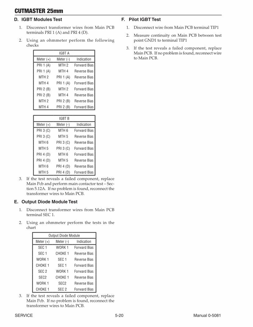
CUTMASTER 25mm
SERVICE 5-20 Manual 0-5081
D. IGBT Modules Test
1. Disconnect transformer wires from Main PCB terminals PRI 1 (A) and PRI 4 (D).
2. Using an ohmmeter perform the following checks
IGBT A
Meter (+) Meter (-) Indication
PRI 1 (A) MTH 2 Forward Bias
PRI 1 (A) MTH 4 Reverse Bias
MTH 2 PRI 1 (A) Reverse Bias
MTH 4 PRI 1 (A) Forward Bias
PRI 2 (B) MTH 2 Forward Bias
PRI 2 (B) MTH 4 Reverse Bias
MTH 2 PRI 2 (B) Reverse Bias
MTH 4 PRI 2 (B) Forward Bias
IGBT B
Meter (+) Meter (-) Indication
PRI 3 (C) MTH 6 Forward Bias
PRI 3 (C) MTH 5 Reverse Bias
MTH 6 PRI 3 (C) Reverse Bias
MTH 5 PRI 3 (C) Forward Bias
PRI 4 (D) MTH 6 Forward Bias
PRI 4 (D) MTH 5 Reverse Bias
MTH 6 PRI 4 (D) Reverse Bias
MTH 5 PRI 4 (D) Forward Bias
3. If the test reveals a failed component, replace Main Pcb and perform main contactor test – Sec-tion 5.12A. If no problem is found, reconnect the transformer wires to Main PCB.
E. Output Diode Module Test
1. Disconnect transformer wires from Main PCB terminal SEC 1.
2. Using an ohmmeter perform the tests in the chart
Output Diode Module
Meter (+) Meter (-) Indication
SEC 1 WORK 1 Forward Bias
SEC 1 CHOKE 1 Reverse Bias
WORK 1 SEC 1 Reverse Bias
CHOKE 1 SEC 1 Forward Bias
SEC 2 WORK 1 Forward Bias
SEC2 CHOKE 1 Reverse Bias
WORK 1 SEC2 Reverse Bias
CHOKE 1 SEC 2 Forward Bias
3. If the test reveals a failed component, replace Main Pcb. If no problem is found, reconnect the transformer wires to Main PCB.
F. Pilot IGBT Test
1. Disconnect wire from Main PCB terminal TIP1
2. Measure continuity on Main PCB between test point GND1 to terminal TIP1
3. If the test reveals a failed component, replace Main PCB. If no problem is found, reconnect wire to Main PCB.

CUTMASTER 25mm
Manual 0-5081 5-21 SERVICE
Signal Information
Many of the signal listed will be low voltage signals that will be in one of two states: +12VDC (High) or 0VDC (Low) with respect to pcb common.. When a signal name is preceded by the “/” mark, it denotes that the signal is an active low. For example:
/OVERTEMP – This signal is normally High but when an over temperature fault exists, this line will change state to a Low.
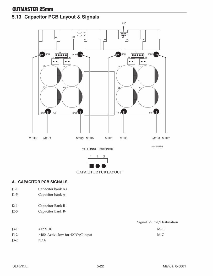
CUTMASTER 25mm
SERVICE 5-22 Manual 0-5081
5.13 Capacitor PCB Layout & Signals
MTH8 MTH7 MTH5 MTH6 MTH1 MTH3 MTH4 MTH2
J3*
*J3 CONNECTOR PINOUT
1 2 3
Art # A-08841
CAPACITOR PCB LAYOUT
A. CAPACITOR PCB SIGNALS
J1-1 Capacitor bank A+
J1-5 Capacitor bank A-
J2-1 Capacitor Bank B+
J2-5 Capacitor Bank B-
Signal Source/Destination
J3-1 +12 VDC M-C
J3-2 /400 Active low for 400VAC input M-C
J3-2 N/A

CUTMASTER 25mm
Manual 0-5081 5-23 SERVICE
B. CAPACITOR PCB TEST POINTS
MTH1,2 Capacitor bank A+
MTH3,4 Capacitor bank A-
MTH6,8 Capacitor Bank B+
MTH 5,7 Capacitor Bank B-
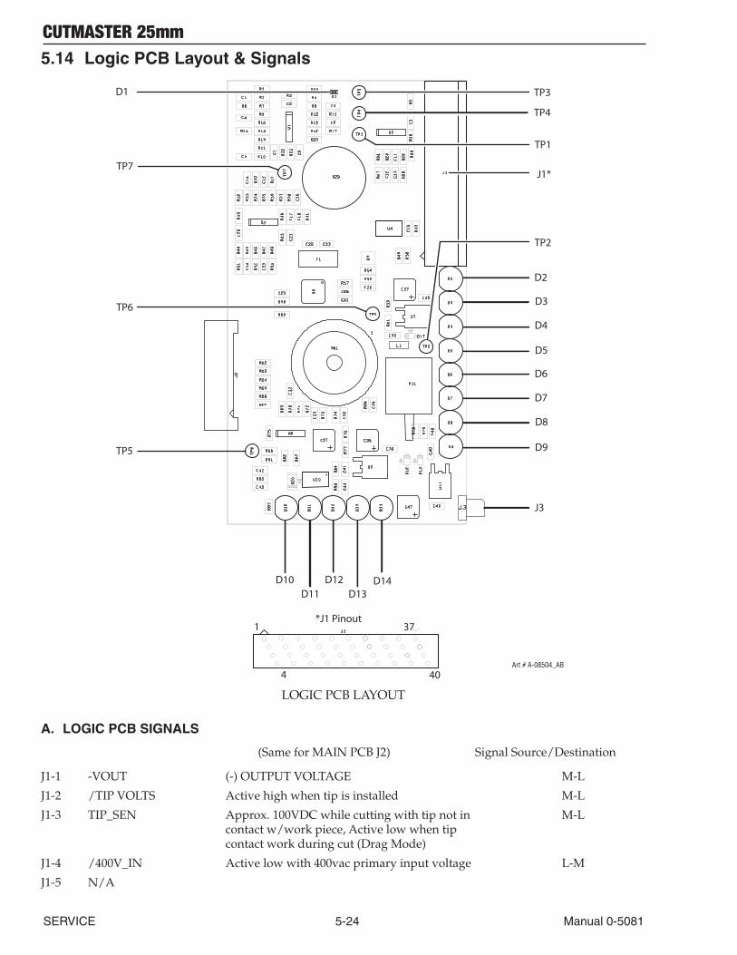
CUTMASTER 25mm
SERVICE 5-24 Manual 0-5081
5.14 Logic PCB Layout & Signals
D5
D3
D2
D4
D6
D7
D8
D9
TP4
TP1
J1*
TP2
TP7
TP6
TP5
D10D11
D12D13
D14
1
4
37
40
*J1 Pinout
Art # A-08504_AB
D1 TP3
J3
LOGIC PCB LAYOUT
A. LOGIC PCB SIGNALS
(Same for MAIN PCB J2) Signal Source/Destination
J1-1 -VOUT (-) OUTPUT VOLTAGE M-L
J1-2 /TIP VOLTS Active high when tip is installed M-L
J1-3 TIP_SEN Approx. 100VDC while cutting with tip not in M-L contact w/work piece, Active low when tip contact work during cut (Drag Mode)
J1-4 /400V_IN Active low with 400vac primary input voltage L-M
J1-5 N/A
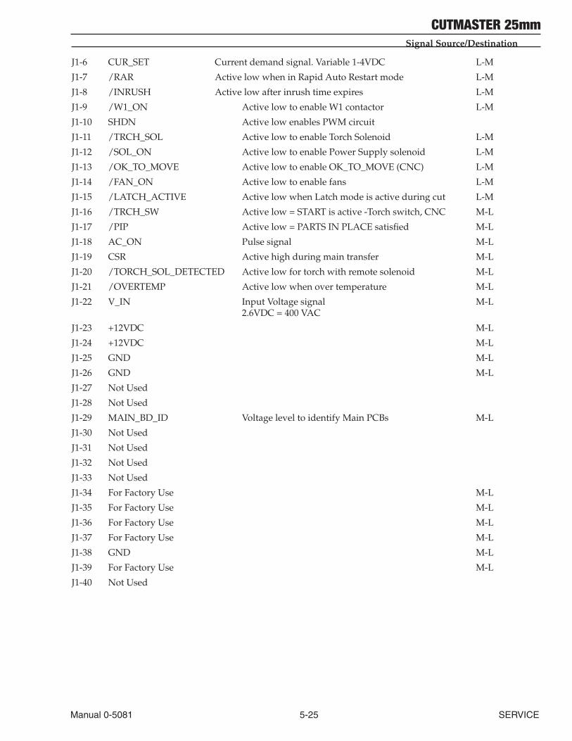
CUTMASTER 25mm
Manual 0-5081 5-25 SERVICE
Signal Source/Destination
J1-6 CUR_SET Current demand signal. Variable 1-4VDC L-M
J1-7 /RAR Active low when in Rapid Auto Restart mode L-M
J1-8 /INRUSH Active low after inrush time expires L-M
J1-9 /W1_ON Active low to enable W1 contactor L-M
J1-10 SHDN Active low enables PWM circuit
J1-11 /TRCH_SOL Active low to enable Torch Solenoid L-M
J1-12 /SOL_ON Active low to enable Power Supply solenoid L-M
J1-13 /OK_TO_MOVE Active low to enable OK_TO_MOVE (CNC) L-M
J1-14 /FAN_ON Active low to enable fans L-M
J1-15 /LATCH_ACTIVE Active low when Latch mode is active during cut L-M
J1-16 /TRCH_SW Active low = START is active -Torch switch, CNC M-L
J1-17 /PIP Active low = PARTS IN PLACE satisfied M-L
J1-18 AC_ON Pulse signal M-L
J1-19 CSR Active high during main transfer M-L
J1-20 /TORCH_SOL_DETECTED Active low for torch with remote solenoid M-L
J1-21 /OVERTEMP Active low when over temperature M-L
J1-22 V_IN Input Voltage signal M-L 2.6VDC = 400 VAC
J1-23 +12VDC M-L
J1-24 +12VDC M-L
J1-25 GND M-L
J1-26 GND M-L
J1-27 Not Used
J1-28 Not Used
J1-29 MAIN_BD_ID Voltage level to identify Main PCBs M-L
J1-30 Not Used
J1-31 Not Used
J1-32 Not Used
J1-33 Not Used
J1-34 For Factory Use M-L
J1-35 For Factory Use M-L
J1-36 For Factory Use M-L
J1-37 For Factory Use M-L
J1-38 GND M-L
J1-39 For Factory Use M-L
J1-40 Not Used
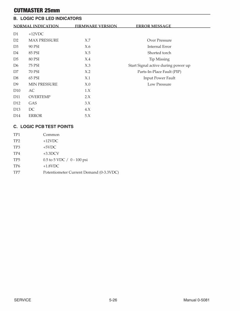
CUTMASTER 25mm
SERVICE 5-26 Manual 0-5081
B. LOGIC PCB LED INDICATORS
NORMAL INDICATION FIRMWARE VERSION ERROR MESSAGE
D1 +12VDC
D2 MAX PRESSURE X.7 Over Pressure
D3 90 PSI X.6 Internal Error
D4 85 PSI X.5 Shorted torch
D5 80 PSI X.4 Tip Missing
D6 75 PSI X.3 Start Signal active during power up
D7 70 PSI X.2 Parts-In-Place Fault (PIP)
D8 65 PSI X.1 Input Power Fault
D9 MIN PRESSURE X.0 Low Pressure
D10 AC 1.X
D11 OVERTEMP 2.X
D12 GAS 3.X
D13 DC 4.X
D14 ERROR 5.X
C. LOGIC PCB TEST POINTS
TP1 Common
TP2 +12VDC
TP3 +5VDC
TP4 +3.3DCV
TP5 0.5 to 5 VDC / 0 - 100 psi
TP6 +1.8VDC
TP7 Potentiometer Current Demand (0-3.3VDC)

CUTMASTER 25mm
Manual 0-5081 5-27 SERVICE
This Page Intentionally Blank
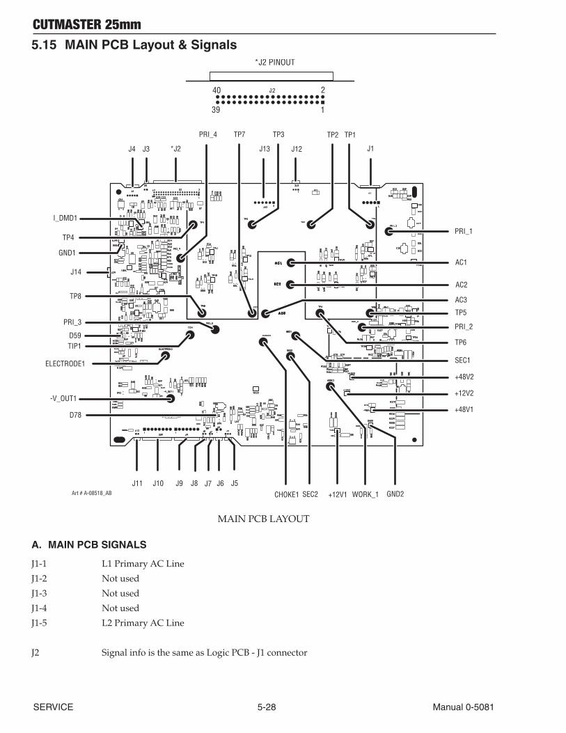
CUTMASTER 25mm
SERVICE 5-28 Manual 0-5081
5.15 MAIN PCB Layout & Signals
J10 J9 J8 J7 J6 J5
D78
J14
D59
GND2
+48V1
CHOKE1 SEC2
SEC1
TIP1
PRI_3
ELECTRODE1
-V_OUT1
J4 J3 *J2
TP8
TP7
J13 J12
TP2 TP1
J1
TP3
I_DMD1
GND1
+12V1
+12V2
+48V2
TP6
PRI_2
TP5
AC3
AC1
AC2
WORK_1
PRI_1
PRI_4
TP4
J11Art # A-08518_AB
139
40 2
*J2 PINOUT
MAIN PCB LAYOUT
A. MAIN PCB SIGNALS
J1-1 L1 Primary AC Line
J1-2 Not used
J1-3 Not used
J1-4 Not used
J1-5 L2 Primary AC Line
J2 Signal info is the same as Logic PCB - J1 connector
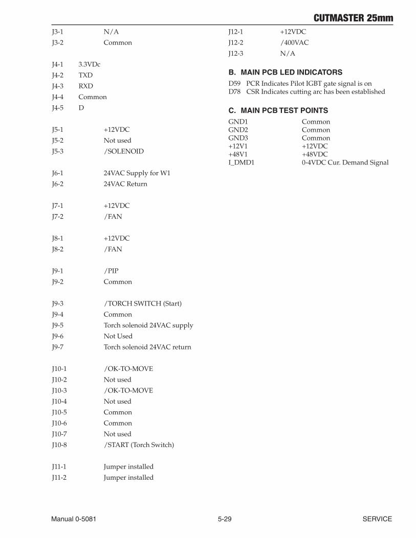
CUTMASTER 25mm
Manual 0-5081 5-29 SERVICE
J3-1 N/A
J3-2 Common
J4-1 3.3VDc
J4-2 TXD
J4-3 RXD
J4-4 Common
J4-5 D
J5-1 +12VDC
J5-2 Not used
J5-3 /SOLENOID
J6-1 24VAC Supply for W1
J6-2 24VAC Return
J7-1 +12VDC
J7-2 /FAN
J8-1 +12VDC
J8-2 /FAN
J9-1 /PIP
J9-2 Common
J9-3 /TORCH SWITCH (Start)
J9-4 Common
J9-5 Torch solenoid 24VAC supply
J9-6 Not Used
J9-7 Torch solenoid 24VAC return
J10-1 /OK-TO-MOVE
J10-2 Not used
J10-3 /OK-TO-MOVE
J10-4 Not used
J10-5 Common
J10-6 Common
J10-7 Not used
J10-8 /START (Torch Switch)
J11-1 Jumper installed
J11-2 Jumper installed
J12-1 +12VDC
J12-2 /400VAC
J12-3 N/A
B. MAIN PCB LED INDICATORS D59 PCR Indicates Pilot IGBT gate signal is onD78 CSR Indicates cutting arc has been established
C. MAIN PCB TEST POINTSGND1 CommonGND2 CommonGND3 Common+12V1 +12VDC+48V1 +48VDCI_DMD1 0-4VDC Cur. Demand Signal
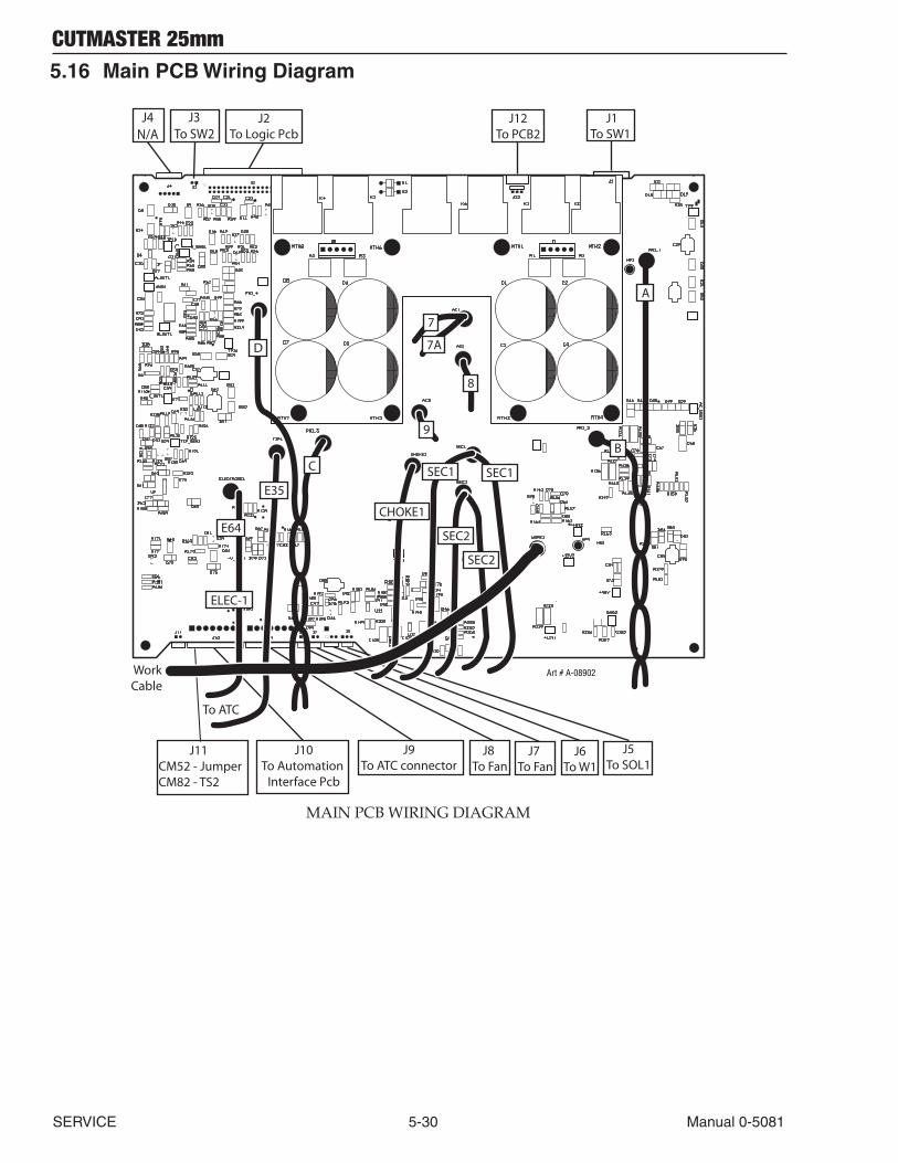
CUTMASTER 25mm
SERVICE 5-30 Manual 0-5081
5.16 Main PCB Wiring Diagram
To ATC
Work Cable
J2To Logic Pcb
J12To PCB2
J1To SW1
J10To Automation
Interface Pcb
J9To ATC connector
J8 To Fan
J5To SOL1
J6To W1
J3To SW2
J11CM52 - JumperCM82 - TS2
J7 To Fan
SEC2
SEC2
SEC1SEC1
7
7A
8
9
ELEC-1
CHOKE1
J4N/A
E64
A
B
E35
D
C
Art # A-08902
MAIN PCB WIRING DIAGRAM
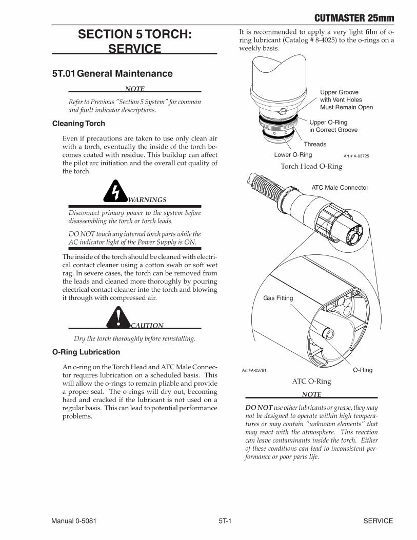
CUTMASTER 25mm
Manual 0-5081 5T-1 SERVICE
SECTION 5 TORCH: SERVICE
5T.01 General Maintenance
NOTE
Refer to Previous "Section 5 System" for common and fault indicator descriptions.
Cleaning Torch
Even if precautions are taken to use only clean air with a torch, eventually the inside of the torch be-comes coated with residue. This buildup can affect the pilot arc initiation and the overall cut quality of the torch.
WARNINGS
Disconnect primary power to the system before disassembling the torch or torch leads.
DO NOT touch any internal torch parts while the AC indicator light of the Power Supply is ON.
The inside of the torch should be cleaned with electri-cal contact cleaner using a cotton swab or soft wet rag. In severe cases, the torch can be removed from the leads and cleaned more thoroughly by pouring electrical contact cleaner into the torch and blowing it through with compressed air.
CAUTION
Dry the torch thoroughly before reinstalling.
O-Ring Lubrication
An o-ring on the Torch Head and ATC Male Connec-tor requires lubrication on a scheduled basis. This will allow the o-rings to remain pliable and provide a proper seal. The o-rings will dry out, becoming hard and cracked if the lubricant is not used on a regular basis. This can lead to potential performance problems.
It is recommended to apply a very light film of o-ring lubricant (Catalog # 8-4025) to the o-rings on a weekly basis.
Upper Groovewith Vent HolesMust Remain Open
Threads
Upper O-Ringin Correct Groove
Lower O-Ring Art # A-03725
Torch Head O-Ring
ATC Male Connector
Art #A-03791
Gas Fitting
O-Ring
ATC O-Ring
NOTE
DO NOT use other lubricants or grease, they may not be designed to operate within high tempera-tures or may contain “unknown elements” that may react with the atmosphere. This reaction can leave contaminants inside the torch. Either of these conditions can lead to inconsistent per-formance or poor parts life.
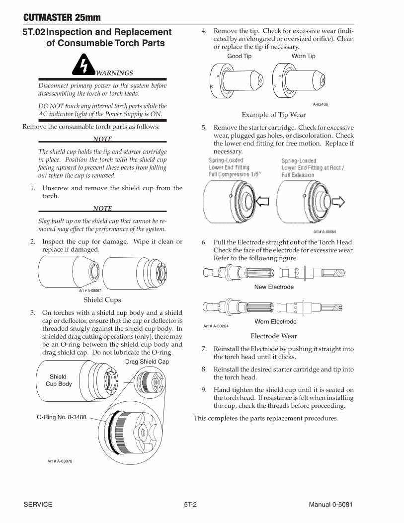
CUTMASTER 25mm
SERVICE 5T-2 Manual 0-5081
5T.02 Inspection and Replacement of Consumable Torch Parts
WARNINGS
Disconnect primary power to the system before disassembling the torch or torch leads.
DO NOT touch any internal torch parts while the AC indicator light of the Power Supply is ON.
Remove the consumable torch parts as follows:
NOTE
The shield cup holds the tip and starter cartridge in place. Position the torch with the shield cup facing upward to prevent these parts from falling out when the cup is removed.
1. Unscrew and remove the shield cup from the torch.
NOTE
Slag built up on the shield cup that cannot be re-moved may effect the performance of the system.
2. Inspect the cup for damage. Wipe it clean or replace if damaged.
Art # A-08067
Shield Cups
3. On torches with a shield cup body and a shield cap or deflector, ensure that the cap or deflector is threaded snugly against the shield cup body. In shielded drag cutting operations (only), there may be an O-ring between the shield cup body and drag shield cap. Do not lubricate the O-ring.
Drag Shield Cap
Shield Cup Body
O-Ring No. 8-3488
Art # A-03878
4. Remove the tip. Check for excessive wear (indi-cated by an elongated or oversized orifice). Clean or replace the tip if necessary.
Good Tip Worn Tip
A-03406
Example of Tip Wear
5. Remove the starter cartridge. Check for excessive wear, plugged gas holes, or discoloration. Check the lower end fitting for free motion. Replace if necessary.
6. Pull the Electrode straight out of the Torch Head. Check the face of the electrode for excessive wear. Refer to the following figure.
Worn Electrode
New Electrode
Art # A-03284
Electrode Wear
7. Reinstall the Electrode by pushing it straight into the torch head until it clicks.
8. Reinstall the desired starter cartridge and tip into the torch head.
9. Hand tighten the shield cup until it is seated on the torch head. If resistance is felt when installing the cup, check the threads before proceeding.
This completes the parts replacement procedures.
CUTMASTER 25mm
Manual 0-5081 6-1 PARTS LIST
SECTION 6: PARTS LISTS
6.01 Introduction
A. Parts List Breakdown
The parts list provide a breakdown of all replaceable components. The parts lists are arranged as follows:
Section 6.03 Complete Power Supply Replacement
Section 6.04 Major External Replacement Parts
Section 6.05 Front Panel Replacement parts
Section 6.06 Left Side Replacement Parts
Section 6.07 Right Side Replacement Parts
Section 6.08 Options and Accessories
Section 6.09 Replacement Parts for Hand Torch
Section 6.10 Replacement Parts - for Mechanized Torches with Unshielded Leads
Section 6.11 Torch Consumable Parts Manual and Mechanized TorchesNOTE
Parts listed without item numbers are not shown, but may be ordered by the catalog number shown.
B. Returns
If a product must be returned for service, contact your distributor. Materials returned without proper authoriza-tion will not be accepted.
6.02 Ordering Information
Order replacement parts by catalog number and complete description of the part or assembly, as listed in the parts list for each type item. Also include the model and serial number of the power supply. Address all inquiries to your authorized distributor.
6.03 Power Supply Replacement
The following items are included with the replacement power supply: work cable & clamp, input power cable, gas pressure regulator / filter, and operating manual.
Qty Description Catalog #
1 CutMaster 25mm Non CE Power Supply with 380/400/415VAC, 3 Phase, 50/60 Hz, with input power cable 3-1330-3
1 CutMaster 25mm CE Power Supply with 380/400/415VAC, 3 Phase, 50/60 Hz, with input power cable 3-1330-4
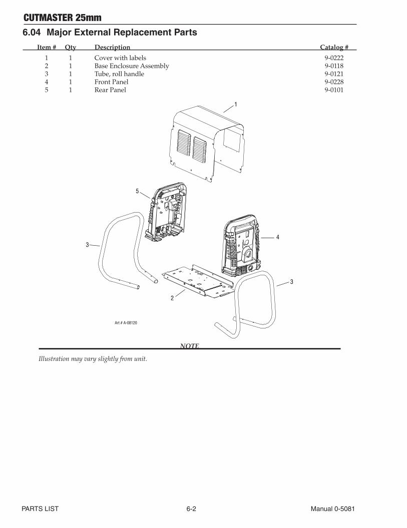
CUTMASTER 25mm
PARTS LIST 6-2 Manual 0-5081
6.04 Major External Replacement Parts
Item # Qty Description Catalog #
1 1 Cover with labels 9-0222 2 1 Base Enclosure Assembly 9-0118 3 1 Tube, roll handle 9-0121 4 1 Front Panel 9-0228 5 1 Rear Panel 9-0101
Art # A-08120
3
2
4
5
1
3
NOTE
Illustration may vary slightly from unit.
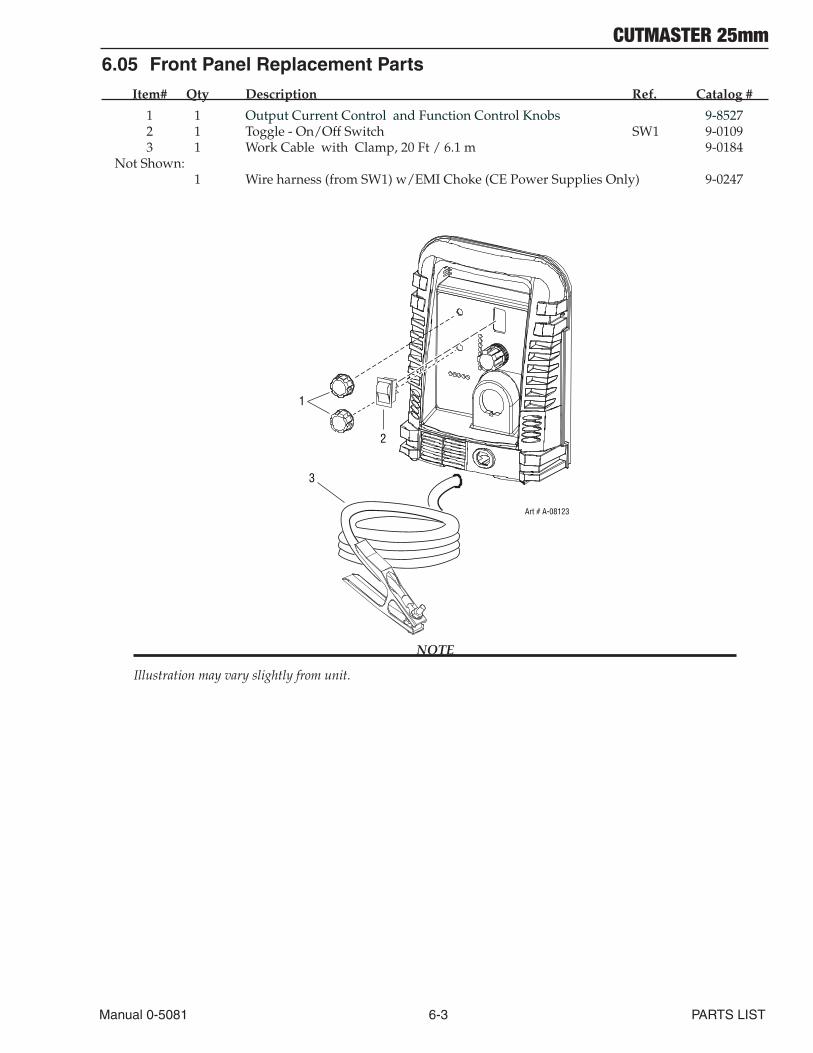
CUTMASTER 25mm
Manual 0-5081 6-3 PARTS LIST
6.05 Front Panel Replacement Parts
Item# Qty Description Ref. Catalog #
1 1 Output Current Control and Function Control Knobs 9-8527 2 1 Toggle - On/Off Switch SW1 9-0109 3 1 Work Cable with Clamp, 20 Ft / 6.1 m 9-0184 Not Shown: 1 Wire harness (from SW1) w/EMI Choke (CE Power Supplies Only) 9-0247
Art # A-08123
1
2
3
NOTE
Illustration may vary slightly from unit.
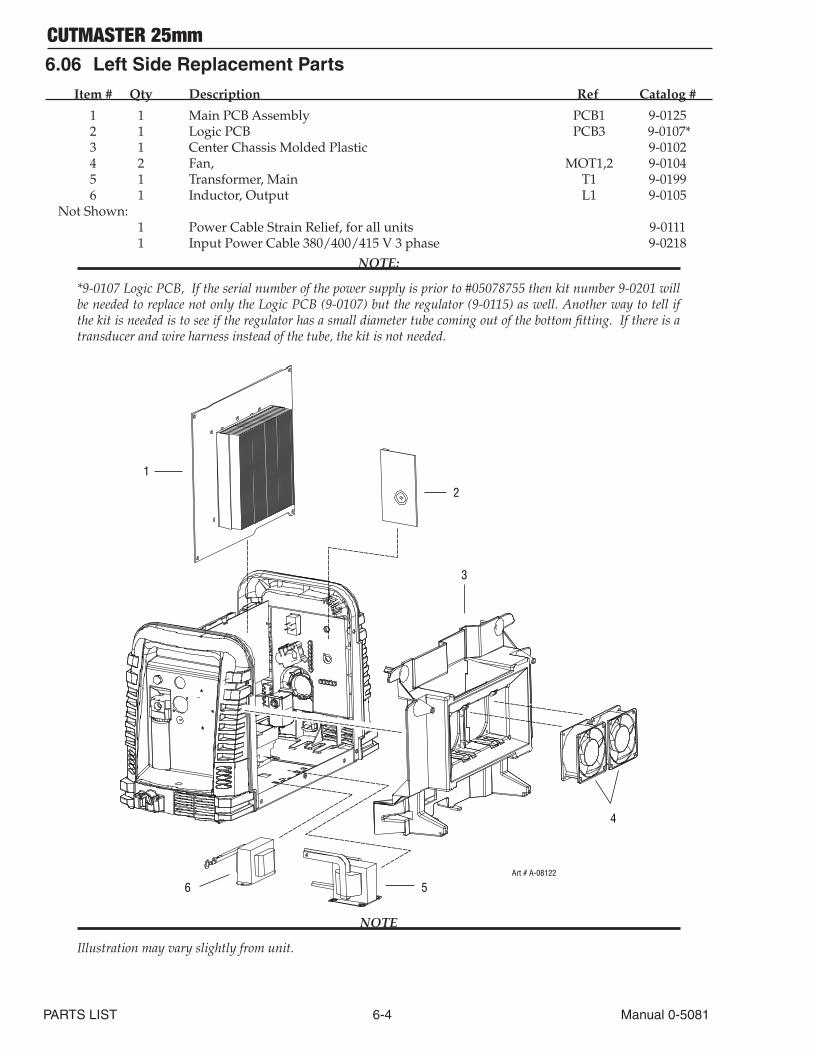
CUTMASTER 25mm
PARTS LIST 6-4 Manual 0-5081
6.06 Left Side Replacement Parts
Item # Qty Description Ref Catalog #
1 1 Main PCB Assembly PCB1 9-0125 2 1 Logic PCB PCB3 9-0107* 3 1 Center Chassis Molded Plastic 9-0102 4 2 Fan, MOT1,2 9-0104 5 1 Transformer, Main T1 9-0199 6 1 Inductor, Output L1 9-0105 Not Shown: 1 Power Cable Strain Relief, for all units 9-0111 1 Input Power Cable 380/400/415 V 3 phase 9-0218
NOTE:
*9-0107 Logic PCB, If the serial number of the power supply is prior to #05078755 then kit number 9-0201 will be needed to replace not only the Logic PCB (9-0107) but the regulator (9-0115) as well. Another way to tell if the kit is needed is to see if the regulator has a small diameter tube coming out of the bottom fitting. If there is a transducer and wire harness instead of the tube, the kit is not needed.
1
2
3
4
56Art # A-08122
NOTE
Illustration may vary slightly from unit.
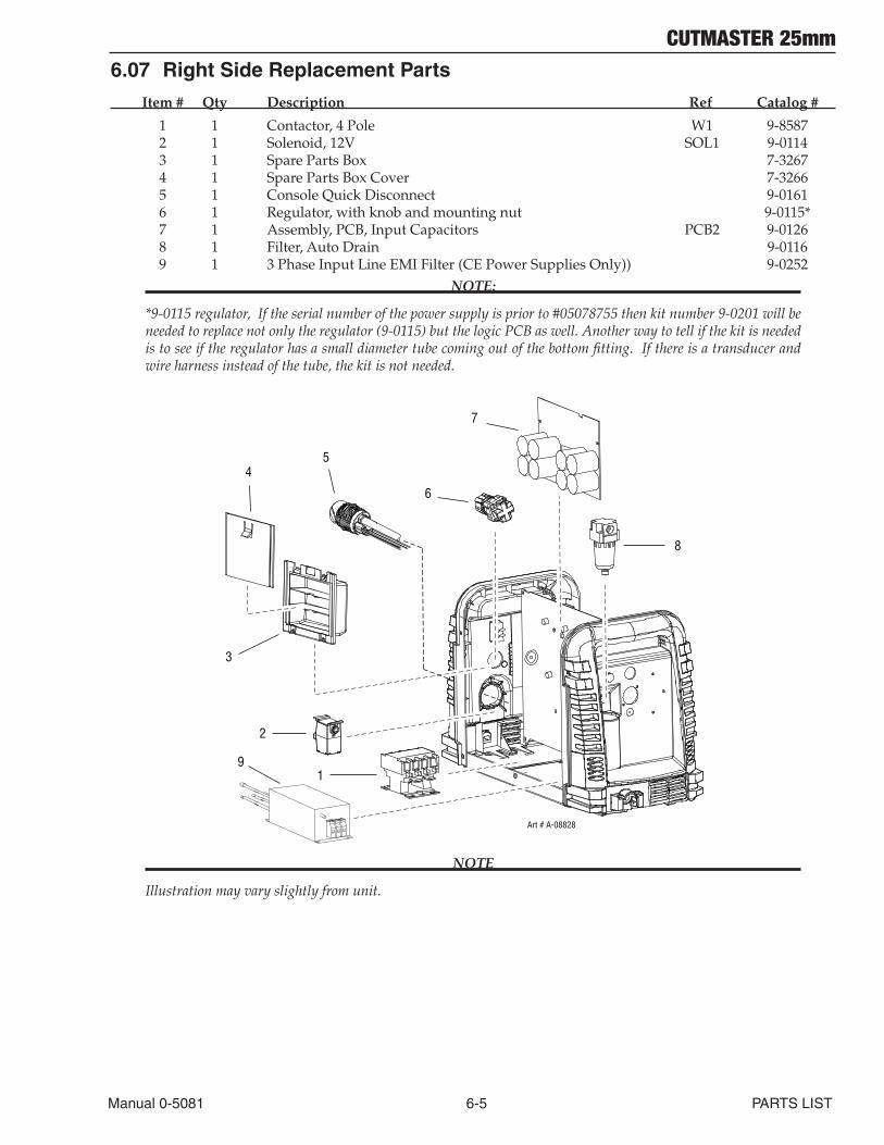
CUTMASTER 25mm
Manual 0-5081 6-5 PARTS LIST
6.07 Right Side Replacement Parts
Item # Qty Description Ref Catalog #
1 1 Contactor, 4 Pole W1 9-8587 2 1 Solenoid, 12V SOL1 9-0114 3 1 Spare Parts Box 7-3267 4 1 Spare Parts Box Cover 7-3266 5 1 Console Quick Disconnect 9-0161 6 1 Regulator, with knob and mounting nut 9-0115* 7 1 Assembly, PCB, Input Capacitors PCB2 9-0126 8 1 Filter, Auto Drain 9-0116 9 1 3 Phase Input Line EMI Filter (CE Power Supplies Only)) 9-0252
NOTE:
*9-0115 regulator, If the serial number of the power supply is prior to #05078755 then kit number 9-0201 will be needed to replace not only the regulator (9-0115) but the logic PCB as well. Another way to tell if the kit is needed is to see if the regulator has a small diameter tube coming out of the bottom fitting. If there is a transducer and wire harness instead of the tube, the kit is not needed.
1
2
3
5
6
7
Art # A-08828
4
8
9
NOTE
Illustration may vary slightly from unit.
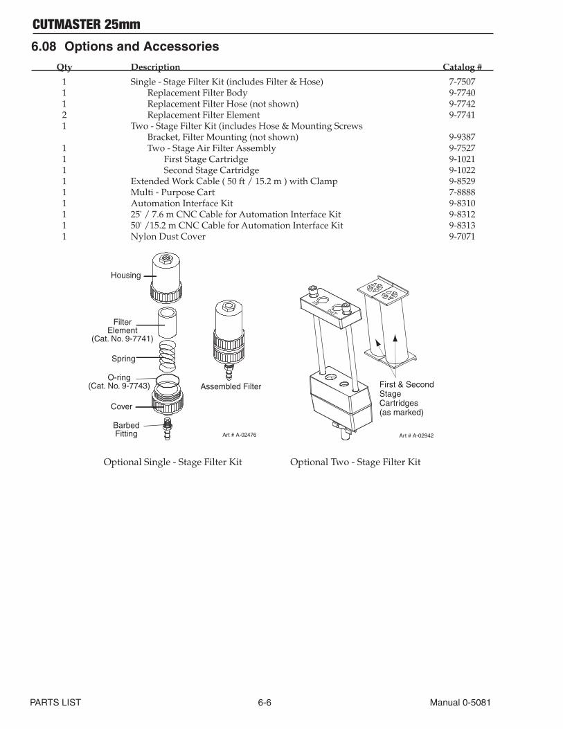
CUTMASTER 25mm
PARTS LIST 6-6 Manual 0-5081
6.08 Options and Accessories
Qty Description Catalog #
1 Single - Stage Filter Kit (includes Filter & Hose) 7-7507 1 Replacement Filter Body 9-7740 1 Replacement Filter Hose (not shown) 9-7742 2 Replacement Filter Element 9-7741 1 Two - Stage Filter Kit (includes Hose & Mounting Screws Bracket, Filter Mounting (not shown) 9-9387 1 Two - Stage Air Filter Assembly 9-7527 1 First Stage Cartridge 9-1021 1 Second Stage Cartridge 9-1022 1 Extended Work Cable ( 50 ft / 15.2 m ) with Clamp 9-8529 1 Multi - Purpose Cart 7-8888 1 Automation Interface Kit 9-8310 1 25' / 7.6 m CNC Cable for Automation Interface Kit 9-8312 1 50' /15.2 m CNC Cable for Automation Interface Kit 9-8313 1 Nylon Dust Cover 9-7071
Art # A-02476
FilterElement
(Cat. No. 9-7741)
Housing
Cover
BarbedFitting
Spring
Assembled FilterO-ring
(Cat. No. 9-7743)
First & Second StageCartridges (as marked)
Art # A-02942
Optional Single - Stage Filter Kit Optional Two - Stage Filter Kit
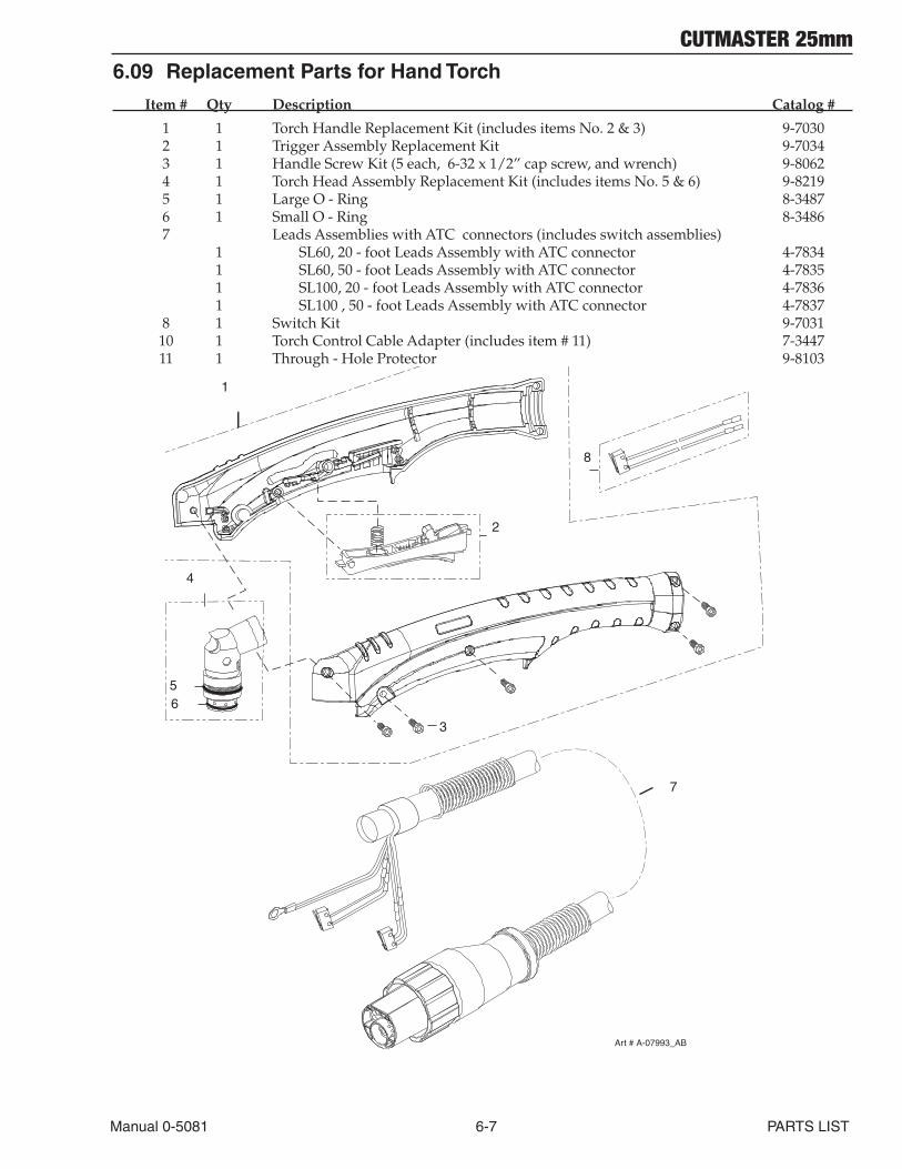
CUTMASTER 25mm
Manual 0-5081 6-7 PARTS LIST
6.09 Replacement Parts for Hand Torch
Item # Qty Description Catalog #
1 1 Torch Handle Replacement Kit (includes items No. 2 & 3) 9-7030 2 1 Trigger Assembly Replacement Kit 9-7034 3 1 Handle Screw Kit (5 each, 6-32 x 1/2” cap screw, and wrench) 9-8062 4 1 Torch Head Assembly Replacement Kit (includes items No. 5 & 6) 9-8219 5 1 Large O - Ring 8-3487 6 1 Small O - Ring 8-3486 7 Leads Assemblies with ATC connectors (includes switch assemblies) 1 SL60, 20 - foot Leads Assembly with ATC connector 4-7834 1 SL60, 50 - foot Leads Assembly with ATC connector 4-7835 1 SL100, 20 - foot Leads Assembly with ATC connector 4-7836 1 SL100 , 50 - foot Leads Assembly with ATC connector 4-7837 8 1 Switch Kit 9-7031 10 1 Torch Control Cable Adapter (includes item # 11) 7-3447 11 1 Through - Hole Protector 9-8103
7
56
3
4
2
Art # A-07993_AB
1
8
CUTMASTER 25mm
PARTS LIST 6-8 Manual 0-5081
6.10 Replacement Parts - for Mechanized Torches with Unshielded Leads
Item No. Qty Description Catalog No.
1 1 Torch Head Assembly without leads (includes items 2, 3, and 14) 9-8220 2 1 Large O - Ring 8-3487 3 1 Small O - Ring 8-3486 4 1 PIP Switch Kit 9-7036 5 Unshielded Mechanized Leads Assemblies with ATC connectors 1 5 - foot / 1.5 m Leads Assembly with ATC connector 4-7842 1 10 - foot / 3.05 m Leads Assembly with ATC connector 4-7843 1 25 - foot / 7.6 m Leads Assembly with ATC connector 4-7844 1 50 - foot / 15.2 m Leads Assembly with ATC connector 4-7845 6 1 11” / 279 mm Rack 9-7041 7 1 11” / 279 mm Mounting Tube 9-7043 8 1 End Cap Assembly 9-7044 9 2 Body, Mounting, Pinch Block 9-4513 10 1 Pin, Mounting, Pinch Block 9-4521 11 1 Torch Holder Sleeve 7-2896 12 1 PIP Plunger and Return Spring Kit 9-7045 1 Pinion Assembly (Not shown) 7-2827 1 5” / 126 mm Positioning Tube (Not shown) 9-7042
NOTE
* Does not include Control Cable Adapter or Through - Hole Protector.
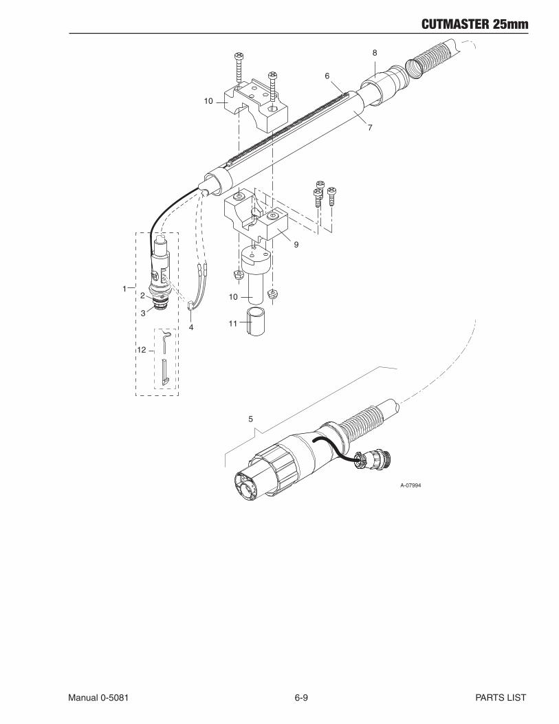
CUTMASTER 25mm
Manual 0-5081 6-9 PARTS LIST
A-07994
6
1
4
2
3
5
7
8
9
10
12
11
10
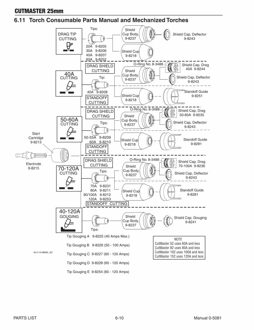
CUTMASTER 25mm
PARTS LIST 6-10 Manual 0-5081
6.11 Torch Consumable Parts Manual and Mechanized Torches
StartCartridge9-8213
Electrode9-8215
Tips:
20A 9-820530A 9-820640A 9-820760A 9-8252
Tip Gouging A 9-8225 (40 Amps Max.)
Tip Gouging B 9-8226 (50 - 100 Amps)
Tip Gouging C 9-8227 (60 - 120 Amps)
Tip Gouging D 9-8228 (60 - 120 Amps)
Tip Gouging E 9-8254 (60 - 120 Amps)
Shield Cap, Gouging 9-8241
Shield Cap, Drag40A 9-8244
40A 9-8208
50-55A 9-8209 60A 9-8210
70A 9-8231 80A 9-821190/100A 9-8212
120A 9-8253
Shield Cap, Drag50-60A 9-8235
Shield Cap, Drag70-100A 9-8236
Shield Cup Body,
9-8237
70-120A
50-60A
40A
Shield Cap, Deflector9-8243
Shield Cup Body,
9-8237
Shield Cup 9-8218
Tip:
Tips:
Tips:
Tips:
DRAG TIP CUTTING
40-120AGOUGING
CUTTING
CUTTING
CUTTING
Art # A-08065_AC
DRAG SHIELD CUTTING
Shield Cap, Deflector9-8243
Shield Cup Body,
9-8237
Shield Cup 9-8218
O-Ring No. 8-3488
Standoff Guide 9-8281
Shield Cap, Deflector9-8243
Shield Cup Body,
9-8237
Shield Cup 9-8218
O-Ring No. 8-3488
STANDOFF CUTTING
DRAG SHIELD CUTTING
Standoff Guide 9-8281
STANDOFF CUTTING
DRAG SHIELD CUTTING
STANDOFF CUTTING
Shield Cap, Deflector9-8243
Shield Cup Body,
9-8237
Shield Cup 9-8218
O-Ring No. 8-3488
Standoff Guide 9-8251
NOTECutMaster 52 uses 60A and lessCutMaster 82 uses 80A and lessCutMaster 102 uses 100A and lessCutMaster 152 uses 120A and less
CUTMASTER 25mm
Manual 0-5081 7-1 PARTS REPLACEMENT
SECTION 7: REPLACEMENT PROCEDURES
7.01 Scope
This section describes parts replacement procedures which may be performed on the CutMaster 25mm Power Supply.
Under no circumstances are field repairs to be attempted on Printed Circuits or other subassemblies of this unit. Evidence of unauthorized repairs may void the factory warranty.
7.02 Anti-Static Handling Procedures
A. General
Caution
PC Boards can be irreparably damaged by im-proper handling due to electrostatic discharge (ESD).
Replacement PC Boards are shipped in a protective en-closure to prevent damage from electrostatic discharge (ESD) during shipping. A ground strap is included with each replacement board to prevent static damage during installation.
! WARNINGS
Read and understand these instructions and the instructions on the grounding wrist strap package before opening the equipment enclo-sure or removing the replacement PC board from its protective enclosure.
Disconnect primary power to the system before disassembling the torch, torch leads, or power supply enclosure.
Where these instructions include specific torquing instructions, failure to torque prop-erly will cause component damage.
Do not operate the equipment or test equip-ment under power while wearing the ground-ing wrist strap.
B. Procedure
1. Open the wrist strap and unwrap the first two folds of the band. Wrap the adhesive side firmly around your wrist.
2. Unroll the rest of the band and peel the liner from the copper foil at the opposite end.
3. Attach the copper foil to a convenient and ex-posed electrical ground.
4. Connect the equipment primary cable ground to the same electrical ground as the wrist strap.
5. Open the equipment enclosure and remove the failed PC board.
6. Carefully open the ESD protective bag and re-move the replacement PC Board.
7. Install the replacement PC Board in the equip-ment and make all necessary connections.
8. Place the failed PC Board in the ESD protective bag and seal for return shipping.
9. Replace the power supply cover.
10. Remove the grounding wrist strap from your wrist and from the electrical ground connection before reconnecting primary power to the equip-ment.
7.03 Parts Replacement - General Information
The parts replacement procedures described in this manual, except for filter replacement, require that the Power Supply be disassembled. The part to be replaced will determine to what extent the Power Supply must be disassembled.
Before removing any connection mark each wire with the connection designation. When reassembling make sure the wires go to the proper terminals.
Note the routing of wires and make sure the wires are put back in the same place when re-assembling the unit.
Each subsection is referenced to Section 6 for parts lists and overall detailed drawings.
WARNING
Disconnect primary power from the source before opening or disassembling the power supply.
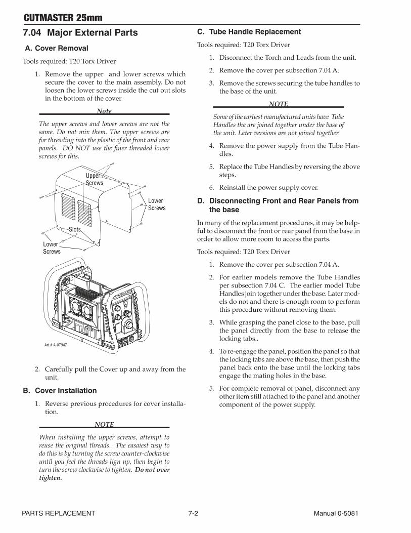
CUTMASTER 25mm
PARTS REPLACEMENT 7-2 Manual 0-5081
7.04 Major External Parts
A. Cover Removal
Tools required: T20 Torx Driver
1. Remove the upper and lower screws which secure the cover to the main assembly. Do not loosen the lower screws inside the cut out slots in the bottom of the cover.
Note
The upper screws and lower screws are not the same. Do not mix them. The upper screws are for threading into the plastic of the front and rear panels. DO NOT use the finer threaded lower screws for this.
UpperScrews
Lower Screws
Lower Screws
Art # A-07947
Slots
2. Carefully pull the Cover up and away from the unit.
B. Cover Installation
1. Reverse previous procedures for cover installa-tion.
NOTE
When installing the upper screws, attempt to reuse the original threads. The easaiest way to do this is by turning the screw counter-clockwise until you feel the threads lign up, then begin to turn the screw clockwise to tighten. Do not over tighten.
C. Tube Handle Replacement
Tools required: T20 Torx Driver
1. Disconnect the Torch and Leads from the unit.
2. Remove the cover per subsection 7.04 A.
3. Remove the screws securing the tube handles to the base of the unit.
NOTE
Some of the earliest manufactured units have Tube Handles tha are joined together under the base of the unit. Later versions are not joined together.
4. Remove the power supply from the Tube Han-dles.
5. Replace the Tube Handles by reversing the above steps.
6. Reinstall the power supply cover.
D. Disconnecting Front and Rear Panels from the base
In many of the replacement procedures, it may be help-ful to disconnect the front or rear panel from the base in order to allow more room to access the parts.
Tools required: T20 Torx Driver
1. Remove the cover per subsection 7.04 A.
2. For earlier models remove the Tube Handles per subsection 7.04 C. The earlier model Tube Handles join together under the base. Later mod-els do not and there is enough room to perform this procedure without removing them.
3. While grasping the panel close to the base, pull the panel directly from the base to release the locking tabs..
4. To re-engage the panel, position the panel so that the locking tabs are above the base, then push the panel back onto the base until the locking tabs engage the mating holes in the base.
5. For complete removal of panel, disconnect any other item still attached to the panel and another component of the power supply.
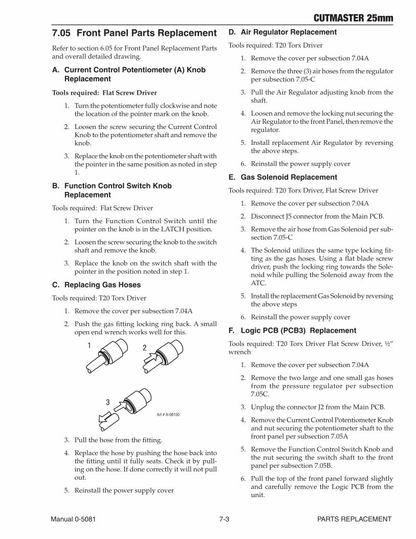
CUTMASTER 25mm
Manual 0-5081 7-3 PARTS REPLACEMENT
7.05 Front Panel Parts Replacement
Refer to section 6.05 for Front Panel Replacement Parts and overall detailed drawing.
A. Current Control Potentiometer (A) Knob Replacement
Tools required: Flat Screw Driver
1. Turn the potentiometer fully clockwise and note the location of the pointer mark on the knob.
2. Loosen the screw securing the Current Control Knob to the potentiometer shaft and remove the knob.
3. Replace the knob on the potentiometer shaft with the pointer in the same position as noted in step 1.
B. Function Control Switch Knob Replacement
Tools required: Flat Screw Driver
1. Turn the Function Control Switch until the pointer on the knob is in the LATCH position.
2. Loosen the screw securing the knob to the switch shaft and remove the knob.
3. Replace the knob on the switch shaft with the pointer in the position noted in step 1.
C. Replacing Gas Hoses
Tools required: T20 Torx Driver
1. Remove the cover per subsection 7.04A
2. Push the gas fitting locking ring back. A small open end wrench works well for this.
2
3
1
Art # A-08150
3. Pull the hose from the fitting.
4. Replace the hose by pushing the hose back into the fitting until it fully seats. Check it by pull-ing on the hose. If done correctly it will not pull out.
5. Reinstall the power supply cover
D. Air Regulator Replacement
Tools required: T20 Torx Driver
1. Remove the cover per subsection 7.04A
2. Remove the three (3) air hoses from the regulator per subsection 7.05-C
3. Pull the Air Regulator adjusting knob from the shaft.
4. Loosen and remove the locking nut securing the Air Regulator to the front Panel, then remove the regulator.
5. Install replacement Air Regulator by reversing the above steps.
6. Reinstall the power supply cover
E. Gas Solenoid Replacement
Tools required: T20 Torx Driver, Flat Screw Driver
1. Remove the cover per subsection 7:04A
2. Disconnect J5 connector from the Main PCB.
3. Remove the air hose from Gas Solenoid per sub-section 7.05-C
4. The Solenoid utilizes the same type locking fit-ting as the gas hoses. Using a flat blade screw driver, push the locking ring towards the Sole-noid while pulling the Solenoid away from the ATC.
5. Install the replacement Gas Solenoid by reversing the above steps
6. Reinstall the power supply cover
F. Logic PCB (PCB3) Replacement
Tools required: T20 Torx Driver Flat Screw Driver, ½” wrench
1. Remove the cover per subsection 7.04A
2. Remove the two large and one small gas hoses from the pressure regulator per subsection 7.05C.
3. Unplug the connector J2 from the Main PCB.
4. Remove the Current Control Potentiometer Knob and nut securing the potentiometer shaft to the front panel per subsection 7.05A
5. Remove the Function Control Switch Knob and the nut securing the switch shaft to the front panel per subsection 7.05B.
6. Pull the top of the front panel forward slightly and carefully remove the Logic PCB from the unit.
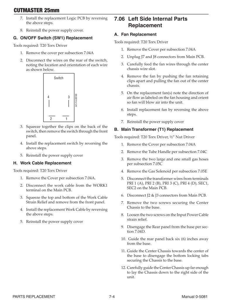
CUTMASTER 25mm
PARTS REPLACEMENT 7-4 Manual 0-5081
7. Install the replacement Logic PCB by reversing the above steps.
8. Reinstall the power supply cover.
G. ON/OFF Switch (SW1) Replacement
Tools required: T20 Torx Driver
1. Remove the cover per subsection 7.04A
2. Disconnect the wires on the rear of the switch, noting the location and orientation of each wire as shown below.
Switch
4 3
2 1
Art #
A-0
8169
3. Squeeze together the clips on the back of the switch, then remove the switch through the front panel.
4. Install the replacement switch by reversing the above steps.
5. Reinstall the power supply cover
H. Work Cable Replacement
Tools required: T20 Torx Driver
1. Remove the Cover per subsection 7.04A.
2. Disconnect the work cable from the WORK1 terminal on the Main PCB.
3. Squeeze the top and bottom of the Work Cable Strain Relief and remove from the front panel.
4. Install the replacement Work Cable by reversing the above steps.
5. Reinstall the power supply cover
7.06 Left Side Internal Parts Replacement
A. Fan Replacement
Tools required: T20 Torx Driver
1. Remove the Cover per subsection 7.04A
2. Unplug J7 and J8 connectors from Main PCB.
3. Carefully feed the fan wires through the center chassis wire slot.
4. Remove the fan by pushing the fan retaining clips apart and pulling the fan out of the center chassis.
5. On the replacement fan(s) note the direction of air flow as labeled on the fan housing and orient so fan will blow air into the unit.
6. Install replacement fan by reversing the above steps.
7. Reinstall the power supply cover
B. Main Transformer (T1) Replacement
Tools required: T20 Torx Driver, ½” Nut Driver
1. Remove the Cover per subsection 7.04A
2. Remove the Tube Handle per subsection 7.04C
3. Remove the two large and one small gas hoses per subsection 7.05C
4. Remove the Gas Solenoid per subsection 7.05E
5. Disconnect the transformer wires from terminals PRI 1 (A), PRI 2 (B), PRI 3 (C), PRI 4 (D), SEC1, SEC2 on the Main PCB.
6. Disconnect J2 & J3 connectors from Main PCB.
7. Remove the two screws securing the Center Chassis to the base.
8. Loosen the two screws on the Input Power Cable strain relief.
9. Disengage the Rear panel from the base per sec-tion 7.04D.
10. Guide the rear panel back six (6) inches away from the base.
11. Guide the Center Chassis towards the center of the base to disengage the bottom locking tabs securing the Chassis to the base.
12. Carefully guide the Center Chassis up far enough to lay the Chassis down to the right side of the unit.
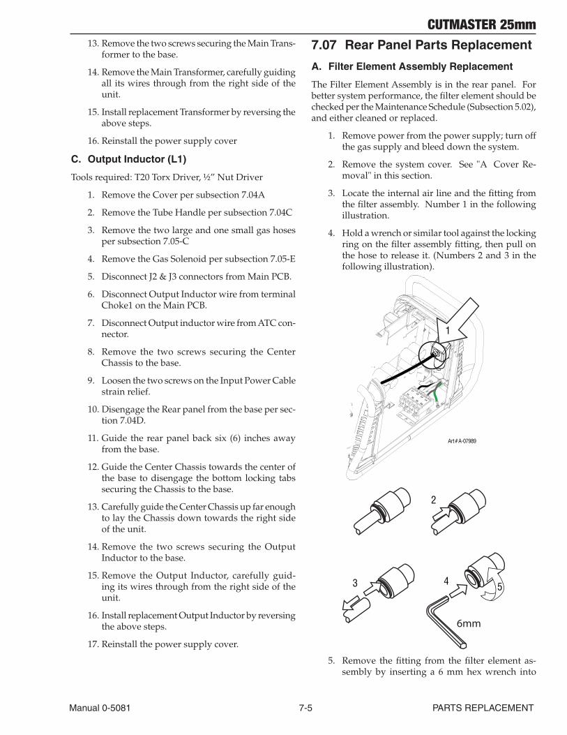
CUTMASTER 25mm
Manual 0-5081 7-5 PARTS REPLACEMENT
13. Remove the two screws securing the Main Trans-former to the base.
14. Remove the Main Transformer, carefully guiding all its wires through from the right side of the unit.
15. Install replacement Transformer by reversing the above steps.
16. Reinstall the power supply cover
C. Output Inductor (L1)
Tools required: T20 Torx Driver, ½” Nut Driver
1. Remove the Cover per subsection 7.04A
2. Remove the Tube Handle per subsection 7.04C
3. Remove the two large and one small gas hoses per subsection 7.05-C
4. Remove the Gas Solenoid per subsection 7.05-E
5. Disconnect J2 & J3 connectors from Main PCB.
6. Disconnect Output Inductor wire from terminal Choke1 on the Main PCB.
7. Disconnect Output inductor wire from ATC con-nector.
8. Remove the two screws securing the Center Chassis to the base.
9. Loosen the two screws on the Input Power Cable strain relief.
10. Disengage the Rear panel from the base per sec-tion 7.04D.
11. Guide the rear panel back six (6) inches away from the base.
12. Guide the Center Chassis towards the center of the base to disengage the bottom locking tabs securing the Chassis to the base.
13. Carefully guide the Center Chassis up far enough to lay the Chassis down towards the right side of the unit.
14. Remove the two screws securing the Output Inductor to the base.
15. Remove the Output Inductor, carefully guid-ing its wires through from the right side of the unit.
16. Install replacement Output Inductor by reversing the above steps.
17. Reinstall the power supply cover.
7.07 Rear Panel Parts Replacement
A. Filter Element Assembly Replacement
The Filter Element Assembly is in the rear panel. For better system performance, the filter element should be checked per the Maintenance Schedule (Subsection 5.02), and either cleaned or replaced.
1. Remove power from the power supply; turn off the gas supply and bleed down the system.
2. Remove the system cover. See "A Cover Re-moval" in this section.
3. Locate the internal air line and the fitting from the filter assembly. Number 1 in the following illustration.
4. Hold a wrench or similar tool against the locking ring on the filter assembly fitting, then pull on the hose to release it. (Numbers 2 and 3 in the following illustration).
Art # A-07989
1
2
3 4 5
6mm
5. Remove the fitting from the filter element as-sembly by inserting a 6 mm hex wrench into
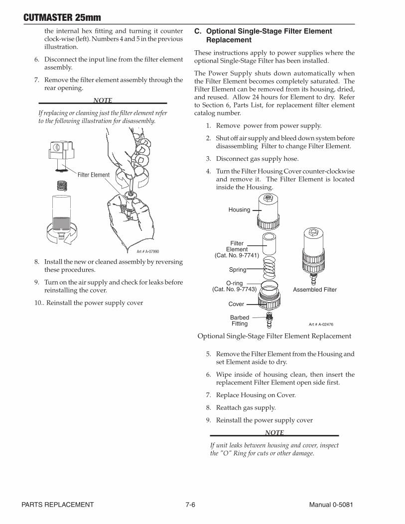
CUTMASTER 25mm
PARTS REPLACEMENT 7-6 Manual 0-5081
the internal hex fitting and turning it counter clock-wise (left). Numbers 4 and 5 in the previous illustration.
6. Disconnect the input line from the filter element assembly.
7. Remove the filter element assembly through the rear opening.
NOTE
If replacing or cleaning just the filter element refer to the following illustration for disassembly.
Art # A-07990
Filter Element
8. Install the new or cleaned assembly by reversing these procedures.
9. Turn on the air supply and check for leaks before reinstalling the cover.
10.. Reinstall the power supply cover
C. Optional Single-Stage Filter Element Replacement
These instructions apply to power supplies where the optional Single-Stage Filter has been installed.
The Power Supply shuts down automatically when the Filter Element becomes completely saturated. The Filter Element can be removed from its housing, dried, and reused. Allow 24 hours for Element to dry. Refer to Section 6, Parts List, for replacement filter element catalog number.
1. Remove power from power supply.
2. Shut off air supply and bleed down system before disassembling Filter to change Filter Element.
3. Disconnect gas supply hose.
4. Turn the Filter Housing Cover counter-clockwise and remove it. The Filter Element is located inside the Housing.
Art # A-02476
FilterElement
(Cat. No. 9-7741)
Housing
Cover
BarbedFitting
Spring
Assembled FilterO-ring
(Cat. No. 9-7743)
Optional Single-Stage Filter Element Replacement
5. Remove the Filter Element from the Housing and set Element aside to dry.
6. Wipe inside of housing clean, then insert the replacement Filter Element open side first.
7. Replace Housing on Cover.
8. Reattach gas supply.
9. Reinstall the power supply cover
NOTE
If unit leaks between housing and cover, inspect the "O" Ring for cuts or other damage.
CUTMASTER 25mm
Manual 0-5081 7-7 PARTS REPLACEMENT
7.08 Right Side Internal Parts Replacement
A. Capacitor PCB (PCB2) Replacement
Tools required: T20 Torx Driver
1. Remove the Cover per subsection 7.04A
2. Remove the eight screws securing PCB2 to the Main PCB.
3. Install the replacement PCB by reversing the above steps.
B. Main PCB (PCB1) Replacement
Tools required: T20 Torx Driver
1. Remove the Cover per subsection 7.04A
2. Remove the two large gas hoses per subsection 7.05-C
3. Remove the Gas Solenoid per subsection 5.05E
4. Remove Capacitor PCB per subsection 7.08 A.
5. Disconnect the wires and connectors from the PCB, noting the location and orientation of each wire and connector.
6. Remove the four (4) mounting screws securing the PCB to the center chassis.
7. Carefully guide the PCB assembly up and out of the unit.
8. Install the replacement PCB by reversing the above steps.
9. Reinstall the power supply cover
C. Main Contactor (W1) Replacement
Tools required: T20 Torx Driver
1. Remove the Cover per subsection 7.04A
2. Remove all wires from W1, noting the location and orientation of each wire
3. Loosen the two (2) Torx head screws securing the Main Contactor to the base.
4. Slide the contactor towards the rear of the unit slightly to allow the contactor to clear the mount-ing screws.
5. Lift Main Contactor up and out of the unit.
6. Install the replacement Contactor by reversing the above steps.
7 Reinstall the power supply cover.

CUTMASTER 25mm
PARTS REPLACEMENT 7-8 Manual 0-5081
This Page Intentionally Blank
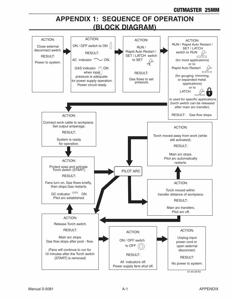
CUTMASTER 25MM
Manual 0-5081 A-1 APPENDIX
APPENDIX 1: SEQUENCE OF OPERATION (BLOCK DIAGRAM)
ACTION:
ON / OFF switch to ON
RESULT:
AC indicator ON.
GAS indicator ON when input
pressure is adequate for power supply operation.
Power circuit ready.
ACTION:
Protect eyes and activate Torch switch (START)
RESULT:
Fans turn on. Gas flows briefly, then stops.Gas restarts.
DC indicator ONPilot arc established.
Art #A-08793
ACTION:
Unplug inputpower cord or open externaldisconnect.
RESULT:
No power to system.
ACTION:
Connect work cable to workpiece. Set output amperage.
RESULT:
System is readyfor operation.
ACTION:
RUN / Rapid Auto Restart / SET / LATCH switch
to SET
RESULT:
Gas flows to set pressure.
ACTION:RUN / Rapid Auto Restart /
SET / LATCHswitch to RUN
(for most applications) or to
Rapid Auto Restart
(for gouging, trimming,or expanded metal
applications)or to
LATCH
is used for specific applications (torch switch can be released
after main arc transfer).
RESULT: Gas flow stops.
ACTION:
Release Torch switch.
RESULT:
Main arc stops.Gas flow stops after post - flow.
(Fans will continue to run for 10 minutes after the Torch switch
[START] is removed)
ACTION:
ON / OFF switch
to OFF
RESULT:
All indicators off.Power supply fans shut off.
ACTION:
Close externaldisconnect switch.
RESULT:
Power to system.
ACTION:
Torch moved within transfer distance of workpiece.
RESULT:
Main arc transfers.Pilot arc off.
PILOT ARC
ACTION:
Torch moved away from work (while still activated).
RESULT:
Main arc stops.Pilot arc automatically
restarts.
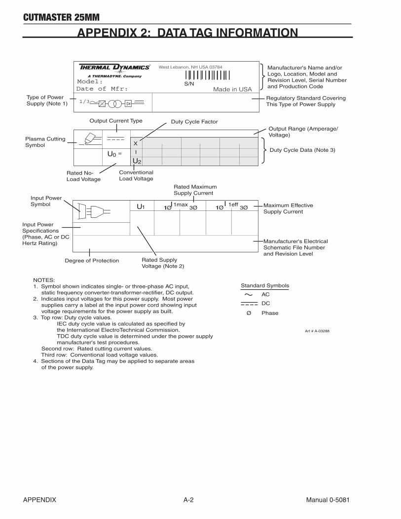
CUTMASTER 25MM
APPENDIX A-2 Manual 0-5081
1/3 ff12
West Lebanon, NH USA 03784
Made in USAModel:
U1 1 11max 1effI I
U2
3Ø 3Ø1Ø1Ø
S/N
U0 =
X
Standard Symbols
Ø
AC
DC
Phase
NOTES:1. Symbol shown indicates single- or three-phase AC input, static frequency converter-transformer-rectifier, DC output.2. Indicates input voltages for this power supply. Most power supplies carry a label at the input power cord showing input voltage requirements for the power supply as built. 3. Top row: Duty cycle values. IEC duty cycle value is calculated as specified by the International ElectroTechnical Commission. TDC duty cycle value is determined under the power supply manufacturer's test procedures. Second row: Rated cutting current values. Third row: Conventional load voltage values.4. Sections of the Data Tag may be applied to separate areas of the power supply.
I
Art # A-03288
Date of Mfr:
Output Range (Amperage/Voltage)
Type of PowerSupply (Note 1)
Output Current Type
Rated No-Load Voltage
Plasma Cutting Symbol
Manufacturer's Name and/orLogo, Location, Model andRevision Level, Serial Number and Production Code
ConventionalLoad Voltage
Regulatory Standard CoveringThis Type of Power Supply
Duty Cycle Data (Note 3)
Duty Cycle Factor
Input PowerSpecifications (Phase, AC or DCHertz Rating)
Input PowerSymbol
Rated Supply Voltage (Note 2)
Rated MaximumSupply Current
Maximum Effective Supply Current
Degree of Protection
Manufacturer's ElectricalSchematic File Numberand Revision Level
APPENDIX 2: DATA TAG INFORMATION
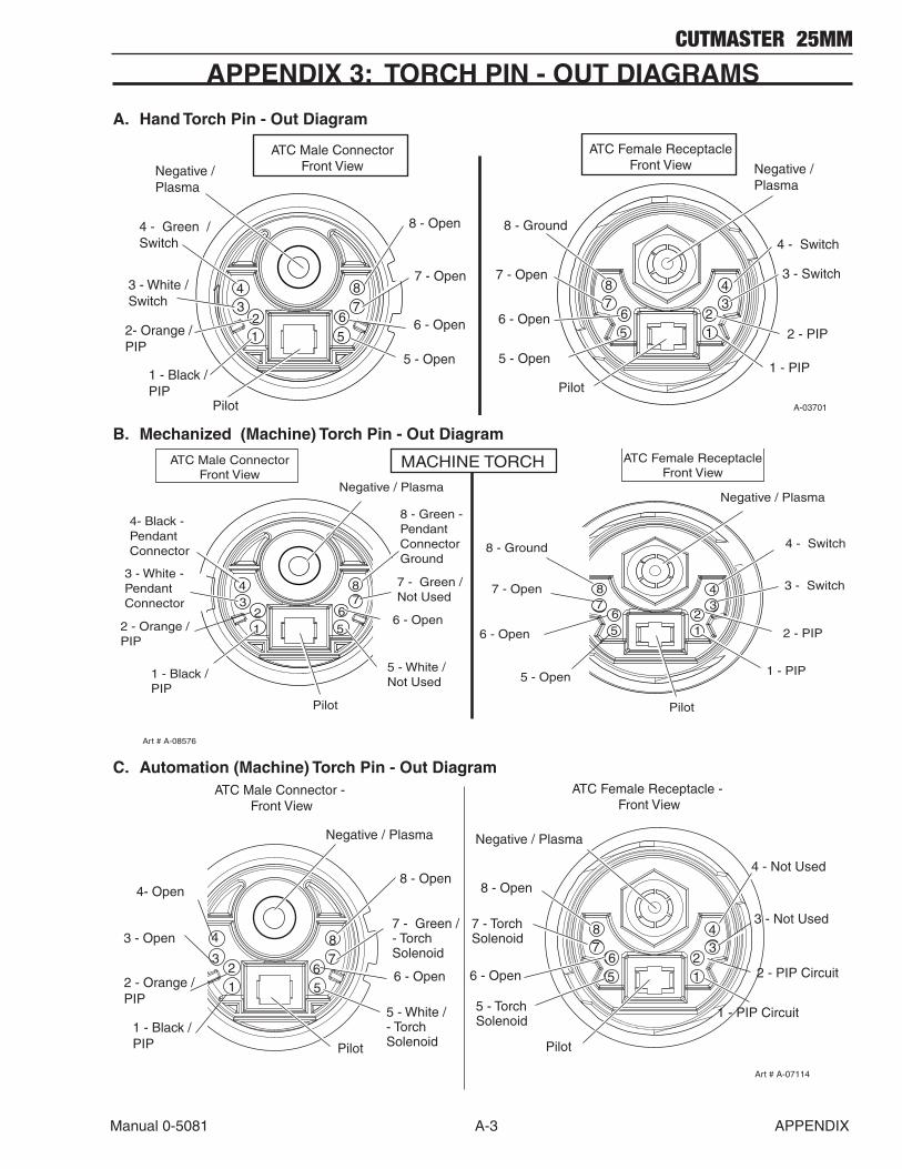
CUTMASTER 25MM
Manual 0-5081 A-3 APPENDIX
APPENDIX 3: TORCH PIN - OUT DIAGRAMS
A. Hand Torch Pin - Out Diagram
12
34
56
78
5
678
12
34
ATC Female ReceptacleFront View
PilotPilot
6 - Open
7 - Open
8 - Open
5 - Open
Negative / Plasma
6 - Open
7 - Open
5 - Open
2 - PIP
3 - Switch
4 - Switch
1 - PIP
4 - Green / Switch
2- Orange /PIP
3 - White / Switch
1 - Black /PIP
Negative / Plasma
8 - Ground
ATC Male ConnectorFront View
A-03701
B. Mechanized (Machine) Torch Pin - Out DiagramATC Female Receptacle
Front ViewATC Male Connector
Front ViewNegative / Plasma
3 - White - PendantConnector
4- Black - PendantConnector
2 - Orange /PIP
1 - Black /PIP
Pilot
2 - PIP
1 - PIP
6 - Open
7 - Open
5 - Open
8 - Ground
8 - Green - Pendant Connector Ground
5 - White /Not Used
7 - Green /Not Used
6 - Open
MACHINE TORCH
3 - Switch
4 - Switch
Art # A-08576
Negative / Plasma
Pilot
12
34
56
78
5
6
8
12
34
7
C. Automation (Machine) Torch Pin - Out DiagramATC Female Receptacle -
Front ViewATC Male Connector -
Front View
Negative / Plasma
Pilot
Negative / Plasma
6 - Open
7 - TorchSolenoid
5 - TorchSolenoid
8 - Open8 - Open
5 - White /- TorchSolenoid
7 - Green /- TorchSolenoid
56
78
12
3
4
Pilot
12
34
56
78
3 - Open
2 - Orange /PIP
1 - Black /PIP
4- Open
2 - PIP Circuit
1 - PIP Circuit
3 - Not Used
4 - Not Used
6 - Open
Art # A-07114
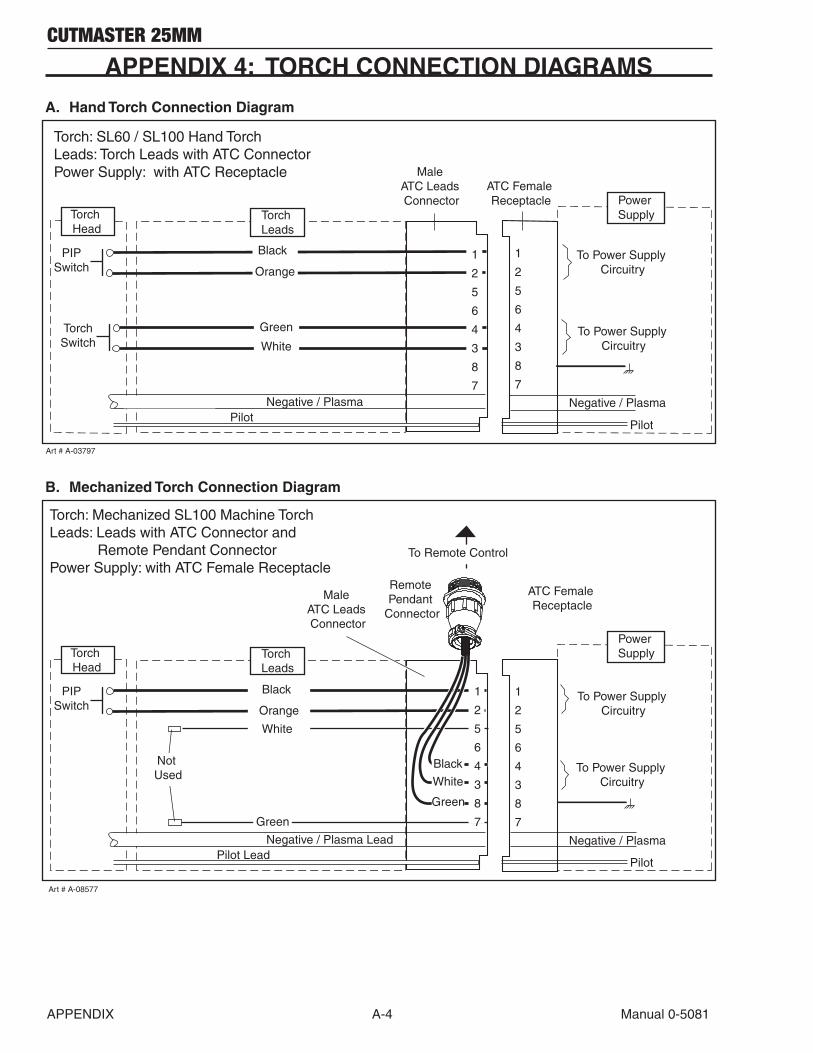
CUTMASTER 25MM
APPENDIX A-4 Manual 0-5081
APPENDIX 4: TORCH CONNECTION DIAGRAMS
A. Hand Torch Connection Diagram
Torch: SL60 / SL100 Hand TorchLeads: Torch Leads with ATC ConnectorPower Supply: with ATC Receptacle
Pilot
Negative / Plasma
Power Supply
PIPSwitch
Male ATC Leads Connector
ATC Female Receptacle
Pilot Negative / Plasma
Black
Orange
Torch Leads
Torch Head
To Power Supply Circuitry
Art # A-03797
1
2
5
6
4
3
8
7
1
2
5
6
4
3
8
7
TorchSwitch
Green
WhiteTo Power Supply
Circuitry
B. Mechanized Torch Connection Diagram
Torch: Mechanized SL100 Machine Torch Leads: Leads with ATC Connector and Remote Pendant ConnectorPower Supply: with ATC Female Receptacle
Pilot
Negative / Plasma
Power Supply
To Remote Control
Remote Pendant
Connector
PIPSwitch
Not Used
Male ATC Leads Connector
ATC Female Receptacle
Pilot LeadNegative / Plasma Lead
Torch Leads
Torch Head
Art # A-08577
1
2
5
6
4
3
8
7
To Power Supply Circuitry
Green
To Power Supply Circuitry
1
2
5
6
4
3
8
7
Black
White
Green
Black
Orange
White
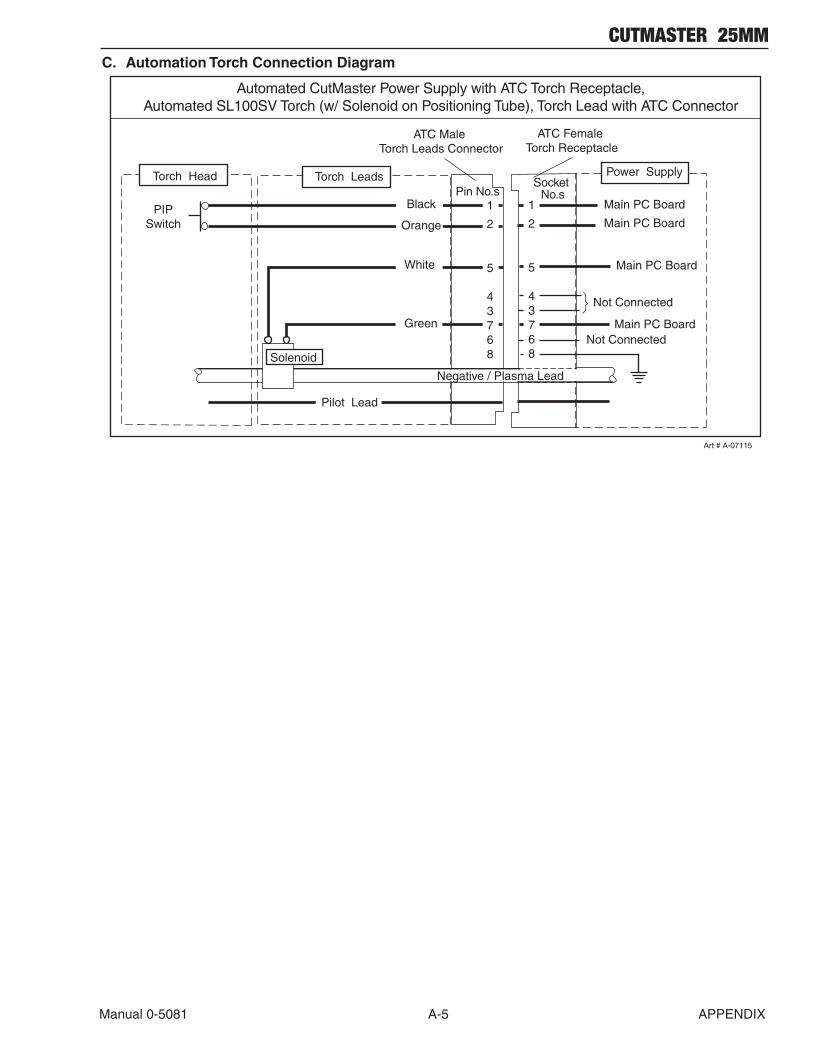
CUTMASTER 25MM
Manual 0-5081 A-5 APPENDIX
C. Automation Torch Connection Diagram
Automated CutMaster Power Supply with ATC Torch Receptacle,Automated SL100SV Torch (w/ Solenoid on Positioning Tube), Torch Lead with ATC Connector
Power Supply
PIPSwitch
ATC Male Torch Leads Connector
ATC Female Torch Receptacle
Negative / Plasma Lead
Pilot Lead
Art # A-07115
Pin No.sSocket
No.s1
2
5
43768
Main PC Board
1
2
5
43768
White
Black
Orange
Green Main PC Board
Solenoid
Torch LeadsTorch Head
Not Connected
Not Connected
Main PC Board
Main PC Board
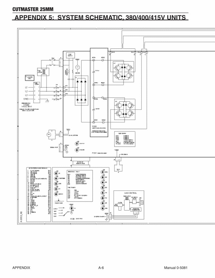
CUTMASTER 25MM
APPENDIX A-6 Manual 0-5081
APPENDIX 5: SYSTEM SCHEMATIC, 380/400/415V UNITS
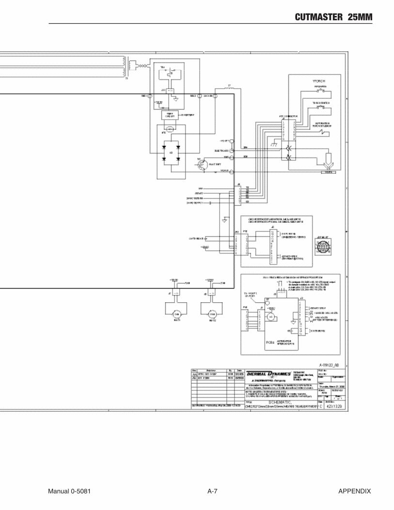
CUTMASTER 25MM
Manual 0-5081 A-7 APPENDIX

CUTMASTER 25MM
APPENDIX A-8 Manual 0-5081
APPENDIX 6: Publication History
Cover Date Rev. Change(s)
Jan 9, 2009 AA Manual released.
May 29, 2009 AB Updated 400V/600V schematic in appendix per ECOB1399

Thermadyne USA2800 Airport RoadDenton, Tx 76207 USATelephone: (940) 566-2000800-426-1888Fax: 800-535-0557
Thermadyne Canada2070 Wyecroft RoadOakville, OntarioCanada, L6L5V6Telephone: (905)-827-1111Fax: 905-827-3648
Thermadyne EuropeEurope BuildingChorley North Industrial ParkChorley, LancashireEngland, PR6 7BxTelephone: 44-1257-261755Fax: 44-1257-224800
Thermadyne, ChinaRM 102A685 Ding Xi RdChang Ning DistrictShanghai, PR, 200052Telephone: 86-21-69171135Fax: 86-21-69171139
Thermadyne Asia Sdn BhdLot 151, Jalan Industri 3/5ARawang Integrated Industrial Park - Jln Batu Arang48000 Rawang Selangor Darul EhsanWest MalaysiaTelephone: 603+ 6092 2988Fax : 603+ 6092 1085
Cigweld, Australia71 Gower StreetPreston, VictoriaAustralia, 3072Telephone: 61-3-9474-7400Fax: 61-3-9474-7510
Thermadyne ItalyOCIM, S.r.L.Via Benaco, 320098 S. GiulianoMilan, ItalyTel: (39) 0236546801Fax: (39) 0236546840
Thermadyne International2070 Wyecroft RoadOakville, OntarioCanada, L6L5V6Telephone: (905)-827-9777Fax: 905-827-9797
GLOBAL CUSTOMER SERVICE CONTACT

Corporate Headquarters16052 Swingley Ridge RoadSuite 300St. Louis, MO 63017Telephone: 636-728-3000Email: [email protected]