2585 Mounting Options - IndustrialZone
8
‘08 Series Notification Appliances 2585 s Industry, Inc. Building Technologies Division s Data Sheet Fire Safety & Security Products ‘08 Series Notification Appliances Mounting Options Mounting Diagrams / Mounting Matrixes / Mounting Notes ARCHITECT AND ENGINEER SPECIFICATIONS (713)-395-1508 Fax: (713) 893-6924 [email protected] www.industrialzone.com IndustrialZone P.O. Box 667306 Houston, Texas 77266 United States
Transcript of 2585 Mounting Options - IndustrialZone
‘08 Series Notification Appliances 2585 s Industry, Inc. Building Technologies Division
s Data Sheet
Fire Safety & Security Products
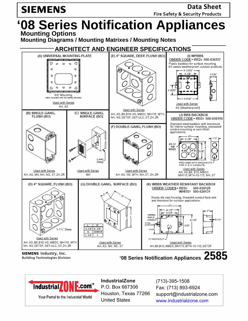
‘08 Series Notification Appliances Mounting Options Mounting Diagrams / Mounting Matrixes / Mounting Notes
ARCHITECT AND ENGINEER SPECIFICATIONS
(713)-395-1508Fax: (713) [email protected]
IndustrialZoneP.O. Box 667306Houston, Texas 77266United States
s Industry, Inc. Building Technologies Division
s Industry, Inc. Building Technologies Division
s Industry, Inc. Building Technologies Division
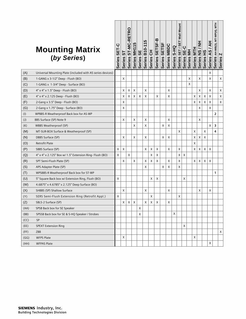
Mounting Matrix (by Series)
Serie
s SE
T-C
Se
ries
ST
Serie
s ST
-MC
-RET
RO
Se
ries
MH
115
Serie
s SE
Se
ries
B10
-115
Serie
s C
H
Serie
s SE
TSF-
B
Serie
s SE
TSF
Serie
s M
BD
C
Serie
s S-
HQ
Se
ries
SET
/ SET
Wal
l Mou
nt
Serie
s SE
-C
Serie
s M
H
Serie
s M
TH
Serie
s N
S / N
H
Serie
s H
S Se
ries
AS
/ AH
Se
ries
AH
-WB
(3),
MT-
WP(
4), M
TH
Serie
s Z
(A) Universal Mounting Plate (included with AS series devices) X (B) 1-GANG x 3-1/2” Deep - Flush (BO) X X X X X
(C) 1-GANG x 1-3/4” Deep - Surface (BO) X
(D) 4” x 4” x 1.5” Deep - Flush (BO) X X X X X X X X
(E) 4” x 4” x 2.125 Deep - Flush (BO) X X X X X X X X X X X X
(F) 2-Gang x 3.5” Deep - Flush (BO) X X X X X X
(G) 2-Gang x 1.75” Deep - Surface (BO) X X X (I) WPBBS-R Weatherproof Back box for AS-WP 2 (J) BBS Surface (SP) Note 9 X X X X X (K) WBBS Weatherproof (SP) X X X X X 3 (M) MT-SUR-BOX Surface & Weatherproof (SP) X X X 4 (N) DBBS Surface (SP) X X X X X X X X (O) Retrofit Plate X (P) SBBS Surface (SP) X X X X X X X X X X X (Q) 4” x 4” x 2.125” Box w/ 1.5” Extension Ring- Flush (BO) X X X X X X (R) SPT Semi-Flush Plate (SP) X X X X X X X X X X X (S) APS Adapter Plate (SP) X X X X (T) WPSBBS-R Weatherproof Back box for ST-WP 1 (U) 5” Square Back box w/ Extension Ring, Flush (BO) X X X X (W) 4.6875” x 4.6785” x 2.125” Deep Surface (BO) (X) SHBBS (SP) Shallow Surface X X X X X (Y) SERS Semi-Flush Extension Ring (Retrofit Appl.) X X X (Z) SBLS-2 Surface (SP) X X X X X X X (AA) SPSB Back box for SE Speaker X (BB) SPSSB Back box for SE & S-HQ Speaker / Strobes X X (CC) SP (EE) SPEXT Extension Ring X (FF) ZBB X
(GG) WFPS Plate X X
(HH) WFPAS Plate X

s Industry, Inc. Building Technologies Division
Mounting Matrix (by Model Number)
s Industry, Inc. Building Technologies Division
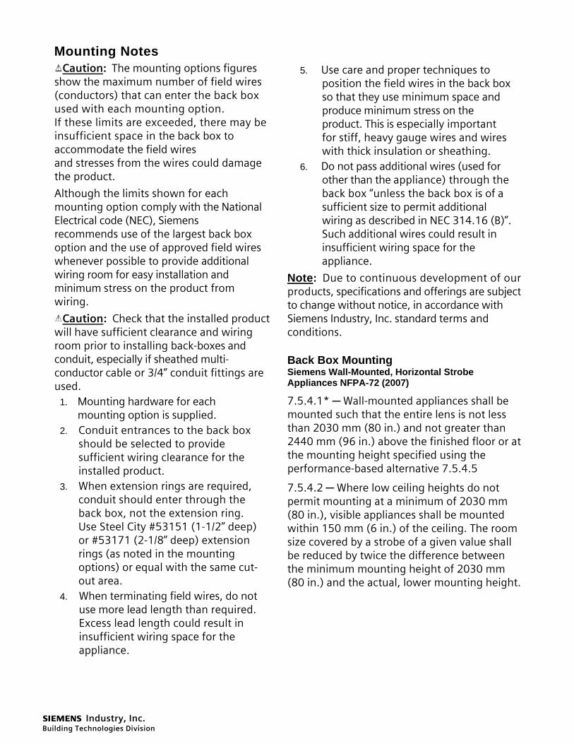
Mounting Notes Caution: The mounting options figures
show the maximum number of field wires (conductors) that can enter the back box used with each mounting option. If these limits are exceeded, there may be insufficient space in the back box to accommodate the field wires and stresses from the wires could damage the product.
Although the limits shown for each mounting option comply with the National Electrical code (NEC), Siemens recommends use of the largest back box option and the use of approved field wires whenever possible to provide additional wiring room for easy installation and minimum stress on the product from wiring.
Caution: Check that the installed product will have sufficient clearance and wiring room prior to installing back-boxes and conduit, especially if sheathed multi-conductor cable or 3/4” conduit fittings are used.
1. Mounting hardware for each mounting option is supplied.
2. Conduit entrances to the back box should be selected to provide sufficient wiring clearance for the installed product.
3. When extension rings are required, conduit should enter through the back box, not the extension ring. Use Steel City #53151 (1-1/2” deep) or #53171 (2-1/8” deep) extension rings (as noted in the mounting options) or equal with the same cut-out area.
4. When terminating field wires, do not use more lead length than required. Excess lead length could result in insufficient wiring space for the appliance.
5. Use care and proper techniques to position the field wires in the back box so that they use minimum space and produce minimum stress on the product. This is especially important for stiff, heavy gauge wires and wires with thick insulation or sheathing.
6. Do not pass additional wires (used for other than the appliance) through the back box “unless the back box is of a sufficient size to permit additional wiring as described in NEC 314.16 (B)”. Such additional wires could result in insufficient wiring space for the appliance.
Note: Due to continuous development of our products, specifications and offerings are subject to change without notice, in accordance with Siemens Industry, Inc. standard terms and conditions.
Back Box Mounting Siemens Wall-Mounted, Horizontal Strobe Appliances NFPA-72 (2007)
7.5.4.1* ─ Wall-mounted appliances shall be mounted such that the entire lens is not less than 2030 mm (80 in.) and not greater than 2440 mm (96 in.) above the finished floor or at the mounting height specified using the performance-based alternative 7.5.4.5
7.5.4.2 ─ Where low ceiling heights do not permit mounting at a minimum of 2030 mm (80 in.), visible appliances shall be mounted within 150 mm (6 in.) of the ceiling. The room size covered by a strobe of a given value shall be reduced by twice the difference between the minimum mounting height of 2030 mm (80 in.) and the actual, lower mounting height.
s Industry, Inc. Building Technologies Division
Series AS/AH
Audible Strobe
Series ST-MC-RETRO (Flush and Surface Retrofit Plate)
Horn Series NS
Strobe
Series Z and ST Strobe
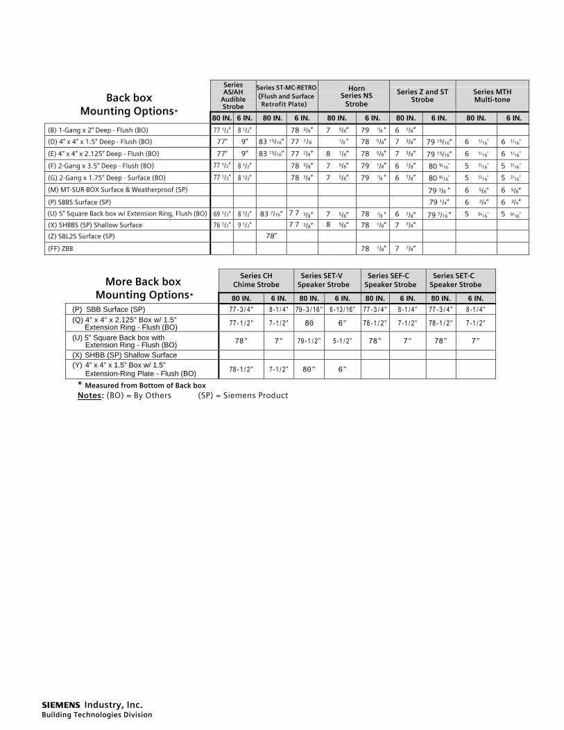
Series MTH Multi-tone Back box
Mounting Options* 80 IN. 6 IN. 80 IN. 6 IN. 80 IN. 6 IN. 80 IN. 6 IN. 80 IN. 6 IN.
(B) 1-Gang x 2” Deep - Flush (BO) 77 1/2” 8 1/2” 78 3/8” 7 5/8” 79 1/8 ” 6 7/8”
(D) 4” x 4” x 1.5” Deep - Flush (BO) 77” 9” 83 15/16” 77 7/8 1/8 ” 78 5/8” 7 3/8” 79 15/16” 6 1/16” 6 1/16”
(E) 4” x 4” x 2.125” Deep - Flush (BO) 77” 9” 83 15/16” 77 7/8” 8 1/8” 78 5/8” 7 3/8” 79 15/16” 6 1/16” 6 1/16”
(F) 2-Gang x 3.5” Deep - Flush (BO) 77 1/2” 8 1/2” 78 3/8” 7 5/8” 79 1/8” 6 7/8” 80 9/16” 5 7/16” 5 7/16”
(G) 2-Gang x 1.75” Deep - Surface (BO) 77 1/2” 8 1/2” 78 3/8” 7 5/8” 79 1/8 ” 6 7/8” 80 9/16” 5 7/16” 5 7/16”
(M) MT-SUR-BOX Surface & Weatherproof (SP) 79 3/8 ” 6 5/8” 6 5/8”
(P) SBBS Surface (SP) 79 1/4” 6 3/4” 6 3/4”
(U) 5” Square Back box w/ Extension Ring, Flush (BO) 69 1/2” 8 1/2” 83 7/16” 7 7 3/8” 7 5/8” 78 1/8 ” 6 7/8” 79 7/16 ” 5 9/16” 5 9/16”
(X) SHBBS (SP) Shallow Surface 76 1/2” 9 1/2” 7 7 3/8” 8 5/8” 78 1/8” 7 7/8”
(Z) SBL2S Surface (SP) 78”
(FF) ZBB 78 1/8” 7 7/8”
Series CH
Chime Strobe Series SET-V
Speaker Strobe Series SEF-C
Speaker Strobe Series SET-C
Speaker Strobe More Back box Mounting Options* 80 IN. 6 IN. 80 IN. 6 IN. 80 IN. 6 IN. 80 IN. 6 IN.
(P) SBB Surface (SP) 77-3/4" 8-1/4” 79-3/16” 6-13/16” 77-3/4” 8-1/4” 77-3/4” 8-1/4” (Q) 4” x 4” x 2.125” Box w/ 1.5”
Extension Ring - Flush (BO) 77-1/2” 7-1/2” 80 6” 78-1/2” 7-1/2” 78-1/2” 7-1/2”
(U) 5” Square Back box with Extension Ring - Flush (BO) 78” 7” 79-1/2” 5-1/2” 78” 7” 78” 7”
(X) SHBB (SP) Shallow Surface (Y) 4” x 4” x 1.5” Box w/ 1.5”
Extension-Ring Plate - Flush (BO) 78-1/2” 7-1/2” 80” 6”
* Measured from Bottom of Back box Notes: (BO) = By Others (SP) = Siemens Product
s Industry, Inc. Building Technologies Division
Fire Safety 8 Fernwood Road Florham Park, NJ 07932 Tel: (973) 593-2600 FAX: (908) 547-6877 URL: www.SBT.Siemens.com/FIS
(SII) Printed in U.S.A.
Fire Safety 2 Kenview Boulevard Brampton, Ontario L6T 5E4 / Canada Tel: (905) 799-9937 FAX: (905) 799-9858
December 2009
Supersedes sheet dated 7/07 (Rev. 1)
Notice: This marketing data sheet is not intended to be used for system design or installation purposes. For the most up-to-date information, refer to each product’s installation instructions.
(713)-395-1508Fax: (713) [email protected]
IndustrialZoneP.O. Box 667306Houston, Texas 77266United States