)2/*(56 (1*,1((5,1* ,1)250$7,21
53
FOLGERS ENGINEERING INFORMATION FOR PREFABRICATED WASTEWATER TREATMENT PLANT INSTALLATION 0 Issued for Construction 10/22/21 HG PM RJ REV NO. CHANGE DESCRIPTION DATE REVISED BY: CHECKED BY PROJECT ENGR. ENGR. MANAGER CLIENT APP’VL REGISTRATION STAMP PREPARED BY: Heidi Gremillion, P.E. LACOMBE WASTEWATER TREATMENT PLANT REPLACEMENT FOLGERS DISTRIBUTION CENTER LACOMBE, LA CHECKED BY: Patrick Martinez PROJECT ENGINEER: Heidi Gremillion, P.E. ENGINEER OF RECORD: Heidi Gremillion, P.E. CLIENT JOB NUMBER: CLIENT PO NUMBER: DEPT. APPROVAL: DOCUMENT NUMBER DATE: 10/22/2021 ENGINEERING INFORMATION NO: REVISION: 10110.0 #001 0
Transcript of )2/*(56 (1*,1((5,1* ,1)250$7,21

FOLGERS
ENGINEERING INFORMATION
FOR
PREFABRICATED WASTEWATER TREATMENT PLANT INSTALLATION
0 Issued for Construction 10/22/21 HG PM RJ REV NO. CHANGE DESCRIPTION DATE REVISED
BY: CHECKED BY
PROJECT ENGR.
ENGR. MANAGER
CLIENT APP’VL
REGISTRATION STAMP
PREPARED BY:
Heidi Gremillion, P.E.
LACOMBE WASTEWATER
TREATMENT PLANT REPLACEMENT
FOLGERS DISTRIBUTION CENTER
LACOMBE, LA
CHECKED BY:
Patrick Martinez
PROJECT ENGINEER:
Heidi Gremillion, P.E. ENGINEER OF RECORD:
Heidi Gremillion, P.E.
CLIENT JOB NUMBER:
CLIENT PO NUMBER:
DEPT. APPROVAL:
DOCUMENT NUMBER
DATE:
10/22/2021 ENGINEERING INFORMATION NO: REVISION:
10110.0 #001 0
Heidi Gremillion
Confidential

EI No: 10110.0 #001
Date: 10/22/21
IFC Rev 0
1 of 21
I. PURPOSE
1. The purpose of this Engineering Information (E.I.) package is to issue for construction the contractor scope of work
for the installation of a new foundation, prefabricated wastewater treatment plant, sewer lift station, waste pipe, and
accessories and demolition of existing treatment plant at the Folgers Lacombe Facility. See Execution Plan and
Scope of Work below for more details.
2. Electrical work will be performed by Others prior to placing the new system in service. If existing equipment or
electrical components are found to interfere with new construction or demolition, direction shall be sought from
Folgers.
II. REFERENCED CODES AND STANDARDS
1. Use the latest editions of the codes, specifications and standards referenced herein as of the date of award, unless a
specific edition is referenced. When more recent editions of codes, specifications, and standards become available,
obtain approval from Owner’s Engineer prior to using the later editions.
2. The latest edition of the following industry Codes and Standards are applicable to the scope of this work and are an
integral part of this specification:
a. AISC Manual of Steel Construction
b. ASME B16.5 Pipe Flanges and Flanged Fittings
c. ASME B16.9 Factory-Made Wrought Butt-Welding Fittings
d. ASME B16.11 Forged Fittings, Socket-Welding and Threaded
e. ASME B31.3 Process Piping
f. ASTM A36 Standard Specification for Carbon Structural Steel
g. ASTM A53 Standard Specification for Pipe, Steel, Black and Hot-Dipped, Zinc-Coated, Welded and Seamless
h. ASTM A123 Standard Specification for Zinc (Hot-Dip Galvanized) Coatings on Iron and Steel Products
i. ASTM A615 Standard Specification for Deformed and Plain Carbon-Steel Bars for Concrete Reinforcement
j. ASTM F1554 Standard Specification for Anchor Bolts
k. ACI 318 Building Code Requirements for Structural Concrete
l. ACI 117 Specification for Tolerances for Concrete Construction and Materials
m. ASTM A780 Standard Practice for Repair of Damaged and Uncoated Areas of Hot-Dip Galvanized Coatings
n. ASTM A992 Standard Specification for Structural Steel Shapes
o. ASTM D2321 Standard Practice for Underground Installation of Thermoplastic Pipe for Sewers and Other
Gravity-Flow Applications
p. AWS D1.1 Structural Welding Codes
q. IPC - International Plumbing Code
r. OSHA – Occupational Safety and Health Administration

EI No: 10110.0 #001
Date: 10/22/21
IFC Rev 0
2 of 21
s. PIP CVS02100 – Site Preparation, Excavation, and Backfill Specification
t. PIP CVS02700 – Underground Gravity Sewers Specification
u PIP STS03001 – Plain and Reinforced Concrete Specification
v. PIP STS05120 – Structural and Miscellaneous Steel Fabrication Specification
w. PIP STS05130 – Structural and Miscellaneous Steel Erection Specification
x. PIP STF05520 – Pipe Guards and Handrails Fabrication Details
3. The Folgers Engineering Standards and Specifications listed below are an integral part of this specification:
a. Folgers Master Paint Specification
b. Pipe Marking Schemes – GID105
c. NOLA Site Clearance Standard
d. Smucker’s Welding Procedures
e. General Welding System Requirements – WE01
f. Site Welding Risk Levels & Requirements – WE02
g. Welding Inspectors – WE03
h. Performance Qualification of Welders and Brazers – WE04
i. Specification for Purchase of Fabricated Equipment, Structures and Components – WE05
j. Management of Vendors Fabricating Equipment, Structures and Components – WE06
k. Guidelines for Maintenance of Equipment – WE07
l. Welding Procedure Qualification and Use – WE08
m. Inspection of Shop Fabricated Equipment – WE09
n. General Instructions For Equipment Clean Out and Sanitization Before Startup of Production
o. Folgers Design and Construction Specification – PSD-109
4. When conflicts between the drawings, specifications, codes, standards, or this Scope of Work arise, the drawings
shall take precedent, then the EI, then standard and codes. For all other questions, Contractor shall submit a Request
For Information (RFI) to be evaluated by Owner and Owner’s Engineer.
III. PROCUREMENT
1. All new equipment as listed in the attached Specification will be purchased and installed by the Contractor.
2. Any Owner-furnished material will be located in Owner’s warehouse/storage. The contractor shall receive Owner-
furnished materials upon request. An Owner Representative shall be present during all materials unloading when
material is shipped directly to Contractor unless prior approval is obtained from Owner.

EI No: 10110.0 #001
Date: 10/22/21
IFC Rev 0
3 of 21
3. For piping within Contractor’s scope of supply, all pipe, fittings, pipe supports, nuts, bolts, gaskets, manual valves,
and specialty items (unless indicated as “by Owner” on the attached specialty item list) shall be provided by
Contractor. Contractor shall purchase all materials in accordance with this document and its attachments.
4. All instruments not provided with the plant will be purchased by Folgers and will be installed by Contractor.
5. Contractor shall be accountable for care, custody, and control of all Folgers furnished materials. Repair and/or
replacement of any such materials that are either lost or damaged while in Contractor’s possession shall be to
Contractor’s account with no additional cost to Folgers.
6. Contractor shall provide any structural steel required for this scope of work.
7. All items required for demolition, removal, equipment installation/relocation, and construction shall be provided by
Contractor. All other items required for relocation and installation of the equipment are to be provided by
Contractor including, but not limited to, labor, tools (including air compressors), equipment (including cranes and
man-lifts), materials, consumables, services, and supervision.
8. Debris removal must abide by J.M. Smucker waste and sustainability protocols.
a. Dumpsters, as needed, shall be provided by Contractor.
b. Provide separate dumpsters for metal scrap, wood scrap, and concrete scrap products (if required).
c. Contractor must provide a dumpster for general trash (paper, plastic, rags, non-recyclable debris, etc.)
d. Owner requires copies of all receipts for scrap materials.
e. Folgers must approve the location of dumpsters while on site.
9. All Contractor-furnished materials incorporated into permanent construction shall be new and unused, shall be of
sufficient strength and design for the intended purpose of the application, shall meet all applicable codes, and shall
be of a quality in conformance with the requirements of the specification and drawings or as approved by Owner
prior to incorporation into the work.
10. Contractor shall provide all items required for demolition, installation, and construction, including, but not limited
to, labor, piping, tools, equipment, materials, consumables, services, and supervision.
IV. EXECUTION PLAN
1. The existing sewer treatment plant and lift stations serving the Trucker’s Lounge and Guard Shack shall remain
operational during the construction and installation of the new treatment plant.
2. Install the new foundation and prefabricated wastewater treatment plant above ground as indicated on the attached
contract drawings.
a. The wastewater treatment plant shall be of capacity as indicated on the drawings and per the Specification and
Equipment Data sheet. Provide inlet and outlet connections of sizes and configurations shown on the drawings.
b. The treatment plant shall be installed according to the standards and code requirements as noted above and
according to the manufacturer’s recommendations.
c. All foundation requirements shall be in accordance with the drawings.
3. Install a new sewer lift station as indicated on the attached contract documents.
a. The sewer lift station shall be of capacity as indicated on the drawings and per the Specification and Equipment
Data sheet. Provide inlet, outlet and vent connections of sizes and configurations shown on the drawings.
EI No: 10110.0 #001
Date: 10/22/21
IFC Rev 0
4 of 21
b. The lift station capacity shall meet the maximum rate of flow expected. Duplex grinding pumping system shall
be provided in the lift. Each pump shall have sufficient capacity and capability to efficiently handle the peak
design flow with (1) pump out of service.
c. The motor and impeller assembly shall be dynamically balanced according to NEMA specifications. The
assembly shall meet vibration tolerances established by the Hydraulic Institute.
d. The sewer lift station shall be installed according to the standards and code requirements as noted above and
according to the manufacturer’s recommendations.
e. All excavation, backfill, and compaction shall be in accordance with the drawings, this EI, and project
specifications.
4. Install new force main piping from the lift station connection to the wastewater treatment plant inlet connection.
Invert depth of pipe shall be in accordance with waste connection on lift. Excavate trench as required. All
underground piping shall be PVC and transition to ductile iron above ground.
a. All underground waste lines shall be installed in accordance with ASTM D 2321. All piping shall be cut square
and accurate. Remove all burrs and ream inside of pipe to remove any chips. Ends of piping shall be beveled
and cleaned prior to applying solvent. Solvent cement joints shall be made in a two-step process with primer
and solvent.
b. All horizontal waste pipes shall be graded at a 1% slope. Piping shall not sag or decrease in slope to prevent
accumulation of waste or trap air. Install thrust blocks at all bends or other locations that have unbalanced
pressure forces.
5. Install new gravity effluent piping from the wastewater treatment plant outlet connection to the existing culvert.
Invert depth of the pipe shall be as shown on the contract documents. Excavate trench as required. All above
ground piping shall be ductile iron and transition to PVC above ground.
a. All underground waste lines shall be installed in accordance with ASTM D 2321. All piping shall be cut square
and accurate. Remove all burrs and ream inside of pipe to remove any chips. Ends of piping shall be beveled
and cleaned prior to applying solvent. Solvent cement joints shall be made in a two-step process with primer
and solvent.
b. All horizontal waste pipes shall be graded per 1/4” per foot.
6. Install new gravity sewer piping from the lift station intake towards the existing tie point connections as shown on
the contract documents. Excavate trench as required.
a. All piping shall be graded 1/4” per foot towards the lift station.
b. Cleanouts shall be of same size as pipe connections and provided at each change of direction.
7. All piping shall be visually inspected and tested prior to commencement of backfilling.
8. Shut down of the existing sewer treatment plant shall be required in order to connect the existing 4” sewer main from
the warehouse and the 2” sewer force main from the Guard Shack to the new lift station gravity sewer piping tie points.

EI No: 10110.0 #001
Date: 10/22/21
IFC Rev 0
5 of 21
Timing of the system shutdown shall be coordinated with the Owner. The existing plant and lift stations shall be
isolated, lock-out, and tagged out by Owner and then Contractor during the transition from one system to the other.
9. Start-up system (by Owner).
10. Put system back into service (by Owner).
11. Demolish existing concrete treatment plant. Demolition shall include, but not be limited to the following:
a. Coordinate removal of existing waste in the plant with a waste removal company. Clean and sanitize interior of
plant.
b. Remove and dispose of all above ground components, such as control panels, conduit, grating, and piping.
c. Break down and remove and recycle all concrete components of the plant above and below ground. Existing
effluent pipe from the plant shall remain where shown on the drawings. All other piping below ground shall be
removed.
d. Backfill opening/holes to match existing grade and per specifications. See Section V.5.
12. All demolished and excavated materials shall be removed off site.
V. SCOPE OF WORK
1. GENERAL
a. The term “Contractor” refers to the company providing the materials, labor and services in order to perform this
Scope of Work. The term “Owner’s Engineer” refers to AECOM or its representatives. The term “Others”
refers to Subcontractors of Owner. “Owner/Purchaser” refers to JM Smucker/Folgers, or its representatives.
b. The “Release Register” is the control document for the most current revision of the contract drawings. If
revised or additional drawings are required, the “Release Register” will be updated accordingly and will be
retransmitted along with the revised or additional drawings. Contractor is responsible for distributing latest
drawings to the personnel performing the services to complete this Scope of Work.
c. Contractor shall be responsible for off loading all equipment at the site. A staging area near construction site
will be provided (location to be coordinated with Owner).
d. Contractor shall perform all work in accordance with the attached drawings and this specification. There shall
be no variations from the drawings and/or specifications except under written order of Owner. Contractor must
not perform any work under a change request order until after Contractor and Owner have a written agreement
on the cost of the change and the impact to the schedule.
e. This specification is not intended to cover all specific requirements for equipment installation in complete
detail, as the equipment manufacturer’s installation instructions establish the governing procedures. This
specification is intended to provide minimum acceptable requirements to meet or exceed and to establish a
standard of quality.
f. The contractor shall furnish all documentation as indicated on the Schedule of Drawings and Other Document
Requirements (SDODR). The SDODR specifies submittal requirements that shall / must be satisfied prior to
the onset of fabrication. Extended fabrication delays due to documents not being submitted and approved are
the responsibility of the Contractor.
g. In order to ensure proper installation, the Contractor shall verify all dimensions shown on the construction
drawings before fabrication to confirm locations are free of interferences before proceeding with fabrication or

EI No: 10110.0 #001
Date: 10/22/21
IFC Rev 0
6 of 21
installation of affected materials. Contractor shall immediately notify Owner of any discrepancies found via the
attached RFI form.
h. Contractor shall locate and install all equipment per the contract general arrangement and orthographic
drawings. The contractor shall refer to the general arrangement drawings for equipment centerline locations.
Set the equipment level at the elevation and orientation shown on the construction drawings, within the
tolerances provided on project drawings and the manufacturer’s instructions. Grouting as required for
equipment shall be performed under this contract.
i. Contractor shall identify any and all changes required to avoid noted interferences (dimensions, elevations,
offset angles, quantities, sizes, and related information to ensure proper fit-up) and submit to Owner’s Engineer
for approval via the attached RFI form prior to proceeding with any contract document changes. After
approval, Contractor shall document all required changes to the contract drawings and other changes necessary
to indicate the noted existing conditions.
j. Contractor shall maintain redlined prints of the final configuration consistent with the information gathered
through field verifications and the required modifications. These redlined prints shall be provided to Folgers for
final As-Built drawing recordation. Redlines are due at completion of work.
k. To ensure code/standard compliance, all welding performed by Contractor shall be done in accordance with
their company qualified welding procedures. These welding procedures shall be in accordance with the
Owner’s written welding plan and specifications attached. Do not perform welding until the welding
procedures (WPS/PQR’s) and welder qualifications are approved by Owner. Contractor shall provide welding
procedures and qualifications with quotation.
l. Contractor is responsible for providing and installing fire blanketing or other plant-approved barriers to cover
existing equipment when performing welds overhead. Contractor shall coordinate with Owner when welding is
required above active processes.
m. Contractor shall perform Service pipe testing. Service tests shall be by Owner at startup where applicable.
Contractor shall remain on-site for the duration of the service test and shall make any necessary repairs at no
additional cost to the Owner.
n. Contractor shall provide all Non-Destructive Examination (NDE) services required to complete Scope of Work
in accordance with the attached standards and specifications. Final approval and acceptance of NDE shall be by
Folgers designated inspectors. Radiographic Inspection Reports must be filled out and maintained at the
fabrication shop, or on site available for review.
o. During the course of work, Folgers’ inspectors and project personnel shall have free entry to all parts of the
contractor’s field and shop facilities that concern the fabrication, radiography and testing of the piping
assemblies within this Scope of Work.
p. All work not found in conformance with this Scope of Work shall be rejected and replaced or redone at
Contractor’s sole expense to the satisfaction of Folgers.
q. Contractor shall submit a detailed testing procedure and checklist for Folger’s approval no less than three (3)
weeks prior to testing.
r. No pressure containing parts or structural framing shall be coated until inspection is complete. No arc burns
will be accepted after completion of fabrication and painting touch-up.
s. All inspection records shall be submitted to Folgers at the end of the work in accordance with Schedule of
Drawings and Other Document Requirements (SDODR).
t. The following are witnessed Folgers hold points. Folgers must be given at least three (3) business days’ notice
prior to the event-taking place. All hold points must be shown in the schedule.

EI No: 10110.0 #001
Date: 10/22/21
IFC Rev 0
7 of 21
i. Hydrostatic and Service Testing
ii. Final Inspection Prior to Acceptance
u. The following documents must be filled out and maintained at the fabrication shop, or on site available for
review:
i. Non-Destructive Examination – Radiographic Inspection Reports
v. Exterior surfaces of piping shall be painted, and structural steel shall be painted/galvanized by Contractor in
accordance with the attached Folgers Master Paint Specification (see attached Line List for further details).
i. All surfaces in contact with piping contents, including waste streams, shall never be painted or galvanized
(includes the interior surface of all pipe and equipment). Overspray is unacceptable.
ii. Pipe paint finish color and pipe labels (labels by Owner) shall be in accordance with Folgers Pipe Marking
Schemes GID105.
iii. Higher temperature surfaces requiring coatings shall be coated with an appropriate paint procedure to be
determined by the supplier and approved by the Owner’s engineer.
iv. All outdoor structural support steel members shall be hot-dip galvanized in accordance with ASTM A123
(if applicable). Galvanized steel finish shall match existing finishes.
v. Contractor shall touch up painted or galvanized surfaces that are damaged during construction to match
existing.
vi. Final coating will be verified by Owner through a third-party inspector.
w. All machine bolts oriented in the vertical shall be installed with the nut upward and the bolt head downward.
x When bolting flange pairs, bolts shall be torqued using the “CRISS-CROSS” sequence using a minimum of
three torqueing passes and the maximum bolt stress as defined by the applicable ASME code or vendor-
provided torque tables if available.
i. PASS 1: Torque to a maximum of 30% of the final torque value in accordance with the torque sequence.
Check that gasket is getting compressed uniformly.
ii. PASS 2: Torque to a maximum of 60% of the final torque value.
iii. PASS 3: Torque to the final torque value (100%).
2. MECHANICAL EQUIPMENT INSTALLATION
a. This specification describes the materials and methods for installing equipment covered in this specification.
The equipment, including all appurtenances, shall be installed as shown on the drawings. The contractor shall
locate and install the following equipment:
i. #235-1195 Prefabricated Wastewater Treatment Plant
ii. Grinder Lift Station and Control Panel
b. Contractor is responsible for leveling, shimming, anchoring, and grouting (if required) all equipment.
3. INSTALLATION OF NEW PIPING

EI No: 10110.0 #001
Date: 10/22/21
IFC Rev 0
8 of 21
a. Contractor shall install all piping/tubing, piping/tubing components, specialty items, and manual valves in
accordance with the attached piping orthographic and isometrics, specifications, and referenced standards.
b. When pipe supports are required as indicated on the attached drawings, Contractor shall ensure that pipe is at
correct centerline elevation as designed, then install supports such that they take the full weight of the pipe,
jacking up the piping as required. This step must be completed prior to connecting piping to equipment flanges
to ensure that the equipment does not experience the load.
c. In the event that piping must be connected to equipment prior to permanent support installation, piping must be
temporarily supported such that the piping centerline matches the contract drawings and the equipment nozzle
does not experience the weight of the piping. When installing the permanent support(s), the piping must be
jacked up to remove the temporary support(s), then set back onto the permanent support(s) such that it takes the
full weight. Unsupported piping must never be attached to equipment.
d. Any instrumentation not provided by manufacturer’s will be provided by Owner and installed by Contractor.
Contractor shall provide all bushings or other fittings required for instrument installation. Instrumentation shall
be installed after completion of pipe testing.
e. Contractor shall field route small bore piping (<2”) from the locations shown on the attached drawings and
figures, using the suggested routing shown on the attached drawings and/or figures below.
i. Contractor shall provide, field locate, and install supports as required.
ii. Contractor shall ensure all valves, instruments, and specialty items on these lines are in an accessible
location.
iii. Contractor shall leave sufficient clearance around piping for insulation, as applicable. Insulation thickness
for a given line is indicated on the attached Piping Line List. Insulation installation will be by Others.
f. For field routed compressed air and instrument air:
i. Contractor shall provide and install Apollo Series #75-100-41 ball valves at each header branch as root
valves.
ii. Contractor shall provide and install Apollo Series #75-100-41 ball valves upstream of each user to facilitate
equipment isolation. The isolation valves shall be installed above grating, in an accessible location.
iii. Approximately 18” from end user connection, Contractor shall reduce to user connection pipe size and
switch to braided stainless steel hose (outdoor) or white poly tubing (indoor) per Folgers Pipe Specification
TUBE for remainder of run.
g. Systems must be isolated, locked out, and tagged out in strict accordance with Owner’s procedures before work
commences on the system. Isolation valves shall be locked out by Folgers Operations personnel and then by
Contractor.
h. All pipe/tubing penetrations through exterior walls/roofs shall be sealed and weather-proofed. Contractor shall
paint exterior to match existing.
i. All pipe/tubing penetrations through grating shall be cut in the field by the contractor and shall be circular with
diameter sufficient to allow for insulation (if needed). OSHA compliant toe-plates shall be installed by the
contractor around all penetrations.
k. Any abandoned openings in the piping or valves shall be plugged, capped with tape, or a similar temporary
means (not welded).
k. All piping/tubing removed and stored temporarily must be sealed/covered and stored in a clean location.

EI No: 10110.0 #001
Date: 10/22/21
IFC Rev 0
9 of 21
4. STRUCTURAL & MISCELLANEOUS STEEL
a. Contractor shall provide and install all steel required to facilitate construction per the attached structural
contract drawings.
b. All exterior steel shall be galvanized. Interior steel shall be painted.
c. Touch up galvanized or painted surfaces to match existing. For additional information see civil/structural details
and specifications.
5. EXCAVATION, BACKFILL AND COMPACTION
a. Known utilities are shown on the construction documents and identified in the following figures. Contractor
shall take necessary precautions to not damage in-service utilities.
b. Excavate as required to the depths shown on the drawings. Do not over-excavate more than shown on the
drawings. Foundation shall be placed on firm undisturbed soil. Notify Folgers of any deleterious material or
excess water discovered.
c. Compact area below foundation in accordance with the drawings and PIP CVS02100. Compaction testing by
others.
d. Backfill and compaction for trenching and for holes remaining due to demolition activities shall be made with
“general fill” and compacted as required in accordance with PIP CVS02100.
6. CONCRETE
a. All foundation construction shall be in accordance with PIP STS03001 except as noted below.
b. Submit rebar placing drawings for review and approval. Approval of rebar placing drawings is required prior to
commencement of concrete placement.
c. Install concrete per the attached drawings.
EI No: 10110.0 #001
Date: 10/22/21
IFC Rev 0
10 of 21
FIGURES
Description Page
Figure 1: EXISTING SEWER WASTEWATER TREATMENT PLANT (LOOKING EAST) ................................................................... 11
Figure 2: LOCATION OF NEW LIFT STATION (LOOKING EAST) ........................................................................................................ 12
Figure 3: PROPOSED LOCATION OF LIFT STATION CONTROL PANEL (LOOKING SOUTHEAST) .............................................. 13
Figure 4: PROPOSED LOCATION OF NEW PREFABRICATED WASTEWATER TREATMENT PLANT (LOOKING WEST) ......... 14
Figure 5: LOCATION OF EFFLUENT INTO EXISTING BASIN (EAST SIDE OF WAREHOUSE) ....................................................... 15
Figure 6: LOCATION OF EXSITING FIRE WATER MAIN IN RELATION TO WAREHOUSE (LOOKING SOUTH)......................... 16
Figure 7: EXISTING UNDERGROUND WASTE FROM INTO EXISTING PLANT (LOOKING SOUTH) ............................................ 17
Figure 8: INSTALLATION OF NEW SEWER PIPING CONNECTIONS TO TIE POINTS (LOOKING SOUTH EAST) ....................... 18
Figure 9: ROUTING OF NEW 4” SEWER LINE TO LIFT STATION (LOOKING SOUTH EAST) ......................................................... 19
Figure 10: EXISTING SEWER PLANT TO BE DEMOLISHED (LOOKING WEST) ............................................................................... 20
Key
TO REMAIN
NEW/TO BE INSTALLED
DEMOLISH (SCRAP), THIS SCOPE

EI No: 10110.0 #001
Date: 10/22/21
IFC Rev 0
11 of 21
Figure 1: EXISTING SEWER WASTEWATER TREATMENT PLANT (LOOKING EAST)
EXISTING WASTE SEWER TREATMENT PLANT TO REMAIN IN
OPERATION DURING INSTALLATION OF NEW WASTEWATER
TREATMENT PLANT.
CONTRACTOR SHALL VERIFY ROUTING OF ALL EXISTING PIPING
AND TAKE CARE TO PROTECT EXISTING PIPING AND EQUIPMENT
DURING INSTALLATION OF NEW PLANT.
INVERT ELEVATIONS OF PIPING SHALL BE VERIFIED PRIOR TO
FABRICATION AND INSTALLATION OF ANY NEW PIPING THAT
SHALL CONNECT TO EXISTING LINES.
EXISTING 4” SEWER MAIN
FROM WAREHOUSE
EXISTING 2” FORCE SEWER
MAIN FROM GUARD SHACK
EXISTING SEWER
TREATMENT PLANT.

EI No: 10110.0 #001
Date: 10/22/21
IFC Rev 0
12 of 21
Figure 2: LOCATION OF NEW LIFT STATION (LOOKING EAST)
LOCATION FOR NEW LIFT STATION, NEW 2”
SEWER FORCE MAIN AND NEW 4” GRAVITY
WASTE PIPING. SEE DRAWINGS AND
SPECIFICATIONS FOR DETAILS AND EXACT
LOCATION. LIFT STATION SHALL HAVE A
48” HINGED ACCESS DOOR INSTALLED
FLUSH WITH A CONCRETE PAD.

EI No: 10110.0 #001
Date: 10/22/21
IFC Rev 0
13 of 21
Figure 3: PROPOSED LOCATION OF LIFT STATION CONTROL PANEL (LOOKING SOUTHEAST)
PROPOSED LOCATION
FOR LIFT STATION
CONTROL PANEL.
EI No: 10110.0 #001
Date: 10/22/21
IFC Rev 0
14 of 21
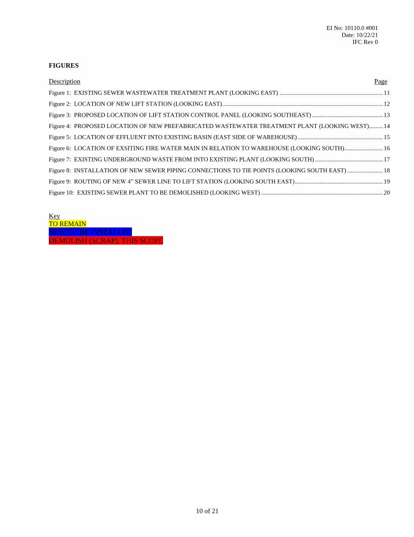
Figure 4: PROPOSED LOCATION OF NEW PREFABRICATED WASTEWATER TREATMENT PLANT
(LOOKING WEST)
NEW WASTEWATER TREATMENT
PLANT SHALL BE LOCATED NEAR
THE NORTH EAST CORNER OF THE
WAREHOUSE. REFER TO
CONTRACT DOCUMENTS FOR
EXACT LOCATION AND SIZE OF
CONCRETE FOUNDATION AND
LAYOUT OF PLANT CHAMBERS,
PANELS, BLOWERS, ETC.
CONTRACTOR SHALL TAKE
CARE TO PROTECT EXISTING
UNDERGROUND GAS LINE
DURING INSTALLATION OF
NEW FOUNDATION &
TREATMENT PLANT. VERIFY
ROUTING OF PIPING PRIOR TO
ANY EXCAVATION.
CONTRACTOR SHALL TAKE
CARE TO PROTECT
EXISTING UNDERGROUND
12” FIRE MAIN AND 4”
EFFLUENT DRAIN. VERIFY
ROUTING OF PIPING PRIOR
TO ANY EXCAVATION.

EI No: 10110.0 #001
Date: 10/22/21
IFC Rev 0
15 of 21
Figure 5: LOCATION OF EFFLUENT INTO EXISTING BASIN (EAST SIDE OF WAREHOUSE)
CONTRACTOR SHALL TAKE CARE TO
PROTECT EXISTING UNDERGROUND 4”
EFFLUENT DRAIN FROM EXISTING
SEWER TREATMENT PLANT TO
EXISTING CULVERT. SYSTEM TO
REMAIN IN OPERATION DURING
CONSTRUCTION/INSTALLATION.
VERIFY ROUTING OF PIPING PRIOR TO
ANY EXCAVATION.
NEW EFFLUENT DRAIN LINE FROM
WASTEWATER TREATMENT PLANT
SHALL DRAIN INTO SAME
CULVERT.

EI No: 10110.0 #001
Date: 10/22/21
IFC Rev 0
16 of 21
Figure 6: LOCATION OF EXSITING FIRE WATER MAIN IN RELATION TO WAREHOUSE (LOOKING
SOUTH)
EXISTING UNDERGROUND 12”
FIRE MAIN. VERIFY ROUTING OF
PIPING PRIOR TO ANY
EXCAVATION.
EI No: 10110.0 #001
Date: 10/22/21
IFC Rev 0
17 of 21
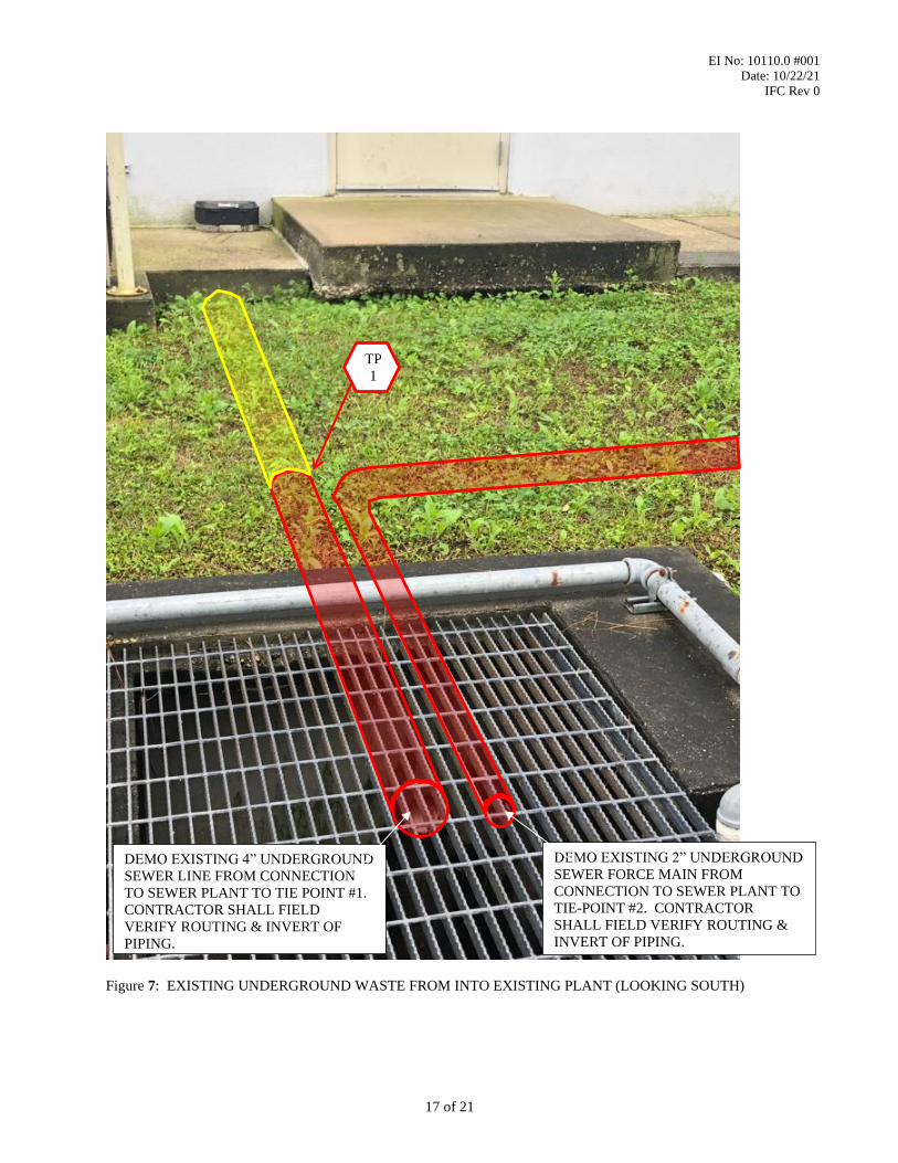
Figure 7: EXISTING UNDERGROUND WASTE FROM INTO EXISTING PLANT (LOOKING SOUTH)
TP
1
DEMO EXISTING 4” UNDERGROUND
SEWER LINE FROM CONNECTION
TO SEWER PLANT TO TIE POINT #1.
CONTRACTOR SHALL FIELD
VERIFY ROUTING & INVERT OF
PIPING.
DEMO EXISTING 2” UNDERGROUND
SEWER FORCE MAIN FROM
CONNECTION TO SEWER PLANT TO
TIE-POINT #2. CONTRACTOR
SHALL FIELD VERIFY ROUTING &
INVERT OF PIPING.
EI No: 10110.0 #001
Date: 10/22/21
IFC Rev 0
18 of 21
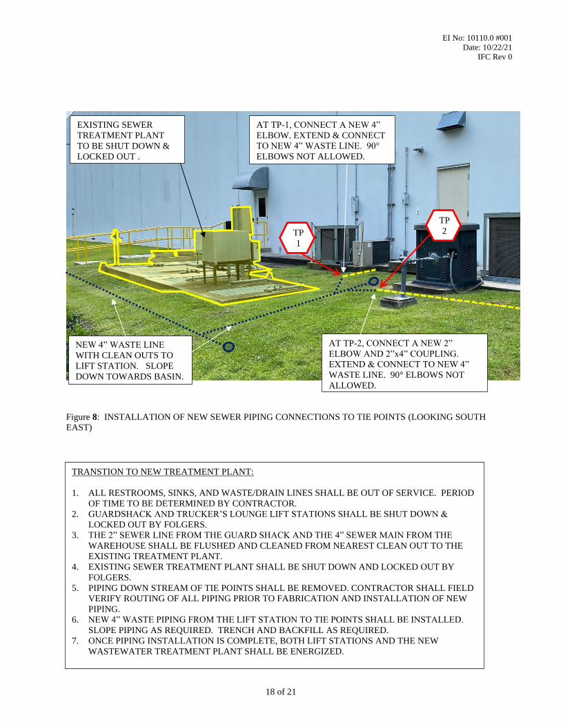
Figure 8: INSTALLATION OF NEW SEWER PIPING CONNECTIONS TO TIE POINTS (LOOKING SOUTH
EAST)
TP
1
AT TP-1, CONNECT A NEW 4”
ELBOW. EXTEND & CONNECT
TO NEW 4” WASTE LINE. 90°
ELBOWS NOT ALLOWED.
AT TP-2, CONNECT A NEW 2”
ELBOW AND 2”x4” COUPLING.
EXTEND & CONNECT TO NEW 4”
WASTE LINE. 90° ELBOWS NOT
ALLOWED.
EXISTING SEWER
TREATMENT PLANT
TO BE SHUT DOWN &
LOCKED OUT .
TP
2
NEW 4” WASTE LINE
WITH CLEAN OUTS TO
LIFT STATION. SLOPE
DOWN TOWARDS BASIN.
TRANSTION TO NEW TREATMENT PLANT:
1. ALL RESTROOMS, SINKS, AND WASTE/DRAIN LINES SHALL BE OUT OF SERVICE. PERIOD
OF TIME TO BE DETERMINED BY CONTRACTOR.
2. GUARDSHACK AND TRUCKER’S LOUNGE LIFT STATIONS SHALL BE SHUT DOWN &
LOCKED OUT BY FOLGERS.
3. THE 2” SEWER LINE FROM THE GUARD SHACK AND THE 4” SEWER MAIN FROM THE
WAREHOUSE SHALL BE FLUSHED AND CLEANED FROM NEAREST CLEAN OUT TO THE
EXISTING TREATMENT PLANT.
4. EXISTING SEWER TREATMENT PLANT SHALL BE SHUT DOWN AND LOCKED OUT BY
FOLGERS.
5. PIPING DOWN STREAM OF TIE POINTS SHALL BE REMOVED. CONTRACTOR SHALL FIELD
VERIFY ROUTING OF ALL PIPING PRIOR TO FABRICATION AND INSTALLATION OF NEW
PIPING.
6. NEW 4” WASTE PIPING FROM THE LIFT STATION TO TIE POINTS SHALL BE INSTALLED.
SLOPE PIPING AS REQUIRED. TRENCH AND BACKFILL AS REQUIRED.
7. ONCE PIPING INSTALLATION IS COMPLETE, BOTH LIFT STATIONS AND THE NEW
WASTEWATER TREATMENT PLANT SHALL BE ENERGIZED.

EI No: 10110.0 #001
Date: 10/22/21
IFC Rev 0
19 of 21
Figure 9: ROUTING OF NEW 4” SEWER LINE TO LIFT STATION (LOOKING SOUTH EAST)
NEW 4” WASTE LINE TO LIFT
STATION. SLOPE DOWN
TOWARDS BASIN. TUNNEL
UNDER WALKWAY.

EI No: 10110.0 #001
Date: 10/22/21
IFC Rev 0
20 of 21
Figure 10: EXISTING SEWER PLANT TO BE DEMOLISHED (LOOKING WEST)
ONCE NEW WASTEWATER TREATMENT PLANT IS IN OPERATION, THE EXISTING
TREATMENT PLANT SHALL BE DEMOLISHED AND REMOVED. CONTRACTOR
SHALL COORDINATE REMOVAL OF EXISTING WASTE, CLEAN AND SANIZTE
BASIN, BREAK DOWN AND RECYCLE CONCRETE AND REMOVE DEBRIS FROM SITE.
BACKFILL AND COMPACT TO MATCH EXISTING IN ACCORDANCE WITH THE
PROJECT SPECIFICATIONS.

EI No: 10110.0 #001
Date: 10/22/21
IFC Rev 0
21 of 21
V. ATTACHMENTS
1. Mechanical/Structural Drawing Package
a. Release Register
b. Piping Tie-In List
c. Structural Drawings
d. Mechanical/Piping Drawings
e. Schedule of Drawings and Other Document Requirements (SDODR)
f. Request For Information (RFI) Form
2. Folgers-provided Equipment Drawing & Data Package [see Vendor Data Release Register for full list of
documents]
3. Folgers Engineering Standards and Specifications [see Section II.3 above for full list of documents in this
attachment]
VI. SIGNATURES
Originator:
Heidi R. Gremillion
Plant Contact:
Linda Wacker
Honeycutt, Valerie
Stamp

JOB NO: 10110 PROJECT TITLE : LACOMBE WASTEWATER TREATMENT PLANT REPLACEMENT REV: 0
CLIENT: FOLGERS DISCIPLINE : MECHANICAL/CIVIL/PROCESS DATE: 10/20/2021
REV. REV. REV. REV.
DATE DATE DATE DATE
PLAN AND ELEVATION DRAWINGS
X PG-3608510LACOMBE DISTRIBUTION CENTER WASTEWATER TREATMENT UNIT OVERALL PLAN
010/22/2021
X PG-3608511LACOMBE DISTRIBUTION CENTER WASTEWATER TREATMENT UNIT PLANS, SECTIONS AND DETAILS
010/22/2021
X PG-3608811LACOMBE DISTRIBUTION CENTER WASTEWATER TREATMENT UNIT GENERAL ARRANGEMENT
010/22/2021
X PG-3608812LACOMBE DISTRIBUTION CENTER WASTEWATER TREATMENT UNIT LIFT STATION & PIPING PLAN
010/22/2021
X PG-3608813LACOMBE DISTRIBUTION CENTER WASTEWATER TREATMENT UNIT WASTEWATER PLANT & PIPING PLAN
010/22/2021
X PG-3608814 LACOMBE DISTRIBUTION CENTER WASTEWATER TREATMENT UNIT DETAILS0
10/22/2021
TITLESEQ.ISSUED THIS
TRANSMITTALCLIENT DWG. NO.
EI 10110.0#001 LACOMBE WASTEWATER TREATMENT PLANT REPLACEMENT - INSTALLATION RELEASE REGISTER
Page 1 of 1

EI NO.: 10110.0#001 PROJECT TITLE: FILE NAME: TIE-IN LIST
CLIENT: FOLGERS DISCIPLINE: REV / DATE: REV 0 10/22/21
TIE-INNUMBER
LINE NUMBERTYPE OF
TIE-INFROM
EQUIPMENT/HEADERTO EQUIPMENT/HEADER FLOWSHEET NUMBER
INSTALLATIONDRAWING NO.
1 PVC WELD/GLUE 4" PVC LIFT STATION PG-3608812EI
FIGURE #8
2 PVC WELD/GLUE 2" PVC LIFT STATION PG-3608812EI
FIGURE #8
LACOMBE WASTEWATER TREATMENT PLANT
MECHANICAL / PIPING DESIGN
PIPING TIE-IN LIST
1 of 1

PAGE 1 OF 2
SCHEDULE OF DRAWING &OTHER DOCUMENT REQUIREMENTS
EQUIPMENT DESCRIPTION LACOMBE WASTEWATER TREATMENT PLANT REPLACEMENT INQUIRY/P.O. NO.
SPEC/ITEM NO. REV./DATE 0 / October 22, 2021
I COPIES QUANTITIES REQUIRED AFTER PURCHASE I COPIES QUANTITIES REQUIRED AFTER PURCHASE
T REQ'D FOR REVIEW FINAL T REQ'D FOR REVIEW FINAL
E DOCUMENT/DATA WITH ELECTRONIC DATE ELECTRONIC DATE E DOCUMENT/DATA WITH ELECTRONIC DATE ELECTRONIC DATE
M QUOTE FILE REPRO REQ'D FILE REPRO REQ'D M QUOTE FILE REPRO REQ'D FILE REPRO REQ'D
A DIMENSIONED OUTLINE AND/OR O DESCRIPTION OF SUPPLIER'S
GENERAL ARRANGEMENT DRAWINGS 1 1 1 A 1 1 A QUALITY CONTROL PLAN/METHODS 1 1 1 A 1 1 A
B ANCHOR BOLT LAYOUTS OR P INSPECTION/TEST PROCEDURE
FOUNDATION PLANS 1 1 1 A 1 1 A 1 1 1 A 1 1 A
C FABRICATION AND CONSTRUCTION Q NDE PROCEDURES
SCHEDULE 1 1 1 A 1 1 A 1 1 A 1 1 A
D MATERIAL CERTIFICATES R INSPECTION/TEST DATA
1 1 A 1 1 F 1 1 D
E PARTS LIST AND CROSS S C 1 COMPLIANCE
SECTIONAL DRAWINGS E 1 1 A 1 1 F
F RECOMMENDED SPARE PARTS LIST R 2 PERSONNEL
WITH PRICES T 1 1 A 1 1 F
G INSTALLATION, OPERATION, AND I 3 EQUIPMENT
MAINTENANCE MANUALS 1 1 A 1 1 A F
H FABRICATION AND/OR SHOP I 4 TEST DATA
DETAIL DRAWINGS 1 1 1 A 1 1 B C 1 1 D
I ASSEMBLY AND/OR ERECTION A 5 MILL TEST
DRAWINGS 1 1 A 1 1 B T
J WELDERS QUALIFICATIONS E 6 OTHER
1 1 1 A 1 1 B S
K WELDING PROCEDURES T HYDROSTATIC TEST CHARTS
(WPS/PQR) 1 1 1 A 1 1 B 1 1 1 A 1 1 A
L AS-BUILT REDLINES U RECEIVING INSTRUCTIONS
1 1 E (INSPECTION & TEST) 1 A 1 1 B
M CALCULATIONS V HANDLING-LIFTING
INSTRUCTIONS 1 1 A 1 1 B
N PERSONNEL QUALIFICATION CERT. W B.O.M, PACKING LIST, SHIPPING LISTFOR NON-DESTRUCTIVE EXAM. 1 1 1 A 1 1 B 1 1 F
EI 10110.0#001

PAGE 2 OF 2
SCHEDULE OF DRAWING &OTHER DOCUMENT REQUIREMENTS
EQUIPMENT DESCRIPTION LACOMBE WASTEWATER TREATMENT PLANT REPLACEMENT INQUIRY/P.O. NO.
SPEC/ITEM NO. REV./DATE 0 / October 22, 2021
I COPIES QUANTITIES REQUIRED AFTER PURCHASE I COPIES QUANTITIES REQUIRED AFTER PURCHASE
T REQ'D FOR REVIEW FINAL T REQ'D FOR REVIEW FINAL
E DOCUMENT/DATA WITH ELECTRONIC DATE ELECTRONIC DATE E DOCUMENT/DATA WITH ELECTRONIC DATE ELECTRONIC DATE
M QUOTE FILE REPRO REQ'D FILE REPRO REQ'D M QUOTE FILE REPRO REQ'D FILE REPRO REQ'D
X CUTSHEETS OF CONTRACTOR-
SUPPLIED COMPONENTS 1 1 1 A 1 1 B
Y
Z
NOTE: ALL DOCUMENTS AND DATA SUBMITTALS MUST BE REFERENCED TO THE INQUIRY OR P.O. NO., SPEC ITEM NO., AND ITEM DESIGNATOR. SEE PREVIOUS PAGE FOR ADDITIONAL REQUIREMENTS.
REMARKS:
A - 2 WEEKS after issue of Purchase Order.
B - 4 WEEKS after issue of Purchase Order.
C - 6 WEEKS after issue of Purchase Order.
D - 2 WEEKS after test
E - PRIOR TO OWNER'S ACCEPTANCE OF EQUIPMENT
F - WITH SHIPMENT
EI 10110.0#001

Rev # By Company Date
Date:
Date:
Date:Responder Company:
Change Order #:
Recipient Company:Disposition:
Response By:
Received By:
Originator:
Supporting Documents or List of Attachments:
Vendor/Contractor:
Vendor/Contractor Request:
Vendor/Contractor Proposed Solution:
To:
Cc:
LACOMBE WASTEWATER TREATMENT PLANT REPLACEMENT10110
Subject:RFI #: Origination Date:
Vendor Project #:
REQUEST FOR INFORMATION FORM (RFI)
Client Project #:Project Name:

JOB NO: 10110 PROJECT TITLE : LACOMBE WASTEWATER TREATMENT PLANT REPLACEMENT REV: 0 IFC
CLIENT: FOLGERS DISCIPLINE : MECHANICAL/PROCESS DATE: 10/22/2021
REV. REV. REV. REV.
DATE DATE DATE DATE
FOR REFERENCE ONLY
FOR REFERENCE
#235-1195 N/A 10,000 GPD PREFABRICATED WASTEWATER TREATMENT PLANT N/A
FOR REFERENCE
NA/ DUPLEX GRINDER LIFT STATION & CONTROL PANEL N/A
TITLEISSUEDCLIENT TAG
NUMBERVENDOR DWG. NO.
E.I. 10110.0#001 VENDOR DATA RELEASE REGISTER
Page 1 of 1


Field Installation Instructions
GENERAL CONTRACTOR’S FIELD SERVICES
The General Contractor shall perform the actual installation of the package wastewater treatment
system. This shall be an above grade installation.
General Contractor’s responsibilities regarding the installation as well as a brief description of the
General Contractor’s field crews area of responsibilities:
•An adequate access road to the plant site shall be provided to enable the system to be off loaded
at the project site.
•Provide a concrete foundation pad for the wastewater treatment system. The foundation pad
should be swept free of debris prior to setting the wastewater treatment system.
•The wastewater treatment system shall be delivered to the project site in one major section. Due
to shipping restrictions, the ancillary equipment has been removed from the tankage. The
contractor shall use the crane to set the ancillary equipment on top of the system per the contract
drawings.
DXP ENTERPRISES, INC
Page # 1
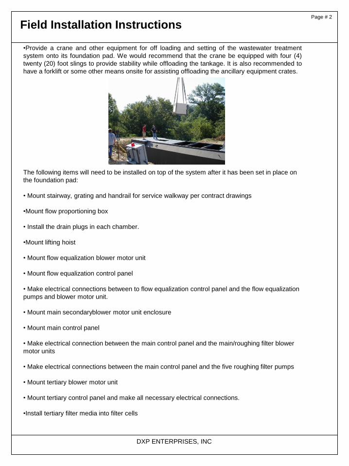
Field Installation Instructions
•Provide a crane and other equipment for off loading and setting of the wastewater treatment
system onto its foundation pad. We would recommend that the crane be equipped with four (4)
twenty (20) foot slings to provide stability while offloading the tankage. It is also recommended to
have a forklift or some other means onsite for assisting offloading the ancillary equipment crates.
The following items will need to be installed on top of the system after it has been set in place on
the foundation pad:
• Mount stairway, grating and handrail for service walkway per contract drawings
•Mount flow proportioning box
• Install the drain plugs in each chamber.
•Mount lifting hoist
• Mount flow equalization blower motor unit
• Mount flow equalization control panel
• Make electrical connections between to flow equalization control panel and the flow equalization
pumps and blower motor unit.
• Mount main secondaryblower motor unit enclosure
• Mount main control panel
• Make electrical connection between the main control panel and the main/roughing filter blower
motor units
• Make electrical connections between the main control panel and the five roughing filter pumps
• Mount tertiary blower motor unit
• Mount tertiary control panel and make all necessary electrical connections.
•Install tertiary filter media into filter cells
DXP ENTERPRISES, INC
Page # 2

Field Installation Instructions
• Bring electrical power to each of the connection points
•All areas requiring touch up painting shall be painted by the General Contractor’s field crew.
• All field piping external of the wastewater treatment system shall be installed by the contractor
•Once set into position the system is to be filled with water prior to start-up and after the drain
plugs have been installed.
Page # 3
DXP ENTERPRISES, INC
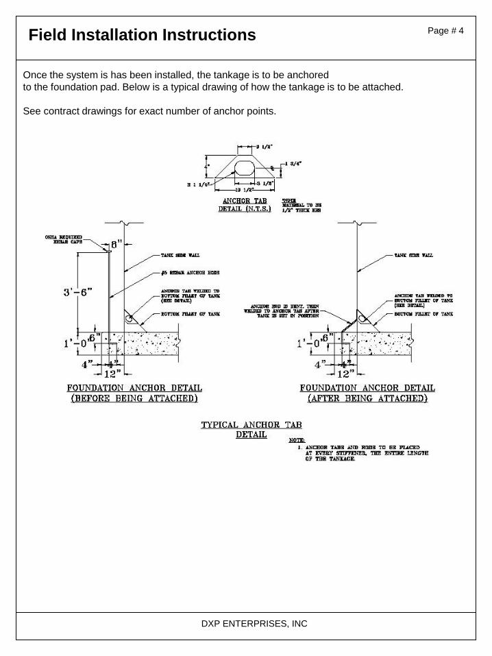
Field Installation Instructions
Once the system is has been installed, the tankage is to be anchored
to the foundation pad. Below is a typical drawing of how the tankage is to be attached.
See contract drawings for exact number of anchor points.
Page # 4
DXP ENTERPRISES, INC
Specifications: inches(mm)
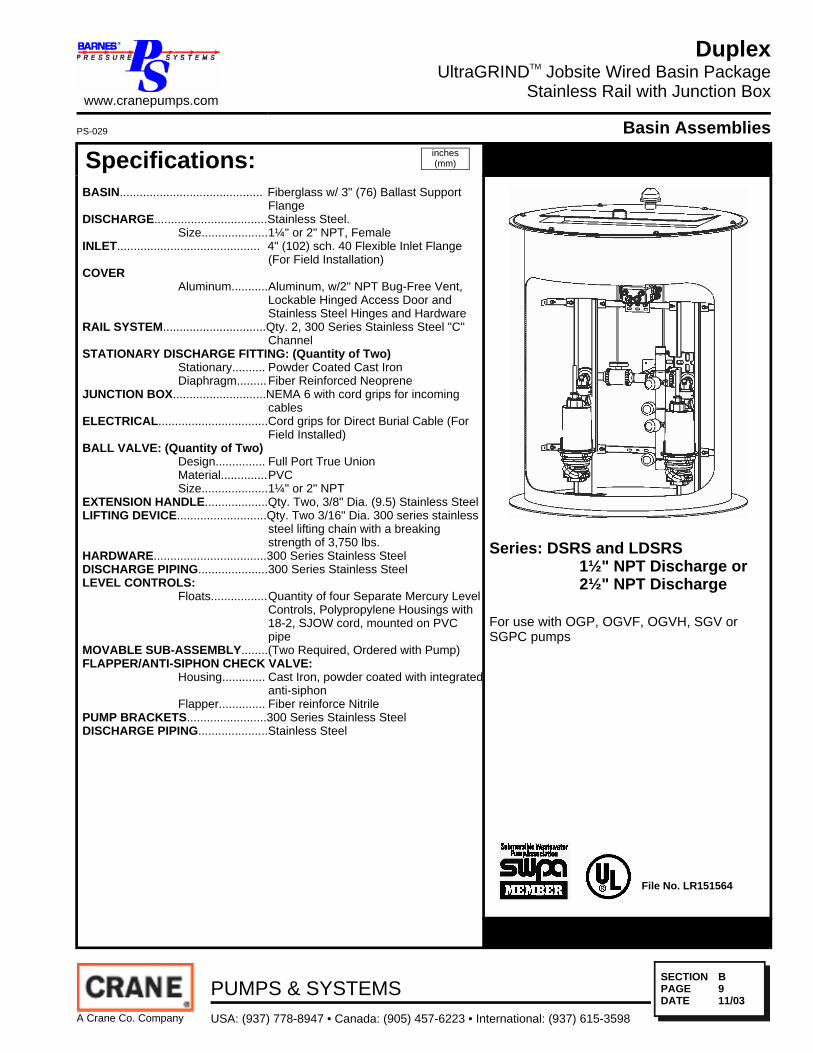
BASIN........................................... Fiberglass w/ 3" (76) Ballast SupportFlange
DISCHARGE..................................Stainless Steel.Size....................1¼" or 2" NPT, Female
INLET........................................... 4" (102) sch. 40 Flexible Inlet Flange(For Field Installation)
COVERAluminum...........Aluminum, w/2" NPT Bug-Free Vent,
Lockable Hinged Access Door andStainless Steel Hinges and Hardware
RAIL SYSTEM...............................Qty. 2, 300 Series Stainless Steel "C"Channel
STATIONARY DISCHARGE FITTING: (Quantity of Two)Stationary.......... Powder Coated Cast IronDiaphragm.........Fiber Reinforced Neoprene
JUNCTION BOX............................NEMA 6 with cord grips for incomingcables
ELECTRICAL.................................Cord grips for Direct Burial Cable (ForField Installed)
BALL VALVE: (Quantity of Two)Design............... Full Port True UnionMaterial..............PVCSize....................1¼" or 2" NPT
EXTENSION HANDLE...................Qty. Two, 3/8" Dia. (9.5) Stainless SteelLIFTING DEVICE...........................Qty. Two 3/16" Dia. 300 series stainless
steel lifting chain with a breakingstrength of 3,750 lbs.
HARDWARE..................................300 Series Stainless SteelDISCHARGE PIPING.....................300 Series Stainless SteelLEVEL CONTROLS:
Floats.................Quantity of four Separate Mercury LevelControls, Polypropylene Housings with18-2, SJOW cord, mounted on PVCpipe
MOVABLE SUB-ASSEMBLY........(Two Required, Ordered with Pump)FLAPPER/ANTI-SIPHON CHECK VALVE:
Housing............. Cast Iron, powder coated with integratedanti-siphon
Flapper.............. Fiber reinforce NitrilePUMP BRACKETS........................300 Series Stainless SteelDISCHARGE PIPING.....................Stainless Steel
Series: DSRS and LDSRS1½" NPT Discharge or2½" NPT Discharge
For use with OGP, OGVF, OGVH, SGV orSGPC pumps
File No. LR151564
www.cranepumps.com
DuplexUltraGRINDTM Jobsite Wired Basin Package
Stainless Rail with Junction Box
PS-029 Basin Assemblies
A Crane Co. Company
PUMPS & SYSTEMSUSA: (937) 778-8947 • Canada: (905) 457-6223 • International: (937) 615-3598
SECTIONPAGEDATE
B911/03

Specifications:DISCHARGE..................................1¼" NPT, Vertical, Bolt-on FlangeLIQUID TEMPERATURE...............160°F (71°C) IntermittentVOLUTE.........................................Cast Iron ASTM A-48, Class 30MOTOR HOUSING........................Cast Iron ASTM A-48, Class 30SEAL PLATE.................................Cast Iron ASTM A-48, Class 30IMPELLER:
Design............... 12 Vane,Vortex, With Pump Out VanesOn Back Side. Dynamically Balanced,ISO G6.3.
Material..............85-5-5-5 BronzeSHREDDING RING........................Hardened 440C Stainless Steel
Rockwell® C-55.CUTTER.........................................Hardened 440CStainless Steel,
Rockwell® C-55.SHAFT........................................... 416 Stainless SteelSQUARE RINGS............................Buna-NHARDWARE..................................300 Series Stainless SteelPAINT........................................... Air Dry Enamel.SEAL:
Design............... Tandem Mechanical, Oil FilledReservoir.
Material..............Rotating Faces - CarbonStationary Faces - CeramicElastomer - Buna-NHardware -300 Series Stainless
CORD ENTRY................................30 ft. (9.1m) Std. Cord. Custom MoldedQuick Connect, for Sealing and StrainRelief
CORD........................................... CSA/UL Approved 12/4 Type SOWUPPER BEARING:
Design............... Single Row, Ball, Oil LubricatedLoad...................Radial
INTERMEDIATE BEARING:Design............... Single Row, Ball, Oil LubricatedLoad...................Radial & Thrust
LOWER BEARING:Design............... Sleeve, Oil Lubrication:Load...................Radial
MOTOR:Design............... NEMA L-Single Phase, (SGVF2022L,
SGVH2022L, SGVF2002L orSGVH2002L includes overloadprotection in the motor).
Insulation........... Class F.SINGLE PHASE.............................Capacitor Start/Capacitor Run. Includes
overload protection in the motor.Requires Barnes® Starter or ControlPanel which Includes Capacitors, orCapacitor pack.
Series: SGVF2HP, 3450RPM, 60HzHigh-Flow
CSA 108 - File No. LR16567UL 778
DESCRIPTION:THE GRINDER PUMP IS DESIGNED TOREDUCE DOMESTIC, COMMERCIAL,INSTITUTIONAL AND LIGHT INDUSTRIALSEWAGE TO A FINELY GROUND SLURRY.
www.cranepumps.com
Model SGVFRecessed Vortex
PS-001 Submersible Grinder Pumps
A Crane Co. Company
PUMPS & SYSTEMSUSA: (937) 778-8947 • Canada: (905) 457-6223 • International: (937) 615-3598
SECTIONPAGEDATE
A175/05

MODEL NO PART NO HP VOLT PH/Hz RPM(Nom)
NEMASTARTCODE
FULLLOADAMPS
LOCKEDROTORAMPS
CORDSIZE
CORDTYPE
CORD O.D.± .02 (.5) in
(mm)HIGH-FLOWSGVF2022L 110609ANC 2 240 1 / 60 3450 F 15.0 53.8 12/4 SOW .67 (17)
Optional - Moisture and Temperature sensor cord for all models is 18/5 SOW, 0.49 (12.4mm) ± .02 (.51mm) O.D., replaces Temperature sensorcord.
IMPORTANT !1.) PUMP MAY BE OPERATED "DRY" FOR EXTENDED PERIODS WITHOUT DAMAGE TO MOTOR AND/OR SEALS.2.) THIS PUMP IS APPROPRIATE FOR THOSE APPLICATIONS SPECIFIED AS CLASS I DIVISION II HAZARDOUS LOCATIONS.3.) THIS PUMP IS NOT APPROPRIATE FOR THOSE APPLICATIONS SPECIFIED AS CLASS I DIVISION I HAZARDOUS LOCATIONS.4.) INSTALLATIONS SUCH AS DECORATIVE FOUNTAINS OR WATER FEATURES PROVIDED FOR VISUAL ENJOYMENT MUST BE INSTALLED IN
ACCORDANCE WITH THE NATIONAL ELECTRIC CODE ANSI/NFPA 70 AND/OR THE AUTHORITY HAVING JURISDICTION. THIS PUMP IS NOTINTENDED FOR USE IN SWIMMING POOLS, RECREATIONAL WATER PARKS, OR INSTALLATIONS IN WHICH HUMAN CONTACT WITH PUMPEDMEDIA IS A COMMON OCCURRENCE.
inches(mm)
Models SGVFRecessed Vortex
www.cranepumps.com
Submersible Grinder Pumps PS-002
A Crane Co. Company
PUMPS & SYSTEMSUSA: (937) 778-8947 • Canada: (905) 457-6223 • International: (937) 615-3598
SECTIONPAGEDATE
A183/07
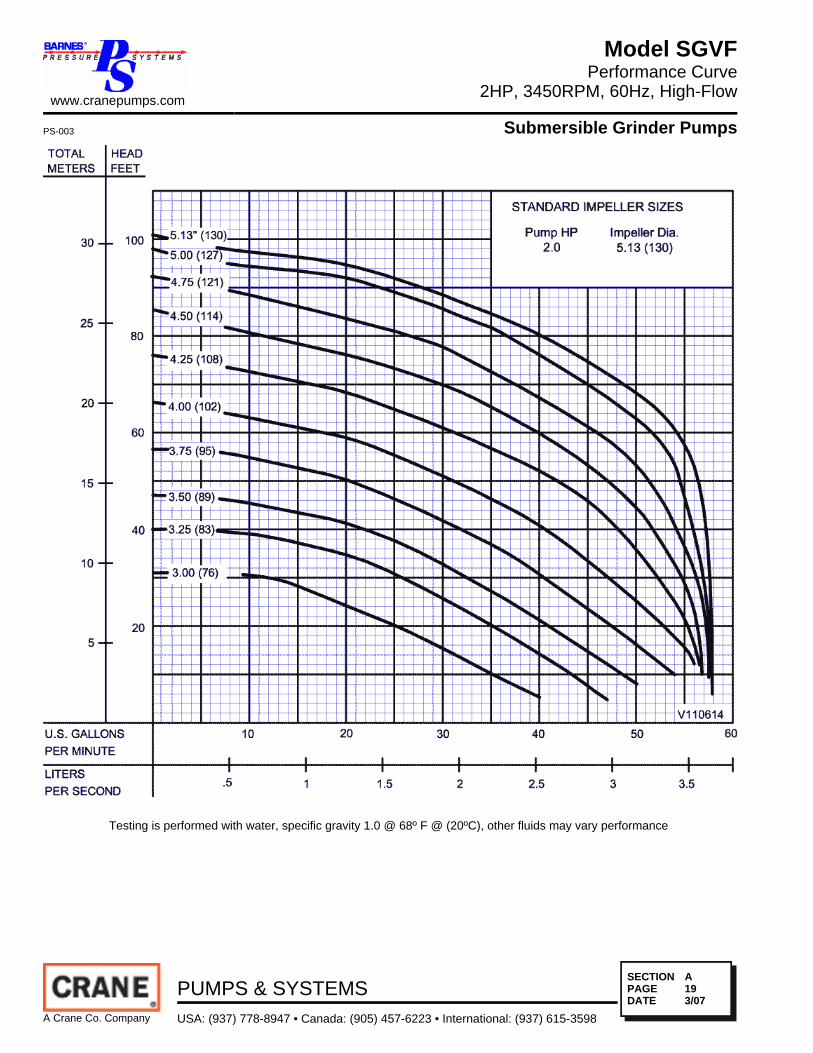
Testing is performed with water, specific gravity 1.0 @ 68º F @ (20ºC), other fluids may vary performance
www.cranepumps.com
Model SGVFPerformance Curve
2HP, 3450RPM, 60Hz, High-Flow
PS-003 Submersible Grinder Pumps
A Crane Co. Company
PUMPS & SYSTEMSUSA: (937) 778-8947 • Canada: (905) 457-6223 • International: (937) 615-3598
SECTIONPAGEDATE
A193/07
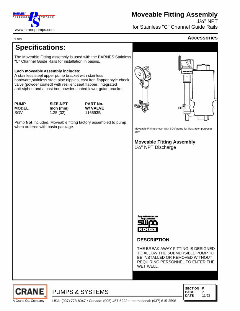
Specifications:The Moveable Fitting assembly is used with the BARNES Stainless"C" Channel Guide Rails for installation in basins.
Each moveable assembly includes:A stainless steel upper pump bracket with stainlesshardware,stainless steel pipe nipples, cast iron flapper style checkvalve (powder coated) with resilient seat flapper, integratedanti-siphon and a cast iron powder coated lower guide bracket.
PUMPMODEL
SIZE-NPTInch (mm)
PART No.W/ VALVE
SGV 1.25 (32) 116593B
Pump Not Included, Moveable fitting factory assembled to pumpwhen ordered with basin package. Moveable Fitting shown with SGV pump for illustration purposes
only
Moveable Fitting Assembly1¼" NPT Discharge
DESCRIPTION
THE BREAK AWAY FITTING IS DESIGNEDTO ALLOW THE SUBMERSIBLE PUMP TOBE INSTALLED OR REMOVED WITHOUTREQUIRING PERSONNEL TO ENTER THEWET WELL.
www.cranepumps.com
Moveable Fitting Assembly1¼" NPT
for Stainless "C" Channel Guide Rails
PS-050 Accessories
A Crane Co. Company
PUMPS & SYSTEMSUSA: (937) 778-8947 • Canada: (905) 457-6223 • International: (937) 615-3598
SECTIONPAGEDATE
F711/03

Specifications:HOUSING ......................... ASTM Class 30 Cast Iron, Powder
CoatedFLAPPER ......................... Nitrile, Nylon ReinforcedTEMPERATURE ............... 160°F (71°C) continuousPRESSURE RATING ........ 150 Lbs./Sq. In.(10.6 kgs/sq. cm)
FEATURES:• Works in BARNES standard "C" Channel Rail
• Full port check with minimum head loss
• 18" static head requirement for minimum seat
• Valve includes integrated anti-siphon
• 300 series stainless steel hardware
• Integrated upper moveable fitting
• Resilient seat flapper
• Quiet operation
• No maintenance
• Vertical position mounting
APPLICATIONS:
Waste water or residential sewage, liquid manure, etc.
Cast Iron Flap Style CheckValve/Upper Moveable Fitting1¼" NPT P/N: 112354
www.cranepumps.com
Flap Style Check Valve/Upper MoveableFor use with "C" Channel Rails
1¼" NPT
PS-089 Accessories
A Crane Co. Company
PUMPS & SYSTEMSUSA: (937) 778-8947 • Canada: (905) 457-6223 • International: (937) 615-3598
SECTIONPAGEDATE
F911/03
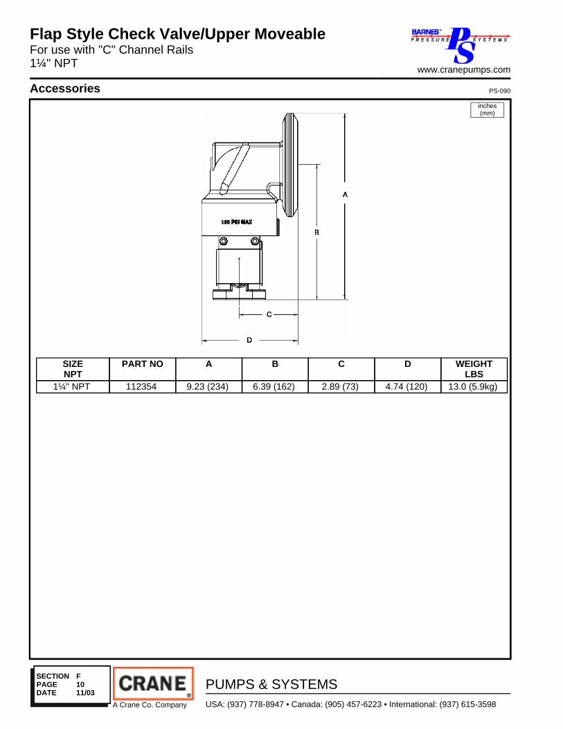
SIZENPT
PART NO A B C D WEIGHTLBS
1¼" NPT 112354 9.23 (234) 6.39 (162) 2.89 (73) 4.74 (120) 13.0 (5.9kg)
inches(mm)
Flap Style Check Valve/Upper MoveableFor use with "C" Channel Rails1¼" NPT
www.cranepumps.com
Accessories PS-090
A Crane Co. Company
PUMPS & SYSTEMSUSA: (937) 778-8947 • Canada: (905) 457-6223 • International: (937) 615-3598
SECTIONPAGEDATE
F1011/03
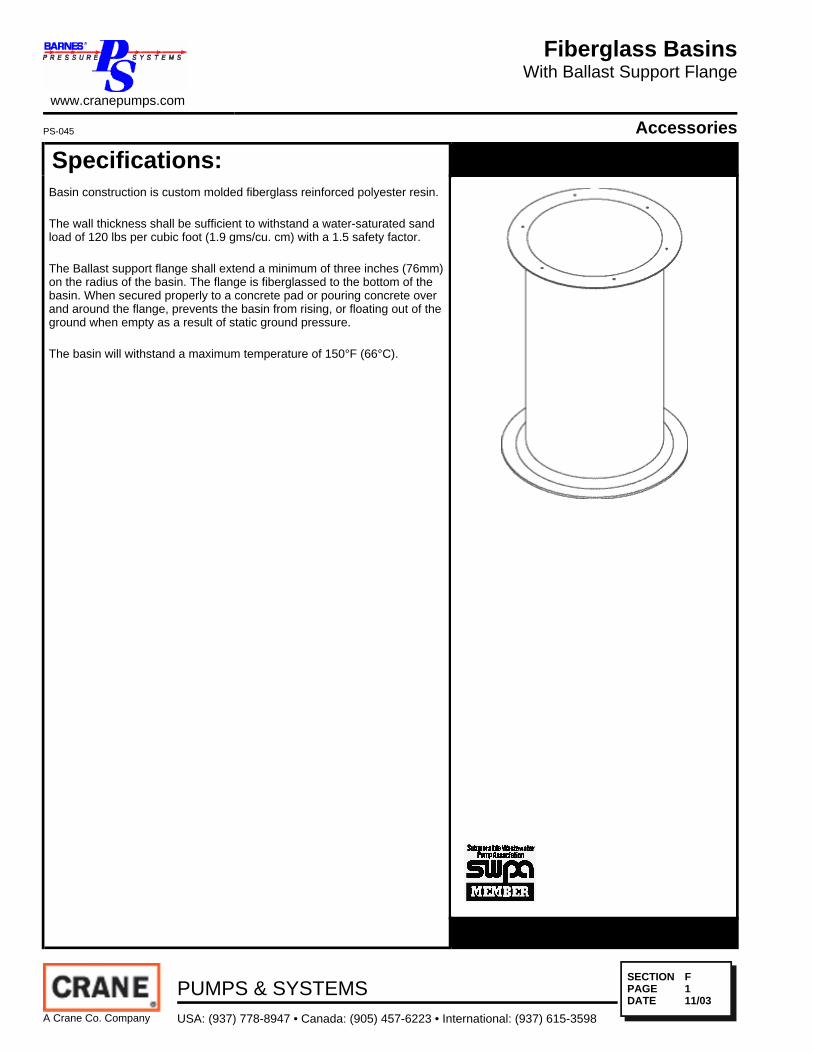
Specifications:Basin construction is custom molded fiberglass reinforced polyester resin.
The wall thickness shall be sufficient to withstand a water-saturated sandload of 120 lbs per cubic foot (1.9 gms/cu. cm) with a 1.5 safety factor.
The Ballast support flange shall extend a minimum of three inches (76mm)on the radius of the basin. The flange is fiberglassed to the bottom of thebasin. When secured properly to a concrete pad or pouring concrete overand around the flange, prevents the basin from rising, or floating out of theground when empty as a result of static ground pressure.
The basin will withstand a maximum temperature of 150°F (66°C).
www.cranepumps.com
Fiberglass BasinsWith Ballast Support Flange
PS-045 Accessories
A Crane Co. Company
PUMPS & SYSTEMSUSA: (937) 778-8947 • Canada: (905) 457-6223 • International: (937) 615-3598
SECTIONPAGEDATE
F111/03

Specifications:Basin covers have hinged access door, lifting handle, lockingprovisions, stainless steel hinges and hardware and provisions for2" NPT vent.
Aluminum:
Covers available for basin diameters 36" through 60" (914 through1524mm) and are .25" (6.4mm) thick.
ALL covers have a service rating of 150 lbs/sq. ft. (732kgs/sq.meter) minimum.
For 48" (1219) & 60" (1524) Diameter Basins
Basin CoverAluminum
Basin Covers
www.cranepumps.com
Accessories PS-055
A Crane Co. Company
PUMPS & SYSTEMSUSA: (937) 778-8947 • Canada: (905) 457-6223 • International: (937) 615-3598
SECTIONPAGEDATE
F1811/03
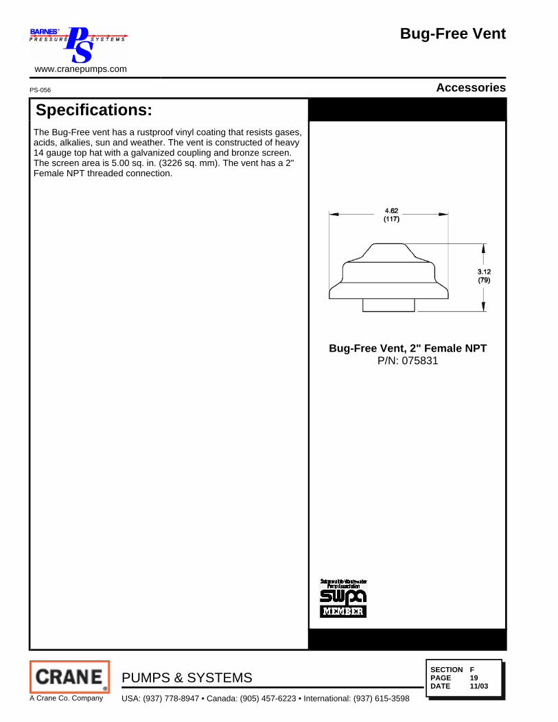
Specifications:The Bug-Free vent has a rustproof vinyl coating that resists gases,acids, alkalies, sun and weather. The vent is constructed of heavy14 gauge top hat with a galvanized coupling and bronze screen.The screen area is 5.00 sq. in. (3226 sq. mm). The vent has a 2"Female NPT threaded connection.
Bug-Free Vent, 2" Female NPTP/N: 075831
www.cranepumps.com
Bug-Free Vent
PS-056 Accessories
A Crane Co. Company
PUMPS & SYSTEMSUSA: (937) 778-8947 • Canada: (905) 457-6223 • International: (937) 615-3598
SECTIONPAGEDATE
F1911/03

Specifications:The "C" channel guide rail assembly is made of 300 seriesstainless steel. The guide rail mounts to the upper and lowerhorizontal brackets attached to the basin wall. The rail also rest onthe bottom of the basin floor. The stainless steel guide rail supportsthe pump the required distance from the basin floor. Guidebrackets (supplied with the Moveable Fitting Assembly) areattached to the pump for positioning of the unit on the guide railduring installationand removal.
The stationary of the hydraulically sealed discharge is powdercoated machined cast iron. The stationary fitting has a fiberrein-forced neoprene diaphragm clamped between the stainlesssteel rail and the stationary pressure vessel. The moveable fitting isheld against the stationary fitting by the construction of thestainless steel rail, aligning the movable fitting to the flexiblediaphragm for proper sealing of the two surfaces.
Each assembly includes:• 300 Series Stainless Steel Guide Rail.
• 300 Series Stainless Steel Upper And Lower Support Brackets.
• Available For Basin Depths 48" to 156" (1.2M to 3.9m)
• 300 Series Stainless Steel Intermediate support Brackets forBasin Depths 144" (3.7m) and Greater.
• Powder Coated Cast Iron Stationary Fitting.
• Fiber Reinforced Neoprene Diaphragm.
Quantity of One (1) each for Simplex and Two (2) for Duplex."C" Channel Guide Rails for1¼" NPT DischargeSimplex or Duplex
"C" Channel Guide RailsFor 1¼" NPT Moveable Fittings
www.cranepumps.com
Accessories PS-051
A Crane Co. Company
PUMPS & SYSTEMSUSA: (937) 778-8947 • Canada: (905) 457-6223 • International: (937) 615-3598
SECTIONPAGEDATE
F811/03

Specifications:The Flexible Pipe fitting is super-tough for weather and corrosionresistance. The fitting has superior vapor and water leakproofsealing ability. Shipped loose for field installation.
P/N: Description076149 4" (102mm) PVC, Sch. 40-80
Flexible Pipe Fittings
Flexible Pipe Fittings
www.cranepumps.com
Accessories PS-046
A Crane Co. Company
PUMPS & SYSTEMSUSA: (937) 778-8947 • Canada: (905) 457-6223 • International: (937) 615-3598
SECTIONPAGEDATE
F211/03

Specifications:Stainless Steel Bolt-On Couplings
P/N Description094801 1½" NPT, Female
Discharge Couplings
Discharge Couplings
www.cranepumps.com
Accessories PS-048
A Crane Co. Company
PUMPS & SYSTEMSUSA: (937) 778-8947 • Canada: (905) 457-6223 • International: (937) 615-3598
SECTIONPAGEDATE
F411/03
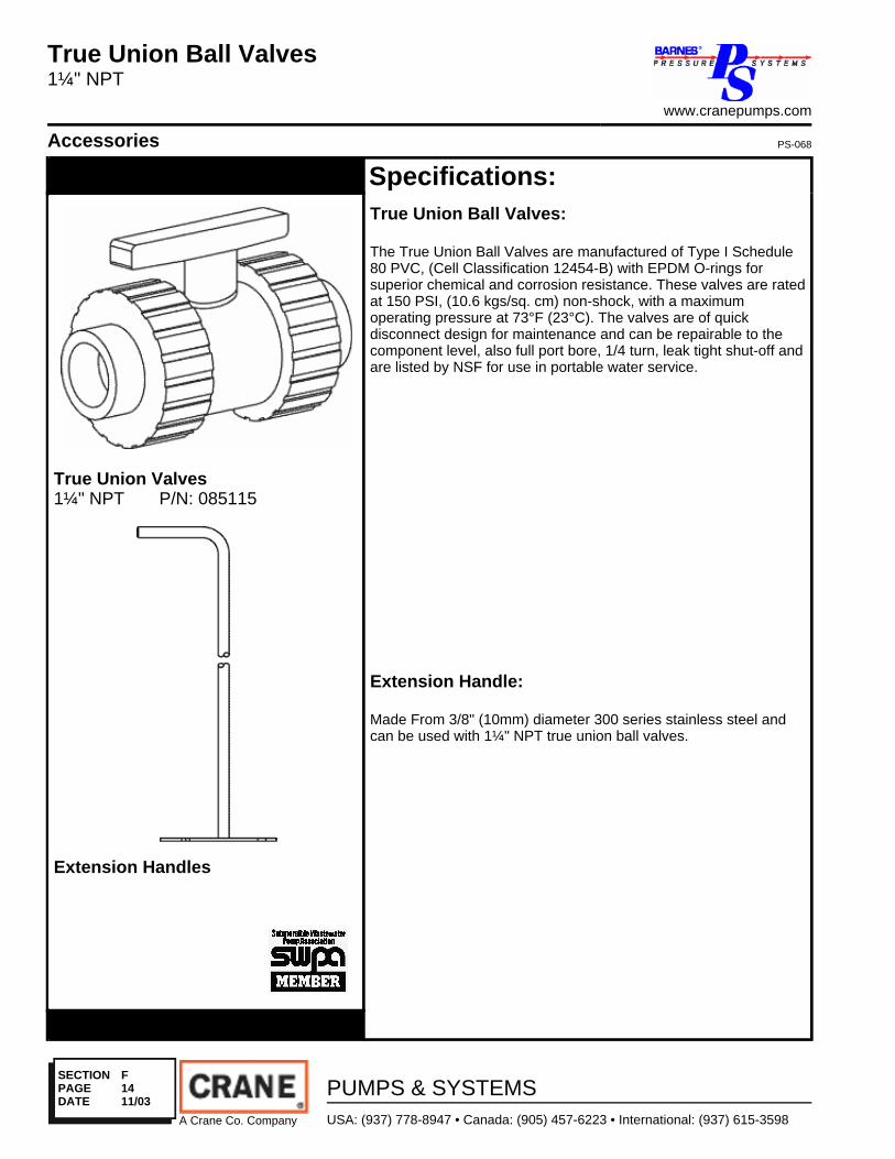
Specifications:True Union Ball Valves:
The True Union Ball Valves are manufactured of Type I Schedule80 PVC, (Cell Classification 12454-B) with EPDM O-rings forsuperior chemical and corrosion resistance. These valves are ratedat 150 PSI, (10.6 kgs/sq. cm) non-shock, with a maximumoperating pressure at 73°F (23°C). The valves are of quickdisconnect design for maintenance and can be repairable to thecomponent level, also full port bore, 1/4 turn, leak tight shut-off andare listed by NSF for use in portable water service.
Extension Handle:
Made From 3/8" (10mm) diameter 300 series stainless steel andcan be used with 1¼" NPT true union ball valves.
True Union Valves1¼" NPT P/N: 085115
Extension Handles
True Union Ball Valves1¼" NPT
www.cranepumps.com
Accessories PS-068
A Crane Co. Company
PUMPS & SYSTEMSUSA: (937) 778-8947 • Canada: (905) 457-6223 • International: (937) 615-3598
SECTIONPAGEDATE
F1411/03

Specifications:The Mercury Level Controls are pilot duty devices which control thefunction of motor load devices, such as contactors, motor starters,and power relays, to automatically cycle a pump or pumps. Theycan also be used for alarm signaling devices.
Qty. 4 floats for Duplex, Pump Off, Pump 1 On, Pump 2 On, Alarm.
Floats Assembly:CORD ...................................... 18/2 SJOW, .29 (7.4mm) DiaMOUNTING ................................ Clip, ABS/Nylon and 300 series
BandclampFLOAT HOUSING ...................... PolypropyleneTEMPERATURE RATING ......... 60° CFLOAT SWITCH ........................ Mercury, Narrow Angle,
HorizontalFLOAT SWITCH RATING: ........ 4.5A @ 115VAC RES
2.25A @ 230VAC RESPOLE ...................................... PVC
Individual Floats AssemblyThe universal mounting bracket allows theIndi-vidual Floats to be located on either side ofthe"C" channel rail for ease of installationaround existing inlets or other obstructions.
Level ControlsIndividual Floats Assembly, TM Duplexfor Barnes "C" Channel Rail System
www.cranepumps.com
Accessories
A Crane Co. Company
PUMPS & SYSTEMSUSA: (937) 778-8947 • Canada: (905) 457-6223 • International: (937) 615-3598
SECTIONPAGEDATE
F2611/03

Specifications:The Duplex Junction Box and all connections have a NEMA 6Rating to protect against occasional submersion and is used inconjunction with U.L. listed water-tight connectors suitable for usewith U.L. listed Direct Burial Cable.
BOX & COVER .......................... Constructed ofImpact-Resistant,Nonconductive, FiberglassReinforced Polyester withStainless Steel Screws
GASKET .................................... NeopreneCHAIN ...................................... Stainless SteelCORD GRIPS ............................. Non-Metallic, Valox with
Neoprene type Grommet.FLOAT SWITCH ........................ Mercury, Narrow Angle,
HorizontalRECOGNITION : ........................ UL Listed 508
Junction BoxNEMA 6, Duplex
File No. E151564
Junction BoxNEMA 6, Duplex
www.cranepumps.com
Accessories PS-063
A Crane Co. Company
PUMPS & SYSTEMSUSA: (937) 778-8947 • Canada: (905) 457-6223 • International: (937) 615-3598
SECTIONPAGEDATE
F2811/03

Specifications:STAINLESS:
.18" Dia. (4.6mm) 300 Series Stainless Steel Lifting Chain, 830lb.(376kg) Working Load. 3750lb. (1701kg) Breaking Strength.
Lifting Chain
Lifting ChainStainless
www.cranepumps.com
Accessories PS-059
A Crane Co. Company
PUMPS & SYSTEMSUSA: (937) 778-8947 • Canada: (905) 457-6223 • International: (937) 615-3598
SECTIONPAGEDATE
F2211/03

Specifications:The Padlock has a brass body with a .25 (6.4mm) diameter by .88inches (22.4mm) long or 2.00 inches (50.8mm) long, brassshackle. All locks are keyed alike.
P/N: 102567 - 0.88" (22.4mm) ShackleP/N: 102568 - 2.00" (50.8mm) Shackle
Brass Padlocks
www.cranepumps.com
PadlocksBrass
PS-071 Accessories
A Crane Co. Company
PUMPS & SYSTEMSUSA: (937) 778-8947 • Canada: (905) 457-6223 • International: (937) 615-3598
SECTIONPAGEDATE
F3111/03

Specifications:R & O SeriesListed by Underwriters Laboratories, duplex pump control panelsprovide reliable grinder pump station operation and potentialmalfunction warning.
STANDARD FEATURES:
• UL 508A Listed• NEMA 4X Fiberglass Enclosure• Padlockable Latch• Pump/Panel Circuit Breaker• IEC Rated Motor Contactor•• Pump Start Pushbutton• Individually Fused Circuits for Alarm and Control Components• 25 Watt High Water Alarm Light with NEMA 4X Lens• Pre-Installed Capacitor Kit (R Panels Only, Capacitor for OGP,
OGVF, OGVH & SGPC Pumps located internally in the pump)• Terminal Strip and Ground Lug for Incoming Connections• Pump Alternator (200 Series Duplex Panels Only)• 90 db alarm horn with NEMA 4X silence pushbutton.
Wall Mounted Series:Stealth-R-200
File No. LR142177
Stealth Control PanelsDuplexWall Mounted Series
www.cranepumps.com
Control Panels PS-040
A Crane Co. Company
PUMPS & SYSTEMSUSA: (937) 778-8947 • Canada: (905) 457-6223 • International: (937) 615-3598
SECTIONPAGEDATE
C210/06


![WELCoMe [brasserieflor.be] · 2020-06-18 · TEA Mighty Leaf Organic Darjeeling Estate 5,1 Green Tea Tropical 5,1 White Orchard 5,1 Organic African Nectar 5,1 Organic Detox Infusion](https://static.fdocuments.us/doc/165x107/5f19b81a83f67f34c925c41c/welcome-2020-06-18-tea-mighty-leaf-organic-darjeeling-estate-51-green-tea.jpg)