
25133-6g0
190
3GPP TS 25.133 V6.16.0 (2006-12) Technical Specification 3rd Generation Partnership Project; Technical Specification Group Radio Access Network; Requirements for support of radio resource management (FDD) (Release 6) The present document has been developed within the 3 rd Generation Partnership Project (3GPP TM ) and may be further elaborated for the purposes of 3GPP. The present document has not been subject to any approval process by the 3GPP Organisational Partners and shall not be implemented. This Specification is provided for future development work within 3GPP only. The Organisational Partners accept no liability for any use of this Specification. Specifications and reports for implementation of the 3GPP TM system should be obtained via the 3GPP Organisational Partners' Publications Offices.
-
Upload
khiem-tran -
Category
Documents
-
view
216 -
download
0
Transcript of 25133-6g0

7/31/2019 25133-6g0
http://slidepdf.com/reader/full/25133-6g0 1/190
3GPP TS 25.133 V6.16.0 (2006-12)Technical Specification
3rd Generation Partnership Project;Technical Specification Group Radio Access Network;
Requirements for support of radio resource management(FDD)
(Release 6)
The present document has been developed within the 3rd Generation Partnership Project (3GPP TM) and may be further elaborated for the purposes of 3GPP.The present document has not been subject to any approval process by the 3GPP Organisational Partners and shall not be implemented.This Specification is provided for future development work within 3GPP only. The Organisational Partners accept no liability for any use of this Specification.Specifications and reports for implementation of the 3GPP TM system should be obtained via the 3GPP Organisational Partners' Publications Offices.

7/31/2019 25133-6g0
http://slidepdf.com/reader/full/25133-6g0 2/190
2Release 6T 3GPP TS 25.133 V6.16.0 (2006-12)
KeywordsUMTS, radio, management
3GPP
Postal address
3GPP support office address650 Route des Lucioles - Sophia Antipolis
Valbonne - FRANCETel.: +33 4 92 94 42 00 Fax: +33 4 93 65 47 16
Internethttp://www.3gpp.org
Copyright Notification
No part may be reproduced except as authorized by written permission.The copyright and the foregoing restriction extend to reproduction in all media.
© 2006, 3GPP Organizational Partners (ARIB, ATIS, CCSA, ETSI, TTA, TTC).All rights reserved.
3GPP

7/31/2019 25133-6g0
http://slidepdf.com/reader/full/25133-6g0 3/190
3Release 6T 3GPP TS 25.133 V6.16.0 (2006-12)
Contents
Foreword ..........................................................................................................................................................12
1 Scope......................................................................................................................................................13 2 References..............................................................................................................................................13
3 Definitions, symbols and abbreviations .................................................................................................14 3.1 Definitions ............................................................... ....................................................................... ................. 14 3.2 Symbols ............................................................... ................................................................ ............................ 14 3.3 Abbreviations....................................... ..................................................................... ....................................... 15 3.4 Test tolerances .............................................................. ................................................................. .................. 16
4 Idle Mode Tasks.....................................................................................................................................16 4.1 Cell Selection..... ..................................................................... ................................................................. ........ 16 4.1.1 Introduction ...................................................................... .................................................................. ........ 16 4.2 Cell Re-selection.................................... ............................................................... ........................................... 16
4.2.1 Introduction ...................................................................... .................................................................. ........ 16 4.2.2 Requirements ................................................................... ................................................................... ....... 16 4.2.2.1 Measurement and evaluation of cell selection criteria S of serving cell............................................... 16 4.2.2.2 Measurements of intra-frequency cells...................... ..................................................................... ...... 17 4.2.2.3 Measurements of inter-frequency FDD cells.......... ............................................................................ .. 17 4.2.2.4 Measurements of inter-frequency TDD cells........................................................................................ 17 4.2.2.5 Measurements of inter-RAT GSM cells ................................................................... ............................ 18 4.2.2.6 Evaluation of cell re-selection criteria ..................................................................... ............................. 18 4.2.2.7 Maximum interruption in paging reception .................................................................. ........................ 18 4.2.2.8 Number of cells in cell lists .................................................................... .............................................. 19 4.2.2.9 Additional requirements for measurement of inter-frequency and inter-RAT cells when MBMS
reception is active .................................................................... ............................................................. 19
5 UTRAN Connected mode mobility........................................................................................................20 5.1 FDD/FDD Soft Handover............................................................. ................................................................... 20 5.1.1 Introduction ...................................................................... .................................................................. ........ 20 5.1.2 Requirements ................................................................... ................................................................... ....... 20 5.1.2.1 Active set dimension ............................................................... ............................................................. 20 5.1.2.2 Active set update delay.................... ...................................................................... ............................... 20 5.1.2.3 Interruption Time..................................................... ...................................................................... ....... 21 5.2 FDD/FDD Hard Handover.......................................... .................................................................... ................. 21 5.2.1 Introduction ...................................................................... .................................................................. ........ 21 5.2.2 Requirements ................................................................... ................................................................... ....... 21 5.2.2.1 Hard handover delay.............................................. ....................................................................... ........ 21 5.2.2.2 Interruption time................................................................ ................................................................... 21 5.3 FDD/TDD Handover ............................................................. ................................................................... ....... 22
5.3.1 Introduction ...................................................................... .................................................................. ........ 22 5.3.2 Requirements ................................................................... ................................................................... ....... 22 5.3.2.1 FDD/TDD handover delay .......................................................... ......................................................... 22 5.3.2.2 Interruption time................................................................ ................................................................... 23 5.4 FDD/GSM Handover............................................................. .................................................................. ........ 23 5.4.1 Introduction ...................................................................... .................................................................. ........ 23 5.4.2 Requirements ................................................................... ................................................................... ....... 24 5.4.2.1 Handover delay.................................... ..................................................................... ............................ 24 5.4.2.2 Interruption time................................................................ ................................................................... 24 5.5 Cell Re-selection in CELL_FACH .......................................................................... ........................................ 24 5.5.1 Introduction ...................................................................... .................................................................. ........ 24 5.5.2 Requirements ................................................................... ................................................................... ....... 24 5.5.2.1 Cell re-selection delay ..................................................................... ..................................................... 25
5.5.2.1.1 Intra frequency cell reselection............................................................. .......................................... 25 5.5.2.1.2 Inter frequency cell reselection............................................................. .......................................... 25 5.5.2.1.3 FDD-TDD cell reselection............................................................. ................................................. 26 5.5.2.1.4 UTRAN-GSM Cell Reselection............................................................................. ......................... 26
3GPP

7/31/2019 25133-6g0
http://slidepdf.com/reader/full/25133-6g0 4/190
4Release 6T 3GPP TS 25.133 V6.16.0 (2006-12)
5.5.2.2 Interruption time................................................................ ................................................................... 27 5.5.2.2.1 FDD-FDD cell reselection ............................................................. ................................................. 27 5.5.2.2.2 FDD-TDD cell reselection............................................................. ................................................. 27 5.5.2.2.3 FDD-GSM cell reselection............................................................................... ............................... 28 5.5.2.3 Measurement and evaluation of cell selection criteria S of serving cell............................................... 28 5.6 Cell Re-selection in CELL_PCH.................................................................... ................................................. 29
5.6.1 Introduction ...................................................................... .................................................................. ........ 29 5.6.2 Requirements ................................................................... ................................................................... ....... 29 5.7 Cell Re-selection in URA_PCH.................................................................... ................................................... 29 5.7.1 Introduction ...................................................................... .................................................................. ........ 29 5.7.2 Requirements ................................................................... ................................................................... ....... 29 5.8 RACH reporting............................................ ....................................................................... ............................ 29 5.8.1 Introduction ...................................................................... .................................................................. ........ 29 5.8.2 Requirements ................................................................... ................................................................... ....... 29 5.9 Inter-RAT cell change order from UTRAN in CELL_DCH and CELL_FACH ............................................. 30 5.9.1 Introduction ...................................................................... .................................................................. ........ 30 5.9.2 Requirements ................................................................... ................................................................... ....... 30 5.9.2.1 Delay .................................................................. ................................................................ .................. 30 5.9.2.2 Interruption time................................................................ ................................................................... 30
5.10 Serving HS-DSCH cell change..................................................................... ................................................... 31 5.10.1 Introduction ...................................................................... .................................................................. ........ 31 5.10.2 Requirements ................................................................... ................................................................... ....... 31 5.10.2.1 Serving HS-DSCH cell change delay ............................................................................ ....................... 31 5.10.2.2 Interruption time................................................................ ................................................................... 31
6 RRC Connection Control .......................................................................................................................32 6.1 RRC Re-establishment............................................................. ................................................................ ........ 32 6.1.1 Introduction ...................................................................... .................................................................. ........ 32 6.1.2 Requirements ................................................................... ................................................................... ....... 32 6.1.2.1 UE Re-establishment delay requirement ................................................................. ............................. 32 6.2 (void) ................................................................. ................................................................. ............................. 33 6.3 Random Access ................................................................... .................................................................... ........ 33 6.3.1
Introduction ...................................................................... .................................................................. ........ 33
6.3.2 Requirements ................................................................... ................................................................... ....... 33 6.3.2.1 Correct behaviour when receiving an ACK.................................... ...................................................... 33 6.3.2.2 Correct behaviour when receiving an NACK............ ........................................................................... 33 6.3.2.3 Correct behaviour at Time-out............................................................... ............................................... 33 6.3.2.4 Correct behaviour when reaching maximum transmit power............................................................... 33 6.4 Transport format combination selection in UE...................................................... .......................................... 34 6.4.1 Introduction ...................................................................... .................................................................. ........ 34 6.4.2 Requirements ................................................................... ................................................................... ....... 34 6.5 Maximum allowed UL TX Power .......................................................................... ......................................... 36 6.6 (void) ................................................................. ................................................................. ............................. 37
7 Timing and Signalling characteristics ....................................................................................................37 7.1 UE Transmit Timing................................................................ .................................................................. ...... 37 7.1.1 Introduction ...................................................................... .................................................................. ........ 37 7.1.2 Requirements ................................................................... ................................................................... ....... 37 7.2 UE Receive - Transmit Time Difference .............................................................. ........................................... 38 7.2.1 Introduction ...................................................................... .................................................................. ........ 38 7.2.2 Requirements ................................................................... ................................................................... ....... 38 7.3 UE timer accuracy .............................................................. ..................................................................... ........ 38 7.3.1 Introduction ...................................................................... .................................................................. ........ 38 7.3.2 Requirements ................................................................... ................................................................... ....... 38 7.4 PRACH Burst timing accuracy.............................................................................. .......................................... 39 7.4.1 Introduction ...................................................................... .................................................................. ........ 39 7.4.2 Requirements ................................................................... ................................................................... ....... 39
8 UE Measurements Procedures ...............................................................................................................39
8.1 General Measurement Requirements in CELL_DCH State....................................................................... ...... 39 8.1.1 Introduction ...................................................................... .................................................................. ........ 39 8.1.2 Requirements ................................................................... ................................................................... ....... 39 8.1.2.1 UE Measurement Capability .............................................................. .................................................. 39
3GPP

7/31/2019 25133-6g0
http://slidepdf.com/reader/full/25133-6g0 5/190
5Release 6T 3GPP TS 25.133 V6.16.0 (2006-12)
8.1.2.2 FDD intra frequency measurements ........................................................................ ............................. 40 8.1.2.2.1 Identification of a new cell....................................................... ....................................................... 40 8.1.2.2.1.1 Identification of a new cell using IPDL gaps ........................................................................ .... 41 8.1.2.2.2 UE CPICH measurement capability............................................................ .................................... 41 8.1.2.2.2.1 Capabilities for measurements during IPDL gaps ..................................................................... 41 8.1.2.2.3 Periodic Reporting .............................................................. ............................................................ 42
8.1.2.2.4 Event-triggered Periodic Reporting ................................................................ ................................ 42 8.1.2.2.5 Event Triggered Reporting.................................................................... .......................................... 42 8.1.2.3 FDD inter frequency measurements ................................................................ ..................................... 42 8.1.2.3.1 Identification of a new cell....................................................... ....................................................... 43 8.1.2.3.2 UE CPICH measurement capability............................................................ .................................... 43 8.1.2.3.3 Periodic Reporting .............................................................. ............................................................ 43 8.1.2.3.4 Event Triggered Reporting.................................................................... .......................................... 44 8.1.2.4 TDD measurements ................................................................. ............................................................. 44 8.1.2.4.1 Identification of a new cell....................................................... ....................................................... 44 8.1.2.4.2 P-CCPCH RSCP measurement period......... ...................................................................... ............. 45 8.1.2.4.3 Periodic Reporting .............................................................. ............................................................ 46 8.1.2.4.4 Event Triggered Reporting.................................................................... .......................................... 46 8.1.2.5 GSM measurements............................................................................... ............................................... 46
8.1.2.5.1 GSM carrier RSSI .............................................................. ............................................................. 46 8.1.2.5.2 BSIC verification ..................................................................... ....................................................... 47 8.1.2.5.3 Periodic Reporting .............................................................. ............................................................ 50 8.1.2.5.4 Event Triggered Reporting.................................................................... .......................................... 50 8.2 Measurements in CELL_DCH State with special requirements................................ ...................................... 51 8.2.1 Introduction ...................................................................... .................................................................. ........ 51 8.2.2 Requirements ................................................................... ................................................................... ....... 51 8.3 Capabilities for Support of Event Triggering and Reporting Criteria in CELL_DCH state ............................ 52 8.3.1 Introduction ...................................................................... .................................................................. ........ 52 8.3.2 Requirements ................................................................... ................................................................... ....... 52 8.4 Measurements in CELL_FACH State................................................................ .............................................. 52 8.4.1 Introduction ...................................................................... .................................................................. ........ 52 8.4.2 Requirements ................................................................... ................................................................... ....... 53
8.4.2.1 UE Measurement Capability .............................................................. .................................................. 53 8.4.2.2 FDD intra frequency measurements ........................................................................ ............................. 54 8.4.2.2.1 Identification of a new cell....................................................... ....................................................... 54 8.4.2.2.2 UE CPICH measurement capability............................................................ .................................... 55 8.4.2.2.2.1 Capabilities for measurements during IPDL gaps. .................................................................... 55 8.4.2.2.3 RACH reporting............... ..................................................................... .......................................... 55 8.4.2.3 FDD inter frequency measurements ................................................................ ..................................... 55 8.4.2.3.1 Identification of a new cell....................................................... ....................................................... 55 8.4.2.3.2 UE CPICH measurement capability............................................................ .................................... 56 8.4.2.4 TDD measurements ................................................................. ............................................................. 56 8.4.2.4.1 Identification of a new cell....................................................... ....................................................... 56 8.4.2.4.2 P-CCPCH RSCP measurement period......... ...................................................................... ............. 58 8.4.2.5 GSM measurements............................................................................... ............................................... 58
8.4.2.5.1 GSM carrier RSSI .............................................................. ............................................................. 59 8.4.2.5.2 BSIC verification ..................................................................... ....................................................... 59 8.5 Capabilities for Support of Event Triggering and Reporting Criteria in CELL_FACH state............. ............. 62 8.5.1 Introduction ...................................................................... .................................................................. ........ 62 8.5.2 Requirements ................................................................... ................................................................... ....... 62
9 Measurements Performance Requirements............................................................................................62 9.1 Measurement Performance for UE .......................................................................... ........................................ 62 9.1.1 CPICH RSCP ..................................................................... ................................................................ ........ 62 9.1.1.1 Intra frequency measurements accuracy............... ..................................................................... ........... 63 9.1.1.1.1 Absolute accuracy requirement................................ .................................................................. ..... 63 9.1.1.1.2 Relative accuracy requirement.......... ..................................................................... ......................... 63 9.1.1.2 Inter frequency measurement accuracy .............................................................. .................................. 63
9.1.1.2.1 Relative accuracy requirement.......... ..................................................................... ......................... 64 9.1.1.3 CPICH RSCP measurement report mapping ...................................................................... .................. 64 9.1.2 CPICH Ec/Io ............................................................... .............................................................. ................. 64 9.1.2.1 Intra frequency measurements accuracy............... ..................................................................... ........... 64
3GPP

7/31/2019 25133-6g0
http://slidepdf.com/reader/full/25133-6g0 6/190
6Release 6T 3GPP TS 25.133 V6.16.0 (2006-12)
9.1.2.1.1 Absolute accuracy requirement................................ .................................................................. ..... 64 9.1.2.1.2 Relative accuracy requirement.......... ..................................................................... ......................... 65 9.1.2.2 Inter frequency measurement accuracy .............................................................. .................................. 65 9.1.2.2.1 Absolute accuracy requirement................................ .................................................................. ..... 66 9.1.2.2.2 Relative accuracy requirement.......... ..................................................................... ......................... 66 9.1.2.3 CPICH Ec/Io measurement report mapping ...................................................................... ................... 67
9.1.3 UTRA Carrier RSSI ..................................................................... .............................................................. 67 9.1.3.1 Absolute accuracy requirement ............................................................ ................................................ 67 9.1.3.2 Relative accuracy requirement ............................................................. ................................................ 67 9.1.3.3 UTRA Carrier RSSI measurement report mapping ............................................................ .................. 68 9.1.4 GSM carrier RSSI ............................................................... ................................................................ ....... 68 9.1.5 Transport channel BLER......................................... .................................................................. ................. 68 9.1.5.1 BLER measurement requirement ................................................................... ...................................... 68 9.1.5.2 Transport channel BLER measurement report mapping....................................................................... 68 9.1.6 UE transmitted power ........................................................ ................................................................. ....... 69 9.1.6.1 Accuracy requirement........................................................................... ................................................ 69 9.1.6.2 UE transmitted power measurement report mapping .................................................................... ....... 69 9.1.7 SFN-CFN observed time difference............................................................................. .............................. 70 9.1.7.1 Intra frequency measurement requirement ...................................................................... ..................... 70
9.1.7.2 Inter frequency measurement requirement ...................................................................... ..................... 71 9.1.7.3 SFN-CFN observed time difference measurement report mapping...................................................... 71 9.1.8 SFN-SFN observed time difference ..................................................................... ...................................... 72 9.1.8.1 SFN-SFN observed time difference type 1..................................................................... ...................... 72 9.1.8.1.1 Measurement requirement.................................................................................. ............................. 72 9.1.8.1.2 SFN-SFN observed time difference type 1 measurement report mapping...................................... 72 9.1.8.2 SFN-SFN observed time difference type 2..................................................................... ...................... 73 9.1.8.2.1 Intra frequency measurement requirement accuracy without IPDL period active.......................... 73 9.1.8.2.2 Intra frequency measurement requirement accuracy with IPDL period active............................... 73 9.1.8.2.3 Inter frequency measurement requirement accuracy....................................................................... 74 9.1.8.2.4 SFN-SFN observed time difference type 2 measurement report mapping...................................... 75 9.1.9 UE Rx-Tx time difference............... ..................................................................... ...................................... 75 9.1.9.1 UE Rx-Tx time difference type 1 ..................................................................... .................................... 75
9.1.9.1.1 Measurement requirement.................................................................................. ............................. 75 9.1.9.1.2 UE Rx-Tx time difference type 1 measurement report mapping .................................................... 75 9.1.9.2 UE Rx-Tx time difference type 2 ..................................................................... .................................... 76 9.1.9.2.1 Measurement requirement.................................................................................. ............................. 76 9.1.9.2.2 UE Rx-Tx time difference type 2 measurement report mapping .................................................... 76 9.1.10 (void).......................................................... .................................................................... ............................ 76 9.1.11 P-CCPCH RSCP ................................................................. ............................................................... ........ 77 9.1.11.1 Absolute accuracy requirements...................... ..................................................................... ................ 77 9.1.11.1.1 3.84 Mcps TDD Option .......................................................... ........................................................ 77 9.1.11.1.2 1.28 Mcps TDD Option .......................................................... ........................................................ 77 9.1.11.2 P-CCPCH RSCP measurement report mapping ........................................................... ........................ 77 9.1.12 UE GPS Timing of Cell Frames for UE positioning.................................................................. ................ 78 9.1.12.1 UE GPS timing of Cell Frames for UE positioning measurement report mapping .............................. 78
9.1.13 UE transmission power headroom ............................................................. ................................................ 78 9.1.13.1 Delay requirement ................................................................. ............................................................... 78 9.1.13.2 Measurement period requirement .............................................................. ........................................... 79 9.1.13.3 UE transmission power headroom measurement report mapping ........................................................ 79 9.1.13.4 UE transmission power headroom measurement report accuracy........................................................ 80 9.2 Measurements Performance for UTRAN ........................................................................ ................................ 80 9.2.1 Received total wideband power ................................................................. ................................................ 80 9.2.1.1 Absolute accuracy requirement ............................................................ ................................................ 80 9.2.1.2 Relative accuracy requirement ............................................................. ................................................ 81 9.2.1.3 Received total wideband power measurement report mapping ............................................................ 81 9.2.2 SIR ....................................................... ............................................................... ....................................... 81 9.2.2.1 Accuracy requirement........................................................................... ................................................ 81 9.2.2.2 SIR measurement report mapping .............................................................. .......................................... 81
9.2.3 SIR error ............................................................ ................................................................ ............................ 82 9.2.3.1 Accuracy requirement........................................................................... ................................................ 82 9.2.3.2 SIR error measurement report mapping ................................................................ ................................... 82 9.2.4 Transmitted carrier power ........................................................... ............................................................... 82
3GPP

7/31/2019 25133-6g0
http://slidepdf.com/reader/full/25133-6g0 7/190
7Release 6T 3GPP TS 25.133 V6.16.0 (2006-12)
9.2.4.1 Accuracy requirement........................................................................... ................................................ 83 9.2.4.2 Transmitted carrier power measurement report mapping..................................................................... 83 9.2.5 Transmitted code power .............................................................. ............................................................... 83 9.2.5.1 Absolute accuracy requirement ............................................................ ................................................ 83 9.2.5.2 Relative accuracy requirement ............................................................. ................................................ 83 9.2.5.3 Transmitted code power measurement report mapping............ ............................................................ 83
9.2.6 (void).......................................................... .................................................................... ............................ 84 9.2.7 Physical channel BER ................................................................ ................................................................ 84 9.2.7.1 Accuracy requirement........................................................................... ................................................ 84 9.2.7.2 Physical channel BER measurement report mapping........................ ................................................... 84 9.2.8 Round trip time ........................................................ ................................................................. ................. 84 9.2.8.1 Absolute accuracy requirement ............................................................ ................................................ 85 9.2.8.2 Round trip time measurement report mapping ................................................................ ..................... 85 9.2.9 Transport Channel BER ............................................................... .............................................................. 85 9.2.9.1 Accuracy requirement........................................................................... ................................................ 85 9.2.9.2 Transport channel BER measurement report mapping........................... .............................................. 85 9.2.10 UTRAN GPS Timing of Cell Frames for UE positioning............................................... ........................... 86 9.2.10.1 Accuracy requirement........................................................................... ................................................ 86 9.2.10.2 UTRAN GPS timing of Cell Frames for UE positioning measurement report mapping...................... 86
9.2.11 PRACH Propagation delay.................................................................... ..................................................... 87 9.2.11.1 Accuracy requirement........................................................................... ................................................ 87 9.2.11.1.1 PRACH Propagation delay ........................................................... .................................................. 87 9.2.11.1.2 (void)................................... ..................................................................... ....................................... 87 9.2.11.2 PRACH Propagation delay measurement report mapping ................................................................... 87 9.2.12 Acknowledged PRACH preambles ................................................................. ........................................... 87 9.2.12.1 Acknowledged PRACH preambles measurement report mapping.......... ............................................. 87 9.2.13 (void).......................................................... .................................................................... ............................ 88 9.2.14 (void).......................................................... .................................................................... ............................ 88 9.2.15 SFN-SFN observed time difference ..................................................................... ...................................... 88 9.2.15.1 Accuracy requirement........................................................................... ................................................ 88 9.2.15.1.1 Accuracy requirement without IPDL.................................................................. ............................ 88 9.2.15.1.2 Accuracy requirement with IPDL ........................................................... ........................................ 88
9.2.15.2 SFN-SFN observed time difference measurement report mapping...................................................... 88 9.2.16 Transmitted carrier power of all codes not used for HS-PDSCH, HS-SCCH, E-AGCH, E-RGCH or E-HICH transmission ................................................................... .............................................................. 89
9.2.16.1 Accuracy requirement........................................................................... ................................................ 89 9.2.16.2 Measurement report mapping for transmitted carrier power of all codes not used for HS-PDSCH,
HS-SCCH, E-AGCH, E-RGCH or E-HICH transmission.................................................................... 89 9.2.17 DL Transmission Branch Load ........................................................................ .......................................... 90 9.2.17.1 Accuracy requirement........................................................................... ................................................ 90 9.2.17.2 DL Transmission Branch Load measurement report mapping............................................................. 90
Annex A (normative): Test Cases .......................................................................................................92
A.1 Purpose of Annex ...................................................................................................................................92
A.2 Requirement classification for statistical testing....................................................................................92 A.2.1 Types of requirements in TS 25.133.................................................................... ............................................ 92
A.3 Reserved for Future Use.........................................................................................................................93
A.4 Idle Mode...............................................................................................................................................93 A.4.1 Cell selection .............................................................. ................................................................... .................. 93 A.4.2 Cell Re-Selection ........................................................ ................................................................... .................. 93 A.4.2.1 Scenario 1: Single carrier case ....................................................................... ............................................ 94 A.4.2.1.1 Test Purpose and Environment................................................................... .......................................... 94 A.4.2.1.2 Test Requirements .................................................................. .............................................................. 95 A.4.2.2 Scenario 2: Multi carrier case......................................................... ............................................................ 95 A.4.2.2.1 Test Purpose and Environment................................................................... .......................................... 95 A.4.2.2.2 Test Requirements .................................................................. .............................................................. 96 A.4.3 UTRAN to GSM Cell Re-Selection.......................... ..................................................................... .................. 97 A.4.3.1 Scenario 1............................. ............................................................... ....................................................... 97 A.4.3.1.1 Test Purpose and Environment................................................................... .......................................... 97
3GPP

7/31/2019 25133-6g0
http://slidepdf.com/reader/full/25133-6g0 8/190
8Release 6T 3GPP TS 25.133 V6.16.0 (2006-12)
A.4.3.1.2 Test Requirements .................................................................. .............................................................. 98 A.4.3.2 Scenario 2............................. ............................................................... ....................................................... 98 A.4.3.2.1 Test Purpose and Environment................................................................... .......................................... 98 A.4.3.2.2 Test Requirements .................................................................. .............................................................. 99 A.4.3.3 Scenario 3............................. ............................................................... ..................................................... 100 A.4.3.3.1 Test Purpose and Environment................................................................... ........................................ 100
A.4.3.3.2 Test Requirements .................................................................. ............................................................ 101 A.4.3.4 Scenario 4............................. ............................................................... ..................................................... 101 A.4.3.4.1 Test Purpose and Environment................................................................... ........................................ 101 A.4.3.4.2 Test Requirements .................................................................. ............................................................ 103 A.4.4 FDD/TDD Cell Re-selection....................................................................... ................................................... 104 A.4.4.1 Test Purpose and Environment ........................................................... ..................................................... 104 A.4.4.1.1 3.84 Mcps TDD Option ................................................................ ...................................................... 104 A.4.4.1.2 1.28 Mcps TDD Option ................................................................ ...................................................... 105 A.4.4.2 Test Requirements................................................ ...................................................................... .............. 106
A.5 UTRAN Connected Mode Mobility .....................................................................................................107 A.5.1 FDD/FDD Soft Handover............................................................. ................................................................. 107 A.5.1.1 Test Purpose and Environment ........................................................... ..................................................... 107 A.5.1.1.1 Test procedure ........................................................... ..................................................................... .... 108 A.5.1.2 Test Requirements................................................ ...................................................................... .............. 108 A.5.2 FDD/FDD Hard Handover.......................................... .................................................................... ............... 108 A.5.2.1 Handover to intra-frequency cell................................................. ............................................................. 108 A.5.2.1.1 Test Purpose and Environment................................................................... ........................................ 108 A.5.2.1.2 Test Requirements .................................................................. ............................................................ 109 A.5.2.2 Handover to inter-frequency cell............................................... ............................................................... 109 A.5.2.2.1 Test Purpose and Environment................................................................... ........................................ 109 A.5.2.2.2 Test Requirements .................................................................. ............................................................ 110 A.5.3 (void) ................................................................. .................................................................... ........................ 111 A.5.4 Inter-system Handover from UTRAN FDD to GSM........................... .......................................................... 111 A.5.4.1 Test Purpose and Environment................................................................... ........................................ 111 A.5.4.2 Test Requirements .................................................................. ............................................................ 113 A.5.5
Cell Re-selection in CELL_FACH .......................................................................... ...................................... 113
A.5.5.1 One frequency present in neighbour list..................................................... .............................................. 113 A.5.5.1.1 Test Purpose and Environment................................................................... ........................................ 113 A.5.5.1.2 Test Requirements .................................................................. ............................................................ 114 A.5.5.2 Two frequencies present in the neighbour list.......................... ................................................................ 115 A.5.5.2.1 Test Purpose and Environment................................................................... ........................................ 115 A.5.5.2.2 Test Requirements .................................................................. ............................................................ 116 A.5.5.3 Cell Reselection to GSM........................... ................................................................ ............................... 117 A.5.5.3.1 Test Purpose and Environment................................................................... ........................................ 117 A.5.5.3.2 Test Requirements .................................................................. ............................................................ 119 A.5.5.4 Cell Reselection during an MBMS session, one frequency present in neighbour list........ ...................... 119 A.5.5.4.1 Test Purpose and Environment................................................................... ........................................ 119 A.5.5.4.2 Test Requirements .................................................................. ............................................................ 122
A.5.6 Cell Re-selection in CELL_PCH.................................................................... ............................................... 122 A.5.6.1 One frequency present in the neighbour list.. ........................................................................... ................ 122 A.5.6.1.1 Test Purpose and Environment................................................................... ........................................ 122 A.5.6.1.2 Test Requirements .................................................................. ............................................................ 123 A.5.6.2 Two frequencies present in the neighbour list.......................... ................................................................ 124 A.5.6.2.1 Test Purpose and Environment................................................................... ........................................ 124 A.5.6.2.2 Test Requirements..............................................................................................................................125 A.5.6.3 Cell re-selection during an MBMS session, one UTRAN inter-frequency and 4 GSM cells present in
the neighbour list..................... ..................................................................... ............................................ 125 A.5.6.3.1 Test Purpose and Environment................................................................... ........................................ 125 A.5.6.3.2 Test Requirements .......................................................... .............................................................................. .. 127 A.5.7 Cell Re-selection in URA_PCH.................................................................... ................................................. 128 A.5.7.1 One frequency present in the neighbour list.. ........................................................................... ................ 128
A.5.7.1.1 Test Purpose and Environment................................................................... ........................................ 128 A.5.7.1.2 Test Requirements .................................................................. ............................................................ 129 A.5.7.2 Two frequencies present in the neighbour list.......................... ................................................................ 129 A.5.7.2.1 Test Purpose and Environment................................................................... ........................................ 129
3GPP

7/31/2019 25133-6g0
http://slidepdf.com/reader/full/25133-6g0 9/190
9Release 6T 3GPP TS 25.133 V6.16.0 (2006-12)
A.5.7.2.2 Test Requirements .................................................................. ............................................................ 130 A.5.8 Serving HS-DSCH cell change..................................................................... ................................................. 131 A.5.8.1 Test Purpose and Environment ........................................................... ..................................................... 131 A.5.8.1.1 Test procedure ........................................................... ..................................................................... .... 132 A.5.8.2 Test Requirements................................................ ...................................................................... .............. 132
A.6 RRC Connection Control .....................................................................................................................132 A.6.1 RRC Re-establishment delay ........................................................... .............................................................. 132 A.6.1.1 Test Purpose and Environment ........................................................... ..................................................... 132 A.6.1.1.1 TEST 1 ................................................................. ................................................................ .............. 133 A.6.1.1.2 TEST 2 ................................................................. ................................................................ .............. 133 A.6.1.2 Test Requirements................................................ ...................................................................... .............. 134 A.6.1.2.1 Test 1 ................................................................. .................................................................. ............... 134 A.6.1.2.2 Test 2 ................................................................. .................................................................. ............... 135 A.6.2 Random Access ................................................................... ....................................................................... ... 135 A.6.2.1 Test Purpose and Environment ........................................................... ..................................................... 135 A.6.2.2 Test Requirements................................................ ...................................................................... .............. 137 A.6.2.2.1 Correct behaviour when receiving an ACK.................................... .................................................... 137 A.6.2.2.2 Correct behaviour when receiving an NACK.......... ..................................................................... ...... 137 A.6.2.2.3 Correct behaviour at Time-out............................................................... ............................................. 137 A.6.2.2.4 Correct behaviour when reaching maximum transmit power............................................................. 137 A.6.3 (void) ................................................................. .................................................................... ........................ 137 A.6.4 Transport format combination selection in UE...................................................... ........................................ 137 A.6.4.1 Test Purpose and Environment ........................................................... ..................................................... 137 A.6.4.1.1 Interactive or Background, PS, UL: 64 kbps ..................................................................... ................. 138 A.6.4.2 Test Requirements................................................ ...................................................................... .............. 139 A.6.4.2.1 Interactive or Background, PS, UL: 64 kbps ..................................................................... ................. 139 A.6.5 (void) ................................................................. .................................................................... ........................ 139 A.6.6 E-TFC restriction in UE................................ ...................................................................... ........................... 140 A.6.6.1 Test Purpose and Environment ........................................................... ..................................................... 140 A.6.6.1.1 10ms TTI E-DCH E-TFC restriction testcase....................................................... .............................. 140 A.6.6.1.1.1 Test Requirements................................................ ...................................................................... .............. 141 A.6.6.1.2
2ms TTI E-DCH E-TFC restriction testcase......................................................... .............................. 142
A.6.6.1.2.1 Test Requirements................................................ ...................................................................... .............. 144
A.7 Timing and Signalling Characteristics .................................................................................................145 A.7.1 UE Transmit Timing................................................................ ................................................................... ... 145 A.7.1.1 Test Purpose and Environment ........................................................... ..................................................... 145 A.7.1.2 Test Requirements................................................ ...................................................................... .............. 146
A.8 UE Measurements Procedures .............................................................................................................147 A.8.1 FDD intra frequency measurements ......................................................................... ..................................... 147 A.8.1.1 Event triggered reporting in AWGN propagation conditions................................................................... 147 A.8.1.1.1 Test Purpose and Environment................................................................... ........................................ 147 A.8.1.1.2 Test Requirements .................................................................. ............................................................ 148 A.8.1.2 Event triggered reporting of multiple neighbours in AWGN propagation condition............................... 148
A.8.1.2.1 Test Purpose and Environment................................................................... ........................................ 148 A.8.1.2.2 Test Requirements .................................................................. ............................................................ 149 A.8.1.3 Event triggered reporting of two detectable neighbours in AWGN propagation condition..................... 150 A.8.1.3.1 Test Purpose and Environment................................................................... ........................................ 150 A.8.1.3.2 Test Requirements .................................................................. ............................................................ 151 A.8.1.4 Correct reporting of neighbours in fading propagation condition............................................................ 151 A.8.1.4.1 Test Purpose and Environment................................................................... ........................................ 151 A.8.1.4.2 Test Requirements .................................................................. ............................................................ 152 A.8.1.5 Event triggered reporting of multiple neighbour cells in Case 1 fading condition................................... 152 A.8.1.5.1 Test Purpose and Environment................................................................... ........................................ 152 A.8.1.5.2 Test Requirements .................................................................. ............................................................ 153 A.8.1.6 Event triggered reporting of multiple neighbour cells in Case 3 fading condition................................... 154 A.8.1.6.1 Test Purpose and Environment................................................................... ........................................ 154
A.8.1.6.2 Test Requirements .................................................................. ............................................................ 155 A.8.2 FDD inter frequency measurements ................................................................. ............................................. 155 A.8.2.1 Correct reporting of neighbours in AWGN propagation condition.......................................................... 155 A.8.2.1.1 Test Purpose and Environment................................................................... ........................................ 155
3GPP

7/31/2019 25133-6g0
http://slidepdf.com/reader/full/25133-6g0 10/190
10Release 6T 3GPP TS 25.133 V6.16.0 (2006-12)
A.8.2.1.2 Test Requirements .................................................................. ............................................................ 156 A.8.2.2 Correct reporting of neighbours in Fading propagation condition........................................................... 157 A.8.2.2.1 Test Purpose and Environment................................................................... ........................................ 157 A.8.2.2.2 Test Requirements .................................................................. ............................................................ 157 A.8.2.3 Correct reporting of neighbours in fading propagation condition using TGL1=14.................................. 158 A.8.2.3.1 Test Purpose and Environment................................................................... ........................................ 158
A.8.2.3.2 Test Requirements .................................................................. ............................................................ 158 A.8.3 (void) ................................................................. .................................................................... ........................ 159 A.8.4 GSM measurements....................... ..................................................................... ........................................... 159 A.8.4.1 Correct reporting of GSM neighbours in AWGN propagation condition ................................................ 159 A.8.4.1.1 Test Purpose and Environment................................................................... ........................................ 159 A.8.4.1.1.1 Test 1. With BSIC verification required ............................................................. .......................... 160 A.8.4.1.1.2 Test 2: Without BSIC verification required.......................................................................... ........ 161 A.8.4.1.2 Test Requirements .................................................................. ............................................................ 162 A.8.4.1.2.1 TEST 1 With BSIC verification required...................................................................................... 162 A.8.4.1.2.2 TEST 2 Without BSIC verification required................................................................ ................. 162 A.8.5 Combined Interfrequency and GSM measurements ............................................................................ .......... 163 A.8.5.1 Correct reporting of neighbours in AWGN propagation condition.......................................................... 163 A.8.5.1.1 Test Purpose and Environment................................................................... ........................................ 163
A.8.5.1.2 Test Requirements .................................................................. ............................................................ 165 A.9 Measurement Performance Requirements............................................................................................166 A.9.1 Measurement Performance for UE .......................................................................... ...................................... 166 A.9.1.1 CPICH RSCP ..................................................................... ................................................................... ... 166 A.9.1.1.1 Test Purpose and Environment................................................................... ........................................ 166 A.9.1.1.1.1 Intra frequency test parameters ........................................................... .......................................... 166 A.9.1.1.1.2 Inter frequency test parameters ...................................................................... ............................... 167 A.9.1.1.2 Test Requirements .................................................................. ............................................................ 168 A.9.1.2 CPICH Ec/Io ............................................................... ............................................................... .............. 168 A.9.1.2.1 Test Purpose and Environment................................................................... ........................................ 168 A.9.1.2.1.1 Intra frequency test parameters ........................................................... .......................................... 168 A.9.1.2.1.2 Inter frequency test parameters ...................................................................... ............................... 168 A.9.1.2.2
Test Requirements .................................................................. ............................................................ 169
A.9.1.3 UTRA Carrier RSSI ..................................................................... ............................................................ 170 A.9.1.3.1 Test Purpose and Environment................................................................... ........................................ 170 A.9.1.3.2 Test Requirements .................................................................. ............................................................ 171 A.9.1.3A GSM Carrier RSSI ................................................................. ............................................................... ... 172 A.9.1.3A.1 Test Purpose and Environment................................................................... ........................................ 172 A.9.1.3A.2 Test Requirements .................................................................. ............................................................ 172 A.9.1.3B Transport channel BLER......................................... .................................................................. ............... 173 A.9.1.3C UE transmitted power ........................................................ ................................................................... ... 173 A.9.1.3C.1 Test Purpose and Environment................................................................... ........................................ 173 A.9.1.3C.1.1 Test procedure................................................................. .............................................................. 173 A.9.1.3C.2 Test Requirements .................................................................. ............................................................ 173 A.9.1.4 SFN-CFN observed time difference............................................................................. ............................ 174
A.9.1.4.1 Test Purpose and Environment................................................................... ........................................ 174 A.9.1.4.1.1 Intra frequency test parameters ........................................................... .......................................... 174 A.9.1.4.1.2 Inter frequency test parameters ...................................................................... ............................... 174 A.9.1.4.2 Test Requirements .................................................................. ............................................................ 175 A.9.1.5 SFN-SFN observed time difference ..................................................................... .................................... 175 A.9.1.5.1 SFN-SFN observed time difference type 1..................................................................... .................... 175 A.9.1.5.1.1 Test Purpose and Environment ............................................................ ......................................... 175 A.9.1.5.1.2 Test Requirements ........................................................... ............................................................. 176 A.9.1.5.2 SFN-SFN observed time difference type 2 without IPDL period active ............................................ 176 A.9.1.5.2.1 Test Purpose and Environment ............................................................ ......................................... 176 A.9.1.5.2.2 Test Requirements ........................................................... ............................................................. 176 A.9.1.5.3 SFN-SFN observed time difference type 2 with IPDL period active ................................................. 176 A.9.1.5.3.1 Test Purpose and Environment ............................................................ ......................................... 176
A.9.1.5.3.2 Test Requirements ........................................................... ............................................................. 177 A.9.1.6 UE Rx-Tx time difference............... ..................................................................... .................................... 177 A.9.1.6.1 UE Rx-Tx time difference type 1 ..................................................................... .................................. 177 A.9.1.6.1.1 Test Purpose and Environment ............................................................ ......................................... 177
3GPP

7/31/2019 25133-6g0
http://slidepdf.com/reader/full/25133-6g0 11/190
11Release 6T 3GPP TS 25.133 V6.16.0 (2006-12)
A.9.1.6.1.2 Test Requirements ........................................................... ............................................................. 178 A.9.1.6.2 UE Rx-Tx time difference type 2 ..................................................................... .................................. 178 A.9.1.6.2.1 Test Purpose and Environment ............................................................ ......................................... 178 A.9.1.6.2.2 Test Requirements ........................................................... ............................................................. 179 A.9.1.7 (void).......................................................... ..................................................................... ......................... 179 A.9.1.8 (void).......................................................... ..................................................................... ......................... 179
A.9.1.9 UE Transmission Power Headroom.................................................................. ....................................... 179 A.9.1.9.1 Test Purpose and Environment................................................................... ........................................ 179 A.9.1.9.1.1 Test Procedure .............................................................. ................................................................ 180 A.9.1.9.2 Test Requirements .................................................................. ............................................................ 180
Annex B (informative): Change History ............................................................................................181
3GPP

7/31/2019 25133-6g0
http://slidepdf.com/reader/full/25133-6g0 12/190
12Release 6T 3GPP TS 25.133 V6.16.0 (2006-12)
ForewordThis Technical Specification (TS) has been produced by the 3rd Generation Partnership Project (3GPP).
The contents of the present document are subject to continuing work within the TSG and may change following formalTSG approval. Should the TSG modify the contents of the present document, it will be re-released by the TSG with anidentifying change of release date and an increase in version number as follows:
Version x.y.z
where:
x the first digit:
1 presented to TSG for information;
2 presented to TSG for approval;
3 or greater indicates TSG approved document under change control.
y the second digit is incremented for all changes of substance, i.e. technical enhancements, corrections,updates, etc.
z the third digit is incremented when editorial only changes have been incorporated in the document.
3GPP

7/31/2019 25133-6g0
http://slidepdf.com/reader/full/25133-6g0 13/190
13Release 6T 3GPP TS 25.133 V6.16.0 (2006-12)
1 ScopeThe present document specifies requirements for support of Radio Resource Management for FDD. These requirementsinclude requirements on measurements in UTRAN and the UE as well as requirements on node dynamical behaviour
and interaction, in terms of delay and response characteristics.
2 ReferencesThe following documents contain provisions which, through reference in this text, constitute provisions of the presentdocument.
• References are either specific (identified by date of publication, edition number, version number, etc.) or non-specific.
• For a specific reference, subsequent revisions do not apply.
• For a non-specific reference, the latest version applies. In the case of a reference to a 3GPP document (includinga GSM document), a non-specific reference implicitly refers to the latest version of that document in the same
Release as the present document .
[1] 3GPP TS 25.304: "UE Procedures in Idle Mode and Procedures for Cell Reselection in ConnectedMode"
[2] 3GPP TS 25.211: "Physical channels and mapping of transport channels onto physical channels(FDD)".
[3] 3GPP TS 25.101: "UE Radio transmission and reception (FDD)".
[4] 3GPP TS 25.104: "BTS Radio transmission and reception (FDD)".
[5] 3GPP TS 25.102: "UE Radio transmission and reception (TDD)".
[6] 3GPP TS 25.105: "BTS Radio transmission and reception (TDD)".
[7] 3GPP TS 25.212: "Multiplexing and channel coding (FDD)".
[8] 3GPP TS 25.141: "Base station conformance testing (FDD)".
[9] 3GPP TS 25.142: "Base station conformance testing (TDD)".
[10] 3GPP TS 25.113: "Base station EMC".
[11] 3GPP TR 25.942: "RF System scenarios".
[12] 3GPP TR 25.922: "RRM Strategies".[13] 3GPP TS 25.215: "Physical Layer Measurements (FDD)".
[14] 3GPP TS 25.225: "Physical Layer Measurements (TDD)".
[15] 3GPP TS 25.302: "Services provided by Physical Layer".
[16] 3GPP TS 25.331: "RRC Protocol Specification".
[17] ETSI ETR 273-1-2: "Electromagnetic compatibility and Radio spectrum Matters (ERM);Improvement of radiated methods of measurement (using test sites) and evaluation of thecorresponding measurement uncertainties; Part 1: Uncertainties in the measurement of mobileradio equipment characteristics; Sub-part 2: Examples and annexes".
[18] 3GPP TS 25.214: "Physical layer procedures (FDD)".
[19] 3GPP TS 25.321: "MAC protocol specification".
3GPP

7/31/2019 25133-6g0
http://slidepdf.com/reader/full/25133-6g0 14/190
14Release 6T 3GPP TS 25.133 V6.16.0 (2006-12)
[20] 3GPP TS 25.303: "Interlayer Procedures in Connected Mode".
[21] 3GPP TS 45.008: "Radio subsystem link control".
[22] 3GPP TS 45.005: "Radio transmission and reception".
[23] 3GPP TS 26.103: "Speech Codec List for GSM and UMTS".
3 Definitions, symbols and abbreviations
3.1 DefinitionsFor the purposes of the present document, the following terms and definitions apply.
The main general definitions strictly related to the Transmission and Reception characteristics but important also for the present document can be found in [3] for UE FDD, in [4] for BS FDD, in [5] for UE TDD, in [6] for BS TDD.
Node B:A logical node responsible for radio transmission / reception in one or more cells to/from the User Equipment.Terminates the Iub interface towards the RNC
Power Spectral Density: The units of Power Spectral Density (PSD) are extensively used in this document. PSD is afunction of power versus frequency and when integrated across a given bandwidth, the function represents the mean
power in such a bandwidth. When the mean power is normalised to (divided by) the chip-rate it represents the meanenergy per chip. Some signals are directly defined in terms of energy per chip, (DPCH_Ec, Ec, OCNS_Ec and S-CCPCH_Ec) and others defined in terms of PSD (Io, Ioc, Ior and Îor ). There also exist quantities that are a ratio of energy
per chip to PSD (DPCH_Ec/Ior , Ec/Ior etc.). This is the common practice of relating energy magnitudes incommunication systems.It can be seen that if both energy magnitudes in the ratio are divided by time, the ratio is converted from an energy ratioto a power ratio, which is more useful from a measurement point of view. It follows that an energy per chip of XdBm/3.84 MHz can be expressed as a mean power per chip of X dBm. Similarly, a signal PSD of Y dBm/3.84 MHz can
be expressed as a signal power of Y dBm.
3.2 SymbolsFor the purposes of the present document, the following symbol applies:
[…] Values included in square bracket must be considered for further studies, because itmeans that a decision about that value was not taken.
CPICH_Ec Average energy per PN chip for the CPICHCPICH_Ec/Ior The ratio of the transmit energy per PN chip of the CPICH to the total transmit power
spectral density at the Node B antenna connector.CPICH_Ec/Io The ratio of the received energy per PN chip for the CPICH to the total received power
spectral density at the UE antenna connector.DPCH_Ec/Ior The ratio of the transmit energy per PN chip of the DPCH to the total transmit power
spectral density at the Node B antenna connector.Ec Average energy per PN chip.Io The total received power density, including signal and interference, as measured at the
UE antenna connector.Iob The total received power density, including signal and interference, as measured at the
BS antenna connector.Ioc The power spectral density (integrated in a noise bandwidth equal to the chip rate and
normalized to the chip rate)of a band limited noise source (simulating interference fromcells, which are not defined in a test procedure) as measured at the UE antennaconnector.
Ior The total transmit power spectral density (integrated in a bandwidth of (1+α) times thechip rate and normalized to the chip rate) of the downlink signal at the Node B antennaconnector.
3GPP

7/31/2019 25133-6g0
http://slidepdf.com/reader/full/25133-6g0 15/190
15Release 6T 3GPP TS 25.133 V6.16.0 (2006-12)
Îor The received power spectral density (integrated in a bandwidth of (1+α) times the chiprate and normalized to the chip rate) of the downlink signal as measured at the UEantenna connector.
OCNS_Ec/Ior The ratio of the transmit energy per PN chip of the OCNS to the total transmit power spectral density at the Node B antenna connector.
PCCPCH_Ec/Ior The ratio of the transmit energy per PN chip of the PCCPCH to the total transmit power
spectral density at the Node B antenna connector.PENALTY_TIME Defined in TS 25.304, subclause 5.2.6.1.5PICH_Ec/Ior The ratio of the transmit energy per PN chip of the PICH to the total transmit power
spectral density at the Node B antenna connector.Qhyst Defined in TS 25.304, subclause 5.2.6.1.5Qoffsets,n Defined in TS 25.304, subclause 5.2.6.1.5Qqualmin Defined in TS 25.304, subclause 5.2.6.1.5Qrxlevmin Defined in TS 25.304, subclause 5.2.6.1.5SCH_Ec/Ior The ratio of the transmit energy per PN chip of the SCH to the total transmit power
spectral density at the Node B antenna connector.Sintersearch Defined in TS 25.304, subclause 5.2.6.1.5Sintrasearch Defined in TS 25.304, subclause 5.2.6.1.5SsearchRAT Defined in TS 25.304, subclause 5.2.6.1.5
T1 Time period 1T2 Time period 2TEMP_OFFSET Defined in TS 25.304, subclause 5.2.6.1.5TRE-ESTABLISH-REQ The RRC Re-establishment delay requirement, the time between the moment when
erroneous CRCs are applied, to when the UE starts to send preambles on the PRACH.Treselection Defined in TS 25.304, subclause 5.2.6.1.5UE_TXPWR_MAX_RACH Defined in TS 25.304, subclause 5.2.3.1.2.
3.3 AbbreviationsFor the purposes of the present document, the following abbreviations applyBER Bit Error Ratio
BLER Block Error RatioBS Base StationCFN Connection Frame Number CPICH Common Pilot ChannelDL Down link (forward link)DPCH Dedicated Physical ChannelDRX Discontinuous ReceptionFDD Frequency Division DuplexF-DPCH Fractional Dedicated Physical ChannelOCNS Orthogonal Channel Noise Simulator, a mechanism used to simulate the users or control signals on
the other orthogonal channels of a downlink.PCCPCH Primary Common Control Physical ChannelPICH Paging Indicator Channel
PIN Personal Identification Number PLMN Public Land Mobile Network RSCP Received Signal Code Power RRC Radio Resource ControlRRM Radio Resource ManagementRSSI Received Signal Strength Indicator SCH Synchronisation Channel, power of SCH shall be divided equally between Primary and Secondary
Synchronous channels.SFN System Frame Number SIR Signal to Interference ratioTDD Time Division DuplexTPC Transmit Power ControlUE User Equipment
UL Up link (reverse link)USIM Universal Subscriber Identity ModuleUTRA Universal Terrestrial Radio AccessUTRAN Universal Terrestrial Radio Access Network
3GPP

7/31/2019 25133-6g0
http://slidepdf.com/reader/full/25133-6g0 16/190
16Release 6T 3GPP TS 25.133 V6.16.0 (2006-12)
3.4 Test tolerancesThe requirements given in the present document make no allowance for measurement uncertainty. The test specification34.121 and 25.141 define test tolerances. These test tolerances are individually calculated for each test. The testtolerances are then added to the limits in this specification to create test limits. The measurement results are comparedagainst the test limits as defined by the shared risk principle.
Shared Risk is defined in ETR 273 Part 1 sub-part 2 section 6.5.
4 Idle Mode Tasks
4.1 Cell Selection
4.1.1 Introduction
After a UE has switched on and a PLMN has been selected, the Cell selection process takes place, as described in TS25.304. This process allows the UE to select a suitable cell where to camp on in order to access available services. Inthis process the UE can use stored information (Stored information cell selection) or not ( Initial cell selection).
4.2 Cell Re-selection
4.2.1 Introduction
The cell reselection procedure allows the UE to select a more suitable cell and camp on it.
When the UE is in either Camped Normally state or Camped on Any Cell state on a FDD cell, the UE shall attempt todetect, synchronise, and monitor intra-frequency, inter-frequency and inter-RAT cells indicated in the measurement
control system information of the serving cell. UE measurement activity is also controlled by measurement rulesdefined in TS 25.304, allowing the UE to limit its measurement activity if certain conditions are fulfilled.
4.2.2 Requirements
4.2.2.1 Measurement and evaluation of cell selection criteria S of serving cell
The UE shall measure the CPICH Ec/Io and CPICH RSCP level of the serving cell and evaluate the cell selectioncriterion S defined in [1] for the serving cell at least every DRX cycle. The UE shall filter the CPICH Ec/Io and CPICHRSCP measurements of the serving cell using at least 2 measurements. Within the set of measurements used for thefiltering, at least two measurements shall be spaced by, at least TmeasureFDD/2 (see table 4.1).
If the UE has evaluated in Nserv consecutive DRX cycles that the serving cell does not fulfil the cell selection criterion S,the UE shall initiate the measurements of all neighbour cells indicated in the measurement control system information,regardless of the measurement rules currently limiting UE measurement activities.
If the UE has not found any new suitable cell based on searches and measurements of the neighbour cells indicated inthe measurement control system information for 12 s, the UE shall initiate cell selection procedures for the selectedPLMN as defined in [1].
After this 12 s period a UE in Cell:PCH or URA_PCH is considered to be "out of service area" and shall performactions according to 25.331.
On transition from CELL_DCH to CELL_PCH/URA_PCH, if a UE cannot find a suitable UTRA cell, then it isconsidered to be "out of service area" and shall perform actions according to [16].
If the S criterion of the serving cell is no longer fulfilled, the UE may suspend MBMS reception if necessary to improvethe UE’s ability to find a suitable cell.
3GPP

7/31/2019 25133-6g0
http://slidepdf.com/reader/full/25133-6g0 17/190
17Release 6T 3GPP TS 25.133 V6.16.0 (2006-12)
If the S criterion of the serving cell is fulfilled, the measurement requirements when a MBMS reception is active arespecified in sections 4.2.2.2 and 4.2.2.9.
4.2.2.2 Measurements of intra-frequency cells
The UE shall measure CPICH Ec/Io and CPICH RSCP at least every TmeasureFDD (see table 4.1) for intra-frequency cells
that are identified and measured according to the measurement rules. TmeasureFDD is defined in Table 4.1. The UE shallfilter CPICH Ec/Io and CPICH RSCP measurements of each measured intra-frequency cell using at least 2measurements. Within the set of measurements used for the filtering, at least two measurements shall be spaced by atleast TmeasureFDD/2.
The filtering shall be such that the UE shall be capable of evaluating that an intra-frequency cell has become better ranked than the serving cell within TevaluateFDD (see table 4.1), from the moment the intra-frequency cell became at least 3dB better ranked than the current serving cell, provided that Treselection timer is set to zero and either CPICH Ec/Io or CPICH RSCP is used as measurement quantity for cell reselection.
If Treselection timer has a non zero value and the intra-frequency cell is better ranked than the serving cell, the UE shallevaluate this intra-frequency cell for the Treselection time. If this cell remains better ranked within this duration, thenthe UE shall reselect that cell.
If the UE is receiving the MTCH, the UE shall to be able to identify new intra-frequency cells and take them into usefor MTCH combining purposes as defined in section 8.4.2.2.1
4.2.2.3 Measurements of inter-frequency FDD cells
The UE shall measure CPICH Ec/Io and CPICH RSCP at least every (Ncarrier -1) * TmeasureFDD (see table 4.1) for inter-frequency cells that are identified and measured according to the measurement rules. The parameter Ncarrier is thenumber of carriers used for FDD cells. The UE shall filter CPICH Ec/Io and CPICH RSCP measurements of eachmeasured inter-frequency cell using at least 2 measurements. Within the set of measurements used for the filtering, atleast two measurements shall be spaced by at least TmeasureFDD/2.
If CPICH Ec/Io is used as measurement quantity for cell reselection, the filtering shall be such that the UE shall be
capable of evaluating that an already identified inter-frequency cell has become better ranked than the serving cellwithin (Ncarrier -1) * TevaluateFDD (see table 4.1) from the moment the inter-frequency cell became at least 3 dB better thanthe current serving cell provided that Treselection timer is set to zero. For non-identified inter-frequency cells, thefiltering shall be such that the UE shall be capable of evaluating that inter-frequency cell has become better ranked thanthe serving cell within 30 s from the moment the inter-frequency cell became at least 3 dB better ranked than the currentserving cell provided that Treselection timer is set to zero.
If CPICH RSCP is used as measurement quantity for cell reselection, the filtering shall be such that the UE shall becapable of evaluating that an already identified inter-frequency cell has become better ranked than the serving cellwithin (Ncarrier -1) * TevaluateFDD from the moment the inter-frequency cell became at least 5 dB better than the currentserving cell provided that Treselection timer is set to zero. For non-identified inter-frequency cells, the filtering shall besuch that the UE shall be capable of evaluating that inter-frequency cell has become better ranked than the serving cellwithin 30 s from the moment the inter-frequency cell became at least 5 dB better ranked than the current serving cell
provided that Treselection timer is set to zero.If Treselection timer has a non zero value and the inter-frequency cell is better ranked than the serving cell, the UE shallevaluate this inter-frequency cell for the Treselection time. If this cell remains better ranked within this duration, thenthe UE shall reselect that cell.
4.2.2.4 Measurements of inter-frequency TDD cells
The requirements in this section shall apply to UE supporting FDD and TDD.
The UE shall measure P-CCPCH RSCP at least every NcarrierTDD * TmeasureTDD (see table 4.1) for inter-frequency TDDcells that are identified and measured according to the measurement rules. The parameter NcarrierTDD is the number of carriers used for inter-frequency TDD cells. The UE shall filter P-CCPCH RSCP measurements of each measured inter-
frequency TDD cell using at least 2 measurements. Within the set of measurements used for the filtering, at least twomeasurements shall be spaced by at least TmeasureTDD/2.
3GPP

7/31/2019 25133-6g0
http://slidepdf.com/reader/full/25133-6g0 18/190
18Release 6T 3GPP TS 25.133 V6.16.0 (2006-12)
The filtering of PCCPCH RSCP shall be such that the UE shall be capable of evaluating that an already identified inter-frequency TDD cell has become better ranked than the serving cell within NcarrierTDD* TevaluateTDD from the moment theinter-frequency TDD cell became at least 5 dB better ranked than the current serving cell provided that Treselectiontimer is set to zero. For non-identified inter-frequency TDD cells, the filtering shall be such that the UE shall be capableof evaluating that an inter-frequency TDD cell has become better ranked than the serving cell within 30 s from themoment the inter-frequency TDD cell became at least 5 dB better ranked than the current serving cell provided that
Treselection timer is set to zero.If Treselection timer has a non zero value and the inter-frequency TDD cell is better ranked than the serving cell, theUE shall evaluate this inter-frequency TDD cell for the Treselection time. If this cell remains better ranked within thisduration, then the UE shall reselect that cell.
4.2.2.5 Measurements of inter-RAT GSM cells
The UE shall measure the signal level of the GSM BCCH carrier of each GSM neighbour cell indicated in themeasurement control system information of the serving cell, according to the measurement rules defined in [1], at leastevery TmeasureGSM (see table 4.1). The UE shall maintain a running average of 4 measurements for each GSM BCCHcarrier. The measurement samples for each cell shall be as far as possible uniformly distributed over the averaging
period.
If GSM measuremenst are required by the measurement rules in [1], the UE shall attempt to verify the BSIC at leastevery 30 seconds for each of the 4 strongest GSM BCCH carriers and rank the verified GSM BCCH cells according tothe cell reselection criteria defined in [1]. If a change of BSIC is detected for one GSM cell then that GSM BCCHcarrier shall be treated as a new GSM neighbour cell.
If the UE detects a BSIC, which is not indicated in the measurement control system information, the UE shall notconsider that GSM BCCH carrier in cell reselection. The UE also shall not consider the GSM BCCH carrier in cellreselection, if the UE cannot demodulate the BSIC of that GSM BCCH carrier.
If Treselection timer has a non zero value and the inter-RAT GSM cell is better ranked than the serving cell, the UEshall evaluate this inter-RAT GSM cell for the Treselection time. If this cell remains better ranked within this duration,then the UE shall reselect that cell.
4.2.2.6 Evaluation of cell re-selection criteria
The UE shall evaluate the cell re-selection criteria defined in TS 25.304 for the cells, which have new measurementresults available, at least every DRX cycle.
UE shall perform cell reselection immediately after the UE has found a higher ranked suitable cell, unless less than 1second has elapsed from the moment the UE started camping on the serving cell. The ranking of the cells shall be madeaccording to the cell reselection criteria specified in TS 25.304.
4.2.2.7 Maximum interruption in paging reception
UE shall perform the cell re-selection with minimum interruption in monitoring downlink channels for paging
reception.At intra-frequency cell re-selection, the UE shall monitor the downlink of serving cell for paging reception until the UEis capable to start monitoring downlink channels of the target intra-frequency cell for paging reception. The interruptiontime shall not exceed 50 ms.
At inter-frequency and inter-RAT cell re-selection, the UE shall monitor the downlink of serving cell for pagingreception until the UE is capable to start monitoring downlink channels for paging reception of the target inter-frequency cell. For inter-frequency cell re-selection the interruption time must not exceed - TSI + 50 ms. For inter-RATcell re-selection the interruption time must not exceed TBCCH + 50 ms.
TSI is the time required for receiving all the relevant system information data according to the reception procedure andthe RRC procedure delay of system information blocks defined in 25.331 for a UTRAN cell.
TBCCH is the maximum time allowed to read BCCH data from a GSM cell [21].
These requirements assume sufficient radio conditions, so that decoding of system information can be made withouterrors and does not take into account cell re-selection failure.
3GPP

7/31/2019 25133-6g0
http://slidepdf.com/reader/full/25133-6g0 19/190
19Release 6T 3GPP TS 25.133 V6.16.0 (2006-12)
Table 4.1: TmeasureFDD, TevaluateFDD, TmeasureTDD, TevaluateTDD, and TmeasureGSM
DRX cyclelength [s]
Nserv
[number ofDRX cycles]
TmeasureFDD [s](number ofDRX cycles)
TevaluateFDD [s](number ofDRX cycles)
TmeasureTDD [s](number ofDRX cycles)
TevaluateTDD [s](number ofDRX cycles)
TmeasureGSM [s](number ofDRX cycles)
0.08 4 0.64 (8 DRXcycles)
2.56 (32 DRXcycles)
0.64 (8 DRXcycles)
2.56 (32 DRXcycles)
2.56 (32 DRXcycles)
0.16 4 0.64 (4) 2.56 (16) 0.64 (4) 2.56 (16) 2.56 (16)0.32 4 1.28 (4) 5.12 (16) 1.28 (4) 5.12 (16) 5.12 (16)0.64 4 1.28 (2) 5.12 (8) 1.28 (2) 5.12 (8) 5.12 (8)1.28 2 1.28 (1) 6.4 (5) 1.28 (1) 6.4 (5) 6.4 (5)2.56 2 2.56 (1) 7.68 (3) 2.56 (1) 7.68 (3) 7.68 (3)5.12 1 5.12 (1) 10.24 (2) 5.12 (1) 10.24 (2) 10.24 (2)
In idle mode, UE shall support DRX cycles lengths 0.64, 1.28, 2.56 and 5.12 s, according to [16].
4.2.2.8 Number of cells in cell lists
For idle mode cell re-selection purposes, the UE shall be capable of monitoring:
- 32 intra-frequency cells (including serving cell), and
- 32 inter-frequency cells, including
- FDD cells on maximum 2 additional carriers, and
- Depending on UE capability, TDD cells distributed on up to 3 TDD carriers, and
- Depending on UE capability, 32 GSM cells distributed on up to 32 GSM carriers,
as indicated in cell information lists sent in system information (BCCH).
4.2.2.9 Additional requirements for measurement of inter-frequency and inter-RATcells when MBMS reception is active
If an MBMS service is being received then the following requirements additionally apply:
When the UE is receiving MTCH and the UE evaluates that the cell re-selection measurement rules in 25.304 indicatethat inter-frequency or inter-RAT GSM measurements are not required to be made, the UE shall not perform thecorresponding inter-frequency or inter-RAT GSM measurements.
When the UE is receiving MTCH and the UE evaluates that the cell re-selection measurement rules in 25.304 indicatethat inter-frequency or inter-RAT GSM measurements are required to be made, and the UE needs to interrupt MTCHreception to make inter-frequency or inter-RAT GSM measurements, an individual interruption of MTCH receptionshall not exceed 12.5% of an MTCH TTI from a single arbitrary cell from which the MTCH is received.
The total interruption time to the MTCH reception due to inter-frequency measurements shall not exceed a total of - 20 ms every Tmeasure,FDD for measuring known FDD inter-frequency neighbours, and
- 300 ms every 30 seconds for searching for new FDD inter-frequency cells for each inter-frequency carrier frequency
There are no corresponding limitations on the total interruption time to the MTCH reception due to inter-RAT GSMmeasurements
The UE shall ensure that inter-frequency measurement or inter-RAT GSM measurement interruptions do not overlapconstantly with the periodic MCCH transmissions.
3GPP

7/31/2019 25133-6g0
http://slidepdf.com/reader/full/25133-6g0 20/190
20Release 6T 3GPP TS 25.133 V6.16.0 (2006-12)
5 UTRAN Connected mode mobilityThis section contains the requirements on the mobility procedures in UTRAN connected mode such as handover andcell re-selection.
Requirements related to the measurements in support of the execution of the UTRAN connected mode mobility procedures are specified, currently not necessarily for all UTRAN connected mode states, in section 8 .
The radio links the UE shall use are controlled by UTRAN with RRC signalling.
UE behaviour in response to UTRAN RRC messages is described in TS25.331.
The purpose of Cell reselection in CELL_FACH, CELL_PCH and URA_PCH states is that the UE shall select a better cell according to the cell reselection criteria in TS 25.304. CELL_FACH, CELL_PCH and URA_PCH states aredescribed in TS 25.331.
5.1 FDD/FDD Soft Handover
5.1.1 Introduction
Soft handover is a function in which the UE is connected to several UTRAN access points at the same time. Additionand/or release of radio links are controlled by the ACTIVE SET UPDATE procedure.
The soft handover function includes a measurement phase, a decision algorithm in UTRAN and the ACTIVE SETUPDATE procedure.
5.1.2 Requirements
5.1.2.1 Active set dimension
The UE shall be capable of supporting at least 6 radio links in the active set.
For E-DCH the UE shall be capable of supporting a sub-set of the 6 radio links in the active set. The subset shall consistof the Serving E-DCH radio link and up to 3 additional E-DCH radio links. The 3 additional radio links can either befrom the Serving E-DCH radio link set or can be Non-Serving radio links. The Serving E-DCH radio link, the ServingE-DCH radio link set and Non-Serving E-DCH radio links are defined in [15].
5.1.2.2 Active set update delay
The active set update delay is defined as the time from when the UE has received the ACTIVE SET UPDATE messagefrom UTRAN, or at the time stated through the activation time when to perform the active set update, to the time whenthe UE successfully uses the set of radio links stated in that message for power control.
The active set update delay is depending on the number of known cells referred to in the ACTIVE SET UPDATEmessage. A cell is known if it has been measured by the UE during the last 5 seconds and the SFN of the cell has beendecoded by the UE.
And the phase reference is the primary CPICH.
The active set update delay shall be less than 50+10*KC+100*OC ms, where
KC is the number of known cells in the active set update message.
OC is the number of cells that are not known in the active set update message.
If the UE have radio links in the active set that it can not use for data detection (due to low signal level), the UE shall atleast every 150 ms search for the radio link
3GPP

7/31/2019 25133-6g0
http://slidepdf.com/reader/full/25133-6g0 21/190
21Release 6T 3GPP TS 25.133 V6.16.0 (2006-12)
5.1.2.3 Interruption Time
The UE shall not interrupt the data flow when adding, changing or removing radio links to the active set.
5.2 FDD/FDD Hard Handover
5.2.1 Introduction
The hard handover procedure is initiated from UTRAN with a RRC message that implies a hard handover, see TS25.331 section 8.3.5.
5.2.2 Requirements
5.2.2.1 Hard handover delay
Procedure delay for all procedures, that can command a hard handover, are specified in TS25.331 section 13.5.2.
When the UE receives a RRC message implying hard handover with the activation time "now" or earlier than RRC procedure delay seconds from the end of the last TTI containing the RRC command, the UE shall be ready to start thetransmission of the new uplink DPCCH within Dhandover seconds from the end of the last TTI containing the RRCcommand.
If the access is delayed to an indicated activation time later than RRC procedure delay seconds from the end of the lastTTI containing the RRC command, the UE shall be ready to start the transmission of the new uplink DPCCH at thedesignated activation time + interruption time.
where:
Dhandover equals the RRC procedure delay defined in TS25.331 Section 13.5.2 plus the interruption time stated in section5.2.2.2.
5.2.2.2 Interruption time
The interruption time, i.e. the time between the last TTI containing a transport block on the old DPDCH and the timethe UE starts transmission of the new uplink DPCCH, is depending on whether the target cell is known for the UE or not.
If intra-frequency hard handover is commanded or inter-frequency hard handover is commanded when the UE does notneed compressed mode to perform inter-frequency measurements, and if higher layers do not indicate that the UE shallnot perform any synchronisation procedure for timing maintained intra- or inter-frequency hard handover, theinterruption time shall be less than Tinterrupt1
Tinterrupt1=TIU+Tsync+20*KC+150*OC + 10*Fmax ms
where
TIU is the interruption uncertainty when changing the timing from the old to the new cell. T IU can be up to oneframe (10 ms).
KC is the number of known target cells in the message, and
OC is the number of target cells that are not known in the message.
Fmax denotes the maximum number of radio frames within the transmission time intervals of all transportchannels that are multiplexed into the same CCTrCH.
Tsync is the time required for measuring the downlink DPCCH channel as stated in TS 25.214 section 4.3.1.2. In
case higher layers indicate the usage of a post-verification period Tsync=0 ms. Otherwise Tsync=40 ms.In the interruption requirement Tinterrupt1 a cell is known if it has been measured by the UE during the last 5 seconds
and the SFN of the cell has been decoded by the UE.
3GPP

7/31/2019 25133-6g0
http://slidepdf.com/reader/full/25133-6g0 22/190
22Release 6T 3GPP TS 25.133 V6.16.0 (2006-12)
If inter-frequency hard handover is commanded and the UE needs compressed mode to perform inter-frequencymeasurements and if higher layers do not indicate that the UE shall not perform any synchronisation procedure for timing maintained intra- or inter-frequency hard handover, the interruption time shall be less than Tinterrupt2
Tinterrupt2 = TIU+Tsync+50*KC+150*OC + 10*Fmax ms
In the interruption requirement Tinterrupt2 a cell is known if:
- the cell has been measured by the UE during the last 5 seconds.
If intra-frequency hard handover is commanded or if inter-frequency hard handover is commanded when the UE doesnot need compressed mode to perform inter-frequency measurements, and if higher layers do indicate that the UE shallnot perform any synchronisation procedure for timing maintained intra- or inter-frequency hard handover, theinterruption time shall be less than Tinterrupt3
Tinterrupt3=20*KC+150*OC +10*Fmax ms
In the interruption requirement Tinterrupt3 a cell is known if:
- the cell has been measured by the UE during the last 5 seconds or the timing of the cell is signalled from higher layers by the signal "Reference time difference to cell" in [16], with the signalled accuracy lower than or equal to40 chips.
If inter-frequency hard handover is commanded and if higher layers do indicate that the UE shall not perform anysynchronisation procedure for timing maintained intra- or inter-frequency hard handover, the interruption time shall beless than Tinterrupt4
Tinterrupt4=50*KC+150*OC +10*Fmax ms
In the interruption requirement Tinterrupt4 a cell is known if:
- the cell has been measured by the UE during the last 5 seconds or the timing of the cell is signalled from higher
layers by the signal "Reference time difference to cell" in [16], with the signalled accuracy lower than or equal to40 chips.
The phase reference is the primary CPICH.
The requirements in this section assume that N312 has the smallest possible value i.e. only one insync is required.
5.3 FDD/TDD Handover
5.3.1 Introduction
The purpose of FDD/TDD handover is to change the radio access mode from FDD to TDD. The FDD/TDD handover
procedure is initiated from UTRAN with a RRC message that implies a hard handover as described in [16].
5.3.2 Requirements
The requirements in this section shall apply to UE supporting FDD and TDD.
5.3.2.1 FDD/TDD handover delay
RRC procedure performance values for all RRC procedures, that can command a hard handover, are specified in [16].
When the UE receives a RRC message implying FDD/TDD handover with the activation time "now" or earlier thanRRC procedure delay seconds from the end of the last TTI containing the RRC command, the UE shall be ready to start
the transmission of the new uplink DPCH within Dhandover seconds from the end of the last TTI containing the RRCcommand.
3GPP

7/31/2019 25133-6g0
http://slidepdf.com/reader/full/25133-6g0 23/190
23Release 6T 3GPP TS 25.133 V6.16.0 (2006-12)
If the access is delayed to an indicated activation time later than RRC procedure delay seconds from the end of the lastTTI containing the RRC command, the UE shall be ready to start the transmission of the new uplink DPCH at thedesignated activation time + interruption time.
where:
Dhandover equals the RRC procedure performance value as defined in [16] plus the interruption time stated in section5.3.2.2.
5.3.2.2 Interruption time
The interruption time, i.e. the time between the end of the last TTI containing a transport block on the old DPDCH andthe time the UE starts transmission of the new uplink DPCH, is dependent on whether the target cell is known for theUE or not.
If FDD/TDD handover is commanded, the interruption time shall be less than,
Tinterrupt= Toffset+TUL+30*FSFN+20*KC+180*UC+10*Fmax ms
where,
Toffset Equal to 10 ms, the frame timing uncertainty between the old cell and the target cell and the timethat can elapse until the appearance of a Beacon channel
TUL Equal to 10 ms, the time that can elapse until the appearance of the UL timeslot in the target cell
FSFN Equal to 1 if SFN decoding is required and equal to 0 otherwise
KC Equal to 1 if a known target cell is indicated in the RRC message implying FDD/TDD handover and equal to 0 otherwise
UC Equal to 1 if an unknown target cell is indicated in the RRC message implying FDD/TDDhandover and equal to 0 otherwise
Fmax denotes the maximum number of radio frames within the transmission time intervals of alltransport channels that are multiplexed into the same CCTrCH.
An inter-frequency TDD target cell shall be considered known by the UE, if the target cell has been measured by theUE during the last 5 seconds.
The interruption time requirements for an unknown target cell shall apply only if the signal quality of the unknowntarget cell is sufficient for successful synchronisation with one attempt.
5.4 FDD/GSM Handover
5.4.1 Introduction
The purpose of inter-RAT handover from UTRAN FDD to GSM is to transfer a connection between the UE andUTRAN FDD to GSM. The handover procedure is initiated from UTRAN with a RRC message (HANDOVER FROMUTRAN COMMAND). The procedure is described in TS25.331 section 8.3.7.
Compressed mode according to the UE Capability may be used to be able to make measurements on GSM.
3GPP

7/31/2019 25133-6g0
http://slidepdf.com/reader/full/25133-6g0 24/190
24Release 6T 3GPP TS 25.133 V6.16.0 (2006-12)
5.4.2 Requirements
The requirements in this section shall apply to UE supporting FDD and GSM.
The requirements given below in Tables 5.2 and 5.3 for the case where the UE has not synchronised to the GSM cell before receiving the HANDOVER FROM UTRAN COMMAND are valid when the signal quality of the GSM cell is
sufficient for successful synchronisation with one attempt. If the UE is unable to synchronise to the GSM cell on thefirst attempt, it shall continue to search for synchronisation information for up to 800 ms. If after 800 ms the UE has notsynchronised to the GSM cell it shall follow the handover failure procedure specified in [16].
5.4.2.1 Handover delay
When the UE receives a RRC HANDOVER FROM UTRAN COMMAND with the activation time "now" or earlier than RRC procedure delay (see below) from the end of the last TTI containing the RRC command, the UE shall beready to transmit (as specified in GSM 45.010) on the channel of the new RAT within the value in table 5.2 from theend of the last TTI containing the RRC command.
If the access is delayed to an indicated activation time later than RRC procedure delay from the end of the last TTIcontaining the RRC command, the UE shall be ready to transmit (as specified in GSM 45.010) on the channel of the
new RAT at the designated activation time + interruption time.The UE shall process the RRC procedures for the RRC HANDOVER FROM UTRAN COMMAND within 50 ms,which is noted as RRC procedure delay. If the activation time is used, it corresponds to the CFN of the UTRANchannel.
Table 5.2: FDD/GSM handover -handover delay
UE synchronisation status handover delay [ms] The UE has synchronised to the GSM cell before theHANDOVER FROM UTRAN COMMAND is received
90
The UE has not synchronised to the GSM cell beforethe HANDOVER FROM UTRAN COMMAND is received
190
5.4.2.2 Interruption time
The interruption time, i.e. the time between the end of the last TTI containing a transport block on the old channel andthe time the UE is ready to transmit on the new channel, shall be less than The value in table 5.3.
Table 5.3: FDD/GSM handover - interruption time
Synchronisation status Interruption time [ms] The UE has synchronised to the GSM cell before theHANDOVER FROM UTRAN COMMAND is received
40
The UE has not synchronised to the GSM cell beforethe HANDOVER FROM UTRAN COMMAND is received
140
5.5 Cell Re-selection in CELL_FACH
5.5.1 Introduction
The UE shall evaluate the cell re-selection criteria specified in TS 25.304, based on radio measurements, and if a better cell is found that cell is selected.
5.5.2 Requirements
The Cell reselection delays specified below are applicable when the RRC parameter Treselection is set to 0. Otherwise theCell reselection delay is increased Treselection s.
3GPP

7/31/2019 25133-6g0
http://slidepdf.com/reader/full/25133-6g0 25/190
25Release 6T 3GPP TS 25.133 V6.16.0 (2006-12)
The measurements CPICH Ec/Io and CPICH RSCP shall be used for cell reselection in Cell-FACH state to another FDD cell, P-CCPCH RSCP shall be used for cell re-selection to a TDD cell and GSM carrier RSSI shall be used for cellre-selection to a GSM cell. The accuracies of the measurements used for a cell-reselection in an AWGN environmentshall comply with the requirements in section 9. The measurements used for S-criteria and cell re-selection evaluationin CELL_FACH shall be performed according to section 8.4.
5.5.2.1 Cell re-selection delayFor UTRA FDD the cell re-selection delay is defined as the time between the occurrence of an event which will trigger Cell Reselection process and the moment in time when the UE starts sending the the preambles on the PRACH for sending RRC CELL UPDATE message to the UTRAN.
For UTRA TDD, the cell re-selection delay is defined as the time between the occurrence of an event which will trigger the cell re-selection process and the moment in time when the UE starts sending the RRC CELL UPDATE message tothe UTRAN on the RACH.
For GSM the cell re-selection delay is defined as the time between the occurrence of an event which will trigger CellReselection process and the moment in time when the UE starts sending the random access in the target cell of the newRAT.
5.5.2.1.1 Intra frequency cell reselection
The cell re-selection delay in CELL_FACH state to a cell in the same frequency shall be less than
RASIIUintraidentify,intra,nreselectio TT20TTT ++++= ms
where
Tidentify, intra is specified in 8.4.2.2.1.
TIU is the interruption uncertainty when changing the timing from the old to the new cell. T IU can be up to oneframe (10 ms).
TSI = The time required for receiving all the relevant system information data according to the reception procedure and the RRC procedure delay of system information blocks defined in 25.331 for a UTRAN cell..
TRA = The additional delay caused by the random access procedure.
If a cell has been detectable at least Tidentify,intra, the cell reselection delay in CELL_FACH state to a cell in the samefrequency shall be less than
RASIIUIntrat_PeriodMeasuremenintra,nreselectio TT20TTT ++++= ms
where
TMeasurement,Period Intra = Specified in 8.4.2.2.2.
These requirements assume radio conditions to be sufficient, so reading of system information can be done withouterrors.
5.5.2.1.2 Inter frequency cell reselection
The cell re-selection delay in CELL_FACH state to a FDD cell on a different frequency shall be less than
RASIIUinter identify,inter n,reselectio TT20TTT ++++= ms
.where
Tidentify, inter is specified in 8.4.2.3.1.
TIU is the interruption uncertainty when changing the timing from the old to the new cell. T IU can be up to oneframe (10 ms).
3GPP

7/31/2019 25133-6g0
http://slidepdf.com/reader/full/25133-6g0 26/190
26Release 6T 3GPP TS 25.133 V6.16.0 (2006-12)
TSI = The time required for receiving all the relevant system information data according to the reception procedure and the RRC procedure delay of system information blocks defined in 25.331 for a UTRAN cell..
TRA = The additional delay caused by the random access procedure.
If a cell has been detectable at least Tidentify,inter , the cell reselection delay in CELL_FACH state to a FDD cell on adifferent frequency shall be less than
RASIIUinter t,Measuremeninter ,nreselectio TT20TTT ++++= ms
where
TMeasurement, inter = Specified in 8.4.2.3.2.
These requirements assume radio conditions to be sufficient, so that reading of system information can be done withouterrors.
5.5.2.1.3 FDD-TDD cell reselection
The requirements in this section shall apply to UE supporting FDD and TDD.
The cell re-selection delay in CELL_FACH state in FDD to an inter frequency TDD cell shall be less than
RASIIUinter TDDidentifyTDD,nreselectio TT20TTT ++++= ms
where
Tidentify, TDD inter is specified in 8.4.2.4.1.
TIU is the interruption uncertainty when changing the timing from the old to the new cell. T IU can be up to oneframe (10 ms).
TSI is the time required for receiving all the relevant system information data according to the reception
procedure and the RRC procedure delay of system information blocks defined in [16] for a UTRAN cell.TRA is the additional delay caused by the random access procedure.
If a cell has been detectable at least Tidentify TDD inter , the cell re-selection delay in CELL_FACH state to an inter-frequency TDD cell shall be less than,
RASIIUinter TDDtMeasuremenTDD,nreselectio TT20TTT ++++= ms
where
TMeasurement TDD inter is specified in 8.4.2.4.1.
These requirements assume radio conditions to be sufficient, so that reading of system information can be done without
errors.
5.5.2.1.4 UTRAN-GSM Cell Reselection
The cell re-selection delay in CELL_FACH state to a GSM cell shall be less than
RABCCHGSMt,measuremenSMidentify,GGSM,nreselectio TT40TTT ++++= ms
TBCCH = the maximum time allowed to read BCCH data from GSM cell [21].
TRA = the additional delay caused by the random access procedure.
where
a) For UE requiring measurement occasions.
Tidentify, GSM is specified in 8.4.2.5.2.1
3GPP

7/31/2019 25133-6g0
http://slidepdf.com/reader/full/25133-6g0 27/190
27Release 6T 3GPP TS 25.133 V6.16.0 (2006-12)
⎪⎭
⎪⎬⎫
⎪⎩
⎪⎨⎧
⋅⋅= msT T N
N Max measmeas
RSSI carrier GSM
carriers 480,*4,8T GSMt,measuremen
where:
Ncarriers is the number of GSM carriers in the Inter-RAT cell info list NGSM carrier RSSI is specified in 8.4.2.5.1.
b) For UE not requiring measurement occasions
Tidentify, GSM = 150 ms
GSMt,measuremenT = 480 ms
5.5.2.2 Interruption time
The requirements on interruption time below is valid when the signal quality of the serving cell is good enough to allow
decoding of the FACH channel during the cell reselection.
5.5.2.2.1 FDD-FDD cell reselection
The interruption time, i.e. the time between the last TTI the UE monitors the FACH channel on the serving cell and thetime the UE starts transmit the preambles on the PRACH for sending the RRC CELL UPDATE message in the targetcell.
1) When intra-frequency cell reselection, or inter-frequency cell reselection when the UE does not needmeasurement occasion to perform inter-frequency measurements, occurs the interruption time shall be less thanTinterrupt1
Tinterrupt1 = TIU+20+TRA ms
where
TIU is the interruption uncertainty when changing the timing from the old to the new cell. T IU can be up to oneframe (10 ms).
TRA = The additional delay caused by the random access procedure.
2) When inter-frequency cell reselection occurs and the UE needs measurement occasions to perform inter-frequency measurements, the interruption time shall be less than Tinterrupt2
Tinterrupt2 = TIU+20+TSI+TRA ms
where
TSI= the time required for receiving all the relevant system information data according to the reception procedureand the RRC procedure delay of system information blocks defined in 25.331.
5.5.2.2.2 FDD-TDD cell reselection
The requirements in this section shall apply to UE supporting FDD and TDD.
The interruption time, is defined as the time period between the last TTI the UE monitors the FACH on the serving celland the time instant the UE starts to transmit the RRC CELL UPDATE message in the target inter-frequency TDD cellon the RACH.
In case of inter-frequency cell reselection to a TDD cell and when the UE needs measurement occasions to perform
inter-frequency TDD measurements, the interruption time shall be less than
Tinterrupt1, TDD = TIU+20+TSI+TRA ms
3GPP

7/31/2019 25133-6g0
http://slidepdf.com/reader/full/25133-6g0 28/190
28Release 6T 3GPP TS 25.133 V6.16.0 (2006-12)
In case of inter-frequency cell reselection to a TDD cell and when the UE does not need measurement occasions to perform inter-frequency TDD measurements, the interruption time shall be less than
Tinterrupt2, TDD = TIU+20+TRA ms
where
TIU is the interruption uncertainty when changing the timing from the old to the new cell. T IU can be up to oneframe (10 ms).
TSI is the time required for receiving all the relevant system information data according to the reception procedure and the RRC procedure delay of system information blocks defined in [16].
TRA is the additional delay caused by the random access procedure.
5.5.2.2.3 FDD-GSM cell reselection
The interruption time, i.e. the time between the last TTI the UE monitors the FACH channel and the time the UE startstransmit a RACH in the target GSM cell.
When FDD-GSM cell reselection occurs the interruption time shall be less than Tinterrupt, GSM
Tinterrupt,GSM = 40 +TBCCH+TRA ms
where
TBCCH = the maximum time allowed to read BCCH data from the GSM cell [21].
TRA = The additional delay caused by the random access procedure.
5.5.2.3 Measurement and evaluation of cell selection criteria S of serving cell
The S-criteria detection delay is defined as the time between the occurrence of an event which leads to that the cell
selection criteria S for serving cell is not fulfilled and the moment in time when the UE detects that the cell selectioncriteria S for serving cell is not fulfilled.
The UE shall filter the CPICH Ec/Io and CPICH RSCP measurements used for cell selection criteria S evaluation of theserving cell over at least 3 measurement periods TMeasurement_Period Intra.
The S-critera detection delay in CELL_FACH state shall be less than:
Intrat_PeriodMeasuremencriteria-S T5T ×= ms
where
TMeasurement_Period Intra = Specified in 8.4.2.2.2.
The UE is "out of service area" if the UE has evaluated for 4 s that that the serving cell does not fulfil the cell selectioncriterion S and if the UE has not found any new suitable cell based on searches and measurements of the neighbour cellsindicated in the measurement control system information during these 4 s. When the UE is "out of service area" it shallinitiate cell selection procedures for the selected PLMN as defined in [1].
On transition from CELL_DCH to CELL_FACH, if a UE cannot find a suitable UTRA cell, then it is considered to be"out of service area" and shall perform actions according to [16].
If the S criterion of the serving cell is no longer fulfilled, the UE may suspend MBMS reception if necessary to improvethe UE’s ability to find a suitable cell.
If the S criterion of the serving cell is fulfilled, the measurement requirements when a MBMS reception is active arespecified in section 8.4
3GPP

7/31/2019 25133-6g0
http://slidepdf.com/reader/full/25133-6g0 29/190
29Release 6T 3GPP TS 25.133 V6.16.0 (2006-12)
5.6 Cell Re-selection in CELL_PCH
5.6.1 Introduction
The UE shall evaluate the cell re-selection criteria specified in TS 25.304, based on radio measurements, and if a better
cell is found that cell is selected.
5.6.2 Requirements
Requirements for cell re-selection in CELL_PCH are the same as for cell re-selection in idle mode, see section 4.2. UEshall support all DRX cycle lengths in table 4.1, according to [16].
5.7 Cell Re-selection in URA_PCH
5.7.1 Introduction
The UE shall evaluate the cell re-selection criteria specified in TS 25.304, based on radio measurements, and if a better cell is found that cell is selected.
5.7.2 Requirements
Requirements for cell re-selection in CELL_PCH are the same as for cell re-selection in idle mode, see section 4.2. UEshall support all DRX cycle lengths in table 4.1, according to [16].
5.8 RACH reporting
5.8.1 Introduction
The network may request the UE to report on RACH cell CPICH levels for the serving cell and up to 6 strongestmonitored set cells and SFN-SFN observed time difference between the serving cell and up to 6 different monitored setcells.
5.8.2 Requirements
If all of the following conditions are true, the UE is allowed to have an additional delay of NRACH*50 ms in RACHtransmission compared to the normal RACH transmission delay.
- SFN-SFN observed time difference measurement results are required to be reported on RACH
- The set of cells on which the SFN-SFN observed time difference measurement is to be reported has changedsince the previous RACH measurement report
- The UE has not measured the SFN-SFN observed time differences for the cells to be reported on RACH in theCELL_FACH state according to the requirements defined in Section 8.4.2.2
If at least one of the previous conditions is false, the UE shall be able to report the requested measurement results onRACH within a normal RACH transmission delay.
NRACH is the number of cells requiring SFN decoding prior to the reporting of SFN-SFN observed time differencemeasurement results on RACH.
3GPP

7/31/2019 25133-6g0
http://slidepdf.com/reader/full/25133-6g0 30/190
30Release 6T 3GPP TS 25.133 V6.16.0 (2006-12)
5.9 Inter-RAT cell change order from UTRAN in CELL_DCHand CELL_FACH
5.9.1 Introduction
The purpose of inter-RAT cell change order from UTRAN FDD to GSM is to transfer a connection between the UE andUTRAN FDD to GSM. This procedure may be used in CELL_DCH and CELL_FACH state. The cell change order
procedure is initiated from UTRAN with a RRC message (CELL CHANGE ORDER FROM UTRAN). The procedureis described in TS25.331 section 8.3.11.
5.9.2 Requirements
The requirements in this section shall apply to UE supporting FDD and GSM.
5.9.2.1 Delay
When the UE receives a RRC CELL CHANGE ORDER FROM UTRAN COMMAND with the activation time "now"
or earlier than the value in table 5.4 from the end of the last TTI containing the RRC command, the UE shall starttransmit the random access in the target cell of the new RAT within the value in table 5.4 from the end of the last TTIcontaining the RRC command.
If the access is delayed to an indicated activation time later than the value in table 5.4 from the end of the last TTIcontaining the RRC command, the UE shall start transmit the random access in the target cell of the new RAT at thedesignated activation time.
The UE shall process the RRC procedures for the RRC CELL CHANGE ORDER FROM UTRAN COMMAND within50 ms. If the activation time is used, it corresponds to the CFN of the UTRAN channel.
Table 5.4: Inter-RAT cell change order from UTRAN - delay
UE synchronisation status delay [ms] The UE has synchronised to the GSM cell before the CELLCHANGE ORDER FROM UTRAN COMMAND is received
90 + TBCCH +TRA
The UE has not synchronised to the GSM cell before the CELLCHANGE ORDER FROM UTRAN COMMAND is received
190 + TBCCH+TRA
where
TBCCH = the maximum time allowed to read BCCH data from the GSM cell [21].
TRA = the additional delay caused by the random access procedure
5.9.2.2 Interruption time
The requirements on interruption time below is valid when the signal quality of the serving cell is good enough to allowdecoding of the old channel during the inter-RAT cell change order from UTRAN delay.
The interruption time, i.e. the time between the end of the last TTI containing a transport block that the UE is able toreceive on the old channel and the time the UE starts transmit the random access in the target cell, shall be less than thevalue in table 5.5. The requirement in table 5.5 for the case, that UE is not synchronised to the GSM cell before theCELL CHANGE ORDER FROM UTRAN COMMAND is received, is valid when the signal quality of the GSM cell isgood enough for successful synchronisation with one attempt.
3GPP

7/31/2019 25133-6g0
http://slidepdf.com/reader/full/25133-6g0 31/190
31Release 6T 3GPP TS 25.133 V6.16.0 (2006-12)
Table 5.5: Inter-RAT cell change order from UTRAN - interruption time
Synchronisation status Interruption time [ms] The UE has synchronised to the GSM cell before the CELLCHANGE ORDER FROM UTRAN COMMAND is received
40 + TBCCH +TRA
The UE has not synchronised to the GSM cell before the CELLCHANGE ORDER FROM UTRAN COMMAND is received
140 + TBCCH+TRA
where
TBCCH = the maximum time allowed to read BCCH data from the GSM cell [21].
TRA = the additional delay caused by the random access procedure
5.10 Serving HS-DSCH cell change
5.10.1 Introduction
The serving HS-DSCH procedure is initiated from UTRAN with a RRC message that implies a change of the servingHS-DSCH cell, see TS 25.331 section 8.2.2
5.10.2 Requirements
5.10.2.1 Serving HS-DSCH cell change delay
Procedure delay for all procedures, that can command a HS-DSCH cell change are specified in TS25.331 section13.5.2.
When the UE receives a RRC message implying HS-DSCH cell change with the activation time "now" or earlier thanRRC procedure delay seconds from the end of the last TTI containing the RRC command, the UE shall be ready to
receive the HS-SCCH channel from the new cell within Dcell_change seconds from the end of the last TTI containing theRRC command.
If the access is delayed to an indicated activation time later than RRC procedure delay seconds from the end of the lastTTI containing the RRC command, the UE shall be ready to start the transmission of the new uplink HS-DPCCH at thedesignated activation time + interruption time.
where:
Dcell_change equals the RRC procedure delay defined in TS25.331 Section 13.5.2 plus the interruption time of receivingHS-DSCH data stated in section 5.10.2.2.
5.10.2.2 Interruption time
The HS-DSCH interruption time is the time between the last received TTI that can contain a transport block on the oldHS-PDSCH and the time when the UE is ready to transmit CQI reports based on the quality of the new cell and the UEhave started to receive the HS-SCCH of the new cell. The interruption time is depending on whether the target cell isknown for the UE or not.
If serving HS-DSCH cell change is commanded to a cell in the active set the HS-DSCH interruption time shall be lessthan Tinterrupt1
Tinterrupt1=TIU+22 ms
If an active set update, which includes a cell into the active set where the cell is known ,and serving HS-DSCH cellchange is simultaneously commanded to the same cell the HS-DSCH interruption time shall be less than Tinterrupt2
Tinterrupt2=TIU+42 ms
where
3GPP

7/31/2019 25133-6g0
http://slidepdf.com/reader/full/25133-6g0 32/190
32Release 6T 3GPP TS 25.133 V6.16.0 (2006-12)
TIU is the interruption uncertainty when changing the timing from the old to the new cell. T IU can be up to one subframe(2 ms).
The phase reference is the primary CPICH.
6 RRC Connection Control
6.1 RRC Re-establishment
6.1.1 Introduction
RRC connection re-establishment is needed, when a UE in state CELL_DCH loses radio connection due to radio link failure. The procedure when a radio link failure occurs in CELL_DCH is specified in TS 25.331.
6.1.2 Requirements
The requirements in this section are applicable when the UE performs a RRC Re-establishment to a cell belonging toany of the frequencies present in the previous (old) monitored set.
When the UE is in CELL_DCH state, the UE shall be capable of sending a CELL UPDATE message using the cause"radio link failure" within TRE-ESTABLISH seconds from when the radio link failure occurred.
TRE-ESTABLISH equals the RRC procedure delay (TRRC-RE-ESTABLISH) according to TS25.331 plus the UE Re-establishmentdelay (TUE-RE-ESTABLISH-REQ), specified in 6.1.2.1.
TRE-ESTABLISH= TRRC-RE-ESTABLISH+ TUE-RE-ESTABLISH-REQ
6.1.2.1 UE Re-establishment delay requirement
The UE Re-establishment delay requirement (TUE-RE-ESTABLISH-REQ) is defined as the time between the moment whenradio link failure is considered by the UE, to when the UE starts to send preambles on the PRACH.
TUE-RE-ESTABLISH-REQ is depending on whether the target cell is known by the UE or not. A cell is known if either or bothof the following conditions are true:
- the UE has had radio links connected to the cell in the previous (old) active set
- the cell has been measured by the UE during the last 5 seconds.
And the phase reference is the primary CPICH.
The UE Re-establishment delay requirement TUE-RE-ESTABLISH-REQ shall be less than
TUE-RE-ESTABLISH-REQ-KNOWN =50ms+Tsearch + TSI+ TRA
in case that the target cell is known, and
TUE-RE-ESTABLISH-REQ-UNKNOWN =50ms+Tsearch*NF + TSI + TRA
in case that the target cell is not known by the UE.
where
Tsearch is the time it takes for the UE to search the cell.
Tsearch =100 ms if the target cell is known by the UE, and
Tsearch =800 ms if the target cell is not known by the UE.TSI is the time required for receiving all the relevant system information data according to the reception
procedure and the RRC procedure delay of system information blocks defined in 25.331 for a UTRAN cell (ms).
3GPP

7/31/2019 25133-6g0
http://slidepdf.com/reader/full/25133-6g0 33/190
33Release 6T 3GPP TS 25.133 V6.16.0 (2006-12)
TRA = The additional delay caused by the random access procedure.
NF is the number of different frequencies in the monitored set.
This requirement assumes radio conditions to be sufficient, so that reading of system information can be done withouterrors.
6.2 (void)
6.3 Random Access
6.3.1 Introduction
The random access procedure is used when establishing the layer 1 communication between the UE and UTRAN. Therandom access shall provide a fast access but without disturbing ongoing connections. The random access is specified insection 6 of TS 25.214 and the control of the RACH transmission is specified in section 11.2 of TS 25.321. A randomaccess transmit sequence is described in section 6.7.2 of TS 25.303.
6.3.2 Requirements
The UE shall have capability to calculate initial power according to the open loop algorithm and apply this power levelat the first preamble and increase the power on additional preambles. The UE shall stop transmit preambles upon aACK/NACK on the AICH has been received or if the maximum number of preambles within on cycle has beenreached. Upon an ACK has been received the UE shall transmit a message otherwise the ramping procedure shall berepeated.
6.3.2.1 Correct behaviour when receiving an ACK
The UE shall stop transmitting preambles upon a ACK on the AICH has been received and then transmit a message..
The absolute power applied to the first preamble shall have an accuracy as specified in table 6.3 of TS 25.101 [3]. Therelative power applied to additional preambles shall have an accuracy as specified in section 6.5.2.1 of 25.101 [3].
6.3.2.2 Correct behaviour when receiving an NACK
The UE shall stop transmitting preambles upon a NACK on the AICH has been received and then repeat the ramping procedure when the back off timer TB01 expires.
6.3.2.3 Correct behaviour at Time-out
The UE shall stop transmit preambles when reaching the maximum number of preambles allowed in a cycle. The UEshall then repeat the ramping procedure until the maximum number of preamble ramping cycles are reached.
6.3.2.4 Correct behaviour when reaching maximum transmit power
The UE shall not exceed the maximum allowed UL TX power configured by the UTRAN.
The absolute power of any preamble shall not exceed the maximum allowed UL TX power with more than specified insection 6.5.
6.4 Transport format combination selection in UE
6.4.1 Introduction
When the UE estimates that a certain TFC and E-TFC would require more power than the maximum transmit power, itshall limit the usage of transport format combinations for the assigned transport format set, according to the
3GPP

7/31/2019 25133-6g0
http://slidepdf.com/reader/full/25133-6g0 34/190
34Release 6T 3GPP TS 25.133 V6.16.0 (2006-12)
functionality specified in section 11.4 in TS25.321. This is in order to make it possible for the network operator tomaximise the coverage. Transport format combination selection is described in section 11.4 of TS 25.321.
6.4.2 Requirements
The UE shall continuously evaluate based on the Elimination, Recovery and Blocking criteria defined below, how TFCs
on an uplink DPDCH can be used for the purpose of TFC selection. The evaluation shall be performed for every TFC inthe TFCS using the estimated UE transmit power.
The UE transmit power estimation for a given TFC, when HS-DPCCH is not transmitted during the measurement period, shall be calculated using the DPDCH and DPCCH gain factors of the corresponding TFC and reference transmit power. The reference transmit power is the transmit power of DPCCH and DPDCH of a given TFC during themeasurement period for which UE transmit power estimation is made. If HS-DPCCH is transmitted either partially or totally within the given measurement period the UE transmit power estimation for a given TFC shall be calculated usingDPDCH and DPCCH gain factors, the maximum value of the HS-DPCCH gain factor that is used during themeasurement period, and the reference transmit power. The timing of the measurement period, which is defined in9.1.6.1 as one slot, is the same as the timing of the DPCH slot..
E-TFC selection is allowed only in the CELL_DCH state. E-TFC selection is based on the estimated power leftover
from TFC selection if the DPDCH is present and from the HS-DPCCHThe UE shall estimate the normalised remaining power margin available for E-TFC selection based on the followingequation for E-TFC candidate j
NRPM j= (PMax j - PDPCCH, target - PDPDCH- PHS-DPCCH- PE-DPCCH )/ PDPCCH, target
where
PMax j = Maximum UE transmitter power for E-TFC-j as defined in section 6.5
PDPCCH(t) represents an estimate of the current UE DPCCH power at time t. If at time t, the UE is transmitting acompressed mode frame then PDPCCH,comp(t) = PDPCCH(t) × (N pilot,C/ N pilot,N) else PDPCCH,comp(t) = PDPCCH(t). Samplesof PDPCCH,comp(t) shall be filtered using a filter period of one E-DCH TTI to give PDPCCH,filtered The accuracy of the
PDPCCH estimate shall be at least that specified in table 6.0AIf the target E-DCH TTI for which NRPM j evaluated does not correspond to a compressed mode frame thenPDPCCH,target = PDPCCH,filtered
If the target E-DCH TTI for which NRPM j is being evaluated corresponds to a compressed mode frame thenPDPCCH,target = PDPCCH,filtered× (N pilot,N/ N pilot,C). N pilot,N and N pilot,C are numbers of pilot symbols as defined in [18].
PDPDCH = estimated DPDCH transmit power, based on PDPCCH,target and the gain factors from the TFC selectionthat has already been made. If the target E-DCH TTI for for which NRPM j is being evaluated corresponds to acompressed mode frame then the modification to the gain factors which occur due to compressed mode shall beincluded in the estimate of PDPDCH
PHS-DPCCH = estimated HS-DPCCH transmit power based on the maximum HS-DPCCH gain factor based on
PDPCCH,target and the most recent signalled values of ΔACK , Δ NACK and ΔCQI. If the target E-DCH TTI for for which NRPM j is being evaluated corresponds to a compressed mode frame then the modification to the gain factorswhich occur due to compressed mode shall be included in the estimate of PHS-DPCCH
PE-DPCCH = estimated E-DPCCH transmit power, based on PDPCCH,target and the E-DPCCH gain factor calculatedusing the most recent signalled value of ΔE-DPCCH. If the target E-DCH TTI for for which NRPM j is beingevaluated corresponds to a compressed mode frame then the modification to the gain factors which occur due tocompressed mode shall be included in the estimate of PE-DPCCH
NOTE: PDPCCH(t), PMax j, PDPCCH,filt,target , PDPDCH, PHS-DPCCH, and PE-DPCCH are expressed in linear power units
The UE shall consider the Elimination criterion for a given TFC to be detected if the estimated UE transmit power needed for this TFC is greater than the Maximum UE transmitter power for at least X out of the last Y successive
measurement periods immediately preceding evaluation. The MAC in the UE shall consider that the TFC is in Excess-Power state for the purpose of TFC selection.
3GPP

7/31/2019 25133-6g0
http://slidepdf.com/reader/full/25133-6g0 35/190
35Release 6T 3GPP TS 25.133 V6.16.0 (2006-12)
MAC in the UE shall indicate the available bitrate for each logical channel to upper layers within Tnotify from themoment the Elimination criterion was detected.
The UE shall consider the Recovery criterion for a given TFC to be detected if the estimated UE transmit power neededfor this TFC has not been greater than the Maximum UE transmitter power for the last Z successive measurement
periods immediately preceding evaluation. The MAC in the UE shall consider that the TFC is in Supported state for the purpose of TFC selection.
MAC in the UE shall indicate the available bitrate for each logical channel to upper layers within Tnotify from themoment the Recovery criterion was detected.
The evaluation of the Elimination criterion and the Recovery criterion shall be performed at least once per radio frame.
The definitions of the parameters X,Y and Z which shall be used when evaluating the Elimination and the Recovery criteria when no compressed mode patterns are activated are given in Table 6.0.
Table 6.0: X, Y, Z parameters for TFC selection
X Y Z
15 30 30
The UE shall consider the Blocking criterion for a given TFC to be fulfilled at the latest at the start of the longest uplink TTI after the moment at which the TFC will have been in Excess-Power state for a duration of:
(Tnotify + Tmodify+ TL1_proc)
where:
Tnotify equals 15 ms, and
Tmodify equals MAX(Tadapt_max,TTTI), and
TL1 proc equals 15 ms, and
Tadapt_max equals MAX(Tadapt_1, Tadapt_2, ..., Tadapt_N), and
N equals the number of logical channels that need to change rate, and
Tadapt_n equals the time it takes for higher layers to provide data to MAC in a new supported bitrate, for logicalchannel n. For services where no codec is used Tadapt shall be considered to be equal to 0 ms. For services whereeither UMTS_AMR2 or UMTS_AMR_WB is used, Tadapt shall be considered to be equal to the time requiredto switch from the current codec mode to a new supported codec mode. In that case Tadapt equals 20 ms + 40 ms
per codec mode switch. E.g. Tadapt equals 60ms if one codec mode switch is necessary and Tadapt equals140ms if 3 codec mode switches are necessary.
TTTI equals the longest uplink TTI of the selected TFC (ms).
The UE shall be able to update the normalised remaining power estimate of each E-TFC at least every E-DCH TTI. TheUE shall use the latest available estimate of NRPM j at the time when all absolute and relative grants relating to the E-DCH TTI under consideration have been received. Using the estimates of NRPM j the UE shall evaluate for each E-TFCwhich configured MAC-d flows are supported and which are unsupported as follows:
In the case that the target E-DCH TTI for which E-TFC restriction is being considered does not belong to a compressedmode frame then if NRPM j≥ ∑(βed,j/βc)
2 then E-TFC j can be supported, otherwise it cannot be supported
In the case that the target E-DCH TTI for which E-TFC restriction is being considered belongs to a compressed modeframe then if NRPM j≥ ∑(βed,C,j/βc,C)2 then E-TFC j can be supported, otherwise it cannot be supported.
βed,j/βc and βed,C,j/βc,C are the quantized amplitude ratio.
If the UE is allowed to reduce its maximum transmit power for certain TFCs and E-TFCs, the UE shall use the reduced
maximum transmit power in the evaluation of the TFC and E-TFC selection criteria for those TFCs.
3GPP

7/31/2019 25133-6g0
http://slidepdf.com/reader/full/25133-6g0 36/190
36Release 6T 3GPP TS 25.133 V6.16.0 (2006-12)
Table 6.0A : Accuracy requirements for the estimate of PDPCCH used in E-TFC restriction
Total UE output power value (dBm) PDPCCH accuracy(dB) (note 1)
25<= total output power <34 note 224<= total output power <25 ±2.023<= total output power <24 ±2.022<= total output power <23 ±2.0
21<= total output power <22 ±2.020<= total output power < 21 ±2.519<= total output power <20 ±3.018<= total output power <19 ±3.517<= total output power <18 ±4.016<= total output power <17 ±4.015<= total output power <16 ±4.014<= total output power <15 ±4.0
13<= total output power <14±4.0 (power class 4)±6.0 (power class 3)
12<= total output power <13±4.0 (power class 4)±6.0 (power class 3)
11<= total output power <12±4.0 (power class 4)±6.0 (power class 3)
-50<= total output power <11 ±6.0Note 1: PDPCCH accuracy is the difference between the estimate of PDPCCH used
by the UE for the purposes of E-TFC selection and the actual power of the DPCCH being transmitted
Note 2: No tolerance is specified.
6.5 Maximum allowed UL TX Power The Maximum UE transmitter power is defined as follows
Maximum UE transmitter power = MIN {Maximum allowed UL TX Power, PMAX}
Where
- Maximum allowed UL TX Power is set by UTRAN and defined in [16], and
- PMAX is the UE nominal maximum transmit power is defined by the UE power class, and specified in table 6.1 of [3]
The UE shall not exceed the Maximum allowed UL TX Power, as set by the UTRANwith the tolerances as defined for the UE transmitted power (section 9.1.6). For UE output powers that are outside the range covered by the UEtransmitted power measurement the UE output power shall not exceed the Maximum allowed UL TX Power with morethan the tolerances specified for the Open loop power control in TS 25.101 section 6.4.1.
For TFC selection the UE is allowed to reduce PMAX when HS-DPCCH is transmitted by the TFC-MPR values specified
in table 6.1
3GPP

7/31/2019 25133-6g0
http://slidepdf.com/reader/full/25133-6g0 37/190
37Release 6T 3GPP TS 25.133 V6.16.0 (2006-12)
Table 6.1: TFC-MPR used for TFC selection
Inputs for TFC selection
Case Ratio of c β to d β for all values of hs β
TFC-MPR (dB)
1 1/15 ≤ βc/βd ≤ 12/15 02 13/15 ≤ βc/βd ≤ 15/8 1
3 15/7 ≤ βc/βd ≤ 15/0 2
For E-TFC selection the UE is allowed to reduce PMAX by the realistic E-TFC MPR values specified in Table 6.2
Table 6.2: E-TFC-MPR used for E-TFC selection
Inputs for E-TFC selectionE-DPDCH
Case c hs d ec ed SFmin Ncodes
E-TFC-MPR(dB)
1 >0 0 0 >0 >0 ≥4 1 0.25
2 >0 ≥0 0 >0 >0 2 4 0.503 >0 0 >0 >0 >0 ≥4 1 0.754 >0 >0 >0 >0 >0 ≥4 1 1.505 >0 ≥0 >0 >0 >0 4 2 0.756 >0 ≥0 >0 >0 >0 2 2 0.50
Note For inputs {βc, βhs,βd, βec,βed, SFmin, Ncodes} not specified above theE-TFC-MPR (dB) = 0
6.6 (void)
7 Timing and Signalling characteristics
7.1 UE Transmit Timing
7.1.1 Introduction
The UE shall have capability to follow the frame timing change of the connected Node B. The uplink DPCCH/DPDCHframe transmission takes place approximately T0 chips after the reception of the first detected path (in time) of the
corresponding downlink DPCCH/DPDCH or F-DPCH frame, from the reference cell. T0 is defined in [2]. UE initialtransmit timing accuracy, maximum amount of timing change in one adjustment, minimum and maximum adjustmentrate are defined in the following requirements.
7.1.2 Requirements
The UE initial transmission timing error shall be less than or equal to ±1.5 Chip. The reference point for the UE initialtransmit timing control requirement shall be the time when the first detected path (in time) of the correspondingdownlink DPCCH/DPDCH or F-DPCH frame is received from the reference cell plus T0 chips. T0 is defined in [2].
When the UE is not in soft handover, the reference cell shall be the one the UE has in the active set. In case the UE is
initially allocated in soft handover, the reference cell shall be the same cell as used for calculating the initial CFN
as defined in [16].
The cell, which is selected as a reference cell, shall remain as a reference cell even if other cells are added to the activeset. In case that the reference cell is removed from the active set the UE shall start adjusting its transmit timing no later
3GPP

7/31/2019 25133-6g0
http://slidepdf.com/reader/full/25133-6g0 38/190
38Release 6T 3GPP TS 25.133 V6.16.0 (2006-12)
than the time when the whole active set update message is available at the UE taking the RRC procedure delay intoaccount.
When the UE has performed a timing-maintained intra- or inter-frequency hard handover and higher layers hasindicated that the UE shall not perform any synchronisation procedure for timing maintained intra- or inter-frequencyhard handover, or when the UE attempts to re establish all dedicated physical channel(s) after an inter-RAT, intra- or inter-frequency hard-handover failure [18], it shall resume UL transmission with the same transmit timing as usedimmediately before the handover attempt. After resuming transmission, transmit timing adjustment requirementsdefined in the remainder of this clause apply.
The UE shall be capable of changing the transmission timing according the received downlink DPCCH/DPDCH or F-DPCH frame. The maximum amount of the timing change in one adjustment shall be ¼ Chip.
The minimum adjustment rate shall be 233ns per second. The maximum adjustment rate shall be ¼ chip per 200ms. In particular, within any given 800*d ms period, the UE transmit timing shall not change in excess of ±d chip from thetiming at the beginning of this 800*d ms period, where 0≤d≤1/4.
7.2 UE Receive - Transmit Time Difference
7.2.1 Introduction
The UE shall have the capability to be in soft handover with more than one cell. The downlink DPCH frame timing or the downlink F-DPCH frame timing shall take place approximately T0 chips before the transmission of the uplink DPDCH/DPCCH. The adjustment requirements for the uplink DPDCH/DPCCH timing are specified in 7.1.1. The validrange of the Receive to Transmit time difference at the UE is defined in the following requirements.
7.2.2 Requirements
A UE shall support reception, demodulation and combining of signals of a downlink DPCH, or a downlink F-DPCH,when the receive timing is within a window of T0 +/- 148 chip before the transmit timing where T0 is defined in [2]. AUE is only required to react to TPC commands with a transmit power adjustment in the immediate next slot if thedownlink receive timing of all cells in the active set is within a window of T0 +/- 148 chip before the uplink transmittiming. If the downlink receive timing of one or more cells in the active set is outside the window of T0 +/- 148 chip, theUE may also react with a power adjustment one slot later. The receive timing is defined as the first detected path intime.
7.3 UE timer accuracy
7.3.1 Introduction
UE timers are used in different protocol entities to control the UE behaviour.
7.3.2 Requirements
For UE timers T3xx, T barred, Treselection, Penalty_time, TCRmax, TCrmaxHyst [16], UE shall comply with the timer accuracies according to Table 7.1.
The requirements are only related to the actual timing measurements internally in the UE. They do not include thefollowing:
- Inaccuracy in the start and stop conditions of a timer (e.g. UE reaction time to detect that start and stopconditions of a timer is fulfilled), or
- Inaccuracies due to restrictions in observability of start and stop conditions of a UE timer (e.g. TTI alignmentwhen UE sends messages at timer expiry).
3GPP

7/31/2019 25133-6g0
http://slidepdf.com/reader/full/25133-6g0 39/190
39Release 6T 3GPP TS 25.133 V6.16.0 (2006-12)
Table 7.1
Timer value [s] Accuracy
timer value <4 ± 0.1 stimer value ≥4 ± 2.5 %
7.4 PRACH Burst timing accuracy
7.4.1 Introduction
The UE shall have capability to transmit the PRACH burst according to the timing of the received access slot [18]. ThePRACH burst timing accuracy is defined in the following requirement.
7.4.2 Requirements
The UE PRACH burst timing error shall be less than or equal to ± 3.5 Chips. The reference point shall be the expected
timing calculated from the UE’s reference detected path of the P-CCPCH.
8 UE Measurements Procedures
8.1 General Measurement Requirements in CELL_DCH State
8.1.1 Introduction
This section contains requirements on the UE regarding measurement reporting in CELL_DCH state. The requirements
are split in FDD intra frequency, FDD inter frequency, TDD and GSM measurements. These measurements may beused by the UTRAN, e.g. for handover decisions. The measurements are defined in TS 25.215, the measurement modelis defined in TS 25.302 and measurement accuracies are specified in section 9. Control of measurement reporting isspecified in TS 25.331 and parallel measurements are specified in section 8.2. Compressed mode is specified inTS 25.215.
8.1.2 Requirements
8.1.2.1 UE Measurement Capability
In CELL_DCH state the UE shall be able to monitor up to
- 32 intra frequency FDD cells (including active set), and
- 32 inter frequency cells, including
- FDD cells distributed on up to 2 additional FDD carriers and
- Depending on UE Capability, TDD cells, distributed on up to 3 TDD carriers and
- Depending on UE capability, 32 GSM cells distributed on up to 32 GSM carriers.
- Depending on UE capability, the UE shall be able to monitor up to 16 intra frequency cells during IPDL gaps.
If the UE utilises compressed mode for inter-frequency and/or inter-RAT measurements, in order for the requirementsin the following subsections to apply the UTRAN must:
- provide transmission gap pattern sequences with TGPL1 > 1, and
- ensure that with the activation of one or more transmission gap pattern sequences, no more than two framescontain a transmission gap within any window of three consecutive frames, and
3GPP

7/31/2019 25133-6g0
http://slidepdf.com/reader/full/25133-6g0 40/190
40Release 6T 3GPP TS 25.133 V6.16.0 (2006-12)
- ensure that there is a minimum of 8 slots between the end of the first transmission gap and the beginning of thesecond transmission gap in case of two successive compressed frames.
Performance requirements for different types of transmission gap pattern sequences and different number of cells isdefined in the following sections.
The requirements in section 9 are applicable for a UE performing measurements according to this section.
The received CPICH Ec/Io is defined as
( )dBinor
o
dBinor
c
dBino
c
I
I
I
E CPICH
I
E CPICH
ˆ _ _
−⎟⎟ ⎠
⎞⎜⎜⎝
⎛ =⎟⎟
⎠
⎞⎜⎜⎝
⎛
and the received SCH Ec/Io is defined as
( )dBinor
o
dBinor
c
dBino
c
I
I
I
E SCH
I
E SCH
ˆ _ _
−⎟⎟ ⎠
⎞⎜⎜⎝
⎛ =⎟⎟
⎠
⎞⎜⎜⎝
⎛
8.1.2.2 FDD intra frequency measurements
During the CELL_DCH state the UE shall continuously measure identified intra frequency cells and search for newintra frequency cells in the monitoring set. In case the network requests the UE to report detected set cells, the UE shallalso search for intra frequency cells outside the monitored and active set. Cells, which are neither included in the activeset nor in the monitored set, and are identified by the UE belong to the detected set according to TS 25.331. If compressed mode pattern sequences are activated, intra frequency measurements can be performed between thetransmission gaps simultaneously for data reception from the active set cell/s.
The performance of intra frequency measurements when IPDL is active has not been studied.
8.1.2.2.1 Identification of a new cell
The UE shall be able to identify and decode the SFN of a new detectable cell belonging to the monitored set within
ms Max⎭⎬⎫
⎩⎨⎧
⋅=Intra
IntraPeriod,tMeasuremenintraFDD,identify basicintraidentify T
TT,800T
A cell shall be considered detectable when
- CPICH Ec/Io > -20 dB,
- SCH_Ec/Io > -20 dB for at least one channel tap and SCH_Ec/Ior is equally divided between primarysynchronisation code and secondary synchronisation code. When L3 filtering is used an additional delay can be
expected.In case of conflict when a compressed gap sequence is activated the UE may choose to prioritise the SFN decoding
The UE shall be able to identify a new detectable cell not belonging to the monitored set within
s30T setdetectedidentify =
when CPICH Ec/Io > -20 dB, SCH_Ec/Io > -17 dB and SCH_Ec/Ior is equally divided between primarysynchronisation code and secondary synchronisation code. When L3 filtering is used an additional delay can beexpected.
8.1.2.2.1.1 Identification of a new cell using IPDL gaps
When the UE is supporting IPDL measurements and when idle periods with a length of 1 slot are scheduled the UE physical layer shall be capable to identify a new cell and report SFN-SFN observed time difference type 2 measurementwithin
3GPP

7/31/2019 25133-6g0
http://slidepdf.com/reader/full/25133-6g0 41/190
41Release 6T 3GPP TS 25.133 V6.16.0 (2006-12)
Tidentify,IPDL=Max{TMeaserement_Period Intra,TIPDL} ms
where
TMeasurement_Period Intra = The measurement period for Intra frequency CPICH measurements defined in Section8.1.2.2.2.
and
TIPDL depends on the Search Window Size given in UE positioning OTDOA neighbour cell info as given inTable 8.0
Table 8.0: TIPDL
Search Window Size TIPDL
less than or equal to +/- 40 chips Time over which 4 consecutive IPDL gaps occur +/- 80 chips Time over which 8 consecutive IPDL gaps occur
8.1.2.2.2 UE CPICH measurement capability
In the CELL_DCH state the measurement period for intra frequency measurements is 200 ms. When no transmissiongap pattern sequence is activated, the UE shall be capable of performing CPICH measurements for 8 identified-intra-frequency cells of the monitored set and/or the active set, and the UE physical layer shall be capable of reportingmeasurements to higher layers with the measurement period of 200 ms. When one or more transmission gap patternsequences are activated, the UE shall be capable of performing CPICH measurements for at least Ymeasurement intra cells ,where Ymeasurement intra is defined in the following equation. The measurement accuracy for all measured cells shall be asspecified in the sub-clause 9.1.1 and 9.1.2. If the UE has identified more than Ymeasurement intra cells, the UE shall performmeasurements of all identified cells but the reporting rate of CPICH measurements of cells from UE physical layer tohigher layers may be decreased.
⎪⎭
⎪⎬⎫
⎪⎩
⎪⎨⎧
⋅=IntraPeriod,tMeasuremen
IntraFDDtmeasuremen basicintratmeasuremen
T
TY X Floor cells
where
X basic measurement FDD = 8 (cells)
TMeasurement_Period Intra = 200 ms. The measurement period for Intra frequency CPICH measurements.
TIntra : This is the minimum time that is available for intra frequency measurements, during the measurement period with an arbitrarily chosen timing.
T basic_identify_FDD, intra = 800 ms. This is the time period used in the intra frequency equation where the maximumallowed time for the UE to identify a new FDD cell is defined.
The UE shall furthermore be capable of performing CPICH measurements for at least 1 detected intra-frequency cell, inthe detected set, and the UE physical layer shall be capable of reporting measurements to higher layers with themeasurement period of 10 s. The measurement accuracy for all measured cells shall be as specified in the sub-clause9.1.1 and 9.1.2.
8.1.2.2.2.1 Capabilities for measurements during IPDL gaps
When idle periods with a length of 1 slot are scheduled, the UE physical layer shall be capable of reporting SFN-SFNobserved time difference type 2 measurements to higher layers with measurement accuracy as specified in sub-clause9.1.8.2.2 with measurement period given by
ms Max IPDLs4Intrat_PeriodMeasuremenIPDLtmeasuremen T,TT =
where
TMeasurement_Period Intra = The measurement period for Intra frequency CPICH measurements defined in Section8.1.2.2.2.
3GPP

7/31/2019 25133-6g0
http://slidepdf.com/reader/full/25133-6g0 42/190
42Release 6T 3GPP TS 25.133 V6.16.0 (2006-12)
T4 IPDLs = Time period over which 4 consecutive idle periods occur.
8.1.2.2.3 Periodic Reporting
Reported measurements contained in periodically triggered measurement reports shall meet the requirements in section9.
8.1.2.2.4 Event-triggered Periodic Reporting
Reported measurements contained in event triggered periodic measurement reports shall meet the requirements insection 9.
The first report in event triggered periodic measurement reporting shall meet the requirements specified in section8.1.2.2.3 Event Triggered Reporting.
8.1.2.2.5 Event Triggered Reporting
Reported measurements contained in event triggered measurement reports shall meet the requirements in section 9.
The UE shall not send event triggered measurement reports, as long as the reporting criteria are not fulfilled.
The measurement reporting delay is defined as the time between any event that will trigger a measurement report untilthe UE starts to transmit over the Uu interface. This requirement assumes that the measurement report is not delayed byother RRC signalling on the DCCH. This measurement reporting delay excludes a delay uncertainty resulted wheninserting the measurement report to the TTI of the uplink DCCH . The delay uncertainty is twice the TTI of the uplink DCCH.
The event triggered measurement reporting delay, on cells belonging to monitored set, measured without L3 filtering,shall be less than the above defined T identify intra.. . defined in Section 8.1.2.2.1
If a cell, belonging to monitored set, which the UE has identified and measured at least once over the measurement period, becomes undetectable for a period ≤ 5 seconds and then the cell becomes detectable again and triggers an event,the measurement reporting delay shall be less than TMeasurement_Period Intra ms provided the timing to that cell has notchanged more than +/-32 chips, the UE CPICH measurement capabilities of section 8.1.2.2.2 are valid and L3 filteringhas not been used. When L3 filtering is used an additional delay can be expected.
If a cell belonging to monitored set has been detectable at least for the time period Tidentify_intra and then enters or leavesthe reporting range, the event triggered measurement reporting delay shall be less than TMeasurement_Period Intra when the L3filter has not been used and the UE CPICH measurement capabilities of Section 8.1.2.2.2 are valid.
The event triggered measurement reporting delay on cells not belonging to monitored set, measured without L3filtering, shall be less than the above defined T identify detected set . defined in Section 8.1.2.2.1.
8.1.2.3 FDD inter frequency measurements
In the CELL_DCH state when a transmission gap pattern sequence with the "FDD measurements" purpose is provided
by the network the UE shall continuously measure identified inter frequency cells and search for new inter frequencycells indicated in the measurement control information.
In order for the requirements in the following subsections to apply the UTRAN must provide a transmission gap patternsequence with measurement purpose FDD measurement using the following combinations for TGL1, TGL2, TGD andMax TGPL:
Table 8.1
TGL1 [slots] TGL2 [slots] TGD [slots] Max TGPL [frames]
7 - undefined 1814 - undefined 3610 - undefined 24
7 7 15…269 18 + ceil(TGD/15)14 14 45…269 36 + ceil(TGD/15)
3GPP

7/31/2019 25133-6g0
http://slidepdf.com/reader/full/25133-6g0 43/190
43Release 6T 3GPP TS 25.133 V6.16.0 (2006-12)
8.1.2.3.1 Identification of a new cell
The UE shall be able to identify a new detectable cell belonging to the monitored set within
ms N Freq⋅⋅=
Inter
Inter Period,tMeasuremeninter FDD,identify basicinter identify, T
TTT
A cell shall be considered detectable when
- CPICH Ec/Io > -20 dB,
- SCH_Ec/Io > -17 dB for at least one channel tap and SCH_Ec/Ior is equally divided between primarysynchronisation code and secondary synchronisation code. When L3 filtering is used an additional delay can beexpected.
8.1.2.3.2 UE CPICH measurement capability
When transmission gaps are scheduled for FDD inter frequency measurements the UE physical layer shall be capable of reporting measurements to higher layers with measurement accuracy as specified in sub-clause 9.1.1 and 9.1.2 with
measurement period given by
ms N Max Freq
⎭⎬⎫
⎩⎨⎧
⋅⋅=Inter
Inter t_PeriodMeasuremeninter FDDtmeasuremen basicInter t_PeriodMeasuremeninter tmeasuremen T
TT,TT
If the UE does not need compressed mode to perform inter-frequency measurements, the measurement period for inter frequency measurements is 480 ms.
The UE shall be capable of performing CPICH measurements for X basic measurement FDD inter inter-frequency cells per FDDfrequency of the monitored set or the virtual active set, and the UE physical layer shall be capable of reportingmeasurements to higher layers with the measurement period of TMeasurement_ Inter.
X basic measurement FDDinter = 6TMeasurement_Period Inter = 480 ms. The period used for calculating the measurement period Tmeasurement_inter for inter frequency CPICH measurements.
TInter:: This is the minimum time that is available for inter frequency measurements , during the periodTMeasurement_Period inter with an arbitrarily chosen timing. The minimum time per transmission gap is calculated byusing the actual idle length within the transmission gap as given in the table 11 of Annex B in TS 25.212 and byassuming 2*0.5 ms for implementation margin and after that taking only full slots into account in the calculation.
T basic_identify_FDD,inter = 300 ms. This is the time period used in the inter frequency equation where the maximumallowed time for the UE to identify a new FDD cell is defined.
T basic_measurement_FDD inter = 50 ms. This is the time period used in the equation for defining the measurement period
for inter frequency CPICH measurements. NFreq: Number of FDD frequencies indicated in the inter frequency measurement control information.
8.1.2.3.3 Periodic Reporting
Reported measurements in periodically triggered measurement reports shall meet the requirements in section 9.
8.1.2.3.4 Event Triggered Reporting
Reported measurements in event triggered measurement reports shall meet the requirements in section 9.
The UE shall not send any event triggered measurement reports, as long as the reporting criteria is not fulfilled.
The measurement reporting delay is defined as the time between any event that will trigger a measurement report untilthe UE starts to transmit the measurement report over the Uu interface. This requirement assumes that the measurementreport is not delayed by other RRC signalling on the DCCH. This measurement reporting delay excludes a delay
3GPP

7/31/2019 25133-6g0
http://slidepdf.com/reader/full/25133-6g0 44/190
44Release 6T 3GPP TS 25.133 V6.16.0 (2006-12)
uncertainty resulted when inserting the measurement report to the TTI of the uplink DCCH . The delay uncertainty istwice the TTI of the uplink DCCH.
The event triggered measurement reporting delay, measured without L3 filtering shall be less than T identify inter defined inSection 8.1.2.3.1 When L3 filtering is used an additional delay can be expected.
If a cell has been detectable at least for the time period Tidentify_inter and then enters or leaves the reporting range, theevent triggered measurement reporting delay shall be less than TMeasurement_Period Inter provided the timing to that cell hasnot changed more than +/-32 chips while transmission gap has not been available and the L3 filter has not been used.
8.1.2.4 TDD measurements
The requirements in this section shall apply to UE supporting FDD and TDD.
In the CELL_DCH state when a transmission gap pattern sequence with the "TDD measurements" purpose is provided by the network, the UE shall continuously measure identified inter frequency TDD cells and search for new inter frequency TDD cells indicated in the measurement control information.
In order for the requirements in the following subsections to apply, the Beacon timeslots of the inter-frequency TDDcells indicated in the measurement control information shall either be synchronised or non-overlapping in time such that
the UE can measure an inter-frequency TDD cell at least once in every transmission gap pattern as given in [7] for theslot allocation case in use in this cell and by assuming 2*0.5 ms implementation margin per transmission gap.
UTRAN shall provide a transmission gap pattern sequence with measurement purpose TDD measurement using thecombinations for TGL1, TGL2 and TGD in Table 8.2:
Table 8.2
TGL1 [slots] TGL2 [slots] TGD [slots]
10 - undefined
10 10 41…269
14 7 37…269
8.1.2.4.1 Identification of a new cell
8.1.2.4.1.1 3.84 Mcps TDD Option
When transmission gaps are scheduled for inter-frequency TDD measurements, the UE shall be able to identify a newdetectable inter-frequency TDD cell belonging to the monitored set within
ms N Max Freq
⎭⎬⎫
⎩⎨⎧
⋅⋅=inter TDD
inter TDD PeriodtMeasuremeninter TDDidentify basicinter TDDidentify N
T N,5000T
If the UE does not need compressed mode to perform inter-frequency TDD measurements, the UE shall be able to
identify a new detectable inter-frequency TDD cell belonging to the monitored set within 5000 ms.
When L3 filtering is used an additional delay can be expected.
An inter-frequency TDD cell shall be considered detectable when P-CCPCH Ec/Io ≥ -8 dB and SCH_Ec/Io ≥ -13 dB.
The received P-CCPCH_Ec/Io is defined as
( )dBinor
o
dBinor
c
dBino
c
I
I
I
E CCPCH P
I
E CCPCH P
ˆ _ _
−⎟⎟ ⎠
⎞⎜⎜⎝
⎛ −=⎟⎟
⎠
⎞⎜⎜⎝
⎛ −
and the received SCH_Ec/Io is defined as
3GPP

7/31/2019 25133-6g0
http://slidepdf.com/reader/full/25133-6g0 45/190
45Release 6T 3GPP TS 25.133 V6.16.0 (2006-12)
( )
dBinor
o
dBinor
c
dBino
c
I
I
I
E SCH
I
E SCH
ˆ _ _
−⎟⎟ ⎠
⎞⎜⎜⎝
⎛ =⎟⎟
⎠
⎞⎜⎜⎝
⎛
8.1.2.4.1.2 1.28 Mcps TDD Option
When transmission gaps are scheduled for inter-frequency TDD measurements, the UE shall be able to identify a newdetectable inter-frequency TDD cell belonging to the monitored set within
ms N Max Freq
⎭⎬⎫
⎩⎨⎧
⋅⋅=inter TDD
inter TDD PeriodtMeasuremeninter TDDidentify basicinter TDDidentify N
T N,5000T
If the UE does not need compressed mode to perform inter-frequency TDD measurements, the UE shall be able toidentify a new detectable inter-frequency TDD cell belonging to the monitored set within 5000 ms.
When L3 filtering is used an additional delay can be expected.
A cell shall be considered detectable when P-CCPCH Ec/Io > -8 dB and DwPCH_Ec/Io > -5 dB. When L3 filtering isused an additional delay can be expected.
The received P-CCPCH Ec/Io is defined as
( )dBinor
o
dBinor
c
dBino
c
I
I
I
E CCPCH P
I
E CCPCH P
ˆ _ _
−⎟⎟ ⎠
⎞⎜⎜⎝
⎛ −=⎟⎟
⎠
⎞⎜⎜⎝
⎛ −
The received DwPTS Ec/Io is defined as
( )dBinor
o
dBinor
c
dBino
c
I
I
I
E DwPCH
I
E DwPCH
ˆ _ _
−⎟⎟ ⎠
⎞⎜⎜⎝
⎛ =⎟⎟
⎠
⎞⎜⎜⎝
⎛
8.1.2.4.2 P-CCPCH RSCP measurement period
When transmission gaps are scheduled for inter frequency TDD measurements the UE physical layer shall be capable of reporting measurements to higher layers with measurement accuracy as specified in sub-clause 9.1.11 and with ameasurement period as given by
ms N Max Freq
⎭⎬⎫
⎩⎨⎧
⋅⋅=inter TDD
inter TDD PeriodtMeasuremeninter TDDtmeasuremen basicinter TDD PeriodtMeasuremeninter TDDtmeasuremen N
T N,TT
If the UE does not need compressed mode to perform inter-frequency TDD measurements, the measurement period for inter-frequency TDD measurements shall be 480 ms.
The UE shall be capable of performing P-CCPCH RSCP measurements for X basic measurement TDD inter inter-frequency TDDcells per TDD frequency of the monitored set and the UE physical layer shall be capable of reporting measurements tohigher layers with the measurement period of Tmeasurement TDD inter .
X basic measurement TDD inter = 6 (cells)
TMeasurement_Period TDD inter = 480 ms. The time period used for calculating the measurement period Tmeasurement_TDD inter for inter frequency P-CCPCH RSCP measurements.
NTDD inter: This is the smallest resulting integer number of transmission gap patterns in a transmission gap patternsequence assigned to UE by UTRAN for inter frequency TDD measurements during the time periodTMeasurement_Period TDD inter with an arbitrarily chosen timing.
N basic_identify_TDD,inter =80. This is the number of transmission gap patterns in a transmission gap pattern sequencefor inter-frequency TDD measurements during the time period used in the inter frequency TDD equation wherethe maximum allowed time for the UE to identify a new inter frequency TDD cell is defined.
3GPP

7/31/2019 25133-6g0
http://slidepdf.com/reader/full/25133-6g0 46/190
46Release 6T 3GPP TS 25.133 V6.16.0 (2006-12)
N basic_measurement_TDD inter = 5. This is the number of transmission gap patterns in a transmission gap patternsequence for inter-frequency TDD measurements during the time period TMeasurement_Period TDD inter with anarbitrarily chosen timing that is used in the inter-frequency TDD equation where the measurement period for inter-frequency P-CCPCH RSCP measurements is defined.
NFreq: This is the number of TDD frequencies indicated in the inter frequency measurement control information.
8.1.2.4.3 Periodic Reporting
Reported measurements in periodically triggered measurement reports shall meet the requirements in section 9.
8.1.2.4.4 Event Triggered Reporting
Reported measurements in event triggered measurement reports shall meet the requirements in section 9.
The UE shall not send event triggered measurement reports, as long as the reporting criteria are not fulfilled.
The measurement reporting delay is defined as the time between any event that will trigger a measurement report, untilthe UE starts to transmit the measurement report over the Uu interface. This requirement assumes that the measurement
report is not delayed by other RRC signalling on the DCCH.. This measurement reporting delay excludes a delayuncertainty resulting when inserting the measurement report to the TTI of the uplink DCCH. The delay uncertainty istwice the TTI of the uplink DCCH.
The event triggered measurement reporting delay, measured without L3 filtering shall be less than Tidentify TDD inter defined in Section 8.1.2.4.1 When L3 filtering is used an additional delay can be expected.
8.1.2.5 GSM measurements
The requirements in this section apply only to UE supporting FDD and GSM.
Measurements on GSM cells can be requested with BSIC verified or BSIC non-verified.
1) In CELL_DCH state when a transmission gap pattern sequence is provided by the UTRAN the UE shall
continuously measure GSM cells and search for new GSM cells given in the monitored set.
2) If the UE does not need compressed mode to perform GSM measurements:
- the UE shall measure all GSM cells present in the monitored set
- the relevant requirements for GSM dedicated mode when a TCH channel is assigned in TS 45.008 shallapply. This is further detailed in the following sub-sections.
8.1.2.5.1 GSM carrier RSSI
1) For a UE requiring compressed mode
A UE supporting GSM measurements using compressed mode shall meet the minimum number of GSM RSSI carrier measurements specified in table 8.4. This measurement shall be based on a transmission gap pattern sequence with purpose "GSM carrier RSSI measurements"
In order for the requirements in this subsection to apply the UTRAN must provide a transmission gap pattern sequencewith measurement purpose GSM carrier RSSI measurements using the following combinations for TGL1, TGL2 andTGD:
3GPP

7/31/2019 25133-6g0
http://slidepdf.com/reader/full/25133-6g0 47/190
47Release 6T 3GPP TS 25.133 V6.16.0 (2006-12)
Table 8.3
TGL1 [slots] TGL2 [slots] TGD [slots]
3 - undefined
4 - undefined
5 - undefined
7 - undefined10 - undefined
14 - undefined
3 3 15…269
4 4 15…269
5 5 15…269
7 7 15…269
10 10 41…269
14 14 45…269
In the CELL_DCH state the measurement period, TMeasurement Period, GSM, for the GSM carrier RSSI measurement is 480
ms.
The UE shall meet the measurement accuracy requirements stated for RXLEV in TS45.008, when the givenmeasurement time allows the UE to take at least 3 GSM carrier RSSI samples per GSM carrier in the monitored setduring the measurement period.
Table 8.4
TGL Number of GSM carrierRSSI samples in each gap.
3 14 25 37 610 1014 15
In case the UE is not able to acquire the required number of samples per GSM carrier during one measurement period,the UE shall measure as many GSM carriers as possible during that measurement period using at least 3 samples per GSM carrier. The GSM carriers that were not measured during that measurement period shall be measured in thefollowing measurement periods. This means that, in this particular case, the L1 reporting period to higher layers of aGSM neighbour can be a multiple of the measurement period.
2) For a UE not requiring compressed mode
The samples allocated to each carrier shall as far as possible be uniformly distributed over each measurement period. At
least 3 received signal level measurement samples are required per RSSI value. The measurement period is 480 ms.
8.1.2.5.2 BSIC verification
1) For a UE requiring compressed mode
In order for the requirements in the following subsections to apply the UTRAN must provide a transmission gap patternsequence with measurement purpose GSM Initial BSIC identification or with measurement purpose GSM BSIC re-confirmation, using the following combinations for TGL1, TGL2 and TGD:
3GPP

7/31/2019 25133-6g0
http://slidepdf.com/reader/full/25133-6g0 48/190
48Release 6T 3GPP TS 25.133 V6.16.0 (2006-12)
Table 8.5
TGL1 [slots] TGL2 [slots] TGD [slots]
5 - undefined
7 - undefined
10 - undefined
14 - undefined5 5 15…269
7 7 15…269
10 10 41…269
14 14 45…269
The procedure for BSIC verification on a GSM cell can be divided into the following two tasks:
Initial BSIC identification
Includes searching for the BSIC and decoding the BSIC for the first time when there is no knowledge about the relativetiming between the FDD and GSM cell. The UE shall trigger the initial BSIC identification within the available
transmission gap pattern sequence with purpose "GSM Initial BSIC identification". The requirements for Initial BSICidentification can be found in 8.1.2.5.2.1.
BSIC re-confirmation
Tracking and decoding the BSIC of a GSM cell after initial BSIC identification is performed. The UE shall trigger theBSIC re-confirmation within the available transmission gap pattern sequence with purpose "GSM BSIC re-confirmation". The requirements for BSIC re-confirmation can be found in 8.1.2.5.2.2.
Measurements on a GSM cell can be requested with BSIC verified or BSIC non-verified. If GSM measurements arerequested with BSIC verified the UE shall be able to report the GSM cells with BSIC verified for those cells where theverification of BSIC has been successful.
If the network requests measurements on a GSM cell with BSIC verified, the UE shall behave as follows:
- The UE shall perform GSM carrier RSSI measurements according to Section 8.1.2.5.1 when ever a transmissiongap pattern sequence with the purposes "GSM carrier RSSI measurements" is provided and the UE shall performmeasurement reporting as defined in Section 8.6.7.6 of [16].
- The UE shall perform BSIC identification according to Section 8.1.2.5.2.1 when a "GSM Initial BSICidentification" transmission gap pattern sequence is activated. The UE shall use the last available GSM carrier RSSI measurement results for arranging GSM cells in signal strength order for performing BSIC identification.
- The UE shall perform BSIC re-confirmation according to Section 8.1.2.5.2.2 when a "GSM BSIC re-confirmation" transmission gap pattern sequence is activated.
- If a "GSM BSIC re-confirmation" transmission gap pattern sequence is not activated in parallel to a "GSM Initial
BSIC identification" transmission gap pattern sequence or within one frame from the deactivation of a "GSMInitial BSIC identification" transmission gap pattern sequence, the BSIC shall be considered to be non-verifiedafter 10s has elapsed after the UE identified the BSIC of the cell..
The UE shall perform event evaluation for event-triggered reporting after the BSIC has been verified for a GSM cell.The UE shall use the last available GSM carrier RSSI measurement results in event evaluation and event-triggeredreporting. Periodic reports shall be triggered according to Sections 8.6.7.5 and 8.6.7.6 of [16].
The BSIC of a GSM cell is considered to be "verified" if the UE has decoded the SCH of the BCCH carrier andidentified the BSIC at least one time (initial BSIC identification) and from that moment the BSIC shall be re-confirmedat least once every Tre-confirm_abort seconds. Otherwise the BSIC of the GSM cell is considered as "non-verified". If atransmission gap pattern sequence with a purpose "GSM BSIC re-confirmation " is not activated by the network after BSIC identified or the "GSM BSIC re-confirmation " transmission gap pattern sequence is deactivated, the UE shall
behave as described previously in this section.
The parameters Nidentify_abort and Tre-confirm_abort are defined by higher layers and are signalled to the UE together with thetransmission gap pattern sequence. Nidentify_abort indicates the maximum number of patterns that the UE shall use toattempt to decode the unknown BSIC of the GSM cell in the initial BSIC identification procedure. Tre-confirm_abort
3GPP

7/31/2019 25133-6g0
http://slidepdf.com/reader/full/25133-6g0 49/190
49Release 6T 3GPP TS 25.133 V6.16.0 (2006-12)
indicates the maximum time allowed for the re-confirmation of the BSIC of one GSM cell in the BSIC re-confirmation procedure.
The UE shall be able to decode a BSIC within a transmission gap when the time difference between the middle of thereceived GSM synchronisation burst at the UE and the middle of the effective transmission gap is within the limitsspecified in table 8.6.
The effective transmission gap is calculated by assuming both UL and DL compressed mode and applying the worst-case values for UL/DL timing offset and pilot field length of last DL gap slot.
Table 8.6: The gap length and maximum time difference for BSIC verification
Gap length[slots]
Maximum timedifference
[ s]
5 ± 5007 ± 120010 ± 220014 ± 3500
The UE shall be able to perform BSIC verification at levels down to the reference sensitivity level or referenceinterference levels as specified in TS 45.005.
2) For a UE not requiring compressed mode
If a BSIC is decoded and matches the expected value, it is considered as "verified", else it is considered as "nonverified".
The UE shall be able to perform BSIC verification at levels down to the reference sensitivity level or referenceinterference levels as specified in TS 45.005.
8.1.2.5.2.1 Initial BSIC identification
This measurement shall be based on a transmission gap pattern sequence with the purpose "GSM Initial BSICidentification"
For GSM cells that are requested with BSIC verified the UE shall attempt to decode the SCH on the BCCH carrier of the 8 strongest BCCH carriers of the GSM cells indicated in the measurement control information. The UE shall give
priority for BSIC decoding attempts in decreasing signal strength order to BSIC carriers with unknown BSIC. Thestrongest BCCH carrier is defined as the BCCH carrier having the highest measured GSM carrier RSSI value after layer 3 filtering. The GSM signal strength levels used in BSIC identification for arranging GSM cells in signal strength order shall be based on the latest GSM carrier RSSI measurement results available.
When the UE attempts to decode the BSIC of one GSM BCCH carrier with unknown BSIC, the UE shall use allavailable transmission gaps, within the transmission gap pattern sequence with the purpose "GSM Initial BSICidentification", to attempt to decode the BSIC from that GSM BCCH carrier.
If the BSIC of the GSM BCCH carrier has been successfully decoded the UE shall immediately continue BSICidentification with the next GSM BCCH carrier, in signal strength order, with unknown BSIC. The GSM cell for whichthe BSIC has been successfully identified shall be moved to the BSIC re-confirmation procedure.
If the UE has not successfully decoded the BSIC of the GSM BCCH carrier within N identify_abort successive patterns, theUE shall abort the BSIC identification attempts for that GSM BCCH carrier. The UE shall continue to try to performBSIC identification of the next GSM BCCH carrier in signal strength order. The GSM BCCH carrier for which theBSIC identification failed shall not be re-considered for BSIC identification until BSIC identification attempts have
been made for all the rest of the 8 strongest GSM BCCH carriers in the monitored set with unknown BSIC.
Nidentify_abort values are given for a set of reference patterns in table 8.7. Tidentify_abort is the elapsed time during Nidentify_abort transmission gap patterns (informative). The figures given in table 8.7 represent the number of patterns required toguarantee at least two attempts to decode the BSIC for one GSM BCCH carrier.
3GPP

7/31/2019 25133-6g0
http://slidepdf.com/reader/full/25133-6g0 50/190
50Release 6T 3GPP TS 25.133 V6.16.0 (2006-12)
Table 8.7: The worst-case time for identification of one previously not identified GSM cell
TGL1[slots]
TGL2[slots]
TGD[slots]
TGPL1[frames]
Tidentify abort
[s]Nidentify_abort
[patterns]
Pattern 1 7 - undefined 3 1.56 52 Pattern 2 7 - undefined 8 5.28 66Pattern 3 7 7 47 8 2.88 36
Pattern 4 7 7 38 12 2.88 24Pattern 5 14 - undefined 8 1.84 23 Pattern 6 14 - undefined 24 5.28 22Pattern 7 14 14 45 12 1.44 12Pattern 8 10 - undefined 8 2.88 36Pattern 9 10 10 75 12 2.88 24
8.1.2.5.2.2 BSIC re-confirmation
The requirements of this section are applicable for BSIC re-confirmation.
The UE shall maintain the timing information of 8 identified GSM cells. Initial timing information is obtained from the
initial BSIC identification. The timing information shall be updated every time the BSIC is decoded.
For each transmission gap of a transmission gap pattern sequence with the measurement purpose "GSM BSIC re-confirmation", the UE shall attempt to decode the BSIC falling within the effective gap duration. If more than one BSICcan be decoded within the same gap, priority shall be given to the least recently decoded BSIC.
If the UE fails to decode the BSIC after two successive attempts or if the UE has not been able to re-confirm the BSICfor a GSM cell within Tre-confirm_abort seconds, the UE shall abort the BSIC re-confirmation attempts for that GSM cell.The GSM cell shall be treated as a new GSM cell with unidentified BSIC and the GSM cell shall be moved to the initialBSIC identification procedure, see section 8.1.2.5.2.1. The UE shall be able to make BSIC re-confirmation attempts for the 8 strongest GSM cells in the monitored list.
Nre-confirm_abort is the number of transmission gap patterns executed during Tre-confirm_abort (informative).
Table 8.8: The worst-case time for BSIC re-confirmation of one GSM cell
TGL1[slots]
TGL2[slots]
TGD[slots]
TGPL1[frames]
Tre-confirm_abort
[s]Nre-confirm_abort
[patterns]
Pattern 1 7 - undefined 3 1.32 44Pattern 2 7 - undefined 8 5.04 63Pattern 3 7 - undefined 15 8.1 54Pattern 4 7 7 69 23 10.12 44Pattern 5 7 7 69 8 2.64 33Pattern 6 14 - undefined 8 1.6 20Pattern 7 14 14 60 8 0.80 10Pattern 8 10 - undefined 8 2.64 33Pattern 9 10 - undefined 23 8.05 35
Pattern 10 7 7 47 8 2.64 33Pattern 11 7 7 38 12 2.64 22Pattern 12 14 - undefined 24 5.04 21Pattern 13 14 14 45 12 1.20 10Pattern 14 10 - undefined 13 4.94 38Pattern 15 10 10 75 12 2.64 22
8.1.2.5.3 Periodic Reporting
Reported measurements in periodically triggered measurement reports shall meet the requirements in section 9.
8.1.2.5.4 Event Triggered Reporting
Reported measurements in event triggered measurement reports shall meet the requirements in section 9.
The UE shall not send any event triggered measurement reports, as long as the reporting criteria is not fulfilled.
3GPP

7/31/2019 25133-6g0
http://slidepdf.com/reader/full/25133-6g0 51/190
51Release 6T 3GPP TS 25.133 V6.16.0 (2006-12)
The measurement reporting delay is defined as the time between any event that will trigger a measurement report untilthe UE starts to transmit the measurement report over the Uu interface. This requirement assumes that that themeasurement report is not delayed by other RRC signalling on the DCCH. This measurement reporting delay excludes adelay uncertainty resulted when inserting the measurement report to the TTI of the uplink DCCH . The delayuncertainty is twice the TTI of the uplink DCCH.
The event triggered reporting delay requirement is valid when the UE for each GSM carrier in the monitored set cantake the required number of samples during the measurement period TMeasurement Period, GSM (see section 8.1.2.5.1).
The event triggered measurement reporting delay for a GSM cell with verified BSIC, measured without L3 filteringshall be less than 2*TMeasurement Period, GSM, where TMeasurement Period, GSM is defined in Section 8.1.2.5.1. When L3 filtering isused an additional delay can be expected. For a GSM cell with non-verified BSIC an additional delay according tosection 8.1.2.5.2.1 Initial BSIC identification can be expected.
8.2 Measurements in CELL_DCH State with specialrequirements
8.2.1 IntroductionThis section contains specific requirements for certain measurements beyond those specified in section 8.1. Themeasurements are defined in TS 25.215, the measurement model is defined in TS 25.302 and measurement accuraciesare specified in section 9. As long as the measurement configuration does not exceed the requirements stated in section8.2.2, the UE shall meet the performance requirements defined in section 9.
Control of measurement reporting is specified in TS 25.331. Compressed mode is specified in TS 25.215.
8.2.2 Requirements
The UE shall be able to perform in parallel all physical layer measurements according to table 8.9. In this section one physical layer measurement corresponds to a measurement at the reference point B (i.e. measurement reported by layer
1 after layer 1 filtering) in the measurement model in TS 25.302 [15].
In addition to the requirements in table 8.9 the UE shall in parallel, in state CELL_DCH, also be able to measure andreport the quantities according to section 8.1.
Table 8.9: Parallel physical layer measurement requirements
Measurement quantity Number of parallel physical layermeasurements possible to request
from the UE
Transport channel BLER 1 per Transport ChannelUE transmitted power 1UE Rx-Tx time difference 1 including timing to all radio links in
active set
SFN-SFN observed time difference type 2 []UE GPS Timing of Cell Frames for LCS []
Editors Note: The presence of the measurements for location services needs to be revised.
3GPP

7/31/2019 25133-6g0
http://slidepdf.com/reader/full/25133-6g0 52/190
52Release 6T 3GPP TS 25.133 V6.16.0 (2006-12)
8.3 Capabilities for Support of Event Triggering and ReportingCriteria in CELL_DCH state
8.3.1 Introduction
This section contains requirements on UE capabilities for support of event triggering and reporting criteria. As long asthe measurement configuration does not exceed the requirements stated in section 8.3.2, the UE shall meet the
performance requirements defined in section 9.
The UE can be requested to make measurements under different Measurement Identities [11]. Each MeasurementIdentity corresponds to either event based reporting, periodic reporting or no reporting. In case of event based reporting,each Measurement Identity is associated with one or more events, each identified with an Event Identity. In case of
periodic reporting, a Measurement Identity is associated with one periodic reporting criterion. In case of no reporting, aMeasurement Identity is associated with one no reporting criterion.
The purpose of this section is to set some limits on the number of different event, periodic and no reporting criteria theUE may be requested to track in parallel.
8.3.2 Requirements
In this section a reporting criterion corresponds to either one event (in the case of event based reporting), or one periodic reporting criterion (in case of periodic reporting), or one no reporting criterion (in case of no reporting) For event based reporting, each instance of event, with the same or different Event Identities, is counted as separatereporting criterion in Table 8.10.
The UE shall be able to support in parallel per category up to Ecat reporting criteria according to Table 8.10. For themeasurement categories: Intra-frequency, Inter frequency, Inter frequency (virtual active set), and Inter-RAT the UEneed not support more than 18 reporting criteria in total. For the measurement categories Traffic volume and Qualitymeasurements the UE need not support more than 16 reporting criteria in total.
Table 8.10: Requirements for reporting criteria per measurement category
Measurement category Ecat Note
Intra-frequency 8Inter-frequency 6Inter-frequency, virtual active set 4Inter-RAT 4 Only applicable for UE with this
capabilityUE internal measurements 8Traffic volume measurements 2 + (2 per Transport
Channel)Quality measurements 2 per Transport ChannelUP measurements 2 Only applicable for UE with this
capability.
8.4 Measurements in CELL_FACH State
8.4.1 Introduction
This section contains requirements on the UE regarding cell reselection and measurement reporting in CELL_FACHstate. The requirements for cell re-selection are split in FDD intra frequency, FDD inter frequency, TDD and GSMmeasurements. The measurements are defined in TS 25.215, the measurement model is defined in TS 25.302 andmeasurement accuracies are specified in section 9. Control of measurement reporting is specified in TS 25.331.Measurement occasions in CELL_FACH state are described in TS 25.331.
3GPP

7/31/2019 25133-6g0
http://slidepdf.com/reader/full/25133-6g0 53/190
53Release 6T 3GPP TS 25.133 V6.16.0 (2006-12)
8.4.2 Requirements
8.4.2.1 UE Measurement Capability
In CELL_FACH state, the UE shall be able to monitor up to
- 32 intra frequency FDD cells and
- 32 inter frequency cells, including
- FDD cells distributed on up to 2 additional FDD carriers and
- Depending on UE Capability, TDD mode cells, distributed on up to 3 TDD carriers, and
- Depending on UE capability, 32 GSM cells distributed on up to 32 GSM carriers.
- Depending on UE capability, the UE shall be able to monitor up to 16 intra frequency cells during IPDL gaps.
The requirements in section 9 on CPICH Ec/Io and RSCP measurements are applicable for a UE performingmeasurements according to this section. For inter-frequency FDD, TDD and GSM cell re-selection, measurement
occasions as specified in TS 25.331 are used to find and measure on other cells.
It is defined below how the measurements on different systems and modes are performed given the time allocated tothat system. The requirements in this section are based on an assumption that the time during the measurementoccasions that is allocated to each of the different modes and systems shall be equally shared by the modes which theUE has capability for and that are in the monitored set signalled by the network.
For this three parameters are defined:
N FDD is 0 or 1. If there are inter-frequency FDD cells in the neighbour list N FDD=1, otherwise N FDD=0.
N TDD is 0 or 1. If the UE is capable of TDD and there are TDD cells in the neighbour list N TDD=1 otherwise N TDD =0.
N GSM is 0 or 1. If the UE is capable of GSM and there are GSM cells in the neighbour list, N GSM =1, otherwise N GSM =0.
The measurement time Tmeas is then defined as
( )[ ]10M_REP NTTI ⋅⋅⋅++=GSM TDDFDDmeas N N N T ms
where
- M_REP is the Measurement Occasion cycle length where K is given in Table 8.10A. K is the FACHmeasurement occasion length coefficient as specified in TS25.331
- The FACH Measurement Occasion of NTTI frames will be repeated every NTTI * M_REP frame.
- NTTI is the number of frames in each measurement occasion, equal to the length of the largest TTI on theSCCPCH monitored by the UE. FACHs that only carry MBMS logical channels (MTCH, MSCH, or MCCH) areexcluded from measurement occasion calculations.
- A UE receiving MTCH shall use only that part of the Measurement Occasion of NTTI frames which correspondsto 25% of the MTCH TTI length at the maximum.
For UEs receiving MTCH, the reduced measurement time, if applicable, needs to be considered when performancerequirements are derived according to section 8. The repetition rate of NTTI * M_REP frames remains unaffected
Table 8.10A: K values for each NTTI value
NTTI K
1 3,4,5,62 2,3,4,5
4 2,3,48 1,2,3
3GPP

7/31/2019 25133-6g0
http://slidepdf.com/reader/full/25133-6g0 54/190
54Release 6T 3GPP TS 25.133 V6.16.0 (2006-12)
The UE is assumed to measure periodically once every time period Tmeas on each of the modes and systems, FDD inter frequency cells, TDD inter frequency cells and GSM carriers for which the corresponding parameter NFDD, NTDD and
NGSM is set to 1.
8.4.2.2 FDD intra frequency measurements
During the CELL_FACH state the UE shall continuously measure identified intra frequency cells and search for newintra frequency cells in the monitoring set. If a measurement occasion is activated, intra frequency measurements can be
performed between the measurement occasions.
The performance of intra frequency measurements when IPDL is active has not been studied.
8.4.2.2.1 Identification of a new cell
The UE shall be able to identify a new detectable cell belonging to the monitored set within
( ) 10M_REP N
101-M_REP N
T Ceil800,T TTI
TTI
intraFDD,identify basicintra,identify
⎪⎭
⎪⎬⎫
⎪⎩
⎪⎨⎧
⋅⋅⋅⎭⎬⎫
⎩⎨⎧
⋅⋅= Max ms
where
T basic_identify_FDD, intra is specified in section 8.1.2.2.2,
NTTI and M_REP is specified in section 8.4.2.1.
A cell shall be considered detectable when
- CPICH Ec/Io > -20 dB,
- SCH_Ec/Io > -20 dB for at least one channel tap and SCH_Ec/Ior is equally divided between primarysynchronisation code and secondary synchronisation code.
In the case that MTCH is being received, the UE shall be able to take identified cells into use for MTCH combining
purposes within one MTCH TTI after the completion of identification.
If more candidate cells are identified than the UE has combining capability, then the UE shall estimate MTCH receptionquality of all candidate cells and determine a subset of the identified cells which best allow the UE to meet the requiredMTCH reception performance.
In case of conflict when a measurement occasion is activated the UE may choose to prioritise the SFN decoding
8.4.2.2.1.1 Identification of a new cell using IPDL gaps
When the UE is supporting IPDL measurements and when idle periods with a length of 1 slot are scheduled the UE physical layer shall be capable to identify a new cell and report SFN-SFN observed time difference type 2 measurementwithin
Tidentify,IPDL=Max{TMeaserement_Period Intra,TIPDL} ms
where
TMeasurement_Period Intra = The measurement period for Intra frequency CPICH measurements defined in Section8.1.2.2.2.
and
TIPDL depends on the Search Window Size given in UE positioning OTDOA neighbour cell info as given inTable 8.10B
Table 8.10B: TIPDL
Search Window Size TIPDL
less than or equal to +/- 40 chips Time over which 4 consecutive IPDL gaps occur +/- 80 chips Time over which 8 consecutive IPDL gaps occur
3GPP

7/31/2019 25133-6g0
http://slidepdf.com/reader/full/25133-6g0 55/190
55Release 6T 3GPP TS 25.133 V6.16.0 (2006-12)
8.4.2.2.2 UE CPICH measurement capability
In the CELL_FACH state the measurement period for intra frequency measurements is 200 ms. When no measurementoccasion cycle is activated, the UE shall be capable of performing CPICH measurements for 8 identified intra-frequency cells of the monitored set and the UE physical layer shall be capable of reporting measurements to higher layers with the measurement period of 200 ms. When a measurement occasion cycle is activated, the UE shall be
capable of performing CPICH measurements for the Ymeasurement intra strongest cells , where Ymeasurement intra is defined in thefollowing equation. The measurement accuracy for all measured cells shall be as specified in the sub-clause 9.1.1 and9.1.2. If the UE has identified more than Ymeasurement intra cells, the UE shall perform measurements of all identified cells
but the reporting rate of CPICH measurements of cells from UE physical layer to higher layers may be decreased.
⎪⎪
⎭
⎪⎪
⎬
⎫
⎪⎪
⎩
⎪⎪
⎨
⎧⋅⋅
⎭⎬⎫
⎩⎨⎧
⋅⋅−
⋅=Intrat_PeriodMeasuremen
Intrat_PeriodMeasuremenIntrat_PeriodMeasuremen
FDDtmeasuremen basicintratmeasuremen T
ms10ms10 _
TT
YTTI
TTI
N REP M N
Ceil
X Floor cells
where
X basic measurement FDD is specified in section 8.1.2.2.2,
TMeasurement_Period Intra is specified in section 8.1.2.2.2,
M_REP and NTTI is specified in section 8.4.2.1.
8.4.2.2.2.1 Capabilities for measurements during IPDL gaps.
When idle periods with a length of 1 slot are scheduled UE physical layer shall be capable of reporting SFN-SFNobserved time difference type 2 measurements to higher layers with measurement accuracy as specified in sub-clause9.1.8.2.2 with measurement period given by
ms Max IPDLs4Intrat_PeriodMeasuremenIPDLtmeasuremen T,TT =
where
TMeasurement_Period Intra = The measurement period for Intra frequency CPICH measurements defined in Section8.1.2.2.2.
and
T4 IPDLs = Time period over which 4 consecutive idle periods occur.
8.4.2.2.3 RACH reporting
Reporting measurements in the measurement reports sent on the RACH shall meet the requirements in section 9.
8.4.2.3 FDD inter frequency measurements
In the CELL_FACH state when a measurement occasion cycle is provided by the network the UE shall continuouslymeasure identified inter frequency cells and search for new inter frequency cells indicated in the measurement controlinformation.
8.4.2.3.1 Identification of a new cell
The UE shall be able to identify a new detectable cell belonging to the monitored set within
ms N Ceil FDDFreq,meas
FACHInter
inter FDDidentify basicinter identify, T
T
TT ⋅⋅
⎭
⎬⎫
⎩
⎨⎧
=
where
3GPP

7/31/2019 25133-6g0
http://slidepdf.com/reader/full/25133-6g0 56/190
56Release 6T 3GPP TS 25.133 V6.16.0 (2006-12)
T basic_identify_FDD,inter is specified in 8.1.2.3.2.
NFreq,FDD: Number of FDD frequencies in the Inter-frequency cell info list
TMeas and M_REP are specified in 8.4.2.1.
TInter FACH = (NTTI*10 - 2*0.5) ms
A cell shall be considered detectable when
- CPICH Ec/Io > -20 dB,
- SCH_Ec/Io > -17 dB for at least one channel tap and SCH_Ec/Ior is equally divided between primarysynchronisation code and secondary synchronisation code.
8.4.2.3.2 UE CPICH measurement capability
When a measurement occasion cycle is scheduled for FDD inter frequency measurements the UE physical layer shall becapable of reporting measurements to higher layers with measurement accuracy as specified in sub-clause 9.1.2 withmeasurement period is given by
⎭⎬⎫
⎩⎨⎧
⋅⋅⎭⎬⎫
⎩⎨⎧
⋅=FDDFreq N Ceil Max ,meas
FACHInter
inter FDDtmeasuremen basicmeasInter t_PeriodMeasuremeninter tmeasuremen T
T
T,T2,TT ms
where
T basic_measurement_FDD,inter is specified in section 8.1.2.3.2.
TMeasurement_Period Inter is specified in section 8.1.2.3.2.
TMeas is specified in section 8.4.2.1.
NFreq,FDD and TInter FACH are specified in section 8.4.2.3.1
If the UE does not need measurement occasions to perform inter-frequency measurements, the measurement period for inter frequency measurements is 480 ms.
The UE shall be capable of performing CPICH measurements for X basic measurement FDD inter inter-frequency cells per FDDfrequency of the monitored set, and the UE physical layer shall be capable of reporting measurements to higher layerswith the measurement period of TMeasurement_ Inter.
X basic measurement FDDinter is defined in section 8.1.2.3.2
8.4.2.4 TDD measurements
The requirements in this section shall apply to UE supporting FDD and TDD.
In the CELL_FACH state when a measurement occasion cycle is provided by the network the UE shall continuouslymeasure identified inter frequency TDD cells and search for new inter-frequency TDD cells indicated in themeasurement control information.
8.4.2.4.1 Identification of a new cell
8.4.2.4.1.1 3.84 Mcps TDD Option
The UE shall be able to identify a new detectable inter-frequency TDD cell belonging to the monitored set within
⎭
⎬⎫
⎩
⎨⎧
⋅⋅
⎭
⎬⎫
⎩
⎨⎧
= TDDFreq N Ceil Max ,meas
FACHInter
inter TDDidentify basicTDDidentify, T
T
T,5000T ms
where
3GPP

7/31/2019 25133-6g0
http://slidepdf.com/reader/full/25133-6g0 57/190
57Release 6T 3GPP TS 25.133 V6.16.0 (2006-12)
T basic_identify_TDD,inter = 800ms
NFreq,TDD: Number of TDD frequencies indicated in the Inter-frequency cell info list
TMeas is specified in section 8.4.2.1.
TInter FACH is specified in section 8.4.2.3.1
If the UE does not need measurement occasions to perform inter-frequency TDD measurements, the UE shall be able toidentify a new detectable inter-frequency TDD cell belonging to the monitored set within 5000 ms.
When L3 filtering is used an additional delay can be expected.
An inter-frequency TDD cell shall be considered detectable when P-CCPCH_Ec/Io ≥ -8 dB and SCH_Ec/Io ≥ -13 dB.
The received P-CCPCH_Ec/Io is defined as
( )dBinor
o
dBinor
c
dBino
c
I
I
I
E CCPCH P
I
E CCPCH P
ˆ _ _
−⎟⎟ ⎠
⎞⎜⎜⎝
⎛ −=⎟⎟
⎠
⎞⎜⎜⎝
⎛ −
and the received SCH_Ec/Io is defined as
( )dBinor
o
dBinor
c
dBino
c
I
I
I
E SCH
I
E SCH
ˆ _ _
−⎟⎟ ⎠
⎞⎜⎜⎝
⎛ =⎟⎟
⎠
⎞⎜⎜⎝
⎛
8.4.2.4.1.2 1.28 Mcps TDD Option
The UE shall be able to identify a new detectable inter-frequency TDD cell belonging to the monitored set within
⎭⎬⎫
⎩⎨⎧
⋅⋅
⎭⎬⎫
⎩⎨⎧
=TDDFreq
N Ceil Max ,meas
FACHInter
inter TDDidentify basicTDDidentify, T
T
T,5000T ms
where
T basic_identify_TDD,inter = 800ms
NFreq,TDD: Number of TDD frequencies indicated in the inter-frequency cell info list
TMeas is specified in section 8.4.2.1.
TInter FACH is specified in section 8.4.2.3.1
If the UE does not need measurement occasions to perform inter-frequency TDD measurements, the UE shall be able toidentify a new detectable inter-frequency TDD cell belonging to the monitored set within 5000 ms.
When L3 filtering is used an additional delay can be expected.
A cell shall be considered detectable when P-CCPCH Ec/Io > -8 dB and DwPCH_Ec/Io > -5 dB.
The received P-CCPCH Ec/Io is defined as
( )dBinor
o
dBinor
c
dBino
c
I
I
I
E CCPCH P
I
E CCPCH P
ˆ _ _
−⎟⎟ ⎠
⎞⎜⎜⎝
⎛ −=⎟⎟
⎠
⎞⎜⎜⎝
⎛ −
The received DwPTS Ec/Io is defined as
( )dBinor
o
dBinor
c
dBino
c
I
I I
E DwPCH I
E DwPCH ˆ
_ _ −⎟⎟ ⎠ ⎞⎜⎜
⎝ ⎛ =⎟⎟
⎠ ⎞⎜⎜
⎝ ⎛
3GPP

7/31/2019 25133-6g0
http://slidepdf.com/reader/full/25133-6g0 58/190
58Release 6T 3GPP TS 25.133 V6.16.0 (2006-12)
8.4.2.4.2 P-CCPCH RSCP measurement period
When a measurement occasion cycle as previously described is scheduled for inter frequency TDD measurements theUE physical layer shall be capable of reporting measurements to higher layers with measurement accuracy as specifiedin sub-clause 9.1.11 and with a measurement period as given by
⎭⎬⎫
⎩⎨⎧ ⋅⋅
⎭⎬⎫
⎩⎨⎧⋅= TDDFreq N Ceil Max ,meas
FACHInter
inter TDDtmeasuremen basicmeasinter TDDt_PeriodMeasuremenTDDtmeasuremen T
TT,T2,TT
where
T basic_measurement_TDD inter = 50 ms.
TMeasurement_Period TDD inter is specified in section 8.1.2.4.2.
TMeas is specified in section 8.4.2.1.
TInter FACH is specified in section 8.4.2.3.1
NFreq,TDD: This is the number of TDD frequencies indicated in the inter-frequency cell info listIf the UE does not need measurement occasions to perform inter-frequency TDD measurements, the measurement
period for inter frequency TDD measurements is 480 ms.
The UE shall be capable of performing P-CCPCH RSCP measurements for X basic measurement TDD inter inter-frequency TDDcells per TDD frequency of the monitored set and the UE physical layer shall be capable of reporting measurements tohigher layers with the measurement period of TMeasurement TDD.
X basic measurement TDD inter is defined in section 8.1.2.4.2
8.4.2.5 GSM measurements
The requirements in this section apply only to UE supporting FDD and GSM.
To support cell reselection the UE shall always perform BSIC verification in Cell FACH state.
1) In CELL_FACH state when measurement occasions are provided by the UTRAN the UE shall continuouslymeasure GSM cells and search for new GSM cells given in the monitored set.
In section 8.4.2.1 the split of measurements between different modes and systems is defined. Every secondmeasurement occasion scheduled for GSM measurements, as given by 8.4.2.1 shall be allocated for GSM initialBSIC identification.
The remaining measurements occasions scheduled for GSM measurements shall be used as follows. 3 occasionsout of 4 shall be allocated for GSM carrier RSSI measurements and 1 out of 4 shall be allocated for GSM BSICreconfirmation. The scheduling of measurement occasions between GSM carrier RSSI measurements and GSM
BSIC reconfirmation is up to the UE.2) If the UE does not need measurement occasions to perform GSM measurements:
- the UE shall measure all GSM cells present in the monitored set
- the relevant requirements for GSM dedicated mode when a TCH channel is assigned in TS 45.008 shallapply. This is further detailed in the following sub-sections.
8.4.2.5.1 GSM carrier RSSI
1) For a UE requiring measurement occasions.
A UE supporting GSM measurements using measurement occasions shall meet the minimum number of GSM carrier
RSSI measurements specified in Table 8.11. This measurement shall be based on measurement occasions allocated for GSM carrier RSSI measurements as described in 8.4.2.5. In the CELL_FACH state the measurement period for theGSM carrier RSSI measurement is 480 ms.
3GPP

7/31/2019 25133-6g0
http://slidepdf.com/reader/full/25133-6g0 59/190
59Release 6T 3GPP TS 25.133 V6.16.0 (2006-12)
The UE shall meet the measurement accuracy requirements stated for RXLEV in TS 45.008, when the givenmeasurement time allows the UE to take at least 3 GSM carrier RSSI samples per GSM carrier in the monitored setduring the measurement period.
Table 8.11
Length of measurementoccasion (frames)
Number of GSM carrier RSSIsamples in each measurement
occasion, NGSM carrier RSSI.
1 162 324 648 128
In case the UE is not able to acquire the required number of samples per GSM carrier during one measurement period,the UE shall measure as many GSM carriers as possible during that measurement period using at least 3 samples per GSM carrier. The GSM carriers that were not measured during that measurement period shall be measured in thefollowing measurement periods.
2) For a UE not requiring measurement occasionsThe samples allocated to each carrier shall as far as possible be uniformly distributed over each measurement period. Atleast 3 received signal level measurement samples are required per RSSI value. The measurement period is 480 ms.
In case UTRA RACH procedure prevents the UE from acquiring the required number of samples per GSM carrier during one measurement period, the GSM carriers that were not measured during that measurement period shall bemeasured in the following measurement periods.
8.4.2.5.2 BSIC verification
1) For a UE requiring measurement occasions.
The procedure for BSIC verification on a GSM cell can be divided into the following two tasks:
- Initial BSIC identificationIncludes searching for the BSIC and decoding the BSIC for the first time when there is no knowledge about therelative timing between the FDD and GSM cell. The UE shall trigger the initial BSIC identification within 50%of the available measurement occasions used for GSM measurements as specified in 8.4.2.1. The requirementsfor Initial BSIC identification can be found in 8.4.2.5.2.1.
- BSIC re-confirmationTracking and decoding the BSIC of a GSM cell after initial BSIC identification is performed. The UE shalltrigger the BSIC re-confirmation within the available measurement occasions used for GSM as specified in8.4.2.1. The requirements for BSIC re-confirmation can be found in 8.4.2.5.2.2.
The BSIC of a GSM cell is considered to be "verified" if the UE has decoded the SCH of the BCCH carrier and
identified the BSIC at least one time (initial BSIC identification) and from that moment the BSIC shall be re-confirmedat least once every 6 times Tre-confirm_GSM seconds. Otherwise the BSIC of the GSM cell is considered as "non-verified".
Tre-confirm_GSM indicates the maximum time allowed for the re-confirmation of the BSIC of one GSM cell in the BSIC re-confirmation procedure according to section 8.4.2.5.2.2.
The UE shall be able to decode a BSIC within a measurement occasion when the time difference between the middle of the received GSM synchronisation burst at the UE and the middle of the measurement occasion is within the limitsspecified in table 8.12.
3GPP

7/31/2019 25133-6g0
http://slidepdf.com/reader/full/25133-6g0 60/190
60Release 6T 3GPP TS 25.133 V6.16.0 (2006-12)
Table 8.12: The measurement occasion length and maximum time difference for BSIC verification
Measurement occasionlength [frames]
Maximum time difference
[ s]
1 ± 41002 ± 91004 ± 191008 ± 39100
The UE shall be able to perform BSIC verification at levels down to the reference sensitivity level or referenceinterference levels as specified in TS 45.005.
2) For a UE not requiring measurement occasions
The UE shall attempt to check the BSIC for at least the 6 strongest GSM carriers at least every 10 seconds, to confirmthat it is monitoring the same cell, as far as UTRA RACH procedure does not prevent UE from decoding BSIC.
If a BSIC is decoded and matches the expected value, it is considered as "verified", else it is considered as "nonverified".
The UE shall be able to perform BSIC verification at levels down to the reference sensitivity level or referenceinterference levels as specified in TS 45.005.
8.4.2.5.2.1 Initial BSIC identification
This measurement shall be based on the measurement occasions allocated for Initial BSIC identification as described in8.4.2.5.
The UE shall continuously attempt to decode the BSIC of SCH on the BCCH carrier of the 6 strongest BCCH carriersof the GSM cells indicated in the Inter-RAT cell info list. The UE shall give priority for BSIC decoding attempts indecreasing signal strength order to BCCH carriers with unknown BSIC. The strongest BCCH carrier is defined as theBCCH carrier having the highest measured GSM carrier RSSI value.
When the UE attempts to decode the BSIC of one GSM BCCH carrier with unknown BSIC, the UE shall use allavailable measurements occasions allocated for GSM initial BSIC identification according section 8.4.2.5 to attempt todecode the BSIC from that GSM BCCH carrier.
If the BSIC of the GSM BCCH carrier has been successfully decoded the UE shall immediately continue BSICidentification with the next GSM BCCH carrier, in signal strength order, with unknown BSIC. The GSM cell for whichthe BSIC has been successfully identified shall be moved to the BSIC re-confirmation procedure.
If the UE has not successfully decoded the BSIC of the GSM BCCH carrier within T identify, GSM ms, the UE shall abortthe BSIC identification attempts for that GSM BCCH carrier. The UE shall continue to try to perform BSICidentification of the next GSM BCCH carrier in signal strength order. The GSM BCCH carrier for which the BSICidentification failed shall not be re-considered for BSIC identification until BSIC identification attempts have beenmade for all the rest of the 6 strongest GSM BCCH carriers in the monitored set with unknown BSIC.
Tidentify_GSM is given for the combinations of Tmeas and NTTI that are given in table 8.13. The values given in table 8.13represent the number of patterns required to guarantee at least two attempts to decode the BSIC for one GSM BCCHcarrier.
3GPP

7/31/2019 25133-6g0
http://slidepdf.com/reader/full/25133-6g0 61/190
61Release 6T 3GPP TS 25.133 V6.16.0 (2006-12)
Table 8.13: The worst-case time for identification of one previously not identified GSM cell
T_meas(ms)
N_TTI=1 frameTidentify,GSM(ms)
N_TTI=2 framesTidentify,GSM(ms)
N_TTI=4 framesTidentify,GSM(ms)
N_TTI=8 framesTidentify,GSM(ms)
80 2880 1280 -160 7680 2880 1280 640240 29760 5280 -
320 14080 6400 2560 1280480 34560 12480 2880 1920640 34560 12800 5120 2560960 (note) 24960 5760 38401280 (note) 20480 10240 51201920 (note) 34560 15360 7680
NOTE: There are no performance requirements for these combinations of parameters because they result in long identification time.
8.4.2.5.2.2 BSIC re-confirmation
The requirements of this section are applicable for BSIC re-confirmation.
The UE shall maintain the timing information of 6 identified GSM cells. Initial timing information is obtained from theinitial BSIC identification. The timing information shall be updated every time the BSIC is decoded.
For each measurement occasion allocated for GSM BSIC reconfirmation as described in 8.4.2.5, the UE shall attempt todecode the BSIC falling within the measurement occasion duration according to table 8.12. When the UE has to selectone out of several possible GSM cells to reconfirm within the possible allocation of measurement occasions, accordingto 8.4.2.5, priority shall be given to the least recently decoded BSIC.
If the UE fails to decode the BSIC after two successive attempts the UE shall abort the BSIC re-confirmation attemptsfor that GSM cell. The GSM cell shall be treated as a new GSM cell with unidentified BSIC and the GSM cell shall bemoved to the initial BSIC identification procedure, see section 8.4.2.5.2.1. The UE shall be able to make BSIC re-confirmation attempts for the 6 strongest GSM cells in the monitored list.
Tre-confirm_GSM is given for the combinations of Tmeas and NTTI that are given in table 8.14. The values given in table 8.14represent the number of patterns required to guarantee at least two attempts to decode the BSIC for one GSM BCCHcarrier. Different values for Tre-confirm GSM might apply when more than one GSM cell is in the BSIC reconfirmation
procedure at the same time.
Table 8.14: The worst-case time for reconfirmation of one previously identified GSM cell
T_meas(ms)
N_TTI=1 frameTre-confirm,GSM (ms)
N_TTI=2 framesTre-confirm,GSM (ms)
N_TTI=4 framesTre-confirm,GSM (ms)
N_TTI=8 framesTre-confirm,GSM (ms)
80 2880 1600 - -160 6400 3200 2240 1600240 17280 4800 - -320 14080 6400 4480 3200
480 22080 9600 6720 4800640 26880 12800 10240 6400960 (note) 17280 13440 96001280 (note) 33280 17920 128001920 (note) (note) 26880 19200
NOTE: There are no performance requirements for these combinations of parametersbecause they result in long reconfirmation time.
3GPP

7/31/2019 25133-6g0
http://slidepdf.com/reader/full/25133-6g0 62/190
62Release 6T 3GPP TS 25.133 V6.16.0 (2006-12)
8.5 Capabilities for Support of Event Triggering and ReportingCriteria in CELL_FACH state
8.5.1 Introduction
This section contains requirements on UE capabilities for support of event triggering and reporting criteria.
8.5.2 Requirements
In this section reporting criteria can be either event triggered reporting criteria or periodic reporting criteria.
Table 8.15: Requirements for reporting criteria per measurement category
Measurement category Ecat Note
Traffic volume measurements 2
9 Measurements Performance RequirementsOne of the key services provided by the physical layer is the measurement of various quantities which are used totrigger or perform a multitude of functions. Both the UE and the UTRAN are required to perform a variety of measurements. The physical layer measurement model and a complete list of measurements is specified in TS 25.302"Services Provided by Physical Layer". The physical layer measurements for FDD are described and defined inTS 25.215 "Physical layer - Measurements (FDD)". In this clause for each measurement the relevant requirements onthe measurement period, reporting range, granularity and performance in terms of accuracy are specified.
Since the UE reference sensitivity requirements are different depending on supported band, this is noted in each casewith definition of the range Io for each frequency band. Definitions of each frequency bands can be found in TS 25.101.
The accuracy requirements in this clause are applicable for AWGN radio propagation conditions.
9.1 Measurement Performance for UEThe requirements in this clause are applicable for a UE:
- in state CELL_DCH and/or state CELL_FACH.
- performing measurements according to section 8.
- that is synchronised to the cell that is measured.
The reported measurement result after layer 1 filtering shall be an estimate of the average value of the measuredquantity over the measurement period. The reference point for the measurement result after layer 1 filtering is referredto as point B in the measurement model described in TS 25.302.
The accuracy requirements in this clause are valid for the reported measurement result after layer 1 filtering. Theaccuracy requirements are verified from the measurement report at point D in the measurement model having the layer 3 filtering disabled.
NOTE: It needs to be clarified how the accuracy requirements shall be handled when the UE is measuring oncells using IPDL.
9.1.1 CPICH RSCP
NOTE: This measurement is for handover evaluation, DL open loop power control, UL open loop power controland for the calculation of pathloss.
3GPP

7/31/2019 25133-6g0
http://slidepdf.com/reader/full/25133-6g0 63/190
63Release 6T 3GPP TS 25.133 V6.16.0 (2006-12)
9.1.1.1 Intra frequency measurements accuracy
The measurement period for CELL_DCH state can be found in sub clause 8.1.2.2. The measurement period for CELL_FACH state can be found in sub clause 8.4.2.2.
9.1.1.1.1 Absolute accuracy requirement
The accuracy requirements in table 9.1 are valid under the following conditions:
CPICH_RSCP1|dBm ≥ -114 dBm for Bands I, IV and VI,
CPICH_RSCP1|dBm ≥ -112 dBm for Bands II and V,
CPICH_RSCP1|dBm ≥ -111 dBm for Band III.
( )dB
I
E CPICH
I
I
dBinor
c
dBinor
o 20 _
ˆ≤⎟⎟
⎠
⎞⎜⎜⎝
⎛ −
Table 9.1: CPICH_RSCP Intra frequency absolute accuracy
Accuracy [dB] ConditionsBand I, IV and VI Band II and V Band III
Parameter Unit Normalcondition
Extremecondition
Io [dBm/3.84MHz]
Io [dBm/3.84MHz]
Io [dBm/3.84MHz]
dBm ± 6 ± 9 -94...-70 -92…-70 -91…-70CPICH_RSCP
dBm ± 8 ± 11 -70...-50 -70…-50 -70…-50
9.1.1.1.2 Relative accuracy requirement
The relative accuracy of CPICH RSCP is defined as the CPICH RSCP measured from one cell compared to the CPICH
RSCP measured from another cell on the same frequency
The accuracy requirements in table 9.2 are valid under the following conditions:
CPICH_RSCP1,2|dBm ≥ -114 dBm for Bands I, IV and VI,
CPICH_RSCP1,2|dBm ≥ -112 dBm for Bands II and V,
CPICH_RSCP1,2|dBm ≥ -111 dBm for Band III.
dB RSCPCPICH RSCPCPICH dBmindBmin
202 _ 1 _ ≤−
( ) dB I
E CPICH I I
dBinor
c
dBinor
o 20 _ ˆ ≤⎟⎟ ⎠ ⎞⎜⎜
⎝ ⎛ −
Table 9.2: CPICH_RSCP Intra frequency relative accuracy
Accuracy [dB] ConditionsBand I, IV and VI Band II and V Band III
Parameter Unit Normalcondition
Extremecondition
Io [dBm/3.84MHz]
Io [dBm/3.84MHz]
Io [dBm/3.84MHz]
CPICH_RSCP dBm ± 3 ± 3 -94...-50 -92…-50 -91…-50
9.1.1.2 Inter frequency measurement accuracyThe measurement period for CELL_DCH state can be found in sub clause 8.1.2.3. The measurement period for CELL_FACH state can be found in sub clause 8.4.2.3.
3GPP

7/31/2019 25133-6g0
http://slidepdf.com/reader/full/25133-6g0 64/190
64Release 6T 3GPP TS 25.133 V6.16.0 (2006-12)
9.1.1.2.1 Relative accuracy requirement
The relative accuracy of CPICH RSCP in inter frequency case is defined as the CPICH RSCP measured from one cellcompared to the CPICH RSCP measured from another cell on a different frequency.
The accuracy requirements in table 9.3 are valid under the following conditions:
CPICH_RSCP1,2|dBm ≥ -114 dBm for Bands I, IV and VI,
CPICH_RSCP1,2|dBm ≥ -112 dBm for Bands II and V,
CPICH_RSCP1,2|dBm ≥ -111 dBm for Band III.
dB RSCPCPICH RSCPCPICH dBmindBmin
202 _ 1 _ ≤−
| Channel 1_Io|dBm/3.84 MHz -Channel 2_Io|dBm/3.84 MHz | ≤ 20 dB.
( )dB
I
E CPICH
I
I
dBinor
c
dBinor
o 20 _
ˆ
≤⎟⎟
⎠
⎞⎜⎜
⎝
⎛ −
Table 9.3: CPICH_RSCP Inter frequency relative accuracy
Accuracy [dB] ConditionsBand I, IV and VI Band II and V Band III
Parameter Unit Normalcondition
Extremecondition
Io [dBm/3.84MHz]
Io [dBm/3.84MHz]
Io [dBm/3.84MHz]
CPICH_RSCP dBm ± 6 ± 6 -94...-50 -92…-50 -91…-50
9.1.1.3 CPICH RSCP measurement report mapping
The reporting range is for CPICH RSCP is from -120 dBm ...-25 dBm.
In table 9.4 the mapping of measured quantity is defined. The range in the signalling may be larger than the guaranteedaccuracy range.
Table 9.4
Reported value Measured quantity value Unit
CPICH_RSCP_LEV _-05 CPICH RSCP <-120 dBmCPICH_RSCP_LEV _-04 -120 ≤ CPICH RSCP < -119 dBmCPICH_RSCP_LEV _-03 -119 ≤ CPICH RSCP < -118 dBm… … …CPICH_RSCP_LEV _89 -27 ≤ CPICH RSCP < -26 dBm
CPICH_RSCP_LEV _90 -26 ≤ CPICH RSCP < -25 dBmCPICH_RSCP_LEV _91 -25 ≤ CPICH RSCP dBm
9.1.2 CPICH Ec/Io
NOTE: This measurement is for Cell selection/re-selection and for handover evaluation.
9.1.2.1 Intra frequency measurements accuracy
The measurement period for CELL_DCH state can be found in sub clause 8.1.2.2. The measurement period for CELL_FACH state can be found in sub clause 8.4.2.2.
9.1.2.1.1 Absolute accuracy requirement
The accuracy requirements in table 9.5 are valid under the following conditions:
3GPP

7/31/2019 25133-6g0
http://slidepdf.com/reader/full/25133-6g0 65/190
65Release 6T 3GPP TS 25.133 V6.16.0 (2006-12)
CPICH_RSCP1|dBm ≥ -114 dBm for Bands I, IV and VI,
CPICH_RSCP1|dBm ≥ -112 dBm for Bands II and V,
CPICH_RSCP1|dBm ≥ -111 dBm for Band III.
( )dB
I E CPICH
I I
dBinor
c
dBinor
o 20 _ ˆ ≤⎟⎟ ⎠ ⎞⎜⎜
⎝ ⎛ −
Table 9.5: CPICH_Ec/Io Intra frequency absolute accuracy
Accuracy [dB] Conditions
Band I, IV andVI
Band IIand V
Band III
Parameter UnitNormal condition
Extremecondition
Io [dBm/3.84MHz]
Io[dBm/3.84
MHz]
Io [dBm/3.84MHz]
CPICH_Ec/Io dB± 1.5 for -14 ≤ CPICH Ec/Io
± 2 for -16 ≤ CPICH Ec/Io < -14± 3 for -20 ≤ CPICH Ec/Io < -16
± 3 -94...-50 -92…-50 -91…-50
9.1.2.1.2 Relative accuracy requirement
The relative accuracy of CPICH Ec/Io is defined as the maximum allowable error in the measured difference betweenthe CPICH Ec/Io measured from one cell compared to the CPICH Ec/Io measured from another cell on the samefrequency.
The relative accuracy is defined using the lower CPICH_Ec/Io of cell 1 and cell 2.
The accuracy requirements in table 9.6 are valid under the following conditions:
CPICH_RSCP1,2|dBm ≥ -114 dBm for Bands I, IV and VI
CPICH_RSCP1,2|dBm ≥ -112 dBm for Bands II and V,
CPICH_RSCP1,2|dBm ≥ -111 dBm for Band III.
dB RSCPCPICH RSCPCPICH dBmindBmin
202 _ 1 _ ≤−
( )dB
I
E CPICH
I
I
dBinor
c
dBinor
o 20 _
ˆ≤⎟⎟
⎠
⎞⎜⎜⎝
⎛ −
Table 9.6: CPICH_Ec/Io Intra frequency relative accuracy
Accuracy [dB] ConditionsBand I, IV
and VIBand IIand V
Band III
Parameter UnitNormal condition
Extremecondition
Io[dBm/3.84
MHz]
Io[dBm/3.84
MHz]
Io[dBm/3.84
MHz]
The lower of theCPICH_Ec/Io from
cell1 and cell2dB
± 1.5 for -14 ≤ CPICH Ec/Io± 2 for -16 ≤ CPICH Ec/Io < -14± 3 for -20 ≤ CPICH Ec/Io < -16
± 3 -94...-50 -92…-50 -91…-50
9.1.2.2 Inter frequency measurement accuracyThe measurement period for CELL_DCH state can be found in sub clause 8.1.2.3. The measurement period for CELL_FACH state can be found in sub clause 8.4.2.3.
3GPP

7/31/2019 25133-6g0
http://slidepdf.com/reader/full/25133-6g0 66/190
66Release 6T 3GPP TS 25.133 V6.16.0 (2006-12)
9.1.2.2.1 Absolute accuracy requirement
The accuracy requirements in table 9.7 are valid under the following conditions:
CPICH_RSCP1|dBm ≥ -114 dBm for Bands I, IV and VI
CPICH_RSCP1|dBm ≥ -112 dBm for Bands II and V,
CPICH_RSCP1|dBm ≥ -111 dBm for Band III.
( )dB
I
E CPICH
I
I
dBinor
c
dBinor
o 20 _
ˆ≤⎟⎟
⎠
⎞⎜⎜⎝
⎛ −
Table 9.7: CPICH_Ec/Io Inter frequency absolute accuracy
Accuracy [dB] ConditionsBand I, IV
and VIBand II and
VBand III
Parameter UnitNormal condition
Extreme
condition
Io
[dBm/3.84MHz]
Io
[dBm/3.84MHz]
Io
[dBm/3.84MHz]
CPICH_Ec/Io dB± 1.5 for -14 ≤ CPICH Ec/Io
± 2 for -16 ≤ CPICH Ec/Io < -14± 3 for -20 ≤ CPICH Ec/Io < -16
± 3 -94...-50 -92…-50 -91…-50
9.1.2.2.2 Relative accuracy requirement
The relative accuracy of CPICH Ec/Io in the inter frequency case is defined as the maximum allowable error in themeasured difference between the CPICH Ec/Io measured from one cell compared to the CPICH Ec/Io measured fromanother cell on a different frequency
The relative accuracy is defined using the lower CPICH_Ec/Io of cell 1 and cell 2.
The accuracy requirements in table 9.8 are valid under the following conditions:
CPICH_RSCP1,2|dBm ≥ -114 dBm for Bands I, IV and VI
CPICH_RSCP1,2|dBm ≥ -112 dBm for Bands II and V,
CPICH_RSCP1,2|dBm ≥ -111 dBm for Band III.
dB RSCPCPICH RSCPCPICH dBmindBmin
202 _ 1 _ ≤−
| Channel 1_Io|dBm/3.84 MHz -Channel 2_Io|dBm/3.84 MHz | ≤ 20 dB.
( )dB
I
E CPICH
I
I
dBinor
c
dBinor
o 20 _
ˆ≤⎟⎟
⎠
⎞⎜⎜⎝
⎛ −
3GPP

7/31/2019 25133-6g0
http://slidepdf.com/reader/full/25133-6g0 67/190
67Release 6T 3GPP TS 25.133 V6.16.0 (2006-12)
Table 9.8: CPICH_Ec/Io Inter frequency relative accuracy
Accuracy [dB] ConditionsBand I, IV
and VIBand IIand V
Band III
Parameter UnitNormal condition
Extremecondition
Io[dBm/3.84
MHz]
Io[dBm/3.84
MHz]
Io[dBm/3.84
MHz]The lower of the
CPICH_Ec/Io fromcell1 and cell2
dB± 1.5 for -14 ≤ CPICH Ec/Io
± 2 for -16 ≤ CPICH Ec/Io < -14± 3 for -20 ≤ CPICH Ec/Io < -16
± 3 -94...-50 -92…-50 -91…-50
9.1.2.3 CPICH Ec/Io measurement report mapping
The reporting range is for CPICH Ec/Io is from -24 ...0 dB.
In table 9.9 the mapping of measured quantity is defined. The range in the signalling may be larger than the guaranteedaccuracy range.
Table 9.9
Reported value Measured quantity value Unit
CPICH_Ec/No _00 CPICH Ec/Io < -24 dBCPICH_Ec/No _01 -24 ≤ CPICH Ec/Io < -23.5 dBCPICH_Ec/No _02 -23.5 ≤ CPICH Ec/Io < -23 dB… … …CPICH_Ec/No _47 -1 ≤ CPICH Ec/Io < -0.5 dBCPICH_Ec/No _48 -0.5 ≤ CPICH Ec/Io < 0 dBCPICH_Ec/No _49 0 ≤ CPICH Ec/Io dB
9.1.3 UTRA Carrier RSSI NOTE: This measurement is for Inter-frequency handover evaluation.
The measurement period is equal to the measurement period for UE CPICH measurements, For CELL_DCH state themeasurement period can be found in sub clause 8.1.2.2 for intra frequency measurements and in sub clause 8.1.2.3 for inter frequency measurements.
9.1.3.1 Absolute accuracy requirement
Table 9.10: UTRA Carrier RSSI Inter frequency absolute accuracy
Accuracy [dB] ConditionsBand I, IV
and VIBand IIand V
Band III
Parameter Unit Normalcondition
Extremecondition
Io[dBm/3.84
MHz]
Io[dBm/3.84
MHz]
Io[dBm/3.84
MHz]
dBm ± 4 ± 7 -94...-70 -92…-70 -91…-70UTRA Carrier RSSI dBm ± 6 ± 9 -70...-50 -70…-50 -70…-50
9.1.3.2 Relative accuracy requirement
The relative accuracy requirement is defined as the UTRA carrier RSSI measured from one frequency compared to theUTRA carrier RSSI measured from another frequency.
The accuracy requirements in table 9.11 are valid under the following condition:
| Channel 1_Io|dBm -Channel 2_Io|dBm | < 20 dB.
3GPP

7/31/2019 25133-6g0
http://slidepdf.com/reader/full/25133-6g0 68/190
68Release 6T 3GPP TS 25.133 V6.16.0 (2006-12)
Table 9.11: UTRA Carrier RSSI Inter frequency relative accuracy
Accuracy [dB] ConditionsBand I, IV
and VIBand IIand V
Band III
Parameter Unit Normalcondition
Extremecondition
Io[dBm/3.84
MHz]
Io[dBm/3.84
MHz]
Io[dBm/3.84
MHz]UTRA Carrier
RSSIdBm ± 7 ± 11 -94...-50 -92…-50 -91…-50
9.1.3.3 UTRA Carrier RSSI measurement report mapping
The reporting range for UTRA carrier RSSI is from -100 ...-25 dBm.
In table 9.12 the mapping of measured quantity is defined. The range in the signalling may be larger than the guaranteedaccuracy range.
Table 9.12
Reported value Measured quantity value Unit
UTRA_carrier_RSSI_LEV _00 UTRA carrier RSSI < -100 dBmUTRA_carrier_RSSI_LEV _01 -100 ≤ UTRA carrier RSSI < -99 dBmUTRA_carrier_RSSI_LEV _02 -99 ≤ UTRA carrier RSSI < -98 dBm… … …UTRA_carrier_RSSI_LEV _74 -27 ≤ UTRA carrier RSSI < -26 dBmUTRA_carrier_RSSI_LEV _75 -26 ≤ UTRA carrier RSSI < -25 dBmUTRA_carrier_RSSI_LEV _76 -25 ≤ UTRA carrier RSSI dBm
9.1.4 GSM carrier RSSI
NOTE: This measurement is for handover between UTRAN and GSM.
The requirements in this section are valid for terminals supporting this capability.
The measurement period for CELL_DCH state can be found in section 8.1.2.5. The measurement period for CELL_FACH state can be found in section 8.4.2.5.
If the UE, in CELL_DCH state, does not need compressed mode to perform GSM measurements, the measurementaccuracy requirements for RXLEV in TS 45.008 shall apply.
If the UE, in CELL_DCH state, needs compressed mode to perform GSM measurements, the GSM measurement procedure and measurement accuracy requirement is stated in section 8.1.2.5 shall apply.
If the UE, in CELL_FACH state, does not need measurement occasions to perform GSM measurements, themeasurement accuracy requirements for RXLEV in TS 45.008 shall apply.
If the UE, in CELL_FACH state, needs measurement occasions to perform GSM measurements, the GSM measurement procedure and measurement accuracy requirement stated in section 8.4.2.5 shall apply.
The reporting range and mapping specified for RXLEV in TS 45.008 shall apply.
9.1.5 Transport channel BLER
9.1.5.1 BLER measurement requirement
Transport channel BLER value shall be calculated from a window with the size equal to the IE Reporting interval as
specified in section 10.3.7.53 Periodical reporting criteria in TS 25.331.
3GPP

7/31/2019 25133-6g0
http://slidepdf.com/reader/full/25133-6g0 69/190
69Release 6T 3GPP TS 25.133 V6.16.0 (2006-12)
9.1.5.2 Transport channel BLER measurement report mapping
The Transport channel BLER reporting range is from 0 to 1.
In table 9.13 the mapping of measured quantity is defined. The range in the signalling may be larger than the guaranteedaccuracy range.
Table 9.13
Reported value Measured quantity value Unit
BLER_LOG _00 Transport channel BLER = 0 -BLER_LOG _01 -∞ < Log10(Transport channel BLER) < -4.03 -BLER_LOG _02 -4.03 ≤ Log10(Transport channel BLER) < -3.965 -BLER_LOG _03 -3.965 ≤ Log10(Transport channel BLER) < -3.9 -… … …BLER_LOG _61 -0.195 ≤ Log10(Transport channel BLER) < -0.13 -BLER_LOG _62 -0.13 ≤ Log10(Transport channel BLER) < -0.065 -BLER_LOG _63 -0.065 ≤ Log10(Transport channel BLER) ≤ 0 -
9.1.6 UE transmitted power
9.1.6.1 Accuracy requirement
This requirement is applicable in CELL_DCH state. The measured quantity is the transmitted power averaged over thelongest period (excluding a 25μs period either side of any expected composite power change) during which the nominalcomposite symbol power reaches the maximum during 1 DPCH slot interval. The UE measured quantity absoluteaccuracy is defined in Table 9.15.
Table 9.14: (void)
9.1.6.2 UE transmitted power measurement report mappingThe reporting range for UE transmitted power is from -50 ...+33 dBm.
In table 9.15 the mapping of the measured quantity specified in Section 9.1.6.1 and the accuracy range are defined. Therange in the signalling may be larger than the guaranteed accuracy range. For each empty slot created by compressedmode, no value shall be reported by the UE L1 for these slots.
3GPP

7/31/2019 25133-6g0
http://slidepdf.com/reader/full/25133-6g0 70/190
70Release 6T 3GPP TS 25.133 V6.16.0 (2006-12)
Table 9.15
Reported value Measured quantity value (dBm) Accuracy (dB) note 1
UE_TX_POWER _104 33<= to <34 note 2UE_TX_POWER _103 32<= to <33 note 2UE_TX_POWER _102 31<= to <32 note 2
… …
UE_TX_POWER _096 25<= to <26 note 2UE_TX_POWER _095 24<= to <25 2.0 -2.0UE_TX_POWER _094 23<= to <24 2.0 -2.0UE_TX_POWER _093 22<= to <23 2.0 -2.0UE_TX_POWER _092 21<= to <22 2.0 -2.0UE_TX_POWER _091 20<= to < 21 2.5 -2.5UE_TX_POWER _090 19<= to <20 3.0 -3.0UE_TX_POWER _089 18<= to <19 3.5 -3.5UE_TX_POWER _088 17<= to <18 4.0 -4.0UE_TX_POWER _087 16<= to <17 4.0 -4.0UE_TX_POWER _086 15<= to <16 4.0 -4.0UE_TX_POWER _085 14<= to <15 4.0 -4.0UE_TX_POWER _084 13<= to <14 4.0* -4.0*
UE_TX_POWER _083 12<= to <13 4.0* -4.0*UE_TX_POWER _082 11<= to <12 4.0* -4.0*UE_TX_POWER _081 10<= to <11 note 2
… …UE_TX_POWER _023 -48<= to <-47 note 2UE_TX_POWER _022 -49<= to <-48 note 2UE_TX_POWER _021 -50<= to <-49 note 2
Note 1: The tolerance is specified for the maximum and minimum measured quantityvalue (dBm), i.e.
MIN(Measured quantity value) + MIN(Accuracy)<= UE transmitted Power <
Max (Measured quantity value) + MAX(Accuracy)Note 2: No tolerance is specified.Note *: Applicable to power class 4
9.1.7 SFN-CFN observed time difference
Note: This measurement is for handover timing purposes to identify active cell and neighbour cell timedifference.
9.1.7.1 Intra frequency measurement requirement
The measurement period for CELL_DCH state can be found in sub clause 8.1.2.2.
The accuracy requirement in table 9.16 is valid under the following conditions:
CPICH_RSCP1,2|dBm ≥ -114 dBm for Bands I, IV and VI
CPICH_RSCP1,2|dBm ≥ -112 dBm for Bands II and V,
CPICH_RSCP1,2|dBm ≥ -111 dBm for Band III.
dB RSCPCPICH RSCPCPICH dBmindBmin
202 _ 1 _ ≤−
( )dB
I
E CPICH
I
I
dBinor
c
dBinor
o 20 _
ˆ≤⎟⎟
⎠
⎞⎜⎜⎝
⎛ −
3GPP

7/31/2019 25133-6g0
http://slidepdf.com/reader/full/25133-6g0 71/190
71Release 6T 3GPP TS 25.133 V6.16.0 (2006-12)
( )
dBinor
c
dBinor
o
I
E CCPCH P
I
I ⎟⎟
⎠
⎞⎜⎜⎝
⎛ −−
_ ˆ
is low enough to ensure successful SFN decoding.
Table 9.16
ConditionsBand I, IV
and VIBand IIand V
Band III
Parameter Unit Accuracy [chip]Io
[dBm/3.84MHz]
Io[dBm/3.84
MHz]
Io[dBm/3.84
MHz]
SFN-CFN observedtime difference
chip ± 1-94...-50 -92…-50 -91…-50
9.1.7.2 Inter frequency measurement requirement
The measurement period for CELL_DCH state can be found in sub clause 8.1.2.3.
The accuracy requirement in table 9.17 is valid under the following conditions:
CPICH_RSCP1,2|dBm ≥ -114 dBm for Bands I, IV and VI
CPICH_RSCP1,2|dBm ≥ -112 dBm for Bands II and V
CPICH_RSCP1,2|dBm ≥ -111 dBm for Band III.
dB RSCPCPICH RSCPCPICH dBmindBmin
202 _ 1 _ ≤−
| Channel 1_Io|dBm/3.84 MHz -Channel 2_Io|dBm/3.84 MHz | ≤ 20 dB.
( )dB
I
E CPICH
I
I
dBinor
c
dBinor
o 20 _
ˆ≤⎟⎟
⎠
⎞⎜⎜⎝
⎛ −
Table 9.17
ConditionsBand I, IV
and VIBand IIand V
Band III
Parameter Unit Accuracy [chip]Io
[dBm/3.84
MHz]
Io[dBm/3.84
MHz]
Io[dBm/3.84
MHz]SFN-CFN observed
time differencechip ± 1 -94...-50
-92…-50 -91…-50
9.1.7.3 SFN-CFN observed time difference measurement report mapping
The reporting range is for CFN-SFN observed time difference is from 0 ... 9830400 chip.
In table 9.18 the mapping of measured quantity is defined. The range in the signalling may be larger than the guaranteedaccuracy range.
3GPP

7/31/2019 25133-6g0
http://slidepdf.com/reader/full/25133-6g0 72/190
72Release 6T 3GPP TS 25.133 V6.16.0 (2006-12)
Table 9.18
Reported value Measured quantity value Unit
SFN-CFN_TIME _0000000 0 ≤ SFN-CFN observed time difference < 1 chipSFN-CFN_TIME _0000001 1 ≤ SFN-CFN observed time difference < 2 chipSFN-CFN_TIME _0000002 2 ≤ SFN-CFN observed time difference < 3 chip… … …SFN-CFN_TIME _9830397 9830397 ≤ SFN-CFN observed time
difference < 9830398chip
SFN-CFN_TIME _9830398 9830398 ≤ SFN-CFN observed timedifference < 980399
chip
SFN-CFN_TIME _9830399 9830399 ≤ SFN-CFN observed timedifference < 9830400
chip
9.1.8 SFN-SFN observed time difference
9.1.8.1 SFN-SFN observed time difference type 1
NOTE: This measurement is for identifying time difference between two cells.
9.1.8.1.1 Measurement requirement
The measurement period for CELL_FACH state can be found in sub clause 8.4.2.2.
The accuracy requirement in table 9.19 is valid under the following conditions:
CPICH_RSCP1,2|dBm ≥ -114 dBm for Bands I, IV and VI
CPICH_RSCP1,2|dBm ≥ -112 dBm for Band II and V,
CPICH_RSCP1,2|dBm ≥ -111 dBm for Band III.
dB RSCPCPICH RSCPCPICH dBmindBmin
202 _ 1 _ ≤−
( )dB
I
E CPICH
I
I
dBinor
c
dBinor
o 20 _
ˆ≤⎟⎟
⎠
⎞⎜⎜⎝
⎛ −
( )dBinor
c
dBinor
o
I
E CCPCH P
I
I ⎟⎟
⎠
⎞⎜⎜⎝
⎛ −−
_ ˆ
is low enough to ensure successful SFN decoding.
Table 9.19
ConditionsBand I, IV
and VIBand IIand V
Band III
Parameter Unit Accuracy [chip]Io
[dBm/3.84MHz]
Io[dBm/3.84
MHz]
Io[dBm/3.84
MHz]
SFN-SFN observedtime difference type1
chip ± 1 -94...-50-92…-50 -91…-50
9.1.8.1.2 SFN-SFN observed time difference type 1 measurement report mapping
The reporting range is for SFN-SFN observed time difference type 1 is from 0 ... 9830400 chip.
3GPP

7/31/2019 25133-6g0
http://slidepdf.com/reader/full/25133-6g0 73/190
73Release 6T 3GPP TS 25.133 V6.16.0 (2006-12)
In table 9.20 the mapping of measured quantity is defined. The range in the signalling may be larger than the guaranteedaccuracy range.
Table 9.20
Reported value Measured quantity value Unit
T1_SFN-SFN_TIME _0000000 0 ≤ SFN-SFN observed time difference type1 < 1
chip
T1_SFN-SFN_TIME _0000001 1 ≤ SFN-SFN observed time difference type1 < 2
chip
T1_SFN-SFN_TIME _0000002 2 ≤ SFN-SFN observed time difference type1 < 3
chip
… … …T1_SFN-SFN_TIME _9830397 9830397 ≤ SFN-SFN observed time
difference type 1 < 9830398chip
T1_SFN-SFN_TIME _9830398 9830398 ≤ SFN-SFN observed timedifference type 1 < 980399
chip
T1_SFN-SFN_TIME _9830399 9830399 ≤ SFN-SFN observed timedifference type 1 < 9830400
chip
9.1.8.2 SFN-SFN observed time difference type 2
NOTE: This measurement is for location service purposes to identify time difference between two cells.
It is optional for terminal to support the use of IPDL periods together with SFN-SFN observed time difference type 2.The support of IPDL depends on the supported UE positioning methods.
NOTE: Requirement on the UE shall be reconsidered when the state of the art technology progress.
9.1.8.2.1 Intra frequency measurement requirement accuracy without IPDL period active
The measurement period for CELL_DCH state can be found in sub clause 8.1.2.2. The measurement period for
CELL_FACH state can be found in sub clause 8.4.2.2.
The accuracy requirement in table 9.21 is valid under the following conditions:
CPICH_RSCP1,2|dBm ≥ -114 dBm for Bands I, IV and VI
CPICH_RSCP1,2|dBm ≥ -112 dBm for Band II and V,
CPICH_RSCP1,2|dBm ≥ -111 dBm for Band III.
( )dB
I
E CPICH
I
I
dBinor
c
dBinor
o 20 _
ˆ≤⎟⎟
⎠
⎞⎜⎜⎝
⎛ −
Table 9.21
ConditionsBand I, IV
and VIBand IIand V
Band III
Parameter Unit Accuracy [chip]Io
[dBm/3.84MHz]
Io[dBm/3.84
MHz]
Io[dBm/3.84
MHz]
SFN-SFN observedtime difference type2
chip ± 0.5 -94...-50 -92…-50 -91…-50
9.1.8.2.2 Intra frequency measurement requirement accuracy with IPDL period activeThis requirement is valid only for UEs supporting IPDL measurements.
3GPP

7/31/2019 25133-6g0
http://slidepdf.com/reader/full/25133-6g0 74/190
74Release 6T 3GPP TS 25.133 V6.16.0 (2006-12)
The measurement period for CELL_DCH state can be found in sub clause 8.1.2.2. The measurement period for CELL_FACH state can be found in sub clause 8.4.2.2.
The accuracy requirement in table 9.22 is valid under the following conditions:
CPICH_RSCP1,2|dBm ≥ -114 dBm for Bands I, IV and VI
CPICH_RSCP1,2|dBm ≥ -112 dBm for Bands II and V,
. CPICH_RSCP1,2|dBm ≥ -111 dBm for Band III.
( )dB
I
E CPICH
I
I
dBinor
c
dBinor
o 20 _
ˆ≤⎟⎟
⎠
⎞⎜⎜⎝
⎛ −
Additionally the accuracy requirement in table 9.22 is also valid for neighbour cells for which the following conditionsapply to during idle periods provided idle periods have a length of 1 slot:
CPICH_RSCPx,y|dBm ≥ -114 dBm.
( )dB
I
E CPICH
I
I
dBinor
c
dBinor
period idleo 20 _ ˆ
_ _ ≤⎟⎟ ⎠
⎞⎜⎜⎝
⎛ − ,
where x and y represent cells measured using idle periods and Io_idle-period is the total received power during the idle period.
NOTE: Additional general conditions are needed for the requirements in table 9.22 to be valid.
Table 9.22
Conditions
Band I, IVand VI
Band II andV
Band III
Parameter Unit Accuracy [chip]Io
[dBm/3.84MHz]
Io[dBm/3.84
MHz]
Io[dBm/3.84
MHz]
SFN-SFN observedtime difference type 2
chip ± 0.5 -94...-50 -92…-50 -91…-50
9.1.8.2.3 Inter frequency measurement requirement accuracy
The measurement period for CELL_DCH state can be found in sub clause 8.1.2.3. The measurement period for CELL_FACH state can be found in sub clause 8.4.2.3.
The accuracy requirement in table 9.23 is valid under the following conditions:
CPICH_RSCP1,2|dBm ≥ -114 dBm for Bands I, IV and VI,
CPICH_RSCP1,2|dBm ≥ -112 dBm for Bands II and V,
CPICH_RSCP1,2|dBm ≥ -111 dBm for Band III.
| Channel 1_Io|dBm -Channel 2_Io|dBm | ≤ 20 dB.
( )dB
I
E CPICH
I
I
dBinor
c
dBinor
o 20 _
ˆ≤⎟⎟
⎠
⎞⎜⎜⎝
⎛ −
3GPP

7/31/2019 25133-6g0
http://slidepdf.com/reader/full/25133-6g0 75/190
75Release 6T 3GPP TS 25.133 V6.16.0 (2006-12)
Table 9.23
ConditionsBand I, IV
and VIBand II and
VBand III
Parameter Unit Accuracy [chip]Io
[dBm/3.84
MHz]
Io[dBm/3.84
MHz]
Io[dBm/3.84
MHz]SFN-SFN observed
time difference type 2chip ± 1 -94...-50 -92…-50 -91…-50
9.1.8.2.4 SFN-SFN observed time difference type 2 measurement report mapping
The reporting range is for SFN-SFN observed time difference type 2 is from -1280 ... +1280 chip.
In table 9.24 the mapping of measured quantity is defined. The range in the signalling may be larger than the guaranteedaccuracy range.
Table 9.24
Reported value Measured quantity value Unit
T2_SFN-SFN_TIME _00000 SFN-SFN observed time difference type 2 < -1280.0000 chipT2_SFN-SFN_TIME _00001 -1280.0000 ≤ SFN-SFN observed time difference type 2 < -1279.9375 chipT2_SFN-SFN_TIME _00002 -1279.9375 ≤ SFN-SFN observed time difference type 2 < -1279.8750 chip… … …T2_SFN-SFN_TIME _40959 1279.8750 ≤ SFN-SFN observed time difference type 2 < 1279.9375 chipT2_SFN-SFN_TIME _40960 1279.9375 ≤ SFN-SFN observed time difference type 2 < 1280.0000 chipT2_SFN-SFN_TIME _40961 1280.0000 ≤ SFN-SFN observed time difference type 2 chip
9.1.9 UE Rx-Tx time difference
9.1.9.1 UE Rx-Tx time difference type 1
NOTE: This measurement is used for call set up purposes to compensate propagation delay of DL and UL.
The measurement period in CELL_DCH state is 100 ms.
9.1.9.1.1 Measurement requirement
Table 9.25
ConditionsBand I. IV
and VI
Band II and
V
Band III
Parameter Unit Accuracy [chip] Io[dBm/3.84
MHz]
Io[dBm/3.84
MHz]
Io[dBm/3.84
MHz]
UE RX-TX timedifference
chip ± 1.5 -94...-50 -92…-50 -91…-50
9.1.9.1.2 UE Rx-Tx time difference type 1 measurement report mapping
The reporting range is for UE Rx-Tx time difference type 1 is from 768 ... 1280 chip.
In table 9.26 the mapping of measured quantity is defined. The range in the signalling may be larger than the guaranteedaccuracy range.
3GPP

7/31/2019 25133-6g0
http://slidepdf.com/reader/full/25133-6g0 76/190
76Release 6T 3GPP TS 25.133 V6.16.0 (2006-12)
Table 9.26
Reported value Measured quantity value Unit
RX-TX_TIME _768 UE Rx-Tx Time difference type 1< 768 chipRX-TX_TIME _769 768 ≤ UE Rx-Tx Time difference type 1< 769 chipRX-TX_TIME _770 769 ≤ UE Rx-Tx Time difference type 1< 770 chipRX-TX_TIME _771 770 ≤ UE Rx-Tx Time difference type 1< 771 chip… … …RX-TX_TIME _1277 1276 ≤ UE Rx-Tx Time difference type 1< 1277 chipRX-TX_TIME _1278 1277 ≤ UE Rx-Tx Time difference type 1< 1278 chipRX-TX_TIME _1279 1278 ≤ UE Rx-Tx Time difference type 1< 1279 chipRX-TX_TIME _1280 1279 ≤ UE Rx-Tx Time difference type 1 chip
9.1.9.2 UE Rx-Tx time difference type 2
NOTE: This measurement is used for UE positioning purposes.
It is optional for a terminal to support a subset of UE positioning methods. This measurement represents an
instantaneous value that is time stamped as defined in the IE description in TS 25.331 [16].
9.1.9.2.1 Measurement requirement
Table 9.27
ConditionsBand I, IV
and VIBand II and
VBand III
Parameter Unit Accuracy [chip]Io
[dBm/3.84MHz]
Io[dBm/3.84
MHz]
Io[dBm/3.84
MHz]
UE RX-TX timedifference
chip ± 1.0 -94...-50 -92…-50 -91…-50
9.1.9.2.2 UE Rx-Tx time difference type 2 measurement report mapping
The reporting range is for UE Rx-Tx time difference type2 is from 768 ... 1280 chip.
In table 9.28 the mapping of measured quantity is defined. The range in the signalling may be larger than the guaranteedaccuracy range.
Table 9.28
Reported value Measured quantity value Unit
RX-TX_TIME _0000 UE Rx-Tx Time difference type 2 < 768.000 chip
RX-TX_TIME _0001 768.000 ≤ UE Rx-Tx Time difference type 2 < 768.0625 chipRX-TX_TIME _0002 768.0625 ≤ UE Rx-Tx Time difference type 2 < 768.1250 chipRX-TX_TIME _0003 768.1250 ≤ UE Rx-Tx Time difference type 2 < 768.1875 chip… … …RX-TX_TIME _8189 1279.7500 ≤ UE Rx-Tx Time difference type 2 < 1279.8125 chipRX-TX_TIME _8190 1279.8125 ≤ UE Rx-Tx Time difference type 2 < 1279.8750 chipRX-TX_TIME _8191 1279.8750 ≤ UE Rx-Tx Time difference type 2 chip
9.1.10 (void)
Table 9.29 (void)
3GPP

7/31/2019 25133-6g0
http://slidepdf.com/reader/full/25133-6g0 77/190
77Release 6T 3GPP TS 25.133 V6.16.0 (2006-12)
Table 9.30 (void)
9.1.11 P-CCPCH RSCP
NOTE: This measurement is used for handover between UTRA FDD and UTRA TDD.
The requirements in this section are valid for terminals supporting this capability.
The measurement period for CELL_DCH state can be found in sub clause 8.1.2.4. The measurement period for CELL_FACH state can be found in sub clause 8.4.2.4.
9.1.11.1 Absolute accuracy requirements
9.1.11.1.1 3.84 Mcps TDD Option
The accuracy requirement in table 9.31is valid under the following conditions:
P-CCPCH_RSCP ≥ -102 dBm.
( )dB
I
E CCPCH P
I
I
dBinor
c
dBinor
o 8 _
ˆ≤⎟⎟
⎠
⎞⎜⎜⎝
⎛ −−
Table 9.31: P-CCPCH_RSCP Inter frequency absolute accuracy
Accuracy [dB] ConditionsParameter Unit
Normal conditions Extreme conditionsIo [dBm/3.84
MHz]
dBm ± 6 ± 9 -94...-70P-CCPCH_RSCP
dBm ± 8 ± 11 -70...-50
9.1.11.1.2 1.28 Mcps TDD Option
The accuracy requirement in table 9.31A is valid under the following conditions:
P-CCPCH RSCP ≥ -102 dBm
P-CCPCH Ec/Io > -8 dB
Table 9.31A: P-CCPCH_RSCP Inter frequency absolute accuracy
Accuracy [dB] Conditions
Parameter Unit Normal conditions Extreme conditions Io [dBm/1.28MHz]
dBm ± 6 ± 9 -94...-70P-CCPCH_RSCP
dBm ± 8 ± 11 -70...-50
9.1.11.2 P-CCPCH RSCP measurement report mapping
The reporting range is for P-CCPCH RSCP is from -115 ... -25 dBm.
In table 9.32 the mapping of measured quantity is defined. The range in the signalling may be larger than the guaranteedaccuracy range.
3GPP

7/31/2019 25133-6g0
http://slidepdf.com/reader/full/25133-6g0 78/190
78Release 6T 3GPP TS 25.133 V6.16.0 (2006-12)
Table 9.32
Reported value Measured quantity value Unit
PCCPCH_RSCP_LEV _00 PCCPCH RSCP< -115 dBmPCCPCH_RSCP_LEV _01 -115 ≤ PCCPCH RSCP< -114 dBmPCCPCH_RSCP_LEV _02 -114 ≤ PCCPCH RSCP< -113 dBmPCCPCH_RSCP_LEV _03 -113 ≤ PCCPCH RSCP< -112 dBm… … …PCCPCH_RSCP_LEV _89 -27 ≤ PCCPCH RSCP< -26 dBmPCCPCH_RSCP_LEV _90 -26 ≤ PCCPCH RSCP< -25 dBmPCCPCH_RSCP_LEV _91 -25 ≤ PCCPCH RSCP dBm
9.1.12 UE GPS Timing of Cell Frames for UE positioning
The requirements in this section are valid for terminals supporting this capability:
Table 9.33
Parameter Unit Accuracy [chip] ConditionsUE GPS Timing of CellFrames for UE positioning
chip [ ]
9.1.12.1 UE GPS timing of Cell Frames for UE positioning measurement report mapping
The reporting range is for UE GPS timing of Cell Frames for UE positioning is from 0 ... 2322432000000 chip.
In table 9.34 the mapping of measured quantity is defined.
Table 9.34
Reported value Measured quantity value UnitGPS_TIME_00000000000000 UE GPS timing of Cell Frames for UE positioning < 0.0625 chipGPS_TIME_00000000000001 0.0625 ≤ UE GPS timing of Cell Frames for UE positioning <
0.1250chip
GPS_TIME_00000000000002 0.1250 ≤ UE GPS timing of Cell Frames for UE positioning <0.1875
chip
... ... ...GPS_TIME_3715891199997 2322431999999.8125 ≤ UE GPS timing of Cell Frames for
UE positioning < 2322431999999.8750chip
GPS_TIME_37158911999998 2322431999999.8750 ≤ UE GPS timing of Cell Frames for UE positioning < 2322431999999.9375
chip
GPS_TIME_37158911999999 2322431999999.9375 ≤ UE GPS timing of Cell Frames for UE positioning < 2322432000000.0000
chip
9.1.13 UE transmission power headroom
9.1.13.1 Delay requirement
The UE transmission power headroom measurement reporting delay is defined as the time between the end of the UEtransmission power headroom measurement period and the time when the UE starts transmitting the measurementreport over the Uu interface. The reporting delay of the UE transmission power headroom measurement result shall benot more than 10mS, which is applicable for all configured triggering mechanisms for UE transmission power headroom measurement.
3GPP

7/31/2019 25133-6g0
http://slidepdf.com/reader/full/25133-6g0 79/190
79Release 6T 3GPP TS 25.133 V6.16.0 (2006-12)
9.1.13.2 Measurement period requirement
The reported UE transmission power headroom measurement result shall be an estimate of the average value of the UEtransmission power headroom over a 100mS period. The UE transmission power headroom measurement shall excludethe empty slots created by the compressed mode.
9.1.13.3 UE transmission power headroom measurement report mappingThe UE transmission power headroom reporting range is from 0 ...+31 dB. Table 9.34A defines the mapping
Table 9.34A
Reported value Measured quantity value (dB)
UE_POWER_HEADROOM_0 0 ≤ UPH < 1UE_POWER_HEADROOM_1 1 ≤ UPH < 2UE_POWER_HEADROOM_2 2 ≤ UPH < 3UE_POWER_HEADROOM_3 3 ≤ UPH < 4UE_POWER_HEADROOM_4 4 ≤ UPH < 5UE_POWER_HEADROOM_5 5 ≤ UPH < 6
UE_POWER_HEADROOM_6 6 ≤ UPH < 7UE_POWER_HEADROOM_7 7 ≤ UPH < 8UE_POWER_HEADROOM_8 8 ≤ UPH < 9UE_POWER_HEADROOM_9 9 ≤ UPH < 10UE_POWER_HEADROOM_10 10 ≤ UPH < 11UE_POWER_HEADROOM_11 11 ≤ UPH < 12UE_POWER_HEADROOM_12 12 ≤ UPH < 13UE_POWER_HEADROOM_13 13 ≤ UPH < 14UE_POWER_HEADROOM_14 14 ≤ UPH < 15UE_POWER_HEADROOM_15 15 ≤ UPH < 16UE_POWER_HEADROOM_16 16 ≤ UPH < 17UE_POWER_HEADROOM_17 17 ≤ UPH < 18UE_POWER_HEADROOM_18 18 ≤ UPH < 19
UE_POWER_HEADROOM_19 19 ≤ UPH < 20UE_POWER_HEADROOM_20 20 ≤ UPH < 21UE_POWER_HEADROOM_21 21 ≤ UPH < 22UE_POWER_HEADROOM_22 22 ≤ UPH < 23UE_POWER_HEADROOM_23 23 ≤ UPH < 24UE_POWER_HEADROOM_24 24 ≤ UPH < 25UE_POWER_HEADROOM_25 25 ≤ UPH < 26UE_POWER_HEADROOM_26 26 ≤ UPH < 27UE_POWER_HEADROOM_27 27 ≤ UPH < 28UE_POWER_HEADROOM_28 28 ≤ UPH < 29UE_POWER_HEADROOM_29 29 ≤ UPH < 30UE_POWER_HEADROOM_30 30 ≤ UPH < 31UE_POWER_HEADROOM_31 UPH ≥ 31
3GPP

7/31/2019 25133-6g0
http://slidepdf.com/reader/full/25133-6g0 80/190
80Release 6T 3GPP TS 25.133 V6.16.0 (2006-12)
9.1.13.4 UE transmission power headroom measurement report accuracy
The accuracy requirements for UE transmission power headroom depends on the total power transmitted by the UE.Table 9.34B defines the accuracy of the measured quantity.
Table 9.34B
Total UE output power value (dBm)UPH reporting accuracy(dB)
(note 1)
25<= total output power <34 note 224<= total output power <25 ±2.023<= total output power <24 ±2.022<= total output power <23 ±2.021<= total output power <22 ±2.020<= total output power < 21 ±2.519<= total output power <20 ±3.018<= total output power <19 ±3.517<= total output power <18 ±4.016<= total output power <17 ±4.015<= total output power <16 ±4.0
14<= total output power <15 ±4.013<= total output power <14
±4.0 (power class 4)±6.0 (power class 3)
12<= total output power <13±4.0 (power class 4)±6.0 (power class 3)
11<= total output power <12±4.0 (power class 4)±6.0 (power class 3)
-50<= total output power <11 ±6.0Note 1 : UPH reporting accuracy is the difference between the UPH reported by
the UE and the actual uplink power headroomNote 2 : No tolerance is specified.
9.2 Measurements Performance for UTRANThe reported measurement result after layer 1 filtering shall be an estimate of the average value of the measuredquantity over the measurement period. The reference point for the measurement result after layer 1 filtering is referredto as point B in the measurement model described in TS 25.302.
The accuracy requirements in this clause are valid for the reported measurement result after layer 1 filtering. Theaccuracy requirements are verified from the measurement report at point D in the measurement model having the layer 3 filtering disabled.
Test like descriptions of these measurements are located in the TS 25.141 as an informative Annex H. The Annex Hspecifies test specific parameters for some of the UTRAN requirements in this chapter. The tests provide additionalinformation to how the requirements should be tested. Some requirements may lack a test.
9.2.1 Received total wideband power The measurement period shall be 100 ms.
9.2.1.1 Absolute accuracy requirement
Table 9.35
Conditions BS classParameter Unit Accuracy[dB] Iob [dBm/3.84 MHz]
Iob dBm/3.84 MHz ± 4 -103.. -74 Wide area BSIob dBm/3.84 MHz ± 4 -93.. -64 Medium Range BSIob dBm/3.84 MHz ± 4 -89.. -60 Local area BS
3GPP

7/31/2019 25133-6g0
http://slidepdf.com/reader/full/25133-6g0 81/190
81Release 6T 3GPP TS 25.133 V6.16.0 (2006-12)
9.2.1.2 Relative accuracy requirement
The relative accuracy is defined as the Received total wideband power measured at one frequency compared to theReceived total wideband power measured from the same frequency at a different time.
Table 9.36
Conditions BS classParameter Unit Accuracy[dB] Iob [dBm/3.84 MHz]
Iob dBm/3.84 MHz ± 0.5- -103.. -74 AND for changes ≤ ±9.0 dB
Wide area BS
Iob dBm/3.84 MHz ± 0.5- -93.. -64 AND for changes ≤ ±9.0 dB
Medium Range BS
Iob dBm/3.84 MHz ± 0.5- -89.. -60 AND for changes <= ±12.0 dB
Local area BS
9.2.1.3 Received total wideband power measurement report mapping
The reporting range for Received total wideband power (RTWP) is from -112 ... -50 dBm.In table 9.37 the mapping of measured quantity is defined. The range in the signalling may be larger than the guaranteedaccuracy range.
Table 9.37
Reported value Measured quantity value Unit
RTWP_LEV _000 RTWP < -112.0 dBmRTWP_LEV _001 -112.0 ≤ RTWP < -111.9 dBmRTWP_LEV _002 -111.9 ≤ RTWP < -111.8 dBm… … …RTWP_LEV _619 -50.2 ≤ RTWP < -50.1 dBmRTWP_LEV _620 -50.1 ≤ RTWP < -50.0 dBm
RTWP_LEV _621 -50.0 ≤ RTWP dBm
9.2.2 SIR
The measurement period shall be 80 ms.
9.2.2.1 Accuracy requirement
Table 9.38
ConditionsParameter Unit Accuracy [dB]
RangeSIR dB ± 3 For -7<SIR<20 dB when
Iob > -105 dBm/3.84 MHz
9.2.2.2 SIR measurement report mapping
The reporting range for SIR is from -11 ... 20 dB.
In table 9.39 the mapping of measured quantity is defined. The range in the signalling may be larger than the guaranteedaccuracy range.
3GPP

7/31/2019 25133-6g0
http://slidepdf.com/reader/full/25133-6g0 82/190
82Release 6T 3GPP TS 25.133 V6.16.0 (2006-12)
Table 9.39
Reported value Measured quantity value Unit
UTRAN_SIR_00 SIR < -11.0 dBUTRAN_SIR_01 -11.0 ≤ SIR < -10.5 dBUTRAN_SIR_02 -10.5 ≤ SIR < -10.0 dB… … …UTRAN_SIR_61 19.0 ≤ SIR < 19.5 dBUTRAN_SIR_62 19.5 ≤ SIR < 20.0 dBUTRAN_SIR_63 20.0 ≤ SIR dB
9.2.3 SIRerror
The measurement period shall be 80 ms.
NOTE: The measurement period is the same as for the SIR measurement in section 9.2.2. SIR error is calculatedfrom SIR and SIR target, see TS 25.215.
9.2.3.1 Accuracy requirement
Table 9.40
Parameter Accuracy Range
SIRerror ± 3 dBThe accuracy requirement for SIRerror is validfor SIR within the guaranteed accuarcyrange specified in section 9.2.2.
NOTE: The accuracy requirement for SIRerror is the same as for the SIR measurementspecified in section 9.2.2. SIRerror is calculated from SIR and SIRtarget, see TS25.215.
9.2.3.2 SIRerror measurement report mappingThe reporting range for SIR error is from -31 ... 31 dB.
In table 9.41 the mapping of measured quantity is defined. The range in the signalling may be larger than the guaranteedaccuracy range.
Table 9.41
Reported value Measured quantity value Unit
UTRAN_SIR_ERROR_000 SIRerror < -31.0 dBUTRAN_SIR_ERROR_001 -31.0 ≤ SIRerror < -30.5 dBUTRAN_SIR_ERROR_002 -30.5 ≤ SIRerror < -30.0 dB… … …UTRAN_SIR_ERROR_062 -0.5 ≤ SIRerror < 0.0 dBUTRAN_SIR_ERROR_063 0.0 ≤ SIRerror < 0.5 dB… … …UTRAN_SIR_ERROR_123 30.0 ≤ SIRerror < 30.5 dBUTRAN_SIR_ERROR_124 30.5 ≤ SIRerror < 31.0 dBUTRAN_SIR_ERROR_125 31.0 ≤ SIRerror dB
9.2.4 Transmitted carrier power
The measurement period shall be 100 ms.
3GPP

7/31/2019 25133-6g0
http://slidepdf.com/reader/full/25133-6g0 83/190
83Release 6T 3GPP TS 25.133 V6.16.0 (2006-12)
9.2.4.1 Accuracy requirement
Table 9.42
ConditionsParameter Unit Accuracy [% units]Range
Ptot % ± 5 For 5% ≤ Transmitted carrier power ≤95%
9.2.4.2 Transmitted carrier power measurement report mapping
The reporting range for Transmitted carrier power is from 0 ... 100 %.
In table 9.43 the mapping of measured quantity is defined. The range in the signalling may be larger than the guaranteedaccuracy range.
Table 9.43
Reported value Measured quantity value UnitUTRAN_TX_POWER _000 Transmitted carrier power = 0 %UTRAN_TX_POWER _001 0 < Transmitted carrier power ≤ 1 %UTRAN_TX_POWER _002 1 < Transmitted carrier power ≤ 2 %UTRAN_TX_POWER _003 2 < Transmitted carrier power ≤ 3 %… … …UTRAN_TX_POWER _098 97 < Transmitted carrier power ≤ 98 %UTRAN_TX_POWER _099 98 < Transmitted carrier power ≤ 99 %UTRAN_TX_POWER _100 99 < Transmitted carrier power ≤ 100 %
9.2.5 Transmitted code power
The measurement period shall be 100 ms.
9.2.5.1 Absolute accuracy requirement
Table 9.44
ConditionsParameter Unit Accuracy [dB]
Range
Pcode dBm ± 3 Over the full range
9.2.5.2 Relative accuracy requirement
The relative accuracy of Transmitted code power is defined as the Transmitted code power measured at one dedicatedradio link compared to the Transmitted code power measured from a different dedicated radio link in the same cell.
Table 9.45
ConditionsParameter Unit Accuracy [dB]Range
Pcode dBm ± 2 Over the full range
9.2.5.3 Transmitted code power measurement report mapping
The reporting range for Transmitted code power is from -10 ... 46 dBm.In table 9.46 the mapping of measured quantity is defined. The range in the signalling may be larger than the guaranteedaccuracy range.
3GPP

7/31/2019 25133-6g0
http://slidepdf.com/reader/full/25133-6g0 84/190
84Release 6T 3GPP TS 25.133 V6.16.0 (2006-12)
Table 9.46
Reported value Measured quantity value Unit
UTRAN_CODE_POWER _010 -10.0 ≤ Transmitted code power < -9.5 dBmUTRAN_CODE_POWER _011 -9.5 ≤ Transmitted code power < -9.0 dBmUTRAN_CODE_POWER _012 -9.0 ≤ Transmitted code power < -8.5 dBm… … …UTRAN_CODE_POWER _120 45.0 ≤ Transmitted code power < 45.5 dBmUTRAN_CODE_POWER _121 45.5 ≤ Transmitted code power < 46.0 dBmUTRAN_CODE_POWER _122 46.0 ≤ Transmitted code power < 46.5 dBm
9.2.6 (void)
9.2.7 Physical channel BER
The measurement period shall be equal to the TTI of the transport channel, to which the Physical channel BER isassociated via the IE QE-Selector, see TS 25.433. Each reported Physical channel BER measurement shall be anestimate of the BER averaged over one measurement period only.
9.2.7.1 Accuracy requirement
The average of consecutive Physical channel BER measurements is required to fulfil the accuracy stated in table 9.47 if the total number of erroneous bits during these measurements is at least 500 and the absolute BER value for each of themeasurements is within the range given in table 9.47.
Table 9.47
ConditionsParameter Unit Accuracy [% of
absolute BER value] RangePhyBER - +/- 10 for absolute BERvalue ≤ 30%
9.2.7.2 Physical channel BER measurement report mapping
The Physical channel BER reporting range is from 0 to 1.
In table 9.48 the mapping of measured quantity is defined. The range in the signalling may be larger than the guaranteedaccuracy range.
Table 9.48
Reported value Measured quantity value Unit
PhCh_BER_LOG_000 Physical channel BER = 0 -PhCh_BER_LOG_001 -∞ < Log10(Physical channel BER) < -2.06375 -PhCh_BER_LOG_002 -2.06375≤ Log10(Physical channel BER) < -2.055625 -PhCh_BER_LOG_003 -2.055625 ≤ Log10(Physical channel BER) < -2.0475 -… … …PhCh_BER_LOG_253 -0.024375 ≤ Log10(Physical channel BER) < -0.01625 -PhCh_BER_LOG_254 -0.01625 ≤ Log10(Physical channel BER) < -0.008125 -PhCh_BER_LOG_255 -0.008125 ≤ Log10(Physical channel BER) ≤ 0 -
9.2.8 Round trip time
The measurement period shall be 100 ms.
3GPP

7/31/2019 25133-6g0
http://slidepdf.com/reader/full/25133-6g0 85/190
85Release 6T 3GPP TS 25.133 V6.16.0 (2006-12)
9.2.8.1 Absolute accuracy requirement
Table 9.49
ConditionsParameter Unit Accuracy [chip]Range [chips]
RTT chip +/- 0.5 876, …, 2923.50
9.2.8.2 Round trip time measurement report mapping
The Round trip time reporting range is from 876.0000 ... 2923.8750 chip.
In table 9.50 the mapping of measured quantity is defined. The range in the signalling may be larger than the guaranteedaccuracy range.
Table 9.50
Reported value Measured quantity value Unit
RT_TIME_0000 Round trip time < 876.0000 chipRT_TIME_0001 876.0000 ≤ Round trip time < 876.0625 chipRT_TIME_0002 876.0625 ≤ Round trip time < 876.1250 chipRT_TIME_0003 876.1250 ≤ Round trip time < 876.1875 chip… … …RT_TIME_32764 2922.6875 ≤ Round trip time < 2923.7500 chipRT_TIME_32765 2923.7500 ≤ Round trip time < 2923.8125 chipRT_TIME_32766 2923.8125 ≤ Round trip time < 2923.8750 chipRT_TIME_32767 2923.8750 ≤ Round trip time chip
9.2.9 Transport Channel BER
The measurement period shall be equal to the TTI of the transport channel. Each reported Transport channel BER measurement shall be an estimate of the BER averaged over one measurement period only.
9.2.9.1 Accuracy requirement
The average of consecutive Transport channel BER measurements is required to fulfil the accuracy stated in table 9.51if the total number of erroneous bits during these measurements is at least 500 and the absolute BER value for each of the measurements is within the range given in table 9.51.
Table 9.51
ConditionsParameter Unit Accuracy [% of theabsolute BER value] Range
TrpBER - +/- 10 Convolutional coding 1/3rd with any amount of repetition or amaximum of 25% puncturing:for absolute BER value ≤ 15%Convolutional coding 1/2 with any amount of repetition or nopuncturing:for absolute BER value ≤ 15%Turbo coding 1/3rd with any amount of repetition or amaximum of 20% puncturing:for absolute BER value ≤ 15%.
9.2.9.2 Transport channel BER measurement report mapping
The Transport channel BER reporting range is from 0 to 1.In table 9.52 the mapping of measured quantity is defined. The range in the signalling may be larger than the guaranteedaccuracy range.
3GPP

7/31/2019 25133-6g0
http://slidepdf.com/reader/full/25133-6g0 86/190
86Release 6T 3GPP TS 25.133 V6.16.0 (2006-12)
Table 9.52
Reported value Measured quantity value Unit
TrCh_BER_LOG_000 Transport channel BER = 0 -TrCh_BER_LOG_001 -∞ < Log10(Transport channel BER) < -2.06375 -TrCh_BER_LOG_002 -2.06375≤ Log10(Transport channel BER) < -2.055625 -TrCh_BER_LOG_003 -2.055625 ≤ Log10(Transport channel BER) < -2.0475 -… … …TrCh_BER_LOG_253 -0.024375 ≤ Log10(Transport channel BER) < -0.01625 -TrCh_BER_LOG_254 -0.01625 ≤ Log10(Transport channel BER) < -0.008125 -TrCh_BER_LOG_255 -0.008125 ≤ Log10(Transport channel BER) ≤ 0 -
9.2.10 UTRAN GPS Timing of Cell Frames for UE positioning
NOTE: This measurement is used for UE positioning purposes.
The measurement period shall be [1] second.
9.2.10.1 Accuracy requirementThree accuracy classes are defined for the UTRAN GPS Timing of Cell Frames for UE positioning measurement, i.e.accuracy class A, B and C. The implemented accuracy class depends on the UE positioning methods that are supported.
Table 9.53
Parameter Unit Accuracy [chip] Conditions
UTRAN GPS Timing of CellFrames for UE positioning
chip Accuracy Class A: +/- [20000] chip Accuracy Class B: +/- [20] chip Accuracy Class C: +/- [X] chip
Over the fullrange
9.2.10.2 UTRAN GPS timing of Cell Frames for UE positioning measurement reportmapping
The reporting range is for UTRAN GPS timing of Cell Frames for UE positioning is from 0 ... 2322432000000 chip.
In table 9.54 the mapping of measured quantity is defined.
Table 9.54
Reported value Measured quantity value Unit
GPS_TIME_00000000000000 UTRAN GPS timing of Cell Frames for UEpositioning < 0.0625
chip
GPS_TIME_00000000000001 0.0625 ≤ UTRAN GPS timing of Cell Frames for UE
positioning < 0.1250
chip
GPS_TIME_00000000000002 0.1250 ≤ UTRAN GPS timing of Cell Frames for UEpositioning < 0.1875
chip
… … …GPS_TIME_37158911999997 2322431999999.8125 ≤ UTRAN GPS timing of Cell
Frames for UE positioning < 2322431999999.8750chip
GPS_TIME_37158911999998 2322431999999.8750 ≤ UTRAN GPS timing of CellFrames for UE positioning < 2322431999999.9375
chip
GPS_TIME_37158911999999 2322431999999.9375 ≤ UTRAN GPS timing of CellFrames for UE positioning < 2322432000000.0000
chip
3GPP

7/31/2019 25133-6g0
http://slidepdf.com/reader/full/25133-6g0 87/190
87Release 6T 3GPP TS 25.133 V6.16.0 (2006-12)
9.2.11 PRACH Propagation delay
9.2.11.1 Accuracy requirement
9.2.11.1.1 PRACH Propagation delay
The accuracy requirement in table 9.55 is valid under the following conditions:
- The radio conditions are according to 25.104 section 8.7.2.1 Minimum requirements for Static PropagationCondition for BLER=10-1.
- Only RACH messages with correct CRC shall be considered
Table 9.55
ConditionsParameter Unit Accuracy [chip]Range
PRACH PropDelay chip +/-2 Over the full range
9.2.11.1.2 (void)
Table 9.55A (void)
9.2.11.2 PRACH Propagation delay measurement report mapping
The PRACH Propagation delay reporting range is from 0 ... 765 chip.
In table 9.56 the mapping of measured quantity is defined. The range in the signalling may be larger than the guaranteed
accuracy range.Table 9.56
Reported value Measured quantity value Unit
PROP_DELAY_000 0 ≤ PRACH Propagation delay < 3 chipPROP_DELAY_001 3 ≤ PRACH Propagation delay < 6 chipPROP_DELAY_002 6 ≤ PRACH Propagation delay < 9 chip… … …PROP_DELAY_252 756 ≤ PRACH Propagation delay < 759 chipPROP_DELAY_253 759 ≤ PRACH Propagation delay < 762 chipPROP_DELAY_254 762 ≤ PRACH Propagation delay < 765 chipPROP_DELAY_255 765 ≤ PRACH Propagation delay chip
9.2.12 Acknowledged PRACH preambles
The measurement period shall be 20 ms.
9.2.12.1 Acknowledged PRACH preambles measurement report mapping
The Acknowledged PRACH preambles reporting range is from 0 ... 240 acknowledgements.
In table 9.57 the mapping of measured quantity is defined. The range in the signalling may be larger than the guaranteedaccuracy range.
3GPP

7/31/2019 25133-6g0
http://slidepdf.com/reader/full/25133-6g0 88/190
88Release 6T 3GPP TS 25.133 V6.16.0 (2006-12)
Table 9.57
Reported value Measured quantity value Unit
ACK_PRACH_PREAMPLE_000 Acknowledged PRACH preambles = 0 - ACK_PRACH_PREAMPLE_001 Acknowledged PRACH preambles = 1 - ACK_PRACH_PREAMPLE_002 Acknowledged PRACH preambles = 2 -… … …
ACK_PRACH_PREAMPLE_237 Acknowledged PRACH preambles = 237 - ACK_PRACH_PREAMPLE_238 Acknowledged PRACH preambles = 238 - ACK_PRACH_PREAMPLE_239 Acknowledged PRACH preambles = 239 - ACK_PRACH_PREAMPLE_240 Acknowledged PRACH preambles = 240 -
9.2.13 (void)
Table 9.58 (void)
9.2.14 (void)Table 9.59 (void)
9.2.15 SFN-SFN observed time difference
This measurement is needed for RTD estimation in UTRAN.
9.2.15.1 Accuracy requirement
9.2.15.1.1 Accuracy requirement without IPDL
The measurement period shall be [100] ms.
Table 9.60
ConditionsParameter Unit Accuracy[chip] Range [chips]
SFN-SFN observed timedifference
chip +/- 0.5 -19200.0000 … 19200.0000
9.2.15.1.2 Accuracy requirement with IPDLThe measurement period shall be [TBD] ms.
IPDL pattern parameters [TBD].
Table 9.61
ConditionsParameter Unit Accuracy[chip] Range [chips]
SFN-SFN observed timedifference
chip +/- 0.5 -19200.0000 … 19200.0000
9.2.15.2 SFN-SFN observed time difference measurement report mappingThe SFN-SFN observed time difference reporting range is from -19200.0000 … 19200.0000 chip.
3GPP

7/31/2019 25133-6g0
http://slidepdf.com/reader/full/25133-6g0 89/190
89Release 6T 3GPP TS 25.133 V6.16.0 (2006-12)
In table 9.62 the mapping of measured quantity is defined. The range in the signalling may be larger than the guaranteedaccuracy range.
Table 9.62
Reported value Measured quantity value Unit
SFN-SFN_TIME _00000 -19200.0000 ≤ SFN-SFN observed time difference< -19199.9375 chip
SFN-SFN_TIME _00001 -19199.9375 ≤ SFN-SFN observed time difference< -19199.8750
chip
… … …SFN-SFN_TIME _614398 19199.8750 ≤ SFN-SFN observed time difference
< 19199.9375chip
SFN-SFN_TIME _614399 19199.9375 ≤ SFN-SFN observed time difference≤ 19200.0000
chip
9.2.16 Transmitted carrier power of all codes not used for HS-PDSCH, HS-SCCH, E-AGCH, E-RGCH or E-HICH transmission
The measurement period shall be 100 ms.
9.2.16.1 Accuracy requirement
Table 9.63
ConditionsParameter Unit Accuracy[% units] Range
Ptot % ± 5 For 5% ≤ Transmitted carrier power of all codes not usedfor HS-PDSCH, HS-SCCH, E-AGCH, E-RGCH or E-
HICH transmission ≤95%
9.2.16.2 Measurement report mapping for transmitted carrier power of all codes notused for HS-PDSCH, HS-SCCH, E-AGCH, E-RGCH or E-HICH transmission
The reporting range for Transmitted carrier power of all codes not used for HS-PDSCH, HS-SCCH, E-AGCH, E-RGCH
or E-HICH transmission is from 0 ... 100 %.
In table 9.64 the mapping of measured quantity is defined. The range in the signalling may be larger than the guaranteedaccuracy range.
3GPP

7/31/2019 25133-6g0
http://slidepdf.com/reader/full/25133-6g0 90/190
90Release 6T 3GPP TS 25.133 V6.16.0 (2006-12)
Table 9.64
Reported value Measured quantity value Unit
Transmitted carrier power of all codes notused for HS-PDSCH, HS-SCCH, E-AGCH,E-RGCH or E-HICH transmission_000
Transmitted carrier power of non-HSDPA codes not used for HS-PDSCH, HS-SCCH, E-AGCH, E-RGCHor E-HICH transmission = 0
%
Transmitted carrier power of all codes notused for HS-PDSCH, HS-SCCH, E-AGCH,E-RGCH or E-HICH transmission_001
0 < Transmitted carrier power of non-HSDPA codes not used for HS-PDSCH, HS-SCCH, E-AGCH, E-RGCHor E-HICH transmission ≤ 1
%
Transmitted carrier power of all codes notused for HS-PDSCH, HS-SCCH, E-AGCH,E-RGCH or E-HICH transmission_002
1 < Transmitted carrier power of non-HSDPA codes not used for HS-PDSCH, HS-SCCH, E-AGCH, E-RGCHor E-HICH transmission ≤ 2
%
Transmitted carrier power of all codes notused for HS-PDSCH, HS-SCCH, E-AGCH,E-RGCH or E-HICH transmission_003
2 < Transmitted carrier power of allcodes not used for HS-PDSCH, HS-SCCH, E-AGCH, E-RGCH or E-HICHtransmission ≤ 3
%
… … …Transmitted carrier power of all codes not
used for HS-PDSCH, HS-SCCH, E-AGCH,E-RGCH or E-HICH transmission_098
97 < Transmitted carrier power of all
codes not used for HS-PDSCH, HS-SCCH, E-AGCH, E-RGCH or E-HICHtransmission ≤ 98
%
Transmitted carrier power of all codes notused for HS-PDSCH, HS-SCCH, E-AGCH,E-RGCH or E-HICH transmission_099
98 < Transmitted carrier power of allcodes not used for HS-PDSCH, HS-SCCH, E-AGCH, E-RGCH or E-HICHtransmission ≤ 99
%
Transmitted carrier power of all codes notused for HS-PDSCH, HS-SCCH, E-AGCH,E-RGCH or E-HICH transmission_100
99 < Transmitted carrier power of allcodes not used for HS-PDSCH, HS-SCCH, E-AGCH, E-RGCH or E-HICHtransmission ≤ 100
%
9.2.17 DL Transmission Branch LoadThis measurement is applicable in case of TX diversity.
The measurement period shall be 100 ms.
9.2.17.1 Accuracy requirement
Table 9.65
ConditionsParameter Unit Accuracy [% units]Range
Pbranchtot % ± 5 For 5% ≤ DL Transmission
Branch Load ≤95%
9.2.17.2 DL Transmission Branch Load measurement report mapping
The reporting range for DL Transmission Branch Load measurement is from 0 ... 100 %.
In table 9.66 the mapping of measured quantity is defined. The range in the signalling may be larger than the guaranteedaccuracy range.
3GPP

7/31/2019 25133-6g0
http://slidepdf.com/reader/full/25133-6g0 91/190
91Release 6T 3GPP TS 25.133 V6.16.0 (2006-12)
Table 9.66
Reported value Measured quantity value Unit
branch_load _000 DL Transmission Branch Load = 0 %branch_load _001 0 < DL Transmission Branch Load ≤ 1 %branch_load _002 1 < DL Transmission Branch Load ≤ 2 %branch_load _003 2 < DL Transmission Branch Load ≤ 3 %… … …branch_load _098 97 < DL Transmission Branch Load ≤ 98 %branch_load _099 98 < DL Transmission Branch Load ≤ 99 %branch_load _100 99 < DL Transmission Branch Load ≤ 100 %branch_load _101 DL Transmission Branch Load > 100 %
3GPP

7/31/2019 25133-6g0
http://slidepdf.com/reader/full/25133-6g0 92/190
92Release 6T 3GPP TS 25.133 V6.16.0 (2006-12)
Annex A (normative):Test Cases
A.1 Purpose of AnnexThis Annex specifies test specific parameters for some of the functional requirements in chapters 4 to 9. The tests
provide additional information to how the requirements should be interpreted for the purpose of conformance testing.The tests in this Annex are described such that one functional requirement may be tested in one or several test and onetest may verify several requirements. Some requirements may lack a test.
The conformance tests are specified in TS34.121. Statistical interpretation of the requirements is described in AnnexA.2.
A.2 Requirement classification for statistical testingEditors note: Each requirement in the annex have to be gone through and updated with which type it belongs to and
in applicable cases, which success rate that defines the requirement. Tdoc R4 00 619 shall be used as a base for that work.
Requirements in this specification are either expressed as absolute requirements with a single value stating therequirement, or expressed as a success rate. There are no provisions for the statistical variations that will occur when the
parameter is tested.
Annex A outlines the test in more detail and lists the test parameters needed. The test will result in an outcome of a testvariable value for the DUT inside or outside the test limit. Overall, the probability of a "good" DUT being inside the testlimit(s) and the probability of a "bad" DUT being outside the test limit(s) should be as high as possible. For this reason,when selecting the test variable and the test limit(s), the statistical nature of the test is accounted for.
The statistical nature depends on the type of requirement. Some have large statistical variations, while others are notstatistical in nature at all. When testing a parameter with a statistical nature, a confidence level is set. This establishesthe probability that a DUT passing the test actually meets the requirement and determines how many times a test has to
be repeated and what the pass and fail criteria are. Those aspects are not covered by TS 25.133. The details of the tests,how many times to run it and how to establish confidence in the tests are described in TS 34.121. This Annexestablishes what the test variable is and whether it can be viewed as statistical in nature or not.
A.2.1 Types of requirements in TS 25.133Time and delay requirements on UE higher layer actions
A very large part of the RRM requirements are delay requirements:
- In idle mode (A.4) there is cell re-selection delay.
- In UTRAN Connected Mode Mobility (A.5) there is measurement reporting delay, handover delay and cell re-selection delay.
- In RRC Connection Control (A.6) there is RRC re-establishment delay and TFC blocking delay.
All have in common that the UE is required to perform an action observable in higher layers (e.g. camp on the correctcell) within a certain time after a specific event (e.g. a new strong pilot arises). The delay time is statistical in nature for several reasons, among others that measurements required by the UE are performed in a fading radio environment.
The variations make a strict limit unsuitable for a test. Instead there is a condition set for a correct action by the UE, e.g.
that the UE shall camp on the correct cell within X seconds. Then the rate of correct events is observed during repeatedtests and a limit is set on the rate of correct events, usually 90% correct events are required. How the limit is applied inthe test depends on the confidence required, further detailed are in TS 34.121.
3GPP

7/31/2019 25133-6g0
http://slidepdf.com/reader/full/25133-6g0 93/190
93Release 6T 3GPP TS 25.133 V6.16.0 (2006-12)
Measurements of power levels, relative powers and time
A very large number of requirements are on measurements that the UE performs:
- In UTRAN Connected Mode Mobility (A.5) there are measurement reports.
- Measurement performance requirements (A.8) has requirements on all type of measurements.
The accuracy requirements on measurements are expressed in this specification as a fixed limit (e.g. +/-X dB), but themeasurement error will have a distribution that is not easily confined in fixed limits. Assuming a Gaussian distributionof the error, the limits will have to be set at +/-3.29 if the probability of failing a "good DUT" in a single test is to bekept at 0.1%. It is more reasonable to set the limit tighter and test the DUT by counting the rate of measurements thatare within he limits, in a way similar to the requirements on delay.
Implementation requirements
A few requirements are strict actions the UE should take or capabilities the UE should have, without any allowance for deviations. These requirements are absolute and should be tested as such. Examples are
- "Event triggered report rate" and "Active set dimension" in UTRAN Connected Mode Mobility (A.5)
- "Correct behaviour at time-out" in RRC connection control (A.6)
Physical layer timing requirements
All requirements on "Timing Characteristics" (A.7) are absolute limits on timing accuracy.
BER and BLER requirements
Some measurement report procedures in "UE Measurement procedures" (A.8) have requirements on DCH BLER. Theseare tested in the same way as BLER requirements in TS 25.101.
A.3 Reserved for Future UseEditors Note: This section is included in order to make the following section numbering, match the sections in the
beginning of this specification.
A.4 Idle Mode
A.4.1 Cell selection(void)
A.4.2 Cell Re-SelectionTwo scenarios are considered:
Scenario 1: Single carrier case
Scenario 2: Multi carrier case
For each of them a test is proposed.
NOTE: Existing scenarios cover only requirements in section 4.2.2.2 and 4.2.2.3. More scenarios, coveringrequirements in section 4.2.2.1, will be added later.
3GPP

7/31/2019 25133-6g0
http://slidepdf.com/reader/full/25133-6g0 94/190
94Release 6T 3GPP TS 25.133 V6.16.0 (2006-12)
A.4.2.1 Scenario 1: Single carrier case
A.4.2.1.1 Test Purpose and Environment
This test is to verify the requirement for the cell re-selection delay in the single carrier case reported in section 4.2.2.
This scenario implies the presence of 1 carrier and 6 cells as given in tables A.4.1 and A.4.2. The UE is requested tomonitor neighbouring cells on 1 carrier. The maximum repetition period of the relevant system info blocks that needs to
be received by the UE to camp on a cell shall be 1280 ms. Cell 1 and cell 2 shall belong to different Location Areas.
Table A.4.1: General test parameters for Cell Re-selection single carrier multi-cell case
Parameter Unit Value Comment Active cell Cell2Initial
condition Neighbour cells Cell1, Cell3,Cell4,Cell5, Cell6
Finalcondition
Active cell Cell1
Access Service Class (ASC#0)
- Persistence value
- 1 Selected so that no additional delay is caused by the
random access procedure. The value shall be used for al lcells in the test.HCS Not usedDRX cycle length s 1.28 The value shall be used for all cells in the test.T1 s 15 T1 need to be defined so that cell re-selection reaction time
is taken into account.T2 s 15 T2 need to be defined so that cell re-selection reaction time
is taken into account.
Table A.4.2: Cell re-selection single carrier multi-cell case
Cell 1 Cell 2 Cell 3 Cell 4 Cell 5 Cell 6Parameter UnitT1 T2 T1 T2 T1 T2 T1 T2 T1 T2 T1 T2
UTRA RF ChannelNumber
Channel 1 Channel 1 Channel 1 Channel 1 Channel 1 Channel 1
CPICH_Ec/Ior dB -10 -10 -10 -10 -10 -10PCCPCH_Ec/Ior dB -12 -12 -12 -12 -12 -12SCH_Ec/Ior dB -12 -12 -12 -12 -12 -12PICH_Ec/Ior dB -15 -15 -15 -15 -15 -15OCNS_Ec/Ior dB -0.941 -0.941 -0.941 -0.941 -0.941 -0.941
ocor I I ̂ dB 7.3 10.27 10.27 7.3 0.27 0.27 0.27 0.27
oc I dBm /3.84MHz
-70
CPICH_Ec/Io dB -16 -13 -13 -16 -23 -23 -23 -23Propagation
Condition AWGN
Cell_selection_and_ reselection_quality_measure
CPICH Ec/N0 CPICH Ec/N0 CPICH Ec/N0 CPICH Ec/N0 CPICH Ec/N0 CPICH Ec/N0
Qqualmin dB -20 -20 -20 -20 -20 -20Qrxlevmin dBm -115 -115 -115 -115 -115 -115UE_TXPWR_MAX_ RACH
dB 21 21 21 21 21 21
Qoffset2s, n dB
C1, C2: 0C1, C3: 0C1, C4: 0C1, C5: 0C1, C6: 0
C2, C1: 0C2, C3: 0C2, C4: 0C2, C5: 0C2, C6: 0
C3, C1: 0C3, C2: 0C3, C4: 0C3, C5: 0C3, C6: 0
C4, C1: 0C4, C2: 0C4, C3: 0C4, C5: 0C4, C6: 0
C5, C1: 0C5, C2: 0C5, C3: 0C5, C4: 0C5, C6: 0
C6, C1: 0C6, C2: 0C6, C3: 0C6, C4: 0C6, C5: 0
Qhyst2 dB 0 0 0 0 0 0
Treselection s 0 0 0 0 0 0Sintrasearch dB not sent not sent not sent not sent not sent not sent
3GPP

7/31/2019 25133-6g0
http://slidepdf.com/reader/full/25133-6g0 95/190
95Release 6T 3GPP TS 25.133 V6.16.0 (2006-12)
A.4.2.1.2 Test Requirements
The cell re-selection delay is defined as the time from the beginning of time period T2, to the moment when the UEcamps on Cell 1, and starts to send preambles on the PRACH for sending the RRC CONNECTION REQUEST messageto perform a Location Registration on cell 1.
The cell re-selection delay shall be less than 8 s.
The rate of correct cell reselections observed during repeated tests shall be at least 90%.
NOTE: The cell re-selection delay can be expressed as: TevaluateFDD + TSI,
where:
TevaluateFDD See Table 4.1 in section 4.2.2.
TSI Maximum repetition period of relevant system info blocks that needs to be received by the UE tocamp on a cell. 1280 ms is assumed in this test case.
This gives a total of 7.68 s, allow 8s in the test case.
A.4.2.2 Scenario 2: Multi carrier case
A.4.2.2.1 Test Purpose and Environment
This test is to verify the requirement for the cell re-selection delay in the multi carrier case reported in section 4.2.2.
This scenario implies the presence of 2 carriers and 6 cells as given in tables A.4.3 and A.4.4. The UE is requested tomonitor neighbouring cells on 2 carriers. The maximum repetition period of the relevant system info blocks that needsto be received by the UE to camp on a cell shall be 1280 ms. Cell 1 and cell 2 shall belong to different Location Areas.
Table A.4.3: General test parameters for Cell Re-selection in Multi carrier case
Parameter Unit Value Comment Active cell Cell2Initial
condition Neighbour cells Cell1, Cell3,Cell4,Cell5, Cell6
Finalcondition
Active cell Cell1
Access Service Class (ASC#0)- Persistence value
- 1 Selected so that no additional delay is caused bythe random access procedure. The value shall beused for all cells in the test.
HCS Not usedDRX cycle length s 1.28 The value shall be used for all cells in the test.
T1 s 30 T1 need to be defined so that cell re-selectionreaction time is taken into account.
T2 s 15 T2 need to be defined so that cell re-selection
reaction time is taken into account.
3GPP

7/31/2019 25133-6g0
http://slidepdf.com/reader/full/25133-6g0 96/190
96Release 6T 3GPP TS 25.133 V6.16.0 (2006-12)
Table A.4.4: Cell re-selection multi carrier multi cell case
Cell 1 Cell 2 Cell 3 Cell 4 Cell 5 Cell 6Parameter UnitT1 T2 T1 T2 T1 T2 T1 T2 T1 T2 T1 T2
UTRA RF ChannelNumber
Channel 1 Channel 2 Channel 1 Channel 1 Channel 2 Channel 2
CPICH_Ec/Ior dB -10 -10 -10 -10 -10 -10
PCCPCH_Ec/Ior dB -12 -12 -12 -12 -12 -12SCH_Ec/Ior dB -12 -12 -12 -12 -12 -12PICH_Ec/Ior dB -15 -15 -15 -15 -15 -15OCNS_Ec/Ior dB -0.941 -0.941 -0.941 -0.941 -0.941 -0.941
ocor I I ̂ dB -3.4 2.2 2.2 -3.4 -7.4 -4.8 -7.4 -4.8 -4.8 -7.4 -4.8 -7.4
oc I dBm /3.84MHz
-70
CPICH_Ec/Io dB -16 -13 -13 -16 -20 -20 -20 -20PropagationCondition
AWGN
Cell_selection_and_ reselection_quality_m
easure
CPICH Ec/N0 CPICH Ec/N0 CPICH Ec/N0 CPICH Ec/N0 CPICH Ec/N0 CPICH Ec/N0
Qqualmin dB -20 -20 -20 -20 -20 -20Qrxlevmin dBm -115 -115 -115 -115 -115 -115UE_TXPWR_MAX_ RACH
dB 21 21 21 21 21 21
Qoffset2s, n dB
C1, C2: 0C1, C3: 0C1, C4: 0C1, C5: 0C1, C6: 0
C2, C1: 0C2, C3: 0C2, C4: 0C2, C5: 0C2, C6: 0
C3, C1: 0C3, C2: 0C3, C4: 0C3, C5: 0C3, C6: 0
C4, C1: 0C4, C2: 0C4, C3: 0C4, C5: 0C4, C6: 0
C5, C1: 0C5, C2: 0C5, C3: 0C5, C4: 0C5, C6: 0
C6, C1: 0C6, C2: 0C6, C3: 0C6, C4: 0C6, C5: 0
Qhyst2 dB 0 0 0 0 0 0Treselection s 0 0 0 0 0 0Sintrasearch dB not sent not sent not sent not sent not sent not sentSintersearch dB not sent not sent not sent not sent not sent not sent
A.4.2.2.2 Test Requirements
The cell re-selection delay is defined as the time from the beginning of time period T2, to the moment when the UEcamps on Cell 1, and starts to send preambles on the PRACH for sending the RRC CONNECTION REQUEST messageto perform a Location Registration on cell 1.
The cell re-selection delay shall be less than 8 s.
The rate of correct cell reselections observed during repeated tests shall be at least 90%.
NOTE: The cell re-selection delay can be expressed as: TevaluateFDD + TSI,
where:
TevaluateFDD See Table 4.1 in section 4.2.2.
TSI Maximum repetition period of relevant system info blocks that needs to be received by the UE tocamp on a cell. 1280 ms is assumed in this test case.
This gives a total of 7.68 s, allow 8s in the test case.
3GPP

7/31/2019 25133-6g0
http://slidepdf.com/reader/full/25133-6g0 97/190
97Release 6T 3GPP TS 25.133 V6.16.0 (2006-12)
A.4.3 UTRAN to GSM Cell Re-Selection
A.4.3.1 Scenario 1
A.4.3.1.1 Test Purpose and EnvironmentThis test is to verify the requirement for the UTRAN to GSM cell re-selection delay reported in section 4.2.
This scenario implies the presence of 1 UTRAN serving cell, and 1 GSM cell to be re-selected. The UE is requested tomonitor neighbouring cells on 1 UMTS carrier and 12 GSM cells. Test parameters are given in Table, A.4.5, A.4.6,A.4.7. Cell 1 and cell 2 shall belong to different Location Areas.
Table A.4.5: General test parameters for UTRAN to GSM Cell Re-selection
Parameter Unit Value Comment
Active cell Cell1Initialcondition Neighbour cell Cell2Final
condition
Active cell Cell2
DRX cycle length s 1.28HCS Not usedT1 s 45T2 s 35
Table A.4.6: Cell re-selection UTRAN to GSM cell case (cell 1)
Parameter Unit Cell 1 (UTRA)T1 T2
UTRA RF Channel Number Channel 1CPICH_Ec/Ior dB -10PCCPCH_Ec/Ior dB -12
SCH_Ec/Ior dB -12PICH_Ec/Ior dB -15OCNS_Ec/Ior dB -0.941
ocor I I ̂ dB 0 -5
oc I dBm/3.84MHz
-70
CPICH_Ec/Io dB -13 -16.2CPICH_RSCP dBm -80 -85Propagation Condition AWGNCell_selection_and_ reselection_quality_measure
CPICH Ec/N0
Qqualmin dB -20Qrxlevmin dBm -115
UE_TXPWR_MAX_RACH dBm 21Qoffset1s, n dB C1, C2: 0Qhyst1 dB 0Treselection s 0SsearchRAT dB not sent
Table A.4.7: Cell re-selection UTRAN to GSM cell case (cell 2)
Cell 2 (GSM)Parameter Unit
T1 T2
Absolute RF ChannelNumber
ARFCN 1
RXLEV dBm -90 -75
3GPP

7/31/2019 25133-6g0
http://slidepdf.com/reader/full/25133-6g0 98/190
98Release 6T 3GPP TS 25.133 V6.16.0 (2006-12)
RXLEV_ACCESS_MIN dBm -104MS_TXPWR_MAX_CCH dBm 33
A.4.3.1.2 Test Requirements
The cell re-selection delay is defined as the time from the beginning of time period T2, to the moment when the UEcamps on Cell 2, and starts to send the RR Channel Request message for location update to Cell 2.
The cell re-selection delay shall be less than 26 s + TBCCH, where TBCCH is the maximum time allowed to read BCCHdata from GSM cell [21].
The rate of correct cell reselections observed during repeated tests shall be at least 90%.
NOTE: The cell re-selection delay can be expressed as: 4* TmeasureGSM + TBCCH, where:
TmeasureGSM See Table 4.1 in section 4.2.2.
TBCCH Maximum time allowed to read BCCH data from GSM cell [21].According to [21], the maximum time allowed to read the BCCH data, when being synchronized
to a BCCH carrier, is 1.9 s.
This gives a total of 25.6 s + TBCCH, allow 26 s + TBCCH in the test case.
A.4.3.2 Scenario 2
A.4.3.2.1 Test Purpose and Environment
This test is to verify the requirement for the UTRAN to GSM cell re-selection delay reported in section 4.2.
This scenario implies the presence of 1 UTRAN serving cell, and 1 GSM cell to be re-selected. The UE is requested tomonitor neighbouring cells on 1 UMTS carrier and 12 GSM cells. Test parameters are given in Table, A.4.7A, A.4.7B,A.4.7C. Cell 1 and cell 2 shall belong to different Location Areas.
Table A.4.7A: General test parameters for UTRAN to GSM Cell Re-selection
Parameter Unit Value Comment
Active cell Cell1Initialcondition Neighbour cell Cell2Finalcondition
Active cell Cell2
DRX cycle length s 1.28HCS Not usedT1 s 45T2 s 12
3GPP

7/31/2019 25133-6g0
http://slidepdf.com/reader/full/25133-6g0 99/190
99Release 6T 3GPP TS 25.133 V6.16.0 (2006-12)
Table A.4.7B: Cell re-selection UTRAN to GSM cell case (cell 1)
Parameter Unit Cell 1 (UTRA)T1 T2
UTRA RF Channel Number Channel 1CPICH_Ec/Ior dB -10PCCPCH_Ec/Ior dB -12
SCH_Ec/Ior dB -12PICH_Ec/Ior dB -15OCNS_Ec/Ior dB -0.941
ocor I I ̂ dB 20 -9
oc I dBm/3.84MHz
-81
CPICH_Ec/Io dB -10.0 -19.5CPICH_RSCP dBm -70 -100Propagation Condition AWGNCell_selection_and_ reselection_quality_measure
CPICH Ec/N0
Qqualmin dB -20Qrxlevmin dBm -115
UE_TXPWR_MAX_RACH dBm 21Qoffset1s, n dB C1, C2: 0Qhyst1 dB 0Treselection s 0SsearchRAT dB not sent
Table A.4.7C: Cell re-selection UTRAN to GSM cell case (cell 2)
Parameter Unit Cell 2 (GSM)T1 T2
Absolute RF ChannelNumber
ARFCN 1
RXLEV dBm -80 -80RXLEV_ACCESS_MIN dBm -104MS_TXPWR_MAX_CCH dBm 33
A.4.3.2.2 Test Requirements
The cell re-selection delay is defined as the time from the beginning of time period T2, to the moment when the UEcamps on Cell 2, and starts to send the RR Channel Request message for location update to Cell 2.
The cell re-selection delay shall be less than 7.7 s + TBCCH, where TBCCH is the maximum time allowed to read BCCHdata from GSM cell [21].
The rate of correct cell reselections observed during repeated tests shall be at least 90%.
NOTE: The cell re-selection delay can be expressed as: Max(3* TmeasureFDD, TmeasureGSM+DRX cycle length) + TBCCH,where:
TmeasureFDD See Table 4.1 in section 4.2.2.
TmeasureGSM See Table 4.1 in section 4.2.2.
DRX cycle length 1.28s see Table A.4.7.A
TBCCH Maximum time allowed to read BCCH data from GSM cell [21].According to [21], the maximum time allowed to read the BCCH data, when being synchronizedto a BCCH carrier, is 1.9 s.
This gives a total of 7.68 s + TBCCH, allow 7.7 s + TBCCH in the test case.
3GPP

7/31/2019 25133-6g0
http://slidepdf.com/reader/full/25133-6g0 100/190
100Release 6T 3GPP TS 25.133 V6.16.0 (2006-12)
A.4.3.3 Scenario 3
A.4.3.3.1 Test Purpose and Environment
This test is to verify the requirement for the UTRAN to GSM cell re-selection delay reported in section 4.2 whenmeasurement rules according to HCS is used.
This scenario implies the presence of 1 UTRAN serving cell, and 1 GSM cell to be re-selected. The UE is requested tomonitor neighbouring cells on 1 UMTS carrier and 12 GSM cells. Test parameters are given in Table, A.4.7D, A.4.7E,A.4.7F. Cell 1 and cell 2 shall belong to different Location Areas.
Table A.4.7D: General test parameters for UTRAN to GSM Cell Re-selection
Parameter Unit Value Comment
Active cell Cell1Initialcondition Neighbour cell Cell2Finalcondition
Active cell Cell2
DRX cycle length s 1.28
HCS UsedT1 s 45T2 s 45
Table A.4.7E: Cell re-selection UTRAN to GSM cell case (cell 1)
Parameter Unit Cell 1 (UTRA)T1 T2
UTRA RF Channel Number Channel 1CPICH_Ec/Ior dB -10
PCCPCH_Ec/Ior dB
-12
SCH_Ec/Ior dB -12
PICH_Ec/Ior dB -15OCNS_Ec/Ior dB -0.941
ocor I I ̂ dB 30 10
oc I dBm/3.84MHz
-100
CPICH_Ec/Io dB -10.0 -10.4CPICH_RSCP dBm -80 -100Propagation Condition AWGNCell_selection_and_ reselection_quality_measure
CPICH Ec/N0
Qqualmin dB -20Qrxlevmin dBm -115
UE_TXPWR_MAX_RACH dBm 21Qoffset1s, n dB C1, C2: 0Qhyst1 dB 0Treselection s 0SsearchRAT dB 0SHCS,RATm dB 25Slimit,SearchRAT dB 0Penalty_time s 0 (default value)HCS_PRIO 0 (default value)Qhcs 0 (default value)
TCrmax snot used(default value)
3GPP

7/31/2019 25133-6g0
http://slidepdf.com/reader/full/25133-6g0 101/190
101Release 6T 3GPP TS 25.133 V6.16.0 (2006-12)
Table A.4.7F: Cell re-selection UTRAN to GSM cell case (cell 2)
Parameter Unit Cell 2 (GSM)T1 T2
Absolute RF ChannelNumber
ARFCN 1
RXLEV dBm -80 -80
RXLEV_ACCESS_MIN dBm -104MS_TXPWR_MAX_CCH dBm 33
A.4.3.3.2 Test Requirements
The cell re-selection delay is defined as the time from the beginning of time period T2, to the moment when the UEcamps on Cell 2, and starts to send the RR Channel Request message for location update to Cell 2.
The cell re-selection delay shall be less than 37.7 s + TBCCH, where TBCCH is the maximum time allowed to read BCCHdata from GSM cell [21].
The rate of correct cell reselections observed during repeated tests shall be at least 90%.
NOTE: The cell re-selection delay to unidentified GSM cells can be expressed as: 30 s + TmeasureGSM+DRX cyclelength + TBCCH, where:
TmeasureFDD See Table 4.1 in section 4.2.2.
TmeasureGSM See Table 4.1 in section 4.2.2.
DRX cycle length 1.28s see Table A.4.7D
TBCCH Maximum time allowed to read BCCH data from GSM cell [21].According to [21], the maximum time allowed to read the BCCH data, when being synchronizedto a BCCH carrier, is 1.9 s.
This gives a total of 37.68 s + TBCCH, allow 37.7 s + TBCCH in the test case.
A.4.4 FDD/TDD Cell Re-selection
A.4.4.1 Test Purpose and Environment
A.4.4.1.1 3.84 Mcps TDD Option
This test is to verify the requirement for the FDD/TDD cell re-selection delay reported in section 4.2.2.
This scenario implies the presence of UTRA FDD and 1 UTRA TDD cell as given in Table A.4.8, A.4.9 and A.4.10.
The maximum repetition period of the relevant system information blocks that need to be received by the UE to campon a cell shall be 1280 ms.
Cell 1 and cell 2 shall belong to different Location Areas.
3GPP

7/31/2019 25133-6g0
http://slidepdf.com/reader/full/25133-6g0 102/190
102Release 6T 3GPP TS 25.133 V6.16.0 (2006-12)
Table A.4.8: General test parameters for FDD/TDD Cell Re-selection
Parameter Unit Value Comment Active cell Cell1 FDD cellInitial condition
Neighbour cells Cell2 TDD cell
Final condition Active cell Cell2 TDD cellUE_TXPWR_MAX_RACH dBm 21 The value shall be used for all cells in the test.
Access Service Class (ASC#0)- Persistence value 1
Selected so that no additional delay iscaused by the random access procedure.The value shall be used for all cells in thetest.
HCS Not usedDRX cycle length s 1.28 The value shall be used for all cells in the test.
T1 s 15T2 s 15
Table A.4.9: Cell 1 specific test parameters for FDD/TDD Cell Re-Selection
Parameter Cell 1UnitT1 T2
UTRA RF Channel Number Channel 1CPICH_Ec/Ior dBP-CCPCH_Ec/Ior dBSCH_Ec/Ior dBPICH_Ec/Ior dB
-10-12-12-15
OCNS_Ec/Ior dB -0.941
ocor I I ̂ dB 9 3
oc I dBm / 3.84
MHz-70
CPICH_RSCP dBm -71 -77Propagation Condition AWGN
Cell_selection_and_reselection_quality_ measure
CPICH_Ec/No
Qrxlevmin dBm -115Qoffset1s,n dB 0Qhyst1 dB 0PENALTY_TIME s 0TEMPORARY_OFFSET dB 0Treselection s 0Sintrasearch dB not sentSintersearch dB not sent
3GPP

7/31/2019 25133-6g0
http://slidepdf.com/reader/full/25133-6g0 103/190
103Release 6T 3GPP TS 25.133 V6.16.0 (2006-12)
Table A.4.10: Cell 2 specific test parameters for FDD/TDD Cell Re-Selection
Parameter Unit Cell 2DL timeslot number 0 8
T1 T2 T1 T2UTRA RF Channel Number Channel 2P-CCPCH_Ec/Ior dB -3 n.a.
PICH_Ec/Ior dB n.a. -3SCH_Ec/Ior dB -9SCH_toffset dB 10OCNS_Ec/Ior dB -3.12
ocor I I ̂ dB -4 2 -4 2
P-CCPCH RSCP dBm -77 -71 n.a. n.a.
oc I dBm/3,84
MHz-70
Propagation Condition AWGNQrxlevmin dBm -103Qoffset2s,n dB 0Qhyst2 dB 0PENALTY_TIME s 0
TEMPORARY_OFFSET dB 0Treselection s 0Sintrasearch dB not sentSintersearch dB not sentNote that the transmit energy per PN chip for the SCH is averaged over the 256 chipduration when the SCH is present in the time slot.
A.4.4.1.2 1.28 Mcps TDD Option
This test is to verify the requirement for the FDD/TDD cell re-selection delay reported in section 4.2.2.
This scenario implies the presence of UTRA FDD and 1 UTRA TDD cell as given in Table A.4.11, A.4.12 and A4.13.
The maximum repetition period of the relevant system information blocks that need to be received by the UE to campon a cell shall be 1280 ms.
Cell 1 and cell 2 shall belong to different Location Areas.
Table A.4.11: General test parameters for FDD/TDD cell re-selection
Parameter Unit Value Comment Active cell Cell1 FDD cellInitial
condition Neighbour cells Cell2 TDD cell
Finalcondition
Active cell Cell2 TDD cell
UE_TXPWR_MAX_RACH dBm 21 The value shall be used for all cells in the test. Access Service Class (ASC#0)- Persistence value
1 Selected so that no additional delay iscaused by the random access procedure.The value shall be used for all cells in thetest.
HCS Not usedDRX cycle length s 1.28 The value shall be used for all cells in the test.
T1 s 15T2 s 15
3GPP

7/31/2019 25133-6g0
http://slidepdf.com/reader/full/25133-6g0 104/190
104Release 6T 3GPP TS 25.133 V6.16.0 (2006-12)
Table A.4.12: FDD/TDD cell re-selection
Parameter Cell 1UnitT1 T2
UTRA RF Channel Number Channel 1CPICH_Ec/Ior dBP-CCPCH_Ec/Ior dB
SCH_Ec/Ior dBPICH_Ec/Ior dB
-10-12
-12-15
OCNS_Ec/Ior dB -0.941
ocor I I ̂ dB 9 3
oc I dBm /
3.84 MHz-70
CPICH_RSCP dBm -71 -77Propagation Condition AWGNCell_selection_and_reselection_quality_measure
CPICH_Ec/No
Qrxlevmin dBm -115Qoffset1s,n dB 0Qhyst1 dB 0
Treselection s 0Sintrasearch dB not sentSintersearch dB not sent
Table A.4.13: Cell 2 specific test parameters for FDD/TDD Cell Re-Selection
Parameter Unit Cell 2
DL timeslot number 0 DwPTs
T1 T2 T1 T2UTRA RF Channel Number Channel 2P-CCPCH_Ec/Ior dB -3DwPCH _Ec/Ior dB 0OCNS_Ec/Ior dB -3
ocor I I ̂ dB -4 2 -4 2
P-CCPCH RSCP dBm -77 -71
oc I dBm/1.28MHz
-70
Propagation Condition AWGNQrxlevmin dBm -103Qoffset1s,n dB 0Qhyst1 dB 0Treselection s 0Sintrasearch dB not sentSintersearch dB not sent
A.4.4.2 Test Requirements
The cell re-selection delay is defined as the time from the beginning of time period T2, to the moment when the UEcamps on Cell 2, and starts to send the RRC CONNECTION REQUEST message to perform a Location Registration oncell 2.
The cell re-selection delay shall be less than 8 s.
The rate of correct cell reselections observed during repeated tests shall be at least 90%.
NOTE: The cell re-selection delay can be expressed as:
TevaluateTDD + TSI
where:
TevaluateTDD See Table 4.1 in section 4.2.2.
3GPP

7/31/2019 25133-6g0
http://slidepdf.com/reader/full/25133-6g0 105/190
105Release 6T 3GPP TS 25.133 V6.16.0 (2006-12)
TSI Maximum repetition period of relevant system info blocks that needs to be received by the UE tocamp on a cell. 1280 ms is assumed in this test case.
This gives a total of 7.68 s, allow 8s in the test case.
A.5 UTRAN Connected Mode Mobility
A.5.1 FDD/FDD Soft Handover
A.5.1.1 Test Purpose and Environment
The purpose of this test is to verify the requirement for the soft handover delay in CELL_DCH state specified in section5.1.2.
The test parameters are given in Table A.5A and A.5B below. In the measurement control information it is indicated tothe UE that event-triggered reporting with Event 1A shall be used, and that CPICH Ec/Io and SFN-CFN observed time
difference shall be reported together with Event 1A. The test consists of six successive time periods, with a timeduration of T1, T2, T3, T4, T5 and T6 respectively. At the start of time duration T1, the UE may not have any timinginformation of cell 2.
Table A.5A: General test parameters for Soft handover
Parameter Unit Value Comment
DCH parameters DL Reference MeasurementChannel 12.2 kbps
As specified in TS 25.101 section A.3.1
Power Control OnTarget quality value onDTCH
BLER 0.01
Active cell Cell 1Initialconditions Neighbouring
cellCell 2
Finalcondition
Active cell Cell 2
Reporting range dB 3 Applicable for event 1A and 1BHysteresis dB 0W 1 Applicable for event 1A and 1BReporting deactivationthreshold
0 Applicable for event 1A
Time to Trigger ms 0Filter coefficient 0T1 s 5T2 s 3T3 s 0.5
T4 ms 60 This is the requirement on active setupdate delay, see section 5.1.2.2, whereKC=1 and OC=0.
T5 ms 20T6 s 2
3GPP

7/31/2019 25133-6g0
http://slidepdf.com/reader/full/25133-6g0 106/190
106Release 6T 3GPP TS 25.133 V6.16.0 (2006-12)
Table A.5B: Cell specific test parameters for Soft handover
Cell 1 Cell 2Parameter UnitT1 T2 T3 T4 T5 T6 T1 T2 T3 T4 T5 T6
CPICH_Ec/Ior dB -10 -10PCCPCH_Ec/Ior dB -12 -12SCH_Ec/Ior dB -12 -12
PICH_Ec/Ior dB -15 -15DPCH_Ec/Ior dB Note1 Note1 Note1 N/A N/A N/A N/A Note3 Note1 Note1
OCNS Note2 Note2 Note2 -0.94 -0.94 -0.94 -0.94 Note2 Note2 Note2
ocor I I ̂ dB 0 2.91 2 .91 2.91 2.91 -Inf 2.91 2.91 2.91 2.91
oc I dBm/3.84MHz
-70
CPICH_Ec/Io dB -13 -14 -14 -14 -14 -Inf -14 -14 -14 -14PropagationCondition
AWGN
Relative delay of paths receivedfrom cell 2 with
respect to cell 1
chips {-148 … 148}Note 4
Note 1: The DPCH level is controlled by the power control loop
Note 2: The power of the OCNS channel that is added shall make the total power from the cell to be equal to Ior Note 3: The DPCH level is controlled by the power control loop. The initial power shall be set equal to the DPCH_Ec/Ior of
Cell 1 at the end of T2.Note 4: The relative delay of the path from cell 2 with respect to cell 1 shall always be within ±148 chip.
A.5.1.1.1 Test procedure
1) The test is started at the beginning of T1.
2) During time period T2 an Event 1A triggered measurement report shall be sent by the UE containing the CFN-
SFN observed time difference between cell 1 and cell 2.3) At the beginning of T3 the downlink DPCH of cell 2 shall be activated.
4) UTRAN shall send a Active Set Update command with activation time now adding cell 2 to the active set. TheActive Set Update message shall be sent to the UE so that the whole message is available at the UE at the
beginning of T4.
5) At the beginning of T5 the DPCH from cell 1 shall be switched off.
A.5.1.2 Test Requirements
The measured quality on the DTCH of the UE downlink during T6 shall be BLER=0.01±30%.
A.5.2 FDD/FDD Hard Handover
A.5.2.1 Handover to intra-frequency cell
A.5.2.1.1 Test Purpose and Environment
The purpose of this test is to verify the requirement for the hard handover delay in CELL_DCH state in the singlecarrier case reported in section 5.2.2.1.
The test parameters are given in Table A.5.0 and A.5.0A below. In the measurement control information it is indicated
to the UE that event-triggered reporting with Event 1A and 1B shall be used, and that CPICH Ec/Io and SFN-CFNobserved timed difference shall be reported together with Event 1A. The test consists of three successive time periods,with a time duration of T1, T2 and T3 respectively. At the start of time duration T1, the UE may not have any timinginformation of cell 2.
3GPP

7/31/2019 25133-6g0
http://slidepdf.com/reader/full/25133-6g0 107/190
107Release 6T 3GPP TS 25.133 V6.16.0 (2006-12)
UTRAN shall send a Physical Channel reconfiguration with activation time "now" with a new active cell, cell 2. ThePhysical Channel reconfiguration message shall be sent to the UE during period T2, after the UE has reported event 1A.T3 is defined as the end of the last TTI containing the physical channel reconfiguration message.
Table A.5.0: General test parameters for Handover to intra-frequency cell
Parameter Unit Value Comment
DCH parameters DL and UL ReferenceMeasurement Channel 12.2 kbps
As specified in TS 25.101 section A.3.1 and A.2.1
Power Control OnTarget quality value on DTCH BLER 0.001
Active cell Cell 1Initialconditions Neighbouring cell Cell 2Final condition Active cell Cell 2Reporting range dB 3 Applicable for event 1A and 1BHysteresis dB 0W 1 Applicable for event 1A and 1BReporting deactivation threshold 0 Applicable for event 1ATime to Trigger ms 0Filter coefficient 0
T1 s 5T2 s ≤5T3 s 1
Table A.5.0A: Cell specific test parameters for Handover to intra-frequency cell
Cell 1 Cell 2Parameter Unit
T1 T2 T3 T1 T2 T3CPICH_Ec/Ior dB -10 -10PCCPCH_Ec/Ior
dB -12 -12
SCH_Ec/Ior dB -12 -12PICH_Ec/Ior dB -15 -15
DPCH_Ec/Ior dB Note1 Note1 Note3 N/A N/A Note1OCNS Note2 Note2 Note2 -0.941 -0.941 Note2
ocor I I ̂ dB 0 6.97 -Infinity 5.97
oc I dBm/3.84MHz
-70
CPICH_Ec/Io dB -13 -Infinity -14PropagationCondition
AWGN
Note 1: The DPCH level is controlled by the power control loopNote 2: The power of the OCNS channel that is added shall make the total power from the cell to be equal to Ior .
Note 3: The DPCH may not be power controlled by the power control loop.
A.5.2.1.2 Test Requirements
The UE shall start to transmit the UL DPCCH to Cell 2 less than 190 ms from the beginning of time period T3.
The rate of correct handovers observed during repeated tests shall be at least 90%.
A.5.2.2 Handover to inter-frequency cell
A.5.2.2.1 Test Purpose and Environment
The purpose of this test is to verify the requirement for the inter frequency hard handover delay in CELL_DCH state asspecified in section 5.2.2.1.
The test consists of three successive time periods, with a time duration T1, T2 and T3. The test parameters are given intables A.5.0B and A.5.0C below. In the measurement control information it is indicated to the UE that event-triggeredreporting with Event 2C shall be used. The CPICH Ec/I0 of the best cell on the unused frequency shall be reported
3GPP

7/31/2019 25133-6g0
http://slidepdf.com/reader/full/25133-6g0 108/190
108Release 6T 3GPP TS 25.133 V6.16.0 (2006-12)
together with Event 2C reporting. At the start of time duration T1, the UE may not have any timing information of cell2.
UTRAN shall send a Physical Channel reconfiguration with activation time "now" with one active cell, cell 2. ThePhysical Channel reconfiguration message shall be sent to the UE during period T2, after the UE has reported event 2CT3 is defined as the end of the last TTI containing the physical channel reconfiguration message.
Table A.5.0B: General test parameters for Handover to inter-frequency cell
Parameter Unit Value Comment
DCH parameters DL and UL ReferenceMeasurement Channel 12.2 kbps
As specified in TS 25.101 section A.3.1 and A.2.1
Power Control OnTarget quality value on DTCH BLER 0.001Compressed mode A.22 set 1 As specified in TS 25.101 section
A.5. Active cell Cell 1Initial conditionsNeighbour cell Cell 2
Final conditions Active cell Cell 2Threshold non used frequency dB -18 Absolute Ec/I0 threshold for event
2CHysteresis dB 0W non-used frequency 1 Applicable for event 2CTime to Trigger ms 0Filter coefficient 0T1 s 5T2 s ≤5T3 s 1
Table A.5.0C: Cell Specific parameters for Handover to inter-frequency cell
Cell 1 Cell 2Parameter Unit
T1 T2 T3 T1 T2 T3
UTRA RF ChannelNumber
Channel 1 Channel 2
CPICH_Ec/Ior dB -10 -10PCCPCH_Ec/Ior dB -12 -12SCH_Ec/Ior dB -12 -12PICH_Ec/Ior dB -15 -15DPCH_Ec/Ior dB Note 1 Note 1 Note3 N/A N/A Note 1OCNS Note 2 -0.941 -0.941 Note 2
ocor I I ̂ dB 0 -Infinity -1.8 -1.8
oc I dBm/3.84MHz
-70
CPICH_Ec/Io dB -13 -Infinity -14 -14PropagationCondition AWGNNote 1: The DPCH level is controlled by the power control loopNote 2: The power of the OCNS channel that is added shall make the total power from the cell
to be equal to Ior .Note 3: The DPCH may not be power controlled by the power control loop.
A.5.2.2.2 Test Requirements
The UE shall start to transmit the UL DPCCH to Cell 2 less than 220 ms from the beginning of time period T3.
The rate of correct handovers observed during repeated tests shall be at least 90%.
3GPP

7/31/2019 25133-6g0
http://slidepdf.com/reader/full/25133-6g0 109/190
109Release 6T 3GPP TS 25.133 V6.16.0 (2006-12)
A.5.3 (void)
Table A.5.0CA: (void)
Table A.5.0CB: (void)
Table A.5.0CC: (void)
Table A.5.0CD: (void)
Table A.5.0CE: (void)
Table A.5.0CF: (void)
A.5.4 Inter-system Handover from UTRAN FDD to GSM
A.5.4.1 Test Purpose and Environment
This test is to verify the requirement for the UTRAN to GSM cell handover delay reported in section 5.4.2.1.
The test parameters are given in Table A.5.0D, A.5.0E and A.5.0F below. In the measurement control information it is
indicated to the UE that event-triggered reporting with Event 3C shall be used.. The test consists of three successivetime periods, with a time duration of T1, T2 and T3 respectively. At the start of time duration T1, the UE may not haveany timing information of cell 2.
The UTRAN shall send a Handover from UTRAN command with activation time "now" with a new active cell, cell 2.In the GSM Handover command contained in that message, the IE starting time shall not be included. The RRCHANDOVER FROM UTRAN COMMAND message shall be sent to the UE. The start of T3 is defined as the end of last TTI containing the HO command.
The requirements are also applicable for a UE not requiring compressed mode, in which case no compressed mode pattern should be sent for the parameters specified in table A5.0D
3GPP

7/31/2019 25133-6g0
http://slidepdf.com/reader/full/25133-6g0 110/190
110Release 6T 3GPP TS 25.133 V6.16.0 (2006-12)
Table A.5.0D: General test parameters for Correct reporting of GSM neighbours in AWGNpropagation condition
Parameter Unit Value Comment
DCH parameters DL Reference Measurement Channel12.2 kbps
As specified in TS 25.101 section A.3.1
Power Control On
Target quality valueon DTCH
BLER 0.001
Compressed modepatterns- GSM carrier RSSImeasurement
- GSM Initial BSICidentification
- GSM BSIC re-confirmation
DL Compressed mode referencepattern 2 in Set 2
Pattern 2
Pattern 2
Only applicable for UE requiringcompressed mode patterns
As specified in table A.22 TS 25.101section A.5
As specified in section 8.1.2.5.2.1 table8.7.
As specified in section 8.1.2.5.2.2 table8.8.
Active cell Cell 1
Inter-RATmeasurementquantity
GSM Carrier RSSI
BSIC verificationrequired
Required
Threshold other system
dBm -80 Absolute GSM carrier RSSI thresholdfor event 3B and 3C.
Hysteresis dB 0Time to Trigger ms 0Filter coefficient 0Monitored cell listsize
24 FDD neighbours on Channel 16 GSM neighbours including ARFCN 1
Measurement control information issent before the compressed modepatterns starts.
N Identify abort 66 Taken from table 8.7.
T Reconfirm abort 5.5 Based on table 8.8 and requirementspecified in section 10.3.6.33 of TS25.331.
T1 s 20T2 s 5T3 s 1
Table A.5.0E: Cell Specific Parameters for Handover UTRAN to GSM cell case (cell 1)
Cell 1 (UTRA)Parameter UnitT1, T2, T3
CPICH_Ec/Ior dB -10PCCPCH_Ec/Ior dB -12SCH_Ec/Ior dB -12PICH_Ec/Ior dB -15DCH_Ec/Ior dB Note 1OCNS_Ec/Ior dB Note 2
ocor I I ̂ dB 0
oc I dBm/3.84MHz
-70
CPICH_Ec/Io dB -13PropagationCondition
AWGN
Note 1: The DPCH level is controlled by the power control loopNote 2 : The power of the OCNS channel that is added shall
make the total power from the cell to be equal to Ior .
3GPP

7/31/2019 25133-6g0
http://slidepdf.com/reader/full/25133-6g0 111/190
111Release 6T 3GPP TS 25.133 V6.16.0 (2006-12)
Table A.5.0F: Cell Specific Parameters for Handover UTRAN to GSM cell case (cell 2)
Cell 2 (GSM)Parameter Unit
T1 T2, T3
Absolute RF ChannelNumber
ARFCN 1
RXLEV dBm -85 -75
A.5.4.2 Test Requirements
The UE shall begin to send access bursts on the new DCCH of the target cell less than 90 ms from the beginning of time period T3.
The rate of correct handovers observed during repeated tests shall be at least 90%.
A.5.5 Cell Re-selection in CELL_FACH
A.5.5.1 One frequency present in neighbour list
A.5.5.1.1 Test Purpose and Environment
The purpose of this test is to verify the requirement for the cell re-selection delay in CELL_FACH state in the singlecarrier case reported in section 5.5.2.1.1.
The test parameters are given in Table A.5.1 and A.5.2. The UE is requested to monitor neighbouring cells on 1 carrier.The maximum repetition period of the relevant system info blocks that needs to be received by the UE to camp on a cellshall be 1280 ms
Table A.5.1 General test parameters for Cell Re-selection in CELL_FACH
Parameter Unit Value Comment Active cell Cell2initial conditionNeighbour cells Cell1, Cell3,Cell4, Cell5,
Cell6
final condition Active cell Cell1 Access Service Class (ASC#0)- Persistence value
- 1 Selected so that no additional delay iscaused by the random accessprocedure. The value shall be used for all cells in the test.
HCS Not usedT1 s 15(initial), 5 (repetition)T2 s 5
The transport and physical parameters of the S-CCPCH carrying the FACH are defined in Table A.5.1A and TableA.5.1B.
Table A.5.1A: Physical channel parameters for S-CCPCH.
Parameter Unit Level
Channel bit rate kbps 120Channel symbol rate ksps 60
Slot Format #I - 8TFCI - ONPower offsets of TFCI and Pilotfields relative to data field
dB 0
Note: Transport channel parameters for S-CCPCH are taken from TS34.108 clause 6.1.0b (Content of SystemInformation Block type 5 (FDD))
3GPP

7/31/2019 25133-6g0
http://slidepdf.com/reader/full/25133-6g0 112/190
112Release 6T 3GPP TS 25.133 V6.16.0 (2006-12)
Table A.5.2 Cell specific test parameters for Cell Re-selection in CELL_FACH
Cell 1 Cell 2 Cell 3 Cell 4 Cell 5 Cell 6Parameter UnitT1 T2 T1 T2 T1 T2 T1 T2 T1 T2 T1 T2
UTRA RF ChannelNumber
Channel 1 Channel 1 Channel 1 Channel 1 Channel 1 Channel 1
CPICH_Ec/Ior dB -10 -10 -10 -10 -10 -10
PCCPCH_Ec/Ior dB -12 -12 -12 -12 -12 -12SCH_Ec/Ior dB -12 -12 -12 -12 -12 -12PICH_Ec/Ior dB -15 -15 -15 -15 -15 -15S-CCPCH_Ec/Ior dB -12 -12 -12 -12 -12 -12OCNS_Ec/Ior dB -1.295 -1.295 -1.295 -1.295 -1.295 -1.295
ocor I I ̂ dB 7.3 10.27 10.27 7.3 0.27 0.27 0.27 0.27
oc I dBm/3.84MHz
-70
CPICH_Ec/Io dB -16 -13 -13 -16 -23 -23 -23 -23PropagationCondition
AWGN
Cell_selection_and_ reselection_quality_
measure
CPICH Ec/N0 CPICH Ec/N0CPICHEc/N0
CPICH Ec/N0 CPICH Ec/N0CPICHEc/N0
Qqualmin dB -20 -20 -20 -20 -20 -20Qrxlevmin dBm -115 -115 -115 -115 -115 -115UE_TXPWR_ MAX_RACH
dBm 21 21 21 21 21 21
Qoffset 2s, n dB
C1, C2: 0C1, C3: 0C1, C4: 0C1, C5: 0C1, C6: 0
C2, C1: 0C2, C3: 0C2, C4: 0C2, C5: 0C2, C6: 0
C3, C1: 0C3, C2: 0C3, C4: 0C3, C5: 0C3, C6: 0
C4, C1: 0C4, C2: 0C4, C3: 0C4, C5: 0C4, C6: 0
C5, C1: 0C5, C2: 0C5, C3: 0C5, C4: 0C5, C6: 0
C6, C1: 0C6, C2: 0C6, C3: 0C6, C4: 0C6, C5: 0
Qhyst dB 0 0 0 0 0 0Treselection s 0 0 0 0 0 0Sintrasearch dB not sent not sent not sent not sent not sent not sentIE "FACH
Measurementoccasion info"
not sent not sent not sent not sent not sent not sent
A.5.5.1.2 Test Requirements
The cell re-selection delay is defined as the time from the beginning of time period T2, to the moment when the UEcamps on Cell 1, and starts to send preambles on the PRACH for sending the the CELL UPDATE message with causevalue "cell reselection" in Cell 1.
The cell re-selection delay shall be less than 1.6 s.
The rate of correct cell reselections observed during repeated tests shall be at least 90%.
NOTE: The cell re-selection delay in this case is expressed as:
RASIIUIntrat_PeriodMeasuremenintra,nreselectio TT20TTT ++++= ms,
where:
TMeasurement_Period Intra is specified in 8.4.2.2.2 as 200 ms in this case.
TSI: The time required for receiving all the relevant system information data according to the reception procedure and the RRC procedure delay of system information blocks defined in 25.331 for a UTRANcell.1280 ms is assumed in this test case.
Note: Since 1280 ms is one of the typical values for repeating system information blocks, TSI of 1280 ms could be increased by the RRC procedure delay in order to allow the SIB repetition period of 1280 ms
TRA:TRA is a delay is caused by the physical random access procedure described in TS 25.214 section 6.1.A persistence value is assumed to be 1 in this test case and therefore TRA in this test case is 40 ms.
3GPP

7/31/2019 25133-6g0
http://slidepdf.com/reader/full/25133-6g0 113/190
113Release 6T 3GPP TS 25.133 V6.16.0 (2006-12)
This gives a total of 1.55 s, allow 1.6 s in the test case.
A.5.5.2 Two frequencies present in the neighbour list
A.5.5.2.1 Test Purpose and Environment
The purpose of this test is to verify the requirement for the cell re-selection delay in CELL_FACH state in section5.5.2.1.2.
The test parameters are given in tables A5.3 and A5.4. The UE is requested to monitor neighbouring cells on 2 carriers.The maximum repetition period of the relevant system info blocks that needs to be received by the UE to camp on a cellshall be 1280 ms.
Table A.5.3: General test parameters for Cell Re-selection in CELL_FACH
Parameter Unit Value Comment
Active cell Cell2initialcondition Neighbour cells Cell1, Cell3,Cell4, Cell5,
Cell6
finalcondition
Active cell Cell1
Access Service Class (ASC#0)- Persistence value
- 1 Selected so that no additional delay iscaused by the random accessprocedure. The value shall be used for all cells in the test.
HCS Not usedT1 s 15(initial), 5 (repetition)T2 s 5
The transport and physical parameters of the S-CCPCH carrying the FACH are defined in Table A.5.3A and TableA.5.3B.
Table A.5.3A: Physical channel parameters for S-CCPCH.
Parameter Unit Level
Channel bit rate kbps 60Channel symbol rate ksps 30
Slot Format #I - 4TFCI - OFFPower offsets of TFCI and Pilotfields relative to data field
dB 0
Table A.5.3B: Transport channel parameters for S-CCPCH
Parameter FACHTransport Channel Number 1Transport Block Size 240Transport Block Set Size 240Transmission Time Interval 10 msType of Error Protection Convolution CodingCoding Rate ½Rate Matching attribute 256Size of CRC 16Position of TrCH in radio frame Fixed
3GPP

7/31/2019 25133-6g0
http://slidepdf.com/reader/full/25133-6g0 114/190
114Release 6T 3GPP TS 25.133 V6.16.0 (2006-12)
Table A.5.4: Cell specific test parameters for Cell re-selection in CELL_FACH state
Cell 1 Cell 2 Cell 3 Cell 4 Cell 5 Cell 6Parameter UnitT1 T2 T1 T2 T1 T2 T1 T2 T1 T2 T1 T2
UTRA RF ChannelNumber
Channel 1 Channel 2 Channel 1 Channel 1 Channel 2 Channel 2
CPICH_Ec/Ior dB -10 -10 -10 -10 -10 -10
PCCPCH_Ec/Ior dB -12 -12 -12 -12 -12 -12SCH_Ec/Ior dB -12 -12 -12 -12 -12 -12PICH_Ec/Ior dB -15 -15 -15 -15 -15 -15S-CCPCH_Ec/Ior dB -12 -12 -12 -12 -12 -12OCNS_Ec/Ior dB -1.295 -1.295 -1.295 -1.295 -1.295 -1.295
ocor I I ̂ dB -1.8 2.2 2.2 -1.8 -6.8 -4.8 -6.8 -4.8 -4.8 -6.8 -4.8 -6.8
oc I dBm/3.84 MHz
-70
CPICH_Ec/Io dB-
15-13
-13
-15 -20 -20 -20 -20
PropagationCondition
AWGN
Cell_selection_
and_reselection_ quality_measure
CPICHEc/N0
CPICHEc/N0
CPICHEc/N0 CPICH Ec/N0 CPICH Ec/N0 CPICH Ec/N0
Qqualmin dB -20 -20 -20 -20 -20 -20Qrxlevmin dBm -115 -115 -115 -115 -115 -115UE_TXPWR_ MAX_RACH
dBm 21 21 21 21 21 21
Qoffset2s, n dB
C1, C2: 0C1, C3: 0C1, C4: 0C1, C5: 0C1, C6: 0
C2, C1: 0C2, C3: 0C2, C4: 0C2, C5: 0C2, C6: 0
C3, C1: 0C3, C2: 0C3, C4: 0C3, C5: 0C3, C6: 0
C4, C1: 0C4, C2: 0C4, C3: 0C4, C5: 0C4, C6: 0
C5, C1: 0C5, C2: 0C5, C3: 0C5, C4: 0C5, C6: 0
C6, C1: 0C6, C2: 0C6, C3: 0C6, C4: 0C6, C5: 0
Qhyst2 dB 0 0 0 0 0 0Treselection s 0 0 0 0 0 0Sintrasearch dB not sent not sent not sent not sent not sent not sent
Sintersearch dB not sent not sent not sent not sent not sent not sentIE "FACHMeasurementoccasion info"
sent sent sent sent sent sent
FACHMeasurementoccasion cyclelength coefficient
3 3 3 3 3 3
Inter-frequencyFDD measurementindicator
TRUE TRUE TRUE TRUE TRUE TRUE
Inter-frequencyTDD measurementindicator
FALSE FALSE FALSE FALSE FALSE FALSE
A.5.5.2.2 Test Requirements
The cell re-reselection delay is defined as the time from the beginning of time period T2, to the moment when the UEcamps on Cell 1, and starts to send preambles on the PRACH for sending the the CELL UPDATE message with causevalue "cell reselection" in Cell 1.
The cell re-selection delay shall be less than 1.9 s.
The rate of correct cell reselections observed during repeated tests shall be at least 90%.
NOTE: The cell re-selection delay in this case is expressed as:
RASIIUinter tMeasuremeninter ,nreselectio TT20TTT ++++= ms,
where:
3GPP

7/31/2019 25133-6g0
http://slidepdf.com/reader/full/25133-6g0 115/190
115Release 6T 3GPP TS 25.133 V6.16.0 (2006-12)
Tmeasurement inter is specified in 8.4.2.3.2 as 480 ms in this case.
TSI: The time required for receiving all the relevant system information data according to the reception procedure and the RRC procedure delay of system information blocks defined in 25.331 for a UTRANcell.1280 ms is assumed in this test case.
Note: Since 1280 ms is one of the typical values for repeating system information blocks, TSI of 1280 ms could be increased by the RRC procedure delay in order to allow the SIB repetition period of 1280 ms.
TRA: TRA is a delay is caused by the physical random access procedure described in TS 25.214 section 6.1.A persistence value is assumed to be 1 in this test case and therefore TRA in this test case is 40 ms.
This gives a total of 1.83 s, allow 1.9 s in the test case.
A.5.5.3 Cell Reselection to GSM
A.5.5.3.1 Test Purpose and Environment
The purpose of this test is to verify the requirement for the cell re-selection delay in CELL_FACH state in section
5.5.2.1.4.
This scenario implies the presence of 1 UTRAN serving cell, and 1 GSM cell to be re-selected. The UE is requested tomonitor neighbouring cells on 1 UMTS carrier and 6 GSM cells. Test parameters are given in Table, A.5.4A, A.5.4B,A.5.4C, A.5.4D, A.5.4E.
Table A.5.4A: General test parameters for UTRAN to GSM Cell Re-selection
Parameter Unit Value Comment
Active cell Cell1Initialcondition Neighbour cell Cell2Finalcondition
Active cell Cell2
HCS Not used
Neighbour cell list size 24 FDD neighbours on Channel 16 GSM neighbours including ARFCN 1
T1 s 5T2 s 10
The transport and physical parameters of the S-CCPCH carrying the FACH are defined in Table A.5.3A and TableA.5.3B.
Table A.5.4B: Physical channel parameters for S-CCPCH.
Parameter Unit Level
Channel bit rate kbps 60Channel symbol rate ksps 30
Slot Format #I - 4TFCI - OFFPower offsets of TFCI and Pilotfields relative to data field
dB 0
3GPP

7/31/2019 25133-6g0
http://slidepdf.com/reader/full/25133-6g0 116/190
116Release 6T 3GPP TS 25.133 V6.16.0 (2006-12)
Table A.5.4C: Transport channel parameters for S-CCPCH
Parameter FACH
Transport Channel Number 1Transport Block Size 240Transport Block Set Size 240Transmission Time Interval 10 ms
Type of Error Protection Convolution CodingCoding Rate ½Rate Matching attribute 256Size of CRC 16Position of TrCH in radio frame Fixed
Table A.5.4D: Cell re-selection UTRAN to GSM cell case (cell 1)
Cell 1 (UTRA)Parameter Unit
T1 T2
UTRA RF ChannelNumber
Channel 1
CPICH_Ec/Ior dB -10PCCPCH_Ec/Ior dB -12SCH_Ec/Ior dB -12PICH_Ec/Ior dB -15
S-CCPCH_Ec/Ior dB -12OCNS_Ec/Ior dB -1.295
ocor I I ̂ dB 0 -5
oc I dBm/3.84 MHz
-70
CPICH_Ec/Io dB -13 -16.2CPICH_RSCP dBm -80 -85Propagation
Condition AWGN
Cell_selection_and_ reselection_quality_m
easureCPICH Ec/Io
Qqualmin dB -20Qrxlevmin dBm -115
UE_TXPWR_MAX_ RACH
dBm 21
Qoffset1s, n dB C1, C2: 0Qhyst1 dB 0
Treselection s 0SsearchRAT dB Not sentIE "FACH
Measurementoccasion info"
Sent
FACH Measurementoccasion cycle length
coefficient3
Inter-frequency FDDmeasurement
indicator FALSE
Inter-frequency TDDmeasurement
indicator FALSE
Inter-RATmeasurement
indicatorsIncluded
>RAT type GSM
3GPP

7/31/2019 25133-6g0
http://slidepdf.com/reader/full/25133-6g0 117/190
117Release 6T 3GPP TS 25.133 V6.16.0 (2006-12)
Table A.5.4E: Cell re-selection UTRAN to GSM cell case (cell 2)
Cell 2 (GSM)Parameter UnitT1 T2
Absolute RF ChannelNumber
ARFCN 1
RXLEV dBm -90 -75
RXLEV_ACCESS_ MIN
dBm -104
MS_TXPWR_MAX_ CCH
dBm 33
A.5.5.3.2 Test Requirements
The cell re-reselection delay is defined as the time from the beginning of time period T2, to the moment when the UEstarts to transmit the random access in Cell 2 (the GSM cell).
The cell re-selection delay shall be less than 5.5 + TRA s.
The rate of correct reselections observed during repeated tests shall be at least 90%. NOTE: The cell re-selection delay can be expressed
RABCCHGSMt,measuremenSMidentify,GGSM,nreselectio TT40TTT ++++= ms
where:
Tidentify,GSM Specified in 8.4.2.5.2.1, here it is 2880 ms
Tmeasurement, GSM Specified in 5.5.2.1.4, here it is 640 ms
TBCCH According to [21], the maximum time allowed to read the BCCH data, when being synchronizedto a BCCH carrier, is 1.9 s.
TRA The additional delay caused by the random access procedure in the GSM cell. Shall be defined byT1/RF when the test case is further detailed in TS 34.121.
This gives a total of 5.46 +TRA s, allow 5.5 + TRA s.
A.5.5.4 Cell Reselection during an MBMS session, one frequency present inneighbour list
A.5.5.4.1 Test Purpose and Environment
The purpose of this test is to verify the requirement for the cell identification for UEs in an MBMS PTM session and
the required functionality on measurement occasions by use of a cell re-selection test case.
The test parameters are given in tables A.5.4F, A.5.4G, A.5.4H, A.5.4I, A.5.4J and A.5.4K. The UE is requested toreceive the MBMS service and monitor neighbouring cells on 2 carriers. The maximum repetition period of the relevantsystem info blocks that needs to be received by the UE to camp on a cell shall be 1280 ms.
3GPP

7/31/2019 25133-6g0
http://slidepdf.com/reader/full/25133-6g0 118/190
118Release 6T 3GPP TS 25.133 V6.16.0 (2006-12)
Table A.5.4F: General test parameters for Cell Re-selection in CELL_FACH
Parameter Unit Value Comment
initial condition Active cell Cell2final condition Active cell Cell1 Access Service Class (ASC#0)- Persistence value
- 1 Selected so that no additional delay iscaused by the random access
procedure. The value shall be used for all cells in the test.
HCS Not usedMBMS preferred frequency layer Not usedT1 s 15(initial), 5 (repetition)T2 s 3T3 s 3
The transport and physical parameters of the S-CCPCH carrying the FACH are defined in Table A.5.4G and TableA.5.4H.
Table A.5.4G: Physical channel parameters for S-CCPCH_1 carrying the FACH.
Parameter Unit Level
Channel bit rate Kbps 60Channel symbol rate Ksps 30
Slot Format #I - 4TFCI - OFFPower offsets of TFCI and Pilotfields relative to data field
dB 0
Table A.5.4H: Transport channel parameters for S-CCPCH_1
Parameter FACH
Transport Channel Number 1
Transport Block Size 480Transport Block Set Size 480Transmission Time Interval 20 msType of Error Protection Convolution CodingCoding Rate ½Rate Matching attribute 256Size of CRC 16Position of TrCH in radio frame Fixed
The transport and physical parameters of the S-CCPCH carrying the MTCH are defined in Table A.5.4I and TableA.5.4J.
Table A.5.4I: Physical channel parameters for S-CCPCH_2 carrying the MTCH.
Parameter Unit Level
Channel bit rate kbps 960Channel symbol rate ksps 480
Slot Format #I - 14TFCI - ONPower offsets of TFCI and Pilotfields relative to data field
dB 0
3GPP

7/31/2019 25133-6g0
http://slidepdf.com/reader/full/25133-6g0 119/190
119Release 6T 3GPP TS 25.133 V6.16.0 (2006-12)
Table A.5.4J: Transport channel parameters for S-CCPCH_2
Parameter FACH
Transport Channel Number 1Transport Block Size 2560Transport Block Set Size 10240Transmission Time Interval 40ms
Type of Error Protection Turbo CodingCoding Rate 1/3Rate Matching attribute 256Size of CRC 16Position of TrCH in radio frame Flexible
Table A.5.4K: Cell specific test parameters for Cell re-selection in CELL_FACH state
Cell 1 Cell 2Parameter UnitT1 T2 T3 T1 T2 T3
UTRA RF ChannelNumber
Channel 1 Channel 2
CPICH_Ec/Ior dB -10 -10PCCPCH_Ec/Ior dB -12 -12SCH_Ec/Ior dB -12 -12PICH_Ec/Ior dB -15 -15S-CCPCH_1_Ec/Ior dB -12 -12S-CCPCH_2_Ec/Ior dB n.a. -6OCNS_Ec/Ior dB Note 1 Note 1
ocor I I ̂ dB -infinity -3.37 0 0 0 -5
oc I dBm/3.84 MHz
-70
CPICH_Ec/Io dB - infinity -15 -13 -13 -13 -16.2PropagationCondition
AWGN
Cell_selection_ and_reselection_ quality_measure
CPICH Ec/N0 CPICH Ec/N0
Qqualmin dB -20 -20Qrxlevmin dBm -115 -115UE_TXPWR_ MAX_RACH
dBm 21 21
Qoffset2s, n dBC1, C2: 0 C2, C1: 0
Qhyst2 dB 0 0Treselection s 0 0Sintrasearch dB not sent not sentSintersearch dB not sent not sentIE "FACHMeasurementoccasion info"
Sent Sent
FACH Measurementoccasion cycle lengthcoefficient
2 2
Inter-frequency FDDmeasurementindicator
TRUE TRUE
Inter-frequency TDDmeasurementindicator
FALSE FALSE
Note 1. The power of the OCNS channel that is added shall make the total power from the cell to beequal to Ior.
3GPP

7/31/2019 25133-6g0
http://slidepdf.com/reader/full/25133-6g0 120/190
120Release 6T 3GPP TS 25.133 V6.16.0 (2006-12)
A.5.5.4.2 Test Requirements
The cell re-reselection delay is defined as the time from the beginning of time period T3, to the moment when the UEcamps on Cell 1, and starts to send preambles on the PRACH for sending the CELL UPDATE message with causevalue "cell reselection" in Cell 1.
The cell re-selection delay shall be less than 1.9s.
During T1 and T2 the MTCH SDU ERshall not exceed 4.0%.
The rate of correct cell reselections observed during repeated tests shall be at least 90%.
NOTE: The cell re-selection delay in this case is expressed as:
RASIIUinter ,Measuremntinter ,nreselectio TT20TTT ++++= ms,
where:
TMeasuremnt, inter Specified in 8.4.2.3.2 as 480ms
Tidentify, inter i Specified in 8.4.2.3.1 as 2.72 s in this case, thus 3sec for T2 is sufficient for identification of cell 1. Note: The calculation based on the S-CCPCH carrying the FACH provides a measurement occasion of 20ms
repeated every 80ms. As the MTCH TTI length is only 40ms this has to be shortened to a gap of 10msevery 80ms, the re-selection delay is based upon.
TSI: The time required for receiving all the relevant system information data according to the reception procedure and the RRC procedure delay of system information blocks defined in 25.331 for aUTRAN cell.1280 ms is assumed in this test case.
Note: Since 1280 ms is one of the typical values for repeating system information blocks, TSI of 1280 ms could be increased by the RRC procedure delay in order to allow the SIB repetition period of 1280 ms.
TRA: TRA is a delay is caused by the physical random access procedure described in TS 25.214 section
6.1. A persistence value is assumed to be 1 in this test case and therefore TRA in this test case is 40ms.
Note: The maximum allowed time to be used to perform the measurements for a UE in an MBMS session may be smaller than the duration of the measurement occasion to fulfill the MBMS demodulation performance.
This gives a total of 1.83 s, allow 1,9s in the test case.
A.5.6 Cell Re-selection in CELL_PCH
A.5.6.1 One frequency present in the neighbour list
A.5.6.1.1 Test Purpose and Environment
The purpose of this test is to verify the requirement for the cell re-selection delay in CELL_PCH state in section 5.6.2.
The test parameters are given in Table A5.5 and A5.6. The UE is requested to monitor neighbouring cells on 1 carrier.The maximum repetition period of the relevant system info blocks that needs to be received by the UE to camp on a cellshall be 1280 ms.
3GPP

7/31/2019 25133-6g0
http://slidepdf.com/reader/full/25133-6g0 121/190
121Release 6T 3GPP TS 25.133 V6.16.0 (2006-12)
Table A.5.5: General test parameters for Cell Re-selection in CELL_PCH
Parameter Unit Value Comment
Active cell Cell2initialcondition Neighbour cells Cell1, Cell3,Cell4,
Cell5, Cell6final
condition
Active cell Cell1
Access Service Class (ASC#0)- Persistence value
- 1 Selected so that no additional delay is caused by therandom access procedure. The value shall be used for all cells in the test.
HCS Not usedDRX cycle length s 1.28 The value shall be used for all cells in the test.T1 s 15 T1 need to be defined so that cell re-selection reaction
time is taken into account.T2 s 15 T2 need to be defined so that cell re-selection reaction
time is taken into account.
Table A.5.6: Cell specific test parameters for Cell re-selection in CELL_PCH state
Cell 1 Cell 2 Cell 3 Cell 4 Cell 5 Cell 6Parameter Unit
T1 T2 T1 T2 T1 T2 T1 T2 T1 T2 T1 T2
UTRA RF ChannelNumber
Channel 1 Channel 1 Channel 1 Channel 1 Channel 1 Channel 1
CPICH_Ec/Ior dB -10 -10 -10 -10 -10 -10PCCPCH_Ec/Ior dB -12 -12 -12 -12 -12 -12SCH_Ec/Ior dB -12 -12 -12 -12 -12 -12PICH_Ec/Ior dB -15 -15 -15 -15 -15 -15OCNS_Ec/Ior dB -0.941 -0.941 -0.941 -0.941 -0.941 -0.941
ocor I I ̂ dB 7.3 10.27 10.27 7.3 0.27 0.27 0.27 0.27
oc I dBm/3.84MHz
-70
CPICH_Ec/Io dB -16 -13 -13 -16 -23 -23 -23 -23
PropagationCondition
AWGN
Cell_selection_and_ reselection_quality_ measure
CPICH Ec/N0 CPICH Ec/N0CPICHEc/N0
CPICH Ec/N0 CPICH Ec/N0CPICHEc/N0
Qqualmin dB -20 -20 -20 -20 -20 -20Qrxlevmin dBm -115 -115 -115 -115 -115 -115UE_TXPWR_ MAX_RACH
dBm 21 21 21 21 21 21
Qoffset2s, n dB
C1, C2: 0C1, C3: 0C1, C4: 0C1, C5: 0C1, C6: 0
C2, C1: 0C2, C3: 0C2, C4: 0C2, C5: 0C2, C6: 0
C3, C1: 0C3, C2: 0C3, C4: 0C3, C5: 0C3, C6: 0
C4, C1: 0C4, C2: 0C4, C3: 0C4, C5: 0C4, C6: 0
C5, C1: 0C5, C2: 0C5, C3: 0C5, C4: 0C5, C6: 0
C6, C1: 0C6, C2: 0C6, C3: 0C6, C4: 0C6, C5: 0
Qhyst2 dB 0 0 0 0 0 0Treselection s 0 0 0 0 0 0Sintrasearch dB not sent not sent not sent not sent not sent not sent
A.5.6.1.2 Test Requirements
The cell re-selection delay is defined as the time from the beginning of time period T2, to the moment when the UEcamps on Cell 1, and starts to send preambles on the PRACH for sending the CELL UPDATE message with causevalue "cell reselection" in Cell 1.
The cell re-selection delay shall be less than 8 s.
The rate of correct cell reselections observed during repeated tests shall be at least 90%.
3GPP

7/31/2019 25133-6g0
http://slidepdf.com/reader/full/25133-6g0 122/190
122Release 6T 3GPP TS 25.133 V6.16.0 (2006-12)
NOTE: The cell re-selection delay can be expressed as: TevaluateFDD + TSI,
where:
TevaluateFDD: See section 5.6.2.
TSI : Maximum repetition period of relevant system info blocks that needs to be received by the UE to
camp on a cell. 1280 ms is assumed in this test case.
This gives a total of 7.68 s, allow 8s in the test case.
A.5.6.2 Two frequencies present in the neighbour list
A.5.6.2.1 Test Purpose and Environment
The purpose of this test is to verify the requirement for the cell re-selection delay in CELL_PCH state in section 5.6.2.The UE is requested to monitor neighbouring cells on 2 carriers. The maximum repetition period of the relevant systeminfo blocks that needs to be received by the UE to camp on a cell shall be 1280 ms.
The test parameters are given in Table A.5.7 and A.5.8
Table A.5.7: General test parameters for Cell Re-selection in CELL_PCH
Parameter Unit Value Comment
Active cell Cell2initial conditionNeighbour cells Cell1, Cell3,Cell4, Cell5,
Cell6
final condition Active cell Cell1 Access Service Class (ASC#0)- Persistence value
- 1 Selected so that no additional delay iscaused by the random accessprocedure. The value shall be used for all cells in the test.
HCS Not used
DRX cycle length s 1.28 The value shall be used for all cells inthe test.
T1 s 30 T1 need to be defined so that cell re-selection reaction time is taken intoaccount.
T2 s 15 T2 need to be defined so that cell re-selection reaction time is taken intoaccount.
3GPP

7/31/2019 25133-6g0
http://slidepdf.com/reader/full/25133-6g0 123/190
123Release 6T 3GPP TS 25.133 V6.16.0 (2006-12)
Table A.5.8: Cell specific test parameters for Cell re-selection in CELL_PCH state
Cell 1 Cell 2 Cell 3 Cell 4 Cell 5 Cell 6Parameter UnitT1 T2 T1 T2 T1 T2 T1 T2 T1 T2 T1 T2
UTRA RFChannel Number
Channel 1 Channel 2 Channel 1 Channel 1 Channel 2 Channel 2
CPICH_Ec/Ior dB -10 -10 -10 -10 -10 -10
PCCPCH_Ec/Ior dB -12 -12 -12 -12 -12 -12SCH_Ec/Ior dB -12 -12 -12 -12 -12 -12PICH_Ec/Ior dB -15 -15 -15 -15 -15 -15OCNS_Ec/Ior dB -0.941 -0.941 -0.941 -0.941 -0.941 -0.941
ocor I I ̂ dB -3.4 2.2 2.2 -3.4 -7.4 -4.8 -7.4 -4.8 -4.8 -7.4 -4.8 -7.4
oc I dBm/3.84MHz
-70
CPICH_Ec/Io dB-
16-13
-13
-16 -20 -20 -20 -20
PropagationCondition
AWGN
Cell_selection_ and_reselection_
quality_measure
CPICHEc/N0
CPICHEc/N0
CPICHEc/N0
CPICH Ec/N0 CPICH Ec/N0 CPICH Ec/N0
Qqualmin dB -20 -20 -20 -20 -20 -20Qrxlevmin dBm -115 -115 -115 -115 -115 -115UE_TXPWR_ MAX_RACH
dBm 21 21 21 21 21 21
Qoffset2s, n dB
C1, C2: 0C1, C3: 0C1, C4: 0C1, C5: 0C1, C6: 0
C2, C1: 0C2, C3: 0C2, C4: 0C2, C5: 0C2, C6: 0
C3, C1: 0C3, C2: 0C3, C4: 0C3, C5: 0C3, C6: 0
C4, C1: 0C4, C2: 0C4, C3: 0C4, C5: 0C4, C6: 0
C5, C1: 0C5, C2: 0C5, C3: 0C5, C4: 0C5, C6: 0
C6, C1: 0C6, C2: 0C6, C3: 0C6, C4: 0C6, C5: 0
Qhyst2 dB 0 0 0 0 0 0Treselection s 0 0 0 0 0 0Sintrasearch dB not sent not sent not sent not sent not sent not sentSintersearch dB not sent not sent not sent not sent not sent not sent
A.5.6.2.2 Test Requirements
The cell re-selection delay is defined as the time from the beginning of time period T2, to the moment when the UEcamps on Cell 1, and starts to send preambles on the PRACH for sending the CELL UPDATE message with causevalue "cell reselection" in Cell 1.
The cell re-selection delay shall be less than 8 s.
The rate of correct cell reselections observed during repeated tests shall be at least 90%.
NOTE: The cell re-selection delay can be expressed as: TevaluateFDD + TSI,
where:
TevaluateFDD: See section 5.6.2.
TSI: Maximum repetition period of relevant system info blocks that needs to be received by the UE tocamp on a cell. 1280 ms is assumed in this test case.
This gives a total of 7.68 s, allow 8s in the test case.
3GPP

7/31/2019 25133-6g0
http://slidepdf.com/reader/full/25133-6g0 124/190
124Release 6T 3GPP TS 25.133 V6.16.0 (2006-12)
A.5.6.3 Cell re-selection during an MBMS session, one UTRAN inter-frequency and 4 GSM cells present in the neighbour list
A.5.6.3.1 Test Purpose and Environment
The purpose of this test is to verify the requirement for the inter-frequency cell identification and GSM BSICidentification for UEs in an MBMS PTM session according to section 4.2.2.3 and 4.2.2.5. Furthermore, the requiredfunctionality on the limitation of measurements in dependence of the MBMS TTI as specified in section 4.2.2.9 aretested.
This scenario implies the presence of 1 UTRAN serving cell, 1 UTRAN inter-frequency cell and 4 GSM cells of whichone is to be re-selected. The UE is requested to monitor neighbor cells on 1 UMTS carrier and 12 GSM cells. Test
parameters are given in Tables A.5.8A, A5.8B, A.5.8C, A.5.8D and A.5.8E.
Table A.5.8A: General test parameters for Cell Re-selection
Parameter Unit Value Comment
Active cell Cell2 UMTS cell providing the MBMS sessionCell1 UMTS inter-frequency neighbour cell
Initialcondition Neighbour cells
Cell3, Cell4,Cell5, Cell6
GSM cells
Finalcondition
Active cell Cell3
DRX cycle length ms 160HCS Not usedMBMS preferred frequencylayer
Not used
T1 s 15 (initial), 5repeated
T2 s 45T3 s 7
The transport and physical channel parameters of the S-CCPCH carrying the MTCH are defined in Tables A.5.8B andA.5.8C.
Table A.5.8B: Physical channel parameters for S-CCPCH carrying the MTCH.
Parameter Unit Level
Channel bit rate kbps 960Channel symbol rate ksps 480
Slot Format #I - 14TFCI - ONPower offsets of TFCI and Pilotfields relative to data field
dB 0
Table A.5.8C: Transport channel parameters for S-CCPCH
Parameter FACH
Transport Channel Number 1Transport Block Size 2560Transport Block Set Size 10240Transmission Time Interval 40msType of Error Protection Turbo CodingCoding Rate 1/3Rate Matching attribute 256Size of CRC 16Position of TrCH in radio frame Flexible
3GPP

7/31/2019 25133-6g0
http://slidepdf.com/reader/full/25133-6g0 125/190
125Release 6T 3GPP TS 25.133 V6.16.0 (2006-12)
Table A.5.8D: Cell specific test parameters for serving Cell2 and inter-frequency neighbour Cell1
Cell 1 Cell 2Parameter UnitT1 T2 T3 T1 T2 T3
UTRA RF ChannelNumber
Channel 1 Channel 2
CPICH_Ec/Ior dB -10 -10
PCCPCH_Ec/Ior dB -12 -12SCH_Ec/Ior dB -12 -12PICH_Ec/Ior dB -15 -15S-CCPCH_1_Ec/Ior dB -12 -12S-CCPCH_2_Ec/Ior dB n.a. [-6,8]OCNS_Ec/Ior dB Note 1 Note 1
ocor I I ̂ dB -infinity -4.75-infinity
0 0 -15
oc I dBm/3.84 MHz
-70
CPICH_Ec/Io dB - infinity -16-infinity
-13 -13 -25.14
CPICH_RSCP - infinity-
84,75-infinity
-80 -80 -95
PropagationCondition
AWGN
Cell_selection_ and_reselection_ quality_measure
CPICH Ec/N0 CPICH Ec/N0
Qqualmin dB -20 -20Qrxlevmin dBm -115 -115UE_TXPWR_ MAX_RACH
dBm 21 21
Qoffset2s, n dBC1, C2: 0 C2, C1: 0
Qhyst2 dB 0 0
Qoffset1s, n dB
C2, C3: 0; C2, C4: 0;C2, C5: 0; C2, C6: 0
Qhyst1 dB 0 0Treselection s 0 0Sintrasearch dB not sent not sentSintersearch dB not sent not sentNote 1. The power of the OCNS channel that is added shall make the total power from the cell to
be equal to Ior.
Table A.5.8E: Cell re-selection parameters for GSM cells case (cell 3 and cell4,cell5,cell6)
Parameter UnitCell 3 (GSM)
Cell 4, Cell5, Cell 6
(GSM)T1 T2 T3 T1 T2 T3
Absolute RF ChannelNumber
ARFCN 3 ARFCN 1, ARFCN2, ARFCN 4
RXLEV dBm -infinity -85 -85 -infinity -85 -infinityRXLEV_ACCESS_MIN dBm -104 -104MS_TXPWR_MAX_CCH dBm 33 33
A.5.6.3.2 Test Requirements
The cell re-selection delay is defined as the time from the beginning of time period T3, to the moment when the UEcamps on Cell 3, and starts to send the RR Channel Request message for location update to Cell 3.
The cell re-selection delay shall be less than 2.75 s + TBCCH, where TBCCH is the maximum time allowed to read BCCHdata from GSM cell [21].
During T1 and T2 the MTCH SDU ERshall not exceed 4.0%.
3GPP

7/31/2019 25133-6g0
http://slidepdf.com/reader/full/25133-6g0 126/190
126Release 6T 3GPP TS 25.133 V6.16.0 (2006-12)
The rate of correct cell reselections observed during repeated tests shall be at least 90%.
NOTE: The cell re-selection delay can be expressed as: Max(3* TmeasureFDD, TmeasureGSM+DRX cycle length) +TBCCH, where:
TmeasureFDD See Table 4.1 in section 4.2.2.
TmeasureGSM See Table 4.1 in section 4.2.2.
DRX cycle length 160mss see Table A.4.7.A
TBCCH Maximum time allowed to read BCCH data from GSM cell [21].According to [21], the maximum time allowed to read the BCCH data, when being synchronizedto a BCCH carrier, is 1.9 s.
This gives a total of 2.72 s + TBCCH, allow 2.75 s + TBCCH in the test case.
A.5.7 Cell Re-selection in URA_PCH
A.5.7.1 One frequency present in the neighbour list
A.5.7.1.1 Test Purpose and Environment
The purpose of this test is to verify the requirement for the cell re-selection delay in URA_PCH state in section 5.7.2.
The test parameters are given in Table A.5.9 and A.5.10. The UE is requested to monitor neighbouring cells on 1carrier. The maximum repetition period of the relevant system info blocks that needs to be received by the UE to campon a cell shall be 1280 ms.
Cells possible for re-selection shall belong to different UTRAN Registration Areas (URA).
Table A.5.9: General test parameters for Cell Re-selection in URA_PCH
Parameter Unit Value Comment
Active cell Cell2initial conditionNeighbour cells Cell1, Cell3,Cell4, Cell5,
Cell6
final condition Active cell Cell1 Access Service Class (ASC#0)- Persistence value - 1
Selected so that no additional delay iscaused by the random accessprocedure. The value shall be used for all cells in the test.
HCS Not usedDRX cycle length s 1.28 The value shall be used for all cells in
the test.T1 s 15 T1 need to be defined so that cell re-
selection reaction time is taken intoaccount.
T2 s 15 T2 need to be defined so that cell re-selection reaction time is taken intoaccount.
3GPP

7/31/2019 25133-6g0
http://slidepdf.com/reader/full/25133-6g0 127/190
127Release 6T 3GPP TS 25.133 V6.16.0 (2006-12)
Table A.5.10: Cell specific test parameters for Cell re-selection in URA_PCH state
Cell 1 Cell 2 Cell 3 Cell 4 Cell 5 Cell 6Parameter UnitT1 T2 T1 T2 T1 T2 T1 T2 T1 T2 T1 T2
UTRA RF ChannelNumber
Channel 1 Channel 1 Channel 1 Channel 1 Channel 1 Channel 1
CPICH_Ec/Ior dB -10 -10 -10 -10 -10 -10
PCCPCH_Ec/Ior dB -12 -12 -12 -12 -12 -12SCH_Ec/Ior dB -12 -12 -12 -12 -12 -12PICH_Ec/Ior dB -15 -15 -15 -15 -15 -15OCNS_Ec/Ior dB -0.941 -0.941 -0.941 -0.941 -0.941 -0.941
ocor I I ̂ dB 7.3 10.27 10.27 7.3 0.27 0.27 0.27 0.27
oc I dBm/3.84MHz
-70
CPICH_Ec/Io dB -16 -13 -13 -16 -23 -23 -23 -23PropagationCondition
AWGN
Cell_selection_and_ reselection_quality_ measure
CPICH Ec/N0 CPICH Ec/N0CPICHEc/N0
CPICH Ec/N0 CPICH Ec/N0CPICHEc/N0
Qqualmin dB -20 -20 -20 -20 -20 -20Qrxlevmin dBm -115 -115 -115 -115 -115 -115UE_TXPWR_ MAX_RACH
dBm 21 21 21 21 21 21
Qoffset2s, n dB
C1, C2: 0C1, C3: 0C1, C4: 0C1, C5: 0C1, C6: 0
C2, C1: 0C2, C3: 0C2, C4: 0C2, C5: 0C2, C6: 0
C3, C1: 0C3, C2: 0C3, C4: 0C3, C5: 0C3, C6: 0
C4, C1: 0C4, C2: 0C4, C3: 0C4, C5: 0C4, C6: 0
C5, C1: 0C5, C2: 0C5, C3: 0C5, C4: 0C5, C6: 0
C6, C1: 0C6, C2: 0C6, C3: 0C6, C4: 0C6, C5: 0
Qhyst2 dB 0 0 0 0 0 0Treselection s 0 0 0 0 0 0Sintrasearch dB not sent not sent not sent not sent not sent not sent
A.5.7.1.2 Test Requirements
The cell re-selection delay is defined as the time from the beginning of time period T2, to the moment when the UEcamps on Cell 1, and starts to send preambles on the PRACH for sending the URA UPDATE message with cause value"URA reselection" in Cell 1.
The cell re-selection delay shall be less than 8 s.
The rate of correct cell reselections observed during repeated tests shall be at least 90%.
NOTE: The cell re-selection delay can be expressed as: TevaluateFDD + TSI,
where:
TevaluateFDD: See section 5.7.2.
TSI: Maximum repetition period of relevant system info blocks that needs to be received by the UE tocamp on a cell. 1280 ms is assumed in this test case.
This gives a total of 7.68 s, allow 8s in the test case.
A.5.7.2 Two frequencies present in the neighbour list
A.5.7.2.1 Test Purpose and Environment
The purpose of this test is to verify the requirement for the cell re-selection delay in URA_PCH state in section 5.7.2.
The test parameters are given in Table A5.11 and A5.12. The UE is requested to monitor neighbouring cells on 2carriers. The maximum repetition period of the relevant system info blocks that needs to be received by the UE to campon a cell shall be 1280 ms.
3GPP

7/31/2019 25133-6g0
http://slidepdf.com/reader/full/25133-6g0 128/190
128Release 6T 3GPP TS 25.133 V6.16.0 (2006-12)
Cells possible for re-selection shall belong to different UTRAN Registration Areas (URA).
Table A.5.11: General test parameters for Cell Re-selection in URA_PCH
Parameter Unit Value Comment
Active cell Cell2initial conditionNeighbour cells Cell1, Cell3,Cell4, Cell5,
Cell6final condition Active cell Cell1 Access Service Class (ASC#0)- Persistence value
- 1 Selected so that no additional delay iscaused by the random accessprocedure. The value shall be used for all cells in the test.
HCS Not usedDRX cycle length s 1.28 The value shall be used for all cells in
the test.T1 s 30 T1 need to be defined so that cell re-
selection reaction time is taken intoaccount.
T2 s 15 T2 need to be defined so that cell re-
selection reaction time is taken intoaccount.
Table A.5.12: Cell specific test parameters for Cell re-selection in URA_PCH state
Cell 1 Cell 2 Cell 3 Cell 4 Cell 5 Cell 6Parameter Unit
T1 T2 T1 T2 T1 T2 T1 T2 T1 T2 T1 T2
UTRA RFChannel Number
Channel 1 Channel 2 Channel 1 Channel 1 Channel 2 Channel 2
CPICH_Ec/Ior dB -10 -10 -10 -10 -10 -10PCCPCH_Ec/Ior dB -12 -12 -12 -12 -12 -12SCH_Ec/Ior dB -12 -12 -12 -12 -12 -12PICH_Ec/Ior dB -15 -15 -15 -15 -15 -15
OCNS_Ec/Ior dB -0.941 -0.941 -0.941 -0.941 -0.941 -0.941ocor I I ̂ dB -3.4 2.2 2.2 -3.4 -7.4 -4.8 -7.4 -4.8 -4.8 -7.4 -4.8 -7.4
oc I dBm/3.84MHz
-70
CPICH_Ec/Io dB-
16-13
-13
-16 -20 -20 -20 -20
PropagationCondition
AWGN
Cell_selection_ and_reselection_ quality_measure
CPICHEc/N0
CPICHEc/N0
CPICHEc/N0
CPICH Ec/N0 CPICH Ec/N0 CPICH Ec/N0
Qqualmin dB -20 -20 -20 -20 -20 -20Qrxlevmin dBm -115 -115 -115 -115 -115 -115
UE_TXPWR_ MAX_RACH dBm 21 21 21 21 21 21
Qoffset2s, n dB
C1, C2: 0C1, C3: 0C1, C4: 0C1, C5: 0C1, C6: 0
C2, C1: 0C2, C3: 0C2, C4: 0C2, C5: 0C2, C6: 0
C3, C1: 0C3, C2: 0C3, C4: 0C3, C5: 0C3, C6: 0
C4, C1: 0C4, C2: 0C4, C3: 0C4, C5: 0C4, C6: 0
C5, C1: 0C5, C2: 0C5, C3: 0C5, C4: 0C5, C6: 0
C6, C1: 0C6, C2: 0C6, C3: 0C6, C4: 0C6, C5: 0
Qhyst2 dB 0 0 0 0 0 0Treselection s 0 0 0 0 0 0Sintrasearch dB not sent not sent not sent not sent not sent not sentSintersearch dB not sent not sent not sent not sent not sent not sent
3GPP

7/31/2019 25133-6g0
http://slidepdf.com/reader/full/25133-6g0 129/190
129Release 6T 3GPP TS 25.133 V6.16.0 (2006-12)
A.5.7.2.2 Test Requirements
The cell re-selection delay is defined as the time from the beginning of time period T2, to the moment when the UEcamps on Cell 1, and starts to send preambles on the PRACH for sending URA UPDATE message with cause value"URA reselection" in Cell 1.
The cell re-selection delay shall be less than 8 s.
The rate of correct cell reselections observed during repeated tests shall be at least 90%.
NOTE: The cell re-selection delay can be expressed as: TevaluateFDD + TSI,
where:
TevaluateFDD: See section 5.7.2.
TSI: Maximum repetition period of relevant system info blocks that needs to be received by the UE tocamp on a cell. 1280 ms is assumed in this test case.
This gives a total of 7.68 s, allow 8s in the test case.
A.5.8 Serving HS-DSCH cell change
A.5.8.1 Test Purpose and Environment
The purpose of this test is to verify the requirement for the delay when performing the serving HS-DSCH cell change inCELL_DCH state specified in section 5.10.
The test parameters are given in Table A.5.13 and A.5.14 below. The test consists of 4 successive time periods, with atime duration of T1, T2, T3 and T4 respectively. At the start of time duration T1 the UE have cell 1 and cell 2 in activeset and cell 1 as the serving HS-DSCH cell.
Data shall be transmitted continuously to the UE on the HS-DSCH channel.Table A.5.13: General test parameters for serving HS-DSCH cell change
Parameter Unit Value Comment
DCH parameters DL Reference MeasurementChannel 12.2 kbps
As specified in TS 25.101section A.3.1
Power Control OnTarget quality value on DTCH BLER 0.001HSDPA parameters Fixed Reference Channel
Definition H-Set 1, withQPSK modulation only.
As specified in TS 25.101section A.7.1.1
Active cells Cell 1 and Cell 2Initialconditions Serving HS-DSCH cell Cell 1
Active cell Cell 1 and Cell 2Final condition Serving HS-DSCH cell Cell 2Hysteresis dB 0Time to Trigger ms 0Filter coefficient 0CQI Feedback cycle, k ms 2CQI repetition factor 1T1 s 5T2 s 3T3 s 0.5T4 ms 100
3GPP

7/31/2019 25133-6g0
http://slidepdf.com/reader/full/25133-6g0 130/190
130Release 6T 3GPP TS 25.133 V6.16.0 (2006-12)
Table A.5.14: Cell specific test parameters for serving HS-DSCH cell change
Cell 1 Cell 2Parameter UnitT T T T T T T T
UTRA RFChannel
Number
Channel 1 Channel 1
CPICH_Ec/Ior dB -10 -10PCCPCH_Ec/Ior dB -12 -12SCH_Ec/Ior dB -12 -12PICH_Ec/Ior dB -15 -15DPCH_Ec/Ior dB N
t
N
t
N
t
N/
N/
N/
N
t
N
t
1HS-
PDSCH_Ec/Ior dB -10 -
i-inf -
HS-SCCH-1_
Ec/Ior
dB -13 -
i
-inf -
OCNS N
t
N
t
N
t
N
t
N
t
N
t
N
t
N
t
ocor I I ̂ dB 3 1.14 1 3.64
oc I dBm/3.84MHz
-70
CPICH_Ec/Io dB - -15.5 -
1
.
-13
PropagationCondition
AWGN
Relative delay of paths receivedfrom cell 2 withrespect to cell1
Chips {-148 … 148}Note 4
Note 1: The DPCH level is controlled by the power control loopNote 2: The power of the OCNS channel that is added shall make the total power from the cell to be equal to Ior Note 3: The DPCH level is controlled by the power control loop. The initial power shall be set equal to the DPCH_Ec/Ior of Cell
1 at the end of T2.Note 4: The relative delay of the path from cell 2 with respect to cell 1 shall always be within ±148 chip.
A.5.8.1.1 Test procedure
1) The test is started at the beginning of T1.
2) During time period T2 an Event 1D triggered measurement report shall be sent by the UE.
3) During time period T3 UTRAN shall send a Physical Channel Configuration command with activation time nowchanging serving HS-DSCH from cell 1 to cell 2. The Physical Channel Configuration message shall be sent tothe UE so that the whole message is available at the UE at the beginning of T4.
A.5.8.2 Test Requirements
The UE shall start to transmit the CQI to cell 2 less than 74 ms from the beginning of time period T4.
3GPP
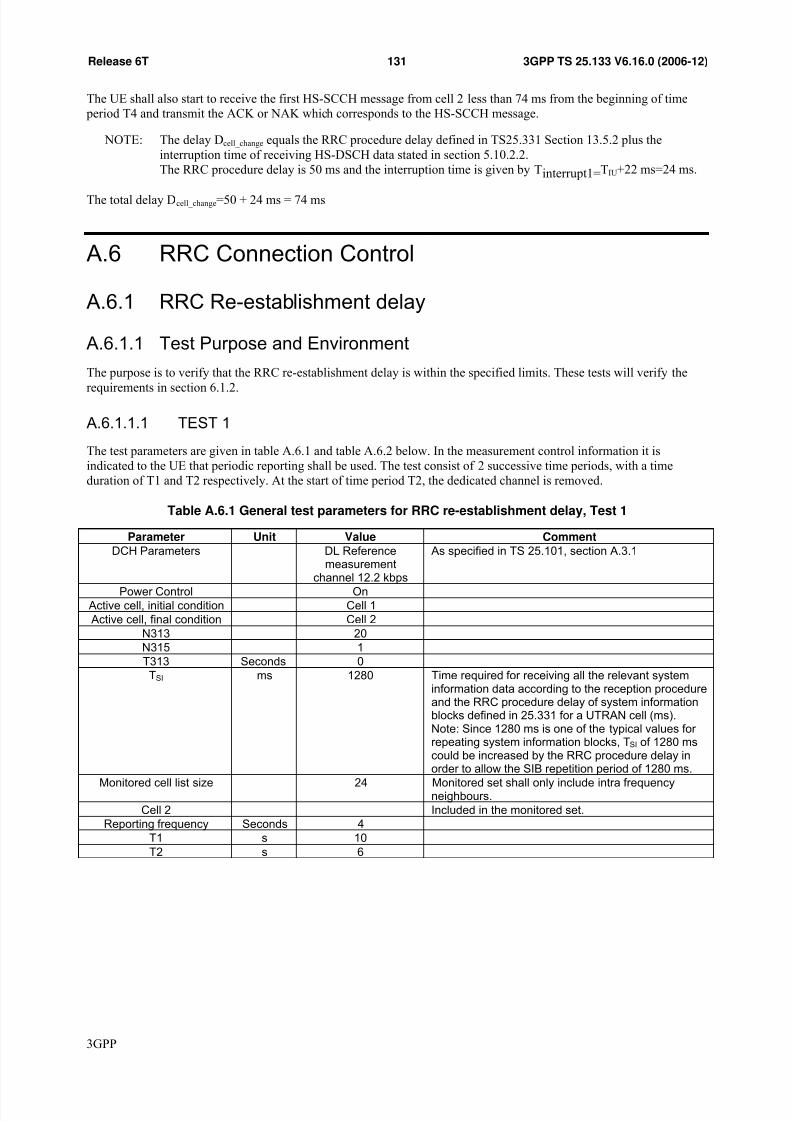
7/31/2019 25133-6g0
http://slidepdf.com/reader/full/25133-6g0 131/190
131Release 6T 3GPP TS 25.133 V6.16.0 (2006-12)
The UE shall also start to receive the first HS-SCCH message from cell 2 less than 74 ms from the beginning of time period T4 and transmit the ACK or NAK which corresponds to the HS-SCCH message.
NOTE: The delay Dcell_change equals the RRC procedure delay defined in TS25.331 Section 13.5.2 plus theinterruption time of receiving HS-DSCH data stated in section 5.10.2.2.The RRC procedure delay is 50 ms and the interruption time is given by Tinterrupt1=TIU+22 ms=24 ms.
The total delay Dcell_change=50 + 24 ms = 74 ms
A.6 RRC Connection Control
A.6.1 RRC Re-establishment delay
A.6.1.1 Test Purpose and Environment
The purpose is to verify that the RRC re-establishment delay is within the specified limits. These tests will verify therequirements in section 6.1.2.
A.6.1.1.1 TEST 1
The test parameters are given in table A.6.1 and table A.6.2 below. In the measurement control information it isindicated to the UE that periodic reporting shall be used. The test consist of 2 successive time periods, with a timeduration of T1 and T2 respectively. At the start of time period T2, the dedicated channel is removed.
Table A.6.1 General test parameters for RRC re-establishment delay, Test 1
Parameter Unit Value Comment
DCH Parameters DL Referencemeasurement
channel 12.2 kbps
As specified in TS 25.101, section A.3.1
Power Control On Active cell, initial condition Cell 1 Active cell, final condition Cell 2
N313 20N315 1T313 Seconds 0TSI ms 1280 Time required for receiving all the relevant system
information data according to the reception procedureand the RRC procedure delay of system informationblocks defined in 25.331 for a UTRAN cell (ms).Note: Since 1280 ms is one of the typical values for repeating system information blocks, TSI of 1280 mscould be increased by the RRC procedure delay in
order to allow the SIB repetition period of 1280 ms.Monitored cell list size 24 Monitored set shall only include intra frequency
neighbours.Cell 2 Included in the monitored set.
Reporting frequency Seconds 4T1 s 10T2 s 6
3GPP

7/31/2019 25133-6g0
http://slidepdf.com/reader/full/25133-6g0 132/190

7/31/2019 25133-6g0
http://slidepdf.com/reader/full/25133-6g0 133/190
133Release 6T 3GPP TS 25.133 V6.16.0 (2006-12)
Table A.6.4 Cell specific parameters for RRC re-establishment delay test, Test 2
Cell 1 Cell 2Parameter UnitT1 T2 T1 T2
Cell Frequency ChNr 1 2CPICH_Ec/Ior dB -10 -10
PCCPCH_Ec/Ior dB -12 -12
SCH_Ec/Ior dB -12 -12PICH_Ec/Ior dB -15 -15DCH_Ec/Ior dB Note 1 -Infinity Not applicable
OCNS_Ec/Ior dB Note 2 -0.941 -0.941
ocor I I ̂ dB -3,35 -Infinity -Infinity 0,02
oc I dBm/ 3.84MHz
-70
CPICH_Ec/Io dB -15 -Infinity -Infinity -13Propagation Condition AWGN
Note 1: The DPCH level is controlled by the power control loopNote 2: The power of the OCNS channel that is added shall make the total power from the cell to be equal to
Ior .
A.6.1.2 Test Requirements
A.6.1.2.1 Test 1
The Re-establishment delay TRE-ESTABLISH to a known cell shall be less than 1.9s.
The rate of correct RRC re-establishments observed during repeated tests shall be at least 90%.
NOTE: The Re-establishment delay in this case can be expressed as
TRE-ESTABLISH= TRRC-RE-ESTABLISH+ TUE-RE-ESTABLISH-REQ-KNOWN.
where
TRRC-RE-ESTABLISH=160ms+(N313-1)*10ms+T313
TUE-RE-ESTABLISH_REQ-KNOWN=50ms+Tsearch + TSI + TRA,
N313=20
T313=0s
Tsearch=100ms
TRA = The additional delay caused by the random access procedure. 40 ms is assumed in this test case.
TSI is the time required for receiving all the relevant system information data according to the reception procedure and the RRC procedure delay of system information blocks defined in 25.331 for a UTRAN cell(ms). 1280 ms is assumed in this test case.
This gives a total of 1820ms, allow 1.9s in the test case.
A.6.1.2.2 Test 2
The Re-establishment delay to an unknown cell shall be less than 4.2s.
The rate of correct RRC re-establishments observed during repeated tests shall be at least 90%.
NOTE: The Re-establishment delay in this case can be expressed as
TRE-ESTABLISH= TRRC-RE-ESTABLISH+ TUE-RE-ESTABLISH-REQ-UNKNOWN.
where
3GPP

7/31/2019 25133-6g0
http://slidepdf.com/reader/full/25133-6g0 134/190
134Release 6T 3GPP TS 25.133 V6.16.0 (2006-12)
TRRC-RE-ESTABLISH=160ms+(N313-1)*10ms+T313
TUE-RE-ESTABLISH-REQ-UNKNOWN=50ms+Tsearch*NF + TSI + TRA,
N313=20
T313=0s
Tsearch=800ms
NF is the number of different frequencies in the monitored set. 3 frequencies are assumed in this test case.
TRA = The additional delay caused by the random access procedure. 40 ms is assumed in this test case.
TSI is the time required for receiving all the relevant system information data according to the reception procedure and the RRC procedure delay of system information blocks defined in 25.331 for a UTRAN cell(ms).1280 ms is assumed in this test case.
This gives a total of 4120ms, allow 4.2s in the test case.
A.6.2 Random Access A.6.2.1 Test Purpose and Environment
The purpose of these tests is to verify that the behaviour of the random access procedure is according to therequirements and that the PRACH power settings and timing are within specified limits. This tests will verify therequirements in section 6.3.2 and section 7.4.2.
Table A.6.5: RF Parameters for Random Access test
Parameter Unit Cell 1
UTRA RF Channel Number Channel 1CPICH_Ec/Ior dB -10PCCPCH_Ec/Ior dB -12SCH_Ec/Ior dB -12Number of other transmitted Acquisition Indicators
- 0
AICH_Ec/Ior dB -10PICH_Ec/Ior dB -15OCNS_Ec/Ior when an AI is nottransmitted
dB -0.941
OCNS_Ec/Ior when an AI istransmitted
dB -1.516
ocor I I ̂ dB 0
oc I dBm/3.84 MHz -70
CPICH_Ec/Io dB -13Propagation Condition AWGN
The test parameters "System Information Block (SIB) type 5 (ASC #0)" defined in section 6.1 of TS34.108, shall beused in all random access tests. Crucial parameters for the test requirements are repeated in Table A.6.6 and A.6.7 andthese overrule the parameters defined in SIB type 5.
3GPP

7/31/2019 25133-6g0
http://slidepdf.com/reader/full/25133-6g0 135/190
135Release 6T 3GPP TS 25.133 V6.16.0 (2006-12)
Table A.6.6: UE parameters for Random Access test
Parameter Unit Value
Access Service Class(ASC#0)
- Persistence value0..1 1
Maximum number of preambleramping cycles (Mmax).
2
Maximum number of preambles in one preambleramping cycle(Preamble Retrans Max)
12
The backoff time TB01 NB01min=NB01max
ms#TTI
N/A10
Power step when noacquisition indicator isreceived(Power offset P0)
dB 3
Power offset between the last
transmitted preamble and thecontrol part of the message(Power offset P p-m)
dB 0
Maximum allowed UL TXpower
dBm 21
Table A.6.7: UTRAN parameters for Random Access test
Parameter Unit Value
Primary CPICH DL TX power dBm -8UL interference dBm -92SIR in open loop power control (Constant value)
dB -10
AICH Power Offset dB 0
A.6.2.2 Test Requirements
A.6.2.2.1 Correct behaviour when receiving an ACK
The UE shall stop transmitting preambles upon a ACK on the AICH has been received and then transmit a message. AnACK shall be transmitted after 10 preambles have been received by the UTRAN.
The absolute power applied to the first preamble shall be -30 dBm with an accuracy as specified in section 6.4.1.1 of TS 25.101 [3]. The relative power applied to additional preambles shall have an accuracy as specified in section 6.5.2.1
of TS 25.101 [3].
The UE shall transmit 10 preambles and 1 message.
The transmit timing of all PRACH transmissions shall be within the accuracy specified in subclause 7.4.2.
A.6.2.2.2 Correct behaviour when receiving an NACK
The UE shall stop transmitting preambles upon a NACK on the AICH has been received and then repeat the ramping procedure when the back off timer TB01 expires. The NACK shall be transmitted after the 10 preambles have beenreceived by the UTRAN.
The UE shall transmit 10 preambles in the first ramping cycle and no transmission shall be done by the UE within 100
ms after the NACK has been transmitted by the UTRAN. Then the UE shall start the second preamble ramping cycle.
3GPP

7/31/2019 25133-6g0
http://slidepdf.com/reader/full/25133-6g0 136/190
136Release 6T 3GPP TS 25.133 V6.16.0 (2006-12)
A.6.2.2.3 Correct behaviour at Time-out
The UE shall stop transmit preambles when reaching the maximum number of preambles allowed in a cycle. The UEshall then repeat the ramping procedure until the maximum number of preamble ramping cycles are reached. NoACK/NACK shall be sent by UTRAN during this test.
The UE shall transmit 2 preambles cycles, consisting of 12 preambles in each preamble cycle.
A.6.2.2.4 Correct behaviour when reaching maximum transmit power
The UE shall not exceed the maximum allowed UL TX power configured by the UTRAN. No ACK/NACK shall besent by UTRAN during this test.
The absolute power of any preambles belonging to the first or second preamble cycle shall not exceed 0 dBm with morethan the tolerance given in section 6.5.
Table A.6.7A: Specific UE parameter for correct behaviour when reaching maximum transmit power
Parameter Unit Value
Maximum allowed UL TX power dBm 0
A.6.3 (void)
A.6.4 Transport format combination selection in UE
A.6.4.1 Test Purpose and Environment
The purpose is to verify the UE blocks (stops using) a currently used TFC when the UE output power is not sufficient tosupport that TFC. This test will verify the general requirement on TFC selection in section 6.4.
A.6.4.1.1 Interactive or Background, PS, UL: 64 kbps
The test will verify the general requirement on TFC selection in section 6.4 for a RAB intended for packet data services,i.e. Interactive or Background, PS, UL: 64kbps as defined in TS 34.108.
The test parameters are given in Table A.6.8 , A.6.9 and Table A.6.10 below. The test consists of 2 successive time periods, with a time duration of T1 and T2 respectively.
Details on the UL reference RAB in table A.6.8 and A.6.9 can be found in TS 34.108 section "Interactive or background/ UL:64 DL: 64 kbps / PS RAB + UL:3.4 DL:3.4 kbps SRBs for DCCH".
Table A.6.8: UL reference RAB, Interactive or Background
TFI 64 kbps RAB (20ms TTI) DCCH 3.4kbps (40ms TTI)TF0, bits 0x336 0x148TF1, bits 1x336 1x148TF2, bits 2x336 N/ATF3, bits 3x336 N/A
TFS
TF4, bits 4x336 N/A
3GPP

7/31/2019 25133-6g0
http://slidepdf.com/reader/full/25133-6g0 137/190
137Release 6T 3GPP TS 25.133 V6.16.0 (2006-12)
Table A.6.9: UL TFCI
TFCI (64 kbps RAB, DCCH)
UL_TFC0 (TF0, TF0)UL_TFC1 (TF0, TF1)UL_TFC2 (TF1, TF0)UL_TFC3 (TF1, TF1)
UL_TFC4 (TF2, TF0)UL_TFC5 (TF2, TF1)UL_TFC6 (TF3, TF0)UL_TFC7 (TF3, TF1)UL_TFC8 (TF4, TF0)UL_TFC9 (TF4, TF1)
Table A.6.10: General test parameters
Parameter Unit Value Comment
TFCS size 10TFCS UL_TFC0, UL_TFC1, UL_TFC2,
UL_TFC3, UL_TFC4, UL_TFC5,UL_TFC6, UL_TFC7, UL_TFC8,UL_TFC9
Power Control On Active cell Cell 1
Maximum allowed UL TXpower
dBm 21
T1 s 30T2 s 2
Propagation condition AWGN
The radio conditions in the test shall be sufficient, so that decoding of the TPC commands can be made without errors.
The amount of available user data shall be sufficient to allow uplink transmission at the highest bit rate (UL_TFC8 or UL_TFC9) during the entire test and it shall be ensured that the UE is using UL_TFC8 or UL_TFC9 at the end of T1.
The test shall be performed in the following way:
Before time period T1:
The allowed TFCS according to table A.6.10 shall be signalled to the UE.
During time period T1:
The system simulator shall ensure that the UE output power is commanded to be between 14 to 15 dB below the UEMaximum allowed UL TX power.
During time period T2:
The system simulator shall continously send TPC_cmd=1 to the UE from the beginning of T2 until the end of T2.
NOTE: This will emulate that UL_TFC8 to UL_TFC9 can not be supported beacuse the UE reaches themaximum UL Tx power and still UTRAN is sending power-up commands. The time from the beginningof T2 until the UE blocks (stops using) UL_TFC8 and UL_TFC9 shall be measured.
A.6.4.2 Test Requirements
A.6.4.2.1 Interactive or Background, PS, UL: 64 kbps
The UE shall have stopped using UL_TFC8 and UL_TFC9 within 140 ms from beginning of time period T2.
The rate of correct tests observed during repeated tests shall be at least 90%.
NOTE: The delay from the begining of T2 can be expressed as:
3GPP

7/31/2019 25133-6g0
http://slidepdf.com/reader/full/25133-6g0 138/190
138Release 6T 3GPP TS 25.133 V6.16.0 (2006-12)
Tramp + Tdetect_block + Tnotify + Tmodify+ TL1_proc + Talign_TTI
where:
Tramp Margin added for the increase of UE output power to the UE maximum power. A margin of 1frame (10ms) is used, i.e. 15 TPC commands.
Tdetect_block The time needed to detect that UL_TFC8 and UL_TFC9 can no longer be supported, i.e. definesthe maximum time to detect that the Elimination criterion is fulfilled for UL_TFC8 and UL_TFC9.According to X and Y values of 15 and 30 as defined in Section 6.4.2 and by assuming themaximum misalignment between the frame boundary, where the evaluation of the Elimination criterion is performed and the last slot needed for triggering the Elimination criterion on L1,Tdetect_block becomes 15 slots +14 slots =19.33 ms.
Tnotify Equal to 15 ms, the time allowed for MAC to indicate to higher layers that UL_TFC8 andUL_TFC9 can no longer be supported.
Tmodify Equal to MAX(Tadapt_max,TTTI) = MAX(0, 40)=40ms
Tadapt_max Equals to 0ms for the case without codec.
TL1_proc Equals 15ms.
Talign_TTI Align with the longest uplink TTI where the new TFC can be selected. The worst case equals40ms in this test case.
TTTI See section 6.4.2. Equals 40 ms in the test case.
This gives a maximum delay of (10 + 19.33 + 15 + 40 + 15 + 40) ms= 139.33 ms from the beginning of T2, allow 140ms in the test case.
A.6.5 (void)
Table A.6.11: (void)
Table A.6.12: (void)
Table A.6.13: (void)
A.6.6 E-TFC restriction in UE A.6.6.1 Test Purpose and Environment
The purpose is to verify the UE stops using a currently used E-TFC when its remaining power margin is not sufficientto support that E-TFC. This test will verify the general requirement on E-TFC selection in section 6.4.
A.6.6.1.1 10ms TTI E-DCH E-TFC restriction testcase
The test will verify the general requirement on E-TFC restriction in section 6.4 for a 10ms TTI E-DCH Transport Block Size Table 0 [19]
The test parameters are given in Table A.6.14 below. The test consists of 2 successive time periods, with a time
duration of T1 and T2 respectively.
3GPP

7/31/2019 25133-6g0
http://slidepdf.com/reader/full/25133-6g0 139/190
139Release 6T 3GPP TS 25.133 V6.16.0 (2006-12)
The UE shall be configured to transmit UL DTCH data continuously on the DPCH. An HSDPA radio bearer shall beconfigured so that the UE transmits ACK and UL HS-DPCCH. An E-DCH radio bearer shall be configured, so that UEis transmitting E-DPCCH and E-DPDCH.
Table A.6.14: General test parameters
Parameter Unit Value Comment
UL DPCH configuration 12.2kbps referencemeasurement channel
E-DCH Transport BlockSize Table
10ms TTI E-DCH TransportBlock Size Table 0 according to
25.321 annex B.3UL Power Control On
Active cell Cell 1Maximum allowed UL TX
power dBm 24 For a class 4 UE
maximum allowed TXpower can still be
signalled as 24dBmhowever the UE only
has capability to transmit21dBm
Propagation condition AWGNβd/βC 9/15 Care needs to be taken
to ensure that TFCS withβd/βC =9/15 is always
used even during power limited part of the test in
T2 Ahs 2 Δ ACK=ΔNACK=ΔCQI
Aec 2βed,ref /βC 5/15
Lref 1
Kref 18
Δharq dB 0
PLnon-max 0.52
E-DCH minimum set E-TFI 0 Makes E-DCH transportblock size with index 0unblockable even inpower limited phase
Periodicity for SchedulingInfo
Every TTI Ensures that some datais sent on every TTI
even in the power limitedphase
E-DCH MAC-d flowmaximum number of
retransmissions
0
T1 s 30T2 s 2
The radio conditions in the test shall be sufficient, so that decoding of the TPC commands can be made without errors.
The amount of available user data shall be sufficient to allow E-DCH uplink transmission at the highest possible bit ratewith E-DCH TB index 127. It shall also be ensured that sufficient data is made available on the DTCH so that the UE iscontinuously transmitting on the DPCH.
The test shall be performed in the following way:
Before time period T1:
Call is established with DCH, HSDPA and E-DCH radio bearers. "UP" commands are sent on E-RGCH to give UEgrants to make use of the maximum possible data rate.
3GPP

7/31/2019 25133-6g0
http://slidepdf.com/reader/full/25133-6g0 140/190
140Release 6T 3GPP TS 25.133 V6.16.0 (2006-12)
During time period T1:
The system simulator shall ensure that the UE PDPCCH power is commanded to be between 0dBm and 1dBm for a power class 3 UE, or between -3dBm and -2dBm for a power class 4 UE. Within 45ms from the start of T1, the UE shall beusing E-TFC with index 127, or the E-TFC index which represents the maximum of the UE’s capabilities.
During time period T2:
The system simulator shall continuously send TPC_cmd=1 to the UE from the beginning of T2 until the end of T2.Within 45ms of the start of T2, the UE shall be using E-TFC with index 0 only.
Time periods T1 and T2 shall be repeated until the necessary statistical confidence is achieved.
A.6.6.1.1.1 Test Requirements
During time period T1, uplink power control shall be adjusted so that the UE is able to make use of E-TFC index 127,or the maximum of its capabilities if this is lower.
Note : The required headroom to support E-TFC 127 can be calculated using the parameters Lref =1, K ref =18 andK 127=20000. This requires {(5006)*3+12}*4=60120 before rate matching/ARQ. This can be transmitted on 2xSF/2
codes, so needs equivalent of 4xSF/4 codes, giving L127=4.
Substituting into the equation for βed,j,harq from 25.214:
20, ,, , ,
, ,
10harq
e ref e j
ed j harq ed ref
e j e ref
L K
L K β β
Δ⎛ ⎞⎜ ⎟⎜ ⎟⎝ ⎠= ⋅
gives
βed,j,harq= 5 * sqrt (1/4) * sqrt (20000 / 18) = 83.333
For the SF/2 case, the unquantised gain factor β ed,k,j,uq for each of these two codes is according to
β ed,k,j,uq= β ed,k,j,uq= , ,2ed j harq
β ×
β ed,k,j,uq= sqrt(2) * 83.333 = 117.85
β ed,k is set such that β ed,k / β c is the largest quantized value of Table 1B.2 in [3] subclause 4.2.1.3, for which the condition β ed,k ≤ β ed,k,j,uq holds.
According to 25.213 Table 1B.2 in subclause 4.2.1.3, the corresponding quantised amplitude ratio has index 25,Aed = βed/βc= 106/15 for each of the two SF/2 E-DPDCH codes.
The E-TFC selection MPR for this case from 25.133 table 6.2 corresponds to case 6, or an E-TFC MPR of 0.5dB.
⎟⎟ ⎠
⎞⎜⎜⎝
⎛ +++−=
+++−=
−−−= −−
222
2
2
2222
1
-
hsec
c
d
DPCCH
j
c
hsecd c
DPCCH
j
DPCCH DPCCH E DPCCH HS DPDCH DPCCH j
A AP
PMax
P
PMax
PPPPPPMax NRPM j
β
β
β
β β β β
For a power class 3 UE PMax j = 23.5dBm = 223.87mW, or for a power class 4 UE, PMax j = 20.5dBm = 112.20mW
The inequality for support of E-TFC with index 127 is
223.87/PDPCCH - (1+ (9
2
/15
2
) + 2
2
+ 2
2
) ≥ 106
2
/15
2
+ 106
2
/15
2
(class 3)112.20/PDPCCH - (1+ (92/152) + 22 + 22 ) ≥ 1062/152 + 1062/152 (class 4)
3GPP

7/31/2019 25133-6g0
http://slidepdf.com/reader/full/25133-6g0 141/190
141Release 6T 3GPP TS 25.133 V6.16.0 (2006-12)
This is satisfied if PDPCCH ≤ (223.87/109.23) = 2.04mW = 3.11dBm for a class 3 UE or PDPCCH ≤ (112.20/109.23) =1.03mW = 0.12dBm for a class 4 UE
From table 6.0A the accuracy of the PDPCCH estimate used for E-TFC selection in this scenario is ±2dB for power class 3or ±2.5dB for power class 4. Therefore, for PDPCCH ≤ 1.11dBm (class 3) or -2.38dBm (class 4), the UE shall be able tosupport E-TFC index 127. Since power control granularity is 1dB, the UE output power should be maintained so that0dBm
≤P
DPCCH≤1dBm throughout this phase for a class 3 UE, or so that -3dBm
≤P
DPCCH≤-2dBm throughout this
phase for a class 4 UE.
Note: Test tolerance may need to be added to further reduce the UE DPCCH power further by RAN5,depending on how accurately tester can set and maintain UE DPCCH power.
Note: The required time to start using E-TFC index 127 or the maximum of the UEs cababilites at the beginningof T1, and to start using E-TFC with index 0 at the beginning of T2 can be calculated as follows
Since TPC commands are received error free by the UE, PDPCCH shall reach the new power level power within 25 slots =16.666ms.
The UE shall have evaluated and started to use the new restriction criteria with Ts = (Power level change time + PDPCCH filtering period + E-TFC estimation rate + Maximum time from RGCH reception to E-TFC transmission) from the start
of the time period= 16.66ms + 10ms + 10ms + 7.53ms
= 44.19ms, allow 45ms
The rate of correct tests observed during repeated tests shall be at least 90%.
A.6.6.1.2 2ms TTI E-DCH E-TFC restriction testcase
The test will verify the general requirement on E-TFC restriction in section 6.4 for a 2ms TTI E-DCH Transport Block Size Table 0 [19]
The test parameters are given in Table A.6.15 below. The test consists of 2 successive time periods, with a time
duration of T1 and T2 respectively.
The UE shall be configured to transmit UL DTCH data continuously on the DPCH. An HSDPA radio bearer shall beconfigured so that the UE transmits ACK and UL HS-DPCCH. An E-DCH radio bearer shall be configured, so that UEis transmitting E-DPCCH and E-DPDCH.
3GPP

7/31/2019 25133-6g0
http://slidepdf.com/reader/full/25133-6g0 142/190
142Release 6T 3GPP TS 25.133 V6.16.0 (2006-12)
Table A.6.15: General test parameters
Parameter Unit Value Comment
UL DPCH configuration 12.2kbps referencemeasurement channel
E-DCH Transport BlockSize Table
2ms TTI E-DCH Transport BlockSize Table 0 according to
25.321 annex B.1UL Power Control On
Active cell Cell 1Maximum allowed UL TX
power dBm 24 For a class 4 UE
maximum allowed TXpower can still be
signalled as 24dBmhowever the UE only
has capability to transmit21dBm
Propagation condition AWGNβd/βC 9/15 Care needs to be taken
to ensure that TFCS withβd/βC =9/15 is always
used even during power limited part of the test in
T2 Ahs 2 Δ ACK=ΔNACK=ΔCQI
Aec 2βed,ref /βC 5/15
Lref 1
Kref 18
Δharq dB 0
PLnon-max 0.52
E-DCH minimum set E-TFI 0 Makes E-DCH transportblock size with index 0unblockable even inpower limited phase
Periodicity for SchedulingInfo
Every TTI Ensures that some datais sent on every TTI
even in the power limitedphase
E-DCH MAC-d flowmaximum number of
retransmissions
0
T1 s 30T2 s 2
The radio conditions in the test shall be sufficient, so that decoding of the TPC commands can be made without errors.
The amount of available user data shall be sufficient to allow E-DCH uplink transmission at the highest possible bit ratewith E-DCH TB index 127. It shall also be ensured that sufficient data is made available on the DTCH so that the UE iscontinuously transmitting on the DPCH.
The test shall be performed in the following way:
Before time period T1:
Call is established with DCH, HSDPA and E-DCH radio bearers. "UP" commands are sent on E-RGCH to give UEgrants to make use of the maximum possible data rate.
During time period T1:
3GPP

7/31/2019 25133-6g0
http://slidepdf.com/reader/full/25133-6g0 143/190
143Release 6T 3GPP TS 25.133 V6.16.0 (2006-12)
The system simulator shall ensure that the UE PDPCCH power is commanded to be between 3dBm and 4dBm for a power class 3 UE, or between 0dBm and 1dBm for a power class 4 UE. Within 23ms from the start of T1, the UE shall beusing E-TFC with index 127, or the E-TFC index which represents the maximum of the UE’s capabilities.
During time period T2:
The system simulator shall continuously send TPC_cmd=1 to the UE from the beginning of T2 until the end of T2.Within 23ms of the start of T2, the UE shall be using E-TFC with index 0 only.
Time periods T1 and T2 shall be repeated until the necessary statistical confidence is achieved.
A.6.6.1.2.1 Test Requirements
During time period T1, uplink power control shall be adjusted so that the UE is able to make use of E-TFC index 127,or the maximum of its capabilities if this is lower.
Note : The required headroom to support E-TFC 127 can be calculated using the parameters Lref =1, K ref =18 andK 127=11484. This requires {(3836)*3+12}*3 =34560 bits before rate matching/ARQ. This can be transmitted on 2xSF/2codes and 2xSF/4 codes, so needs equivalent of 6xSF/4 codes, giving L127=6.
Substituting into the equation for βed,j,harq from 25.214:
20, ,, , ,
, ,
10harq
e ref e j
ed j harq ed ref
e j e ref
L K
L K β β
Δ⎛ ⎞⎜ ⎟⎜ ⎟⎝ ⎠= ⋅
gives
βed,j,harq= 5 * sqrt (1/6) * sqrt (11484 / 18) = 51.56
For the SF/2 codes, the unquantised gain factor β ed,k,j,uq for each of these two codes is according to β ed,k,j,uq= β ed,k,j,uq=
, ,2ed j harq
β ×
β ed,k,j,uq= sqrt(2) * 51.56 = 72.91
And for the SF/4 codes, the unquantised gain factor is β ed,k,j,uq =51.56
β ed,k is set such that β ed,k / β c is the largest quantized value of Table 1B.2 in [3] subclause 4.2.1.3, for which the condition β ed,k ≤ β ed,k,j,uq holds.
According to 25.213 Table 1B.2 in subclause 4.2.1.3, the corresponding quantised amplitude ratio are Aed = βed/βc=67/15 for each of the two SF/2 E-DPDCH codes and Aed = βed/βc= 47/15 for each of the two SF/4 codes
The E-TFC selection MPR for this case from 25.133 table 6.2 is 0.0dB.
⎟⎟ ⎠
⎞⎜⎜⎝
⎛ +++−=
+++−=
−−−= −−
222
2
2
2222
1
-
hsec
c
d
DPCCH
j
c
hsecd c
DPCCH
j
DPCCH DPCCH E DPCCH HS DPDCH DPCCH j
A AP
PMax
P
PMax
PPPPPPMax NRPM j
β
β
β
β β β β
For a power class 3 UE PMax j = 24dBm = 251.2mW, or for a power class 4 UE, PMax j = 21dBm = 125.9mW
The inequality for support of E-TFC with index 127 is
251.2/PDPCCH - (1+ (92/152) + 22 + 22 ) ≥ 472/152 + 472/152 +672/152 + 672/152 (class 3)
125.9/PDPCCH - (1+ (92/152) + 22 + 22 ) ≥ 472/152 + 472/152 +672/152 + 672/152 (class 4)
3GPP

7/31/2019 25133-6g0
http://slidepdf.com/reader/full/25133-6g0 144/190
144Release 6T 3GPP TS 25.133 V6.16.0 (2006-12)
This is satisfied if PDPCCH ≤ (251.2/68.9) = 3.64mW = 5.61dBm for a class 3 UE or PDPCCH ≤ (125.9/68.9) = 1.82mW =2.61dBm for a class 4 UE
From table 6.0A the accuracy of the Pdpcch estimate used for E-TFC selection in this scenario is ±2dB for power class3 or ±2.5dB for power class 4. Therefore, for PDPCCH ≤ 3.61dBm (class 3) or 0.11dBm (class 4), the UE shall be able tosupport E-TFC index 127. Since power control granularity is 1dB, the UE output power should be maintained so that3dBm ≤ PDPCCH≤ 4dBm throughout this phase for a class 3 UE, or so that 0dBm ≤ PDPCCH≤ 1dBm throughout this phasefor a class 4 UE.
Note: Test tolerance may need to be added to further reduce the UE DPCCH power further by RAN5, depending onhow accurately tester can set and maintain UE DPCCH power.
Note : The required time to start using E-TFC index 127 or the maximum of the UEs cababilites at the beginning of T1,and to start using E-TFC with index 0 at the beginning of T2 can be calculated as follows
Since TPC commands are received error free by the UE, PDPCCH shall reach the new power level power within 20 slots =13.33ms.
The UE shall have evaluated and started to use the new restriction criteria with Ts
= (Power level change time + Pdpcchfiltering period + E-TFC estimation rate + Maximum time from RGCH reception to E-TFC transmission) from the startof the time period
= 13.33ms + 2ms + 2ms + 5.53ms
= 22.86ms, allow 23ms
The rate of correct tests observed during repeated tests shall be at least 90%.
A.7 Timing and Signalling Characteristics
A.7.1 UE Transmit Timing
A.7.1.1 Test Purpose and Environment
The purpose of this test is to verify that the UE initial transmit timing accuracy, maximum amount of timing change inone adjustment, minimum and maximum adjustment rate are within the specified limits. This test will verify therequirements in section 7.1.2.
For this test two cells on the same frequency are used. Table A.7.1 defines the transmitted signal strengths, the relativetiming and the propagation condition used for the two cells.
Table A.7.1: Test parameters for UE Transmit Timing requirement
Parameter Unit Level
DPCH_Ec/ Ior, Cell 1 and Cell 2 dB -13.5
CPICH_Ec/ Ior, Cell 1 and Cell 2 dB -10PCCPH_Ec/ Ior, Cell 1 and Cell 2 dB -12SCH_Ec/ Ior, Cell 1 and Cell 2 dB -12PICH_Ec/ Ior, Cell 1 and Cell 2 dB -15OCNS_Ec/ Ior, Cell 1 and Cell 2 dB -1.2 Î or, Cell 1 dBm/3.84 MHz -96
Î or, Cell 2 dBm/3.84 MHz -99
Information data rate kbps 12.2Relative delay of path received from cell
2 with respect to cell 1
μs +/-2
Propagation condition AWGN
3GPP

7/31/2019 25133-6g0
http://slidepdf.com/reader/full/25133-6g0 145/190
145Release 6T 3GPP TS 25.133 V6.16.0 (2006-12)
A.7.1.2 Test Requirements
For parameters specified in Table A.7.1, the UE initial transmit timing accuracy, the maximum amount of timingchange in one adjustment, the minimum and the maximum adjustment rate shall be within the limits defined in section7.1.2.
The relevant soft handover parameters shall be set such that the UE enters soft handover with cell 1 andcell 2 when both cells are sending a signal. The following sequence of events shall be used to verify that therequirements are met.
a) After a connection is set up with cell 1, the test system shall verify that the UE transmit timing offset is within T0 +/-1.5 chips with respect to the first detected received path (in time) of the downlink DPCCH/DPDCH of cell 1. T0 isdefined in TS 25.211[2].
b) Test system introduces cell 2 into the test system at delay +2 μs from cell 1.
c) Test system verifies that cell 2 is added to the active set.
d) Test system shall verify that the UE transmit timing offset is still within T0 +/- 1.5 chips with respect to the firstdetected path (in time) of the downlink DPCCH/DPDCH of cell 1.
e) Test system switches Tx timing of cell 2 to a delay of -2 μs with respect to cell 1.
f) Test system verifies cell 2 remains in the active set.
g) Test system shall verify that the UE transmit timing offset is still within T0 +/- 1.5 chips with respect to the firstdetected path (in time) of the downlink DPCCH/DPDCH of cell 1.
h) Test system stops sending cell 1 signals.
i) Test system verifies that UE transmit timing adjustment starts no later than the time when the whole active setupdate message is available at the UE taking the RRC procedure delay into account. The adjustment step size andthe adjustment rate shall be according to the requirements in section 7.1.2 until the UE transmit timing offset iswithin T0 +/- 1.5 chips with respect to the first detected path (in time) of the downlink DPCCH/DPDCH of cell 2.
j) Test system shall verify that the UE transmit timing offset stays within T0 +/- 1.5 chips with respect to the firstdetected path (in time) of the downlink DPCCH/DPDCH of cell 2.
k) Test system starts sending cell 1 signal again with its original timing.
l) Test system verifies that cell 1 is added to the active set.
m) Test system verifies that the UE transmit timing is still within T0 +/- 1.5chips with respect to the first detected path(in time) of the downlink DPCCH/DPDCH of cell 2.
n) Test system stops sending cell 2 signals.
o) Test system verifies that UE transmit timing adjustment starts no later than the time when the whole active set
update message is available at the UE taking the RRC procedure delay into account. The adjustment step size andthe adjustment rate shall be according to the requirements in section 7.1.2 until the UE transmit timing offset iswithin T0 +/- 1.5 chips with respect to the first detected path (in time) of the downlink DPCCH/DPDCH of cell 1.
p) Test system shall verify that the UE transmit timing offset stays within T0 +/- 1.5 chips with respect to the firstdetected path (in time) of the downlink DPCCH/DPDCH of cell 1.
3GPP

7/31/2019 25133-6g0
http://slidepdf.com/reader/full/25133-6g0 146/190
146Release 6T 3GPP TS 25.133 V6.16.0 (2006-12)
A.8 UE Measurements Procedures
A.8.1 FDD intra frequency measurements
A.8.1.1 Event triggered reporting in AWGN propagation conditions
A.8.1.1.1 Test Purpose and Environment
The purpose of this test is to verify that the UE makes correct reporting of an event. This test will partly verify therequirements in section 8.1.2 and 9.1.
The test parameters are given in Table A.8.1 and A.8.2 below. In the measurement control information it is indicated tothe UE that event-triggered reporting with Event 1A and 1B shall be used. The test consists of three successive time
periods, with a time duration of T1, T2 and T3 respectively. During time duration T1, the UE shall not have any timinginformation of cell 2.
Table A.8.1: General test parameters for Event triggered reporting in AWGN propagation conditions
Parameter Unit Value Comment
DCH parameters DL Reference MeasurementChannel 12.2 kbps
As specified in TS 25.101 section A.3.1
Power Control On Active cell Cell 1Reporting range dB 3 Applicable for event 1A and 1BHysteresis dB 0W 1 Applicable for event 1A and 1BReporting deactivationthreshold
0 Applicable for event 1A
Time to Trigger ms 0Filter coefficient 0
Monitored cell list size 24T1 s 5T2 s 5T3 s 5
Table A.8.2: Cell specific test parameters for Event triggered reporting in AWGN propagationconditions
Cell 1 Cell 2Parameter UnitT1 T2 T3 T1 T2 T3
CPICH_Ec/Ior dB -10 -10PCCPCH_Ec/Ior dB -12 -12SCH_Ec/Ior dB -12 -12PICH_Ec/Ior dB -15 -15DPCH_Ec/Ior dB Note 1 N/AOCNS Note 2 -0.941
ocor I I ̂ dB 0 6.97 0 -Infinity 5.97 -Infinity
oc I dBm/3.84MHz
-70
CPICH_Ec/Io dB -13 -13 -13 -Infinity -14 -InfinityPropagationCondition
AWGN
Note 1: The DPCH level is controlled by the power control loopNote 2: The power of the OCNS channel that is added shall make the total power from the cell to be equal to Ior .
3GPP

7/31/2019 25133-6g0
http://slidepdf.com/reader/full/25133-6g0 147/190
147Release 6T 3GPP TS 25.133 V6.16.0 (2006-12)
A.8.1.1.2 Test Requirements
The UE shall send one Event 1A triggered measurement report, with a measurement reporting delay less than 800 msfrom the beginning of time period T2.
The UE shall send one Event 1B triggered measurement report, with a measurement reporting delay less than 200 msfrom the beginning of time period T3.
The UE shall not send event triggered measurement reports, as long as the reporting criteria are not fulfilled.
The rate of correct events observed during repeated tests shall be at least 90%.
NOTE: The actual overall delays measured in the test may be up to 2 x TTIUL DCCH higher than the measurementreporting delays above because of TTI insertion uncertainty of the measurement report in the UL DCCH.
A.8.1.2 Event triggered reporting of multiple neighbours in AWGNpropagation condition
A.8.1.2.1 Test Purpose and EnvironmentThe purpose of this test is to verify that the UE makes correct reporting of events. This test will partly verify therequirements in section 8.1.2 and 9.1.
The test parameters are given in Table A.8.3 and A.8.4. In the measurement control information it is indicated to the UEthat event-triggered reporting with Event 1A, 1C and 1B shall be used and the periodical reporting of the events is notapplied. The test consists of four successive time periods, with a time duration of T1, T2, T3 and T4 respectively. In theinitial condition before the time T1 only Cell1 is active.
Table A.8.3: General test parameters for Event triggered reporting of multiple neighbours in AWGNpropagation conditions
Parameter Unit Value Comment
DCH parameters DL Reference Measurement Channel12.2 kbps As specified in TS 25.101 section A.3.1
Power Control On Active cell Cell 1Reporting range dB 3 Applicable for event 1A and 1BHysteresis dB 0W 1 Applicable for event 1A and 1BReplacementactivation threshold
0 Applicable for event 1C
Reportingdeactivationthreshold
0 Applicable for event 1A
Time to Trigger ms 0Filter coefficient 0
Monitored cell listsize
32
T1 S 10T2 S 10T3 S 5T4 S 10
3GPP

7/31/2019 25133-6g0
http://slidepdf.com/reader/full/25133-6g0 148/190
148Release 6T 3GPP TS 25.133 V6.16.0 (2006-12)
Table A.8.4: Cell specific test parameters for Event triggered reporting of multiple neighbours inAWGN propagation condition
Cell 1 Cell 2 Cell3Parameter UnitT1 T2 T3 T4 T1 T2 T3 T4 T1 T2 T3 T4
CPICH_Ec/Ior dB -10 -10 -10PCCPCH_Ec/
Ior dB -12 -12 -12SCH_Ec/Ior dB -12 -12 -12PICH_Ec/Ior dB -15 -15 -15DPCH_Ec/Ior dB Note 1 N/A N/AOCNS_Ec/Ior dB Note 2 -0.941 -0.941
ocor I I ̂ dB 6.97 6.93 5.97 6.12 -Inf 9.43 6.97 7.62 5.97 6.93 -Inf 5.62
oc I dBm/3.84MHz
-85
CPICH_Ec/Io dB -13 -16 -14 -15.5 -Inf -13.5 -13 -14 -14 -16 -Inf -16PropagationCondition
AWGN
Note 1: The DPCH level is controlled by the power control loop
Note 2: The power of the OCNS channel that is added shall make the total power from the cell to be equal to Ior .
A.8.1.2.2 Test Requirements
a) The UE shall send one Event 1A triggered measurement report for Cell3, with a measurement reporting delayless than 800 ms from the beginning of time period T1.
b) The UE may send one Event 1C triggered measurement report for Cell3 after the beginning of the time periodT1.
c) The UE shall send one Event 1C triggered measurement report for Cell2, with a measurement reporting delayless than 800 ms from the beginning of time period T2.
d) The UE shall send one Event 1A triggered measurement report for Cell2, with a measurement reporting delayless than 800 ms from the beginning of time period T2.
e) The UE shall send one Event 1B triggered measurement report for Cell3, with a measurement reporting delayless than 200 ms from the beginning of time period T3.
f) The UE shall send one Event 1A triggered measurement report for Cell3, with a measurement reporting delayless than 200 ms from the beginning of time period T4.
g) The UE may send one Event 1C triggered measurement report for Cell2 after the beginning of the time periodT4.
h) The UE may send one Event 1C triggered measurement report for Cell3 after the beginning of the time period
T4.
i) The UE shall not send event triggered measurement reports, as long as the reporting criteria are not fulfilled.
The rate of correct events observed during repeated tests shall be at least 90%.
NOTE: The actual overall delays measured in the test may be up to 2 x TTIUL DCCH higher than the measurementreporting delays above because of TTI insertion uncertainty of the measurement report in the UL DCCH.
A.8.1.3 Event triggered reporting of two detectable neighbours in AWGNpropagation condition
A.8.1.3.1 Test Purpose and EnvironmentThe purpose of this test is to verify that the UE makes correct reporting of events. This test will partly verify therequirements in section 8.1.2 and 9.1.
3GPP

7/31/2019 25133-6g0
http://slidepdf.com/reader/full/25133-6g0 149/190
149Release 6T 3GPP TS 25.133 V6.16.0 (2006-12)
The test parameters are given in Table A.8.5 and A.8.6. In the measurement control information it is indicated to the UEthat event-triggered reporting with Event 1A and 1B shall be used and the periodical reporting of the events is notapplied. The test consists of four successive time periods, with a time duration of T1, T2, T3 and T4 respectively. In theinitial condition before the time T1 only Cell1 is active.
Table A.8.5: General test parameters for Event triggered reporting of two detectable neighbours in
AWGN propagation condition
Parameter Unit Value CommentDCH parameters DL Reference Measurement
Channel 12.2 kbps As specified in TS 25.101 section A.3.1
Power Control On Active cell Cell 1Reporting range dB 3 Applicable for event 1A and 1BHysteresis dB 0W 1 Applicable for event 1A and 1BReporting deactivationthreshold
0 Applicable for event 1A
Time to Trigger ms 0Filter coefficient 0
Monitored cell list size 32T1 s 10T2 s 10T3 s 10T4 s 10
Table A.8.6: Cell specific test parameters for Event triggered reporting of two detectable neighboursin AWGN propagation condition
Cell 1 Cell 2 Cell3Parameter Unit
T1 T2 T3 T4 T1 T2 T3 T4 T1 T2 T3 T4
CPICH_Ec/Ior dB -10 -10 -10PCCPCH_Ec/Ior dB -12
-12 -12
SCH_Ec/Ior dB -12 -12 -12PICH_Ec/Ior dB -15 -15 -15DPCH_Ec/Ior dB Note 1 N/A N/AOCNS_Ec/Ior dB Note 2 -0.941 -0.941
ocor I I ̂ dB 14.55 28.51 14.45 28.51 -Inf 27.51 13.95 21.51 8.05 21.51 13.95 27.51
oc I dBm/3.84MHz
-85
CPICH_Ec/Io dB -11 -13 -14.5 -13 -Inf -14.0 -15 -20 -17.5 -20 -15 -14PropagationCondition
AWGN
Note 1: The DPCH level is controlled by the power control loop
Note 2: The power of the OCNS channel that is added shall make the total power from the cell to be equal to Ior
A.8.1.3.2 Test Requirements
a) The UE shall send one Event 1A triggered measurement report for Cell2, with a measurement reporting delayless than 800 ms from the beginning of time period T2.
b) The UE shall send one Event 1A triggered measurement report for Cell3, with a measurement reporting delayless than 200 ms from the beginning of time period T3.
c) The UE shall send one Event 1B triggered measurement report for Cell2, with a measurement reporting delayless than 200 ms from the beginning of time period T4.
d) The UE shall not send event triggered measurement reports, as long as the reporting criteria are not fulfilled.
The rate of correct events observed during repeated tests shall be at least 90%.
3GPP

7/31/2019 25133-6g0
http://slidepdf.com/reader/full/25133-6g0 150/190
150Release 6T 3GPP TS 25.133 V6.16.0 (2006-12)
NOTE: The actual overall delays measured in the test may be up to 2 x TTIUL DCCH higher than the measurementreporting delays above because of TTI insertion uncertainty of the measurement report in the UL DCCH.
A.8.1.4 Correct reporting of neighbours in fading propagation condition
A.8.1.4.1 Test Purpose and EnvironmentThe purpose of this test is to verify that the UE performs sufficient layer 1 filtering of the measurements, see section9.1, which are the base for the event evaluation. The test is performed in fading propagation conditions. This test will
partly verify the requirements in section 8.1.2.
The test parameters are given in Table A.8.7 and A.8.8.In the measurement control information it is indicated to the UEthat event-triggered reporting with Event 1A and Event 1B shall be used. The test consists of two successive time
periods, each with a time duration of T1 and T2 respectively.
The TTI of the uplink DCCH shall be 20ms.
Table A.8.7: General test parameters for correct reporting of neighbours in fading propagationcondition
Parameter Unit Value Comment
DCH parameters DL Reference Measurement Channel12.2 kbps
As specified in TS 25.101 section A.3.1
Power Control On Active cell Cell 1Reporting range dB 0 Applicable for event 1A and 1BHysteresis dB 0W 1 Applicable for event 1A and 1BReporting deactivationthreshold
0 Applicable for event 1A
Time to Trigger ms 120Filter coefficient 0Monitored cell list size 24 Signalled before time T1.T1 s 200T2 s 201
Table A.8.8: Cell specific test parameters for correct reporting of neighbours in fading propagationcondition
Cell 1 Cell 2Parameter UnitT1 T2 T1 T2
CPICH_Ec/Ior dB -10 -10PCCPCH_Ec/Ior dB -12 -12SCH_Ec/Ior dB -12 -12PICH_Ec/Ior dB -15 -15
DPCH_Ec/Ior dB Note 1 N/AOCNS Note 2 -0.941
ocor I I ̂ dB 7.29 3.29 3.29 7.29
oc I dBm/3.84MHz
-70
CPICH_Ec/Io dB -12 -16 -16 -12PropagationCondition
Case 5 as specified in Annex B of TS25.101
Note 1: The DPCH level is controlled by the power control loopNote 2: The power of the OCNS channel that is added shall make the total power from the cell to
be equal to Ior
A.8.1.4.2 Test Requirements
a) The number of received event 1A reports for Cell 2 during time period T1 shall be less than 60.
3GPP

7/31/2019 25133-6g0
http://slidepdf.com/reader/full/25133-6g0 151/190
151Release 6T 3GPP TS 25.133 V6.16.0 (2006-12)
b) During the first 1 s of time period T2 no event reports shall be counted.
c) The number of received event 1B reports counted from 1s after the beginning of time period T2 until the end of time period T2 shall be less than 60.
A.8.1.5 Event triggered reporting of multiple neighbour cells in Case 1fading condition
A.8.1.5.1 Test Purpose and Environment
The purpose of this test is to verify that the UE makes correct reporting of an event in Case1 fading propagationcondition. This test will partly verify the requirements in section 8.1.2.
The test parameters are given in Table A.8.8A and A.8.8B below. In the measurement control information it is indicatedto the UE that event-triggered reporting with Event 1A shall be used and "CFN-SFN-Observed Time Difference" shall
be reported. The test consists of two successive time periods, with time duration of T1 and T2, respectively. Duringtime duration T1, the UE shall not have any timing information of invisible cells.
Table A.8.8A: General test parameters for event triggered reporting in multi-cell pedestrianenvironment
Parameter Unit Value Comment
DCH parameters DL Reference MeasurementChannel 12.2 kbps
As specified in TS 25.101section A.3.1
Power Control On Active cells Cell2, Cell3, Cell4Hysteresis dB 0 Applicable for event 1ATime to Trigger ms 0 Applicable for event 1AFilter coefficient 0 Applicable for event 1AReporting range R 1a dB 9 Applicable for event 1AW 0 Applicable for event 1ATriggeringCondition activeSetAndMonitoredSetCells Applicable for event 1A
Monitored cell list size 32T1 s 5T2 s 5
3GPP

7/31/2019 25133-6g0
http://slidepdf.com/reader/full/25133-6g0 152/190
152Release 6T 3GPP TS 25.133 V6.16.0 (2006-12)
Table 8.8B: Cell specific test parameters for event triggered reporting in multi-cell pedestrianenvironment
Cell 1 Cell 2 Cell 3 Cell 4Parameter UnitT1 T2 T1 T2 T1 T2 T1 T2
UTRA RF ChannelNumber
Channel 1 Channel 1 Channel 1 Channel 1
CPICH_Ec/Ior dB -10 -10 -10 -10PCCPCH_Ec/Ior dB -12 -12 -12 -12
SCH_Ec/Ior dB -12 -12 -12 -12
PICH_Ec/Ior dB -15 -15 -15 -15
DPCH_Ec/Ior dB n.a. Note 1 Note 1 Note 1
OCNS_Ec/Ior dB -0.941 Note 2 Note 2 Note 2
ocor I I ̂ dB -∞ 1.3 4.3 1.3 4.3 1.3 1.3 4.3
oc I dBm/3.84MHz
-70
PropagationCondition
Case 1 (3km/h)
CPICH_Ec/Io dB -∞ -17.6 -14.6 -17.6 -14.6 -17.6 -17.6 -14.6
o
c
I E SCH maxpath,
ˆ _ dB
-∞ -20.0 -17.0 -20.0 -17.0 -20.0 -20.0 -17.0
NOTE 1: The DPCH level is controlled by the power control loop.NOTE 2: The power of the OCNS channel that is added shall make the total power equal to Ior .NOTE 3: CPICH_Ec/Io and SCH_Ec_maxpath/Io levels have been calculated from other
parameters for information purposes. They are not settable themselves.
A.8.1.5.2 Test Requirements
The UE shall send one Event 1A triggered measurement report for Cell 1 with a measurement reporting delay less than800 ms from the beginning of time period T2.
The rate of correct events observed during repeated tests shall be at least 90%.
NOTE: The actual overall delays measured in the test may be up to 2 x TTIUL DCCH higher than the measurementreporting delays above because of TTI insertion uncertainty of the measurement report in the UL DCCH.
A.8.1.6 Event triggered reporting of multiple neighbour cells in Case 3fading condition
A.8.1.6.1 Test Purpose and Environment
The purpose of this test is to verify that the UE makes correct reporting of an event in Case3 fading propagation
condition. This test will partly verify the requirements in section 8.1.2.The test parameters are given in Table A.8.8C and A.8.8D below. In the measurement control information it is indicatedto the UE that event-triggered reporting with Event 1A and 1F shall be used and "CFN-SFN-Observed TimeDifference" shall be reported. The test consists of two successive time periods, with time duration of T1 and T2respectively. During time duration T1, the UE shall not have any timing information of invisible cells.
3GPP

7/31/2019 25133-6g0
http://slidepdf.com/reader/full/25133-6g0 153/190
153Release 6T 3GPP TS 25.133 V6.16.0 (2006-12)
Table A.8.8C: General test parameters for event triggered reporting in multi-cell vehicularenvironment
Parameter Unit Value Comment
DCH parameters DL Reference MeasurementChannel 12.2 kbps
As specified in TS 25.101 section A.3.1
Power Control On
Active cells Cell2, Cell3, Cell4Hysteresis dB 0 Applicable for event 1ATime to Trigger ms 0 Applicable for event 1AFilter coefficient 0 Applicable for event 1A and event
1FReporting range R 1a dB 8 Applicable for event 1AW 0 Applicable for event 1ATriggeringCondition activeSetAndMonitoredSetCells Applicable for event 1A Absolute threshold T 1f dB -20 Applicable for event 1F
Time to Trigger ms 0 Applicable for event 1FTriggeringCondition activeSet Applicable for event 1FMonitored cell list size 32T1 s 5T2 s 5
Table 8.8D: Cell specific test parameters for event triggered reporting in multi-cell vehicularenvironment
Cell 1 Cell 2 Cell 3 Cell 4Parameter UnitT1 T2 T1 T2 T1 T2 T1 T2
UTRA RF ChannelNumber
Channel 1 Channel 1 Channel 1 Channel 1
CPICH_Ec/Ior dB -10 -10 -10 -10
PCCPCH_Ec/Ior dB -12 -12 -12 -12
SCH_Ec/Ior dB -9.3 -9.3 -9.3 -9.3
PICH_Ec/Ior dB -15 -15 -15 -15DPCH_Ec/Ior dB n.a. Note 1 Note 1 Note 1
OCNS_Ec/Ior dB Note 2 Note 2 Note 2 Note 2
ocor I I ̂ dB -∞ 1.1 3.6 4.6 3.6 4.6 6.6 -∞
oc I dBm/3.84MHz
-70
PropagationCondition
Case 3 (120km/h)
CPICH_Ec/Io dB -∞ -18.0 -16.5 -14.5 -16.5 -14.5 -13.5 -∞
o
c
I
E SCH maxpath,ˆ _
dB
-∞ -20.0 -18.5 -16.5 18.5 -16.5 -15.5 -∞
NOTE 1: The DPCH level is controlled by the power control loop.
NOTE 2: The power of the OCNS channel that is added shall make the total power equal to Ior .NOTE 3: CPICH_Ec/Io, SCH_Ec_maxpath/Io, and levels have been calculated from other
parameters for information purposes. They are not settable themselves.o I
A.8.1.6.2 Test Requirements
The UE shall send an Event 1A triggered measurement report for Cell 1, with a measurement reporting delay less than800 ms from the beginning of time period T2. The UE shall send an Event 1F triggered measurement report for Cell 4,with a measurement reporting delay less than 200 ms from the beginning of time period T2.
The rate of correct events 1A for Cell1 observed during repeated tests shall be at least 90%.
NOTE: The actual overall delays measured in the test may be up to 2 x TTIUL DCCH higher than the measurementreporting delays above because of TTI insertion uncertainty of the measurement report in the UL DCCH.
3GPP

7/31/2019 25133-6g0
http://slidepdf.com/reader/full/25133-6g0 154/190
154Release 6T 3GPP TS 25.133 V6.16.0 (2006-12)
A.8.2 FDD inter frequency measurements
A.8.2.1 Correct reporting of neighbours in AWGN propagation condition
A.8.2.1.1 Test Purpose and EnvironmentThe purpose of this test is to verify that the UE makes correct reporting of an event when doing inter frequencymeasurements. The test will partly verify the requirements in section 8.1.2.3.
The test consists of two successive time periods, with a time duration T1 and T2. The test parameters are given in tablesA.8.9 and A.8.10 below. In the measurement control information it is indicated to the UE that event-triggered reportingwith Event 1A and 2C shall be used. The CPICH Ec/I0 of the best cell on the unused frequency shall be reportedtogether with Event 2C reporting.
Table A.8.9: General test parameters for Correct reporting of neighbours in AWGN propagationcondition
Parameter Unit Value Comment
DCH parameters DL Reference Measurement Channel12.2 kbps As specified in TS 25.101 section A.3.1
Power Control OnCompressed mode A.22 set 1 As specified in TS 25.101 section A.5. Active cell Cell 1Threshold non usedfrequency
dB -18 Absolute Ec/I0 threshold for event 2C
Reporting range dB 4 Applicable for event 1AHysteresis dB 0W 1 Applicable for event 1AW non-used frequency 1 Applicable for event 2CReporting deactivationthreshold
0 Applicable for event 1A
Time to Trigger ms 0
Filter coefficient 0Monitored cell list size 24 on channel 1
16 on channel 2Measurement control information issent before the compressed modepattern starts.
T1 s 5T2 s 5
3GPP

7/31/2019 25133-6g0
http://slidepdf.com/reader/full/25133-6g0 155/190
155Release 6T 3GPP TS 25.133 V6.16.0 (2006-12)
TableA.8.10: Cell Specific parameters for Correct reporting of neighbours in AWGN propagationcondition
Cell 1 Cell 2 Cell 3Parameter Unit
T1 T2 T1 T2 T1 T2
UTRA RF ChannelNumber
Channel 1 Channel 1 Channel 2
CPICH_Ec/Ior dB -10 -10 -10PCCPCH_Ec/Ior dB -12 -12 -12SCH_Ec/Ior dB -12 -12 -12PICH_Ec/Ior dB -15 -15 -15DPCH_Ec/Ior dB Note 1 N/A N/AOCNS Note 2 -0.941 -0.941
ocor I I ̂ dB 0 5.42 -Infinity 3.92 -1.8 -1.8
oc I dBm/3.84MHz
-70 -70
CPICH_Ec/Io dB -13 -13 -Infinity -14.5 -14 -14PropagationCondition
AWGN
Note 1: The DPCH level is controlled by the power control loopNote 2: The power of the OCNS channel that is added shall make the total power from the cell to
be equal to Ior
A.8.2.1.2 Test Requirements
a) The UE shall send one Event 2C triggered measurement report, with a measurement reporting delay less than 3.4seconds from the beginning of time period T1.
b) The UE shall send one Event 1A triggered measurement report, with a measurement reporting delay less than956.2 ms from the beginning of time period T2.The UE shall not send any measurement reports, as long as thereporting criteria are not fulfilled.
The rate of correct events observed during repeated tests shall be at least 90%.
NOTE: The actual overall delays measured in the test may be up to 2 x TTIUL DCCH higher than the measurementreporting delays above because of TTI insertion uncertainty of the measurement report in the UL DCCH.
A.8.2.2 Correct reporting of neighbours in Fading propagation condition
A.8.2.2.1 Test Purpose and Environment
The purpose of this test is to verify that the UE makes correct reporting of an event when doing inter frequencymeasurements. The test will partly verify the requirements in section 8.1.2.3.The test parameters are given in TableA.8.11 and A.8.12. In the measurement control information it is indicated to the UE that event-triggered reporting 2C
shall be used. The test consists of two successive time periods, each with a time duration of T1 and T2 respectively.
3GPP

7/31/2019 25133-6g0
http://slidepdf.com/reader/full/25133-6g0 156/190
156Release 6T 3GPP TS 25.133 V6.16.0 (2006-12)
Table A.8.11: General test parameters for Correct reporting of neighbours in Fading propagationcondition
Parameter Unit Value Comment
DCH parameters DL Reference Measurement Channel12.2 kbps
As specified in TS 25.101 section A.3.1
Power Control On
Compressed mode A.22 set 2 (TGPL1=12) As specified in TS 25.101 section A.5. Active cell Cell 1 Absolute Threshold(Ec/N0) for Event 2c
dB -18
Hysteresis dB 0Time to Trigger ms 0Filter coefficient 0Monitored cell list size Total 24
8 on frequency Channel 2Measurement control information issent before the compressed modepattern starts.
Propagation Condition Case 5 As specified in Annex B of TS 25.101.Frequency offset ppm +/- 0.1 Frequency offset between Cell 1 and
Cell 2.T1 s 2T2 s 15
Table A.8.12: Test parameters for Correct reporting of neighbours in Fading propagation condition
Parameter Unit Cell 1 Cell 2
T1 T2 T1 T2UTRA RF Channel Number Channel 1 Channel 2CPICH_Ec/Ior dB -10 -10PCCPCH_Ec/Ior dB -12 -12SCH_Ec/Ior dB -12 -12PICH_Ec/Ior dB -15 -15DPCH_Ec/Ior dB Note 1 N/AOCNS Note 2 -0.941
ocor I I ̂ dB 0 -Infinity -1.8
oc I dBm/3.84 MHz -70 -70
CPICH_Ec/Io dB -13 -Infinity -14Propagation Condition Case 5 as specified in Annex B of TS25.101Note 1: The DPCH level is controlled by the power control loopNote 2: The power of the OCNS channel that is added shall make the total power from the cell to
be equal to Ior .
A.8.2.2.2 Test Requirements
a) The UE shall send one Event 2C triggered measurement report, with a measurement reporting delay less than13.5 seconds from the beginning of time period T2.
b) The UE shall not send any measurement reports, as long as the reporting criteria are not fulfilled.
The rate of correct events observed during repeated tests shall be at least 90%.
A.8.2.3 Correct reporting of neighbours in fading propagation conditionusing TGL1=14
A.8.2.3.1 Test Purpose and Environment
The purpose of this test is to verify that the UE makes correct reporting of an event when doing inter frequencymeasurements. The test will partly verify the requirements in section 8.1.2.3. The test parameters are given in Table
3GPP

7/31/2019 25133-6g0
http://slidepdf.com/reader/full/25133-6g0 157/190
157Release 6T 3GPP TS 25.133 V6.16.0 (2006-12)
A.8.12A and A.8.12B. In the measurement control information it is indicated to the UE that event-triggered reporting2C shall be used. The test consists of two successive time periods, each with time duration of T1 and T2 respectively.
Table A.8.12A: General test parameters for correct reporting of neighbours in Fading propagationcondition
Parameter Unit Value Comment
DCH parameters DL Reference Measurement Channel12.2 kbps
As specified in TS 25.101 section A.3.1
Power Control OnCompressed mode A.22 set 4 As specified in TS 25.101 section A.5. Active cell Cell 1 Absolute Threshold(Ec/N0) for Event 2c
dB -18
Hysteresis dB 0Time to Trigger ms 0Filter coefficient 0Monitored cell list size Total 24
8 on frequency Channel 2Measurement control information issent before the compressed modepattern starts.
Propagation Condition Case 5 As specified in Annex B of TS 25.101.Frequency offset ppm +/- 0.1 Frequency offset between Cell 1 andCell 2.
T1 s 2T2 s 2
Table A.8.12B: Test parameters for correct reporting of neighbours in Fading propagation condition
Parameter Unit Cell 1 Cell 2
T1 T2 T1 T2UTRA RF Channel Number Channel 1 Channel 2CPICH_Ec/Ior dB -10 -10
PCCPCH_Ec/Ior dB -12 -12SCH_Ec/Ior dB -12 -12PICH_Ec/Ior dB -15 -15DPCH_Ec/Ior dB Note 1 N/AOCNS Note 2 -0.941
ocor I I ̂ dB 0 -Infinity -1.8
oc I dBm/3.84 MHz -70 -70
CPICH_Ec/Io dB -13 -Infinity -14Propagation Condition Case 5 as specified in Annex B of TS25.101Note 1: The DPCH level is controlled by the power control loopNote 2: The power of the OCNS channel that is added shall make the total power from the cell to
be equal to Ior .
A.8.2.3.2 Test Requirements
a) The UE shall send one Event 2C triggered measurement report, with a measurement reporting delay less than 1.7seconds from the beginning of time period T2.
b) The UE shall not send any measurement reports, as long as the reporting criteria are not fulfilled.
The rate of correct events observed during repeated tests shall be at least 90%.
A.8.3 (void)
Table A.8.13: (void)
3GPP

7/31/2019 25133-6g0
http://slidepdf.com/reader/full/25133-6g0 158/190
158Release 6T 3GPP TS 25.133 V6.16.0 (2006-12)
Table A.8.14: (void)
Table A.5.14A: (void)
Table A.8.14B: (void)
Table A.8.14C: (void)
Table A.8.14D: (void)
A.8.4 GSM measurements
A.8.4.1 Correct reporting of GSM neighbours in AWGN propagationcondition
A.8.4.1.1 Test Purpose and Environment
The purpose of these tests is to verify that the UE makes correct reporting of an event when doing inter-RAT GSMmeasurements. The test will partly verify the requirements in section 8.1.2.5. The requirements are also applicable for aUE not requiring compressed mode, in which case no compressed mode pattern should be sent for the parameters
specified in table A8.15.The test consists of three successive time periods, with a time duration T1, T2 and T3. The test parameters are given intables A.8.15, A.8.16 and A.8.17 below. In the measurement control information it is indicated to the UE that event-triggered reporting with Event 3B and 3C shall be used.
3GPP

7/31/2019 25133-6g0
http://slidepdf.com/reader/full/25133-6g0 159/190
159Release 6T 3GPP TS 25.133 V6.16.0 (2006-12)
A.8.4.1.1.1 Test 1. With BSIC verification required
Table A.8.15: General test parameters for Correct reporting of GSM neighbours in AWGN propagationcondition, Test 1
Parameter Unit Value Comment
DCH parameters DL Reference Measurement Channel12.2 kbps As specified in TS 25.101 section A.3.1Power Control OnTarget quality value onDTCH
BLER 0.01
Compressed modepatterns
- GSM carrier RSSImeasurement
- GSM Initial BSICidentification
DL Compressed mode referencepattern 2 in Set 2
Pattern 2
Only applicable for UE requiringcompressed mode patterns
As specified in table A.22 TS 25.101section A.5
As specified in section 8.1.2.5.2.1 table8.7.
Active cell Cell 1Inter-RAT measurementquantity
GSM Carrier RSSI
BSIC verificationrequired
required
Threshold other system dBm -80 Absolute GSM carrier RSSI thresholdfor event 3B and 3C.
Hysteresis dB 0Time to Trigger ms 0Filter coefficient 0Monitored cell list size 24 FDD neighbours on Channel 1
6 GSM neighbours including ARFCN 1Measurement control information issent before the compressed modepatterns starts.
N Identify abort 66 Taken from table 8.7.T1 s 5T2 s 7T3 s 5
Table A.8.16: Cell specific test parameters for Correct reporting of GSM neighbours in AWGNpropagation condition (cell 1)
Cell 1Parameter UnitT1, T2, T3
UTRA RF ChannelNumber
Channel 1
CPICH_Ec/Ior dB -10PCCPCH_Ec/Ior dB -12SCH_Ec/Ior dB -12
PICH_Ec/Ior dB -15DPCH_Ec/Ior dB Note 1OCNS Note 2
ocor I I ̂ dB 0
oc I dBm/3.84MHz
-85
CPICH_Ec/Io dB -13Propagation Condition AWGNNote 1: The DPCH level is controlled by the power control loop.Note 2: The power of the OCNS channel that is added shall make the total
power from the cell to be equal to Ior .
3GPP

7/31/2019 25133-6g0
http://slidepdf.com/reader/full/25133-6g0 160/190
160Release 6T 3GPP TS 25.133 V6.16.0 (2006-12)
Table A.8.17: Cell specific test parameters for Correct reporting of GSM neighbours in AWGNpropagation condition (cell 2)
Cell 2Parameter Unit
T1 T2 T3 Absolute RF Channel
Number ARFCN 1
RXLEV dBm -Infinity -75 -85
A.8.4.1.1.2 Test 2: Without BSIC verification required
Table A.8.18: General test parameters for Correct reporting of GSM neighbours in AWGN propagationcondition, Test 2
Parameter Unit Value Comment
DCH parameters DL Reference Measurement Channel12.2 kbps
As specified in TS 25.101 section A.3.1
Power Control OnTarget quality value on
DTCH
BLER 0.01
Compressed modepatterns- GSM carrier RSSImeasurement DL Compressed mode reference
pattern 2 in Set 2
Only applicable for UE requiringcompressed mode patterns
As specified in table A.22 TS 25.101section A.5
Active cell Cell 1Inter-RAT measurementquantity
GSM Carrier RSSI
BSIC verificationrequired
not required
Threshold other system dBm -80 Absolute GSM carrier RSSI thresholdfor event 3B and 3C.
Hysteresis dB 0
Time to Trigger ms 0Filter coefficient 0Monitored cell list size 24 FDD neighbours on Channel 1
6 GSM neighbours including ARFCN 1Measurement control information issent before the compressed modepatterns starts.
T1 s 5T2 s 2T3 s 5
3GPP

7/31/2019 25133-6g0
http://slidepdf.com/reader/full/25133-6g0 161/190
161Release 6T 3GPP TS 25.133 V6.16.0 (2006-12)
Table A.8.19: Cell specific test parameters for Correct reporting of GSM neighbours in AWGNpropagation condition (cell 1)
Cell 1Parameter UnitT1, T2, T3
UTRA RF ChannelNumber
Channel 1
CPICH_Ec/Ior dB -10PCCPCH_Ec/Ior dB -12SCH_Ec/Ior dB -12PICH_Ec/Ior dB -15DPCH_Ec/Ior dB Note 1OCNS Note 2
ocor I I ̂ dB 0
oc I dBm/ 3.84MHz
-85
CPICH_Ec/Io dB -13PropagationCondition
AWGN
Note 1: The DPCH level is controlled by the power control loop.
Note 2: The power of the OCNS channel that is added shall make the totalpower from the cell to be equal to Ior .
Table A.8.20: Cell specific test parameters for Correct reporting of GSM neighbours in AWGNpropagation condition (cell 2)
Cell 2Parameter Unit
T1 T2 T3 Absolute RF Channel
Number ARFCN 1
RXLEV dBm -Infinity -75 -85
A.8.4.1.2 Test Requirements
A.8.4.1.2.1 TEST 1 With BSIC verification required
The UE shall send one Event 3C triggered measurement report for Cell2, with a measurement reporting delay less than6.24 s from the beginning of time period T2.
The UE shall send one Event 3B triggered measurement report for Cell2, with a measurement reporting delay less than960 ms from the beginning of time period T3.
The UE shall not send event triggered measurement reports, as long as the reporting criteria are not fulfilled.
The rate of correct events observed during repeated tests shall be at least 90%.
A.8.4.1.2.2 TEST 2 Without BSIC verification required
The UE shall send one Event 3C triggered measurement report for Cell2, with a measurement reporting delay less than960 ms from the beginning of time period T2.
The UE shall send one Event 3B triggered measurement report for Cell2, with a measurement reporting delay less than960 ms from the beginning of time period T3.
The UE shall not send event triggered measurement reports, as long as the reporting criteria are not fulfilled.
The rate of correct events observed during repeated tests shall be at least 90%.
3GPP

7/31/2019 25133-6g0
http://slidepdf.com/reader/full/25133-6g0 162/190

7/31/2019 25133-6g0
http://slidepdf.com/reader/full/25133-6g0 163/190
163Release 6T 3GPP TS 25.133 V6.16.0 (2006-12)
Table A.8.21: General test parameters for Correct reporting of neighbours in AWGN propagationcondition
Parameter Unit Value Comment
DCH parameters DL Reference Measurement Channel12.2 kbps
As specified in TS 25.101 section A.3.1
Power Control On
Compressed mode
Interfrequencymeasurements
- GSM carrier RSSImeasurement
- GSM Initial BSICidentification
- GSM BSICreconfirmation
DL compressed mode referencepattern 3, set 1
DL compressed mode reference pattern3, set 2
DL compressed mode reference pattern3, set 3
DL compressed mode reference pattern3, set 4
Only applicable for UE requiringcompressed mode patterns. As specified in table A.22A TS 25.101section A.5
As specified in table A.22A TS 25.101section A.5
As specified in table A.22A TS 25.101section A.5
As specified in table A.22A TS 25.101section A.5
Active cell Cell 1Inter-RAT measurementquantity
GSM Carrier RSSI
BSIC verificationrequired
required
Absolute Threshold(Ec/N0) used frequency
dB -15 Ec/Io threshold for Event 2B and 3A
Absolute Threshold(Ec/N0) used for a notused frequency
dB -15 Ec/Io threshold for Event 2B
Threshold other system dBm -80 Absolute GSM carrier RSSI thresholdfor event 3A.
Time to Trigger ms 0Filter coefficient 0
Monitored cell list size Total 24 FDD neighbours8 on frequency Channel 26 GSM neighbours including ARFCN 1
Measurement control information issent before the compressed modepattern starts.
Propagation Condition AWGN
T1 s 1T2 s 4T3 s 1T4 s 8T5 s 15
3GPP

7/31/2019 25133-6g0
http://slidepdf.com/reader/full/25133-6g0 164/190
164Release 6T 3GPP TS 25.133 V6.16.0 (2006-12)
TableA.8.22: Cell Specific parameters for Correct reporting of neighbours in AWGN propagationcondition
Parameter Unit Cell 1 Cell 2
T1 T2 T3 T4 T5 T1 T2 T3 T4 T5
UTRA RF ChannelNumber
Channel 1 Channel 2
CPICH_Ec/Ior dB -10 -10PCCPCH_Ec/Ior dB -12 -12SCH_Ec/Ior dB -12 -12PICH_Ec/Ior dB -15 -15DPCH_Ec/Ior dB Note 1 N/A N/A Note 1OCNS Note 2 - 0.941 -0.941 Note 2
ocor I I ̂ dB 0 -8 -Infinity 0 0 -8
oc I dBm/3.84MHz
-60
CPICH_Ec/Io dB -13 -18.6 -Infinity -13 -13 -18.6Note 1: The DPCH level is controlled by the power control loopNote 2: The power of the OCNS channel that is added shall make the total power from the cell to be equal to Ior
Table A.8.23: Cell specific test parameters for Correct reporting of GSM neighbours in AWGNpropagation condition (cell 3)
Cell 3Parameter Unit
T1 T2 T3 T4 T5
Absolute RF ChannelNumber
ARFCN 1
RXLEV dBm -Infinity -75GSM BSIC N/A Valid Not valid
A.8.5.1.2 Test Requirements
The UE shall send one Event 2B triggered measurement report for Cell2, with a measurement reporting delay less than3.5 s from the beginning of time period T2.
A handover to cell 2 is signalled to the UE well before end of time period T3.
The UE shall send one Event 3A triggered measurement report for Cell3, with a measurement reporting delay less than6.24 s from the beginning of time period T4.
The UE shall indicate that the BSIC of the GSM carrier is not verified in a periodic report sent before 9.04 seconds have passed since the start of time period T5.
NOTE: The delay for interfrequency cell detection is equal to:
Freq N ⋅⋅=Inter
Inter Period,tMeasuremeninter FDD,identify basicinter identify, T
TTT ms = 3.3 s
where:
inter FDD,identify basicT is specified in 8.1.2.3.2 as 300 ms
Inter Period,tMeasuremenT is specified in 8.1.2.3.2 as 480 ms
and
Inter T is specified in 8.1.2.3.2 as 6 gaps of length 11 slots each, 44 ms
NOTE: The delay for interRAT cell detection is equal to 6.24 s.
3GPP

7/31/2019 25133-6g0
http://slidepdf.com/reader/full/25133-6g0 165/190
165Release 6T 3GPP TS 25.133 V6.16.0 (2006-12)
The event triggered measurement reporting delay: 2*TMeasurement Period, GSM = 2* 480ms =960ms.
BSIC verification: Tidentify abort5.28 s.
A.9 Measurement Performance RequirementsUnless explicitly stated:
- Reported measurements shall be within defined range in 90 % of the cases.
- Measurement channel is 12.2 kbps as defined in TS 25.101 annex A, sub-clause A.3.1. This measurementchannel is used both in active cell and cells to be measured.
- Physical channels used as defined in TS 25.101 annex C.
- Cell 1 is the active cell when in CELL_DCH state.
- Single task reporting.
- Power control is active.
A.9.1 Measurement Performance for UE
A.9.1.1 CPICH RSCP
A.9.1.1.1 Test Purpose and Environment
The purpose of this test is to verify that the CPICH RSCP measurement accuracy is within the specified limits. This testwill verify the requirements in section 9.1.1.
A.9.1.1.1.1 Intra frequency test parameters
In this case all cells are on the same frequency. Both CPICH RSCP intra frequency absolute and relative accuracyrequirements are tested by using test parameters in Table A.9.1.
3GPP

7/31/2019 25133-6g0
http://slidepdf.com/reader/full/25133-6g0 166/190
166Release 6T 3GPP TS 25.133 V6.16.0 (2006-12)
Table A.9.1: CPICH RSCP Intra frequency test parameters
Test 1 Test 2 Test 3Parameter Unit
Cell 1 Cell 2 Cell 1 Cell 2 Cell 1 Cell 2UTRA RF Channel number Channel 1 Channel 1 Channel 1CPICH_Ec/Ior dB -10 -10 -10PCCPCH_Ec/Ior dB -12 -12 -12
SCH_Ec/Ior dB -12 -12 -12PICH_Ec/Ior dB -15 -15 -15DPCH_Ec/Ior dB -15 - -15 - -15 -OCNS_Ec/Ior dB -1.11 -0.94 -1.11 -0.94 -1.11 -0.94
Band I, IV, VI -97.47Band II, V -95.47IocBand III
dBm/ 3.84 MHz -77.54 -59.98-94.47
Îor/Ioc dB 4 0 9 0 0 -6.53Band I, IV, VI -107.47 -114.0Band II, V -105.47 -112
CPICHRSCP, Note 1
Band IIIdBm -83.5 -87.5 -60.98 -69.88
-104.47 -111Band I, IV, VI -94Band II, V -92Io, Note 1
Band III
dBm/3.84 MHz -71 -50
-91Propagation condition - AWGN AWGN AWGNNOTE 1: CPICH RSCP and Io levels have been calculated from other parameters for information purposes. They
are not settable parameters themselves.Tests shall be done sequentially. Test 1 shall be done first. After test 1 has been executed test parameters for tests2 and 3 shall be set within 5 seconds so that UE does not loose the Cell 2 in between the tests.
A.9.1.1.1.2 Inter frequency test parameters
In this case both cells are on different frequencies and compressed mode is applied. The gap length is 7, detaileddefinition is in TS 25.101 annex A.5, Set 1 of Table A.22. . CPICH RSCP inter frequency relative accuracyrequirements are tested by using test parameters in Table A.9.2.
Table A.9.2: CPICH RSCP Inter frequency tests parameters
Test 1 Test 2Parameter Unit
Cell 1 Cell 2 Cell 1 Cell 2UTRA RF Channelnumber
Channel 1 Channel 2 Channel 1Channel
2CPICH_Ec/Ior dB -10 -10PCCPCH_Ec/Ior dB -12 -12SCH_Ec/Ior dB -12 -12PICH_Ec/Ior dB -15 -15DPCH_Ec/Ior dB -15 - -15 -OCNS_Ec/Ior dB -1.11 -0.94 -1.11 -0.94
Band I, IV, VI -84.00 -94.46
Band II, V -82.00 -92.46Ioc Band III dBm/3.84 MHz -60.00 -60.00 -81.00 -91.46 Îor/Ioc dB 9.54 9.54 0 -9.54
Band I, IV, VI -94.0 -114.0Band II, V -92.0 -112.0
CPICHRSCP,Note 1 Band III
dBm -60.46 -60.46-91.0 -111.0
Band I, IV, VI -81.0 -94.0Band II, V -79.0 -92.0
Io, Note1
Band IIIdBm/3.84 MHz -50.00 -50.00
-78.0 -91.0Propagation condition - AWGN AWGNNOTE 1: CPICH RSCP and Io levels have been calculated from other parameters for information
purposes. They are not settable parameters themselves.Tests shall be done sequentially. Test 1 shall be done first. After test 1 has been executed testparameters for test 2 shall be set within 5 seconds so that UE does not loose the Cell 2 in between the
tests.
3GPP

7/31/2019 25133-6g0
http://slidepdf.com/reader/full/25133-6g0 167/190
167Release 6T 3GPP TS 25.133 V6.16.0 (2006-12)
A.9.1.1.2 Test Requirements
The CPICH RSCP measurement accuracy shall meet the requirements in section 9.1.1.
A.9.1.2 CPICH Ec/Io
A.9.1.2.1 Test Purpose and Environment
The purpose of this test is to verify that the CPICH Ec/Io measurement accuracy is within the specified limits. This test
will verify the requirements in section 9.1.2.
A.9.1.2.1.1 Intra frequency test parameters
In this case all cells are in the same frequency. Both CPICH Ec/Io absolute and relative accuracy requirements aretested by using test parameters in Table A.9.3
Table A.9.3: CPICH Ec/Io Intra frequency test parameters
Test 1 Test 2 Test 3Parameter Unit Cell 1 Cell 2 Cell 1 Cell 2 Cell 1 Cell 2UTRA RF Channel number Channel 1 Channel 1 Channel 1CPICH_Ec/Ior dB -10 -10 -10PCCPCH_Ec/Ior dB -12 -12 -12SCH_Ec/Ior dB -12 -12 -12PICH_Ec/Ior dB -15 -15 -15DPCH_Ec/Ior dB -15 - -15 - -6 -OCNS_Ec/Ior dB -1.11 -0.94 -1.11 -0.94 .2.56 -0.94
Band I, IV, VI -94.98Band II, V -92.98IocBand III
dBm/ 3.84 MHz -56.98 -89.07-91.98
Îor/Ioc dB 3.0 3.0 -2.9 -2.9 -9.0 -9.0CPICH Ec/Io, Note 1 dBm -14.0 -14.0 -16.0 -16.0 -20.0 -20.0
Band I, IV, VI -94Band II, V -92Io, Note 1Band III
dBm/3.84 MHz -50 -86-91
Propagation condition - AWGN AWGN AWGNNOTE 1: CPICH Ec/Io and Io levels have been calculated from other parameters for information purposes. They
are not settable parameters themselves.Tests shall be done sequentially. Test 1 shall be done first. After test 1 has been executed test parameters for tests2 and 3 shall be set within 5 seconds so that UE does not loose the Cell 2 in between the tests.
A.9.1.2.1.2 Inter frequency test parameters
In this case both cells are in different frequency and compressed mode is applied. The gap length is 7, detailed
definition is in TS 25.101 annex A.5, Set 1 of Table A.22. CPICH Ec/Io inter frequency relative accuracy requirementsare tested by using test parameters in Table A.9.4.
3GPP

7/31/2019 25133-6g0
http://slidepdf.com/reader/full/25133-6g0 168/190
168Release 6T 3GPP TS 25.133 V6.16.0 (2006-12)
Table A.9.4: CPICH Ec/Io Inter frequency tests parameters
Test 1 Test 2 Test 3Parameter Unit
Cell 1 Cell 2 Cell 1 Cell 2 Cell 1 Cell 2
UTRA RF Channelnumber
Channel 1 Channel 2 Channel 1 Channel 2 Channel 1 Channel 2
CPICH_Ec/Ior dB -10 -10 -10
PCCPCH_Ec/Ior dB -12 -12 -12SCH_Ec/Ior dB -12 -12 -12PICH_Ec/Ior dB -15 -15 -15DPCH_Ec/Ior dB -15 - -6 - -6 -OCNS_Ec/Ior dB -1.11 -0.94 -2.56 -0.94 -2.56 -0.94
Band I, IV, VI -94.46 -94.46Band II, V -92.46 -92.46IocBand III
dBm/ 3.84MHz
-52.22 -52.22 -87.27 -87.27-91.46 -91.46
Îor/Ioc dB -1.75 -1.75 -4.7 -4.7 -9.54 -9.54CPICH Ec/Io, Note 1 dBm -14.0 -14.0 -16.0 -16.0 -20.0 -20.0
Band I, IV, VI -94 -94Band II, V -92.0 -92.0
Io,Note1 Band III
dBm/3.84MHz
-50 -50 -86 -86-91.0 -91.0
Propagation condition - AWGN AWGN AWGNNOTE 1: CPICH Ec/Io and Io levels have been calculated from other parameters for information purposes. Theyare not settable parameters themselves.
Tests shall be done sequentially. Test 1 shall be done first. After test 1 has been executed test parameters for tests2 and 3 shall be set within 5 seconds so that UE does not loose the Cell 2 in between the tests.
A.9.1.2.2 Test Requirements
The CPICH Ec/Io measurement accuracy shall meet the requirements in section 9.1.2. In case of the absolute intra -frequency CPICH_Ec/Io measurement and relative inter-frequency CPICH_Ec/Io measurement accuracy test cases theeffect of assumed thermal noise and noise generated in the receiver (-99 dBm for frequency bands I, IV and VI; -97dBmfor frequency bands II and V; and -96dBm for frequency band III) shall be added into the required accuracy. The test
requirements for the absolute intra -frequency CPICH_Ec/Io measurement are defined in Section 9.1.2 as shown inTable A.9.4A. The test requirements for the relative inter-frequency CPICH_Ec/Io measurement are defined in Section9.1.2 as shown in Table A.9.4B.
Table A.9.4A: CPICH_Ec/Io Intra-frequency absolute accuracy
Accuracy [dB] ConditionsParameter Unit
Normal conditionExtremecondition
Io [dBm/3.84 MHz]
-2.7…1.5 for -14 ≤ CPICH Ec/Io-3.2…2 for -16 ≤ CPICH Ec/Io < -14-4.2…3 for -20 ≤ CPICH Ec/Io < -16
-4.2…3-94...-87(Band I, IV, VI)-92…-85 (Band II, V)-91…-84 (Band III)
CPICH_Ec/Io dB± 1.5 for -14 ≤ CPICH Ec/Io
± 2 for -16 ≤ CPICH Ec/Io < -14
± 3 for -20 ≤ CPICH Ec/Io < -16
± 3-87...-50(Band I, IV, VI)-85…-50 (Band II, V)
-84…-50 (Band III)
Table A.9.4B: CPICH_Ec/Io Inter frequency relative accuracy
Accuracy [dB] ConditionsParameter Unit
Normal conditionExtremecondition
Io [dBm]
±2.7 for -14 ≤ CPICH Ec/Io±3.2 for -16 ≤ CPICH Ec/Io < -14±4.2 for -20 ≤ CPICH Ec/Io < -16
± 4.2-94...-87(Band I, IV, VI)-92…-85 (Band II, V)-91…-84 (Band III)
CPICH_Ec/Io dB± 1.5 for -14 ≤ CPICH Ec/Io
± 2 for -16 ≤ CPICH Ec/Io < -14
± 3 for -20 ≤ CPICH Ec/Io < -16
± 3-87...-50 (Band I, IV, VI)
-85…-50 (Band II, V)
-84…-50 (Band III)
3GPP

7/31/2019 25133-6g0
http://slidepdf.com/reader/full/25133-6g0 169/190
169Release 6T 3GPP TS 25.133 V6.16.0 (2006-12)
A.9.1.3 UTRA Carrier RSSI
A.9.1.3.1 Test Purpose and Environment
The purpose of this test is to verify that the UTRA Carrier RSSI measurement accuracy is within the specified limits.
This test will verify the requirements in section 9.1.3. In this case all cells are in different frequencies and compressed
mode is applied. The gap length is 7, detailed definition is in TS 25.101 annex A.5, Set 1 of Table A.22. UTRA Carrier
RSSI accuracy requirements are tested by using test parameters in Table A.9.5 for absolute accuracy and Table A.9.5.1
for relative accuracy. In the relative accuracy test, UTRA carrier RSSI measurements of neighbour cell 2 and
neighbour cell 3 are reported to serving cell 1.
Table A.9.5: UTRA Carrier RSSI Inter frequency absolute accuracy test parameters
Test 1 Test 2 Test 3Parameter Unit
Cell 1 Cell 2 Cell 1 Cell 2 Cell 1 Cell 2
UTRA RF Channelnumber
Channel 1 Channel 2 Channel 1 Channel 2 Channel 1 Channel 2
CPICH_Ec/Ior dB -10 -10 -10PCCPCH_Ec/Ior dB -12 -12 -12
SCH_Ec/Ior dB -12 -12 -12PICH_Ec/Ior dB -15 -15 -15DPCH_Ec/Ior dB -15 - -6 - -6 -OCNS_Ec/Ior dB -1.11 -0.94 -2.56 -0.94 -2.56 -0.94
Band I, IV,VI -94.46 -94.46Band II, V -92.46 -92.46IocBand III
dBm/ 3.84MHz
-52.22 -52.22 -70.27 -70.27-91.46 -91.46
Îor/Ioc dB -1.75 -1.75 -4.7 -4.7 -9.54 -9.54CPICH Ec/Io, Note 1 dBm -14.0 -14.0 -16.0 -16.0 -20.0 -20.0
Band I, IV,VI -94 -94Band II, V -92 -92
Io,Note1 Band III
dBm/3.84MHz
-50 -50 -69 -69-91 -91
Propagation condition - AWGN AWGN AWGNNOTE 1: CPICH Ec/Io and Io levels have been calculated from other parameters for information purposes. They
are not settable parameters themselves.Tests shall be done sequentially. Test 1 shall be done first. After test 1 has been executed test parameters for tests2 and 3 shall be set within 5 seconds so that UE does not loose the Cell 2 in between the tests.
3GPP

7/31/2019 25133-6g0
http://slidepdf.com/reader/full/25133-6g0 170/190

7/31/2019 25133-6g0
http://slidepdf.com/reader/full/25133-6g0 171/190
171Release 6T 3GPP TS 25.133 V6.16.0 (2006-12)
Table A.9.5A1: UTRA Carrier RSSI relative accuracy
Accuracy [dB] ConditionsParameter Unit Normal
conditionExtreme
conditionIo [dBm/3.84 MHz]
UTRA Carrier
RSSI
dBm ± 7 (Note 1) ± 11(Note 1)-94…-50 (Band I, IV, VI)
-92…-50 (Band II, V)
-91…-50 (Band III)Note 1: Impact from RF noise floor is test case dependent and has not been considered. Noise floor
shall be considered in RAN WG5 test case.
A.9.1.3A GSM Carrier RSSI
A.9.1.3A.1 Test Purpose and Environment
The purpose of this test is to verify that the GSM Carrier RSSI measurement accuracy is within the specified limits. This
test will verify the requirements in section 9.1.4.
In the test in Cell_DCH state compressed mode with purpose "GSM Carrier RSSI Measurement" is applied to measureon GSM. The gap length is 7, detailed definition is in TS 25.101 annex A.5. Table A.9.5AA defines the limits of signalstrengths and code powers on the UMTS FDD cell, where the requirement is applicable. In the measurement controlinformation it is indicated to the UE that periodic reporting of the GSM RSSI measurement.
The limits of the GSM test parameters are defined in [21].
Table A.9.5AA: General GSM Carrier RSSI test parameters
Parameter Unit Value Comment
DCH parameters DL Reference Measurement Channel12.2 kbps
As specified in TS 25.101 section A.3.1
Power Control OnTarget quality value on
DTCH
BLER 0.01
Compressed modepatterns- GSM carrier RSSImeasurement
Compressed mode reference pattern 2Set 2
As specified in table A.22 TS 25.101section A.5
Inter-RAT measurementquantity
GSM Carrier RSSI
BSIC verificationrequired
Not required
Monitored cell list size 6 GSM neighbours including ARFCN 1 Measurement control information issent before the compressed modepatterns starts.
Table A.9.5B: Cell specific GSM Carrier RSSI test parameters
Parameter Unit Cell 1
UTRA RF Channel number - Channel 1 Îor/Ioc dB -1Ioc dBm/ 3.84 MHz -70Propagation condition - AWGN
A.9.1.3A.2 Test Requirements
The GSM Carrier RSSI measurement accuracy shall meet the requirements in section 9.1.4.
The rate of correct measurements observed during repeated tests shall be at least 90%.
3GPP

7/31/2019 25133-6g0
http://slidepdf.com/reader/full/25133-6g0 172/190
172Release 6T 3GPP TS 25.133 V6.16.0 (2006-12)
A.9.1.3B Transport channel BLER
NOTE: This section is included for consistency with numbering in section 9, currently no test coveringrequirements in sections 9.1.5 exists.
A.9.1.3C UE transmitted power A.9.1.3C.1 Test Purpose and Environment
The purpose of this test is to verify that the UE transmitted power measurement accuracy is within the specified limits.This test will verify the requirements in section 9.1.6.
The test parameters are given in Table A.9.5C and A.9.5D below. In the measurement control information it shall beindicated to the UE that periodic reporting of the UE transmitted power measurement shall be used.
Table A.9.5C: General test parameters for UE transmitted power
Parameter Unit Value Comment
DCH parameters DL Reference MeasurementChannel 12.2 kbps
As specified in TS 25.101 section A.3.1
Power Control Off
Table A.9.5D: Cell Specific parameters for UE transmitted power
Parameter Unit Cell 1
CPICH_Ec/Ior dB -10PCCPCH_Ec/Ior dB -12SCH_Ec/Ior dB -12PICH_Ec/Ior dB -15DPCH_Ec/Ior dB -3OCNS dB -5.2
ocor I I ̂ dB 0
oc I dBm/3.84MHz
-70
CPICH_Ec/Io dB -13PropagationCondition
AWGN
A.9.1.3C.1.1 Test procedure
1) Set the UE power and Maximum allowed UL TX power to the maximum power for that UE power class.
2) Send continuously during the entire test Up power control commands to the UE.
3) Check the UE reported value
4) Map the UE reported value to accuracy requirement and define the test limits
5) Measure the output power of the UE. The output power shall be averaged over one timeslot.
6) Check that measured power is within the defined limits.
7) Decrease the Maximum allowed UL TX power with 1 dB and signal the new value to the UE.
8) Repeat from step 3) until the entire specified range for the UE transmitted power measurement has been tested,i.e. the accuracy requirement for the UE transmitted power measurement is specified 10dB below the maximum
power for the UE power class.
3GPP

7/31/2019 25133-6g0
http://slidepdf.com/reader/full/25133-6g0 173/190
173Release 6T 3GPP TS 25.133 V6.16.0 (2006-12)
A.9.1.3C.2 Test Requirements
The UE transmitted power measurement accuracy shall meet the requirements in section 9.1.6.
The rate of correct measurements observed during repeated tests shall be at least 90%.
A.9.1.4 SFN-CFN observed time difference
A.9.1.4.1 Test Purpose and Environment
The purpose of this test is to verify that the SFN-CFN observed time difference measurement accuracy is within the
specified limits. This test will verify the requirements in section 9.1.7.
A.9.1.4.1.1 Intra frequency test parameters
During the test the timing difference between Cell 1 and 2 can be set to value from 0…9830399 chips.
In this case all cells are in the same frequency. Table A.9.6 defines the limits of signal strengths and code powers,
where the requirements are applicable.Table A.9.6: SFN-CFN observed time difference Intra frequency test parameters
Parameter Unit Cell 1 Cell 2
UTRA RF Channel number Channel 1 Channel 1CPICH_Ec/Ior dB -10 -10PCCPCH_Ec/Ior dB -12 -12SCH_Ec/Ior dB -12 -12PICH_Ec/Ior dB -15 -15DPCH_Ec/Ior dB -15 -15OCNS dB -1.11 -1.11 Îor/Ioc dB 10.5 10.5Ioc dBm/ 3.84 MHz Io -13.7 dB = Ioc, Note 1 Io -13.7 dB = Ioc, Note 1
Range 1 -94…-70 (Band I, IV, VI)-92…-70 (Band II, V)-91…-70 (Band III)
-94…-70(Band I, IV, VI)-92…-70 (Band II, V)-91…-70 (Band III)
Range 2
Io dBm/3.84 MHz-94…-50 (Band I, IV, VI)
-92…-50 (Band II, V)-91…-50 (Band III)
-94…-50 (Band I, IV, VI)-92…-50 (Band II, V)-91…-50 (Band III)
Propagation condition - AWGNNOTE 1: Ioc level shall be adjusted according the total signal power spectral density Io at receiver input and the
geometry factor Îor/Ioc .
A.9.1.4.1.2 Inter frequency test parameters
During the test the timing difference between Cell 1 and 2 can be set to value from 0…9830399 chips.
In this test case both cells are in different frequency and compressed mode is applied. The gap length is 7, detaileddefinition is in TS 25.101 annex A.5, Set 1 of Table A.22. Table A.9.7 defines the limits of signal strengths and code
powers, where the requirement is applicable.
3GPP

7/31/2019 25133-6g0
http://slidepdf.com/reader/full/25133-6g0 174/190
174Release 6T 3GPP TS 25.133 V6.16.0 (2006-12)
Table A.9.7: SFN-CFN observed time difference Inter frequency tests parameters
Parameter Unit Cell 1 Cell 2
UTRA RF Channel number Channel 1 Channel 2CPICH_Ec/Ior dB -10 -10PCCPCH_Ec/Ior dB -12 -12SCH_Ec/Ior dB -12 -12
PICH_Ec/Ior dB -15 -15DPCH_Ec/Ior dB -15 -15OCNS dB -1.11 -1.11 Îor/Ioc dB 10.1 10.1Ioc dBm/ 3.84 MHz Io -10.6 dB = Ioc, Note 1 Io -10.6 dB = Ioc, Note 1
Range 1-94…-70 (Band I, IV, VI)
-92…-70 (Band II, V)-91…-70 (Band III)
-94…-70 (Band I, IV, VI)-92…-70 (Band II, V)-91…-70 (Band III)
Range 2
Io dBm/3.84 MHz-94…-50 (Band I, IV, VI)
-92…-50 (Band II, V)-91…-50 (Band III)
-94…-50 (Band I, IV, VI)-92…-50 (Band II, V)-91…-50 (Band III)
Propagation condition - AWGNNOTE 1: Ioc level shall be adjusted in each carrier frequency according the total signal power spectral density Io at
receiver input and the geometry factor Îor/Ioc .
A.9.1.4.2 Test Requirements
The SFN-CFN observed time difference measurement accuracy shall meet the requirements in section 9.1.7.
A.9.1.5 SFN-SFN observed time difference
A.9.1.5.1 SFN-SFN observed time difference type 1
A.9.1.5.1.1 Test Purpose and Environment
The purpose of this test is to verify that the SFN-SFN observed time difference type 1 measurement accuracy is within
the specified limits. This test will verify the requirements in section 9.1.8.1.
During the test the timing difference between Cell 1 and 2 can be set to value from 0…9830399 chips.
In this case all cells are in the same frequency. Table A.9.8 defines the limits of signal strengths and code powers,where the requirements are applicable.
Table A.9.8: SFN-SFN observed time difference type 1 Intra frequency test parameters
Parameter Unit Cell 1 Cell 2
UTRA RF Channel number Channel 1 Channel 1CPICH_Ec/Ior dB -10 -10PCCPCH_Ec/Ior dB -12 -12SCH_Ec/Ior dB -12 -12PICH_Ec/Ior dB -15 -15S-CCPCH_Ec/Ior dB -12 -12OCNS dB -1.29 -1.29 Îor/Ioc dB 10.5 10.5Ioc dBm/ 3.84 MHz Io -13.7 dB = Ioc, Note 1 Io -13.7 dB = Ioc, Note 1
Range 1-94…-70 (Band I, IV, VI)
-92…-70 (Band II, V)-91…-70 (Band III)
-94…-70 (Band I, IV, VI)-92…-70 (Band II, V)-91…-70 (Band III)
Range 2
Io dBm/3.84 MHz-94…-50 (Band I, IV, VI)
-92…-50 (Band II, V)-91…-50 (Band III)
-94…-50 (Band I, IV, VI)-92…-50 (Band II, V)-91…-50 (Band III)
Propagation condition - AWGNNOTE 1: Ioc level shall be adjusted according the total signal power spectral density Io at receiver input and thegeometry factor Îor/Ioc .
3GPP

7/31/2019 25133-6g0
http://slidepdf.com/reader/full/25133-6g0 175/190
175Release 6T 3GPP TS 25.133 V6.16.0 (2006-12)
A.9.1.5.1.2 Test Requirements
The SFN-SFN observed time difference type 1 measurement accuracy shall meet the requirements in section 9.1.8.1
A.9.1.5.2 SFN-SFN observed time difference type 2 without IPDL period active
A.9.1.5.2.1 Test Purpose and Environment
The purpose of this test is to verify that the SFN-SFN observed time difference type 2 measurement accuracy without
IPDL period active is within the specified limits. This test will verify the requirements in section 9.1.8.2.
During the test the time difference between Cell 1 and 2 can be set to value from -1279.75 to 1280 chips.
In this case all cells are in the same frequency. Table A.9.9 defines the limits of signal strengths and code powers,where the requirements are applicable.
Table A.9.9: SFN-SFN observed time difference type 2 Intra frequency test parameters
Parameter Unit Cell 1 Cell 2
UTRA RF Channel number Channel 1 Channel 1CPICH_Ec/Ior dB -10 -10PCCPCH_Ec/Ior dB -12 -12SCH_Ec/Ior dB -12 -12PICH_Ec/Ior dB -15 -15DPCH_Ec/Ior dB -15 -15OCNS dB -1.11 -1.11 Îor/Ioc dB 10.5 10.5Ioc dBm/ 3.84 MHz Io -13.7 dB = Ioc, Note 1 Io -13.7 dB = Ioc, Note 1CPICH_Ec/Io, Note 2 dB -13.2 -13.2
Range 1-94…-70 (Band I, IV, VI)
-92…-70 (Band II, V)-91…-70 (Band III)
-94…-70 (Band I, IV, VI)-92…-70 (Band II, V)-91…-70 (Band III)
Range 2
Io dBm/3.84 MHz-94…-50 (Band I, IV, VI)
-92…-50 (Band II, V)-91…-50 (Band III)
-94…-50 (Band I, IV, VI)
-92…-50 (Band II, V)-91…-50 (Band III)Propagation condition - AWGNNOTE 1: Ioc level shall be adjusted according the total signal power spectral density Io at receiver input and
the geometry factor Îor/Ioc .NOTE 2: Io and CPICH Ec/Io levels have been calculated from other parameters for information purposes.
They are not settable parameters themselves.
A.9.1.5.2.2 Test Requirements
The SFN-SFN observed time difference type 2 measurement accuracy shall meet the requirements in section 9.1.8.2
A.9.1.5.3 SFN-SFN observed time difference type 2 with IPDL period active
A.9.1.5.3.1 Test Purpose and Environment
This requirement is valid only for UEs supporting IPDL measurements.
The purpose of this test is to verify that the SFN-SFN observed time difference type 2 measurement accuracy is within
the specified limits. This test will verify the requirements in section 9.1.8.2.
During the test the time difference between Cell 1 and 2 shall be set according to the assistance data defined in table
A.9.10A.
In this case all cells are in the same frequency. Table A.9.10 defines the limits of signal strengths and code powers,
where the requirements are applicable.
3GPP

7/31/2019 25133-6g0
http://slidepdf.com/reader/full/25133-6g0 176/190
176Release 6T 3GPP TS 25.133 V6.16.0 (2006-12)
Table A.9.10: SFN-SFN observed time difference type 2 Intra frequency test parameters
Parameter Unit Cell 1 Cell 2
TimeNo idleperiod
Idle periodin Cell 1
No idleperiod
Idle periodin Cell 1
UTRA RF Channel number Channel 1 Channel 1 Channel 1 Channel 1CPICH_Ec/Ior dB -10 -10 -10 -10
PCCPCH_Ec/Ior dB -12 -12 -12 -12SCH_Ec/Ior dB -12 -12 -12 -12PICH_Ec/Ior dB -15 -15 -15 -15DPCH_Ec/Ior dB -15 -15 - -OCNS dB -1.11 -1.11 -0.94 -0.94 Îor/Ioc dB 10.5 -24.5 -6 -6Ioc dBm/ 3.84 MHz -80 Io, Note 1 dBm/3.84 MHz -69.04 -79.01 -69.04 -79.01CPICH_Ec/Io, Note 1 dB -10.46 -35.49 -26.96 -16.99Propagation condition - AWGNNOTE 1: Io and CPICH Ec/Io levels have been calculated from other parameters for information purposes.
They are is not settable parameters themselves.
When verifying the SFN-SFN observed time difference type 2 intra frequency measurement accuracy with IPDL periodactive the idle period parameters in table A.9.10A shall be used.
Table A.9.10A: SFN-SFN observed time difference type 2 assistance data test parameters
Parameter Unit Cell 1
Search Window Size Chips 80IP_Status - ContinuousIP_Spacing Frames 10IP_Lenght Symbols 10IP_Offset frame NASeed integer 13Burst_Start NA
Burst_Length NABurst_Freq NA
NOTE: The total signal power spectral density Io will change only downwards during BS transmission gap.
A.9.1.5.3.2 Test Requirements
The SFN-SFN observed time difference type 2 measurement accuracy shall meet the requirements in section 9.1.8.2
A.9.1.6 UE Rx-Tx time difference
A.9.1.6.1 UE Rx-Tx time difference type 1
A.9.1.6.1.1 Test Purpose and Environment
The purpose of this test is to verify that the UE Rx-Tx time difference type 1 measurement accuracy is within the
specified limits. This test will verify the requirements in section 9.1.9.1
The connection is started using cell 1, then cell 2 is added to the active set so that cell 1 is the timing reference. Duringthe test the downlink DPCH time difference between Cell 1 and 2 can be set to any value from -148 to 148 chips.
Table A.9.11 defines the limits of signal strengths and code powers, where the requirements are applicable.
3GPP

7/31/2019 25133-6g0
http://slidepdf.com/reader/full/25133-6g0 177/190
177Release 6T 3GPP TS 25.133 V6.16.0 (2006-12)
Table A.9.11: UE Rx-Tx time difference type 1 intra frequency test parameters
Parameter Unit Cell 1 Cell 2
UTRA RF Channel number Channel 1 Channel 1Downlink DPCH timing Chips Timing reference From reference timing -
148 to referencetiming+148
CPICH_Ec/Ior dB -10 -10PCCPCH_Ec/Ior dB -12 -12SCH_Ec/Ior dB -12 -12PICH_Ec/Ior dB -15 -15DPCH_Ec/Ior dB -15 -15OCNS dB -1.11 -1.11 Îor/Ioc dB 10.5 10.5Ioc dBm/3.84 MHz Io -13.7 dB = Ioc, Note 1 Io-13.7 dB = Ioc, Note 1
Io dBm/3.84 MHz-94…-50 (Band I, IV, VI)
-92…-50 (Band II, V)-91…-50 (Band III)
-94…-50 (Band I, IV, VI)-91…-50 (Band III)
-92…-50 (Band II, V)Propagation condition - AWGNNOTE 1: Ioc level shall be adjusted according the total signal power spectral density Io at receiver input
and the geometry factor Îor/Ioc .
A.9.1.6.1.2 Test Requirements
The UE Rx-Tx time difference type 1 measurement accuracy measured for cell 2 shall meet the requirements in section9.1.9.1.
A.9.1.6.2 UE Rx-Tx time difference type 2
A.9.1.6.2.1 Test Purpose and Environment
The purpose of this test is to verify that the UE Rx-Tx time difference type 2 measurement accuracy is within the
specified limits. This test will verify the requirements in section 9.1.9.2.
The connection is started using cell 1, then cell 2 is added to the active set so that cell 1 is the timing reference.Duringthe test the downlink DPCH time difference between Cell 1 and 2 can be set to any value from -148 to 148 chips.
Table A.9.12 defines the limits of signal strengths and code powers, where the requirements are applicable.
Table A.9.12: UE Rx-Tx time difference type 2 intra frequency test parameters
Parameter Unit Cell 1 Cell 2
UTRA RF Channel number Channel 1 Channel 1Downlink DPCH timing Chips Timing reference From reference timing -
148 to referencetiming+148
CPICH_Ec/Ior dB -10 -10PCCPCH_Ec/Ior dB -12 -12SCH_Ec/Ior dB -12 -12PICH_Ec/Ior dB -15 -15DPCH_Ec/Ior dB -15 -15OCNS dB -1.11 -1.11
Îor/Ioc dB 10.5 10.5
Ioc dBm/ 3.84 MHz Io -10.9 dB = Ioc, Note 1 Io-13.7 dB = Ioc, Note 1
Io dBm/ 3.84 MHz-94…-50 (Band I, IV, VI)
-92…-50 (Band II, V)-91…-50 (Band III)
-94…-50 (Band I, IV, VI)-92…-50 (Band II, V)-91…-50 (Band III)
Propagation condition - AWGNNOTE 1: Ioc level shall be adjusted according the total signal power spectral density Io at receiver input
and the geometry factor Îor/Ioc.
3GPP

7/31/2019 25133-6g0
http://slidepdf.com/reader/full/25133-6g0 178/190
178Release 6T 3GPP TS 25.133 V6.16.0 (2006-12)
A.9.1.6.2.2 Test Requirements
The UE Rx-Tx time difference type 2 measurement accuracy measured for cell 2 shall meet the requirements in section9.1.9.2.
A.9.1.7 (void)
A.9.1.8 (void)
Table A.9.13: (void)
Table A.9.14: (void)
A.9.1.9 UE Transmission Power Headroom
A.9.1.9.1 Test Purpose and Environment
The purpose of this test is to verify that the UE transmission power headroom measurement report accuracy is withinthe specified limits. This test will verify the requirements in section 9.1.13.4.
The test parameters are given in Table A.9.15A and Table A.9.15B. In the Scheduling Information configuration for theE-DCH, it shall be indicated to the UE that it shall periodically report Scheduling Information, which contains UPHmeasurement every E-DCH TTI. During the test the system simulator shall not send any scheduling grant to the UE. AnHSDPA radio bearer shall be configured.
Table A.9.15A: General test parameters for UE transmission power headroom
Parameter Unit Value Comment
DL DCH configuration DL Reference Measurement Channel12.2 kbps
As specified in TS 25.101 section A.3.1
E-DCH TTI ms 10E-DCH configuration 10 ms TTI E-DCH Transport Block
SizeTable 0 in TS 25.321 section B.3
DL Power Control Off Active cell Cell1βec/βc 5/15βed_ref /βc 5/15
Ahs 5/15 Δ ACK = ΔNACK = ΔCQI
Reference E-TFCI index 0 Table 0 in TS 25.321 section B.3
3GPP

7/31/2019 25133-6g0
http://slidepdf.com/reader/full/25133-6g0 179/190
179Release 6T 3GPP TS 25.133 V6.16.0 (2006-12)
Table A.9.15B: Cell Specific parameters for UE transmission power headroom
Parameter Unit Cell 1
CPICH_Ec/Ior dB -10PCCPCH_Ec/Ior dB -12SCH_Ec/Ior dB -12PICH_Ec/Ior dB -15
DPCH_Ec/Ior dB -3OCNS dB -5.2
ocor I I ̂ dB 0
oc I dBm/3.84MHz
-70
CPICH_Ec/Io dB -13Propagation Condition AWGN
A.9.1.9.1.1 Test Procedure
1) Set the UE power (P) and maximum allowed uplink transmit power (Pmax) to the maximum power for that UE
power class.2) The uplink power control commands shall be such that the UE transmitted power stabilizes at power level P.
3) Measure the power transmitted by the UE on DPCCH every time slot. The DPCCH output power shall beaveraged over 100 ms.
4) The total measured output power of the UE shall be averaged over 100 ms.
5) Estimate the reference UE transmission power headroom as the difference between the maximum allowed uplink transmit power (Pmax) and the average DPCCH power measured in step 3.
6) Check the UE reported value of UE transmission power headroom.
7) Check the accuracy limits according to table 9.34B for the total output power measured in step 4).
8) The difference between the reported UPH in step 6) and estimated reference UPH in step 5) shall be within theaccuracy limits obtained in step 7).
9) Decrease the variable P by 1 dB.
10) Repeat from step 2) until the UPH is tested over the entire dynamic range.
A.9.1.9.2 Test Requirements
The UE transmission power headroom measurement report accuracy shall meet the requirements in section 9.1.13.4.
The rate of correct measurements observed during repeated tests shall be at least 90%.
3GPP

7/31/2019 25133-6g0
http://slidepdf.com/reader/full/25133-6g0 180/190
180Release 6T 3GPP TS 25.133 V6.16.0 (2006-12)
Annex B (informative):Change History
Table B.1: Change History
Doc Title WI
Rel-6 version created based on v5.5.0
RP-020802
RRM requirement changes for FDDBase Station Classification
RInImp-BSClass-FDD
RP-02
0802
Changes in TS25.133 according to FDDLocal area BS
RInI
mp-BSClass-FDD
RP-030027
Correction of interruption time inFDD/TDD Hard Handover TEI
RP-030027
Applicability of Timer T-reselection for 2G cell reselection.
TEI
RP-030040
Correction of measurement andreporting capability requirements inCELL_DCH state in case of parallelmeasurements
TEI5
3GPP

7/31/2019 25133-6g0
http://slidepdf.com/reader/full/25133-6g0 181/190
181Release 6T 3GPP TS 25.133 V6.16.0 (2006-12)
RP-030027
Correction of Hard HO test case TEI
RP-03
0034
UE rx-tx time difference type 1 TEI4
RP-030040
Changes to TFC selection requirementsfor codec mode switch
TEI5
RP-030027
Constant Value in Random Access Testrequirements
TEI
RP-
030031
Correction of UE parameters for
Random Access test
TEI
RP-030048
Corrections of CPICH_Ec/Io relativemeasurement accuracy requirement
TEI6
RP-030209
UE soft handover delay requirements TEI
RP-
030209
Correction to CPICH Ec/Io in correct
reporting of neighbours in AWGNpropagation condition test case
TEI
RP-030209
Correction to CPCH RSCP Test case A.9.1.1
TEI
RP-030219
Correction to Observed time differenceto GSM cell requirement
TEI5
RP-030210
Correction to RRC Re-establishmentdelay test case in Section A.6.1 TEI
RP-030210
TGPL limitations for inter-frequencymeasurements
TEI
RP-030220
Correction to CPICH_RSCP test case A.9.1.1.1
TEI6
3GPP

7/31/2019 25133-6g0
http://slidepdf.com/reader/full/25133-6g0 182/190
182Release 6T 3GPP TS 25.133 V6.16.0 (2006-12)
RP-030209
SFN-SFN observed time difference type1
TEI
RP-03
0210
Correction to SFN-CFN observed timedifference
TEI
RP-030423
Correction of the RACH reporting delay TEI6
RP-030420
Accuracy requirement of non-HSDPAtransmit carrier power measurement
TEI5
RP-
030423
Test time reduction for Cell Re-selection
in CELL_FACH
TEI
6
RP-030420
FDD inter-frequency cell identification TEI5
RP-030540
CELL_DCH toCELL_FACH/CELL_PCH/URA_PCHtransition when suitable UTRA cell isnot found
TEI
RP-
030602
Clarification on filtering requirements TEI
5
RP-030592
GSM test case on correct reporting of GSM neighbors
TEI
RP-030720
FDD Inter Frequency Fading Test Case TEI6
RP-030607
Correction to CPICH RSCPmeasurement report mapping TEI6
RP-030607
Correction to correct reporting of neighbours in AWGN propagationcondition
TEI6
RP-030607
Correction to correct reporting of neighbours in fading propagationcondition
TEI6
3GPP

7/31/2019 25133-6g0
http://slidepdf.com/reader/full/25133-6g0 183/190

7/31/2019 25133-6g0
http://slidepdf.com/reader/full/25133-6g0 184/190
184Release 6T 3GPP TS 25.133 V6.16.0 (2006-12)
RP-040194
Corrections to Io, Ioc and RSCP levelsfor testing different frequency bands
TEI6
RP-04
0194
Removal of square brackets and other corrections to support T1
TEI5
RP-040228
Clarification to BSIC verification TEI6
RP-040253
Clarification of UE procedure in case of HHO failure
TEI6
RP-
040291
Clarification of HS-DPCCH in Transport
format combination selectionrequirements
HS
DP A-RF
RP-040283
Redrafting of alignment of the activationtime definition between TS 25.133 andTS 25.331
TEI
RP-040288
Correction to FDD inter frequency fadingtest case
TEI6
RP-040288
Additional scenarios for cell reselectiontest requirements
TEI6
RP-040283
Removal of Cell_FACH requirements for GSM observed time differencemeasurement
TEI
RP-0402
88
RX-TX timing test modified to use softhandover, delay range for RX-TXtiming test specified
TEI6
RP-040286
Removal of square brackets fromrequirements for number of reportingcriteria for traffic volumemeasurements in cell_FACH state
TEI5
RP-040286
FDD/FDD Hard Handover test caseclarification
TEI5
RP-04
0412
Clarification of Inter-RAT hand over testparameters.
TEI6
3GPP

7/31/2019 25133-6g0
http://slidepdf.com/reader/full/25133-6g0 185/190
185Release 6T 3GPP TS 25.133 V6.16.0 (2006-12)
RP-040412
Correction to UE transmitted power measurement
TEI6
RP-04
0408
Target Quality on DTCH TEI5
RP-040408
Harmonisation of TS25.133 andTS34.108
TEI5
RP-050050
Introduction of DL Transmission BranchLoad Measurement
TEI6
RP-
050038
Removal of TGPL2 TEI
5
RP-050041
GSM BSIC reconfirmation TEI6
RP-050041
Cell Search Requirement TEI6
RP-
050041
Correction of error in the implementation
of CR502
TEI
6
RP-050037
Correction to DPCH_Ec/Ior level in A.7.1UE Transmit Timing
TEI
RP-050253
New requirements Fast L1 Sync TEI6
RP-050254
New requirements Timing-maintainedhard handover
TEI6
RP-050207
E-TFC selection in the UE EDCH-RF
3GPP

7/31/2019 25133-6g0
http://slidepdf.com/reader/full/25133-6g0 186/190
186Release 6T 3GPP TS 25.133 V6.16.0 (2006-12)
RP-050209
Introduction of Fractional DPCH RANimp-R
ABSE-CodeOptFD
DRP-050208
Definition of the Reference Cell in caseof initial Macro Diversity allocation
TEI6
RP-050208
Alignment of Requirements for Inter Frequency Cell Identification TestCase
TEI6
RP-05
0208
Correction of CPICH RSCP absoluteaccuracy condition
TEI6
RP-050212
Feature Clean Up: Removal of Observed time difference to GSM cell
TEI6
RP-050215
Feature Clean Up: Removal of Compressed mode by puncturing
TEI6
RP-050216
Feature Clean Up: Removal of CPCH TEI6
RP-050213
Feature Clean Up: Removal of dedicated pilot as sole phasereference
TEI6
3GPP

7/31/2019 25133-6g0
http://slidepdf.com/reader/full/25133-6g0 187/190
187Release 6T 3GPP TS 25.133 V6.16.0 (2006-12)
RP-050208
PRACH Burst timing Accuracy TEI6
RP-
050204
UE transmitted power measurement
report mapping.
TEI
5
RP-050208
Clarification of Test requirements onFDD/FDD Soft Handover test
TEI6
RP-0502
08
Correction of CPICH_RSCP Intrafrequency absolute measurementaccuracy side conditions for Band III
TEI6
RP-050495
Correction of Compressed ModePatterns for BSIC identification
TEI5
RP-050506
CR for 25.133 on RTWP requirements EDCH-RF
RP-050440
CR for requirements for non-HSDPAand non-EDCH transmitter carrier power
EDCH-RF
RP-050507
Revision of "New requirements Timing-maintained hard handover"
TEI6
RP-05
0507
Modification of DTCH BLER target inRRM hard handover test cases
TEI6
RP-050491
UTRA Carrier RSSI relative accuracy TEI6
RP-050506
E-TFC selection in the UE EDCH-
RF
3GPP

7/31/2019 25133-6g0
http://slidepdf.com/reader/full/25133-6g0 188/190
188Release 6T 3GPP TS 25.133 V6.16.0 (2006-12)
RP-050506
Maximum size of active set for HSUPA EDCH-RF
RP-
050733
Feature Clean Up: Removal of CPCH TEI
5
RP-050841
RRM combined compressed mode testcase
TEI6
RP-0507
43
MBMS requirements in 25.133 MBMS
-R AN-RF
RP-050735
TFC and E-TFC selection requirements EDCH-RF
RP-05
0841
Introduction of PRACH timing test TEI6
RP-060101
Test case for MTCH reception andmobility requirements in Cell-PCHstate
MBMS-R AN-RF
RP-060109
Requirement for HS-DSCH cell change TEI6
RP-060109
Testcase for HS-DSCH cell change TEI6
RP-06
0103
Correction of a reference to Table A.22.A in 25.101.
TEI6
3GPP

7/31/2019 25133-6g0
http://slidepdf.com/reader/full/25133-6g0 189/190
189Release 6T 3GPP TS 25.133 V6.16.0 (2006-12)
RP-060103
New test scenario: UTRAN to GSMreselection in Idle mode with SIB18present
TEI6
RP-
060103
Correction of test requirement in the
Combined Interfrequency and GSMmeasurements testcase
TEI
6
RP-060102
Changes to E-TFC restrictionrequirements
EDCH-RF
RP-0601
02
UPH measurement requirements EDCH
-RF
RP-060304
Correction for the test requirement in theCombined Inter frequency and GSMmeasurements test case in section A.8.5.1.2
TEI6
RP-060306
Addition of Pdpcch accuracyrequirements to E-TFC restrictionrequirements
EDCH-RF
RP-060306
E-TFC restriction test case EDCH-RF
RP-060304
Correction of testcase for HS-DSCH cellchange
TEI6
RP-06
0524
E-TFC restriction test case with 2mS E-DCH TTI and corrections to existing
10mS TTI testcase
EDC
H-RF
RP-060523
UE Power Headroom Test Case TEI6
RP-060523
Correction of the definition of PMaxj inE-TFC selection
TEI6
3GPP

7/31/2019 25133-6g0
http://slidepdf.com/reader/full/25133-6g0 190/190
190Release 6T 3GPP TS 25.133 V6.16.0 (2006-12)
RP-060523
Modification of MBMS RRM test casesto use SDU error rate rather thanBLER
TEI6
RP-
060524
Removal of brackets from E-TFC MPR
values
ED
CH-RF
RP-060523
Correction of first significant path to firstdetected path (in time)
TEI6
RP-0608
12
Removal of SIB18 reselection test case TEI6


