250E Pressure/Flow Controller Instruction...
59
120552-P1 Rev A, 2/97 Instruction Manual MKS Type 250E Pressure/Flow Controller Six Shattuck Road Andover, MA 01810-2449 (800) 227-8766 or (978) 975-2350 Fax: (978) 975-0093 E-mail: [email protected] Web site: http://www.mksinst.com
Transcript of 250E Pressure/Flow Controller Instruction...

120552-P1Rev A, 2/97
Instruction Manual
MKS Type 250EPressure/Flow Controller
Six Shattuck RoadAndover, MA 01810-2449(800) 227-8766 or (978) 975-2350
Fax: (978) 975-0093E-mail: [email protected]
Web site: http://www.mksinst.com

WARRANTYType 250E Equipment
MKS Instruments, Inc. (MKS) warrants that the equipment described above (the
“equipment”) manufactured by MKS shall be free from defects in materials and
workmanship for a period of one year from date of shipment and will for a period of two
years from the date of shipment, correctly perform all date-related operations, including
without limitation accepting data entry, sequencing, sorting, comparing, and reporting,
regardless of the date the operation is performed or the date involved in the operation,
provided that, if the equipment exchanges data or is otherwise used with equipment,
software, or other products of others, such products of others themselves correctly
perform all date-related operations and store and transmit dates and date-related data
in a format compatible with MKS equipment. THIS WARRANTY IS MKS’ SOLE
WARRANTY CONCERNING DATE-RELATED OPERATIONS.
For the period commencing with the date of shipment of this equipment and ending one
year later in the case of defects in materials and workmanship, but two years later in the
case of failure to comply with the date-related operations warranty, MKS will, at its
option, either repair or replace any part which is defective in materials or workmanship
or with respect to the date-related operations warranty without charge to the purchaser.
The foregoing shall constitute the exclusive and sole remedy of the purchaser for any
breach by MKS of this warranty.
The purchaser, before returning any equipment covered by this warranty, which is
asserted to be defective by the purchaser, shall make specific written arrangements
with respect to the responsibility for shipping the equipment and handling any other
incidental charges with the MKS sales representative or distributor from which the
equipment was purchased or, in the case of a direct purchase from MKS, with the MKShome office in Andover, Massachusetts, USA.
This warranty does not apply to any equipment which has not been installed and used
in accordance with the specifications recommended by MKS for the proper and normal
use of the equipment. MKS shall not be liable under any circumstances for indirect,
special, consequential, or incidental damages in connection with, or arising out of, the
sale, performance, or use of the equipment covered by this warranty.
MKS recommends that all MKS pressure and flow products be calibrated periodically
(typically every 6 to 12 months) to ensure accurate readings. When a product is
returned to MKS for this periodic re-calibration it is considered normal preventative
maintenance not covered by any warranty.
THIS WARRANTY IS IN LIEU OF ALL OTHER RELEVANT WARRANTIES,
EXPRESSED OR IMPLIED, INCLUDING THE IMPLIED WARRANTY OF
MERCHANTABILITY AND THE IMPLIED WARRANTY OF FITNESS FOR A
PARTICULAR PURPOSE, AND ANY WARRANTY AGAINST INFRINGEMENT OF
ANY PATENT.
11-98 120552-P1

120552-P1Rev A, 2/97
MKS Type 250EPressure/Flow Controller

Copyright © 1997 by MKS Instruments, Inc.
All rights reserved. No part of this work may be reproduced or transmitted in any form or byany means, electronic or mechanical, including photocopying and recording, or by anyinformation storage or retrieval system, except as may be expressly permitted in writing by MKSInstruments, Inc.
Baratron® is a registered trademark of MKS Instruments, Inc., Andover, MA
Table of Contents
iii
Table of Contents
Safety Information.................................................................................................................. 1
Symbols Used in This Instruction Manual.................................................................. 1
Symbols Found on the Unit ....................................................................................... 2
Safety Procedures and Precautions ............................................................................. 3
Chapter One: General Information......................................................................................... 5
Introduction ............................................................................................................... 5
How This Manual is Organized.................................................................................. 7
Customer Support ...................................................................................................... 7
Chapter Two: Installation ...................................................................................................... 9
How To Unpack the Type 250 Unit ........................................................................... 9
Unpacking Checklist ..................................................................................... 9
Interface Cables ......................................................................................................... 10
System Interface Cables ................................................................................ 10
Generic Shielded Cable Description .............................................................. 11
Product Location and Requirements........................................................................... 13
Operating Environmental Requirements ........................................................ 13
Safety Conditions.......................................................................................... 13
Setup ......................................................................................................................... 14
System Design .............................................................................................. 14
Mounting Instructions ................................................................................... 16
Interconnections ............................................................................................ 17
Electrical Information ................................................................................................ 19
Fuses............................................................................................................. 19
Grounding ..................................................................................................... 19
Valve Connector............................................................................................ 20
Input Connector............................................................................................. 21
Interface Connector ....................................................................................... 22
Chapter Three: Overview....................................................................................................... 23
Table of Contents
iv
General Information ...................................................................................................23
Multi-Gas Ratio Control.............................................................................................23
Front Panel Controls ..................................................................................................24
Rear Panel Controls....................................................................................................26
Labels ........................................................................................................................27
Serial Number Label ......................................................................................27
Chapter Four: Operation ........................................................................................................29
How To Setup the Controller......................................................................................29
How To Use Manual Control......................................................................................30
How To Tune-Up the Controller.................................................................................30
How To Use the Bias Control.....................................................................................31
How To Use the Normal/Reverse Switch....................................................................32
How To Use External Control ....................................................................................32
How To Use the DVM Option....................................................................................33
How To Use the Proportional Gain.............................................................................33
How To Use the Multiple Set Point Option ................................................................34
Settings..........................................................................................................34
Selection........................................................................................................34
Interconnections.............................................................................................35
How To Use the Process Limit Option .......................................................................36
Controls.........................................................................................................36
Interconnections.............................................................................................37
Chapter Five: Maintenance and Troubleshooting....................................................................39
General Information ...................................................................................................39
Maintenance...............................................................................................................39
How To Clean the Unit ..................................................................................39
How To Replace the Fuses.............................................................................39
How To Perform the Controller Alignment Procedure....................................40
Troubleshooting .........................................................................................................42
Appendix A: Product Specifications.......................................................................................45
Appendix B: Model Code Explanation...................................................................................47
Model Code ...............................................................................................................47

Table of Contents
v
Index...................................................................................................................................... 49

Table of Contents
vi
List of Figures and Tables
vii
List of Figures and Tables
Figures
Figure 1: Preferred Method To Connect a Shielded Cable...................................................... 12
Figure 2: Alternate Method To Connect a Shielded Cable ..................................................... 12
Figure 3: Standard Pressure Control Setup............................................................................. 18
Figure 4: Multi-Gas Ratio Control......................................................................................... 18
Figure 5: Front Panel Controls .............................................................................................. 24
Figure 6: Rear Panel Controls................................................................................................ 26
Figure 7: Serial Number Label .............................................................................................. 27
Figure 8: Process Limit Set Point Control ............................................................................. 36
Tables
Table 1: Definition of Symbols Found on the Unit .....................................................................2
Table 2: System Interface Cables..............................................................................................10
Table 3: Control Valves............................................................................................................16
Table 4: Fuse Information ........................................................................................................19
Table 5: Valve Connector Pinout..............................................................................................20
Table 6: Input Connector Pinout...............................................................................................21
Table 7: Interface Connector Pinout .........................................................................................22
Table 8: Multiple Set Point Option Pinout................................................................................35
Table 9: Process Limit Option Pinout .......................................................................................37
Table 10: Test Point Voltages...................................................................................................41
Table 11: Troubleshooting Chart ..............................................................................................43

List of Figures and Tables
viii
Safety Information
1
Safety Information
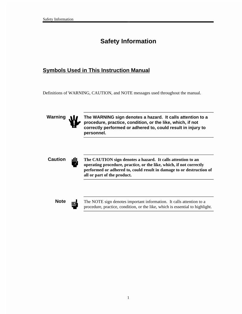
Symbols Used in This Instruction Manual
Definitions of WARNING, CAUTION, and NOTE messages used throughout the manual.
Warning The WARNING sign denotes a hazard. It calls attention to aprocedure, practice, condition, or the like, which, if notcorrectly performed or adhered to, could result in injury topersonnel.
Caution The CAUTION sign denotes a hazard. It calls attention to anoperating procedure, practice, or the like, which, if not correctlyperformed or adhered to, could result in damage to or destruction ofall or part of the product.
Note The NOTE sign denotes important information. It calls attention to aprocedure, practice, condition, or the like, which is essential to highlight.

Safety Information
2
Symbols Found on the Unit
The following table describes symbols that may be found on the unit.
Definition of Symbols Found on the Unit
|
On (Supply) IEC 417, No.5007
Off (Supply) IEC 417, No.5008
Earth (ground) IEC 417, No.5017
Protective earth (ground)
IEC 417, No.5019
Frame or chassis IEC 417, No.5020
Equipotentiality IEC 417, No.5021
Direct current IEC 417, No.5031
Alternating Current IEC 417, No. 5032
Both direct and alternating Current
IEC 417, No.5033-aClass ll equipment
IEC 417, No.5172-a
Three phase alternating Current
IEC 617-2 No. 020206
Caution, refer to accompanying
documents ISO 3864, No. B.3.1
Caution, risk of electric shock
ISO 3864, No. B.3.6Caution, hot surface IEC 417, No. 5041
Table 1: Definition of Symbols Found on the Unit

Safety Information
3
Safety Procedures and Precautions
The following general safety precautions must be observed during all phases of operation of thisinstrument. Failure to comply with these precautions or with specific warnings elsewhere inthis manual violates safety standards of intended use of the instrument and may impair theprotection provided by the equipment. MKS Instruments, Inc. assumes no liability for thecustomer’s failure to comply with these requirements.
DO NOT SUBSTITUTE PARTS OR MODIFY INSTRUMENT
Do not install substitute parts or perform any unauthorized modification to the instrument.Return the instrument to an MKS Calibration and Service Center for service and repair to ensurethat all safety features are maintained.
SERVICE BY QUALIFIED PERSONNEL ONLY
Operating personnel must not remove instrument covers. Component replacement and internaladjustments must be made by qualified service personnel only.
GROUNDING THE PRODUCT
This product is grounded through the grounding conductor of the power cord. To avoid electricalshock, plug the power cord into a properly wired receptacle before connecting it to the productinput or output terminals. A protective ground connection by way of the grounding conductor inthe power cord is essential for safe operation.
DANGER ARISING FROM LOSS OF GROUND
Upon loss of the protective-ground connection, all accessible conductive parts (including knobsand controls that may appear to be insulating) can render an electrical shock.
GROUND AND USE PROPER ELECTRICAL FITTINGS
Dangerous voltages are contained within this instrument. All electrical fittings and cables mustbe of the type specified, and in good condition. All electrical fittings must be properly connectedand grounded.
USE THE PROPER POWER CORD
Use only a power cord that is in good condition and which meets the input power requirementsspecified in the manual.
Use only a detachable cord set with conductors that have a cross-sectional area equal to or greaterthan 0.75 mm2. The power cable should be approved by a qualified agency such as VDE,Semko, or SEV.

Safety Information
4
USE THE PROPER POWER SOURCE
This product is intended to operate from a power source that does not apply more voltagebetween the supply conductors, or between either of the supply conductors and ground, than thatspecified in the manual.
USE THE PROPER FUSE
Use only a fuse of the correct type, voltage rating, and current rating, as specified for yourproduct.
DO NOT OPERATE IN EXPLOSIVE ATMOSPHERES
To avoid explosion, do not operate this product in an explosive environment unless it has beenspecifically certified for such operation.
HIGH VOLTAGE DANGER
High voltage is present in the cable and the sensor when the controller is turned on.
Chapter One: General Information Introduction
5
Chapter One: General Information
Introduction
The MKS Type 250E Pressure/Flow Controller will control any one of a variety of flow valves toaccurately maintain a set pressure or flow. The 250 controller can provide a ±15 VDC outputand accepts inputs from a variety of pressure transducers and mass flow meters. Two controllerscan be combined to provide two gas ratio control. The front panel controls allow selection of theinput range, control loop tuning, and automatic and manual valve control. An error meter isprovided on standard units to assist you in tuning the control loop. External signals cancommand the external set point, close the valve, or switch to the manual control. A DVM optionis available to provide 4½ place display of the control variable.
Typically, a pressure control system consists of three basic parts:
• The pressure sensor
• The controller and control valve
• The system whose pressure is to be controlled
The pressure sensor will usually be an MKS Baratron® Capacitance Manometer with an output of0 to 10 VDC. Provision for other outputs (0 to 1 VDC or 0 to 100 mV) has been built into thecontroller so that other transducers may be used. The pressure (vacuum) system will consist of achamber and a pumping system. Typically, users want to control the flow of gas entering thesystem while the system pressure is maintained by the 250 controller and a control valve.
The controller’s new 9-pin Type “D” connector allows you to connect the unit to a variety ofcontrol valves (refer to Table 3, page 16). If you install the 250 controller into an existingsystem that uses the old (hex) connector cables, an adapter cable is required (refer to ValveConnector, page 20, for more information.
Introduction Chapter One: General Information
6
In more elaborate systems, the chamber pressure may be controlled with one controller while aknown mass flow is admitted with the aid of a laminar flow element and its separate controller.The 250 controller takes the DC pressure signal, compares it to the set point, and positions thevalve so that it drives the actual pressure to the set pressure. The 250 controller contains thethree modes of control action found in most industrial controllers: proportional, derivative, andintegral. Briefly, these functions are as follows:
1. Proportional gives a valve action (position) that is instantaneously a linear function ofthe error signal. For example:
Signal to valve = K1 x Error (K1 is adjustable by the gain pot)
2. Derivative action provides a signal to the valve that is proportional to the rate of changeof the error signal. For example:
Signal to valve = K2 x d Error (K2 is adjustable by the phase pot)dt
A simple description of this mode of control is that it provides an anticipation element,or the valve reaches its proper steady state position sooner than without derivative. Thisis apparent when setting up a system; the derivative or phase lead control tailors theunder or overshoot. In other words, it cancels out the build-up of lags already built intothe system.
3. Integral action provides an additional valve signal which is proportional to the length oftime that an error signal exists. For example:
Signal to valve = ∫ d Error / dt
In other words, as time passes, the valve position changes which reduces the error signalto zero.
Note The 250 controller has the integral and proportional control adjustmentscombined into one front panel GAIN pot.

Chapter One: General Information How This Manual is Organized
7
How This Manual is Organized
This manual is designed to provide instructions on how to set up, install, and operate a Type 250unit.
Before installing your Type 250 unit in a system and/or operating it, carefully read andfamiliarize yourself with all precautionary notes in the Safety Messages and Proceduressection at the front of this manual. In addition, observe and obey all WARNING andCAUTION notes provided throughout the manual.
Chapter One, General Information, (this chapter) introduces the product and describes theorganization of the manual.
Chapter Two, Installation, explains the environmental requirements and describes how to mountthe instrument in your system.
Chapter Three, Overview, gives a brief description of the instrument and its functionality.
Chapter Four, Operation, describes how to use the instrument and explains all the functions andfeatures.
Chapter Five, Maintenance and Troubleshooting, lists any maintenance required to keep theinstrument in good working condition, and provides a checklist for reference should theinstrument malfunction.
Appendix A, Product Specifications, lists the specifications of the instrument.
Appendix B, Model Code Explanation, describes the instrument’s ordering code.
Customer Support
Standard maintenance and repair services are available at all of our regional MKS Calibrationand Service Centers, listed on the back cover. In addition, MKS accepts the instruments of othermanufacturers for recalibration using the Primary and Transfer Standard calibration equipmentlocated at all of our regional service centers. Should any difficulties arise in the use of your Type250 instrument, or to obtain information about companion products MKS offers, contact anyauthorized MKS Calibration and Service Center. If it is necessary to return the instrument toMKS, please obtain an ERA Number (Equipment Return Authorization Number) from the MKSCalibration and Service Center before shipping. The ERA Number expedites handling andensures proper servicing of your instrument.
Please refer to the inside of the back cover of this manual for a list of MKS Calibration andService Centers.
Warning All returns to MKS Instruments must be free of harmful,corrosive, radioactive, or toxic materials.

Customer Support Chapter One: General Information
8
This page intentionally left blank.

Chapter Two: Installation How To Unpack the Type 250 Unit
9
Chapter Two: Installation
How To Unpack the Type 250 Unit
MKS has carefully packed the Type 250 unit so that it will reach you in perfect operating order.Upon receiving the unit, however, you should check for defects, cracks, broken connectors, etc.,to be certain that damage has not occurred during shipment.
Note Do not discard any packing materials until you have completed yourinspection and are sure the unit arrived safely.
If you find any damage, notify your carrier and MKS immediately. If it is necessary to return theunit to MKS, obtain an ERA Number (Equipment Return Authorization Number) from the MKSService Center before shipping. Please refer to the inside of the back cover of this manual for alist of MKS Calibration and Service Centers.
Caution Only qualified individuals should perform the installation and anyuser adjustments. They must comply with all the necessary ESD andhandling precautions while installing and adjusting the instrument.Proper handling is essential when working with all highly sensitiveprecision electronic instruments.
Unpacking Checklist
Standard Equipment
• Type 250 Unit
• Type 250 Instruction Manual (this book)
• Power Cable
Optional Equipment
• Rack Mounting Kit:RM-6
• Electrical Connector Accessory Kit:250E-K1 (includes an I/O connector for the rear panel of the unit, a cover for the
I/O connector, and a screw lock assembly for the I/O connector cover)
• System Interface Cables (refer to Table 2, page 10)

Interface Cables Chapter Two: Installation
10
Interface Cables
As of January 1, 1996, most products shipped to the European Community must comply with theEMC Directive 89/336/EEC, which covers radio frequency emissions and immunity tests. Inaddition, as of January 1, 1997, some products shipped to the European Community must alsocomply with the Product Safety Directive 92/59/EEC and Low-Voltage Directive 73/23/EEC,which cover general safety practices for design and workmanship. MKS products that meetthese requirements are identified by application of the CE Mark.
To ensure compliance with EMC Directive 89/336/EEC, an overall metal braided shielded cable,properly grounded at both ends, is required during use. No additional installation requirementsare necessary to ensure compliance with Directives 92/59/EEC and 73/23/EEC.
Note 1. Overall metal braided shielded cables, properly grounded at bothends, are required during use to meet CE Mark specifications.
2. To order metal braided, shielded cables, add an “S” after the cabletype designation. For example, to order a standard cable to connectthe 250 unit to a Type 627 transducer, use part number CB258-1-10;for a metal braided, shielded cable, use part number CB258S-1-10.
System Interface Cables
The system interface cables include cables to connect the 250 controller to a transducer or to avalve, as well as the adapter cable necessary to replace a 250A-C unit with a 250E unit.
System Interface Cables
To Connect the 250 Unit To... Use the MKS Cable...
Standard Shielded
270/690 system CB250-7-3 CB250S-7-3
122, 124, 223, 622, and 623 transducers CB254-2-10 CB254S-2-10
221 transducer CB254-1-10 CB254S-1-10
220 transducer CB254-10-10 CB254S-10-10
127, 624, 626, 627 transducers and 179, 258, 358,558 mass flow meters
CB258-1-10 CB258S-1-10
128, 625, and 628 transducers CB128-2-10 CB128S-2-10
PDR-C-1C/2C, PDR-D-1, and PDR-5B powersupply/readouts
CB254-17-6 CB254S-17-6
120 transducer with a separate power connector CB120-3-10 CB120S-3-10
Table 2: System Interface Cables(Continued on next page)
Chapter Two: Installation Interface Cables
11
System Interface Cables (Continued)
To Connect the 250 Unit To... Use the MKS Cable...
Standard Shielded
148, 148J, 154, 248 valves CB251-2-10 CB251S-2-10
153 PCS CB153-2-10 CB153S-2-10
Allows replacement of a 250A-C unit with a 250E unit(refer to Valve Connector, page 20)
CB250-12-1 CB250S-12-1
Table 2: System Interface Cables
Generic Shielded Cable Description
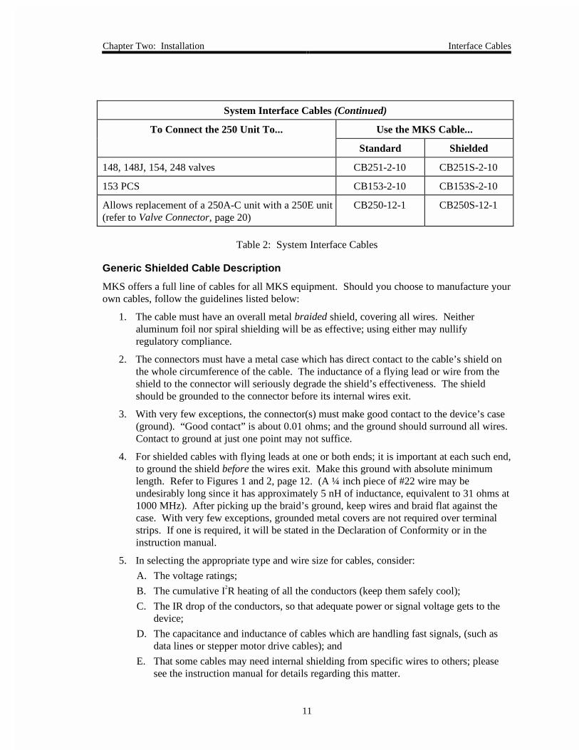
MKS offers a full line of cables for all MKS equipment. Should you choose to manufacture yourown cables, follow the guidelines listed below:
1. The cable must have an overall metal braided shield, covering all wires. Neitheraluminum foil nor spiral shielding will be as effective; using either may nullifyregulatory compliance.
2. The connectors must have a metal case which has direct contact to the cable’s shield onthe whole circumference of the cable. The inductance of a flying lead or wire from theshield to the connector will seriously degrade the shield’s effectiveness. The shieldshould be grounded to the connector before its internal wires exit.
3. With very few exceptions, the connector(s) must make good contact to the device’s case(ground). “Good contact” is about 0.01 ohms; and the ground should surround all wires.Contact to ground at just one point may not suffice.
4. For shielded cables with flying leads at one or both ends; it is important at each such end,to ground the shield before the wires exit. Make this ground with absolute minimumlength. Refer to Figures 1 and 2, page 12. (A ¼ inch piece of #22 wire may beundesirably long since it has approximately 5 nH of inductance, equivalent to 31 ohms at1000 MHz). After picking up the braid’s ground, keep wires and braid flat against thecase. With very few exceptions, grounded metal covers are not required over terminalstrips. If one is required, it will be stated in the Declaration of Conformity or in theinstruction manual.
5. In selecting the appropriate type and wire size for cables, consider:
A. The voltage ratings;
B. The cumulative I2R heating of all the conductors (keep them safely cool);
C. The IR drop of the conductors, so that adequate power or signal voltage gets to thedevice;
D. The capacitance and inductance of cables which are handling fast signals, (such asdata lines or stepper motor drive cables); and
E. That some cables may need internal shielding from specific wires to others; pleasesee the instruction manual for details regarding this matter.
Interface Cables Chapter Two: Installation
12
Example 1: Preferred Method To Connect Cable(shown on a transducer)
Transducer
Overall Insulation(if present)
Bare Metal Cable ClampMaking Firm Contact To Braid
Braid Here Is Desirable(but not usually necessary)
Keep Wires and BraidFlat Against Case
Metal Cable Clamp
Screw
Split Lock Washer
External Tooth Lock Washer
Transducer Housing
Optional Plastic or Metal CableClamp (For Physical Strain Relief)
Figure 1: Preferred Method To Connect a Shielded Cable
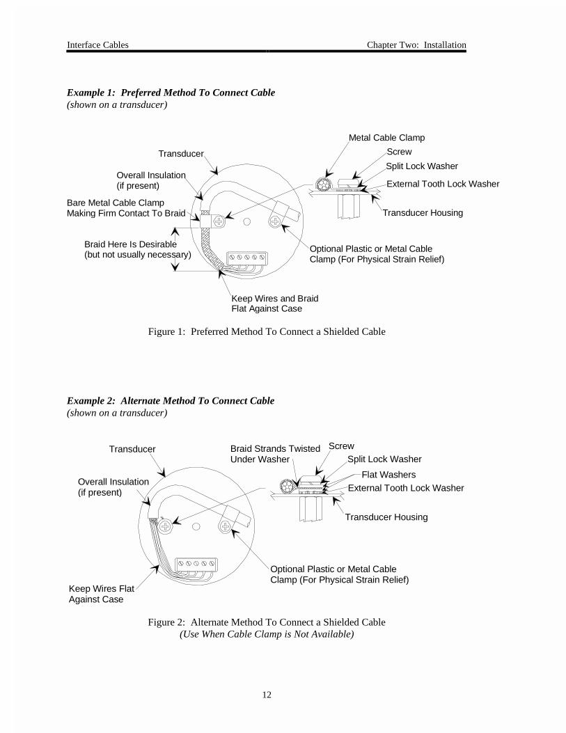
Example 2: Alternate Method To Connect Cable(shown on a transducer)
Transducer
Overall Insulation(if present)
Braid Strands TwistedUnder Washer
Keep Wires Flat Against Case
Optional Plastic or Metal CableClamp (For Physical Strain Relief)
ScrewSplit Lock Washer
Flat WashersExternal Tooth Lock Washer
Transducer Housing
Figure 2: Alternate Method To Connect a Shielded Cable(Use When Cable Clamp is Not Available)

Chapter Two: Installation Product Location and Requirements
13
Product Location and Requirements
The Type 250 unit meets the following criteria:
• POLLUTION DEGREE 2 in accordance with IEC 664
• Transient overvoltages according to INSTALLATION CATEGORY II
Operating Environmental Requirements
• Ambient Operating Temperature: 0° to 40° C (32° to 104° F)
• Main supply voltage fluctuations must not exceed ±10% of the nominal voltage
• Ventilation requirements include sufficient air circulation
• Connect the power cord into a grounded outlet
• Power: 100 to 120 VAC nominal @ 50/60 Hz220 to 240 VAC nominal @ 50/60 Hz
50 VA maximum (50/60 Hz)
Safety Conditions
The 250 unit poses no safety risk under the following environmental conditions.
• Altitude: up to 2000 m
• Maximum relative humidity: 80% for temperatures up to 31° C, decreasing linearly to 50% at 40° C
Setup Chapter Two: Installation
14
Setup
System Design
There are several considerations that must be dealt with before start-up:
Valve Selection
The correct valve must be selected to allow a reasonable fast time response.
For example:
Assume a system whose pumping speed is 150 liters/sec. and whose volume is 100 liters. Thismeans that the pump down time constant (T.C.) will be 0.7 seconds. To control at 100µ, or 0.1Torr, with an up time constant equal to the down time constant (in the practical case this willrarely happen), the quantity of gas that the pump is able to draw out at this pressure is 150liters/sec. x 100µ, or 15000µ L/sec. Converting this to sccm: = 1184.
If the 1000 sccm valve is chosen, it will never get up to 100µ because the pump is slightly fasterthan the valve (at 100µ). The valve goes wide open and the pressure drops to the point where thevalve throughput equals that of the pump (somewhat less than 100µ pressure). Two things canbe done to make the system work.
The first, and proper course of action (which maintains the system’s natural fast response), is toselect a bigger valve (2000 sccm) which provides more gas than the pump can extract. Ifovershoot occurs, the down T.C. will be a combination of the pump and chamber T.C., modifiedby the controller’s T.C. as control point is approached. Basically, if a large valve is selected, thespeed-up control will be a function of the controller’s speed (incoming flow); the down controlwill be a function of the pump’s speed.
The second course of action is to reduce the pumping speed. However, this approach (usuallyrealized by partially closing a valve) slows down the entire system.
Pressure Range
The range of pressures over which the system will work must be selected.
It is recommended that this be limited to 100 to 1; although pressures five decades apart havebeen controlled with a single valve.
Chapter Two: Installation Setup
15
Lags
Lags must be removed.
If lags (delays) are built into a system, stabilization will be difficult or impossible. Lag may beintroduced pneumatically in two areas: the tubing to the sensor and the tubing to the valve. Bothtubing runs must be less than 6 inches long and no less than ¼ inch in diameter. Make surethe fittings do not introduce extra lags (internal small drilled passages). Other lags such asantichambers off the main vacuum chamber may also cause problems and must be kept to aminimum.
If a 270/690 type system is used for pressure measurement, the most likely cause of lags isallowing the indicator switch on the 270 signal conditioner to be placed in the wrong position.This switch must be in the NORMAL position.
Choking
Another important consideration, is a condition that is peculiar to diffusion pumps, calledchoking. If too much gas is introduced at too high a pressure, the pumping speed becomeserratic and changes radically. This behavior is easily recognized by lack of stability andpneumatic noise, sometimes making control impossible. Reducing the flow to the pump is theonly solution.
Note Diffusion pumps should never be operated at inlet pressures above whichthe “top jet” will experience a pressure in excess of 5 x 10⁻⁴ Torr.

Setup Chapter Two: Installation
16
Mounting Instructions
Controller
The 250 can be mounted on any instrument panel or placed on a bench. The mounting positionis not critical and it will operate properly in any position. While the unit is designed and testedto operate with no air circulation, it will run much cooler if the top air slots are clear to allowconvection air circulation. No special precautions are needed to protect the unit from ordinarymechanical shock and vibration. A rack mounting kit (RM-6) is available from MKS for singleor dual unit rack mounting.
Valve
The 250 unit can control a variety of valves, as listed in Table 3. The control valve should beconnected to the 250 controller using piping or hose as large in diameter and as short in length aspossible. The valve can be changed at any time as long as the proper cable is used. Refer to theappropriate manual for mounting instructions.
Control Valves
Type ofValve
Manufacturer ManufacturerPart Number
MKS PartNumber
Flow Range(sccm)
ConnectionCable or
Connector
Piezoelectric Veeco PV-10 170M-49 0 - 200 Consultfactory
Solenoid MKS 148, 148J,154, 248
148, 148J,154, 248
0 - 10 to0 - 50K
CB-251-2-10
Solenoid Brooks 5835A 251-xx 0 - 50K Consultfactory
Solenoid Balzers RME010 255 0 - 40K Consultfactory
Table 3: Control Valves
Chapter Two: Installation Setup
17
Transducer
Any pressure transducer which delivers at least 0.1 Volt full scale, can be used as the feedbackelement for total pressure control (refer to Optional Equipment, page 9).
The pressure transducer should be mounted so that it is firmly supported, while at the same time,isolated from any vibration.
Mass Flow Meters
Any mass flow meter (MFM) which delivers at least 5 Volt full scale can be used with the 250controller depending on the flow rates, types of gas, etc. needed in the control system (refer toOptional Equipment, page 9). Refer to the appropriate MFM manual for mounting instructions.
Interconnections
Figures 3 and 4, page 18, show typical piping and cable interconnection diagrams. Figure showsthe usual setup for standard pressure control. Figure 4 shows a setup for multi-gas ratio control.
Connect the valve and sensor to the chamber using short connections with minimum restrictions.Six inches of ¼” tubing should be maximum. Never reduce the tubing size below that of thevalve and transducer.
Connect the valve and transducer to the back of the controller and set the valve mode switch(CMAE) to CLOSE (refer to Rear Panel Controls, page 26).
Setup Chapter Two: Installation
18
Figure 3: Standard Pressure Control Setup
Figure 4: Multi-Gas Ratio Control

Chapter Two: Installation Electrical Information
19
Electrical Information
Fuses
The line fuses protect the internal circuitry; both sides of the line are fused. The fuse values arelisted in Table 4.
Fuse Information
Voltage Fuse Type
115 VAC 0.50 A (T) / 250 V / 5 x 20 mm
230 VAC 0.25 A (T) / 250 V / 5 x 20 mm
Table 4: Fuse Information
Caution Disconnect the line cord from the AC power outlet before replacingthe fuse.
Grounding
For protective earthing, plug the power cord into a properly grounded outlet.
Electrical Information Chapter Two: Installation
20
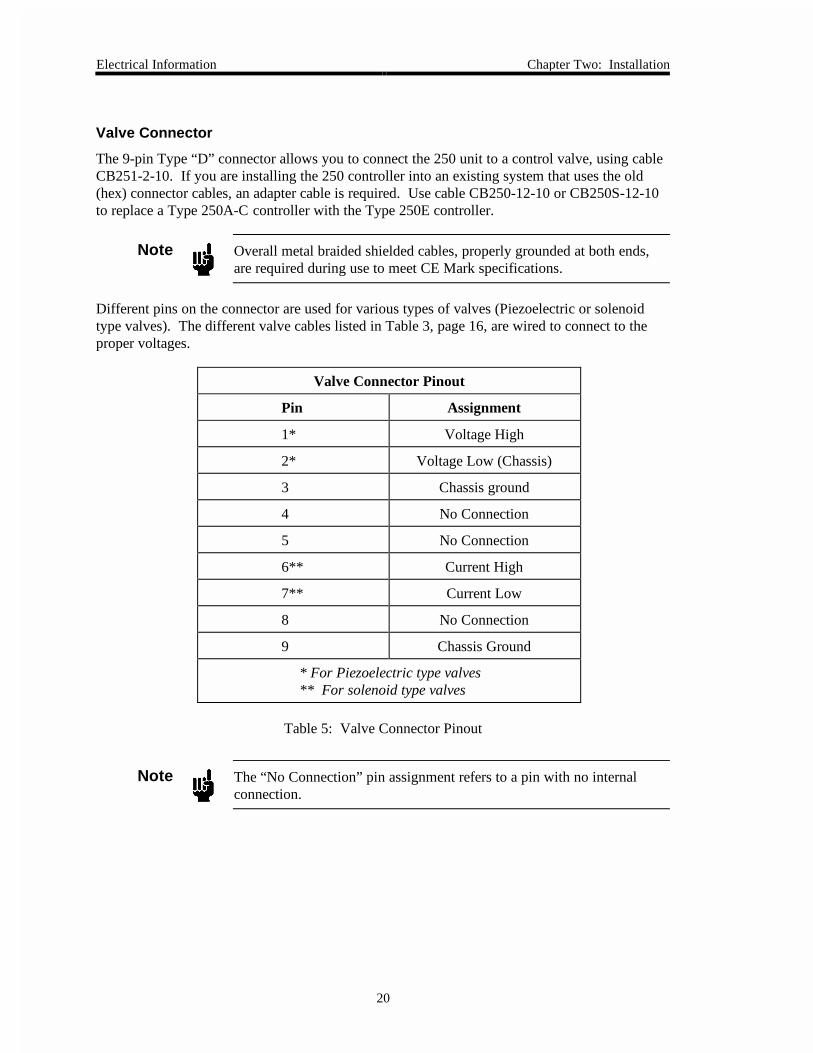
Valve Connector
The 9-pin Type “D” connector allows you to connect the 250 unit to a control valve, using cableCB251-2-10. If you are installing the 250 controller into an existing system that uses the old(hex) connector cables, an adapter cable is required. Use cable CB250-12-10 or CB250S-12-10to replace a Type 250A-C controller with the Type 250E controller.
Note Overall metal braided shielded cables, properly grounded at both ends,are required during use to meet CE Mark specifications.
Different pins on the connector are used for various types of valves (Piezoelectric or solenoidtype valves). The different valve cables listed in Table 3, page 16, are wired to connect to theproper voltages.
Valve Connector Pinout
Pin Assignment
1* Voltage High
2* Voltage Low (Chassis)
3 Chassis ground
4 No Connection
5 No Connection
6** Current High
7** Current Low
8 No Connection
9 Chassis Ground
* For Piezoelectric type valves** For solenoid type valves
Table 5: Valve Connector Pinout
Note The “No Connection” pin assignment refers to a pin with no internalconnection.
Chapter Two: Installation Electrical Information
21
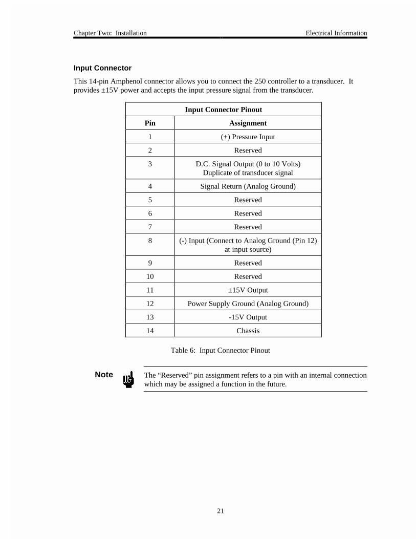
Input Connector
This 14-pin Amphenol connector allows you to connect the 250 controller to a transducer. Itprovides ±15V power and accepts the input pressure signal from the transducer.
Input Connector Pinout
Pin Assignment
1 (+) Pressure Input
2 Reserved
3 D.C. Signal Output (0 to 10 Volts)Duplicate of transducer signal
4 Signal Return (Analog Ground)
5 Reserved
6 Reserved
7 Reserved
8 (-) Input (Connect to Analog Ground (Pin 12)at input source)
9 Reserved
10 Reserved
11 ±15V Output
12 Power Supply Ground (Analog Ground)
13 -15V Output
14 Chassis
Table 6: Input Connector Pinout
Note The “Reserved” pin assignment refers to a pin with an internal connectionwhich may be assigned a function in the future.
Electrical Information Chapter Two: Installation
22
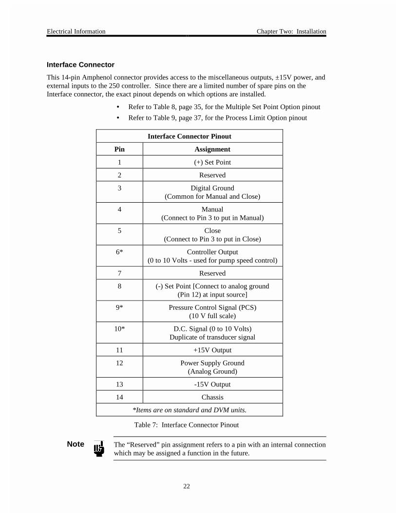
Interface Connector
This 14-pin Amphenol connector provides access to the miscellaneous outputs, ±15V power, andexternal inputs to the 250 controller. Since there are a limited number of spare pins on theInterface connector, the exact pinout depends on which options are installed.
• Refer to Table 8, page 35, for the Multiple Set Point Option pinout
• Refer to Table 9, page 37, for the Process Limit Option pinout
Interface Connector Pinout
Pin Assignment
1 (+) Set Point
2 Reserved
3 Digital Ground(Common for Manual and Close)
4 Manual(Connect to Pin 3 to put in Manual)
5 Close(Connect to Pin 3 to put in Close)
6* Controller Output(0 to 10 Volts - used for pump speed control)
7 Reserved
8 (-) Set Point [Connect to analog ground(Pin 12) at input source]
9* Pressure Control Signal (PCS)(10 V full scale)
10* D.C. Signal (0 to 10 Volts)Duplicate of transducer signal
11 +15V Output
12 Power Supply Ground(Analog Ground)
13 -15V Output
14 Chassis
*Items are on standard and DVM units.
Table 7: Interface Connector Pinout
Note The “Reserved” pin assignment refers to a pin with an internal connectionwhich may be assigned a function in the future.
Chapter Three: Overview General Information
23
Chapter Three: Overview
General Information
The Type 250 controller is a versatile controller capable of pressure, flow, or flow ratio control.It is used for pressure control when a pressure transducer provides the feedback signal, and flowcontrol when a mass flow meter provides the feedback. If a second mass flow meter is used forexternal set point, flow ratio is controlled.
The purpose of a controller is to compare the required pressure level (set point) with the actualpressure level (feedback input) and make appropriate corrections in the pump speed (viaadjustments on the valve) until the actual pressure equals the required pressure.
Figure 3, page 18, shows a simple pressure control loop consisting of an input signal, controlleroutput valve, vacuum system, and pressure transducer. The pressure transducer converts pressureto an electrical signal which is compared in the controller to the required signal (in most cases, aprecision pot whose voltage is changed by rotating the dial). Note that in a simple pressure loop,the flow rate is not measured because it is unnecessary.
Any error between the actual (feedback) and required (set point) signals is amplified by thecontroller and fed to the valve. For example, if the pressure is higher than the set point, thecontroller reduces the current to the valve, which reduces the flow into the vacuum system,subsequently reducing the pressure.
An additional requirement of the controller is to provide a stabilizing or tuning control. Thiscontrol (PHASE LEAD) allows you to compensate for the different delays, or lags, that occur invarious systems.
Multi-Gas Ratio Control
When controlling multiple gases, the 250 unit operates in a similar manner to the single gassystem, except that a 0 to 10 Volt Pressure Control Signal (PCS) from the 250 controller is usedto control the set point signals to multiple mass flow controllers (MFC).
As in single gas systems, if the pressure is below the set point, the controller increases the PCSwhich increases all flows in a predetermined ratio. The exact ratio of the flow is determinedusing a power supply/display unit such as the 247, 647, or multiple 246 units.
Front Panel Controls Chapter Three: Overview
24
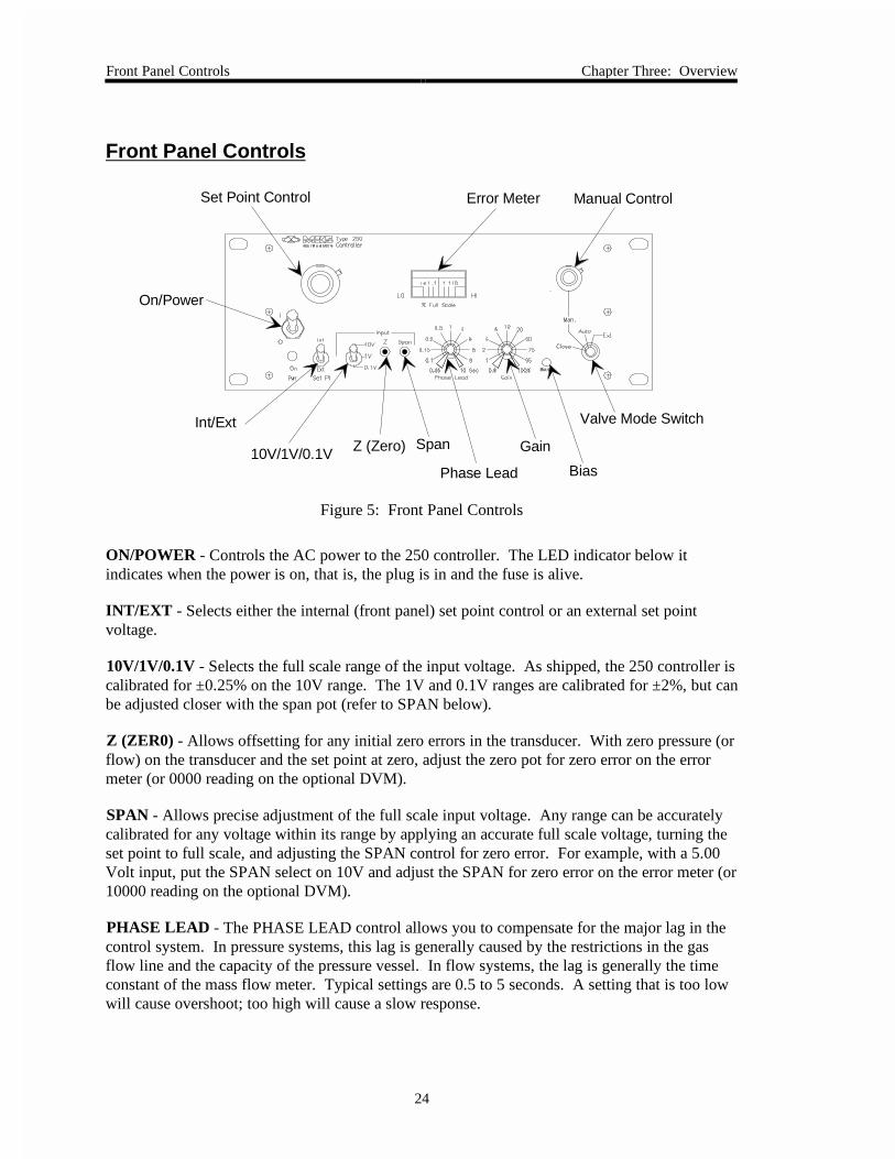
Front Panel Controls
On/Power
Int/Ext
Span10V/1V/0.1V
Phase Lead
Gain
Valve Mode Switch
Error MeterSet Point Control
Z (Zero)
Bias
Bias
Manual Control
Figure 5: Front Panel Controls
ON/POWER - Controls the AC power to the 250 controller. The LED indicator below itindicates when the power is on, that is, the plug is in and the fuse is alive.
INT/EXT - Selects either the internal (front panel) set point control or an external set pointvoltage.
10V/1V/0.1V - Selects the full scale range of the input voltage. As shipped, the 250 controller iscalibrated for ±0.25% on the 10V range. The 1V and 0.1V ranges are calibrated for ±2%, but canbe adjusted closer with the span pot (refer to SPAN below).
Z (ZER0) - Allows offsetting for any initial zero errors in the transducer. With zero pressure (orflow) on the transducer and the set point at zero, adjust the zero pot for zero error on the errormeter (or 0000 reading on the optional DVM).
SPAN - Allows precise adjustment of the full scale input voltage. Any range can be accuratelycalibrated for any voltage within its range by applying an accurate full scale voltage, turning theset point to full scale, and adjusting the SPAN control for zero error. For example, with a 5.00Volt input, put the SPAN select on 10V and adjust the SPAN for zero error on the error meter (or10000 reading on the optional DVM).
PHASE LEAD - The PHASE LEAD control allows you to compensate for the major lag in thecontrol system. In pressure systems, this lag is generally caused by the restrictions in the gasflow line and the capacity of the pressure vessel. In flow systems, the lag is generally the timeconstant of the mass flow meter. Typical settings are 0.5 to 5 seconds. A setting that is too lowwill cause overshoot; too high will cause a slow response.

Chapter Three: Overview Front Panel Controls
25
GAIN - The GAIN setting determines the overall gain of the controller and should be as high aspossible without making the system unstable. The higher the gain, the smaller the dead band. Ifsome overshoot is tolerable, better control (less dead band) can be achieved. Typical settings are20 to 50%.
BIAS - The BIAS control adjusts the minimum voltage or current applied to the valve in theAUTO, EXT, and MANUAL positions. Proper adjustment of the bias will improve the settlingtime at initial turn-on, and reduce undershooting during oscillations or large changes in flow(refer to How To Use the Bias Control, page 31).
VALVE MODE SWITCH - The VALVE MODE SWITCH selects the method of valve control.In CLOSE, all signal is removed from the valve. The MANUAL control determines the valvesignal (voltage or current). In AUTO, the controller drives the valve according to the error signaland the phase and gain controls. In EXT, the controller is in automatic unless one of the externalcontrol lines (MANUAL or CLOSE) is connected to digital ground. If both MANUAL andCLOSE are connected to digital ground, the “Close” operation will dominate. Externalcommands will not affect the 250 controller unless the CMAE switch is in the EXT position.
MANUAL - The MANUAL control allows you to control the valve signal (voltage or current)directly, without worrying about set point setting, process variables, etc. Note that with mostvalves, the flow output is not proportional to valve signal.
A signal of from 40 to 90% is needed to start the valve opening and it will be completely openwith an additional 10%.
ERROR METER - Meter indication of the difference between the set point and the actualpressure, or flow. The ERROR METER is useful when tuning the PHASE or GAIN controlsbecause it shows overshoot and oscillation around the proper control level.
The ERROR METER is not provided on controllers with the DVM option.
SET POINT - The SET POINT control is your input to the 250 controller. The dial representsthe fraction of the full scale pressure range. The SET POINT is set to the desired pressure, orflow, and the controller maintains that pressure while in the AUTO or EXT mode. For example,if the transducer’s full scale pressure is 1 Torr and the SET POINT is set for 0.432 (4/32indicated on the dial), then the 250 controller maintains a pressure of 432 microns. The 1V rangecan be used to increase the resolution at the lower 10% of a 10V range. In the example above, ifthe 1V range is used (100 microns full scale), the controller maintains 43.2 microns.
When operating with external set point input (0 to 5V), the front panel SET POINT controlshould be fully clockwise (CW).

Rear Panel Controls Chapter Three: Overview
26
Rear Panel ControlsInput Connector
Interface Connector
Valve Connector
Fuse Line Cord
Voltage Selector
100-120V - 0.50A(T)220-240V - 0.25A(T)
100/115V - 120V220/230V - 240V40 VA MaxValve Output
Max. Voltage100VDC, 1 mA
Fuses: 250V IEC
Line 50/60 Hz
Figure 6: Rear Panel Controls
LINE CORD - Provides 115 or 230 VAC to the 250 controller. For protective earthing, plug thepower cord into a properly grounded outlet.
VOLTAGE SELECTOR - Should be set to the proper input voltage before the line cord isplugged in and the power turned ON.
FUSE - Line fuse to protect internal circuitry. Both sides of the line is fused.
Caution Disconnect line cord from the AC power outlet before replacing thefuse.
VALVE - The control valve connects to the 250 controller through a 9-pin female Type “D”connector. Use cable CB251-2-10 to connect the valve to the controller. Different pins on theconnector are used for various types of valves. The different valve cables are wired to connect tothe proper voltages.
Note If you are installing the 250E controller into an existing system that usesthe old (hex) connector cables, an adapter cable is required. Use adaptercable CB250-12-1 or CB250S-12-1 to replace a Type 250A-C controllerwith the Type 250E controller. Refer to Table 5, page 20, for the Valveconnector pinout.
INTERFACE - This 14-pin Amphenol connector provides access to the miscellaneous outputs,±15V power, and external inputs to the controller. Refer to Table 7, page 22, for the Interfaceconnector pinout.
INPUT - This 14-pin Amphenol connector provides ±15V power and accepts the input pressuresignal. Refer to Table 6, page 21, for the Input connector pinout.
Chapter Three: Overview Labels
27
Labels
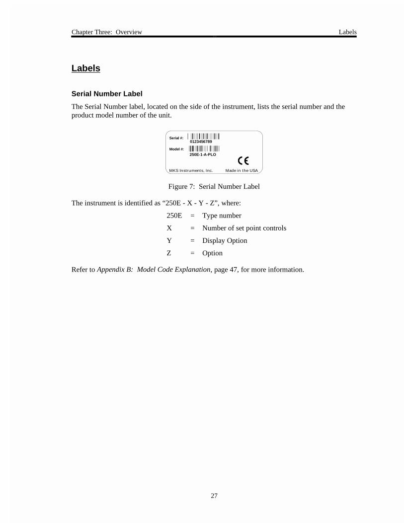
Serial Number Label
The Serial Number label, located on the side of the instrument, lists the serial number and theproduct model number of the unit.
250E-1-A-PLO
Serial #:
Model #:
0123456789
MKS Instruments, Inc. Made in the USA
Figure 7: Serial Number Label
The instrument is identified as “250E - X - Y - Z”, where:
250E = Type number
X = Number of set point controls
Y = Display Option
Z = Option
Refer to Appendix B: Model Code Explanation, page 47, for more information.

Labels Chapter Three: Overview
28
This page intentionally left blank.
Chapter Four: Operation How To Setup the Controller
29
Chapter Four: Operation
How To Setup the Controller
Before plugging in the AC line cord, turn the power switch OFF and perform the following steps:
1. Ensure that the voltage selector on the rear panel is in the proper position and that thefuse has the proper rating.
The power and fuse ratings are listed in Appendix A: Product Specifications, page 45.
2. Place the INT/EXT and RANGE switches in the proper positions and turn the SETPOINT and MANUAL controls to zero.
3. Plug in the power cord and turn on the POWER.
The power LED should light.
4. Allow the system to warm up for at least 15 minutes.
5. Ensure the chamber pressure is less than the resolution of the transducer, and zero thecontroller by setting the SET POINT at zero (fully CCW) and adjusting the ZEROcontrol for zero error on the meter (or adjust for 0000 reading on the optional DVM).
Note 1. Temperature-controlled transducers, such as the 270/690 and 127 or128 units, need approximately four hours to completely stabilize.
2. If a 270 signal conditioner is used, the 270 Sensor Zero control canbe used for zeroing; the RESPONSE switch should be in theNORMAL position.
6. Turn ON the gas source.

How To Use Manual Control Chapter Four: Operation
30
How To Use Manual Control
The 250 controller has a MANUAL control which, when properly adjusted, should make theinitial valve turn-on quick and easy.
Place the valve selector in MANUAL and increase the MANUAL control setting. During thefirst few turns nothing will happen to the flow (or pressure in the system). The numbers on theMANUAL control are meaningless except to allow the operator to return to a known position.
When the signal to the valve is large enough to exceed the valve offset, the valve begins opening.At this point you can fine-tune the MANUAL control to set a flow into the system to produce thedesired pressure. Leave the MANUAL control in the set position in order to produce thequickest and smoothest transition from CLOSE to AUTOMATIC.
How To Tune-Up the Controller
Turning the valve mode switch (CMAE) to AUTO puts the controller into action. If the SETPOINT control is set for the same pressure (or flow) that the MANUAL control had established,then the transition from MANUAL to AUTO should be smooth and bumpless.
To tune the controller, turn the GAIN up until 0.1% oscillations are apparent. Minimizeoscillation amplitude using PHASE LEAD settings. When oscillations cease, turn up the GAINand readjust the PHASE LEAD if necessary. Check the settings by changing the SET POINTcontrol. Optimum response is for the error to reduce to zero quickly, but with no overshoot. Ifthe pressure oscillates (error meter swings from positive to negative) the GAIN is too high. TheGAIN may be increased later when the PHASE LEAD is properly adjusted. If the pressureovershoots, but settles to the proper value, more PHASE LEAD is required. If the pressure isslow rising to the proper value, less PHASE LEAD is required. If the pressure settles at a steadyvalue, which is other than the set point (greater than ±0.25% error), more GAIN is needed.
When making final adjustments, move the controls less than 10° to prevent overcontrolling.Various pressures will require different settings of GAIN and PHASE LEAD although pressuresup to a decade apart may be controlled using the same settings. Speed will be sacrificed forlower pressures.
Note On controllers with the DVM option, the system error will have to becalculated by subtracting the set point value from the displayed value.
Chapter Four: Operation How To Use the Bias Control
31
How To Use the Bias Control
The BIAS control establishes a floor, or minimum, signal level to the valve which prevents theintegrator from “winding up” or going too far into saturation. The signal to the valve consists ofthe bias level plus the controller signal. In MANUAL, the controller signal is determined by theMANUAL control. In AUTO, the controller signal is determined by the error signal and theGAIN and PHASE LEAD controls.
For good control, it is important that the BIAS be set as high as possible, particularly duringpressure transients. The factory BIAS adjustment is for 35% of output.
If the controller cannot turn the valve completely off, the BIAS may be set too high. If the BIAScontrol needs adjustment, do the following:
1. Turn the MANUAL control to zero.
2. Turn the CMAE switch to CLOSE and check that there is no flow and the system can bepumped to zero pressure.
3. Turn the CMAE switch to MANUAL; there should still be no flow.
4. If there is flow, turn the BIAS control counterclockwise (CCW) until the flow stops andthen two more turns CCW.
5. If there is no flow, turn the BIAS control clockwise (CW) until flow just appears andthen back off (CCW) two turns.

How To Use the Normal/Reverse Switch Chapter Four: Operation
32
How To Use the Normal/Reverse Switch
Most applications will require that when the pressure (or flow) is greater than the set point, thevalve should have less drive to return the process to the proper value. This is “normal” operationand assumes that the output of the pressure (or flow) transducer increases positively forincreasing pressure (or flow).
Inside the 250 controller, at approximately the center of the P.C. board, is a slide switch whichcan be used to obtain “reverse” action from the controller.
This switch should be in the REVERSE position if either:
• The pressure (or flow) transducer output decreases for increasing pressure (or flow)
• The valve drive signal increases when the pressure (or flow) is greater than the set point(such as exhaust control)
How To Use External Control
The 250 unit can be externally controlled with two inputs on the Interface connector. Refer toTable 7, page 22, for the Interface connector pinout.
Note The front panel mode switch must be in the EXT position for the externalinputs to be accepted.
Shorting the CLOSE input (Pin 5) to digital ground (Pin 3) will cause all signals to be removedfrom the valve and it will close.
Shorting the MANUAL input (Pin 4) to digital ground (Pin 3) will put the controller in theManual mode. Whatever signal dialed into the Manual control, plus bias will be applied to thevalve.
Shorting both the CLOSE and MANUAL inputs to ground will put the controller in Close. IfPins 4 or 5 are not shorted to Pin 3, the 250 controller will provide automatic control of pressure(or flow) to the selected set point.
Chapter Four: Operation How To Use the DVM Option
33
How To Use the DVM Option
The 250 controller can optionally be supplied with a 4½ place DVM to display the controlledparameter (pressure or flow). The display is from 0000 to 10000 and the decimal point can bepositioned at any convenient location with switches inside the controller.
To check the calibration of the DVM, input 0.000 Volts at the Input connector and adjust theZERO control on the front panel for a reading of 0000 on the DVM. Make sure the Rangeswitch (10V, 1V, 0.1V) is in the proper position. If the full scale input is greater than 1 Volt,then the 10 V range must be used. Now apply full scale input voltage (typically 10 Volts or5 Volts) and adjust the front panel SPAN control for a reading that corresponds to the full scaleof the transducer.
For example, a pressure transducer where 10V = 1 Torr, input 10.00 Volts and adjust the SPANfor a reading of 10000. For a flow transducer where 5V = 200 sccm, input 5.00 Volts and adjustthe SPAN for 2000 (the set point pot is useable only over the lower 20%).
To select the decimal point, remove the top cover and locate the decimal point switch on themain P.C. board (labeled S7) near the power transformer. The switch is labeled for decimal pointlocations; only one should be ON at a time.
How To Use the Proportional Gain
In some unusual control applications, the two front panel controls GAIN and PHASE LEAD maynot provide enough adjustment to tune the control loop. A typical application is where thefeedback input is ion beam current rather than pressure or flow. In these applications, thePROPORTIONAL GAIN control inside the controller may provide enough additional controlrange to stabilize the loop.
The PROPORTIONAL GAIN control (R69) is a 25-turn trim pot on the right side as you look atthe front panel about half-way back on the main P.C. board. To try this control, turn it about 10turns clockwise and then tune the front panel controls (refer to How To Tune-Up the Controller,page 30). If this improves the loop stability and additional adjustment is desired, turn thePROPORTIONAL GAIN control several turns in each direction. The PROPORTIONAL GAINcontrol is very fine so several turns can be made without overcontrolling.
How To Use the Multiple Set Point Option Chapter Four: Operation
34
How To Use the Multiple Set Point Option
The Multiple Set Point Option (MSO) provides up to four front panel set point pots which can beselected either from the front panel, or remotely. When selected, each set point pot provides aprecision reference for the controller, which will maintain the control pressure (or flow) at thepreset level.
The set point pots are preset with up to four levels which can be selected by using the front panelselector switch. In the REMOTE position, fully close and a manual signal can be selected, andan external programmer can select any of the preset levels by activating a digital control line.
Settings
The MSO set point pots are 10-turn precision units with calibrated dials. Each pot covers the fullrange of the feedback transducer (0 to 100%). The controllers are calibrated for a precise 10 Voltfull scale and should not need adjustment if a 10 Volt transducer is used. If other full scalevoltage transducers are used, refer to the SPAN adjustment procedure, described in Front PanelControls, page 24.
The set point controls are your input to the controller. The dial represents the fraction of fullscale range. For example, if the transducer’s full scale pressure is 10 Torr, and a set point is setfor 0.342 (3/42 indicated on the dial), when the set point is selected, the controller will maintaina pressure of 3.42 Torr in either AUTO or EXT (with no overriding) commands.
Each set point pot should be set to a pressure (or flow) required by the process. The pots can beadjusted anytime, whether they are ON or OFF.
Selection
When the front panel switch selects a particular set point, all remote select signals are ignored.In REMOTE, all remote select signals are selected and it is important that only one set point beselected at a time.
As normally shipped, the remote set point select lines are wired for negative true; a short-to-digital ground will select the appropriate set point. When the lines are not shorted to ground, theyare pulled up to +5 V with a 10 K resistor.
If positive true logic is desired, that is, a positive signal (5V) will select the appropriate set point;then a jumper should be installed near R23 at the rear of the MSO P.C. board. Note that ifpositive true logic is used, all unused set point select lines must be held at digital ground.
As each set point is selected, a light above the set point pot is illuminated.

Chapter Four: Operation How To Use the Multiple Set Point Option
35
Interconnections
The remote set point select lines are brought out on the Interface connector, and are listed inTable 8. The digital ground should be connected to the circuit ground of the digital instrumentthat is selecting set points. Refer to Table 7, page 22, for the complete Interface connectorpinout.
Multiple Set Point Option Pinout
Interface Connector Pin Assignment
3 Digital Ground
6 Set Point 1
7 Set Point 2
9 Set Point 3
10 Set Point 4
Table 8: Multiple Set Point Option Pinout
Note The External Set Point Signal is not applicable on units with the MultipleSet Point Option. Also, the use of Pins 6, 9, and 10 for the MSOprecludes bringing out the Controller Output, Pressure Control Signal,and D.C. Signal.
How To Use the Process Limit Option Chapter Four: Operation
36
How To Use the Process Limit Option
The Process Limit Option (PLO) provides a logic signal (+5V) and relay closure when thecontroller error deviates from zero by more than the process limit. The process limit can be setby an internal control to any range from ±0.5 to ±100%. An LED indication is provided on theboard to assist in setup.
The PLO board compares the absolute value of the error signal to the process limit setting. If theerror is less than the setting, the relay is CLOSED, the LED is green, and the logic level is low(0 Volts). If the error signal is greater than the process limit setting, the relay is OPEN, the LEDis red, and the logic level is high (+5 Volts). If power is lost, the relay will open, the LED willbe off and the logic level will appear high.
Note For some customers, the logic output is reversed from that describedabove; within process control gives a high output (+5 Volts) andout-of-control gives a low output (0 Volts).
Controls
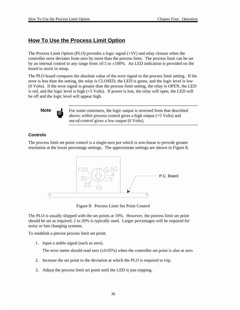
The process limit set point control is a single-turn pot which is non-linear to provide greaterresolution at the lower percentage settings. The approximate settings are shown in Figure 8.
P.C. Board
Figure 8: Process Limit Set Point Control
The PLO is usually shipped with the set points at 10%. However, the process limit set pointshould be set as required; 2 to 20% is typically used. Larger percentages will be required fornoisy or fast changing systems.
To establish a precise process limit set point:
1. Input a stable signal (such as zero).
The error meter should read zero (±0.05%) when the controller set point is also at zero.
2. Increase the set point to the deviation at which the PLO is required to trip.
3. Adjust the process limit set point until the LED is just tripping.
Chapter Four: Operation How To Use the Process Limit Option
37
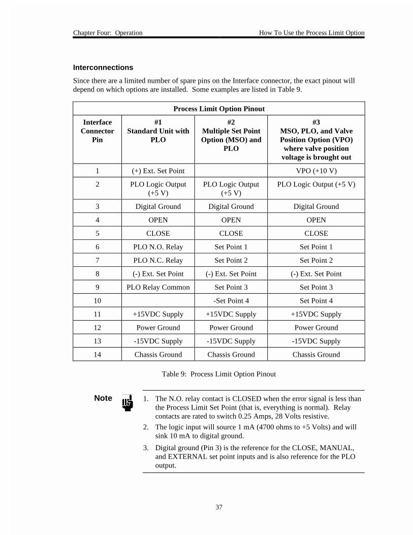
Interconnections
Since there are a limited number of spare pins on the Interface connector, the exact pinout willdepend on which options are installed. Some examples are listed in Table 9.
Process Limit Option Pinout
InterfaceConnector
Pin
#1Standard Unit with
PLO
#2Multiple Set PointOption (MSO) and
PLO
#3MSO, PLO, and ValvePosition Option (VPO)where valve position
voltage is brought out
1 (+) Ext. Set Point VPO (+10 V)
2 PLO Logic Output(+5 V)
PLO Logic Output(+5 V)
PLO Logic Output (+5 V)
3 Digital Ground Digital Ground Digital Ground
4 OPEN OPEN OPEN
5 CLOSE CLOSE CLOSE
6 PLO N.O. Relay Set Point 1 Set Point 1
7 PLO N.C. Relay Set Point 2 Set Point 2
8 (-) Ext. Set Point (-) Ext. Set Point (-) Ext. Set Point
9 PLO Relay Common Set Point 3 Set Point 3
10 -Set Point 4 Set Point 4
11 +15VDC Supply +15VDC Supply +15VDC Supply
12 Power Ground Power Ground Power Ground
13 -15VDC Supply -15VDC Supply -15VDC Supply
14 Chassis Ground Chassis Ground Chassis Ground
Table 9: Process Limit Option Pinout
Note 1. The N.O. relay contact is CLOSED when the error signal is less thanthe Process Limit Set Point (that is, everything is normal). Relaycontacts are rated to switch 0.25 Amps, 28 Volts resistive.
2. The logic input will source 1 mA (4700 ohms to +5 Volts) and willsink 10 mA to digital ground.
3. Digital ground (Pin 3) is the reference for the CLOSE, MANUAL,and EXTERNAL set point inputs and is also reference for the PLOoutput.

How To Use the Process Limit Option Chapter Four: Operation
38
This page intentionally left blank.
Chapter Five: Maintenance and Troubleshooting General Information
39
Chapter Five: Maintenance and Troubleshooting
General Information
If the 250 instrument fails to operate properly upon receipt, check for shipping damage, andcheck the cables for continuity. Any damage should be reported to the carrier and MKSInstruments immediately. If it is necessary to return the unit to MKS, obtain an ERA number(Equipment Return Authorization Number) from a MKS Service Center before shipping. Pleaserefer to the inside back cover of this manual for a list of MKS Calibration and Service Centers.
Maintenance
Periodically check for wear on the cables and inspect the enclosure for visible signs of damage.
How To Clean the Unit
Periodically wipe down the unit with a damp cloth.
How To Replace the Fuses
The line fuses protect the internal circuitry; both sides of the line are fused. The fuse values are:
115 VAC 0.50 A (T) / 250 V / 5 x 20 mm
230 VAC 0.25 A (T) / 250 V / 5 x 20 mm
Caution Disconnect the line cord from the AC power outlet before replacingthe fuse.

Maintenance Chapter Five: Maintenance and Troubleshooting
40
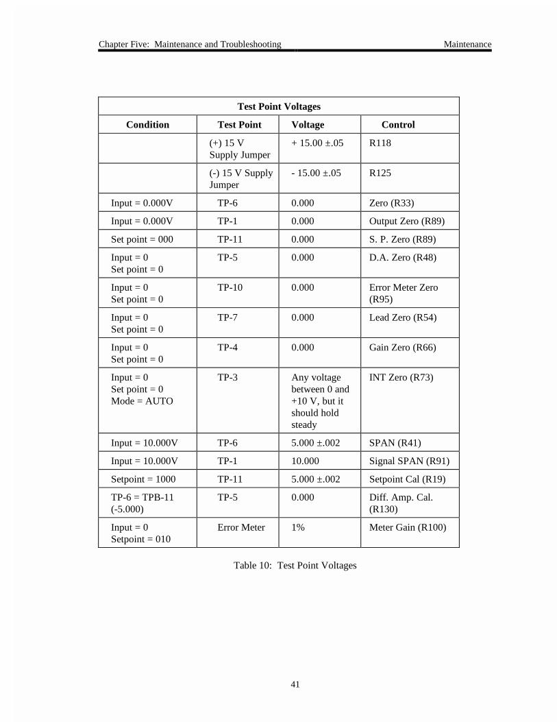
How To Perform the Controller Alignment Procedure
The following alignment procedure should be followed to verify the zero and full scale alignmentof the 250 controller. Allow the controller to warm up for at least 30 minutes. Note that themain P.C. board has a block of test pins TP-1, 2, 3, etc. located behind the connector for the rearpanel board.
Equipment Needed
• 0 to 10 volt source for input
• 100 ohm, 1 Watt resistor for load
• 4 and 1/2 place, 0 to 10 volt meter
Connections
1. Connect the input source to the INPUT connector Pins 1 and 8 (Pin 8 should also beconnected to Pin 12).
2. Connect the 100 ohm resistor to the VALVE connector Pins C and D.
3. Verify that the controls are in the following positions:
SETPOINT POT CCW (000)
SETPOINT INT/EXT INT
RANGE 10V
PHASE LEAD CCW
GAIN CW
MODE CLOSE
NORmal/REVerse NORMAL
115/230 (Rear Panel) As available
4. Verify that the A.C. supply is either 115 +15 or 230 +15 volts A.C.
5. Check the voltage at the test points listed in Table 10, page 41, and readjust theappropriate control if necessary.
Note Ref (GND) at the test DVM should be the A GND test point next to C18.
Chapter Five: Maintenance and Troubleshooting Maintenance
41
Test Point Voltages
Condition Test Point Voltage Control
(+) 15 VSupply Jumper
+ 15.00 ±.05 R118
(-) 15 V SupplyJumper
- 15.00 ±.05 R125
Input = 0.000V TP-6 0.000 Zero (R33)
Input = 0.000V TP-1 0.000 Output Zero (R89)
Set point = 000 TP-11 0.000 S. P. Zero (R89)
Input = 0Set point = 0
TP-5 0.000 D.A. Zero (R48)
Input = 0Set point = 0
TP-10 0.000 Error Meter Zero(R95)
Input = 0Set point = 0
TP-7 0.000 Lead Zero (R54)
Input = 0Set point = 0
TP-4 0.000 Gain Zero (R66)
Input = 0Set point = 0Mode = AUTO
TP-3 Any voltagebetween 0 and+10 V, but itshould holdsteady
INT Zero (R73)
Input = 10.000V TP-6 5.000 ±.002 SPAN (R41)
Input = 10.000V TP-1 10.000 Signal SPAN (R91)
Setpoint = 1000 TP-11 5.000 ±.002 Setpoint Cal (R19)
TP-6 = TPB-11(-5.000)
TP-5 0.000 Diff. Amp. Cal.(R130)
Input = 0Setpoint = 010
Error Meter 1% Meter Gain (R100)
Table 10: Test Point Voltages
Troubleshooting Chapter Five: Maintenance and Troubleshooting
42
Troubleshooting
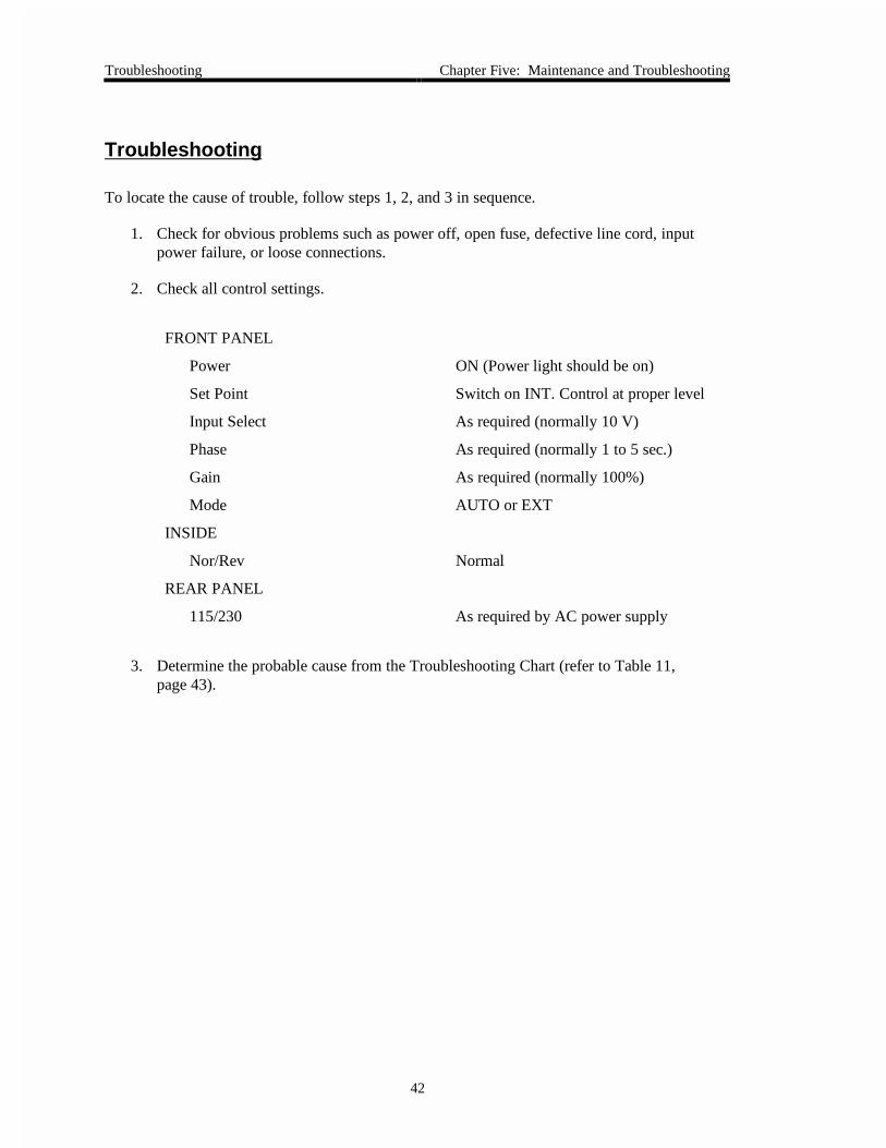
To locate the cause of trouble, follow steps 1, 2, and 3 in sequence.
1. Check for obvious problems such as power off, open fuse, defective line cord, inputpower failure, or loose connections.
2. Check all control settings.
FRONT PANEL
Power ON (Power light should be on)
Set Point Switch on INT. Control at proper level
Input Select As required (normally 10 V)
Phase As required (normally 1 to 5 sec.)
Gain As required (normally 100%)
Mode AUTO or EXT
INSIDE
Nor/Rev Normal
REAR PANEL
115/230 As required by AC power supply
3. Determine the probable cause from the Troubleshooting Chart (refer to Table 11,page 43).
Chapter Five: Maintenance and Troubleshooting Troubleshooting
43
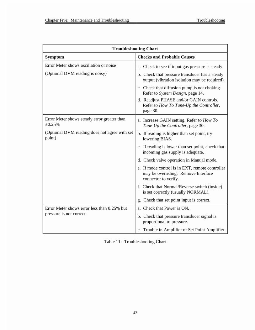
Troubleshooting Chart
Symptom Checks and Probable Causes
Error Meter shows oscillation or noise
(Optional DVM reading is noisy)
a. Check to see if input gas pressure is steady.
b. Check that pressure transducer has a steadyoutput (vibration isolation may be required).
c. Check that diffusion pump is not choking.Refer to System Design, page 14.
d. Readjust PHASE and/or GAIN controls.Refer to How To Tune-Up the Controller,page 30.
Error Meter shows steady error greater than±0.25%
(Optional DVM reading does not agree with setpoint)
a. Increase GAIN setting. Refer to How ToTune-Up the Controller, page 30.
b. If reading is higher than set point, trylowering BIAS.
c. If reading is lower than set point, check thatincoming gas supply is adequate.
d. Check valve operation in Manual mode.
e. If mode control is in EXT, remote controllermay be overriding. Remove Interfaceconnector to verify.
f. Check that Normal/Reverse switch (inside)is set correctly (usually NORMAL).
g. Check that set point input is correct.
Error Meter shows error less than 0.25% butpressure is not correct
a. Check that Power is ON.
b. Check that pressure transducer signal isproportional to pressure.
c. Trouble in Amplifier or Set Point Amplifier.
Table 11: Troubleshooting Chart

Troubleshooting Chapter Five: Maintenance and Troubleshooting
44
This page intentionally left blank.
Appendix A: Product Specifications
45
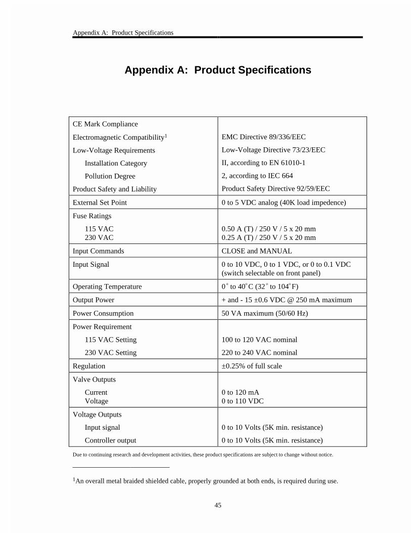
Appendix A: Product Specifications
CE Mark Compliance
Electromagnetic Compatibility1
Low-Voltage Requirements
Installation Category
Pollution Degree
Product Safety and Liability
EMC Directive 89/336/EEC
Low-Voltage Directive 73/23/EEC
II, according to EN 61010-1
2, according to IEC 664
Product Safety Directive 92/59/EEC
External Set Point 0 to 5 VDC analog (40K load impedence)
Fuse Ratings
115 VAC230 VAC
0.50 A (T) / 250 V / 5 x 20 mm0.25 A (T) / 250 V / 5 x 20 mm
Input Commands CLOSE and MANUAL
Input Signal 0 to 10 VDC, 0 to 1 VDC, or 0 to 0.1 VDC(switch selectable on front panel)
Operating Temperature 0 o to 40o C (32 o to 104o F)
Output Power + and - 15 ±0.6 VDC @ 250 mA maximum
Power Consumption 50 VA maximum (50/60 Hz)
Power Requirement
115 VAC Setting
230 VAC Setting
100 to 120 VAC nominal
220 to 240 VAC nominal
Regulation ±0.25% of full scale
Valve Outputs
CurrentVoltage
0 to 120 mA0 to 110 VDC
Voltage Outputs
Input signal
Controller output
0 to 10 Volts (5K min. resistance)
0 to 10 Volts (5K min. resistance)
Due to continuing research and development activities, these product specifications are subject to change without notice.
1An overall metal braided shielded cable, properly grounded at both ends, is required during use.

Appendix A: Product Specifications
46
This page intentionally left blank.
Appendix B: Model Code Explanation Model Code
47
Appendix B: Model Code Explanation
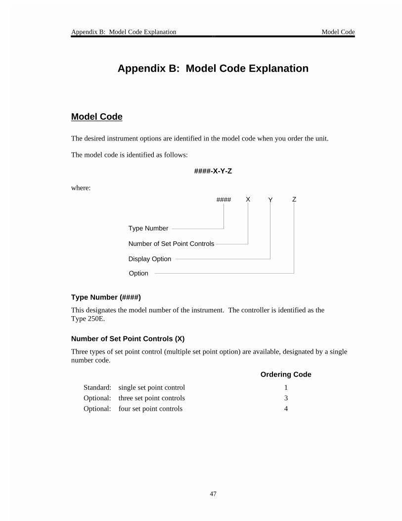
Model Code
The desired instrument options are identified in the model code when you order the unit.
The model code is identified as follows:
####-X-Y-Z
where:
Type Number
Display Option
Option
ZX Y####
Number of Set Point Controls
Type Number (####)
This designates the model number of the instrument. The controller is identified as theType 250E.
Number of Set Point Controls (X)
Three types of set point control (multiple set point option) are available, designated by a singlenumber code.
Ordering Code
Standard: single set point control 1
Optional: three set point controls 3
Optional: four set point controls 4
Model Code Appendix B: Model Code Explanation
48
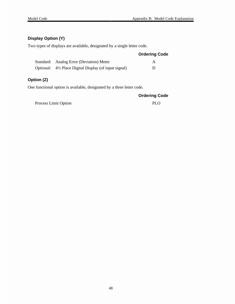
Display Option (Y)
Two types of displays are available, designated by a single letter code.
Ordering Code
Standard: Analog Error (Deviation) Meter A
Optional: 4½ Place Digital Display (of input signal) D
Option (Z)
One functional option is available, designated by a three letter code.
Ordering Code
Process Limit Option PLO
Index
49
Index
C
Cables, 10
Connectors
interface, 26
Customer support, 7
I
Installation Category, 13
L
Labels, 27
M
Manual organization, 7
Messages, definitions of, 4
Model code, 47
O
Operation
bias control, 31
dvm option, 33
external control, 32
initial setup, 29
manual control, 30
multiple set point option, 34
normal/reverse switch, 32
process limit option, 36
tune-up, 30
P
PCS, 23
Pollution Degree, 13
Pressure control signal, 23
R
Returning the product, 7, 9
S
Serial number label, 27
Setup
controller, 16
interconnections, 17
mass flow meter, 17
system design, 14
transducer, 17
valve, 16
Span adjustment, 24
T
Temperature, 13
Troubleshooting, 42