2509 2” DROP SPINDLE 2WD 4WD AWD >>> NOTE: Use P.N. 2508 ... · n) Re-attach the brake line...
7
2509-888 08/08 © A Division of KW AUTOMOTIVE North America, Inc. 1 INSTALLATION INSTRUCTIONS --1075 North Ave. Sanger, CA 93657-3539 local: 559-875-0222 fax: 559-876-2259 toll free: 800-445-3767-- 2509 2” DROP SPINDLE 2WD 4WD AWD >>> Must Use 17” Wheels or larger <<< 2007 CHEVY 1500 Pickup, Tahoe, Suburban, Avalanche >>> NOTE: Use P.N. 2508 for 2007 CHEVY 1500 “Classic” <<< Congratulations! You were selective enough to choose a BELLTECH PRODUCT. We have spent many hours developing our line of products so that you will receive maximum performance with minimum difficulty during installation. Note: Confirm that all of the hardware listed in the parts list is in the kit. Do not begin installation if any part is missing. Read the instructions thoroughly before beginning this installation. Warning: DO NOT work under a vehicle supported by only a jack. Place support stands securely under the vehicle in the manufacturer’s specified locations unless otherwise instructed. Warning: DO NOT drive vehicle until all work has been completed and checked. Torque all hardware to values specified. Reminder: Proper use of safety equipment and eye/face/hand protection is absolutely necessary when using these tools to perform procedures! Note: It is very helpful to have an assistant available during installation. RECOMMENDED TOOLS: • Properly rated floor jack, support stands, and wheel chocks • Combination wrench set • Hex Key (Allen) wrench set • Screwdriver set • Pliers • Chisel or punch and hammer • Abrasive cutter or grinder • Torque wrench: 0-200 lb ft. range • Ratcheting socket wrench and sockets sets • Safety Glasses KIT INSTALLATION 1. Open the hardware kit and remove all of the contents. Refer to the part list (Page 4) to verify that all parts are present. 2. Park the vehicle on a smooth, level concrete or seasoned asphalt surface and activate the parking brake. Block the REAR wheels of the vehicle with appropriate wheel chocks; making sure the vehicle’s transmission is in 1 st gear (manual) or “Park” (automatic). Using a properly rated floor jack, lift the front wheels of the vehicle off the ground. Place support stands, rated for the vehicle’s weight, in the factory specified locations. Refer to the vehicle Owner’s Manual. Prior to lowering the vehicle onto the stands, make sure the supports will securely contact the chassis.
Transcript of 2509 2” DROP SPINDLE 2WD 4WD AWD >>> NOTE: Use P.N. 2508 ... · n) Re-attach the brake line...

2509-888 08/08 © A Division of KW AUTOMOTIVE North America, Inc.
1
INSTALLATION INSTRUCTIONS
--1075 North Ave. Sanger, CA 93657-3539 local: 559-875-0222 fax: 559-876-2259 toll free: 800-445-3767--
2509 2” DROP SPINDLE 2WD 4WD AWD
>>> Must Use 17” Wheels or larger <<< 2007 CHEVY 1500 Pickup, Tahoe, Suburban, Avalanche
>>> NOTE: Use P.N. 2508 for 2007 CHEVY 1500 “Classic” <<<
Congratulations! You were selective enough to choose a BELLTECH PRODUCT. We have spent
many hours developing our line of products so that you will receive maximum performance with minimum difficulty during installation.
Note: Confirm that all of the hardware listed in the parts list is in the kit. Do not begin installation if
any part is missing. Read the instructions thoroughly before beginning this installation. Warning: DO NOT work under a vehicle supported by only a jack. Place support stands securely under
the vehicle in the manufacturer’s specified locations unless otherwise instructed. Warning: DO NOT drive vehicle until all work has been completed and checked. Torque all hardware to
values specified. Reminder: Proper use of safety equipment and eye/face/hand protection is absolutely necessary when
using these tools to perform procedures! Note: It is very helpful to have an assistant available during installation. RECOMMENDED TOOLS:
• Properly rated floor jack, support stands, and wheel chocks • Combination wrench set • Hex Key (Allen) wrench set • Screwdriver set • Pliers • Chisel or punch and hammer • Abrasive cutter or grinder • Torque wrench: 0-200 lb ft. range • Ratcheting socket wrench and sockets sets • Safety Glasses
KIT INSTALLATION
1. Open the hardware kit and remove all of the contents. Refer to the part list (Page 4) to verify that all parts are present.
2. Park the vehicle on a smooth, level concrete or seasoned asphalt surface and activate the parking brake. Block the REAR wheels of the vehicle with appropriate wheel chocks; making sure the vehicle’s transmission is in 1st gear (manual) or “Park” (automatic). Using a properly rated floor jack, lift the front wheels of the vehicle off the ground. Place support stands, rated for the vehicle’s weight, in the factory specified locations. Refer to the vehicle Owner’s Manual. Prior to lowering the vehicle onto the stands, make sure the supports will securely contact the chassis.
2509-888 08/08 © A Division of KW AUTOMOTIVE North America, Inc.
2
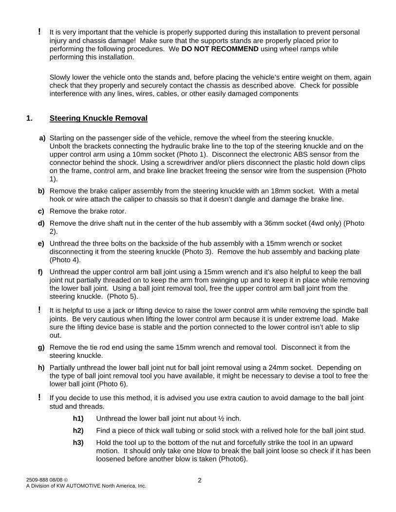
! It is very important that the vehicle is properly supported during this installation to prevent personal injury and chassis damage! Make sure that the supports stands are properly placed prior to performing the following procedures. We DO NOT RECOMMEND using wheel ramps while performing this installation.
Slowly lower the vehicle onto the stands and, before placing the vehicle’s entire weight on them, again check that they properly and securely contact the chassis as described above. Check for possible interference with any lines, wires, cables, or other easily damaged components
1. Steering Knuckle Removal
a) Starting on the passenger side of the vehicle, remove the wheel from the steering knuckle. Unbolt the brackets connecting the hydraulic brake line to the top of the steering knuckle and on the upper control arm using a 10mm socket (Photo 1). Disconnect the electronic ABS sensor from the connector behind the shock. Using a screwdriver and/or pliers disconnect the plastic hold down clips on the frame, control arm, and brake line bracket freeing the sensor wire from the suspension (Photo 1).
b) Remove the brake caliper assembly from the steering knuckle with an 18mm socket. With a metal hook or wire attach the caliper to chassis so that it doesn’t dangle and damage the brake line.
c) Remove the brake rotor.
d) Remove the drive shaft nut in the center of the hub assembly with a 36mm socket (4wd only) (Photo 2).
e) Unthread the three bolts on the backside of the hub assembly with a 15mm wrench or socket disconnecting it from the steering knuckle (Photo 3). Remove the hub assembly and backing plate (Photo 4).
f) Unthread the upper control arm ball joint using a 15mm wrench and it’s also helpful to keep the ball joint nut partially threaded on to keep the arm from swinging up and to keep it in place while removing the lower ball joint. Using a ball joint removal tool, free the upper control arm ball joint from the steering knuckle. (Photo 5).
! It is helpful to use a jack or lifting device to raise the lower control arm while removing the spindle ball joints. Be very cautious when lifting the lower control arm because it is under extreme load. Make sure the lifting device base is stable and the portion connected to the lower control isn’t able to slip out.
g) Remove the tie rod end using the same 15mm wrench and removal tool. Disconnect it from the steering knuckle.
h) Partially unthread the lower ball joint nut for ball joint removal using a 24mm socket. Depending on the type of ball joint removal tool you have available, it might be necessary to devise a tool to free the lower ball joint (Photo 6).
! If you decide to use this method, it is advised you use extra caution to avoid damage to the ball joint stud and threads.
h1) Unthread the lower ball joint nut about ½ inch.
h2) Find a piece of thick wall tubing or solid stock with a relived hole for the ball joint stud.
h3) Hold the tool up to the bottom of the nut and forcefully strike the tool in an upward motion. It should only take one blow to break the ball joint loose so check if it has been loosened before another blow is taken (Photo6).

2509-888 08/08 © A Division of KW AUTOMOTIVE North America, Inc.
3
! Another known way to remove the lower ball joint is to use a large hammer and forcefully strike the lower ball joint boss. This striking action will usually free the ball joint with one swing.
i) Remove the steering knuckle from the vehicle (Photo 7).
2. Steering Knuckle Installation
a) Trim 3/8” to 1/2” off the lower portion on the upper control arm ball joint for clearance to the 4wd drive shaft grease boot (Photo 8 & 12). Not needed if your vehicle is 2WD.
b) Locate the new Belltech passenger side steering knuckle.
c) Insert the upper hub bolt in from the back of the new Belltech steering knuckle. This needs to be done before the upper ball joint is attached.
d) Attach the new steering knuckle to the upper and lower ball joints and loosely thread the nuts in place. Make sure to place the drive shaft end inside the hub opening.
! It is helpful to use a jack or lifting device to raise the lower control arm while re-attaching the spindle ball joints. Be very cautious while lifting the lower control arm because it is under extreme load. Make sure the lifting device base is stable and the portion connected to the lower control isn’t able to slip out.
e) Before attaching the hub assembly, secure the upper ball joint nut in place and torque to 20 ft-lbs.
f) With an impact gun, secure the lower ball joint and tie rod end in place (Photo 9). Once secure, torque the lower ball joint to 75 ft-lbs.
g) Secure the steering tie rod end and torque to 20 ft-lbs.
h) Install the backing plate and hub assembly back onto the splined drive shaft.
i) Insert the three stock hub bolts in from the backside of the steering knuckle and torque to 110 ft-lbs (Photo 10).
j) Install and torque the drive shaft center hub bolt to 175 ft-lbs (4wd only) (Photo 11).
k) It is very important to rotate the hub to check that the upper ball joint stud or nut does not come in contact with the drive shaft boot (4wd only) (Photo 12).
l) Install the brake rotor.
m) Install the brake caliper assembly and torque bolts to 90 ft-lbs (Photo 13).
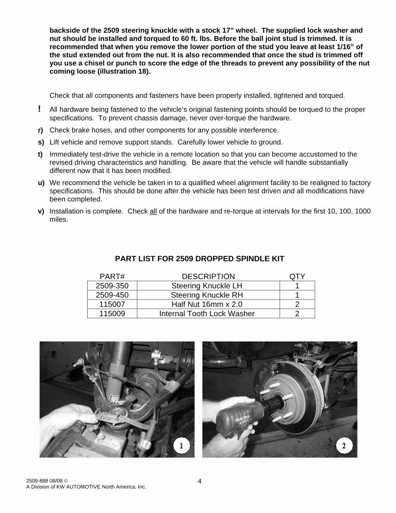
n) Re-attach the brake line brackets to the top of the steering knuckle and to the control arm (Photo 14 &15).
o) Re-attach the ABS sensor connector and the hold down clips (Photo 14 &15).
p) Rotate the steering knuckle in both directions to check if the brake line and ABS cable have enough slack (Photo 15). If one or the other seams to be to tight, then you should pull it thru the bracket to give it the proper amount of slack.
q) Passenger side installation is complete (Photo 16) fallow steps 1-27for driver’s side.
Final assembly and adjustments
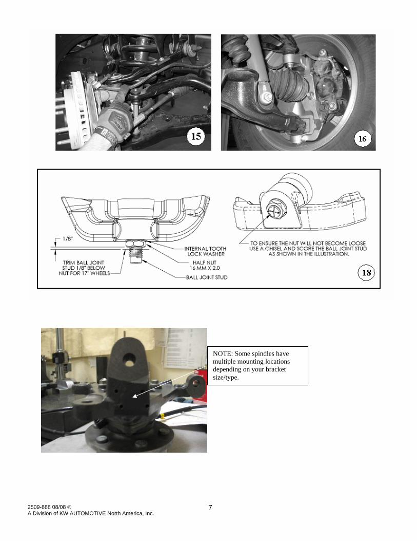
! When using 17” wheels you must use the supplied nut and lock washer on the lower ball joint then trim the ball joint stud for adequate clearance (illustration 18). Photo 16 shows the
2509-888 08/08 © A Division of KW AUTOMOTIVE North America, Inc.
4
backside of the 2509 steering knuckle with a stock 17” wheel. The supplied lock washer and nut should be installed and torqued to 60 ft. lbs. Before the ball joint stud is trimmed. It is recommended that when you remove the lower portion of the stud you leave at least 1/16” of the stud extended out from the nut. It is also recommended that once the stud is trimmed off you use a chisel or punch to score the edge of the threads to prevent any possibility of the nut coming loose (illustration 18).
Check that all components and fasteners have been properly installed, tightened and torqued.
! All hardware being fastened to the vehicle’s original fastening points should be torqued to the proper specifications. To prevent chassis damage, never over-torque the hardware.
r) Check brake hoses, and other components for any possible interference.
s) Lift vehicle and remove support stands. Carefully lower vehicle to ground.
t) Immediately test-drive the vehicle in a remote location so that you can become accustomed to the revised driving characteristics and handling. Be aware that the vehicle will handle substantially different now that it has been modified.
u) We recommend the vehicle be taken in to a qualified wheel alignment facility to be realigned to factory specifications. This should be done after the vehicle has been test driven and all modifications have been completed.
v) Installation is complete. Check all of the hardware and re-torque at intervals for the first 10, 100, 1000 miles.
PART LIST FOR 2509 DROPPED SPINDLE KIT
PART# DESCRIPTION QTY 2509-350 Steering Knuckle LH 1 2509-450 Steering Knuckle RH 1 115007 Half Nut 16mm x 2.0 2 115009 Internal Tooth Lock Washer 2

2509-888 08/08 © A Division of KW AUTOMOTIVE North America, Inc.
5

2509-888 08/08 © A Division of KW AUTOMOTIVE North America, Inc.
6
2509-888 08/08 © A Division of KW AUTOMOTIVE North America, Inc.
7
NOTE: Some spindles have multiple mounting locations depending on your bracket size/type.