250-1859 Rostra.com Cruise Control
12
HONDA / HYUNDAI / KIA ELECTRONIC CRUISE KIT Part Number: 250-1859 AUTOMATIC AND MANUAL TRANSMISSION Form #5231, Rev. C, 08-00-10 General Applicability Kit Contents/Service Parts Contents of Hardware Bag Qty Description 8 Wire Zip Ties Safety Tools Gloves, Safety Glasses Special Tools Volt-Ohm Meter Installation Tools Side cutter To cut wire ties Drill Bit or Knockout Punch 9.5mm or 3/8” (for switch) 10mm wrench Soldering Tool Special Chemicals 2010 Honda Insight 07-10 Kia Optima / Forte / Rondo 10-11 Hyundai Tucson / Elantra Touring ETC Item # Qty. Description 1. 250-2763 1 Cruise Control Module 2. 250-2760 1 Switch Harness 3. 250-2759 1 Main Wiring Harness 4. 250-2771 1 Pedal Interface Harness 5. 1 Hardware Kit 6. 250-3742 1 Control Switch Note: Item # Accessory 1 2 3 Legend Conflicts STOP STOP: Damage to the vehicle may occur. Do not proceed until process has been complied with. OPERATOR SAFETY: Use caution to avoid risk of injury CRITICAL PROCESS: Proceed with caution to ensure a quality installation. GENERAL PROCESS: This highlights specific processes to ensure a quality installation. TOOLS & EQUIPMENT: This calls out the specific tools and equipment required for this process Recommended Sequence of Application Recommended Tools 1 3 2 4 5 6 DUE TO SENSITIVE NATURE OF SIGNALS USED FOR THIS PRODUCT ALL NON PLUG AND PLAY CONNECTIONS MUST BE SOLDERED. FAILURE TO COMPLY WITH THIS REQUIREMENT WILL VOID WARRANTY. THIS DEVICE IS NOT INTENDED FOR USE IN VEHICLES WITH 2-WAY RADIOS.
description
Cruise Control Rostra
Transcript of 250-1859 Rostra.com Cruise Control

HONDA / HYUNDAI / KIA ELECTRONIC CRUISE KIT Part Number: 250-1859 AUTOMATIC AND MANUAL TRANSMISSION
Form #5231, Rev. C, 08-00-10
General Applicability
Kit Contents/Service Parts Contents of Hardware Bag Qty Description
8 Wire Zip Ties
Safety Tools Gloves, Safety Glasses Special Tools Volt-Ohm Meter Installation Tools Side cutter To cut wire ties Drill Bit or Knockout Punch 9.5mm or 3/8” (for switch) 10mm wrench Soldering Tool Special Chemicals
2010 Honda Insight 07-10 Kia Optima / Forte / Rondo 10-11 Hyundai Tucson / Elantra Touring ETC
Item # Qty. Description 1. 250-2763 1 Cruise Control Module 2. 250-2760 1 Switch Harness 3. 250-2759 1 Main Wiring Harness 4. 250-2771 1 Pedal Interface Harness 5. 1 Hardware Kit 6. 250-3742 1 Control Switch
Note:
Item # Accessory 1 2 3
Legend
Conflicts
STOP STOP: Damage to the vehicle may occur. Do not proceed until process has been complied with. OPERATOR SAFETY: Use caution to avoid risk of injury CRITICAL PROCESS: Proceed with caution to ensure a quality installation. GENERAL PROCESS: This highlights specific processes to ensure a quality installation. TOOLS & EQUIPMENT: This calls out the specific tools and equipment required for this process
Recommended Sequence of Application
Recommended Tools
1
3 2 4
5
6
DUE TO SENSITIVE NATURE OF SIGNALS USED FOR THIS PRODUCT ALL NON PLUG AND PLAY CONNECTIONS MUST BE SOLDERED. FAILURE TO COMPLY WITH THIS REQUIREMENT WILL VOID WARRANTY. THIS DEVICE IS NOT INTENDED FOR USE IN VEHICLES WITH 2-WAY RADIOS.
HONDA / HYUNDAI / KIA ELECTRONIC CRUISE KIT Part Number: 250-1859 AUTOMATIC AND MANUAL TRANSMISSION
Page 2
Section I – Installation Procedure
A. Pre-Installation Suggestions
1. It is advisable to disconnect the negative battery cable for 3 minutes before beginning installation, to avoid unintended air bag deployment. Note and record any anti-theft radio codes prior to disconnecting. Figure 1
2. Remove the driver side lower dash and kick panels. Remove the steering wheel shroud.
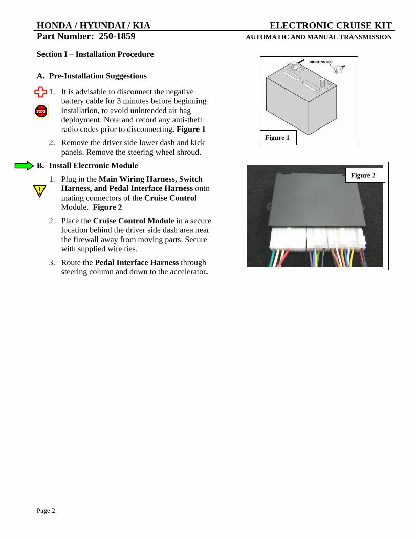
B. Install Electronic Module 1. Plug in the Main Wiring Harness, Switch
Harness, and Pedal Interface Harness onto mating connectors of the Cruise Control Module. Figure 2
2. Place the Cruise Control Module in a secure location behind the driver side dash area near the firewall away from moving parts. Secure with supplied wire ties.
3. Route the Pedal Interface Harness through steering column and down to the accelerator.
Figure 1
Insight Figure 2
HONDA / HYUNDAI / KIA ELECTRONIC CRUISE KIT Part Number: 250-1859 AUTOMATIC AND MANUAL TRANSMISSION
Page 3
C. Install Pedal Interface Harness 1. Use the diagram and chart below to install the
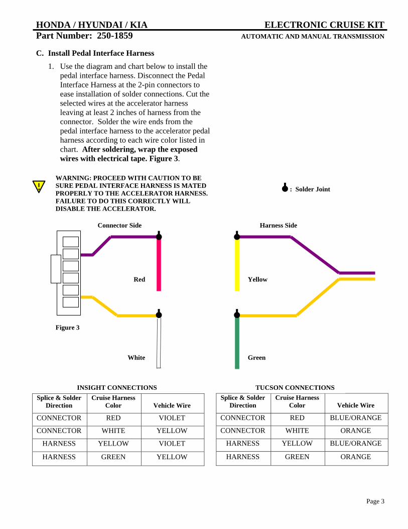
pedal interface harness. Disconnect the Pedal Interface Harness at the 2-pin connectors to ease installation of solder connections. Cut the selected wires at the accelerator harness leaving at least 2 inches of harness from the connector. Solder the wire ends from the pedal interface harness to the accelerator pedal harness according to each wire color listed in chart. After soldering, wrap the exposed wires with electrical tape. Figure 3.
Splice & Solder Direction
Cruise Harness Color Vehicle Wire
CONNECTOR RED VIOLET
CONNECTOR WHITE YELLOW
HARNESS YELLOW VIOLET
HARNESS GREEN YELLOW
Splice & Solder Direction
Cruise Harness Color Vehicle Wire
CONNECTOR RED BLUE/ORANGE
CONNECTOR WHITE ORANGE
HARNESS YELLOW BLUE/ORANGE
HARNESS GREEN ORANGE
TUCSON CONNECTIONS INSIGHT CONNECTIONS
WARNING: PROCEED WITH CAUTION TO BE SURE PEDAL INTERFACE HARNESS IS MATED PROPERLY TO THE ACCELERATOR HARNESS. FAILURE TO DO THIS CORRECTLY WILL DISABLE THE ACCELERATOR.
Connector Side Harness Side
Red Yellow
White Green
Figure 3
: Solder Joint
HONDA / HYUNDAI / KIA ELECTRONIC CRUISE KIT Part Number: 250-1859 AUTOMATIC AND MANUAL TRANSMISSION
Page 4
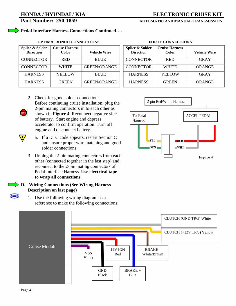
Pedal Interface Harness Connections Continued….
2. Check for good solder connection:
Before continuing cruise installation, plug the 2-pin mating connectors in to each other as shown in Figure 4. Reconnect negative side of battery. Start engine and depress accelerator to confirm operation. Turn off engine and disconnect battery.
a. If a DTC code appears, restart Section C and ensure proper wire matching and good solder connections.
3. Unplug the 2-pin mating connectors from each other (connected together in the last step) and reconnect to the 2-pin mating connectors of Pedal Interface Harness. Use electrical tape to wrap all connections.
D. Wiring Connections (See Wiring Harness Description on last page)
1. Use the following wiring diagram as a reference to make the following connections:
Splice & Solder Direction
Cruise Harness Color Vehicle Wire
CONNECTOR RED GRAY
CONNECTOR WHITE ORANGE
HARNESS YELLOW GRAY
HARNESS GREEN ORANGE
Splice & Solder Direction
Cruise Harness Color Vehicle Wire
CONNECTOR RED BLUE
CONNECTOR WHITE GREEN/ORANGE
HARNESS YELLOW BLUE
HARNESS GREEN GREEN/ORANGE
OPTIMA, RONDO CONNECTIONS
2-pin Red/White Harness
RED
WHT GRN
YEL
To Pedal Harness
ACCEL PEDAL
Figure 4
GND Black
12V IGN Red
BRAKE + Blue
BRAKE - White/Brown
CLUTCH (GND TRG) White
CLUTCH (+12V TRG) Yellow
Cruise Module VSS
Violet
FORTE CONNECTIONS

HONDA / HYUNDAI / KIA ELECTRONIC CRUISE KIT Part Number: 250-1859 AUTOMATIC AND MANUAL TRANSMISSION
Page 5
E. Insight Wiring Connections (It is advisable use solder for all wiring connections) 1. Locate the following wires to connect to the
main harness from the control module:
2. Connect the Main Harness to vehicle wire by using the chart below.
Function Cruise Harness
Color Vehicle Wire
IGN RED RED
BRAKE + BLUE VIOLET
BRAKE - WHITE/BROWN WHITE
VSS VIOLET BLUE
CLUTCH SWITCH WHITE PAGE 4
3. Apply the Black Ground Wire from the Main Harness to the Vehicle Ground Point at the kick panel. Figure 7
4. VSS: Locate the fuse/relay box under the driver side dash. Look for bottom white connector between yellow and blue connector. Connect the Violet Wire from the Main Wiring Harness to the Blue Wire of the connector. Figure 8
Function See Fig. Vehicle Color
IGN 5 RED
BRAKE + 6 VIOLET
BRAKE - 6 WHITE
GROUND 7 GROUND POINT
VSS 8 BLUE
CLUTCH SWITCH PAGE 4
Driver Kick Panel Figure 7
GND
VSS
Figure 8
Brake Switch
Pin 1 White
Pin 2 Violet
Figure 6
Junction Box
IGNITION
Figure 5
HONDA / HYUNDAI / KIA ELECTRONIC CRUISE KIT Part Number: 250-1859 AUTOMATIC AND MANUAL TRANSMISSION
Page 6
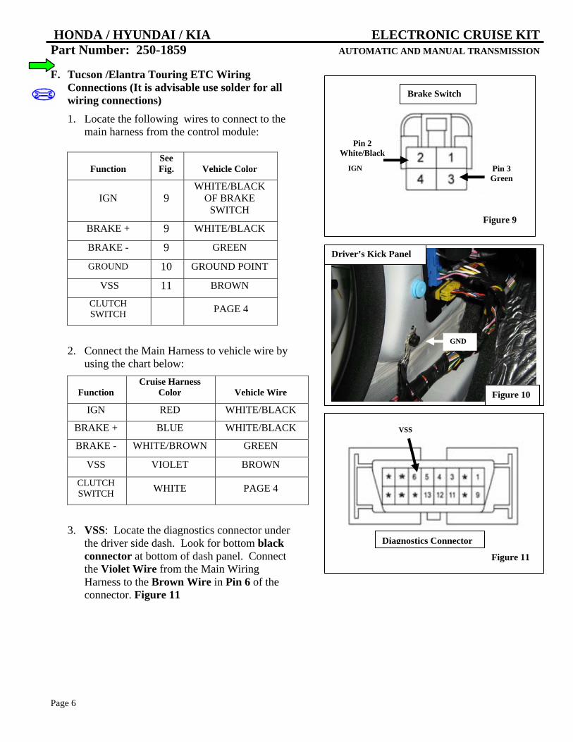
F. Tucson /Elantra Touring ETC Wiring Connections (It is advisable use solder for all wiring connections) 1. Locate the following wires to connect to the
main harness from the control module:
2. Connect the Main Harness to vehicle wire by using the chart below:
Function Cruise Harness
Color Vehicle Wire
IGN RED WHITE/BLACK
BRAKE + BLUE WHITE/BLACK
BRAKE - WHITE/BROWN GREEN
VSS VIOLET BROWN
CLUTCH SWITCH WHITE PAGE 4
3. VSS: Locate the diagnostics connector under the driver side dash. Look for bottom black connector at bottom of dash panel. Connect the Violet Wire from the Main Wiring Harness to the Brown Wire in Pin 6 of the connector. Figure 11
Function See Fig. Vehicle Color
IGN 9 WHITE/BLACK
OF BRAKE SWITCH
BRAKE + 9 WHITE/BLACK
BRAKE - 9 GREEN
GROUND 10 GROUND POINT
VSS 11 BROWN
CLUTCH SWITCH PAGE 4
Figure 10
Driver’s Kick Panel
GND
Brake Switch
Pin 2 White/Black
Pin 3 Green
IGN
Figure 9
Diagnostics Connector
Figure 11
VSS
HONDA / HYUNDAI / KIA ELECTRONIC CRUISE KIT Part Number: 250-1859 AUTOMATIC AND MANUAL TRANSMISSION
Page 7
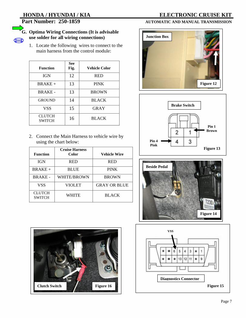
G. Optima Wiring Connections (It is advisable use solder for all wiring connections) 1. Locate the following wires to connect to the
main harness from the control module:
2. Connect the Main Harness to vehicle wire by using the chart below:
Function See Fig. Vehicle Color
IGN 12 RED
BRAKE + 13 PINK
BRAKE - 13 BROWN
GROUND 14 BLACK
VSS 15 GRAY
CLUTCH SWITCH 16 BLACK
Function Cruise Harness
Color Vehicle Wire
IGN RED RED
BRAKE + BLUE PINK
BRAKE - WHITE/BROWN BROWN
VSS VIOLET GRAY OR BLUE
CLUTCH SWITCH WHITE BLACK
Beside Pedal
Figure 14
Junction Box
Figure 12
Brake Switch
Pin 4 Pink
Pin 1 Brown
Figure 13
Diagnostics Connector
Figure 15
VSS
Figure 16 Clutch Switch

HONDA / HYUNDAI / KIA ELECTRONIC CRUISE KIT Part Number: 250-1859 AUTOMATIC AND MANUAL TRANSMISSION
Page 8
H. Install Control Switch 1. Use the lever wedges on the Control Switch
at an angle template to drill a 3/8” or 9.5mm hole in the lower shroud of the steering column cover. Position lock-washers as shown. Figure 17
2. Apply nut and position Control Switch for driver’s best view.
3. Assemble (2) 3-pin connectors from the sack parts to the mating wire colors on the Control Switch Harness. Use the diagram to mate the module harness to switch harness. Figure 18
4. Route the assembled Control Switch Harness to the mating connector of the Cruise Control module.
5. Secure the Control Switch Harness with zip ties away from moving parts.
I. Testing 1. Reconnect negative battery cable and torque
to 35 in*lbs. Reenter anti-theft radio codes.
2. Turn ignition on. Apply the on/off button of Cruise Control Switch.
J. Reassembly 1. Reinstall all removed pieces taking care to
ensure harnesses and wiring connections are properly secured.
2. Make sure all harnesses are not pinched or bound by trim pieces.
From Module From Switch
Figure 18
Figure 17
Figure 19 Tucson
HONDA / HYUNDAI / KIA ELECTRONIC CRUISE KIT Part Number: 250-1859 AUTOMATIC AND MANUAL TRANSMISSION
Page 9
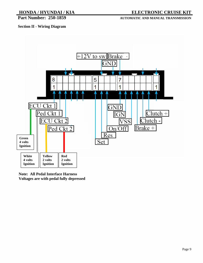
Section II - Wiring Diagram
Green 4 volts Ignition
White 4 volts Ignition
Yellow 2 volts Ignition
Red 2 volts Ignition
-
Note: All Pedal Interface Harness Voltages are with pedal fully depressed
HONDA / HYUNDAI / KIA ELECTRONIC CRUISE KIT Part Number: 250-1859 AUTOMATIC AND MANUAL TRANSMISSION
Page 10
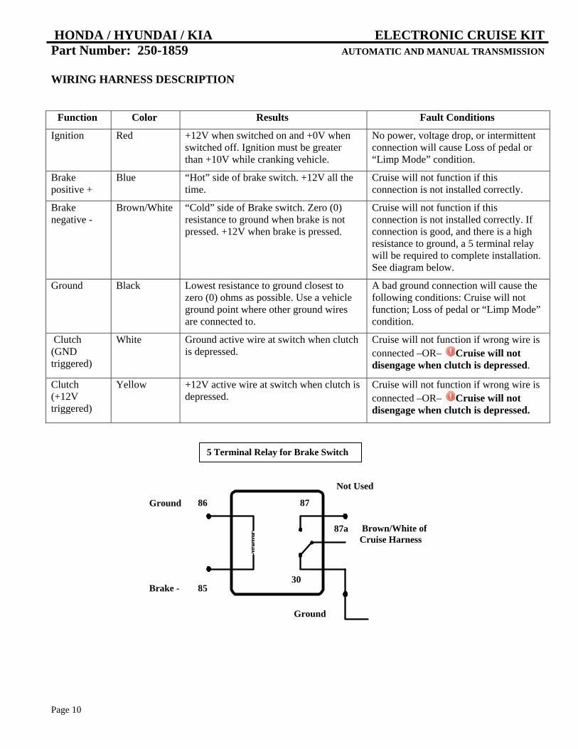
WIRING HARNESS DESCRIPTION
Function Color Results Fault Conditions
Ignition Red +12V when switched on and +0V when switched off. Ignition must be greater than +10V while cranking vehicle.
No power, voltage drop, or intermittent connection will cause Loss of pedal or “Limp Mode” condition.
Brake positive +
Blue “Hot” side of brake switch. +12V all the time.
Cruise will not function if this connection is not installed correctly.
Brake negative -
Brown/White “Cold” side of Brake switch. Zero (0) resistance to ground when brake is not pressed. +12V when brake is pressed.
Cruise will not function if this connection is not installed correctly. If connection is good, and there is a high resistance to ground, a 5 terminal relay will be required to complete installation. See diagram below.
Ground Black Lowest resistance to ground closest to zero (0) ohms as possible. Use a vehicle ground point where other ground wires are connected to.
A bad ground connection will cause the following conditions: Cruise will not function; Loss of pedal or “Limp Mode” condition.
Clutch (GND triggered)
White Ground active wire at switch when clutch is depressed.
Cruise will not function if wrong wire is connected –OR– Cruise will not disengage when clutch is depressed.
Clutch (+12V triggered)
Yellow +12V active wire at switch when clutch is depressed.
Cruise will not function if wrong wire is connected –OR– Cruise will not disengage when clutch is depressed.
5 Terminal Relay for Brake Switch
86
85
87
87a
30
Ground
Brake -
Not Used
Brown/White of Cruise Harness
Ground

HONDA / HYUNDAI / KIA ELECTRONIC CRUISE KIT Part Number: 250-1859 AUTOMATIC AND MANUAL TRANSMISSION
Page 11