25. Electrical System - Europa Aircraft - 25 - ELECTRICAL SYSTEM.… · 25. Electrical System...
12
25. Electrical System Introduction Whilst in general electrical items are not included in the Europa kit - mainly because virtually every builder will want a customised instrument panel, this is a good stage at which the electrical installation could be carried out. We have included an Annex (Annex D) at the back of the manual, which gives a good introduction to the theory and general principles of electrical design and installation. What follows in this chapter is a set of recommendations specific to the Europa, but which is sufficiently general to apply to most installations. Planning It is important to plan the electrical system at an early stage. While there are many possible solutions which will work, you should aim for a safe, reliable system which will operate in a logical and straightforward manner. Ensure that your inspector is kept informed of your plan for the system and has the opportunity to advise you on anything you may be unsure of before it becomes difficult or impossible to change. You are strongly recommended to work to a detailed circuit diagram and layout plan, having gathered components in each area together to ensure they will all fit before cutting or drilling mounting points. You will know every cable and connector by the time you have finished the system, but a month later the details will have faded from memory. Weight considerations Although there is often a great temptation to give your Europa cockpit a mini ‘biz-jet’ look by packing the panel with all kinds of gadgets, ask yourself first “will I really need this?” The addition of a second radio, for example, although offering redundancy if the first one fails, will most likely be dead weight that will be carried on every flight you make. Consider also that with each piece of extra equipment there will almost always be more wiring, connectors, another circuit breaker or switch, all adding to the already added weight. Switches The rule for operation of switches in aircraft is UP/FORWARD for ON, DOWN/BACK for OFF. Contact numbers marked on the switches to identify terminals may be shown, and the contact positions markers “normally closed” (NC) or “normally open” (NO). Europa Build Manual December 2009 Page 1 - 1
Transcript of 25. Electrical System - Europa Aircraft - 25 - ELECTRICAL SYSTEM.… · 25. Electrical System...
25. Electrical System
Introduction
Whilst in general electrical items are not included in the Europa kit - mainly because virtually everybuilder will want a customised instrument panel, this is a good stage at which the electricalinstallation could be carried out.
We have included an Annex (Annex D) at the back of the manual, which gives a good introduction tothe theory and general principles of electrical design and installation.
What follows in this chapter is a set of recommendations specific to the Europa, but which issufficiently general to apply to most installations.
Planning
It is important to plan the electrical system at an early stage. While there are many possible solutionswhich will work, you should aim for a safe, reliable system which will operate in a logical andstraightforward manner. Ensure that your inspector is kept informed of your plan for the system andhas the opportunity to advise you on anything you may be unsure of before it becomes difficult orimpossible to change. You are strongly recommended to work to a detailed circuit diagram andlayout plan, having gathered components in each area together to ensure they will all fit beforecutting or drilling mounting points. You will know every cable and connector by the time you havefinished the system, but a month later the details will have faded from memory.
Weight considerations
Although there is often a great temptation to give your Europa cockpit a mini ‘biz-jet’ look bypacking the panel with all kinds of gadgets, ask yourself first “will I really need this?”
The addition of a second radio, for example, although offering redundancy if the first one fails, willmost likely be dead weight that will be carried on every flight you make. Consider also that with eachpiece of extra equipment there will almost always be more wiring, connectors, another circuitbreaker or switch, all adding to the already added weight.
Switches
The rule for operation of switches in aircraft is UP/FORWARD for ON, DOWN/BACK for OFF.
Contact numbers marked on the switches to identify terminals may be shown, and the contactpositions markers “normally closed” (NC) or “normally open” (NO).
Europa Build Manual December 2009 Page 1 - 1
Circuit breakers
An important characteristic of a circuit breaker is that it can be reset, usually by pushing a button in orpressing a rocker switch. Some designs allow the breaker to be held in contact even if the overloadpersists : this is a good way to discover which way the smoke circulates in your cockpit, but is notrecommended. The preferred type for aircraft is “trip-free”, which means it cannot be reset while theoverload persists. Whatever type is fitted, the rule is that you should never make more than oneattempt to reset a breaker in the air - and then only if that circuit is needed. Remember that resettingwill not cure the fault that caused the breaker to trip.
Some circuit breakers are designed as switches. This saves having a separate switch to control thecircuit. Do not use other types of circuit breaker as switches, as their reliability may suffer, althoughthey may be tripped for maintenance purposes on an occasional basis.
Wiring standards
Wiring and connections should be of aircraft quality. Because homebuilt aircraft are not to certifiedstandards, you do not need to pay for every item to come from a certified source ; we stronglyrecommend that you satisfy yourself as to the quality of all material being suitable for aircraft use.
In particular, you should avoid wiring with poly-vinyl chloride (PVC) insulation, as this isflammable and gives off toxic fumes when overheated or burnt. Insulation coatings such asethylethene/tetrafluoroethylene (ETFE, trade name TEFZEL, to specification MIL-W-22759/16) orpolyvinylidene fluoride (PVF, as in Raychem Type 44) have good insulation and abrasion resistanceand low toxicity of fumes, with temperature ratings to 150°C (heat-shrink sleeving can be addedwhere necessary without risk of damaging the wiring in the process).
Stranded wire cables should always be used in aircraft. Single conductors are less flexible and moreprone to fatigue fracture under conditions of aircraft vibration -especially if the wire has been nickedin the course of stripping its insulation while preparing to terminate it. Multi-strand cables are morereliable, although care should be taken to see that all strands have entered the crimp ferrule or solderbucket: stray strands are a sure way of getting short-circuits and testing the circuit protection! Allwiring should use appropriate terminations - it is not acceptable practice in aircraft to clamp barewires into screwed terminals. Each wire should be secured by crimping or soldering to a terminal orcontact which is then clamped with a screw or held in a connector.
Cables should be restrained from movement, especially near the termination so that there is nomovement between the wire and its terminal - plugs with cable clamps are very good; where anumber of wires emerge from a terminal block or row of switches they should immediately be tiedtogether with lacing thread or tie wraps to form a loom, then the loom should be clamped to thestructure at frequent intervals so that it does not have a chance to move about, always ensuring thateach wire is long enough to avoid pulling on its termination or being kinked into a sharp bend. A ruleof thumb is that no individual wire should be bent into a curve sharper than a radius of 6 times itsdiameter (including insulation), and no loom should have a bend radius less than 10 times that of thelargest diameter cable in it.
Page 1 - 2 December 2009 Europa Build Manual
Identify each cable at both ends so that you can match it with your diagram and trace it if required at alater date.
Wiring - current rating
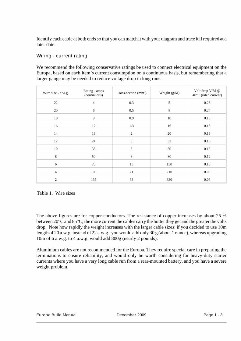
We recommend the following conservative ratings be used to connect electrical equipment on theEuropa, based on each item’s current consumption on a continuous basis, but remembering that alarger gauge may be needed to reduce voltage drop in long runs.
Wire size - a.w.g. Rating - amps(continuous) Cross-section (mm2) Weight (g/M) Volt drop V/M @
40°C (rated current)
22 4 0.3 5 0.26
20 6 0.5 8 0.24
18 9 0.9 10 0.18
16 12 1.3 16 0.18
14 18 2 20 0.18
12 24 3 32 0.16
10 35 5 50 0.13
8 50 8 80 0.12
6 70 13 130 0.10
4 100 21 210 0.09
2 135 33 330 0.08
The above figures are for copper conductors. The resistance of copper increases by about 25 %between 20°C and 85°C; the more current the cables carry the hotter they get and the greater the voltsdrop. Note how rapidly the weight increases with the larger cable sizes: if you decided to use 10mlength of 20 a.w.g. instead of 22 a.w.g., you would add only 30 g (about 1 ounce), whereas upgrading10m of 6 a.w.g. to 4 a.w.g. would add 800g (nearly 2 pounds).
Aluminium cables are not recommended for the Europa. They require special care in preparing theterminations to ensure reliability, and would only be worth considering for heavy-duty startercurrents where you have a very long cable run from a rear-mounted battery, and you have a severeweight problem.
Europa Build Manual December 2009 Page 1 - 3
Table 1. Wire sizes
Because aluminium is not as good a conductor as copper, a larger cable cross-section is needed (e.g.2 a.w.g. instead of 4 a.w.g.) for the same current. If you must use aluminium cables, get specialistadvice on termination, installation and husbandry.
Connectors
Connectors come in a very wide range of types and sizes. They serve 2 prime purposes: to connectaircraft wiring to an item of installed equipment, where you have no choice but to use the plug orsocket designed to mate with whatever socket or plug is fitted to the item; and to provide anaccessible means of disconnecting a cable or group of cables at a convenient point without having toundo the screwed terminations - this is especially useful for the instrument panel, so that it can befitted out while removed from the aircraft, then installed and quickly connected to the rest of theaircraft wiring. It can equally easily be removed for maintenance.
Aircraft standard connectors are designed to be light in weight, with a screwed or bayonet ring, withenvironmental seals to avoid moisture ingress, and cable clamps to ensure that stress on the wiringloom does not cause strain between the cables and the contacts they are connected to. Contactsmaybe crimped onto the cables and subsequently inserted into the connector, or cables may besoldered onto fixed contacts. Catalogues show a bewildering variety of options, but once you havedecided where you want to use them, the number and sizes of cables to be connected, you should beable to select the correct plugs and sockets. Normally a “bulkhead” or “chassis” socket or plug willonly mate with a matching “free” or “cable” plug or socket - so one half should always be mounted(using a flange or a jam nut) - you should not attempt to have a free plug and free socket connecting 2parts of a loom.
For safely reasons, the “live” side of each connection should be a socket contact so that aninadvertent short circuit is less likely (e.g. while disconnected for testing).
If you have a circuit where integrity of connection is vital (e.g. pitch trim) it is possible to connect 2pins in parallel to ensure a single failure does not cause a problem. However it is not considered goodpractice to use this method to share the current where the contacts are too low a rating to carry theload through one pin - use a connector with adequately-sized contacts.
Aircraft standard connectors are expensive, but are not essential for a homebuilt aircraft, and othertypes of multi-way connector can be used. Make sure they are of good quality, with some positivemeans of locking to prevent disconnection under vibration.
Battery
Batteries are available in a variety of sizes and types. The main battery should be capable of crankingthe engine under all conditions you are likely to operate the Europa, especially at low temperatureswhen battery output is low, and the torque needed to crank the engine is high because oil viscosity ishigh. Rotax recommend a minimum of 16 AH to operate their 912 engine. If you wish to fit a largecapacity battery, remember that battery weight increases rapidly with higher capacity.
Page 1 - 4 December 2009 Europa Build Manual
The battery is mounted in one of the spaces below the floor of the baggage bay. You should ensurethe mounting is strong enough to keep it securely in place.
Alternator
The type of alternator fitted will vary with different engine designs.
The Rotax 912 and 914 engines have an integral alternator on the rear of the engine. The magneticfield is produced by permanent magnets which rotate with the crankshaft, and the electrical outputcomes from 10 coils arranged radially - 2 of these coils form independent magnetos, each supplyingcurrent to a separate ignition circuit, while the other 8 coils provide the output to the rectifier /regulator which is mounted away from the engine.There is no field circuit to switch the output on or off, and Rotax warn that the installation shouldavoid too large a voltage drop between the positive side of the battery and terminal C on theregulator, or the output voltage could overcharge the battery.
The MidWest rotary engine has an integral flywheel mounted 26 amp alternator with a separaterectifier/regulator.
Basic electrical system design
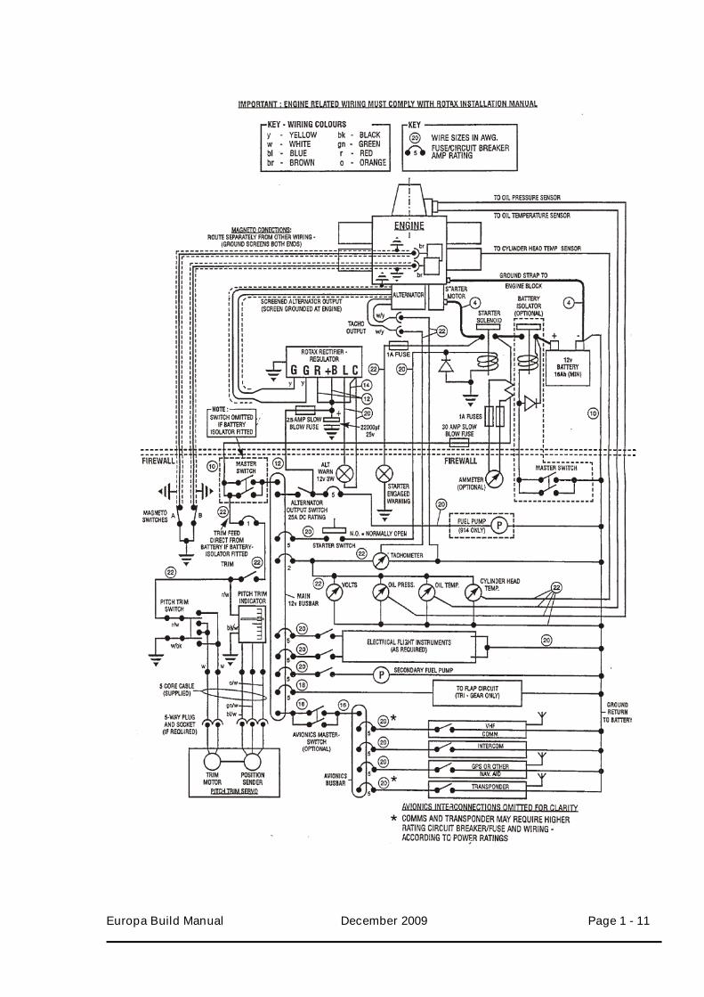
The wiring diagram at Figure 1 at the end of this chapter shows how you might connect the electricalsystem of a Europa with a Rotax 912. This section explains why each part of the circuit is arrangedthis way, and indicates some of the places where you can choose differently.
The first thing to know about the connections to the rest of the aircraft is that the 2 short brown leadscoming out of the ignition units must be connected to ground to stop the engine - magneto circuits arelive when the switches are open. Any good quality SPST switch (toggle, rocker or key-operated) canbe used, with a minimum rating of 250 volts/0.5 amp. It is important that screened cable is used toavoid electrical interference causing spurious triggering of the ignition; the screens should begrounded at both ends, and the cables routed away from other wiring - especially the alternatoroutput cables.
The alternator output comes through 2 yellow flexible cables (screened by metal braid grounded atthe engine end) from the left side of the ignition housing. These are connected to the 2 terminalsmarked ‘G’ on the rectifier/regulator, which can conveniently be mounted on the front of thefirewall. The output feed from the rectifier/regulator comes from the ‘+B’ terminal: it is linked to the‘R’ terminal, and connected to the positive side of the battery circuit through a 25 amp slow-blowfuse, with a 22000 µF 25V capacitor to ground. A slow blow fuse is a standard wire melt type orthermal circuit breaker. The fuse is there to prevent damage to the alternator/regulator system in theevent of an overload, while the capacitor is there to reduce the effect of electrical ‘spikes’ whichcould damage the regulator (especially if the output became disconnected from the battery, whichwould happen if the fuse blew).
Europa Build Manual December 2009 Page 1 - 5
A rugged polar aluminium electrolytic capacitor such as Radio Spares 105-408 is suitable, and isavailable from Europa Aviation, but make sure the ‘+’ terminal is connected to the regulator outputand ‘-’ to ground. The ‘C’ terminal is there to feed the busbar voltage to the regulator, and werecommend the fitting of a charge-indicating lamp between the ‘L’ and ‘C’ terminals.
The wire sizes shown in figure 1 comply with the Rotax recommendations for a minimum of 2.5 mm²for connections to terminals G, R, +B, and 1.5 mm² to C. We can use size 20 a.w.g. for the lampconnections because this should be adequate to take the 5 amp breaker current in the event of a fault,and the 12 volts 3w lamp would draw only 0.25 amp.
The starter solenoid is operated by a momentary contact switch fed via a breaker from the mainbusbar. A push switch or key-operated switch (which may be combined with the magneto switches,as “OFF-L-R-Both-Start” should be used, or a gated spring-loaded toggle (the gate is a cover toprevent inadvertent operation).
In the U.K. you are required by the CAA to fit a ‘starter-engaged’ warning light, which should beconnected to the starter motor side of the solenoid. Figure 1 shows a 1 amp in-line fuse to protect thewire.
The starter solenoid should be mounted on the firewall, and we recommend a diode across the coil toimprove reliability (this is now a requirement on certified aircraft). A small silicon rectifier diode,e.g. 1N5404, is appropriate and available from Europa Aviation. It will reduce sparking on the starterswitch contacts.
When fitting the diode, note that the symbol “points to positive” - if checked on a multimeter, it willshow a low resistance passing current in the direction of the arrow, but will block current the otherway.
Remember that the starter circuit draws very heavy currents, and good connections are needed tokeep the resistance low for good cranking. Use the correct size tinned copper ring-tongue crimps tofit each of the screwed terminals, with ferrule size to match the 4 a.w.g. cables. Prepare the cableends carefully, ensuring none of the copper wire strands is nicked while stripping the insulation andthat the length of each piece is the shortest which will avoid strain on the terminals (allowing formovements of the engine on its resilient mountings. If you do not have the right hydraulic crimpingpress for these terminals, you are strongly recommended to take the leads to the nearest aero-, auto-or agricultural shop that does, rather than solder them.
The ground return between the engine block and the battery negative terminal can be a tinned copperbraided earth strap of at least the same cross-section as the positive feed (minimum 16 mm²). You arestrongly recommended to provide the exposed positive battery and solenoid terminals withinsulating covers - neoprene sleeves or nipples are preferable to heat-shrink sleeving for thispurpose, as they can be re-used when removing and refitting the battery, and can be slid aside tocheck the terminals are tight.
Page 1 - 6 December 2009 Europa Build Manual
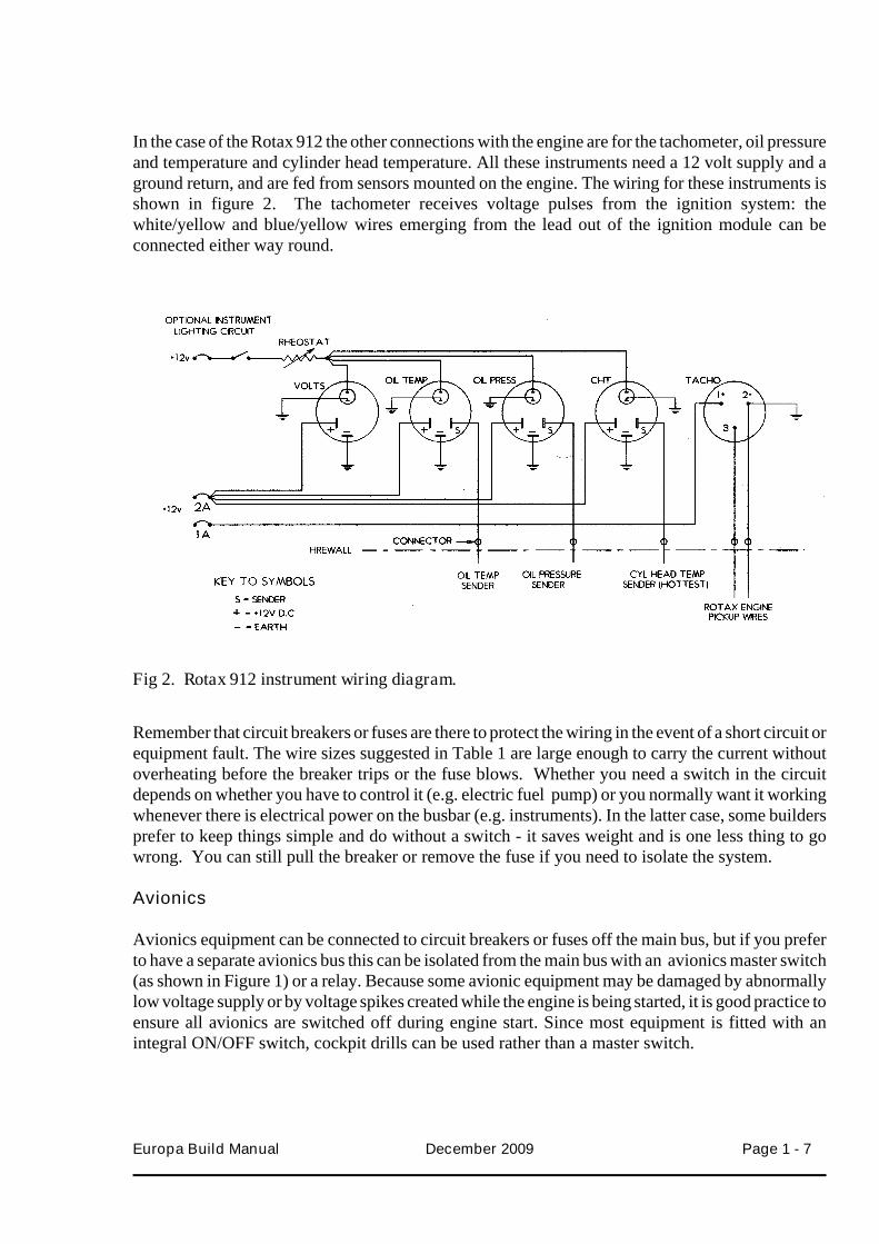
In the case of the Rotax 912 the other connections with the engine are for the tachometer, oil pressureand temperature and cylinder head temperature. All these instruments need a 12 volt supply and aground return, and are fed from sensors mounted on the engine. The wiring for these instruments isshown in figure 2. The tachometer receives voltage pulses from the ignition system: thewhite/yellow and blue/yellow wires emerging from the lead out of the ignition module can beconnected either way round.
Remember that circuit breakers or fuses are there to protect the wiring in the event of a short circuit orequipment fault. The wire sizes suggested in Table 1 are large enough to carry the current withoutoverheating before the breaker trips or the fuse blows. Whether you need a switch in the circuitdepends on whether you have to control it (e.g. electric fuel pump) or you normally want it workingwhenever there is electrical power on the busbar (e.g. instruments). In the latter case, some buildersprefer to keep things simple and do without a switch - it saves weight and is one less thing to gowrong. You can still pull the breaker or remove the fuse if you need to isolate the system.
Avionics
Avionics equipment can be connected to circuit breakers or fuses off the main bus, but if you preferto have a separate avionics bus this can be isolated from the main bus with an avionics master switch(as shown in Figure 1) or a relay. Because some avionic equipment may be damaged by abnormallylow voltage supply or by voltage spikes created while the engine is being started, it is good practice toensure all avionics are switched off during engine start. Since most equipment is fitted with anintegral ON/OFF switch, cockpit drills can be used rather than a master switch.
Europa Build Manual December 2009 Page 1 - 7
Fig 2. Rotax 912 instrument wiring diagram.
Avionic equipment is often designed to fit into a mounting tray, to the back of which all connectionsare made. Ensure that there is sufficient clearance between the back of the mounting tray and thefirewall for the connections to be made without the cables having to be bent at too tight a radius, orbeing in danger of chafing against the firewall.
VHF radio
For UK registered aircraft, a Certificate of Approval of Aircraft Radio Installation is required fromthe Civil Aviation Authority CAA). Application forms are available from the PFA who will issue arecommendation of approval to the CAA for correctly made installations.
Pitch trim
The MAC pitch trim servo is supplied complete with a double pole double throw (DPDT) rockerswitch and a position indicator for mounting on the panel or the top of the tunnel, together with asuitable length of 5-core cable for interconnection. We recommend that this trim circuit is connecteddirectly to the battery via a 1 amp breaker or fuse (as shown in figure 1). This will allow you tocontinue to use the trim in an emergency when you have switched off the master switch. The circuitbreaker must be of the pull-to-break type, otherwise a separate switch should be included so that thetrim circuit may be isolated quickly.
You may wish to fit a 5-way plug and socket (not supplied) to the trim servo, to make disconnectionand reconnection easier in the event that you have to remove and refit the servo. The colour-codedwiring should be connected in accordance with the MAC instructions supplied.
Clock
If you wish to fit a clock to your panel you should take a supply direct from the battery as for the trimcircuit : this is a good candidate for a fuse of very low rating (say 100 milliamps).
Ammeter
If you wish to fit an ammeter to show the rate at which the battery is being charged or discharged, youare recommended to use a type with a separate shunt located on the firewall. This avoids bringingheavy-duty cables which are live to the battery up to the instrument panel. The 22 a.w.g. leads to theinstrument can be protected by 1 amp in-line fuses on the firewall. The rating of the shunt shouldallow it to pass currents up to 25 to 50 amps, and the instrument should be calibrated to read ± 20amps or more, depending on the total load on your system.
Intercom
Some VHF radios are fitted with an integral intercom system, otherwise you may have a separateone. In either case, the wiring should be arranged together with each crew member’spress-to-transmit (PTT) switch so that when either person operates their PTT the other person’smicrophone is disconnected: this is to avoid intercom talk being transmitted over the R/T.
Page 1 - 8 December 2009 Europa Build Manual
We recommend installing the microphone and telephone jack sockets in the headrests or the cabinroof - this allows you to plug in your headsets in a convenient place without the leads getting in theway.
Another feature of an intercom worth considering is voice activation. Without voice activation theintercom will be permanently on, allowing engine noise to be always present in the earphones. Aseparate intercom switch could be used in this case of course.
Flydat option
The Rotax Flydat is available as an option to provide a display of all engine monitoring functions onone instrument, replacing the tachometer, oil temperature and pressure, and cylinder headtemperature gauges. In addition it can give a warning of exceeding preset values, and records valuesof parameters including engine running hours. The Flydat does not include voltage or ampsindication, and a voltmeter (or ammeter) should still be fitted.
All data is displayed digitally, not in conventional analogue form as with the separate instruments.
Master switch / solenoid
The master switch controls the connection between the power sources (battery and alternator output)and the main 12 volt busbar. The 10 a.w.g. feeder cable is protected by a 25 amp fuse on the firewall.It is shown in figure 2 as a DPST switch with both poles wired in parallel for increased reliability. Thecontacts should be rated at 12v DC / 20 amps.
We recommend the use of a master solenoid to isolate the battery, which must be acontinuously-rated type. The coil can be connected to the positive lead and operated by a mastercontrol switch in the cockpit to complete the circuit to ground (but make sure that if the coil isgrounded to the solenoid outer casing that this is isolated from the aircraft ground/ battery negative -otherwise the solenoid coil would have to be operated by a positive feed from the master switch).
Since the battery is mounted in the rear of the aircraft it is appropriate to install the master solenoidnext to it. This will enable you to isolate the heavy-duty feed to the engine compartment.
Load calculations
If you are fitting only the normal range of flight and engine instruments and basic avionics, there isno need to carry out any detailed load calculations because the power available from the enginealternator is sufficient to supply these loads and charge the battery at cruise RPM. If you want toinstall heavier loads such as lighting, you should calculate the total loading to see whether you needadditional power (such as the Rotax external generator option) or whether you can manage without.
Europa Build Manual December 2009 Page 1 - 9
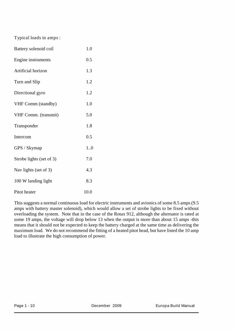
Typical loads in amps :
Battery solenoid coil 1.0
Engine instruments 0.5
Artificial horizon 1.3
Turn and Slip 1.2
Directional gyro 1.2
VHF Comm (standby) 1.0
VHF Comm. (transmit) 5.0
Transponder 1.8
Intercom 0.5
GPS / Skymap 1..0
Strobe lights (set of 3) 7.0
Nav lights (set of 3) 4.3
100 W landing light 8.3
Pitot heater 10.0
This suggests a normal continuous load for electric instruments and avionics of some 8.5 amps (9.5amps with battery master solenoid), which would allow a set of strobe lights to be fixed withoutoverloading the system. Note that in the case of the Rotax 912, although the alternator is rated atsome 19 amps, the voltage will drop below 13 when the output is more than about 15 amps -thismeans that it should not be expected to keep the battery charged at the same time as delivering themaximum load. We do not recommend the fitting of a heated pitot head, but have listed the 10 ampload to illustrate the high consumption of power.
Page 1 - 10 December 2009 Europa Build Manual
Europa Build Manual December 2009 Page 1 - 11

INTENTIONALLY BLANK
Page 1 - 12 December 2009 Europa Build Manual