24/7 EEG™ SUBQ - UNEEG medical
28
24/7 EEG™ SUBQ USER MANUAL FOR PROFESSIONALS
Transcript of 24/7 EEG™ SUBQ - UNEEG medical
24/7 EEG™ SUBQUSER MANUAL FOR PROFESSIONALS

USER MANUAL FOR PROFESSIONALS | ENGLISH | 3
24/7 EEG™ SubQ
PRODUCT OVERVIEW
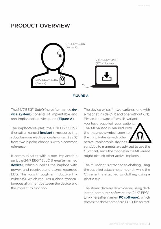
The 24/7 EEG™ SubQ (hereafter named de-vice system) consists of implantable and non-implantable device parts (Figure A).
The implantable part, the UNEEG™ SubQ (hereafter named implant), measures the subcutaneous electroencephalogram (EEG) from two bipolar channels with a common reference.
It communicates with a non-implantable part, the 24/7 EEG™ SubQ (hereafter named device), which supplies the implant with power, and receives and stores recorded EEG. This runs through an inductive link (wireless), which requires a close transcu-taneous alignment between the device and the implant to function.
The device exists in two variants; one with a magnet inside (M1) and one without (C1). Please be aware of which variant you have supplied your patient. The M1 variant is marked with the magnet-symbol seen to the right. Patients with other active implantable devices sensitive to magnets are advised to use the C1 variant, since the magnet in the M1 variant might disturb other active implants.
The M1 variant is attached to clothing using the supplied attachment magnet, while the C1 variant is attached to clothing using a plastic clip.
The stored data are downloaded using ded-icated computer software; the 24/7 EEG™ Link (hereafter named PC software), which parses the data to standard EDF+ file format.
FIGURE A
UNEEGTM SubQ (Implant)
24/7 EEGTM SubQ(Device)
24/7 EEG™ Link(PC software)
4 | USER MANUAL FOR PROFESSIONALS | ENGLISH
24/7 EEG™ SubQ
IMPORTANT: Additional warnings and pre-cautions may appear in this user manual.
WARNINGS • Seek medical guidance before entering
environments that could adversely affect the implant. This includes, but is not limited to:
- Hospital areas with restricted access for patients.
- High-power radio-frequency transmit-ters (e.g. military radar installations, ra-dio/TV transmitters).
• The implant is not compliant with the fol-lowing medical procedures. The implant must be explanted before receiving any of the following treatments:
- MRI scan. The implant is MR unsafe. - Therapeutic ionizing radiation induced
close to the implant (e.g. radiation therapy for cancer).
- Therapeutic ultrasound induced close to the implant.
- Electrical current induced close to the implant (e.g. electro knife, electrocon-vulsive therapy).
• The following medical procedures are safe to use with the implant:
- Diagnostic ionizing radiation (e.g. x-ray, CT).
- Diagnostic ultrasound.• Usage of the device closer than 30 cm
to other electronic equipment (including radio-frequency communications equip-ment) might result in improper operation. If such use is necessary, check that the device is functioning.
• Only supplied accessories may be con-nected to the device.
WARNINGS AND PRECAUTIONS
• Keep device and accessories out of reach of childeren.
PRECAUTIONSSubjects using the device should take note of the following:• The implant can be damaged if exposed
to physical impact. Do not take part in combat sports such as boxing, and wear a helmet in activities such as skiing, mountain bike riding, or horseback riding.
• The implant can be damaged if exposed to extreme pressure variations. Do not take part in extreme sport activities such as parachute jumping or diving deeper than 5 metres.
• In case the implant site has been ex-posed to physical injury, contact the responsible medical professional.
• Hold mobile phone to the opposite ear from the implant site.
• The device contains personal data. Take precautions not to lose the device.
• Do not wear the device in the shower or when swimming.
• Avoid dropping the device.• Do not use water or cleaning solutions
to clean the device. See User Manual for Home Use.
• Do not sink the device into any liquid, including alcohol.
• Do not try to open or repair the device.
USER MANUAL FOR PROFESSIONALS | ENGLISH | 5
24/7 EEG™ SubQ
1. INTRODUCTION . . . . . . . . . . . . . 6
1.1 Intended Use . . . . . . . . . . . . . .6
1.2 Contraindications . . . . . . . . . . .6
1.3 Side Effects. . . . . . . . . . . . . . .6
1.4 Important Subject Information . . .7
1.5 Implantation . . . . . . . . . . . . . .8
1.6 Sterility . . . . . . . . . . . . . . . . .8
2. HOW TO USE 24/7 EEG™ SubQ . . . 9
3. HOW TO INSTALL 24/7 EEG™ Link SOFTWARE . . . . . . . . . . . . . . .10
3.1 PC System Requirements . . . . . 10
3.2 Install 24/7 EEG™ Link . . . . . . . 10
4. HOW TO USE 24/7 EEG™ Link SOFTWARE . . . . . . . . . . . . 11
4.1 Connect Device to PC . . . . . . . 12
4.2 Connect Multiple Devices . . . . . 12
4.3 Download Data . . . . . . . . . . . 12
4.5 Device Error - Reset Device . . . . 13
4.6 Update Device . . . . . . . . . . . 14
4.7 Demonstrate Use . . . . . . . . . . 14
4.8 System Report . . . . . . . . . . . 14
4.9 Disconnect Device from PC. . . . 14
CONTENT
5. DATA INFORMATION. . . . . . . . . . 15
5.1 EDF+ Files . . . . . . . . . . . . . . 15
5.2 Auxiliary data . . . . . . . . . . . . 15
5.3 Metadata . . . . . . . . . . . . . . . 15
5.4 Data Specifications. . . . . . . . . 16
6. MAINTENANCE . . . . . . . . . . . . . 17
6.1 Storage and Handling. . . . . . . . 17
6.2 Lifetime of Implant . . . . . . . . . 17
6.3 Maintenance of Device. . . . . . . 17
6.4 Disposal . . . . . . . . . . . . . . . 17
6.5 Malfunctioning Devices . . . . . . 17
7. FEEDBACK PATTERNS. . . . . . . . . 18
8. TROUBLESHOOTING. . . . . . . . . . 19
9. TECHNICAL DESCRIPTION . . . . . 20
10. SYMBOLS AND MARKINGS . . . . 25
6 | USER MANUAL FOR PROFESSIONALS | ENGLISH
24/7 EEG™ SubQ
1. INTRODUCTION
1.1 INTENDED USEMeasuring and recording of electrical activ-ity of the brain (EEG) through electrodes implanted subcutaneously in the tissue be-tween the skull and the skin. Intended for subjects where single-location, continuous, ultra long-term (more than two weeks) EEG recordings are indicated to aid in monitoring and diagnosis of diseases or conditions that alter the EEG.
The intended users of the product are males and females, age 18 and above.
IMPORTANT: The subject should receive regular follow-up related to the system from the responsible medical professional.
1.2 CONTRAINDICATIONSThe device system is not intended in case of any of the following:• Subjects with cochlear implant(s).• Subjects involved in therapies with med-
ical devices that deliver electrical energy in the area around the implant.
• Subjects at high risk of surgical compli-cations, such as active systemic infection and hemorrhagic disease.
• Subjects who are unable (i.e. mentally or physically impaired patients), or do not have the necessary assistance, to proper-ly operate the device system.
• Subjects who have an infection at the site of device implantation.
• Subjects who operate MRI scanners.• Subjects with a profession/hobby that
includes activity imposing extreme pressure variations (e.g. diving or para-
chute jumping). NB: diving/snorkelling is allowed to 5 metres depth.
• Subjects with a profession/hobby that includes activity imposing an unaccept-able risk for trauma against the device or the site of implantation (e.g. martial art or boxing).
1.3 SIDE EFFECTSGeneral side effects normally associated with any surgical implantation procedure or local anaesthesia also apply to the place-ment of the implant.
Specifically, the following side effects may be associated with implantation and use of the device system:• Formation of haematoma or seroma
near the implant site following the surgical procedure (for a period up to 3 weeks).
• Temporary pain, headache, infection and discomfort (including soreness, inflam-mation, swelling, irritation and itching) at the implant site following the surgical procedure, for a period up to 3 weeks.
• Skin ischemia potentially inducing necrosis at the implant site due to pres-sure and compromised local circulation.
• Infection, swelling, soreness, irritation or itching of the skin at the implant site.
• Occasional headache or pain during long-term use of the device.
Note: 3M™ Cavilon™ or similar barrier film product can be used to protect against stress from the adhesive pad.
USER MANUAL FOR PROFESSIONALS | ENGLISH | 7
24/7 EEG™ SubQ
1.4 IMPORTANT SUBJECT INFORMATIONBelow is a list of important information for subjects using the 24/7 EEG™ SubQ.
• Inform subjects of risks, warnings and precautions for using the device as part of subject inclusion, see ‘WARNINGS AND PRECAUTIONS’ in the beginning of this user manual.
• Instruct subjects in the use of the device (see User Manual for Home Use for this information).
Note: The device will only collect data when it is turned on and connected to the implant. Disconnection will result in lacking data.
• Demonstrate the different feedback patterns of the device to the subject, see ‘4.7 Demonstrate Use’.
• Be sure that the subjects receive the User Manual for Home Use as well as all accessories necessary for using the device system (see User Manual for Home Use for information on the accessories).
8 | USER MANUAL FOR PROFESSIONALS | ENGLISH
24/7 EEG™ SubQ
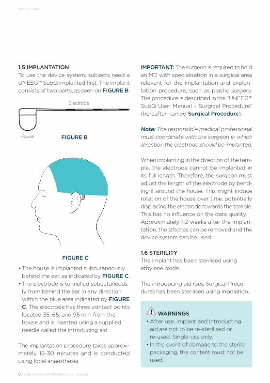
1.5 IMPLANTATIONTo use the device system, subjects need a UNEEG™ SubQ implanted first. The implant consists of two parts, as seen on FIGURE B.
• The house is implanted subcutaneously behind the ear, as indicated by FIGURE C.
• The electrode is tunnelled subcutaneous-ly from behind the ear in any direction within the blue area indicated by FIGURE C. The electrode has three contact points located 35, 65, and 95 mm from the house and is inserted using a supplied needle called the introducing aid.
The implantation procedure takes approxi- mately 15-30 minutes and is conducted using local anaesthesia.
FIGURE B
FIGURE C
Electrode
House
Electrode
House
IMPORTANT: The surgeon is required to hold an MD with specialisation in a surgical area relevant for the implantation and explan-tation procedure, such as plastic surgery. The procedure is described in the “UNEEG™ SubQ User Manual - Surgical Procedure” (hereafter named Surgical Procedure).
Note: The responsible medical professional must coordinate with the surgeon in which direction the electrode should be implanted.
When implanting in the direction of the tem-ple, the electrode cannot be implanted in its full length. Therefore, the surgeon must adjust the length of the electrode by bend-ing it around the house. This might induce rotation of the house over time, potentially displacing the electrode towards the temple. This has no influence on the data quality.Approximately 1-2 weeks after the implan-tation, the stitches can be removed and the device system can be used.
1.6 STERILITYThe implant has been sterilised using ethylene oxide.
The introducing aid (see Surgical Proce-dure) has been sterilised using irradiation.
WARNINGS • After use, implant and introducting
aid are not to be re-sterilised or re-used. Single-use only.
• In the event of damage to the sterile packaging, the content must not be used.
USER MANUAL FOR PROFESSIONALS | ENGLISH | 9
24/7 EEG™ SubQ
2. HOW TO USE 24/7 EEG™ SUBQ
For instructions on the daily use of the device, see the User Manual for Home Use provided separately.
To prepare the device for use, first connect it to a PC with EEG Link installed to synchro-nise the internal clock of the device. See ‘4.1 Connect Device to PC’.
If using one device for several subjects, it is recommended to clear the memory of the device in between the uses. See ‘4.4 Clear Memory’.
For instructions on how to demonstrate to the subject the various feedback patterns of the device, see ‘4.7 Demonstrate Use’.
10 | USER MANUAL FOR PROFESSIONALS | ENGLISH
24/7 EEG™ SubQ
3. HOW TO INSTALL 24/7 EEG™ LINK SOFTWARE
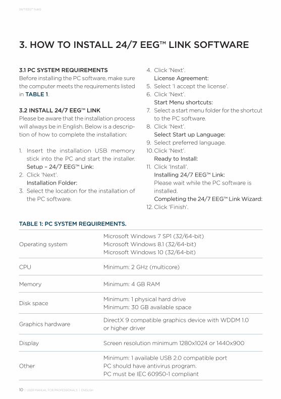
3.1 PC SYSTEM REQUIREMENTSBefore installing the PC software, make sure the computer meets the requirements listed in TABLE 1.
3.2 INSTALL 24/7 EEG™ LINKPlease be aware that the installation process will always be in English. Below is a descrip-tion of how to complete the installation:
1. Insert the installation USB memory stick into the PC and start the installer. Setup – 24/7 EEG™ Link:
2. Click ‘Next’. Installation Folder:3. Select the location for the installation of
the PC software.
Operating systemMicrosoft Windows 7 SP1 (32/64-bit)Microsoft Windows 8.1 (32/64-bit)Microsoft Windows 10 (32/64-bit)
CPU Minimum: 2 GHz (multicore)
Memory Minimum: 4 GB RAM
Disk spaceMinimum: 1 physical hard driveMinimum: 30 GB available space
Graphics hardwareDirectX 9 compatible graphics device with WDDM 1.0 or higher driver
Display Screen resolution minimum 1280x1024 or 1440x900
OtherMinimum: 1 available USB 2.0 compatible portPC should have antivirus program.PC must be IEC 60950-1 compliant
TABLE 1: PC SYSTEM REQUIREMENTS.
4. Click ‘Next’. License Agreement:5. Select ‘I accept the license’.6. Click ‘Next’. Start Menu shortcuts:7. Select a start menu folder for the shortcut
to the PC software.8. Click ‘Next’. Select Start up Language:9. Select preferred language.10. Click ‘Next’. Ready to Install:11. Click ‘Install’. Installing 24/7 EEG™ Link: Please wait while the PC software is
installed. Completing the 24/7 EEG™ Link Wizard:12. Click ‘Finish’.
USER MANUAL FOR PROFESSIONALS | ENGLISH | 11
24/7 EEG™ SubQ
4. HOW TO USE 24/7 EEG™ LINK SOFTWARE
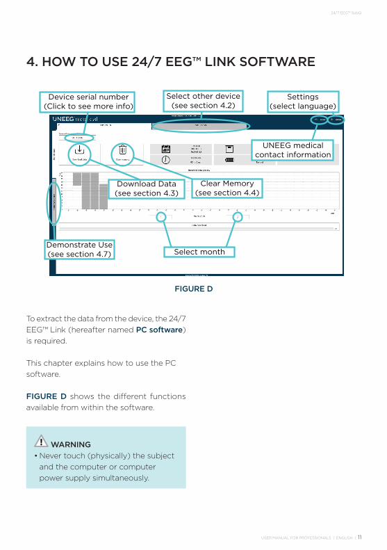
FIGURE D
Clear Memory(see section 4.4)
Select month
Select other device(see section 4.2)
Device serial number(Click to see more info)
UNEEG medicalcontact information
Settings(select language)
Download Data(see section 4.3)
Demonstrate Use(see section 4.7)
To extract the data from the device, the 24/7 EEG™ Link (hereafter named PC software) is required.
This chapter explains how to use the PC software.
FIGURE D shows the different functions available from within the software.
WARNING• Never touch (physically) the subject
and the computer or computer power supply simultaneously.
12 | USER MANUAL FOR PROFESSIONALS | ENGLISH
24/7 EEG™ SubQ
4.1 CONNECT DEVICE TO PCApart from the accessories for the subject, which are described in the User Manual for Home Use, the device system also comes with a special USB cable. The USB cable is needed to connect the device to the PC.
WARNING• Only use the supplied USB cable to
connect the device to the PC.
1. Start the PC software using the start menu shortcut created during installa-tion.
2. Insert the USB cable into the PC and into the device.
Note: When the device is connected to the PC, the internal clock of the device is syn-chronised with the PC. To make sure that data are correctly time stamped, the clock shall be synchronised within 30 days prior to data collection start.
Note: Make sure that the PC’s clock is correct when the device is connected to the PC.
Note: The device cannot record data while it is connected to the PC.
The feedback patterns of the device when connected to the PC are illustrated in ‘7 FEEDBACK PATTERNS’.
4.2 CONNECT MULTIPLE DEVICESTo handle data from several devices at the same time, it is possible to connect up to five different devices simultaneously while using the PC software.
1. To select another device, click the tab with the corresponding serial number (see Figure D on page 17).
4.3 DOWNLOAD DATAWhen the device has collected data from a subject, data can be downloaded to the PC.
Note: Data take up approximately 1 GB of storage per week of recording.
1. Connect device to PC (see ‘4.1 Connect Device to PC‘).
2. Click ‘Download data’.3. Select the destination folder and a file-
name prefix for the data.4. Click ‘Start data download’ and wait for
the data to download. Note: Do NOT disconnect the device or
turn off the PC while downloading data.5. When data are downloaded, select
whether to clear the memory of the de-vice. To do this at another time, see ‘4.4 Clear Memory‘.
6. To go directly to the downloaded data, click ‘Open Folder’.
USER MANUAL FOR PROFESSIONALS | ENGLISH | 13
24/7 EEG™ SubQ
4.4 CLEAR MEMORYThe memory storage allows for minimum 30 days of recording. When the storage is full, the device will stop recording.
To clear the memory of the device, follow these steps:1. Connect the device to the PC (see ‘4.1
Connect Device to PC’).2. Click ‘Clear memory’. The PC software
will inform about the last data download time.
Note: Make sure that all data are down-loaded before clearing memory of device.
3. Click ‘Clear memory’ and wait for the device to clear the memory
Note: Do NOT disconnect the device or turn off the PC while clearing the memory of the device.
4. When the device has finished clearing the memory, it is safe to disconnect the device
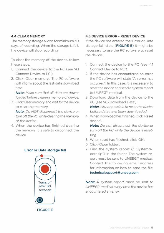
4.5 DEVICE ERROR - RESET DEVICEIf the device has entered the ‘Error or Data storage full’ state (FIGURE E) it might be necessary to use the PC software to reset the device.
1. Connect the device to the PC (see ‘4.1 Connect Device to PC’).
2. If the device has encountered an error, the PC software will state “An error has occurred”. In this case, it is necessary to reset the device and send a system report to UNEEG™ medical.
3. Download data from the device to the PC (see ‘4.3 Download Data‘).
Note: It is not possible to reset the device before data have been downloaded.
4. When download has finished, click ‘Reset device’.
Note: Do not disconnect the device or turn off the PC while the device is reset-ting.
5. When reset has finished, click ‘OK’.6. Click ‘Open folder’.7. Find the system report (“…Systemre-
port.zip”) in the folder. The system re-port must be sent to UNEEG™ medical. Contact the following email address for information on how to send the file: [email protected]
Note: A system report must be sent to UNEEG™ medical every time the device has encountered an error.
Error or Data storage full
FIGURE E
Error orData storage full
Fully chargedChargingVery low batteryLow battery
DisconnectedTurning on/o�
Sound
Signature
Vibration Turns offafter 3 min
Every30 min
Every 5 min
Once
Turns offafter 30seconds
14 | USER MANUAL FOR PROFESSIONALS | ENGLISH
24/7 EEG™ SubQ
4.6 UPDATE DEVICEThe PC software will automatically detect any available firmware updates for the device.
1. Before updating the device, the mem-ory must be cleared. Either download data (see ‘4.3 Download Data’) or clear the memory of the device (see ‘4.4 Clear Memory’).
2. After the memory has been cleared, the PC software will ask whether to update the firmware of the device. Click ‘Yes’.
3. Wait for the device to update. Note: Do not disconnect the device
or turn off the PC while the device is updating.
4. When update is finished, click ‘Continue’.
4.7 DEMONSTRATE USETo demonstrate the sounds and lights of the device, use the demonstration mode of the PC software.
1. Connect the device to the PC (see ‘4.1 Connect Device to PC’).
2. Click ‘Demonstrate use’. The power but-ton of the device will blink white twice to show that demo mode is activated.
3. To demonstrate the feedback pattern of one of the scenarios, click the corre-sponding button (e.g. “Low battery”).
4.8 SYSTEM REPORTA system report (…Systemreport.zip) is automatically generated every time data are downloaded from the device (see ‘4.3 Download Data’).
In case the device has encountered an error (see ‘4.5 Device Error - Reset Device’), please send the system report to UNEEG™ medical.For information regarding implant model and year of manufacture, send the system report to UNEEG™ medical and request the details.
4.9 DISCONNECT DEVICE FROM PC1. Make sure that the device is not down-
loading data (see ‘4.3 Download Data’), clearing memory (see ‘4.4 Clear Memo-ry’), resetting (see ‘4.5 Device Error - reset Device’) or updating (see ‘4.6 Update Device’).
2. Pull the USB cable out of the device. It is not necessary to ‘eject device’.
USER MANUAL FOR PROFESSIONALS | ENGLISH | 15
24/7 EEG™ SubQ
5. DATA INFORMATION
5.1 EDF+ FILESEEG data are parsed into EDF+ files. These files are annotated with status checks (short button presses) and dia-ry check marks (double button presses) performed by the subject. See the User Manual for Home Use for information about status check and diary check mark.
Be aware that the supplied PC Software is only capable of downloading the data from the device to the PC. To utilise the data, a third-party software program capable of handling EDF+ files must be installed.
Note: In case of any suspicion that the data are wrong/bad, verify the data with another measuring system.
5.2 AUXILIARY DATAThe device records auxiliary data in a proprietary file format that, if provided to UNEEG™ medical, can be interpreted to accelerometery recordings to support future product development.
5.3 METADATAMetadata are contained in the filename of the downloaded data. To make sure that the correct data are being analysed, it might be necessary to look at the metadata – e.g. to determine the serial number of the implant from which the data have been collected.
1. After data download (see ‘4.3 Down-load Data’), open the folder contain-ing the data.
The downloaded files will be named after this pattern:
EEG data file (EDF+):Prefix_Device_Implant_StartDate_FN_EEGdata.edf
System Report: Prefix_Device_Period_SystemReport.zip
Where the following applies:Prefix: Set by user
Device: 24/7 EEG™ SubQ Serial Number
Implant: Implant Serial Number
StartDate: Session start date [year, month, day]
Period: Start date and end date of data recording
FN: File Session Number*
* A new file session is started when: - The device is turned ON. - The device is disconnected from an
implant and connected to a new implant. - The device has recorded for 6 hours.
16 | USER MANUAL FOR PROFESSIONALS | ENGLISH
24/7 EEG™ SubQ
5.4 DATA SPECIFICATIONSSpecifications for the data are found in TABLE 2.
Sampling frequency
Bandwidth Resolution Accuracy Dynamic range
207 Hz 0.5-48 Hz < 1 µV +10% at 50 µV for all frequen-cies within 1 Hz to 48 Hz
+350 µV
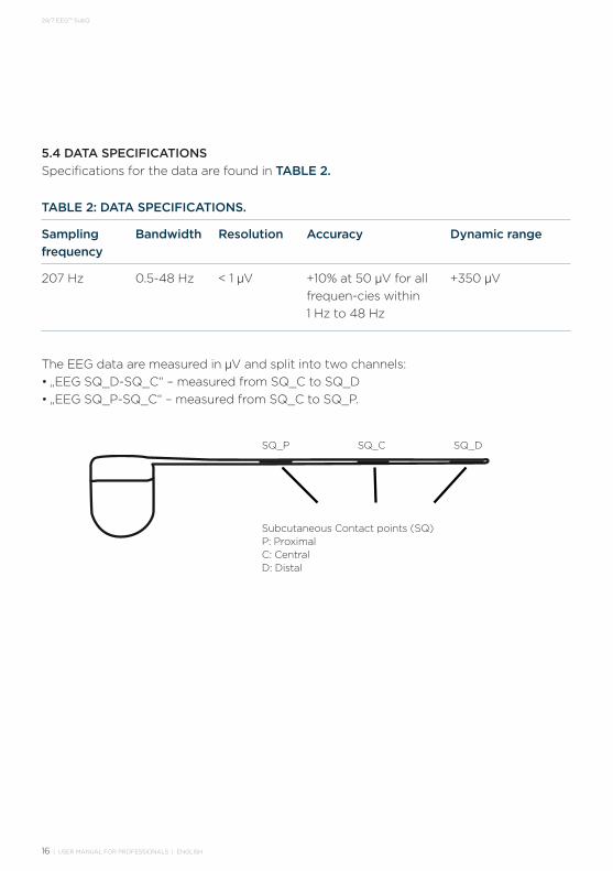
The EEG data are measured in µV and split into two channels:• „EEG SQ_D-SQ_C“ – measured from SQ_C to SQ_D• „EEG SQ_P-SQ_C“ – measured from SQ_C to SQ_P.
TABLE 2: DATA SPECIFICATIONS.
SQ_CSQ_P
Subcutaneous Contact points (SQ)P: ProximalC: CentralD: Distal
SQ_DSQ_P
Subcutaneous Contact points (SQ)P: ProximalC: CentralD: Distal
SQ_C SQ_D
USER MANUAL FOR PROFESSIONALS | ENGLISH | 17
24/7 EEG™ SubQ
See User Manual for Home Use for informa-tion on cleaning.
6.1 STORAGE AND HANDLINGStore the device within a temperature range of +5°C to +30°C.
Make sure that the device does not get wet, and, if necessary, dry it thoroughly with a cloth or similar.
PRECAUTION • Do not expose the device to water
or other liquids.• Avoid dropping the device.
6.2 LIFETIME OF IMPLANTThe implant has a lifetime of 15 months after implantation. Before this period expires, the implant must be explanted.
The implant does not require service or calibration during its lifetime.
6.3 MAINTENANCE OF DEVICEThe device does not need service or calibra-tion during its lifetime.
6. MAINTENANCE
6.4 DISPOSALThe device and all electronic accessories must be disposed of in accordance with the (WEEE) EU directive 2012/19/EU.
This means that the device and all electronic accessories should be handed in for recy-cling rather than discarded with household waste.
6.5 MALFUNCTIONING DEVICESIf a device is malfunctioning, first try to re-set the device, see ‘4.5 Device Error - Reset Device’. If this does not work, the malfunc-tioning device shall be returned to UNEEG™ medical.
In case an implant is not performing as ex-pected, it is recommended that UNEEG™ medical is consulted before explanting the implant. The malfunctioning implant shall be returned to UNEEG™ medical.
PRECAUTION • Never try to open or repair the
device.
18 | USER MANUAL FOR PROFESSIONALS | ENGLISH
24/7 EEG™ SubQ
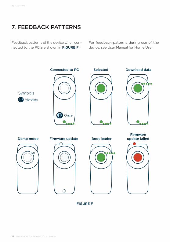
7. FEEDBACK PATTERNS
Feedback patterns of the device when con-nected to the PC are shown in FIGURE F.
Firmware update failedBoot loaderFirmware updateDemo mode
Download dataSelectedConnected to PC
Symbols
Vibration
FIGURE F
For feedback patterns during use of the device, see User Manual for Home Use.
Once
USER MANUAL FOR PROFESSIONALS | ENGLISH | 19
24/7 EEG™ SubQ
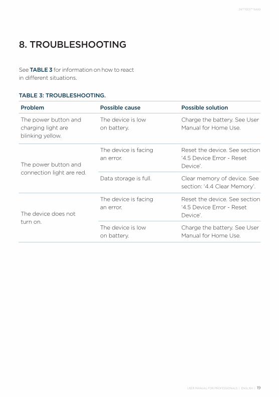
See TABLE 3 for information on how to react in different situations.
8. TROUBLESHOOTING
Problem Possible cause Possible solution
The power button and charging light are blinking yellow.
The device is low on battery.
Charge the battery. See User Manual for Home Use.
The power button and connection light are red.
The device is facing an error.
Reset the device. See section ‘4.5 Device Error - Reset Device’.
Data storage is full. Clear memory of device. See section: ‘4.4 Clear Memory’.
The device does not turn on.
The device is facing an error.
Reset the device. See section ‘4.5 Device Error - Reset Device’.
The device is low on battery.
Charge the battery. See User Manual for Home Use.
TABLE 3: TROUBLESHOOTING.
20 | USER MANUAL FOR PROFESSIONALS | ENGLISH
24/7 EEG™ SubQ
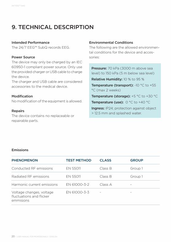
Intended PerformanceThe 24/7 EEG™ SubQ records EEG.
Power SourceThe device may only be charged by an IEC 60950-1 compliant power source. Only use the provided charger or USB cable to charge the device.The charger and USB cable are considered accessories to the medical device.
ModificationNo modification of the equipment is allowed.
RepairsThe device contains no replaceable or repairable parts.
9. TECHNICAL DESCRIPTION
Emissions
PHENOMENON TEST METHOD CLASS GROUP
Conducted RF emissions EN 55011 Class B Group 1
Radiated RF emissions EN 55011 Class B Group 1
Harmonic current emissions EN 61000-3-2 Class A -
Voltage changes, voltage fluctuations and flicker emmisions
EN 61000-3-3 - -
Pressure: 70 kPa (3000 m above sea level) to 150 kPa (5 m below sea level)
Relative Humidity: 10 % to 95 %
Temperature (transport): -10 °C to +55 °C (max 2 weeks)
Temperature (storage): +5 °C to +30 °C
Temperature (use): 0 °C to +40 °C
Ingress: IP24; protection against object > 12.5 mm and splashed water.
Environmental ConditionsThe following are the allowed environmen-tal conditions for the device and acces- sories:
USER MANUAL FOR PROFESSIONALS | ENGLISH | 21
24/7 EEG™ SubQ
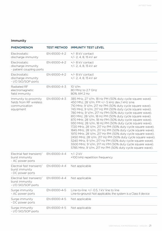
Immunity
PHENOMENON TEST METHOD IMMUNITY TEST LEVEL
Electrostatic discharge immunity
EN 61000-4-2 +/- 8 kV contact+/- 2, 4, 8, 15 kV air
Electrostatic discharge immunity - patient coupling ports
EN 61000-4-2 +/- 8 kV contact+/- 2, 4, 8, 15 kV air
Electrostatic discharge immunity - I/O SIO/SOP ports
EN 61000-4-2 +/- 8 kV contact+/- 2, 4, 8, 15 kV air
Radiated RF electromagnetic field immunity
EN 61000-4-3 10 V/m80 MHz to 2.7 GHz80% AM 2 Hz
Immunity to proximity fields from RF wireless communication equipment
EN 61000-4-3 385 MHz, 27 V/m, 18 Hz PM (50% duty cycle square wave).450 Mhz, 28 V/m, FM +/- 5 kHz dev.,1 kHz sine.710 MHz, 9 V/m, 217 Hz PM (50% duty cycle square wave).745 MHz, 9 V/m, 217 Hz PM (50% duty cycle square wave).780 MHz, 9 V/m, 217 Hz PM (50% duty cycle square wave).810 MHz, 28 V/m, 18 Hz PM (50% duty cycle square wave).870 MHz, 28 V/m, 18 Hz PM (50% duty cycle square wave).930 MHz, 28 V/m, 18 Hz PM (50% duty cycle square wave).1720 MHz, 28 V/m, 217 Hz PM (50% duty cycle square wave).1845 MHz, 28 V/m, 217 Hz PM (50% duty cycle square wave).1970 MHz, 28 V/m, 217 Hz PM (50% duty cycle square wave).2450 MHz, 28 V/m, 217 Hz PM (50% duty cycle square wave).5240 MHz, 9 V/m, 217 Hz PM (50% duty cycle square wave).5500 MHz, 9 V/m, 217 Hz PM (50% duty cycle square wave).5785 MHz, 9 V/m, 217 Hz PM (50% duty cycle square wave).
Electrial fast transient/ burst immunity - AC power ports
EN 61000-4-4 +/- 2 kV +100 kHz repetition frequency
Electrial fast transient/ burst immunity - DC power ports
EN 61000-4-4 Not applicable
Electrial fast transient/ burst immunity - I/O SIO/SOP ports
EN 61000-4-4 Not applicable
Surge immunity - AC power ports
EN 61000-4-5 Line-to-line: +/- 0.5, 1 kV line to lineLine-to-ground: Not applicable, the system is a Class II device
Surge immunity - DC power ports
EN 61000-4-5 Not applicable
Surge immunity - I/O SIO/SOP ports
EN 61000-4-5 Not applicable

22 | USER MANUAL FOR PROFESSIONALS | ENGLISH
24/7 EEG™ SubQ
PHENOMENON TEST METHOD IMMUNITY TEST LEVEL
Immunity to conducted disturbances induced by RF fields - AC power ports
EN 61000-4-6 3 V (6 V in ISN bands and amateur radio bandsa
0.15-80 MHz80% AM 2 Hz
Immunity to conducted disturbances induced by RF fields - DC power ports
EN 61000-4-6 Not applicable
Immunity to conducted disturbances induced by RF fields - I/O SIO/SOP ports
EN 61000-4-6 Not applicable
Immunity to conducted disturbances induced by RF fields - Patient coupling ports
EN 61000-4-6 Not applicable
Power frequency magnetic field immunity
EN 61000-4-8 30 A/m50 Hz
Voltage dips, short interruptions and voltage variations immunity
EN 61000-4-11 0% UT: 0.5 cycle at 0o, 90o, 135o, 180o, 225o, 270o and 315o
0% UT: 1 cycle at 0o
70% UT: 10 cycle at 0o
0% UT: 25 cycle at 0o
Electrical transient conduction along supply lines
ISO 7637-2 Not applicable
a The ISM (industrial, scientific and medical) bands between 0.15 MHz and 80 MHz are 6.765 MHz to 6.795 MHz; 13.553 MHz to 13.567 MHz; 26.957 MHz to 27.283 MHz; and 40.66 MHz to 40.70 MHz. The amateur radio bands between 0.15 MHz and 80 MHz are 1.8 MHz to 2.0 MHz. 3.5 MHz to 4.0 MHz. 5.3 MHZ to 5.4 MHz. 7 MHZ to 7.3 MHz. 10.1 MHz to 10.15 MHz. 14 MHz to 14.2 MHz. 18.07 MHz to 18.17 MHz. 21.0 MHZ to 21.4 MHz. 24.89 MHz to 24.99 MHz. 28.0 MHz to 29.7 MHz and 50.0 MHz to 54.0 MHz.
USER MANUAL FOR PROFESSIONALS | ENGLISH | 23
24/7 EEG™ SubQ
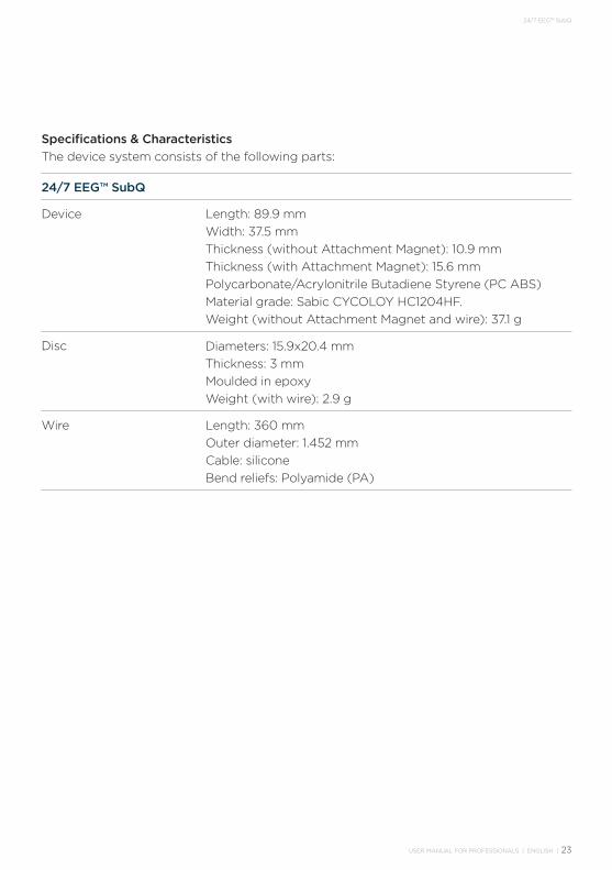
Specifications & CharacteristicsThe device system consists of the following parts:
24/7 EEG™ SubQ
Device Length: 89.9 mmWidth: 37.5 mmThickness (without Attachment Magnet): 10.9 mmThickness (with Attachment Magnet): 15.6 mmPolycarbonate/Acrylonitrile Butadiene Styrene (PC ABS)Material grade: Sabic CYCOLOY HC1204HF.Weight (without Attachment Magnet and wire): 37.1 g
Disc Diameters: 15.9x20.4 mmThickness: 3 mmMoulded in epoxyWeight (with wire): 2.9 g
Wire Length: 360 mmOuter diameter: 1.452 mmCable: siliconeBend reliefs: Polyamide (PA)
24 | USER MANUAL FOR PROFESSIONALS | ENGLISH
24/7 EEG™ SubQ
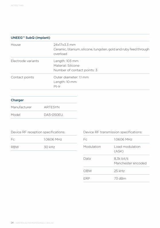
UNEEG™ SubQ (implant)
House 24x17x3.3 mmCeramic, titanium, silicone, tungsten, gold and ruby feed through overload
Electrode variants Length: 103 mmMaterial: SiliconeNumber of contact points: 3
Contact points Outer diameter: 1.1 mmLength: 10 mmPt-Ir
Device RF reception specifications:
Fc 1.0606 MHz
RBW 30 kHz
Manufacturer ARTESYN
Model DA5-050EU
Device RF transmission specifications:
Fc 1.0606 MHz
Modulation Load modulation (ASK)
Data 8,3k bit/s Manchester encoded
OBW 25 kHz
ERP 73 dBm
Charger
USER MANUAL FOR PROFESSIONALS | ENGLISH | 25
24/7 EEG™ SubQ
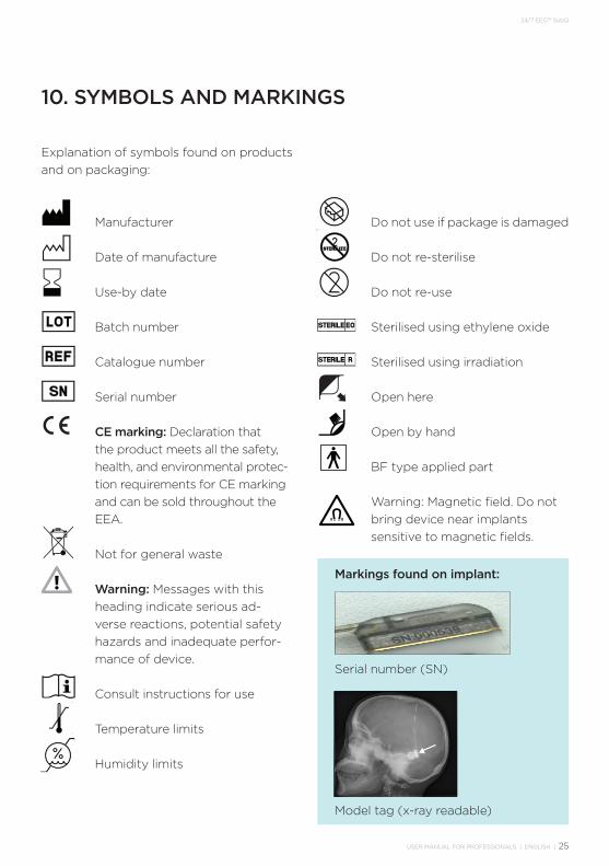
10. SYMBOLS AND MARKINGS
Explanation of symbols found on products and on packaging:
Manufacturer
Date of manufacture
Use-by date
Batch number
Catalogue number
Serial number
CE marking: Declaration that the product meets all the safety, health, and environmental protec-tion requirements for CE marking and can be sold throughout the EEA.
Not for general waste
Warning: Messages with this heading indicate serious ad-verse reactions, potential safety hazards and inadequate perfor-mance of device.
Consult instructions for use
Temperature limits
Humidity limits
Do not use if package is damaged
Do not re-sterilise
Do not re-use
Sterilised using ethylene oxide
Sterilised using irradiation
Open here
Open by hand
BF type applied part
Warning: Magnetic field. Do not bring device near implants sensitive to magnetic fields.
Markings found on implant:
Serial number (SN)
Model tag (x-ray readable)

26 | USER MANUAL FOR PROFESSIONALS | ENGLISH
24/7 EEG™ SubQ

USER MANUAL FOR PROFESSIONALS | ENGLISH | 27
24/7 EEG™ SubQ
Nymøllevej 63540 LyngeDenmark
www.uneeg.com
E-mail: [email protected]: +45 30 10 14 54
© 2020 UNEEG™ medical2020/06
Rev. IFU-10003-8
0344 2019


![NSF Project EEG CIRCUIT DESIGN. Micro-Power EEG Acquisition SoC[10] Electrode circuit EEG sensing Interference.](https://static.fdocuments.us/doc/165x107/56649cfb5503460f949ccecd/nsf-project-eeg-circuit-design-micro-power-eeg-acquisition-soc10-electrode.jpg)