24285 StudioLSeries Eng - jbl-tw.comjbl-tw.com/uploads/files/L-Series_OM_EN.pdf · weak bass and...
8
L810, L820, L830, L880, L890, LC1, LC2 STUDIO ™ L SERIES ® OWNER’S GUIDE
Transcript of 24285 StudioLSeries Eng - jbl-tw.comjbl-tw.com/uploads/files/L-Series_OM_EN.pdf · weak bass and...
L810, L820, L830, L880,L890, LC1, LC2
STUDIO™ L SERIES
®
OWNER’S GUIDE

2
1.5m–1.8m(5–6 ft.)
MODELS: L810 AND L830
SPEAKER PLACEMENTProper placement of thespeakers is an important stepin obtaining the most realisticsoundstage possible. Theserecommendations are for theoptimum placement of theloudspeakers. Use theseplacement recommendationsas a guide. Slight variationswill not diminish your listeningpleasure.
All of the Studio L Seriesloudspeakers referred to inthis guide are video-shielded
and may safely be placednear a television.
As front speakers
MODELS: L830, L880, L890
As surround speakers

3
Engl
ish
MODELS: LC1, LC2
The LC1 and LC2 centerchannel loudspeakers aredesigned to complement all ofthe Studio L Series loud-speakers. Either speaker isideal for re-creating thecinematic experience in yourhome.
MODEL: L820
The L820 loudspeakers aredesigned to be orientedhorizontally, as shown in theillustrations below. Although
these loudspeakers aredesigned as a mirrored pair,the decision as to which oneis left or right will depend on
the amount of space leftbetween them.
A wider stereo image is presented with the tweeter/midrange array outboard, anda tighter image is presentedwith the array inboard.
This placement provides awide spread in sound,supplemented by the centerchannel speaker.
0-0,6m(0-2ft)
For stereo-only applications:
For home theater applications:
Less than 1,8m-2,4m (6-8 feet)
Less than 1,8m-2,4m (6-8 feet)

Speakers and electronicshave corresponding (+) and(–) terminals. It is important toconnect both speakersidentically: (+) on the speakerto (+) on the amplifier and (–)on the speaker to (–) on theamplifier. Wiring “out ofphase” results in thin sound,weak bass and poor imaging.
To use the binding-postspeaker terminals, unscrewthe colored collar until thepass-through hole in thecenter post is visible. Insertthe bare end of the wirethrough this hole; then screwthe collar down until theconnection is tight.
The hole in the center of eachcollar is intended for use withbanana-type connectors. Tocomply with European CE certification, these holes areblocked with plastic inserts atthe point of manufacture. Touse banana-type connectorsrequires the removal of theinserts. Do not remove theseinserts if you are using theproduct in an area covered bythe European CE certification.
BI-WIRING
The bi-wire connectionmethod requires one amplifierand two sets of speaker wires.By removing the shortingbars, connections may bemade to the individual networksections using four conductors,one for each of the fourterminals.
For single-wire connection,leave the shorting bars inplace and connect only asingle set of speaker wires(two conductors) to the twoupper terminals.
SPEAKER CONNECTIONS
4
MODELS: L810,L820, L830, LC1,LC2
The supplied self-adhesiverubber feet may be attached tothe bottom corners of yourspeakers to protect yourfurniture.
MODELS: L880,L890
These models feature fourrubber feet that enable themto be placed on a smooth-surfaced floor, such as tile orhardwood. Four metal spikesare supplied for use when thespeaker is to be placed on acarpeted surface, to decouplethe speaker from the floor andprevent unwanted damping.To insert the spikes, gently laythe speaker on its side (not its
front or back) on a soft,nonabrasive surface. Eachspike screws into the threadedinsert in the center of eachrubber foot. Make sure allfour spikes are screwed incompletely for stability.
NEVER drag the speaker tomove it, as this will damagethe spikes, the feet and/or thewood cabinet itself. Alwayslift the speaker and carry it toits new location.
SPEAKER SETUP
– +
– +
– +Amplifier
High Frequency
Low Frequency
Bi-Wire Connections
– +
– +
Receiver’s Speaker Outputs
– +– +
– +
LEFT
LEFT
RIGHT
RIGHT
– +
MODELS: L810,L820, L830, L880,L890
MODELS: LC1,LC2
Receiver’s Speaker Outputs
Place pads here
Right Left
Right Left
Center
CenterAmplifier
High Frequency
Place pads here
Engl
ish
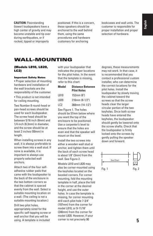
(Models L810, L820,LC2)
Important Safety Notes • Proper selection of mountinghardware and installation ofthe wall brackets are theresponsibility of the customer.
• This product is not intendedfor ceiling mounting.
Two Number 8 round-head orpan-head screws should beused for each loudspeaker.The screw head should bebetween 5/16 inch (8mm) and1/4 inch (6.3mm) in diameter,and the screw should be atleast 2 inches (50mm) inlength.
When installing screws in anywall, it is always preferable toscrew them into a wall stud. Ifnone is available, it isimportant to always useproperly selected wallanchors.
Attach two of the four self-adhesive rubber pads thatcame with the loudspeaker tothe back of the enclosure inthe two bottom corners sothat the cabinet is spacedevenly from the wall. Select asuitable mounting location ona wall. (The ceiling is not asuitable mounting location.)
Drill two pilot holes,appropriately sized for thespecific self-tapping screw orwall anchor that you will beusing. A template is included
with your loudspeaker thatindicates the proper locationsfor the pilot holes. In the eventthat the template is missing,refer to this chart:
Model Distance BetweenPilot Holes
L810 152mm (6")
L820 216mm (8-1/2")
LC2 368mm (14-1/2")
See Figure 1. The holesshould be 57mm below whereyou want the top of theenclosure to be positioned.Use a carpenter’s level toensure that the holes areeven and that the speaker willmount on the level.
Install the two screws intoeither a wooden wall stud oranchor, and tighten them untilthe back of each screw headis about 1/8" (3mm) from thewall. See Figure 2.
Models L810 and L820 mayalso be corner-mounted usingthe keyholes located on thebezeled corners. For cornermounting, fold the mountingtemplate in half, place the foldin the corner at the desiredheight, and use the outerholes. In case the template ismissing, for corner mountingdrill each pilot hole 7-3/4"(197mm) from the corner formodel L810, or 9-11/16"(246mm) from the corner formodel L820. However, if yourcorner is not precisely 90
degrees, these measurementsmay not work. In that case, itis recommended that youcontact a professional custominstaller, who can determinethe correct locations for thepilot holes. Install theloudspeaker by slowly movingthe cabinet toward thescrews so that the screwheads clear the largercircular portion of the twokeyholes. Once both screwheads have entered thekeyholes, the loudspeakershould gently be lowered ontothe screw shafts. Check thatthe loudspeaker is firmlylocked onto the screws bygently pulling the speakerdown and forward.
WALL-MOUNTING
See Chart 3mm(1/8")
5
CAUTION: Floorstanding(tower) loudspeakers have ahigh center of gravity and maybecome unstable and tip overduring earthquakes, or ifrocked, tipped or improperly
positioned. If this is a concern,these speakers should beanchored to the wall behindthem, using the sameprocedures and hardwarecustomary for anchoring
bookcases and wall units. Thecustomer is responsible forproper installation and properselection of hardware.
Fig. 1 Fig. 2
See Chart
6
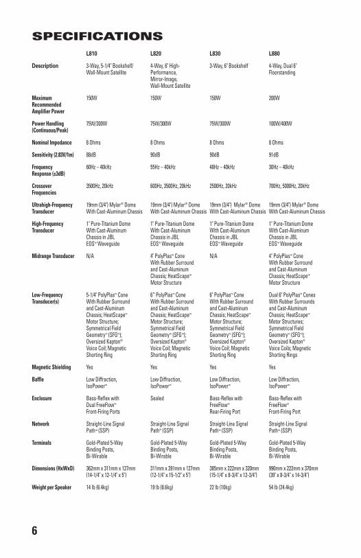
SPECIFICATIONS L810 L820 L830 L880
Description 3-Way, 5-1/4" Bookshelf/ 4-Way, 6" High- 3-Way, 6" Bookshelf 4-Way, Dual 6"Wall-Mount Satellite Performance, Floorstanding
Mirror-Image,Wall-Mount Satellite
Maximum 150W 150W 150W 200WRecommendedAmplifier Power
Power Handling 75W/300W 75W/300W 75W/300W 100W/400W(Continuous/Peak)
Nominal Impedance 8 Ohms 8 Ohms 8 Ohms 8 Ohms
Sensitivity (2.83V/1m) 88dB 90dB 90dB 91dB
Frequency 60Hz – 40kHz 55Hz – 40kHz 48Hz – 40kHz 30Hz – 40kHzResponse (±3dB)
Crossover 3500Hz, 20kHz 600Hz, 3500Hz, 20kHz 2500Hz, 20kHz 700Hz, 5000Hz, 20kHzFrequencies
Ultrahigh-Frequency 19mm (3/4") Mylar® Dome 19mm (3/4") Mylar® Dome 19mm (3/4") Mylar® Dome 19mm (3/4") Mylar® DomeTransducer With Cast-Aluminum Chassis With Cast-Aluminum Chassis With Cast-Aluminum Chassis With Cast-Aluminum Chassis
High-Frequency 1" Pure-Titanium Dome 1" Pure-Titanium Dome 1" Pure-Titanium Dome 1" Pure-Titanium DomeTransducer With Cast-Aluminum With Cast-Aluminum With Cast-Aluminum With Cast-Aluminum
Chassis in JBL Chassis in JBL Chassis in JBL Chassis in JBLEOS™ Waveguide EOS™ Waveguide EOS™ Waveguide EOS™ Waveguide
Midrange Transducer N/A 4" PolyPlas™ Cone N/A 4" PolyPlas™ ConeWith Rubber Surround With Rubber Surround and Cast-Aluminum and Cast-Aluminum Chassis; HeatScape™ Chassis; HeatScape™
Motor Structure Motor Structure
Low-Frequency 5-1/4" PolyPlas™ Cone 6” PolyPlas™ Cone 6" PolyPlas™ Cone Dual 6" PolyPlas™ ConesTransducer(s) With Rubber Surround With Rubber Surround With Rubber Surround With Rubber Surrounds
and Cast-Aluminum and Cast-Aluminum and Cast-Aluminum and Cast-AluminumChassis; HeatScape™ Chassis; HeatScape™ Chassis; HeatScape™ Chassis; HeatScape™
Motor Structure; Motor Structure; Motor Structure; Motor Structures; Symmetrical Field Symmetrical Field Symmetrical Field Symmetrical Field Geometry™ (SFG™); Geometry™ (SFG™); Geometry™ (SFG™); Geometry™ (SFG™); Oversized Kapton® Oversized Kapton® Oversized Kapton® Oversized Kapton®
Voice Coil; Magnetic Voice Coil; Magnetic Voice Coil; Magnetic Voice Coils; MagneticShorting Ring Shorting Ring Shorting Ring Shorting Rings
Magnetic Shielding Yes Yes Yes Yes
Baffle Low Diffraction, Low Diffraction, Low Diffraction, Low Diffraction, IsoPower™ IsoPower™ IsoPower™ IsoPower™
Enclosure Bass-Reflex with Sealed Bass-Reflex with Bass-Reflex withDual FreeFlow™ FreeFlow™ FreeFlow™
Front-Firing Ports Rear-Firing Port Front-Firing Port
Network Straight-Line Signal Straight-Line Signal Straight-Line Signal Straight-Line SignalPath™ (SSP) Path™ (SSP) Path™ (SSP) Path™ (SSP)
Terminals Gold-Plated 5-Way Gold-Plated 5-Way Gold-Plated 5-Way Gold-Plated 5-Way Binding Posts, Binding Posts, Binding Posts, Binding Posts,Bi-Wirable Bi-Wirable Bi-Wirable Bi-Wirable
Dimensions (HxWxD) 362mm x 311mm x 127mm 311mm x 391mm x 127mm 385mm x 222mm x 320mm 990mm x 222mm x 370mm(14-1/4" x 12-1/4" x 5") (12-1/4" x 15-1/2" x 5") (15-1/4" x 8-3/4" x 12-3/4") (39" x 8-3/4" x 14-3/4")
Weight per Speaker 14 lb (6.4kg) 19 lb (8.6kg) 22 lb (10kg) 54 lb (24.4kg)

7
Engl
ish
L890 LC1 LC2
Description 4-Way, Dual 8" Floorstanding 3-Way, Dual 5-1/4" Center 4-Way, Dual 6" Wall-Mount Center
Maximum 250W 150W 150WRecommendedAmplifier Power
Power Handling 125W/500W 75W/300W 75W/300W(Continuous/Peak)
Nominal Impedance 8 Ohms 8 Ohms 8 Ohms
Sensitivity (2.83V/1m) 91dB 91dB 92dB
Frequency 28Hz – 40kHz 55Hz – 40kHz 50Hz – 40kHzResponse (±3dB)
Crossover 700Hz, 5000Hz, 20kHz 3000Hz, 20kHz 700Hz, 4000Hz, 20kHzFrequencies
Ultrahigh-Frequency 19mm (3/4") Mylar® Dome 19mm (3/4") Mylar® Dome 19mm (3/4") Mylar® DomeTransducer With Cast-Aluminum Chassis With Cast-Aluminum Chassis With Cast-Aluminum Chassis
High-Frequency 1" Pure-Titanium Dome 1" Pure-Titanium Dome 1" Pure-Titanium DomeTransducer With Cast-Aluminum With Cast-Aluminum With Cast-Aluminum
Chassis in JBL Chassis in JBL Chassis in JBLEOS™ Waveguide EOS™ Waveguide EOS™ Waveguide
Midrange Transducer 4" PolyPlas™ Cone N/A 4" PolyPlas™ ConeWith Rubber Surround With Rubber Surroundand Cast-Aluminum and Cast-Aluminum Chassis; HeatScape™ Chassis; HeatScape™
Motor Structure Motor Structure
Low-Frequency Dual 8" PolyPlas™ Cones Dual 5-1/4" PolyPlas™ Cones Dual 6" PolyPlas™ ConesTransducer(s) With Rubber Surrounds With Rubber Surrounds With Rubber Surrounds
and Cast-Aluminum and Cast-Aluminum and Cast-AluminumChassis; HeatScape™ Chassis; HeatScape™ Chassis; HeatScape™
Motor Structures; Motor Structures; Motor Structures;Symmetrical Field Symmetrical Field Symmetrical Field Geometry™ (SFG™); Geometry™ (SFG™); Geometry™ (SFG™); Oversized Kapton® Oversized Kapton® Oversized Kapton®
Voice Coils; Magnetic Voice Coils; Magnetic Voice Coils; MagneticShorting Rings Shorting Rings Shorting Rings
Magnetic Shielding Yes Yes Yes
Baffle Low Diffraction, Low Diffraction, Low Diffraction, IsoPower™ IsoPower™ IsoPower™
Enclosure Bass-Reflex With Bass-Reflex With SealedFreeFlow™ FreeFlow™
Front-Firing Port Rear-Firing Port
Network Straight-Line Signal Straight-Line Signal Straight-Line SignalPath™ (SSP) Path™ (SSP) Path™ (SSP)
Terminals Gold-Plated 5-Way Gold-Plated 5-Way Gold-Plated 5-WayBinding Posts, Binding Posts, Binding Posts,Bi-Wirable Bi-Wirable Bi-Wirable
Dimensions (HxWxD) 1075mm x 259mm x 380mm 191mm x 534mm x 254mm 311mm x 559mm x 127mm(42-1/4" x 10-1/4" x 15") (7-1/2" x 21" x 10") (12-1/4" x 22" x 5")
Weight per Speaker 27,5kg (60 lb) 10.5kg (23 lb) 13,2kg (29 lb)

* Trademarks of Dolby Laboratories.DTS is a registered trademark of Digital Theater Systems, Inc.Mylar and Kapton are registered trademark of E.I. du Pont de Nemours and Company.
** The maximum recommended amplifier power rating will ensure proper system headroom to allow for occasional peaks. We do not recommend sustained operation at these maximum power levels.All features and specifications are subject to change without notice.All dimensions include grilles and feet, but not spikes.
© 2005 Harman International Industries, Incorporated. All rights reserved.
JBL is a registered trademark of Harman International Industries, Incorporated.
Part No.353334-001
PRO SOUND COMES HOME™
JBL Consumer Products, 250 Crossways Park Drive, Woodbury, NY 11797 USA8500 Balboa Boulevard, Northridge, CA 91329 USA, phone 516-255-4JBL (USA only)
2, route de Tours, 72500 Chateau-du-Loir, Francewww.jbl.com
TROUBLESHOOTINGIf there is no sound fromany of the speakers:
• Check that receiver/ampli-fier is on and that a source isplaying.
• Review proper operation ofyour receiver/amplifier.If there is no soundcoming from onespeaker:
• Check the “Balance” control on your receiver/amplifier.
• Check all wires andconnections betweenreceiver/ amplifier andspeakers.
• Make sure no wires aretouching other wires orterminals and creating a shortcircuit.
• Make sure all wires areconnected. Make sure noneof the speaker wires arefrayed, cut or punctured.
• In Dolby* Digital or DTS®
modes, make sure that thereceiver/processor isconfigured so that thespeaker in question isenabled.
• Turn off all electronics andswitch the speaker inquestion with one of the otherspeakers that is workingcorrectly. Turn everythingback on, and determinewhether the problem hasfollowed the speakers, or hasremained in the samechannel. If the problem is inthe same channel, the sourceof the problem is most likelywith your receiver or
amplifier, and you shouldconsult the owner’s manual forthat product for furtherinformation. If the problem hasfollowed the speaker, consultyour dealer for furtherassistance or, if that is notpossible, visit www.jbl.comfor further information.If the system plays at lowvolumes but shuts off asvolume is increased:
• Check all wires andconnections betweenreceiver/ amplifier andspeakers.
• Make sure all wires areconnected. Make sure noneof the speaker wires arefrayed, cut or punctured.
• If more than one pair of mainspeakers is being used, checkthe minimum impedancerequirements of yourreceiver/amplifier.If there is no (or low)bass output:
• Make sure the polarities (+ and –) of the left and right“Speaker Inputs” areconnected properly.
• Consider adding a poweredsubwoofer to your system foruse with digital “.1” surroundformats.
If there is no sound from the surround speakers:
• Check all wires andconnections betweenreceiver/ amplifier andspeakers. Make sure all wiresare connected. Make surenone of the speaker wires arefrayed, cut, punctured ortouching each other.
• Review proper operation ofyour receiver/amplifier and itssurround sound features.
• Make sure the movie or TVshow you are watching isrecorded in a surround soundmode. If it is not, check to seewhether your receiver/amplifier has other surroundmodes you may use.
• In Dolby Digital or DTS modes,make sure your receiver/processor is configured so thatthe surround speakers areenabled.
• Review the operation of yourDVD player and the jacket ofyour DVD to make sure that theDVD features the desired DolbyDigital or DTS mode, and thatyou have properly selected thatmode using both the DVDplayer’s menu and the DVDdisc’s menu.
Declaration of Conformity
We, Harman Consumer Group International2, route de Tours 72500 Chateau-du-LoirFrance
declare in own responsibility that the productsdescribed in this owner’s manual are in compliancewith technical standards:
EN 61000-6-3:2001EN 61000-6-1:2001
Laurent RaultHarman Consumer Group International
Chateau-du-Loir, France 4/05