24 RIGGING Polypropylene and Nylon Rope crane hook, the supporting legs of the sling may not be...
9
24-1 Equipment CHAPTER 24 RIGGING 24 RIGGING Tradespeople who are not professional riggers must nonetheless rig loads at times on the job. Carpenters, for instance, are often involved not only in handling but in hoisting and landing material. When in doubt about rigging, consult your supervisor. Information in this chapter covers only the basics of rigging. Rigging Inspection Checklist Use this checklist to inspect rigging components regularly and before each lift. Manila Rope* Dusty residue when twisted open Indicates wear from inside out and overloading. Replace rope if damage is extensive. Broken strands, fraying, spongy texture Replace rope. Wet Use caution. Strength of rope could be reduced. Frozen Thaw and dry at room temperature. Mildew or dry rot Replace rope. Dry and brittle Do not oil. Wash with cold water and hang in coils to dry. Polypropylene and Nylon Rope Chalky exterior appearance Indicates overexposure to sunlight (UV) rays. Possibly left unprotected outside. Do not use. Discard. Dusty residue when twisted open Indicates wear from inside out. Replace rope if damage is extensive. Frayed exterior Abraded by sharp edges. Use caution. Strength of rope could be reduced. Broken strands Destroy and discard. Cold or frozen Thaw, dry at room temperature before use. Reduction in size Usually indicates overloading and excessive wear. Use caution. Reduce capacity accordingly. Wire Rope (Figure 24-1) Rusty, lack of lubrication Apply light, clean oil. Do not use engine oil. Excessive outside wear Used over rough surfaces with misaligned or wrong sheave sizes. Reduce load capacity according to wear. If outside diameter of wire is more than 1/3 worn away, replace rope. Broken wires Up to six allowed in one rope lay, OR three in one strand in one rope lay, with no more than one at an attached fitting. Otherwise, destroy and replace rope. Crushed, jammed, or flattened strands Replace rope. Bulges in rope Replace, especially non- rotating types. Gaps between strands Replace rope. Core protrusion Replace rope. Heat damage, torch burns, or electric arc strikes Replace rope. Frozen rope Do not use. Avoid sudden loading of cold rope. Kinks, bird- caging Replace rope. Destroy defective rope. Polypropylene and Nylon Web Slings Chalky exterior appearance Overexposed to sunlight (UV) rays. Should be checked by manufacturer.
Transcript of 24 RIGGING Polypropylene and Nylon Rope crane hook, the supporting legs of the sling may not be...
24-1Equipment
CHAPTER 24 RIGGING
24 RIGGING
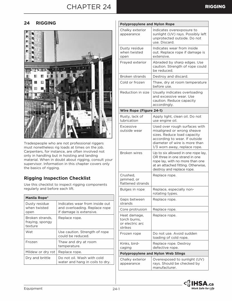
Tradespeople who are not professional riggers must nonetheless rig loads at times on the job. Carpenters, for instance, are often involved not only in handling but in hoisting and landing material. When in doubt about rigging, consult your supervisor. Information in this chapter covers only the basics of rigging.
Rigging Inspection ChecklistUse this checklist to inspect rigging components regularly and before each lift.
Manila Rope*
Dusty residue when twisted open
Indicates wear from inside out and overloading. Replace rope if damage is extensive.
Broken strands, fraying, spongy texture
Replace rope.
Wet Use caution. Strength of rope could be reduced.
Frozen Thaw and dry at room temperature.
Mildew or dry rot Replace rope.
Dry and brittle Do not oil. Wash with cold water and hang in coils to dry.
Polypropylene and Nylon Rope
Chalky exterior appearance
Indicates overexposure to sunlight (UV) rays. Possibly left unprotected outside. Do not use. Discard.
Dusty residue when twisted open
Indicates wear from inside out. Replace rope if damage is extensive.
Frayed exterior Abraded by sharp edges. Use caution. Strength of rope could be reduced.
Broken strands Destroy and discard.
Cold or frozen Thaw, dry at room temperature before use.
Reduction in size Usually indicates overloading and excessive wear. Use caution. Reduce capacity accordingly.
Wire Rope (Figure 24-1)
Rusty, lack of lubrication
Apply light, clean oil. Do not use engine oil.
Excessive outside wear
Used over rough surfaces with misaligned or wrong sheave sizes. Reduce load capacity according to wear. If outside diameter of wire is more than 1/3 worn away, replace rope.
Broken wires Up to six allowed in one rope lay, OR three in one strand in one rope lay, with no more than one at an attached fitting. Otherwise, destroy and replace rope.
Crushed, jammed, or flattened strands
Replace rope.
Bulges in rope Replace, especially non-rotating types.
Gaps between strands
Replace rope.
Core protrusion Replace rope.
Heat damage, torch burns, or electric arc strikes
Replace rope.
Frozen rope Do not use. Avoid sudden loading of cold rope.
Kinks, bird-caging
Replace rope. Destroy defective rope.
Polypropylene and Nylon Web Slings
Chalky exterior appearance
Overexposed to sunlight (UV) rays. Should be checked by manufacturer.

24-2 Construction Health and Safety Manual
RIGGING
*Manila rope is not recommended for construction use and is illegal for lifelines and lanyards.†Use only alloy steel for overhead lifting. Chain repairs are best left to the manufacturer. Chains beyond repair should be cut with a torch into short pieces.
Polypropylene and Nylon Web Slings (cont'd)
Frayed exterior Could have been shock-loaded or abraded. Inspect very carefully for signs of damage.
Breaks, tears, or patches
Destroy. Do not use.
Frozen Thaw and dry at room temperature before use.
Contaminated with oil
Destroy.
Wire Rope Slings
Broken wires Up to six allowed in one rope lay or three in one strand in one rope lay with no more than one at an attached fitting. Otherwise, destroy and replace rope.
Kinks, bird-caging Replace and destroy.
Crushed and jammed strands
Replace and destroy.
Core protrusion Replace and destroy.
Bulges in rope Replace and destroy.
Gaps between strands
Replace and destroy.
Wire rope clips Check proper installation and tightness before each lift. Remember, wire rope stretches when loaded, which may cause clips to loosen.
Attached fittings Check for broken wires. Replace and destroy if one or more are broken.
Frozen Do not use. Avoid sudden loading of cold ropes to prevent failure.
Sharp bends Avoid sharp corners. Use pads such as old carpet, rubber hose, or soft wood to prevent damage.
Chain Slings†
Elongated or stretched links
Return to manufacturer for repair.
Failure to hang straight
Return to manufacturer for repair.
Bent, twisted, or cracked links
Return to manufacturer for repair.
Gouges, chips, or scores
Ground out and reduce capacity according to amount of material removed.
Replace wire rope if there are– 6 or more broken wires in one lay– 3 or more broken wires in one
strand in one lay– 3 or more broken wires in one lay
in standing ropes.
Estimate rope’s condition at section showing maximum deterioration.
Core protrusion as a result of torsional unbalance created by shock loading.
Protrusion of core resulting from shock loading.
Figure 24-1: Wire Rope Inspection
WornSection
Enlarged View of Single Strand
Where the surface wires are worn by 1/3 or more of their diameter, the rope must be replaced.
Multi-strand rope "bird cages" due to torsional unbalance. Typical of build-up seen at anchorage end of multi-fall crane application.
A "bird cage" caused by sudden release of tension and resultant rebound of rope from overloaded condition. These strands and wires will not return to their original positions.
HardwareKnow what hardware to use, how to use it, and how its working load limits (WLLs) compare with the rope or chain used with it.
All fittings must be of adequate strength for the application. Only forged alloy steel load-rated hardware should be used for overhead lifting. Load-rated hardware is stamped with its WLL (Figure 24-2).
Figure 24-2: Forged Alloy Hook with Stamped Capacity

24-3Equipment
RIGGING
Inspect hardware regularly and before each lift. Telltale signs include
• Wear• Cracks• Severe corrosion• Deformation/bends• Mismatched parts• Obvious damage.
Any of these signs indicates a weakened component that should be replaced for safety. Figure 24-3 shows what to check for on a hook.
Check for wearand deformation.
Check for signsof opening up.
Check for wear
and cracks.
Check forcracks
andtwisting.
Figure 24-3: Hook Inspection Areas
Sling ConfigurationsThe term "sling" includes a wide variety of configurations for all fibre ropes, wire ropes, chains, and webs. The most commonly used types in construction are explained here.
Single Vertical Hitch
The total weight of the load is carried by a single leg (Figure 24-4). This configuration must not be used for lifting loose material, long material, or anything difficult to balance. This hitch provides absolutely no control over the load because it permits rotation.
Figure 24-4: Single Vertical Hitch
Bridle Hitch
Two, three, or four single hitches can be used together to form a bridle hitch (Figure 24-5). They provide excellent stability when the load is distributed equally among the legs, when the hook is directly over the centre of gravity of the load, and the load is raised level. The leg length may need adjustment with turnbuckles to distribute the load.
Detail
Figure 24-5: Bridle Hitch
Caution: Load may be carried by only 2 legs while 3rd and 4th merely balance it.
Single Basket Hitch
This hitch is ideal for loads with inherent stabilizing characteristics. The load is automatically equalized, with each leg supporting half the load (Figure 24-6). Do not use on loads that are difficult to balance because the load can tilt and slip out of the sling.
Figure 24-6: Single Basket Hitch
Double Basket Hitch
Consists of two single basket hitches passed under the load (Figure 24-7). The legs of the hitches must be kept far enough apart to provide balance without opening excessive sling angles.
60° or more
Figure 24-7: Double Basket Hitch

24-4 Construction Health and Safety Manual
RIGGING
Double Wrap Basket Hitch
This is a basket hitch that is wrapped completely around the load (Figure 24-8). This method is excellent for handling loose materials, pipes, rods, or smooth cylindrical loads because the rope or chain exerts a full 360-degree contact with load and tends to draw it together.
Figure 24-8: Double Wrap Basket Hitch
Single Choker Hitch
This forms a noose in the rope and tightens as the load is lifted (Figure 24-9). It does not provide full contact and must not be used to lift loose bundles or loads that are difficult to balance.
Figure 24-9: Single Choker Hitch
Double Choker Hitch
Consists of two single chokers attached to the load and spread to provide load stability (Figure 24-10). Does not grip the load completely but can balance the load. Can be used for handling loose bundles.
Figure 24-10: Double Choker Hitch
Double Wrap Choker Hitch
The rope or chain is wrapped completely around the load before being hooked into the vertical part of the sling (Figure 24-11). Makes full contact with load and tends to draw it together. If the double wrap choker is incorrectly made and the two eyes are placed on the crane hook, the supporting legs of the sling may not be equal in length and the load may be carried by one leg only. Do not run the sling through the hook, permitting an unbalanced load to tip.
Figure 24-11: Double Wrap Choker Hitch
Braided Slings
Fabricated from six or eight small diameter ropes braided together to form a single rope that provides a large bearing surface, tremendous strength, and flexibility in all directions (Figure 24-12). They are very easy to handle and almost impossible to kink. Especially useful for basket hitches where low bearing pressure is desirable or where the bend is extremely sharp.
Figure 24-12: Braided Slings
Metal (Wire or Chain) Mesh Slings
Well adapted for use where loads are abrasive, hot, or tend to cut fabric or wire rope slings (Figure 24-13).
Figure 24-13: Metal Mesh Slings

24-5Equipment
RIGGING
Chain Slings
Made for abrasion and high temperature resistance (Figure 24-14). The only chain suitable for lifting is grade 80 or 100 alloy steel chain. Grade 80 chain is marked with an 8, 80, or 800. Grade 100 is marked with a 10, 100, or 1000. The chain must be embossed with this grade marking every 3 feet or 20 links, whichever is shorter—although some manufacturers mark every link. Chain must be padded on sharp corners to prevent bending stresses.
Figure 24-14: Chain Slings
Wire Rope Slings
The use of wire rope slings for lifting materials provides several advantages over other types of slings. While not as strong as chain, it has good flexibility with minimum weight. Outer wires breaking warn of failure and allow time to react. Properly fabricated wire rope slings are very safe for general construction use.
On smooth surfaces, the basket hitch should be snubbed against a step or change of contour to prevent the rope from slipping as the load is applied (Figure 24-15). The angle between the load and the sling should be approximately 60 degrees or greater to avoid slippage (Figure 24-7).
WRONG Legs will slide
together.
RIGHT
Figure 24-15: Wire Rope Slings
On wooden boxes or crates, the rope will dig into the wood sufficiently to prevent slippage. On other rectangular loads, the rope should be protected by guards or load protectors at the edges to prevent kinking.
Loads should not be allowed to turn or slide along the rope during a lift. The sling or the load may become scuffed or damaged. Use a double choker if the load must turn.
Hooking Up• Avoid sharp bends, pinching, and kinks in rigging
equipment. Thimbles should be used at all times in sling eyes.
• Never wrap a wire rope sling completely around a hook. The tight radius will damage the sling.
• Make sure the load is balanced in the hook. Eccentric loading can reduce capacity dangerously.
• Never point-load a hook unless it is designed and rated for such use (Figure 24-16).
• Never wrap the crane hoist rope around the load. Attach the load to the hook by slings or other rigging devices adequate for the load.
• Avoid bending the eye section of wire rope slings around corners. The bend will weaken the splice or swaging.
• Avoid bending wire rope slings near any attached fitting.
• Understand the effect of sling angle on sling load (Figure 24-17) and pull angle on beam load (Figure 24-18).
Figure 24-16: Point-Loading a Hook Severely Reduces Capacity
1000 LBS 1000 LBS
707 L
BS 1000 LBS
500
LBS
577
LBS
45o 30o
60o
MinimumRecommended
Best Good
AVOID
500
LBS 577 LBS
1000 LBS707 LBS
1000 LBS 1000 LBS
Figure 24-17: Effect of Sling Angle on Sling Load

24-6 Construction Health and Safety Manual
RIGGING
Angle of pull affects load on beam.
Angle Load onof Pull Beam 90° 200 lbs60° 187 lbs45° 171 lbs
90° 60° 45°
100 lbs
Figure 24-18: Effect of Pull Angle on Beam Load
Basic Knots and HitchesEvery worker should be able to tie the basic knots and hitches that are useful in everyday work.
Two Half Hitches
Figure 24-19: Two Half Hitches
Two half hitches, which can be quickly tied, are reliable and can be put to almost any general use (Figure 24-19).
Figure 24-20: Round Turn and Two Half Hitches
Round Turn and Two Half Hitches
Used to secure loads to be hoisted horizontally. Two are usually required because the load can slide out if lifted vertically (Figure 24-20).
Timber Hitch and Two
Figure 24-21: Timber Hitch and Two Half Hitches
Half Hitches
A good way to secure a scaffold plank for hoisting vertically. The timber hitch grips the load (Figure 24-21).
Reef or Square Knot
Can be used for tying two ropes of the same diameter together. It is unsuitable for wet or slippery ropes and should be used with caution since it unties easily when either free end is jerked. Both live and dead ends of the rope must come out of the loops at the same side (Figure 24-22).
Figure 24-22: Reef or Square Knot
Bowline
If properly tied, this is a universal knot that never jams or slips (Figure 24-23). Two interlocking bowlines can be used to join two ropes together. Single bowlines can be used for hoisting or hitching directly around a ring or post.
Figure 24-23: Bowline
Sheet Bend
This type of knot can be used for tying ropes of light to medium size size (Figure 24-24).
Single Sheet Bend Double Sheet Bend
Figure 24-24: Sheet Bends
Running Bowline
The running bowline is mainly used for hanging objects with ropes of different diameters. The weight of the object determines the tension necessary for the knot to grip. Follow the directions below as shown in Figure 24-25.

24-7Equipment
RIGGING
1 2
4
3
Figure 24-25: Running Bowline(1) Make an overhand loop with the end of the rope held toward you.
(2) Hold the loop with your thumb and fingers and bring the standing part of the rope back so that it lies behind the loop.
(3) Take the end of the rope in behind the standing part, bring it up, and feed it through the loop.
(4) Pass it behind the standing part at the top of the loop and bring it back down through the loop.
Table 24-1: WLL of Wire Rope Slings
Table 24-2: Weights of Materials (Based on Volume)‡
MaterialApproximate Weight (lb per cu ft)
MaterialApproximate Weight (lb per cu ft)
METALS TIMBER, AIR-DRYAluminum 165 Cedar 22Brass 535 Fir, Douglas, seasoned 34Bronze 500 Fir, Douglas, seasoned 40Copper 560 Fir, Douglas, wet 50Iron 480 Fir, Douglas, glue laminated 34Lead 710 Hemlock 30Steel 480 Pine 30Tin 460 Poplar 30MASONRY Spruce 28Ashlar masonry 140-160 LIQUIDSBrick masonry, soft 110 Alcohol, pure 49Brick masonry, common Gasoline 42 (about 3 tons per thousand) 125 Oils 58Brick masonry, pressed 140 Water 62Clay tile masonry, average 60 EARTHRubble masonry 130-155 Earth, wet 100Concrete, cinder, taydite 100-110 Earth, dry (about 2050Concrete, slag 130 lb per cu yd) 75Concrete, stone 144 Sand and gravel, wet 120Concrete, stone, reinforced Sand and gravel, dry 105 (4050 lb per cu yd) 150 River sand (about 3240ICE AND SNOW lb per cu yd) 120Ice 56 VARIOUS BUILDINGSnow, dry, fresh fallen 8 MATERIALSSnow, dry, packed 12-25 Cement, portland, loose 94Snow, wet 27-40 Cement, portland, set 183MISCELLANEOUS Lime, gypsum, loose 53-64Asphalt 80 Mortar, cement-time, set 103Tar 75 Crushed rock (about 2565Glass 160 lb per cu yd) 90-110
Table 24-3: Drywall Weights‡
Non-Fire Rated 8' 10' 12'
1/2" 58 lb 72 lb 86 lb5/8" 74 lb 92 lb 110 lb
Fire-Rated
1/2" 64 lb 80 lb 96 lb5/8" 77 lb 96 lb 115 lb
Table 24-4: Weights of Steel Studs and Trims‡ Pcs./Bdl. lb (perSTUD SIZE (.018 thickness) 1,000 Lin. Ft.)1 5/8 All Lengths 10 2902 1/2 All Lengths 10 3403 5/8 All Lengths 10 4156 (.020) All Lengths 10 625
TRACK SIZES (.018 THICKNESS)1 5/8 Regular Leg 10 2402 1/2 Regular Leg 10 2953 5/8 Regular Leg 10 3656 (.020) Regular Leg 10 5701 5/8 2 Leg 12 3652 1/2 2 Leg 6 4153 5/8 2 Leg 6 470
DRYWALL FURRING CHANNELElectro-Galvanized 10 300
DRYWALL CORNER BEAD1 1/4 x 1 1/4 Various 120
RESILIENT CHANNEL Electro-Galvanized 20 210DRYWALL TRIMS1/2 Door & Windows L. 20 1005/8 Door & Window L. 20 1003/8 Casing Bead J. 20 1101/2 Casing Bead J. 20 1205/8 Casing Bead J. 20 130DRYWALL ANGLE1 x 2 Drywall Angle 10 200
‡NOTE: These tables contain sample values for the purposes of illustration only. Refer to the manufacturer of the material or equipment you’re using for precise values.

24-8 Construction Health and Safety Manual
RIGGING
Table 24-5: Weights of Materials (Based on Surface Area)‡
Material
Approximate Weight Lbs. Per Square
Foot
Material
Approximate Weight Lbs. Per Square
Foot
CEILINGS FLOORING (Per Inch of Thickness) (Per Inch of Thickness)Plaster board 5 Hardwood 5Acoustic and fire resistive tile 2 Sheathing 2.5Plaster, gypsum-sand 8 Plywood, fir 3Plaster, light aggregate 4 Wood block, treated 4Plaster, cement sand 12 Concrete, finish or fill 12ROOFING Mastic base 12Three-ply felt and gravel 5.5 Mortar base 10Five-ply felt and gravel 6.5 Terrazzo 12.5Three-ply felt, no gravel 3 Tile, vinyl 1/8 inch 1.5Five-ply felt, no gravel 4 Tile, linoleum 3/16 inch 1Shingles, wood 2 Tile, cork, per 1/16 inch 0.5Shingles, asbestos 3 Tile, rubber or asphalt 3/16 inch 2Shingles, asphalt 2.5 Tile, ceramic or quarry 3/4 inch 11Shingles, 1/4 inch slate 10 Carpeting 2Shingles, tile 14 DECKS AND SLABSPARTITIONS Steel roof deck 1 1/2" - 14 ga. 5Steel partitions 4 - 16 ga. 4Solid 2" gypsum-sand plaster 20 - 18 ga. 3Solid 2" gypsum-light agg. plaster 12 - 20 ga. 2.5Metal studs, metal lath, 3/4" - 22 ga. 2 plaster both sides 18 Steel cellular deck 1 1/2" - 12/12 ga. 11Metal or wood studs, plaster - 14/14 ga. 8 board and 1/2" plaster both sides 18 - 16/16 ga. 6.5Plaster 1/2" 4 - 18/18 ga. 5Hollow clay tile 2 inch 13 - 20/20 ga. 3.5
3 inch 16 Steel cellular deck 3" - 12/12 ga. 12.54 inch 18 - 14/14 ga. 9.55 inch 20 - 16/16 ga. 7.56 inch 25 - 18/18 ga. 6
Hollow slag concrete block 4 in 24 - 20/20 ga. 4.56 in 35 Concrete, reinforced, per inch 12.5
Hollow gypsum block 3 inch 10 Concrete, gypsum, per inch 54 inch 13 Concrete, lightweight, per inch 5-105 inch 15.5 MISCELLANEOUS6 inch 16.5 Windows, glass, frame 8
Solid gypsum block 2 inch 9.5 Skylight, glass, frame 123 inch 13 Corrugated asbestos 1/4 inch 3.5
MASONRY WALLS Glass, plate 1/4 inch 3.5(Per 4 Inch of Thickness) Glass, common 1.5Brick 40 Plastic sheet 1/4 inch 1.5Glass brick 20 Corrugated steel sheet, galv.Hollow concrete block 30 - 12 ga. 5.5Hollow slag concrete block 24 - 14 ga. 4Hollow cinder concrete block 20 - 16 ga. 3Hollow haydite block 22 - 18 ga. 2.5Stone, average 55 - 20 ga. 2Bearing hollow clay tile 23 - 22 ga. 1.5
Wood Joists - 16" ctrs. 2 x 12 3.52 x 10 32 x 8 2.5
Steel plate (per inch of thickness) 40
Table 24-6: Weights of Suspended Ceiling Grid Systems‡
Systems Qty./Ctn. (Lin. Ft.) Lbs./Ctn. (Lbs.)NON-FIRE RATED GRID SYSTEM1 1/2 x 144" Main Runner 240 581 x 48" Cross Tee 300 551 x 24" Cross Tee 150 281 x 30" Cross Tee 187.5 351 x 20" Cross Tee 125 231 x 12" Cross Tee 75 14
FIRE-RATED GRID SYSTEM1 1/2 x 144" Main Runner 240 701 1/2 x 48" Cross Tee 240 701 1/2" x 24" Cross Tee 120 35
WALL MOULDINGSWall Mould 3/4 x 15/16 x 120" 400 49Reveal Mould 3/4 x 3/4 x 1/2 x 3/4 x 120" 200 36
ACCESSORIESHold-Down Clips (for 5/8" tile) 500 pcs. 3
BASKETWEAVE & CONVENTIONAL 5’ x 5’ MODULE – NON RATED1 1/2 x 120" Main Member 200 491 1/2 x 60" Cross Tee 250 61Wall Mould 3/4 x 15/16 x 120" 400 57
THIN LINE GRID SYSTEM – NON-RATEDMain Runner 1 1/2 x 144" 300 65Cross Tee 1 1/2 x 48" 300 65Cross Tee 1 1/2 x 24" 150 33Wall Mould 15/16 x 9/16 x 120" 500 62Reveal Mould 1 x 3/8 x 3/8 x 9/16 x 120" 300 48Main Runner 1 1/12 x 144" 300 65Cross Tee 1 1/2 x 48" 300 65Cross Tee 1 1/2 x 24" 150 33Wall Mount 15/16 x 9/16 x 120" 500 62
Hand Signals for Hoisting Operations
These hand signals are available to order as pocket-sized cards. Go to the ihsa.ca website and search for Hand Signals for Hoisting Operations Card (V002).
‡NOTE: These tables contain sample values for the purposes of illustration only. Refer to the manufacturer of the material or equipment you’re using for precise values.

24-9Equipment
RIGGING
For Cranes Operating "On Outriggers"
For Crawler-Mounted Cranes or When Lifting "On Rubber"
Rigging Safety Tips
With two or more slings on a hook, use a shackle.
Use tag lines for control.
Block loose loads before unhooking.
Make sure loads are secure.
Stay back when slings are pulled out from under loads.