2.3 The Non-Inverting Configuration - KU ITTCjstiles/412/handouts/2.3 The Non...2/18/2011 The...
12
2/18/2011 section 2_3 The non inverting configuration 1/1 Jim Stiles The Univ. of Kansas Dept. of EECS 2.3 The Non-Inverting Configuration Reading Assignment: pp. Another standard op-amp circuit configuration is the non-inverting configuration. HO: THE NON-INVERTING CONFIGURATION An important non-inverting circuit is the voltage vollower. HO: THE VOLTAGE FOLLOWER
Transcript of 2.3 The Non-Inverting Configuration - KU ITTCjstiles/412/handouts/2.3 The Non...2/18/2011 The...

2/18/2011 section 2_3 The non inverting configuration 1/1
Jim Stiles The Univ. of Kansas Dept. of EECS
2.3 The Non-Inverting Configuration
Reading Assignment: pp.
Another standard op-amp circuit configuration is the non-inverting configuration.
HO: THE NON-INVERTING CONFIGURATION An important non-inverting circuit is the voltage vollower.
HO: THE VOLTAGE FOLLOWER

2/18/2011 The NonInverting Configuration lecture 1/4
Jim Stiles The Univ. of Kansas Dept. of EECS
The Non-Inverting Configuration Recall that v- =v+ (the virtual short) ALWAYS for feedback amplifiers.
Good heavens! The inverting input (v+) of this configuration is not at virtual ground (i.e., 0v+ ≠ )!
+
-
vin
vout ideal
R2 R1
v-
v+
i1 i2 i- =0
i+ =0

2/18/2011 The NonInverting Configuration lecture 2/4
Jim Stiles The Univ. of Kansas Dept. of EECS
No virtual ground here! Notice also that for the circuit above, the voltage at the non-inverting terminal is the input voltage vin :
0inv v−∴ = ≠ We use this fact to analyze this non-inverting configuration. First, we use KCL to determine that:
1 2i i i−= +
and since 0i− = , we again find that:
1 2i i=
and from Ohm’s Law:
1 21 1 1
0 outv vv vi iR R R
−− − −− −= = =
+
-
vin
vout ideal
R2 R1
v-
v+
i1 i2 i- =0
i+ =0

2/18/2011 The NonInverting Configuration lecture 3/4
Jim Stiles The Univ. of Kansas Dept. of EECS
i- = 0 is the key These results are of course very similar to the expressions we derived when analyzing the inverting configuration. The main difference is of course that v- is not equal to zero. Instead, we know that inv v− = . Thus:
1 21 1
in in outv v vi iR R− −
= =
and since 1 2i i= , we determine a relationship involving vin and vout only:
1 2
in in outv v vR R− −
=
+
-
vin
vout ideal
R2 R1
v-
v+
i1 i2 i- =0
i+ =0

2/18/2011 The NonInverting Configuration lecture 4/4
Jim Stiles The Univ. of Kansas Dept. of EECS
Note the gain is a positive number Performing some simple algebra, we rearrange this expression and find the open-circuit voltage gain of the non-inverting configuration:
2
1
1ocout
voin
v RAv R
= = +
Note that the open-circuit voltage gain for this configuration is a positive number. We conclude then that the input and output voltage will have the same sign (i.e.,± ). This is why we call the configuration non-inverting.

2/18/2011 The Voltage Follower lecture 1/7
Jim Stiles The Univ. of Kansas Dept. of EECS
The Voltage Follower The voltage follower has a open-circuit voltage gain 1voA = —with the result that
out inv v= ! A: To see why the voltage follower is important, consider the following example.
+
-
vin out inv v=
ideal
R
Q: Pfft! The output voltage is equal to the input voltage?! Why even bother?
2/18/2011 The Voltage Follower lecture 2/7
Jim Stiles The Univ. of Kansas Dept. of EECS
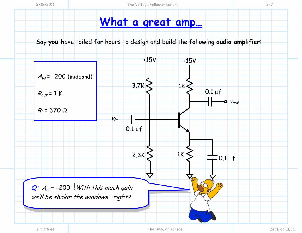
What a great amp… Say you have toiled for hours to design and build the following audio amplifier:
+15V +15V
1K 3.7K
1K 2.3K
0.1 μf
0.1 μf
0.1 μf
vout
vin
Avo = -200 (midband) Rout = 1 K Ri = 370 Ω
Q: 200 voA = − !With this much gain we’ll be shakin the windows—right?

2/18/2011 The Voltage Follower lecture 3/7
Jim Stiles The Univ. of Kansas Dept. of EECS
…or, maybe not A: Actually, if we connected this amplifier directly to a speaker, nothing would happen—silence! A: The reason for this is that the resistance of most speakers is very small (4 Ω-8 Ω).
Q: ???

2/18/2011 The Voltage Follower lecture 4/7
Jim Stiles The Univ. of Kansas Dept. of EECS
What’s the problem then? We can use the linear equivalent circuit model of the audio amplifier to analyze the result:
.4200 0 84 1000out in inv v v⎛ ⎞= − = −⎜ ⎟+⎝ ⎠
The output of this amplifier is even smaller than its input! The problem, of course, is not that the open-circuit voltage gain is too small—after all, it’s –200!
+ -
370Ω
1K
200 inv− + vin -
+ vout -
vin
4Ω

2/18/2011 The Voltage Follower lecture 5/7
Jim Stiles The Univ. of Kansas Dept. of EECS
The output resistance is just too large! The problem is that the amplifier output resistance (Rout = 377Ω) is much larger than the load resistance RL= 4 Ω. Therefore, we have tremendous loss due to the resulting voltage divider:
4 0 0044 1000
.≈+
There is a solution to this problem—use a voltage follower!
+15V +15V
1K 3.7K
1K 2.3K
0.1 μf
0.1 μf
0.1 μf
vin
+
-
R
+ vout -
4Ω

2/18/2011 The Voltage Follower lecture 6/7
Jim Stiles The Univ. of Kansas Dept. of EECS
The voltage follower to the rescue! Let’s again use the linear equivalent model to analyze this circuit and find the output voltage vout.
4200 1 200
1000 0 4out in inv v v∞⎛ ⎞ ⎛ ⎞= − = −⎜ ⎟ ⎜ ⎟+ ∞ +⎝ ⎠ ⎝ ⎠
We’ve got back our gain!
+ -
370Ω
1K
200i
v− + vin -
vin + vout -
4Ω + - 1
1i
v + vi1 -

2/18/2011 The Voltage Follower lecture 7/7
Jim Stiles The Univ. of Kansas Dept. of EECS
The voltage follower: a useful buffer Note:
1. Instead of 4Ω, the audio amp “sees” a load of ∞ , the input resistance of the voltage follower—this is ideal!
2. Instead of 377Ω, the speaker “sees” a source resistance of 0, the
output resistance of the voltage follower—this too is ideal!
Remember, there are three characterizing parameters of an amplifier—open circuit voltage gain is just one of those three! The input and output impedance of the voltage follower make it an excellent “buffer” between two circuits!