2236 Oscilloscope > Oscilloscopes > Products : … 100 MHz DUAL TRACE OSCILLOSCOPE:: 2200 SER!ES...
5
!OC II/1Hz 2236 • DC to 100-MHz Bandwidth • Integrated Counter/Timer/DMM • Lightweight, Easy to Use • 2-mV Sensitivity • 5-ns/Div Sweep Rate • 100-MHz Counter • Gated Counter Measurements/ATime • UL Listed, CSA • Channel 1 AC and DC Volts • Full Function DMM-5000 Counts • Three-Year Warranty-Five-Year Option TYPICAL APPLICATIONS Digital Design and Testing Field Service Amplifier Design and Testing The 100-MHz2236 introduces a new con- cept in waveform measurement: a 100-MHzcounter/timeriDMM, integrated into the scope's vertical, horizontal and trigger systems. This convenient feature simplifies setups (by allowing con- solidated set-ups and combinations of measurements) heightens measurement confidence, and expands the scope's versatility. The 2236 replaces mental gymnastics and roundabout problem- solving with simple, direct, accurate, digital readouts that supplement your analog measurements. The Tek2236 provides easy, accurate, and versatile measurements through micro- processor-driven waveform analysis. Autoranged and auto averaged counter/ timer measurements are made on the signal triggering the A sweep, or in gated modes, on the signal triggering the B sweep. Autoranged DMMmeasurements are made through floating DMMside in- puts and up-range at 5000 counts. Chan- nel 1 voltage measurements made on Channell signal include: dc, relative dc, relative and true ac RMS voltage. Self testing includes power-on and user inter- active routines. The 2236 uses intensified markers on- screen to define the area to be measured on a burst or short duration pulse train. Gated counter measurements are made via the B trigger with operator prompting and automatic, digital readout of results (see Figures 1, 2, 3). With period averag- ing the 2236 can make low-frequency measurements instantly, in contrast to the several seconds delay encountered on conventional counter/timers. The scope and DMM can be applied simultaneously, with concurrent CRTand digital-readout displays. The same probe feeds data to the scope and provides in- formation to the DMM,thus eliminating tangled leads and extra set-up time re- quired to obtain true ac RMSor de voltage readings (see Figure 4). 2200 SER!E=:S DMM autoranging simplifies set-up. An ohmmeter range of 2 GO-one hundred times the range of most such devices- allows service technicians to quickly pin- point even small amounts of transformer leakage, or designers to accurately check the insulating property of capacitors (see Figure 7). Frequency, period, and width measure- ments are pushbutton simple, with ac- curacies to 0.001% and beyond. On- screen operator prompts further ensure failsafe set-up (see Figure 8). An audible, automatic diode/junction detection and continuity signal saves both time and interpretation errors by allow- ing the operator to concentrate on prob- ing rather than on observing the front panel (see Figure 9). In strong testimony of the incomparable reliability of the 2000 Family of oscilloscopes,Tek offers a three year war- ranty: labor and parts (including CRT), excluding probes. Beyond the "basic three years" of warranty coverage, Tek will ex- tend your service coverage up to five years, offering you a choice of three prac- tical service plans to meet your specific service needs. 2235 • DC to 100 MHz Bandwidth • Lightweight, Easy to Use • 2-mV Sensitivity • 5-ns/Div Sweep Rate • Advanced Trigger System • Trigger View • Delayed Sweep Measurements • Large, Bright CRT • 10X Probes Included • Three-Year Warranty-Five-Year Option • UL Listed, CSA Certified TYPICAL APPLICATIONS Field Service Design Component Testing The 100-MHz2235 offers high value and high performance. The low price is made possible by the 2200 Series innovative architecture. Yet it has the needed features, operational simplicity and (not least) solid reliability. And all are backe~ by a three-year warranty on all partS an labor, including the CRT (excludIng probes). The 2235 ensures measurement quality and reliability while reducing instrument cost.
Transcript of 2236 Oscilloscope > Oscilloscopes > Products : … 100 MHz DUAL TRACE OSCILLOSCOPE:: 2200 SER!ES...

!OC II/1Hz
2236• DC to 100-MHz Bandwidth
• Integrated Counter/Timer/DMM• Lightweight, Easy to Use• 2-mV Sensitivity• 5-ns/Div Sweep Rate• 100-MHz Counter• Gated Counter Measurements/ATime• UL Listed, CSA• Channel 1 AC and DC Volts• Full Function DMM-5000 Counts
• Three-Year Warranty-Five-YearOption
TYPICAL APPLICATIONS
Digital Design and TestingField Service
Amplifier Design and Testing
The 100-MHz2236 introduces a new concept in waveform measurement: a100-MHzcounter/timeriDMM, integratedinto the scope's vertical, horizontal andtrigger systems. This convenient featuresimplifies setups (by allowing consolidated set-ups and combinations ofmeasurements) heightens measurementconfidence, and expands the scope'sversatility. The 2236 replaces mentalgymnastics and roundabout problemsolving with simple, direct, accurate,digital readouts that supplement youranalog measurements.
The Tek2236 provides easy, accurate, andversatile measurements through microprocessor-driven waveform analysis.Autoranged and auto averaged counter/timer measurements are made on thesignal triggering the A sweep, or in gatedmodes, on the signal triggering the Bsweep. Autoranged DMMmeasurementsare made through floating DMMside inputs and up-range at 5000 counts. Channel 1 voltage measurements made onChannell signal include: dc, relative dc,relative and true ac RMS voltage. Selftesting includes power-on and user interactive routines.The 2236 uses intensified markers onscreen to define the area to be measuredon a burst or short duration pulse train.Gated counter measurements are madevia the Btrigger with operator promptingand automatic, digital readout of results(see Figures 1, 2, 3). With period averaging the 2236 can make low-frequencymeasurements instantly, in contrast tothe several seconds delay encountered onconventional counter/timers.The scope and DMM can be appliedsimultaneously, with concurrent CRTanddigital-readout displays. The same probefeeds data to the scope and provides information to the DMM,thus eliminatingtangled leads and extra set-up time required to obtain true ac RMSor de voltagereadings (see Figure 4).
2200SER!E=:S
DMMautoranging simplifies set-up. Anohmmeter range of 2 GO-one hundredtimes the range of most such devicesallowsservice technicians to quickly pinpoint even small amounts of transformerleakage, or designers to accurately checkthe insulating property of capacitors (seeFigure 7).Frequency, period, and width measurements are pushbutton simple, with accuracies to 0.001% and beyond. Onscreen operator prompts further ensurefailsafe set-up (see Figure 8).An audible, automatic diode/junctiondetection and continuity signal saves bothtime and interpretation errors by allowing the operator to concentrate on probing rather than on observing the frontpanel (see Figure 9).In strong testimony of the incomparablereliability of the 2000 Family ofoscilloscopes,Tekoffers a three year warranty: labor and parts (including CRT),excluding probes. Beyond the "basic threeyears" of warranty coverage, Tekwill extend your service coverage up to fiveyears, offering you a choice of three practical service plans to meet your specificservice needs.
2235• DC to 100 MHz Bandwidth
• Lightweight, Easy to Use• 2-mV Sensitivity• 5-ns/Div Sweep Rate• Advanced Trigger System• Trigger View• Delayed Sweep Measurements• Large, Bright CRT• 10X Probes Included• Three-Year Warranty-Five-Year
Option• UL Listed, CSA Certified
TYPICAL APPLICATIONS
Field ServiceDesign
Component Testing
The 100-MHz2235 offers high value andhigh performance. The low price is madepossible by the 2200 Series innovativearchitecture. Yet it has the neededfeatures, operational simplicity and (notleast) solid reliability. And all are backe~by a three-year warranty on all partSanlabor, including the CRT (excludIngprobes).The 2235 ensures measurement qualityand reliability while reducing instrumentcost.

GATED FREQUENCY MEASUREMENT
Figure1. With the B sweep triggered, thefrer[Uencywithin the intensified zone on the Asweepis measured.
GATED PERIOD MEASUREMENT
2113S'I'-IB-6
Figure2. With the B sweep -triggered, theperiod within the intensified zone on the AS1Veepis measured.
GATED WIDTH MEASUREMENT
YUre3. With the B sweep triggered, thedthto bemeasured 1S-within the intensified~eand polarity is selected by the B trigger'Pe control. __ · _
CHANNEL 1 VOLTS MEASUREMENT
-1- 5 I-t. L . t b
Figure 4. The average de or true ac RMS component of a waveform is measured directlythrough channell or from the floating DMMinput.
DELAY TIME MEASUREMENT
2D35367-]
Figure 5. Delay time is measured from thestart of the A sweep to the start of the intensified zone.
DELTA TIME MEASUREMENT
358. f'-l7G-6
Figure 6. The time between the two intensifiedzones on the .4 sweep is measured with up to10-picosecond resolution.
100 :\-;Hz C;()Ui\iTE;-::;!Ti~/1ER/DMfV1DU/1.L TRACE OSC:LLOSCOPE
EXTENDED RANGERESISTANCE MEASUREMENT
Figure 7. oa (with 0.01 a resolution) to 1.99Ga, tofind hard-to-trace problems like leakycapacitors or maifunctional transformers.
OPERATOR PROMPTING
110 dELtRFigure 8. Error messages and prompts makec01lnter/timer/DMM 1neasurements easier.
DIODE DETECTION AND TEST
Fd .65'-1Figure 9. Automatic junction detection during normal resistance measurements firstdisplays "DIODE" and then the forwardvoltage drop to 1%.
TEMPERATURE MEASUREMENT
With optional P6602 Probe: From - 62 to+230°C (-80 to +446°F); resolution to 0.1°(either range).
MICROPROCESSOR DIAGNOSTICS
5 ELF - t E 5 tAutomatic power-up and nser-interactivediagnostic routines simplify CTM service.
ACCURATE TIME MEASUREMENTTime base error only 10 ppm (0.001%)standard, and only 0.5 ppm (0.00005%) with optional temperature compensated crystaloscillator.
MEASUREMENT EASEAND ACCURACY
See the measurement you make on the CRT,read the result with digital accu.racy on the9-digit display.
GATED TOTALIZE MEASUREMENTWith the B sweep triggered, the events withinthe intensified portion of the A sweep aretotalized. A singte events count can be madensing single sweep.
CONTINUITY MEASUREMENTContinuity Measurement Resistances >5 a, themassage "OPEN" is displayed. < 5 a, a toneis generated and the message "SHORT" isdisplayed.
TEK 100 MHzDUAL TRACE OSCILLOSCOPE::
2200SER!ES
Features like rngged design, lightweight, and an easy-to-learnfront panel make the 2235 anideal service scope. In both service and design, it offers the sensitivityfor low-level measnrementsand sweep ratesfor fast logicfamilies, plus 10:1 variable holdoff range for complex word triggering. A nd at the bottom line, it offers the price and rel'iabil'ity to significantly lower the costof owning a qual'ity scope.
Tek started with the innovativearchitecture of the 2200 Series: fewerboards, fewer mechanical parts, lesscabling and electrical connectors. This approach, plus advanced circuit design anda focus on essential features, has provideda scope that's more accurate, morereliable, lighter and more serviceableand simpler to use-than any other 100MHz scope.The 2235 delivers 2% vertical and horizontal accuracy in normal operation.Accuracy of 3% or better is maintainedacross a wide range of environmental extremes. Trace noise, chop noise, verticalaberrations and sweep interference havebeen reduced to a minimum. Delayjitterof 1:20,000 ensures excellent timingmeasurement resolution. Triggering issensitive to 0.3 div at 10 MHz. There's atrigger view for simplifyingset-ups; singlesweep for photographing transients;bandwidth limit for noisy environments;and a bright, high-resolution 14 kVdomemesh CRT.
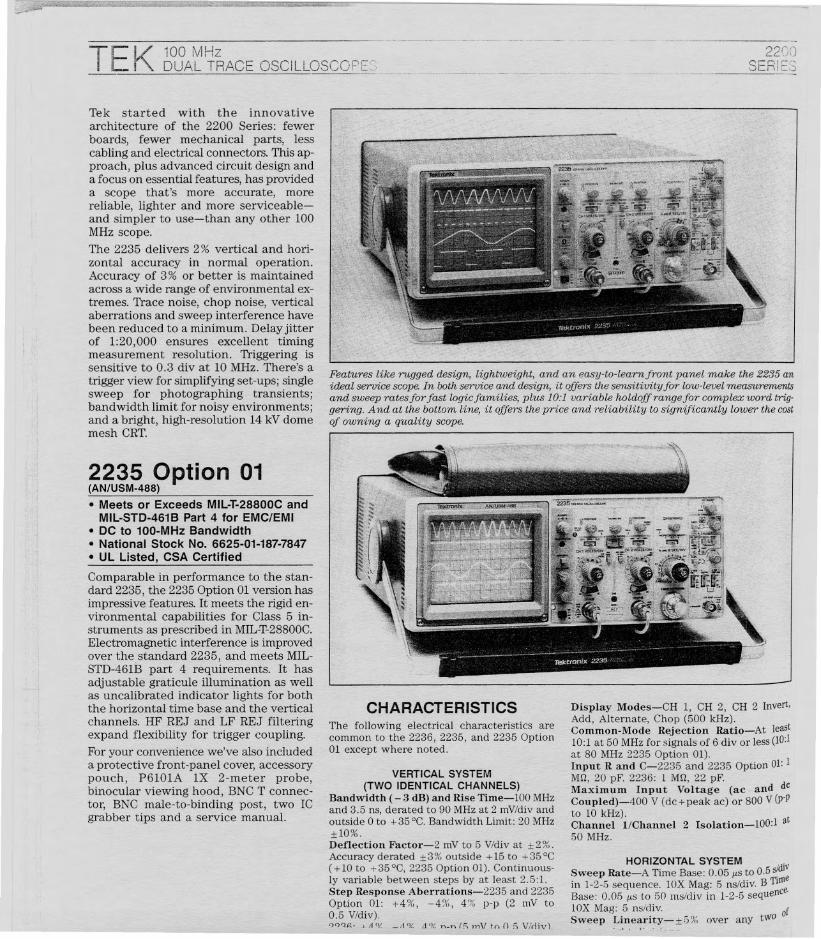
2235 Option 01(AN/USM-488)
• Meets or Exceeds MIL-T-28800C andMIL-STD-4618 Part 4 for EMC/EMI
• DC to 100-MHz Bandwidth• National Stock No. 6625-01-187-7847• UL Listed, CSA Certified
Comparable in performance to the standard 2235, the 2235 Option 01version hasimpressive features. It meets the rigid environmental capabilities for Class 5 instruments as prescribed in MIL-T-28800C.Electromagnetic interference is improvedover the standard 2235, and meets MILSTD-461B part 4 requirements. It hasadjustable graticule illumination as wellas uncalibrated indicator lights for boththe horizontal time base and the verticalchannels. HF REJ and LF REJ filteringexpand flexibility for trigger coupling.For your convenience we've also includeda protective front-panel cover, accessorypouch, P6101A IX 2-meter probe,binocular viewing hood, BNC T connector, BNC male-to-binding post, two ICgrabber tips and a service manual.
CHARACTERISTICSThe following electrical characteristics arecommon to the 2236, 2235, and 2235 Option01 except where noted.
VERTICAL SYSTEM
(TWO IDENTICAL CHANNELS)Bandwidth (- 3 dB) and Rise Time-lOO MHzand 3.5 ns, derated to 90 MHz at 2 mV/div andoutside 0 to + 35°C. Bandwidth Limit: 20 MHz±1O%.Deflection Factor-2 mV to 5 V/div at ±2%.Accuracy derated ±3% outside +15 to +35°C( + 10 to + 35°C, 2235 Option 01). Continuously variable between steps by at least 2.5:1.Step Response Aberrations-2235 and 2235Option 01: +4%, -4%, 4% Pop (2 mV to0.5 V/div).'-)')t}~. J. Ii IV _11 tv.: .:ily'. n_n r[; I"nVto () f; Vkliv).
Display Modes-CH I, CH 2, CH 2 Invert,Add, Alternate, Chop (500 kHz).Common-Mode Rejection Ratio-At least10:1 at 50 MHz for signals of 6 div or less (10:1at 80 MHz 2235 Option 01).Input Rand C-2235 and 2235 Option 01: IM£], 20 pF. 2236: 1 M£], 22 pF.Maximum Input Voltage (ac and deCoupled)-400 V (dc+peak ac) or 800 V (p-p
to 10 kHz). tChannel l/Channel 2 Isolation-lOO:l a50 MHz.
HORIZONTAL SYSTEM . ,Sweep Rate-A Time Base: 0.05 p's to 0.5 sldi\
in 1-2-5 sequence. lOX Mag: 5 ns/div. B TuneBase: O.Ofip.Sto fiO I11sidivin 1-2-5 sequence.lOX Mag: 5 ns/div. ISweep Linearity-±6~(, over any tWO 0

100 MHzDUAL TRACE OSCii_LOSCOPE·S
1.5 div
1.5 div
2.0 div
X-YOPERATIONDeflection Factors-Same as vertical system(V/div switch in calibrated detent).
Accuracy
Bandwidth-Y-Axis: same as scope's verticalsystem. X-Axis: 2.5 MHz.Phase Difference Between X-Axis and YAxis Amplifiers- ± 3 ° from dc to 150 kHzwith dc coupled inputs.
Dimensions mmin.mmin.
Width"
32812.932812.9Height'3
1375.41375.4Depth'2
44017.344017.3
Weight ""
kgIbkgIb
Net
6.113.57.316.2
*I Without handle. *2 Without front cover.*3 2235 Option 01 height with pouch is150 mm (5.9 in.).
CHARACTERISTICS
PHYSICAL CHARACTERISTICS
2235 & 2235Opt 01 2236
Shock-Operating: 30 g's, 1/2 sine, H-ms duration, 3 shocks per axis along each major axis.Total of 18 shocks.EMC-Meets Class B requirements per VDE0871B for radiated and conducted emission.2235 Option 01 AN/USM 488 Only: Meets requirements of MIL-STD-461B Part 4, CE03,CSOl, CS02, CS06, RE02 (to 1 GHz), and RS03(1 V/meter to 1 GHz).
The following characteristics are unique to the2236.Time Base Accuracy-Standard: 10 ppm(0.001%). With Option 14 TCXO: 0.5 ppm(0.00005%).Frequency-Range: sO.2 Hz to :2:100 MHz.Maximum Resolution: 0.00001 Hz. MaximumAccuracy: Equal to time base accuracy. Can begated!I*2Period-Range: :2:5 s to s10 ns. MaximumResolution: 10 ps. Maximum Accuracy: Equalto time base accuracy. Can be gated!I*"Width-Range: :2:5 s to s5 ns. MaximumResolution: 10 ps. Maximum Accuracy: Equalto time base accuracy ±10 ns. Can be gated! 1'2Delay Time-Range: :2:2.5 s to s500 ns. Maximum Resolution: 10 ps. Maximum Accuracy:Equal to time base accuracy ±20 ns!2.1.Time-Range: :2:2.5 s to sl ns. MaximumResolution: 10 ps. Maximum Accuracy: Equalto time base accuracy ±50 pS.*2Totalize-Over 8,000,000 events. Can begated.DC Volts-Range: 0 to 500 V. MaximumResolution: 100 j1.V. Accuracy: ±(U%. Input:Through side DMM leads""
X-Axis
±3%±4%
Y-Axis
±2%±3%
+15 to +35°Co to +50"C
POWER REQUIREMENTSLine Voltage Range-90 to 250 V ac. (No lineswitches or fuse changes needed.)Line Frequency-48 to 440 Hz.Maximum Power Consumption-2235: 40 W,70 VA. 2236: 60 W, 110 VA.DC Operation-12 to 30 V available with 1105,1106, and 1107.
OTHER CHARACTERISTICSProbe Adjust Signal-(2235/2236) Squarewave, 0.5 V ±5%, 1 kHz ±20%.Amplitude Calibrator-(2235 Option 01 only)Square wave, 0.5 V ±2%, 1 kHz ±20%.
100 mVldiv with ac and dc external, and 1 Vldivwith dc~lO external. Accuracy: ±20%. Delaydifference between trigger view (EXT input)and either vertical channel: <2.0 ns.External Trigger Input-Coupling: ac, dc, ordc ~ 10.Variable Holdoff Control-Increases A sweepholdoff time at least 10:1.
CRT AND DISPLAY FEATURESCRT-8xlO cm display; internal unilluminatedgraticule (2235 Option 01 is illuminated). Accelerating potential: 14 kV. GH (P31) phosphorstandard.Controls-Beam Finder, Focus, Separate Aand B Sweep Intensity, Trace Rotation. 2235Option 01 also has Variable Scale Illumination.Z-Axis Input-DC coupled, positive-goingsignal decreases intensity; 5 V p-p signal causesnoticeable modulation; de to 20 MHz.
ENVIRONMENTALAmbient Temperature-Operating: 0 to+50°C (except 2236 CTM ac RMSV, DCV, anda Modes: 0 to +40°C) Nonoperating: -55 to+ 75°C.Altitude-Operating: To 4600 m (15,000 ft).Maximum operating temperature decreased1° C/l,OOO ft (5,000 to 15,000 ft). Nonoperating: To 15 000 m (50,000 ft).Vibration-Operating: 15 minutes along eachof the major axes. 0.0l5-in. p-p displacement10 to 55 to 10 Hz in one minute cycles. Heldfor 10 minutes at 55 Hz (2.4 g's at 55 Hz).Humidity-Operating and Nonoperating: 95%,five cycles (120 hours) referenced to MILT-28800C, Paragraph 4.5.5.1.2.2.
1235& 2235
~01 0.35 div 1.0 div'236 04 div 12 div
i236 CTM 0'5 div 1'5 div
~5 divfor 2;35 Option' OJ..,150mV for 2235 Option 01.)V1'rigger Sensitivity-TV Field: 1.0 div of;I11Positesync. TV Line: 0.3 div (2235); 0.35;v (2236 and 2235 Option 01).andwidth Limiting (bandwidth limitIV'
'1.ltchdepressed)-20 MHz.Igh-Frequency Reject (2235 Option 0 IOIY)-Attenuates signals above 40 kHz.QIV Frequency Reject (2235 Option 01OIY)-Attenuates signals below 40 kHz.tigger System Operating Modes-Normal,,p automatic, TV line, TV field, and singleteep.
'igger View System-Same deflection fac~as vertical channels with internal sources;
Externalj 2235/2235-01
Internal(p-p volts)i 10 MHz
0.3 div"35 mV
I 60 MHz1.0 div120 mV
J~MHz
1.5 div"200 mV'2
12236 \10M Hz0.35 div
40 mVI 60 MHz
1.2div 150 mVI I~
1.5div 250 mV
12236CTM!-10MHz
0.5 div50 mV60 MHz
1.5 div160 mV
~MHz2.0 div300 mV
~igger (Internal Only) Sensitivity10 MHz 60 MHz 100 MHz
TRIGGERINGA Trigger Sensitivity
CALIBRATED SWEEP DELAYDelay Time Range-Continuously variablewith 10-turn control from < 0.5 +300 ns to> 10 div.Differential Delay Time Accuracy-(2235and 2235 Option 01) ± 1% (+ 15 to + 35°C);±2% (0 to +500C).~Time Measurement Accuracy-(2236) Maxaccuracy equal to time base accuracy ±50 ps.
i'TimeBase Accuracy With Standard Oscillator:10 ppm (0.001%); with Option 14 TCXO
\ (Temperature Compensated Crystal Oscillator):0.5 ppm (0.00005%).
I Delay Jitter-2236: 10,000:1 (0.01%). 2235,and 2235 Option 01: 20,000:1 (0.005%).
I
I Accuracy*1
I +15 to +35°C 0 to +50 °CUnmagnified ±2% ±3%
Magnified ±3% ±4%
d +10 to +35°Cfor 2235 Option OJ.Display Modes-A, Alternate (A Intensifiedand B Delayed) and B.

OPTIONSOption 02-(2235,2236 only) Frontpanel cover and accessory pouch.Option 14-(2236 only) TCXOTemperature-Compensated CrystalOscillator, 0.5 ppm accuracy.Option 33-Travel Line PackageIncludes rubber molding, accessorypouch, front panel cover, carryingstrap.(2235)(2236)(2220/2230) Includes rubbermolding, carrying strap.
CONVERSION KITSRackmount Adapter-Includes: Rackmount depth extenders, allmounting hardware, labels, instruction manual.(2335) Order 016-0466-00 $130(2235 Option 01) Order 016-0833-00 5145(2236) Order 016-0015-00 $2!)()TCXO Retrofit Kit-(2236 only)Temperature compensated crystaloscillator, 0.5 ppm accuracy.Order 040-1136-00 $370
INTERNATIONAL POWER PLUG OPTIONSOption AI-Universal Euro 220 V, 50 Hz.Order 020-0859-00. 82HOption A2-UK 240 V, 50 Hz.Order 020-0860-00.Option A3-Australian 240 V, 50 Hz.Order 020-0861-00. $27Option A4-North American 240 V, 60 Hz.Order 020-0862-00. 830Option A5-Switzerland 220 V, 50 Hz.Order 020-0863-00. 819
WARRANTY-PLUS SERVICE PLANSSee Customer Service Section
Ml-(2235/2235 Option 01)2 Calibrations.Ml-(2236) 2 Calibrations.M2-(2235/2235 Option 01) +2 YearsService.M2-(2236) + 2 Years Service.M3-(2235/2235 Option 01) 2 YearsService & 4 Calibrations.M3-(2236) 2 Years Service &4 Calibrations.M4-(2235/2235 Option 01)5 Calibrations.M4-(2236) 5 Calibrations.M5-(2235/2235 Option 01)9 Calibrations + 2 Years Service.M5-(2236) 9 Calibrations+ 2 Years Service.
826828
Option 01
RECOMMENDED CARTK212-For on-site mobility. SeeAccessories Section. 8350
SERVICE MANUALS(2235) Order 070-4206-00(2236) Order 070-4204-00*1 Standard with the 2235
(AN/USM-488).*2 Recommend use with front panel cover
(200-2520-00).
81458290
8130
8680
81.9583.80
H7.50
S1.140
81,580
82.090
81.885
Carrying Strap-Order 34G-0199-00Carrying Case*2-Order 016-0792-01Rackmount Adaptor Kits(2235) Order 016-0466-00(2235 Option 01)Order 016-0833-00(2236) Order 016-0015-00CRT Light Filter-(Clear* 1) Order 337-2775-01(Blue) Order 337-2775-001107 Mounting KitOrder 016-0785-001107 DC Inverter-See end of thisSection1106 Battery Pack-See end of thisSection1105 Power Supply-See end ofthis SectionA6901 Ground IsolationMonitor-See Accessories Section.A6902B Voltage Isolator-See Accessories Section.
RECOMMENDED PROBES
See Probe Section for additional probes.P6121-lOX Probe. 8100P6122-lOX Probe. 858P6420-DMM RF. 815540 kV DMM-Order 010-0277-00 8180P6602 Temperature Probe-Foruse with 2236 CTM. 8235
RECOMMENDED CAMERASC-5C-See Accessories Section.(2235 Option 01) C-5C Option 02 8465(2235, 2236) C-5C Option 04 8495C-7-See Accessories Section.(2235, 2236) C-7 Option 02 8595(2235 Option 01) Option 03 8565C-4-(2235 Option 01) See Acces-sories Section. 8375
8:37
c- S5H
+ S2HG
+ S200
'050
86.50
+ 8135+ 51()0
+ 8125+ 8150
+ 8380
+ 8385+ 8425
+ 8450
+ S !JOO
+ 8805
814.258198(W
OPTIONAL ACCESSORIES
Front Panel Cover and AccessoryPouch*1 -Order 020-0672-02Front Panel Cover*1 -Order 200-2520-00Accessory POUCh*l-Order 016-0677-02Viewing Hoods-(Collapsible) Order 016-0592-00(Binocular) Order 016-0566-00*1(Polarized) Order 016-0180-00
RMS AC Volts-AC Coupled: True RMS with20 Hz to 20 kHz frequency range. Range: 0 to350 V. Maximum Resolution: 100 JJ- V. Accuracy:±1.0%. Input: Through side DMM leads.*2CH 1 Volts-Measures average dc voltage(with CH 1 dc coupling) or true RMS voltage(with CH 1 ac coupling); lX/lOX ranged bycoded probes: Single Sweep button zerosdisplay and permits relative dc and ac RMSmeasurements. Range, dc and ac Volts: 0 to50 V (500 V dc/350 V ac with P6121 lOXProbe). Maximum Resolution, dc and ac Volts:100 ~tV (1 mV with P6121). Maximum Accuracy,dc Volts (18 to 28°C): ± 0.3 % with IX probe,±0.5% with lOX probe. Maximum Accuracy,ac Volts with IX probe (18 to 28°C): ±2%, 50to 100 Hz, ±1%, 100 Hz to 20 kHz. MaximumAccuracy, ac Volts with lOX Probe: ±2%, 20 Hzto 20 kHz, with proper probe compensation.*2Resistance-Range: 0 0 to 1.99 GO. MaximumResolution: 0.01 0. Accuracy: To 0.15%.Automatic diode detection displays forwardvoltage drop to ± 1%; continuity mode activates tone if resistance is <5 0.* 2
Temperature-Uses Optional Thktronix P6602Temperature Probe. Temperatures in C or Fselected with Freq/t.Time button. Range: -62to +230°C (-80 to +446 OF). Resolution: To0.1 ° (either range). Accuracy: To ±2% ofreading ±1.5°C; ±2% of reading ±2.70°F.Multimeter Inputs-Isolated from oscilloscope ground. Input Z: 10 MO. Maximum Input Voltage: 500 V (dc+peak ac), for allfunctions.
*1 Ranges, resolutions, and accuracies can bedegraded due to gating errors and a smallernumber of automatic averages made during a gated frequency, period, or widthmeasurement. For complete formulaspecifications see operator's manual.
*2 For complete accuracy and resolution errorformula specifications see operator'smanual.
ORDERING INFORMATION2236 Oscilloscope With Counter/Timer/Multimeter 82,795Includes: Two P612110X voltage probes; DMMleads; Reference Guide; Operator Manual(070-4205-00).2235 Oscilloscope $1,575Includes: Two P6122 lOX voltage probes;Operator manual (070-4207-00).2235 Option 01 Oscilloscope(AN/USM-488) Order 2235L 82.195Includes: Two P6122 lOX Voltage Probes(015-0467 -00); P6101A IX Voltage Probe(010-6101-03); viewing hood (016-0566-00);BNC T-connector (103-0030-00); BNC male tobinding post (103-0033-00); front panel cover(200-2520-00); accessory pouch (016-0677-02);two grabber tips (013-0191-00); OperatorManual (070-4976-00); Service Manual(070-4977-00).
324 To order, calf ~Iour local Tektronix Sales Office, or cal! lek's National Marl~eting Center,Tali free: 1-800-426-2200, Ext. 99. in Oregon eaB coHeet: (503) 627-9000, Ext. 99.