220 LR W S 1 - kawneer.com · 220 LR W S ADMD140EN NOVEMBER, 2018 DEADLOAD CHARTS Horizontal or...
24
Laws and building and safety codes governing the design and use of glazed entrance, window, and curtain wall products vary widely. Kawneer does not control the selection of product configurations, operating hardware, or glazing materials, and assumes no responsibility therefor. Kawneer reserves the right to change configuration without prior notice when deemed necessary for product improvement. © Kawneer Company, Inc., 2013 kawneer.com 1 EC 97911-182 2250 L-R Wall System ADMD140EN NOVEMBER, 2018 FEATURES For specific product applications, Consult your Kawneer representative. Features • Economical • 2-1/4" sight line • 1" infill system has 5" or 7-1/4" depth members • 1/4" infill system has 4-1/4" or 6-1/2" depth members • Outside glazed • SSG option for vertical mullions • Thermal break via polymer glazing clip • Permanodic TM anodized finishes in seven choices • Painted finishes in standard and custom choices Optional Features • Two color capability • Project specific U-factors (See Thermal Charts) Product Applications • Low-rise curtain wall applications of four stories or less • Punched opening or ribbon window applications • Integrated entrance framing allowing Kawneer entrances or other specialty • entrances to be included • Integrates with GLASSvent TM windows for curtain wall
Transcript of 220 LR W S 1 - kawneer.com · 220 LR W S ADMD140EN NOVEMBER, 2018 DEADLOAD CHARTS Horizontal or...

Law
s an
d bu
ildin
g an
d sa
fety
cod
es g
over
ning
the
desi
gn a
nd u
se o
f gla
zed
entra
nce,
win
dow
, and
cur
tain
wal
l pro
duct
s va
ry w
idel
y. K
awne
er d
oes
not c
ontro
l th
e se
lect
ion
of p
rodu
ct c
onfig
urat
ions
, ope
ratin
g ha
rdw
are,
or g
lazi
ng m
ater
ials
, an
d as
sum
es n
o re
spon
sibi
lity
ther
efor
.
Kaw
neer
rese
rves
the
right
to c
hang
e co
nfigu
ratio
n w
ithou
t prio
r not
ice
whe
n de
emed
nece
ssar
y fo
r pro
duct
impr
ovem
ent.
© K
awne
er C
ompa
ny, I
nc.,
2013
kawneer.com
1
EC 97911-182
2250 L-R Wall System
ADMD140EN
NOVEMBER, 2018FEATURES
For specific product applications,Consult your Kawneer representative.
Features• Economical• 2-1/4" sight line• 1" infill system has 5" or 7-1/4" depth members• 1/4" infill system has 4-1/4" or 6-1/2" depth members• Outside glazed• SSG option for vertical mullions• Thermal break via polymer glazing clip• PermanodicTM anodized finishes in seven choices• Painted finishes in standard and custom choices
Optional Features• Two color capability• Project specific U-factors (See Thermal Charts)
Product Applications• Low-rise curtain wall applications of four stories or less• Punched opening or ribbon window applications• Integrated entrance framing allowing Kawneer entrances or other specialty• entrances to be included• Integrates with GLASSventTM windows for curtain wall

Law
s an
d bu
ildin
g an
d sa
fety
cod
es g
over
ning
the
desi
gn a
nd u
se o
f gla
zed
entra
nce,
win
dow
, and
cur
tain
wal
l pro
duct
s va
ry w
idel
y. K
awne
er d
oes
not c
ontro
l th
e se
lect
ion
of p
rodu
ct c
onfig
urat
ions
, ope
ratin
g ha
rdw
are,
or g
lazi
ng m
ater
ials
, an
d as
sum
es n
o re
spon
sibi
lity
ther
efor
.
Kaw
neer
rese
rves
the
right
to c
hang
e co
nfigu
ratio
n w
ithou
t prio
r not
ice
whe
n de
emed
nece
ssar
y fo
r pro
duct
impr
ovem
ent.
© K
awne
er C
ompa
ny, I
nc.,
2013
kawneer.com
2
EC 97911-182
2250 L-R Wall System
ADMD140EN
NOVEMBER, 2018BLANK PAGE

Law
s an
d bu
ildin
g an
d sa
fety
cod
es g
over
ning
the
desi
gn a
nd u
se o
f gla
zed
entra
nce,
win
dow
, and
cur
tain
wal
l pro
duct
s va
ry w
idel
y. K
awne
er d
oes
not c
ontro
l th
e se
lect
ion
of p
rodu
ct c
onfig
urat
ions
, ope
ratin
g ha
rdw
are,
or g
lazi
ng m
ater
ials
, an
d as
sum
es n
o re
spon
sibi
lity
ther
efor
.
Kaw
neer
rese
rves
the
right
to c
hang
e co
nfigu
ratio
n w
ithou
t prio
r not
ice
whe
n de
emed
nece
ssar
y fo
r pro
duct
impr
ovem
ent.
© K
awne
er C
ompa
ny, I
nc.,
2013
kawneer.com
3
EC 97911-182
2250 L-R Wall System
ADMD140EN
NOVEMBER, 2018INDEX
PICTORIAL VIEW .................................................................................... 51/4 SIZE DETAILS (1" SYSTEM) ........................................................ 6, 71/4 SIZE DETAILS (1/4" SYSTEM) ..................................................... 8, 9ANCHORING ......................................................................................... 10WIND LOAD CHARTS ...................................................................... 11-14DEADLOAD CHARTS ...................................................................... 15-16THERMAL CHARTS ......................................................................... 17-24
Architects – Most extrusion and window types illustrated in this catalog are standard products for Kawneer. These concepts have been expanded and modified to afford you design freedom. Some miscellaneous details are non-standard and are intended to demonstrate how the system can be modified to expand design flexibility. Please contact your Kawneer representative for further assistance.
LAWS AND BUILDING AND SAFETY CODES GOVERNING THE DESIGN AND USE OF GLAZED ENTRANCE, WINDOW, AND CURTAIN WALL PRODUCTS VARY WIDELY. KAWNEER DOES NOT CONTROL THE SELECTION OF PRODUCT CONFIGURATIONS, OPERATING HARDWARE, OR GLAZING MATERIALS, AND ASSUMES NO RESPONSIBILITY THEREFOR.
Metric (SI) conversion figures are included throughout these details for reference. Numbers in parentheses ( ) are millimeters unless otherwise noted.
The following metric (SI ) units are found in these details: m – meter cm – centimeter mm – millimeter s – second Pa – pascal MPa – megapascal

Law
s an
d bu
ildin
g an
d sa
fety
cod
es g
over
ning
the
desi
gn a
nd u
se o
f gla
zed
entra
nce,
win
dow
, and
cur
tain
wal
l pro
duct
s va
ry w
idel
y. K
awne
er d
oes
not c
ontro
l th
e se
lect
ion
of p
rodu
ct c
onfig
urat
ions
, ope
ratin
g ha
rdw
are,
or g
lazi
ng m
ater
ials
, an
d as
sum
es n
o re
spon
sibi
lity
ther
efor
.
Kaw
neer
rese
rves
the
right
to c
hang
e co
nfigu
ratio
n w
ithou
t prio
r not
ice
whe
n de
emed
nece
ssar
y fo
r pro
duct
impr
ovem
ent.
© K
awne
er C
ompa
ny, I
nc.,
2013
kawneer.com
4
EC 97911-182
2250 L-R Wall System
ADMD140EN
NOVEMBER, 2018BLANK PAGE

Law
s an
d bu
ildin
g an
d sa
fety
cod
es g
over
ning
the
desi
gn a
nd u
se o
f gla
zed
entra
nce,
win
dow
, and
cur
tain
wal
l pro
duct
s va
ry w
idel
y. K
awne
er d
oes
not c
ontro
l th
e se
lect
ion
of p
rodu
ct c
onfig
urat
ions
, ope
ratin
g ha
rdw
are,
or g
lazi
ng m
ater
ials
, an
d as
sum
es n
o re
spon
sibi
lity
ther
efor
.
Kaw
neer
rese
rves
the
right
to c
hang
e co
nfigu
ratio
n w
ithou
t prio
r not
ice
whe
n de
emed
nece
ssar
y fo
r pro
duct
impr
ovem
ent.
© K
awne
er C
ompa
ny, I
nc.,
2013
kawneer.com
5
EC 97911-182
2250 L-R Wall System
ADMD140EN
NOVEMBER, 2018PICTORIAL VIEW

Law
s an
d bu
ildin
g an
d sa
fety
cod
es g
over
ning
the
desi
gn a
nd u
se o
f gla
zed
entra
nce,
win
dow
, and
cur
tain
wal
l pro
duct
s va
ry w
idel
y. K
awne
er d
oes
not c
ontro
l th
e se
lect
ion
of p
rodu
ct c
onfig
urat
ions
, ope
ratin
g ha
rdw
are,
or g
lazi
ng m
ater
ials
, an
d as
sum
es n
o re
spon
sibi
lity
ther
efor
.
Kaw
neer
rese
rves
the
right
to c
hang
e co
nfigu
ratio
n w
ithou
t prio
r not
ice
whe
n de
emed
nece
ssar
y fo
r pro
duct
impr
ovem
ent.
© K
awne
er C
ompa
ny, I
nc.,
2013
kawneer.com
6
EC 97911-182
1010A
87
1111A
7A
9
6
3
2
4
5
141516
1213
1717A
18A18
1
5"(127)
7-1/4"(184.2)
2-1/
4"(5
7.2)
5"(1
27)
2-1/4"(57.2)
7-1/
4"(1
84.2
)
5"(1
27)
7-1/
4"(1
84.2
)
6-1/
4"(1
58.8
)6-
1/4"
(158
.8)
2250 L-R Wall System
ADMD140EN
NOVEMBER, 20181/4 SIZE DETAILS (1" SYSTEM)
ELEVATION IS NUMBER KEYED TO DETAILS
1
3
2
4
5
6
9
7
10
7A
10A
8
11 11A
SSG MULLIONS
SSG MULLION
Additional information and CAD details are available at www.kawneer.com
* INSTALLER NOTE: Installer is responsible for all required compatibility review and approvals with the Structural Silicone Manufacturer and the Insulated Glass Unit Manufacturers.
Structural Silicone Sealant (by Others)*
Law
s an
d bu
ildin
g an
d sa
fety
cod
es g
over
ning
the
desi
gn a
nd u
se o
f gla
zed
entra
nce,
win
dow
, and
cur
tain
wal
l pro
duct
s va
ry w
idel
y. K
awne
er d
oes
not c
ontro
l th
e se
lect
ion
of p
rodu
ct c
onfig
urat
ions
, ope
ratin
g ha
rdw
are,
or g
lazi
ng m
ater
ials
, an
d as
sum
es n
o re
spon
sibi
lity
ther
efor
.
Kaw
neer
rese
rves
the
right
to c
hang
e co
nfigu
ratio
n w
ithou
t prio
r not
ice
whe
n de
emed
nece
ssar
y fo
r pro
duct
impr
ovem
ent.
© K
awne
er C
ompa
ny, I
nc.,
2013
kawneer.com
7
EC 97911-182
2-1/
4"(5
7.2)
4-1/2"(114.3)
7-1/
4"(1
84.2
)5"
(127
)
7-9/
16"
(192
.1)
9-13
/16"
(249
.2)
2-1/4"(57.2)
7/8"(22.2)
2-1/
4"(5
7.2)
4-1/2"(114.3)
2-1/
4"(5
7.2)
4-1/2"(114.3)
2250 L-R Wall System
ADMD140EN
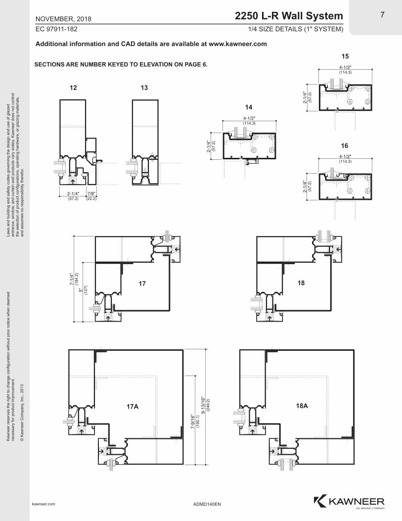
NOVEMBER, 20181/4 SIZE DETAILS (1" SYSTEM)
SECTIONS ARE NUMBER KEYED TO ELEVATION ON PAGE 6.
17
17A
18
18A
12
14
15
16
13
Additional information and CAD details are available at www.kawneer.com

Law
s an
d bu
ildin
g an
d sa
fety
cod
es g
over
ning
the
desi
gn a
nd u
se o
f gla
zed
entra
nce,
win
dow
, and
cur
tain
wal
l pro
duct
s va
ry w
idel
y. K
awne
er d
oes
not c
ontro
l th
e se
lect
ion
of p
rodu
ct c
onfig
urat
ions
, ope
ratin
g ha
rdw
are,
or g
lazi
ng m
ater
ials
, an
d as
sum
es n
o re
spon
sibi
lity
ther
efor
.
Kaw
neer
rese
rves
the
right
to c
hang
e co
nfigu
ratio
n w
ithou
t prio
r not
ice
whe
n de
emed
nece
ssar
y fo
r pro
duct
impr
ovem
ent.
© K
awne
er C
ompa
ny, I
nc.,
2013
kawneer.com
8
EC 97911-182
66A
77A5
3
2
4
4
8 9
10 11A11
1
4-1/4"(108)
2-1/
4"(5
7.2)
6-1/2"(165.1)
5-1/
2"(1
39.7
)
2-1/4"(57.2)
4-1/
4"(1
08)
6-1/
2"(1
65.1
)
2250 L-R Wall System
ADMD140EN
NOVEMBER, 20181/4 SIZE DETAILS (1/4" SYSTEM)
ELEVATION IS NUMBER KEYED TO DETAILS
1
3
2
4
5 6 76A 7A
SSG MULLIONS
Additional information and CAD details are available at www.kawneer.com
* INSTALLER NOTE: Installer is responsible for all required compatibility review and approvals with the Structural Silicone Manufacturer and the Insulated Glass Unit Manufacturers.
Structural Silicone Sealant (by Others)*
Law
s an
d bu
ildin
g an
d sa
fety
cod
es g
over
ning
the
desi
gn a
nd u
se o
f gla
zed
entra
nce,
win
dow
, and
cur
tain
wal
l pro
duct
s va
ry w
idel
y. K
awne
er d
oes
not c
ontro
l th
e se
lect
ion
of p
rodu
ct c
onfig
urat
ions
, ope
ratin
g ha
rdw
are,
or g
lazi
ng m
ater
ials
, an
d as
sum
es n
o re
spon
sibi
lity
ther
efor
.
Kaw
neer
rese
rves
the
right
to c
hang
e co
nfigu
ratio
n w
ithou
t prio
r not
ice
whe
n de
emed
nece
ssar
y fo
r pro
duct
impr
ovem
ent.
© K
awne
er C
ompa
ny, I
nc.,
2013
kawneer.com
9
EC 97911-182
2-1/
4"(5
7.2)
4"(101.6)
2-1/
4"(5
7.2)
4"(101.6)
2-1/4"(57.2)
7/8"(22.2)
4-1/
4"(1
08)
6-1/
2"(1
65.1
)
9-1/
16"
(230
.2)
6-25
/32"
(172
.2)
2250 L-R Wall System
ADMD140EN
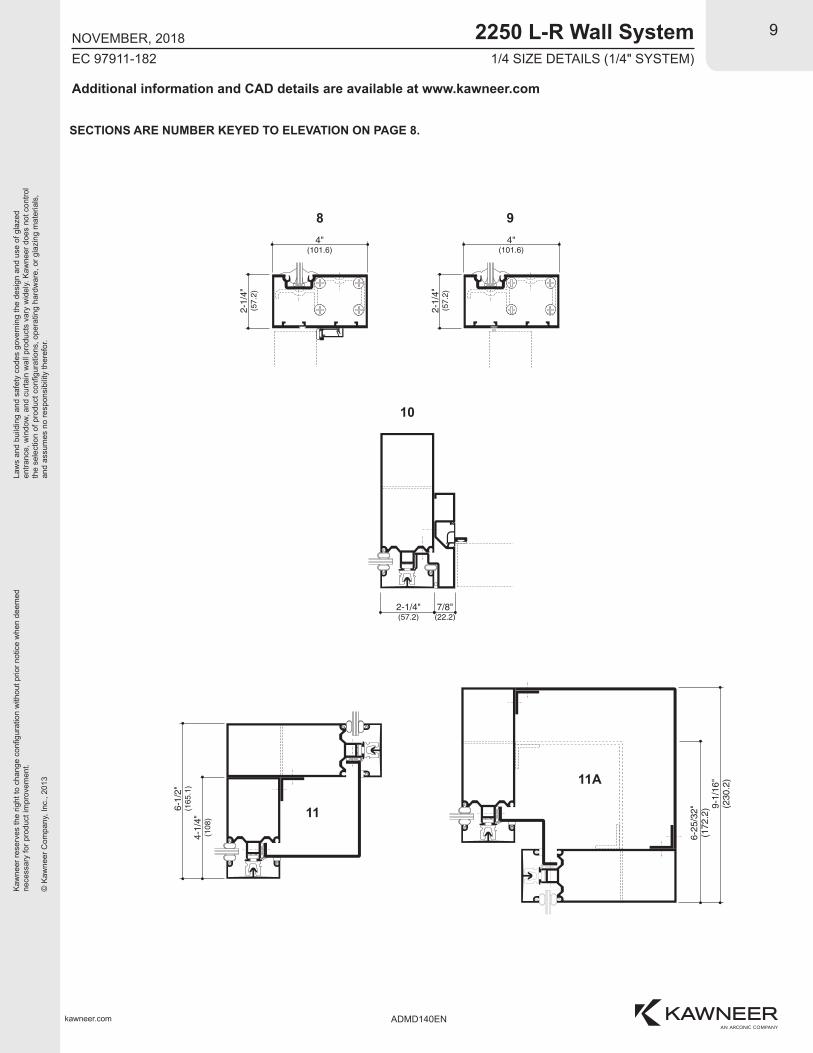
NOVEMBER, 20181/4 SIZE DETAILS (1/4" SYSTEM)
SECTIONS ARE NUMBER KEYED TO ELEVATION ON PAGE 8.
11
11A
10
8 9
Additional information and CAD details are available at www.kawneer.com

Law
s an
d bu
ildin
g an
d sa
fety
cod
es g
over
ning
the
desi
gn a
nd u
se o
f gla
zed
entra
nce,
win
dow
, and
cur
tain
wal
l pro
duct
s va
ry w
idel
y. K
awne
er d
oes
not c
ontro
l th
e se
lect
ion
of p
rodu
ct c
onfig
urat
ions
, ope
ratin
g ha
rdw
are,
or g
lazi
ng m
ater
ials
, an
d as
sum
es n
o re
spon
sibi
lity
ther
efor
.
Kaw
neer
rese
rves
the
right
to c
hang
e co
nfigu
ratio
n w
ithou
t prio
r not
ice
whe
n de
emed
nece
ssar
y fo
r pro
duct
impr
ovem
ent.
© K
awne
er C
ompa
ny, I
nc.,
2013
kawneer.com
10
EC 97911-182
2250 L-R Wall System
ADMD140EN
NOVEMBER, 2018ANCHORING
Law
s an
d bu
ildin
g an
d sa
fety
cod
es g
over
ning
the
desi
gn a
nd u
se o
f gla
zed
entra
nce,
win
dow
, and
cur
tain
wal
l pro
duct
s va
ry w
idel
y. K
awne
er d
oes
not c
ontro
l th
e se
lect
ion
of p
rodu
ct c
onfig
urat
ions
, ope
ratin
g ha
rdw
are,
or g
lazi
ng m
ater
ials
, an
d as
sum
es n
o re
spon
sibi
lity
ther
efor
.
Kaw
neer
rese
rves
the
right
to c
hang
e co
nfigu
ratio
n w
ithou
t prio
r not
ice
whe
n de
emed
nece
ssar
y fo
r pro
duct
impr
ovem
ent.
© K
awne
er C
ompa
ny, I
nc.,
2013
kawneer.com
11
EC 97911-182
2250 L-R Wall System
ADMD140EN
NOVEMBER, 2018
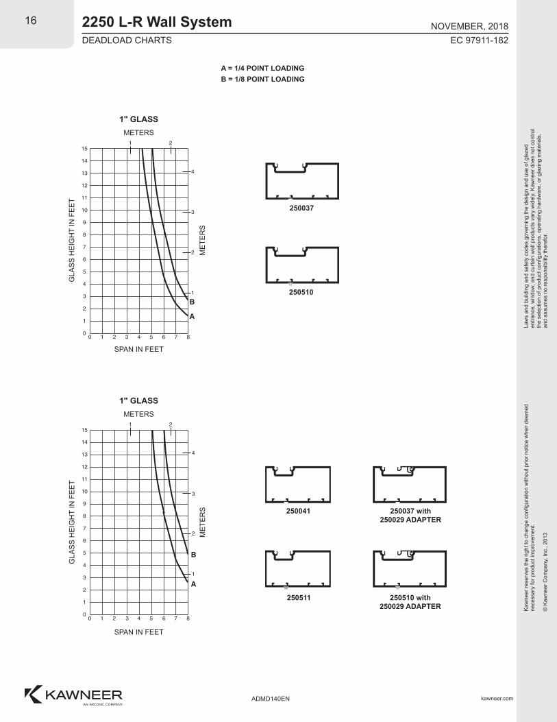
DEADLOAD CHARTSHorizontal or deadload limitations are based upon 1/8" (3.2) maximum deflection at the center of an intermediate horizontal member. The accompanying charts are calculated for 1/4" (6.4) and 1" (25.4) thick glass supported on two setting blocks placed at the loading points shown.
WIND LOAD CHARTSMullions are designed for deflection limitations in accordance with AAMA TIR-A11 of L/175 up to 13'-6" and L/240 +1/4" above 13'-6". These curves are for mullions WITH HORIZONTALS and are based on engineering calculations for stress and deflection. Allowable wind load stress for ALUMINUM 15,152 psi (104 MPa), STEEL 30,000 psi (207 MPa). Charted curves, in all cases are for the limiting value. Wind load charts contained herein are based upon nominal wind load utilized in allowable stress design. A conversion from Load Resistance Factor Design (LRFD) is provided. To convert ultimate wind loads to nominal loads, multiply ultimate wind loads by a factor of 0.6 per ASCE/SEI 7. A 4/3 increase in allowable stress has not been used to develop these curves. For special situations not covered by these curves, contact your Kawneer representative for additional information.
WIND LOAD / DEAD LOAD CHARTS

Law
s an
d bu
ildin
g an
d sa
fety
cod
es g
over
ning
the
desi
gn a
nd u
se o
f gla
zed
entra
nce,
win
dow
, and
cur
tain
wal
l pro
duct
s va
ry w
idel
y. K
awne
er d
oes
not c
ontro
l th
e se
lect
ion
of p
rodu
ct c
onfig
urat
ions
, ope
ratin
g ha
rdw
are,
or g
lazi
ng m
ater
ials
, an
d as
sum
es n
o re
spon
sibi
lity
ther
efor
.
Kaw
neer
rese
rves
the
right
to c
hang
e co
nfigu
ratio
n w
ithou
t prio
r not
ice
whe
n de
emed
nece
ssar
y fo
r pro
duct
impr
ovem
ent.
© K
awne
er C
ompa
ny, I
nc.,
2013
kawneer.com
12
EC 97911-182
9
06
7
8
1 2 3
10
11
12
13
14
15
17
16
18
E
D
C
4 5 76 8
2
3
4
5
19
20
21
B
A 1 2
6
162302
162302
12
09
10
11
1 2 3
13
14
15
16
17
18
20
19
21
E4 5 7
3
4
5
6
22
23
24
D
A
C
B
1 2
7
6 8
9
06
7
8
1 2 3
10
11
12
13
14
15
17
16
18
E
D
C
4 5 76 8
2
3
4
5
19
20
21
B
A
1 2
6
12
09
10
11
1 2 3
13
14
15
16
17
18
20
19
21
E4 5 76 8
3
4
5
6
22
23
24
D
C
B
A
1 2
7
2250 L-R Wall System
ADMD140EN
NOVEMBER, 2018SINGLE SPAN WIND LOAD CHARTS
250001
250004
METERS
MULLION CENTERS IN FEET
MU
LLIO
N H
EIG
HT
IN F
EE
T
ME
TER
S
METERS
MULLION CENTERS IN FEET
MU
LLIO
N H
EIG
HT
IN F
EE
T
ME
TER
S
I = 7.471 (310.9 x 10⁴)S = 2.287 (37.4 x 10³)
I = 4.5071(87.60 x 10⁴)S = 1.968(32.25 x 10³)
162302 SteelI = 2.111 (87.9 x 10⁴)S = 1.108 (18.2 x 10³)
162302 SteelI = 2.111 (87.9 x 10⁴)S = 1.108 (18.2 x 10³)
250001 Mullionwith 162302 Steel
METERS
MULLION CENTERS IN FEETM
ULL
ION
HE
IGH
T IN
FE
ET
ME
TER
S
250004 Mullion
METERS
MULLION CENTERS IN FEET
MU
LLIO
N H
EIG
HT
IN F
EE
T
ME
TER
S
250004 Mullionwith 162302 Steel
250001 Mullion
WITH HORIZONTALSWITH HORIZONTALS
WITH HORIZONTALSWITH HORIZONTALS
Allowable Stress Design Load
LRFD Ultimate Design Load
A = 20 PSF (960) 33 PSF (1580)B = 30 PSF (1440) 50 PSF (2400)C = 40 PSF (1920) 67 PSF (3200)D = 50 PSF (2400) 83 PSF (4000)E = 60 PSF (2880) 100 PSF (4790)

Law
s an
d bu
ildin
g an
d sa
fety
cod
es g
over
ning
the
desi
gn a
nd u
se o
f gla
zed
entra
nce,
win
dow
, and
cur
tain
wal
l pro
duct
s va
ry w
idel
y. K
awne
er d
oes
not c
ontro
l th
e se
lect
ion
of p
rodu
ct c
onfig
urat
ions
, ope
ratin
g ha
rdw
are,
or g
lazi
ng m
ater
ials
, an
d as
sum
es n
o re
spon
sibi
lity
ther
efor
.
Kaw
neer
rese
rves
the
right
to c
hang
e co
nfigu
ratio
n w
ithou
t prio
r not
ice
whe
n de
emed
nece
ssar
y fo
r pro
duct
impr
ovem
ent.
© K
awne
er C
ompa
ny, I
nc.,
2013
kawneer.com
13
EC 97911-182
162302
8
05
6
7
1 2 3
9
10
11
12
13
14
16
15
17
E
D
C
B
4 5 76 8
2
3
4
5
18
19
20
A
1 2
6
12
09
10
11
1 2 3 4
13
14
15
16
DE
17
18
20
19
21
5 76 8
3
4
5
6
C
22
23
24
B A
1 2
7
7
04
5
6
1 2 3
8
9
10
11
E
D12
13
15
14
16
C
B
A
4 5 76 8
2
3
4
17
18
191 2
5
7
04
5
6
1 2 3
8
9
10
11
E
D12
13
15
14
16
C
B
A
4 5 76 8
2
3
4
17
18
191 2
5
2250 L-R Wall System
ADMD140EN
NOVEMBER, 2018SINGLE SPAN WIND LOAD CHARTS
250009
250011
METERS
MULLION CENTERS IN FEET
MU
LLIO
N H
EIG
HT
IN F
EE
T
ME
TER
S
METERS
MULLION CENTERS IN FEET
MU
LLIO
N H
EIG
HT
IN F
EE
T
ME
TER
S
I = 5.310 (221.0 x 10⁴)S = 2.044 (33.5 x 10³)
I = 2.271 (94.5 x 10⁴)S = 1.007 (16.5 x 10³)
162302 SteelI = 2.111 (87.9 x 10⁴)S = 1.108 (18.2 x 10³)
250009 Mullionwith 162302 Steel
METERS
MULLION CENTERS IN FEET
MU
LLIO
N H
EIG
HT
IN F
EE
T
ME
TER
S
METERS
MULLION CENTERS IN FEET
MU
LLIO
N H
EIG
HT
IN F
EE
T
ME
TER
S
250009 Mullion
WITH HORIZONTALS WITHOUT HORIZONTALS
WITH HORIZONTALSWITH HORIZONTALS
Allowable Stress Design Load
LRFD Ultimate Design Load
A = 20 PSF (960) 33 PSF (1580)B = 30 PSF (1440) 50 PSF (2400)C = 40 PSF (1920) 67 PSF (3200)D = 50 PSF (2400) 83 PSF (4000)E = 60 PSF (2880) 100 PSF (4790)

Law
s an
d bu
ildin
g an
d sa
fety
cod
es g
over
ning
the
desi
gn a
nd u
se o
f gla
zed
entra
nce,
win
dow
, and
cur
tain
wal
l pro
duct
s va
ry w
idel
y. K
awne
er d
oes
not c
ontro
l th
e se
lect
ion
of p
rodu
ct c
onfig
urat
ions
, ope
ratin
g ha
rdw
are,
or g
lazi
ng m
ater
ials
, an
d as
sum
es n
o re
spon
sibi
lity
ther
efor
.
Kaw
neer
rese
rves
the
right
to c
hang
e co
nfigu
ratio
n w
ithou
t prio
r not
ice
whe
n de
emed
nece
ssar
y fo
r pro
duct
impr
ovem
ent.
© K
awne
er C
ompa
ny, I
nc.,
2013
kawneer.com
14
EC 97911-182
5
02
3
4
1 2 3
6
7
8
9E
10
11
13
12
14
D
C
B
A
4 5 76 8
1
2
3
4
15
16
171 2
5
5
02
3
4
1 2 3
6
7
8
9E
10
11
13
12
14
B
DC
A
4 5 76 8
1
2
3
4
15
16
171 2
5
5
02
3
4
1 2 3
6
7
8
9ED
10
11
13
12
14
B
C
A
4 5 76 8
1
2
3
4
15
16
171 2
5
5
02
3
4
1 2 3
6
7
8
9ED
10
11
13
12
14
C
B
A
4 5 76 8
1
2
3
4
15
16
171 2
5
2250 L-R Wall System
ADMD140EN
NOVEMBER, 2018SINGLE SPAN WIND LOAD CHARTS
250014
250019
METERS
MULLION CENTERS IN FEET
MU
LLIO
N H
EIG
HT
IN F
EE
T
ME
TER
S
METERS
MULLION CENTERS IN FEET
MU
LLIO
N H
EIG
HT
IN F
EE
T
ME
TER
S
I = 1.547 (64.3 x 10⁴)S = 0.872 (14.2 x 10³)
I = 1.266 (52.7 x 10⁴)S = 0.882 (14.5 x 10³)
WITHOUT HORIZONTALS
METERS
MULLION CENTERS IN FEETM
ULL
ION
HE
IGH
T IN
FE
ET
ME
TER
S
WITH HORIZONTALS
METERS
MULLION CENTERS IN FEET
MU
LLIO
N H
EIG
HT
IN F
EE
T
ME
TER
S
WITHOUT HORIZONTALS
WITH HORIZONTALS
Allowable Stress Design Load
LRFD Ultimate Design Load
A = 20 PSF (960) 33 PSF (1580)B = 30 PSF (1440) 50 PSF (2400)C = 40 PSF (1920) 67 PSF (3200)D = 50 PSF (2400) 83 PSF (4000)E = 60 PSF (2880) 100 PSF (4790)
Law
s an
d bu
ildin
g an
d sa
fety
cod
es g
over
ning
the
desi
gn a
nd u
se o
f gla
zed
entra
nce,
win
dow
, and
cur
tain
wal
l pro
duct
s va
ry w
idel
y. K
awne
er d
oes
not c
ontro
l th
e se
lect
ion
of p
rodu
ct c
onfig
urat
ions
, ope
ratin
g ha
rdw
are,
or g
lazi
ng m
ater
ials
, an
d as
sum
es n
o re
spon
sibi
lity
ther
efor
.
Kaw
neer
rese
rves
the
right
to c
hang
e co
nfigu
ratio
n w
ithou
t prio
r not
ice
whe
n de
emed
nece
ssar
y fo
r pro
duct
impr
ovem
ent.
© K
awne
er C
ompa
ny, I
nc.,
2013
kawneer.com
15
EC 97911-182
3
00
1
2
1 2 3
4
5
6
7
8
9
11
10
12
4 5 76 8
A
1
B
2
3
13
14
151 2
4
00
1
2
1 2 3
5
3
4
6
7
8
9
10
11
4 5 6 7 8
1
A
2
B3
13
12
14
151 2
4
00
1
2
1 2 3
5
3
4
6
7
8
9
10
11
B
4 5 6 7 8
A
1
2
3
13
12
14
151 2
4
12
00
1
2
1 2 3
4
3
5
6
7
8
9
10
11
A
4 5 6 7 8
1
B2
3
13
14
151 2
4
2250 L-R Wall System
ADMD140EN
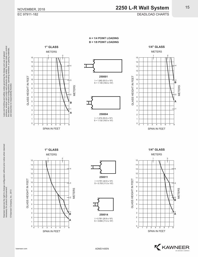
NOVEMBER, 2018DEADLOAD CHARTS
A = 1/4 POINT LOADINGB = 1/8 POINT LOADING
1" GLASSMETERS
SPAN IN FEET
GLA
SS
HE
IGH
T IN
FE
ET
ME
TER
S
1" GLASSMETERS
SPAN IN FEET
GLA
SS
HE
IGH
T IN
FE
ET
ME
TER
S
1/4" GLASSMETERS
SPAN IN FEET
GLA
SS
HE
IGH
T IN
FE
ET
ME
TER
S
1/4" GLASSMETERS
SPAN IN FEETG
LAS
S H
EIG
HT
IN F
EE
T
ME
TER
S
250004I = 1.274 (53.0 x 10⁴)S = 1.132 (18.5 x 10³)
250001I = 1.282 (53.3 x 10⁴)S = 1.140 (18.6 x 10³)
250014I = 0.781 (20.9 x 10⁴)S = 0.694 (11.4 x 10³)
250011I = 0.791 (32.9 x 10⁴)S = 0.703 (11.5 x 10³)
Law
s an
d bu
ildin
g an
d sa
fety
cod
es g
over
ning
the
desi
gn a
nd u
se o
f gla
zed
entra
nce,
win
dow
, and
cur
tain
wal
l pro
duct
s va
ry w
idel
y. K
awne
er d
oes
not c
ontro
l th
e se
lect
ion
of p
rodu
ct c
onfig
urat
ions
, ope
ratin
g ha
rdw
are,
or g
lazi
ng m
ater
ials
, an
d as
sum
es n
o re
spon
sibi
lity
ther
efor
.
Kaw
neer
rese
rves
the
right
to c
hang
e co
nfigu
ratio
n w
ithou
t prio
r not
ice
whe
n de
emed
nece
ssar
y fo
r pro
duct
impr
ovem
ent.
© K
awne
er C
ompa
ny, I
nc.,
2013
kawneer.com
16
EC 97911-182
3
00
1
2
1 2 3
4
5
6
7
8
9
11
10
12
4 5 76 8
A
B1
2
3
13
14
151 2
4
3
00
1
2
1 2 3
4
5
6
7
8
9
11
10
12
4 5 76 8
A1
B
2
3
13
14
151 2
4
2250 L-R Wall System
ADMD140EN
NOVEMBER, 2018DEADLOAD CHARTS
A = 1/4 POINT LOADINGB = 1/8 POINT LOADING
250510
250041
1" GLASSMETERS
SPAN IN FEET
GLA
SS
HE
IGH
T IN
FE
ET
ME
TER
S
1" GLASSMETERS
SPAN IN FEET
GLA
SS
HE
IGH
T IN
FE
ET
ME
TER
S250037
250510 with250029 ADAPTER
250511
250037 with250029 ADAPTER

Law
s an
d bu
ildin
g an
d sa
fety
cod
es g
over
ning
the
desi
gn a
nd u
se o
f gla
zed
entra
nce,
win
dow
, and
cur
tain
wal
l pro
duct
s va
ry w
idel
y. K
awne
er d
oes
not c
ontro
l th
e se
lect
ion
of p
rodu
ct c
onfig
urat
ions
, ope
ratin
g ha
rdw
are,
or g
lazi
ng m
ater
ials
, an
d as
sum
es n
o re
spon
sibi
lity
ther
efor
.
Kaw
neer
rese
rves
the
right
to c
hang
e co
nfigu
ratio
n w
ithou
t prio
r not
ice
whe
n de
emed
nece
ssar
y fo
r pro
duct
impr
ovem
ent.
© K
awne
er C
ompa
ny, I
nc.,
2013
kawneer.com
17
EC 97911-182
2-1/2"
3'-0
"4'
-0"
8'-0
"6'
-0"
9'-0
"
31'-3
"
5'-0"
2-1/
2"
2250 L-R Wall System
ADMD140EN
NOVEMBER, 2018THERMAL CHARTS
Project Specific U-FactorExample Calculation
(Based on single bay of Curtain Wall/Window Wall)
Vision Area
Example Glass U-Factor = 0.48 Btu/(ft2 x h x °F)
Vision Area = 5(9 + 8 + 4) = 105.0 ft
Total Area (Vision) = 5' 2-1/2"(9' 3-3/4" + 8' 2-1/2" + 4' 2-1/2") = 113.2 ft
Percent of Vision Glass = (Vision Area ÷ Total Area)100 = (105.0 ÷ 113.2)100 = 93%
Spandrel Area
Example Spandrel R-value = 15(ft2 x h x °F)/Btu
Spandrel Area = 5(6 + 3) = 45.0 ft
Total Area Spandrel = 5' 2-1/2"(6' 2-1/2" + 3' 3-3/4") = 49.6 ft
Percent of Spandrel = (Spandrel Area ÷ Total Area)100 = (45.0 ÷ 49.6)100 = 91%
D.L.O.
VISION
SPANDREL
VISION
SPANDREL
VISION
D.L
.O.
D.L
.O.
D.L
.O.
D.L
.O.
D.L
.O.
TYPICAL
TYP
ICA
L

Law
s an
d bu
ildin
g an
d sa
fety
cod
es g
over
ning
the
desi
gn a
nd u
se o
f gla
zed
entra
nce,
win
dow
, and
cur
tain
wal
l pro
duct
s va
ry w
idel
y. K
awne
er d
oes
not c
ontro
l th
e se
lect
ion
of p
rodu
ct c
onfig
urat
ions
, ope
ratin
g ha
rdw
are,
or g
lazi
ng m
ater
ials
, an
d as
sum
es n
o re
spon
sibi
lity
ther
efor
.
Kaw
neer
rese
rves
the
right
to c
hang
e co
nfigu
ratio
n w
ithou
t prio
r not
ice
whe
n de
emed
nece
ssar
y fo
r pro
duct
impr
ovem
ent.
© K
awne
er C
ompa
ny, I
nc.,
2013
kawneer.com
18
EC 97911-182
2250 L-R Wall System
ADMD140EN
NOVEMBER, 2018THERMAL CHARTS
Vision Area / Total Area (%)
0.53
93%
System U-factor vs Percent of Vision Area
COGU-factor
0.480.460.440.420.400.380.360.340.320.300.280.260.240.220.20
0.70
0.80
0.60
0.50
0.40
0.30
0.2095 90 85 80 75 70
Based on a single curtain wall bay of 93% vision glass and centerof glass U-factor of 0.48, System U-factor is equal to 0.53 Btu/(h·ft ·°F)
2
Vision Area Chart
Based on a single curtain wall bay of 91% spandrel and center ofspandrel R-value of 15, system U-factor is equal to 0.21 Btu/(h·ft ·°F)2
Spandrel Area Chart
Spandrel Area / Total Area (%)
0.21
91%
System U-factor vs Percent of Spandrel Area
SpandrelR-value
2.00
3.00
4.00
5.00
11.0015.0019.0030.00
0.60
0.50
0.40
0.30
0.20
95 90 85 80 75 700.10
Sys
tem
U-f
acto
r
Btu
Ih·f
t· °
F2
Sys
tem
U-f
acto
r
Btu
Ih·f
t· °
F2
EXAMPLE
(NOT FOR DESIGN)
EXAMPLE
(NOT FOR DESIGN)
Law
s an
d bu
ildin
g an
d sa
fety
cod
es g
over
ning
the
desi
gn a
nd u
se o
f gla
zed
entra
nce,
win
dow
, and
cur
tain
wal
l pro
duct
s va
ry w
idel
y. K
awne
er d
oes
not c
ontro
l th
e se
lect
ion
of p
rodu
ct c
onfig
urat
ions
, ope
ratin
g ha
rdw
are,
or g
lazi
ng m
ater
ials
, an
d as
sum
es n
o re
spon
sibi
lity
ther
efor
.
Kaw
neer
rese
rves
the
right
to c
hang
e co
nfigu
ratio
n w
ithou
t prio
r not
ice
whe
n de
emed
nece
ssar
y fo
r pro
duct
impr
ovem
ent.
© K
awne
er C
ompa
ny, I
nc.,
2013
kawneer.com
19
EC 97911-182
2250 L-R Wall System
ADMD140EN
NOVEMBER, 2018THERMAL CHARTS
Vision Area / Total Area (%)
COGU-factor
0.480.460.440.420.400.380.360.340.320.300.280.260.240.220.20
0.70
0.80
0.60
0.50
0.40
0.30
0.2095 90 85 80 75 70
0.75
0.65
0.55
0.45
0.35
0.25
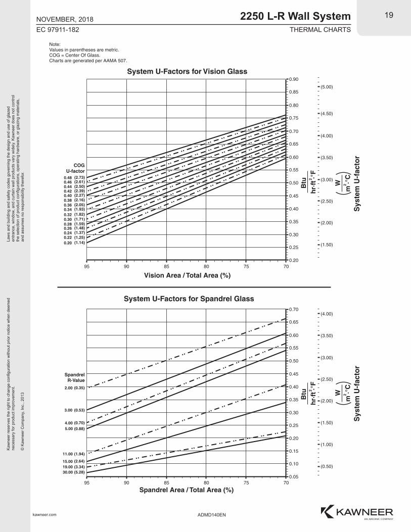
(2.73)(2.61)(2.50)(2.39)(2.27)(2.16)(2.05)(1.93)(1.82)(1.71)(1.59)(1.48)(1.37)(1.25)(1.14)
Note:Values in parentheses are metric.COG = Center Of Glass.Charts are generated per AAMA 507.
System U-Factors for Vision Glass
SpandrelR-Value
2.00
3.00
4.005.00
11.00
15.0019.0030.00
Spandrel Area / Total Area (%)
(0.35)
(0.53)
(0.70)(0.88)
(1.94)
(2.64)(3.34)(5.28)
System U-Factors for Spandrel GlassB
tuh
r·ft
·°F
2
W
Sys
tem
U-f
acto
rm
·°C
2
(4.00)
(4.50)
(3.50)
(3.00)
(2.50)
(1.50)
(2.00)
0.70
0.60
0.50
0.40
0.30
0.20
95 90 85 80 75 70
0.65
0.55
0.45
0.35
0.25
Btu
hr·
ft ·°
F2
W
Sys
tem
U-f
acto
rm
·°C
2
(4.00)
(3.50)
(3.00)
(2.50)
(1.50)
(2.00)
0.15
0.05
0.10 (0.50)
(1.00)
0.90
0.85(5.00)

Law
s an
d bu
ildin
g an
d sa
fety
cod
es g
over
ning
the
desi
gn a
nd u
se o
f gla
zed
entra
nce,
win
dow
, and
cur
tain
wal
l pro
duct
s va
ry w
idel
y. K
awne
er d
oes
not c
ontro
l th
e se
lect
ion
of p
rodu
ct c
onfig
urat
ions
, ope
ratin
g ha
rdw
are,
or g
lazi
ng m
ater
ials
, an
d as
sum
es n
o re
spon
sibi
lity
ther
efor
.
Kaw
neer
rese
rves
the
right
to c
hang
e co
nfigu
ratio
n w
ithou
t prio
r not
ice
whe
n de
emed
nece
ssar
y fo
r pro
duct
impr
ovem
ent.
© K
awne
er C
ompa
ny, I
nc.,
2013
kawneer.com
20
EC 97911-182
2250 L-R Wall System
ADMD140EN
NOVEMBER, 2018THERMAL CHARTS
Vision Area / Total Area (%)
COGSHGC
0.90
0.85
0.80
0.75
0.70
0.65
0.60
0.55
0.50
0.45
0.40
0.35
0.30
0.25
0.20
75
Sys
tem
SH
GC
0.90
0.85
System Solar Heat Gain Coefficient (SHGC) vs Percent of Vision Area
7085 8095 90
0.80
0.75
0.70
0.65
0.60
0.55
0.50
0.45
0.40
0.35
0.30
0.25
0.20
0.15
0.10
Charts are generated per AAMA 507.
Vision Area / Total Area (%)
COGVT
0.90
0.85
0.80
0.75
0.70
0.65
0.60
0.55
0.50
0.45
0.40
0.35
0.30
0.25
0.20
75
Sys
tem
VT
0.90
0.85
System Visible Transmittance (VT) vs Percent of Vision Area
7085 8095 90
0.80
0.75
0.70
0.65
0.60
0.55
0.50
0.45
0.40
0.35
0.30
0.25
0.20
0.15
0.10
Charts are generated per AAMA 507.

Law
s an
d bu
ildin
g an
d sa
fety
cod
es g
over
ning
the
desi
gn a
nd u
se o
f gla
zed
entra
nce,
win
dow
, and
cur
tain
wal
l pro
duct
s va
ry w
idel
y. K
awne
er d
oes
not c
ontro
l th
e se
lect
ion
of p
rodu
ct c
onfig
urat
ions
, ope
ratin
g ha
rdw
are,
or g
lazi
ng m
ater
ials
, an
d as
sum
es n
o re
spon
sibi
lity
ther
efor
.
Kaw
neer
rese
rves
the
right
to c
hang
e co
nfigu
ratio
n w
ithou
t prio
r not
ice
whe
n de
emed
nece
ssar
y fo
r pro
duct
impr
ovem
ent.
© K
awne
er C
ompa
ny, I
nc.,
2013
kawneer.com
21
EC 97911-182
2250 L-R Wall System
ADMD140EN
NOVEMBER, 2018THERMAL PERFORMANCE MATRIX (NFRC SIZE)
NOTE: For glass values that are not listed, linear interpolation is permitted.
1. U-Factors are determined in accordance with NFRC 100.2. SHGC and VT values are determined in accordance with NFRC 200.3. Glass properties are based on center of glass values and are obtained from your glass supplier.4. Overall U-Factor, SHGC, and VT Matricies are based on the standard NFRC specimen size of 2,000 mm wide by 2,000 mm high (78-3/4" by 78-3/4").
Thermal Transmittance1 (BTU/hr • ft 2 • °F)
SHGC Matrix 2 Visible Transmittance 2
Glass U-Factor 3
0.48
0.46
0.44
0.42
0.40
0.38
0.36
0.34
0.32
0.30
0.28
0.26
0.24
0.22
0.20
Overall U-Factor 4
0.57
0.55
0.53
0.51
0.50
0.48
0.46
0.44
0.43
0.41
0.39
0.38
0.36
0.34
0.32
Glass VT 3
0.90
0.85
0.80
0.75
0.70
0.65
0.60
0.55
0.50
0.45
0.40
0.35
0.30
0.25
0.20
Overall VT 4
0.82
0.77
0.73
0.68
0.64
0.59
0.55
0.50
0.45
0.41
0.36
0.32
0.27
0.23
0.18
Glass SHGC 3
0.75
0.70
0.65
0.60
0.55
0.50
0.45
0.40
0.35
0.30
0.25
0.20
0.15
0.10
0.05
Overall SHGC 4
0.70
0.66
0.61
0.57
0.52
0.48
0.43
0.38
0.34
0.29
0.25
0.20
0.16
0.11
0.07
FACTORS FOR CAPTURED MULLIONS

Law
s an
d bu
ildin
g an
d sa
fety
cod
es g
over
ning
the
desi
gn a
nd u
se o
f gla
zed
entra
nce,
win
dow
, and
cur
tain
wal
l pro
duct
s va
ry w
idel
y. K
awne
er d
oes
not c
ontro
l th
e se
lect
ion
of p
rodu
ct c
onfig
urat
ions
, ope
ratin
g ha
rdw
are,
or g
lazi
ng m
ater
ials
, an
d as
sum
es n
o re
spon
sibi
lity
ther
efor
.
Kaw
neer
rese
rves
the
right
to c
hang
e co
nfigu
ratio
n w
ithou
t prio
r not
ice
whe
n de
emed
nece
ssar
y fo
r pro
duct
impr
ovem
ent.
© K
awne
er C
ompa
ny, I
nc.,
2013
kawneer.com
22
EC 97911-182
2250 L-R Wall System
ADMD140EN
NOVEMBER, 2018
Vision Area / Total Area (%)
COGU-factor
0.480.460.440.420.400.380.360.340.320.300.280.260.240.220.20
0.70
0.80
0.60
0.50
0.40
0.30
0.2095 90 85 80 75 70
0.75
0.65
0.55
0.45
0.35
0.25
(2.73)(2.61)(2.50)(2.39)(2.27)(2.16)(2.05)(1.93)(1.82)(1.71)(1.59)(1.48)(1.37)(1.25)(1.14)
Note:Values in parentheses are metric.COG = Center Of Glass.Charts are generated per AAMA 507.
System U-Factors for SSG Vision Glass
SpandrelR-Value
2.00
3.00
4.00
5.00
11.00
15.00
19.0030.00
Spandrel Area / Total Area (%)
(0.35)
(0.53)
(0.70)
(0.88)
(1.94)
(2.64)
(3.34)(5.28)
System U-Factors for SSG Spandrel GlassB
tuh
r·ft
·°F
2
W
Sys
tem
U-f
acto
rm
·°C
2
(4.00)
(4.50)
(3.50)
(3.00)
(2.50)
(1.50)
(2.00)
0.70
0.60
0.50
0.40
0.30
0.20
95 90 85 80 75 70
0.65
0.55
0.45
0.35
0.25
Btu
hr·
ft ·°
F2
W
Sys
tem
U-f
acto
rm
·°C
2
(4.00)
(3.50)
(3.00)
(2.50)
(1.50)
(2.00)
0.15
0.05
0.10 (0.50)
(1.00)
0.90
0.85(5.00)
THERMAL CHARTS

Law
s an
d bu
ildin
g an
d sa
fety
cod
es g
over
ning
the
desi
gn a
nd u
se o
f gla
zed
entra
nce,
win
dow
, and
cur
tain
wal
l pro
duct
s va
ry w
idel
y. K
awne
er d
oes
not c
ontro
l th
e se
lect
ion
of p
rodu
ct c
onfig
urat
ions
, ope
ratin
g ha
rdw
are,
or g
lazi
ng m
ater
ials
, an
d as
sum
es n
o re
spon
sibi
lity
ther
efor
.
Kaw
neer
rese
rves
the
right
to c
hang
e co
nfigu
ratio
n w
ithou
t prio
r not
ice
whe
n de
emed
nece
ssar
y fo
r pro
duct
impr
ovem
ent.
© K
awne
er C
ompa
ny, I
nc.,
2013
kawneer.com
23
EC 97911-182
2250 L-R Wall System
ADMD140EN
NOVEMBER, 2018THERMAL CHARTS
Vision Area / Total Area (%)
COGSHGC
0.90
0.85
0.80
0.75
0.70
0.65
0.60
0.55
0.50
0.45
0.40
0.35
0.30
0.25
0.20
75
Sys
tem
SH
GC
0.90
0.85
System Solar Heat Gain Coefficient (SHGC) vs Percent of SSG Vision Area
7085 8095 90
0.80
0.75
0.70
0.65
0.60
0.55
0.50
0.45
0.40
0.35
0.30
0.25
0.20
0.15
0.10
Charts are generated per AAMA 507.
Vision Area / Total Area (%)
COGVT
0.90
0.85
0.80
0.75
0.70
0.65
0.60
0.55
0.50
0.45
0.40
0.35
0.30
0.25
0.20
75
Sys
tem
VT
0.90
0.85
System Visible Transmittance (VT) vs Percent of SSG Vision Area
7085 8095 90
0.80
0.75
0.70
0.65
0.60
0.55
0.50
0.45
0.40
0.35
0.30
0.25
0.20
0.15
0.10
Charts are generated per AAMA 507.
Law
s an
d bu
ildin
g an
d sa
fety
cod
es g
over
ning
the
desi
gn a
nd u
se o
f gla
zed
entra
nce,
win
dow
, and
cur
tain
wal
l pro
duct
s va
ry w
idel
y. K
awne
er d
oes
not c
ontro
l th
e se
lect
ion
of p
rodu
ct c
onfig
urat
ions
, ope
ratin
g ha
rdw
are,
or g
lazi
ng m
ater
ials
, an
d as
sum
es n
o re
spon
sibi
lity
ther
efor
.
Kaw
neer
rese
rves
the
right
to c
hang
e co
nfigu
ratio
n w
ithou
t prio
r not
ice
whe
n de
emed
nece
ssar
y fo
r pro
duct
impr
ovem
ent.
© K
awne
er C
ompa
ny, I
nc.,
2013
kawneer.com
24
EC 97911-182
2250 L-R Wall System
ADMD140EN
NOVEMBER, 2018
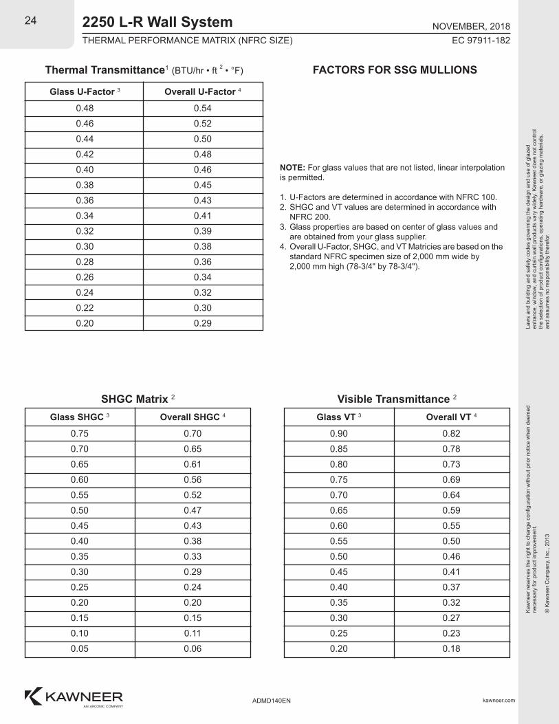
NOTE: For glass values that are not listed, linear interpolation is permitted.
1. U-Factors are determined in accordance with NFRC 100.2. SHGC and VT values are determined in accordance with NFRC 200.3. Glass properties are based on center of glass values and are obtained from your glass supplier.4. Overall U-Factor, SHGC, and VT Matricies are based on the standard NFRC specimen size of 2,000 mm wide by 2,000 mm high (78-3/4" by 78-3/4").
Thermal Transmittance1 (BTU/hr • ft 2 • °F)
SHGC Matrix 2 Visible Transmittance 2
Glass U-Factor 3
0.48
0.46
0.44
0.42
0.40
0.38
0.36
0.34
0.32
0.30
0.28
0.26
0.24
0.22
0.20
Overall U-Factor 4
0.54
0.52
0.50
0.48
0.46
0.45
0.43
0.41
0.39
0.38
0.36
0.34
0.32
0.30
0.29
Glass VT 3
0.90
0.85
0.80
0.75
0.70
0.65
0.60
0.55
0.50
0.45
0.40
0.35
0.30
0.25
0.20
Overall VT 4
0.82
0.78
0.73
0.69
0.64
0.59
0.55
0.50
0.46
0.41
0.37
0.32
0.27
0.23
0.18
Glass SHGC 3
0.75
0.70
0.65
0.60
0.55
0.50
0.45
0.40
0.35
0.30
0.25
0.20
0.15
0.10
0.05
Overall SHGC 4
0.70
0.65
0.61
0.56
0.52
0.47
0.43
0.38
0.33
0.29
0.24
0.20
0.15
0.11
0.06
FACTORS FOR SSG MULLIONS
THERMAL PERFORMANCE MATRIX (NFRC SIZE)