2/2-way Globe Control Valve with stainless steel design ... · 2/2-way Globe Control Valve with...
14
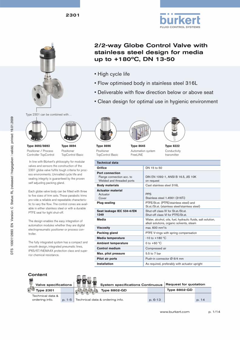
2301 p. 1/14 www.burkert.com 2/2-way Globe Control Valve with stainless steel design for media up to +180ºC, DN 13-50 In line with Bürkert’s philosophy for modular valves and sensors the construction of the 2301 globe valve fulfils tough criteria for proc- ess environments. Unrivalled cycle life and sealing integrity is guaranteed by the proven self adjusting packing gland. Each globe valve body can be fitted with three to five sizes of trim sets. These parabolic trims pro-vide a reliable and repeatable characteris- tic to vary the flow. The control cones are avail- able in either stainless steel or with a durable PTFE seal for tight shut-off. The design enables the easy integration of automation modules whether they are digital electropneumatic positioner or process con- troller. The fully integrated system has a compact and smooth design, integrated pneumatic lines, IP65/67/NEMA4X protection class and supe- rior chemical resistance. Type 2301 can be combined with… Technical data Orifice DN 15 to 50 Port connection Flange connection acc. to Welded and threaded ports DIN EN 1092-1, ANSI B 16.5, JIS 10K on request Body materials Cast stainless steel 316L Actuator material Actuator Cover PPS Stainless steel 1.4561 (316Ti) Plug sealing PTFE/St.st. (PTFE/stainless steel) and St.st./St.st. (stainless steel/stainless steel) Seat leakage IEC 534-4/EN 1349 Shut-off class IV for St.st./St.st. Shut-off class VI for PTFE/St.st. Media Water, alcohol, oils, fuel, hydraulic fluids, salt solution, alkali solutions, organic solvents, steam Viscosity max. 600 mm 2 /s Packing gland PTFE V-rings with spring compensation Media temperature -10 to +180 ºC Ambient temperature 0 to +60 ºC Control medium Compressed air Max. pilot pressure 5.5 to 7 bar Pilot air ports Push-in connector Ø 6/4 mm Installation As required, preferably with actuator upright Type 8222 Conductivity transmitter Type 8645 Automation system FreeLINE • High cycle life • Flow optimised body in stainless steel 316L • Deliverable with flow direction below or above seat • Clean design for optimal use in hygienic environment Valve specifications System specifications Continuous Request for quotation Type 2301 Type 8802-GD Type 8802-GD Technical data & ordering info. p. 1-5 Technical data & ordering info. p. 6-13 p. 14 Content Type 8692/8693 Positioner / Process Controller TopControl Type 8694 Positioner TopControl Basic Type 8696 Positioner TopControl Basic
-
Upload
truongnhan -
Category
Documents
-
view
217 -
download
3
Transcript of 2/2-way Globe Control Valve with stainless steel design ... · 2/2-way Globe Control Valve with...
2301
p. 1/14www.burkert.com
2/2-way Globe Control Valve with stainless steel design for media up to +180ºC, DN 13-50
In line with Bürkert’s philosophy for modular
valves and sensors the construction of the
2301 globe valve fulfi ls tough criteria for proc-
ess environments. Unrivalled cycle life and
sealing integrity is guaranteed by the proven
self adjusting packing gland.
Each globe valve body can be fi tted with three
to fi ve sizes of trim sets. These parabolic trims
pro-vide a reliable and repeatable characteris-
tic to vary the fl ow. The control cones are avail-
able in either stainless steel or with a durable
PTFE seal for tight shut-off.
The design enables the easy integration of
automation modules whether they are digital
electropneumatic positioner or process con-
troller.
The fully integrated system has a compact and
smooth design, integrated pneumatic lines,
IP65/67/NEMA4X protection class and supe-
rior chemical resistance.
Type 2301 can be combined with…
Technical data
Orifi ce DN 15 to 50
Port connection
Flange connection acc. to
Welded and threaded ports
DIN EN 1092-1, ANSI B 16.5, JIS 10K
on request
Body materials Cast stainless steel 316L
Actuator material
Actuator
Cover
PPS
Stainless steel 1.4561 (316Ti)
Plug sealing PTFE/St.st. (PTFE/stainless steel) and
St.st./St.st. (stainless steel/stainless steel)
Seat leakage IEC 534-4/EN
1349
Shut-off class IV for St.st./St.st.
Shut-off class VI for PTFE/St.st.
Media Water, alcohol, oils, fuel, hydraulic fl uids, salt solution,
alkali solutions, organic solvents, steam
Viscosity max. 600 mm2/s
Packing gland PTFE V-rings with spring compensation
Media temperature -10 to +180 ºC
Ambient temperature 0 to +60 ºC
Control medium Compressed air
Max. pilot pressure 5.5 to 7 bar
Pilot air ports Push-in connector Ø 6/4 mm
Installation As required, preferably with actuator upright
Type 8222
Conductivity
transmitter
Type 8645
Automation system
FreeLINE
• High cycle life
• Flow optimised body in stainless steel 316L
• Deliverable with fl ow direction below or above seat
• Clean design for optimal use in hygienic environment
Valve specifi cations System specifi cations Continuous Request for quotation
Type 2301 Type 8802-GD Type 8802-GD
Technical data & ordering info. p. 1-5 Technical data & ordering info. p. 6-13 p. 14
Content
Type 8692/8693
Positioner / Process
Controller TopControl
Type 8694
Positioner
TopControl Basic
Type 8696
Positioner
TopControl Basic
2301
p. 2/14
Technical data Type 2301 Globe Control Valve, continued
Kvs values
Port size (tube) Orifi ce DN (seat) [mm]
ISO, DIN BS, ASME
[mm] [inch] 04 06 08 10 15 20 25 32 40 50
10 1/2” 0.5 1.2 2.0 2.7 – – – – – –
15 3/4” 0.5 1.2 2.1 3.1 3.2 – – – – –
20 1” – – – 3.2 5.2 7.5 – – – –
25 – – – – – 5.3 7.2 11.6 – – –
32 1 1/2” – – – – – 5.0 9.5 13.6 – –
40 2” – – – – – – 9.7 13.5 16.7 –
50 2 1/2” – – – – – – – 15.8 18.6 27.9
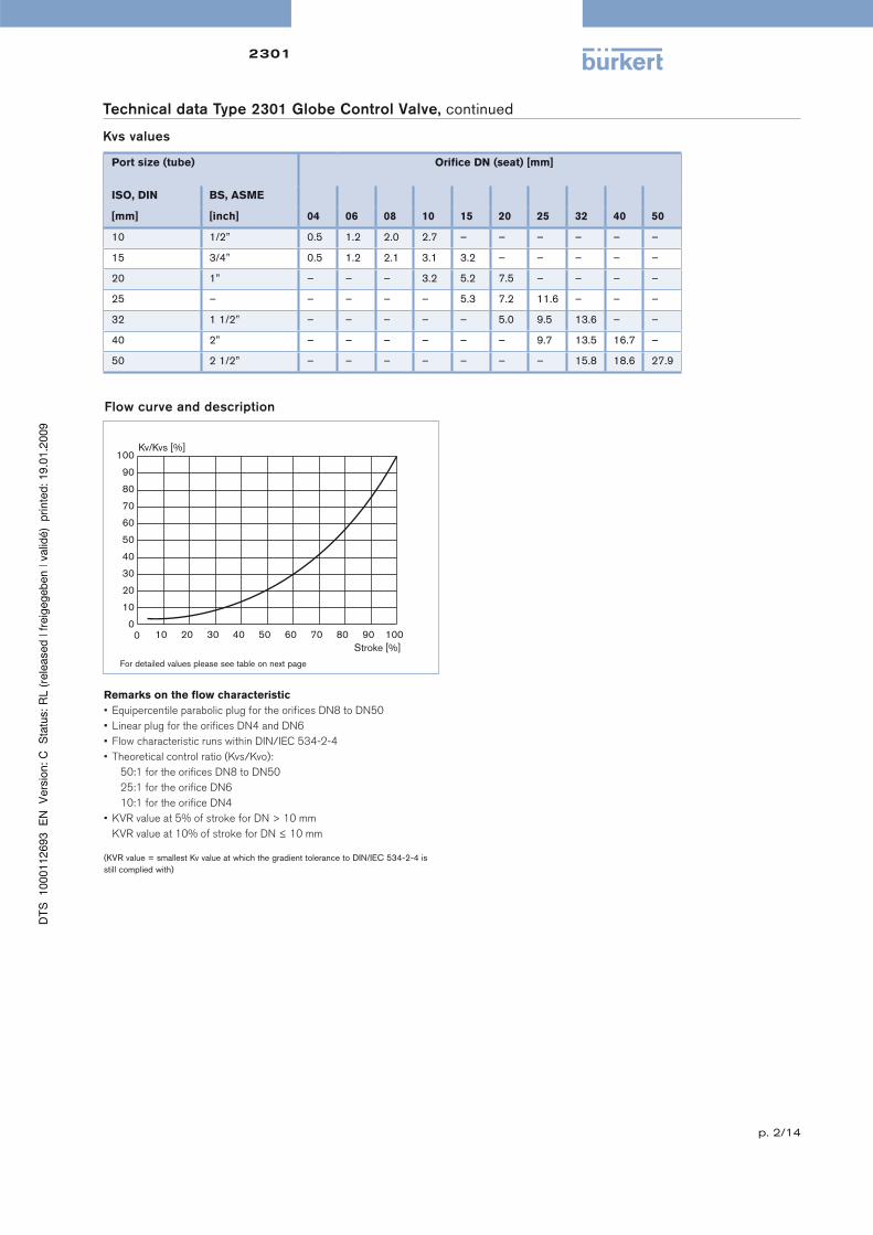
Flow curve and description
Remarks on the fl ow characteristic
• Equipercentile parabolic plug for the orifi ces DN8 to DN50
• Linear plug for the orifi ces DN4 and DN6
• Flow characteristic runs within DIN/IEC 534-2-4
• Theoretical control ratio (Kvs/Kvo):
50:1 for the orifi ces DN8 to DN50
25:1 for the orifi ce DN6
10:1 for the orifi ce DN4
• KVR value at 5% of stroke for DN > 10 mm
KVR value at 10% of stroke for DN ≤ 10 mm
(KVR value = smallest Kv value at which the gradient tolerance to DIN/IEC 534-2-4 is
still complied with)
100
90
80
70
60
50
40
30
20
10
00 10 20 30 40 50 60 70 80 90 100
Kv/Kvs [%]
Stroke [%]
For detailed values please see table on next page
2301
p. 3/14
Technical data Type 2301 Globe Control Valve, continued
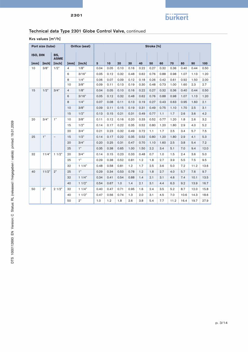
Kvs values [m3/h]
Port size (tube) Orifi ce (seat) Stroke [%]
ISO, DIN BS, ASME
[mm] [inch] [inch] [mm] [inch] 5 10 20 30 40 50 60 70 80 90 100
10 3/8” 1/2” 4 1/8” 0.04 0.05 0.10 0.16 0.22 0.27 0.32 0.36 0.40 0.44 0.50
6 3/16” 0.05 0.12 0.32 0.48 0.62 0.76 0.88 0.98 1.07 1.13 1.20
8 1/4” 0.06 0.07 0.09 0.12 0.18 0.26 0.42 0.61 0.92 1.50 2.00
10 3/8” 0.09 0.11 0.13 0.19 0.30 0.48 0.73 1.00 1.60 2.3 2.7
15 1/2” 3/4” 4 1/8” 0.04 0.05 0.10 0.16 0.22 0.27 0.32 0.36 0.40 0.44 0.50
6 3/16” 0.05 0.12 0.32 0.48 0.62 0.76 0.88 0.98 1.07 1.13 1.20
8 1/4” 0.07 0.08 0.11 0.13 0.19 0.27 0.43 0.63 0.95 1.60 2.1
10 3/8” 0.09 0.11 0.15 0.19 0.31 0.49 0.75 1.10 1.70 2.5 3.1
15 1/2” 0.13 0.15 0.21 0.31 0.49 0.77 1.1 1.7 2.6 3.6 4.2
20 3/4” 1” 10 3/8” 0.11 0.12 0.16 0.20 0.33 0.52 0.77 1.20 1.8 2.6 3.2
15 1/2” 0.14 0.17 0.22 0.35 0.52 0.80 1.20 1.80 2.9 4.0 5.2
20 3/4” 0.21 0.23 0.32 0.49 0.72 1.1 1.7 2.5 3.4 5.7 7.5
25 1” – 15 1/2” 0.14 0.17 0.22 0.35 0.52 0.80 1.20 1.80 2.9 4.1 5.3
20 3/4” 0.20 0.25 0.31 0.47 0.70 1.10 1.60 2.5 3.8 5.4 7.2
25 1” 0.35 0.38 0.65 1.00 1.50 2.2 3.4 5.1 7.0 9.4 12.0
32 11/4” 1 1/2” 20 3/4” 0.14 0.15 0.23 0.33 0.48 0.7 1.0 1.5 2.4 3.6 5.0
25 1” 0.29 0.38 0.52 0.81 1.2 1.8 2.7 3.9 5.5 7.5 9.5
32 1 1/4” 0.48 0.58 0.81 1.2 1.7 2.5 3.6 5.0 7.2 11.2 13.6
40 11/2” 2” 25 1” 0.29 0.34 0.53 0.78 1.2 1.8 2.7 4.0 5.7 7.6 9.7
32 1 1/4” 0.34 0.41 0.54 0.88 1.4 2.1 3.1 4.6 7.4 10.1 13.5
40 1 1/2” 0.54 0.67 1.0 1.4 2.1 3.1 4.4 6.3 9.2 13.9 16.7
50 2” 2 1/2” 32 1 1/4” 0.40 0.47 0.71 0.95 1.6 2.4 3.5 5.2 8.7 12.0 15.8
40 1 1/2” 0.47 0.56 0.74 1.3 2.0 3.1 4.5 7.0 10.6 14.3 18.6
50 2” 1.0 1.2 1.8 2.6 3.8 5.4 7.7 11.2 16.4 19.7 27.9
2301
p. 4/14
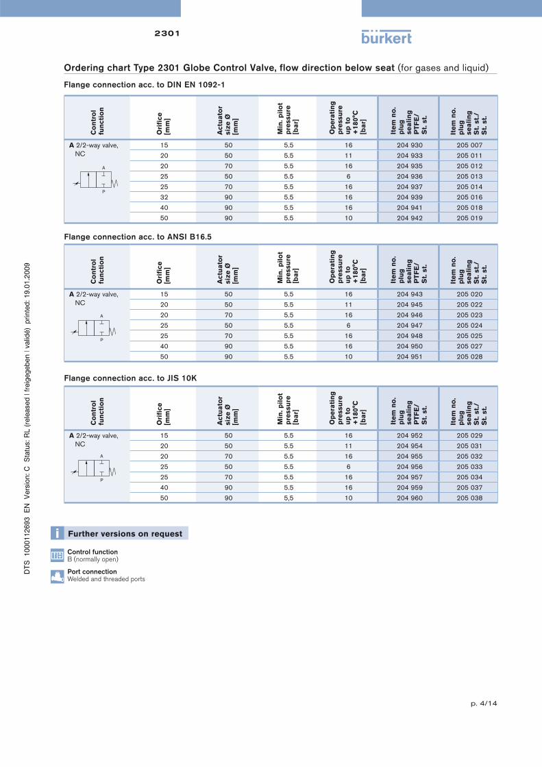
Ordering chart Type 2301 Globe Control Valve, flow direction below seat (for gases and liquid)
Flange connection acc. to DIN EN 1092-1
Control functionB (normally open)
Port connectionWelded and threaded ports
Co
ntr
ol
fun
cti
on
Ori
fi ce
[mm
]
Actu
ato
r siz
e Ø
[m
m]
Min
. p
ilo
t p
ressu
re
[ba
r]
Op
era
tin
g
pre
ssu
re
up
to
+
180°C
[b
ar]
Ite
m n
o.
plu
g
se
ali
ng
P
TF
E/
St.
st.
Ite
m n
o.
plu
g
se
ali
ng
S
t. s
t./
St.
st.
A 2/2-way valve,
NC
15 50 5.5 16 204 930 205 007
20 50 5.5 11 204 933 205 011
20 70 5.5 16 204 935 205 012
25 50 5.5 6 204 936 205 013
25 70 5.5 16 204 937 205 014
32 90 5.5 16 204 939 205 016
40 90 5.5 16 204 941 205 018
50 90 5.5 10 204 942 205 019
Flange connection acc. to ANSI B16.5
Co
ntr
ol
fun
cti
on
Ori
fi ce
[mm
]
Actu
ato
r siz
e Ø
[m
m]
Min
. p
ilo
t p
ressu
re
[ba
r]
Op
era
tin
g
pre
ssu
re
up
to
+
180°C
[b
ar]
Ite
m n
o.
plu
g
se
ali
ng
P
TF
E/
St.
st.
Ite
m n
o.
plu
g
se
ali
ng
S
t. s
t./
St.
st.
A 2/2-way valve,
NC
15 50 5.5 16 204 943 205 020
20 50 5.5 11 204 945 205 022
20 70 5.5 16 204 946 205 023
25 50 5.5 6 204 947 205 024
25 70 5.5 16 204 948 205 025
40 90 5.5 16 204 950 205 027
50 90 5.5 10 204 951 205 028
Flange connection acc. to JIS 10K
Co
ntr
ol
fun
cti
on
Ori
fi ce
[mm
]
Actu
ato
r siz
e Ø
[m
m]
Min
. p
ilo
t p
ressu
re
[ba
r]
Op
era
tin
g
pre
ssu
re
up
to
+
180°C
[b
ar]
Ite
m n
o.
plu
g
se
ali
ng
P
TF
E/
St.
st.
Ite
m n
o.
plu
g
se
ali
ng
S
t. s
t./
St.
st.
A 2/2-way valve,
NC
15 50 5.5 16 204 952 205 029
20 50 5.5 11 204 954 205 031
20 70 5.5 16 204 955 205 032
25 50 5.5 6 204 956 205 033
25 70 5.5 16 204 957 205 034
40 90 5.5 16 204 959 205 037
50 90 5,5 10 204 960 205 038
2301
p. 5/14
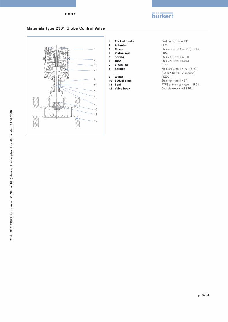
1 Pilot air ports Push-in connector PP
2 Actuator PPS
3 Cover Stainless steel 1.4561 (316Ti)
4 Piston seal FKM
5 Spring Stainless steel 1.4310
6 Tube Stainless steel 1.4404
7 V-sealing PTFE
8 Spindle Stainless steel 1.4401 (316)/
(1.4404 (316L) on request)
9 Wiper PEEK
10 Swivel plate Stainless steel 1.4571
11 Seal PTFE or stainless steel 1.4571
12 Valve body Cast stainless steel 316L
Materials Type 2301 Globe Control Valve
1
2
3
4
5
6
7
8
9
10
11
12
p. 6/14
2301System Continuous 8802-GD
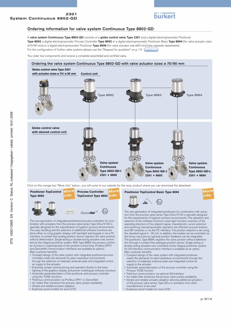
Ordering information for valve system Continuous Type 8802-GD
A valve system Continuous Type 8802-GD consists of a globe control valve Type 2301 and a digital electropneumatic Positioner
Type 8692, a digital electropneumatic Process Controller Type 8693 or a digital electropneumatic Positioner Basic Type 8694 (for valve actuator sizes
ø70/90 mm) or a digital electropneumatic Positioner Type 8696 (for valve actuator size ø50 mm) (see separate datasheets).
For the confi guration of further valve systems please use the "Request for quotation" on p. 14
You order two components and receive a complete assembled and certifi ed valve.
Globe control valve Type 2301
with actuator sizes ø 70/ ø 90 mm
Globe control valve
with desired control unit
Ordering the valve system Continuous Type 8802-GD with valve actuator sizes ø 70/90 mm
Control unit
Click on the orange box "More info." below... you will come to our website for the resp. product where you can download the datasheet.
Type 8692 Type 8693 Type 8694
Valve system
Continuous
Type 8802-GD-I
2301 + 8692
Valve system
Continuous
Type 8802-GD-J
2301 + 8693
Valve system
Continuous
Type 8802-GD-L
2301 + 8694
Positioner TopControl
Type 8692
Process Controller
TopControl Type 8693
Positioner TopControl Basic Type 8694
The new generation of integrated positioners/process controllers for com-bination with actuators from the process valve series Type 23xx/2103 is specially designed for the requirements of hygienic process environments. The easy handling and the selection of additional software functions are done either on a big graphic display with backlight and keypad or via a PC interface. A contact-free analog position sensor registers the valve position without deterioration. Single-acting or double-acting actuators are control-led via the integral positioner system. With Type 8693, the process control-ler function is superimposed on the position control loop. Profi bus DPV1 and DeviceNet communication interfaces are available as options.Main customer benefi ts:• Compact design of the valve system with integrated positioner/process controller meets the demands for plant washdown environments through the selection of materials, external seals and integrated control air supply to the actuator• Extremely simple commissioning and operation thanks to the back- lighting of the graphics display and proven multilingual software structure• Automatic parameterisation of the positioner and process controller using the TUNE functions• Field bus communication via Profi bus DPV1 or DeviceNet• Air intake fi lter enhances the process valve system availability• Simple and reliable actuator adaption• Explosion-proof models for zone 2/22
The new generation of integrated positioners for combination with actua-tors from the process valve series Type 23xx/2103 is specially designed for the requirements of hygienic process environments. The operation and selection of the software functions close tight function, inversion of the operating direction of the setpoint signal, characteristic curves selection and switching manual/automatic operation are effected via push-buttons and DIP switches or via the PC interface. The position setpoint is set using the standard signal 4 - 20 mA. In addition, the enable can be controlled via the binary input and an optional position feedback can be integrated. The positioner, Type 8694, registers the valve position without deteriora-tion through a contact-free analogue position sensor. Single-acting or double-acting actuators are controlled via the integral positioner system. An AS-Interface communication interface is available as an option.Main customer benefi ts:• Compact design of the valve system with integrated positioner meets the demands for plant washdown environments through the selection of materials, external seals and integrated control air supply to the actuator• Automatic parameterisation of the process controller using the Process TUNE function• Field bus communication via optional AS-Interface• Air intake fi lter enhances the process valve system availability• Simple and reliable actuator adaption allowing additional actuators of the process valve series, Type 20xx or actuators from other manufacturers to be used• Explosion-proof models for zone 2/22
p. 7/14
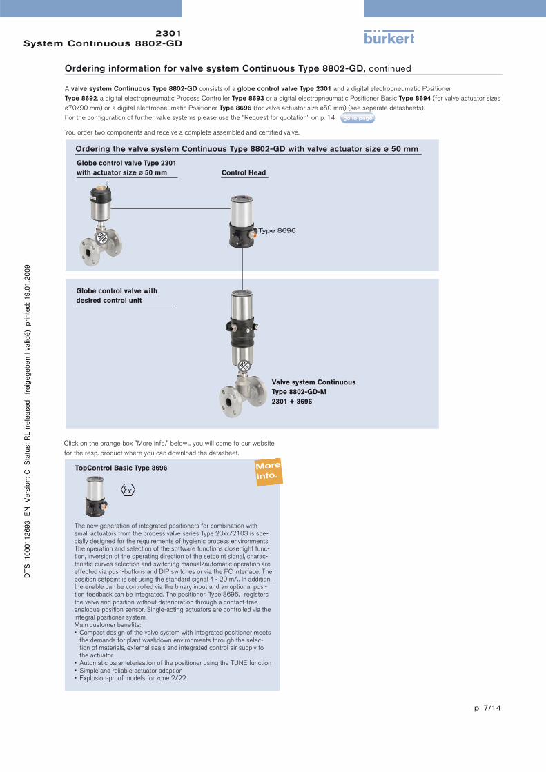
2301System Continuous 8802-GD
Control Head
Globe control valve Type 2301
with actuator size ø 50 mm
Globe control valve with
desired control unit
Valve system Continuous
Type 8802-GD-M
2301 + 8696
Ordering the valve system Continuous Type 8802-GD with valve actuator size ø 50 mm
Type 8696
Ordering information for valve system Continuous Type 8802-GD, continued
A valve system Continuous Type 8802-GD consists of a globe control valve Type 2301 and a digital electropneumatic Positioner
Type 8692, a digital electropneumatic Process Controller Type 8693 or a digital electropneumatic Positioner Basic Type 8694 (for valve actuator sizes
ø70/90 mm) or a digital electropneumatic Positioner Type 8696 (for valve actuator size ø50 mm) (see separate datasheets).
For the confi guration of further valve systems please use the "Request for quotation" on p. 14
You order two components and receive a complete assembled and certifi ed valve.
TopControl Basic Type 8696
The new generation of integrated positioners for combination with small actuators from the process valve series Type 23xx/2103 is spe-cially designed for the requirements of hygienic process environments. The operation and selection of the software functions close tight func-tion, inversion of the operating direction of the setpoint signal, charac-teristic curves selection and switching manual/automatic operation are effected via push-buttons and DIP switches or via the PC interface. The position setpoint is set using the standard signal 4 - 20 mA. In addition, the enable can be controlled via the binary input and an optional posi-tion feedback can be integrated. The positioner, Type 8696, , registers the valve end position without deterioration through a contact-free analogue position sensor. Single-acting actuators are controlled via the integral positioner system.Main customer benefi ts:• Compact design of the valve system with integrated positioner meets the demands for plant washdown environments through the selec- tion of materials, external seals and integrated control air supply to the actuator• Automatic parameterisation of the positioner using the TUNE function• Simple and reliable actuator adaption• Explosion-proof models for zone 2/22
Click on the orange box "More info." below... you will come to our website
for the resp. product where you can download the datasheet.
p. 8/14
2301System Continuous 8802-GD
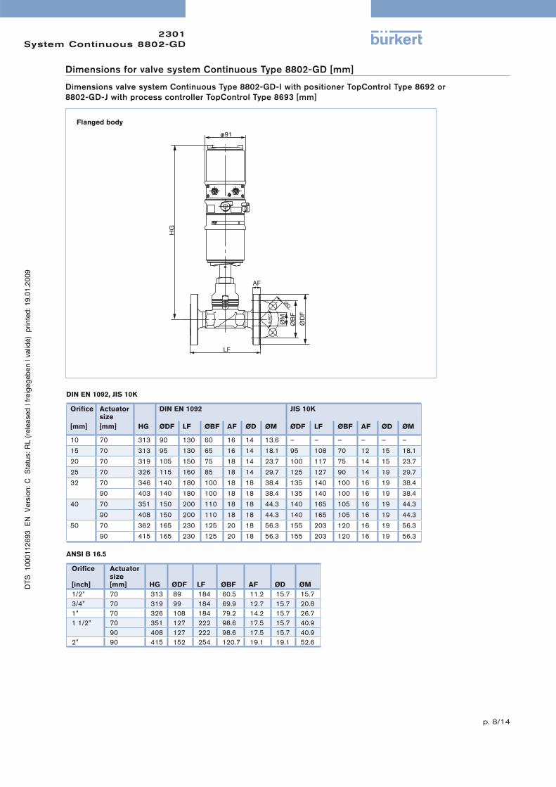
Flanged body
Orifi ce
Actuator size
DIN EN 1092 JIS 10K
[mm] [mm] HG ØDF LF ØBF AF ØD ØM ØDF LF ØBF AF ØD ØM
10 70 313 90 130 60 16 14 13.6 – – – – – –
15 70 313 95 130 65 16 14 18.1 95 108 70 12 15 18.1
20 70 319 105 150 75 18 14 23.7 100 117 75 14 15 23.7
25 70 326 115 160 85 18 14 29.7 125 127 90 14 19 29.7
32 70 346 140 180 100 18 18 38.4 135 140 100 16 19 38.4
90 403 140 180 100 18 18 38.4 135 140 100 16 19 38.4
40 70 351 150 200 110 18 18 44.3 140 165 105 16 19 44.3
90 408 150 200 110 18 18 44.3 140 165 105 16 19 44.3
50 70 362 165 230 125 20 18 56.3 155 203 120 16 19 56.3
90 415 165 230 125 20 18 56.3 155 203 120 16 19 56.3
Orifi ce
[inch]
Actuator size[mm] HG ØDF LF ØBF AF ØD ØM
1/2” 70 313 89 184 60.5 11.2 15.7 15.7
3/4” 70 319 99 184 69.9 12.7 15.7 20.8
1” 70 326 108 184 79.2 14.2 15.7 26.7
1 1/2” 70 351 127 222 98.6 17.5 15.7 40.9
90 408 127 222 98.6 17.5 15.7 40.9
2” 90 415 152 254 120.7 19.1 19.1 52.6
DIN EN 1092, JIS 10K
ANSI B 16.5
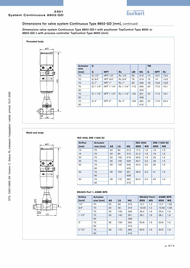
Dimensions for valve system Continuous Type 8802-GD [mm]
Dimensions valve system Continuous Type 8802-GD-I with positioner TopControl Type 8692 or
8802-GD-J with process controller TopControl Type 8693 [mm]
p. 9/14
2301System Continuous 8802-GD
Threaded body
Weld end body
Actuator size
G TM
[mm] G NPT Rc LM HG G NPT Rc
70 G 1/2” NPT 1/2” Rc 1/2” 65 313 14 13.7 13.2
70 G 3/4” NPT 3/4” Rc 3/4” 75 319 16 14 14.5
70 G 1” NPT 1” Rc 1” 90 326 18 16.8 16.8
70 G 1 1/4” NPT 1 1/4” Rc 1 1/4” 110 346 20 17.3 19.1
90 403
70 G 1 1/2” NPT 1 1/2” Rc 1 1/2” 120 351 22 17.3 19.1
90 408
70 G 2” NPT 2” Rc 2” 150 362 24 17.6 23.4
90 415
Orifi ce Actuator ISO 4200 DIN 11850 S2
[mm] size [mm] AS LS HG ØDS WS ØDS WS
10 70 20 90 313 17.2 1.6 13 1.5
15 70 20 90 313 21.3 1.6 19 1.5
20 70 20 100 319 26.9 1.6 23 1.5
25 70 26 130 326 33.7 2.0 29 1.5
32 70 26 140 346 42.4 2.0 35 1.5
90 403
40 70 26 150 351 48.3 2.0 41 1.5
90 408
50 70 26 175 362 60.3 2.0 53 1.5
90 415
ISO 4200, DIN 11850 S2
BS4825 Part 1, ASME BPE
Orifi ce Actuator BS4825 Part1 ASME BPE
[inch] size [mm] AS LS HG ØDS WS ØDS WS
1/2” 70 20 90 313 12.7 1.2 12.7 1.65
3/4” 70 20 90 319 19.05 1.2 19.05 1.65
1” 70 20 100 326 25.4 1.6 25.4 1.6
1 1/2” 70 26 140 351 38.1 1.6 38.1 1.6
90 408
2” 70 26 150 362 50.8 1.6 50.8 1.6
90 415
2 1/2” 70 26 175 362 63.5 1.6 63.5 1.6
90 415
Dimensions for valve system Continuous Type 8802-GD [mm], continued
Dimensions valve system Continuous Type 8802-GD-I with positioner TopControl Type 8692 or
8802-GD-J with process controller TopControl Type 8693 [mm]
p. 10/14
2301System Continuous 8802-GD
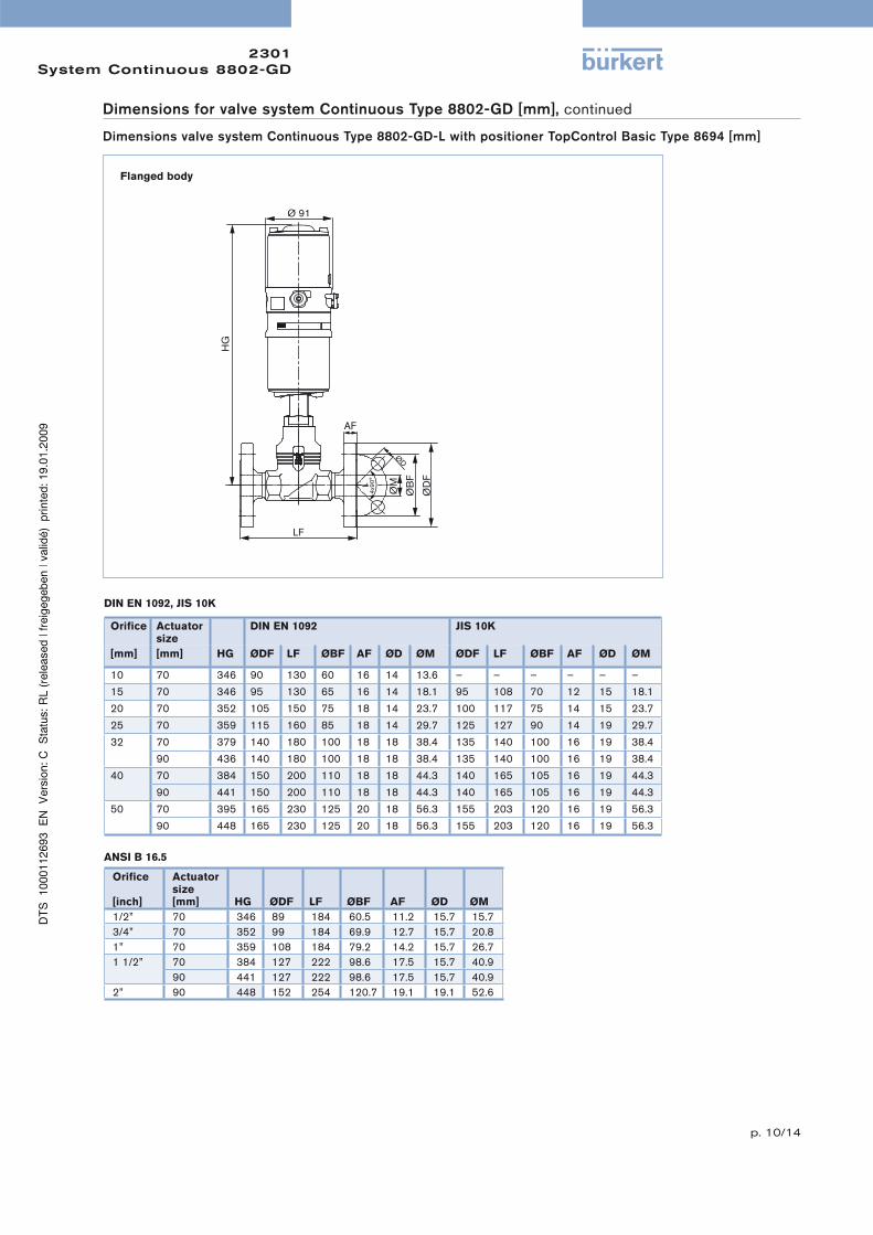
Dimensions for valve system Continuous Type 8802-GD [mm], continued
Dimensions valve system Continuous Type 8802-GD-L with positioner TopControl Basic Type 8694 [mm]
Flanged body
Orifi ce
Actuator size
DIN EN 1092 JIS 10K
[mm] [mm] HG ØDF LF ØBF AF ØD ØM ØDF LF ØBF AF ØD ØM
10 70 346 90 130 60 16 14 13.6 – – – – – –
15 70 346 95 130 65 16 14 18.1 95 108 70 12 15 18.1
20 70 352 105 150 75 18 14 23.7 100 117 75 14 15 23.7
25 70 359 115 160 85 18 14 29.7 125 127 90 14 19 29.7
32 70 379 140 180 100 18 18 38.4 135 140 100 16 19 38.4
90 436 140 180 100 18 18 38.4 135 140 100 16 19 38.4
40 70 384 150 200 110 18 18 44.3 140 165 105 16 19 44.3
90 441 150 200 110 18 18 44.3 140 165 105 16 19 44.3
50 70 395 165 230 125 20 18 56.3 155 203 120 16 19 56.3
90 448 165 230 125 20 18 56.3 155 203 120 16 19 56.3
Orifi ce
[inch]
Actuator size[mm] HG ØDF LF ØBF AF ØD ØM
1/2” 70 346 89 184 60.5 11.2 15.7 15.7
3/4” 70 352 99 184 69.9 12.7 15.7 20.8
1” 70 359 108 184 79.2 14.2 15.7 26.7
1 1/2” 70 384 127 222 98.6 17.5 15.7 40.9
90 441 127 222 98.6 17.5 15.7 40.9
2” 90 448 152 254 120.7 19.1 19.1 52.6
DIN EN 1092, JIS 10K
ANSI B 16.5
p. 11/14
2301System Continuous 8802-GD
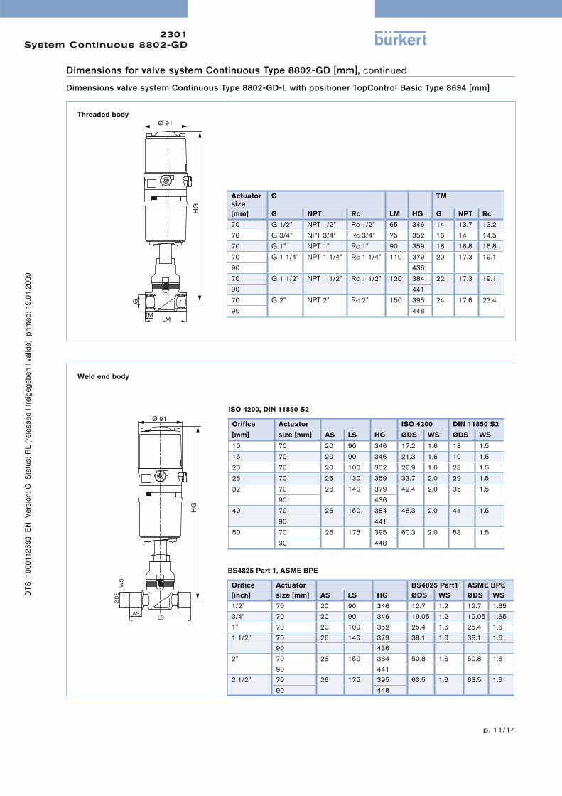
Dimensions for valve system Continuous Type 8802-GD [mm], continued
Dimensions valve system Continuous Type 8802-GD-L with positioner TopControl Basic Type 8694 [mm]
Threaded body
Weld end body
Actuator size
G TM
[mm] G NPT Rc LM HG G NPT Rc
70 G 1/2” NPT 1/2” Rc 1/2” 65 346 14 13.7 13.2
70 G 3/4” NPT 3/4” Rc 3/4” 75 352 16 14 14.5
70 G 1” NPT 1” Rc 1” 90 359 18 16.8 16.8
70 G 1 1/4” NPT 1 1/4” Rc 1 1/4” 110 379 20 17.3 19.1
90 436
70 G 1 1/2” NPT 1 1/2” Rc 1 1/2” 120 384 22 17.3 19.1
90 441
70 G 2” NPT 2” Rc 2” 150 395 24 17.6 23.4
90 448
Orifi ce Actuator ISO 4200 DIN 11850 S2
[mm] size [mm] AS LS HG ØDS WS ØDS WS
10 70 20 90 346 17.2 1.6 13 1.5
15 70 20 90 346 21.3 1.6 19 1.5
20 70 20 100 352 26.9 1.6 23 1.5
25 70 26 130 359 33.7 2.0 29 1.5
32 70 26 140 379 42.4 2.0 35 1.5
90 436
40 70 26 150 384 48.3 2.0 41 1.5
90 441
50 70 26 175 395 60.3 2.0 53 1.5
90 448
ISO 4200, DIN 11850 S2
BS4825 Part 1, ASME BPE
Orifi ce Actuator BS4825 Part1 ASME BPE
[inch] size [mm] AS LS HG ØDS WS ØDS WS
1/2” 70 20 90 346 12.7 1.2 12.7 1.65
3/4” 70 20 90 346 19.05 1.2 19.05 1.65
1” 70 20 100 352 25.4 1.6 25.4 1.6
1 1/2” 70 26 140 379 38.1 1.6 38.1 1.6
90 436
2” 70 26 150 384 50.8 1.6 50.8 1.6
90 441
2 1/2” 70 26 175 395 63.5 1.6 63.5 1.6
90 448
p. 12/14
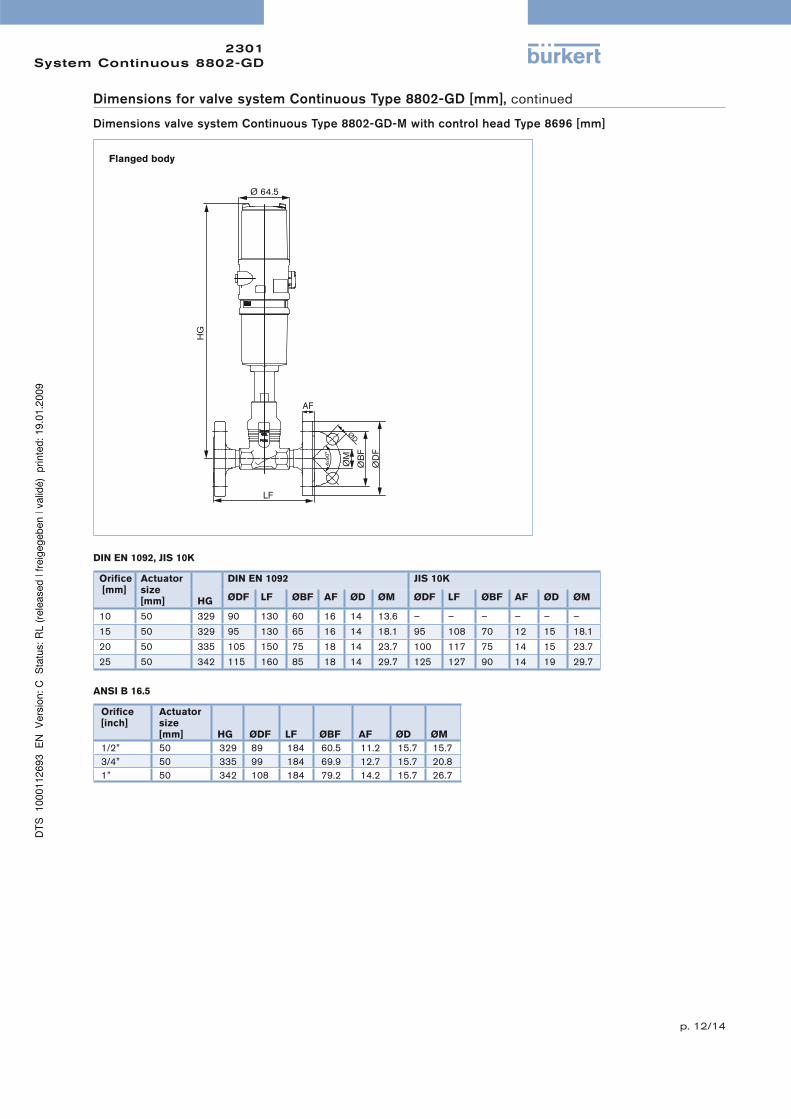
2301System Continuous 8802-GD
Flanged body
Orifi ce [mm]
Actuator size[mm] HG
DIN EN 1092 JIS 10K
ØDF LF ØBF AF ØD ØM ØDF LF ØBF AF ØD ØM
10 50 329 90 130 60 16 14 13.6 – – – – – –
15 50 329 95 130 65 16 14 18.1 95 108 70 12 15 18.1
20 50 335 105 150 75 18 14 23.7 100 117 75 14 15 23.7
25 50 342 115 160 85 18 14 29.7 125 127 90 14 19 29.7
Orifi ce[inch]
Actuator size[mm] HG ØDF LF ØBF AF ØD ØM
1/2” 50 329 89 184 60.5 11.2 15.7 15.7
3/4” 50 335 99 184 69.9 12.7 15.7 20.8
1” 50 342 108 184 79.2 14.2 15.7 26.7
DIN EN 1092, JIS 10K
ANSI B 16.5
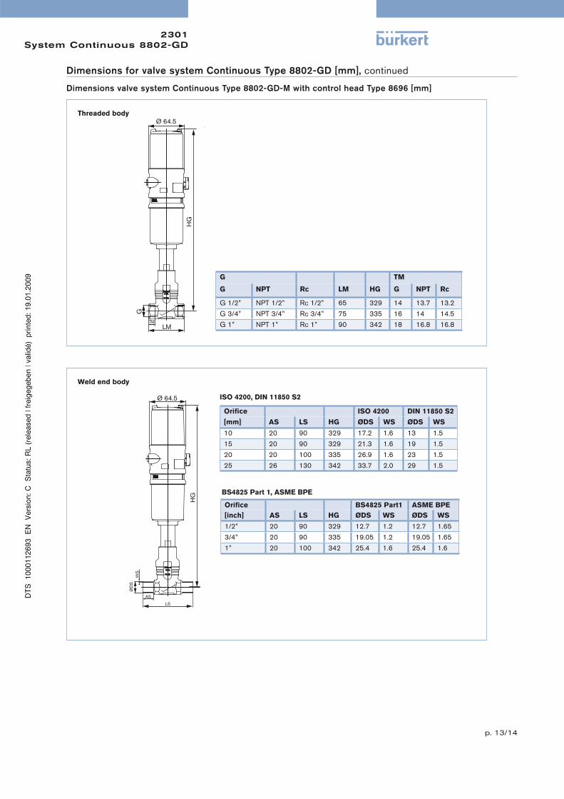
Dimensions for valve system Continuous Type 8802-GD [mm], continued
Dimensions valve system Continuous Type 8802-GD-M with control head Type 8696 [mm]
p. 13/14
2301System Continuous 8802-GD
Threaded body
Weld end body
ISO 4200, DIN 11850 S2
BS4825 Part 1, ASME BPE
G TM
G NPT Rc LM HG G NPT Rc
G 1/2” NPT 1/2” Rc 1/2” 65 329 14 13.7 13.2
G 3/4” NPT 3/4” Rc 3/4” 75 335 16 14 14.5
G 1” NPT 1” Rc 1” 90 342 18 16.8 16.8
Orifi ce ISO 4200 DIN 11850 S2
[mm] AS LS HG ØDS WS ØDS WS
10 20 90 329 17.2 1.6 13 1.5
15 20 90 329 21.3 1.6 19 1.5
20 20 100 335 26.9 1.6 23 1.5
25 26 130 342 33.7 2.0 29 1.5
Orifi ce BS4825 Part1 ASME BPE
[inch] AS LS HG ØDS WS ØDS WS
1/2” 20 90 329 12.7 1.2 12.7 1.65
3/4” 20 90 335 19.05 1.2 19.05 1.65
1” 20 100 342 25.4 1.6 25.4 1.6
Dimensions for valve system Continuous Type 8802-GD [mm], continued
Dimensions valve system Continuous Type 8802-GD-M with control head Type 8696 [mm]
p. 14/14
2301System Continuous 8802-GD
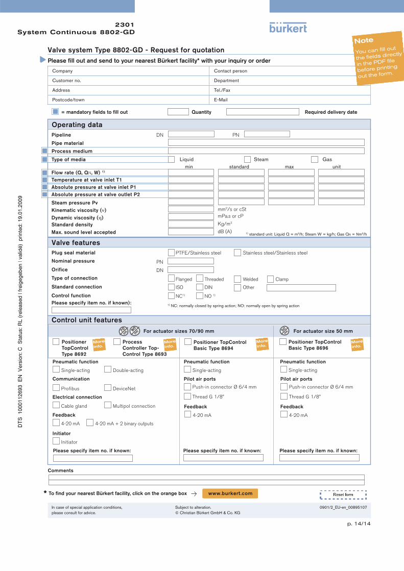
Operating data
= mandatory fi elds to fi ll out Quantity Required delivery date
Pipeline
Process medium
Type of media Liquid Steam Gas
Valve features
DN PN
Company Contact person
Customer no. Department
Address Tel./Fax
Postcode/town E-Mail
Valve system Type 8802-GD - Request for quotation
Please fi ll out and send to your nearest Bürkert facility* with your inquiry or order
Nominal pressure PN
Orifice DN
Flanged Threaded Welded ClampType of connection
ISO DIN OtherStandard connection
NC1) NO 1)Control function
1) NC: normally closed by spring action; NO: normally open by spring action
Pipe material
Note
You can fill out
the fields directly
in the PDF file
before printing
out the form.
In case of special application conditions,
please consult for advice.
Subject to alteration.
© Christian Bürkert GmbH & Co. KG
0901/2_EU-en_00895107
Please specify item no. if known):
To fi nd your nearest Bürkert facility, click on the orange box www.burkert .com*
Comments
Control unit features
Positioner
TopControl
Type 8692
Process
Controller Top-
Control Type 8693
For actuator sizes 70/90 mm For actuator size 50 mm
Positioner TopControl
Basic Type 8694
Positioner TopControl
Basic Type 8696
Pneumatic function
Single-acting Double-acting
Communication
Pneumatic function Pneumatic function
Single-acting
Please specify item no. if known: Please specify item no. if known: Please specify item no. if known:
Single-acting
Electrical connection
Profibus DeviceNet
Cable gland Multipol connection
Feedback
Feedback Feedback
Initiator
4-20 mA 4-20 mA + 2 binary outputs
4-20 mA 4-20 mA
Initiator
Pilot air portsPilot air ports
Push-in connector Ø 6/4 mm
Thread G 1/8”
Push-in connector Ø 6/4 mm
Thread G 1/8”
PTFE/Stainless steel Stainless steel/Stainless steelPlug seal material
Temperature at valve inlet T1
Standard density
Max. sound level accepted
min standard max unitFlow rate (Q, QN, W) 1)
Absolute pressure at valve inlet P1
Absolute pressure at valve outlet P2
Steam pressure Pv
Kinematic viscosity (ν)
Dynamic viscosity (η)
mm2/s or cSt
mPa.s or cP
Kg/m3
dB (A) 1) standard unit: Liquid Q = m3/h; Steam W = kg/h; Gas QN = Nm3/h