2/2 way Directional Control Valves, type VDH -...
23
07-2009 DKCFN.PD.042.G1.02 521B0613 Data sheet 2/2 way Directional Control Valves, type VDH For inline mounting and Cetop 3 flange mounting (ISO 4401) Inline versions: • VDH 30 E 2/2, • VDH 60 E 2/2, • VDH 120 E 2/2 Cetop 3 block version: • VDH 30 EC 2/2 Directional valves are used to control water flow direction. The valves are designed for tap water, i.e. without additives (EU-Directive 98/83/EC). Application Function Advantages Variants Filtration The directional valves are pilot operated On/Off 2/2-way seat valves electrically activated by 1 coil. • Corrosion resistant surfaces • Easy to clean surfaces • The seat valve design ensures zero leakage • High degree of protection, IP 67 • Cetop valve installable on all cetop 3 blocks The valve housing comes in standard version in stainless steel AISI 304 (W. nr. 1.4301). The valve is available as a normally closed valve (NC) or as a normally open valve (NO). On request the valve housing is obtainable in stainless steel AISI 316 L (W. nr. 1.4401), please contact the Danfoss Sales Organization for Water Hydraulics. The water supplied to the valve must be filtered: 10 μm absolute, β 10 -value > 5000 filter is recommended. For further information on filters, please contact the Danfoss sales department for water hydraulics.
Transcript of 2/2 way Directional Control Valves, type VDH -...

07-2009 DKCFN.PD.042.G1.02 521B0613
Data sheet
2/2 way Directional Control Valves, type VDHFor inline mounting and Cetop 3 fl ange mounting (ISO 4401)
Inline versions:
• VDH 30 E 2/2, • VDH 60 E 2/2, • VDH 120 E 2/2
Cetop 3 block version:
• VDH 30 EC 2/2
Directional valves are used to control water fl ow direction.
The valves are designed for tap water, i.e. without additives (EU-Directive 98/83/EC).
Application
Function
Advantages
Variants
Filtration
The directional valves are pilot operated On/Off 2/2-way seat valves electrically activated by 1 coil.
• Corrosion resistant surfaces• Easy to clean surfaces• The seat valve design ensures zero leakage
• High degree of protection, IP 67• Cetop valve installable on all cetop 3 blocks
The valve housing comes in standard version in stainless steel AISI 304 (W. nr. 1.4301). The valve is available as a normally closed valve (NC) or as a normally open valve (NO).
On request the valve housing is obtainable in stainless steel AISI 316 L (W. nr. 1.4401), please contact the Danfoss Sales Organization for Water Hydraulics.
The water supplied to the valve must be fi ltered: 10 μm absolute, β10-value > 5000 fi lter is recommended.
For further information on fi lters, please contact the Danfoss sales department for water hydraulics.
2 DKCFN.PD.042.G1.02 521B0613
Data Sheet 2/2 way Directional Control Valves, type VDH
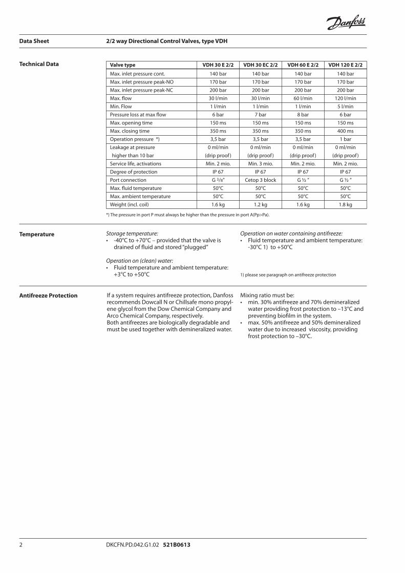
Technical Data
Temperature
Antifreeze Protection If a system requires antifreeze protection, Danfoss recommends Dowcall N or Chillsafe mono propyl-ene glycol from the Dow Chemical Company and Arco Chemical Company, respectively. Both antifreezes are biologically degradable and must be used together with demineralized water.
Mixing ratio must be:• min. 30% antifreeze and 70% demineralized
water providing frost protection to –13°C and preventing biofi lm in the system.
• max. 50% antifreeze and 50% demineralized water due to increased viscosity, providing frost protection to –30°C.
Valve type VDH 30 E 2/2 VDH 30 EC 2/2 VDH 60 E 2/2 VDH 120 E 2/2
Max. inlet pressure cont. 140 bar 140 bar 140 bar 140 barMax. inlet pressure peak-NO 170 bar 170 bar 170 bar 170 barMax. inlet pressure peak-NC 200 bar 200 bar 200 bar 200 barMax. fl ow 30 l/min 30 l/min 60 l/min 120 l/minMin. Flow 1 l/min 1 l/min 1 l/min 5 l/minPressure loss at max fl ow 6 bar 7 bar 8 bar 6 barMax. opening time 150 ms 150 ms 150 ms 150 msMax. closing time 350 ms 350 ms 350 ms 400 msOperation pressure *) 3,5 bar 3,5 bar 3,5 bar 1 barLeakage at pressure 0 ml/min 0 ml/min 0 ml/min 0 ml/min higher than 10 bar (drip proof ) (drip proof ) (drip proof ) (drip proof )Service life, activations Min. 2 mio. Min. 3 mio. Min. 2 mio. Min. 2 mio. Degree of protection IP 67 IP 67 IP 67 IP 67Port connection G 3/8” Cetop 3 block G ½ ” G ½ ”Max. fl uid temperature 50°C 50°C 50°C 50°CMax. ambient temperature 50°C 50°C 50°C 50°CWeight (incl. coil) 1.6 kg 1.2 kg 1.6 kg 1.8 kg
*) The pressure in port P must always be higher than the pressure in port A(Pp>Pa).
Storage temperature: • -40°C to +70°C – provided that the valve is
drained of fl uid and stored “plugged”
Operation on (clean) water: • Fluid temperature and ambient temperature:
+3°C to +50°C
Operation on water containing antifreeze:• Fluid temperature and ambient temperature:
-30°C 1) to +50°C
1) please see paragraph on antifreeze protection

DKCFN.PD.042.G1.02 521B0613 3
Data Sheet 2/2 way Directional Control Valves, type VDH
Code Numbers Valves (without coil) Steel type Port connection Function symbol Code number
VDH 30 E 2/2 NC AISI 304 G 3/8” 180L0002
VDH 30 E 2/2 NO AISI 304 G 3/8” 180L0003
VDH 60 E 2/2 NC AISI 304 G 1/2” 180L0011
VDH 60 E 2/2 NO AISI 304 G 1/2” 180L0015
VDH 120 E 2/2 NC AISI 304 G 1/2” 180L0001
VDH 120 E 2/2 NO AISI 304 G 1/2” 180L0005
VDH 30 EC 2/2 NC AISI 304 Cetop 3 180L0048
VDH 30 EC 2/2 NO AISI 304 Cetop 3 180L0049
The valves are supplied without coils which must be ordered separately. VDH 30EC 2/2 way valves are supplied with screws and O-rings.
Cetop 3 blocks Steel type Weight Code number
Block for 1 cetop valve AISI 304 1.0 kg 180L0061Block for 2 cetop valves AISI 304 1.8 kg 180L0062Block for 3 cetop valves AISI 304 2.6 kg 180L0063Block for 4 cetop valves AISI 304 3.4 kg 180L0064
Coil
New coils
(clip-on)
(NC + NO)
24 V / 50 Hz /10 W 018F7920
220 V / 50 Hz /10 W 018F7921
240 V / 50 Hz /10 W 018F7924
24 V / 60 Hz /10 W 018F7922
220 V / 60 Hz /10 W 018F7925
240 V / 60 Hz /10 W 018F7926
110 V / 50/60 Hz /10 W 018F7923
12 V d.c. / 18 W 018F7913
24 V d.c. / 18 W 018F7914
ATEX - consult the document "solenoid valves intended for use in ATEX classifi ed areas" 521B1101
4 DKCFN.PD.042.G1.02 521B0613
Data Sheet 2/2 way Directional Control Valves, type VDH
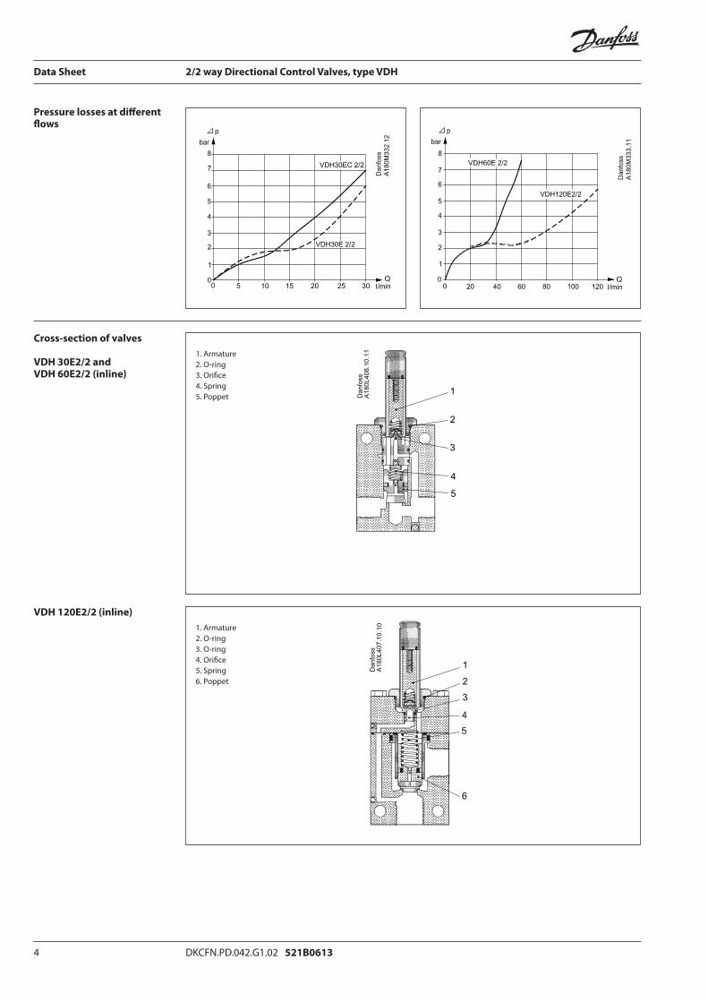
Pressure losses at diff erent fl ows
Cross-section of valves
VDH 30E2/2 and VDH 60E2/2 (inline)
VDH 120E2/2 (inline)
1. Armature2. O-ring3. Orifi ce4. Spring5. Poppet
1. Armature2. O-ring3. O-ring4. Orifi ce5. Spring6. Poppet
DKCFN.PD.042.G1.02 521B0613 5
Data Sheet 2/2 way Directional Control Valves, type VDH
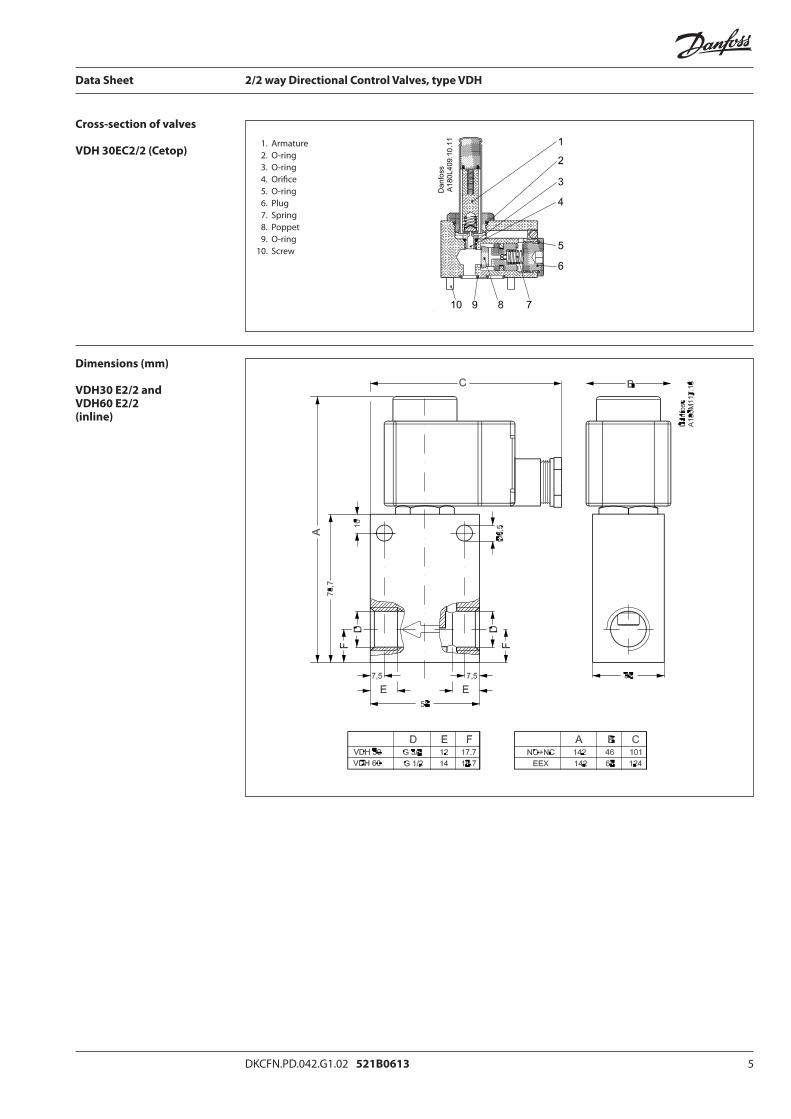
Cross-section of valves
VDH 30EC2/2 (Cetop)
Dimensions (mm)
VDH30 E2/2 and VDH60 E2/2 (inline)
1. Armature 2. O-ring 3. O-ring 4. Orifi ce 5. O-ring 6. Plug 7. Spring 8. Poppet 9. O-ring 10. Screw
6 DKCFN.PD.042.G1.02 521B0613
Data Sheet 2/2 way Directional Control Valves, type VDH
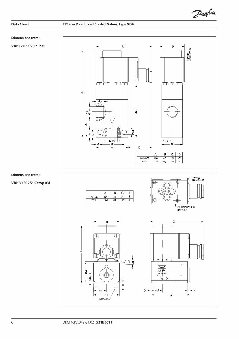
Dimensions (mm)
VDH120 E2/2 (inline)
Dimensions (mm)
VDH30 EC2/2 (Cetop 03)

DKCFN.PD.042.G1.02 521B0613 7
Data Sheet 2/2 way Directional Control Valves, type VDH
Dimensions (mm)
Cetop blocks
Mounting of inline valves
Mounting of valve on Cetop block
Mounting of coil on valve
Inline valves are mounted in line in fl ow direction (follow the arrow on the valve) and fi xed either
directly in the pipe connections or with bolts in the fi xation holes on the valve.
The valve is designed to be mounted on a block with CETOP 3-port connection. Four stainless steel screws and four O-rings are supplied with the valve for mounting. Remember to smear/
spray the threads on the screws with Molykote® D pasta from Dow Corning, or Klüber UH1 84-201 from Klüber lubrication, before mounting the valve.
Block for 1 valveBlock for 2 valvesBlock for 3 valvesBlock for 4 valves
Coil on valves with short armature tubes (NC and NO valves)1. Place the o-ring on the armature tube.2. The coil is clicked on by means of a light
pressure by hand – without using tools.
8 DKCFN.PD.042.E9.02 521B0613
Data Sheet 2/2 way Directional Control Valves, type VDH
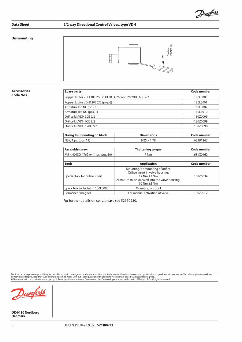
Dismounting
Accessories Code Nos.
Spare parts Code number
Poppet kit for VDH 30E 2/2, VDH 30 EC2/2 and 2/2 VDH 60E 2/2 180L5005
Poppet kit for VDH120E 2/2 (pos. 6) 180L5001Armature kit, NC (pos. 1) 180L5002Armature kit, NO (pos. 1) 180L5010Orifi ce kit VDH 30E 2/2 180Z0099Orifi ce kit VDH 60E 2/2 180Z0099Orifi ce kit VDH 120E 2/2 180Z0098
O-ring for mounting on block Dimensions Code number
NBR, 1 pc. (pos. 11) 9.25 × 1.78 633B1243
Assembly screw Tightening torque Code number
M5 × 40 ISO 4762 A4, 1 pc (pos. 10) 7 Nm 681X0162
Tools Application Code number
Special tool for orifi ce insert
Mounting/dismounting of orifi ceOrifi ce insert in valve housing:
12 Nm ±2 NmArmature to be screwed into the valve housing:
60 Nm ±2 Nm
180Z0034
Spool tool included in 180L5005 Mounting of spoolPermanent magnet For manual activation of valve 180Z0212
For further details on coils, please see 521B0980.

07-2009 DKCFN.PD.042.N6.02 521B0605
Data sheet
Directional Control Valve type VDH 30EC 4/3For Cetop 3 fl ange mounting (ISO 4401) and inline mounting
Directional valves are used to control the direction of water fl ow.
The valves are designed for tap water, i.e. without additives. (EU-Directive 98/83/EC).
The directional valves are pilot operated On/Off seat valves electrically activated by 4 coils. The valves are designed according to the seat valve principle where each individual seat valve is controlled by its own pilot stage.
This valve type contains 4 seat valves altogether: two inlet valves and two outlet valves. As each seat valve is individually controlled by its own pilot, this design off ers many diff erent valve confi gurations to the end user.
Applications
Function
Advantages
Variants
Filtration
• Installable on all Cetop 3 blocks and inline blocks
• Corrosion resistant surfaces• Easy-to-clean surfaces
• The seat valve design ensures minimum leak-age
• High degree of enclosure, IP67• Many valve confi gurations available
The valve housing comes in standard version in stainless steel AISI 304 (W. No. 1.4301) or AISI 316 (W. No. 1.4401).
The valve is available as a Normally Closed valve (NC) or in a combination of Normally Open (NO) and Normally Closed (NC).
The water supply must be fi ltered through a 10 μm abs., β10-value > 5000 fi lter.
For further fi lter details, please contact the Danfoss Sales Organization.

2 DKCFN.PD.042.N6.02 521B0605
Data sheet Directional control valve type VDH 30EC 4/3
Technical data
Temperature
Antifreeze Protection
Code numbers
If a system requires antifreeze protection, Danfoss recommends Dowcall N or Chillsafe mono propyl-ene glycol from the Dow Chemical Company and Arco Chemical Company, respectively. Both antifreezes are biologically degradable and must be used together with demineralized water.
Mixing ratio must be:• min. 30% antifreeze and 70% demine- ralized water providing frost protection to
–13°C and preventing biofi lm in the system. • max. 50% antifreeze and 50% demine- ralized water due to increased viscosity, providing frost protection to –30°C.
Max. pressure port P, A and B *) 140 bar
Return pressure, port T (T ≤ A, B pressure) *) 140 barMin. inlet pressure 5 barMax fl ow 30 l/minMin. fl ow 1 l/minPressure loss See curve page 3Opening time when changing direction **) 110 msClosing time when changing direction **) 130 msLeakage, port P → A, B, T 0 ml/minLeakage, port A, B → T 0 ml/minLeakage, port, A, B → P (inlet pressure port P = 0 bar) max 5 ml/minLeakage, port A, B → P (inlet pressure port P = pressure port A, B) 0 ml/minService life 7 million activationsDegree of enclosure IP 67
*) The pressure in each of the ports P, A and B must always be higher than the pressure in port T**) No electrical delay required when changing direction
Storage temperature: • -40°C to +70°C – provided that the valve is
drained of fl uid and stored ”plugged”
Operation on (clean) water: • Fluid temperature and ambient temperature:
+3°C to +50°C
Operation on water containing antifreeze:• Fluid temperature and ambient temperature:
-30°C 1) to +50°C
1) please see paragraph on antifreeze protection
Valves (without coils) Function symbol Weight Code
kg number
VDH 30 EC - NC 3.8 180L0046
stainless steel, AISI 304
VDH 30 EC - NC 3,8 180L0047
stainless steel, AISI 316
VDH 30 EC - 2xNC +2xNO
3,8 180L0050stainless steel, AISI 304
Electrical: 12 V d.c., 24 V d.c., 24 V a.c., 110 V a.c. , 240 V a.c.Activation of valve Power consumption: 18 W (d.c.), 10 W (a.c.) per coil Manual with permanent magnet
DKCFN.PD.042.N6.02 521B0605 3
Data sheet Directional control valve type VDH 30EC 4/3
Cetop 3 blocks and cover plate Weight Code
kg number
Inline block for 1 valve (P&T direct for VPH15E) 0.8 180L0060Inline block for 1 valve (A&B same position as 180L0053) 0.8 180L0080Block for 1 valve 2.4 180L0081Block for 2 valves 4.4 180L0082Block for 3 valves 7.3 180L0083Block for 4 valves 9.6 180L0084Block for 5 valves 12.1 180L0085
Cover plate*) (for covering-up non-used valve outlets on block) 0.1 180L0079*) Supplied with screws and O-rings
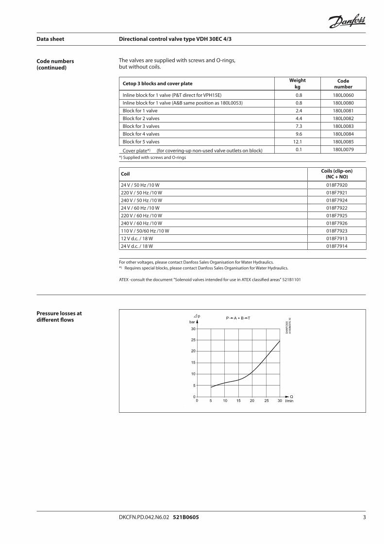
Code numbers(continued)
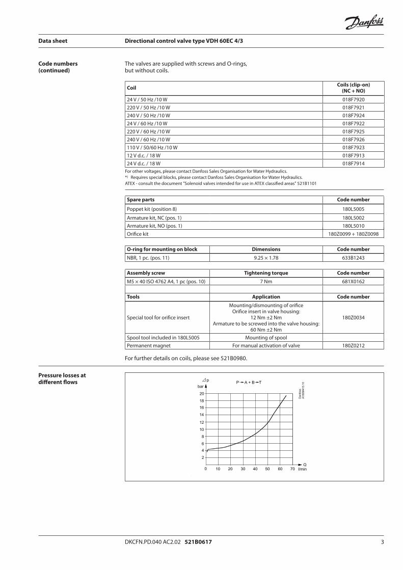
Pressure losses at diff erent fl ows
The valves are supplied with screws and O-rings, but without coils.
CoilCoils (clip-on)
(NC + NO)
24 V / 50 Hz /10 W 018F7920220 V / 50 Hz /10 W 018F7921240 V / 50 Hz /10 W 018F792424 V / 60 Hz /10 W 018F7922220 V / 60 Hz /10 W 018F7925240 V / 60 Hz /10 W 018F7926110 V / 50/60 Hz /10 W 018F792312 V d.c. / 18 W 018F791324 V d.c. / 18 W 018F7914
For other voltages, please contact Danfoss Sales Organisation for Water Hydraulics.*) Requires special blocks, please contact Danfoss Sales Organisation for Water Hydraulics.
ATEX -consult the document "Solenoid valves intended for use in ATEX classifi ed areas" 521B1101
4 DKCFN.PD.042.N6.02 521B0605
Data sheet Directional control valve type VDH 30EC 4/3
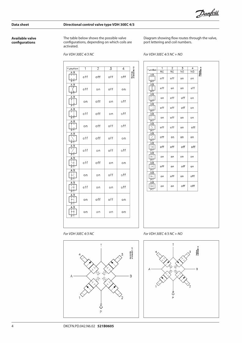
Available valve confi gurations
The table below shows the possible valve confi gurations, depending on which coils are activated.
For VDH 30EC 4/3 NC
For VDH 30EC 4/3 NC
Diagram showing fl ow routes through the valve, port lettering and coil numbers.
For VDH 30EC 4/3 NC + NO
For VDH 30EC 4/3 NC + NO
DKCFN.PD.042.N6.02 521B0605 5
Data sheet Directional control valve type VDH 30EC 4/3
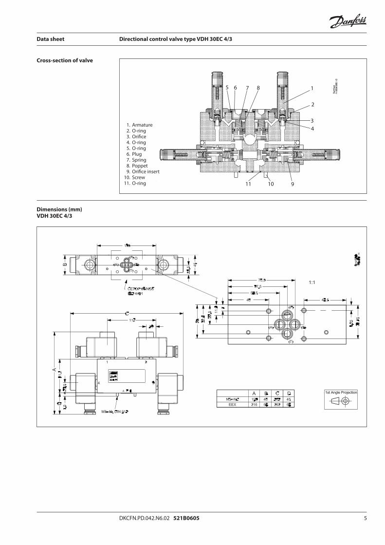
Cross-section of valve
Dimensions (mm)VDH 30EC 4/3
1. Armature 2. O-ring 3. Orifi ce 4. O-ring 5. O-ring 6. Plug 7. Spring 8. Poppet 9. Orifi ce insert 10. Screw 11. O-ring
5 6 7 8 1
2
34
91011
6 DKCFN.PD.042.N6.02 521B0605
Data sheet Directional control valve type VDH 30EC 4/3
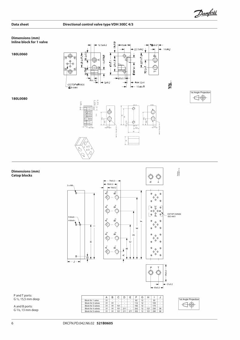
Dimensions (mm)Inline block for 1 valve
180L0060
180L0080
Dimensions (mm)Cetop blocks
P and T ports:G ½, 15,5 mm deep
A and B ports: G 3/8, 13 mm deep
DKCFN.PD.042.N6.02 521B0605 7
Data sheet Directional control valve type VDH 30EC 4/3
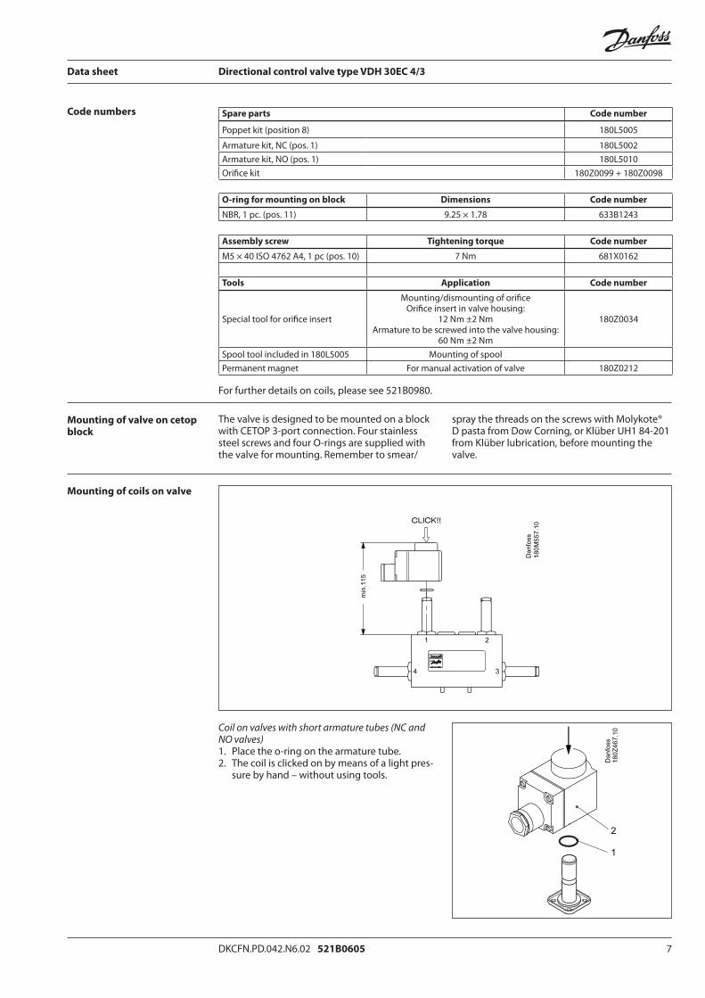
Code numbers
Mounting of valve on cetop block
Mounting of coils on valve
The valve is designed to be mounted on a block with CETOP 3-port connection. Four stainless steel screws and four O-rings are supplied with the valve for mounting. Remember to smear/
spray the threads on the screws with Molykote® D pasta from Dow Corning, or Klüber UH1 84-201 from Klüber lubrication, before mounting the valve.
Coil on valves with short armature tubes (NC and NO valves)1. Place the o-ring on the armature tube.2. The coil is clicked on by means of a light pres-
sure by hand – without using tools.
Spare parts Code number
Poppet kit (position 8) 180L5005
Armature kit, NC (pos. 1) 180L5002Armature kit, NO (pos. 1) 180L5010Orifi ce kit 180Z0099 + 180Z0098
O-ring for mounting on block Dimensions Code number
NBR, 1 pc. (pos. 11) 9.25 × 1.78 633B1243
Assembly screw Tightening torque Code number
M5 × 40 ISO 4762 A4, 1 pc (pos. 10) 7 Nm 681X0162
Tools Application Code number
Special tool for orifi ce insert
Mounting/dismounting of orifi ceOrifi ce insert in valve housing:
12 Nm ±2 NmArmature to be screwed into the valve housing:
60 Nm ±2 Nm
180Z0034
Spool tool included in 180L5005 Mounting of spoolPermanent magnet For manual activation of valve 180Z0212
For further details on coils, please see 521B0980.
8 DKCFN.PD.042.N6.02 521B0605
Data sheet Directional control valve type VDH 30EC 4/3
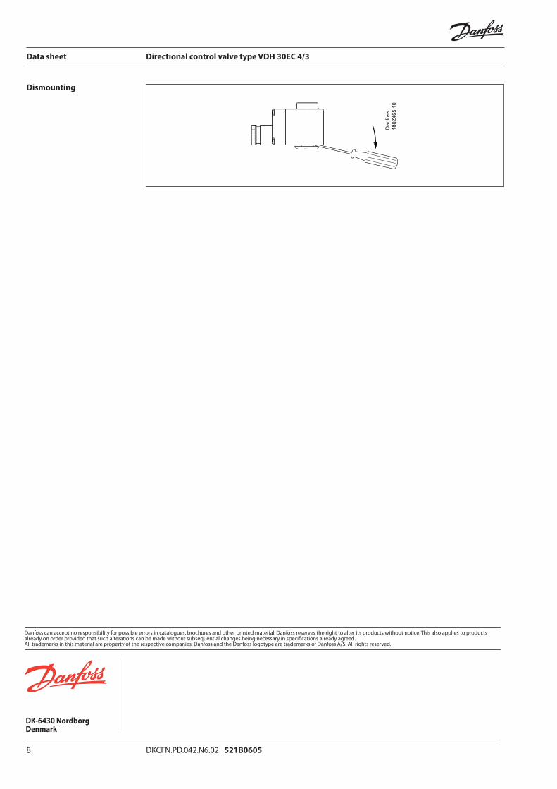
Dismounting

07-2009 DKCFN.PD.042 AC4.02 521B0617
Data Sheet
Directional Control Valve type VDH 60EC 4/3For Cetop 5 fl ange mounting (ISO 4401) and inline mounting
Directional valves are used to control the direction of water fl ow.The valves are designed for tap water, i.e. without additives. (EU-Directive 98/83/EC).
The directional valves are pilot operated On/Off seat valves electrically activated by 4 coils. The valves are designed according to the seat valve principle where each individual seat valve is controlled by its own pilot stage.
This valve type contains 4 seat valves altogether: two inlet valves and two outlet valves. As each seat valve is individually controlled by its own pilot, this design off ers many diff erent valve confi gurations to the end user.
Applications
Function
Advantages
Variants
Filtration
• Installable on all Cetop 5 blocks and inline blocks
• Corrosion resistant materials• Easy-to-clean surfaces
• The seat valve design ensures minimum leakage
• High degree of enclosure, IP 67• Many valve confi gurations available
The valve housing comes in the standard version in stainless steel AISI 304 or AISI 316.
The valve is available as a Normally Closed valve (NC) or in a combination of Normally Open (NO) and Normally Closed (NC).
The water supply must be fi ltered through a 10 μm abs., ß10-value > 5000 fi lter.
For further fi lter details, please contact the Danfoss Sales Organization.

2 DKCFN.PD.042.AC4.02 521B0617
Data sheet Directional control valve type VDH 60EC 4/3
Technical data
Temperature
Antifreeze Protection
Code numbers
If a system requires antifreeze protection, Danfoss recommends Dowcall N or Chillsafe mono propyl-ene glycol from the Dow Chemical Company and Arco Chemical Company, respectively. Both antifreezes are biologically degradable and must be used together with demineralized water. Mixing ratio must be:
• min. 30% antifreeze and 70% demineralized water providing frost protection to –13°C and preventing biofi lm in the system.
• max. 50% antifreeze and 50% demineralized water due to increased viscosity, providing frost protection to –30°C.
Max. pressure port P, A and B *) 140 bar
Return pressure, port T (T ≤ A, B pressure) *) 140 barMin. inlet pressure 5 barMax fl ow 60 l/minMin. fl ow 1 l/minPressure loss See curve page 3Opening time when changing direction **) 110 msClosing time when changing direction **) 130 msLeakage, port P → A, B, T 0 ml/minLeakage, port A, B → T 0 ml/minLeakage, port, A, B → P (inlet pressure port P = 0 bar) max 5 ml/minLeakage, port A, B → P (inlet pressure port P = pressure port A, B) 0 ml/minService life 7 million activationsDegree of enclosure IP 67
*) The pressure in each of the ports P, A and B must always be higher than the pressure in port T**) No electrical delay required when changing direction
Storage temperature: • -40°C to +70°C – provided that the valve is
drained of fl uid and stored with the ports ”plugged”
Operation on (clean) water: • Fluid temperature and ambient temperature:
+3°C to +50°C
Operation on water containing antifreeze:• Fluid temperature and ambient temperature:
–30°C 1) to +50°C
1) please see paragraph on antifreeze protection
Valves (without coils) Function symbol Weight Code
kg number
VDH 60 EC - NC 3.8 180L0057
stainless steel, AISI 304
VDH 60 EC - NC 3,8 180L0058
stainless steel, AISI 316
VDH 60 EC - 2xNC +2xNO
3,8 stainless steel, AISI 304
Electrical: 12 V d.c., 24 V d.c., 24 V a.c., 110 V a.c. , 240 V a.c.Activation of valve Power consumption: 18 W (d.c.), 10 W (a.c.) per coil Manual with permanent magnet
180L0059
DKCFN.PD.040 AC2.02 521B0617 3
Data sheet Directional control valve type VDH 60EC 4/3
Code numbers(continued)
Pressure losses at diff erent fl ows
The valves are supplied with screws and O-rings, but without coils.
CoilCoils (clip-on)
(NC + NO)
24 V / 50 Hz /10 W 018F7920220 V / 50 Hz /10 W 018F7921240 V / 50 Hz /10 W 018F792424 V / 60 Hz /10 W 018F7922220 V / 60 Hz /10 W 018F7925240 V / 60 Hz /10 W 018F7926110 V / 50/60 Hz /10 W 018F792312 V d.c. / 18 W 018F791324 V d.c. / 18 W 018F7914
For other voltages, please contact Danfoss Sales Organisation for Water Hydraulics.*) Requires special blocks, please contact Danfoss Sales Organisation for Water Hydraulics.ATEX - consult the document "Solenoid valves intended for use in ATEX classifi ed areas" 521B1101
Spare parts Code number
Poppet kit (position 8) 180L5005
Armature kit, NC (pos. 1) 180L5002Armature kit, NO (pos. 1) 180L5010Orifi ce kit 180Z0099 + 180Z0098
O-ring for mounting on block Dimensions Code number
NBR, 1 pc. (pos. 11) 9.25 × 1.78 633B1243
Assembly screw Tightening torque Code number
M5 × 40 ISO 4762 A4, 1 pc (pos. 10) 7 Nm 681X0162
Tools Application Code number
Special tool for orifi ce insert
Mounting/dismounting of orifi ceOrifi ce insert in valve housing:
12 Nm ±2 NmArmature to be screwed into the valve housing:
60 Nm ±2 Nm
180Z0034
Spool tool included in 180L5005 Mounting of spoolPermanent magnet For manual activation of valve 180Z0212
For further details on coils, please see 521B0980.
4 DKCFN.PD.042.AC4.02 521B0617
Data sheet Directional control valve type VDH 60EC 4/3
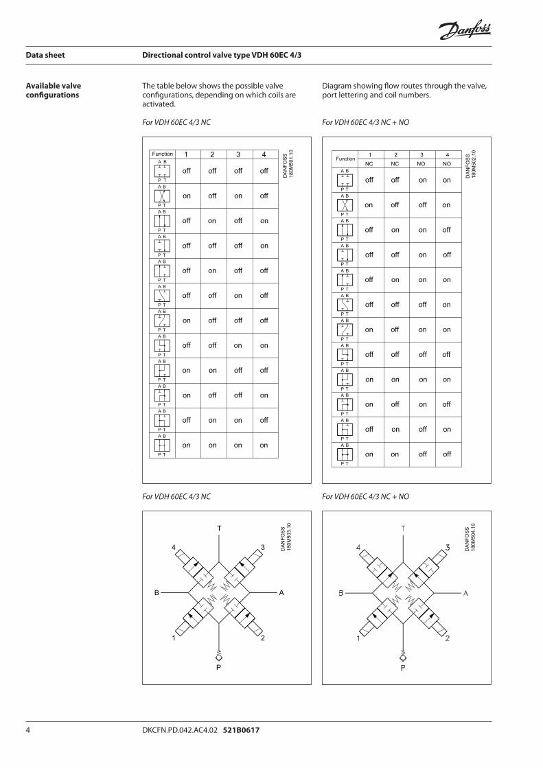
The table below shows the possible valve confi gurations, depending on which coils are activated.
For VDH 60EC 4/3 NC
For VDH 60EC 4/3 NC
Diagram showing fl ow routes through the valve, port lettering and coil numbers.
For VDH 60EC 4/3 NC + NO
For VDH 60EC 4/3 NC + NO
Available valve confi gurations
DKCFN.PD.040 AC2.02 521B0617 5
Data sheet Directional control valve type VDH 60EC 4/3
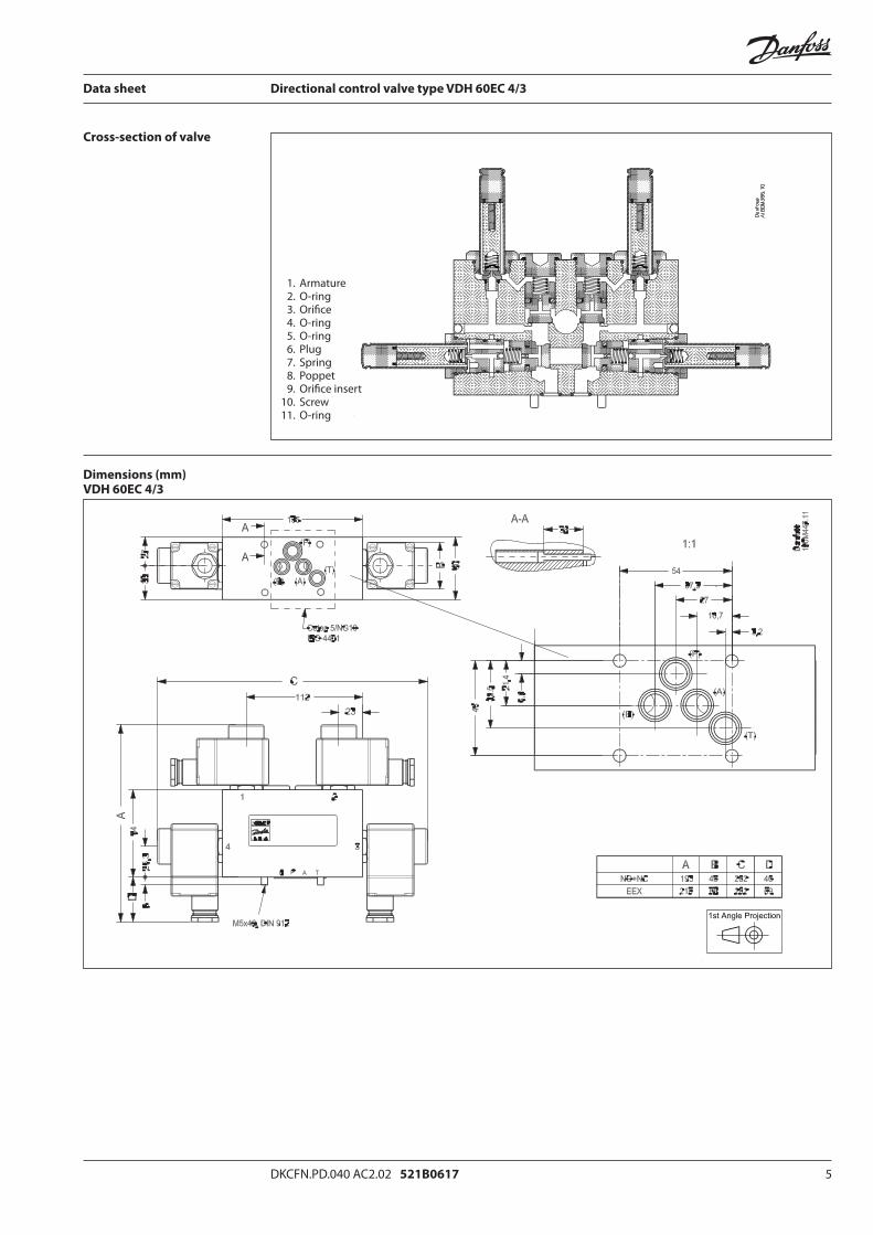
Cross-section of valve
Dimensions (mm)VDH 60EC 4/3
1. Armature 2. O-ring 3. Orifi ce 4. O-ring 5. O-ring 6. Plug 7. Spring 8. Poppet 9. Orifi ce insert 10. Screw 11. O-ring
6 DKCFN.PD.042.AC4.02 521B0617
Data sheet Directional control valve type VDH 60EC 4/3
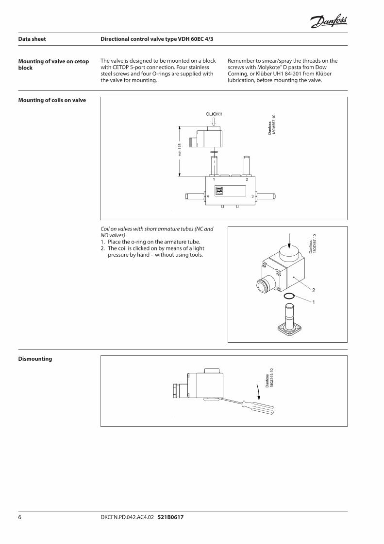
Mounting of valve on cetop block
Mounting of coils on valve
Dismounting
The valve is designed to be mounted on a block with CETOP 5-port connection. Four stainless steel screws and four O-rings are supplied with the valve for mounting.
Remember to smear/spray the threads on the screws with Molykote® D pasta from Dow Corning, or Klüber UH1 84-201 from Klüber lubrication, before mounting the valve.
Coil on valves with short armature tubes (NC and NO valves)1. Place the o-ring on the armature tube.2. The coil is clicked on by means of a light
pressure by hand – without using tools.
7 DKCFN.PD.042.AC4.02 521B0617
Data sheet Directional control valve type VDH 60EC 4/3


![Lecture 16 DIRECTIONAL CONTROL VALVE [CONTINUED] 2/Lecture 16.pdf · Lecture 16 DIRECTIONAL CONTROL VALVE [CONTINUED] 1.7.1 2/2-Way DCV (Normally Closed) Figure 1.7shows a two-way](https://static.fdocuments.us/doc/165x107/5b5ad0cf7f8b9a01748cb5d1/lecture-16-directional-control-valve-continued-2lecture-16pdf-lecture-16.jpg)