22-Leica Laser Tracker and 6DoF measurements strtegies in ... · 1 Laser Tracker and 6DoF...
20
1 Laser Tracker and 6DoF measurement strategies in industrial robot applications Dr. Raimund Loser CMSC Conference July 25 th -29 th 2011 Phoenix Arizona
Transcript of 22-Leica Laser Tracker and 6DoF measurements strtegies in ... · 1 Laser Tracker and 6DoF...

1
Laser Tracker and 6DoF measurement
strategies in industrial robot applications
Dr. Raimund Loser
CMSC Conference
July 25th -29th 2011
Phoenix Arizona

2
Introduction
• Efficiency of industrial robot applications are dependent on multiple
influences
• Components of the application have to be analyzed separately
• Adjustment of single influences result in evident accuracy increases
>> Even with adjusted components there is still a gap between
theoretical (simulated) and practical world

3
Introduction
• Dedicated measurement strategies for identification or calibration of
application components
• Improvement of resulting accuracy by integration of 3D and 6DoF
measurement results for correction
• Various possibilities to use laser tracker systems to compensate
static or dynamic influences
4
In this presentation
• How to identify system inaccuracies?
• What are influences on application accuracy?
• Which parts can be measured / calibrated / corrected using laser
tracker?
• How can the influences be avoided / reduced to a minimum?
• Is it possible to get rid of all component influences ?

5
Analyzing industrial robots
• Robot accuracy depending on time-variant influences
• Every robot is different due to manufacturing tolerances
• Offline programmed robot movement positions never fit to reality
• Robot model selection for dedicated application tasks is depending
on robot accuracy
• Identification of peripheral geometries help to increase the accuracy
of the system

6
Analyzing industrial robots
• Identification of robot base frame by
laser tracker measurement
• 6-dimensional measurements for
exact tool center point detection
• Check of robot static positional
accuracy via residual vectors of
best-fit transformation

7
Analyzing industrial robots
• Determination of robot static &
dynamic accuracy via DIN EN ISO
9283
• Evaluation process for customer
• Dynamic 6-dof measurements with
a rate of up to 1 kHz
• Path motion behavior analysis even with high movement speed
8
Linear Tracks
• Used for increasing the robots working range
• 2m to up to 30m for long range application e.g. in aircraft of windcraft
industry
• Linear tracks are influencing application accuracy additional to the
robot
• Adjusted during the mounting process, robot weight and movement
influence is not considered
• Dynamic robot movement on skid causes forces and torques

9
Linear Tracks
Common techniques:
• Simple two-point
measurements for
gear factor
identification
• Track direction identification in robot coordinate system (alignment)
Laser Tracker method:
• Non-linearity of the track identified by 6-dof measurement
10
Linear Tracks
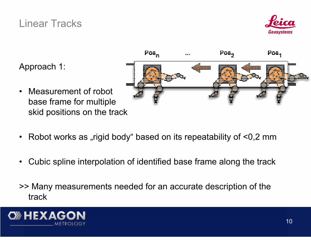
Approach 1:
• Measurement of robot
base frame for multiple
skid positions on the track
• Robot works as „rigid body“ based on its repeatability of <0,2 mm
• Cubic spline interpolation of identified base frame along the track
>> Many measurements needed for an accurate description of the
track
11
Approach 2:
• 6-dof continuous measurement scan of the linear track skid
• Exact geometrical description of track profile via fine scan
• Positional correction of robot in 6 dimensions for arbitrary skid
positions
>> Easy measurement procedure
Linear Tracks

12
• Robot program construction off-line
using CAD simulation tools
• Generation for one robot, mirroring
on symmetrical work pieces
• Copying of programs to parallel
working cells
>> Integration of acquired measurement results into copy & mirror
process to keep the needed accuracy
Copy & Mirror of robot programs

13
• Object position identification via vision system
• Multi-camera, laser-line, light-stripe or other methods base on good
calibration
• Determination of sensor positions
or calibration using 6-dof measurement
technology
• Even hidden points e.g. for sensor body
reference measurement possible with
special tip adapters
Vision System calibration
14
Laser tracker as inline measurement system
• Optimal setup of components results in high accuracy for application
• But: Resulting accuracy is still depending on dynamic forces and
non-avoidable influences
>> Always existing gap between theoretical world (CAD) and practical
movement due to limited accuracy
>> Offline-generated programs always have practical deviations
15
Laser tracker as inline measurement system
• Laser tracker not only used for accuracy improvement or calibration
• Over-all pose correction via TCP movement identification
Static correction:
• Integration of laser tracker into working coordinate system
• Measurement of TCP-position in dedicated application positions
• Calculation of 6-dimensional correction offset for each position

16
Laser tracker as inline measurement system
• Offline correction of robot program with processing of movement
results
>> Application of robot with repeating accuracy !
>> 10-times better than positional accuracy !
>> Laser tracker not needed all time in the cell !
>> Correction measurements repeated periodicaly !

17
Dynamic correction:
• Continuous measurement of TCP-position
by laser tracker
• Dynamic correction control loop via real time
interface to robot
• 6D-online correction of robot movement
• Correction of dynamic effects caused by
application forces
>> Complete path motion controlled !
>> Absolute accuracy increased significantly !
Laser tracker as inline measurement system

18
Measure Assisted Production
• Example implementation of correction control loop
• Mixture of static and dynamic correction via iterated movement correction
• „Blind“ movement steps between correction points
• System is easily adaptable to high-speed dynamic correction via real-time interface
• Assembling application as example for robot path guidance

19
• Airplane wing-to-body task
• 6-dimensional measurement of robot tool
• Fixed tool-to-wing transformation
• Calculation of correction values in multiple path positions
• Final blind step for assembling --Link to video--
• Not depending on robot absolute accuracy
Measure Assisted Production
20
Results
• From optimization up to full movement control usage of laser tracker
measurements
• With inline correction control loop all accuracy influences
compensated
• Dynamic robot path motion control with up to 1kHz measurement
rate
• Resulting accuracy ranges:
Absolute static: <0,1 mm
Dynamic: <0,3 mm (depending on speed)


![Toward Compound Navigation Tasks on Mobiles via Spatial ... · peephole using a 6DoF tracker, but does not study it in detail. The Boom Chameleon [8,9,26,27] offers another example](https://static.fdocuments.us/doc/165x107/5f5d7aff104c067ee62cfb49/toward-compound-navigation-tasks-on-mobiles-via-spatial-peephole-using-a-6dof.jpg)