22 February 2013 2013 ASCE Charles Pankow Foundation ... · 2013 ASCE Charles Pankow Foundation...
34
22 February 2013 Team Registration Number: 02-2013 LIGHTING/ELECTRICAL REPORT 2013 ASCE Charles Pankow Foundation Annual Architectural Engineering Student Competition
-
Upload
vuongnguyet -
Category
Documents
-
view
217 -
download
0
Transcript of 22 February 2013 2013 ASCE Charles Pankow Foundation ... · 2013 ASCE Charles Pankow Foundation...

Lighting / Electrical Systems – Team 02-2013 21
22 February 2013
Team Registration Number: 02-2013
LIGHTING/ELECTRICAL REPORT
2013 ASCE Charles Pankow Foundation
Annual Architectural Engineering Student Competition
February 22, 2013
LIGHTING/ ELECTRICAL SUBMISSION
Lighting/Electrical Systems – Team 02-2013 1
Table of Contents 1. Executive Summary .........................................................................................................................2
1.1. Owner Goals ......................................................................................................................3 1.2. Nexus Goals .......................................................................................................................3 1.3. Lighting Goals ....................................................................................................................4
2. Experience .......................................................................................................................................5
2.1 Campus ...............................................................................................................................5 2.2 Lobby ..................................................................................................................................5 2.3 Lobby Rationale ..................................................................................................................6
3. Community ...................................................................................................................................... 6
3.1 Multipurpose Room............................................................................................................ 6 3.2 Multipurpose Room Rationale ........................................................................................... 7 3.3 Pool ..................................................................................................................................... 8 3.4 Pool Rationale ..................................................................................................................... 8
4. Education ......................................................................................................................................10 4.1 Classroom .........................................................................................................................10 4.2 Classroom Rationale .........................................................................................................11
5. Conclusion .....................................................................................................................................12
6. Supporting Documentation ..........................................................................................................13
6.1 Lobby: AGI32 Calculation and Switching Diagram .......................................................... 13 6.2 Multipurpose Room: Emergency Lighting Calculation .................................................... 14 6.3 Multipurpose Room: Switching Diagram ........................................................................ 15 6.4 Pool: AGI32 Calculations ................................................................................................. 16
6.4.1 Daylight Only (Clear Sky)..................................................................................... 16 6.4.2 Combined Electric Lighting and Daylight (Clear Sky) .......................................... 17 6.4.3 Combined Electric Lighting and Daylight (Cloudy) ............................................. 18 6.4.4 Combined with Electric Light at Half-Output (Clear Sky).................................... 19
6.5 Pool: AGI32 Calculation of Emergency Lighting .............................................................. 20 6.6 Pool: Switching/Wiring Diagrams .................................................................................... 21 6.7 Classroom Daylight Analysis ............................................................................................ 22
6.7.1 Noon, Clear Sky ................................................................................................... 22 6.7.2 Noon, Cloudy ...................................................................................................... 23 6.7.3 Morning, Clear Sky .............................................................................................. 24 6.7.4 Morning, Cloudy ................................................................................................. 25 6.7.5 Afternoon, Clear Sky ........................................................................................... 26
6.7.6 Afternoon, Cloudy .................................................................................................. 27 6.8 Classroom: Electric Lighting Calculation and Wiring Diagram ......................................... 28 6.9 Panel Board Schedules .................................................................................................... 29
7. Drawings .......................................................................................................................................33

February 22, 2013
LIGHTING/ ELECTRICAL SUBMISSION
Lighting/Electrical Systems – Team 02-2013 2
1. Executive Summary
In considering the socioeconomics of Reading, Pennsylvania and the necessity for a new elementary school, it was determined that the building will be broken into three distinct categories that merge together to create a school that benefits both the students and the community. These three categories are: Experience, Community, and Education.
The Experience category of the building consists of the campus, the building envelope, and the lobby of the school. It is also the intersection of the Education and Community sections. One major goal for the Experience section is to make the students and the visitors feel welcome when they visit the school. The lighting in this part of the school is meant to create a pleasant, welcoming feeling. The use of three glowing rings in the triple height lobby emphasizes the verticality of the space, while creating an aesthetically pleasing arrangement. Safety is heavily emphasized in the Experience area of the building by providing enough light for facial recognition at night, as well as keeping the area bright enough to deter criminal activity. The Community category consists of the gymnasium and the pool. The gymnasium is reserved for the students during school hours, but will be open to the community in the evening. The lighting of the gym needs to be versatile to be able to adapt to the needs of the client and to the activities in the space. The pool is an add-option package that the school system can choose to build if and when the funds are available. Nexus included the pool as a way to give back to the community. Special care needs to be taken in the pool area to ensure that there is minimal glare on the surface of the pool to create a safe environment for swimmers. The Education category is the heart of the school. This section is where the classrooms and learning spaces are located. With the classrooms came the need to integrate daylighting into the overall design of the building. The lighting and structural teams integrated the systems to ensure adequate daylight in the spaces while maintaining structural integrity. The teachers in the classrooms need to be able to have control over the electric lighting, as well as the daylighting, in their rooms to create an optimal learning environment.

February 22, 2013
LIGHTING/ ELECTRICAL SUBMISSION
Lighting/Electrical Systems – Team 02-2013 3
1.1 Owner Goals Safety is of utmost importance for the Reading School District. Having a sense of ‘unseen’ security will enhance the feeling of safety for the occupants. This, too, must address the possibility of incendiary events unfortunately becoming prevalent in today’s society.
Lifecycle relates to how well the building will perform over time. Since this building will likely be in use for 50 or more years, it is imperative that the school functions well over time. The school must also be easily maintained to ensure that the building will last.
Reading School District needs a building that is cost effective in both the short and long term. All design decisions were analyzed to ensure that the greatest value was achieved. Nexus’ building system and material selections alleviate first costs, while maintaining the integrity and affordability in the long run.
All of these goals are continually reiterated throughout the design of the Reading Elementary school. As such, it was decided that the following Mission Statement be Nexus’ foundation for all design decisions.
.
1.2 Nexus Goals Nexus’ project goals were developed to achieve the owner goals and are supported by the individual
discipline objectives. Integration is the all-encompassing goal of meeting the owner’s objectives. As the main architectural components of the building were already established, Nexus focused on integrating the structural, mechanical, and lighting/electrical designs with the constructability of the building through predefined discipline goals and established information exchanges.
This holistic building design was produced through lean practices. These lean practices were achieved by reducing, recovering, and reusing. These are reflected in all four design disciplines’ decisions in order to save construction time, initial and lifecycle cost, as well as energy.
Nexus desired to create a building that could be used as a learning tool for the end users. The building has exposed ceilings to allow users to understand the function of the exposed structural, mechanical, and electrical elements. All of these items were coordinated through extensive planning to meet the necessary discipline performance requirements.
To develop a design that merges education with the community in a facility that is safe and cost effective while functioning as a learning tool.
Nexus’ Mission Statement:

February 22, 2013
LIGHTING/ ELECTRICAL SUBMISSION
Lighting/Electrical Systems – Team 02-2013 4
1.3 Lighting Goals From the Owner Goals, design criteria for the lighting system were created to provide an atmosphere conducive to learning. The first design criterion is for all of the spaces to meet appropriate IES recommended light levels, to ensure that there is enough light to accomplish the tasks required in each space. Table 1 outlines the target light levels for the spaces described in this report. These light levels need to be met with respect to cost effectiveness, as well as with respect to maintainability.
Additionally, the building needs to meet the lighting power densities (LPDs) for each space to help maintain low energy usage, which in turn helps the school to be cost effective. Table 2 outlines the LPD requirement for each space taken from the space-by-space method of the 2007 ASHRAE 90.1 standard.
The third criterion is for the lighting system to be easily adapted to the needs of the client. The first need being first and foremost the safety of the students and staff. Another need is for the teachers to have full control over their classrooms, meaning that teachers need to be able to control the electric lighting with dimming and switching as well as the daylighting with manual shades. Control of the lighting system throughout the building also needs to be able to save the school money by reducing the amount of energy consumed.
Space Illuminance level (fc)
Lobby 15
Gym 40
Pool 40
Classroom – Horiz. 30
Classroom – Vert. 20
-Table 1-
Space Target LPD (W/ft2)
Lobby 1.8
Gym 1.4
Pool 2.7
Classroom 1.4
-Table 2-
February 22, 2013
LIGHTING/ ELECTRICAL SUBMISSION
Lighting/Electrical Systems – Team 02-2013 5
-Figure 1-
-Figure 2-
Selux
2. Experience 2.1 Campus
Since Reading has one of the worst crime rates in Pennsylvania, the safety of the students and staff is paramount. Therefore, to meet the owner’s objective of safety, the building was modified to have the entrance of the site relocated to the interior of the campus. As seen in Figure 1, the original main entry to the school, shown by the red dot, was along a busy road, which does not allow optimal protection of the students. Instead, the main entrance of the school was flipped, so that the campus has turned in on
itself, allowing for more secure access to the building. There is now a congregation space for the students to wait when being dropped off and picked up from school which is sheltered. For more information on the increased security of the building, please refer to Nexus’ Integration Report.
The safety of the occupants throughout the campus is increased by incorporating enough light for facial recognition, which is important in recognizing potential dangers to the school, the students, and the faculty. Pole fixtures, such as the one seen in Figure 2, that emanate light in the vertical plane, in addition to illuminating the ground plane, will allow for the goal of safety to be achieved. Similar fixtures are used at the World Trade Center Memorial specifically for facial recognition and to prevent crime. Illuminated bollards will improve way-finding to the entrance of the school, while providing adequate pathway illumination. Because the location of the school is in a crime-prone area, it was determined that safety was paramount over the school achieving the LEED credits related to dark sky compliance.
2.2 Lobby
The lobby of the Reading Elementary School is the gateway to the school. It needs to create a sense of security, as well as maintain a welcoming atmosphere. The curtain wall in the lobby will allow ample amounts of daylight to enter the space and creates a link to the outside. The windows of the curtain wall will be bullet-resistant glass, to ensure the safety of the occupants. The main feature of the atrium will be three rings of light that will appear to be floating at various heights, creating visual interest and a welcoming atmosphere, as seen in Figure 3. Downlights will provide the general lighting for the vestibule and for the lobby/atrium when needed. The AGI32 calculations for the lobby can be found in the Supporting Documentation (page 13). -Figure 3-

February 22, 2013
LIGHTING/ ELECTRICAL SUBMISSION
Lighting/Electrical Systems – Team 02-2013 6
-Figure 4-
2.4 Lobby Rationale
The lobby has a curtain wall window system that will let in ample daylight; however, it has minimal sun shading. This is due to the fact that the lobby is open to circulation spaces. Occupants will rarely be standing or sitting in this space for any length of time; therefore, glare from the direct sunlight was deemed to be minimal. Because the lobby of the school needs to welcome every visitor, it needs to have an atmosphere that makes people want to enter the space. The “floating” rings, such as the one in Figure 4, help to give the large atrium some visual interest, as well as draw people inside. When selecting a fixture for this application, it is important to ensure that the fixture is visually appealing from both the top and the bottom sides, as the fixture can be viewed from any direction. The frosted lens ensures visual comfort, regardless of viewing angle. However, the rings alone do not give off enough light to be adequate for the three-story atrium, so metal-halide downlight fixtures are used to give ambient light to the vestibule, as well as to the remainder of the lobby. Metal halide lamps were chosen over LED fixtures because they were deemed to be more efficient at lighting the space, as well as being more cost effective for lighting a three-story atrium. The downlights will be used at night and when there is an inadequate amount of daylight in the space. Detailed lighting calculations can be found on page 13 of the Supporting Documentation. The electric light levels and the lighting power density can be seen in Table 3. While the lobby light levels are right around the target illuminance, the light levels for the vestibule are slightly increased to 20 fc to help with security. Because of the three-level atrium, the target LPD from ASHRAE 90.1 is 1.8 W/ft2; however, this design saves wattage by having an actual LPD of 1.098 W/ft2. The calculation area for the LPD can be seen in the Supporting Documentation on page 13. Lowering the LPD will help to save energy, which increases cost effectiveness. The wiring diagram for the lobby can be found in the Supporting Documents (page 13). To create a learning tool out of the school, the electrical lighting system will be tied into a single control system that works seamlessly with the mechanical system, which will have an interactive display in the lobby. The display panel will be able to give data on the building with regards to peak building loads and usage. It will be interactive to allow the students to learn about saving energy and the functions of a building.
3. Community 3.1 Multipurpose Room – (Gym, Shelter, Cafeteria, Auditorium)
The gym of the Reading Elementary School, seen in Figure 5, also functions as the cafeteria and assembly room for the students. The space will be open to the community after school hours for activities such as basketball leagues or community events. With many different functions, comes the necessity to have a lighting scheme that can adapt to the uses of the space. The space will also function as an emergency shelter when needed; therefore, there are no windows or skylights. The
Target Illuminance Actual Illuminance
15 fc 15.03 fc
Target LPD Actual LPD
1.8 W/ft2 1.098 W/ft2
-Table 3-
-Figure 5-

February 22, 2013
LIGHTING/ ELECTRICAL SUBMISSION
Lighting/Electrical Systems – Team 02-2013 7
-Figure 6-
space will solely be lit with electric light. Compact fluorescent, high-bay fixtures with a dimming capability will be used.
3.2 Multipurpose Room Rationale Since there can be no daylight in the gym due to the structural requirements of making it a shelter (for more details on the shelter, please refer to Nexus’ Structural Report), only electric light can be used to light the space. However, since the space needs to be versatile, the lighting needs to be versatile as well.
To achieve the versatility and adaptability needed for the space, a compact fluorescent sports lighting fixture was selected, such as the one in Figure 6. A fixture using 8 compact fluorescent lamps was chosen because the compact fluorescent lamps will
allow the fixture to be turned on and off without having to wait for the restrike or start-up time, as with metal halide lamps. This characteristic is important because of the versatility of the gymnasium. The fixtures need to
be able to adapt to the function of the space. This type of high-bay fixture was chosen over a linear fluorescent fixture even though the linear fluorescent fixture would have better maintenance costs because of aesthetic reasons; however the slightly higher maintenance costs can be diminished by group re-lamping the fixtures.
An array of these fixtures allows the space to have uniform lighting for optimal performance. A high degree of uniformity is needed because of the nature of the space since most sports require there to be adequate and even
lighting to ensure the performance and safety of the players. Figure 7 shows the layout and the illuminance contours of the space and Table 4 shows the light levels as well as the LPD. As demonstrated in Table 4, this design for the gym meets the light level and LPD criteria effectively. Because each fixture has 8 lamps, the lamps can be controlled in two groups, adding more flexibility to the space. Dimming capability also allows for more control over the space, which is particularly important for assemblies and use of the stage. Because of the level of versatility needed, all fixtures will be run on dimming ballasts. More information on the switching and wiring of these
fixtures can be found in the Supporting Documentation (page 15). Another consideration is use of the gym as an emergency shelter. There needs to be enough light for safety purposes; however, the light levels need to be able to reach a low enough level that the occupants can sleep without affecting their circadian rhythms. Therefore, 4 luminaires (one in each corner of the room) will serve as emergency lighting. The specific layout for the luminaires on emergency power can be seen on page 14 of the Supporting Documentation. The space was determined to have a low degree of hazard, meaning that there is a high enough
Target Illuminance Actual Illuminance
40 fc 41 fc
Target LPD Actual LPD
1.4 W/ft2 1.4 W/ft2
-Table 4-
-Figure 7-
30 fc
40 fc
50 fc

February 22, 2013
LIGHTING/ ELECTRICAL SUBMISSION
Lighting/Electrical Systems – Team 02-2013 8
-Figure 8-
contrast, and no change in the level of the floor plane, and a high circulation activity; therefore, the IES recommended light level is a minimum of 0.8 footcandles for safety. With the 4 luminaire solution, the average illuminance is 5.55 footcandles with a minimum of 2.2 footcandles. To reach a light level suitable for sleeping, the fixtures will be able to be switched to have half the amount of light output. The calculation for the emergency lighting can be found in the Supporting Documentation (page 14).
3.3 Pool
The pool, seen in Figure 8, is the area of the building where the community and the school are the most integrated. Since anyone is welcome to use the pool, it needs to have a welcoming atmosphere that doesn’t hinder either the swimmers’ or the spectators’ visibility.
In terms of daylighting, there is a large north facing window to let in diffuse daylight. There are also 6 skylights that are made of a diffuse material. The electric lighting consists of indirect fixtures that will bounce light off of the ceiling to light the space. This will also help to minimize glare on the surface of the water. Care was taken to integrate the daylighting and electric lighting with the structural system, in order to create a more seamless design.
3.4 Pool Rationale
One of the driving design considerations for the pool area was to minimize the amount of direct light onto the surface of the pool, as this can be very irritating and potentially hazardous to the swimmers. The prevention of glare on the surface of the pool is the main reason why there is no south facing glazing, since south facing windows would let in too much direct sunlight through much of the year. The large north facing window will not let in direct sunlight. Instead, it will provide a nice diffuse light to the space. The skylights (layout in Figure 9) also add to the layer of daylight. They are diffuse, instead of clear, to minimize the amount of direct sunlight. This option was deemed better for this application over a clear skylight with louvers in order to help maximize the amount of light that reaches the surface of the water and the floor while minimizing glare.
Calculations of the daylighting analysis can be found in the Supporting Documentation (page 16-19). As seen in the daylighting analysis, for most days of the year, it is not a viable solution to use only daylight to light the space. However, the combination of daylight and the electric lighting on at half-output will yield the desired light levels on the pool deck during the day.
The electric lighting of the pool area is also indirect to prevent additional glare on the surface of the pool. The fixtures are wall-mounted, indirect fixtures using metal halide lamps, as can be seen in Figure 10, to wash the ceiling with light, which will then light the space. The fixtures are wall-mounted, as opposed to ceiling-mounted to facilitate maintenance, since there would be no need to drain the pool for lamp replacement. In order to reflect enough light off the ceiling to illuminate the pool deck, a fixture with (2) 400W metal halide lamps was used. As such, the light levels and LPD for the space are given in Table 5. Direct, wall-mounted fixtures on the lower wall of the balcony give additional light to the space, as well as provide more visual interest. -Figure 10-
Target Illuminance Actual Illuminance
40 fc 42 fc
Target LPD Actual LPD
2.7 W/ft2 1.99 W/ft2
-Table 5-
-Figure 9-
February 22, 2013
LIGHTING/ ELECTRICAL SUBMISSION
Lighting/Electrical Systems – Team 02-2013 9
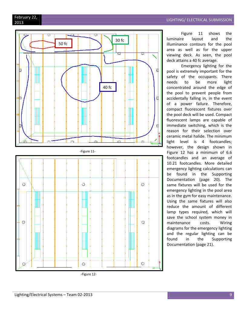
Figure 11 shows the luminaire layout and the illuminance contours for the pool area as well as for the upper viewing deck. As seen, the pool deck attains a 40 fc average. Emergency lighting for the pool is extremely important for the safety of the occupants. There needs to be more light concentrated around the edge of the pool to prevent people from accidentally falling in, in the event of a power failure. Therefore, compact fluorescent fixtures over the pool deck will be used. Compact fluorescent lamps are capable of immediate switching, which is the reason for their selection over ceramic metal halide. The minimum light level is 4 footcandles; however, the design shown in Figure 12 has a minimum of 6.6 footcandles and an average of 10.21 footcandles. More detailed emergency lighting calculations can be found in the Supporting Documentation (page 20). The same fixtures will be used for the emergency lighting in the pool area as in the gym for easy maintenance. Using the same fixtures will also reduce the amount of different lamp types required, which will save the school system money in maintenance costs. Wiring diagrams for the emergency lighting and the regular lighting can be found in the Supporting Documentation (page 21).
-Figure 11-
30 fc
40 fc
50 fc
-Figure 12-

February 22, 2013
LIGHTING/ ELECTRICAL SUBMISSION
Lighting/Electrical Systems – Team 02-2013 10
-Figure 14-
-Figure 13-
4. Education
4.1 Classroom The classrooms in a school are the heart of the building. As such, Nexus
has striven to create spaces that facilitate learning. The lighting solution for this building combines daylight and electric light to give the teachers control over their classroom. The windows for the Reading Elementary School were designed in conjunction with the mechanical and structural teams to create a system that benefits all areas, and reinforces the integration aspect of Nexus. The windows
created are 7 feet by 8 feet, which helped to determine the module of the building to be 7 feet. By allowing all of the classrooms to have the same window, the cost of the building can be reduced due to the modularity. Figure 13 to the right shows the window geometry that will be used. In order to create a comfortable environment, daylight must be delivered
to the space in a manner that lets in plenty of light, without having direct glare from the sun. The main areas of the building that will have an issue with direct sunlight
are located on the southern facing facades. On these facades, the windows will have a louvered exterior overhang; similar to the one pictured in Figure 14 from Hunter Douglas, which will aid in preventing direct, high-angle sun from
entering the room. The overhangs are not deemed necessary on the other faces of the building because they will receive minimal direct sunlight. Also on the southern facades, light shelves will be used to take advantage of the southern sun, to improve the daylighting of the space. Whereas the 8-foot wide exterior overhangs were over each window individually, the light shelves will span the entire width of the classrooms. This, along with the high reflectance of the shelf, will help to more uniformly catch the light at more hours of the day. Figure 15 depicts the sun shading system. A daylight study for a sample classroom can be found in the Supporting Documentation (page 22-27). The general lighting for the classrooms will consist of semi-direct linear luminaires, as seen in Figure 16. These fixtures
have the capability of being dimmed, and will be able to be switched in zones, in relation to the daylight in the space, which will help to save the school energy. The fixtures will use photosensors that the teachers will be allowed to override with a wall-mounted control system to meet their needs while teaching. There will be task lighting as well with wall-mounted fixtures above the whiteboard and under-cabinet lighting by the sink. Occupancy sensors will also be used in the classrooms to help save energy and money.
-Figure 15-
-Figure 16-

February 22, 2013
LIGHTING/ ELECTRICAL SUBMISSION
Lighting/Electrical Systems – Team 02-2013 11
4.2 Classroom Rationale Since cost-effectiveness is one of the driving goals for Nexus, we have designed building systems that are modular. One way that this was achieved was by having the same window throughout all of the classrooms. This will allow for the windows to be built in bulk, and they will all be installed in the same fashion. This will also help to reduce construction time.
The southern façade needs to have daylight control, since it will receive direct sunlight throughout the majority of the school day. Due to this, an overhang/light shelf system has been designed. Overhangs will help to minimize the amount of direct sunlight that enters the space, but are most effective at blocking the high-angle sun. The louvered overhangs are 8 feet long, instead of having one continuous overhang over the length of the building, to be wide enough to cover the entire window while still maintaining coverage for early morning and evening sunlight. The shorter overhang will reduce the amount of material needed and will reduce cost. This sun shading system is also a much lighter system than a solid overhang,
which will reduce the load on the walls. The overhang is paired with the light shelf to allow daylight to penetrate farther into the space, while still blocking direct sunlight at certain times of the day. When the overhang is no longer adequate to block the direct sunlight, fabric shades can be lowered when necessary to block out unwanted sunlight. The results of the daylight study conclude that through much of the winter, the shades will need to be lowered due to the lower angle sun. In the spring and fall, the shades will be able to be raised to take advantage of the sunlight during the school day, especially in the hours past noon. The sunlight will help in creating a pleasant atmosphere conducive to learning. The electric lighting in the classroom will consist of direct-indirect T5 luminaires, as seen in Figure 17, to provide general lighting to the classroom, as well as a wall-mounted T5 luminaire mounted over the whiteboard to provide more light to the space. There will also be under-cabinet task lighting. The electric lighting calculation can be found in the Supporting Documentation (page 28).
Since energy savings is also another concern with the school, the luminaires will be installed with photosensors, which will help to control the luminaires when there is adequate daylight. The photosensors will tell the luminaires to either switch to an off or dimmed state when there is enough daylight in their zone. Each classroom will be divided into 4 zones: two zones controlling the general overhead lighting, one controlling the whiteboard lights, and one controlling the under-cabinet lighting. The zone closest to the windows in the overhead lighting will be the one to be dimmed or switched off depending on the daylight levels. Figure 18 depicts the zoning of the luminaires in a classroom. The purple box represents the whiteboard lights. The green and blue boxes are the overhead lighting zones, and the blue boxes are the zone that will be dimmed in response to the daylight. The
orange box represents the under-cabinet lighting. A more detailed switching/ wiring plan can be found in the Supporting Documentation (page 28).
Table 5 shows the illuminance values with only electric lighting and the LPD of the space. As shown, this design meets the target illuminance level, while saving energy by having an LPD significantly lower than the target.
-Figure 18-
-Figure 17- Axis Lighting
Target Illuminance Actual Illuminance
30 fc 31 fc
Target LPD Actual LPD
1.4 W/ft2 0.94 W/ft2
-Table 5-

February 22, 2013
LIGHTING/ ELECTRICAL SUBMISSION
Lighting/Electrical Systems – Team 02-2013 12
5. Conclusion
In conclusion, Nexus has met the Reading School District’s owner objectives through the support of the project and discipline specific goals. The goals set forth by Nexus were created in order to deliver a building that satisfies the needs of the students, teachers, and community members. The proposed elementary school successfully achieves and exceeds the district’s objectives. The Reading Elementary school contains a plethora of examples of innovative design solutions through each of the integrated disciplines working on the project. Through the use of integration, the lighting/electrical team has striven to provide a plan for the elementary school that is cost effective, energy efficient, and aesthetically pleasing that meets the needs of the owner. The Experience section of the school welcomes students and visitors alike while maintaining a secure feeling. The Community section creates two different spaces that work to give back to the community, as well as to provide versatile facilities to the students. The Education section gives teachers the ability to empower their students with high-quality learning facilities and bright, cheery classrooms. Overall, the lighting/electrical team, and Nexus as a whole, has come together to deliver building systems that are fully integrated to the best of our abilities that meet the owner’s goals efficiently and effectively.

February 22, 2013
LIGHTING / ELECTRICAL SUPPORTING DOCUMENTATION
Lighting / Electrical Systems – Team 02-2013 13
6.1 – Lobby: AGI32 Calculation and Switching Diagram
Calculation Summary
Label Units Avg. Max. Min. Max/Min Lobby FC 15.03 23.3 5.6 4.16 Vestibule FC 20.19 36.1 6.2 5.82
Total Watts 1523.35W LPD 1.098 W/ft2
32W CFL Downlight
150 W CMH Downlight
Decorative Pendant SaSbSc
(6)
2 a
2 a 2 a
2 a
2 a
2 a
4 b
4 b
4 b 6 c
6 c
6 c
6 c 6 c
LP-1, 2, 4, 6
MH = 41.5’
MH = 13.5’
MH = 18’
MH = 22’
MH = 28’

February 22, 2013
LIGHTING / ELECTRICAL SUPPORTING DOCUMENTATION
Lighting / Electrical Systems – Team 02-2013 14
6.2 – Multipurpose Room: Emergency Lighting Calculation
8 fc
7 fc
6 fc
5 fc
4 fc
3 fc
February 22, 2013
LIGHTING / ELECTRICAL SUPPORTING DOCUMENTATION
Lighting / Electrical Systems – Team 02-2013 15
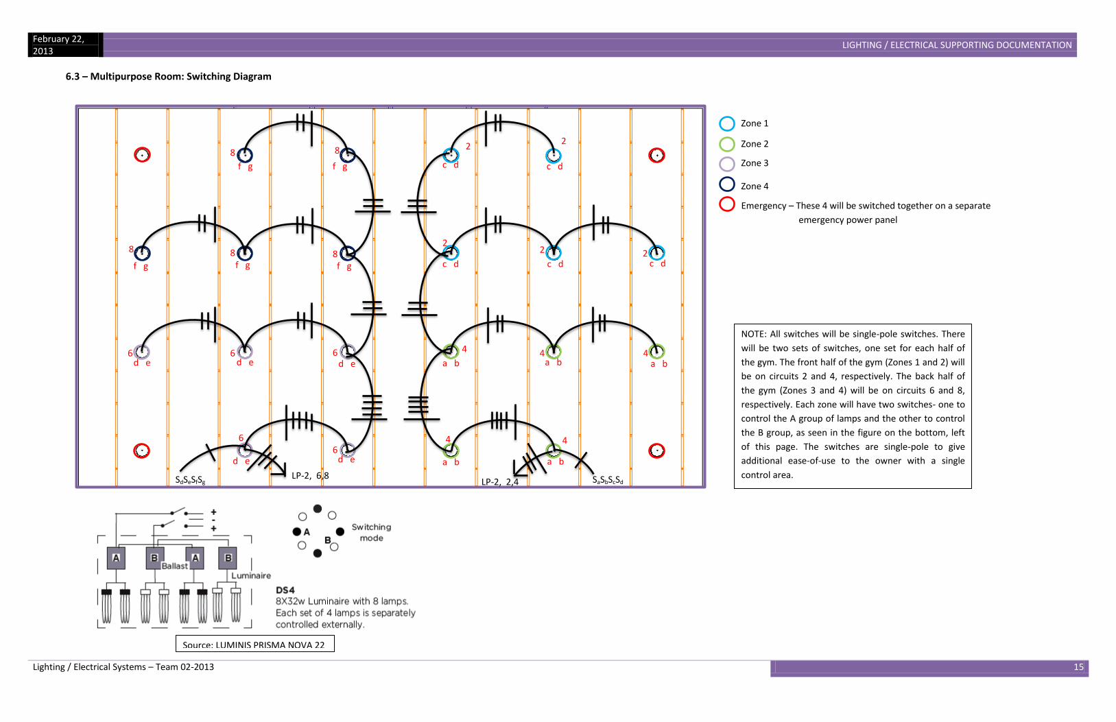
6.3 – Multipurpose Room: Switching Diagram
Zone 1
Zone 2
Zone 3
Zone 4
Emergency – These 4 will be switched together on a separate
emergency power panel
Source: LUMINIS PRISMA NOVA 22
SaSbScSd SdSeSfSg
f g f g f g
f g f g
8
4 8 8
8 8
6 6 6
6 6
d e d e
d e d e d e
a b a b
a b a b a b
c d c d c d
c d c d
2 2
2 2 2
4 4 4
4 4
LP-2, 2,4 LP-2, 6,8
NOTE: All switches will be single-pole switches. There
will be two sets of switches, one set for each half of
the gym. The front half of the gym (Zones 1 and 2) will
be on circuits 2 and 4, respectively. The back half of
the gym (Zones 3 and 4) will be on circuits 6 and 8,
respectively. Each zone will have two switches- one to
control the A group of lamps and the other to control
the B group, as seen in the figure on the bottom, left
of this page. The switches are single-pole to give
additional ease-of-use to the owner with a single
control area.
February 22, 2013
LIGHTING / ELECTRICAL SUPPORTING DOCUMENTATION
Lighting / Electrical Systems – Team 02-2013 16
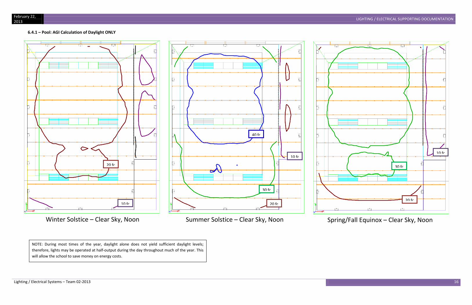
6.4.1 – Pool: AGI Calculation of Daylight ONLY
10 fc
20 fc
Winter Solstice – Clear Sky, Noon
30 fc
40 fc
10 fc
20 fc
Summer Solstice – Clear Sky, Noon
30 fc
20 fc
10 fc
Spring/Fall Equinox – Clear Sky, Noon
NOTE: During most times of the year, daylight alone does not yield sufficient daylight levels;
therefore, lights may be operated at half-output during the day throughout much of the year. This
will allow the school to save money on energy costs.

February 22, 2013
LIGHTING / ELECTRICAL SUPPORTING DOCUMENTATION
Lighting / Electrical Systems – Team 02-2013 17
6.4.2 – Pool: AGI32 Calculation of the Combined Electric Lighting and Daylight
Winter Solstice – Clear Sky, Noon
70 fc
60 fc
50 fc
40 fc
Summer Solstice – Clear Sky, Noon
70 fc
80 fc
90 fc
60 fc
Spring/Fall Equinox – Clear Sky, Noon
80 fc
70 fc
60 fc
50 fc
40 fc
NOTE: Lights may be operated at half-output during the day throughout much of the year when
there is sufficient daylight in the space. This will allow the school to save money on energy costs.

February 22, 2013
LIGHTING / ELECTRICAL SUPPORTING DOCUMENTATION
Lighting / Electrical Systems – Team 02-2013 18
6.4.3 – Pool: AGI32 Calculation of the Combined Electric Lighting and Daylight
Winter Solstice – Cloudy, Noon
40 fc
50 fc
30 fc
Summer Solstice – Cloudy, Noon
50 fc
40 fc
60 fc
70 fc
Spring/Fall Equinox – Cloudy, Noon
40 fc
50 fc
60 fc

February 22, 2013
LIGHTING / ELECTRICAL SUPPORTING DOCUMENTATION
Lighting / Electrical Systems – Team 02-2013 19
6.4.4 – Pool: AGI Calculation of Daylight with Electric Light at Half-Output
40 fc
30 fc
20 fc
Winter Solstice – Clear Sky, Noon
40 fc
50 fc
60 fc
70 fc
Summer Solstice – Clear Sky, Noon
60 fc
50 fc
40 fc
Spring/Fall Equinox – Clear Sky, Noon
NOTE: Lights may be operated at half-output during the day throughout much of the year when
there is sufficient daylight in the space. This will allow the school to save money on energy costs.

February 22, 2013
LIGHTING / ELECTRICAL SUPPORTING DOCUMENTATION
Lighting / Electrical Systems – Team 02-2013 20
6.5 – Pool: AGI32 Calculation of Emergency Lighting
10 fc
9 fc
8 fc
7 fc

February 22, 2013
LIGHTING / ELECTRICAL SUPPORTING DOCUMENTATION
Lighting / Electrical Systems – Team 02-2013 21
6.6 – Pool: Switching/Wiring Diagrams
1
1 1 1
3
3 3 3
(8)
SaSbScSd
a b a b
a b
a b
c d
c d c d c d
10
10
12 12 14
14
16
16
18
18
20 20 22 22 24
24
26
26
28
LP 2:
10,12,14,16,18,20,
22,24,26,28
(10)
(20)
(9)
SaSbScSdSe
SfSgShSiSj
(8) (8) (7) (7)
(6)
(6)
(5)
(5)
(4)
(4)
(3) (3)
a
b b c
c
d
d
e
e
f
f g g
h
h
a
i
i
j

February 22, 2013
LIGHTING / ELECTRICAL SUPPORTING DOCUMENTATION
Lighting / Electrical Systems – Team 02-2013 22
6.7.1 – Classroom: Daylight Analysis – Noon, Clear Sky
NO SHADES
WITH SHADES
Winter: Maximum – 1823 fc Average – 287.49 fc Spring/Fall: Maximum – 191 fc Average – 49.92 fc Summer: Maximum – 135 fc Average – 38.29 fc
Winter: Maximum – 1661 fc Average – 65.05 fc Spring/Fall: Maximum – 60.2 fc Average – 19.04 fc Summer: Maximum – 30.5 fc Average – 12.88 fc

February 22, 2013
LIGHTING / ELECTRICAL SUPPORTING DOCUMENTATION
Lighting / Electrical Systems – Team 02-2013 23
6.7.2 – Classroom: Daylight Analysis – Noon, Cloudy
NO SHADES
WITH SHADES
Winter: Maximum – 43.7 fc Average – 9.10 fc Summer: Maximum – 93 fc Average – 19.36 fc Spring/Fall: Maximum – 73.9 fc Average – 15.38 fc
Winter: Maximum – 6.1 fc Average – 2.54 fc Spring/Fall: Maximum – 10.4 fc Average – 4.30 fc Summer: Maximum – 13.1 fc Average – 5.41 fc

February 22, 2013
LIGHTING / ELECTRICAL SUPPORTING DOCUMENTATION
Lighting / Electrical Systems – Team 02-2013 24
6.7.3 – Classroom: Daylight Analysis – Morning (9 AM), Clear Sky
NO SHADES
WITH SHADES
Winter: Maximum – 805 fc Average – 201 fc Spring/Fall: Maximum – 2096 fc Average – 138.4 fc Summer: Maximum – 124 fc Average – 38.48 fc
Winter: Maximum – 714 fc Average – 30.82 fc Spring/Fall: Maximum – 86.9 fc Average – 27.29 fc Summer: Maximum – 29.2 fc Average – 13.53 fc

February 22, 2013
LIGHTING / ELECTRICAL SUPPORTING DOCUMENTATION
Lighting / Electrical Systems – Team 02-2013 25
6.7.4 – Classroom: Daylight Analysis – Morning (9 AM), Cloudy
NO SHADES
WITH SHADES
Winter: Maximum – 23.8 fc Average – 4.95 fc Spring/Fall: Maximum – 50 fc Average – 10.41 fc Summer: Maximum – 72.3 fc Average – 15.06 fc
Winter: Maximum – 3.3 fc Average – 1.38 fc Spring/Fall: Maximum – 7 fc Average – 2.91 fc Summer: Maximum – 10.2 fc Average – 4.21 fc

February 22, 2013
LIGHTING / ELECTRICAL SUPPORTING DOCUMENTATION
Lighting / Electrical Systems – Team 02-2013 26
6.7.5 – Classroom: Daylight Analysis – Afternoon (3 PM), Clear Sky
NO SHADES
WITH SHADES
Winter: Maximum – 803 fc Average – 74.05 fc Spring/Fall: Maximum – 108 fc Average – 31.94 fc Summer: Maximum – 87.2 fc Average – 28.94 fc
Winter: Maximum – 43.4 fc Average – 13.16 fc Spring/Fall: Maximum – 25.2 fc Average – 10.75 fc Summer: Maximum – 23.4 fc Average – 10.03 fc

February 22, 2013
LIGHTING / ELECTRICAL SUPPORTING DOCUMENTATION
Lighting / Electrical Systems – Team 02-2013 27
6.7.6 – Classroom: Daylight Analysis – Afternoon (3 PM), Cloudy
NO SHADES
WITH SHADES
Winter: Maximum – 24.4 fc Average – 5.07 fc Spring/Fall: Maximum – 55 fc Average – 11.45 fc Summer: Maximum – 74.5 fc Average – 15.50 fc
Winter: Maximum – 3.4 fc Average – 1.42 fc Spring/Fall: Maximum – 7.7 fc Average – 3.20 fc Summer: Maximum – 10.5 fc Average – 4.33 fc

February 22, 2013
LIGHTING / ELECTRICAL SUPPORTING DOCUMENTATION
Lighting / Electrical Systems – Team 02-2013 28
6.8 – Classroom: AGI32 Electric Lighting Calculation and Wiring Diagram
20 fc
30 fc
40 fc
SaSbSc
1 1
1
1
1
b
b
a a
c
NOTE: All switches will be single-pole to facilitate ease-of-use for the
teachers. All controls will be in one central location. The teacher will be
able to control all lights in the classroom. He or she will be able to
override the light levels set by the photosensor, if the need arises, such
as giving a presentation with a projector. The classrooms will also be
equipped with occupancy sensors, to turn the lights on when students or
staff enter the room. The will also be programmed to turn the lights off
when the room is vacant.

February 22, 2013
LIGHTING / ELECTRICAL SUPPORTING DOCUMENTATION
Lighting / Electrical Systems – Team 02-2013 29
Lighting Panel Boards: First and Second Floor

February 22, 2013
LIGHTING / ELECTRICAL SUPPORTING DOCUMENTATION
Lighting / Electrical Systems – Team 02-2013 30
Lighting Panel Board: Third Floor Receptacle Panel: First Floor

February 22, 2013
LIGHTING / ELECTRICAL SUPPORTING DOCUMENTATION
Lighting / Electrical Systems – Team 02-2013 31
Receptacle Panels: Second and Third Floor
February 22, 2013
LIGHTING / ELECTRICAL SUPPORTING DOCUMENTATION
Lighting / Electrical Systems – Team 02-2013 32
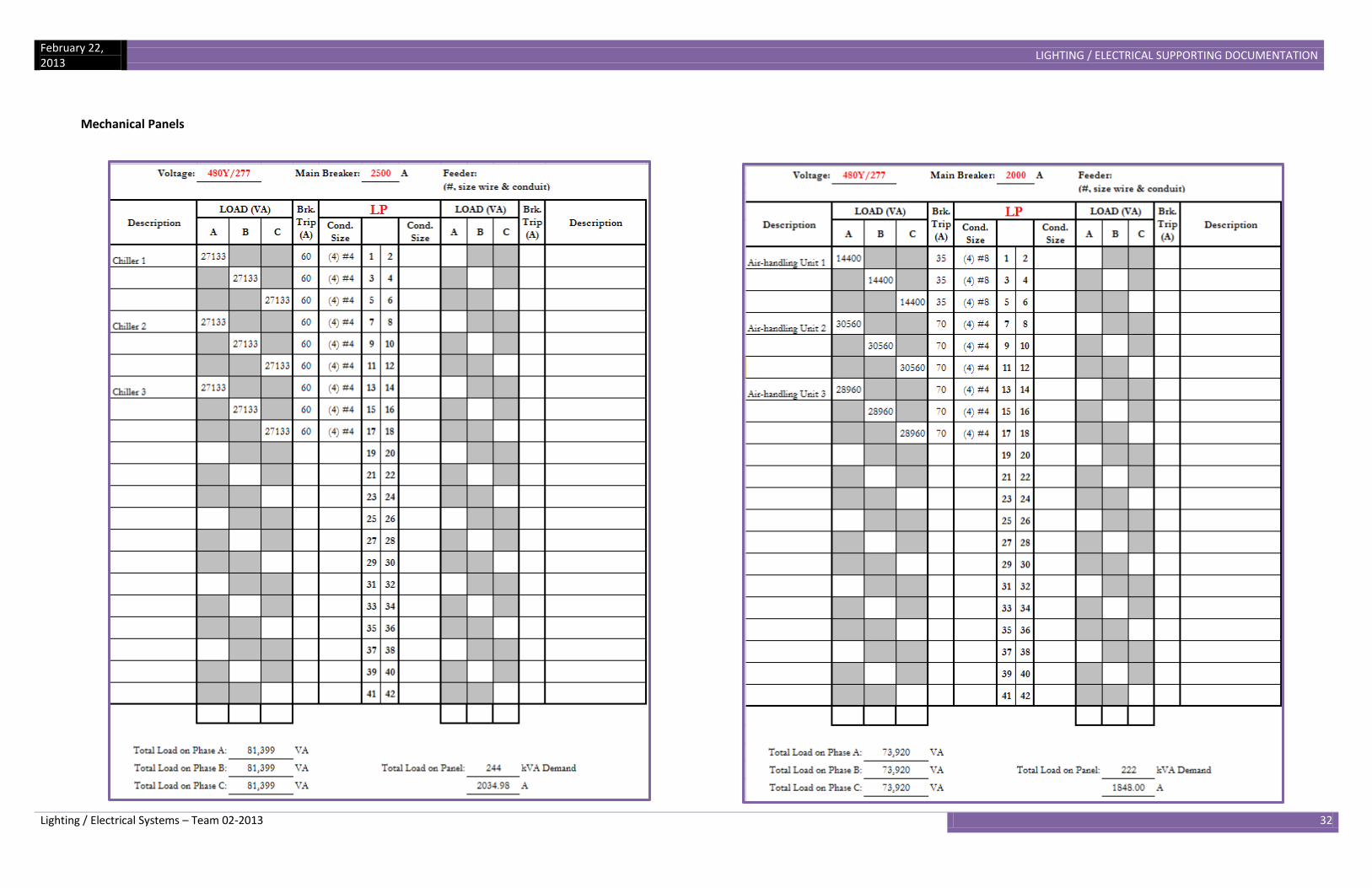
Mechanical Panels

BUILDING INTEGRATION
Scale
Date
Team Registration Number:02-2013
1/16" = 1'-0"
45
Lighting/ElectricalEngineering
2013 ASCE CharlesPankow FoundationAnnual Architectural
EngineeringStudent
Competition
22 February 2013
1/16" = 1'-0"1 First Floor
1/16" = 1'-0"2 Second Floor
1/16" = 1'-0"3 Third Floor
To ensure ease ofmaintenance, all fixtures inthe classrooms and corridorswill use the same T5 lamp. Thelobby on all three floors willuse compact fluorescentlamps for general illumination,as well as for wallwashing.Luminaire layout for theclassrooms and corridors wascoordinated with thestructural and mechanicalteams to ensure no clashingbetween the systems.