2.2 clss pumps.
30
CLSS Section 2.2 CLSS - Hydraulic Pumps CLSS - Hydraulic Pumps Section 2.2 Section 2.2
-
Upload
fauzan-subkhi -
Category
Engineering
-
view
95 -
download
6
Transcript of 2.2 clss pumps.

CLSSSection 2.2
CLSS - Hydraulic PumpsCLSS - Hydraulic Pumps
Section 2.2Section 2.2

CLSSSection 2.2
Hydraulic Pump
HPV95+95 VARIABLE DISPLACEMENT PISTON PUMPHPV95+95 VARIABLE DISPLACEMENT PISTON PUMP112 CC PER PUMP MAX DISPLACEMENT 112 CC PER PUMP MAX DISPLACEMENT Controlled by 2 LS valves and 2 PC valvesControlled by 2 LS valves and 2 PC valves
With an LS EPC and PC EPC With an LS EPC and PC EPC
mounted on the side of the pump bodymounted on the side of the pump body

CLSSSection 2.2
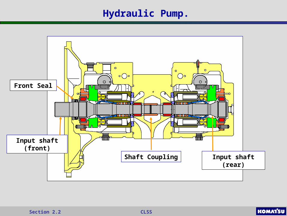
Hydraulic Pump.
TextFront Pump
The two pumps can work independently or together as one.
Rear Pump
CLSSSection 2.2
Hydraulic Pump.
Input Shaft (front)
Input shaft (front)
Front Seal
Shaft Coupling Input shaft (rear)
CLSSSection 2.2
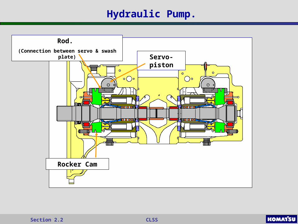
Hydraulic Pump.
Input Shaft (front)Rocker Cam
Servo-piston
Rod.
(Connection between servo & swash plate)

CLSSSection 2.2
Hydraulic Pump.
Input Shaft (front)Shoes Piston Cylinder Block
Valve Plate
CLSSSection 2.2
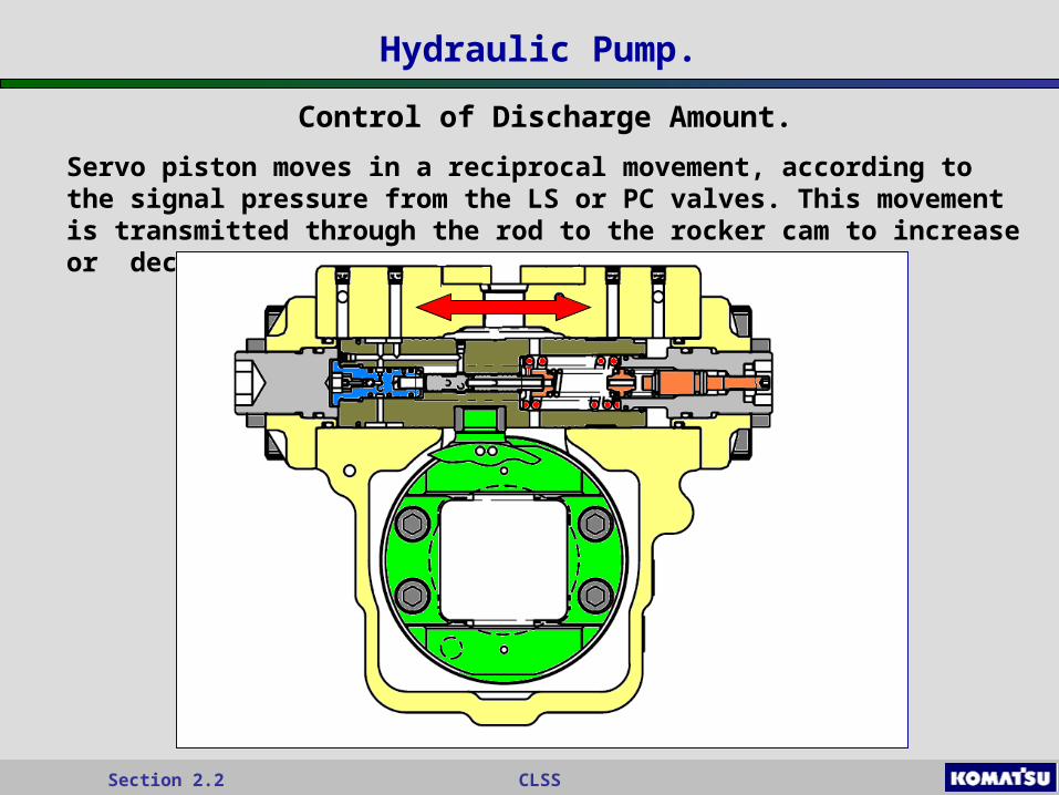
Hydraulic Pump.
Control of Discharge Amount.
Servo piston moves in a reciprocal movement, according to the signal pressure from the LS or PC valves. This movement is transmitted through the rod to the rocker cam to increase or decrease swash plate angle.

CLSSSection 2.2
Hydraulic Pump.
Operation of Pump.
Cylinder block is splined onto input shaft and all rotate together.
When the rocker cam is in the minimum swash plate angle. The volume in the inlet and outlet chamber are the same, discharging a small flow of oil.
The rocker cam is moved into the maximum position, volume in the inlet chamber become larger than the out-let. Causing a greater flow of oil.
The swash plate angle on this pump never becomes 0
Minimum Discharge
Maximum Discharge

CLSSSection 2.2
LS Valve.
LS Valve: Detects the load and controls the pump discharge amount.
The pump discharge or flow is proportional to differential pressure.

CLSSSection 2.2
LS Valve.
Differential Pressure.
PLS = PP – PLS.
PP Main pump Pressure.PLS Control valve outlet Pressure
Main Pump Pressure
Spool
Control Valve Outlet Pressure
CLSSSection 2.2
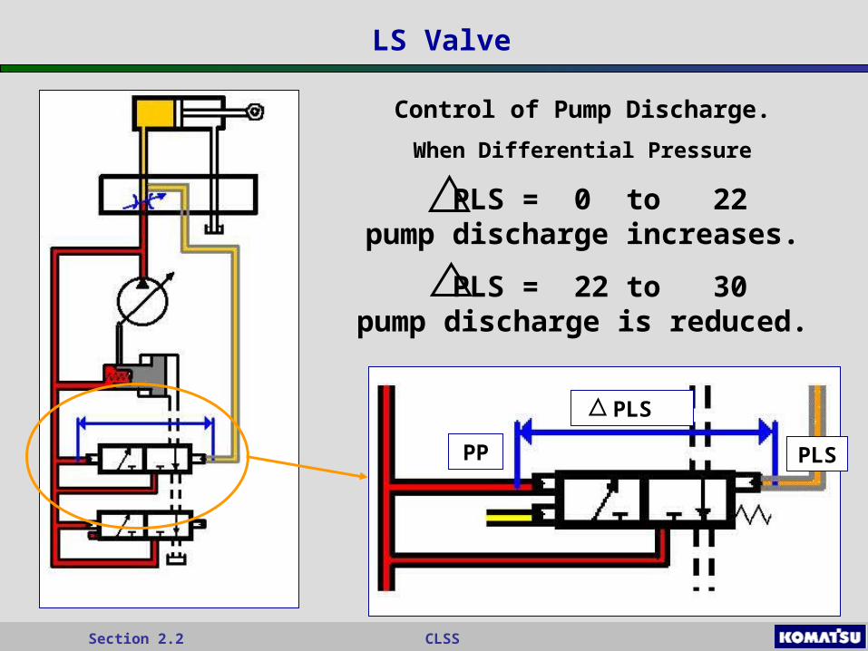
LS Valve
Control of Pump Discharge.
When Differential Pressure
PLS = 0 to 22 pump discharge increases.
PLS = 22 to 30 pump discharge is reduced.
PLS
PP PLS
CLSSSection 2.2
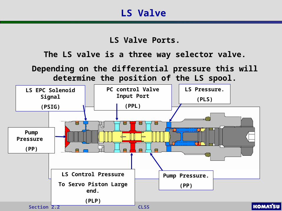
LS Valve
LS Valve Ports.
The LS valve is a three way selector valve.
Depending on the differential pressure this will determine the position of the LS spool.
Pump Pressure
(PP)
LS EPC Solenoid Signal
(PSIG)
PC control Valve Input Port
(PPL)
LS Control Pressure
To Servo Piston Large end.
(PLP)
LS Pressure.
(PLS)
Pump Pressure.
(PP)

CLSSSection 2.2
LS Valve.
Increase Pump Discharge.
When the operator uses the work equipment LS pressure is introduced to the LS valve. Pump pressure is always acting on the LS valve.
With LS pressure (PLS) introduce into the LS valve and with the assistance of the spring and spool area surface is able to over come the pump
pressure (PP) pushing the LS spool to the Left, increasing pump discharge.
PP - PLS = PLS
180 - 170 = 10 Kg/cm2
(Less than 22 Kg/cm2 pump will increase discharge)
PP = 180 Kg/cm2
PLS = 170 Kg/cm2

CLSSSection 2.2
LS Valve.
Decrease Pump Discharge.
When the operator reduces the speed of work equipment or stops working LS pressure is reduced to the LS valve. Pump pressure is always acting
on the LS valve.
With LS pressure (PLS) reduced Pump Pressure is able to overcome LS valve, spring tension and spool area surface. This will push the LS spool
to the Right, decreasing pump discharge.
PP - PLS = PLS
180 - 150 = 30 Kg/cm2
(Greater than 22 Kg/cm2 pump will decrease discharge)
PP = 180 Kg/cm2
PLS 150 Kg/cm2

CLSSSection 2.2
LS Valve.
LS Valve Balanced.
If the work load is maintained at the same flow and load the pump discharge or flow will equalize to the load. When this occurs the pump in neither
increasing of decreasing its discharge. This is the benefit of having CLSS, it will only deliver the oil flow that’s required.
LS pressure, spring tension is equal to Pump Pressure, the LS spool in neither stroking or de-stroking the pump.
PP - PLS = PLS
180 - 158 = 22 Kg/cm2
PP = 180 Kg/cm2
PLS 158 Kg/cm2

CLSSSection 2.2
LS Valve
Control Levers in Neutral.
When the levers are in
the neutral positionThere is no LS pressure (PLS) delivered to the LS
Valve. Pump Pressure (PP) is
able to push the LS spool to the left.
This will introduce PP into the Large end to
servo-piston, because of the difference in servo piston surface area the swash plate is moved to
minimum position.
CLSSSection 2.2
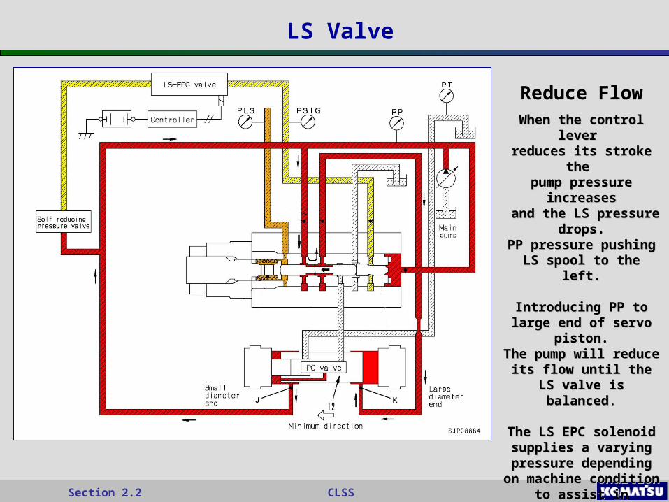
LS Valve
Reduce FlowWhen the control lever When the control lever reduces its stroke the reduces its stroke the
pump pressure increasespump pressure increases and the LS pressure and the LS pressure
drops.drops.PP pressure pushing LS PP pressure pushing LS
spool to the left.spool to the left.
Introducing PP to large Introducing PP to large end of servo piston.end of servo piston.
The pump will reduce its The pump will reduce its flow until the LS valve is flow until the LS valve is
balancedbalanced..
The LS EPC solenoid The LS EPC solenoid supplies a varying supplies a varying
pressure depending on pressure depending on machine condition to machine condition to assist in reducing the assist in reducing the
pump flow pump flow
CLSSSection 2.2
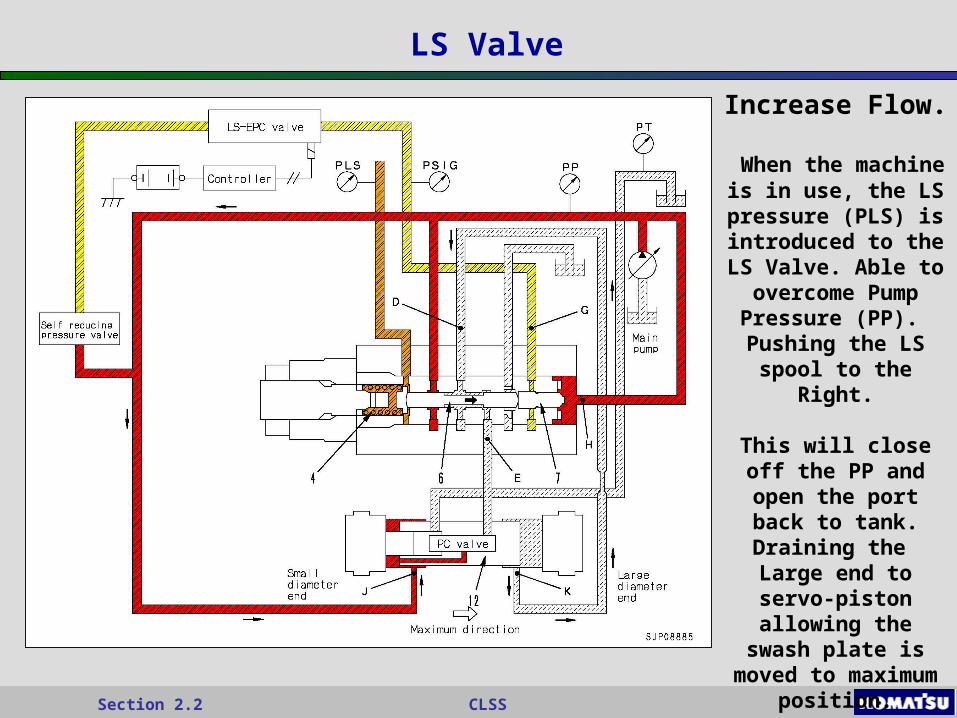
LS Valve
Increase Flow.
When the machine is in use, the LS
pressure (PLS) is introduced to the LS
Valve. Able to overcome Pump Pressure (PP).
Pushing the LS spool to the Right.
This will close off the PP and open the port
back to tank.Draining the Large end to servo-piston allowing the swash plate is moved to
maximum position.
CLSSSection 2.2
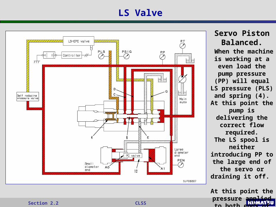
LS Valve
Servo Piston Balanced.
When the machine is working at a even
load the pump pressure (PP) will equal LS pressure
(PLS) and spring (4).At this point the
pump is delivering the correct flow
required.The LS spool is
neither introducing PP to the large end of the servo or draining
it off.
At this point the pressure applied to both ends of servo
piston is 3:5.

CLSSSection 2.2
PC Valve
PC Valve
The PC Valve will maintain equal horse power control so that the horse power absorption by the pump does not exceed the engine horsepower.
If the load during operation increases and pump discharge rises, the PC valve will reduce the pump discharge.

CLSSSection 2.2
PC Control Pressure.
(PPL)
PC Control Pressure.
(PPL)
PC Valve
PC Valve Ports.
The PC valve is a three way hydraulic valve situated inside the Servo piston. The valve is regulated by pump controller via an EPC solenoid in order to reach optimum matching between the load (pressure P) and the
flow (Q). Second Pump Pressure
PP2
Pump Pressure
PP1
PC Mode Select Pilot Pressure
(PM)
Pump Pressure.
(PP1)
Drain Port.
(PT)
CLSSSection 2.2
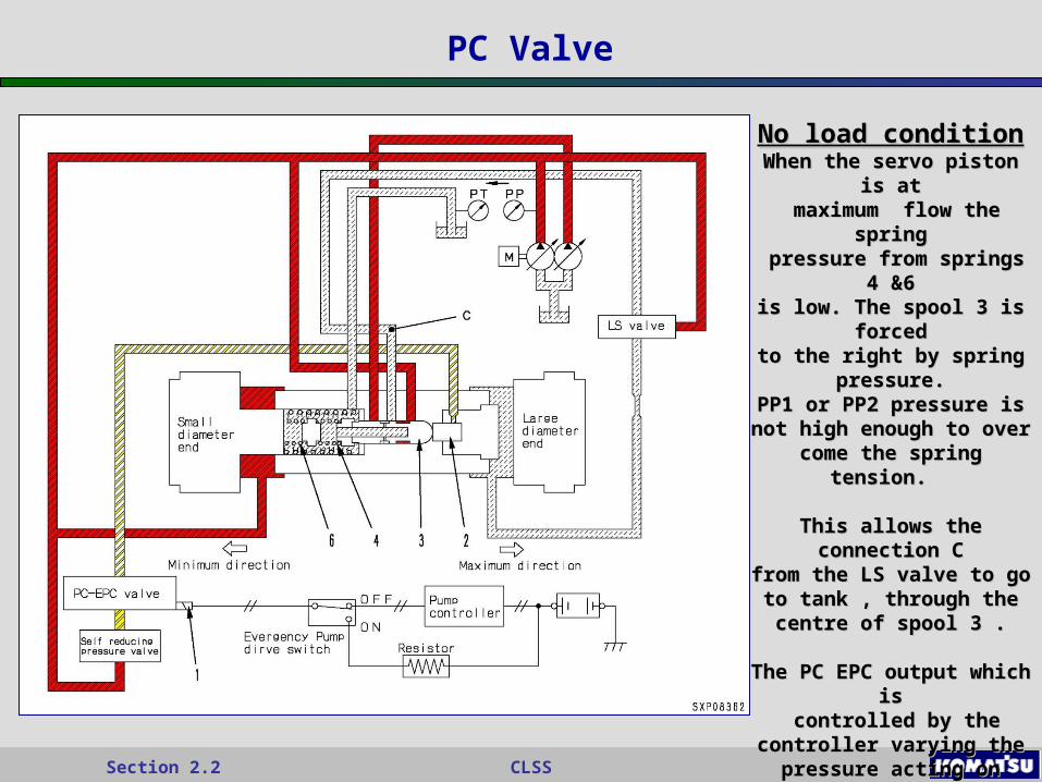
PC Valve
No load conditionNo load conditionWhen the servo piston is atWhen the servo piston is at maximum flow the springmaximum flow the spring
pressure from springs 4 &6pressure from springs 4 &6is low. The spool 3 is forcedis low. The spool 3 is forced
to the right by spring to the right by spring pressure.pressure.
PP1 or PP2 pressure is not PP1 or PP2 pressure is not high enough to over come high enough to over come
the spring tension. the spring tension.
This allows the connection CThis allows the connection Cfrom the LS valve to go to from the LS valve to go to
tank , through the centre of tank , through the centre of spool 3 .spool 3 .
The PC EPC output which isThe PC EPC output which is controlled by the controller controlled by the controller varying the pressure acting varying the pressure acting
on spool 3.on spool 3.Will change the pump torque Will change the pump torque
output.output.

CLSSSection 2.2
PC Valve
High PressureHigh PressureThe pump pressures has The pump pressures has increased enough push increased enough push the PC spool against the the PC spool against the
springs to close off port C springs to close off port C (Return to tank) and (Return to tank) and
introduce Pump pressure. introduce Pump pressure.
This pressure returns to This pressure returns to the large end of the servo the large end of the servo
piston via the LS valve.piston via the LS valve.
As the servo piston is As the servo piston is being pushed back to being pushed back to
reduce the pumps flow, at reduce the pumps flow, at the same time the springs the same time the springs
are being compressingare being compressing
Eventually the spring Eventually the spring tension will equal the pump tension will equal the pump
pressure allowing the pressure allowing the optimum flow at that optimum flow at that particular pressure. particular pressure.
CLSSSection 2.2
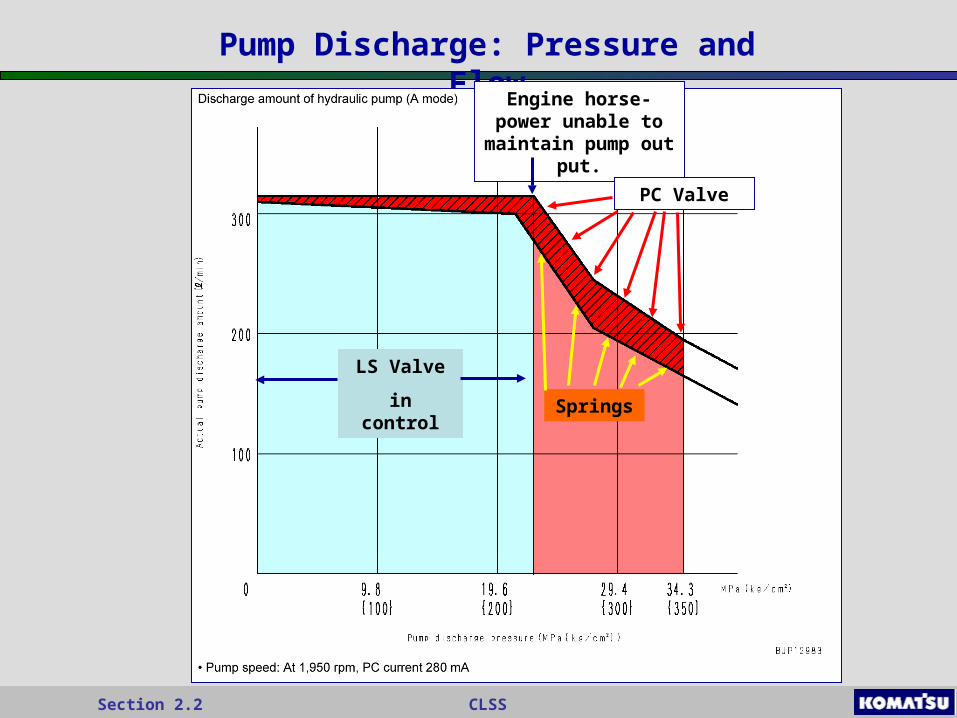
Pump Discharge: Pressure and Flow
LS Valve
in control
Engine horse-power unable to maintain
pump out put.
PC Valve
Springs

CLSSSection 2.2
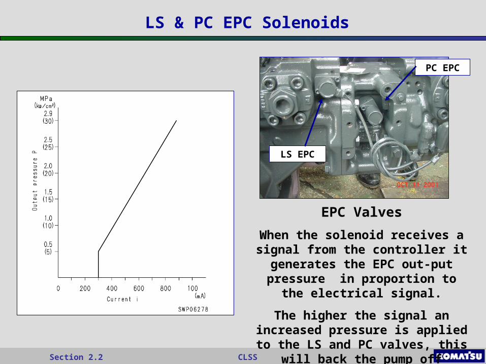
LS & PC EPC Solenoids
PC Prolix Switch ON
If there is a failure in the pump controller, the Prolix Switch can be
switch on to switch to the resistor side, by pass the controller.
When this is done the current becomes
constant so the force pushing the PC valve is
constant. There is no pump sensing.
CLSSSection 2.2
LS & PC EPC Solenoids
EPC Valves
When the solenoid receives a signal from the controller it generates the EPC out-put pressure in proportion
to the electrical signal.
The higher the signal an increased pressure is applied to the LS and PC
valves, this will back the pump off earlier.
LS EPC
PC EPC
CLSSSection 2.2
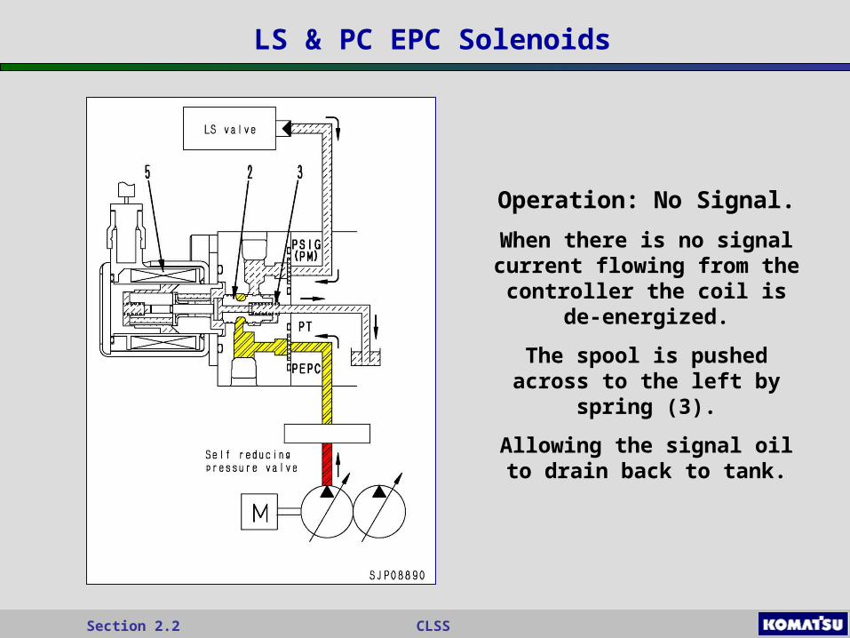
LS & PC EPC Solenoids
Operation: No Signal.
When there is no signal current flowing from the controller the coil is de-
energized.
The spool is pushed across to the left by spring (3).
Allowing the signal oil to drain back to tank.
CLSSSection 2.2
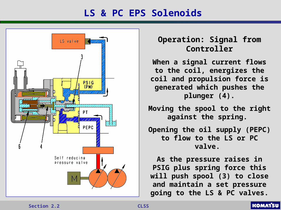
LS & PC EPS Solenoids
Operation: Signal from Controller
When a signal current flows to the coil, energizes the coil and
propulsion force is generated which pushes the plunger (4).
Moving the spool to the right against the spring.
Opening the oil supply (PEPC) to flow to the LS or PC valve.
As the pressure raises in PSIG plus spring force this will push spool (3) to close and maintain a set pressure
going to the LS & PC valves.
CLSSSection 2.2
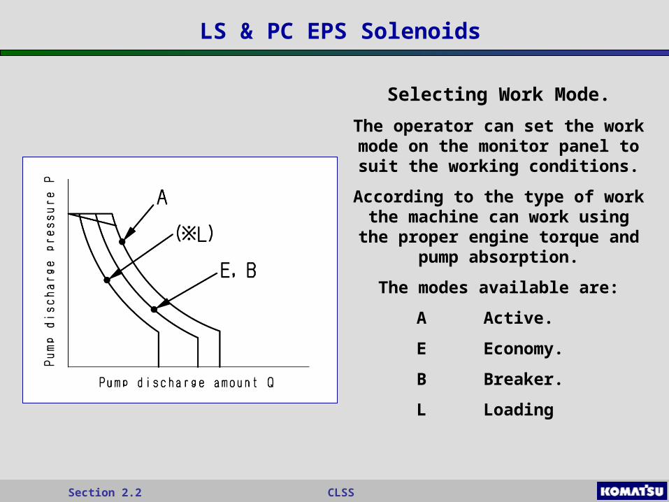
LS & PC EPS Solenoids
Selecting Work Mode.
The operator can set the work mode on the monitor panel to suit the
working conditions.
According to the type of work the machine can work using the proper
engine torque and pump absorption.
The modes available are:
A Active.
E Economy.
B Breaker.
L Loading
CLSSSection 2.2
CLSS Hydraulic Pumps
End ofEnd of
Hydraulic Pumps CLSSHydraulic Pumps CLSS