2100-582(E) (2017 07)E).pdf · bard p/n 8403-058 airconditionerwithcs2000 rc ... r br/w o...
17
Page 1 of 17 LOW VOLTAGE CONTROL CIRCUIT WIRING Models: INSTALLATION INSTRUCTIONS Bard Manufacturing Company, Inc. Bryan, Ohio 43506 www.bardhvac.com Manual No.: 2100-582E Supersedes: 2100-582D Date: 7-26-17 W**A2 W**A2D W**L2 NOTE: For 10 EER models W**AA and W**LA, see low voltage control wiring schematics in unit installation instructions.
Transcript of 2100-582(E) (2017 07)E).pdf · bard p/n 8403-058 airconditionerwithcs2000 rc ... r br/w o...
Page 1 of 17
LOW VOLTAGE CONTROL CIRCUIT WIRING
Models:
INSTALLATION INSTRUCTIONS
Bard Manufacturing Company, Inc. Bryan, Ohio 43506
www.bardhvac.com
Manual No.: 2100-582ESupersedes: 2100-582DDate: 7-26-17
W**A2 W**A2D W**L2
NOTE: For 10 EER models W**AA and W**LA, see low voltage control wiring schematics in unit installation instructions.
Manual 2100-582E Page 2 of 17
Figures
Figure 1 Basic A/C with Optional Electric Heat No Economizer or Vent Packages ................. 5
Figure 2 Opt. MFAD, CRV or ERV Vent. Pkg. w/Programmable T-Stat .......................... 6
Figure 3 Opt. MFAD, CRV or ERV Vent. Pkg. w/Non-Programmable T-Stat ................... 7
Figure 4 A/C with Economizer ............................. 8
Figure 5 A/C w/Dehumidification Sequence & No Vent Pkg. ........................................ 9
Figure 6 A/C w/Dehumidification Sequence & No Vent Pkg. Using Sep. Controls ......... 10
Figure 7 A/C w/Dehumidification Sequence w/Vent Pkg. Using Combination Controller ........ 11
Tables
Table 1 Diagram to Use w/Unit and Vents ............ 3
Table 2 Operating Voltage Range ........................ 3
Table 3 Wall Thermostat .................................... 4
Table 4 Humidity Controls ................................. 4
Table 5 CO2 Controller ....................................... 4
Table 6 Thermostat Wire Size ............................. 4
Installation Wiring – Low Voltage Wiring ................................... 3Operating Voltage Range ....................................... 3Low Voltage Connections ....................................... 3
Figure 8 A/C w/Dehumidification Sequence w/Vent Pkg. Using Non-Prog. T-Stat & Separate Humidity Controller ............................. 12
Figure 9 A/C w/Dehumidification Sequence & Economizer ........................................ 13
Figure 10 A/C w/Dehumidification Sequence & Economizer w/Combination Temperature &
Humidity Control ................................ 14
Figure 11 A/C w/CS2000 Wiring Diagram ............. 15
Figure 12 1-Stage A/C w/Opt. Elec. Heat w/ ............. ECONWM* Style Economizer ............... 16
Figure 13 A/C w/Dehumidification Sequence & ECONWM* Style Economizer with
8403-060 Combination Temperature & Humidity Control ................................ 17
CONTENTS
Manual 2100-582E Page 3 of 17
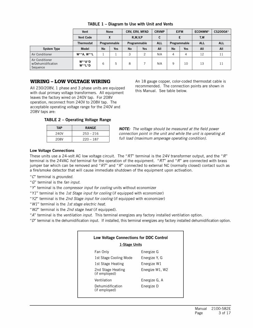
TABLE 1 – Diagram to Use with Unit and Vents
Vent None CRV, ERV, MFAD CRVMP EIFM ECONWM* CS2000A*
Vent Code X R,M,V,P C E T,W
Thermostat Programmable Programmable ALL Programmable ALL ALL
System Type Model No Yes No Yes All No Yes All All
Air Conditioner W**A, W**L 1 1 3 2 N/A 4 4 12 11
Air Conditionerw/Dehumidification Sequence
W**A*DW**L*D 6 5 8 7 N/A 9 10 13 11
NOTE: The voltage should be measured at the field power connection point in the unit and while the unit is operating at full load (maximum amperage operating condition).
WIRING – LOW VOLTAGE WIRINGAll 230/208V, 1 phase and 3 phase units are equipped with dual primary voltage transformers. All equipment leaves the factory wired on 240V tap. For 208V operation, reconnect from 240V to 208V tap. The acceptable operating voltage range for the 240V and 208V taps are:
TABLE 2 – Operating Voltage Range
An 18 gauge copper, color-coded thermostat cable is recommended. The connection points are shown in this Manual. See table below.
Low Voltage ConnectionsThese units use a 24-volt AC low voltage circuit. The “RT” terminal is the 24V transformer output, and the “R” terminal is the 24VAC hot terminal for the operation of the equipment. “RT” and “R” are connected with brass jumper bar which can be removed and “RT” and “R” connected to external NC (normally closed) contact such as a fire/smoke detector that will cause immediate shutdown of the equipment upon activation.
“C” terminal is grounded.“G” terminal is the fan input.“Y” terminal is the compressor input for cooling units without economizer“Y1” terminal is the 1st Stage input for cooling (if equipped with economizer)“Y2” terminal is the 2nd Stage input for cooling (if equipped with economizer)“W1” terminal is the 1st stage electric heat.“W2” terminal is the 2nd stage heat (if equipped).“A” terminal is the ventilation input. This terminal energizes any factory installed ventilation option.“D” terminal is the dehumidification input. If installed, this terminal energizes any factory installed dehumidification option.
TAP RANGE
240V 253 – 216
208V 220 – 187
Low Voltage Connections for DDC Control
1-Stage Units
Fan Only Energize G
1st Stage Cooling Mode Energize Y, G
1st Stage Heating Energize W1
2nd Stage Heating Energize W1, W2 (if employed)
Ventilation Energize G, A
Dehumidification Energize D (if employed)
Manual 2100-582E Page 4 of 17
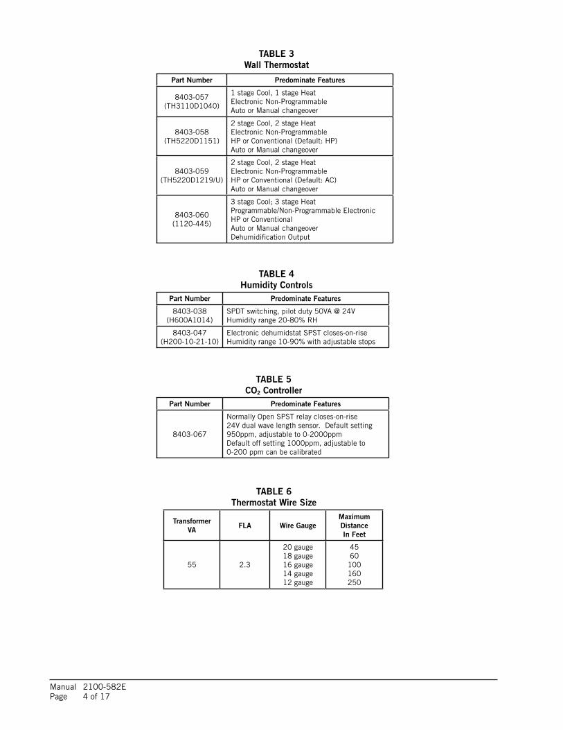
Part Number Predominate Features
8403-057(TH3110D1040)
1 stage Cool, 1 stage HeatElectronic Non-ProgrammableAuto or Manual changeover
8403-058(TH5220D1151)
2 stage Cool, 2 stage HeatElectronic Non-ProgrammableHP or Conventional (Default: HP)Auto or Manual changeover
8403-059(TH5220D1219/U)
2 stage Cool, 2 stage HeatElectronic Non-ProgrammableHP or Conventional (Default: AC)Auto or Manual changeover
8403-060(1120-445)
3 stage Cool; 3 stage HeatProgrammable/Non-Programmable ElectronicHP or ConventionalAuto or Manual changeoverDehumidification Output
TABLE 6Thermostat Wire Size
TABLE 3Wall Thermostat
TABLE 4Humidity Controls
TABLE 5CO2 Controller
Part Number Predominate Features
8403-038(H600A1014)
SPDT switching, pilot duty 50VA @ 24VHumidity range 20-80% RH
8403-047(H200-10-21-10)
Electronic dehumidstat SPST closes-on-riseHumidity range 10-90% with adjustable stops
Part Number Predominate Features
8403-067
Normally Open SPST relay closes-on-rise 24V dual wave length sensor. Default setting 950ppm, adjustable to 0-2000ppmDefault off setting 1000ppm, adjustable to0-200 ppm can be calibrated
TransformerVA FLA Wire Gauge
Maximum Distance In Feet
55 2.3
20 gauge18 gauge16 gauge14 gauge12 gauge
4560
100160250
Manual 2100-582E Page 5 of 17
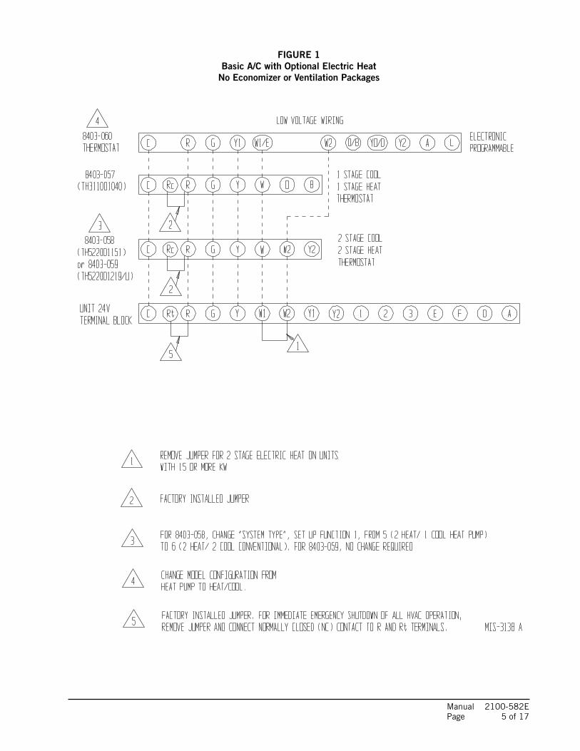
FIGURE 1Basic A/C with Optional Electric Heat
No Economizer or Ventilation Packages
Manual 2100-582E Page 6 of 17
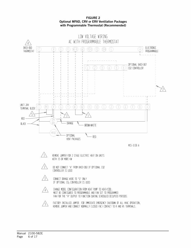
FIGURE 2Optional MFAD, CRV or ERV Ventilation Packageswith Programmable Thermostat (Recommended)
Manual 2100-582E Page 7 of 17
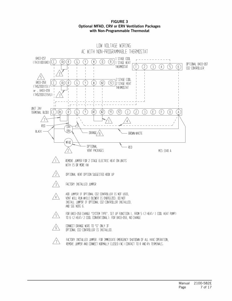
FIGURE 3Optional MFAD, CRV or ERV Ventilation Packages
with Non-Programmable Thermostat
Manual 2100-582E Page 8 of 17
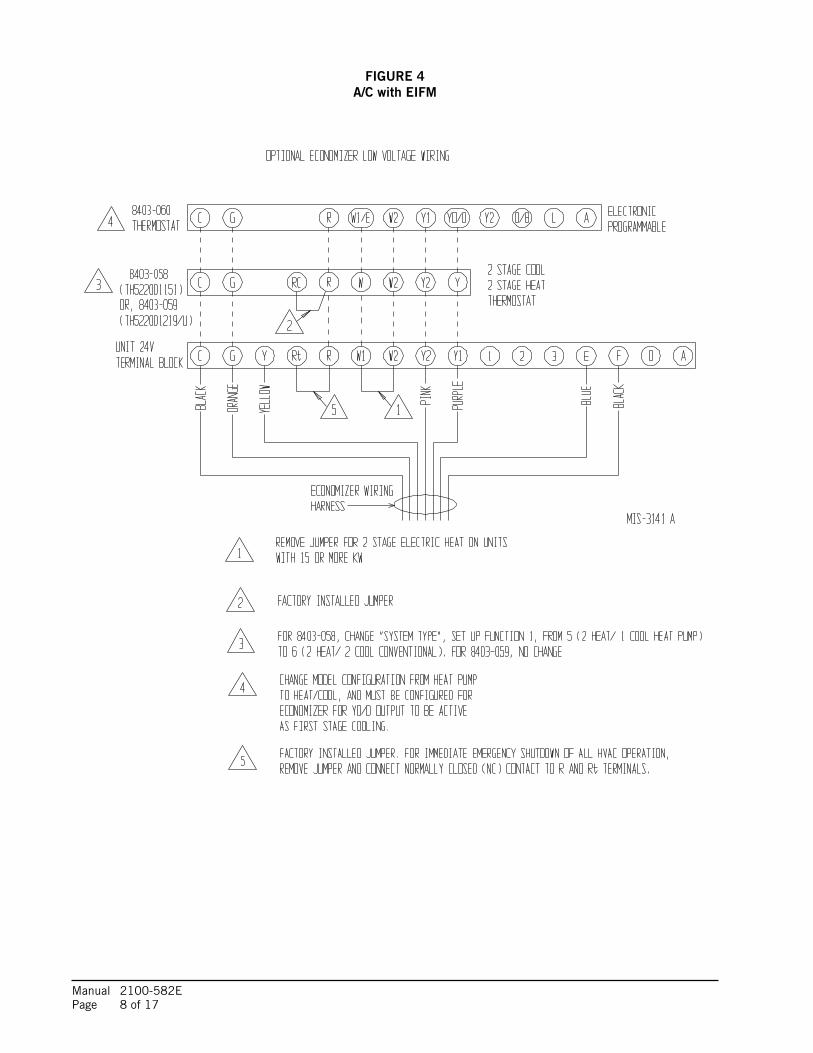
FIGURE 4A/C with EIFM
Manual 2100-582E Page 9 of 17
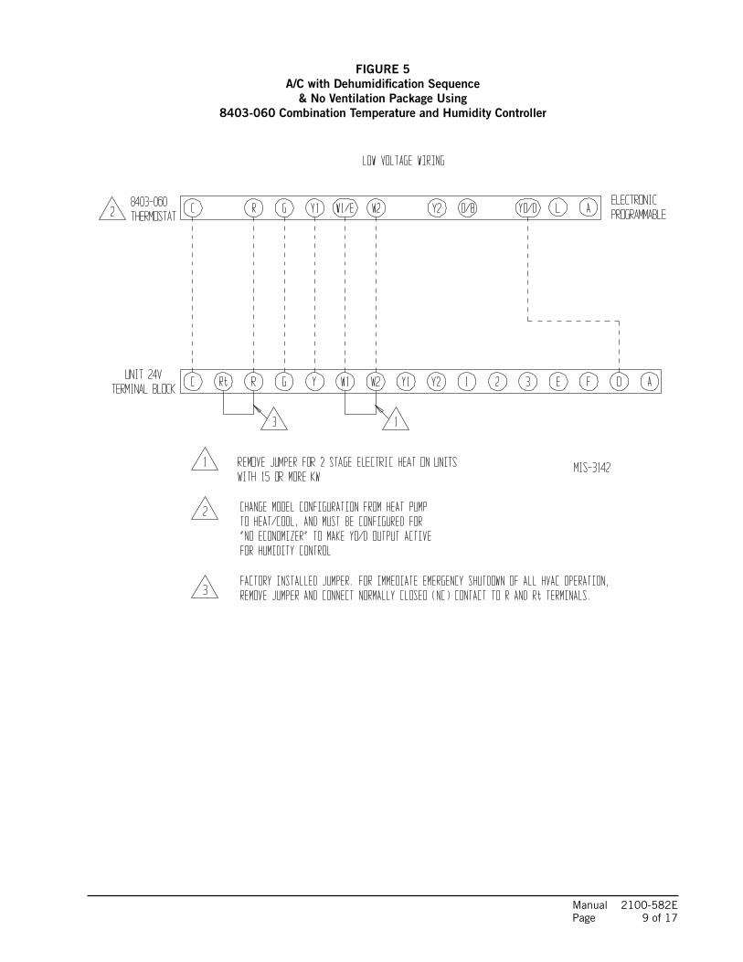
FIGURE 5A/C with Dehumidification Sequence
& No Ventilation Package Using8403-060 Combination Temperature and Humidity Controller
Manual 2100-582E Page 10 of 17
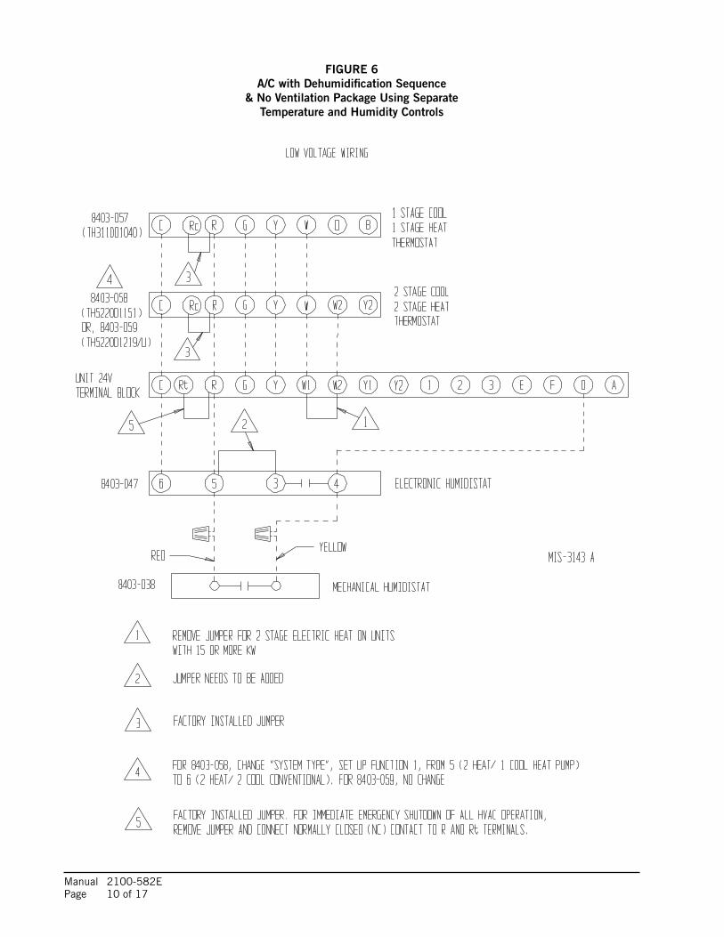
FIGURE 6A/C with Dehumidification Sequence
& No Ventilation Package Using SeparateTemperature and Humidity Controls
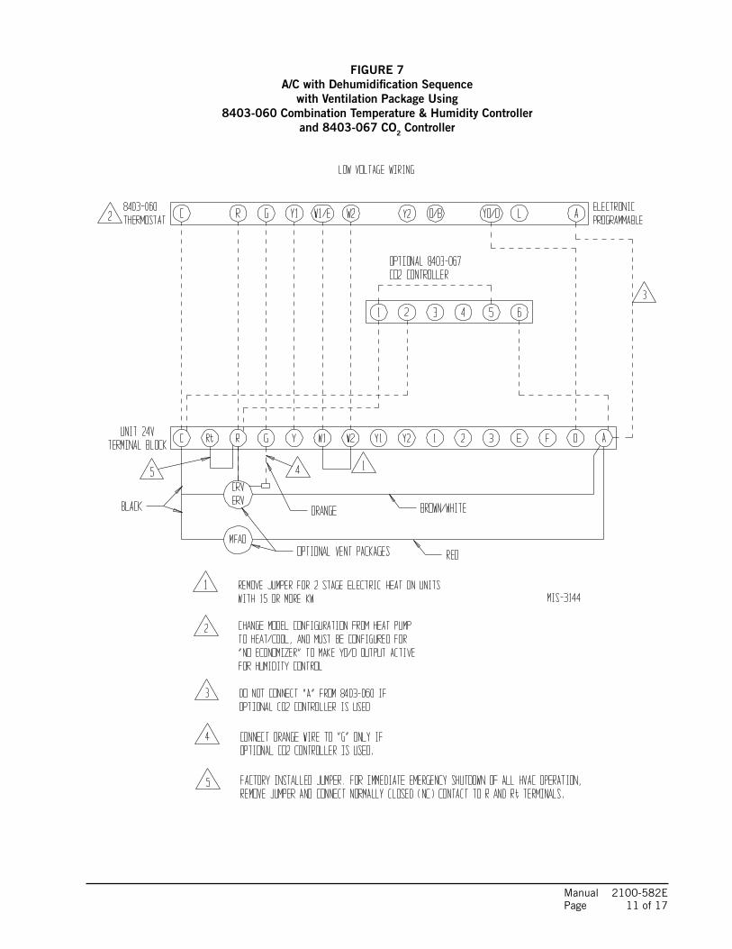
Manual 2100-582E Page 11 of 17
FIGURE 7A/C with Dehumidification Sequence
with Ventilation Package Using8403-060 Combination Temperature & Humidity Controller
and 8403-067 CO2 Controller
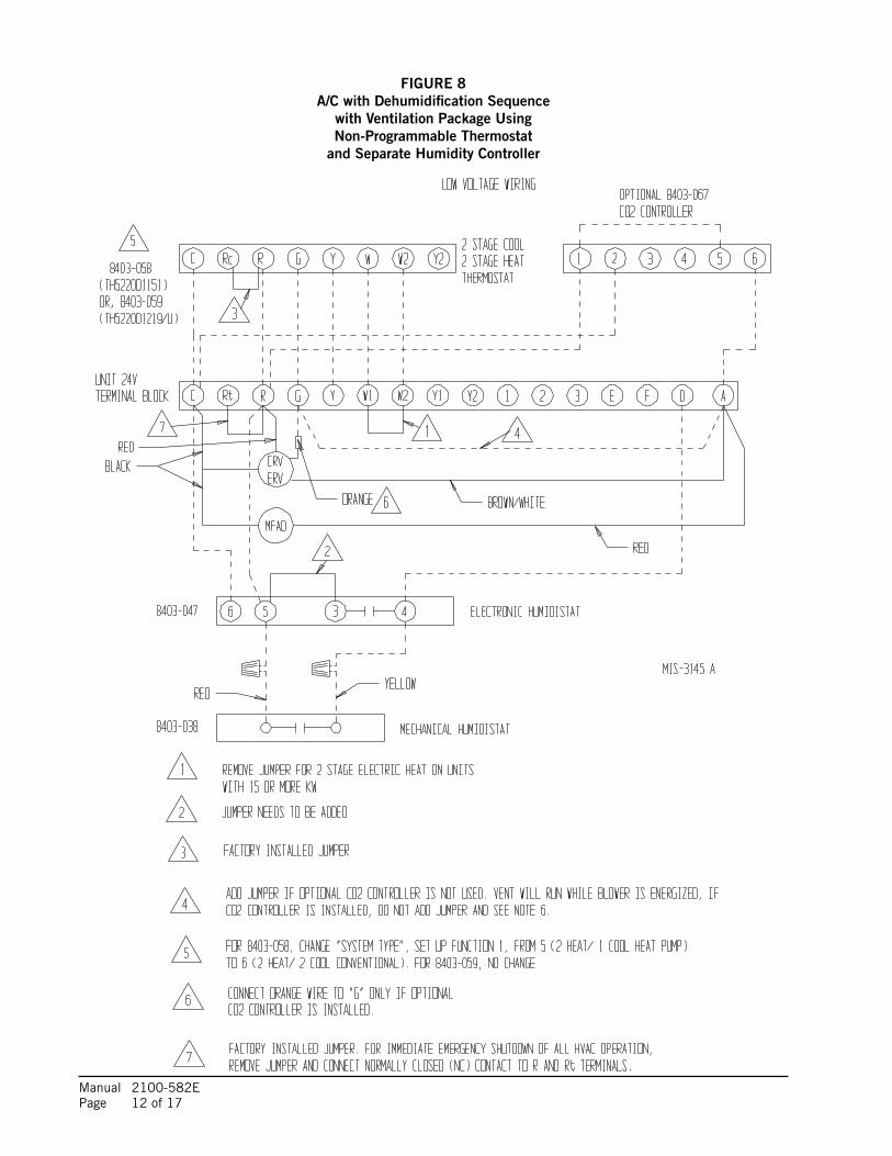
Manual 2100-582E Page 12 of 17
FIGURE 8A/C with Dehumidification Sequence
with Ventilation Package UsingNon-Programmable Thermostat
and Separate Humidity Controller
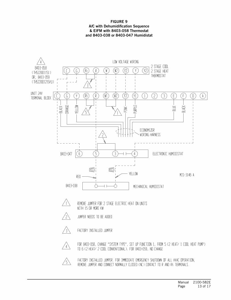
Manual 2100-582E Page 13 of 17
FIGURE 9A/C with Dehumidification Sequence& EIFM with 8403-058 Thermostat
and 8403-038 or 8403-047 Humidistat
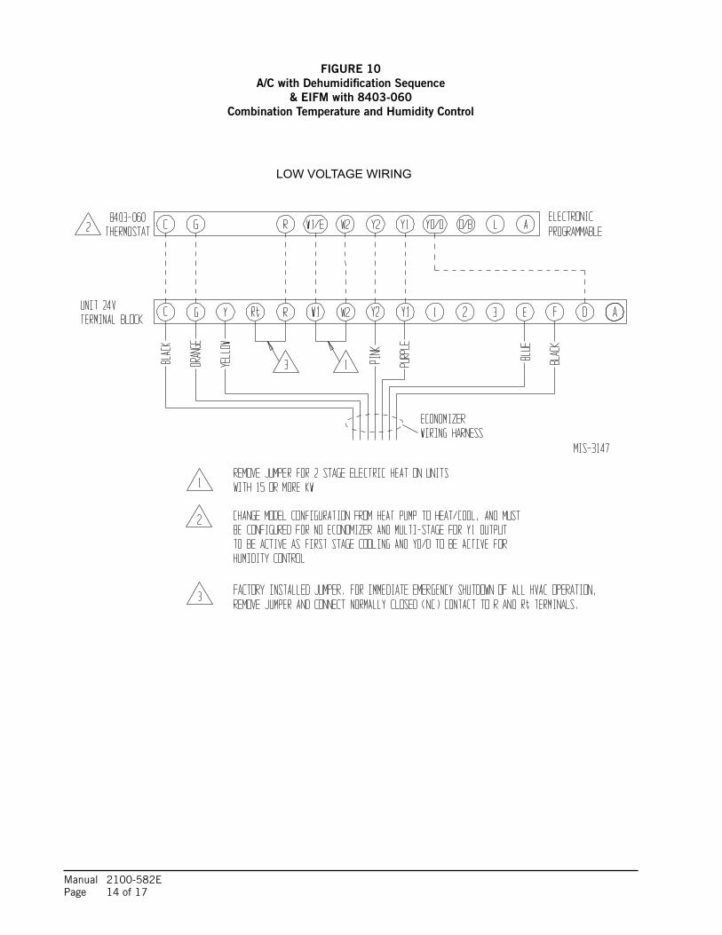
Manual 2100-582E Page 14 of 17
FIGURE 10A/C with Dehumidification Sequence
& EIFM with 8403-060Combination Temperature and Humidity Control
LOW VOLTAGE WIRING
Manual 2100-582E Page 15 of 17
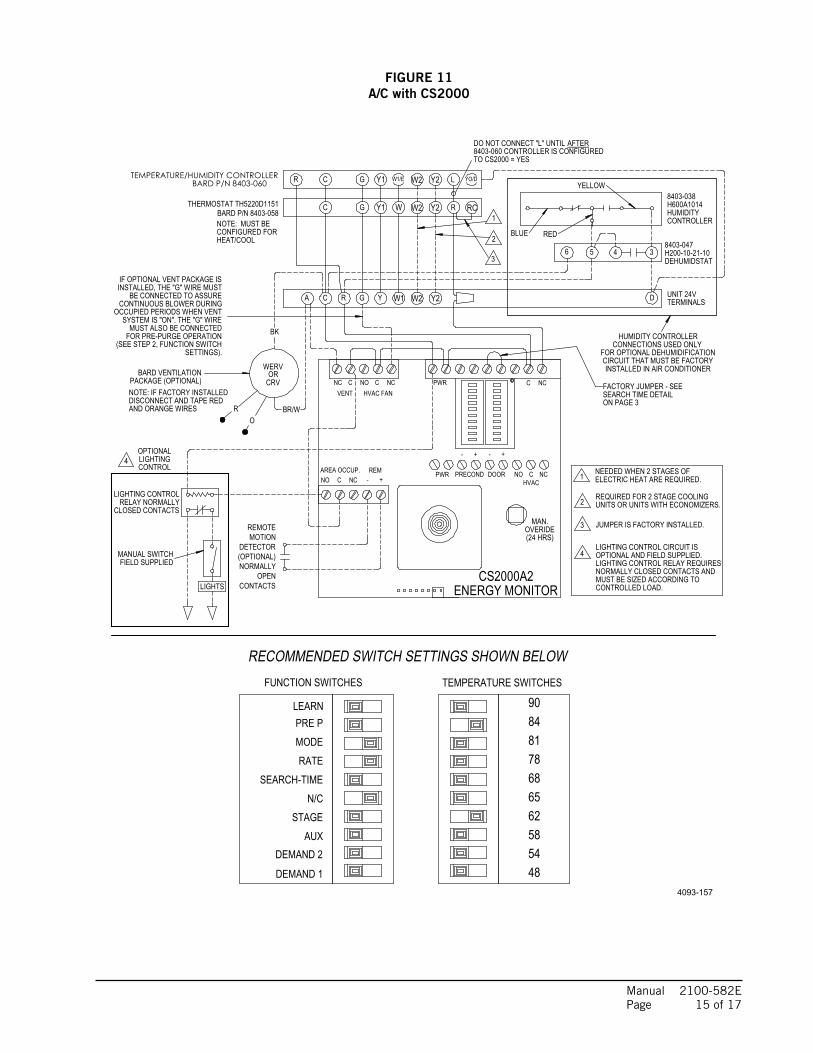
FIGURE 11A/C with CS2000
3
4LIGHTING CONTROL CIRCUIT IS OPTIONAL AND FIELD SUPPLIED.LIGHTING CONTROL RELAY REQUIRESNORMALLY CLOSED CONTACTS ANDMUST BE SIZED ACCORDING TOCONTROLLED LOAD.
JUMPER IS FACTORY INSTALLED.
REQUIRED FOR 2 STAGE COOLINGUNITS OR UNITS WITH ECONOMIZERS.2
NEEDED WHEN 2 STAGES OFELECTRIC HEAT ARE REQUIRED.1
RECOMMENDED SWITCH SETTINGS SHOWN BELOWTEMPERATURE SWITCHES
MODE
FUNCTION SWITCHES
DEMAND 1
DEMAND 2AUX
STAGEN/C
SEARCH-TIME
BARD P/N 8403-060
RATE
LEARNPRE P
48545862656878818490
TEMPERATURE/HUMIDITY CONTROLLER
LIGHTS
DETECTOR
DISCONNECT AND TAPE RED
1
NOTE: IF FACTORY INSTALLED
TO CS2000 = YES
C
Y2
RY2W2
C GR Y W1 W2
G Y1 W
WERV
CRV
MUST ALSO BE CONNECTED
YELLOW
TERMINALS
THERMOSTAT TH5220D1151 BARD P/N 8403-058
AIR CONDITIONER WITH CS2000
RC
UNIT 24V
PACKAGE (OPTIONAL)BARD VENTILATION
AFTERDO NOT CONNECT "L" UNTIL
A
AND ORANGE WIRES
SETTINGS).
CONTACTSOPEN
NORMALLY(OPTIONAL)
MOTIONREMOTE
C NC
MANUAL SWITCH
PWRNC C NO C NC
(SEE STEP 2, FUNCTION SWITCHFOR PRE-PURGE OPERATION
(24 HRS)
- +
REM- +
AREA OCCUP.NO C NC
OVERIDE
ENERGY MONITOR
HVACNO C NCDOORPRECOND
- +
8403-060 CONTROLLER IS CONFIGURED
36 4
VENT HVAC FAN
MAN.
5
CS2000A2
BLUE RED
H600A1014
CONTROLLERHUMIDITY
INSTALLED IN AIR CONDITIONER
PWR
CONNECTIONS USED ONLY
LIGHTING CONTROL
DEHUMIDSTATH200-10-21-108403-047
8403-038
SYSTEM IS "ON". THE "G" WIRE
CLOSED CONTACTSRELAY NORMALLY
OR
4
2
3
FOR OPTIONAL DEHUMIDIFICATION
FIELD SUPPLIED
CIRCUIT THAT MUST BE FACTORY
CONTROLLIGHTINGOPTIONAL
ON PAGE 3
LY2W2G W1/EC Y1 YO/DR
SEARCH TIME DETAILFACTORY JUMPER - SEE
HEAT/COOL
BK
BR/WRO
CONFIGURED FORNOTE: MUST BE
IF OPTIONAL VENT PACKAGE ISINSTALLED, THE "G" WIRE MUST
BE CONNECTED TO ASSURECONTINUOUS BLOWER DURING
OCCUPIED PERIODS WHEN VENT
HUMIDITY CONTROLLER
4093-157
D
Manual 2100-582E Page 16 of 17
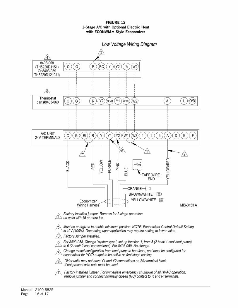
FIGURE 121-Stage A/C with Optional Electric Heat
with ECONWM Style Economizer
C G R 1Y1 2Y2Y A324V TERMINALS W1 EW2A/C UNIT D
1
Factory Jumper Installed.
2is 10V (100%). Depending upon application may require setting to lower value.Must be energized to enable minimum position. NOTE: Economizer Control Default Setting
on units with 15 or more kw.Factory installed jumper. Remove for 2-stage operation
Wiring HarnessEconomizer
part #8403-060 W2GC YO/D Y1 W1/E
3
LThermostat
F
Y2R A O/B
W2
5
RCG YC Y2R
4
TH5220D1219/U)
6
WOr 8403-059
(TH5220D1151)8403-058
12
Low Voltage Wiring Diagram
Factory installed jumper. For immediate emergency shutdown of all HVAC operation,
4
remove jumper and connect normally closed (NC) contact to R and Rt terminals.
5 economizer for YO/D output to be active as first stage cooling.Change model configuration from heat pump to heat/cool, and must be configured for
If not present wire nuts must be used.
3
Rt
Older units may not have Y1 and Y2 connections on 24v terminal block.
67
7
BLAC
K
RED
YELL
OW
PURP
LE
PINK
BLUE
YELL
OW/R
ED
ORANGEBROWN/WHITE
TAPE WIREEND
YELLOW/WHITEMIS-3153 A
For 8403-058, Change "system type", set up function 1, from 5 (2 heat/ 1 cool heat pump)to 6 (2 heat/ 2 cool conventional). For 8403-059, No change.
Manual 2100-582E Page 17 of 17
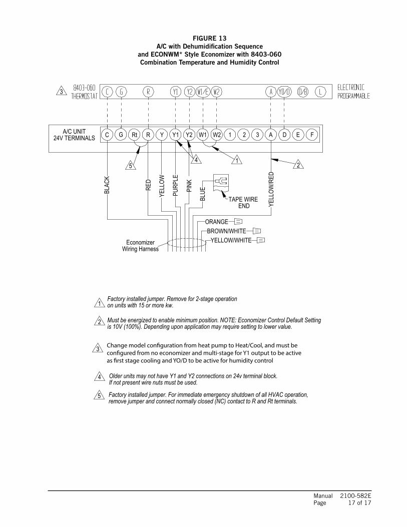
FIGURE 13A/C with Dehumidification Sequence
and ECONWM* Style Economizer with 8403-060Combination Temperature and Humidity Control
C G R 1Y1 2Y2Y A324V TERMINALS W1 EW2A/C UNIT D
Wiring HarnessEconomizer
F
12
Rt
45
BLAC
K
RED
YELL
OW
PURP
LE
PINK
BLUE
YELL
OW/R
ED
ORANGEBROWN/WHITE
TAPE WIREEND
YELLOW/WHITE
1
2is 10V (100%). Depending upon application may require setting to lower value.Must be energized to enable minimum position. NOTE: Economizer Control Default Setting
on units with 15 or more kw.Factory installed jumper. Remove for 2-stage operation
4
Factory installed jumper. For immediate emergency shutdown of all HVAC operation,remove jumper and connect normally closed (NC) contact to R and Rt terminals.
If not present wire nuts must be used.Older units may not have Y1 and Y2 connections on 24v terminal block.
5
Change model con�guration from heat pump to Heat/Cool, and must be con�gured from no economizer and multi-stage for Y1 output to be active as �rst stage cooling and YO/D to be active for humidity control
3
3