2.1 Introduction - INFLIBNETshodhganga.inflibnet.ac.in/bitstream/10603/22827/2/chapter ii.pdf ·...
25
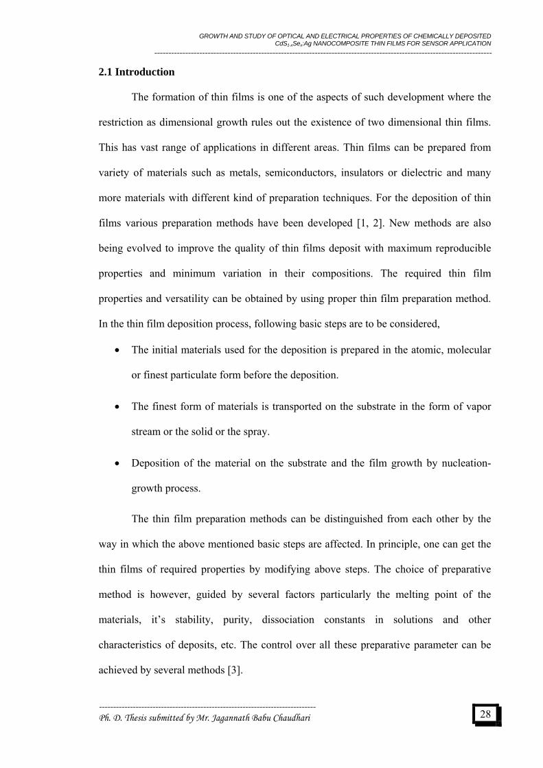
GROWTH AND STUDY OF OPTICAL AND ELECTRICAL PROPERTIES OF CHEMICALLY DEPOSITED CdS 1-x Se x :Ag NANOCOMPOSITE THIN FILMS FOR SENSOR APPLICATION ------------------------------------------------------------------------------------------------------------------------ 2.1 Introduction The formation of thin films is one of the aspects of such development where the restriction as dimensional growth rules out the existence of two dimensional thin films. This has vast range of applications in different areas. Thin films can be prepared from variety of materials such as metals, semiconductors, insulators or dielectric and many more materials with different kind of preparation techniques. For the deposition of thin films various preparation methods have been developed [1, 2]. New methods are also being evolved to improve the quality of thin films deposit with maximum reproducible properties and minimum variation in their compositions. The required thin film properties and versatility can be obtained by using proper thin film preparation method. In the thin film deposition process, following basic steps are to be considered, • The initial materials used for the deposition is prepared in the atomic, molecular or finest particulate form before the deposition. • The finest form of materials is transported on the substrate in the form of vapor stream or the solid or the spray. • Deposition of the material on the substrate and the film growth by nucleation- growth process. The thin film preparation methods can be distinguished from each other by the way in which the above mentioned basic steps are affected. In principle, one can get the thin films of required properties by modifying above steps. The choice of preparative method is however, guided by several factors particularly the melting point of the materials, it’s stability, purity, dissociation constants in solutions and other characteristics of deposits, etc. The control over all these preparative parameter can be achieved by several methods [3]. ----------------------------------------------------------------------------- Ph. D. Thesis submitted by Mr. Jagannath Babu Chaudhari 28
Transcript of 2.1 Introduction - INFLIBNETshodhganga.inflibnet.ac.in/bitstream/10603/22827/2/chapter ii.pdf ·...
GROWTH AND STUDY OF OPTICAL AND ELECTRICAL PROPERTIES OF CHEMICALLY DEPOSITED CdS1-xSex:Ag NANOCOMPOSITE THIN FILMS FOR SENSOR APPLICATION
------------------------------------------------------------------------------------------------------------------------
2.1 Introduction
The formation of thin films is one of the aspects of such development where the
restriction as dimensional growth rules out the existence of two dimensional thin films.
This has vast range of applications in different areas. Thin films can be prepared from
variety of materials such as metals, semiconductors, insulators or dielectric and many
more materials with different kind of preparation techniques. For the deposition of thin
films various preparation methods have been developed [1, 2]. New methods are also
being evolved to improve the quality of thin films deposit with maximum reproducible
properties and minimum variation in their compositions. The required thin film
properties and versatility can be obtained by using proper thin film preparation method.
In the thin film deposition process, following basic steps are to be considered,
• The initial materials used for the deposition is prepared in the atomic, molecular
or finest particulate form before the deposition.
• The finest form of materials is transported on the substrate in the form of vapor
stream or the solid or the spray.
• Deposition of the material on the substrate and the film growth by nucleation-
growth process.
The thin film preparation methods can be distinguished from each other by the
way in which the above mentioned basic steps are affected. In principle, one can get the
thin films of required properties by modifying above steps. The choice of preparative
method is however, guided by several factors particularly the melting point of the
materials, it’s stability, purity, dissociation constants in solutions and other
characteristics of deposits, etc. The control over all these preparative parameter can be
achieved by several methods [3].
----------------------------------------------------------------------------- Ph. D. Thesis submitted by Mr. Jagannath Babu Chaudhari
28
GROWTH AND STUDY OF OPTICAL AND ELECTRICAL PROPERTIES OF CHEMICALLY DEPOSITED CdS1-xSex:Ag NANOCOMPOSITE THIN FILMS FOR SENSOR APPLICATION
------------------------------------------------------------------------------------------------------------------------
2.2 Deposition Techniques
The process of thin film deposition occurs by multiple techniques with its
requirement of being single or multicomponent, alloy/oxide/compound coating on
substrate of different shapes and size. Depending on the nature of way used for the thin
films deposition the technique can be broadly classified as:
• Physical deposition techniques and
• Chemical deposition techniques.
2.2.1 Physical deposition techniques
The physical deposition techniques are those in which the material required for
deposition is made available in the atomic, molecular or particulate form before
deposition. This is usually done at sufficiently high temperature. The condensation of
vapor on substrate material kept at relatively low temperature yields thin film.
Physical deposition can be further subdivided in:
• Thermal evaporation,
• Molecular beam epitaxy,
• Sputtering,
• Electron beam evaporation,
• Ion plating and
• Activated reactive evaporation.
The detailed description of all the physical vapor deposition techniques is beyond
the aim of this dissertation.
----------------------------------------------------------------------------- Ph. D. Thesis submitted by Mr. Jagannath Babu Chaudhari
29

GROWTH AND STUDY OF OPTICAL AND ELECTRICAL PROPERTIES OF CHEMICALLY DEPOSITED CdS1-xSex:Ag NANOCOMPOSITE THIN FILMS FOR SENSOR APPLICATION
------------------------------------------------------------------------------------------------------------------------
2.2.2 Chemical deposition techniques
Chemical deposition techniques are widely used for the growth of thin films due
to their versatility for depositing a very large number of elements and compounds, easily
controllable synthesis parameters at relatively low deposition temperature, etc. [4-6]. The
films can be deposited with required stoichiometric in the form of vitreous and
crystalline layers with high degree of preparation and purity. The various chemical
deposition processes are as follows,
Chemical bath deposition (CBD),
Successive ionic layer adsorption and reaction (SILAR),
• Electrodeposition,
• Anodization,
• Electroless deposition,
• Screen printing,
• Spray pyrolysis and
• Chemical vapor deposition (CVD).
A brief introduction of chemical deposition techniques is given below:
2.2.2a Chemical bath deposition (CBD)
Chemical bath deposition, which is also known as controlled precipitation or
solution growth method, or simply chemical deposition, is recently emerged as a
versatile method for the deposition of metal chalcogenide thin films. In CBD metal
chalcogenide thin films occurs due to substrate maintained in contact with dilute
chemical baths containing the metal and chalcogenide ions. The film formation takes
----------------------------------------------------------------------------- Ph. D. Thesis submitted by Mr. Jagannath Babu Chaudhari
30

GROWTH AND STUDY OF OPTICAL AND ELECTRICAL PROPERTIES OF CHEMICALLY DEPOSITED CdS1-xSex:Ag NANOCOMPOSITE THIN FILMS FOR SENSOR APPLICATION
------------------------------------------------------------------------------------------------------------------------
place when ionic product exceeds solubility products. Lokhande et al. [12] has published
a review article with an emphasis on describing the deposition of various semi
conductors. A review by Mane and Lokhande [5] reported the effect of number of
deposition parameters on structural, optical, electrical and morphological properties of
chemically deposited films such as CdS, CdSe, CdSSe and number of binary and ternary
thin films. Recently, Hodes [6] wrote a book entitled “Chemical Solution Deposition of
Semiconductor Films”. In his book, he had explained fundamental mechanisms of thin
film formation and different aspect related to CBD process, ECPV properties of different
semiconductors, quantum size effect, etc. The chemical bath deposition has numerous
advantages such as:
• The method does not require sophisticated instruments.
• It is ideally suited for large area deposition and substrate of accessible as well as
non-accessible nature.
• Electrical conductivity of the substrate material is not an essential criterion.
• The deposition is possible even at low temperature and avoids the oxidation or
corrosion of the metallic substrate.
• An intimate contact between the reacting solution and the substrate material
permits for pinhole free and uniform deposits on the substrate of complex shape
and sizes.
• Stoichiometry of the deposit can easily be maintained since the basic building
blocks are ions instead of atoms.
• Mixed and doped film structures could be obtained by merely adding the mixent /
dopant solution directly in to the reaction bath.
----------------------------------------------------------------------------- Ph. D. Thesis submitted by Mr. Jagannath Babu Chaudhari
31
GROWTH AND STUDY OF OPTICAL AND ELECTRICAL PROPERTIES OF CHEMICALLY DEPOSITED CdS1-xSex:Ag NANOCOMPOSITE THIN FILMS FOR SENSOR APPLICATION
------------------------------------------------------------------------------------------------------------------------
• The process of film growth is slow, that facilitate better orientation of the
crystallite with improved grain structures.
• The method can be used to deposit a large number of metal chalcogenides.
2.2.2b Successive ionic layer adsorption and reaction (SILAR)
SILAR is relatively new method firstly introduced by Nicolau et al. [7, 8] for the
deposition of metal chalcogenide thin films. It is based on immersion of glass substrate
in to separately place anionic and cationic precursors and rinsing between every
immersion in double distilled water to avoid homogeneous precipitation. In this method,
when substrate is immersed in cationic precursor, cations are adsorbed on the substrate
surface. Rinsing the substrate in double distilled water can separate the unadsorbed or
excess ions out and avoid homogeneous precipitation. When this substrate is immersed
in anionic precursor solution, anions react with preadsorbed cations. The unreacted
powder material can be removed by rinsing the substrate in double distilled water. This
step may be termed as one complete cycle. After repeating such appropriate cycles,
multilayer film formation of appropriate thickness takes place. Quality and thickness of
the film mainly depend upon preparative parameters. A review by Pathan and Lokhande
[9] reports the advantages of SILAR over CBD. Pathan [10] reported some calculations
based on cost effectiveness of SILAR over CBD.
2.2.2c Electrodeposition
It is the process of depositing a material on a substrate; substrate is used as a
electrode by electrolysis, the chemical changes being brought about by the passage of a
current through an electrolyte. The Faraday’s laws govern the phenomenon of
electrolysis. When a metal electrode is dipped in a solution containing ions of that metal,
----------------------------------------------------------------------------- Ph. D. Thesis submitted by Mr. Jagannath Babu Chaudhari
32

GROWTH AND STUDY OF OPTICAL AND ELECTRICAL PROPERTIES OF CHEMICALLY DEPOSITED CdS1-xSex:Ag NANOCOMPOSITE THIN FILMS FOR SENSOR APPLICATION
------------------------------------------------------------------------------------------------------------------------
a dynamic equilibrium is set up. The electrode gains a certain charge on itself which
attract oppositely charged ions and molecules holding them at the electrode / electrolyte
interface. A double layer consisting of a layer of water molecules interposed
preferentially adsorbed ions and outer layer of the charge opposite to that of the electrode
is formed. During deposition, ions reach the electrode surface, stabilize on it, and release
their ligands (water molecules or complexing agent), release their charges and undergo
electrochemical reaction. The rapid depletion of the depositing ions from the double
layer is compensated by a continuous supply of fresh ions from the bulk of the
electrolyte. The transport of the ions to the depletion region occurs due to the diffusion
owing to concentration gradient and migration because of applied electric field and
conventional current. The factors influencing the electrodeposition process are:
• pH of the solution,
• Current density,
• Bath composition,
• Temperature of the bath,
• Electrode shape and
• Agitation.
2.2.2d Anodization
-----------------------------------------------------------------------------
It is an electrolyte process in which the metal substrate is used as a anode in a
suitable electrolyte. When an electric current is passed the surface of the metal is
converted in to its oxide having decorative, protective or other properties. The cathode is
graphite or also a metal where H2 evolves. The required oxygen originates from the
electrolyte used. The pH of the electrolyte plays an important role in obtaining the
coherent films. Thickness of the oxide layer depends on the type of metal, voltage
Ph. D. Thesis submitted by Mr. Jagannath Babu Chaudhari
33

GROWTH AND STUDY OF OPTICAL AND ELECTRICAL PROPERTIES OF CHEMICALLY DEPOSITED CdS1-xSex:Ag NANOCOMPOSITE THIN FILMS FOR SENSOR APPLICATION
------------------------------------------------------------------------------------------------------------------------
applied, temperature of bath and time of deposition. “These may be specially used for
depositing some metal oxides.”
2.2.2e Electroless deposition
Films can be grown on either metallic or nonmetallic substrate by dipping them
in appropriate solution of metals salt without the application of any external electrical
field. Deposition may occur by homogeneous chemical reactions usually reduction of
metal ions in a solution by a reducing agent. If this occurs at a catalytic surface it is
called an electro less deposition. Silvering is most widely used of these techniques. The
growth rate and degree of crystallinity depend upon the temperature of the solution. One
of the main advantages of such a method is to deposit the films on non accessible
surface, i.e., on the inner side of glass tubes etc.
2.2.2f Screen printing
Screen printing is essentially a thick film process in which a paste, containing
film material, is screen printed by a conventional method on a suitable substrate.
Subsequently, the substrate is fixed under appropriate conditions of the film and
temperature, to yield rugged components bounded to the substrate. The substrate that
have smooth surface, capability of withstanding for higher temperature, mechanical
strength and high thermal conductivity and are compatible with film material pastes are
used (alumina, beryllia, magnesia, thoria and zirconia).
2.2.2g Spray pyrolysis
Spray pyrolysis is essentially a thermally stimulated reaction between the clusters
of liquid/vapour atoms of different chemical species. The spray pyrolysis technique
----------------------------------------------------------------------------- Ph. D. Thesis submitted by Mr. Jagannath Babu Chaudhari
34

GROWTH AND STUDY OF OPTICAL AND ELECTRICAL PROPERTIES OF CHEMICALLY DEPOSITED CdS1-xSex:Ag NANOCOMPOSITE THIN FILMS FOR SENSOR APPLICATION
------------------------------------------------------------------------------------------------------------------------
involves spraying of solution (usually aqueous) containing soluble salts of the constituent
atom of the desired compound on a substrate maintained at elevated temperature. The
sprayed droplets on reaching the hot substrate under go pyrolytic decomposition and
form a single crystal or cluster of crystallites of the product. The volatile by-products and
excess solvent escape in the vapour phase. The thermal energy decomposition and
subsequent recombination of the species and sintering and recrystallization of the
crystallites is provided by the hot substrates. The atomization of chemical solution in to a
spray of fine droplets is affected by the spray nozzle with the help of carrier gas, which
may or may not be involved in the pyrolysis reaction. The chemicals used for this
method have to satisfy the following conditions.
• The desired thin film material must be obtained as a result of thermally activated
reaction between the various species/complexes dissolved in the spray solution.
• The remainder of the constituents of the chemical including the carrier liquid
should be volatile at the pyrolysis temperature.
The nature of the substrate, chemical nature and concentration of spray solution,
and chemical spray parameter determine the growth of the film by spray pyrolysis. The
film deposited by this method are generally strong and adherent, mechanically hard,
pinholes free and stable with time and temperature. The topography of the film is
generally rough and depends on spray conditions. Substrate surfaces get affected in the
spray process and the choice is limited to glass, quartz, ceramic or oxides, nitrate or
carbide coated surfaces.
----------------------------------------------------------------------------- Ph. D. Thesis submitted by Mr. Jagannath Babu Chaudhari
35

GROWTH AND STUDY OF OPTICAL AND ELECTRICAL PROPERTIES OF CHEMICALLY DEPOSITED CdS1-xSex:Ag NANOCOMPOSITE THIN FILMS FOR SENSOR APPLICATION
------------------------------------------------------------------------------------------------------------------------
2.2.2h Chemical vapor deposition (CVD)
A simple definition of chemical vapor deposition is the condensation of reactants
from the gas phase on to the substrate to form solid deposition, where reaction occurs to
produce a solid deposit. A liquid or solid compound to be deposited is made gaseous by
volatilization and is caused to flow either by a pressure difference or by the carrier gas to
the substrate. The chemical reaction is initiated near the substrate. In some processes the
chemical reaction may be motivated through an external agency such as heat, RF field,
light, X-rays, electric field or gas flow discharge, electron bombardment, etc. The
morphology, microstructure and adhesion of deposit are strong functions of the nature of
the reaction and the activation process. The possible reactions that are involved in CVD
are: thermal decomposition, hydrogen reduction, nitridation, oxidation, chemical
transport reaction and combined reactions. In most of the reactions, the deposition is
heterogeneous in character. Homogeneous reactions may occur in gas phase resulting in
powder form or flaky deposits.
The feasibility of CVD process can be predicted by studying thermodynamics of
the reactions. The reaction kinetics and mechanism of film growth are so different in
individual processes that generalized account is not possible. However, certain important
features are common to all those methods are: i) CVD set-ups are simple and fast recycle
times are possible, ii) high deposition rates are achieved, iii) depositions of the
compounds and multi-component alloys and control over their stoichiometry is possible,
iv) epitaxial layer of high perfection and low impurity content can be grown, v) objects
of complex shape and geometries can be coated and vi) in-situ chemical vapour etching
of the substrates prior to the deposition is possible.
----------------------------------------------------------------------------- Ph. D. Thesis submitted by Mr. Jagannath Babu Chaudhari
36

GROWTH AND STUDY OF OPTICAL AND ELECTRICAL PROPERTIES OF CHEMICALLY DEPOSITED CdS1-xSex:Ag NANOCOMPOSITE THIN FILMS FOR SENSOR APPLICATION
------------------------------------------------------------------------------------------------------------------------
2.3 Theoretical Background of Chemical Bath Deposition (CBD)Technique
Chemical Bath Deposition technique (CBD) is a low cost technique used for the
growth of large area thin films of metal chalcogenide semiconductors for variety of
applications in different fields. In the chemical bath deposition technique, thin films of
semiconducting materials are deposited on the substrate immersed in dilute solution
containing metal ions and a source of sulfide, selenide or hydroxide ions [11-21]. The
basic principle used in this method is, the controlled precipitation through the use of
suitable complexing agents and amount by controlling the anions in the reaction bath
through the setting of appropriate chemical equilibrium, thin film deposition can take
place. The deposition of thin films can take place through the condensation of metal and
sulphide/selenide ions over the substrate surface. The early research in this area has been
presented in a 1982 review article [11], which attracted many researchers to work in this
area. The progress in this area is given in a 1991 review article [12], which contains the
collection of literature of more than 40 binary and ternary compounds (CdS, CdSe, CuS,
ZnS, InSe, Bi2S3, Bi2Se3, CdS-Bi2S3, CdS-Bi2Se3, SnS, Cd1-xZnxS, Cd1-xZnxSe, CuInS2,
CuInSe2, CdSSe etc.) grown by this technique on different types of substrates. The
considerable progress in this deposition technique makes it feasible for producing
multilayer thin films of metal chalcogenides as well as production of new material alloys
with improved surface and thermal stabilities. Thus, chemical bath deposition technique
is used for the deposition of thin films for number of electronic devices [11], such as
cathode ray tube, color TVs, electroluminescent devices, radiation detectors and laser
colors teleprojectors [12, 13], photovoltaic devices [14-16], window layer material in
tandem solar cells [18, 19], absorber layer material in solar cells[15] and photo
detectors[17]. Hence, looking towards the advantages lead down by chemical bath
----------------------------------------------------------------------------- Ph. D. Thesis submitted by Mr. Jagannath Babu Chaudhari
37

GROWTH AND STUDY OF OPTICAL AND ELECTRICAL PROPERTIES OF CHEMICALLY DEPOSITED CdS1-xSex:Ag NANOCOMPOSITE THIN FILMS FOR SENSOR APPLICATION
------------------------------------------------------------------------------------------------------------------------
deposition technique, it has been used for thin film preparation in the present research
work.
The above-mentioned variety of prospective applications particularly in the field
of photovoltaic devices [21-24], photosensitive detectors [25] and various electronic and
optoelectronics devices [26-28], solar cells [29] has promoted renewed interest in
chemically deposited thin films.
The thin film growth by this method on the substrate takes place by ion-by-ion
condensation instead of cluster-by-cluster condensation or by adsorption of particles
from colloidal solution. The deposition parameters are easily controllable and better
crystalline orientation and improved grain structure can be obtained. Deposition
conditions like the bath temperature, pH of the solution, speed of rotation of substrate,
concentration of solution, reaction time, deposition time and reaction rate, etc. can be
easily controlled to obtained uniform and adherent film deposition at low temperature
[30]. Literature survey reveals the formation of number of binary chalcogenides such
CdS, CdSe, and ternary chalcogenides CdSSe using this simple technique.
It is already been proved that, solid solution system of two or more
semiconductor phases are of great importance in view of their significant role in
technological advancements. They are weakly disordered systems in which disorder is
generated by random distribution of the substitutional atoms at the sites of corresponding
sublattice. So they present unusual combination of semiconducting properties. CdSSe are
such extensively studied solid solution systems.
----------------------------------------------------------------------------- Ph. D. Thesis submitted by Mr. Jagannath Babu Chaudhari
38

GROWTH AND STUDY OF OPTICAL AND ELECTRICAL PROPERTIES OF CHEMICALLY DEPOSITED CdS1-xSex:Ag NANOCOMPOSITE THIN FILMS FOR SENSOR APPLICATION
------------------------------------------------------------------------------------------------------------------------
2.3.1 Solubility and ionic product
When a sparingly soluble salt AB is placed in water, a saturated solution
containing A+ and B- ions in contact with the undissolved solid AB is obtained and
equilibrium is established between the solid phase and the ions in the solutions as,
AB(s) = A+ + B– (2.1)
Applying law of mass action to this equilibrium,
(2.2)
where, CA+, CB
– and CAB are the concentrations of A+, B–, and AB in the solution,
respectively.
)(SCCC
K =AB
BA −+
The concentration of a pure solid phase is a constant number.
+
−+=K
CCK BA (2.3)
i.e., CAB(s) = a constant = K`
or KK` = CA+CB
- (2.4)
As K and K` are constants, the product KK` is also constant, say Ks, therefore equation
(2.4) becomes
Ks = CA+CB
- (2.5)
The constant Ks is called the ‘solubility product (SP)’ and the expression (CA+CB
-) is
called as the ‘ionic product (IP)’.
When the solution is saturated, the ionic product (IP) is equal to the solubility
product (SP). It follows that when the IP exceeds the SP, i.e., IP/SP>1, the solution is
supersaturated and precipitation occurs and ions combine on the substrate and in the
solution to form nuclei. When the IP < SP, the solution will be unsaturated. The
temperature, solvent and particle size are three main factors, which affect the SP [31-33].
----------------------------------------------------------------------------- Ph. D. Thesis submitted by Mr. Jagannath Babu Chaudhari
39

GROWTH AND STUDY OF OPTICAL AND ELECTRICAL PROPERTIES OF CHEMICALLY DEPOSITED CdS1-xSex:Ag NANOCOMPOSITE THIN FILMS FOR SENSOR APPLICATION
------------------------------------------------------------------------------------------------------------------------
2.3.2 Growth of thin films
Thin films of metal chalcognides are obtained by the bulk precipitation of
solution. The reaction of a metal solution takes place with an aqueous solution of a
compound capable of giving chalcogenide ions under suitable conditions. Thiourea,
thioacetamide or sodium selenosulphate are the commonly used compounds, which
furnish sulphur or selenium ions respectively by hydrolysis in alkaline media [34-38]. In
case of alkaline bath chemical deposition of film take place by the process of ion-by-ion
and cluster-by-cluster deposition. The ion-by-ion growth results in thin, hard, adherent
and specularly reflecting films whereas cluster-by-cluster growth gives thick, powder
diffusively reflecting films.
Once nucleation occurs, the deposition rate rises rapidly until the rate of
deposition becomes equal to zero i.e. IP = SP or S = 1 (S = degree of supersaturation).
Consequently, film attains a terminal thickness, which is maximum attainable thickness
(under given set of experimental conditions) therefore it is also called ‘terminal
thickness’. For nucleation to start, certain time period requires, it is referred to as
‘incubation period’. When substrates are suspended in container before forming the
complex in the solution, film thickness increases linearly and hence, show that the nuclei
for the formation of film are provided by the solution itself.
2.3.3 Precipitate formation in the solution
-----------------------------------------------------------------------------
The formation of a solid phase from a solution involves two steps one is the
nucleation growth and other is particle growth. The size of the particles of a solid phase
is dependent upon the relative rates at which these two competing processes take place. It
also depends on deposition temperature, rate of mixing reagents, concentration of
reagents and the solubility of the precipitate during precipitation. All of these can be
related to the relative supersaturation of the system. A state of supersaturation may be
Ph. D. Thesis submitted by Mr. Jagannath Babu Chaudhari
40

GROWTH AND STUDY OF OPTICAL AND ELECTRICAL PROPERTIES OF CHEMICALLY DEPOSITED CdS1-xSex:Ag NANOCOMPOSITE THIN FILMS FOR SENSOR APPLICATION
------------------------------------------------------------------------------------------------------------------------
achieved by lowering the temperature of an unsaturated solution and formation of the
solute in the solutions at a fixed temperature.
For any precipitate, there is some minimum number of ions or molecules required
to produce a stable second phase in contact with a solution called a nucleus. The rate at
which nuclei formed in a solution is dependent on the degree of supersaturation. In
highly supersaturated solution, the rate of nucleation increases exponentially.
Rate of nucleation = K0 (Q – S)X (2.6)
where, K0 and X are constants and X>1, Q the excess concentration above saturation s
the concentration at saturation. The second step is the growth of particles already present
(AB)
in the solution. This begins when nuclei or other seed particles are present. In case of
ionic solid, the process involves deposition of cations and anions on appropriate sites.
(AB)n + A+ + B– (AB)n+1 (2.7)
+ –
where ‘ st com ine in
le particle (AB) te of gro th is directly p
supersaturation.
surface area of exposed solid and K0` is a constant that is characteristic
the precipitation, the relatively few nuclei formed will grow to give a small number of
large particles. With high supersaturation, many more nuclei are formed initially and
nucleation may occur throughout the entire precipitation process. As a result, there are
many more centers upon which the growth process can take place, none of the particles
can become very large and colloidal suspension is formed.
n+1 + A + B (AB)n+2 (2.8)
n’ is the minimum number of A+ and B– ions that mu b order to yield
the stab n. The ra w roportional to the
Rate of growth = K0`A(Q – S) (2.9)
where ‘A’ is the
of the particular precipitate. If the supersaturation is maintained at a low level throughout
----------------------------------------------------------------------------- Ph. D. Thesis submitted by Mr. Jagannath Babu Chaudhari
41
GROWTH AND STUDY OF OPTICAL AND ELECTRICAL PROPERTIES OF CHEMICALLY DEPOSITED CdS1-xSex:Ag NANOCOMPOSITE THIN FILMS FOR SENSOR APPLICATION
------------------------------------------------------------------------------------------------------------------------
The colloidal suspension consists of finely divided solid particles in a liquid
phase with diameters of 0.01 to 0.1 µm. Under some circumstances, colloidal particles
can com
drop wise addition of
of both the ions to be precipitated and the
reagent
following equation.
H4+ +
ea
s negl ro erties e
control
e together and adhere to one another and the resulting solid is called a ‘colloidal
precipitate’ and the process by which it is formed is termed as ‘coagulation’ or
‘agglomeration’. Colloidal particles when agglomerated have quite different properties
from a crystalline solid since the particles are arranged irregularly.
2.3.4 Controlled precipitation in the solution
The degree of supersaturation can be reduced by the slow,
the reagent and by the use of dilute solutions
. In precipitation, from homogeneous solution, the precipitating agent is
chemically generated in the solution. Local reagent excess does not occur because the
precipitating agent appears slowly and homogeneously throughout the entire solution;
the relative supersaturation is thus kept low. The necessity for careful control of the pH
has long been recognized. This is accomplished by making use of the hydrolysis of urea,
which decomposes into ammonia and carbon dioxide as follows:
CS(NH2)2 + H2O 2NH3 +CO2 (2.10)
Ammonia hydrolysis in water provides OH– ions according to the
NH3+H2O N OH- (2.11)
Thus urea is often used for the homogeneous generation of hydroxide ion. Ur
possesse igible basic p p soluble in wat r and its hydrolysis rate can be easily
led. It hydrolyses rapidly at 363-373 K and hydrolysis can be quickly terminated
at a desired pH by cooling the reaction mixture to room temperature. The use of a
hydrolytic reagent alone does not result in the formation of a compact precipitate. The
physical character of the precipitate will be very much affected by the presence of certain
----------------------------------------------------------------------------- Ph. D. Thesis submitted by Mr. Jagannath Babu Chaudhari
42

GROWTH AND STUDY OF OPTICAL AND ELECTRICAL PROPERTIES OF CHEMICALLY DEPOSITED CdS1-xSex:Ag NANOCOMPOSITE THIN FILMS FOR SENSOR APPLICATION
------------------------------------------------------------------------------------------------------------------------
anions. The main function of ‘suitable anion’ is the formation of a basic salt, which
seems responsible for the production of a compact precipitate. The pH of the initial
solution must be appropriately adjusted. Moreover, by varying the rate of the chemical
reaction producing the precipitant in homogenous solution, it is possible to alter further
the physical appearance of the precipitate, the slower the reaction, the larger are the
crystals formed. Homogeneous precipitation of crystalline precipitates also results in
larger crystallites as well as improvement in the purity.
2.4 Effect of Preparative Parameters
The terminal thickness and the rate of deposition depend upon the number of
nucleation centers, supersaturation of the solution (given by ratio of IP/SP), and stirring.
The gro
tration leads to an increase in ‘X’ ion
larger thickness is obtained. However, above a
certain
n concentration decreases with increase in concentration of
uently, the rate of reaction and hence precipitation is reduced
leading
wth kinetics depends on the concentration of ions, their velocities and nucleation
and growth processes on immersed substrates. The effect of various deposition
conditions on these parameters is discussed below.
2.4.1 Anion compound concentration
The increase in anion (X) compound concen
concentration and a film of MX with
concentration, when rate of reaction becomes high, precipitation also becomes
important which leads to lesser amount of MX on the substrates and hence lower
thickness is obtained.
2.4.2 Complexing agent
The metal io
complexing ions. Conseq
to a larger terminal thickness of the film. Stability constants indicate affinity of
the complexant to the metal ion and their tendency to keep the metal ions in solution
even at a pH range where metal hydroxide precipitation is possible. If complex formed is
----------------------------------------------------------------------------- Ph. D. Thesis submitted by Mr. Jagannath Babu Chaudhari
43

GROWTH AND STUDY OF OPTICAL AND ELECTRICAL PROPERTIES OF CHEMICALLY DEPOSITED CdS1-xSex:Ag NANOCOMPOSITE THIN FILMS FOR SENSOR APPLICATION
------------------------------------------------------------------------------------------------------------------------
too stable, the reduction of metal ion by weak reluctant may be completely inhibited. If
the complexant is not sufficiently stable, spontaneous reduction in the bulk of solution
will take place if strong reducing agents are used. The complexant selected should not
lead insoluble complexes that are complex with no charge on them. Negatively charged
complexes greatly influence the properties of the metal ion and hence the mechanism of
deposition. Complexing agents used are acetates, hydroxyacetates, succinates, hydroxy
propionates, triethanol amine, malonates, glycollates, lactates, pyrophosphates, citrates,
tartarates, ammonia, disodium salt of ethylenediamine tetra-acetic acid (Na2 EDTA)
[39], etc.
2.4.3 pH
The reaction rate and the rate of deposition depend on supersaturation: the lower
aturation, the slower the formation of MX (where M is metal ion concentration
and X
e anion of the compound (x-compound)
erature. At higher temperatures, the dissociation is greater and gives
higher
the supers
is anion ion concentration). If the concentration of OH– ion in the solution is
higher, the M ion concentration will be lower and the reaction rate will be slow. With an
increase in the pH as the M ion concentration decreases, the rate of deposition of MX is
decreased and increases the terminal thickness. At a certain pH, the concentration of M
ions decreases to a level such that the ionic product of M and X becomes less than the
solubility product of MX and a film is formed.
2.4.4 Temperature
The dissociation of the complex and th
depend on the temp
concentrations of M and X ions (number of metal and chalcogenide ions), which
result in higher rates of depositions. The thickness increases or decreases with increase in
the bath temperature depending on the conditions under which films are prepared. At low
pH values, supersaturation is high even at low temperature and increases further with
----------------------------------------------------------------------------- Ph. D. Thesis submitted by Mr. Jagannath Babu Chaudhari
44

GROWTH AND STUDY OF OPTICAL AND ELECTRICAL PROPERTIES OF CHEMICALLY DEPOSITED CdS1-xSex:Ag NANOCOMPOSITE THIN FILMS FOR SENSOR APPLICATION
------------------------------------------------------------------------------------------------------------------------
increasing temperature. This results in formation of precipitation and consequently lower
thickness is obtained. At high pH values, precipitation is limited due to the low
supersaturation and most of the product is formed on the substrate surface. Further the
thermal dissociation of complex and anion compound is increased at high temperatures
so that more M and X ions are available for MX formation and thus higher thickness is
obtained.
2.4.5 Substrate
Film formation can take place only under certain conditions, i.e., either under
ions for MX formation or when the substrate has special properties
facilita
he
m insoluble chalcogenide under the same conditions of deposition and
provide
ctivity is
lled photoconductivity. This effect occurs in organic or inorganic
materia
of photon of sufficiently high energy by a
optimum condit
ting for formation of single crystal films. The second condition favours the
formation because when the lattice of the deposited material matches well with that of
the substrate the free energy change is smaller, which facilitates nucleation formation.
2.4.6 Doping
Impurities in the starting materials can be incorporated into the films only if t
impurities for
d their corresponding ionic product is greater than the solubility product. Doping
affects thickness, physical and chemical properties of the host film [40].
2.5 Photodetection
When a semiconductor is illuminated by light often increase in its condu
observed and it is ca
ls. With the combination of different parameters such as spectral response, dark
resistance, rise and decay time of the photoconductivity, etc., only few materials are
useful for practical uses in photodetection.
The photoconductivity process can be understood with the help of band picture of
solid. In intrinsic materials, the absorption----------------------------------------------------------------------------- Ph. D. Thesis submitted by Mr. Jagannath Babu Chaudhari
45

GROWTH AND STUDY OF OPTICAL AND ELECTRICAL PROPERTIES OF CHEMICALLY DEPOSITED CdS1-xSex:Ag NANOCOMPOSITE THIN FILMS FOR SENSOR APPLICATION
------------------------------------------------------------------------------------------------------------------------
solid ra
σph = e(nµn – pµp) (2.12)
where s and holes
ely. µn µp
photo conducting
produ ing ‘f’
p h e n n p p) (2.15)
The process involved in photoconductivity is quite complex [41] due to presence
of defect in the film materials such as vacancies, dislocation, grain boundaries, etc. in
materia
ises electron from valance band to conduction band, creating holes in valence
band. In extrinsic material free carriers are also produced by exciting the donor or
acceptor atoms.
Photoconductivity of material at constant light intensity is given by
‘e’ is electronic charge, ‘n’ and ‘p’ be the number of electron
respectiv and are the corresponding mobility. Photoconductivity is induced by
absorption of light wave. The condition for such phenomenon is hν ≥ Eg. The threshold
frequency ν = e.Eg/h with the incident light energy greater than eEg there will be change
in carrier density with out changing there mobility, thus affecting the conductivity. The
change in conductivity of material due to light irradiation is given by,
∆σph= e (∆n µn+ ∆pµp) (2.13)
This when expressed in terms of light intensity of excitation (L) on a
material c electron hole pairs per unit volume per unit photon absorbed and
free carrier life time ‘τ’ through the relation,
∆n = f. τn and ∆p = f. τp (2.14)
∆σ = f = (µ τ + µ τ
l which acts as trapping or recombination centers of the carriers, these
imperfections present in the solid plays an important role in heterojunction. The traps are
localized as positive potential centers for electrons and as negative potentials for holes.
So there will be localized discrete energy levels, i.e., traps in the band gap in the vicinity
----------------------------------------------------------------------------- Ph. D. Thesis submitted by Mr. Jagannath Babu Chaudhari
46

GROWTH AND STUDY OF OPTICAL AND ELECTRICAL PROPERTIES OF CHEMICALLY DEPOSITED CdS1-xSex:Ag NANOCOMPOSITE THIN FILMS FOR SENSOR APPLICATION
------------------------------------------------------------------------------------------------------------------------
of the conduction band and valance band, respectively. When the traps are filled, the net
charge then vanishes.
When electron or hole falls in the trap, it spends some finite time there and will
no long
Consider a shallow trapping level ‘Et’ placed between the bottom of conduction
band ‘
(2.16)
here c carrie
tocurrent Iph is proportional to number of carriers available for
conduc
(2.17)
en ity L, but in
(2.18)
er be free to move and then it is raised to conduction or valance band. The traps
can capture electrons and holes and the probabilities of the opposite charges recombine is
greatly increased thereby terminating there free lifetime. Such traps are called
‘recombination centers’. These centers affect the density of free carriers and there free
lifetime. Hence photoconductivity of the material is affected.
Ec’ and fermi level ‘Ef’. Then number of carriers ‘n’ available to conduction
current will be less due to trapping of carriers than the steady state number ‘n0’ generated
by incident light. The relation between n and ‘n0’ is given by
( )KTE
NN
nn
nnn c −==−
expTt0
w N umber of trap rs, NT – is the density of state in conduction band, nt – n
density of traps.
The pho
tion.
( )KTEI Ph
−∝ exp
In trap free cases, photoconductivity is proportional to the light int s
presence of traps Iph will not be a linear function of L; it is modified as
Iph α Lx
----------------------------------------------------------------------------- Ph. D. Thesis submitted by Mr. Jagannath Babu Chaudhari
47

GROWTH AND STUDY OF OPTICAL AND ELECTRICAL PROPERTIES OF CHEMICALLY DEPOSITED CdS1-xSex:Ag NANOCOMPOSITE THIN FILMS FOR SENSOR APPLICATION
------------------------------------------------------------------------------------------------------------------------
where the magnitude of ‘x’ varies from 0.5 to 1.0, the Iph versus ‘L’ relation varies from
linear to sub linear [42]. The current will mainly be carried by the carriers of one sign,
i.e. majority carriers [43]. The recombination process is of two types, i.e. radioactive and
non radioactive. The spectral response of photocurrent gives important information like
thermally stimulated current. The photocurrent spectra shows peak near absorption edge
which is related to energy band gap of solid [44]. The peaks with lower magnitude are
also observed and these are due to impurity levels in the forbidden gap. It is thus possible
to probe inside the energy structure especially of trap and recombination centers by
photoconductivity measurements.
Fig. 2.1: Schematic diagram illustrating different types of electronic transitions due to photon absorption.[41]
Electrons, holes, or- traps, excited states
There are few other parameters, which are important in assessing the efficiency
of photoconductivity. These parameters are life time (t) of carriers; collision cross
section (s) of traps, concentration of traps (Nt), time required by electron (hole) between
two electrodes, voltage applied in between two electrodes (V), etc.
When photon is absorbed by semiconductor various electronic transitions takes
place leading to photoconductivity of materials. These are shown in Fig. 2.1. Here ‘1’
shows the production of electron hole pair in conduction and valance band, respectively
----------------------------------------------------------------------------- Ph. D. Thesis submitted by Mr. Jagannath Babu Chaudhari
48

GROWTH AND STUDY OF OPTICAL AND ELECTRICAL PROPERTIES OF CHEMICALLY DEPOSITED CdS1-xSex:Ag NANOCOMPOSITE THIN FILMS FOR SENSOR APPLICATION
------------------------------------------------------------------------------------------------------------------------
due to absorption of high-energy photon. ‘2’ indicates absorption of photon at a localized
imperfection site producing free electron and also a hole.
Hole being bound to a neighboring defect center and free electron moves to the
conduction band contributing to photoconductivity under an impressed voltage. ‘3’
shows, absorption of photon as a result of which electron from valance band is raised to
unoccupied impurity level, which (i.e., electron) remain bound to defect site leaving a
free hole in valance band for conduction. ‘5’ and ‘5`’ represent the capture of electron in
trap center and its thermal excitation to conduction band, respectively. ‘4’ and ‘4`’ are
similar process for holes. ‘6’ and ‘7’ represent the capture of hole and electron
respectively in the two-recombination centers. ‘8’ represent the combination of free
electron directly with free hole; this radioactive emission is ‘edge emission’. ‘9’
represents capture of electron by excited centers containing a hole. ‘10’ represents hole
capture by excited center containing electron. The transition ‘9’ and ‘10’ may be
radioactive.
Any transition that creates additional free carriers, it effectively increases the free
life time as well as the photosensitivity of the material. The ratio of increase in
conductivity of the material in presence of light to the conductivity in darkness gives the
value of photosensitivity and is given by equation
(2.19) tivityPhotosensiD
Dph
D
Dph
VVV
I=
II −−=
∆=
σσ
(2.20) 100tivityPhotosensi % XV ⎬⎨=
VV
D
Dph
⎭
⎫
⎩
⎧ −
where, ‘Iph’ and ‘ID’ are current under illumination and in dark, respectively. ‘Vph’ and
‘VD’ are the corresponding voltages, respectively. Assuming, however, that the specimen
resistance ‘Rph’ and ‘RD’ under illumination and dark is much larger than standard
resistance used across which voltages are measured.
----------------------------------------------------------------------------- Ph. D. Thesis submitted by Mr. Jagannath Babu Chaudhari
49

GROWTH AND STUDY OF OPTICAL AND ELECTRICAL PROPERTIES OF CHEMICALLY DEPOSITED CdS1-xSex:Ag NANOCOMPOSITE THIN FILMS FOR SENSOR APPLICATION
------------------------------------------------------------------------------------------------------------------------
References
1. R. Glang, “Handbook of thin film technology” (Ed. L. I. Maissel and R. Glang,
Mc-Graw Hill, New York) (1970) P1.
2. L. Holland, “Vacuum Deposition Of Thin Films” (John Wiely, New York)
(1956).
3. S. Borase, Ph. D. Thesis, North Maharashtra University, Jalgaon. (2007).
4. L. P. Deshmukh, A. B. Palwe and V. S. Sawant, Sol. Cells, 28 (1990) 1.
5. R. S. Mane and C. D. Lokhande, Mater. Chem. Phys., 65 (2000) 1.
6. G. Hodes, “Chemical Solution Deposition Of Semiconductor Films”, Marcel
Dekker, Inc. New York (2003).
7. Y. F. Nicolau, Appl. Surf. Sci. 22 (1985) 1061.
8. Y. F. Nicolau, US Patent 4675207 (1987).
9. H. M. Pathan, C. D. Lokhande, Bull. Mater. Sci. 27 (2004) 85.
10. H. M. Pathan, Ph.D. Thesis, Shivaji University Kolhapur, India (2003).
11. K. L. Chopra, R. C. Kainthla, D. K. Pandya, A. P. Thakoor, in : G. Hass, M. H.
Francombe, J. L. Vossen ( Eds); Physics of Thin Films, Academic Press, New
York 12 (1982) 201.
12. C. D. Lokhande, Mater. Chem. Phys. 27 (1991) 1.
13. G. B. Reddy, V. Dutta, D. K. Pandya and K. L. Chopra, Sol. Energy Mater; 15
(1987) 383.
14. P. K. Nair, M. T. S. Nair, A. Fernandez and M. Ocampo; J. Phys. D: Appl. Phys.
22 (1989) 829.
15. R. A. Boudreau and R. D. Rauh, J. Electrochem Soc.130 (1983) 513.
16. M. E. Rincon, M. Sanchez, A. Olea, I. Ayala and P. K. Nair, Sol. Energy Mater.
Sol. Cells, 52 (1998) 399.
----------------------------------------------------------------------------- Ph. D. Thesis submitted by Mr. Jagannath Babu Chaudhari
50

GROWTH AND STUDY OF OPTICAL AND ELECTRICAL PROPERTIES OF CHEMICALLY DEPOSITED CdS1-xSex:Ag NANOCOMPOSITE THIN FILMS FOR SENSOR APPLICATION
------------------------------------------------------------------------------------------------------------------------
17. B. Basol and V. Kapur, IEEE Trans. Electron Dev. 37 (1990) 418.
18. T. R. Tuttle, M. A. Contrevas, J. S. Ward, A. L. Tennant, K. R. Ramanathan, J.
Keone and R. Noufi in: C. M. Laport et.al (Ed), Proc. SPIE, Bellingham,
2531(1995) 194.
19. M. A. Mickelsen and W. S. Chen, Appl. Phys. Lett; 36 (1980) 371.
20. A. Rothwarf, Proc. 16th IEEE Photovoltaic Specialists Conf. San Diego, CA,
IEEE, New York (1982) 791.
21. R. B. Hall, R. W. Birkmir, J. E. Phillips and J. D. Meaking; Proc. 15th IEEE
Photovoltaic Specialists Conf. Orlando FL (1981) 777.
22. G. Gordillio, Sol. Cells 14 (1985) 210.
23. G. Gordillio, Sol. Energy Mater. Sol. Cells 25 (1992) 41.
24. T. Rozykar, Thin Solid Films, 164 (1988) 364.
25. G. C. Morris, R. Vanderveen, Sol. Energy Mater. Sol. Cells 26 (1992) 217.
26. K. L. Chopra and S. R. Dass in: Thin Film Sol. Cells, (Plenum press, New York)
(1983) 1.
27. Y. Mikami, H. Deguchi and H. Kobyyashi, Jpn. J. Appl. Phys. 25 (1986) 225.
28. D. Bonnet, and H. Ranben horst, in: Sol. Cells (Gorden and Breach Science
Publisher Ltd.) Proc. Int. Collo (ECOSEC), 6-10th July 1990, France 155.
29. W. Arndr, F. Pfisterer, and H. W. Shock, Proc. 6th EC Photovoltaic Solar Energy
Conf. London (1985) 465.
30. J. D. Desai, C. D. Lokhande, Ind. J. Pure and Appl. Phys. 32 (1994) 964.
31. D. A. Skoog, D. M. West, Analytical Chemistry: An Introduction, 2nd Edition,
Holt, Rinehart and Winston, New York, 1979.
32. V. Alexeyev, ‘Quantative Analysis’ MIR Moscow, 1971.
----------------------------------------------------------------------------- Ph. D. Thesis submitted by Mr. Jagannath Babu Chaudhari
51

GROWTH AND STUDY OF OPTICAL AND ELECTRICAL PROPERTIES OF CHEMICALLY DEPOSITED CdS1-xSex:Ag NANOCOMPOSITE THIN FILMS FOR SENSOR APPLICATION
------------------------------------------------------------------------------------------------------------------------
33. D. J. Pietrzyk, C. W. Frank, Analytical Chemistry: An Introduction, Academic
Press, New York, 1974.
34. N. R. Pavaskar, C. A. Menzes, and A. P. B. Sinha; J. Electrochem Soc; 124,
(1977) 743.
35. P. Pramanik and S. Bhattacharya; Mater. Res. Bull., 25 (1990) 15.
36. A. B. Lundin and G. A. Kitaev; Inorg. Mater. 1 (1965) 2107.
37. R. C. Kinthala, D. K. Pandya and K. L. Chopra, J. Electrochem Soc; (1980) 943.
38. I. Kaur, D. K. Pandya and K. L. Chopra; Electrochem Soc; (1980) 943.
39. K. L. Chopra; Physics of Thin Films, Academic Press; New York, (1982) 222.
40. S. Chavan, Ph. D. Thesis, North Maharashtra University, Jalgaon (2006).
41. R. H. Bube; in: Photoconductivity in solids (Jhon Wiley, New York), (1963).
42. A. Rose; Phys. Rev; 97 (1955) 1538.
43. A. Rose in: Concept in Photoconductivity and Allied Problems (Inter science,
New York), (1963).
44. H. B. Devore, Phys. Rev., 102 (1956) 86.
----------------------------------------------------------------------------- Ph. D. Thesis submitted by Mr. Jagannath Babu Chaudhari
52