Statechart modeling of interactive gesture-based applications

CMPSCI520/620
”Rick Adrion 2003 (except where noted) 1
UUNIVERSITYNIVERSITY OFOF M MASSACHUSETTS ASSACHUSETTS AAMHERSTMHERST •• D DEPARTMENTEPARTMENT OF OF CCOMPUTER OMPUTER SSCIENCE CIENCE •• CCMPMPSSCI 520/620 CI 520/620 FFALL 2003ALL 2003
21- Design: RUP
Rick Adrion
UUNIVERSITYNIVERSITY OFOF M MASSACHUSETTS ASSACHUSETTS AAMHERSTMHERST •• D DEPARTMENTEPARTMENT OF OF CCOMPUTER OMPUTER SSCIENCE CIENCE •• CCMPMPSSCI 520/620 CI 520/620 FFALL 2003ALL 2003
UUNIVERSITYNIVERSITY OFOF M MASSACHUSETTS ASSACHUSETTS AAMHERSTMHERST •• D DEPARTMENTEPARTMENT OF OF CCOMPUTER OMPUTER SSCIENCE CIENCE •• CCMPMPSSCI 520/620 CI 520/620 FFALL 2003ALL 2003
JSD and JSP
ß In JSD, the principles of JSP are extended into the areas ofsystems analysis, specification, design and implementationß In JSP, a simple program describes a sequential process that
communicates by means of sequential data streams; its structure isdetermined by the structure of its input and output data streamß In JSD, the real world is modeled as a set of sequential model
processes that communicate with the real world and with each otherby sequential data streams (as well as by a second read-onlycommunication called state vector connection). The structure of amodel process is determined by the structure of its inputs andoutputs.ßThe JSD implementation step embodies the JSP implementation
technique, program inversion, in which a program is transformedinto a procedureßOther JSP techniques, such as the single read-ahead rule and
backtracking, and principles, such as implementation throughtransformation, are used in JSD
UUNIVERSITYNIVERSITY OFOF M MASSACHUSETTS ASSACHUSETTS AAMHERSTMHERST •• D DEPARTMENTEPARTMENT OF OF CCOMPUTER OMPUTER SSCIENCE CIENCE •• CCMPMPSSCI 520/620 CI 520/620 FFALL 2003ALL 2003
Comments/Evaluation
ßFocus on conceptual designßBut difficult to build a system this way
ßBased upon model of real world
ßCareful (and experienced) analysis of the modelgenerally points suggested implementation tactics,thoughßParnas notions of module not perceptible here
ßNot an iterative refinement approach either
ßTreatment of data is very much subordinated/secondary
ßDoes a good job of suggesting possible parallelism
ßContrasts strongly with Objected Oriented notions (eg.Booch, UML)

CMPSCI520/620
”Rick Adrion 2003 (except where noted) 2
UUNIVERSITYNIVERSITY OFOF M MASSACHUSETTS ASSACHUSETTS AAMHERSTMHERST •• D DEPARTMENTEPARTMENT OF OF CCOMPUTER OMPUTER SSCIENCE CIENCE •• CCMPMPSSCI 520/620 CI 520/620 FFALL 2003ALL 2003Copyright 2002. Gary K. Evans. All Rights Reserved. www.evanetics.com
A Minimal Iterative Process
Getting Started: (do this once)1. Capture the major functional and non-functional requirements for
the system.ß Express the functional requirements as use cases, scenarios, or
stories.ß Capture non-functional requirements in a standard paragraph-style
document.2. Identify the classes which are part of the domain being modeled.3. Define the responsibilities and relationships for each class in the
domain.4. Construct the domain class diagram.ß This diagram and the responsibility definitions lay a foundation for
a common vocabulary in the project.5. Capture use case and class definitions in an OO CASE tool (e.g.,
Rose) only when they have stablilized.
UUNIVERSITYNIVERSITY OFOF M MASSACHUSETTS ASSACHUSETTS AAMHERSTMHERST •• D DEPARTMENTEPARTMENT OF OF CCOMPUTER OMPUTER SSCIENCE CIENCE •• CCMPMPSSCI 520/620 CI 520/620 FFALL 2003ALL 2003
Copyright 2002. Gary K. Evans. All Rights Reserved. www.evanetics.com
A Minimal Iterative ProcessGetting Started: (do this once)6. Identify the major risk factors and prioritize the most
architecturally significant use cases and scenarios.ß It is absolutely imperative that the highest risk items and the most
architecturally significant functionality be addressed in the earlyiterations. You must not pick the “low hanging fruit” and leave therisks for later.
7. Partition the use cases/scenarios across the planned iterations.8. Develop an Iteration plan describing each “mini-project” to be
completed in each iteration.ß Describe the goals of each iteration, plus the staffing, the schedule,
the risks, inputs and deliverables.ß Keep the iterations focused and limited (2-3 weeks per iteration).
In each iteration, conduct all of the software activities in theprocess: requirements, analysis, design, implementation and test.
UUNIVERSITYNIVERSITY OFOF M MASSACHUSETTS ASSACHUSETTS AAMHERSTMHERST •• D DEPARTMENTEPARTMENT OF OF CCOMPUTER OMPUTER SSCIENCE CIENCE •• CCMPMPSSCI 520/620 CI 520/620 FFALL 2003ALL 2003
A Minimal Iterative Process
For each iteration: (repeat until done)1. Merge the functional flow in the use cases/scenarios with the
classes in the domain class diagramß Produce sequence (and collaboration) diagrams at the analysis level.
2. Test and challenge the sequence diagrams on paper, or whiteboardß Discover additional operations and data to be assigned to classesß Validate the business process captured in the flow of the sequence
diagram3. Develop statechart diagrams for classes with “significant” stateß Statechart events, actions, and most activities will become operations
on the corresponding class4. Enhance sequence diagrams and statechart diagrams with design
level contentß Identify and add to the class diagram and sequence diagrams any
required support or design classes (e.g. collection classes, GUI andother technology classes, etc.)
5. Challenge the sequence diagrams on paper/whiteboard, discoveringadditional operations and data assigned to classes.
Copyright 2002. Gary K. Evans. All Rights Reserved. www.evanetics.com
UUNIVERSITYNIVERSITY OFOF M MASSACHUSETTS ASSACHUSETTS AAMHERSTMHERST •• D DEPARTMENTEPARTMENT OF OF CCOMPUTER OMPUTER SSCIENCE CIENCE •• CCMPMPSSCI 520/620 CI 520/620 FFALL 2003ALL 2003
A Minimal Iterative Process
For each iteration: (repeat until done)6. Update the OO CASE tool information as models stabilize, and if
the there is a good reason to save them.ß Update class diagrams: add in discovered datatypes, message
names, actual functions and arguments, actual return types. Theseare discovered especially in the design level sequence andstatechart diagrams.
ß Add or modify classes as necessaryß Republish system reports for team members
7. Develop the code for the use cases/scenarios in the currentiteration from the current diagrams
8. Test the code in the current iteration. !(In a test-then-codeapproach this step precedes #7.)
9. Conduct an Iteration review:ß What went wrong? What went right? Re-evaluate the iteration plan,
and content of next iterationß Revise the next iteration plan if necessaryß Revise the Project Plan if necessary
10. Conduct the next iteration, adding in the next set of usecases/scenarios, until the system is completely built.
Copyright 2002. Gary K. Evans. All Rights Reserved. www.evanetics.com

CMPSCI520/620
”Rick Adrion 2003 (except where noted) 3
UUNIVERSITYNIVERSITY OFOF M MASSACHUSETTS ASSACHUSETTS AAMHERSTMHERST •• D DEPARTMENTEPARTMENT OF OF CCOMPUTER OMPUTER SSCIENCE CIENCE •• CCMPMPSSCI 520/620 CI 520/620 FFALL 2003ALL 2003
Rational Unified Process
adapted fromOOAD Using the UML
Copyright ” 1994-1998 Rational Software, all rights reserved
UUNIVERSITYNIVERSITY OFOF M MASSACHUSETTS ASSACHUSETTS AAMHERSTMHERST •• D DEPARTMENTEPARTMENT OF OF CCOMPUTER OMPUTER SSCIENCE CIENCE •• CCMPMPSSCI 520/620 CI 520/620 FFALL 2003ALL 2003
So where do we start?
Architect
ArchitecturalAnalysis
ArchitecturalDesign
DescribeConcurrency
DescribeDistribution
Review theArchitecture
DatabaseDesign
Use-CaseAnalysis
SubsystemDesign
ClassDesign
Use-CaseDesign
Review theDesign
Designer
DatabaseDesigner
DesignReviewer
ArchitectureReviewer
UUNIVERSITYNIVERSITY OFOF M MASSACHUSETTS ASSACHUSETTS AAMHERSTMHERST •• D DEPARTMENTEPARTMENT OF OF CCOMPUTER OMPUTER SSCIENCE CIENCE •• CCMPMPSSCI 520/620 CI 520/620 FFALL 2003ALL 2003
Use Case Analysis Overview
Use Case Realization
SupplementarySpecifications
Glossary
Use-Case Model
Use-CaseModeling Guidelines
Use-Case Realization
Architecture Document
Use-CaseAnalysis
Analysis Classes
Design ModelAnalysis Model
OR
Per iteration per use-case
UUNIVERSITYNIVERSITY OFOF M MASSACHUSETTS ASSACHUSETTS AAMHERSTMHERST •• D DEPARTMENTEPARTMENT OF OF CCOMPUTER OMPUTER SSCIENCE CIENCE •• CCMPMPSSCI 520/620 CI 520/620 FFALL 2003ALL 2003
Use Case Analysis Steps
ßSupplement the Descriptions of the Use Case
ßFor each use case realizationßFind Classes from Use-Case Behavior
ßDistribute Use-Case Behavior to Classes
ßFor each resulting analysis classßDescribe Responsibilities
ßDescribe Attributes and Associations
ßQualify Analysis Mechanisms
ßUnify Analysis Classes
CMPSCI520/620
”Rick Adrion 2003 (except where noted) 4
UUNIVERSITYNIVERSITY OFOF M MASSACHUSETTS ASSACHUSETTS AAMHERSTMHERST •• D DEPARTMENTEPARTMENT OF OF CCOMPUTER OMPUTER SSCIENCE CIENCE •• CCMPMPSSCI 520/620 CI 520/620 FFALL 2003ALL 2003
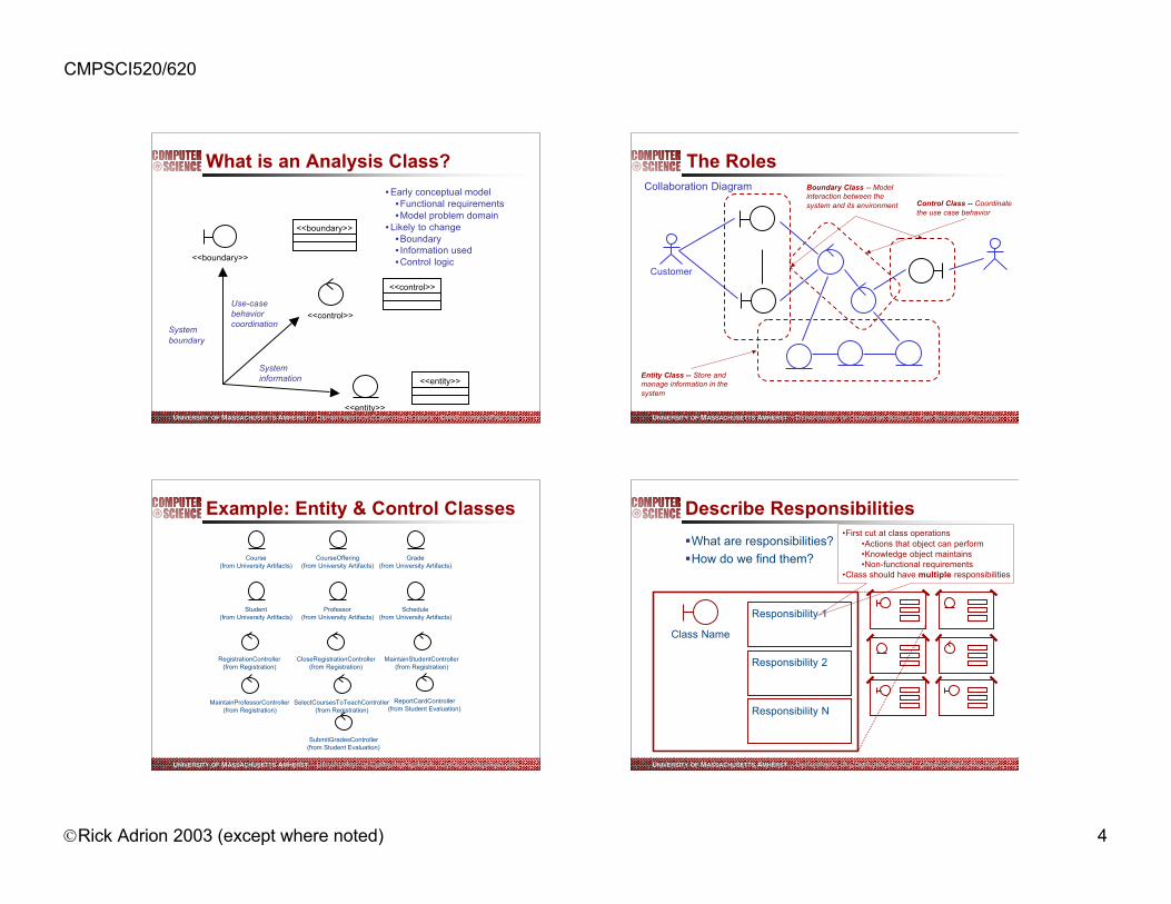
What is an Analysis Class?
<<entity>>
<<boundary>>
<<control>>
<<control>>
<<boundary>>
<<entity>>
Systemboundary
Use-casebehaviorcoordination
Systeminformation
• Early conceptual model•Functional requirements•Model problem domain
• Likely to change•Boundary• Information used•Control logic
UUNIVERSITYNIVERSITY OFOF M MASSACHUSETTS ASSACHUSETTS AAMHERSTMHERST •• D DEPARTMENTEPARTMENT OF OF CCOMPUTER OMPUTER SSCIENCE CIENCE •• CCMPMPSSCI 520/620 CI 520/620 FFALL 2003ALL 2003
The Roles
Customer
Boundary Class -- Modelinteraction between thesystem and its environment
Entity Class -- Store andmanage information in thesystem
Control Class -- Coordinatethe use case behavior
Collaboration Diagram
UUNIVERSITYNIVERSITY OFOF M MASSACHUSETTS ASSACHUSETTS AAMHERSTMHERST •• D DEPARTMENTEPARTMENT OF OF CCOMPUTER OMPUTER SSCIENCE CIENCE •• CCMPMPSSCI 520/620 CI 520/620 FFALL 2003ALL 2003
Example: Entity & Control Classes
Course(from University Artifacts)
CourseOffering(from University Artifacts)
Grade(from University Artifacts)
Student(from University Artifacts)
Professor(from University Artifacts)
Schedule(from University Artifacts)
RegistrationController(from Registration)
SubmitGradesController(from Student Evaluation)
SelectCoursesToTeachController(from Registration)
MaintainProfessorController(from Registration)
MaintainStudentController(from Registration)
ReportCardController(from Student Evaluation)
CloseRegistrationController(from Registration)
UUNIVERSITYNIVERSITY OFOF M MASSACHUSETTS ASSACHUSETTS AAMHERSTMHERST •• D DEPARTMENTEPARTMENT OF OF CCOMPUTER OMPUTER SSCIENCE CIENCE •• CCMPMPSSCI 520/620 CI 520/620 FFALL 2003ALL 2003
Describe Responsibilities
ßWhat are responsibilities?
ßHow do we find them?
Class Name
Responsibility 1
Responsibility 2
Responsibility N
•First cut at class operations•Actions that object can perform•Knowledge object maintains•Non-functional requirements
•Class should have multiple responsibilities

CMPSCI520/620
”Rick Adrion 2003 (except where noted) 5
UUNIVERSITYNIVERSITY OFOF M MASSACHUSETTS ASSACHUSETTS AAMHERSTMHERST •• D DEPARTMENTEPARTMENT OF OF CCOMPUTER OMPUTER SSCIENCE CIENCE •• CCMPMPSSCI 520/620 CI 520/620 FFALL 2003ALL 2003
Class Responsibilities from aCollaboration Diagram
: Student
: MaintainScheduleForm
: RegistrationController
:Schedule
: CourseCatalogSystem
: MainForm
5: // select 4 primary and 2 alternate offerings( )
1: // select maintain schedule( )
3: // get course offerings( )6: // add courses to schedule( )
7: // create with offerings( )
2: // open schedule form( )
4: // get course offerings( )
MaintainScheduleForm
// select 4 primary and 2 alternate offerings()// open ()
<<boundary>>
MainForm
// select maintain schedule()
<<boundary>>
CourseCatalogSystem
// get course offerings()
<<boundary>>
RegistrationController
// add courses to schedule()
<<control>>
Schedule
// create with offerings()
<<entity>>
Register for Courses use case
UUNIVERSITYNIVERSITY OFOF M MASSACHUSETTS ASSACHUSETTS AAMHERSTMHERST •• D DEPARTMENTEPARTMENT OF OF CCOMPUTER OMPUTER SSCIENCE CIENCE •• CCMPMPSSCI 520/620 CI 520/620 FFALL 2003ALL 2003
Class Responsibilities from aSequence Diagram
: Student : MaintainScheduleForm
: RegistrationController
: Schedule : MainForm : CourseCatalogSystem
5: // select 4 primary and 2 alternate offerings( )
6: // add courses to schedule( )
7: // create with offerings( )
1: // select maintain schedule( )
2: // open schedule form( )
3: // get course offerings( )
4: // get course offerings( )
MaintainScheduleForm
// select 4 primary and 2 alternate offerings()// open ()
<<boundary>>
MainForm
// select maintain schedule()
<<boundary>>
CourseCatalogSystem
// get course offerings()
<<boundary>>
RegistrationController
// add courses to schedule()
<<control>>
Schedule
// create with offerings()
<<entity>>
Register for Courses use case
UUNIVERSITYNIVERSITY OFOF M MASSACHUSETTS ASSACHUSETTS AAMHERSTMHERST •• D DEPARTMENTEPARTMENT OF OF CCOMPUTER OMPUTER SSCIENCE CIENCE •• CCMPMPSSCI 520/620 CI 520/620 FFALL 2003ALL 2003
What are Roles?
ßThe “face” that a class plays in the association
Pre-requisites
Instructor
Course
CourseOffering Professor Department
Department head
UUNIVERSITYNIVERSITY OFOF M MASSACHUSETTS ASSACHUSETTS AAMHERSTMHERST •• D DEPARTMENTEPARTMENT OF OF CCOMPUTER OMPUTER SSCIENCE CIENCE •• CCMPMPSSCI 520/620 CI 520/620 FFALL 2003ALL 2003
Example: Finding Relationships
MainForm
// select maintain schedule()
<<boundary>> MaintainScheduleForm
+ // open()+ // select 4 primary and 2 alternate offerings()
<<boundary>>
1 0..11
CourseCatalogSystem
// get course offerings()
<<boundary>>1 0..*
RegistrationController
// add courses to schedule()// get course offerings ()
<<control>>
1
1
Schedule
// create with offerings()
<<entity>>
1
0..1
: Student
: MaintainScheduleForm
: RegistrationController
:Schedule
: CourseCatalogSystem
: MainForm
5: // select 4 primary and 2 alternate offerings( )
1: // select maintain schedule( )
3: // get course offerings( )6: // add courses to schedule( )
7: // create with offerings( )
2: // open schedule form( )
4: // get course offerings( )
• MaintainScheduleForm does notmake any sense outside of thecontext of a particular usesession.
• Only one MaintainScheduleFormcan be active at any one time, ornone may be active
• one controller for each Schedulebeing created (e.g., each Studentregistration session).
• only one CourseCatalogSysteminstance for possibly manyMaintainScheduleForms
• serializes access
• Many MaintainScheduleFormscan be active at one time (fordifferent sessions/students).
legacy system.
View of Participating Classes (VOPC) diagram.

CMPSCI520/620
”Rick Adrion 2003 (except where noted) 6
UUNIVERSITYNIVERSITY OFOF M MASSACHUSETTS ASSACHUSETTS AAMHERSTMHERST •• D DEPARTMENTEPARTMENT OF OF CCOMPUTER OMPUTER SSCIENCE CIENCE •• CCMPMPSSCI 520/620 CI 520/620 FFALL 2003ALL 2003
So Where Are We?
Architect
ArchitecturalAnalysis
ArchitecturalDesign
DescribeConcurrency
DescribeDistribution
Review theArchitecture
DatabaseDesign
Use-CaseAnalysis
SubsystemDesign
ClassDesign
Use-CaseDesign
Review theDesign
Designer
DatabaseDesigner
DesignReviewer
ArchitectureReviewer
UUNIVERSITYNIVERSITY OFOF M MASSACHUSETTS ASSACHUSETTS AAMHERSTMHERST •• D DEPARTMENTEPARTMENT OF OF CCOMPUTER OMPUTER SSCIENCE CIENCE •• CCMPMPSSCI 520/620 CI 520/620 FFALL 2003ALL 2003
Architectural Design Overview
SupplementarySpecifications
Architecture Document
Analysis Classes
Design Model
DesignGuidelines
Glossary
ArchitecturalDesign
Design Model
DesignGuidelines
Classes and Subsystems
UUNIVERSITYNIVERSITY OFOF M MASSACHUSETTS ASSACHUSETTS AAMHERSTMHERST •• D DEPARTMENTEPARTMENT OF OF CCOMPUTER OMPUTER SSCIENCE CIENCE •• CCMPMPSSCI 520/620 CI 520/620 FFALL 2003ALL 2003
Design Classes
In analysis, we had oneapplication with many
different forms …
LogonForm<<boundary>>
CloseRegistrationForm(from Registrar Interface)
<<boundary>>MaintainScheduleForm(from Student Interface)
<<boundary>>
MaintainProfessorForm(from Registrar Interface)
<<boundary>>
MaintainStudentForm(from Registrar Interface)
<<boundary>>
ReportCardForm(from Student Interface)
<<boundary>>
SelectCoursesForm(from Professor Interface)
<<boundary>> SubmitGradesForm(from Professor Interface)
<<boundary>>
MainForm<<boundary>>
1
0..10..1
1
1 0..1
1
0..1
0..1
1
0..1
1
0..1
1
0..1
1
0..10..1
During design, someanalysis classes may
be split, joined,removed, etc.
UUNIVERSITYNIVERSITY OFOF M MASSACHUSETTS ASSACHUSETTS AAMHERSTMHERST •• D DEPARTMENTEPARTMENT OF OF CCOMPUTER OMPUTER SSCIENCE CIENCE •• CCMPMPSSCI 520/620 CI 520/620 FFALL 2003ALL 2003
Design Classes (cont.)
In design, the oneapplication becomes
three applications, eachwith it’s own forms ...
MaintainScheduleForm
(from Student Interface)
<<boundary>>
ReportCardForm
(from Student Interface)
<<boundary>>
MainStudentForm
(from Student Interface)
<<boundary>>
1
0..1
1
0..1
MaintainStudentForm
(from Registrar Interface)
<<boundary>>MaintainProfessorForm
(from Registrar Interface)
<<boundary>>CloseRegistrationForm
(from Registrar Interface)
<<boundary>>
MainRegistrarForm
(from Registrar Interface)
<<boundary>>
1
0..*
1
0..*
1
0..1
(from Professor Interface)
SubmitGradesForm<<boundary>>
SelectCoursesForm
(from Professor Interface)
<<boundary>>
MainProfessorForm
(from Professor Interface)
<<boundary>>
11
0..1 0..1
LogonForm<<boundary>>
CloseRegistrationForm(from Registrar Interface)
<<boundary>>MaintainScheduleForm(from Student Interface)
<<boundary>>
MaintainProfessorForm(from Registrar Interface)
<<boundary>>
MaintainStudentForm(from Registrar Interface)
<<boundary>>
ReportCardForm(from Student Interface)
<<boundary>>
SelectCoursesForm(from Professor Interface)
<<boundary>> SubmitGradesForm(from Professor Interface)
<<boundary>>
MainForm<<boundary>>
1
0..10..1
1
1 0..1
1
0..1
0..1
1
0..1
1
0..1
1
0..1
1
0..10..1

CMPSCI520/620
”Rick Adrion 2003 (except where noted) 7
UUNIVERSITYNIVERSITY OFOF M MASSACHUSETTS ASSACHUSETTS AAMHERSTMHERST •• D DEPARTMENTEPARTMENT OF OF CCOMPUTER OMPUTER SSCIENCE CIENCE •• CCMPMPSSCI 520/620 CI 520/620 FFALL 2003ALL 2003
Class Name
Package Name
Classes & packages
ßWhat is a class?ßA description of a set of objects that share the sameresponsibilities, relationships, operations, attributes, andsemantics.
ßWhat is a package?ßA general purpose mechanism for organizing elementsinto groups
ßA model element which can contain other modelelements
UUNIVERSITYNIVERSITY OFOF M MASSACHUSETTS ASSACHUSETTS AAMHERSTMHERST •• D DEPARTMENTEPARTMENT OF OF CCOMPUTER OMPUTER SSCIENCE CIENCE •• CCMPMPSSCI 520/620 CI 520/620 FFALL 2003ALL 2003
A
<<subsystem>>
PackageB
Class B1
Class B2
Client Class
Encapsulation is the key! But note for packages dependencies should be on public classes
Packages Vs. Subsystems
ßPackages provide nobehaviorßPackages are simply
containers of thingswhich providebehaviorßPackages help
organize and controlsets of classes thatare needed incommon, but whicharen’t reallysubsystemsßDependencies are on
specific elementswithin the Package
ßSubsystems providebehavior, packagesdo not
ßSubsystemscompletelyencapsulatetheir contents
ßDependencies areon the interface ofthe subsystem
ßSubsystems areeasily replaceable
UUNIVERSITYNIVERSITY OFOF M MASSACHUSETTS ASSACHUSETTS AAMHERSTMHERST •• D DEPARTMENTEPARTMENT OF OF CCOMPUTER OMPUTER SSCIENCE CIENCE •• CCMPMPSSCI 520/620 CI 520/620 FFALL 2003ALL 2003
Modeling Design Subsystems
CourseCatalog<<subsystem>>
(from Business Objects)ICourseCatalog
(from CourseCatalog)
FinanceSystem<<subsystem>>
(from Business Services)IFinanceSystem
(from FinanceSystem)
ICourseCatalog
CourseCatalog<<subsystem>>
CourseCatalog<<subsystem>>
<<subsystem>> package =package with a stereotypeof <<subsystem>>
<<subsystem>> proxy class =class with a stereotype of<<subsystem>>
Note: Rose does not fullysupport subsystems
UUNIVERSITYNIVERSITY OFOF M MASSACHUSETTS ASSACHUSETTS AAMHERSTMHERST •• D DEPARTMENTEPARTMENT OF OF CCOMPUTER OMPUTER SSCIENCE CIENCE •• CCMPMPSSCI 520/620 CI 520/620 FFALL 2003ALL 2003
DesignClass
Subsystem<<subsystem>>
DesignClass
DesignClass
DesignClass
Subsystem<<subsystem>>
Subsystem<<subsystem>>
Design Classes and Subsystems
ß Identifying Design Classesßanalysis class is simple and already represents a singlelogical abstraction-> design classßentity classes survive relatively intact into design.
ß Identifying Subsystemsßanalysis class is complex, such that it appears to embodybehaviors that cannot be the responsibility of a single classacting alone, or the responsibilities may need to be reused,the analysis class should be mapped to a subsystemßmay take a few iterations to stabilize.
ßAnalysis classes which evolve intosubsystems might include:ßcomplex services and/or utilitiesßuser interfaces and externalsystem interfaces.

CMPSCI520/620
”Rick Adrion 2003 (except where noted) 8
UUNIVERSITYNIVERSITY OFOF M MASSACHUSETTS ASSACHUSETTS AAMHERSTMHERST •• D DEPARTMENTEPARTMENT OF OF CCOMPUTER OMPUTER SSCIENCE CIENCE •• CCMPMPSSCI 520/620 CI 520/620 FFALL 2003ALL 2003
Design goals
ßProperties of a system which make it flexible,maintainableßAbstraction
ßModularityßCohesionßhow clearly-defined a particular module or procedure isßa module with high cohesion does one or a few things exceedingly well.
ßCouplingßstrength of connections between modules
ßwhat information needs to be communicated between modules
ßGoal: High cohesion, low coupling
ßInformation hiding
ßComplexity
UUNIVERSITYNIVERSITY OFOF M MASSACHUSETTS ASSACHUSETTS AAMHERSTMHERST •• D DEPARTMENTEPARTMENT OF OF CCOMPUTER OMPUTER SSCIENCE CIENCE •• CCMPMPSSCI 520/620 CI 520/620 FFALL 2003ALL 2003
Partitioning Considerationsß Coupling and cohesionß design elements with tight coupling/cohesion (e.g., lots of relationships and
communication) should be should be placed in the same partitionß design elements with loose coupling/cohesion should be placed in separate
partitions.ß User organizationß not a good long-term strategy because the organizational structure may changeß you want the software and the business organization to be independent
ß System distributionß partitioning to reflect distribution can help to visualize the network communication
which will occur as the system executes., but can make the system more difficult tochange if the Deployment Model changes significantly.
ß Secrecy & access controlß functionality requiring special clearance must be partitioned into subsystems that
will be developed independently, with the interfaces to the secrecy areas the onlyvisible aspect of these subsystems.
ß Variabilityß partition “optional” functionality
UUNIVERSITYNIVERSITY OFOF M MASSACHUSETTS ASSACHUSETTS AAMHERSTMHERST •• D DEPARTMENTEPARTMENT OF OF CCOMPUTER OMPUTER SSCIENCE CIENCE •• CCMPMPSSCI 520/620 CI 520/620 FFALL 2003ALL 2003
Typical Layering Approach
Generalfunctionality
Specificfunctionality
UUNIVERSITYNIVERSITY OFOF M MASSACHUSETTS ASSACHUSETTS AAMHERSTMHERST •• D DEPARTMENTEPARTMENT OF OF CCOMPUTER OMPUTER SSCIENCE CIENCE •• CCMPMPSSCI 520/620 CI 520/620 FFALL 2003ALL 2003
Goal is to reduce coupling and to ease maintenance effort
Layering Guidelines
ßVisibilityßDependencies only within currentlayer and below
ßVolatilityßUpper layers affected byrequirements changesßLower layers affected byenvironment changes
ßGeneralityßMore abstract model elements inlower layers
ßNumber of layersßSmall system: 3 layersßComplex system: 5-7 layers
User Interface<<layer>>
Business Services<<layer>>
Business Objects<<layer>>
System<<layer>>
Middleware<<layer>>
java
global
Base Reuse
global

CMPSCI520/620
”Rick Adrion 2003 (except where noted) 9
UUNIVERSITYNIVERSITY OFOF M MASSACHUSETTS ASSACHUSETTS AAMHERSTMHERST •• D DEPARTMENTEPARTMENT OF OF CCOMPUTER OMPUTER SSCIENCE CIENCE •• CCMPMPSSCI 520/620 CI 520/620 FFALL 2003ALL 2003
Layers & Visibility
User Interface<<layer>>
Business Services<<layer>>
Business Objects<<layer>>
System<<layer>>
Middleware<<layer>>
java
global
Base Reuse
global
PackageB
Class B1
Class B2
PackageA
Class A1
Class A3
Class A2A
B
Public visibility
Private visibility
Only publicclasses can be
referenced outsideof the owning
package
UUNIVERSITYNIVERSITY OFOF M MASSACHUSETTS ASSACHUSETTS AAMHERSTMHERST •• D DEPARTMENTEPARTMENT OF OF CCOMPUTER OMPUTER SSCIENCE CIENCE •• CCMPMPSSCI 520/620 CI 520/620 FFALL 2003ALL 2003
Layering
ßConcentrate on encapsulating change
ßPackage dependencies are not transitive, thus one layercan shield another from change
ßUpward dependencies should be resolved in designße.g., call backs can be replaced with the “subscribes to”association whose source is a class (called thesubscriber) and whose target is a class (called thepublisher)ßsubscriber specifies a set of events and is notified when oneof those events occurs in the target
UUNIVERSITYNIVERSITY OFOF M MASSACHUSETTS ASSACHUSETTS AAMHERSTMHERST •• D DEPARTMENTEPARTMENT OF OF CCOMPUTER OMPUTER SSCIENCE CIENCE •• CCMPMPSSCI 520/620 CI 520/620 FFALL 2003ALL 2003
Back to layers
Registrar Interface
GUI Framework
Student Interface
Secure Interfaces
(from Security)
The applications need to retain the current user's context
Professor Interface
SecureUser<<interface>>
+ getUserId( ) : UniqueId
( from Secure Interfaces )
+ getAccess( SecureData ) : SecurityAccess+ setAccess( SecureData, SecurityAccess)
( from GUI Framework )LogonForm
+ open( )
0..1
1
MainApplicationForm
+ start( )
( from GUI Framework )
0..1
1
A bi-directional relationship exists betweenthe GUI Framework and the other interfacepackages because the Logon Form needsto be able to notify the application forms
Window(from java.awt)
View
+ open()+ refresh()+ close()+ update()
1
0..*
1
0..*
inherits frominherits from
inherits from
UUNIVERSITYNIVERSITY OFOF M MASSACHUSETTS ASSACHUSETTS AAMHERSTMHERST •• D DEPARTMENTEPARTMENT OF OF CCOMPUTER OMPUTER SSCIENCE CIENCE •• CCMPMPSSCI 520/620 CI 520/620 FFALL 2003ALL 2003
User Interface Layer: Main Forms
MaintainScheduleForm(from Student Interface)
<<boundary>>
ReportCardForm(from Student Interface)
<<boundary>>
MainStudentForm(from Student Interface)
<<boundary>>
1
0..1
1
0..1
MaintainStudentForm(from Registrar Interface)
<<boundary>>MaintainProfessorForm
(from Registrar Interface)
<<boundary>>CloseRegistrationForm
(from Registrar Interface)
<<boundary>>
MainRegistrarForm(from Registrar Interface)
<<boundary>>
1
0..*
1
0..*
1
0..1 (from Professor Interface)SubmitGradesForm
<<boundary>>SelectCoursesForm
(from Professor Interface)
<<boundary>>
MainProfessorForm(from Professor Interface)
<<boundary>>
11
0..1 0..1
MainApplicationForm
(from GUI Framework)
<<boundary>>LogonForm
(from GUI Framework)1 0..1inherit from the MainApplicationForm
that came from the GUI framework
LogonForm was reverse engineered
From GUI framework
aggregation relationships to be addressed in Class Design

CMPSCI520/620
”Rick Adrion 2003 (except where noted) 10
UUNIVERSITYNIVERSITY OFOF M MASSACHUSETTS ASSACHUSETTS AAMHERSTMHERST •• D DEPARTMENTEPARTMENT OF OF CCOMPUTER OMPUTER SSCIENCE CIENCE •• CCMPMPSSCI 520/620 CI 520/620 FFALL 2003ALL 2003
More Layers
Database(from OODBMS)
Objectstore(from OODBMS)
OODBMSTransaction(from OODBMS)
IPersistent(from OODBMS)
<<Interface>>
sql(from RelationalDBMS)
<<utility>>
RDBMSTransaction(from RelationalDBMS)
RelationalDBMS
OODBMS
Middleware
UniqueId(from Secure Interfaces)
SecurityAccess(from Secure Interfaces)
SecureData
(from Secure Interfaces)
SecureUser
(from Secure Interfaces)
UserSecurityContext(from Security Manager)
SecuritySecure
InterfacesSecurity Manager
<<subsystem>>Contains
2 packages
System
UUNIVERSITYNIVERSITY OFOF M MASSACHUSETTS ASSACHUSETTS AAMHERSTMHERST •• D DEPARTMENTEPARTMENT OF OF CCOMPUTER OMPUTER SSCIENCE CIENCE •• CCMPMPSSCI 520/620 CI 520/620 FFALL 2003ALL 2003
So Where Are We?
Architect
ArchitecturalAnalysis
ArchitecturalDesign
DescribeConcurrency
DescribeDistribution
Review theArchitecture
DatabaseDesign
Use-CaseAnalysis
SubsystemDesign
ClassDesign
Use-CaseDesign
Review theDesign
Designer
DatabaseDesigner
DesignReviewer
ArchitectureReviewer
UUNIVERSITYNIVERSITY OFOF M MASSACHUSETTS ASSACHUSETTS AAMHERSTMHERST •• D DEPARTMENTEPARTMENT OF OF CCOMPUTER OMPUTER SSCIENCE CIENCE •• CCMPMPSSCI 520/620 CI 520/620 FFALL 2003ALL 2003
A look ahead to Use Case Design
ßUse-Case design vs. analysisß in analysis, the classes we discovered are “large” to keep themodel “small” so we can uderstand the interactions (anddiagrams)ß in design, flesh out the class structure (“look inside”) to adddesign elements to implement the publicly visible behaviors,but defer subsystem design to the subsystem designers
ßWe have:ß an initial architectural definitionß defined the major elements of our system (e.g., thesubsystems, their interfaces, the design classes, theprocesses and threads) and their relationships, and we havean understanding of how these elements map into thehardware on which the system will run.
ß In Use Case Design, concentrate on how a use case has beenimplemented and make sure that there is consistency frombeginning to end, and that nothing has been missed
tend to alternate between Subsystem Design, Class Design and Use Case Design
UUNIVERSITYNIVERSITY OFOF M MASSACHUSETTS ASSACHUSETTS AAMHERSTMHERST •• D DEPARTMENTEPARTMENT OF OF CCOMPUTER OMPUTER SSCIENCE CIENCE •• CCMPMPSSCI 520/620 CI 520/620 FFALL 2003ALL 2003
Use Case Design Overview
Use Case Realization
Use-CaseDesign
SupplementarySpecifications
Use-Case Model
Use-Case Realization
Design Subsystems and Interfaces
Design Classes
Use-Case Realizations,described withsequence diagrams

CMPSCI520/620
”Rick Adrion 2003 (except where noted) 11
UUNIVERSITYNIVERSITY OFOF M MASSACHUSETTS ASSACHUSETTS AAMHERSTMHERST •• D DEPARTMENTEPARTMENT OF OF CCOMPUTER OMPUTER SSCIENCE CIENCE •• CCMPMPSSCI 520/620 CI 520/620 FFALL 2003ALL 2003
Use Case Realization
Use Case Use Case Realization
<<realizes>>
Class Diagrams
Sequence Diagrams Collaboration Diagrams
Use Case RealizationDocumentation
Use Case Model Design Model
redraw diagrams•sub system interfaces•refined classes, objects
UUNIVERSITYNIVERSITY OFOF M MASSACHUSETTS ASSACHUSETTS AAMHERSTMHERST •• D DEPARTMENTEPARTMENT OF OF CCOMPUTER OMPUTER SSCIENCE CIENCE •• CCMPMPSSCI 520/620 CI 520/620 FFALL 2003ALL 2003
Encapsulating Subsystem Interactions
ßSubsystems should be represented by their interfaceson interaction diagrams
ßMessages to subsystems are modeled as messages tothe subsystem interface
ßMessages to subsystems correspond to operations ofthe subsystem interface
ßInteractions within subsystems modeled in SubsystemDesign
<<subsystem>>MySubsystem
InterfaceA
op1()
Op1()
:InterfaceA
UUNIVERSITYNIVERSITY OFOF M MASSACHUSETTS ASSACHUSETTS AAMHERSTMHERST •• D DEPARTMENTEPARTMENT OF OF CCOMPUTER OMPUTER SSCIENCE CIENCE •• CCMPMPSSCI 520/620 CI 520/620 FFALL 2003ALL 2003
Advantages of Encapsulation
ßUse-case realizations are less cluttered
ßUse-case realizations can be created before the internaldesigns of subsystems are created
ßUse-case realizations are more generic and easy tochange
ßSupports parallel subsystem development
Raises the level of abstraction
UUNIVERSITYNIVERSITY OFOF M MASSACHUSETTS ASSACHUSETTS AAMHERSTMHERST •• D DEPARTMENTEPARTMENT OF OF CCOMPUTER OMPUTER SSCIENCE CIENCE •• CCMPMPSSCI 520/620 CI 520/620 FFALL 2003ALL 2003
Design Element Interactions (Login)
: MainStudentForm : Student
1: start( )
: LogonForm
2: open()
3: enterUserName( )
4: enterPassword( )
5: logInUser( )
: SecureUser
[ Login was successful ]
6: validateUserIDPassword( )
8: new(UserID)
7: setupUserContext( )
10: getUserContext( )
11: close( )
[ Login was successful ]9: setupUserContext( )
SecureUser
+ setAccess()+ getAccess()+ getUserId()+ new()
(from Secure Interfaces)
<<Interface>>
1
0..1
MainStudentForm
+ registerForCourses()+ viewReportCard()
(from Student Interface)
<<boundary>>
LogonForm
(from GUI Framework)MainApplicationForm
(from GUI Framework)
<<boundary>>0..11
inherits from
exists an object whose classrealizes the SecureUser interface& manages information about the current user’s access to securedata without directly depending on the classes
composition
CMPSCI520/620
”Rick Adrion 2003 (except where noted) 12
UUNIVERSITYNIVERSITY OFOF M MASSACHUSETTS ASSACHUSETTS AAMHERSTMHERST •• D DEPARTMENTEPARTMENT OF OF CCOMPUTER OMPUTER SSCIENCE CIENCE •• CCMPMPSSCI 520/620 CI 520/620 FFALL 2003ALL 2003
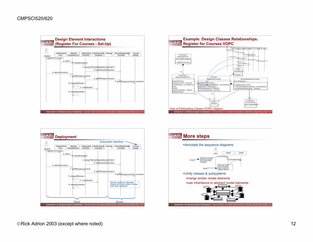
Design Element Interactions(Register For Courses - Set-Up)
Give current user context wide open access
No Conflict
: RemoteRegistrationController
: MainStudentForm
: MaintainScheduleForm
: RegistrationController
: NamingClientSchedule : Schedule : Student
2: open( )3: new(SecureUser)
5: setSession(SecureUser)
4: lookup("RemoteRegistrationController")
1: registerForCourses( )
6: selectCurriculum( )
7: getOfferings(curriculum)
8: getOfferings(curriculum)
10: displayOfferings( )
11: new(Student)
: ICourseCatalog
9: getOfferings(curriculum, semester)
12: displaySchedule()
UUNIVERSITYNIVERSITY OFOF M MASSACHUSETTS ASSACHUSETTS AAMHERSTMHERST •• D DEPARTMENTEPARTMENT OF OF CCOMPUTER OMPUTER SSCIENCE CIENCE •• CCMPMPSSCI 520/620 CI 520/620 FFALL 2003ALL 2003
Example: Design Classes Relationships:Register for Courses VOPC
MainStudentForm
+ registerForCourses()
(from Student Interface)
<<boundary>>
ICourseCatalog
(from CourseCatalog)
<<Interface>>
RemoteRegistrationController
+ getOfferings(curriculum)+ notifyOfferingSelection(offering : CourseOffering)+ saveSchedule(theSchedule : Schedule)
(from Registration)
1
1
Naming
+ lookup()
(from java.rmi)
RegistrationController
getOfferings(curriculum)notifyOfferingSelection(offering : CourseOffering)new(context : SecureUser)saveSchedule(sched : Schedule)cancelSchedule(sched : Schedule)
<<control>>
1
1
Schedule<<entity>>
1
0..1
MaintainScheduleForm
displayOfferings()selectCurriculum() : CurriculumselectOffering() : CourseOfferingsave()cancel()update(changedItem : ISubject)displaySchedule()
<<boundary>>
1 1
0..1
1
0..1
0..1
View of Participating Classes (VOPC) diagram.
: RemoteRegistrationController
: MainStudentForm
: MaintainScheduleForm
: RegistrationController
: NamingClientSchedule : Schedule : Student
2: open( )3: new(SecureUser)
5: setSession(SecureUser)
4: lookup("RemoteRegistrationController")
1: registerForCourses( )
6: selectCurriculum( )
7: getOfferings(curriculum)
8: getOfferings(curriculum)
10: displayOfferings( )
11: new(Student)
: ICourseCatalog
9: getOfferings(curriculum, semester)
12: displaySchedule()
UUNIVERSITYNIVERSITY OFOF M MASSACHUSETTS ASSACHUSETTS AAMHERSTMHERST •• D DEPARTMENTEPARTMENT OF OF CCOMPUTER OMPUTER SSCIENCE CIENCE •• CCMPMPSSCI 520/620 CI 520/620 FFALL 2003ALL 2003
Deployment
Works similar to Observer. Cache will notify when Course has been retrieved
Give current user context wide open access
No Conflict
: RemoteRegistrationController
: MainStudentForm
: MaintainScheduleForm
: RegistrationController
: NamingClientSchedule : Schedule : Student
2: open( )3: new(SecureUser)
5: setSession(SecureUser)
4: lookup("RemoteRegistrationController")
1: registerForCourses( )
6: selectCurriculum( )
7: getOfferings(curriculum)
8: getOfferings(curriculum)
10: displayOfferings( )
11: new(Student)
: ICourseCatalog
9: getOfferings(curriculum, semester)
12: displaySchedule()
Subsystem Interface
Client ServerUUNIVERSITYNIVERSITY OFOF M MASSACHUSETTS ASSACHUSETTS AAMHERSTMHERST •• D DEPARTMENTEPARTMENT OF OF CCOMPUTER OMPUTER SSCIENCE CIENCE •• CCMPMPSSCI 520/620 CI 520/620 FFALL 2003ALL 2003
More steps
ßAnnotate the sequence diagrams
ßUnify classes & subsystemsßmerge similar model elements
ßuse inheritance to abstract model elements
: Actor1 : ClassA : ClassB
1: Do Something
2: Do Something MoreScripts can be used to describe the details surrounding these messages.
Notes can include more information about a particular diagram element
Script
Note

CMPSCI520/620
”Rick Adrion 2003 (except where noted) 13
UUNIVERSITYNIVERSITY OFOF M MASSACHUSETTS ASSACHUSETTS AAMHERSTMHERST •• D DEPARTMENTEPARTMENT OF OF CCOMPUTER OMPUTER SSCIENCE CIENCE •• CCMPMPSSCI 520/620 CI 520/620 FFALL 2003ALL 2003
So Where Are We?
Architect
ArchitecturalAnalysis
ArchitecturalDesign
DescribeConcurrency
DescribeDistribution
Review theArchitecture
DatabaseDesign
Use-CaseAnalysis
SubsystemDesign
ClassDesign
Use-CaseDesign
Review theDesign
Designer
DatabaseDesigner
DesignReviewer
ArchitectureReviewer
UUNIVERSITYNIVERSITY OFOF M MASSACHUSETTS ASSACHUSETTS AAMHERSTMHERST •• D DEPARTMENTEPARTMENT OF OF CCOMPUTER OMPUTER SSCIENCE CIENCE •• CCMPMPSSCI 520/620 CI 520/620 FFALL 2003ALL 2003
Subsystem Design Overview
Use-Case Realization
Design Subsystems and Interfaces
SubsystemDesign
Use Case Realization
Design Subsystems and Interfaces
Design Classes
UUNIVERSITYNIVERSITY OFOF M MASSACHUSETTS ASSACHUSETTS AAMHERSTMHERST •• D DEPARTMENTEPARTMENT OF OF CCOMPUTER OMPUTER SSCIENCE CIENCE •• CCMPMPSSCI 520/620 CI 520/620 FFALL 2003ALL 2003
Subsystem design
ßwe haveßdefined the subsystems, their interfaces, and theirdependencies
ßmade an initial cut at some design classes, which have beenallocated to subsystems
ß identified components or subsystems: “containers” of complexbehavior that, for simplicity, we treat as a ‘black box’.
ß in Subsystem Design, we look atßresponsibilities of the subsystems in detail
ßdefining and refining the classes that are needed to implementthose responsibilities
ßrefining subsystem dependencies, as needed
ß internal interactions are expressed as collaborations ofclasses and possibly other components or subsystems
UUNIVERSITYNIVERSITY OFOF M MASSACHUSETTS ASSACHUSETTS AAMHERSTMHERST •• D DEPARTMENTEPARTMENT OF OF CCOMPUTER OMPUTER SSCIENCE CIENCE •• CCMPMPSSCI 520/620 CI 520/620 FFALL 2003ALL 2003
Interface and Subsystem
ßWhat is an interface?ßa model element which defines a set of behaviors (a setof operations) offered by a classifier model element(specifically, a class, subsystem or component)
ßWhat is a subsystem?ßContains other model elements and has behavior
ßRealizes one or more interfaces
<<subsystem>>Finance System
FinancialTransaction
FinancialTransaction<<Interface>>
realizes<<subsystem>>Finance System
Recall: packages provide no behavior; they are simply containers of things whichprovide behavior

CMPSCI520/620
”Rick Adrion 2003 (except where noted) 14
UUNIVERSITYNIVERSITY OFOF M MASSACHUSETTS ASSACHUSETTS AAMHERSTMHERST •• D DEPARTMENTEPARTMENT OF OF CCOMPUTER OMPUTER SSCIENCE CIENCE •• CCMPMPSSCI 520/620 CI 520/620 FFALL 2003ALL 2003
Distribute Subsystem Responsibilities
ßIdentify or reuse existing classes and/or subsystems
ßAllocate subsystem responsibilities to classes and/orsubsystems
ßIncorporate the applicable mechanisms (e.g.,persistence, distribution, etc.)
ßDocument collaborations with “interface realization”diagramsß1 or more sequence diagrams per interface operation
ßRevisit Architectural DesignßAdjust subsystem boundaries and/or dependencies, asneeded
UUNIVERSITYNIVERSITY OFOF M MASSACHUSETTS ASSACHUSETTS AAMHERSTMHERST •• D DEPARTMENTEPARTMENT OF OF CCOMPUTER OMPUTER SSCIENCE CIENCE •• CCMPMPSSCI 520/620 CI 520/620 FFALL 2003ALL 2003
Subsystem design
: RemoteRegistrationController
: MainStudentForm
: MaintainScheduleForm
: RegistrationController
: NamingClientSchedule : Schedule : Student
2: open( )3: new(SecureUser)
5: setSession(SecureUser)
4: lookup("RemoteRegistrationController")
1: registerForCourses( )
6: selectCurriculum( )
7: getOfferings(curriculum)
8: getOfferings(curriculum)
10: displayOfferings( )
11: new(Student)
: ICourseCatalog
9: getOfferings(curriculum, semester)
12: displaySchedule()
Subsystem Interface
Client Server
Flesh out
UUNIVERSITYNIVERSITY OFOF M MASSACHUSETTS ASSACHUSETTS AAMHERSTMHERST •• D DEPARTMENTEPARTMENT OF OF CCOMPUTER OMPUTER SSCIENCE CIENCE •• CCMPMPSSCI 520/620 CI 520/620 FFALL 2003ALL 2003
Local Subsystem Interaction:CourseOfferingList
Do until fetch returns NotFound status
The string represents some criteria. Sometimes a more robust solution with a query object is used.
Get attribute values from raw data
: CourseOffering
CourseCatalogClient
: CourseCatalog : DBCourseOffering
: RDBMSTransaction : sql
1: getCourseOfferings(string)
5: getCourseOfferings(string)
9: parseResults( )
10: new(offeringId, number, startTime, endTime, days, courseId)
2: new
3: start( )4: startTrans( )
6: bind()
7: execsql(String)
8: fetch( )
11: add (CourseOffering)
12: commit()13: entTrans( )
6: new()
CourseCatalog Interaction•“looks inside” the subsystem•one or more per subsystem
RDBMSRetrieve
untyped object becausewe don’t care who theclient is.
See Maciaszek - notime to discuss DBdesign
UUNIVERSITYNIVERSITY OFOF M MASSACHUSETTS ASSACHUSETTS AAMHERSTMHERST •• D DEPARTMENTEPARTMENT OF OF CCOMPUTER OMPUTER SSCIENCE CIENCE •• CCMPMPSSCI 520/620 CI 520/620 FFALL 2003ALL 2003
Document Subsystem Elements
CourseCatalog
+ getOfferings()
<<subsystem>>
sql
+ bind()+ execsql()+ startTrans()+ commit()+ fetch()+ endTrans()
(from RelationalDBMS)
<<utility>>
RDBMSTransaction
+ start()+ commit()+ rollback()+ new()
(from RelationalDBMS)
DBCourseOffering
+ getCourseOfferings()+ parseResults()11
CourseOffering
+ getCourseId()+ addStudent()+ new()+ getNumber()+ getStartTime()+ getEndTime()+ getDays()+ getNumStudents()+ removeStudent()+ update()
(from University Artifacts)
<<entity>>0..*
1
0..*
CourseOfferingList
+ new()+ add()
(from University Artifacts)
List(from Base Reuse)
<CourseOffering><<bind>>
ICourseCatalog
1
0..*
create one or more classdiagrams showing theelements contained by thesubsystem, and theirassociations with oneanother
A state diagram may beneeded to document thepossible states thesubsystem can assume

CMPSCI520/620
”Rick Adrion 2003 (except where noted) 15
UUNIVERSITYNIVERSITY OFOF M MASSACHUSETTS ASSACHUSETTS AAMHERSTMHERST •• D DEPARTMENTEPARTMENT OF OF CCOMPUTER OMPUTER SSCIENCE CIENCE •• CCMPMPSSCI 520/620 CI 520/620 FFALL 2003ALL 2003
Client Support<<subsystem>>
Server Support<<subsystem>>
Moreflexible
Server
Client Support<<subsystem>>
Server Support<<subsystem>>
Server<<Interface>>Client
(from Client Support)
Describe Subsystem Dependencies
ßSubsystem layering using direct dependency
ßSubsystem layering using interface dependency
Notrecommended
UUNIVERSITYNIVERSITY OFOF M MASSACHUSETTS ASSACHUSETTS AAMHERSTMHERST •• D DEPARTMENTEPARTMENT OF OF CCOMPUTER OMPUTER SSCIENCE CIENCE •• CCMPMPSSCI 520/620 CI 520/620 FFALL 2003ALL 2003
Describe Subsystem Dependencies
ICourseCatalogRegistration CourseCatalog
<<subsystem>>
University Artifacts
RelationalDBMS