209100 hudy setup book - PETITRCsite.petitrc.com/Tech/Handbooks/HudySetupBook.pdfIn this manual we...
52
Transcript of 209100 hudy setup book - PETITRCsite.petitrc.com/Tech/Handbooks/HudySetupBook.pdfIn this manual we...


2
778
CONTENTS
4 7
9 9
HUDY ALL-IN-ONE SET-UP SOLUTION Solution Components for 1/10 Touring Cars Assembling and Installing the Set-Up Stands Assembling the Set-Up Stands Assembling the Set-Up Board Installing the Set-Up Stands Overview of Car Set-Up Set-Up Order Downstops & Droop Measuring Downstops Adjusting Downstops
Measuring Droop Adjusting Droop
Ride Height Measuring Ride Height Adjusting Ride Height
Track-Width 13
Measuring Track-Width Using the Set-Up Board Decal
Adjusting Track-Width – Pivotball Suspension
Adjusting Track-Width – C-hub Suspension Camber & Camber Rise 1
Measuring Camber
Adjusting Camber – Pivotball Suspension
Adjusting Camber – C-Hub Suspension
Camber Rise Caster 18
Measuring Front Caster
Adjusting Front Caster – Pivotball Suspension
Adjusting Front Caster – C-Hub Suspension Toe
Measuring Toe Adjusting Toe – Pivotball Suspension Adjusting Toe – C-Hub Suspension
Steering Throw SymmetryMeasuring and Adjusting Steering Throw Symmetry
TweakMeasuring Tweak Combating Tweak Adjusting Tweak Using Spring Preload
MaintenanceSummary
10 10 11 11 12 12 12 13
14
15
15
16
16
17
17
18
18
19
19
19
20
20
21
21
22
23
23
24
25
27
27
28 28 30
35
36
SET-UP THEORY Basic Terminology Weight Transfer Roll Center Roll Center Basics Determining Roll Center Location Roll Center in Action Effects of Front Roll Center Adjustment Effects of Rear Roll Center Adjustment Adjusting Roll Center Downstops Effects of Downstop Adjustment Adjusting Downstops Ride Height Effects of Ride Height Adjustment Adjusting Ride Height
30 30 31 31 31 32
35 35
36 36
2

3
Droop 36
ToeEffects of Toe Adjustment Adjusting Toe
Upstops Effects of Upstop Adjustment Adjusting Upstops
Anti-Dive (Front) Effects of Front Anti-Dive Adjustment Adjusting Anti-Dive
Anti-Squat (Rear) Effects of Rear Anti-Squat Adjustment Adjusting Anti-Squat
Wheelbase Effects of Wheelbase Adjustment Adjusting Wheelbase
Anti-Roll Bars Front Anti-Roll Bar Rear Anti-Roll Bar Adjusting Anti-Roll Bars
Front and Rear Axles Solid Axles Gear Differentials
Effects of Droop Adjustment 37 Maintaining Droop Value 37 Adjusting Droop 37
Shock Absorbers 37 Springs 38 Spring Preload 38 Shock Position 39 Shock Damping 40
Track-Width 41 Effects of Track-Width Adjustment 41 Adjusting Track-Width 41
Camber 41 Adjusting Camber 41
Caster 42 Effects of Caster Adjustment 42 Adjusting Caster 43
43 44 44
44 44 44
44 45 45
45 45 45
46 46 46
47 47 47 47
48 48 48
SET-UP QUICK REFERENCE How To Use the Quick Reference Table 49 Identify the Problem 49 Using the Table 49 Test the Solution 49 Quick Reference Table 50

SOLUTION COMPONENTS FOR 1/10 TOURING CARS
The HUDY All-In-One Set-Up Solution for 1/10 Touring Cars includes the following top-quality components:
109305 Universal Exclusive Alu. Set-Up System for Touring Cars
• CNC-machined alu. and acrylic components• fully ball-bearing equipped• precision engraving• directly measures camber, camber rise, caster, toe, steering throw symmetry easy ‘one-screw’ assembly/disassembly.
107904 HUDY Quick-Tweak Station
• best-in-class solution for quick & easy tweak adjustment • innovative, easy-to-use, high-tech design • fully ball-bearing equipped for smoothness and high precision. • ultra-sensitive balance platform gives
highly-accurate readings, allowing you to quickly & easily read and interpret
tweak.
107702 Droop Gauge Support Blocks
• CNC-machined high-grade aluminum • precision engraving • supports chassis when checking downstops • used with 107712 Droop Gauge or 107714 Ultra-Fine Droop Gauge
107712 Droop Gauge
• CNC-machined high-grade aluminum• precision engraving• measures downstops when used with 107702 Droop Gauge Support Blocks
107716 Ultra-Fine Ride Height Gauge
• CNC-machined high-grade aluminum• precision engraving• measures ride height
For more information on each of these components, see the HUDY website at www.hudy.net
4
107702 Droop Gauge Support Blocksmeasures downstops when used with • super-precise increments of 0.2mm• for more precise adjustment of droop•
107714 Ultra-Fine Droop Gauge

5
perfect set-up adjustment• • precise set-up wheels of the same size
used for tweak correction •
109370 Alu Set-Up Wheels
surfacetough, smooth, liquid-resistant plastic •
for adjustment of 1/10 touring carsaccurate, clear markings with 1mm grid •
Set-Up Board self-adhesive set-up decal for 108201 •
108211 Set-Up Board Decal
for chassis set-upprovides perfectly flat reference surface • very small, compact size• exceptionally flat, warp-resistant surface• suitable for 1/10 R/C touring cars•
108201 Set-Up Board

6
HUDY ALL-IN-ONE SET-UP SOLUTION
Congratulations on choosing the HUDY ALL-IN-ONE SET-UP SOLUTION. This innovative set of expertly designed and crafted tools will provide you with everything you need to tune and set up your R/C car for maximum performance.
R/C car set-up systems were originally designed and developed by Dipl. Eng. Hudy Juraj to enable R/C drivers to set up their cars for high performance. After huge successes with their original set-up systems, HUDY once again proves itself the leader in professional tool development by creating innovative, original, and revolutionary R/C solutions with this completely new, integrated, ALL-IN-ONE SETUP SOLUTION. Combining a wealth of set-up knowledge and expertly crafted tools, the ALL-IN-ONE SETUP SOLUTION takes all the guesswork out of setting up an R/C car.
The easy-to-use HUDY ALL-IN-ONE-SETUP SOLUTION takes you quickly and intuitively through setting up your R/C car. Even with extensive knowledge of your car and the theories of handling and suspension dynamics, it is sometimes easy to become confused because of the inherent complexity of car set-up. With the HUDY ALL-IN ONE-SETUP SOLUTION we bring you powerful, easy-to-use new tools and knowledge to take the effort and confusion out of car set-up. Follow this guide step by step, and let it educate you as you go through the process of setting up your R/C car.
The solid construction and innovative features of the HUDY All-In-One Set-Up Solution give you instant, accurate, and reproducible readings. No more imprecise eyeballing of settings, no more inaccurate guessing, just consistent and precise settings like the world’s top drivers use.
There are several types of suspensions used on R/C cars, such as pivotball and C-hub suspensions. Each suspension type has its own way of making adjustments to car settings such as downstops, camber, caster, toe, etc. For detailed information on adjusting the settings on your car, refer to the appropriate set-up manuals for your car.
Adjustments & MeasurementsThe HUDY All-In-One Set-Up Solution can be used for the adjustment and measurement of the following:• downstops• track-width• ride height• camber & camber rise• caster• toe• steering throw symmetry• tweak
Main Features of the HUDY All-In-One Set-Up Solution:• the scientific approach to chassis tuning• quick and straight-forward ‘one screw’ assembly/disassembly• backlash-free, wobble-free mounting• fully ball-bearing equipped set-up stands (12 high-precision ball-bearings)• ultra-smooth, ultra-precise movement and operation• CNC-machined high-grade aluminum stands are hardcoated for increased durability• CNC-machined toe/steering plate made from tough acrylic plastic• all components have precision engraving for instant, reliable readings• carrying box with foam inserts for smart and safe storage and transportation• unmatched value and long life• world famous and prestigious Hudy luxurious design and smart innovative solution
SET-UP THEORY The Set-Up Theory section starting on page 28 describes the effect of making set-up changes on your R/C car.
In this manual we depict the XRAY T4 luxury electric touring car and XRAY NT1 nitro touring car. Most nitro touring cars use pivotball suspension, while most electric touring cars use C-hub suspension. Some of the settings and adjustments described in this manual may not be the same as for your own touring car. You should always refer to your car’s instruction manual and set-up manual for more information about making setup changes.

7
ASSEMBLING AND INSTALLING THE SET-UP STANDS
When you are measuring and adjusting track-width, camber & camber rise, caster, toe, steering throw symmetry, you will need to assemble and install the set-up stands.
When you are measuring tweak, downstops and ride height, you do not need to use the set-up stands.
• • •
1. Attach a camber gauge to a side plate using alu nuts through the ball-bearing at the top of the camber gauge.
2. Tighten the alu nuts until snug.
3. Make sure the stand operates freely without binding.
ASSEMBLING THE SET-UP BOARD
The completed set-up board consists of the Set-Up Board and the Set-Up Board Decal.
IMPORTANT:You should always use only the HUDY set-up board when setting up your car with the HUDY All-In-One Set-Up Solution. This exceptionally flat, warp-free board will ensure accurate, precise measurements.
1. Clean the board with a soft cloth to remove any debris or contaminants.
ASSEMBLING THE SET-UP STANDS The set-up stands of the HUDY All-In-One Set-Up Solution must be assembled in order for you to use them. These stands were designed for quick and easy “one screw” assembly and disassembly
The set-up stands consist of the following pieces:
alloy side plates (4) alloy camber gauges (4) acrylic toe gauge (1)
alu nuts (4) •

8
2. Remove the paper from the rear of the decal, exposing the adhesive backing.
3. Center the decal on the board, and then press the entire decal firmly onto the board.
4. Rub the decal until it is flat and completely adhered to the board.
INSTALLING THE SET-UP STANDS
After you have assembled the four set-up stands, mount them to your car as follows (remember that the car should equipped with all electronics, including the battery).
1. Remove the wheels from the car.
2. In place of the wheels, mount a set-up stand on each of the four axles.
The camber gauge of each stand should face outward so it is easy to read. The camber gauge of the front stand should face forward, while the camber gauge of the rear stand should face rearward.
4. Place the car (with the mounted set-up stands) on the set-up board.
front
rear
3. Attach the set-up stand to the axle using wheel nuts or alu nuts.

9
OVERVIEW OF CAR SET-UP
When setting up your car, use the components of the Hudy All-In-One Set-Up Solution as follows.
To measure/adjust Use
Downstops
Ride height
Droop
Track-width
· Droop Gauge Support Blocks · Droop Gauge
· Ride Height Gauge
· Small ruler
·
For quick track-width checking with wheels mounted, use the set-up board decal.
Camber & camber rise · Assembled set-up stands
Caster
Toe
Steering throw symmetry
Tweak
· Assembled set-up stands
· Assembled set-up stands · Toe gauge
· Assembled set-up stands · Toe gauge
· Alu wheels · Tweak station
See page
10
12
10
13
16
18
19
21
23
There are several types of suspensions used on R/C cars, such as pivotball and C-hub suspensions. Each suspension type has its own way of making adjustments to car settings such as downstops, camber, caster, toe, etc. For detailed information on adjusting the settings on your car, refer to the appropriate set-up manuals for your car.
When setting up your car, you should always prepare the car so it is ready to run, though without the body. This means you should install all electronics, batteries, and fill the fuel tank (nitro only).
SET-UP ORDER
We recommend setting up your car in the order indicated in the table below. The order of the settings has been determined as the most logical to set up your car properly and easily. Also, certain settings must be made before others, as changing one setting will impact another setting.
The table below gives you a breakdown of what components need to be attached on the car, and what you will need to measure the setting.
CAR SET-UP COMPONENTS
Shocks Anti-Roll
Bars Wheels Gauges
Set-Up Stands Blocks &
Droop Height Gauge
Ride
GaugeToe
StationTweak
Ruler Set-UpBoardDecal
Downstops attach doesn’t remove use matter
Ride Height attach attach attach use
Droop attach attach attach use
Track-width attach doesn’t attach use matter
Camber RiseCamber & attach doesn’t
matter remove use
Caster attach doesn’t remove use matter
Toe attach doesn’t remove use use matter
Steering Throw attach doesn’t remove use use Symmetry matter
useuse wheels't don
use/ alu attachTweak

10
1.1 DOWNSTOPS & DROOP
Downstops limit how far the wishbones travel downward (which determines how far upwards the chassis travels). Make sure you adjust downstops so they are equal on both left and right sides.
For detailed information on adjusting the downstops of your car, refer to the appropriate set-up manuals for your car.
INITIAL STEPS SET-UP COMPONENTS:
Prepare the car as follows: Use the following set-up components:
• Wheels: Remove all wheels. • Droop Gauge Support Blocks • Droop Gauge
MEASURING DOWNSTOPS
1. Place the droop gauge support blocks on the set-up board, and then place the chassis on the support blocks.
Make sure the chassis is solidly mounted on the support blocks so it does not move.
2. Check if the suspension is working smoothly.
4. Adjust the front or rear downstops to the desired settings.
3. Using the droop gauge, measure the downstop value.
FRONT DOWNSTOPS:Pivot ball suspension: Measure at the bottom of the front steering blocks. C-hub suspension: Measure at the bottom of the arm
REAR DOWNSTOPS:Pivot ball suspension: Measure at the bottom of the rear upright. C-hub suspension: Measure at the bottom of the arm
POSITIVE numbers indicate the distance (in mm) ABOVE the level of the support blocks (or, above the bottom of the chassis). NEGATIVE numbers indicate the distance (in mm) BELOW the level of the support blocks (or, below the bottom of the chassis).
t
\\§&
HUH.niVi
»ii i r nVi
&
V
nMIUJJPYÿ
»> V t.
Mew
DOWNSTOPS

11
downstop adjustment is the same for front and rear.
Turn OUT the downstop screw so the lower arm DROPS slightly.
ADJUSTING DOWNSTOPS
Increase Turn IN the downstop screw so the lower arm RISES slightly
Decrease
|w
m
•
Wheels: Attach all wheels. It is important that both left & right wheels (at either front or rear of car)
are the same diameter.
anti-roll bars.Anti-roll bars: Attach front & rear•
DROOP
Droop is sometimes interchanged with downstop. This is correct and incorrect. Droop refers to the amount that the chassis travels downward after the car is dropped and the wheels touch the ground; it is also the amount that the chassis travels upward before the wheels lift from the ground.
Droop is in large part affected by the downstop setting, but is also affected by ride height adjustment. • A higher downstop setting creates a smaller gap between the downstop setscrew and
the chassis at rest. This smaller gap reduces the amount that the chassis rises before the wheels lift from the ground. The result is a smaller droop value.
• A lower downstop setting creates a larger gap between the downstop setscrew and the chassis at rest. This larger gap increases the amount that the chassis rises before the wheels lift from the ground. The result is a larger droop value.
INITIAL STEPS SET-UP COMPONENTS:
Prepare the car as follows: Use the following set-up components:
• Shocks: Attach front & rear shocks. • Small Ruler
MEASURING DROOP Measure droop with the car ready-to-run. 1. Place the car on the set-up board.
2. Push down & release the front and rear of the car a few times so that the suspension settles.
3. Place the ruler vertically beside the end of the chassis, so that you can see how much distance there is between the flat surface and the bottom of the chassis.
V \
w 4. Keeping the ruler in place, slowly lift the chassis at its centerline. The chassis rises slightly until the wheels just lift from the set-up board.
5. On the ruler, note the distance to the chassis bottom. The amount that the chassis rose before the wheels lifted is the droop value.
6. Repeat steps 3-5 for the other end of the car.
7. Adjust the front or rear downstops to change the droop of the desired settings.

12
O.uiusi
ADJUSTING DROOP You adjust droop by adjusting downstops. To increase the droop value, decrease the downstop setting. To decrease the droop value, increase the downstop setting. For more information on downstops, see “Downstops” on page 10.
Droop is also affected by ride height changes. For more information on ride height, see “Ride Height” on page 12.
«t-3a"
l
INITIAL STEPS
Prepare the car as follows:
• Shocks: Attach front & rear shocks. • Anti-roll bars: Attach front & rear anti-roll bars. • Wheels: Attach the wheels.
It is important that both left & right wheels (at either front or rear of car) are the same diameter.
MEASURING RIDE HEIGHT
1. Place the car on the set-up board.
2. Push down & release the front and rear of the car a few times so that the suspension settles.
3. Measure the ride height using the ride height gauge at the front and rear of the car at the lowest points of the chassis.
>f
1
A £?&KvSA»-
4. Adjust the front and rear ride height to the desired settings.
Ride Height Gauge•
Use the following set-up components:
SET-UP COMPONENTS:
set-up manuals for your car.For detailed information on adjusting the ride height of your car, refer to the appropriate
screws.Adjust ride height using spring preload only. DO NOT adjust ride height using downstop
without the body.surface on which the car is sitting. Adjust ride height with the car ready-to-run but Ride height is the distance between the bottom of the chassis and the reference
reartide heighrntor ftide heighr
RIDE HEIGHT1.2

13
Ride height adjustment is the same for front and rear.
Increase INCREASE preload on both springs, on left and right side EQUALLY.
I Decrease DECREASE preload on both springs, on left and right side EQUALLY.
ADJUSTMENT RIDE HEIGHT
spring.Use THINNER spaces above
the shock body.Decrease LOOSEN collar so it moves UP
spring.Use THICKER spacers above
DOWN the shock body.Increase TIGHTEN collar so it moves
Preload setting Threaded preload collar Preload spacers
Your car may use threaded spring preload collars or preload spacers.DO NOT adjust ride height using downstop screws.Adjust ride height using spring preload only.
ADJUSTING RIDE HEIGHT
5X
a
inII
A
1.3 TRACK-WIDTH
£
V
i.1
z
set-up manuals for your car.For detailed information on adjusting the track-width of your car, refer to the appropriate
board decal.For quick track-width setting with the wheels mounted on the car, you can use the set-up
left and right wheels must be the same distance from the centerline of the chassis.is important that front or rear track-width is adjusted symmetrically, meaning that the Track-width is the distance between the outside edges of the wheels, front or rear. It
ntorh ftack widtr rearh tack widtr
14
\(
\
\\
in too
IAiUU.,11111
Set-Up Board (with Decal)•
Wheels: Attach all wheels.•
• Shocks: Attach front & rear shocks.
Use the following set-up components:Prepare the car as follows:
SET-UP COMPONENTS:INITIAL STEPS
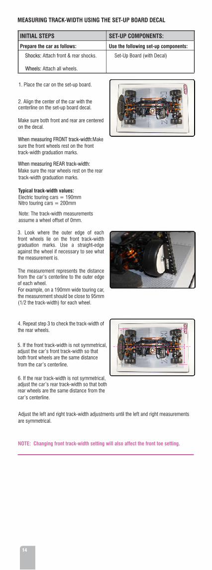
MEASURING TRACK-WIDTH USING THE SET-UP BOARD DECAL
:r
<0c
When measuring FRONT track-width: Make sure the front wheels rest on the front track-width graduation marks.
When measuring REAR track-width:Make sure the rear wheels rest on the rear track-width graduation marks.
on the decal.Make sure both front and rear are centered
centerline on the set-up board decal. 2. Align the center of the car with the
1. Place the car on the set-up board.
SE-c
(1/2 the track-width) for each wheel.the measurement should be close to 95mm For example, on a 190mm wide touring car, of each wheel. from the car’s centerline to the outer edge The measurement represents the distance
the measurement is.against the wheel if necessary to see what graduation marks. Use a straight-edge front wheels lie on the front track-width 3. Look where the outer edge of each
Typical track-width values:Electric touring cars = 190mmNitro touring cars = 200mm
Note: The track-width measurements assume a wheel offset of 0mm.
Adjust the left and right track-width adjustments until the left and right measurements are symmetrical.
NOTE: Changing front track-width setting will also affect the front toe setting.
4. Repeat step 3 to check the track-width of the rear wheels.
5. If the front track-width is not symmetrical, adjust the car’s front track-width so that both front wheels are the same distance from the car’s centerline.
6. If the rear track-width is not symmetrical, adjust the car’s rear track-width so that both rear wheels are the same distance from the car’s centerline.
ti
15
<3t*>c
_<a-w
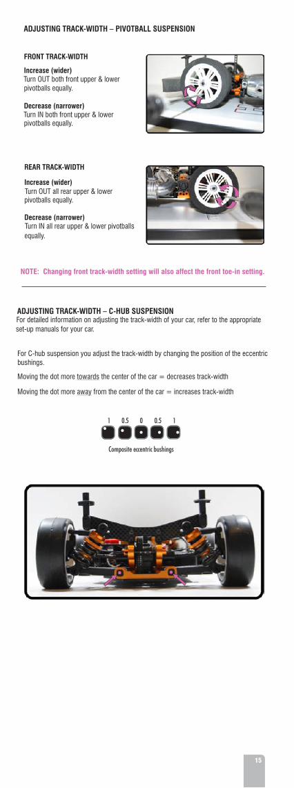
For C-hub suspension you adjust the track-width by changing the position of the eccentric bushings.
Moving the dot more towards the center of the car = decreases track-width
Moving the dot more away from the center of the car = increases track-width
ADJUSTING TRACK-WIDTH – C-HUB SUSPENSION
Turn IN all rear upper & lower pivotballs equally.
Decrease (narrower)
pivotballs equally.
Increase (wider)Turn OUT all rear upper & lower
REAR TRACK-WIDTH
NOTE: Changing front track-width setting will also affect the front toe-in setting.
pivotballs equally.
Decrease (narrower)Turn IN both front upper & lower
pivotballs equally.
Increase (wider)Turn OUT both front upper & lower
FRONT TRACK-WIDTH
ADJUSTING TRACK-WIDTH – PIVOTBALL SUSPENSION
set-up manuals for your car.For detailed information on adjusting the track-width of your car, refer to the appropriate
00.5 0.51 1
Composite eccentric bushings
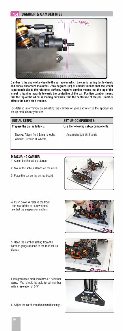
1.4 CAMBER & CAMBER RISE
Camber is the angle of a wheel to the surface on which the car is resting (with wheels and shock absorbers mounted). Zero degrees (0°) of camber means that the wheel is perpendicular to the reference surface. Negative camber means that the top of the wheel is leaning inwards towards the centerline of the car. Positive camber means that the top of the wheel is leaning outwards from the centerline of the car. Camber affects the car’s side traction.
For detailed information on adjusting the camber of your car, refer to the appropriate set-up manuals for your car.
INITIAL STEPS
Prepare the car as follows:
• Shocks: Attach front & rear shocks. • Wheels: Remove all wheels.
SET-UP COMPONENTS:
Use the following set-up components:
• Assembled Set-Up Stands
MEASURING CAMBER1. Assemble the set-up stands.
2. Mount the set-up stands on the axles.
3. Place the car on the set-up board.
5. Read the camber setting from the camber gauge of each of the four set-up stands.
4. Push down & release the front and rear of the car a few times so that the suspension settles.
Each graduated mark indicates a 1° camber value. You should be able to set camber with a resolution of 0.5°
6. Adjust the camber to the desired settings.
.
M
III tX
\
r ;'m \| >
A «J_i x.
il«V
m&£TIwfs Mira
1ÿ—mw.
/I
w
- + camber-ÿ >*—
*
16

ADJUSTING CAMBER – PIVOTBALL SUSPENSION
FRONT CAMBERIncrease (more –ve)Turn IN the front upper pivotball.
Decrease (less –ve)Turn OUT the front upper pivotball.
REAR CAMBER – REAR (LOWER) PIVOTBALLS, FIXED UPPER PIVOT
Increase (more –ve)Turn OUT both rear lower pivotballs equally.
Decrease (less –ve)Turn IN both rear lower pivotballs equally.
REAR CAMBER – REAR (LOWER) PIVOTBALLS, ADJUSTABLE UPPER CAMBER LINK
Increase (more –ve)SHORTEN the rear upper camber link.
Decrease (less –ve)LENGTHEN the rear upper camber link.
ADJUSTING CAMBER – C-HUB SUSPENSION
FRONT CAMBERIncrease (more –ve)SHORTEN the front upper camber link.
Decrease (less –ve)LENGTHEN the front upper camber link.
REAR CAMBER Increase (more –ve)SHORTEN the rear upper camber link.
Decrease (less –ve)LENGTHEN the rear upper camber link.
tf XVI - -j- cr KW "
'V *~'v ‘
*1 * ‘©fc«.y
* rr.y/- 1
/ V,
»!
*>. «L>
k
\
7«|i,'A
r/ vm *
H.Kil*
'V
17
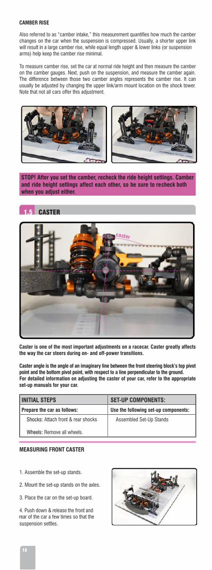
CAMBER RISE
Also referred to as “camber intake,” this measurement quantifies how much the camber changes on the car when the suspension is compressed. Usually, a shorter upper link will result in a large camber rise, while equal length upper & lower links (or suspension arms) help keep the camber rise minimal.
To measure camber rise, set the car at normal ride height and then measure the camber on the camber gauges. Next, push on the suspension, and measure the camber again. The difference between those two camber angles represents the camber rise. It can usually be adjusted by changing the upper link/arm mount location on the shock tower. Note that not all cars offer this adjustment.
STOP! After you set the camber, recheck the ride height settings. Camber and ride height settings affect each other, so be sure to recheck both when you adjust either.
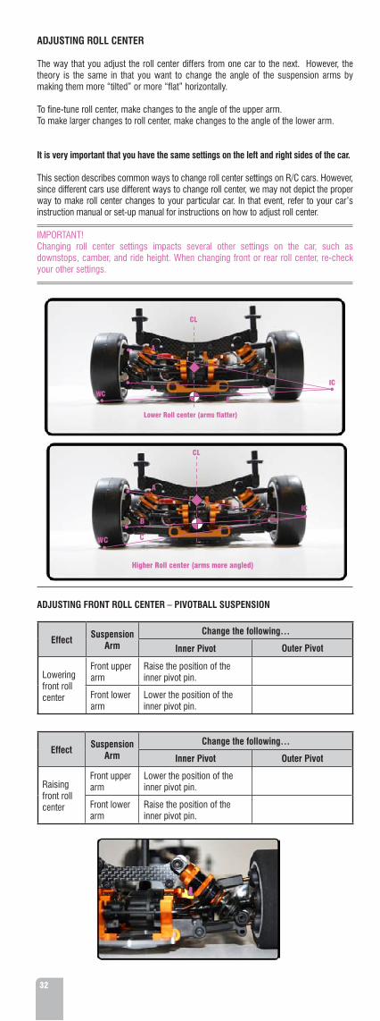
1.5 CASTER
caster
Caster is one of the most important adjustments on a racecar. Caster greatly affects the way the car steers during on- and off-power transitions.
Caster angle is the angle of an imaginary line between the front steering block’s top pivot point and the bottom pivot point, with respect to a line perpendicular to the ground. For detailed information on adjusting the caster of your car, refer to the appropriate set-up manuals for your car.
INITIAL STEPS
Prepare the car as follows:
• Shocks: Attach front & rear shocks
• Wheels: Remove all wheels.
SET-UP COMPONENTS:
Use the following set-up components:
• Assembled Set-Up Stands
MEASURING FRONT CASTER
1. Assemble the set-up stands.
2. Mount the set-up stands on the axles.
3. Place the car on the set-up board.
4. Push down & release the front and rear of the car a few times so that the suspension settles.
/
$ I
I
Ia
*!fV
IS» v18

5. Read the caster angle from the side of the front set-up stands.
Read the caster angle on the side plates between the imaginary line that goes from the top pivot point to the bottom pivot point.
Each graduated mark indicates a 2° camber value. You should be able to set camber with a resolution of 1°.
6. Adjust caster to the desired settings.
ADJUSTING FRONT CASTER – PIVOTBALL SUSPENSION
Increase (more laid back)Use MORE caster spacers in front of the front upper arm.
Decrease (more upright)Use LESS caster spacers in front of the front upper arm.
NOTE:We recommend using the #107610 HUDY EXHAUST SPRING / CASTER CLIP REMOVER.
ADJUSTING FRONT CASTER – C-HUB SUSPENSIONTo change the front caster on a car with C-hub suspension, you must change the front C-hubs to others that have a different caster value.
1.6 TOE
toe
int o
eou
t
0
toe
int o
eou
t
0
Toe is the angle of the wheels when looked at from above the car. When the wheels are parallel with the centerline of the car, toe is 0° (neutral). When the wheels are closed towards the front, this is called toe-in (positive value). When the wheels are open towards the front, this is called toe-out (negative value).
The front wheels can have either toe-in or toe-out. The rear wheels should always have toe-in; they should never have toe-out.
Rear toe-in is a primary adjustment, and will dictate the symmetry of the handling of the car. It is critical that you adjust rear toe-in perfectly symmetrical from left to right.
For detailed information on adjusting the toe of your car, refer to the appropriate set-up manuals for your car.
NOTE: Changing front track-width setting will change the front toe setting.
ny
l i
r /V
F
Il
:«
!* i! :w
I atHUE WHT
.J ?
rPT
*•
i't; WiI
A
1pMk * •
•
I
r
V V£i)''Tn * * >4
«4 t
f<3Sr
19

MEASURING TOE 1. Assemble the set-up stands.
2. Mount the set-up stands on the axles.
3. Place the car on the set-up board.
4. Turn on the transmitter.
5. Turn on the receiver. The steering should respond to the transmitter.
6. To adjust rear toe, set the toe gauge atop the rear set-up stands.
The pins at the top of the stands fit in the machined slots in the toe gauge.
7. To read the toe value of the left rear wheel, push the toe gauge to the right until the pin on the top edge of the left set-up stand hits the edge of the slot in the toe gauge.
Now read the toe value on the toe gauge. The black line on the top edge of the stand points to a toe value engraved in the toe gauge. Each graduated mark indicates a 1° toe value. You should be able to set toe with a resolution of 0.5°
To read the toe value of the right rear wheel, push the toe gauge to the left until the pin on the top edge of the right set-up stand hits the edge of the slot in the toe gauge. Read the measurement.
8. Adjust the rear toe to the desired settings.
7. To adjust front toe, set the toe gauge atop the front set-up stands and then repeat the procedure.
We recommend you adjust front toe after the rear toe and steering trim has been set.
ADJUSTING TOE – PIVOTBALL SUSPENSION
FRONT TOE
Increase (more front toe-in)LENGTHEN both front steering rods equally.
Decrease (less front toe-in)SHORTEN both front steering rods equally.
V
*
r
t
-
zr»v
j
»
j|>
V
>/
*L
Use the following set-up components:
• Assembled Set-Up Stands • Toe Gauge
e
Prepare the car as follows:
• Shocks: Attach front & rear shocks. • Wheels: Remove all wheels. • Motor: Remove the pinion gear. • Electronics: Connect the radio
electronics so the steering is activ when you turn on the car.
When using the acrylic toe gauge, the toe gauge does not fit over the pins on the set-up stands so that the toe gauge is in one position. The toe gauge is designed to slide over the pins from one side to the other, depending on which wheel you are measuring (left or right). Follow the instructions carefully.
-UP COMPONENTS:SETINITIAL STEPS
I
20

REAR TOE Increase (more rear toe-in)Turn IN the forward lower pivotball and turn OUT the rearward lower pivotball equally.
Decrease (less rear toe-in)Turn OUT the forward lower pivotball and turn IN the rearward lower pivotball equally.
ADJUSTING TOE – C-HUB SUSPENSION FRONT TOE Increase (more front toe-in)LENGTHEN both front steering rods equally.
Decrease (less front toe-in)SHORTEN both front steering rods equally.
REAR TOERefer to your car‘s instruction manual for more information about changing rear toe in.
Different cars use different methods to adjust rear toe-in, including spacers
(For example, the XRAY T4 chassis allows rear toe adjustment using eccentric bushings.).Refer to your car’s instruction manual formore information.
s tee
ring
stee
ring
Although most cars‘ front suspension geometry is designed such that the turning radius of the car is the same from left to right, sometimes this isn‘t the case. You can use the toe gauge plate to make sure that the steering turns as sharply to the left as it does to the right.
If it is not the case and if your radio has EPA (End Point Adjustments), adjust the EPA on your transmitter in order to achieve steering throw symmetry. The wheels should turn equally in both directions for balanced handling.
For detailed information on adjusting end point adjustment, refer to the instruction manual for your transmitter.
n!
Mil/t4
ik-
r_
r
* x4 L*•
; <: v
ft
\%
\ft
W
r'
i• .is
>
toe-in blocks.between the pin holders and bulkheads, or
rl
1.7 STEERING THROW SYMMETRY
t
5i C
i I0
fa
* ; i
ft
!.4
ft
I
21

INITIAL STEPS
Prepare the car as follows:
• Shocks: Attach front & rear shocks. • Wheels: Remove all wheels. • Motor: Remove the pinion gear. • Electronics: Connect the radio electronics so the steering is active when you turn on the car.
SET-UP COMPONENTS:
Use the following set-up components:
• Assembled Set-Up Stands • Toe Gauge
MEASURING & ADJUSTING STEERING THROW SYMMETRY
1. Assemble the set-up stands.
4. Turn on the transmitter.
5. Turn on the receiver. The steering shloud respond to the transmitter.
6. Set the toe gauge atop the front set-up stands.
The pins at the top of the front stands fit in the machined slots in the toe gauge.
7. Push the toe gauge to the right until the pin on the top edge of the left set-up stand hits the edge of the slot in the toe gauge.
Then slide the toe gauge to the left until it stops against the pin on the right front stand.
8. Adjust the transmitter steering trim until you get the same toe value on both front wheels.
9. Turn the steering to the left, and push the toe gauge against the pin on the right front stand.
Note the amount that the wheel turns to the left (in degrees) on the toe gauge.
10. Turn the steering to the right, and push the toe gauge against the pin on the left front stand.
Note the amount that the wheel turns to the right (in degrees) on the toe gauge.
11. Compare the amounts that the steering turns left and right. They should be the same.
If they are different, adjust the left or right EPA (end point adjustment) settings on your transmitter until the left and right steering amounts are the same.
12. Turn off your receiver, then turn off your transmitter.
(
2. Mount the set-up stands on the axles.V,
3. Place the car on the set-up board.s'*>v Ar
'sc
1
J /
!j
u
'
V
j|>
»
22

1.8 TWEAK
Correct tweak is one of the most important things that infl uences the overall performance of the car; a badly-tweaked car has a very negative impart on a car’s handling. As such, it is very important to check and correct tweak regularly; pro racers check tweak a number of times after each run.
The new HUDY Quick-Tweak Station allows you to quickly and easily check and correct tweak on your race car to help ensure proper, consistent handling.
Other “bubble-type” tweak stations are not as effective at measuring tweak as the HUDY Quick-Tweak Station; they are difficult & ineffective as they must work on an ultra-flat surface, and if it is not then the readings will not be accurate. The HUDY Quick-Tweak Station uses the tension of the suspension to determine the tweak,so you can use the tweak station under any conditions or on any surface. Also, front & rear suspensions do not have to be aligned.
The HUDY Quick-Tweak Station level indicates the amount of tweak of the end of the car resting on the set-up board (not the end of the car on the tweak station). For example, by placing the REAR stands on the tweak station and the front stands on the set-up board, the tweak station indicates the amount of tweak at the FRONT of the car.
For detailed information on adjusting the tweak of your car, refer to the appropriate set-up manuals for your car.
SET-UP COMPONENTS:
Use the following set-up components: • Alu Wheels
INITIAL STEPS
Prepare the car as follows:
• Shocks: Attach front & rear shocks. • Wheels: Attach the alu wheels. • Tweak Station
MEASURING TWEAK
Before measuring tweak, it is very important that the car has symmetrical track-width at both front & rear ends. For more information, see "Track-Width" section.
1. Assemble the HUDY Quick-Tweak Station.
2. Place the tweak station on the set-up board.
3. Mount the alu wheels on the axles.
Adjust
the
position
of
the
car to ensure each end of the car is centered
on
its
base plate.
The outer edge of each wheel (at one end of the car) should be beside equivalent marks on each side of the base plate.
4. Set the FRONT wheels on the PIVOTING base plate and the REAR wheels on the FIXED base plate (You do this to check for tweak REAR of the car).
23

COMBATING TWEAKIf your car is tweaked, there are several things you can check or adjust. Check these areas in the following order:•
Chassis flatness
•
Downstop settings
•
Shock length and damping
•
Binding parts
•
Shock spring preload
•
Anti-roll bars
Chassis Flatness
A twisted chassis will certainly cause a car to become tweaked. Since the chassis is the central attachment point for all suspension components, a twisted chassis will render all other suspension settings as unbalanced. To check for a twisted chassis, remove the wheels, disconnect the springs, and remove the battery straps. Place the chassis on a perfectly flat surface (such as the HUDY Set-Up Board) and see if the chassis rocks from side to side. Even a small amount of twisting will result in a tweaked car.
To remedy a twisted chassis, you can try releasing the screws the hold the top deck, pressing the chassis flat on the set-up board, and then retighten the screws (if you use the graphite center brace remember to also loosen the screws and retighten them) If this does not solve the problem, you may have to replace the chassis.
Downstop SettingsCheck downstop settings to make sure they are equal on the left and right sides of the car.For more information on downstops, see “Downstops” on page 10.
M
s</
• If the bubble in the spirit level is centered, there is no tweak at the OTHER end of the car.
• If the bubble in the spirit level is offset to one side, the OTHER end of
the car is tweaked.
7.
Adjust the
REAR
suspension until
the bubble is centered.
Turn the car around.
8.
Place
the
REAR wheels
on
the PIVOTING base plate,
and
place
the
FRONT wheels on the FIXED base plate(You do
this
to
check
for
tweak
at
the
FRONT of the car).
Repeat the procedures to check and adjust tweak at the front of the car.
24
suspension arms and pins, pivotballs, ball cups, etc..Make sure that all suspension components move freely without binding. This includes
Binding Parts
shock rod. Damping adjustment varies depending on the type of shock absorber.the car. You typically adjust shock length by tightening or loosening the lower pivot on the Check shock lengths and damping to make sure they are equal on the left and right sides of
Shock Length and Damping

ADJUSTING TWEAK USING SPRING PRELOADAdjusting tweak using spring preload should be done only after all other items have been checked and corrected. Incorrectly adjusted springs can result in one side of the car being firmer or higher than the other, causing handling differences when turning left or right. After adjusting spring preload to remove tweak, if the preload on the left and right sides of the car are different by more than 1~1.5mm, then you should start over again and check for other areas that may result in tweak.
This section describes how to interpret the meaning of the tweak station readings, and the adjustments to make to spring preload to adjust tweak. Make sure that both anti-roll bars are DETACHED.
Note that your car may use threaded spring preload collars or preload spacers.To adjust spring preload do the following.
Preload setting Threaded preload collar Preload spacers
Increase TIGHTEN collar so it moves Use THICKER spacers above DOWN the shock body. spring.
Decrease LOOSEN collar so it moves Use THINNER spaces above UP the shock body. spring.
ADJUSTING TWEAK (SPRING PRELOAD)
w
25
Excess load on front right
REAR TWEAK
Adjust REAR preload equally but opposite.
FRONT wheels: On PIVOTING base plate REAR wheels: On FIXED base plate
- DECREASE - preload
+ INCREASE + preload
Excess load on front left
FRONT wheels: On PIVOTING base plate REAR wheels: On FIXED base plate
+ INCREASE + preload
- DECREASE - preload

FRONT TWEAK
Adjust FRONT preload equally but opposite.
26
Excess loadon rear left
preload- DECREASE -
preload+ INCREASE +
Excess loadon rear right
FRONT wheels: On FIXED base plate REAR wheels: On PIVOTING base plate
- DECREASE - preload
+ INCREASE + preload
FRONT wheels: On FIXED base plate REAR wheels: On PIVOTING base plate

27
MAINTENANCE
The HUDY All-In-One Set-Up Solution does not require any specific maintenance. However, we recommend that you clean the components occasionally. Use a soft cloth to gently wipe any dirt off the components. Clean and lightly oil the ball-bearings occasionally.
DO NOT USE ANY ALCOHOL, ACETONE, OR ANY OTHER SPIRIT-BASED CHEMICAL on the components as it will damage them.
Do not allow any debris or contaminants to enter the ball-bearings, as this may cause premature wear or degradation.
When not in use, disassemble the components and store in the protective carrying case.
SUMMARY
We are confident that using the HUDY All-In-One Set-Up Solution to fine tune your car’s setup will help your car perform better, and turn faster and more consistent lap times at the racetrack.
Here are some basic rules to get the most from your car:
• Regularly check for some obvious set-up problems on your car, asymmetry, positive camber or similar issues. Modern adjustable suspensions can change considerably after taking a hard hit.
• Only change one thing at a time, in order to get a better understanding of what consequence each change has on the handling of your car.
• A car that “feels” faster is not necessarily turning faster lap times. The stopwatch is the only judge.
• Remember to document all the changes you make, and the effects they have on your car and lap times.
• Do not hesitate to ask for some set-up tips from the local fast drivers. Although it is better to refine your set-up knowledge by performing and understanding your own adjustments that fit your own driving style, set-up tips borrowed from other fast drivers usually are a good place to start.
Remember to enjoy your hobby, and to recommend HUDY products to your racing partners!
Best of luck at the racetrack!We hope you will be satisfied with the performance and quality of the HUDY All-In-One Set-Up Solution. If you have any questions or advice about how to further improve this product, please do not hesitate to contact us.

28
2.0 SET-UP THEORY
The Set-Up Theory section describes the effects of changing settings on your R/C car. We refer to handling effects of the car in the corner, and we distinguish three corner sections and three throttle/brake positions as follows:
• corner entry • braking • mid-corner • off-throttle • corner exit • on-throttle
Car setup is a complex matter, as all adjustments interact. Fine-tuning the setup will make the car faster and often easier to drive near its performance limit. This means that all the effort you put into your car in preparing it and optimizing the setup will pay off in better results and more satisfaction.
Chassis stiffness (especially torsional) is an important factor when setting up your car. A stiff chassis helps to eliminate chassis flexing and twisting, which would otherwise introduce another factor that is not easy to measure or adjust. However, chassis stiffness is also a setup tool. By changing chassis stiffness by changing the main chassis plate, top deck, chassis stiffeners, or other components, you can make a “softer” or “stiffer” car that may be more or less suited for racing.
If you choose to adjust your car set-up to better suit different track conditions, make small adjustments, one at a time, and see if you find any improvement in handling with each adjustment. We advise you to keep track of your set-up changes, and record which set-ups work best at different racetracks under various conditions. Remember that for the car to work and respond to set-up changes properly, it must be in good mechanical shape. Check the well functioning of critical areas such as the free movement of the suspension, smoothness of shock absorbers, and lubrication and wear of transmission parts after each run, and especially after a collision.
After rebuilding the chassis, or in case you become lost with your set-up, always return to the last set-up you have recorded, or use one of the set-ups posted for you car.
BASIC TERMINOLOGY
The terms “understeer” and “oversteer” appear throughout this manual. These terms describe a particular handling characteristic of the car.
UndersteerAlso known as “push.”A car understeers when the front wheels do not grip enough and the rear tires grip too much. This results in the front wheels sliding too much rather than turning. A car that understeers is easier to drive, but it is slower than a car that oversteers slightly.
OversteerAlso known as “loose.”A car oversteers when the front wheels grip too much and the rear tires do not grip enough. This results in a rear end that slides. Excessive oversteer causes the rear tires to “break loose” allowing the car to spin out.
WEIGHT TRANSFER
Weight transfer is the key to car handling. Consider that a car has a certain amount of “weight” on various parts of the car, and on each wheel. By transferring weight to one end of the car (front or rear), to one side (left or right), those tires will be forced onto the racing surface more, and will have more grip or traction.Weight transfer is affected by the car’s set-up and by the way that you drive.
Before you start adjusting your car set-up to maximize the car’s performance and ease of handling, you should ensure the following:• Car is in good mechanical shape with no broken, binding, or loose parts.• Car has proper weight balance front/rear and left/right.
Weight BalanceYou should always try to adjust the weight on your car so it is equal front/rear and equal left/right. This will help to ensure proper, consistent handling. You can use balancing tools to check the weight distribution of your car, and to ensure that your ready-to-race car does not list to one side or one end.

29
Examples of balancing chassis weights (front, rear, center)
A simple balancing tool can be a set of stands with points on them. You would then place the chassis on the points of the stands so that the stand are along the car’s centerline at the front and rear. If the car lists to one side (for example, to the left), add weight to the other side (say, to the right) until the car stays level when left untouched. You can do this also to check front/rear balance by putting the chassis on the balancing stands on the left and right sides half way along the length of the chassis.
NOTE: We recommend using the #107880 HUDY CHASSIS BALANCING TOOL
Center-of-GravityThe center-of-gravity (CG) of the car is the point on the car (in 3 dimensional space) around which the car moves, and the point at which all force is applied while the car is in motion.
• When the car goes around a corner, centrifugal force pushes the car to the outside of the turn, and that force pushes on the car’s CG causing the car to tilt or roll to the outside. This transfers weight to the outside wheels of the car.
• When the car accelerates, the force pushes backward on the car’s CG, causing the car to tilt backward. This transfers weight from the front wheels to the rear wheels.
• When the car brakes, the force pushes forward on the car’s CG, causing the car to tilt forward. This transfers weight from the rear wheels to the front wheels.
Center-of-gravity is affected by the physical weight of the car, and the placement of all components on the car. If the car is not equally balanced front/rear and left/right, the car’s CG will not be centered. This will cause the car to handle differently when it turns one direction as opposed to the other direction.
It is always best to make the car’s CG as low as possible to minimize the negative effects of weight transfer. Do this by placing all components down as low as possible on the car’s chassis, and reduce the weight that is up high.
Weight Transfer and Car Set-UpEvery aspect of car set-up affects the way that weight transfers on the car. There is no one magical set-up change that will solve all of your car’s handling problems. Car set-up is a complex interaction of the various components that make up the car, and all of these aspects of set-up will affect one another. Car set-up is always a matter of compromise.
cD1J«I
ne%
V
V/
«r:1 l
t
»- 4q11p *
a<3
(•
«3 4
* »
M ffc

30
2.1 ROLL CENTER
A “roll center” is a theoretical point around which the chassis rolls, and is determined by the design of the suspension. Front and rear suspensions normally have different roll centers. The “roll axis” is the imaginary line between the front and rear roll centers.
The amount that a chassis rolls in a corner depends on the position of the roll axis relative to the car’s center-of-gravity (CG). The closer the roll axis is to the center of gravity, the less the chassis will roll in a corner. A lower roll center will generally produce more grip due to the chassis rolling, and the outer wheel “digging in” more.
Roll-centers have an immediate effect on a car’s handling, whereas anti-roll bars, shocks and springs require the car to roll before they produce an effect.
ROLL CENTER BASICSHere are some basic facts about roll center (RC) and center-of-gravity (CG).
• Roll center (RC) is the point around which the car rolls.• Each end of the car (front and rear) has its own roll center.• Center-of-gravity (CG) is where all cornering force is directed.• RC and CG are (ideally) in the middle (left-right middle) of the car.• RC is vertically below the CG in cars.• More chassis roll equals more grip.
CG Center-of-gravity RC Roll center
DETERMINING ROLL CENTER LOCATIONRoll center is determined by the car’s suspension geometry. Each end of the car has its own roll center, determined by the suspension geometry at that end of the car.
The following diagram shows how you can find a car’s roll center at one end of the car or the other.
CG Center-of-gravity RC Roll center
CL
Here is a breakdown of the factors that determine roll center at one end of the car.
• Line ‘A’ is parallel to the upper suspension arm.• Line ‘B’ is parallel to the lower suspension arm.• Line ‘A’ and line ‘B’ intersect at point ‘IC’ (instant center).• Line ‘C’ goes from the wheel contact point (WC – bottom center of the wheel) to point IC.• The point at which line ‘C’ crosses the car’s centerline (CL) is the roll center.
« •1 I »i
% fri\ '
©
A
1C
C
©

31
ROLL CENTER IN ACTION
When cornering, centrifugal force is applied to the car’s CG, which tends to push the car to the outside of a corner. This causes the CG to rotate around the RC. Since the RC is below the CG, cornering force causes the car to rotate AWAY from the force. Hence, the car rolls to the OUTSIDE of the corner.
• When the RC is far away from CG (lower RC), when the car corners the CG has more leverage on the RC, so the car will roll more.
• When the RC is closer to CG (higher RC), when the car corners the CG has less leverage on the RC, so the car will roll less.
• If the RC was right on top of the CG, when the car corners the CG has no leverage on the RC, so the car would not roll at all.
• Depending on what the car is doing, you will want one end or the other to roll more or less. You change the height of the RC accordingly to make it closer or further from the CG (which for all intents is a fixed point).
Lower RC - more roll - more grip
Comering force
roll
Higher RC - less roll - less grip
Comering forceroll
EFFECTS OF FRONT ROLL CENTER ADJUSTMENTFront roll center has most effect on on-throttle steering during mid-corner and corner exit.
Front roll center Effect
Lower
Higher
• Improved forward traction • Improved steering response
• Recommended for asphalt tracks and tracks with low-medium traction.
• Decreases forward traction, • Easier to drive, less responsive • Easier to drive in chicanes and high-traction conditions. • Recommended for carpet or high traction trackss
EFFECTS OF REAR ROLL CENTER ADJUSTMENTRear roll center affects on- and off-throttle situations in all cornering stages.
Rear roll center Effect
Lower
Higher
• Improves traction• Decreases cornering speed • Increases on power push• Recommended for low traction tracks
• Improves rotation• Increases on power steering• Recommended for high traction tracks
»
• m -= - — - - f3k\
Mm. wm
\
32
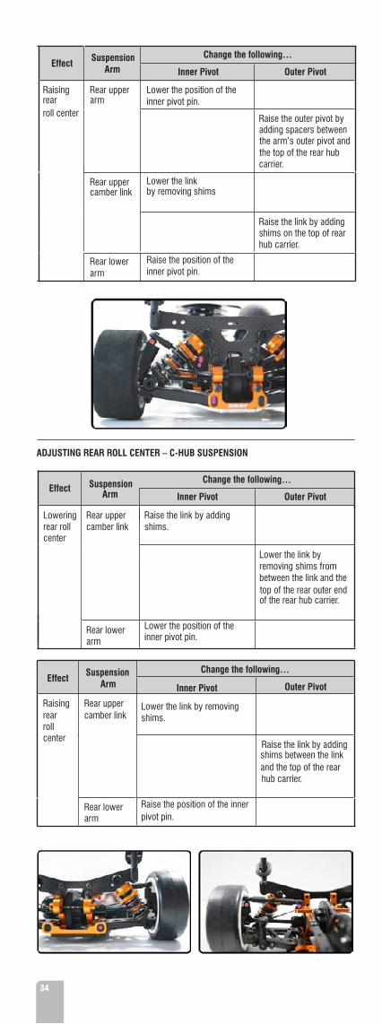
ADJUSTING ROLL CENTER
The way that you adjust the roll center differs from one car to the next. However, the theory is the same in that you want to change the angle of the suspension arms by making them more “tilted” or more “flat” horizontally.
To fine-tune roll center, make changes to the angle of the upper arm. To make larger changes to roll center, make changes to the angle of the lower arm.
It is very important that you have the same settings on the left and right sides of the car.
This section describes common ways to change roll center settings on R/C cars. However, since different cars use different ways to change roll center, we may not depict the proper way to make roll center changes to your particular car. In that event, refer to your car’s instruction manual or set-up manual for instructions on how to adjust roll center.
IMPORTANT! Changing roll center settings impacts several other settings on the car, such as downstops, camber, and ride height. When changing front or rear roll center, re-check your other settings.
CL
Lower Roll center (arms flatter)
Higher Roll center (arms more angled)
ADJUSTING FRONT ROLL CENTER – PIVOTBALL SUSPENSION
Effect Suspension Arm
Change the following…
Inner Pivot Outer Pivot
Lowering front roll center
Front upper arm
Raise the position of the inner pivot pin.
Front lower arm
Lower the position of the inner pivot pin.
Effect Suspension Arm
Change the following…
Inner Pivot Outer Pivot
Raising front roll center
Front upper arm
Lower the position of the inner pivot pin.
Front lower arm
Raise the position of the inner pivot pin.
A
1CBL
i
cI
I
ic
¥c I
CL

ADJUSTING FRONT ROLL CENTER – C-HUB SUSPENSION
Effect Suspension Arm
Lowering front roll center
Front uppercamber link
Change the following…
Inner Pivot Outer Pivot
Raise the inner mounting position on link by adding shims
Lower the outer pivot by removing shims from between the link and the top of the C-hub.
Front lower arm
.
Lower the position of the front lower arm’s inner pivot pin.
Effect Suspension Arm
Raising front roll center
Front uppercamber link
Change the following…
Inner Pivot Outer Pivot
Lower the inner mounting position on linkby removing shims
Raise the outer link by adding shims between the link and the top of the C-hub.
Front lower arm
.
Raise the position of the inner pivot pin.
ADJUSTING REAR ROLL CENTER – PIVOTBALL SUSPENSION
Effect Suspension Arm
Lowering rearroll center
Rear upper arm
Rear uppercamber link
Change the following…
Inner Pivot Outer Pivot
Raise the position of the inner pivot pin.
Lower the outer pivot by removing spacers from between the arm’s outer pivot and the top of the rear hub carrier.
Raise the link by adding shims
Lower the link by removing shims on the top rear hub carrier.
Rear lower arm
Lower the position of the inner pivot pin.
33
Effect Suspension Arm
Raising rearroll center
Rear upper arm
Rear uppercamber link
Change the following…
Inner Pivot Outer Pivot
Lower the position of the inner pivot pin.
Raise the outer pivot by adding spacers between the arm’s outer pivot and the top of the rear hub carrier.
Lower the link by removing shims
Raise the link by adding shims on the top of rear hub carrier.
Rear lower arm
Raise the position of the inner pivot pin.
ADJUSTING REAR ROLL CENTER – C-HUB SUSPENSION
Effect Suspension Arm
Change the following…
Inner Pivot Outer Pivot
Lowering rear roll center
Rear uppercamber link
Lower the link by removing shims from between the link and the top of the rear outer end of the rear hub carrier.
Rear lower arm
Raise the link by adding shims.
Lower the position of the inner pivot pin.
Effect Suspension Arm
Change the following…
Raising rearroll center
Rear upper camber link
Outer Pivot
Raise the link by adding shims between the link and the top of the rear hub carrier.
Rear lower arm
Inner Pivot
Lower the link by removing shims.
Raise the position of the inner pivot pin.
34

2.2 DOWNSTOPS
Downstops limit how far the suspension arms travel downward, which determines how far upwards the chassis rises. This affects the car’s handling, as it directly impacts the car’s weight transfer. The effect may change with the type of track and/or amount of grip available.
More suspension travel (lower downstop value) makes the car more responsive but less stable; it is also typically better on a bumpy track or on a track with slow corners. This allows the chassis to “pitch” rearward or forward more under acceleration or braking (respectively), which results in more weight transfer.
Less suspension travel (higher downstop value) makes the car more stable and is typically better on a smooth track. This prevents the chassis from “pitching” rearward or forward too much under acceleration or braking (respectively), which results in less weight transfer.
.V
I*.If*
I
*'[*]
It is very important to have the same downstop settings on the left and right sides of the car.
EFFECTS OF DOWNSTOP ADJUSTMENT
Front DownstopsHigher front downstop value
• Increases off-power steering • Increases steering response • Easier to drive in chicanes
Lower front downstop value
• Decreases steering response • Improves on-power steering • Improves cornering speed
Rear DownstopsHigher rear downstop value
• Improves stability • More on-power push
Lower rear downstop value
• Improves on-power steering • Improves cornering speed• Less stable
35
ADJUSTING DOWNSTOPSFor more information on adjusting downstops, see “Downstops” on page 10.

2.3 RIDE HEIGHT
Ride height is the height of the chassis in relation to the surface it is sitting on, with the car ready to run. Ride height affects the car’s traction since it alters the car’s center of gravity and roll center. Because of changes in suspension geometry and ground clearance, there are negative consequences to altering ride height too much.
Measure and adjust ride height with the car ready-to-run but without the body. Use the shock preload collars to raise and lower the ride height.
1
A £?&KvSA»-
reartide heighrntor ftide heighr
EFFECTS OF RIDE HEIGHT ADJUSTMENT
Ride Height and Tires Ride height is measured with the wheels on the car, and the car ready-to-run. When using rubber tires, your ride height settings should stay consistent, since rubber tires do not wear down appreciably during use, which results in a fairly constant ride height. However, if using foam tires, the car’s ride height decreases as the foam tires wear down to smaller diameters.
Tires may wear at different rates front-to-back, and left-to-right, which may eventually result in a car with uneven ride height at all four corners. You should periodically true your foam tires and readjust your settings accordingly.
• Faster reaction• More overall grip • Better on smooth tracks
• Slower reaction• Increases chassis roll• Decreases overall grip• Better on bumpy tracks • Increased steering into corner• More stability in corners• Increased on-power oversteer
Decreasing ride height(lowering the car)
Increasing ride height(raising the car)
Front
lower then rear by 0,5mm
Ride Height and Suspension Settings Suspension settings are unaffected by the wheels/tires you put on the car, only the ride height is affected. When you use a set-up system (such as the HUDY All-In-One Set-Up Solution) to set your suspension settings, the suspension settings do not change when you put different wheels on the car. With the car sitting on the ground, it may appear that certain settings are different, but this may be due to uneven tires, or tires with different diameters. However, the settings you set using a set-up system are the true suspension settings.
ADJUSTING RIDE HEIGHT
For more information on adjusting ride height, see “Ride Height” on page 12.
36
2.4 DROOP
Droop refers to the amount that the chassis travels downward after the car is dropped and the wheels touch the ground; it is also the amount that the chassis travels upward before the wheels lift from the ground. Droop is a very powerful way to adjust your car’s handling, as it adjusts the weight transfer of the car.
Droop is affected by both downstop setting and ride height adjustments. When you adjust ride height, you must also adjust downstops to maintain the same droop setting. This is particularly important when running a car with foam tires, since foam tires get smaller when run, requiring you to increase ride height periodically. Increasing ride height by itself will reduce droop value unless you compensate by changing the downstop setting.

37
EFFECTS OF DROOP ADJUSTMENT
Front DroopLess front droop • Decreases front chassis upward travel on-throttle(higher front downstop • Less rearward weight transfervalue) • Less responsive, more stable
value)
More front droop • Increases upward chassis travel on-throttle(lower front downstop • Increases rearward weight transfer
• Better on bumpy tracksRear DroopLess rear droop(higher rear downstop value)
More rear droop(lower rear downstop value)
• Better on smooth tracks.
• More responsive, less stable
•
• • • •
• • •
Decreases rear chassis upward travel off-throttle or under braking
Decreases forward weight transfer More stable under braking Better on smooth tracks Increases rear chassis upward travel off-throttle or under
braking Increases forward weight transfer More responsive, less stable Better on bumpy tracks
MAINTAINING DROOP VALUETo maintain droop values, do the following:
When you do this to RIDE HEIGHT
Also do this to DOWNSTOP Comments
Increase Decrease Increasing ride height will decrease the droop value. To compensate, decrease the downstop setting.
Decrease Increase Decreasing ride height will increase the droop value. To compensate, increase the downstop setting.
ADJUSTING DROOP You adjust droop by adjusting downstops. Droop is affected by ride height changes. For more information on downstops, see “Downstops“ on page 10. For more information on adjusting ride height, see “Ride Height” on page 12.
2.5 SHOCK ABSORBERS
Shock absorbers are a key component to setting up your R/C car. There are various aspects of shock absorbers that can be adjusted: spring choice, spring preload, shock position & orientation, and damping.

SPRINGS
XRAY SPRINGS C=2,3 - 2,6 C=2,8 C=2,6 C=2,3
C=2,5 - 2,8 C=2,9 C=2,7 C=2,5
The shock springs support the weight of the car, and different spring tensions determine how much of the car’s weight is transferred to the wheel relative to the other shocks. Spring tension also influences the speed at which a shock rebounds after compression.
Spring selection depends on whether the track is fast or slow, or has high or low grip.
Effects of Spring Selection
Stiffer • More responsive springs • Faster reaction to steering inputs • Stiff springs are suited for tight, high-traction tracks that aren’t too bumpy • When you stiffen all springs, you lose a small amount of steering,
and reduce chassis roll Softer • Slightly more traction in low-grip conditions
springs • Better for bumpy and very large & open tracks • Springs that are too soft make the car feel sluggish and slow, allowing
more chassis roll
Stiffer • Increased steering response
front • Increased in-corner steering springs • Increased on-power steering • Higher top speed • Decreased mid-corner steering • Less overal grip Softer • Decreased steering response • More overal grip
front • Smoother steering • Increased mid-corner steering, springs • Increased off-power steering • Smoother under braking Stiffer • Increased mid-corner steering
springsrear • Improved initial acceleration
• Less overall grip
38
Softer • Increased in-corner steering • Increased on-power steering rear • Decreased mid-corner steering • Smoother, more overall grip springs
Spring Tensions Spring tension determines how much the spring resists compression, which is commonly referred to as the “hardness” of the spring. Spring tension is determined by
the characteristics of the spring itself, and NOT by the amount of preload placed on the spring by spring collars or preload spacers. Characteristics such as wire material, wire
thickness, and other factors determine spring tension.
Spring tension is usually rated in a “weight” number that indicates how much weight (or force) is required to compress the spring by a specific amount. A spring with a higher “spring weight” number (such as a 30 lb. spring) will be harder to compress than a spring with a lower “spring weight” number (such as a 25 lb. spring). Manufacturers usually color-code their springs so that all springs of a specific weight have the same external colour. Note that spring colours are NOT standardized, so that a red spring from one manufacturer will not have the same spring tension as a red spring from another manufacturer.
Different manufacturers offer different spring tuning sets so that you can precisely choose the correct spring tension for your car. These springs are usually tailored for use on the manufacturer’s own shocks, which may differ from shocks or springs from other manufacturers by length, diameter, or other characteristics.
SPRING PRELOAD Spring preload should be used only to adjust ride height. For more information on ride height, see “Ride Height“ on page 12.
Adjust spring preload so that the springs are only slightly compressed when the car is fully equipped, ready-to-run. To change spring tension, change to a softer or harder spring rather than increasing or decreasing spring preload; that only changes the car’s ride height.
Your car may use threaded spring preload collars or preload spacers. To adjust spring preload do the following:
Preload setting Threaded preload collar Preload spacers
Increase TIGHTEN collar so it moves DOWN the shock body.
Use THICKER spacers above spring.
Decrease LOOSEN collar so it moves UP the shock body.
Use THINNER spaces above spring.
•
\w\}2l
39
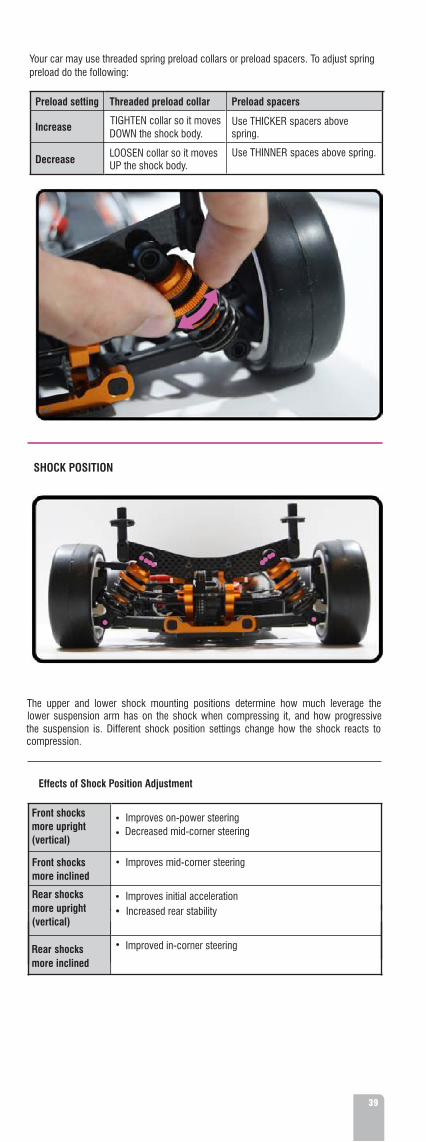
SHOCK POSITION
The upper and lower shock mounting positions determine how much leverage the lower suspension arm has on the shock when compressing it, and how progressive the suspension is. Different shock position settings change how the shock reacts to compression.
Effects of Shock Position Adjustment
Front shocksmore upright(vertical)
Improves on-power steering • Decreased mid-corner steering
Improves mid-corner steering
Improves initial acceleration
Front shocksmore inclined
Rear shocks more upright(vertical)
• Increased rear stability
Improved in-corner steering
Rear shocks more inclined
•
•
•
•

40
Thicker oil
SHOCK DAMPING Setting the right damping is always a compromise and requires a lot of “hands on” experience. Shock damping is affected by shock oil and shock piston settings.
Damping only comes into play when the suspension is moving (either vertical wheel or chassis movement or due to chassis roll), and loses its effect when the suspension has reached a stable position. When the shock is compressing or decompressing (rebounding), the shock absorber oil resists this movement. How much it resists depends on the thickness of the oil, how much the flow is restricted (affected by the number of holes in the shock piston), and the velocity of the piston. No damping means that the spring rate determines how long it takes for the spring to compress and the suspension to reach a stable position.
Shock Oil
Shock oil is usually rated in a “viscosity” number that indicates the thickness of the oil, which determines how much it resists flowing and how much it resists objects (such as shock pistons) moving through it. Shock oil with a higher “viscosity number” (such as 40W oil) will be thicker than shock oil with a lower “viscosity number” (such as 20W oil).
Shock oil thickness has the following effects on car handling:
• Slower shock action
Thinner oil
• Slower weight transfer • Car more stable at high speed, more twitchy at slow speed • Better on smooth tracks • Car less likely to become unsettled with sharp direction changes such as in chicanes
• Faster shock action• Faster weight transfer • Suspension works faster to keep the tire in contact with the surface, resulting in more traction • Better on bumpy tracks • Car more likely to become unsettled with sharp direction changes such as in chicanes
Thicker shock oil usually requires the use of heavier springs to compensate for the heavy damping action. Likewise, thinner oil usually requires lighter springs.
Damping and Shock Pistons
Shock damping manages the resistance of the shock as the piston moves up and down through the oil in the shock body.
Soft damping
Hard damping
• Produces the most grip (both front & rear) • More chassis roll• Decreases cornering speed• Allows the car to break traction more easily • Less chassis roll• Higher cornering speed
Shock pistons affect shock damping by affecting how easily the piston travels through the shock oil when the shock is compressing or decompressing (rebounding). The piston has holes through which shock oil flows as the piston travels up and down inside the shock body. The number of holes helps control how quickly the shock compresses or decompresses.
Some manufacturers offer shocks that have non-adjustable or adjustable shock pistons.
• Non-adjustable pistons usually use a 1-piece piston with a set number of holes in it. To change the shock damping, you must disassemble the shocks and replace the piston with another piston with a different number of holes.
• Adjustable pistons come in different forms, but the main idea behind them is that you can change the shock damping by altering the shock pistons without having to disassemble the shocks and changing pistons. Adjusting the shock pistons may compress an internal O-ring in the piston, or may align a different number of holes in the pistons.
Fewer piston holes/smaller piston holes
More piston holes/bigger piston holes
• Less oil can pass through the piston as the piston moves• Harder damping, reacts like using thicker shock oil• More resistance to shock movement, more damping, and
slower shock movement
• More oil can pass through the piston as the piston moves• Softer damping, reacts like using thinner shock oil• Less resistance to shock movement, less damping, and faster
shock movement

.
M
III tX
\
r ;'m \| >
- + camber-ÿ >*—
*
track width reartrack width front
z
.1A
iV
II£
ina
X
5
EFFECTS OF TRACK-WIDTH ADJUSTMENT
Front
track-width
Rear track-width
Wider
Narrower
41
For more information on adjusting camber, see “Camber & Camber Rise” on page 16.ADJUSTING CAMBER
while lower degrees of caster require more negative camber. depends on the amount of caster. Higher degrees of caster require little or no camber,
also patch contact maximum the maintain to required camber front of amount The tires wear slightly conical to the inside. Adjust front camber so that the front tires wear flat, Adjust rear camber so that the rear increased grip since the side-traction of the wheel increases.
means camber (inward) negative more Generally traction. car’s the affects Camber
ADJUSTING TRACK-WIDTH
For more information on adjusting track-width, see “Track-Width” on page 13.
2.7 CAMBER
distance from the centerline of the chassis.width is adjusted symmetrically, meaning that the left and right wheels must be the same affects the car’s handling and steering response.. It is important that front or rear track-Track-width is the distance between the outside edges of the wheels, front or rear, and it
TRACK-WIDTH 2.6
Wider
Narrower
• Decreases front traction • Decreases steering response • Easier to drive • Reduces traction rolling • Recommended for high-traction tracks
• More stable • Easier to drive • Less rotation • More on-power push • Recommended for high-traction tracks
• Less stable • Better rotation • Increases cornering speed • Recommended for low-medium traction tracks
• Increases front traction • Increases steering response • Recommended for low-medium traction tracks

42
2.8 CASTER
Caster describes the angle of the front steering block with respect to a line perpendicular to the ground. The primary purpose of having caster is to have a self-centering steering system. Caster angle affects on- and off-power steering, as it tilts the chassis more or less depending on how much caster is applied.
For the purpose of R/C cars, it is generally recommended that you use a steeper caster angle (more vertical) on slippery, inconsistent and rough surfaces, and use a shallower caster angle (more inclined) on smooth, high-grip surfaces.
EFFECTS OF CASTER ADJUSTMENT
Less caster angle(more vertical)
More caster angle(more inclined)
• Decreases straight-line stability • Increases off-power steering at corner entry • Increases suspension efficiency• Decreases on-power steering in mid-corner and corner exit
• Increases straight-line stability • Decreases off-power steering at corner entry • Increases on-power steering in mid-corner and corner exit. • More stable in bumpy track conditions
Camber vs. CasterCamber is all about contact patch – keeping as much tire on the ground as possible. Camber and caster are related in that caster can afford an amount of EFFECTIVE CAMBER change when the front wheels are turned in a corner.
Caster has the effect of progressively leaning the front tires into the direction of the corner. The more the caster angle is laid-back, the greater the effective camber change when the wheels are turned. This happens because the tops of the wheels BOTH TILT towards the inside of the corner; the wheels “dig in” more, counteracting the centrifugal forces pushing the car to the outside. Compare that to the static camber of the wheels, which is adjusted with the car sitting on a level surface and the wheels pointed straight ahead. Static camber adjustments primarily affect the outside wheels, since these are the wheels that bear the majority of the load during cornering.Hence, the amount of front camber required to maintain maximum tire contact largely depends on the amount of caster. A steeper caster angle requires more camber, while a shallower caster angle requires less camber.
Steeper Caster (More Vertical)
Increased OFF-power steering INTO a cornerWhy? Imagine that the caster angle is vertical. Now imagine that you turn the steering; the wheels turn to the side. The steeper the caster angle, the more that the wheels deflect to the side, giving you more turn-in into a corner.
Increased suspension efficiencyWhy? The inboard suspension pins are, for the sake of discussion, parallel the chassis (horizontal) which means that the suspension arms move up and down vertically. Now, imagine that the caster angle is vertical, meaning that the top and bottom of the steering “kingpin” is directly aligned with the motion of the suspension arms. And finally, acknowledge that shock absorbers are pretty much horizontally aligned (the top is no further ahead of or behind the bottom), running perpendicular to the long axis of the car. Since bumps in the racing surface cause vertical deflections of the wheel, the more
I
a
I
I
I$ retsac

43
vertically oriented the steeringblock is, the better the front suspension can soak-up bumps without binding.
Decreased ON-power steering OUT of a cornerWhy? When you increase the power coming out of a corner, the weight bias shifts from the front wheels to the rear wheels. The more vertical the caster angle, the less the effective camber change of the wheels, so that ONLY the static camber of the outside wheel is affecting how much the wheels “dig in”. Since the wheels cannot “dig in” effectively, the reduced weight on the front wheels will cause the front to lose traction more easily, causing the car to understeer.
Decreased wheel-centeringWhy? Imagine that the caster angle is vertical. Now imagine that you take hold of the forward edge of a front tire and move it from side-to-side. The wheel deflects an amount proportional to how much you move it with your hand. Vertical caster is highly unstable because there is little in the way of forces to want to keep the wheels pointing straight ahead.
Shallower Caster (More Laid-Back)
Decreased OFF-power steering INTO a cornerWhy? Imagine that the caster angle is so laid-back that it is horizontal (though this would be impossible). Now imagine that you turn the steering; the wheels would not turn to the side anymore, but rather the tops of the wheels would now tilt to the side. The shallower the caster angle, the less the wheels deflect to the side, giving you less turn-in into a corner.
Increased ON-power steering OUT of a cornerWhy? The more laid-back the caster angle, the more effective camber you get when you turn the front wheels. When you increase the power coming out of a corner, the weight bias shifts from the front of the car to the rear. Normally this would cause front to lose traction and understeer. However, since there is more effective camber at more laid-back caster angles, the “tilted” front wheels are more able to “dig” into the corner, allowing the car to resist centrifugal force and giving it a greater amount of control when exiting a corner.
Increased wheel-centering, but decreased straight-line stabilityWhy? Imagine that the front wheels of a shopping cart (which have extremely shallow caster). Push the cart forward, and the front wheels will always try to center themselves. The shallower the caster angle, the more the steering is always fighting to get back to center. However (you knew this was coming, right?), the shallower you make the caster angle, the greater the amount of force trying to center the wheels. Eventually the forces become so great that the wheels will start to shimmy, decreasing straight-line stability.
ADJUSTING CASTER
For more information on adjusting caster, see “Caster” on page 18.
2.9 TOE
Toe is the angle of the wheels when looked at from above the car. When the wheels are parallel with the centerline of the car, toe is 0° (neutral). When the wheels are open towards the front, this is called toe-out (negative value). When the wheels are closed towards the front, this is called toe-in (positive value). Toe is used to stabilize the car at the expense of traction, as it introduces friction and therefore some slip in the tires.
Front wheels should be set to neutral or toe-out. Rear wheels should always have toe-in; they should never have toe-out.
«rS3
<f
t«4>4**n £i)''TVV
r
••*pMk1
A
I Wii't;•*
T P r?J.T
WHHUE t aIw :! i
* !«
:lI
0
tuoeot
nie ot
0
tuoeot
nie ot
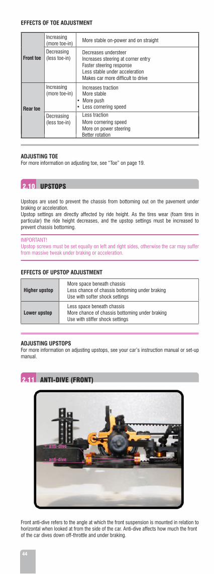
44
Front toe
EFFECTS OF TOE ADJUSTMENT
Increasing • More stable on-power and on straight (more toe-in)
Decreasing(less toe-in)
• Decreases understeer • Increases steering at corner entry • Faster steering response • Less stable under acceleration • Makes car more difficult to drive
Rear toe
Increasing (more toe-in)
•
Increases traction
•
More stable
• More push • Less cornering speed
Decreasing(less toe-in)
• Less traction • More cornering speed • More on power steering
ADJUSTING TOE For more information on adjusting toe, see “Toe” on page 19.
2.10 UPSTOPS
Upstops are used to prevent the chassis from bottoming out on the pavement under braking or acceleration.Upstop settings are directly affected by ride height. As the tires wear (foam tires in particular) the ride height decreases, and the upstop settings must be increased to prevent chassis bottoming.
IMPORTANT!Upstop screws must be set equally on left and right sides, otherwise the car may suffer from massive tweak under braking or acceleration.
EFFECTS OF UPSTOP ADJUSTMENT
Higher upstop
Lower upstop
• More space beneath chassis • Less chance of chassis bottoming under braking • Use with softer shock settings
• Less space beneath chassis• More chance of chassis bottoming under braking • Use with stiffer shock settings
ADJUSTING UPSTOPSFor more information on adjusting upstops, see your car’s instruction manual or set-up manual.
2.11 ANTI-DIVE (FRONT)
Front anti-dive refers to the angle at which the front suspension is mounted in relation to horizontal when looked at from the side of the car. Anti-dive affects how much the front of the car dives down off-throttle and under braking.
*<99999
w
+ anti-dive
- anti-dive
it
m
*
Better rotation•

45
A car with no front anti-dive will have the front suspension arms level with the chassis plane.A car with positive anti-dive will have the front suspension arms tilted “backwards” so that the front of the arm is higher than the rear of the arm.
EFFECTS OF FRONT ANTI-DIVE ADJUSTMENT
No anti-dive(front arms level)
• More weight transfer to the front of the chassis off-throttle or under braking
Positive anti-dive(front arms angled backwards)
• Chassis compresses or drops more off-throttle or under braking • Works better on bumpy track s• Decreases steering response
• Less weight transfer to the front of the chassis off-throttle or under braking • Chassis compresses or drops less off-throttle or under braking • Works better on smooth tracks • Increases steering response
ADJUSTING ANTI-DIVEFor more information on adjusting front anti-dive, see your car’s instruction manual or set-up manual.
2.12 ANTI-SQUAT (REAR)
3 anti-squat
0 anti-squat
Rear anti-squat refers to the angle at which the rear suspension is mounted in relation to horizontal when looked at from the side of the car. Anti-squat affects how much the rear of the car dives down on-throttle.
A car with no rear anti-squat will have the rear lower suspension arms level with the chassis plane.
A car with positive anti-squat will have the rear lower suspension arms tilted “backwards” so that the front of the arm is higher than the rear of the arm.
(rear arms level)
EFFECTS OF REAR ANTI-SQUAT ADJUSTMENT
• More weight transfer to the rear of the chassis on-throttle No anti-squat
Positive anti-squat(rear arms angled backwards)
• Chassis compresses or drops more on-throttle • Increases steering response • Better on a bumpy track
• Less weight transfer to the rear of the chassis on-throttle • Chassis compresses or drops less on-throttle• Decreases steering response• Increases rear traction• Better on a smooth track
ADJUSTING ANTI-SQUAT
For more information on adjusting rear anti-squat, see your car’s instruction manual or set-up manual.
J
f
m
l
ii
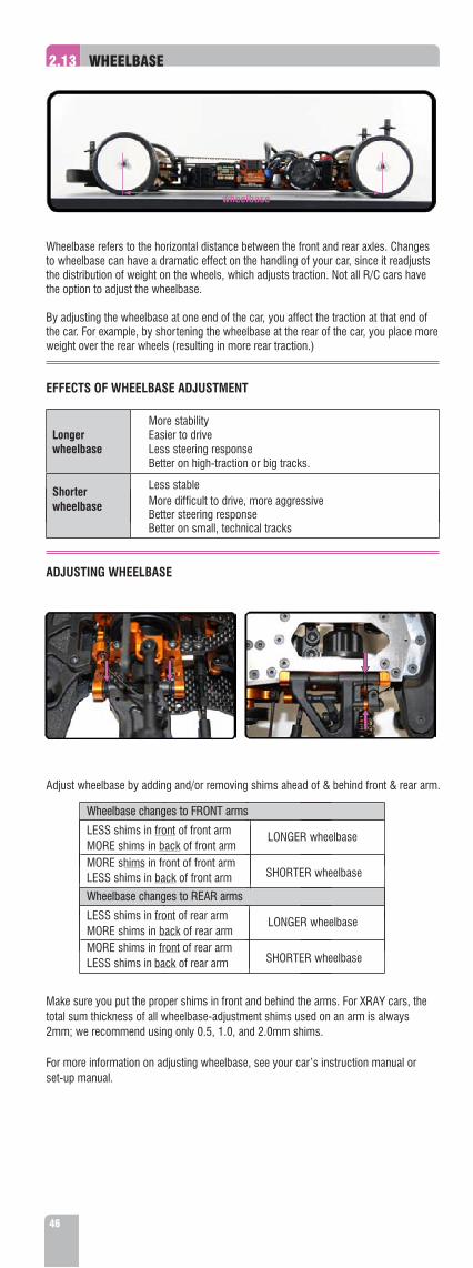
46
2.13 WHEELBASE
wheelbase
Wheelbase refers to the horizontal distance between the front and rear axles. Changes to wheelbase can have a dramatic effect on the handling of your car, since it readjusts the distribution of weight on the wheels, which adjusts traction. Not all R/C cars have the option to adjust the wheelbase.
By adjusting the wheelbase at one end of the car, you affect the traction at that end of the car. For example, by shortening the wheelbase at the rear of the car, you place more weight over the rear wheels (resulting in more rear traction.)
EFFECTS OF WHEELBASE ADJUSTMENT
Longer wheelbase • Less steering response
Shorter wheelbase
• More stability • Easier to drive
• Better on high-traction or big tracks.
• Less stable • More difficult to drive, more aggressive • Better steering response Better on small, technical tracks
ADJUSTING WHEELBASE
Adjust wheelbase by adding and/or removing shims ahead of & behind front & rear arm.
Make sure you put the proper shims in front and behind the arms. For XRAY cars, the total sum thickness of all wheelbase-adjustment shims used on an arm is always 2mm; we recommend using only 0.5, 1.0, and 2.0mm shims.
For more information on adjusting wheelbase, see your car’s instruction manual or set-up manual.
A
m fefJL: £
z-v*•
4*i s
* •>
S*l«
•
LONGER wheelbase
SHORTER wheelbase
Wheelbase changes to FRONT arms
SHORTER wheelbaseLESS shims in back of rear arm
LESS shims in front of front arm MORE shims in back of front arm MORE shims in front of front arm LESS shims in back of front arm Wheelbase changes to REAR arms
LESS shims in front of rear arm LONGER wheelbase MORE shims in back of rear arm MORE shims in front of rear arm

47
2.14 ANTI-ROLL BARS
Anti-roll
bars
are
used
to
adjust
the
car’s side
(lateral)
traction.
Anti-roll
bars
resist chassis roll and by doing so transfer wheel load
from
the
inside
wheel
to
the
outside wheel. The stiffer the anti-roll bar, the more load is transferred from the inside wheel to the outside wheel. However, as the outside wheel is not able to convert all of the extra wheel load into extra grip, the sum of the grip
of
both
wheels
is
actually
reduced. This changes the balance of the car to the other axle.
Increasing the stiffness of an anti-roll bar on one particular axle decreases the side traction of that axle and increases the side traction of the other axle.
Keep in mind that the overall traction of a car cannot be changed, but it can be balanced by distributing wheel loads. Anti-roll bars are a very useful tool to change the balance of the car.
Chassis stiffness plays a very important role in the effectiveness of anti-roll bars. A stiffer chassis makes the car more responsive to anti-roll bar changes.
Stiffer
FRONT ANTI-ROLL BAR The front anti-roll bar affects mainly off-power steering at corner entry.
Effects of Front Anti-Roll Bar Adjustment
• Less chassis roll
• Reduces off-power steering at corner entry (increases understeer)
Softer • • Decreases rear traction
• Decreases front traction • Increases rear traction
• Quicker steering response
• More chassis roll Increases front traction
• Increases off-power steering (may cause oversteer)
REAR ANTI-ROLL BAR The rear anti-roll bar affects mainly on-power steering and stability in mid-corner and at corner exit.
Effects of Rear Anti-Roll Bar Adjustment
Stiffer
• Less chassis roll
• Increases on-power steering (may cause oversteer) • Quicker steering response in high speed chicanes
More chassis roll
• Decreases rear traction • Increases front traction
• • Increases rear traction Softer • Decreases front traction
• Decreases on-power steering (increases understeer)
ADJUSTING ANTI-ROLL BARSFor more information on adjusting anti-roll bars, see your car’s instruction manual or set-up manual.

48
2.15 FRONT AND REAR AXLES Modern R/C cars can use several different types of front and rear axles. The choice of front and rear axles depends on track conditions and driving style. At the moment the most commonly-used axles are solid axle and gear differential.
Front axles •
gear differential •
solid axle
Rear axles
You may use any combination of front and rear axles, but some work better together than others.
gear differential •
<0
shock position, or caster).be made to the suspension (for example, roll center, front spring rate and/or dampening, more sensitive to tire diameter differences. To compensate for these effects, changes can The drawbacks of a front solid axle are less off-power steering, and the car becomes
Overall, using the front solid axle makes the car quite easy to drive.than if you were using a front one-way axle (which would give rear wheel braking only). steering, and allows the car to brake using all four wheels. This lets you brake much later
A front solid axle is typically used on large open outdoor tracks, or tracks that feature braking areas or slippery (low-traction) conditions. A front solid axle increases on-power
FRONT SOLID AXLE
used with it.used on, and the other type of axle being dependent on which end of the car it is at all times. The effect of a solid axle is together so they rotate at the same speed A solid axle ties both left and right wheels
SOLID AXLES
<0need for frequent oil changes, and no
no …maintenance for a very long timecorrectly built, there is no need for maintenance-free. When the diff is advantage of the gear diff is that it is carpet and asphalt tracks. Another key types of tracks, and is ideal for both steering which is needed on nearly all Gear differential increases on-power
GEAR DIFFERENTIAL
leakage due to the superior sealing system.
Thinner oil
• Less on-power steering • Better stability under braking • Less cornering speed
Thicker oil
• More on-power steering • Less stability on break
• More cornering speed • Higher steering response • More forward traction
EFFECTS OF GEAR DIFFERENTIAL ADJUSTMENT Front Differential Rear Differential
• Less steering response • Less traction • Less forward traction • More stability
• Less stability• More on-power steering
• Less on-power steering • More off-power rotation & steering • Higher traction
• Less off-power rotation & steering

3.0 SET-UP QUICK REFERENCE
The quick reference table is a simple-to-use set-up guide. With the car’s handling characteristics listed on the left of the table, suggestions for solutions are presented in order of importance and also shows whether the adjustment should be a positive or negative change.
HOW TO USE THE QUICK REFERENCE TABLE
A. Identify the Problem
After driving your car and getting a feel for how it’s handling bring it in and decide where you feel the car could improve.
B. Using the Table
The table is separated into five main areas that represent the car’s main handling characteristics: • Understeer• Oversteer• Traction roll• Straight line stability• Steering response
Understeer, oversteer, and traction roll are further separated to identify exactly where the problem occurs (corner entry, mid-corner, corner exit) and throttle position (off- or on-throttle).
Isolate the Problem
1. In the leftmost column, select the handling characteristic that best describes your car’s handling problem.
2. Identify the part of the corner that the handling characteristic occurs in.Example: Oversteer, corner entry.3. Further identify the throttle setting when the handling characteristic occurs.Example, Oversteer, corner entry, off-throttle.
You can now identify the row on the table that will contain information that can assist you.
Identify the Solution
4. On the table row that isolates the problem, there are squares with numbers in them. These numbers are recommendations for the order in which to change things. Number 1 items should be done first, number 2 items should be done second, and so on.
5. Look at the location of the square; it will be in the “Front” section or the “Rear” section. This indicates if the changes must be made at the front or the rear of the car. Example: Make changes first to Tires (front), and Anti-Roll Bars (front & rear).
6. Look at the colour of the box. This tells you how to make the change. Red means to make the setting harder/increase/higher/longer. Green means to make the setting softer/decrease/lower/shorter.Example: Make front tires harder. Make front anti-roll bar harder. Make rear anti-roll bar softer.
C. Test the Solution
When making setup changes, we strongly recommend that you try one adjustment at a time, and then test the new setting. If it has not had the expected result you can either try the rest of the changes or increase the amount of the change. If you feel you would like to try something different simply move on to the next level of possible adjustments. (For example, after trying all number 1 recommendations, move on to number 2 recommendations and so on).
Note that car set-up is always a compromise and changing one setting affects the handling of another part of the car. It is therefore important to only make small changes at a time and test each change.
49

QUICK REFERENCE TABLE
Hard
er /
Incr
ease
/ Hi
gher
/
Leng
then
/ Do
not
Use
So
fter /
Dec
reas
e / L
ower
/
Shor
ten
/ Use
Or
der o
f imp
orta
nce
FRON
TRE
AR
Off-Throttle
On-Throttle
Downstops
Camber
Caster
Ride Height
Toe
Roll Center
Anti-Roll bar
Tires
Shock Springs
Shock Damping
Shock Position
One-Way Front Axle
Solid Front Axle
Front Differential
Downstops
Camber
Ride Height
Dynamic rear steering
Roll Center
Anti-Roll bar
Tires
Shock Springs
Shock Damping
Shock Position
Rear Differential
Solid Rear Axle
Gurney Strip
How
to g
et ri
d of
UNDE
RSTE
ER
Corn
er E
ntry
56
45
53
11
33
45
56
36
53
21
33
34
43
32
63
58
21
34
34
55
67
55
32
11
33
44
33
Mid
Cor
ner
56
45
83
11
35
45
56
76
53
21
33
54
45
32
63
58
21
34
54
55
68
55
32
11
35
44
33
Corn
er E
xit
26
35
72
13
43
45
56
85
53
21
14
23
43
3Br
akin
g6
64
57
42
44
54
33
43
45
32
11
33
33
How
to g
et ri
d of
OVER
STEE
R
Corn
er E
ntry
56
45
53
11
33
45
56
36
53
21
33
34
43
32
63
58
21
34
34
55
67
55
32
11
33
44
33
Mid
Cor
ner
56
45
83
11
35
45
56
76
53
21
33
54
45
32
63
58
21
34
54
55
68
55
32
11
35
44
33
Corn
er E
xit
26
35
72
13
43
45
56
85
53
21
14
23
43
3Br
akin
g6
64
57
42
44
54
33
43
45
32
11
33
33
How
to g
et ri
d of
TRA C
TION
ROL
L
Corn
er E
ntry
82
12
11
23
44
45
36
13
21
13
45
22
36
82
12
11
34
54
45
56
13
21
12
34
22
3M
id C
orne
r6
82
12
11
25
54
45
56
13
21
12
55
55
3Co
rner
Exi
t6
82
12
11
34
54
45
61
32
11
23
42
23
Brak
ing
82
12
11
23
44
45
36
13
21
13
45
22
3ST
RAIG
HT L
INE
STAB
ILIT
Y To
mak
e Be
tter
75
37
47
53
84
88
88
56
77
38
48
66
2ST
EERI
NG R
ESPO
NSE
To m
ake
F ast
er6
44
51
24
21
44
23
44
34
4
1
Key Guide
11 III
50

Factors like quality, safety, appearance, comfort, and ease-of-use are fundamental design concerns which are addressed during the development and production of any piece of equipment that HUDY makes.
HUDY uses the most modern high-tech engineering technologies available; designing, processing, analyzing, and testing are accomplished with the use of high-end CAD PRO ENGINEER - 3D software system.All advertising and promotion strategies, as well as the whole corporate identity, are executed by a professional team of marketing managers, designers, and developers.
Before beginning production, each prototype is accurately analyzed, and tested in extreme overload conditions. The whole test process is focused on the item‘s features, its reliability characteristics, and the life span of each of its parts and components, which HUDY strives to maximize.
HUDY‘s manufacturing facility is the most modern in the RC industry. Hudy employs over ?90 professionals,and the manufacturing facility is large over 2000m2 and HUDY uses only the most modern, computer controlled, state-of-the-art CNC machines available, to ensure the highest quality products. The production facility consists of six CNC milling machines, four CNC cutting machines, CNC moulding machine, computer controlled injection machine, cutting automats, mills, 10 high-precise grinding machines and plenty of other high-tech equipment.
HUDY is one of the very few authentic manufacturers, and all HUDY products are fully manufactured and assembled in-house to guaranty the highest quality.
HUDY products are developed, designed and styled by Dipl. Eng. Juraj Hudy
U-<‘1
I
I,
I
J
0
‘
Vr2 'A
r i<
J
I %
\
/it? ,V
M {Li-/W—
SEUROPE
51