2048 PMU/NTU - Verilink · • AMI or HDB3 coding • User and PTT access via FDL link ... 1-4...
33
T R A N S P O R T ® Introduction 2048 PMU/NTU Reference Manual 34-00179 2nd Edition
Transcript of 2048 PMU/NTU - Verilink · • AMI or HDB3 coding • User and PTT access via FDL link ... 1-4...

T R A N S P O R T
®
Introduction
2048PMU/NTU
Reference Manual34-001792nd Edition

1
4
5
7
9
0
1
1
Table of Contents
General
Introduction ................................................................. 1-
Design Highlights ....................................................... 1-2
Specifications .............................................................. 1-
FCC/European Requirements .................................... 1-
Warranty ...................................................................... 1-
Ordering Numbers ...................................................... 1-
TxPORT Customer Service ....................................... 1-
Installation
Introduction ................................................................. 2-
Safety Summary ......................................................... 2-
Unpacking And Inspection ........................................ 2-1
Supplied Materials ...................................................... 2-
Mounting ..................................................................... 2-
Stand-alone Unit ................................................. 2-1
Chassis Assembly ............................................... 2-
Unit Configuration ..................................................... 2-2
Switch SW1 (BERT Pattern) ............................... 2-2
Switch SW2 (National Bit) ................................. 2-2
Switch S1 (Network LBO) .................................. 2-2
Switch S2 (Chassis Operation) ........................... 2-
Switch S4 (Configuration) ................................... 2-3
Switch S5 (Configuration) ................................... 2-3
Switch S6 (Bit Rate Selection) ............................. 2-4
Switch S7 (Address) ............................................ 2-4
Equipment Connection ................................................ 2-
Network Connection ................................................... 2-
Network Management ................................................ 2-
Supervisory Port ................................................... 2-
PTT Port .............................................................. 2-
User Port ............................................................. 2-
Chassis Network Management ............................. 2-
Alarm Connection ....................................................... 2-
Stand-alone Unit ................................................. 2-8
Chassis Assembly ............................................... 2-
Power Connection ...................................................... 2-
Stand-alone Unit ................................................. 2-8
Chassis Assembly ............................................... 2-
1
2
3
3
4
4
1
1
1
1
2
3
5
5
5
5
6
7
7
8
8
8
8
Operation
Introduction ................................................................. 3-1
Front Panel Descriptions ............................................. 3-1
General Status Indicators ...................................3-1
Alarm Controls & Indicators ..............................3-1
Test Controls & Indicators ................................. 3-2
Front Panel Testing ..................................................... 3-2
Test Switch ......................................................... 3-2
Test Access Jacks .............................................. 3-2
Supervisory Port ................................................. 3-2
BERT Pattern Select ............................................ 3-2
Terminal Operation
Introduction ................................................................. 4-1
System Description ..................................................... 4-1
Modem Compatibility .......................................... 4-1
Screen Components ............................................. 4-
Interface Start Up ................................................. 4-2
Daisy-Chain Menu Operation ............................. 4-2
Cursor Controls .................................................... 4-2
Field Types .......................................................... 4-3
Main Menu Screen ...................................................... 4-3
Alarms Screen ............................................................. 4-
Performance Screens ................................................... 4-
Maintenance Screen .................................................... 4-
Test Loops ........................................................... 4-8
BERT ................................................................... 4-8
Line Fault and Loop Status .................................. 4-8
Configuration Screens ................................................. 4-
Line Configuration .............................................. 4-9
Alarm Configuration ............................................ 4-10
Utilities Screen ............................................................ 4-1
General Functions ................................................ 4-1
COA Parameters .................................................. 4-1
Index
Configuration Guide

Copyright / Liability
Copyright
© 1995 TxPORT, All rights reserved. No part of this publication may be reproduced, trans-mitted, transcribed, stored in a retrieval system, or translated into any language in any formby any means without the written permission of TxPORT.
Reorder # 34-00179
2nd Edition, July 1995
TxPORT shall not be liable for errors contained herein or for incidental or consequentialdamages in connection with the furnishing, performance, or use of this material. TxPORTreserves the right to revise this publication from time to time and make changes in contentwithout obligation to notify any person of such revision changes.
Contents of this publication may be preliminary and/or may be changed at any time withoutnotice and shall not be regarded as a warranty.
Documentation Disclaimer
TxPORT makes no representation or warranties of any kind whatsoever with respect to thecontents hereof and specifically disclaims any implied warranties of merchantability or fit-ness for any particular purpose.

dti-
ionaphndU
atatherfor-
ead,ssedor-di-
tedodod.ceng
oneiderk.as-rt
anthedi-dded00plete
la-di-ed A
on-
or-ase
BV/CR/FE
LOCFAR
ACO SW
ACO
LOS/LOF
AIS
REM ALM
LOC ALM
NET
DTE
TST
LLB
PLB
TST
ERR
FRMNET
MON
TODTE
TONET
MON
FRMDTE
SUPV
2048PMU/NTU
TxPORT 2048 PMU/NTU
T R A N S P O R T
®
5
1
7
90
6
8234SW1
General
1.0 Introduction
The TxPORT International 2048 PMU/NTU (PerformancMonitoring Unit/Network Terminating Unit) is an advancenetwork device capable of operating in framed or mulframed (G.704) modes, using AMI or HDB3 line coding.
The 2048 is designed for CEPT E1 (2.048 Mb/s) connectto the PTT (the national Postal, Telephone, and Telegrauthority) by the user. The unit provides end-to-end inbaprotocol via a selectable national bit. This allows one PMto interrogate and control the remote far end PMU.
The 2048 is equipped with a dual set of performance dregisters that hold line statistics for both the PTT and user. Each register set provides detailed status and pemance history for the network and equipment interfaces.
The PTT performance data registers may be accessed, rand cleared by the PTT. User registers can only be acceby the user. Both registers contain identical core perfmance information, but the user registers also contain adtional fields relating to unit configuration and status.
Performance data (per TR54016 and G.821/X) is collecin 15-minute increments for the preceding 24-hour periand in 24-hour increments for the preceding 30-day periThe unit enables downloading of remote site performandata from the far end PMU, in all modes of operation, usithe facility data link (user selectable national bits).
The PMU provides access to the data registers through front and two rear management ports. These ports provtest, diagnostics, and control over the CEPT E1 netwoProgram upgrades may be downloaded into electrically erable memory (EPROM) in the field via the supervisory poon the front panel.
Access can also be obtained through a data link usingassigned national bit. The national bit data link uses 54016 U.S. FDL TABS protocol and message set. Adtional request/response FDL messages have also been ato enhance the PMU’s operation. The TxPORT EM80network manager uses these messages to provide comend-to-end control and performance monitoring.
The 2048 also provides features to aid in quick fault isotion. Front panel indicators display alarm and test contions. Test jacks allow bridged monitoring of the passsignal and signal insertion toward the PTT or the user.
2048 PMU/NTU
e
front panel test switch activates local/remote loops and ctrols the internal BERT generator and comparator.
The optional EM8000 Element Manager is available fapplications requiring multiple PMUs. The EM8000 provides access, control, testing, alarm reporting, and databmanagement functions.
General 1-1
V
1.1 Design Highlights
• End-to-end user control and access to extensive unit performance dataunit configurationunit status (normal, looped, alarm)
• AMI or HDB3 coding
• User and PTT access via FDL link
• Dual performance registers - User and PTT/carrier
• Jitter control of network signal (per G.823)
• Complete diagnostic capabilities, including multiple loopbacks and built- in BERT
• Front panel test jacks, alarm indicators, and test switch
1.2 Specifications
Network Interface
Line Rate: 2.048 Mb/s, ± 50 ppm, PCM-30
Multi-frame Type: CAS and/or CRC4, or none
Line Code: AMI or HDB3
Connection: 120 ¾ balanced or 75 ¾ unbalanced
Backplane: DB15, Twin-axial, and BNC options
Output Signal: 75 ¾ mark 2.37 V, space 0 ± 0.237 V(per G.703) 120 ¾ mark 3 V, space 0 ± 0.3 V
Line Build Out: 0, -7.5, -15 dB switch settings
Input Signal: 75 ¾ mark 2.37 V, space 0 ± 0.237 V(per G.703) 120 ¾ mark 3 V, space 0 ± 0.3 V
attenuated by 0 to -27 dB (ALBO)
Jitter Attenuation: per CCITT G.823
AIS: Unframed or framed all ones, or (user selectable) line loopback
Overvoltage: 1000 V minimum protection
Equipment Interface
Line Rate: 2.048 Mb/s, ± 50 ppm, PCM-30
Multi-frame Type: CAS and/or CRC4, or none
Line Code: AMI or HDB3
Output Signal: 75 ¾ mark 2.37 V, space 0 ± 0.237 V(per G.703) 120 ¾ mark 3 V, space 0 ± 0.3 V
Pulse Width: 244 ns, nominal
DTE Input Signal: 75 ¾ mark 2.37 V, space 0 ± 0.237 (per G.703) 120 ¾ mark 3 V, space 0 ± 0.3 V
attenuated by 0 to -6 dB at 1024 kHz (0 dB = 2.4 V)
Connection: 120 ¾ balanced or 75 ¾ unbalanced
Backplane: DB15, Twin-axial, and BNC options
AIS: Unframed or framed all ones, or line loopback
Overvoltage: 1000 V minimum protection
Diagnostics
Line Loopback: Signal regeneration only
Payload Loopback: Signal regenerated with new frame synchronization and CRC4
BERT: 63, 511, 2047, 215 (default), 220, 223, QRW, and ALT
BERT Activation: Front panel switch for test. User selection of BERT patterns via command. Pattern sync and bit errors reported via command.
Loopback Control: Inband loop up, 00001 for Ý 5 sec Inband loop down, 001 for Ý 5 sec User enable/disableManual loopback switchFDL loopback command
PTT and EM8000 Full ESF performance monitoring through a terminal port (6-pin RJ11),and via FDL in selected national bit
Jack Access
Toward Network: Bantam jacks (In, Out, and Monitor)
Toward DTE: Bantam jacks (In, Out, and Monitor)
Access Ports
User Net Manager: Asynchronous, RS232
Telco Net Manager: Asynchronous, RS232
Local Access: Asynchronous, RS232
Bit Rates: 1200, 2400, 9600 or 19200 b/s (all ports) (switch selectable)
Formats: 8 data bits, 1 stop bit, no parity
1-2 General 2048 PMU/NTU
fre-ncece ain
er-
m-
ndhe atr
sivet,ustednt.
n.ent
asvice
e-
inte-
Protocol: TxPORT COMVIEW (proprietary) ASCII VT100
Connection: All ports, 4-pin modular
Alarms
Contacts: Normally Open or Normally Closed(screw terminal connection)
Activation: Programmable
Reporting: Through TxPORT EM8000 manager
Cut Off: Manual, 2-position switch
Mechanical
Mounting: Wall, vertical, or horizontal rack
Width: 1.75"
Height: 6"
Depth: 11.75"
Weight: 1 pound
Power
Local Power: -48 VDC (± 10%)75 mA maximum (screw terminal connection)
Battery Backed RAM
The unit’s configuration and operating parameters are storedin nonvolatile RAM memory. In case of a power outage andif the DIP switches are set to boot from RAM, then theunit’s memory is checked upon power-up conditions. If theRAM has been compromised, the unit’s configuration willrevert to the options set with the remaining DIP switches.
Environmental
Operating Temp: 0° to 50° C (32° to 122°F)
Storage Temp: -20° to 85° C (-4° to 185°F)
Humidity: 95% max (non-condensing)
Compatibility
G.703 signal waveform
G.704 synchronous frame structures
G.732 primary PCM multiplex @ 2.048
G.821 error performance criteria
G.823 control of jitter and wander
G.832 framing requirements
TR54016 performance data
1.3 FCC/European Requirements
WARNING: Changes or modifications to thisunit not expressly approved by the party responsible forcompliance could void the user’s authority to operate theequipment.
FCC and European homologation pending.
This equipment generates, uses, and can radiate radioquency energy and, if not installed and used in accordawith the instruction manual, may cause harmful interferento radio communications. Operation of this equipment inresidential area is likely to cause harmful interference which case the user will be required to correct the interfence at his own expense.
Shielded cables must be used with this unit to ensure copliance.
1.4 Warranty
TxPORT warrants each unit against defects in material aworkmanship for a period of five years from the date tunit was shipped to the customer. If the unit malfunctionsany time during the warranty period, TxPORT will repair, oat TxPORT’s option, replace the unit free of charge.
The remedies listed herein are the user’s sole and excluremedies. TxPORT shall not be liable for any indirecdirect, incidental or consequential damages. The owner mreturn the unit to the factory, shipping prepaid and packagto the best commercial standard for electronic equipmeTxPORT will pay shipping charges for delivery on returThe customer is responsible for mode and cost of shipmto TxPORT. This warranty does not apply if the unit hbeen damaged by accident, misuse or as a result of seror modification by other than TxPORT personnel.
When returning the unit for warranty work, a Return Matrial Authorization (RMA) number must be obtained fromcustomer service at the address/phone number shownSection 1.6. When calling TxPORT to obtain a Return Ma
!
General 1-32048 PMU/NTU

)
25
rial Authorization number or to arrange service, please havethe following information available:
• Model number(s) and serial number(s) for the unit(s).
• Reason for return and symptoms of problem.
• Warranty status (if known).
• Purchase order number to cover charges for out-of-warranty items.
• Name and phone number of person we can contact if we have questions about the unit(s).
• Mode of shipment required (second day air is the nor-mal mode of shipment for all returned material unless otherwise specified).
As soon as TxPORT has the above information, the RMAthat must accompany the item(s) returned can be issued.
1.5 Ordering Numbers
The unit is shipped from the factory with the 2048 PMU/NTU reference manual. Refer to Table 1-1 for optionalequipment part numbers.
The part numbers for the stand-alone unit and the modularchassis unit are shown in the following table:
For example, the default part number for the stand-aloneunit is ‘F – 2048– 100 – – 111 ’. This is a unit equippedwith BNC connectors on the backplane.
The following accessories may also be needed for the instal-lation and operation of the TxPORT 2048 PMU/NTU.
Table 1-1 Optional Equipment
1.6 TxPORT Customer Service
TxPORT 127 Jetplex Circle Madison, Alabama 35758
Telephone Number: 800-926-0085 or 205-772-3770
Sales/Administration FAX: 205-772-3388 Manufacturing FAX: 205-772-8280
Customer Service Returns: 800-926-0085, ext. 227
Product Technical Support (Normal Hours)
8 a.m. to 5 p.m. Central Time, Monday – Friday) Telephone Number: 800-285-2755 or
205-772-3770
Emergency (Nights / Weekends / Holidays) Telephone Number: 800-285-2755 Internet Address: [email protected]
Part Number Description
F-2048-100-11 C
C=12345
2048 PMU/NTU stand-alone unit
Backplane option with BNC connector with Tri-axial connector with Twin-axial connector with DB15 connector with BNC and DB15
F-2048-101-111 2048 PMU/NTU module (chassis)
Part Number Description
Cables
9-1001-027-1 9-1001-027-2
DB25 male to 6-pin RJ11 (modem to SUPV)DB25 female to 6-pin RJ11 (modem to SUPV)
9-1001-028-19-1001-028-2
DB25 male to 6-pin RJ11 (terminal to SUPV) DB25 female to 6-pin RJ11 (terminal to SUPV)
9-1001-029-2 DB9 female to 6-pin RJ11 (terminal to SUPV)
9-1001-048-1 9-1001-048-2
DB25 male to two 6-pin RJ11 (terminal to NMSDB25 female to two 6-pin (terminal to NMS)
33-00085 33-00086
Bantam to bantam test cord - red Bantam to bantam test cord - black
Mounting
F-1051-000--112 Twelve-slot 1051 chassis with RJ48C and DBbackplane connectors
9-2000-001--1 9-2000-001--2 9-2000-002--1 9-2000-002--2
19" single unit rack mount bracket 19" dual rack mount bracket 23" single unit rack mount bracket 23" dual rack mount bracket
9-2000-036--1 Stand-alone to rack mount conversion modulewith DB25 to 6-pin adapter
Power
F-1040-000--110
9-1000-48V-1
1040 power shelf (type 400 mechanics) w/o power supplies One -48V/2A power supply (1040 holds 2)
F-1041-000--110
9-1000-48V-2
Redundant 1041 power shelf (type 400 mechanics) w/o power supplies One -48V/2A power supply (1041 holds 2)
30-00087 Stand-alone wall mount power supply (-48VDC/200mA)
Misc.
9-8000-001-1 9-8000-001-2
EM8000 with manual on 3-1/2 inch disk (DOS and UNIX version, respectively)
1-4 General 2048 PMU/NTU

y
ls
alanyan- on in
in-its.wallri-ont
o-ngler-he
er-orleticofnuitatics.
Installation
2.0 Introduction
This section contains information and instructions requiredto prepare the 2048 PMU for use. Included are initialinspection procedures, mounting instructions, configurationguidelines, connection instructions, and powering informa-tion.
NOTE: Throughout this manual, all factory defaultsettings will be underlined.
2.1 Safety Summary
This manual contains information and warnings which mustbe followed by the user to ensure safe operation and toretain the equipment in a safe condition.
The WARNING sign denotes a hazard to theoperator. It calls attention to a procedure or practicewhich, if not correctly performed or adhered to, couldresult in injury or loss of life. Do not proceed beyond aWARNING sign until the indicated conditions are fullyunderstood and met.
NOTE: Follow the proper ESD (electrostatic device)procedures while handling the circuit boards.
2.2 Unpacking and Inspection
This unit is carefully packaged to prevent damage in ship-ment. Upon receipt, inspect the shipping container for dam-age. If the shipping container or cushioning material isdamaged, notify the carrier immediately and make a nota-tion on the delivery receipt that the container was damaged(if possible, obtain the signature and name of the personmaking delivery). Retain the packaging material until thecontents of the shipment have been checked for complete-ness and the instrument has been checked both mechanicallyand electrically.
If the contents of the shipment are incomplete or, if there ismechanical damage or defect, notify TxPORT. If the ship-ping container is also damaged, or the cushioning materialshows signs of stress, notify the carrier of the damage aswell as TxPORT. Keep the shipping materials for carrier’sinspection. TxPORT will arrange for repair or replacementwithout waiting for claim settlement.
2.3 Supplied Materials
The TxPORT 2048 PMU/NTU is shipped from the factorwith the following equipment:
• 2048 PMU with 19" mounting brackets attached
• 2048 PMU Reference Manual
The user may also require the following additional materiafor the installation and operation of the 2048 PMU.
• -48 VDC power source
• A wall transformer to provide 110 VAC to -48 VDClocal power
• Network and DTE interface cables
• 20-gauge stranded wire (or similar) for DC powerand alarm connection
For specific applications, the user may require additioncables and adapters. The interface requirements of application may be met by using the appropriate cable. Stdard cables and ordering numbers are listed in Table 1-1page 1-4. Contact TxPORT for any needed assistancecable selection.
2.4 Mounting
The 2048 PMU is a modular unit that plugs into either a sgle unit housing or into a chassis that holds up to 12 unSingle units are designed for stand-alone desktop use, mounting, or chassis mounting (in either a vertical or hozontal orientation). The unit uses an interchangeable frpanel to accommodate the chassis card cage.
The unit utilizes an interchangeable backplane to accommdate the nest mount card cage and, when used in the siunit housing, to provide various connector types for diffeing application requirements. Backplane options for t2048 include DB15, Twin-axial, and BNC connectors.
2.4.1 Stand-alone Unit
To access the circuit boards and configuration switches, pform the following steps: Open the front panel access doand remove it by gently bending the plastic from the middusing both hands. Then pull the two side strips of plasfrom the middle outwards until the four stops are clear the front panel. Pull the cover off the front panel. Theremove the 2 screws and pull the front panel and circboards out of the housing. Observe proper electrostdevice handling procedures while holding the circuit board
!
Installation 2-12048 PMU/NTU

-15 -7.5 0
ol-el
-PCo-.n-
hery
ch
rr4.
ech
1 2 3 4 5 6 7
Switch S7
81 2 3 4 5 6 7 81 2 3 4 5 6 7 81 2 3 4 5 6 7 8
0
6
2
45
1
3789
Switch S6Switch S5Switch S4Switch SW22048rear
2048rear
Switch S1Switch S2
NORM RACK
The stand-alone unit may be used in a chassis installationwith the following modifications: Remove the housing asdescribed above and then remove the four screws holdingthe front panel to the circuit boards. Replace the stand-alonefront panel with a module type front panel. The unit willnow slide into one of the 12 slots in the chassis.
2.4.2 Chassis Assembly
Up to 12 units may be inserted into a chassis and the chassismay be installed in a 19" or 23" rack using four screws.Connections are made from the rear of the chassis. Refer tothe figures on page 2-10 for these illustrations.
2.5 Unit Configuration
The 2048 PMU model is designed as a two card set. Thetwo cards roughly divide into analog and digital functions.The unit provides an interface to the network in compliancewith established standards. It has been designed to operateeither manually or through the use of a console/terminal.Therefore, the unit has both hardware and software configu-ration settings.
This following paragraphs explain the various hardwareconfigurations that may be adjusted for unique applications.Software controlled settings are discussed in the Operationssection of this manual.
2.5.1 Switch SW1 (BERT Pattern)
When the PMU is instructed to send a test pattern by the testswitch (FAR/LOC) on the front panel, it will send 5 secondsof inband loop code (10000) and then transmit the test pat-
tern as determined by rotary switch SW1 (refer to the flowing table). This switch is located on the front pan(shown on page 3-1).
PROM Downloading Procedures: Rotary switch SW1,position 9 is used to download new PMU operating firmware into the flash memory. This operation requires a and a diskette which contains TxPORT’s downloading prgram (download.exe ) and the hex file to be downloadedDownloading procedures are described in the 2048 Dowload Procedures document sent with the software.
2.5.2 Switch SW2 (National Bit)
Rotary switch SW2 is used to select the National Bit. Tfollowing table shows the switch positions. The factodefault is position 1.
Switch S6 has two positions affecting the options for SwitSW2. For position S6-7, Down = ‘Pass’ and Up = ‘Select’.For position S6-8, select either ‘Down’ (0) or ‘Up’ (1) foNational Bit data (applies only if position S6-7 is set fo‘Select’). Switch S6 is covered in Section 2.5.7 on page 2-
2.5.3 Switch S1 (Network LBO)
The output signal level of the transmit data (TXD) from th2048 PMU to the network must be set by the LBO swit
Pos 0 1 2 3 4 5 6 7 9
Pattern QRW 27 29 215 220 223 1:8 3:24 PROM
Pos 0 1 2 3 4 5 6 7 8 9
NB N/A 1 2 3 4 5 4 4 4 4
Figure 2-1 Circuit Board Views
2-2 Installation 2048 PMU/NTU

n
st
up
o
al-i-nc
Ites.dncoes
orU
Uep
located on the bottom of the PC board (refer to the bottomcircuit board view in Figure 2-1).
The output level is factory set at 0 dB. It may be attenuatedby -7.5 dB or by -15 dB if operating conditions require thatit be changed. The PTT should provide the proper setting tothe user. If unsure of the exact setting, then slide to 0 dB.
2.5.4 Switch S2 (Chassis Operation)
Switch S2 is used to swap the DTE transmit and receive pair(Tx/Rx) for either normal stand-alone use or for rack mountuse. It is located on the bottom of the PC board (refer to thebottom circuit board view in Figure 2-1).
2.5.5 Switch S4 (Configuration)
During initial power up, four modes of configuring the 2048are available using the first two positions of DIP Switch S4.
1) Boot from switch settings: Upon reset, the unit readsits configuration from the hardware switch settingsdescribed in this chapter.
2) Boot from manager: Upon reset, the unit requests con-figuration information from the EM8000 element manager.If the manager is not on-line, the unit will boot from RAM.
3) Boot from RAM: Upon reset, the unit reads its configu-ration from the internal, battery-backed RAM.
4) Boot from ROM: Upon reset, the unit reads its configu-ration from the internal ROM. The ROM factory default set-tings are as follows:
Signalling: CAS
Network CRC4: Enabled
DTE CRC4: Enabled
Line Code: HDB3
Inband Loop Code: Enabled
AIS: Unframed all ones
Keep Alive: AIS
BERT Ones polarity: 1 (normal)
National Bit Position: 4
National Bits: Pass
BERT Polarity: Normal
2.5.6 Switch S5 (Configuration)
DIP Switch S5 is used to set the following configuratioparameters on the 2048 unit.
One’s Polarity: Position S5-1 sets the bit error rate te(BERT) data ones polarity to either a 1 or 0.
Down: ‘1’ Up: ‘0’ (Inverted)
IBLC : Position S5-2 enables inband 5-bit (10000) loop code and 3-bit (100) loop down code detection.
Down: Enabled Up: Disabled
Line Framing : Position S5-3 is used to match the PMU tthe framing format used. The options are CAS (ChannelAssociated Signalling) or CCS (Common Channel Signling). CAS is also referred to as PCM30, (or CAS Multframe). CAS framing also includes an additional FAS syword in time slot 16, frame 0.
Down: CAS Up: CCS
CCS is also referred to as PCM31 (or no Multiframe). contains alternating aligned frames and non-aligned framIf the PMU is configured for CCS, it will pass both CCS anCAS framing data. In this case, the additional FAS syword in the CAS mode is passed as data and the PMU dnot try to sync on the additional sync word.
If CAS framing is used, then a more rigid sync and errdetection is used by the PMU. If CAS is selected, the PMexpects CAS framing. If CCS framing is used, the PMdeclares an out of sync condition and transmits the Ke
Spares
Pos 1 Pos 2 Power Up (Boot) Mode
Dn Dn Boot from Switches Dn Up Boot from Manager Up Dn Boot from RAMUp Up Boot from ROM
7654321 8
Dn
Up
SwitchS4
7654321 8
Dn
Up
One
s P
olar
ity 1
IBL
CE
nabl
e
Sig
nal
CA
S
Cod
eH
DB
3
CR
C4
Ena
ble
AIS
/ K
A
AIS
/ K
A
Ins
ert C
RC
Dis
able
One
s P
olar
ity
0 IBL
CD
isab
le
Sig
nal
CC
S
Cod
eA
MI
CR
C4
Dis
able
AIS
/ K
A
AIS
/ K
A
Inse
rt C
RC
Ena
ble
SwitchS5
Installation 2-32048 PMU/NTU
R,or
nitizes
1antanto a
Alive (KA) option. The PMU expects the framing format tobe the same on the equipment and network sides.
Network Line Code: Position S5-4 sets the network linecode for the E1 signal.
Down: HDB3 Up: AMI
CRC4: Position S5-5 enables or disables the CRC4 fram-ing mode. If enabled, the PMU will transmit the CEPTCRC4 multiframe format and also expects to receive thesame format. The CRC4 checksum is the bases for obtainingthe performance monitoring data, so it important that thisposition is enabled.
The PMU also expects to receive a CRC4 formatted input. Ifthe PMU is configured for CRC4 and a non-CRC4 formatsignal is received, the PMU will indicate alarm conditions.If the PMU is not configured for CRC4 and a CRC4 signalis received, the PMU will ignore the CRC4 code. However,the PMU will reframe the signal and the CRC4 code will notbe passed through the PMU.
The PMU always regenerates the CRC4 code, from theequipment to the network. If both network and equipmentare configured the same, the PMU passes data from the net-work to the equipment with regeneration only. In this mode,the BPV, FBE, and CRC errors are passed through the PMU.
Insert CRC: Position S5-8 enables or disables the PMU toinsert CRC4 data on the network side of the PMU. Ifenabled, the PMU will transmit and receive the CRC4 for-mat on the network side only. Through the EM8000 networkmanager, the PMU may be configured to enable/disableCRC4 on either the network or equipment side.
AIS/Keep Alive Selection: Positions S5-6 and S5-7 con-figure the PMU for the following options:
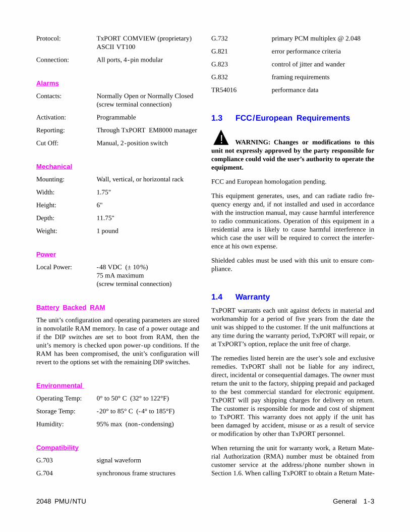
2.5.7 Switch S6 (Bit Rate Selection)
DIP Switch S6 is used to select the bit rates for the USEPTT, and the Supervisory ports. The national bit ‘Pass’ ‘Select’ option is also included on this switch.
Position S6-7: National bit, Dn = Pass, Up = Select.
Position S6-8: Select ‘Dn’ (0) or ‘Up’ (1) for National Bitdata (only if position S6-7 is set for ‘Select’).
2.5.8 Switch S7 (Address)
DIP switch S7 is used to provide up to 250 unique uaddresses. TxPORT’s EM8000 element manager recognaddresses from 1 to 250.
Switch S7 is an 8-position switch with positions labeledthrough 8. The #1 position represents the least significbit (LSB) and the #8 position represents the most significbit (MSB) of the binary code. The eight switches are set tbinary address code in the range of 1 to 250.
S5-5 S5-8 CRC4 Configuration NET CRC
DTE CRC
Dn Dn CRC ON, Insert CRC OFF ON ON
Dn Up CRC ON, Insert CRC ON ON ON
Up Dn CRC OFF, Insert CRC OFF OFF OFF
Up Up CRC OFF, Insert CRC ON ON OFF
S5-6 S5-7 AIS / Keep Alive
Dn Dn AIS is unframed all ones
Dn Up AIS is framed all ones (only active toward network)
Up Dn Line Loop Back (LLB)
Up Up N / A
Pos 1.2 kb/s 2.4 kb/s 9.6 kb/s 19.2 kb/s
SUPV 1 Dn Dn Up Up
2 Dn Up Dn Up
USER NMS
3 Dn Dn Up Up
4 Dn Up Dn Up
PTTNMS
5 Dn Dn Up Up
6 Dn Up Dn Up
7654321 8
Dn
Up
SwitchS6
Sup
ervi
sory
Sup
ervi
sory
US
ER
NM
S
US
ER
NM
S
PT
TN
MS
PT
TN
MS
Nat
’lB
it
Nat
’lB
it
7654321 8
1 2 4 8 16
32
64
128
LSB MSBBinary values
Dn
Up
SwitchS7
2-4 Installation 2048 PMU/NTU

ce.ionur-s to
enssedk
tion0
ts.
As orn-inal
e
geraheny
agesr to
thec.
2.6 Equipment Connection
The equipment physical interface for both the stand-aloneunit and the chassis mounted unit is a standard RJ48C 8-pinmodular jack. A DB15 backplane is also an option for theequipment interface. The pinout assignments are as follows:
NOTE: For 75 ¾ DB15 operation, the following pinsmust be connected together: pins 2 & 9; pins 4 & 11.For 120 ¾, leave as specified.
2.7 Network Connection
The network physical interface for both the stand-alone unitand the chassis mounted unit is a standard RJ48C 8-pinmodular jack. A DB15 backplane is also an option for thenetwork interface. The pinout assignments are shown in thefollowing table.
2.8 Network Management
The 2048 PMU provides several means for user interfaUsing the configuration switch settings described in Sect2.5, the PMU may be configured and operated without fther interface. However, this mode does not allow accesmany of the capabilities of the unit.
For full software control and access to information, thPMU has 3 ports which provide management functio(SUPV, USER, and PTT ports). These ports may be ufor a VT100 terminal interface or for an EM8000 networmanager interface.
An element may be accessed by using an RS232 connecfrom the serial port of the computer running the EM800program to the element’s SUPV, USER, or PTT porThese ports are described in the following paragraphs.
2.8.1 Supervisory Port
The front panel ‘SUPV’ port serves several functions. modem may be connected to this port for remote accesuse of the COA (call on alarm) feature. A computer conected to the SUPV port can access the embedded ‘terminterface’ firmware for PMU software control (refer to th‘Terminal Operations’ chapter).
For cabling convenience, the EM8000 element manamay be directly connected to the ‘SUPV’ port. When group of elements is connected in an NMS chain, tEM8000 may be connected to the supervisory port of aone of the elements. This element can then route messonto the NMS chain to reach the other elements. RefeSection 2.8.2 for more information on the EM8000.
The SUPV port is an independent serial interface into unit and connecting to it does not interrupt NMS port traffi
Pin RJ48 Interface Pin DB15 Interface
1 Data Out 1 Data In
2 Data Out 2 Frame Ground
3/6 Not Used 3 Data Out
4 Data In 4 Frame Ground
5 Data In 9 Data In
7/8 Chassis Ground 11 Data Out
Pin RJ48 Interface Pin DB15 Interface
1 Data In 1 Data Out
2 Data In 2 Not Used
3/6 Not Used 3 Data In
4 Data Out 4 Not Used
5 Data Out 9 Data Out
7/8 Chassis Ground 11 Data In
Figure 2-2 2048 Rear Panel with DB15 Connector
Installation 2-52048 PMU/NTU
8
15
1
9
1
9
8
15
IN OU
T
US
ER
1 2 3 4 5 6
IN OU
T
PT
T
EQPT
NET
Power/Alarm
6 1 6 1
r ace
y to
ive’
d
ion orin
ts.
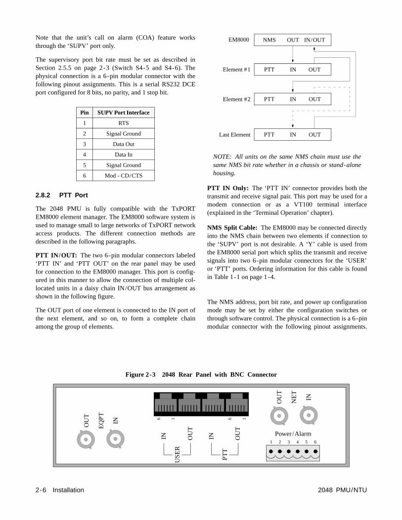
Note that the unit’s call on alarm (COA) feature workthrough the ‘SUPV’ port only.
The supervisory port bit rate must be set as describedSection 2.5.5 on page 2-3 (Switch S4-5 and S4-6). Tphysical connection is a 6-pin modular connector with tfollowing pinout assignments. This is a serial RS232 DCport configured for 8 bits, no parity, and 1 stop bit.
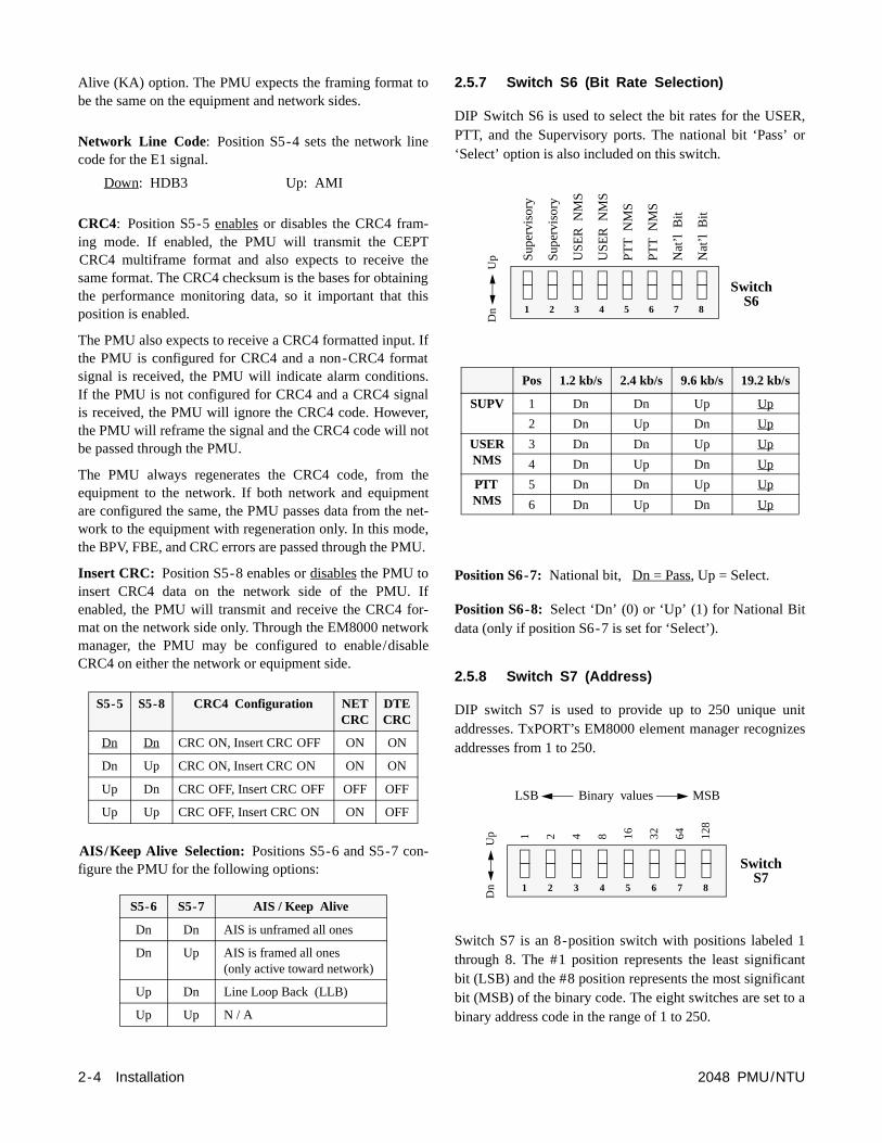
2.8.2 PTT Port
The 2048 PMU is fully compatible with the TxPORTEM8000 element manager. The EM8000 software systemused to manage small to large networks of TxPORT netwaccess products. The different connection methods described in the following paragraphs.
PTT IN/OUT: The two 6-pin modular connectors labele‘PTT IN’ and ‘PTT OUT’ on the rear panel may be usefor connection to the EM8000 manager. This port is confured in this manner to allow the connection of multiple colocated units in a daisy chain IN/OUT bus arrangementshown in the following figure.
The OUT port of one element is connected to the IN portthe next element, and so on, to form a complete chamong the group of elements.
Pin SUPV Port Interface
1 RTS
2 Signal Ground
3 Data Out
4 Data In
5 Signal Ground
6 Mod - CD/CTS
2-6 Installation
OU
T
EQ
PT
IN
IN OU
T
US
ER
6 1
s
inheheE
isorkare
ddig-l-
as
ofain
NOTE: All units on the same NMS chain must use thesame NMS bit rate whether in a chassis or stand-alonehousing.
PTT IN Only: The ‘PTT IN’ connector provides both thetransmit and receive signal pair. This port may be used fomodem connection or as a VT100 terminal interfa(explained in the ‘Terminal Operation’ chapter).
NMS Split Cable: The EM8000 may be connected directlinto the NMS chain between two elements if connectionthe ‘SUPV’ port is not desirable. A ‘Y’ cable is used fromthe EM8000 serial port which splits the transmit and recesignals into two 6-pin modular connectors for the ‘USERor ‘PTT’ ports. Ordering information for this cable is founin Table 1-1 on page 1-4.
The NMS address, port bit rate, and power up configuratmode may be set by either the configuration switchesthrough software control. The physical connection is a 6-pmodular connector with the following pinout assignmen
IN OUTPTT
IN OUTPTT
Element #1
Element #2
OUT IN/OUTNMSEM8000
IN OUTPTTLast Element
Figure 2-3 2048 Rear Panel with BNC Connector
2048 PMU/NTU
IN OU
T
PT
T
1 2 3 4 5 6
Power/Alarm
OU
T
NE
T
IN
6 1

i-ach a
red on
in
uto--rom
This port is a serial RS232 DCE port configured for 8 bits,no parity, and 1 stop bit.
2.8.3 User Port
The USER port (labeled ‘USER – IN/OUT’) is located onthe rear panel. The function of this port is identical to that ofthe PTT port with the following exception. The USER portdoes not allow the clearing of PTT data and the PTT portdoes not allow clearing the USER data. This is explainedfurther in Section 4.4 on page 4-5. The physical connectionis a 6-pin modular connector with the following pinoutassignments.
2.8.4 Chassis Network Management
The operation of the EM8000 in the 12-slot chassis is simlar to the stand-alone operation. Within the chassis, eelement is physically connected to the next element indaisy chain fashion. Signals from all modules are gatheand presented on consolidated 6-pin modular connectorsthe rear panel, labeled ‘NMS IN’ and ‘NMS OUT’. Thefront panel ‘SUPV’ port operates in the same fashion asthe stand-alone unit.
When used in the chassis, the communications bus is amatically tied into each unit, allowing single point interfacing to the chassis. Cards may be inserted and removed f
Pin PTT In PTT Out
1 Not Used Not Used
2 Signal Ground Signal Ground
3 Data Out Data Out
4 Data In Not Used
5 Signal Ground Signal Ground
6 Not Used Not Used
Pin USER In USER Out
1 Not Used Not Used
2 Signal Ground Signal Ground
3 Data Out Data Out
4 Data In Not Used
5 Signal Ground Signal Ground
6 Not Used Not Used
Figure 2-4 75 ¾ Jumper Configuration
Installation 2-72048 PMU/NTU
J12
J13
J14
J15
J16
J4
J5J6
J7J8
J12
J13
J14
J15
J16
J4
J5J6
J7J8
Front
Network
Equipment
Front
Network
Equipment
NO NC
J18
NO NC
J18
Rear Rear

he.
e
gemA
re aA
are
wer
om-ctd.
othnd.-
the
rss aentotlyel
are 6-heedsthe
the chassis without rewiring the communications bus. Com-munications are restored by shorting contacts on the back-plane when a slot is vacant.
NOTE: Ensure that Switch S2 is set to the ‘RACK’ posi-tion (refer to Section 2.5.4 on page 2-3).
2.9 Alarm Connection
The stand-alone unit and the chassis modular unit providerear panel alarm relay contacts. These dry (isolated) alarmcontacts permit connection to a remote indicating device.
2.9.1 Stand-alone Unit
The connection for the stand-alone unit is made on pins 5and 6 of the Alarm/Power connector as shown in Table 2-1.
Table 2-1 Alarm/Power Connection
Pin 5 is configured to operate in either a normally open(NO) or normally closed (NC) mode as determined by thesetting of the alarm relay jumper shown below. Jumper J18is located on the circuit board.
‘NO’ and ‘NC’ refer to the contact’s relationship to thecommon contact under a ‘no alarms’ condition. Move thejumper to NC for normally closed operation (opens onalarm) or to NO for normally open operation (closes onalarm). Make connections to the contacts using 20-gaugestranded wire (or similar). Contacts are rated at 0.3 AmpAC or 1.0 Amp DC.
2.9.2 Chassis Assembly
Alarm conditions from all modules in the chassis are busedtogether in parallel and are presented on a single set ofalarm relay contacts which permit connection to a remoteindicating device. When connected, Pins 3 and 4 on terminal
strip TB1 operate in a normally open mode. Refer to t1051-2 Chassis Configuration Guide for more information
NOTE: All modules in a common chassis must use thnormally open contact mode.
Make connections to the alarm contacts using 20-gaustranded wire (or similar). The contacts are rated at 120 AC or 120 mA DC.
2.10 Power Connection
The stand-alone unit and the modular chassis unit requi-48 VDC power source that is capable of supplying 75 mcurrent. Power supplies are available from TxPORT and listed in Table 1-1 on page 1-4.
Connect the ground lead before applying powerto the unit.
2.10.1 Stand-alone Unit
The power source is connected to pins 1 and 3 of the Poand Alarm terminal as shown in Table 2-1.
Connect a chassis ground lead (18- to 20-gauge is recmended) to the ‘Frame Ground’ terminal (pin 4). Connethe other end of this lead to an appropriate facility grounOften, the 48 VDC return is also ground. In that case, breturn and ground leads should be connected to grouConnect the -48 VDC lead to the ‘-48 VDC’ terminal (18to 20-gauge recommended). Connect the return lead to‘48 VDC return’ terminal.
When power is applied to the unit, the front panel indicatoflash for approximately 10 seconds as the unit executeself-test function. If an ambiguous configuration has beprogrammed, the front panel indicators will continue flash after the self-test is completed. If the unit is correcconfigured, the green ‘STATUS’ indicator on the front panshould light.
2.10.2 Chassis Assembly
When operating the 2048 in the 12-slot chassis, all units powered by -48 VDC sources which are connected to theposition terminal strip TB2 on the rear of the chassis. Tchassis is designed with two power buses. The ‘A’ bus fethe odd slots (1, 3, 5, 7, 9, and 11). The ‘B’ bus feeds even slots (2, 4, 6, 8, 10, and 12).
Pin Function
1 48 VDC return
2 Signal Ground
3 -48 VDC
4 Frame Ground
5 Alarm Contact
6 Alarm Common
J18 NO
NCALM
!
2-8 Installation 2048 PMU/NTU

2048 PMU
1
1325
14
HighSpeedDTE12
HiSpDT1
( B )NMSIN
T1DTE12
TDT1
T1NET12
TNE1
8 1
16
8 1
TB1 - 2 3 41
Figure 2-5 120 ¾ Jumper Configuration
Rack and19" or 23" MultipleLine Chassis Mounting Hardware
Unit 1 Unit 2 Unit 3 Unit 4 Unit 5 Unit 6 Unit 7 Unit 8 Unit 9 Unit 10 Unit 11 Unit 12
Figure 2-6 Model 1051-2 Chassis, Front View
Installation 2-9/NTU
( A )
ENET
gheedE
1
HighSpeedDTE10
HighSpeedDTE
1
HighSpeedDTE
2
HighSpeedDTE
3
HighSpeedDTE
4
HighSpeedDTE
5
HighSpeedDTE
6
HighSpeedDTE
7
HighSpeedDTE
8
HighSpeedDTE
9
NMSOUT
( A )NMSIN
1E
1
T1DTE10
T1DTE
9
T1DTE
8
T1DTE
7
T1DTE
6
T1DTE
5
T1DTE
4
T1DTE
3
T1DTE
2
T1DTE
1
TB2 - 2 3 4 5 61
1 - EXT CLK2 - EXT CLK3 - ALARM RING
TB14 - ALARM TIP5 - SIG GND
1 - +48V RTN (B)2 - FRAME GND3 - -48V IN (B)
4 - -48V IN (A)5 - SIG GND6 - +48V RTN (A)
TB2
1T
1
T1NET10
T1NET
9
T1NET
8
T1NET
7
T1NET
6
T1NET
5
T1NET
4
T1NET
3
T1NET
2
T1NET
1
( B )NMSOUT
5
RedundantPowerBoard

Figure 2-7 Model 1051-2 Chassis, Rear View
2-10 Installation 2048 PMU/NTU

Connect a ground lead (18- to 20-gauge) to the terminalmarked ‘Frame Ground’ on TB2, pin 2. Connect the otherend of this lead to an appropriate facility ground.
The following three modes of powering the chassis areavailable:
Redundant Power Source: The chassis is shipped with aredundant power board installed on power connector TB2.This board allows the connection of two independent -48VDC supplies operated in a redundant mode. All slots in thechassis are powered from the combined input of the A and Bpower supplies. If either supply fails, the other will powerthe entire chassis.
To operate in the redundant power mode, connect the A bus“-48 V IN (A)” and “+48 V RTN (A)” terminals on theredundant power board to the corresponding terminals ofpower supply A. Connect the B bus “-48 V IN (B)” and“+48 V RTN (B)” terminals to the corresponding terminalsof power supply B.
Single Power Source: When using a single power source,simply connect the A bus “-48 V IN (A)” and “+48 V RTN(A)” terminals on the redundant power board to the corre-sponding terminals of power supply A. This is essentiallythe same as the redundant configuration with power supplyB not operational.
If not using the redundant power board, the A bus and the Bbus must be connected together on the rear of the chassiswith a jumper (pin 3 to pin 4 and pin 1 to pin 6).
Dual Power Source: When using a dual independent powersupply, one -48 VDC source feeds the A bus while another -48 VDC source feeds the B bus. First, remove the redundantpower board. Connect the A bus “48 V Return” and “-48VDC” terminals to the corresponding terminals of powersupply A (to power the odd numbered slots). Connect the Bbus “48 V Return” and “-48 VDC” terminals to the corre-sponding terminals of power supply B (to power the evennumbered slots).
NOTE: Each PMU requires a 75 mA current. Ensurethat the proper fuse size is used. Refer to the 1040Power Shelf configuration guide.
Installation 2-112048 PMU/NTU

BV/CR/FE
LOCFAR
ACO SW
ACO
LOS/LOFAISREM ALMLOC ALM
NET
DTE
TST
LLBPLBTSTERR
5
1
7
90
6
8234
FRMNET
MON
TODTE
TONET
MON
FRMDTE
forern
ter) in
n-hen-fer
rm19ks,hsd to
or isick
nfrmanel
sger
-ic.
n
2048 PMU/NTU Front Panel
3
SW1
4
56789
10111213
14
15
2
16
17
2048PMU/NTU
T R A N S P O R T
®
1
SUPV 6
1
Operation
3.0 Introduction
This chapter contains the general operation instructions the TxPORT 2048 front panel. The unit is operated eithmanually or through software control. Manual operatioconsists of using the front panel (described in this chapand the circuit board configuration switches (describedthe Installation chapter).
The Terminal Operation chapter covers the firmware cotrolled Terminal Interface program, which gives the user tmaximum amount of control. The unit may also be cotrolled using the TxPORT EM8000 element manager (reto the EM8000 reference manual).
3.1 Front Panel Descriptions
The 2048 PMU uses LED indicators to convey major alaconditions and looping status. The front panel contains LED indicators, 2 test switches, a set of bantam test jacand a supervisory port connector. The following paragrapdescribe these controls and indicators and are referencethe illustration on this page.
3.1.1 General Status Indicators
1) STATUS: The unit has two LED indicators on thefront panel bezel that are exposed whether the access doopen or closed. These general status LEDs provide a qucheck of the unit’s operating condition (Go or No Go).
If neither LED is lit, the unit is not powered. If the greeLED is lit, the unit is powered and functioning normally. Ithe red LED is lit, there is a line fault which exceeds alathresholds or another type of unit failure. The problem cbe isolated by further examination of the other front panLEDs as described below.
2) Activity Indicators: These two small, recessed LEDare provided to indicate supervisory and network manaport activity.
3.1.2 Alarm Controls and Indicators
3) ACO: This red LED lights whenever the ‘alarm cuoff’ switch is placed in the left ‘ON’ position. It indicatesthat the alarm relay contacts are disabled.
4) ACO SW: The ‘alarm cut off’ switch controls thealarm relay circuitry. If the switch is placed in the left ‘ONposition, this circuitry is deactivated. The right ‘OFF’ postion enables the contacts to report alarm conditions.
2048 PMU/NTU
t
’i-
5) BV/CR / FE: This LED lights 1 second for each second with an occurrence of bipolar violations (BPV), cyclredundancy check (CRC) errors, or frame bit errors (FBE)
6) LOS/OOF: This red LED blinks with loss of signal(LOS) from the network or DTE. It lights constantly whean Out of Frame (OOF) condition is detected.
Operation 3-1
si-
r-d
lineveoertily.
cttusthisn-
enethe
- to
7) AIS: This red ‘alarm indication signal’ lights if theselected AIS condition is detected from the network orequipment. Refer to Section 2.5.6 on page 2-3.
8) REM ALM: This LED lights constantly when aremote (yellow) alarm signal is received.
9) LOC ALM: This LED lights when a local alarmexceeding alarm thresholds exists.
Refer to Section 4.6.2 on page 4-10 for more informationon alarm thresholds.
3.1.3 Test Controls and Indicators
10) LLB: This red LED lights to indicate that the unit is ina line loopback condition.
11) PLB: This red LED lights to indicate that the unit is ina payload loopback condition.
12) TST: This red LED lights constantly if the PMU hasbeen placed in a local or remote test loop. It blinks while aloop or unloop code is being sent.
13) ERR: This red LED lights 1 second when BERT erroror sync loss is detected. It lights continuously to indicatehigh bit error rates or loss of pattern sync. A loss of patternsync may be due to the far end not responding to the IBLC.
14) Test Switch: This switch (FAR/LOC) is used for localtesting. Refer to Section 3.2.1 for more information.
15) Test Access Jacks: These bantam jacks are providedfor access to the E1 line on the DTE side of the PMU. Referto Section 3.2.2.
16) Supervisory Port: The supervisory jack providesdirect terminal access to control the unit and gather status/facility performance data. Refer to Section 3.2.3.
17) Pattern Select: This rotary switch determines theBERT pattern sent by the unit when the test switch is in the‘FAR’ or ‘LOC’ position. Refer to Section 3.2.4.
3.2 Front Panel Testing
The previous section gave a brief description of each frontpanel control and LED indicator. This section explains thefront panel test functions. Testing may also be performedusing software control from the EM8000 element manageror the Terminal Interface program.
3.2.1 Test Switch
This switch (labeled ‘Far/Loc’) is used for local testing.When in the ‘Far’ position, the unit sends 5 seconds ofIBLC (inband loop codes), then switches to the test patternselected by rotary switch SW1 (Pattern Select). When trans-mitting IBLC, the test LED blinks. When transmitting a test
pattern, it lights continuously. The ‘ERR’ LED lights for 1second when a bit error or sync loss is detected.
When the test switch is returned to the ‘normal’ center potion, the unit sends 5 seconds of loop down code (100 ) andthen returns to its normal operating mode.
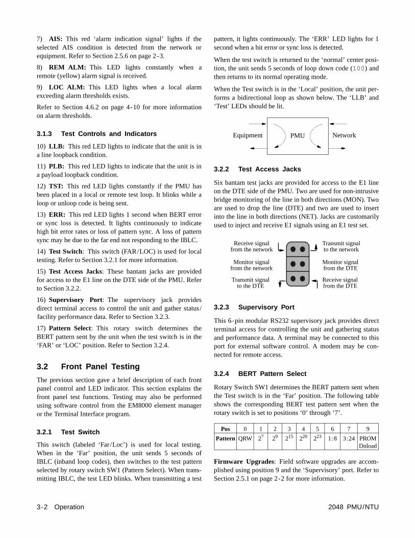
When the Test switch is in the ‘Local’ position, the unit peforms a bidirectional loop as shown below. The ‘LLB’ an‘Test’ LEDs should be lit.
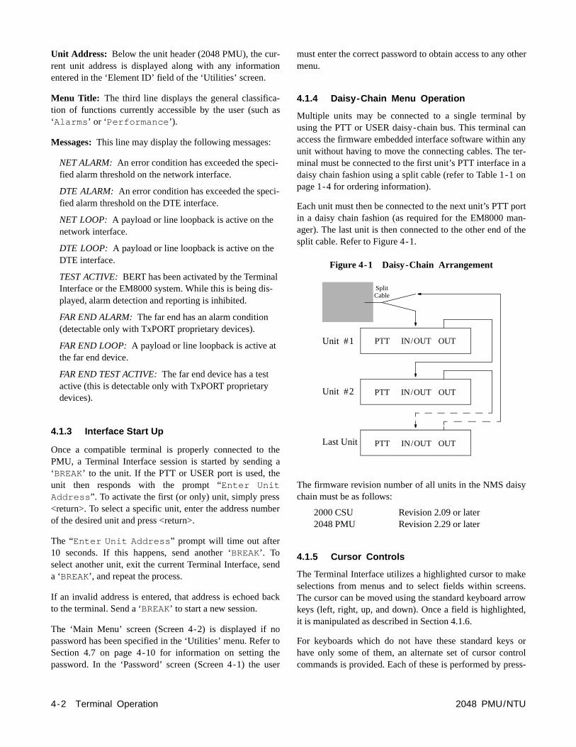
3.2.2 Test Access Jacks
Six bantam test jacks are provided for access to the E1 on the DTE side of the PMU. Two are used for non-intrusibridge monitoring of the line in both directions (MON). Tware used to drop the line (DTE) and two are used to insinto the line in both directions (NET). Jacks are customarused to inject and receive E1 signals using an E1 test set
3.2.3 Supervisory Port
This 6-pin modular RS232 supervisory jack provides direterminal access for controlling the unit and gathering staand performance data. A terminal may be connected to port for external software control. A modem may be conected for remote access.
3.2.4 BERT Pattern Select
Rotary Switch SW1 determines the BERT pattern sent whthe Test switch is in the ‘Far’ position. The following tablshows the corresponding BERT test pattern sent when rotary switch is set to positions ‘0’ through ‘7’.
Firmware Upgrades: Field software upgrades are accomplished using position 9 and the ‘Supervisory’ port. ReferSection 2.5.1 on page 2-2 for more information.
Pos 0 1 2 3 4 5 6 7 9
Pattern QRW 27 29 215 220 223 1:8 3:24 PROMDnload
PMUEquipment Network
Receive signalfrom the DTE
Transmit signalto the network
Transmit signalto the DTE
Receive signalfrom the network
Monitor signalfrom the network
Monitor signalfrom the DTE
3-2 Operation 2048 PMU/NTU

toho,
om-heare
.
lefttheis-mi- tohis
-enddard
as
‘
then
s-nc-
Terminal Operation
4.0 Introduction
This chapter describes the screens and menus associatedwith the TxPORT 2048 PMU Terminal Interface, which is afirmware application program embedded inside the unit. Theinterface allows control and monitoring of the unit through aserial terminal, using any of the serial ports located on thefront and rear panels.
4.1 System Description
The Terminal Interface requires an ANSI compatible VT100terminal (ASCII), or a computer running an ANSI terminalemulation program. The Terminal Interface utilizes theASCII ‘Break’ and ‘Escape’ functions, which are imple-mented differently with various terminal emulation pro-grams. The documentation supplied with the emulationprogram should be consulted for further reference.
The unit has three serial interface RS232 ports. Any of theseports may be used for the Terminal Interface or as a connec-tion to the EM8000 network manager. Two of these ports arepairs of daisy chain type rear panel connectors labeled ‘PTTIN/OUT ’, ‘ PTT OUT’ and ‘USER IN/OUT ’, ‘ USER OUT’.The other port is located on the front panel and is labeled‘SUPV’. Serial bit rates of 1200, 2400, 9600, or 19200 maybe selected using option switches (refer to Section 2.5.7 onpage 2-4).
4.1.1 Modem Compatibility
The 2048 PMU Terminal Interface supports the use of an‘AT’ command set compatible modem on any of the unit’s
serial RS232 ports. The modem should be optionedignore DTR, enable auto answer, inhibit command ecand return verbal result codes.
NOTE: If the user calls the 2048 PMU and sends the‘BREAK’ command before receiving the ‘CONNECT’message, the modem will hang up.
4.1.2 Screen Components
Terminal Interface screens have several components cmon to all screens and will be discussed individually in tfollowing paragraphs. These common screen elements shown on the ‘Password Screen’ (see Screen 4-1 below)
Device Type and Revision: The device type (2048 PMU)and the revision control numbers are shown in the upper corner. The first number is the hardware revision and second number is the software revision. Information is dplayed for the near end unit (connected directly to the ternal) on the top line, and for the far end unit (connectedthe network E1 interface) on the second line. Refer to tinformation when contacting the factory with inquiries.
The far end information is available only for TxPORT products that support a proprietary message set. If the far does not support these messages but does support stan54016 protocol, then the far end information is displayed‘GENERIC 54016 FAR END’. If the far end does notrespond to either proprietary or 54016 messages, then NOFAR END RESPONSE’ will be displayed. If the far end ech-oes the FDL messages transmitted by the near end unit, ‘FAR END LINE LOOP’ is displayed.
Date/Time: The top right corner of the terminal screen diplays the current date and time. The setting of these futions is described in Section 4.7 on page 4-10.
Screen 4-1 Password
Terminal Operation 4-12048 PMU/NTU
2048 PMU x.xx/x.xx 2048 PMU Date MM/DD/YY 2048 PMU x.xx/x.xx (Unit Address: xxx) Time HH:MM:SS
------------------------------- PASSWORD SCREEN --------------------------------
Enter Password: (**********)
Start Date: MM/DD/YY
Start Time: HH:MM:SS
----------------------------------- Messages -----------------------------------
ther
byananyer- a
on
ortn-
the
y
kens.rrowd,
ortrolss-
Unit Address: Below the unit header (2048 PMU), the cur-rent unit address is displayed along with any informationentered in the ‘Element ID’ field of the ‘Utilities’ screen.
Menu Title: The third line displays the general classifica-tion of functions currently accessible by the user (such as‘Alarms ’ or ‘Performance ’).
Messages:This line may display the following messages:
NET ALARM: An error condition has exceeded the speci-fied alarm threshold on the network interface.
DTE ALARM: An error condition has exceeded the speci-fied alarm threshold on the DTE interface.
NET LOOP: A payload or line loopback is active on the network interface.
DTE LOOP: A payload or line loopback is active on the DTE interface.
TEST ACTIVE:BERT has been activated by the Terminal Interface or the EM8000 system. While this is being dis-played, alarm detection and reporting is inhibited.
FAR END ALARM:The far end has an alarm condition (detectable only with TxPORT proprietary devices).
FAR END LOOP:A payload or line loopback is active at the far end device.
FAR END TEST ACTIVE:The far end device has a test active (this is detectable only with TxPORT proprietary devices).
4.1.3 Interface Start Up
Once a compatible terminal is properly connected to thePMU, a Terminal Interface session is started by sending a‘BREAK’ to the unit. If the PTT or USER port is used, theunit then responds with the prompt “Enter UnitAddress ”. To activate the first (or only) unit, simply press<return>. To select a specific unit, enter the address numberof the desired unit and press <return>.
The “Enter Unit Address ” prompt will time out after10 seconds. If this happens, send another ‘BREAK’. Toselect another unit, exit the current Terminal Interface, senda ‘BREAK’, and repeat the process.
If an invalid address is entered, that address is echoed backto the terminal. Send a ‘BREAK’ to start a new session.
The ‘Main Menu’ screen (Screen 4-2) is displayed if nopassword has been specified in the ‘Utilities’ menu. Refer toSection 4.7 on page 4-10 for information on setting thepassword. In the ‘Password’ screen (Screen 4-1) the user
must enter the correct password to obtain access to any omenu.
4.1.4 Daisy-Chain Menu Operation
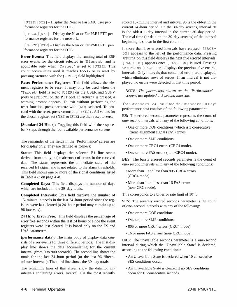
Multiple units may be connected to a single terminal using the PTT or USER daisy-chain bus. This terminal caccess the firmware embedded interface software within unit without having to move the connecting cables. The tminal must be connected to the first unit’s PTT interface indaisy chain fashion using a split cable (refer to Table 1-1page 1-4 for ordering information).
Each unit must then be connected to the next unit’s PTT pin a daisy chain fashion (as required for the EM8000 maager). The last unit is then connected to the other end ofsplit cable. Refer to Figure 4-1.
Figure 4-1 Daisy-Chain Arrangement
The firmware revision number of all units in the NMS daischain must be as follows:
2000 CSU Revision 2.09 or later 2048 PMU Revision 2.29 or later
4.1.5 Cursor Controls
The Terminal Interface utilizes a highlighted cursor to maselections from menus and to select fields within screeThe cursor can be moved using the standard keyboard akeys (left, right, up, and down). Once a field is highlighteit is manipulated as described in Section 4.1.6.
For keyboards which do not have these standard keyshave only some of them, an alternate set of cursor concommands is provided. Each of these is performed by pre
Unit #1 IN/OUT OUTPTT
IN/OUT OUTPTT
IN/OUT OUTPTT
Unit #2
Last Unit
SplitCable
4-2 Terminal Operation 2048 PMU/NTU

ptsgentan
w>ar-ays
at
theuser
t
)
c-nu,
hissingees-the
ing a letter key while holding down the <Ctrl> key. Alter-nate commands may be freely mixed with the keyboardcommands at the user’s discretion. The alternate commandkeys are listed in the following table.
4.1.6 Field Types
Each screen is made up of fields. The two basic types are‘user selectable’ and ‘display only’. If the highlighted cursorcan be moved to a field, it is a ‘user selectable’ field. Allother fields are ‘display only’. User selectable fields allowfor changes to be made or commands to be executed.
Fields without brackets or parenthesis are ‘display only’fields. They cannot be changed on the screen. Most ‘userselectable’ fields are enclosed in brackets or parenthesis andare described in the following paragraphs. Any exceptionsare noted in the appropriate section of this manual.
Fields enclosed in brackets [ ] offer the user a list of selec-tions from which to choose. The selections may be toggledby pressing the spacebar. Each time the spacebar is pressed,a new item appears. When the appropriate choice is dis-played, press <return> to select it.
Fields enclosed in parenthesis ( ) are manipulated by oneof the following two methods:
1) Pressing <return> on such fields as (Reset ) and(Start Test ) simply execute the function.
2) The most common type of field in parenthesis accetyped input in the form of letters and/or numbers. Typincharacters when the field is highlighted causes the currentry to be replaced with the new characters. To edit existing entry rather than replace it, press the <right arrokey to move the cursor to the point that needs editing. Chacters may then be inserted or deleted. Typed data is alwinserted rather than typed over. If the field is full, though,least one character must be deleted to add another.
Many fields of this type may also be toggled by pressing <spacebar>. Other fields are range checked, where the is not allowed to exit with an illegal value set.
NOTE: Any changes to fields on a screen that have nobeen activated by pressing <return> will be discarded.
NOTE: Any screen may be redisplayed (or refreshedby pressing <Ctrl - U>.
4.2 Main Menu Screen
The ‘Main Menu’ screen (refer to Screen 4-2) lists the funtional menus accessible by the user. To activate any mehighlight the desired selection and press <return>. Tmenu and any subsequent menu may be exited by pres<esc>. If the ‘Main Menu’ is exited, the Terminal Interfacprogram terminates. This is a valid way to end a user ssion. If any other menu is exited, the user is returned to previous screen.
NOTE: If the keyboard is inactive for a 10-minuteperiod, the Terminal Interface logs off automatically. Tomanually log off, press <esc> from the ‘Main Menu’.
Keyboard Command Alternate Command
< left arrow > < Ctrl - S >
< right arrow > < Ctrl - D >
< up arrow > < Ctrl - E >
< down arrow > < Ctrl - X >
< backspace > < Ctrl - H >
< delete > < Ctrl - Z >
Screen 4-2 Main Menu
Terminal Operation 4-32048 PMU/NTU
2048 PMU x.xx/x.xx 2048 PMU Date MM/DD/YY 2048 PMU x.xx/x.xx (Unit Address: xxx) Time HH:MM:SS
------------------------------------- MAIN -------------------------------------
Alarms
Performance
Maintenance
Configuration
Utilities
----------------------------------- Messages -----------------------------------

ds
s.
-d to
5er-d.
e).
aterny
h
r
The menu structure (Figure 4-2) shows all the screensaccessible from the ‘Main Menu’.
Figure 4-2 Menu Structure
4.3 Alarms Screen
The ‘Alarms’ screen (Screen 4-3) is used to view the currentalarm status of the network and DTE lines. The fields aredescribed as follows:
Element: Pressing the <spacebar> toggles this field forselection of either the ‘NEAR’ or ‘FAR’ unit. ‘NEAR’ refersto the unit to which the terminal is connected. ‘FAR’ refersto the unit at the other end of the network E1 span.
NET /DTE Alarms : These status lines display the selecteelement’s current network/DTE signal alarm state. Alarmare determined by the following user selectable threshold
Table 4-1 Alarm Indications
(alarm status): The main body of the ‘Alarms’ screen displays the current count for parameters that may be usetrigger an alarm.
The ‘Current ’ column shows the total of the preceding 1one-minute intervals. At the end of each one-minute intval, the oldest minute of the 15-minute interval is discarde
The ‘Threshold ’ column shows the values set in th‘Alarm Configuration’ screen (Screen 4-7 on page 4-10Any parameter that has a current value equal to or grethan its non-zero threshold will generate an alarm. Aparameter with a threshold value of ‘0’ is disabled fromgenerating alarms.
Alarm Parameters
Line Parameters
Alarms
MAINMENU
LogOff
LogOn
Performance
Maintenance
Configuration
Utilities
Enhanced 24-Hour
Standard 24-Hour
Standard 30-Day
Enhanced 30-Day
Alarm Description
------- No status is available
None No alarm threshold has been exceeded, althougerrors may exist which do not exceed thresholds.
ERRS Errored Seconds, Severely Errored Seconds, oBipolar Errored Seconds threshold is exceeded.
LOSS Loss Of Signal Seconds threshold is exceeded.
OOFS Out Of Frame Seconds threshold is exceeded.
RAIS Remote Alarm Seconds threshold is exceeded.
AISS Alarm Indication Seconds threshold is exceeded.
UAS Unavailable Seconds threshold is exceeded.
Screen 4-3 Alarms
4-4 Terminal Operation 2048 PMU/NTU
2048 PMU x.xx/x.xx 2048 PMU Date MM/DD/YY 2048 PMU x.xx/x.xx (Unit Address: xxx) Time HH:MM:SS
------------------------------------ ALARMS ------------------------------------
Element: [NEAR]
NET Alarms: NONE DTE Alarms: NONE
Current ThresholdLoss Of Signal Seconds (LOSS): 0 5Errored Seconds (ES): 2 45Severely Errored Seconds (SES): 2 5Unavailable Seconds (UAS): 0 0Out Of Frame Seconds (OOFS): 0 0Remote Alarm Seconds (RAS): 0 0AIS Seconds (AISS): 0 0BPV Seconds (BPVS): 0 0DTE LOS/OOF Seconds (LOSS): 0 5Power Loss Seconds (PLS): 0Reset Alarm Registers: (RESET)

al
ceng
is-ns
cu-valseen
or
eog-
NOTE: The parameters shown on the Alarms Screenare updated at five second intervals.
Power Loss Seconds: This field displays the number ofseconds that the PMU has been without power since thisvalue was last cleared.
Reset Alarm Registers: Pressing <return> on (RESET)zeros the value of all ‘Current ’ alarm parameters, butdoes not affect 24-hour or 30-day performance registers.
4.4 Performance Screens
The ‘Performance’ screens display a detailed history of theerror parameters that are continuously monitored. The Ter-minal Interface provides display of near end or far end per-formance data using the facility data link.
The PMU is equipped with a dual set of performance dataregisters with individual resets that hold line statistics forboth the PTT and user. Each register set provides detailedstatus and performance history for the network and DTEinterfaces. Access to the data registers is provided throughone front and two rear management ports, which providetest, diagnostics, and control over the CEPT E1 network.Access can also be obtained through a data link using anassigned spare national bit.
Both register sets may be viewed from any serial port. ThePTT performance data registers can be cleared only throughthe PTT port. USER registers can only be cleared through
the USER or SUPV port. Both registers contain identiccore performance information.
The unit enables downloading of remote site performandata from the far end unit, in all modes of operation, usithe facility data link (user selectable national bits).
The system has four ‘Performance’ screens. The ‘STAN-DARD 24 HOUR’ and the ‘ENHANCED 24 HOUR’ screensallow the user to view the 24-hour detailed performance htory of the E1 circuit. The only difference in the two screeis in the type of performance data displayed. The ‘STAN-DARD 24 HOUR’ screen is shown in Screen 4-4.
The ‘STANDARD 30 DAY’ and the ‘ENHANCED 30 DAY’screens allow the user to view a 30-day history of a partilar element’s performance. These screens reference interby date rather than by time. To reach each of the four scrtypes, use the <spacebar> to toggle the ‘STANDARD 24HOUR’ field. The other fields are described as follows:
Element: Pressing the <spacebar> toggles this field fselection of either the ‘NEAR’ or ‘FAR’ unit as the source ofperformance data or the target of commands. ‘NEAR’ refersto the unit to which the terminal is connected. ‘FAR’ refersto the unit at the other end of the network E1 span.
Target: This two-part field determines which section of thcircuit is presently displayed. Pressing the <spacebar> tgles the following options:
[USER] [NET] – Display the Near or Far PMU user per-formance registers for the network.
Screen 4-4 Performance
Terminal Operation 4-52048 PMU/NTU
2048 PMU x.xx/x.xx 2048 PMU Date MM/DD/YY 2048 PMU x.xx/x.xx (Unit Address: xxx) Time HH:MM:SS
--------------------------------- PERFORMANCE ----------------------------------
Element: [NEAR] Status: OKTarget: [USER][NET] Completed Days: 30Error Events: 65535 (RESET) Completed Intervals: 96(RESET PERFORMANCE REGS) 24 Hr.% Error Free: 98.2
[STANDARD 24 HOUR]
411 0 0 0 2 3 3 24 Hour 10 0 0 2 3 0 30 Day 30 10 20 12 2 13
PAGE-UP -------------------------------------------------------------------Time Interval ES UAS BES SES LOFC CSS
PAGE-DN ------------------------------------------------------------------- 13:45 6 1 0 0 0 1 0 13:30 7 2 0 0 0 2 0 13:15 8 4 0 0 0 2 0
he 30d.
rval
ingls.
ed,s-
t of
t of
unt
ondd,
[USER] [DTE] – Display the Near or Far PMU user per-formance registers for the DTE.
[TELCO] [NET] – Display the Near or Far PMU PTT per-formance registers for the network.
[TELCO] [DTE] – Display the Near or Far PMU PTT per-formance registers for the DTE.
Error Events: This field displays the running total of ESFerror events for the circuit selected in ‘Element ’ and isapplicable only when ‘Target ’ is set to [USER]. Thiscount accumulates until it reaches 65535 or is reset bypressing <return> with the (RESET) field highlighted.
Reset Performance Registers: This field allows the ele-ment registers to be reset. It may only be used when the‘Target ’ field is set to [USER] on the USER and SUPVports or [TELCO] on the PTT port. If <return> is pressed, awarning prompt appears. To exit without performing thereset function, press <return> with (NO) selected. To pro-ceed with the reset, press <return> on (YES) . All values forthe chosen register set (NET or DTE) are then reset to zero.
[Standard 24 Hour]: Toggling this field with the <space-bar> steps through the four available performance screens.
The remainder of the fields in the ‘Performance’ screen arefor display only. They are defined as follows:
Status: This field displays the selected E1 line statusderived from the type (or absence) of errors in the receiveddata. The status represents the immediate state of thereceived E1 signal and is not related to the alarm thresholds.This field shows one or more of the signal conditions listedin Table 4-2 on page 4-8.
Completed Days: This field displays the number of dayswhich are included in the 30-day totals.
Completed Intervals: This field displays the number of15-minute intervals in the last 24-hour period since the reg-isters were last cleared (a 24-hour period may contain up to96 intervals).
24 Hr.% Error Free: This field displays the percentage oferror free seconds within the last 24 hours or since the eventregisters were last cleared. It is based only on the ES andUAS parameters.
(performance data): The main body of display data con-sists of error events for three different periods: The first dis-play line shows the data accumulating for the currentinterval (from 0 to 900 seconds). The second line shows thetotals for the last 24-hour period (or the last 96 fifteen-minute intervals). The third line shows the 30-day totals.
The remaining lines of this screen show the data for anyintervals containing errors. Interval 1 is the most recently
stored 15-minute interval and interval 96 is the oldest in tcurrent 24-hour period. On the 30-day screens, intervalis the oldest 1-day interval in the current 30-day perioThe real time (or date on the 30-day screens) of the intebeginning is shown in the first column.
If more than five errored intervals have elapsed, [PAGE-DN] appears to the left of the performance data. Press<return> on this field displays the next five errored interva[PAGE-UP] appears once [PAGE-DN] is used. Pressing<return> on [PAGE-UP] displays the previous five erroredintervals. Only intervals that contained errors are displaywhich eliminates rows of zeroes. If an interval is not diplayed, no errors were detected in that time period.
NOTE: The parameters shown on the ‘Performance’screens are updated at 5 second intervals.
The ‘Standard 24 Hour ’ and the ‘Standard 30 Day’performance data consists of the following parameters:
ES: The errored seconds parameter represents the counone-second intervals with any of the following conditions:
• One or more OOF conditions, which is 3 consecutive frame alignment signal (FAS) errors.
• One or more SLIP conditions.
• One or more CRC4 errors (CRC4 mode).
• One or more FAS errors (non-CRC4 mode).
BES: The bursty errored seconds parameter is the counone-second intervals with any of the following conditions:
• More than 1 and less than 805 CRC4 errors (CRC4 mode).
• More than 1 and less than 16 FAS errors (non-CRC mode).
This corresponds to a bit error rate limit of 10-3.
SES: The severely errored seconds parameter is the coof one-second intervals with any of the following:
• One or more OOF conditions.
• One or more SLIP conditions.
• 805 or more CRC4 errors (CRC4 mode).
• 16 or more FAS errors (non-CRC mode).
UAS: The unavailable seconds parameter is a one-secinterval during which the ‘Unavailable State’ is declareaccording to the following conditions:
• An Unavailable State is declared when 10 consecutiveSES conditions occur.
• An Unavailable State is cleared if no SES conditions occur for 10 consecutive seconds.
4-6 Terminal Operation 2048 PMU/NTU

ag
or
ier ut
ondps
OutS),
m
ruit.re,ach
ll
Figure 4-3 Loopbacks
Network
Framer
DTE
Far NET PLB
TARGETPMU
Framer
Far NET LLB
DTE
Framer
Framer
Near NET LLB
Near DTE PLB
Near NET PLB
Near DTE LLB
LOFC: The loss of frame count parameter representscount of ‘Carrier Failure’ condition declarations, accordinto the following criteria:
A carrier failure condition is declared if a LOS or OOF condition persists for 2.5 seconds. For intermittent LOS OOF conditions, the following time integration method isapplied. The decay time (time subtract) slope during a normal signal should be 20% of the rise slope. The carrfailure condition is cleared when 1 second passes withoa LOS or OOF condition occurring.
SS: The slip seconds parameter is the count of one-secintervals during which a frame slip occurred. Frame slioccur only if ‘Internal’ or ‘Network’ clocking is selected.
The ‘Enhanced 24 Hour ’ and ‘Enhanced 30 Day’screens show data for CRC Errored Seconds (CRCES), of Frame Seconds (OOFS), Loss of Signal Seconds (LOSAlarm Indication Signal Seconds (AISS), Remote AlarSeconds (RAS), and Bipolar Violation Seconds (BPVS).
4.5 Maintenance Screen
The ‘Maintenance ’ screen (Screen 4-5) allows the useto perform test and maintenance functions on the E1 circBERT is performed using on-board test facilities. Therefono other test equipment is needed. Actions initiated by efield are detailed in the following paragraphs.
Clear Tests: Pressing <return> on this field clears all tesand any loops that have been initiated.
2048 PMU/NTU
2048 PMU x.xx/x.xx 2048 Far End Line Loop (Unit Address: xxx)
----------------------------- ELEMENT MA
(CLEAR TESTS) (CLEAR ALARMS
Loop: [NET LLB][AIS ] P Unloop: [DTE PLB]
NET Status: OK DTE Status: N/A Near Loops: Far Loops: NET LLB
tsClear Alarms: Pressing <return> on this field causes anear end alarms to be cleared.
Screen 4-5 Maintenance
Terminal Operation 4-7
PMU Date MM/DD/YY Time HH:MM:SS
INTENANCE ------------------------------
Pattern: [QRSS] Test Length: [15 min]
attern Sync: IN SYNC Elapsed Time: 01:15:00
Bit Errors: 5 Errored Seconds: 3 % EFS: 97.5
(STOP TEST ) (RESET ERRORS)
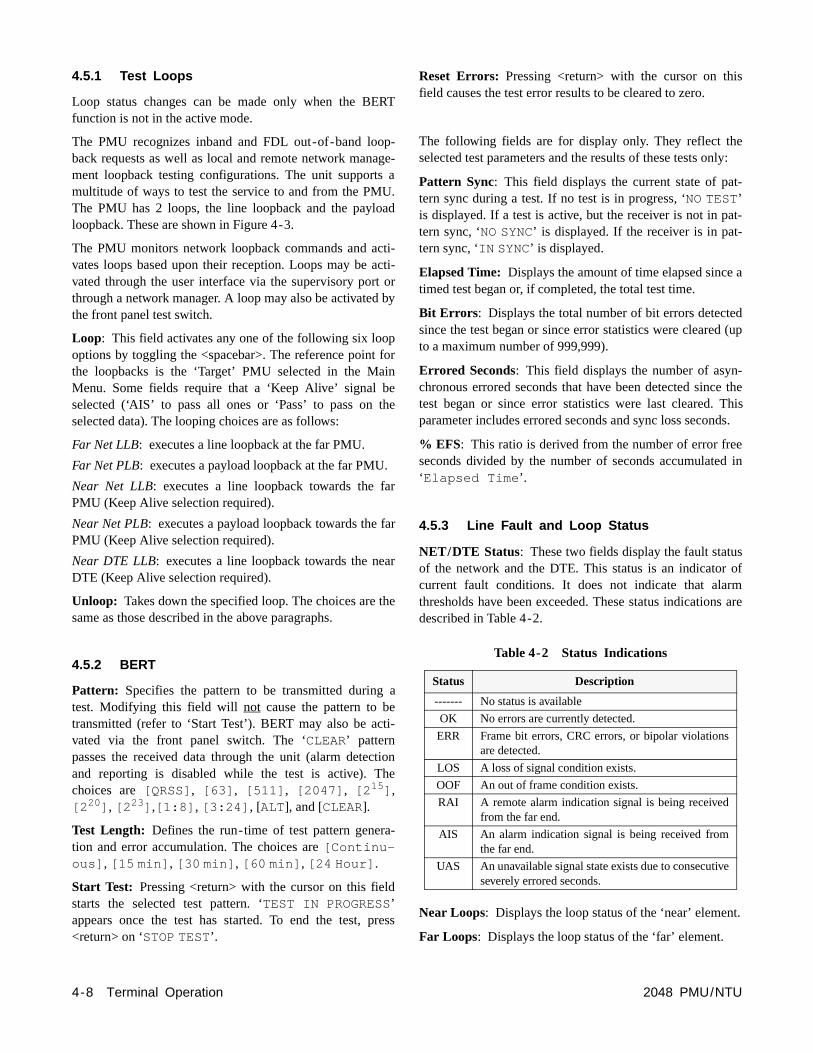
s
ely:
t-
at-
a
d (up
-e thehis
ds.
ed in
sofms are
t.
4.5.1 Test Loops
Loop status changes can be made only when the BERTfunction is not in the active mode.
The PMU recognizes inband and FDL out-of-band loop-back requests as well as local and remote network manage-ment loopback testing configurations. The unit supports amultitude of ways to test the service to and from the PMU.The PMU has 2 loops, the line loopback and the payloadloopback. These are shown in Figure 4-3.
The PMU monitors network loopback commands and acti-vates loops based upon their reception. Loops may be acti-vated through the user interface via the supervisory port orthrough a network manager. A loop may also be activated bythe front panel test switch.
Loop: This field activates any one of the following six loopoptions by toggling the <spacebar>. The reference point forthe loopbacks is the ‘Target’ PMU selected in the MainMenu. Some fields require that a ‘Keep Alive’ signal beselected (‘AIS’ to pass all ones or ‘Pass’ to pass on theselected data). The looping choices are as follows:
Far Net LLB: executes a line loopback at the far PMU.
Far Net PLB: executes a payload loopback at the far PMU.
Near Net LLB: executes a line loopback towards the farPMU (Keep Alive selection required).
Near Net PLB: executes a payload loopback towards the farPMU (Keep Alive selection required).
Near DTE LLB: executes a line loopback towards the nearDTE (Keep Alive selection required).
Unloop: Takes down the specified loop. The choices are thesame as those described in the above paragraphs.
4.5.2 BERT
Pattern: Specifies the pattern to be transmitted during atest. Modifying this field will not cause the pattern to betransmitted (refer to ‘Start Test’). BERT may also be acti-vated via the front panel switch. The ‘CLEAR’ patternpasses the received data through the unit (alarm detectionand reporting is disabled while the test is active). Thechoices are [QRSS] , [63] , [511] , [2047] , [2 15] ,[2 20] , [2 23] ,[1:8] , [3:24] , [ALT], and [CLEAR].
Test Length: Defines the run-time of test pattern genera-tion and error accumulation. The choices are [Continu-ous] , [15 min] , [30 min] , [60 min] , [24 Hour] .
Start Test: Pressing <return> with the cursor on this fieldstarts the selected test pattern. ‘TEST IN PROGRESS’appears once the test has started. To end the test, press<return> on ‘STOP TEST’.
Reset Errors: Pressing <return> with the cursor on thifield causes the test error results to be cleared to zero.
The following fields are for display only. They reflect thselected test parameters and the results of these tests on
Pattern Sync: This field displays the current state of patern sync during a test. If no test is in progress, ‘NO TEST’is displayed. If a test is active, but the receiver is not in ptern sync, ‘NO SYNC’ is displayed. If the receiver is in pat-tern sync, ‘IN SYNC’ is displayed.
Elapsed Time: Displays the amount of time elapsed sincetimed test began or, if completed, the total test time.
Bit Errors : Displays the total number of bit errors detectesince the test began or since error statistics were clearedto a maximum number of 999,999).
Errored Seconds: This field displays the number of asynchronous errored seconds that have been detected sinctest began or since error statistics were last cleared. Tparameter includes errored seconds and sync loss secon
% EFS: This ratio is derived from the number of error freseconds divided by the number of seconds accumulate‘Elapsed Time ’.
4.5.3 Line Fault and Loop Status
NET/DTE Status: These two fields display the fault statuof the network and the DTE. This status is an indicator current fault conditions. It does not indicate that alarthresholds have been exceeded. These status indicationdescribed in Table 4-2.
Table 4-2 Status Indications
Near Loops: Displays the loop status of the ‘near’ elemen
Far Loops: Displays the loop status of the ‘far’ element.
Status Description
------- No status is available
OK No errors are currently detected.
ERR Frame bit errors, CRC errors, or bipolar violationsare detected.
LOS A loss of signal condition exists.
OOF An out of frame condition exists.
RAI A remote alarm indication signal is being receivedfrom the far end.
AIS An alarm indication signal is being received fromthe far end.
UAS An unavailable signal state exists due to consecutiveseverely errored seconds.
4-8 Terminal Operation 2048 PMU/NTU

he
,e
.
d
ctk.ith
illnt
sedhe on
.of
hen.
4.6 Configuration Screens
The two ‘Configuration’ screens allow the user to view andset the configuration parameters for the network elements.When ‘Configuration ’ is selected from the MainMenu, the ‘Line Configuration’ screen appears. The ‘AlarmConfiguration’ screen is accessed by pressing <return> on(GO TO ALARM THRESHOLDS). To send a new configura-tion to the unit, the user must press <return> on one of thefields or exit the screen.
A circuit may be configured either before or after the hard-ware is installed using the option switches or the TerminalInterface. If the unit is to retain the configuration parametersselected through the Terminal Interface on power-up, theoption switches must be set to boot from RAM. Once aPMU is active, its configuration may be changed by thisprogram regardless of the switch settings.
NOTE: The underlined values are the factory defaultparameters stored in ROM.
4.6.1 Line Configuration
The ‘Line Configuration’ screen (Screen 4-6) allows theuser to view and set configuration parameters for the PMUson the E1 circuit. This screen has the following fields, all ofwhich have user selectable options. To send the new lineconfiguration to the unit, either press <return> on one of thefields, change the ‘Element’ selection, or exit the screen.
Element: Pressing the <spacebar> toggles this field forselection of either the [NEAR] or [FAR] unit.
Signalling: The choices are ‘CAS’ (PCM30) and ‘CCS’(PCM31). If CAS is selected and the DTE is using CCS, the
PMU will show a Loss of Frame. If CCS is selected and tDTE is using CAS, the PMU will frame up normally.
NET CRC4: The choices are ‘On’ and ‘Off’. If enabledthe PMU will insert CRC4 information into the frame befordata reaches the network.
DTE CRC4: The choices are ‘On’ and ‘Off’. If ‘ON’, thePMU receives and transmits the CRC4 format to the DTE
Line Code: The choices are ‘HDB3’ and ‘AMI’. Select thesignalling method which is being used on the line.
Keep Alive: The choices are ‘unframed all ones’, ‘frameall ones’, or ‘LLB’ (line loopback towards the network).
National Bit Position: The choices are 1 through 5. Selethe National Bit to be used for composition of the data linThis is the method used by the PMUs to communicate weach other within the framing structure. Selecting ‘1’ wplace the data link in Sa4, bit 4 of the non-frame alignmeword (2 - Sa5, 3 - Sa6, 4 - Sa7, and 5 - Sa8).
National Bits: The choices are ‘Pass’, ‘All ones’, and ‘Allzeros’. ‘Pass’ will pass (as received) any data on the ununational bits. Selecting ‘All ones’ sends all ones on tunused national bits. Selecting ‘All zeros’ sends all zerosthe unused national bits.
Inband Loop: The choices are ‘Enable’ and ‘Disable’‘Disabled’ is used in cases where there is a possibility data being passed which conforms to the loop code. W‘Disabled’, the PMU will not loopback to any loop codeThis is normally ‘Enabled’.
BERT Polarity : Selects the polarity of the ‘1’ bit in theBERT test modes. The choices are ‘NORMAL’ (space = 1) or‘ INVERTED’ (mark = 1).
Screen 4-6 Line Configuration
Terminal Operation 4-92048 PMU/NTU
2048 PMU x.xx/x.xx 2048 PMU Date MM/DD/YY 2048 PMU x.xx/x.xx (Unit Address: xxx) Time HH:MM:SS
------------------------------ LINE CONFIGURATION ------------------------------
Element: [NEAR]
Signaling: [CCS]NET CRC4: [OFF]DTE CRC4: [OFF]Line Code: [HDB3]Keep Alive: [AIS ]Natl Bit Pos: [ 1]Natl Bits: [Pass ]Inband Loop: [DISABLE] BERT Polarity: [NORMAL]
(GO TO ALARM THRESHOLDS)

rs
-tate.
r-or
-ity
e
e
sd.
e
ns
NOTE: Repeat the above steps for the opposite circuitend and ensure that all settings match at each end.
Go to Alarm Thresholds: Selecting this field will bring upthe ‘Alarm Configuration’ screen described in Section 4.6.2.
4.6.2 Alarm Configuration
The ‘Alarm Configuration’ screen (Screen 4-7) allows theuser to review and set alarm related thresholds (minimumacceptable performance levels) for the unit. Alarm condi-tions may be reported by alarm relay contacts and/or by anaudible alarm. If an error condition exceeds the preset alarmthresholds, the red ‘Status’ LED on top of the front panel,the ‘LOC ALM’ LED, and the alarm relay are activated.
If the Alarm Reset Timer period elapses with no furthererrors detected, the alarm relay and both LEDs will clear. Ifthe ACO (Alarm Cut Off) switch is activated while an alarmcondition exists, the Status LED and alarm relay will clear.The ‘LOC ALM’ LED remains lit until the Alarm ResetTimer period elapses.
To modify the default parameters, highlight the desired sta-tistic, type in the new value (any number from 0 to 900) andpress <return>. If this value is later surpassed, an alarm indi-cation will appear. A field set to (0) causes the PMU not toalarm on that statistic. Refer to the ‘Installation’ chapter formore information on manually set alarm configurations.
Errored Seconds: A one second period in which at leastone OOF, SLIP, CRC4, or FAS (non-CRC4 mode) errorevent occurred.
Severely Errored Seconds: A one second period in which1 OOF or SLIP, 805 or more CRC4 errors, or 16 FAS errooccurred.
Loss of Signal Seconds: A one second period in which theE1 received signal is interrupted.
Unavailable Seconds: A one second period in which consecutive severely errored seconds cause an unavailable s
DTE LOS/OOF Seconds: A one second period in whichthe E1 received signal (on the PMU’s DTE side) is interupted, or the amplitude drops below a certain level, frame sync is lost.
Remote Alarm Seconds: Generated by the terminal equipment when an improper signal is received from the facil(or upon receipt of unframed all ones).
AIS Seconds: A one second period in which all ones arreceived.
Out of Frame Seconds: A one second period in which aframe sync loss occurred.
BPV Seconds: A one second period in which at least onbipolar violation occurred.
Alarm Reset Timer: Determines the number of secondafter alarm conditions clear before indications are remove
Go to Line Settings: Pressing <return> here brings up th‘Line Configuration’ screen.
4.7 Utilities Screen
The ‘Utilities’ screen (Screen 4-8) handles the functiodescribed in the following paragraphs.
Screen 4-7 Alarm Configuration
4-10 Terminal Operation 2048 PMU/NTU
2048 PMU x.xx/x.xx 2048 PMU Date MM/DD/YY 2048 PMU x.xx/x.xx (Unit Address: xxx) Time HH:MM:SS
----------------------------- ALARM CONFIGURATION ------------------------------
Element: [NEAR]
Errored Seconds (ES): ( 15) Remote Alarm Seconds (RAS): ( 0)Severely Errored Seconds (SES): ( 5) AIS Seconds (AISS): ( 0)Loss of Signal Seconds (LOSS): ( 5) Out of Frame Seconds (OOFS): ( 5)Unavailable Seconds (UAS): ( 0) BPV Seconds (BPVS): ( 0)
DTE LOS/OOF Seconds (LOSS): ( 5) Alarm Reset Timer (seconds): ( 30)
(GO TO LINE SETTINGS)

s
n,,-efer
)
m
ard
4.7.1 General Functions
Set Time: The current time may be entered in this fieldusing the 24-hour HH:MM:SS format. For example, 3:45AM is entered as ‘0345 ’ and 3:45 PM is entered as ‘1545 ’.
Set Date: The current date may be entered in this fieldusing the MM:DD:YY format. For example, July 4, 1994 isentered as ‘070494 ’.
NOTE: The time and date can be set at the far end, butnot displayed.
New Password: This field allows entry of a password of upto 10 characters. An empty string (carriage return only) maybe entered to disable the password feature. After <return> ispressed, the new password is activated and is no longer visi-ble. Therefore, type carefully when entering a new passwordand verify before pressing <return>. When the TerminalInterface is exited and later reactivated, this password mustbe entered exactly to gain access. If the wrong password isentered, the following message appears:
Incorrect Password; Please Enter Again
NOTE: Do not exit the Terminal Interface programuntil the password procedure is fully understood. If apassword has been specified, it must be typed exactly toreenter the program.
Maintenance Reset: This field will clear all user selectableparameters, performance registers, passwords, and alarms.All alarm threshold parameters will be reset to default val-ues. The unit reloads start-up configuration settings fromthe source specified by configuration switch S4 (refer to the
‘Installation’ chapter). Pressing <return> on this field bringup the following warning:
DELETE ALL DATA AND RESTART UNIT?
(NO!) (YES)
To exit this screen without performing the reset functiopress <return> on (NO) . To proceed with the reset functionmove the cursor to (YES) and press <return>. A maintenance reset may also be performed using Switch S6-2 (rto Section 2.5.7 on page 2-4).
4.7.2 COA Parameters
The following fields pertain to the call on alarm (COAparameters.
Alarm Notification: This field controls remote alarmreporting. The choices are:
[OFF] - Disables alarm reporting.
[DIRECT] - Sends reports to a printer or terminal con-nected directly to the supervisory port.
[DIAL ] - Sends reports through an attached ‘AT’ com-mand set compatible modem connected to the ‘SUPV’ serial port, which must dial out to a remote modem. Themessage format is described in the ‘Element ID’ field.
[DIAL NMS] - Sends reports through a modem to an EM8000 network manager workstation.
Primary Phone#, Secondary Phone#: These fields areASCII strings for the primary and secondary call on alar(COA) phone numbers used in the [DIAL ] and [DIAL NMS]modes. The strings must be compatible with the stand
Screen 4-8 Utilities
Terminal Operation 4-112048 PMU/NTU
2048 PMU x.xx/x.xx 2048 PMU Date MM/DD/YY 2048 PMU x.xx/x.xx (Unit Address: xxx) Time HH:MM:SS
---------------------------------- UTILITIES -----------------------------------
Element: [NEAR]
Set Time: (14:10:13) Set Date: (05/12/93)
Alarm Notification: [DIAL ] Primary Phone#: (1 (205) 555-1212 )
Secondary Phone#: (9,,532-8853,,253 )Element ID: (Example PMU 2048 )
New Password: ( )
(MAINTENANCE RESET)

‘AT’ modem command set. They should NOT include the‘ATDT’ dial command prefix.
The unit attempts 3 times to connect using the primary num-ber. If all 3 attempts fail, it will attempt 3 times to connectusing the secondary number (if it is not blank). If the sec-ondary number fails, the unit waits 5 minutes and thenattempts to communicate with the primary number again.When a connection is detected, the unit outputs the notifica-tion message (as described in the ‘Element ID’ field) andthen disconnects.
Element ID: This field allows the entry of an ASCII string(29 characters in length) which identifies the unit to thedevice receiving the alarm notification messages.
Call on alarm messages are reported in the following formatin the [DIAL ] or [DIRECT] modes only:
Element ID HH:MM:SS MM/DD/YY <CR> <LF>NET Alarms: alarms <CR> <LF>DTE Alarms: alarms <CR> <LF>
where (alarms ) is a string consisting of some or all of theidentifiers ‘LOS’, ‘ OOF’, ‘ RAS’, ‘ AIS ’, ‘ UAS’, ‘ ERRS’, orthe word ‘NONE’. The following is an example:
Joesunit 17:24:55 08/04/93 NET Alarms: LOS AIS ERRS DTE Alarms: LOS
The user programmable ‘Element ID’ string is transmittedfirst to allow the COA function to send a message with aspecific meaning to some host (such as a log on message).
NOTE: The identifier ‘ERRS’ represents an alarm thatis caused by ES, SES, and/or BPV errors.
4-12 Terminal Operation 2048 PMU/NTU

Index
AAddress Selection 2-4AIS/Keep Alive 2-4Alarm Configuration Screen 4-10Alarm Controls and Indicators 3-1Alarm Notification 4-11Alarm Parameters 4-4Alarm Relay 2-8Alarm Reset Timer 4-10Alarms Screen 4-4
BBERT Pattern 2-2, 3-2, 4-8Bit Rate Select 2-4
CCall On Alarm 2-5Chassis Assembly 2-2, 2-9Configuration Switches 2-2Controls and Indicators 3-1CRC4 2-4, 4-9
DDaisy Chained Operation 4-2DTE Alarm Indications 4-4DTE Status Indications 4-8
EElement ID 4-12Element Manager 2-3, 2-6Errored Seconds 4-8, 4-10European Requirements 1-3
FFCC Requirements 1-3Firmware Upgrades 2-2, 3-2Front Panel Testing 3-2
IInband Loop Code 2-3, 4-9Insert CRC 2-4
KKeep Alive 2-4, 4-9
LLine Code 2-4, 4-9Line Framing 2-3
Loops 4-7, 4-8
Loss of Signal 4-10
MMain Menu Screen 4-3
Maintenance Reset 4-11
Maintenance Screen 4-7
Modem Connection 2-5
Mounting 2-1
NNational Bit 2-2, 4-9
Network Alarm Indications 4-4
Network Connection 2-5
Network LBO 2-2
Network Status Indications 4-8
OOnes Polarity 2-3
Ordering Numbers 1-4
PPassword 4-11
Performance Screens 4-5
Power Connection 2-8
Power Source 2-10
Power-up Configuration 2-3
PROM Downloading 2-2
PTT Performance Registers 4-5
PTT Port 2-6
RROM Configuration 2-3
SSignalling 4-9
Specifications 1-2
Status Indicators 3-1
Supervisory Port 2-5, 3-2
TTest Controls and Indicators 3-2
Test Switch 3-2
UUser Connection 2-5
User Port 2-7
Utilities Screen 4-11