2018 IPC 1stptg - ci.independence.mo.us · 2018 INTERNATIONAL PLUMBING CODE® iii PREFACE...
193
Transcript of 2018 IPC 1stptg - ci.independence.mo.us · 2018 INTERNATIONAL PLUMBING CODE® iii PREFACE...


2 02 0 1 8I N T E R N A T I O N A L C O D E S ®
Get a free 45-day online subscription to ICC’s premiumACCESS™ 2018 I-Codes Complete Collection. Test drive many powerful, time-saving tools available to you from premiumACCESS. To activate your bonus, visit www.iccsafe.org/codebonus.
2018 I-CODE BONUS OFFER
INTERNATIONAL PLUMBING CODE®
IPC®
A Member of the International Code Family®
Copyright © 2017 ICC. ALL RIGHTS RESERVED. Accessed by Eric Fitch on May 15, 2018 8:17:14 AM pursuant to License Agreement with ICC. No further reproduction ordistribution authorized. ANY UNAUTHORIZED REPRODUCTION OR DISTRIBUTION IS A VIOLATION OF THE FEDERAL COPYRIGHT ACT AND THE LICENSEAGREEMENT, AND SUBJECT TO CIVIL AND CRIMINAL PENALTIES THEREUNDER.
2018 International Plumbing Code®
First Printing: August 2017
ISBN: 978-1-60983-745-7 (soft-cover edition)ISBN: 978-1-60983-744-0 (loose-leaf edition)
COPYRIGHT 2017 by
INTERNATIONAL CODE COUNCIL, INC.
Date of First Publication: August 31, 2017
ALL RIGHTS RESERVED. This 2018 International Plumbing Code® is a copyrighted work owned by the International CodeCouncil, Inc. Without advance written permission from the copyright owner, no part of this book may be reproduced, distributedor transmitted in any form or by any means, including, without limitation, electronic, optical or mechanical means (by way ofexample, and not limitation, photocopying or recording by or in an information storage retrieval system). For information on userights and permissions, please contact: Publications, 4051 Flossmoor Road, Country Club Hills, IL 60478. Phone 1-888-ICC-SAFE (422-7233).
Trademarks: “International Code Council,” the “International Code Council” logo, “ICC,” the “ICC” logo, “InternationalPlumbing Code,” “IPC” and other names and trademarks appearing in this book are trademarks of the International Code Coun-cil, Inc., and/or its licensors (as applicable), and may not be used without permission.
PRINTED IN THE U.S.A.
Copyright © 2017 ICC. ALL RIGHTS RESERVED. Accessed by Eric Fitch on May 15, 2018 8:17:14 AM pursuant to License Agreement with ICC. No further reproduction ordistribution authorized. ANY UNAUTHORIZED REPRODUCTION OR DISTRIBUTION IS A VIOLATION OF THE FEDERAL COPYRIGHT ACT AND THE LICENSEAGREEMENT, AND SUBJECT TO CIVIL AND CRIMINAL PENALTIES THEREUNDER.
2018 INTERNATIONAL PLUMBING CODE® iii
PREFACE
Introduction
The International Plumbing Code (IPC) establishes minimum requirements for plumbing systemsusing prescriptive and performance-related provisions. It is founded on broad-based principles thatmake possible the use of new materials and new plumbing designs. This 2018 edition is fully com-patible with all of the International Codes (I-Codes) published by the International Code Council(ICC), including the International Building Code, International Energy Conservation Code, Inter-national Existing Building Code, International Fire Code, International Fuel Gas Code, Interna-tional Green Construction Code, International Mechanical Code, International Private SewageDisposal Code, International Property Maintenance Code, International Residential Code, Inter-national Swimming Pool and Spa Code, International Wildland-Urban Interface Code, Interna-tional Zoning Code and International Code Council Performance Code.
The I-Codes, including this International Plumbing Code, are used in a variety of ways in both thepublic and private sectors. Most industry professionals are familiar with the I-Codes as the basis oflaws and regulations in communities across the U.S. and in other countries. However, the impact ofthe codes extends well beyond the regulatory arena, as they are used in a variety of nonregulatorysettings, including:
• Voluntary compliance programs such as those promoting sustainability, energy efficiencyand disaster resistance.
• The insurance industry, to estimate and manage risk, and as a tool in underwriting and ratedecisions.
• Certification and credentialing of individuals involved in the fields of building design, con-struction and safety.
• Certification of building and construction-related products.
• U.S. federal agencies, to guide construction in an array of government-owned properties.
• Facilities management.
• “Best practices” benchmarks for designers and builders, including those who are engaged inprojects in jurisdictions that do not have a formal regulatory system or a governmentalenforcement mechanism.
• College, university and professional school textbooks and curricula.
• Reference works related to building design and construction.
In addition to the codes themselves, the code development process brings together building pro-fessionals on a regular basis. It provides an international forum for discussion and deliberationabout building design, construction methods, safety, performance requirements, technologicaladvances and innovative products.
Development
This 2018 edition presents the code as originally issued, with changes reflected in the 2003 through2015 editions and with further changes approved by the ICC Code Development Process through2017. A new edition such as this is promulgated every 3 years.
This code is founded on principles intended to establish provisions consistent with the scope of aplumbing code that adequately protects public health, safety and welfare; provisions that do notunnecessarily increase construction costs; provisions that do not restrict the use of new materials,products or methods of construction; and provisions that do not give preferential treatment to par-ticular types or classes of materials, products or methods of construction.
Copyright © 2017 ICC. ALL RIGHTS RESERVED. Accessed by Eric Fitch on May 15, 2018 8:17:14 AM pursuant to License Agreement with ICC. No further reproduction ordistribution authorized. ANY UNAUTHORIZED REPRODUCTION OR DISTRIBUTION IS A VIOLATION OF THE FEDERAL COPYRIGHT ACT AND THE LICENSEAGREEMENT, AND SUBJECT TO CIVIL AND CRIMINAL PENALTIES THEREUNDER.
iv 2018 INTERNATIONAL PLUMBING CODE®
Maintenance
The International Plumbing Code is kept up to date through the review of proposed changes submit-ted by code enforcement officials, industry representatives, design professionals and other inter-ested parties. Proposed changes are carefully considered through an open code developmentprocess in which all interested and affected parties may participate.
The ICC Code Development Process reflects principles of openness, transparency, balance, dueprocess and consensus, the principles embodied in OMB Circular A-119, which governs the federalgovernment’s use of private-sector standards. The ICC process is open to anyone; there is no cost toparticipate, and people can participate without travel cost through the ICC’s cloud-based app, cdp-Access. A broad cross section of interests are represented in the ICC Code Development Process.The codes, which are updated regularly, include safeguards that allow for emergency action whenrequired for health and safety reasons.
In order to ensure that organizations with a direct and material interest in the codes have a voicein the process, the ICC has developed partnerships with key industry segments that support theICC’s important public safety mission. Some code development committee members were nomi-nated by the following industry partners and approved by the ICC Board:
• American Institute of Architects (AIA)
• American Society of Plumbing Engineers (ASPE)
• National Association of Home Builders (NAHB)
• Plumbing Heating and Cooling Contractors (PHCC)
The Code Development Committees evaluate and make recommendations regarding proposedchanges to the codes. Their recommendations are then subject to public comment and council-widevotes. The ICC’s governmental members—public safety officials who have no financial or businessinterest in the outcome—cast the final votes on proposed changes.
The contents of this work are subject to change through the code development cycles and by anygovernmental entity that enacts the code into law. For more information regarding the code devel-opment process, contact the Codes and Standards Development Department of the InternationalCode Council.
While the I-Code development procedure is thorough and comprehensive, the ICC, its membersand those participating in the development of the codes disclaim any liability resulting from thepublication or use of the I-Codes, or from compliance or noncompliance with their provisions. TheICC does not have the power or authority to police or enforce compliance with the contents of thiscode.
Code Development Committee Responsibilities(Letter Designations in Front of Section Numbers)
In each code development cycle, proposed changes to the code are considered at the CommitteeAction Hearings by the International Plumbing Code Development Committee, whose action consti-tutes a recommendation to the voting membership for final action on the proposed change. Pro-posed changes to a code section that has a number beginning with a letter in brackets areconsidered by a different code development committee. For example, proposed changes to codesections that have [BS] in front of them (e.g., [BS] 309.2) are considered by the IBC—Structural CodeDevelopment Committee at the code development hearings.
The bracketed letter designations for committees responsible for portions of this code are as fol-lows:
[A] = Administrative Code Development Committee;
[BE] = IBC—Egress Code Development Committee;
[BG] = IBC—General Code Development Committee;
Copyright © 2017 ICC. ALL RIGHTS RESERVED. Accessed by Eric Fitch on May 15, 2018 8:17:14 AM pursuant to License Agreement with ICC. No further reproduction ordistribution authorized. ANY UNAUTHORIZED REPRODUCTION OR DISTRIBUTION IS A VIOLATION OF THE FEDERAL COPYRIGHT ACT AND THE LICENSEAGREEMENT, AND SUBJECT TO CIVIL AND CRIMINAL PENALTIES THEREUNDER.
2018 INTERNATIONAL PLUMBING CODE® v
[BS] = IBC—Structural Code Development Committee;
[E] = International Energy Conservation Code Development Committee;
[F] = International Fire Code Development Committee; and
[M] = International Mechanical Code Development Committee.
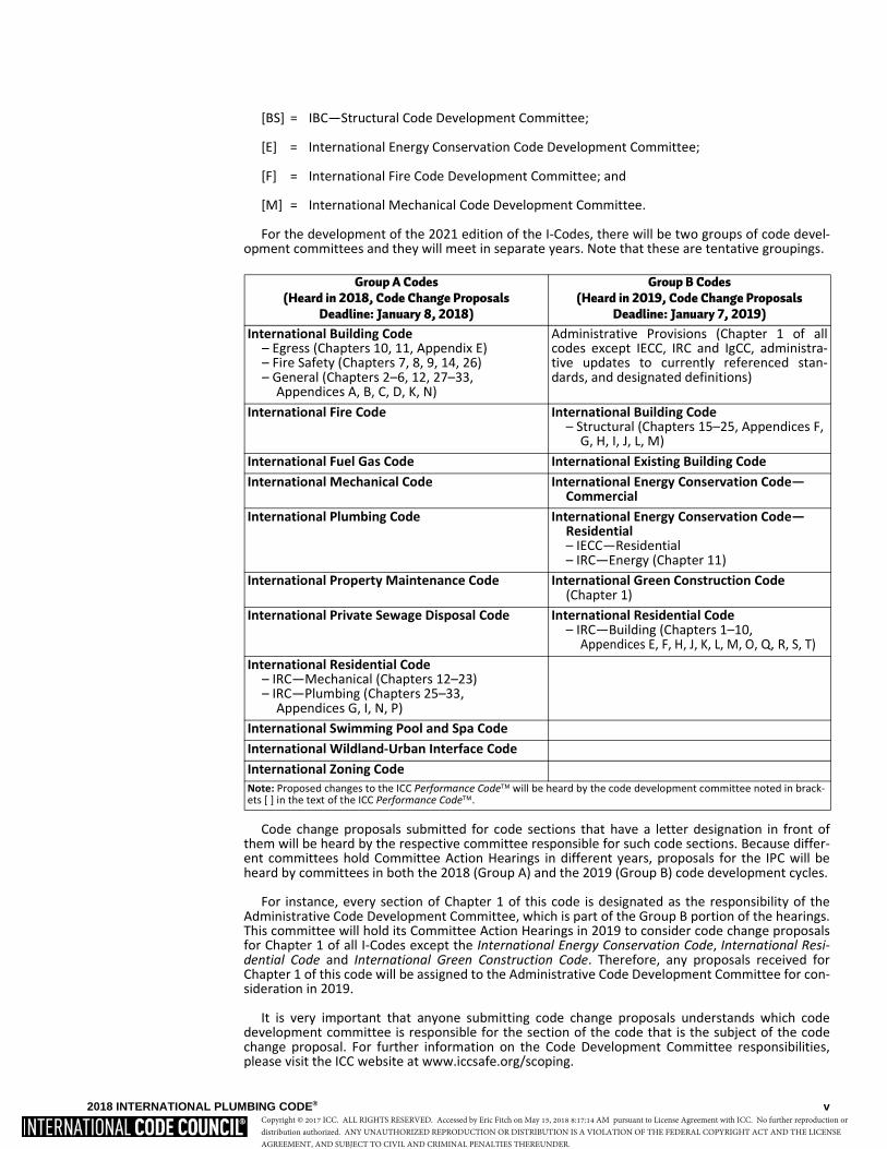
For the development of the 2021 edition of the I-Codes, there will be two groups of code devel-opment committees and they will meet in separate years. Note that these are tentative groupings.
Code change proposals submitted for code sections that have a letter designation in front ofthem will be heard by the respective committee responsible for such code sections. Because differ-ent committees hold Committee Action Hearings in different years, proposals for the IPC will beheard by committees in both the 2018 (Group A) and the 2019 (Group B) code development cycles.
For instance, every section of Chapter 1 of this code is designated as the responsibility of theAdministrative Code Development Committee, which is part of the Group B portion of the hearings.This committee will hold its Committee Action Hearings in 2019 to consider code change proposalsfor Chapter 1 of all I-Codes except the International Energy Conservation Code, International Resi-dential Code and International Green Construction Code. Therefore, any proposals received forChapter 1 of this code will be assigned to the Administrative Code Development Committee for con-sideration in 2019.
It is very important that anyone submitting code change proposals understands which codedevelopment committee is responsible for the section of the code that is the subject of the codechange proposal. For further information on the Code Development Committee responsibilities,please visit the ICC website at www.iccsafe.org/scoping.
Group A Codes(Heard in 2018, Code Change Proposals
Deadline: January 8, 2018)
Group B Codes(Heard in 2019, Code Change Proposals
Deadline: January 7, 2019)
International Building Code– Egress (Chapters 10, 11, Appendix E)– Fire Safety (Chapters 7, 8, 9, 14, 26)– General (Chapters 2–6, 12, 27–33,
Appendices A, B, C, D, K, N)
Administrative Provisions (Chapter 1 of allcodes except IECC, IRC and IgCC, administra-tive updates to currently referenced stan-dards, and designated definitions)
International Fire Code International Building Code– Structural (Chapters 15–25, Appendices F,
G, H, I, J, L, M)International Fuel Gas Code International Existing Building CodeInternational Mechanical Code International Energy Conservation Code—
CommercialInternational Plumbing Code International Energy Conservation Code—
Residential– IECC—Residential– IRC—Energy (Chapter 11)
International Property Maintenance Code International Green Construction Code(Chapter 1)
International Private Sewage Disposal Code International Residential Code– IRC—Building (Chapters 1–10,
Appendices E, F, H, J, K, L, M, O, Q, R, S, T)International Residential Code
– IRC—Mechanical (Chapters 12–23)– IRC—Plumbing (Chapters 25–33,
Appendices G, I, N, P)International Swimming Pool and Spa CodeInternational Wildland-Urban Interface CodeInternational Zoning CodeNote: Proposed changes to the ICC Performance Code will be heard by the code development committee noted in brack-ets [ ] in the text of the ICC Performance Code.
Copyright © 2017 ICC. ALL RIGHTS RESERVED. Accessed by Eric Fitch on May 15, 2018 8:17:14 AM pursuant to License Agreement with ICC. No further reproduction ordistribution authorized. ANY UNAUTHORIZED REPRODUCTION OR DISTRIBUTION IS A VIOLATION OF THE FEDERAL COPYRIGHT ACT AND THE LICENSEAGREEMENT, AND SUBJECT TO CIVIL AND CRIMINAL PENALTIES THEREUNDER.
vi 2018 INTERNATIONAL PLUMBING CODE®
Marginal Markings
Solid vertical lines in the margins within the body of the code indicate a technical change from therequirements of the 2015 edition. Deletion indicators in the form of an arrow ( ) are provided inthe margin where an entire section, paragraph, exception or table has been deleted or an item in alist of items or a table has been deleted.
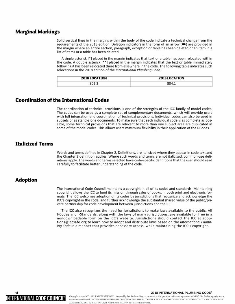
A single asterisk [*] placed in the margin indicates that text or a table has been relocated withinthe code. A double asterisk [**] placed in the margin indicates that the text or table immediatelyfollowing it has been relocated there from elsewhere in the code. The following table indicates suchrelocations in the 2018 edition of the International Plumbing Code.
Coordination of the International Codes
The coordination of technical provisions is one of the strengths of the ICC family of model codes.The codes can be used as a complete set of complementary documents, which will provide userswith full integration and coordination of technical provisions. Individual codes can also be used insubsets or as stand-alone documents. To make sure that each individual code is as complete as pos-sible, some technical provisions that are relevant to more than one subject area are duplicated insome of the model codes. This allows users maximum flexibility in their application of the I-Codes.
Italicized Terms
Words and terms defined in Chapter 2, Definitions, are italicized where they appear in code text andthe Chapter 2 definition applies. Where such words and terms are not italicized, common-use defi-nitions apply. The words and terms selected have code-specific definitions that the user should readcarefully to facilitate better understanding of the code.
Adoption
The International Code Council maintains a copyright in all of its codes and standards. Maintainingcopyright allows the ICC to fund its mission through sales of books, in both print and electronic for-mats. The ICC welcomes adoption of its codes by jurisdictions that recognize and acknowledge theICC’s copyright in the code, and further acknowledge the substantial shared value of the public/pri-vate partnership for code development between jurisdictions and the ICC.
The ICC also recognizes the need for jurisdictions to make laws available to the public. AllI-Codes and I-Standards, along with the laws of many jurisdictions, are available for free in anondownloadable form on the ICC’s website. Jurisdictions should contact the ICC at [email protected] to learn how to adopt and distribute laws based on the International Plumb-ing Code in a manner that provides necessary access, while maintaining the ICC’s copyright.
2018 LOCATION 2015 LOCATION
802.2 804.1
�
Copyright © 2017 ICC. ALL RIGHTS RESERVED. Accessed by Eric Fitch on May 15, 2018 8:17:14 AM pursuant to License Agreement with ICC. No further reproduction ordistribution authorized. ANY UNAUTHORIZED REPRODUCTION OR DISTRIBUTION IS A VIOLATION OF THE FEDERAL COPYRIGHT ACT AND THE LICENSEAGREEMENT, AND SUBJECT TO CIVIL AND CRIMINAL PENALTIES THEREUNDER.
2018 INTERNATIONAL PLUMBING CODE® vii
To facilitate adoption, several sections of this code contain blanks for fill-in informationthat needs to be supplied by the adopting jurisdiction as part of the adoption legislation. Forthis code, please see:
Section 101.1. Insert: [NAME OF JURISDICTION]
Section 106.6.2. Insert: [APPROPRIATE SCHEDULE]
Section 106.6.3. Insert: [PERCENTAGES IN TWO LOCATIONS]
Section 108.4. Insert: [OFFENSE, DOLLAR AMOUNT, NUMBER OF DAYS]
Section 108.5. Insert: [DOLLAR AMOUNT IN TWO LOCATIONS]
Section 305.4.1. Insert: [NUMBER OF INCHES IN TWO LOCATIONS]
Section 903.1. Insert: [NUMBER OF INCHES]
Copyright © 2017 ICC. ALL RIGHTS RESERVED. Accessed by Eric Fitch on May 15, 2018 8:17:14 AM pursuant to License Agreement with ICC. No further reproduction ordistribution authorized. ANY UNAUTHORIZED REPRODUCTION OR DISTRIBUTION IS A VIOLATION OF THE FEDERAL COPYRIGHT ACT AND THE LICENSEAGREEMENT, AND SUBJECT TO CIVIL AND CRIMINAL PENALTIES THEREUNDER.

viii 2018 INTERNATIONAL PLUMBING CODE®
Copyright © 2017 ICC. ALL RIGHTS RESERVED. Accessed by Eric Fitch on May 15, 2018 8:17:14 AM pursuant to License Agreement with ICC. No further reproduction ordistribution authorized. ANY UNAUTHORIZED REPRODUCTION OR DISTRIBUTION IS A VIOLATION OF THE FEDERAL COPYRIGHT ACT AND THE LICENSEAGREEMENT, AND SUBJECT TO CIVIL AND CRIMINAL PENALTIES THEREUNDER.

2018 INTERNATIONAL PLUMBING CODE® ix
EFFECTIVE USE OF THE INTERNATIONAL PLUMBING CODE
The International Plumbing Code (IPC) is a model code that regulates the design and installation ofplumbing systems including the plumbing fixtures in all types of buildings except for detached one-and two-family dwellings and townhouses that are not more than three stories above grade inheight. The regulations for plumbing systems in one- and two-family dwellings and townhouses arecovered by Chapters 25 through 33 of the International Residential Code (IRC). The IPC addressesgeneral plumbing regulations, fixture requirements, water heater installations and systems forwater distribution, sanitary drainage, special wastes, venting, storm drainage and medical gases.The IPC does not address fuel gas piping systems as those systems are covered by the InternationalFuel Gas Code (IFGC). The IPC also does not regulate swimming pool piping systems, process pipingsystems, or utility-owned piping and systems. The purpose of the IPC is to the establish the mini-mum acceptable level of safety to protect life and property from the potential dangers associatedwith supplying potable water to plumbing fixtures and outlets and the conveyance of bacteria-ladenwastewater from fixtures.
The IPC is primarily a specification-oriented (prescriptive) code with some performance-orientedtext. For example, Section 405.1 is a performance statement but Chapter 6 contains the prescriptiverequirements that will cause Section 405.1 to be satisfied.
Where a building contains plumbing fixtures, those fixtures requiring water must be providedwith an adequate supply of water for proper operation. The number of required plumbing fixturesfor a building is specified by this code and is based upon the anticipated maximum number of occu-pants for the building and the type of building occupancy. This code provides prescriptive criteriafor sizing piping systems connected to those fixtures. Through the use of code-approved materialsand the installation requirements specified in this code, plumbing systems will perform theirintended function over the life of the building. In summary, the IPC sets forth the minimum require-ments for providing safe water to a building as well as a safe manner in which liquid-borne wastesare carried away from a building.
Arrangement and Format of the 2018 IPC
The format of the IPC allows each chapter to be devoted to a particular subject with the exceptionof Chapter 3 which contains general subject matters that are not extensive enough to warrant theirown independent chapter.
Chapters Subjects
1–2 Administration and Definitions 3 General Regulations 4 Fixtures, Faucets and Fixture Fittings 5 Water Heaters 6 Water Supply and Distribution 7 Sanitary Drainage 8 Indirect/Special Waste 9 Vents
10 Traps, Interceptors and Separators 11 Storm Drainage 12 Special Piping (Medical Gas) 13 Nonpotable Water Systems14 Subsurface Landscape Irrigation Systems15 Referenced Standards
Appendices A–E Appendices
Copyright © 2017 ICC. ALL RIGHTS RESERVED. Accessed by Eric Fitch on May 15, 2018 8:17:14 AM pursuant to License Agreement with ICC. No further reproduction ordistribution authorized. ANY UNAUTHORIZED REPRODUCTION OR DISTRIBUTION IS A VIOLATION OF THE FEDERAL COPYRIGHT ACT AND THE LICENSEAGREEMENT, AND SUBJECT TO CIVIL AND CRIMINAL PENALTIES THEREUNDER.
x 2018 INTERNATIONAL PLUMBING CODE®
The following is a chapter-by-chapter synopsis of the scope and intent of the provisions of theInternational Plumbing Code:
Chapter 1 Scope and Administration. This chapter contains provisions for the application,enforcement and administration of subsequent requirements of the code. In addition to establish-ing the scope of the code, Chapter 1 identifies which buildings and structures come under its pur-view. Chapter 1 is largely concerned with maintaining “due process of law” in enforcing therequirements contained in the body of this code. Only through careful observation of the adminis-trative provisions can the code official reasonably expect to demonstrate that “equal protectionunder the law” has been provided.
Chapter 2 Definitions. Chapter 2 is the repository of the definitions of terms used in the body ofthe code. Codes are technical documents and every word, term and punctuation mark can impactthe meaning of the code text and the intended results. The code often uses terms that have aunique meaning in the code and the code meaning can differ substantially from the ordinarilyunderstood meaning of the term as used outside of the code.
The terms defined in Chapter 2 are deemed to be of prime importance in establishing the mean-ing and intent of the code text that uses the terms. The user of the code should be familiar with andconsult this chapter because the definitions are essential to the correct interpretation of the codeand because the user may not be aware that a term is defined.
Where understanding of a term’s definition is especially key to or necessary for understanding ofa particular code provision, the term is shown in italics. This is true only for those terms that have ameaning that is unique to the code. In other words, the generally understood meaning of a term orphrase might not be sufficient or consistent with the meaning prescribed by the code; therefore, itis essential that the code-defined meaning be known.
Guidance regarding tense, gender and plurality of defined terms as well as guidance regardingterms not defined in this code is provided.
Chapter 3 General Regulations. The content of Chapter 3 is often referred to as “miscella-neous,” rather than general regulations. This is the only chapter in the code whose requirements donot interrelate. If a requirement cannot be located in another chapter, it should be located in thischapter. Chapter 3 contains safety requirements for the installation of plumbing and nonplumbingrequirements for all types of fixtures. This chapter also has requirements for the identification ofpipe, pipe fittings, traps, fixtures, materials and devices used in plumbing systems.
The safety requirements of this chapter provide protection for the building’s structural mem-bers, as well as prevent undue stress and strain on pipes. The building’s structural stability is pro-tected by the regulations for cutting and notching of structural members. Additional protection forthe building occupants includes requirements to maintain the plumbing in a safe and sanitary condi-tion, as well as privacy for those occupants.
Chapter 4 Fixtures, Faucets and Fixture Fittings. This chapter regulates the minimum num-ber of plumbing fixtures that must be provided for every type of building. This chapter also regu-lates the quality of fixtures and faucets by requiring those items to comply with nationallyrecognized standards. Because fixtures must be properly installed so that they are usable by theoccupants of the building, this chapter contains the requirements for the installation of fixtures.Because the requirements for the number of plumbing fixtures affects the design of a building,Chapter 29 of the International Building Code (IBC) includes, verbatim, many of the requirementslisted in Chapter 4 of this code.
Chapter 5 Water Heaters. Chapter 5 regulates the design, approval and installation of waterheaters and related safety devices. The intent is to minimize the hazards associated with the instal-lation and operation of water heaters. Although this code does not regulate the size of a waterheater, it does regulate all other aspects of the water heater installation such as temperature andpressure relief valves, safety drip pans, installation and connections. Where a water heater also sup-plies water for space heating, this chapter regulates the maximum water temperature supplied tothe water distribution system.
Copyright © 2017 ICC. ALL RIGHTS RESERVED. Accessed by Eric Fitch on May 15, 2018 8:17:14 AM pursuant to License Agreement with ICC. No further reproduction ordistribution authorized. ANY UNAUTHORIZED REPRODUCTION OR DISTRIBUTION IS A VIOLATION OF THE FEDERAL COPYRIGHT ACT AND THE LICENSEAGREEMENT, AND SUBJECT TO CIVIL AND CRIMINAL PENALTIES THEREUNDER.
2018 INTERNATIONAL PLUMBING CODE® xi
Chapter 6 Water Supply and Distribution. This chapter regulates the supply of potable waterfrom both public and individual sources to every fixture and outlet so that it remains potable anduncontaminated. Chapter 6 also regulates the design of the water distribution system, which willallow fixtures to function properly and also help prevent backflow conditions. The unique require-ments of the water supply for health care facilities are addressed separately. It is critical that thepotable water supply system remain free of actual or potential sanitary hazards by providing protec-tion against backflow.
Chapter 7 Sanitary Drainage. The purpose of Chapter 7 is to regulate the materials, design andinstallation of sanitary drainage piping systems as well as the connections made to the system. Theintent is to design and install sanitary drainage systems that will function reliably, that are neitherundersized nor oversized and that are constructed from materials, fittings and connections as pre-scribed herein. This chapter addresses the proper use of fittings for directing the flow into andwithin the sanitary drain piping system. Materials and provisions necessary for servicing the drain-age system are also included in this chapter.
Chapter 8 Indirect/Special Waste. This chapter regulates drainage installations that requirean indirect connection to the sanitary drainage system. Fixtures and plumbing appliances, such asthose associated with food preparation or handling, health care facilities and potable liquids, mustbe protected from contamination that can result from connection to the drainage system. An indi-rect connection prevents sewage from backing up into a fixture or appliance, thus providing protec-tion against potential health hazards. The chapter also regulates special wastes containinghazardous chemicals. Special waste must be treated to prevent any damage to the sanitary drainagepiping and to protect the sewage treatment processes.
Chapter 9 Vents. Chapter 9 covers the requirements for vents and venting. Knowing why ventingis required makes it easier to understand the intent of this chapter. Venting protects every trapagainst the loss of its seal. Provisions set forth in this chapter are geared toward limiting the pres-sure differentials in the drainage system to a maximum of 1 inch of water column (249 Pa) above orbelow atmospheric pressure (i.e., positive or negative pressures).
Chapter 10 Traps, Interceptors and Separators. This chapter contains design requirementsand installation limitations for traps. Prohibited types of traps are specifically identified. Where fix-tures do not frequently replenish the water in traps, a method is provided to ensure that the waterseal of the trap will be maintained. Requirements for the design and location of various types ofinterceptors and separators are provided. Specific venting requirements are given for separatorsand interceptors as those requirements are not addressed in Chapter 9.
Chapter 11 Storm Drainage. Chapter 11 regulates the removal of storm water typically associ-ated with rainfall. The proper installation of a storm drainage system reduces the possibility ofstructural collapse of a flat roof, prevents the leakage of water through the roof, prevents damageto the footings and foundation of the building and prevents flooding of the lower levels of the build-ing.
Chapter 12 Special Piping and Storage Systems. This chapter contains the requirements forthe design, installation, storage, handling and use of nonflammable medical gas systems, includinginhalation anesthetic and vacuum piping systems, bulk oxygen storage systems and oxygen-fuel gassystems used for welding and cutting operations. The intent of these requirements is to minimizethe potential fire and explosion hazards associated with the gases used in these systems.
Chapter 13 Nonpotable Water Systems. This chapter regulates the design and installation ofnonpotable water systems. The reduction of potable water use in buildings has led building design-ers in some jurisdictions to use nonpotable water for irrigation and flushing of water closets and uri-nals. This chapter provides the overall requirements for these systems.
Chapter 14 Subsurface Landscape Irrigation Systems. This chapter regulates the designand installation of subsurface landscape irrigation systems for the disposal of on-site nonpotablewater such as graywater. The reduction of potable water use in buildings has led building designersin some jurisdictions to use on-site nonpotable water for irrigation. This chapter provides the over-all requirements for these systems.
Copyright © 2017 ICC. ALL RIGHTS RESERVED. Accessed by Eric Fitch on May 15, 2018 8:17:14 AM pursuant to License Agreement with ICC. No further reproduction ordistribution authorized. ANY UNAUTHORIZED REPRODUCTION OR DISTRIBUTION IS A VIOLATION OF THE FEDERAL COPYRIGHT ACT AND THE LICENSEAGREEMENT, AND SUBJECT TO CIVIL AND CRIMINAL PENALTIES THEREUNDER.
xii 2018 INTERNATIONAL PLUMBING CODE®
Chapter 15 Referenced Standards. Chapter 15 contains a comprehensive list of all standardsthat are referenced in the code. The standards are part of the code to the extent of the reference tothe standard. Compliance with the referenced standard is necessary for compliance with this code.By providing specifically adopted standards, the construction and installation requirements neces-sary for compliance with the code can be readily determined. The basis for code compliance is,therefore, established and available on an equal basis to the code official, contractor, designer andowner.
Chapter 15 is organized in a manner that makes it easy to locate specific standards. It lists all ofthe referenced standards, alphabetically, by acronym of the promulgating agency of the standard.Each agency’s standards are then listed in either alphabetical or numeric order based upon the stan-dard identification. The list also contains the title of the standard; the edition (date) of the standardreferenced; any addenda included as part of the ICC adoption; and the section or sections of thiscode that reference the standard.
Appendix A Plumbing Permit Fee Schedule. Appendix A provides a format for a fee schedule.
Appendix B Rates of Rainfall for Various Cities. Appendix B provides specific rainfall ratesfor major cities in the United States.
Appendix C Structural Safety. Appendix C is provided so that the user does not have to refer toanother code book for limitations for cutting, notching and boring of sawn lumber and cold-formedsteel framing.
Appendix D Degree Day and Design Temperatures. This appendix provides valuable tem-perature information for designers and installers of plumbing systems in areas where freezing tem-peratures might exist.
Appendix E Sizing of Water Piping System. Appendix E provides two recognized methods forsizing the water service and water distribution piping for any structure. The method under SectionE103 provides friction loss diagrams which require the user to “plot” points and read values fromthe diagrams in order to perform the required calculations and necessary checks. This method is themost accurate of the two presented in this appendix. The method under Section E201 is known tobe conservative; however, very few calculations are necessary in order to determine a pipe size thatsatisfies the flow requirements of any application.
Copyright © 2017 ICC. ALL RIGHTS RESERVED. Accessed by Eric Fitch on May 15, 2018 8:17:14 AM pursuant to License Agreement with ICC. No further reproduction ordistribution authorized. ANY UNAUTHORIZED REPRODUCTION OR DISTRIBUTION IS A VIOLATION OF THE FEDERAL COPYRIGHT ACT AND THE LICENSEAGREEMENT, AND SUBJECT TO CIVIL AND CRIMINAL PENALTIES THEREUNDER.

2018 INTERNATIONAL PLUMBING CODE® xiii
TABLE OF CONTENTS
CHAPTER 1 SCOPE AND ADMINISTRATION . . . . 1
PART 1—SCOPE AND APPLICATION. . . . . . . . . . . . . 1
Section
101 General . . . . . . . . . . . . . . . . . . . . . . . . . . . . . . . . . . . . 1
102 Applicability. . . . . . . . . . . . . . . . . . . . . . . . . . . . . . . . 1
PART 2—ADMINISTRATION AND ENFORCEMENT . . . . . . . . . . . . . . . . . . 2
Section
103 Department of Plumbing Inspection. . . . . . . . . . . . . . 2
104 Duties and Powers of the Code Official . . . . . . . . . . . 2
105 Approval . . . . . . . . . . . . . . . . . . . . . . . . . . . . . . . . . . . 3
106 Permits . . . . . . . . . . . . . . . . . . . . . . . . . . . . . . . . . . . . 3
107 Inspections and Testing . . . . . . . . . . . . . . . . . . . . . . . 5
108 Violations . . . . . . . . . . . . . . . . . . . . . . . . . . . . . . . . . . 7
109 Means of Appeal . . . . . . . . . . . . . . . . . . . . . . . . . . . . 8
110 Temporary Equipment, Systems and Uses. . . . . . . . . 8
CHAPTER 2 DEFINITIONS . . . . . . . . . . . . . . . . . . . . . 9
Section
201 General . . . . . . . . . . . . . . . . . . . . . . . . . . . . . . . . . . . . 9
202 General Definitions . . . . . . . . . . . . . . . . . . . . . . . . . . 9
CHAPTER 3 GENERAL REGULATIONS . . . . . . . . 17
Section
301 General . . . . . . . . . . . . . . . . . . . . . . . . . . . . . . . . . . . 17
302 Exclusion of Materials Detrimentalto the Sewer System . . . . . . . . . . . . . . . . . . . . . . . 17
303 Materials . . . . . . . . . . . . . . . . . . . . . . . . . . . . . . . . . . 17
304 Rodentproofing. . . . . . . . . . . . . . . . . . . . . . . . . . . . . 18
305 Protection of Pipes and PlumbingSystem Components . . . . . . . . . . . . . . . . . . . . . . . 18
306 Trenching, Excavation and Backfill . . . . . . . . . . . . . 18
307 Structural Safety . . . . . . . . . . . . . . . . . . . . . . . . . . . . 19
308 Piping Support . . . . . . . . . . . . . . . . . . . . . . . . . . . . . 19
309 Flood Hazard Resistance . . . . . . . . . . . . . . . . . . . . . 20
310 Washroom and Toilet Room Requirements . . . . . . . 20
311 Toilet Facilities for Workers . . . . . . . . . . . . . . . . . . 21
312 Tests and Inspections . . . . . . . . . . . . . . . . . . . . . . . . 21
313 Equipment Efficiencies . . . . . . . . . . . . . . . . . . . . . . 22
314 Condensate Disposal . . . . . . . . . . . . . . . . . . . . . . . . 22
315 Penetrations . . . . . . . . . . . . . . . . . . . . . . . . . . . . . . . 23
316 Alternative Engineered Design . . . . . . . . . . . . . . . . 23
CHAPTER 4 FIXTURES, FAUCETS AND FIXTURE FITTINGS . . . . . . . . . 25
Section
401 General. . . . . . . . . . . . . . . . . . . . . . . . . . . . . . . . . . . 25
402 Fixture Materials . . . . . . . . . . . . . . . . . . . . . . . . . . . 25
403 Minimum Plumbing Facilities . . . . . . . . . . . . . . . . . 25
404 Accessible Plumbing Facilities . . . . . . . . . . . . . . . . 29
405 Installation of Fixtures . . . . . . . . . . . . . . . . . . . . . . . 29
406 Automatic Clothes Washers. . . . . . . . . . . . . . . . . . . 30
407 Bathtubs . . . . . . . . . . . . . . . . . . . . . . . . . . . . . . . . . . 30
408 Bidets . . . . . . . . . . . . . . . . . . . . . . . . . . . . . . . . . . . . 30
409 Dishwashing Machines . . . . . . . . . . . . . . . . . . . . . . 31
410 Drinking Fountains . . . . . . . . . . . . . . . . . . . . . . . . . 31
411 Emergency Showers and Eyewash Stations . . . . . . 31
412 Faucets and other Fixture Fittings . . . . . . . . . . . . . . 31
413 Floor and Trench Drains . . . . . . . . . . . . . . . . . . . . . 32
414 Floor Sinks . . . . . . . . . . . . . . . . . . . . . . . . . . . . . . . . 32
415 Flushing Devices for Water Closets and Urinals. . . 32
416 Food Waste Disposer Units . . . . . . . . . . . . . . . . . . . 33
417 Garbage Can Washers . . . . . . . . . . . . . . . . . . . . . . . 33
418 Laundry Trays . . . . . . . . . . . . . . . . . . . . . . . . . . . . . 33
419 Lavatories. . . . . . . . . . . . . . . . . . . . . . . . . . . . . . . . . 33
420 Manual Food and Beverage Dispensing Equipment. . . . . . . . . . . . . . . . . . . . . 33
421 Showers . . . . . . . . . . . . . . . . . . . . . . . . . . . . . . . . . . 33
422 Sinks. . . . . . . . . . . . . . . . . . . . . . . . . . . . . . . . . . . . . 34
423 Specialty Plumbing Fixtures . . . . . . . . . . . . . . . . . . 35
424 Urinals . . . . . . . . . . . . . . . . . . . . . . . . . . . . . . . . . . . 35
425 Water Closets . . . . . . . . . . . . . . . . . . . . . . . . . . . . . 35
426 Whirlpool Bathtubs . . . . . . . . . . . . . . . . . . . . . . . . . 35
CHAPTER 5 WATER HEATERS. . . . . . . . . . . . . . . . 37
Section
501 General. . . . . . . . . . . . . . . . . . . . . . . . . . . . . . . . . . . 37
502 Installation . . . . . . . . . . . . . . . . . . . . . . . . . . . . . . . . 37
503 Connections . . . . . . . . . . . . . . . . . . . . . . . . . . . . . . . 38
504 Safety Devices . . . . . . . . . . . . . . . . . . . . . . . . . . . . . 38
505 Insulation . . . . . . . . . . . . . . . . . . . . . . . . . . . . . . . . . 39
Copyright © 2017 ICC. ALL RIGHTS RESERVED. Accessed by Eric Fitch on May 15, 2018 8:17:14 AM pursuant to License Agreement with ICC. No further reproduction ordistribution authorized. ANY UNAUTHORIZED REPRODUCTION OR DISTRIBUTION IS A VIOLATION OF THE FEDERAL COPYRIGHT ACT AND THE LICENSEAGREEMENT, AND SUBJECT TO CIVIL AND CRIMINAL PENALTIES THEREUNDER.
TABLE OF CONTENTS
xiv 2018 INTERNATIONAL PLUMBING CODE®
CHAPTER 6 WATER SUPPLY AND DISTRIBUTION . . . . . . . . . . . . . . 41
Section
601 General . . . . . . . . . . . . . . . . . . . . . . . . . . . . . . . . . . . 41
602 Water Required. . . . . . . . . . . . . . . . . . . . . . . . . . . . . 41
603 Water Service . . . . . . . . . . . . . . . . . . . . . . . . . . . . . . 41
604 Design of Building Water Distribution System . . . . . . . . . . . . . . . . . . . . . . . 42
605 Materials, Joints and Connections . . . . . . . . . . . . . . 44
606 Installation of the Building WaterDistribution System . . . . . . . . . . . . . . . . . . . . . . . 49
607 Hot Water Supply System . . . . . . . . . . . . . . . . . . . . 50
608 Protection of Potable Water Supply . . . . . . . . . . . . . 51
609 Health Care Plumbing . . . . . . . . . . . . . . . . . . . . . . . 57
610 Disinfection of Potable Water System . . . . . . . . . . . 57
611 Drinking Water Treatment Units . . . . . . . . . . . . . . . 58
612 Solar Systems . . . . . . . . . . . . . . . . . . . . . . . . . . . . . . 58
613 Temperature Control Devices and Valves . . . . . . . . 58
CHAPTER 7 SANITARY DRAINAGE. . . . . . . . . . . . 59
Section
701 General . . . . . . . . . . . . . . . . . . . . . . . . . . . . . . . . . . . 59
702 Materials. . . . . . . . . . . . . . . . . . . . . . . . . . . . . . . . . . 59
703 Building Sewer . . . . . . . . . . . . . . . . . . . . . . . . . . . . . 61
704 Drainage Piping Installation. . . . . . . . . . . . . . . . . . . 61
705 Joints. . . . . . . . . . . . . . . . . . . . . . . . . . . . . . . . . . . . . 62
706 Connections Between Drainage Piping and Fittings. . . . . . . . . . . . . . . . . . . . . . . . 64
707 Prohibited Joints and Connections . . . . . . . . . . . . . . 65
708 Cleanouts . . . . . . . . . . . . . . . . . . . . . . . . . . . . . . . . . 65
709 Fixture Units. . . . . . . . . . . . . . . . . . . . . . . . . . . . . . . 66
710 Drainage System Sizing . . . . . . . . . . . . . . . . . . . . . . 66
711 Offsets in Drainage Piping in Buildingsof Five Stories or More . . . . . . . . . . . . . . . . . . . . 68
712 Sumps and Ejectors . . . . . . . . . . . . . . . . . . . . . . . . . 68
713 Computerized Drainage Design . . . . . . . . . . . . . . . . 69
714 Backwater Valves. . . . . . . . . . . . . . . . . . . . . . . . . . . 70
715 Vacuum Drainage Systems . . . . . . . . . . . . . . . . . . . 70
716 Replacement of Underground Building Sewers and Building Drains by Pipe-Bursting
Methods . . . . . . . . . . . . . . . . . . . . . . . . . . . . . . . . 70
CHAPTER 8 INDIRECT/SPECIAL WASTE. . . . . . . 71
Section
801 General . . . . . . . . . . . . . . . . . . . . . . . . . . . . . . . . . . . 71
802 Indirect Wastes . . . . . . . . . . . . . . . . . . . . . . . . . . . . . 71
803 Special Wastes . . . . . . . . . . . . . . . . . . . . . . . . . . . . . 72
CHAPTER 9 VENTS. . . . . . . . . . . . . . . . . . . . . . . . . . . 73
Section
901 General. . . . . . . . . . . . . . . . . . . . . . . . . . . . . . . . . . . 73
902 Materials . . . . . . . . . . . . . . . . . . . . . . . . . . . . . . . . . 73
903 Vent Terminals. . . . . . . . . . . . . . . . . . . . . . . . . . . . . 73
904 Outdoor Vent Extensions. . . . . . . . . . . . . . . . . . . . . 73
905 Vent Connections and Grades . . . . . . . . . . . . . . . . . 74
906 Vent Pipe Sizing . . . . . . . . . . . . . . . . . . . . . . . . . . . 74
907 Vents for Stack Offsets . . . . . . . . . . . . . . . . . . . . . . 76
908 Relief Vents—Stacks of More Than 10 Branch Intervals . . . . . . . . . . . . . . . . . . . . . . . 76
909 Fixture Vents . . . . . . . . . . . . . . . . . . . . . . . . . . . . . . 76
910 Individual Vent . . . . . . . . . . . . . . . . . . . . . . . . . . . . 76
911 Common Vent . . . . . . . . . . . . . . . . . . . . . . . . . . . . . 77
912 Wet Venting . . . . . . . . . . . . . . . . . . . . . . . . . . . . . . . 77
913 Waste Stack Vent. . . . . . . . . . . . . . . . . . . . . . . . . . . 77
914 Circuit Venting. . . . . . . . . . . . . . . . . . . . . . . . . . . . . 78
915 Combination Waste and Vent System . . . . . . . . . . . 78
916 Island Fixture Venting . . . . . . . . . . . . . . . . . . . . . . . 79
917 Single-Stack Vent System . . . . . . . . . . . . . . . . . . . . 79
918 Air Admittance Valves . . . . . . . . . . . . . . . . . . . . . . 80
919 Engineered Vent Systems . . . . . . . . . . . . . . . . . . . . 80
920 Computerized Vent Design . . . . . . . . . . . . . . . . . . . 81
CHAPTER 10 TRAPS, INTERCEPTORS AND SEPARATORS . . . . . . . . . . . . . . 83
Section
1001 General . . . . . . . . . . . . . . . . . . . . . . . . . . . . . . . . . . 83
1002 Trap Requirements . . . . . . . . . . . . . . . . . . . . . . . . . 83
1003 Interceptors and Separators. . . . . . . . . . . . . . . . . . . 84
1004 Materials, Joints and Connections . . . . . . . . . . . . . 86
CHAPTER 11 STORM DRAINAGE. . . . . . . . . . . . . . 87
Section
1101 General . . . . . . . . . . . . . . . . . . . . . . . . . . . . . . . . . . 87
1102 Materials . . . . . . . . . . . . . . . . . . . . . . . . . . . . . . . . . 87
1103 Traps . . . . . . . . . . . . . . . . . . . . . . . . . . . . . . . . . . . . 88
1104 Conductors and Connections . . . . . . . . . . . . . . . . . 88
1105 Roof Drains. . . . . . . . . . . . . . . . . . . . . . . . . . . . . . . 88
1106 Size of Conductors, Leaders and Storm Drains . . . . . . . . . . . . . . . . . . . . . . . . 88
1107 Siphonic Roof Drainage Systems . . . . . . . . . . . . . . 94
1108 Secondary (Emergency) Roof Drains . . . . . . . . . . . 94
1109 Combined Sanitary and Storm Public Sewer . . . . . 95
1110 Controlled Flow Roof Drain Systems. . . . . . . . . . . 95
Copyright © 2017 ICC. ALL RIGHTS RESERVED. Accessed by Eric Fitch on May 15, 2018 8:17:14 AM pursuant to License Agreement with ICC. No further reproduction ordistribution authorized. ANY UNAUTHORIZED REPRODUCTION OR DISTRIBUTION IS A VIOLATION OF THE FEDERAL COPYRIGHT ACT AND THE LICENSEAGREEMENT, AND SUBJECT TO CIVIL AND CRIMINAL PENALTIES THEREUNDER.
TABLE OF CONTENTS
2018 INTERNATIONAL PLUMBING CODE® xv
1111 Subsoil Drains . . . . . . . . . . . . . . . . . . . . . . . . . . . . . 95
1112 Building Subdrains . . . . . . . . . . . . . . . . . . . . . . . . . 96
1113 Sumps and Pumping Systems . . . . . . . . . . . . . . . . . 96
CHAPTER 12 SPECIAL PIPING ANDSTORAGE SYSTEMS . . . . . . . . . . . . . 97
Section
1201 General . . . . . . . . . . . . . . . . . . . . . . . . . . . . . . . . . . 97
1202 Medical Gases . . . . . . . . . . . . . . . . . . . . . . . . . . . . . 97
1203 Oxygen Systems . . . . . . . . . . . . . . . . . . . . . . . . . . . 97
CHAPTER 13 NONPOTABLE WATER SYSTEMS . . . . . . . . . . . . . . . 99
Section
1301 General . . . . . . . . . . . . . . . . . . . . . . . . . . . . . . . . . . 99
1302 On-site Nonpotable Water Reuse Systems . . . . . . 101
1303 Nonpotable Rainwater Collection and Distribution Systems . . . . . . . . . . . . . . . . . . . . . 103
1304 Reclaimed Water Systems. . . . . . . . . . . . . . . . . . . 105
CHAPTER 14 SUBSURFACE LANDSCAPEIRRIGATION SYSTEMS . . . . . . . . . 107
Section
1401 General . . . . . . . . . . . . . . . . . . . . . . . . . . . . . . . . . 107
1402 System Design and Sizing. . . . . . . . . . . . . . . . . . . 107
1403 Installation . . . . . . . . . . . . . . . . . . . . . . . . . . . . . . . 109
CHAPTER 15 REFERENCED STANDARDS . . . . . 111
APPENDIX A PLUMBING PERMIT FEE SCHEDULE . . . . . . . . . . . . . . . . 127
Permit Issuance . . . . . . . . . . . . . . . . . . . . . . . . . . . . . . . . . 127
Unit Fee Schedule . . . . . . . . . . . . . . . . . . . . . . . . . . . . . . . 127
Other Inspections and Fees . . . . . . . . . . . . . . . . . . . . . . . . 127
APPENDIX B RATES OF RAINFALL FOR VARIOUS CITIES . . . . . . . . . . 129
APPENDIX C STRUCTURAL SAFETY . . . . . . . . . 131
Section
C101 Cutting, Notching and Boring inWood Members . . . . . . . . . . . . . . . . . . . . . . . . . 131
APPENDIX D DEGREE DAY AND DESIGN TEMPERATURES . . . . . . . 133
APPENDIX E SIZING OF WATER PIPING SYSTEM. . . . . . . . . . . . . . . . 139
Section
E101 General . . . . . . . . . . . . . . . . . . . . . . . . . . . . . . . . . 139
E102 Information Required . . . . . . . . . . . . . . . . . . . . . . 139
E103 Selection of Pipe Size . . . . . . . . . . . . . . . . . . . . . . 139
E201 Selection of Pipe Size . . . . . . . . . . . . . . . . . . . . . . 156
E202 Determination of Pipe Volumes . . . . . . . . . . . . . . 156
INDEX . . . . . . . . . . . . . . . . . . . . . . . . . . . . . . . . . . . . . . . 161
Copyright © 2017 ICC. ALL RIGHTS RESERVED. Accessed by Eric Fitch on May 15, 2018 8:17:14 AM pursuant to License Agreement with ICC. No further reproduction ordistribution authorized. ANY UNAUTHORIZED REPRODUCTION OR DISTRIBUTION IS A VIOLATION OF THE FEDERAL COPYRIGHT ACT AND THE LICENSEAGREEMENT, AND SUBJECT TO CIVIL AND CRIMINAL PENALTIES THEREUNDER.

xvi 2018 INTERNATIONAL PLUMBING CODE®
Copyright © 2017 ICC. ALL RIGHTS RESERVED. Accessed by Eric Fitch on May 15, 2018 8:17:14 AM pursuant to License Agreement with ICC. No further reproduction ordistribution authorized. ANY UNAUTHORIZED REPRODUCTION OR DISTRIBUTION IS A VIOLATION OF THE FEDERAL COPYRIGHT ACT AND THE LICENSEAGREEMENT, AND SUBJECT TO CIVIL AND CRIMINAL PENALTIES THEREUNDER.
2018 INTERNATIONAL PLUMBING CODE® 1
CHAPTER 1
SCOPE AND ADMINISTRATION
User note:
About this chapter: Chapter 1 establishes the limits of applicability of this code and describes how the code is to be applied and enforced.Chapter 1 is in two parts: Part 1—Scope and Application (Sections 101–102) and Part 2—Administration and Enforcement (Sections 103–110). Section 101 identifies which buildings and structures come under its purview and references other I-Codes as applicable. Standards andcodes are scoped to the extent referenced (see Section 102.8).
This code is intended to be adopted as a legally enforceable document and it cannot be effective without adequate provisions for its adminis-tration and enforcement. The provisions of Chapter 1 establish the authority and duties of the code official appointed by the authority havingjurisdiction and also establish the rights and privileges of the design professional, contractor and property owner.
PART 1—SCOPE AND APPLICATION
SECTION 101GENERAL
[A] 101.1 Title. These regulations shall be known as thePlumbing Code of [NAME OF JURISDICTION] hereinafterreferred to as “this code.”
[A] 101.2 Scope. The provisions of this code shall apply tothe erection, installation, alteration, repairs, relocation,replacement, addition to, use or maintenance of plumbingsystems within this jurisdiction. This code shall regulate non-flammable medical gas, inhalation anesthetic, vacuum piping,nonmedical oxygen systems and sanitary and condensate vac-uum collection systems. The installation of fuel gas distribu-tion piping and equipment, fuel-gas-fired water heaters andwater heater venting systems shall be regulated by the Inter-national Fuel Gas Code. Provisions in the appendices shallnot apply unless specifically adopted.
Exception: Detached one- and two-family dwellings andmultiple single-family dwellings (townhouses) not morethan three stories high with separate means of egress andtheir accessory structures shall comply with the Interna-tional Residential Code.
[A] 101.3 Intent. The purpose of this code is to establishminimum standards to provide a reasonable level of safety,health, property protection and public welfare by regulatingand controlling the design, construction, installation, qualityof materials, location, operation and maintenance or use ofplumbing equipment and systems.
[A] 101.4 Severability. If any section, subsection, sentence,clause or phrase of this code is for any reason held to beunconstitutional, such decision shall not affect the validity ofthe remaining portions of this code.
SECTION 102 APPLICABILITY
[A] 102.1 General. Where there is a conflict between a gen-eral requirement and a specific requirement, the specificrequirement shall govern. Where, in any specific case, differ-ent sections of this code specify different materials, methods
of construction or other requirements, the most restrictiveshall govern.
[A] 102.2 Existing installations. Plumbing systems lawfullyin existence at the time of the adoption of this code shall bepermitted to have their use and maintenance continued if theuse, maintenance or repair is in accordance with the originaldesign and hazard to life, health or property is not created bysuch plumbing system.
[A] 102.2.1 Existing buildings. Additions, alterations,renovations or repairs related to building or structuralissues shall be regulated by the International ExistingBuilding Code.
[A] 102.3 Maintenance. Plumbing systems, materials andappurtenances, both existing and new, and parts thereof, shallbe maintained in proper operating condition in accordancewith the original design in a safe and sanitary condition.Devices or safeguards required by this code shall be main-tained in compliance with the edition of the code under whichthey were installed.
The owner or the owner’s authorized agent shall beresponsible for maintenance of plumbing systems. To deter-mine compliance with this provision, the code official shallhave the authority to require any plumbing system to be rein-spected.
[A] 102.4 Additions, alterations or repairs. Additions,alterations, renovations or repairs to any plumbing systemshall conform to that required for a new plumbing systemwithout requiring the existing plumbing system to complywith all the requirements of this code. Additions, alterationsor repairs shall not cause an existing system to becomeunsafe, insanitary or overloaded.
Minor additions, alterations, renovations and repairs toexisting plumbing systems shall meet the provisions for newconstruction, unless such work is done in the same mannerand arrangement as was in the existing system, is not hazard-ous and is approved.
[A] 102.5 Change in occupancy. It shall be unlawful tomake any change in the occupancy of any structure that willsubject the structure to any special provision of this codeapplicable to the new occupancy without approval of the codeofficial. The code official shall certify that such structure
Copyright © 2017 ICC. ALL RIGHTS RESERVED. Accessed by Eric Fitch on May 15, 2018 8:17:14 AM pursuant to License Agreement with ICC. No further reproduction ordistribution authorized. ANY UNAUTHORIZED REPRODUCTION OR DISTRIBUTION IS A VIOLATION OF THE FEDERAL COPYRIGHT ACT AND THE LICENSEAGREEMENT, AND SUBJECT TO CIVIL AND CRIMINAL PENALTIES THEREUNDER.

SCOPE AND ADMINISTRATION
2 2018 INTERNATIONAL PLUMBING CODE®
meets the intent of the provisions of law governing buildingconstruction for the proposed new occupancy and that suchchange of occupancy does not result in any hazard to the pub-lic health, safety or welfare.
[A] 102.6 Historic buildings. The provisions of this coderelating to the construction, alteration, repair, enlargement,restoration, relocation or moving of buildings or structuresshall not be mandatory for existing buildings or structuresidentified and classified by the state or local jurisdiction ashistoric buildings where such buildings or structures arejudged by the code official to be safe and in the public inter-est of health, safety and welfare regarding any proposed con-struction, alteration, repair, enlargement, restoration,relocation or moving of buildings.
[A] 102.7 Moved buildings. Except as determined by Sec-tion 102.2, plumbing systems that are a part of buildings orstructures moved into or within the jurisdiction shall complywith the provisions of this code for new installations.
[A] 102.8 Referenced codes and standards. The codes andstandards referenced in this code shall be those that are listedin Chapter 15 and such codes and standards shall be consid-ered as part of the requirements of this code to the prescribedextent of each such reference and as further regulated in Sec-tions 102.8.1 and 102.8.2.
[A] 102.8.1 Conflicts. Where conflicts occur between pro-visions of this code and the referenced standards, the pro-visions of this code shall apply.
[A] 102.8.2 Provisions in referenced codes and stan-dards. Where the extent of the reference to a referencedcode or standard includes subject matter that is within thescope of this code, the provisions of this code, as applica-ble, shall take precedence over the provisions in the refer-enced code or standard.
[A] 102.9 Requirements not covered by code. Any require-ments necessary for the strength, stability or proper operationof an existing or proposed plumbing system, or for the publicsafety, health and general welfare, not specifically covered bythis code shall be determined by the code official.
[A] 102.10 Other laws. The provisions of this code shall notbe deemed to nullify any provisions of local, state or federallaw.
[A] 102.11 Application of references. Reference to chaptersection numbers, or to provisions not specifically identifiedby number, shall be construed to refer to such chapter, sectionor provision of this code.
PART 2—ADMINISTRATION AND ENFORCEMENT
SECTION 103 DEPARTMENT OF PLUMBING INSPECTION
[A] 103.1 General. The department of plumbing inspectionis hereby created and the executive official in charge thereofshall be known as the code official.
[A] 103.2 Appointment. The code official shall be appointedby the chief appointing authority of the jurisdiction.
[A] 103.3 Deputies. In accordance with the prescribed proce-dures of this jurisdiction and with the concurrence of theappointing authority, the code official shall have the authorityto appoint a deputy code official, other related technical offi-cers, inspectors and other employees. Such employees shallhave powers as delegated by the code official.
[A] 103.4 Liability. The code official, member of the boardof appeals or employee charged with the enforcement of thiscode, while acting for the jurisdiction in good faith and with-out malice in the discharge of the duties required by this codeor other pertinent law or ordinance, shall not thereby be ren-dered civilly or criminally liable personally, and is herebyrelieved from all personal liability for any damage accruingto persons or property as a result of any act or by reason of anact or omission in the discharge of official duties.
[A] 103.4.1 Legal defense. Any suit or criminal complaintinstituted against any officer or employee because of anact performed by that officer or employee in the lawfuldischarge of duties and under the provisions of this codeshall be defended by the legal representative of the juris-diction until the final termination of the proceedings. Thecode official or any subordinate shall not be liable forcosts in any action, suit or proceeding that is instituted inpursuance of the provisions of this code.
SECTION 104 DUTIES AND POWERS OF THE CODE OFFICIAL
[A] 104.1 General. The code official is hereby authorizedand directed to enforce the provisions of this code. The codeofficial shall have the authority to render interpretations ofthis code and to adopt policies and procedures in order toclarify the application of its provisions. Such interpretations,policies and procedures shall be in compliance with the intentand purpose of this code. Such policies and procedures shallnot have the effect of waiving requirements specifically pro-vided for in this code.
[A] 104.2 Applications and permits. The code official shallreceive applications, review construction documents andissue permits for the installation and alteration of plumbingsystems, inspect the premises for which such permits havebeen issued, and enforce compliance with the provisions ofthis code.
[A] 104.3 Inspections. The code official shall make all therequired inspections, or shall accept reports of inspection byapproved agencies or individuals. Reports of such inspectionsshall be in writing and be certified by a responsible officer ofsuch approved agency or by the responsible individual. Thecode official is authorized to engage such expert opinion asdeemed necessary to report on unusual technical issues thatarise, subject to the approval of the appointing authority.
[A] 104.4 Right of entry. Where it is necessary to make aninspection to enforce the provisions of this code, or where thecode official has reasonable cause to believe that there existsin any building or on any premises any conditions or viola-
Copyright © 2017 ICC. ALL RIGHTS RESERVED. Accessed by Eric Fitch on May 15, 2018 8:17:14 AM pursuant to License Agreement with ICC. No further reproduction ordistribution authorized. ANY UNAUTHORIZED REPRODUCTION OR DISTRIBUTION IS A VIOLATION OF THE FEDERAL COPYRIGHT ACT AND THE LICENSEAGREEMENT, AND SUBJECT TO CIVIL AND CRIMINAL PENALTIES THEREUNDER.
SCOPE AND ADMINISTRATION
2018 INTERNATIONAL PLUMBING CODE® 3
tions of this code that make the building or premises unsafe,insanitary, dangerous or hazardous, the code official shallhave the authority to enter the building or premises at all rea-sonable times to inspect or to perform the duties imposedupon the code official by this code. If such building or prem-ises is occupied, the code official shall present credentials tothe occupant and request entry. If such building or premises isunoccupied, the code official shall first make a reasonableeffort to locate the owner, the owner’s authorized agent orother person having charge or control of the building orpremises and request entry. If entry is refused, the code offi-cial shall have recourse to every remedy provided by law tosecure entry.
Where the code official shall have first obtained a properinspection warrant or other remedy provided by law to secureentry, the owner, owner’s authorized agent, occupant or per-son having charge, care or control of any building or premisesshall not fail or neglect, after proper request is made as hereinprovided, to promptly permit entry therein by the code offi-cial for the purpose of inspection and examination pursuant tothis code.
[A] 104.5 Identification. The code official shall carry properidentification when inspecting structures or premises in theperformance of duties under this code.
[A] 104.6 Notices and orders. The code official shall issueall necessary notices or orders to ensure compliance with thiscode.
[A] 104.7 Department records. The code official shall keepofficial records of applications received, permits and certifi-cates issued, fees collected, reports of inspections, andnotices and orders issued. Such records shall be retained inthe official records for the period required for the retention ofpublic records.
SECTION 105 APPROVAL
[A] 105.1 Modifications. Where there are practical difficul-ties involved in carrying out the provisions of this code, thecode official shall have the authority to grant modificationsfor individual cases, upon application of the owner orowner’s authorized agent, provided that the code official shallfirst find that special individual reason makes the strict letterof this code impractical and the modification conforms to theintent and purpose of this code and that such modificationdoes not lessen health, life and fire safety requirements. Thedetails of action granting modifications shall be recorded andentered in the files of the plumbing inspection department.
[A] 105.2 Alternative materials, design and methods ofconstruction and equipment. The provisions of this codeare not intended to prevent the installation of any material orto prohibit any design or method of construction not specifi-cally prescribed by this code, provided that any such alterna-tive has been approved. An alternative material or method ofconstruction shall be approved where the code official findsthat the proposed design is satisfactory and complies with theintent of the provisions of this code, and that the material,method or work offered is, for the purpose intended, not lessthan the equivalent of that prescribed in this code in quality,
strength, effectiveness, fire resistance, durability and safety.Where the alternative material, design or method of construc-tion is not approved, the code official shall respond in writ-ing, stating the reasons why the alternative was not approved.
[A] 105.2.1 Research reports. Supporting data, wherenecessary to assist in the approval of materials or assem-blies not specifically provided for in this code, shall con-sist of valid research reports from approved sources.
[A] 105.3 Required testing. Where there is insufficient evi-dence of compliance with the provisions of this code, or evi-dence that a material or method does not conform to therequirements of this code, or in order to substantiate claimsfor alternate materials or methods, the code official shall havethe authority to require tests as evidence of compliance to bemade at no expense to the jurisdiction.
[A] 105.3.1 Test methods. Test methods shall be as speci-fied in this code or by other recognized test standards. Inthe absence of recognized and accepted test methods, thecode official shall approve the testing procedures.
[A] 105.3.2 Testing agency. Tests shall be performed byan approved agency.
[A] 105.3.3 Test reports. Reports of tests shall be retainedby the code official for the period required for retention ofpublic records.
[A] 105.4 Approved materials and equipment. Materials,equipment and devices approved by the code official shall beconstructed and installed in accordance with such approval.
[A] 105.4.1 Material and equipment reuse. Materials,equipment and devices shall not be reused unless such ele-ments have been reconditioned, tested, placed in good andproper working condition and approved.
SECTION 106PERMITS
[A] 106.1 Where required. Any owner, owner’s authorizedagent or contractor who desires to construct, enlarge, alter,repair, move, demolish or change the occupancy of a buildingor structure, or to erect, install, enlarge, alter, repair, remove,convert or replace any plumbing system, the installation ofwhich is regulated by this code, or to cause any such work tobe performed, shall first make application to the code officialand obtain the required permit for the work.
[A] 106.1.1 Annual permit. Instead of an individual con-struction permit for each alteration to an already approvedsystem or equipment or appliance installation, the codeofficial is authorized to issue an annual permit upon appli-cation therefor to any person, firm or corporation regularlyemploying one or more qualified tradespersons in thebuilding, structure or on the premises owned or operatedby the applicant for the permit.
[A] 106.1.2 Annual permit records. The person to whoman annual permit is issued shall keep a detailed record ofalterations made under such annual permit. The code offi-cial shall have access to such records at all times or suchrecords shall be filed with the code official as designated.
Copyright © 2017 ICC. ALL RIGHTS RESERVED. Accessed by Eric Fitch on May 15, 2018 8:17:14 AM pursuant to License Agreement with ICC. No further reproduction ordistribution authorized. ANY UNAUTHORIZED REPRODUCTION OR DISTRIBUTION IS A VIOLATION OF THE FEDERAL COPYRIGHT ACT AND THE LICENSEAGREEMENT, AND SUBJECT TO CIVIL AND CRIMINAL PENALTIES THEREUNDER.
SCOPE AND ADMINISTRATION
4 2018 INTERNATIONAL PLUMBING CODE®
[A] 106.2 Exempt work. The following work shall beexempt from the requirement for a permit:
1. The stopping of leaks in drains, water, soil, waste orvent pipe provided, however, that if any concealed trap,drainpipe, water, soil, waste or vent pipe becomesdefective and it becomes necessary to remove andreplace the same with new material, such work shall beconsidered as new work and a permit shall be obtainedand inspection made as provided in this code.
2. The clearing of stoppages or the repairing of leaks inpipes, valves or fixtures, and the removal and reinstal-lation of water closets, provided that such repairs donot involve or require the replacement or rearrange-ment of valves, pipes or fixtures.
Exemption from the permit requirements of this code shallnot be deemed to grant authorization for any work to be donein violation of the provisions of this code or any other laws orordinances of this jurisdiction.
[A] 106.3 Application for permit. Each application for apermit, with the required fee, shall be filed with the code offi-cial on a form furnished for that purpose and shall contain ageneral description of the proposed work and its location. Theapplication shall be signed by the owner or owner’s autho-rized agent. The permit application shall indicate the pro-posed occupancy of all parts of the building and of thatportion of the site or lot, if any, not covered by the building orstructure and shall contain such other information required bythe code official.
[A] 106.3.1 Construction documents. Construction doc-uments, engineering calculations, diagrams and other suchdata shall be submitted in two or more sets with eachapplication for a permit. The code official shall requireconstruction documents, computations and specificationsto be prepared and designed by a registered design profes-sional where required by state law. Construction docu-ments shall be drawn to scale and shall be of sufficientclarity to indicate the location, nature and extent of thework proposed and show in detail that the work conformsto the provisions of this code. Construction documents forbuildings more than two stories in height shall indicatewhere penetrations will be made for pipes, fittings andcomponents and shall indicate the materials and methodsfor maintaining required structural safety, fire-resistancerating and fireblocking.
Exception: The code official shall have the authority towaive the submission of construction documents, cal-culations or other data if the nature of the work appliedfor is such that reviewing of construction documents isnot necessary to determine compliance with this code.
[A] 106.3.2 Preliminary inspection. Before a permit isissued, the code official shall be authorized to inspect andevaluate the systems, equipment, buildings, devices, prem-ises and spaces or areas to be used.
[A] 106.3.3 Time limitation of application. An applica-tion for a permit for any proposed work shall be deemed tohave been abandoned 180 days after the date of filing,unless such application has been pursued in good faith or apermit has been issued; except that the code official shall
have the authority to grant one or more extensions of timefor additional periods not exceeding 180 days each. Theextension shall be requested in writing and justifiablecause demonstrated.
[A] 106.4 By whom application is made. Application for apermit shall be made by the person or agent to install all orpart of any plumbing system. The applicant shall meet allqualifications established by statute, or by rules promulgatedby this code, or by ordinance or by resolution. The full nameand address of the applicant shall be stated in the application.
[A] 106.5 Permit issuance. The application, constructiondocuments and other data filed by an applicant for permitshall be reviewed by the code official. If the code officialfinds that the proposed work conforms to the requirements ofthis code and all laws and ordinances applicable thereto, andthat the fees specified in Section 106.6 have been paid, a per-mit shall be issued to the applicant.
[A] 106.5.1 Approved construction documents. Whenthe code official issues the permit where construction doc-uments are required, the construction documents shall beendorsed in writing and stamped “APPROVED.” Suchapproved construction documents shall not be changed,modified or altered without authorization from the codeofficial. Work shall be done in accordance with theapproved construction documents.
The code official shall have the authority to issue a per-mit for the construction of a part of a plumbing systembefore the entire construction documents for the wholesystem have been submitted or approved, provided thatadequate information and detailed statements have beenfiled complying with all pertinent requirements of thiscode. The holders of such permit shall proceed at theirown risk without assurance that the permit for the entireplumbing system will be granted.
[A] 106.5.2 Validity. The issuance of a permit or approvalof construction documents shall not be construed to be apermit for, or an approval of, any violation of any of theprovisions of this code or any other ordinance of the juris-diction. A permit presuming to give authority to violate orcancel the provisions of this code shall not be valid.
The issuance of a permit based on construction docu-ments and other data shall not prevent the code officialfrom thereafter requiring the correction of errors in saidconstruction documents and other data or from preventingbuilding operations being carried on thereunder where inviolation of this code or of other ordinances of this juris-diction.
[A] 106.5.3 Expiration. Every permit issued by the codeofficial under the provisions of this code shall expire bylimitation and become null and void if the work authorizedby such permit is not commenced within 180 days fromthe date of such permit, or if the work authorized by suchpermit is suspended or abandoned at any time after thework is commenced for a period of 180 days. Before suchwork can be recommenced, a new permit shall be firstobtained and the fee therefor shall be one-half the amountrequired for a new permit for such work, provided thatchanges have not been made and will not be made in the
Copyright © 2017 ICC. ALL RIGHTS RESERVED. Accessed by Eric Fitch on May 15, 2018 8:17:14 AM pursuant to License Agreement with ICC. No further reproduction ordistribution authorized. ANY UNAUTHORIZED REPRODUCTION OR DISTRIBUTION IS A VIOLATION OF THE FEDERAL COPYRIGHT ACT AND THE LICENSEAGREEMENT, AND SUBJECT TO CIVIL AND CRIMINAL PENALTIES THEREUNDER.
SCOPE AND ADMINISTRATION
2018 INTERNATIONAL PLUMBING CODE® 5
original construction documents for such work, and pro-vided further that such suspension or abandonment has notexceeded 1 year.
[A] 106.5.4 Extensions. Any permittee holding an unex-pired permit shall have the right to apply for an extensionof the time within which the permittee will commencework under that permit when work is unable to be com-menced within the time required by this section for goodand satisfactory reasons. The code official shall extend thetime for action by the permittee for a period not exceeding180 days if there is reasonable cause. A permit shall not beextended more than once. The fee for an extension shall beone-half the amount required for a new permit for suchwork.
[A] 106.5.5 Suspension or revocation of permit. Thecode official shall have the authority to suspend or revokea permit issued under the provisions of this code whereverthe permit is issued in error or on the basis of incorrect,inaccurate or incomplete information, or in violation ofany ordinance or regulation or any of the provisions of thiscode.
[A] 106.5.6 Retention of construction documents. Oneset of approved construction documents shall be retainedby the code official for a period of not less than 180 daysfrom date of completion of the permitted work, or asrequired by state or local laws.
One set of approved construction documents shall bereturned to the applicant, and said set shall be kept on thesite of the building or work at all times during which thework authorized thereby is in progress.
[A] 106.5.7 Previous approvals. This code shall notrequire changes in the construction documents, construc-tion or designated occupancy of a structure for which alawful permit has been heretofore issued or otherwise law-fully authorized, and the construction of which has beenpursued in good faith within 180 days after the effectivedate of this code and has not been abandoned.
[A] 106.5.8 Posting of permit. The permit or a copy shallbe kept on the site of the work until the completion of theproject.
[A] 106.6 Fees. A permit shall not be issued until the feesprescribed in Section 106.6.2 have been paid, and an amend-ment to a permit shall not be released until the additional fee,if any, due to an increase of the plumbing systems, has beenpaid.
[A] 106.6.1 Work commencing before permit issuance.Any person who commences any work on a plumbing sys-tem before obtaining the necessary permits shall be subjectto 100 percent of the usual permit fee in addition to therequired permit fees.
[A] 106.6.2 Fee schedule. The fees for all plumbing workshall be as indicated in the following schedule:
[JURISDICTION TO INSERT APPROPRIATE SCHEDULE]
[A] 106.6.3 Fee refunds. The code official shall authorizethe refunding of fees as follows:
1. The full amount of any fee paid hereunder that waserroneously paid or collected.
2. Not more than [SPECIFY PERCENTAGE] percent ofthe permit fee paid where work has been done undera permit issued in accordance with this code.
3. Not more than [SPECIFY PERCENTAGE] percent ofthe plan review fee paid where an application for apermit for which a plan review fee has been paid iswithdrawn or canceled before any plan review efforthas been expended.
The code official shall not authorize the refunding ofany fee paid except upon written application filed by theoriginal permittee not later than 180 days after the date offee payment.
SECTION 107 INSPECTIONS AND TESTING
[A] 107.1 General. The code official is authorized to conductsuch inspections as are deemed necessary to determine com-pliance with the provisions of this code. Construction or workfor which a permit is required shall be subject to inspectionby the code official, and such construction or work shallremain visible and able to be accessed for inspection pur-poses until approved. Approval as a result of an inspectionshall not be construed to be an approval of a violation of theprovisions of this code or of other ordinances of the jurisdic-tion. Inspections presuming to give authority to violate orcancel the provisions of this code or of other ordinances ofthe jurisdiction shall not be valid. It shall be the duty of thepermit applicant to cause the work to remain visible and ableto be accessed for inspection purposes. Neither the code offi-cial nor the jurisdiction shall be liable for expense entailed inthe removal or replacement of any material required to allowinspection.
[A] 107.2 Required inspections and testing. The code offi-cial, upon notification from the permit holder or the permitholder’s agent, shall make the following inspections and suchother inspections as necessary, and shall either release thatportion of the construction or shall notify the permit holder oran agent of any violations that must be corrected. The holderof the permit shall be responsible for the scheduling of suchinspections.
1. Underground inspection shall be made after trenches orditches are excavated and bedded, piping installed, andbefore any backfill is put in place.
2. Rough-in inspection shall be made after the roof, fram-ing, fireblocking, firestopping, draftstopping and brac-ing is in place and all sanitary, storm and waterdistribution piping is roughed-in, and prior to the instal-lation of wall or ceiling membranes.
3. Final inspection shall be made after the building iscomplete, all plumbing fixtures are in place and prop-erly connected, and the structure is ready for occu-pancy.
[A] 107.2.1 Other inspections. In addition to the inspec-tions specified in Section 107.2, the code official shall beauthorized to make or require other inspections of anyconstruction work to ascertain compliance with the provi-sions of this code and other laws that are enforced.
Copyright © 2017 ICC. ALL RIGHTS RESERVED. Accessed by Eric Fitch on May 15, 2018 8:17:14 AM pursuant to License Agreement with ICC. No further reproduction ordistribution authorized. ANY UNAUTHORIZED REPRODUCTION OR DISTRIBUTION IS A VIOLATION OF THE FEDERAL COPYRIGHT ACT AND THE LICENSEAGREEMENT, AND SUBJECT TO CIVIL AND CRIMINAL PENALTIES THEREUNDER.
SCOPE AND ADMINISTRATION
6 2018 INTERNATIONAL PLUMBING CODE®
[A] 107.2.2 Inspection requests. It shall be the duty of theholder of the permit or their duly authorized agent tonotify the code official when work is ready for inspection.It shall be the duty of the permit holder to provide accessto and means for inspections of such work that arerequired by this code.
[A] 107.2.3 Approval required. Work shall not be donebeyond the point indicated in each successive inspectionwithout first obtaining the approval of the code official.The code official, upon notification, shall make therequested inspections and shall either indicate the portionof the construction that is satisfactory as completed, ornotify the permit holder or his or her agent wherein thesame fails to comply with this code. Any portions that donot comply shall be corrected and such portion shall not becovered or concealed until authorized by the code official.
[A] 107.2.4 Approved agencies. The code official isauthorized to accept reports of approved inspection agen-cies, provided that such agencies satisfy the requirementsas to qualifications and reliability.
[A] 107.2.5 Evaluation and follow-up inspection ser-vices. Prior to the approval of a closed, prefabricatedplumbing system and the issuance of a plumbing permit,the code official shall require the submittal of an evalua-tion report on each prefabricated plumbing system indicat-ing the complete details of the plumbing system, includinga description of the system and its components, the basison which the plumbing system is being evaluated, testresults and similar information, and other data as neces-sary for the code official to determine conformance to thiscode.
[A] 107.2.5.1 Evaluation service. The code officialshall designate the evaluation service of an approvedagency as the evaluation agency, and review suchagency’s evaluation report for adequacy and confor-mance to this code.
[A] 107.2.5.2 Follow-up inspection. Except whereready access is provided to all plumbing systems, ser-vice equipment and accessories for complete inspectionat the site without disassembly or dismantling, the codeofficial shall conduct the frequency of in-plant inspec-tions necessary to ensure conformance to the approvedevaluation report or shall designate an independent,approved inspection agency to conduct such inspec-tions. The inspection agency shall furnish the code offi-cial with the follow-up inspection manual and a reportof inspections on request, and the plumbing systemshall have an identifying label permanently affixed tothe system indicating that factory inspections have beenperformed.
[A] 107.2.5.3 Test and inspection records. Requiredtest and inspection records shall be available to thecode official at all times during the fabrication of theplumbing system and the erection of the building, orsuch records as the code official designates shall befiled.
[A] 107.3 Special inspections. Special inspections of alter-native engineered design plumbing systems shall be con-ducted in accordance with Sections 107.3.1 and 107.3.2.
[A] 107.3.1 Periodic inspection. The registered designprofessional or designated inspector shall periodicallyinspect and observe the alternative engineered design todetermine that the installation is in accordance with theapproved construction documents. Discrepancies shall bebrought to the immediate attention of the plumbing con-tractor for correction. Records shall be kept of all inspec-tions.
[A] 107.3.2 Written report. The registered design profes-sional shall submit a final report in writing to the codeofficial upon completion of the installation, certifying thatthe alternative engineered design conforms to theapproved construction documents. A notice of approvalfor the plumbing system shall not be issued until a writtencertification has been submitted.
[A] 107.4 Testing. Plumbing work and systems shall betested as required in Section 312 and in accordance with Sec-tions 107.4.1 through 107.4.3. Tests shall be made by the per-mit holder and observed by the code official.
[A] 107.4.1 New, altered, extended or repaired systems.New plumbing systems and parts of existing systems thathave been altered, extended or repaired shall be tested asprescribed herein to disclose leaks and defects, except thattesting is not required in the following cases:
1 In any case that does not include addition to,replacement, alteration or relocation of any watersupply, drainage or vent piping.
2. In any case where plumbing equipment is set uptemporarily for exhibition purposes.
[A] 107.4.2 Equipment, material and labor for tests.Equipment, material and labor required for testing aplumbing system or part thereof shall be furnished by thepermit holder.
[A] 107.4.3 Reinspection and testing. Where any work orinstallation does not pass any initial test or inspection, thenecessary corrections shall be made to comply with thiscode. The work or installation shall then be resubmitted tothe code official for inspection and testing.
[A] 107.5 Approval. After the prescribed tests and inspec-tions indicate that the work complies in all respects with thiscode, a notice of approval shall be issued by the code official.
[A] 107.5.1 Revocation. The code official is authorizedto, in writing, suspend or revoke a notice of approvalissued under the provisions of this code wherever thenotice is issued in error, or on the basis of incorrect infor-mation supplied, or where it is determined that the build-ing or structure, premise or portion thereof is in violationof any ordinance or regulation or any of the provisions ofthis code.
[A] 107.6 Temporary connection. The code official shallhave the authority to authorize the temporary connection ofthe building or system to the utility source for the purpose oftesting plumbing systems or for use under a temporary certif-icate of occupancy.
Copyright © 2017 ICC. ALL RIGHTS RESERVED. Accessed by Eric Fitch on May 15, 2018 8:17:14 AM pursuant to License Agreement with ICC. No further reproduction ordistribution authorized. ANY UNAUTHORIZED REPRODUCTION OR DISTRIBUTION IS A VIOLATION OF THE FEDERAL COPYRIGHT ACT AND THE LICENSEAGREEMENT, AND SUBJECT TO CIVIL AND CRIMINAL PENALTIES THEREUNDER.
SCOPE AND ADMINISTRATION
2018 INTERNATIONAL PLUMBING CODE® 7
[A] 107.7 Connection of service utilities. A person shall notmake connections from a utility, source of energy, fuel,power, water system or sewer system to any building or sys-tem that is regulated by this code for which a permit isrequired until authorized by the code official.
SECTION 108 VIOLATIONS
[A] 108.1 Unlawful acts. It shall be unlawful for any person,firm or corporation to erect, construct, alter, repair, remove,demolish or utilize any plumbing system, or cause same to bedone, in conflict with or in violation of any of the provisionsof this code.
[A] 108.2 Notice of violation. The code official shall serve anotice of violation or order to the person responsible for theerection, installation, alteration, extension, repair, removal ordemolition of plumbing work in violation of the provisions ofthis code, or in violation of a detail statement or the approvedconstruction documents thereunder, or in violation of a per-mit or certificate issued under the provisions of this code.Such order shall direct the discontinuance of the illegal actionor condition and the abatement of the violation.
[A] 108.3 Prosecution of violation. If the notice of violationis not complied with promptly, the code official shall requestthe legal counsel of the jurisdiction to institute the appropri-ate proceeding at law or in equity to restrain, correct or abatesuch violation, or to require the removal or termination of theunlawful occupancy of the structure in violation of the provi-sions of this code or of the order or direction made pursuantthereto.
[A] 108.4 Violation penalties. Any person who shall violatea provision of this code or shall fail to comply with any of therequirements thereof or who shall erect, install, alter or repairplumbing work in violation of the approved construction doc-uments or directive of the code official, or of a permit or cer-tificate issued under the provisions of this code, shall beguilty of a [SPECIFY OFFENSE], punishable by a fine of notmore than [AMOUNT] dollars or by imprisonment not exceed-ing [NUMBER OF DAYS], or both such fine and imprisonment.Each day that a violation continues after due notice has beenserved shall be deemed a separate offense.
[A] 108.5 Stop work orders. Upon notice from the code offi-cial, work on any plumbing system that is being performedcontrary to the provisions of this code or in a dangerous orunsafe manner shall immediately cease. Such notice shall bein writing and shall be given to the owner of the property, orto the owner’s authorized agent, or to the person performingthe work. The notice shall state the conditions under whichwork is authorized to resume. Where an emergency exists,the code official shall not be required to give a written noticeprior to stopping the work. Any person who shall continueany work in or about the structure after having been servedwith a stop work order, except such work as that person isdirected to perform to remove a violation or unsafe condition,shall be liable to a fine of not less than [AMOUNT] dollars ormore than [AMOUNT] dollars.
[A] 108.6 Abatement of violation. The imposition of thepenalties herein prescribed shall not preclude the legal officerof the jurisdiction from instituting appropriate action to pre-vent unlawful construction or to restrain, correct or abate aviolation, or to prevent illegal occupancy of a building, struc-ture or premises, or to stop an illegal act, conduct, business orutilization of the plumbing on or about any premises.
[A] 108.7 Unsafe plumbing. Any plumbing regulated by thiscode that is unsafe or that constitutes a fire or health hazard,insanitary condition, or is otherwise dangerous to human lifeis hereby declared unsafe. Any use of plumbing regulated bythis code constituting a hazard to safety, health or public wel-fare by reason of inadequate maintenance, dilapidation, obso-lescence, fire hazard, disaster, damage or abandonment ishereby declared an unsafe use. Any such unsafe equipment ishereby declared to be a public nuisance and shall be abatedby repair, rehabilitation, demolition or removal.
[A] 108.7.1 Authority to condemn equipment. Wherethe code official determines that any plumbing, or portionthereof, regulated by this code has become hazardous tolife, health or property or has become insanitary, the codeofficial shall order in writing that such plumbing either beremoved or restored to a safe or sanitary condition. A timelimit for compliance with such order shall be specified inthe written notice. A person shall not use or maintaindefective plumbing after receiving such notice.
Where such plumbing is to be disconnected, writtennotice as prescribed in Section 108.2 shall be given. Incases of immediate danger to life or property, such discon-nection shall be made immediately without such notice.
[A] 108.7.2 Authority to disconnect service utilities.The code official shall have the authority to authorize dis-connection of utility service to the building, structure orsystem regulated by the technical codes in case of anemergency, where necessary, to eliminate an immediatedanger to life or property. Where possible, the owner orthe owner’s authorized agent and occupant of the building,structure or service system shall be notified of the decisionto disconnect utility service prior to taking such action. Ifnot notified prior to disconnecting, the owner, the owner’sauthorized agent or occupant of the building, structure orservice systems shall be notified in writing, as soon aspractical thereafter.
[A] 108.7.3 Connection after order to disconnect. Aperson shall not make connections from any energy, fuel,power supply or water distribution system or supplyenergy, fuel or water to any equipment regulated by thiscode that has been disconnected or ordered to be discon-nected by the code official or the use of which has beenordered to be discontinued by the code official until thecode official authorizes the reconnection and use of suchequipment.
Where any plumbing is maintained in violation of thiscode, and in violation of any notice issued pursuant to theprovisions of this section, the code official shall instituteany appropriate action to prevent, restrain, correct or abatethe violation.
Copyright © 2017 ICC. ALL RIGHTS RESERVED. Accessed by Eric Fitch on May 15, 2018 8:17:14 AM pursuant to License Agreement with ICC. No further reproduction ordistribution authorized. ANY UNAUTHORIZED REPRODUCTION OR DISTRIBUTION IS A VIOLATION OF THE FEDERAL COPYRIGHT ACT AND THE LICENSEAGREEMENT, AND SUBJECT TO CIVIL AND CRIMINAL PENALTIES THEREUNDER.
SCOPE AND ADMINISTRATION
8 2018 INTERNATIONAL PLUMBING CODE®
SECTION 109 MEANS OF APPEAL
[A] 109.1 Application for appeal. Any person shall have theright to appeal a decision of the code official to the board ofappeals. An application for appeal shall be based on a claimthat the true intent of this code or the rules legally adoptedthereunder have been incorrectly interpreted, the provisionsof this code do not fully apply, or an equally good or betterform of construction is proposed. The application shall befiled on a form obtained from the code official within 20 daysafter the notice was served.
[A] 109.2 Membership of board. The board of appeals shallconsist of five members appointed by the chief appointingauthority as follows: one for 5 years, one for 4 years, one for3 years, one for 2 years and one for 1 year. Thereafter, eachnew member shall serve for 5 years or until a successor hasbeen appointed.
[A] 109.2.1 Qualifications. The board of appeals shallconsist of five individuals, one from each of the followingprofessions or disciplines:
1. Registered design professional who is a registeredarchitect; or a builder or superintendent of buildingconstruction with not less than 10 years’ experience,5 years of which shall have been in responsiblecharge of work.
2. Registered design professional with structural engi-neering or architectural experience.
3. Registered design professional with mechanical andplumbing engineering experience; or a mechanicaland plumbing contractor with not less than 10 years’experience, 5 years of which shall have been inresponsible charge of work.
4. Registered design professional with electrical engi-neering experience; or an electrical contractor withnot less than 10 years’ experience, 5 years of whichshall have been in responsible charge of work.
5. Registered design professional with fire protectionengineering experience; or a fire protection contrac-tor with not less than 10 years’ experience, 5 yearsof which shall have been in responsible charge ofwork.
[A] 109.2.2 Alternate members. The chief appointingauthority shall appoint two alternate members who shallbe called by the board chairman to hear appeals during theabsence or disqualification of a member. Alternate mem-bers shall possess the qualifications required for boardmembership, and shall be appointed for 5 years or until asuccessor has been appointed.
[A] 109.2.3 Chairman. The board shall annually selectone of its members to serve as chairman.
[A] 109.2.4 Disqualification of member. A member shallnot hear an appeal in which that member has any personal,professional or financial interest.
[A] 109.2.5 Secretary. The chief administrative officershall designate a qualified clerk to serve as secretary to theboard. The secretary shall file a detailed record of all pro-ceedings in the office of the chief administrative officer.
[A] 109.2.6 Compensation of members. Compensationof members shall be determined by law.
[A] 109.3 Notice of meeting. The board shall meet uponnotice from the chairman, within 10 days of the filing of anappeal or at stated periodic meetings.
[A] 109.4 Open hearing. Hearings before the board shall beopen to the public. The appellant, the appellant’s representa-tive, the code official and any person whose interests areaffected shall be given an opportunity to be heard.
[A] 109.4.1 Procedure. The board shall adopt and makeavailable to the public through the secretary proceduresunder which a hearing will be conducted. The proceduresshall not require compliance with strict rules of evidence,but shall mandate that only relevant information bereceived.
[A] 109.5 Postponed hearing. When five members are notpresent to hear an appeal, either the appellant or the appel-lant’s representative shall have the right to request a post-ponement of the hearing.
[A] 109.6 Board decision. The board shall modify or reversethe decision of the code official by a concurring vote of threemembers.
[A] 109.6.1 Resolution. The decision of the board shall beby resolution. Certified copies shall be furnished to theappellant and to the code official.
[A] 109.6.2 Administration. The code official shall takeimmediate action in accordance with the decision of theboard.
[A] 109.7 Court review. Any person, whether or not a previ-ous party of the appeal, shall have the right to apply to theappropriate court for a writ of certiorari to correct errors oflaw. Application for review shall be made in the manner andtime required by law following the filing of the decision inthe office of the chief administrative officer.
SECTION 110 TEMPORARY EQUIPMENT, SYSTEMS AND USES
[A] 110.1 General. The code official is authorized to issue apermit for temporary equipment, systems and uses. Such per-mits shall be limited as to time of service, but shall not bepermitted for more than 180 days. The code official is autho-rized to grant extensions for demonstrated cause.
[A] 110.2 Conformance. Temporary equipment, systems anduses shall conform to the structural strength, fire safety,means of egress, accessibility, light, ventilation and sanitaryrequirements of this code as necessary to ensure the publichealth, safety and general welfare.
[A] 110.3 Temporary utilities. The code official is autho-rized to give permission to temporarily supply utilities beforean installation has been fully completed and the final certifi-cate of completion has been issued. The part covered by thetemporary certificate shall comply with the requirementsspecified for temporary lighting, heat or power in the code.
[A] 110.4 Termination of approval. The code official isauthorized to terminate such permit for temporary equipment,systems or uses and to order the temporary equipment, sys-tems or uses to be discontinued.
Copyright © 2017 ICC. ALL RIGHTS RESERVED. Accessed by Eric Fitch on May 15, 2018 8:17:14 AM pursuant to License Agreement with ICC. No further reproduction ordistribution authorized. ANY UNAUTHORIZED REPRODUCTION OR DISTRIBUTION IS A VIOLATION OF THE FEDERAL COPYRIGHT ACT AND THE LICENSEAGREEMENT, AND SUBJECT TO CIVIL AND CRIMINAL PENALTIES THEREUNDER.
2018 INTERNATIONAL PLUMBING CODE® 9
CHAPTER 2
DEFINITIONS
User note:
About this chapter: Codes, by their very nature, are technical documents. Every word, term and punctuation mark can add to or change themeaning of a technical requirement. It is necessary to maintain a consensus on the specific meaning of each term contained in the code.Chapter 2 performs this function by stating clearly what specific terms mean for the purpose of the code.
SECTION 201GENERAL
201.1 Scope. Unless otherwise expressly stated, the follow-ing words and terms shall, for the purposes of this code, havethe meanings shown in this chapter.
201.2 Interchangeability. Words stated in the present tenseinclude the future; words stated in the masculine genderinclude the feminine and neuter; the singular number includesthe plural and the plural the singular.
201.3 Terms defined in other codes. Where terms are notdefined in this code and are defined in the InternationalBuilding Code, International Fire Code, International FuelGas Code or the International Mechanical Code, such termsshall have the meanings ascribed to them as in those codes.
201.4 Terms not defined. Where terms are not definedthrough the methods authorized by this section, such termsshall have ordinarily accepted meanings such as the contextimplies.
SECTION 202 GENERAL DEFINITIONS
ACCEPTED ENGINEERING PRACTICE. That whichconforms to accepted principles, tests or standards of nation-ally recognized technical or scientific authorities.
[M] ACCESS (TO). That which enables a fixture, applianceor equipment to be reached by ready access or by a meansthat first requires the removal or movement of a panel, dooror similar obstruction (see “Ready access”).
ACCESS COVER. A removable plate, usually secured bybolts or screws, to permit access to a pipe or pipe fitting forthe purposes of inspection, repair or cleaning.
[BE] ACCESSIBLE. A site, building, facility or portionthereof that complies with Chapter 11 of the InternationalBuilding Code.
ADAPTER FITTING. An approved connecting device thatsuitably and properly joins or adjusts pipes and fittings thatdo not otherwise fit together.
AIR ADMITTANCE VALVE. One-way valve designed toallow air to enter the plumbing drainage system when nega-tive pressures develop in the piping system. The device shallclose by gravity and seal the vent terminal at zero differentialpressure (no-flow conditions) and under positive internal
pressures. The purpose of an air admittance valve is to pro-vide a method of allowing air to enter the plumbing drainagesystem without the use of a vent extended to open air and toprevent sewer gases from escaping into a building.
AIR BREAK (Drainage System). A piping arrangement inwhich a drain from a fixture, appliance or device dischargesindirectly into another fixture, receptacle or interceptor at apoint below the flood level rim and above the trap seal.
AIR GAP (Drainage System). The unobstructed verticaldistance through the free atmosphere between the outlet ofthe waste pipe and the flood level rim of the receptacle intowhich the waste pipe is discharging.
AIR GAP (Water Distribution System). The unobstructedvertical distance through the free atmosphere between thelowest opening from any pipe or faucet supplying water to atank, plumbing fixture or other device and the flood level rimof the receptacle.
ALTERNATE ON-SITE NONPOTABLE WATER. Non-potable water from other than public utilities, on-site surfacesources and subsurface natural freshwater sources. Examplesof such water are graywater, on-site reclaimed water, col-lected rainwater, captured condensate and rejected waterfrom reverse osmosis systems.
ALTERNATIVE ENGINEERED DESIGN. A plumbingsystem that performs in accordance with the intent of Chap-ters 3 through 14 and provides an equivalent level of perfor-mance for the protection of public health, safety and welfare.The system design is not specifically regulated by Chapters 3through 14.
ANCHORS. See “Supports.”
ANTISIPHON. A term applied to valves or mechanicaldevices that eliminate siphonage.
[A] APPROVED. Acceptable to the code official.
[A] APPROVED AGENCY. An established and recognizedagency that is regularly engaged in conducting tests or fur-nishing inspection services, or furnishing product certifica-tion where such agency has been approved by the codeofficial.
AREA DRAIN. A receptacle designed to collect surface orstorm water from an open area.
BACKFLOW. Pressure created by any means in the waterdistribution system, which by being in excess of the pressure
Copyright © 2017 ICC. ALL RIGHTS RESERVED. Accessed by Eric Fitch on May 15, 2018 8:17:14 AM pursuant to License Agreement with ICC. No further reproduction ordistribution authorized. ANY UNAUTHORIZED REPRODUCTION OR DISTRIBUTION IS A VIOLATION OF THE FEDERAL COPYRIGHT ACT AND THE LICENSEAGREEMENT, AND SUBJECT TO CIVIL AND CRIMINAL PENALTIES THEREUNDER.
DEFINITIONS
10 2018 INTERNATIONAL PLUMBING CODE®
in the water supply mains causes a potential backflow condi-tion.
Backpressure, low head. A pressure less than or equal to4.33 psi (29.88 kPa) or the pressure exerted by a 10-foot(3048 mm) column of water.
Backsiphonage. The backflow of potentially contami-nated water into the potable water system as a result of thepressure in the potable water system falling below atmo-spheric pressure of the plumbing fixtures, pools, tanks orvats connected to the potable water distribution piping.
Water supply system. The flow of water or other liquids,mixtures or substances into the distribution pipes of apotable water supply from any source except the intendedsource.
BACKFLOW CONNECTION. Any arrangement wherebybackflow is possible.
BACKFLOW, DRAINAGE. A reversal of flow in thedrainage system.
BACKFLOW PREVENTER. A backflow preventionassembly, a backflow prevention device or other means ormethod to prevent backflow into the potable water supply.
BACKWATER VALVE. A device or valve installed in thebuilding drain or sewer pipe where a sewer is subject to back-flow, and that prevents drainage or waste from backing upinto a lower level or fixtures and causing a flooding condi-tion.
[BS] BASE FLOOD ELEVATION. A reference point,determined in accordance with the building code, based onthe depth or peak elevation of flooding, including waveheight, which has a 1 percent (100-year flood) or greaterchance of occurring in any given year.
BATHROOM GROUP. A group of fixtures consisting of awater closet, lavatory, bathtub or shower, including orexcluding a bidet, an emergency floor drain or both. Such fix-tures are located together on the same floor level.
BRANCH. Any part of the piping system except a riser, mainor stack.
BRANCH INTERVAL. A vertical measurement of dis-tance, 8 feet (2438 mm) or more in developed length,between the connections of horizontal branches to a drainagestack. Measurements are taken down the stack from the high-est horizontal branch connection.
BRANCH VENT. A vent connecting one or more individualvents with a vent stack or stack vent.
[A] BUILDING. Any structure utilized or intended for sup-porting or sheltering any occupancy.
BUILDING DRAIN. That part of the lowest piping of adrainage system that receives the discharge from soil, wasteand other drainage pipes inside and that extends 30 inches(762 mm) in developed length of pipe beyond the exteriorwalls of the building and conveys the drainage to the buildingsewer.
Combined. A building drain that conveys both sewageand storm water or other drainage.
Sanitary. A building drain that conveys sewage only.
Storm. A building drain that conveys storm water or otherdrainage, but not sewage.
BUILDING SEWER. That part of the drainage system thatextends from the end of the building drain and conveys thedischarge to a public sewer, private sewer, individual sewagedisposal system or other point of disposal.
Combined. A building sewer that conveys both sewageand storm water or other drainage.
Sanitary. A building sewer that conveys sewage only.
Storm. A building sewer that conveys storm water orother drainage, but not sewage.
BUILDING SUBDRAIN. That portion of a drainage systemthat does not drain by gravity into the building sewer.
BUILDING TRAP. A device, fitting or assembly of fittingsinstalled in the building drain to prevent circulation of airbetween the drainage system of the building and the buildingsewer.
CIRCUIT VENT. A vent that connects to a horizontal drain-age branch and vents two traps to not more than eight traps ortrapped fixtures connected into a battery.
CIRCULATING HOT WATER SYSTEM. A specificallydesigned water distribution system where one or more pumpsare operated in the service hot water piping to circulateheated water from the water-heating equipment to fixturesupply and back to the water-heating equipment.
CISTERN. A small covered tank for storing water for ahome or farm. Generally, this tank stores rainwater to be uti-lized for purposes other than in the potable water supply, andsuch tank is placed underground in most cases.
CLEANOUT. An access opening in the drainage system uti-lized for the removal of obstructions. Types of cleanoutsinclude a removable plug or cap, and a removable fixture orfixture trap.
[A] CODE. These regulations, subsequent amendmentsthereto or any emergency rule or regulation that the adminis-trative authority having jurisdiction has lawfully adopted.
[A] CODE OFFICIAL. The officer or other designatedauthority charged with the administration and enforcement ofthis code, or a duly authorized representative.
COLLECTION PIPE. Unpressurized pipe used within thecollection system that drains on-site nonpotable water or rain-water to a storage tank by gravity.
COMBINATION FIXTURE. A fixture combining one sinkand laundry tray or a two- or three-compartment sink or laun-dry tray in one unit.
COMBINATION WASTE AND VENT SYSTEM. A spe-cially designed system of waste piping embodying the hori-zontal wet venting of one or more sinks, lavatories, drinkingfountains or floor drains by means of a common waste andvent pipe adequately sized to provide free movement of airabove the flow line of the drain.
COMBINED BUILDING DRAIN. See “Building drain,combined.”
COMBINED BUILDING SEWER. See “Building sewer,combined.”
*
**
Copyright © 2017 ICC. ALL RIGHTS RESERVED. Accessed by Eric Fitch on May 15, 2018 8:17:14 AM pursuant to License Agreement with ICC. No further reproduction ordistribution authorized. ANY UNAUTHORIZED REPRODUCTION OR DISTRIBUTION IS A VIOLATION OF THE FEDERAL COPYRIGHT ACT AND THE LICENSEAGREEMENT, AND SUBJECT TO CIVIL AND CRIMINAL PENALTIES THEREUNDER.
DEFINITIONS
2018 INTERNATIONAL PLUMBING CODE® 11
COMMON VENT. A vent connecting at the junction of twofixture drains or to a fixture branch and serving as a vent forboth fixtures.
CONCEALED FOULING SURFACE. Any surface of aplumbing fixture that is not readily visible and is not scouredor cleansed with each fixture operation.
CONDUCTOR. A pipe inside the building that conveysstorm water from the roof to a storm or combined buildingdrain.
[A] CONSTRUCTION DOCUMENT. All of the written,graphic and pictorial documents prepared or assembled fordescribing the design, location and physical characteristics ofthe elements of the project necessary for obtaining a buildingpermit. The construction drawings shall be drawn to anappropriate scale.
CONTAMINATION. An impairment of the quality of thepotable water that creates an actual hazard to the publichealth through poisoning or the spread of disease by sewage,industrial fluids or waste.
CRITICAL LEVEL (C-L). An elevation (height) referencepoint that determines the minimum height at which a back-flow preventer or vacuum breaker is installed above the floodlevel rim of the fixture or receptor served by the device. Thecritical level is the elevation level below which there is apotential for backflow to occur. If the critical level marking isnot indicated on the device, the bottom of the device shallconstitute the critical level.
CROSS CONNECTION. Any physical connection orarrangement between two otherwise separate piping systems,one of which contains potable water and the other eitherwater of unknown or questionable safety or steam, gas orchemical, whereby there exists the possibility for flow fromone system to the other, with the direction of flow dependingon the pressure differential between the two systems (see“Backflow”).
DEMAND RECIRCULATION WATER SYSTEM. Awater distribution system where one or more pumps primethe service hot water piping with heated water upon a demandfor hot water.
DEPTH OF TRAP SEAL. The depth of liquid that wouldhave to be removed from a full trap before air could passthrough the trap.
[BS] DESIGN FLOOD ELEVATION. The elevation of the“design flood,” including wave height, relative to the datumspecified on the community’s legally designated flood hazardmap. In areas designated as Zone AO, the design flood eleva-tion shall be the elevation of the highest existing grade of thebuilding’s perimeter plus the depth number (in feet) specifiedon the flood hazard map. In areas designated as Zone AOwhere a depth number is not specified on the map, the depthnumber shall be taken as being equal to 2 feet (610 mm).
DEVELOPED LENGTH. The length of a pipeline mea-sured along the centerline of the pipe and fittings.
DISCHARGE PIPE. A pipe that conveys the discharge fromplumbing fixtures or appliances.
DRAIN. Any pipe that carries waste water or waterbornewastes in a building drainage system.
DRAINAGE FITTING. The type of fitting or fittings uti-lized in the drainage system. Drainage fittings are similar tocast-iron fittings, except that instead of having a bell andspigot, drainage fittings are recessed and tapped to eliminateridges on the inside of the installed pipe.
DRAINAGE FIXTURE UNIT.
Drainage (dfu). A measure of the probable discharge intothe drainage system by various types of plumbing fixtures.The drainage fixture-unit value for a particular fixturedepends on its volume rate of drainage discharge, on thetime duration of a single drainage operation and on theaverage time between successive operations.
DRAINAGE SYSTEM. Piping within a public or privatepremise that conveys sewage, rainwater or other liquid wasteto a point of disposal. A drainage system does not include themains of a public sewer system or a private or public sewagetreatment or disposal plant.
Building gravity. A drainage system that drains by grav-ity into the building sewer.
Sanitary. A drainage system that carries sewage andexcludes storm, surface and ground water.
Storm. A drainage system that carries rainwater, surfacewater, subsurface water and similar liquid waste.
DRINKING FOUNTAIN. A plumbing fixture that is con-nected to the potable water distribution system and the drain-age system. The fixture allows the user to obtain a drinkdirectly from a stream of flowing water without the use ofany accessories.
EFFECTIVE OPENING. The minimum cross-sectionalarea at the point of water supply discharge, measured orexpressed in terms of the diameter of a circle or, if the open-ing is not circular, the diameter of a circle of equivalent cross-sectional area. For faucets and similar fittings, the effectiveopening shall be measured at the smallest orifice in the fittingbody or in the supply piping to the fitting.
EMERGENCY FLOOR DRAIN. A floor drain that doesnot receive the discharge of any drain or indirect waste pipe,and that protects against damage from accidental spills, fix-ture overflows and leakage.
ESSENTIALLY NONTOXIC TRANSFER FLUID. Flu-ids having a Gosselin rating of 1, including propylene glycol;mineral oil; polydimethylsiloxane; hydrochlorofluorocarbon,chlorofluorocarbon and carbon refrigerants; and FDA-approved boiler water additives for steam boilers.
ESSENTIALLY TOXIC TRANSFER FLUID. Soil, wasteor gray water and fluids having a Gosselin rating of 2 ormore, including ethylene glycol, hydrocarbon oils, ammoniarefrigerants and hydrazine.
EXISTING INSTALLATION. Any plumbing system regu-lated by this code that was legally installed prior to the effec-tive date of this code, or for which a permit to install has beenissued.
FAUCET. A valve end of a water pipe through which wateris drawn from or held within the pipe.
FILL VALVE. A water supply valve, opened or closed bymeans of a float or similar device, utilized to supply water to
Copyright © 2017 ICC. ALL RIGHTS RESERVED. Accessed by Eric Fitch on May 15, 2018 8:17:14 AM pursuant to License Agreement with ICC. No further reproduction ordistribution authorized. ANY UNAUTHORIZED REPRODUCTION OR DISTRIBUTION IS A VIOLATION OF THE FEDERAL COPYRIGHT ACT AND THE LICENSEAGREEMENT, AND SUBJECT TO CIVIL AND CRIMINAL PENALTIES THEREUNDER.
DEFINITIONS
12 2018 INTERNATIONAL PLUMBING CODE®
a tank. An antisiphon fill valve contains an antisiphon devicein the form of an approved air gap or vacuum breaker that isan integral part of the fill valve unit and that is positioned onthe discharge side of the water supply control valve.
FIXTURE. See “Plumbing fixture.”
FIXTURE BRANCH. A drain serving two or more fixturesthat discharges to another drain or to a stack.
FIXTURE DRAIN. The drain from the trap of a fixture to ajunction with any other drain pipe.
FIXTURE FITTING.Supply fitting. A fitting that controls the volume, direc-tion of flow or both of water and is either attached to oraccessed from a fixture, or is used with an open or atmo-spheric discharge.
Waste fitting. A combination of components that conveysthe sanitary waste from the outlet of a fixture to the con-nection to the sanitary drainage system.
FIXTURE SUPPLY. The water supply pipe connecting afixture to a branch water supply pipe or directly to a mainwater supply pipe.
[BS] FLOOD HAZARD AREA. The greater of the follow-ing two areas:
1. The area within a flood plain subject to a 1-percent orgreater chance of flooding in any given year.
2. The area designated as a flood hazard area on a com-munity’s flood hazard map or as otherwise legally des-ignated.
FLOOD LEVEL RIM. The edge of the receptacle fromwhich water overflows.
FLOW CONTROL (Vented). A device installed upstreamfrom the interceptor having an orifice that controls the rate offlow through the interceptor and an air intake (vent) down-stream from the orifice that allows air to be drawn into theflow stream.
FLOW PRESSURE. The pressure in the water supply pipenear the faucet or water outlet while the faucet or water outletis wide open and flowing.
FLUSH TANK. A tank designed with a fill valve and flushvalve to flush the contents of the bowl or usable portion of thefixture.
FLUSHOMETER TANK. A device integrated within an airaccumulator vessel that is designed to discharge a predeter-mined quantity of water to fixtures for flushing purposes.
FLUSHOMETER VALVE. A valve attached to a pressur-ized water supply pipe and designed so that when activated,the valve opens the line for direct flow into the fixture at arate and quantity to operate the fixture properly, and thengradually closes to reseal fixture traps and avoid water ham-mer.
FULL-OPEN VALVE. A water control or shutoff componentin the water supply system piping that, where adjusted for maxi-mum flow, the flow path through the component’s closure mem-ber is not a restriction in the component’s through-flow area.
GRAYWATER. Waste discharged from lavatories, bathtubs,showers, clothes washers and laundry trays.
GREASE INTERCEPTOR.Fats, oils and greases (FOG) disposal system. A plumb-ing appurtenance that reduces nonpetroleum fats, oils andgreases in effluent by separation or mass and volumereduction.
Gravity. Plumbing appurtenances of not less than 500 gal-lons (1893 L) capacity that are installed in the sanitarydrainage system to intercept free-floating fats, oils andgrease from waste water discharge. Separation is accom-plished by gravity during a retention time of not less than30 minutes.
Hydromechanical. Plumbing appurtenances that areinstalled in the sanitary drainage system to intercept free-floating fats, oils and grease from waste water discharge.Continuous separation is accomplished by air entrainment,buoyancy and interior baffling.
GREASE-LADEN WASTE. Effluent discharge that is pro-duced from food processing, food preparation or othersources where grease, fats and oils enter automatic dishwaterprerinse stations, sinks or other appurtenances.
GREASE REMOVAL DEVICE, AUTOMATIC (GRD).A plumbing appurtenance that is installed in the sanitarydrainage system to intercept free-floating fats, oils and greasefrom waste water discharge. Such a device operates on atime- or event-controlled basis and has the ability to removefree-floating fats, oils and grease automatically without inter-vention from the user except for maintenance.
GRIDDED WATER DISTRIBUTION SYSTEM. A waterdistribution system where every water distribution pipe isinterconnected so as to provide two or more paths to each fix-ture supply pipe.
HANGERS. See “Supports.”
HORIZONTAL BRANCH DRAIN. A drainage branchpipe extending laterally from a soil or waste stack or buildingdrain, with or without vertical sections or branches, thatreceives the discharge from two or more fixture drains orbranches and conducts the discharge to the soil or waste stackor to the building drain.
HORIZONTAL PIPE. Any pipe or fitting that makes anangle of less than 45 degrees (0.79 rad) with a horizontalplane.
HOT WATER. Water at a temperature greater than or equalto 110°F (43°C).
HOUSE TRAP. See “Building trap.”
INDIRECT WASTE PIPE. A waste pipe that does not con-nect directly with the drainage system, but that dischargesinto the drainage system through an air break or air gap intoa trap, fixture, receptor or interceptor.
INDIVIDUAL SEWAGE DISPOSAL SYSTEM. A systemfor disposal of domestic sewage by means of a septic tank,cesspool or mechanical treatment, designed for utilizationapart from a public sewer to serve a single establishment orbuilding.
INDIVIDUAL VENT. A pipe installed to vent a fixture trapand that connects with the vent system above the fixtureserved or terminates in the open air.
Copyright © 2017 ICC. ALL RIGHTS RESERVED. Accessed by Eric Fitch on May 15, 2018 8:17:14 AM pursuant to License Agreement with ICC. No further reproduction ordistribution authorized. ANY UNAUTHORIZED REPRODUCTION OR DISTRIBUTION IS A VIOLATION OF THE FEDERAL COPYRIGHT ACT AND THE LICENSEAGREEMENT, AND SUBJECT TO CIVIL AND CRIMINAL PENALTIES THEREUNDER.
DEFINITIONS
2018 INTERNATIONAL PLUMBING CODE® 13
INDIVIDUAL WATER SUPPLY. A water supply thatserves one or more families, and that is not an approved pub-lic water supply.
INTERCEPTOR. A device designed and installed to sepa-rate and retain for removal, by automatic or manual means,deleterious, hazardous or undesirable matter from normalwastes, while permitting normal sewage or wastes to dis-charge into the drainage system by gravity.
JOINT.
Expansion. A loop, return bend or return offset that pro-vides for the expansion and contraction in a piping systemand is utilized in tall buildings or where there is a rapidchange of temperature, as in power plants, steam roomsand similar occupancies.
Flexible. Any joint between two pipes that permits onepipe to be deflected or moved without movement ordeflection of the other pipe.
Mechanical. See “Mechanical joint.”
Slip. A type of joint made by means of a washer or a spe-cial type of packing compound in which one pipe isslipped into the end of an adjacent pipe.
LEAD-FREE SOLDER AND FLUX. Containing not morethan 0.2-percent lead.
LEADER. An exterior drainage pipe for conveying stormwater from roof or gutter drains to an approved means of dis-posal.
MACERATING TOILET SYSTEM. An assembly consist-ing of a water closet and sump with a macerating pump that isdesigned to collect, grind and pump wastes from the watercloset and up to two other fixtures connected to the sump.
MAIN. The principal pipe artery to which branches are con-nected.
MANIFOLD. See “Plumbing appurtenance.”
[M] MECHANICAL JOINT. A connection between pipes,fittings, or pipes and fittings that is not screwed, caulked,threaded, soldered, solvent cemented, brazed, welded or heatfused. A joint in which compression is applied along the cen-terline of the pieces being joined. In some applications, thejoint is part of a coupling, fitting or adapter.
MEDICAL GAS SYSTEM. The complete system to conveymedical gases for direct patient application from central sup-ply systems (bulk tanks, manifolds and medical air compres-sors), with pressure and operating controls, alarm warningsystems, related components and piping networks extendingto station outlet valves at patient use points.
MEDICAL VACUUM SYSTEM. A system consisting ofcentral-vacuum-producing equipment with pressure andoperating controls, shutoff valves, alarm-warning systems,gauges and a network of piping extending to and terminatingwith suitable station inlets at locations where patient suctionmay be required.
METER. A measuring device used to collect data and indi-cate water usage.
NONPOTABLE WATER. Water not safe for drinking, per-sonal or culinary utilization.
NUISANCE. Public nuisance as known in common law or inequity jurisprudence; whatever is dangerous to human life ordetrimental to health; whatever structure or premises is notsufficiently ventilated, sewered, drained, cleaned or lighted,with respect to its intended occupancy; and whatever rendersthe air, or human food, drink or water supply unwholesome.
[A] OCCUPANCY. The purpose for which a building orportion thereof is utilized or occupied.
OFFSET. A combination of approved bends that makes twochanges in direction bringing one section of the pipe out ofline but into a line parallel with the other section.
ON-SITE NONPOTABLE WATER REUSE SYSTEM. Awater system for the collection, treatment, storage, distribu-tion and reuse of nonpotable water generated on site, includ-ing but not limited to a gray water system. This definitiondoes not include a rainwater harvesting system.
OPEN AIR. Outside the structure.
PLUMBING. The practice, materials and fixtures utilized inthe installation, maintenance, extension and alteration of allpiping, fixtures, plumbing appliances and plumbing appurte-nances, within or adjacent to any structure, in connectionwith sanitary drainage or storm drainage facilities; ventingsystems; and public or private water supply systems.
PLUMBING APPLIANCE. Water or drain-connecteddevices intended to perform a special function. Thesedevices have their operation or control dependent on one ormore energized components, such as motors, controls or heat-ing elements. Such devices are manually adjusted or con-trolled by the owner or operator, or are operatedautomatically through one or more of the following actions: atime cycle, a temperature range, a pressure range, a measuredvolume or weight.
PLUMBING APPURTENANCE. A manufactured device,prefabricated assembly or on-the-job assembly of componentparts that is an adjunct to the basic piping system and plumb-ing fixtures. An appurtenance does not demand additionalwater supply and does not add any discharge load to a fixtureor to the drainage system.
PLUMBING FIXTURE. A receptacle or device that is con-nected to a water supply system or discharges to a drainagesystem or both. Such receptacles or devices require a supplyof water; or discharge liquid waste or liquid-borne solidwaste; or require a supply of water and discharge waste to adrainage system.
PLUMBING SYSTEM. A system that includes the waterdistribution pipes; plumbing fixtures and traps; water-treatingor water-using equipment; soil, waste and vent pipes; andbuilding drains; in addition to their respective connections,devices and appurtenances within a structure or premises; andthe water service, building sewer and building storm sewerserving such structure or premises.
POLLUTION. An impairment of the quality of the potablewater to a degree that does not create a hazard to publichealth but that does adversely and unreasonably affect theaesthetic qualities of such potable water for domestic use.
POTABLE WATER. Water free from impurities present inamounts sufficient to cause disease or harmful physiological
Copyright © 2017 ICC. ALL RIGHTS RESERVED. Accessed by Eric Fitch on May 15, 2018 8:17:14 AM pursuant to License Agreement with ICC. No further reproduction ordistribution authorized. ANY UNAUTHORIZED REPRODUCTION OR DISTRIBUTION IS A VIOLATION OF THE FEDERAL COPYRIGHT ACT AND THE LICENSEAGREEMENT, AND SUBJECT TO CIVIL AND CRIMINAL PENALTIES THEREUNDER.
100504245
DEFINITIONS
14 2018 INTERNATIONAL PLUMBING CODE®
effects and conforming to the bacteriological and chemicalquality requirements of the Public Health Service DrinkingWater Standards or the regulations of the public healthauthority having jurisdiction.
[M] PRESS-CONNECT JOINT. A permanent mechanicaljoint incorporating an elastomeric seal or an elastomeric sealand corrosion-resistant grip ring. The joint is made with apressing tool and jaw or ring approved by the fitting manu-facturer.
PRIVATE. In the classification of plumbing fixtures, “pri-vate” applies to fixtures in residences and apartments, and tofixtures in nonpublic toilet rooms of hotels and motels andsimilar installations in buildings where the plumbing fixturesare intended for utilization by a family or an individual.
PUBLIC OR PUBLIC UTILIZATION. In the classifica-tion of plumbing fixtures, “public” applies to fixtures in gen-eral toilet rooms of schools, gymnasiums, hotels, airports, busand railroad stations, public buildings, bars, public comfortstations, office buildings, stadiums, stores, restaurants andother installations where a number of fixtures are installed sothat their utilization is similarly unrestricted.
PUBLIC SWIMMING POOL. A pool, other than a residen-tial pool, that is intended to be used for swimming or bathingand is operated by an owner, lessee, operator, licensee or con-cessionaire, regardless of whether a fee is charged for use.
PUBLIC WATER MAIN. A water supply pipe for publicutilization controlled by public authority.
QUICK-CLOSING VALVE. A valve or faucet that closesautomatically when released manually or that is controlled bya mechanical means for fast-action closing.
RAINWATER. Water from natural precipitation.
[M] READY ACCESS. That which enables a fixture, appli-ance or equipment to be directly reached without requiringthe removal or movement of any panel, door or similarobstruction and without the use of a portable ladder, stepstool or similar device.
RECLAIMED WATER. Nonpotable water that has beenderived from the treatment of waste water by a facility or sys-tem licensed or permitted to produce water meeting the juris-diction’s water requirements for its intended uses. Alsoknown as “recycled water.”
REDUCED PRESSURE PRINCIPLE BACKFLOWPREVENTION ASSEMBLY. A backflow preventiondevice consisting of two independently acting check valves,internally force-loaded to a normally closed position and sep-arated by an intermediate chamber (or zone) in which there isan automatic relief means of venting to the atmosphere, inter-nally loaded to a normally open position between two tightlyclosing shutoff valves and with a means for testing for tight-ness of the checks and opening of the relief means.
[A] REGISTERED DESIGN PROFESSIONAL. An indi-vidual who is registered or licensed to practice their respec-tive design profession, as defined by the statutoryrequirements of the professional registration laws of the stateor jurisdiction in which the project is to be constructed.
RELIEF VALVE.Pressure relief valve. A pressure-actuated valve heldclosed by a spring or other means and designed to relievepressure automatically at the pressure at which such valveis set.
Temperature and pressure relief (T&P) valve. A com-bination relief valve designed to function as both a tem-perature relief and a pressure relief valve.
Temperature relief valve. A temperature-actuated valvedesigned to discharge automatically at the temperature atwhich such valve is set.
RELIEF VENT. A vent whose primary function is to pro-vide circulation of air between drainage and vent systems.
RIM. An unobstructed open edge of a fixture.
RISER. See “Water pipe, riser.”
ROOF DRAIN. A drain installed to receive water collectingon the surface of a roof and to discharge such water into aleader or a conductor.
ROUGH-IN. Parts of the plumbing system that are installedprior to the installation of fixtures. This includes drainage,water supply, vent piping and the necessary fixture supportsand any fixtures that are built into the structure.
SELF-CLOSING FAUCET. A faucet containing a valvethat automatically closes upon deactivation of the openingmeans.
SEPARATOR. See “Interceptor.”
SEWAGE. Any liquid waste containing animal or vegetablematter in suspension or solution, including liquids containingchemicals in solution.
SEWAGE EJECTOR. A device for lifting sewage byentraining the sewage in a high-velocity jet of steam, air orwater.
SEWER.Building sewer. See “Building sewer.”
Public sewer. That part of the drainage system of pipes,installed and maintained by a city, township, county, pub-lic utility company or other public entity, and located onpublic property, in the street or in an approved dedicatedeasement of public or community use.
Sanitary sewer. A sewer that carries sewage and excludesstorm, surface and ground water.
Storm sewer. A sewer that conveys rainwater, surfacewater, subsurface water and similar liquid wastes.
SLOPE. The fall (pitch) of a line of pipe in reference to ahorizontal plane. In drainage, the slope is expressed as the fallin units vertical per units horizontal (percent) for a length ofpipe.
SOIL PIPE. A pipe that conveys sewage containing fecalmatter to the building drain or building sewer.
SPILLPROOF VACUUM BREAKER. An assembly con-sisting of one check valve force-loaded closed and an air-inletvent valve force-loaded open to atmosphere, positioned
Copyright © 2017 ICC. ALL RIGHTS RESERVED. Accessed by Eric Fitch on May 15, 2018 8:17:14 AM pursuant to License Agreement with ICC. No further reproduction ordistribution authorized. ANY UNAUTHORIZED REPRODUCTION OR DISTRIBUTION IS A VIOLATION OF THE FEDERAL COPYRIGHT ACT AND THE LICENSEAGREEMENT, AND SUBJECT TO CIVIL AND CRIMINAL PENALTIES THEREUNDER.

DEFINITIONS
2018 INTERNATIONAL PLUMBING CODE® 15
downstream of the check valve, and located between andincluding two tightly closing shutoff valves and a test cock.
STACK. A general term for any vertical line of soil, waste,vent or inside conductor piping that extends through notfewer than one story with or without offsets.
STACK VENT. The extension of a soil or waste stack abovethe highest horizontal drain connected to the stack.
STORM WATER. Natural precipitation, including snow-melt, that has contacted a surface at or below grade.
STACK VENTING. A method of venting a fixture or fix-tures through the soil or waste stack.
STORM DRAIN. See “Drainage system, storm.”
[A] STRUCTURE. That which is built or constructed.
SUBSOIL DRAIN. A drain that collects subsurface water orseepage water and conveys such water to a place of disposal.
SUMP. A tank or pit that receives sewage or liquid waste,located below the normal grade of the gravity system and thatmust be emptied by mechanical means.
SUMP PUMP. An automatic water pump powered by anelectric motor for the removal of drainage, except raw sew-age, from a sump, pit or low point.
SUMP VENT. A vent from pneumatic sewage ejectors, orsimilar equipment, that terminates separately to the open air.
SUPPORTS. Devices for supporting and securing pipe, fix-tures and equipment.
SWIMMING POOL. A permanent or temporary structurethat is intended to be used for swimming, bathing or wadingand that is designed and manufactured or built to be con-nected to a circulation system. A swimming pool can be opento the public regardless of whether a fee is charged for its useor can be accessory to a residential setting where the pool isavailable only to the household and guests of the household.
TEMPERED WATER. Water having a temperature rangebetween 85°F (29°C) and 110°F (43°C).
THIRD-PARTY CERTIFICATION AGENCY. Anapproved agency operating a product or material certificationsystem that incorporates initial product testing, assessmentand surveillance of a manufacturer’s quality control system.
THIRD-PARTY CERTIFIED. Certification obtained bythe manufacturer indicating that the function and perfor-mance characteristics of a product or material have beendetermined by testing and ongoing surveillance by anapproved third-party certification agency. Assertion of certi-fication is in the form of identification in accordance with therequirements of the third-party certification agency.
TOILET FACILITY. A room or space that contains not lessthan one water closet and one lavatory.
TRAP. A fitting or device that provides a liquid seal to pre-vent the emission of sewer gases without materially affectingthe flow of sewage or waste water through the trap.
TRAP SEAL. The vertical distance between the weir and thetop of the dip of the trap.
UNSTABLE GROUND. Earth that does not provide a uni-form bearing for the barrel of the sewer pipe between thejoints at the bottom of the pipe trench.
VACUUM. Any pressure less than that exerted by the atmo-sphere.
VACUUM BREAKER. A type of backflow preventerinstalled on openings subject to normal atmospheric pressurethat prevents backflow by admitting atmospheric pressurethrough ports to the discharge side of the device.
VENT PIPE. See “Vent system.”
VENT STACK. A vertical vent pipe installed primarily forthe purpose of providing circulation of air to and from anypart of the drainage system.
VENT SYSTEM. A pipe or pipes installed to provide a flowof air to or from a drainage system, or to provide a circulationof air within such system to protect trap seals from siphonageand backpressure.
VERTICAL PIPE. Any pipe or fitting that makes an angleof 45 degrees (0.79 rad) or more with the horizontal.
WALL-HUNG WATER CLOSET. A wall-mounted watercloset installed in such a way that the fixture does not touchthe floor.
WASTE. The discharge from any fixture, appliance, area orappurtenance that does not contain fecal matter.
WASTE PIPE. A pipe that conveys only waste.
WASTE RECEPTOR. A floor sink, standpipe, hub drain orfloor drain that receives the discharge of one or more indirectwaste pipes.
WATER COOLER. A drinking fountain that incorporates ameans of reducing the temperature of the water supplied to itfrom the potable water distribution system.
WATER DISPENSER. A plumbing fixture that is manuallycontrolled by the user for the purpose of dispensing potabledrinking water into a receptacle such as a cup, glass or bottle.Such fixture is connected to the potable water distributionsystem of the premises. This definition includes a freestand-ing apparatus for the same purpose that is not connected tothe potable water distribution system and that is supplied withpotable water from a container, bottle or reservoir.
WATER-HAMMER ARRESTOR. A device utilized toabsorb the pressure surge (water hammer) that occurs whenwater flow is suddenly stopped in a water supply system.
[M] WATER HEATER. Any heating appliance or equip-ment that heats potable water and supplies such water to thepotable hot water distribution system.
WATER MAIN. A water supply pipe or system of pipes,installed and maintained by a city, township, county, publicutility company or other public entity, on public property, inthe street or in an approved dedicated easement of public orcommunity use.
WATER OUTLET. A discharge opening through whichwater is supplied to a fixture, into the atmosphere (except intoan open tank that is part of the water supply system), to aboiler or heating system, or to any devices or equipment that
Copyright © 2017 ICC. ALL RIGHTS RESERVED. Accessed by Eric Fitch on May 15, 2018 8:17:14 AM pursuant to License Agreement with ICC. No further reproduction ordistribution authorized. ANY UNAUTHORIZED REPRODUCTION OR DISTRIBUTION IS A VIOLATION OF THE FEDERAL COPYRIGHT ACT AND THE LICENSEAGREEMENT, AND SUBJECT TO CIVIL AND CRIMINAL PENALTIES THEREUNDER.
DEFINITIONS
16 2018 INTERNATIONAL PLUMBING CODE®
require water to operate but are not part of the plumbing sys-tem.
WATER PIPE.Riser. A water supply pipe that extends one full story ormore to convey water to branches or to a group of fixtures.
Water distribution pipe. A pipe within the structure oron the premises that conveys water from the water servicepipe, or from the meter when the meter is at the structure,to the points of utilization.
Water service pipe. The pipe from the water main orother source of potable water supply, or from the meterwhen the meter is at the public right of way, to the waterdistribution system of the building served.
WATER SUPPLY SYSTEM. The water service pipe, waterdistribution pipes, and the necessary connecting pipes, fit-tings, control valves and all appurtenances in or adjacent tothe structure or premises.
WELL.Bored. A well constructed by boring a hole in the groundwith an auger and installing a casing.
Drilled. A well constructed by making a hole in theground with a drilling machine of any type and installing acasing and screen.
Driven. A well constructed by driving a pipe in theground. The drive pipe is usually fitted with a well pointand screen.
Dug. A well constructed by excavating a large-diametershaft and installing a casing.
WHIRLPOOL BATHTUB. A plumbing appliance consist-ing of a bathtub fixture that is equipped and fitted with a cir-culating piping system designed to accept, circulate anddischarge bathtub water upon each use.
YOKE VENT. A pipe connecting upward from a soil orwaste stack to a vent stack for the purpose of preventing pres-sure changes in the stacks.
Copyright © 2017 ICC. ALL RIGHTS RESERVED. Accessed by Eric Fitch on May 15, 2018 8:17:14 AM pursuant to License Agreement with ICC. No further reproduction ordistribution authorized. ANY UNAUTHORIZED REPRODUCTION OR DISTRIBUTION IS A VIOLATION OF THE FEDERAL COPYRIGHT ACT AND THE LICENSEAGREEMENT, AND SUBJECT TO CIVIL AND CRIMINAL PENALTIES THEREUNDER.

2018 INTERNATIONAL PLUMBING CODE® 17
CHAPTER 3
GENERAL REGULATIONS
User note:
About this chapter: Chapter 3 covers general regulations for plumbing installations. As many of these requirements would need to berepeated in Chapters 3 through 14, placing such requirements in only one location eliminates code development coordination issues associ-ated with the same requirement in multiple locations. These general requirements can be superseded by more specific requirements for cer-tain applications in Chapters 3 through 14.
SECTION 301GENERAL
301.1 Scope. The provisions of this chapter shall govern thegeneral regulations regarding the installation of plumbing notspecific to other chapters.
301.2 System installation. Plumbing shall be installed withdue regard to preservation of the strength of structural mem-bers and prevention of damage to walls and other surfacesthrough fixture usage.
301.3 Connections to drainage system. Plumbing fixtures,drains, appurtenances and appliances used to receive or dischargeliquid waste or sewage shall be directly connected to the sanitarydrainage system of the building or premises, in accordance withthe requirements of this code. This section shall not be construedto prevent indirect waste systems required by Chapter 8.
Exception: Bathtubs, showers, lavatories, clothes washersand laundry trays shall not be required to discharge to thesanitary drainage system where such fixtures discharge toan approved system in accordance with Chapters 13 and14.
301.4 Connections to water supply. Every plumbing fixture,device or appliance requiring or using water for its properoperation shall be directly or indirectly connected to thewater supply system in accordance with the provisions of thiscode.
301.5 Pipe, tube and fitting sizes. Unless otherwise indi-cated, the pipe, tube and fitting sizes specified in this code areexpressed in nominal or standard sizes as designated in thereferenced material standards.
301.6 Prohibited locations. Plumbing systems shall not belocated in an elevator shaft or in an elevator equipment room.
Exception: Floor drains, sumps and sump pumps shall bepermitted at the base of the shaft, provided that they areindirectly connected to the plumbing system and complywith Section 1003.4.
301.7 Conflicts. In instances where conflicts occur betweenthis code and the manufacturer’s installation instructions, themore restrictive provisions shall apply.
SECTION 302 EXCLUSION OF MATERIALS DETRIMENTAL
TO THE SEWER SYSTEM302.1 Detrimental or dangerous materials. Ashes, cindersor rags; flammable, poisonous or explosive liquids or gases;oil, grease or any other insoluble material capable of obstruct-ing, damaging or overloading the building drainage or sewersystem, or capable of interfering with the normal operation ofthe sewage treatment processes, shall not be deposited, byany means, into such systems.
302.2 Industrial wastes. Waste products from manufactur-ing or industrial operations shall not be introduced into thepublic sewer until it has been determined by the code officialor other authority having jurisdiction that the introductionthereof will not damage the public sewer system or interferewith the functioning of the sewage treatment plant.
SECTION 303 MATERIALS
303.1 Identification. Each length of pipe and each pipe fit-ting, trap, fixture, material and device utilized in a plumbingsystem shall bear the identification of the manufacturer andany markings required by the applicable referenced stan-dards.
303.2 Installation of materials. Materials used shall beinstalled in strict accordance with the standards under whichthe materials are accepted and approved. In the absence ofsuch installation procedures, the manufacturer’s instructionsshall be followed. Where the requirements of referenced stan-dards or manufacturer’s installation instructions do not con-form to minimum provisions of this code, the provisions ofthis code shall apply.
303.3 Plastic pipe, fittings and components. Plastic pipe,fittings and components shall be third-party certified as con-forming to NSF 14.
303.4 Third-party certification. Plumbing products andmaterials required by the code to be in compliance with a ref-erenced standard shall be listed by a third-party certificationagency as complying with the referenced standards. Productsand materials shall be identified in accordance with Section303.1.
303.5 Cast-iron soil pipe, fittings and components. Cast-iron soil pipes and fittings, and the couplings used to join
Copyright © 2017 ICC. ALL RIGHTS RESERVED. Accessed by Eric Fitch on May 15, 2018 8:17:14 AM pursuant to License Agreement with ICC. No further reproduction ordistribution authorized. ANY UNAUTHORIZED REPRODUCTION OR DISTRIBUTION IS A VIOLATION OF THE FEDERAL COPYRIGHT ACT AND THE LICENSEAGREEMENT, AND SUBJECT TO CIVIL AND CRIMINAL PENALTIES THEREUNDER.
GENERAL REGULATIONS
18 2018 INTERNATIONAL PLUMBING CODE®
these products together, shall be third-party listed andlabeled. Third-party certifiers or inspectors shall comply withthe minimum inspection requirements of Annex A or AnnexA1 of the ASTM and CISPI product standards indicated inthe code for such products.
SECTION 304 RODENTPROOFING
304.1 General. Plumbing systems shall be designed andinstalled in accordance with Sections 304.2 through 304.4 toprevent rodents from entering structures.
304.2 Strainer plates. Strainer plates on drain inlets shall bedesigned and installed so that all openings are not greaterthan 1/2 inch (12.7 mm) in least dimension.
304.3 Meter boxes. Meter boxes shall be constructed in sucha manner that rodents are prevented from entering a structureby way of the water service pipes connecting the meter boxand the structure.
304.4 Openings for pipes. In or on structures where open-ings have been made in walls, floors or ceilings for the pas-sage of pipes, the annular space between the pipe and thesides of the opening shall be sealed with caulking materials orclosed with gasketing systems compatible with the pipingmaterials and locations.
SECTION 305 PROTECTION OF PIPES AND
PLUMBING SYSTEM COMPONENTS
305.1 Protection against contact. Metallic piping, except forcast iron, ductile iron and galvanized steel, shall not be placedin direct contact with steel framing members, concrete or cin-der walls and floors or other masonry. Metallic piping shallnot be placed in direct contact with corrosive soil. Wheresheathing is used to prevent direct contact, the sheathing shallhave a thickness of not less than 0.008 inch (8 mil) (0.203mm) and the sheathing shall be made of plastic. Wheresheathing protects piping that penetrates concrete or masonrywalls or floors, the sheathing shall be installed in a mannerthat allows movement of the piping within the sheathing.
305.2 Stress and strain. Piping in a plumbing system shallbe installed so as to prevent strains and stresses that exceedthe structural strength of the pipe. Where necessary, provi-sions shall be made to protect piping from damage resultingfrom expansion, contraction and structural settlement.
305.3 Pipes through foundation walls. Any pipe that passesthrough a foundation wall shall be provided with a relievingarch, or a pipe sleeve pipe shall be built into the foundationwall. The sleeve shall be two pipe sizes greater than the pipepassing through the wall.
305.4 Freezing. Water, soil and waste pipes shall not beinstalled outside of a building, in attics or crawl spaces, con-cealed in outside walls, or in any other place subjected tofreezing temperatures unless adequate provision is made toprotect such pipes from freezing by insulation or heat or both.Exterior water supply system piping shall be installed not less
than 6 inches (152 mm) below the frost line and not less than12 inches (305 mm) below grade.
305.4.1 Sewer depth. Building sewers that connect to pri-vate sewage disposal systems shall be installed not lessthan [NUMBER] inches (mm) below finished grade at thepoint of septic tank connection. Building sewers shall beinstalled not less than [NUMBER] inches (mm) belowgrade.
305.5 Waterproofing of openings. Joints at the roof andaround vent pipes shall be made water tight by the use oflead, copper, galvanized steel, aluminum, plastic or otherapproved flashings or flashing material. Exterior wall open-ings shall be made water tight.
305.6 Protection against physical damage. In concealedlocations where piping, other than cast-iron or galvanizedsteel, is installed through holes or notches in studs, joists, raf-ters or similar members less than 11/4 inches (32 mm) fromthe nearest edge of the member, the pipe shall be protected bysteel shield plates. Such shield plates shall have a thickness ofnot less than 0.0575 inch (1.463 mm) (No. 16 gage). Suchplates shall cover the area of the pipe where the member isnotched or bored, and shall extend not less than 2 inches (51mm) above sole plates and below top plates.
305.7 Protection of components of plumbing system. Com-ponents of a plumbing system installed along alleyways,driveways, parking garages or other locations exposed todamage shall be recessed into the wall or otherwise protectedin an approved manner.
SECTION 306 TRENCHING, EXCAVATION AND BACKFILL
306.1 Support of piping. Buried piping shall be supportedthroughout its entire length.
306.2 Trenching and bedding. Where trenches are exca-vated such that the bottom of the trench forms the bed for thepipe, solid and continuous load-bearing support shall be pro-vided between joints. Bell holes, hub holes and couplingholes shall be provided at points where the pipe is joined.Such pipe shall not be supported on blocks to grade. Ininstances where the materials manufacturer’s installationinstructions are more restrictive than those prescribed by thecode, the material shall be installed in accordance with themore restrictive requirement.
306.2.1 Overexcavation. Where trenches are excavatedbelow the installation level of the pipe such that the bot-tom of the trench does not form the bed for the pipe, thetrench shall be backfilled to the installation level of thebottom of the pipe with sand or fine gravel placed in layersnot greater than 6 inches (152 mm) in depth and suchbackfill shall be compacted after each placement.
306.2.2 Rock removal. Where rock is encountered intrenching, the rock shall be removed to not less than 3inches (76 mm) below the installation level of the bottomof the pipe, and the trench shall be backfilled to the instal-lation level of the bottom of the pipe with sand tamped inplace so as to provide uniform load-bearing support for the
Copyright © 2017 ICC. ALL RIGHTS RESERVED. Accessed by Eric Fitch on May 15, 2018 8:17:14 AM pursuant to License Agreement with ICC. No further reproduction ordistribution authorized. ANY UNAUTHORIZED REPRODUCTION OR DISTRIBUTION IS A VIOLATION OF THE FEDERAL COPYRIGHT ACT AND THE LICENSEAGREEMENT, AND SUBJECT TO CIVIL AND CRIMINAL PENALTIES THEREUNDER.
GENERAL REGULATIONS
2018 INTERNATIONAL PLUMBING CODE® 19
pipe between joints. The pipe, including the joints, shallnot rest on rock at any point.
306.2.3 Soft load-bearing materials. If soft materials ofpoor load-bearing quality are found at the bottom of thetrench, stabilization shall be achieved by overexcavatingnot less than two pipe diameters and backfilling to theinstallation level of the bottom of the pipe with fine gravel,crushed stone or a concrete foundation. The concrete foun-dation shall be bedded with sand tamped into place so asto provide uniform load-bearing support for the pipebetween joints.
306.3 Backfilling. Backfill shall be free from discarded con-struction material and debris. Loose earth free from rocks,broken concrete and frozen chunks shall be placed in thetrench in 6-inch (152 mm) layers and tamped in place untilthe crown of the pipe is covered by 12 inches (305 mm) oftamped earth. The backfill under and beside the pipe shall becompacted for pipe support. Backfill shall be brought upevenly on both sides of the pipe so that the pipe remainsaligned. In instances where the manufacturer’s instructionsfor materials are more restrictive than those prescribed by thecode, the material shall be installed in accordance with themore restrictive requirement.
306.4 Tunneling. Where pipe is to be installed by tunneling,jacking or a combination of both, the pipe shall be protectedfrom damage during installation and from subsequent unevenloading. Where earth tunnels are used, adequate supportingstructures shall be provided to prevent future settling orcaving.
SECTION 307 STRUCTURAL SAFETY
307.1 General. In the process of installing or repairing anypart of a plumbing and drainage installation, the finishedfloors, walls, ceilings, tile work or any other part of the build-ing or premises that must be changed or replaced shall be leftin a safe structural condition in accordance with the require-ments of the International Building Code.
307.2 Cutting, notching or bored holes. A framing membershall not be cut, notched or bored in excess of limitationsspecified in the International Building Code.
307.3 Penetrations of floor/ceiling assemblies and fire-resistance-rated assemblies. Penetrations of floor/ceilingassemblies and assemblies required to have a fire-resistancerating shall be protected in accordance with the InternationalBuilding Code.
[BS] 307.4 Alterations to trusses. Truss members and com-ponents shall not be cut, drilled, notched, spliced or otherwisealtered in any way without written concurrence and approvalof a registered design professional. Alterations resulting inthe addition of loads to any member (such as HVAC equip-ment and water heaters) shall not be permitted without verifi-cation that the truss is capable of supporting such additionalloading.
307.5 Protection of footings. Trenching installed parallel tofootings and walls shall not extend into the bearing plane of afooting or wall. The upper boundary of the bearing plane is a
line that extends downward, at an angle of 45 degrees (0.79rad) from horizontal, from the outside bottom edge of thefooting or wall.
307.6 Piping materials exposed within plenums. Pipingmaterials exposed within plenums shall comply with the pro-visions of the International Mechanical Code.
SECTION 308 PIPING SUPPORT
308.1 General. Plumbing piping shall be supported in accor-dance with this section.
308.2 Piping seismic supports. Where earthquake loads areapplicable in accordance with the building code, plumbingpiping supports shall be designed and installed for the seismicforces in accordance with the International Building Code.
308.3 Materials. Hangers, anchors and supports shall supportthe piping and the contents of the piping. Hangers and strap-ping material shall be of approved material that will not pro-mote galvanic action.
308.4 Structural attachment. Hangers and anchors shall beattached to the building construction in an approved manner.
308.5 Interval of support. Pipe shall be supported in accor-dance with Table 308.5.
Exception: The interval of support for piping systemsdesigned to provide for expansion/contraction shall con-form to the engineered design in accordance with Section316.1.
308.6 Sway bracing. Where horizontal pipes 4 inches (102mm) and larger convey drainage or waste, and where a pipefitting in that piping changes the flow direction greater than45 degrees (0.79 rad), rigid bracing or other rigid supportarrangements shall be installed to resist movement of theupstream pipe in the direction of pipe flow. A change of flowdirection into a vertical pipe shall not require the upstreampipe to be braced.
308.7 Anchorage. Anchorage shall be provided to restraindrainage piping from axial movement.
308.7.1 Location. For pipe sizes greater than 4 inches(102 mm), restraints shall be provided for drain pipes at allchanges in direction and at all changes in diameter greaterthan two pipe sizes. Braces, blocks, rodding and other suit-able methods as specified by the coupling manufacturershall be utilized.
308.8 Expansion joint fittings. Expansion joint fittings shallbe used only where necessary to provide for expansion andcontraction of the pipes. Expansion joint fittings shall be ofthe typical material suitable for use with the type of piping inwhich such fittings are installed.
308.9 Parallel water distribution systems. Piping bundlesfor manifold systems shall be supported in accordance withTable 308.5. Support at changes in direction shall be in accor-dance with the manufacturer’s instructions. Where hot waterpiping is bundled with cold or hot water piping, each hotwater pipe shall be insulated.
308.10 Thermal expansion tanks. A thermal expansion tankshall be supported in accordance with the manufacturer’s
Copyright © 2017 ICC. ALL RIGHTS RESERVED. Accessed by Eric Fitch on May 15, 2018 8:17:14 AM pursuant to License Agreement with ICC. No further reproduction ordistribution authorized. ANY UNAUTHORIZED REPRODUCTION OR DISTRIBUTION IS A VIOLATION OF THE FEDERAL COPYRIGHT ACT AND THE LICENSEAGREEMENT, AND SUBJECT TO CIVIL AND CRIMINAL PENALTIES THEREUNDER.
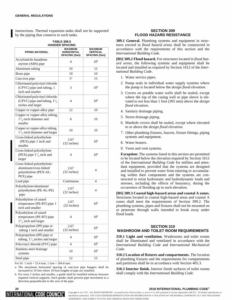
GENERAL REGULATIONS
20 2018 INTERNATIONAL PLUMBING CODE®
instructions. Thermal expansion tanks shall not be supportedby the piping that connects to such tanks.
SECTION 309 FLOOD HAZARD RESISTANCE
309.1 General. Plumbing systems and equipment in struc-tures erected in flood hazard areas shall be constructed inaccordance with the requirements of this section and theInternational Building Code.
[BS] 309.2 Flood hazard. For structures located in flood haz-ard areas, the following systems and equipment shall belocated and installed as required by Section 1612 of the Inter-national Building Code.
1. Water service pipes.
2. Pump seals in individual water supply systems wherethe pump is located below the design flood elevation.
3. Covers on potable water wells shall be sealed, exceptwhere the top of the casing well or pipe sleeve is ele-vated to not less than 1 foot (305 mm) above the designflood elevation.
4. Sanitary drainage piping.
5. Storm drainage piping.
6. Manhole covers shall be sealed, except where elevatedto or above the design flood elevation.
7. Other plumbing fixtures, faucets, fixture fittings, pipingsystems and equipment.
8. Water heaters.
9. Vents and vent systems.
Exception: The systems listed in this section are permittedto be located below the elevation required by Section 1612of the International Building Code for utilities and atten-dant equipment, provided that the systems are designedand installed to prevent water from entering or accumulat-ing within their components and the systems are con-structed to resist hydrostatic and hydrodynamic loads andstresses, including the effects of buoyancy, during theoccurrence of flooding up to such elevation.
[BS] 309.3 Coastal high-hazard areas and coastal A zones.Structures located in coastal high-hazard areas and coastal Azones shall meet the requirements of Section 309.2. Theplumbing systems, pipes and fixtures shall not be mounted onor penetrate through walls intended to break away underflood loads.
SECTION 310 WASHROOM AND TOILET ROOM REQUIREMENTS
310.1 Light and ventilation. Washrooms and toilet roomsshall be illuminated and ventilated in accordance with theInternational Building Code and International MechanicalCode.
310.2 Location of fixtures and compartments. The locationof plumbing fixtures and the requirements for compartmentsand partitions shall be in accordance with Section 405.3.
310.3 Interior finish. Interior finish surfaces of toilet roomsshall comply with the International Building Code.
TABLE 308.5 HANGER SPACING
For SI: 1 inch = 25.4 mm, 1 foot = 304.8 mm.a. The maximum horizontal spacing of cast-iron pipe hangers shall be
increased to 10 feet where 10-foot lengths of pipe are installed.b. For sizes 2 inches and smaller, a guide shall be installed midway between
required vertical supports. Such guides shall prevent pipe movement in adirection perpendicular to the axis of the pipe.
PIPING MATERIALMAXIMUM
HORIZONTAL SPACING (feet)
MAXIMUM VERTICAL
SPACING (feet)
Acrylonitrile butadiene styrene (ABS) pipe
4 10b
Aluminum tubing 10 15
Brass pipe 10 10
Cast-iron pipe 5a 15
Chlorinated polyvinyl chloride (CPVC) pipe and tubing, 1 inch and smaller
3 10b
Chlorinated polyvinyl chloride (CPVC) pipe and tubing, 11/4
inches and larger 4 10b
Copper or copper-alloy pipe 12 10
Copper or copper-alloy tubing,11/4-inch diameter andsmaller
6 10
Copper or copper-alloy tubing, 11/2-inch diameter and larger
10 10
Cross-linked polyethylene (PEX) pipe 1 inch and smaller
2.67(32 inches)
10b
Cross-linked polyethylene (PEX) pipe 11/4 inch and larger
4 10b
Cross-linked polyethylene/aluminum/cross-linkedpolyethylene (PEX-AL-PEX) pipe
2.67(32 inches) 4
Lead pipe Continuous 4
Polyethylene/aluminum/polyethylene (PE-AL-PE) pipe
2.67(32 inches)
4
Polyethylene of raisedtemperature (PE-RT) pipe 1 inch and smaller
2.67 (32 inches)
10b
Polyethylene of raised temperature (PE-RT) pipe 11/4 inch and larger
4 10b
Polypropylene (PP) pipe or tubing 1 inch and smaller
2.67(32 inches) 10b
Polypropylene (PP) pipe ortubing, 11/4 inches and larger
4 10b
Polyvinyl chloride (PVC) pipe 4 10b
Stainless steel drainagesystems
10 10b
Steel pipe 12 15
Copyright © 2017 ICC. ALL RIGHTS RESERVED. Accessed by Eric Fitch on May 15, 2018 8:17:14 AM pursuant to License Agreement with ICC. No further reproduction ordistribution authorized. ANY UNAUTHORIZED REPRODUCTION OR DISTRIBUTION IS A VIOLATION OF THE FEDERAL COPYRIGHT ACT AND THE LICENSEAGREEMENT, AND SUBJECT TO CIVIL AND CRIMINAL PENALTIES THEREUNDER.
GENERAL REGULATIONS
2018 INTERNATIONAL PLUMBING CODE® 21
SECTION 311 TOILET FACILITIES FOR WORKERS
311.1 General. Toilet facilities shall be provided for con-struction workers and such facilities shall be maintained in asanitary condition. Construction worker toilet facilities of thenonsewer type shall conform to PSAI Z4.3.
SECTION 312 TESTS AND INSPECTIONS
312.1 Required tests. The permit holder shall make theapplicable tests prescribed in Sections 312.2 through 312.10to determine compliance with the provisions of this code. Thepermit holder shall give reasonable advance notice to thecode official when the plumbing work is ready for tests. Theequipment, material, power and labor necessary for theinspection and test shall be furnished by the permit holderand he or she shall be responsible for determining that thework will withstand the test pressure prescribed in the follow-ing tests. Plumbing system piping shall be tested with eitherwater or, for piping systems other than plastic, by air. Afterthe plumbing fixtures have been set and their traps filled withwater, the entire drainage system shall be submitted to finaltests. The code official shall require the removal of any clea-nouts if necessary to ascertain whether the pressure hasreached all parts of the system.
312.1.1 Test gauges. Gauges used for testing shall be asfollows:
1. Tests requiring a pressure of 10 pounds per squareinch (psi) (69 kPa) or less shall utilize a testinggauge having increments of 0.10 psi (0.69 kPa) orless.
2. Tests requiring a pressure of greater than 10 psi (69kPa) but less than or equal to 100 psi (689 kPa) shallutilize a testing gauge having increments of 1 psi(6.9 kPa) or less.
3. Tests requiring a pressure of greater than 100 psi(689 kPa) shall utilize a testing gauge having incre-ments of 2 psi (14 kPa) or less.
312.2 Drainage and vent water test. A water test shall beapplied to the drainage system either in its entirety or in sec-tions. If applied to the entire system, all openings in the pip-ing shall be tightly closed, except the highest opening, andthe system shall be filled with water to the point of overflow.If the system is tested in sections, each opening shall betightly plugged except the highest openings of the sectionunder test, and each section shall be filled with water, but sec-tions shall not be tested with less than a 10-foot (3048 mm)head of water. In testing successive sections, not less than theupper 10 feet (3048 mm) of the next preceding section shallbe tested so that no joint or pipe in the building, except theuppermost 10 feet (3048 mm) of the system, shall have beensubmitted to a test of less than a 10-foot (3048 mm) head ofwater. This pressure shall be held for not less than 15 min-utes. The system shall then be tight at all points.
312.3 Drainage and vent air test. Plastic piping shall not betested using air. An air test shall be made by forcing air into
the system until there is a uniform gauge pressure of 5 psi(34.5 kPa) or sufficient to balance a 10-inch (254 mm) col-umn of mercury. This pressure shall be held for a test periodof not less than 15 minutes. Any adjustments to the test pres-sure required because of changes in ambient temperatures orthe seating of gaskets shall be made prior to the beginning ofthe test period.
312.4 Drainage and vent final test. The final test of thecompleted drainage and vent systems shall be visual and insufficient detail to determine compliance with the provisionsof this code. Where a smoke test is utilized, it shall be madeby filling all traps with water and then introducing into theentire system a pungent, thick smoke produced by one ormore smoke machines. When the smoke appears at stackopenings on the roof, the stack openings shall be closed and apressure equivalent to a 1-inch water column (248.8 Pa) shallbe held for a test period of not less than 15 minutes.
312.5 Water supply system test. Upon completion of a sec-tion of or the entire water supply system, the system, or por-tion completed, shall be tested and proved tight under a waterpressure not less than the working pressure of the system; or,for piping systems other than plastic, by an air test of not lessthan 50 psi (344 kPa). This pressure shall be held for not lessthan 15 minutes. The water utilized for tests shall be obtainedfrom a potable source of supply. The required tests shall beperformed in accordance with this section and Section 107.
312.6 Gravity sewer test. Gravity sewer tests shall consist ofplugging the end of the building sewer at the point of connec-tion with the public sewer, filling the building sewer withwater, testing with not less than a 10-foot (3048 mm) head ofwater and maintaining such pressure for 15 minutes.
312.7 Forced sewer test. Forced sewer tests shall consist ofplugging the end of the building sewer at the point of connec-tion with the public sewer and applying a pressure of 5 psi(34.5 kPa) greater than the pump rating, and maintaining suchpressure for 15 minutes.
312.8 Storm drainage system test. Storm drain systemswithin a building shall be tested by water or air in accordancewith Section 312.2 or 312.3.
312.9 Shower liner test. Where shower floors and receptorsare made water tight by the application of materials requiredby Section 421.5.2, the completed liner installation shall betested. The pipe from the shower drain shall be plugged watertight for the test. The floor and receptor area shall be filledwith potable water to a depth of not less than 2 inch (51 mm)measured at the threshold. Where a threshold of 2 inches (51mm) high or greater does not exist, a temporary thresholdshall be constructed to retain the test water in the lined flooror receptor area to a level not less than 2 inches (51 mm) deepmeasured at the threshold. The water shall be retained for atest period of not less than 15 minutes, and there shall not beevidence of leakage.
312.10 Inspection and testing of backflow preventionassemblies. Inspection and testing shall comply with Sec-tions 312.10.1 and 312.10.2.
312.10.1 Inspections. Annual inspections shall be madeof all backflow prevention assemblies and air gaps to
Copyright © 2017 ICC. ALL RIGHTS RESERVED. Accessed by Eric Fitch on May 15, 2018 8:17:14 AM pursuant to License Agreement with ICC. No further reproduction ordistribution authorized. ANY UNAUTHORIZED REPRODUCTION OR DISTRIBUTION IS A VIOLATION OF THE FEDERAL COPYRIGHT ACT AND THE LICENSEAGREEMENT, AND SUBJECT TO CIVIL AND CRIMINAL PENALTIES THEREUNDER.
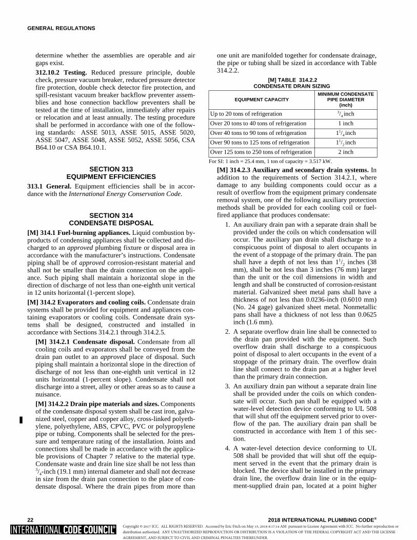
GENERAL REGULATIONS
22 2018 INTERNATIONAL PLUMBING CODE®
determine whether the assemblies are operable and airgaps exist.
312.10.2 Testing. Reduced pressure principle, doublecheck, pressure vacuum breaker, reduced pressure detectorfire protection, double check detector fire protection, andspill-resistant vacuum breaker backflow preventer assem-blies and hose connection backflow preventers shall betested at the time of installation, immediately after repairsor relocation and at least annually. The testing procedureshall be performed in accordance with one of the follow-ing standards: ASSE 5013, ASSE 5015, ASSE 5020,ASSE 5047, ASSE 5048, ASSE 5052, ASSE 5056, CSAB64.10 or CSA B64.10.1.
SECTION 313 EQUIPMENT EFFICIENCIES
313.1 General. Equipment efficiencies shall be in accor-dance with the International Energy Conservation Code.
SECTION 314 CONDENSATE DISPOSAL
[M] 314.1 Fuel-burning appliances. Liquid combustion by-products of condensing appliances shall be collected and dis-charged to an approved plumbing fixture or disposal area inaccordance with the manufacturer’s instructions. Condensatepiping shall be of approved corrosion-resistant material andshall not be smaller than the drain connection on the appli-ance. Such piping shall maintain a horizontal slope in thedirection of discharge of not less than one-eighth unit verticalin 12 units horizontal (1-percent slope).
[M] 314.2 Evaporators and cooling coils. Condensate drainsystems shall be provided for equipment and appliances con-taining evaporators or cooling coils. Condensate drain sys-tems shall be designed, constructed and installed inaccordance with Sections 314.2.1 through 314.2.5.
[M] 314.2.1 Condensate disposal. Condensate from allcooling coils and evaporators shall be conveyed from thedrain pan outlet to an approved place of disposal. Suchpiping shall maintain a horizontal slope in the direction ofdischarge of not less than one-eighth unit vertical in 12units horizontal (1-percent slope). Condensate shall notdischarge into a street, alley or other areas so as to cause anuisance.
[M] 314.2.2 Drain pipe materials and sizes. Componentsof the condensate disposal system shall be cast iron, galva-nized steel, copper and copper alloy, cross-linked polyeth-ylene, polyethylene, ABS, CPVC, PVC or polypropylenepipe or tubing. Components shall be selected for the pres-sure and temperature rating of the installation. Joints andconnections shall be made in accordance with the applica-ble provisions of Chapter 7 relative to the material type.Condensate waste and drain line size shall be not less than3/4-inch (19.1 mm) internal diameter and shall not decreasein size from the drain pan connection to the place of con-densate disposal. Where the drain pipes from more than
one unit are manifolded together for condensate drainage,the pipe or tubing shall be sized in accordance with Table314.2.2.
[M] TABLE 314.2.2 CONDENSATE DRAIN SIZING
For SI: 1 inch = 25.4 mm, 1 ton of capacity = 3.517 kW.
[M] 314.2.3 Auxiliary and secondary drain systems. Inaddition to the requirements of Section 314.2.1, wheredamage to any building components could occur as aresult of overflow from the equipment primary condensateremoval system, one of the following auxiliary protectionmethods shall be provided for each cooling coil or fuel-fired appliance that produces condensate:
1. An auxiliary drain pan with a separate drain shall beprovided under the coils on which condensation willoccur. The auxiliary pan drain shall discharge to aconspicuous point of disposal to alert occupants inthe event of a stoppage of the primary drain. The panshall have a depth of not less than 11/2 inches (38mm), shall be not less than 3 inches (76 mm) largerthan the unit or the coil dimensions in width andlength and shall be constructed of corrosion-resistantmaterial. Galvanized sheet metal pans shall have athickness of not less than 0.0236-inch (0.6010 mm)(No. 24 gage) galvanized sheet metal. Nonmetallicpans shall have a thickness of not less than 0.0625inch (1.6 mm).
2. A separate overflow drain line shall be connected tothe drain pan provided with the equipment. Suchoverflow drain shall discharge to a conspicuouspoint of disposal to alert occupants in the event of astoppage of the primary drain. The overflow drainline shall connect to the drain pan at a higher levelthan the primary drain connection.
3. An auxiliary drain pan without a separate drain lineshall be provided under the coils on which conden-sate will occur. Such pan shall be equipped with awater-level detection device conforming to UL 508that will shut off the equipment served prior to over-flow of the pan. The auxiliary drain pan shall beconstructed in accordance with Item 1 of this sec-tion.
4. A water-level detection device conforming to UL508 shall be provided that will shut off the equip-ment served in the event that the primary drain isblocked. The device shall be installed in the primarydrain line, the overflow drain line or in the equip-ment-supplied drain pan, located at a point higher
EQUIPMENT CAPACITYMINIMUM CONDENSATE
PIPE DIAMETER(inch)
Up to 20 tons of refrigeration 3/4 inch
Over 20 tons to 40 tons of refrigeration 1 inch
Over 40 tons to 90 tons of refrigeration 11/4 inch
Over 90 tons to 125 tons of refrigeration 11/2 inch
Over 125 tons to 250 tons of refrigeration 2 inch
Copyright © 2017 ICC. ALL RIGHTS RESERVED. Accessed by Eric Fitch on May 15, 2018 8:17:14 AM pursuant to License Agreement with ICC. No further reproduction ordistribution authorized. ANY UNAUTHORIZED REPRODUCTION OR DISTRIBUTION IS A VIOLATION OF THE FEDERAL COPYRIGHT ACT AND THE LICENSEAGREEMENT, AND SUBJECT TO CIVIL AND CRIMINAL PENALTIES THEREUNDER.

GENERAL REGULATIONS
2018 INTERNATIONAL PLUMBING CODE® 23
than the primary drain line connection and below theoverflow rim of such pan.
Exception: Fuel-fired appliances that automati-cally shut down operation in the event of a stop-page in the condensate drainage system.
[M] 314.2.3.1 Water-level monitoring devices. Ondown-flow units and all other coils that do not have asecondary drain or provisions to install a secondary orauxiliary drain pan, a water-level monitoring deviceshall be installed inside the primary drain pan. Thisdevice shall shut off the equipment served in the eventthat the primary drain becomes restricted. Devicesinstalled in the drain line shall not be permitted.
[M] 314.2.3.2 Appliance, equipment and insulationin pans. Where appliances, equipment or insulation aresubject to water damage when auxiliary drain pans fillsuch portions of the appliances, equipment and insula-tion shall be installed above the flood level rim of thepan. Supports located inside of the pan to support theappliance or equipment shall be water resistant andapproved.
[M] 314.2.4 Traps. Condensate drains shall be trapped asrequired by the equipment or appliance manufacturer.
[M] 314.2.4.1 Ductless mini-split system traps. Duct-less mini-split equipment that produces condensationshall be provided with an in-line check valve located inthe drain line or a trap.
[M] 314.2.5 Drain line maintenance. Condensate drainlines shall be configured to permit the clearing of block-ages and performance of maintenance without requiringthe drain line to be cut.
SECTION 315PENETRATIONS
315.1 Sealing of annular spaces. The annular space betweenthe outside of a pipe and the inside of a pipe sleeve orbetween the outside of a pipe and an opening in a buildingenvelope wall, floor, or ceiling assembly penetrated by a pipeshall be sealed in an approved manner with caulking material,foam sealant or closed with a gasketing system. The caulkingmaterial, foam sealant or gasketing system shall be designedfor the conditions at the penetration location and shall becompatible with the pipe, sleeve and building materials incontact with the sealing materials. Annular spaces created bypipes penetrating fire-resistance-rated assemblies or mem-branes of such assemblies shall be sealed or closed in accor-dance with Section 714 of the International Building Code.
SECTION 316 ALTERNATIVE ENGINEERED DESIGN
316.1 Alternative engineered design. The design, documen-tation, inspection, testing and approval of an alternative engi-neered design plumbing system shall comply with Sections316.1.1 through 316.1.6.
316.1.1 Design criteria. An alternative engineered designshall conform to the intent of the provisions of this codeand shall provide an equivalent level of quality, strength,effectiveness, fire resistance, durability and safety. Mate-rial, equipment or components shall be designed andinstalled in accordance with the manufacturer’s instruc-tions.
316.1.2 Submittal. The registered design professionalshall indicate on the permit application that the plumbingsystem is an alternative engineered design. The permitand permanent permit records shall indicate that an alter-native engineered design was part of the approved instal-lation.
316.1.3 Technical data. The registered design profes-sional shall submit sufficient technical data to substantiatethe proposed alternative engineered design and to provethat the performance meets the intent of this code.
316.1.4 Construction documents. The registered designprofessional shall submit to the code official two completesets of signed and sealed construction documents for thealternative engineering design. The construction docu-ments shall include floor plans and a riser diagram of thework. Where appropriate, the construction documentsshall indicate the direction of flow, all pipe sizes, grade ofhorizontal piping, loading and location of fixtures andappliances.
316.1.5 Design approval. Where the code official deter-mines that the alternative engineered design conforms tothe intent of this code, the plumbing system shall beapproved. If the alternative engineered design is notapproved, the code official shall notify the registereddesign professional in writing, stating the reasons thereof.
316.1.6 Inspection and testing. The alternative engi-neered design shall be tested and inspected in accordancewith the requirements of Sections 107 and 312.
Copyright © 2017 ICC. ALL RIGHTS RESERVED. Accessed by Eric Fitch on May 15, 2018 8:17:14 AM pursuant to License Agreement with ICC. No further reproduction ordistribution authorized. ANY UNAUTHORIZED REPRODUCTION OR DISTRIBUTION IS A VIOLATION OF THE FEDERAL COPYRIGHT ACT AND THE LICENSEAGREEMENT, AND SUBJECT TO CIVIL AND CRIMINAL PENALTIES THEREUNDER.

24 2018 INTERNATIONAL PLUMBING CODE®
Copyright © 2017 ICC. ALL RIGHTS RESERVED. Accessed by Eric Fitch on May 15, 2018 8:17:14 AM pursuant to License Agreement with ICC. No further reproduction ordistribution authorized. ANY UNAUTHORIZED REPRODUCTION OR DISTRIBUTION IS A VIOLATION OF THE FEDERAL COPYRIGHT ACT AND THE LICENSEAGREEMENT, AND SUBJECT TO CIVIL AND CRIMINAL PENALTIES THEREUNDER.
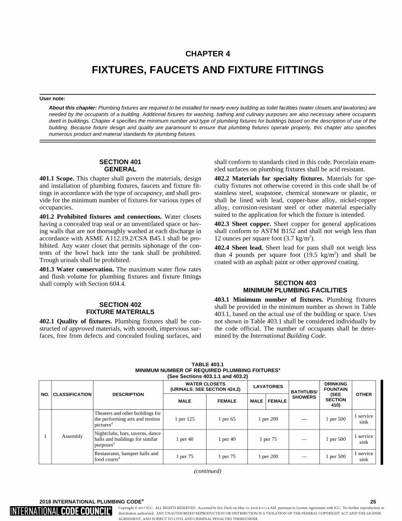
2018 INTERNATIONAL PLUMBING CODE® 25
TABLE 403.1 MINIMUM NUMBER OF REQUIRED PLUMBING FIXTURESa
(See Sections 403.1.1 and 403.2)
(continued)
NO. CLASSIFICATION DESCRIPTION
WATER CLOSETS (URINALS: SEE SECTION 424.2) LAVATORIES
BATHTUBS/ SHOWERS
DRINKING FOUNTAIN
(SEE SECTION
410)
OTHERMALE FEMALE MALE FEMALE
1 Assembly
Theaters and other buildings for the performing arts and motion picturesd
1 per 125 1 per 65 1 per 200 — 1 per 500 1 service
sink
Nightclubs, bars, taverns, dance halls and buildings for similar purposesd
1 per 40 1 per 40 1 per 75 — 1 per 500 1 service
sink
Restaurants, banquet halls and food courtsd 1 per 75 1 per 75 1 per 200 — 1 per 500
1 service sink
CHAPTER 4
FIXTURES, FAUCETS AND FIXTURE FITTINGS
User note:
About this chapter: Plumbing fixtures are required to be installed for nearly every building as toilet facilities (water closets and lavatories) areneeded by the occupants of a building. Additional fixtures for washing, bathing and culinary purposes are also necessary where occupantsdwell in buildings. Chapter 4 specifies the minimum number and type of plumbing fixtures for buildings based on the description of use of thebuilding. Because fixture design and quality are paramount to ensure that plumbing fixtures operate properly, this chapter also specifiesnumerous product and material standards for plumbing fixtures.
SECTION 401 GENERAL
401.1 Scope. This chapter shall govern the materials, designand installation of plumbing fixtures, faucets and fixture fit-tings in accordance with the type of occupancy, and shall pro-vide for the minimum number of fixtures for various types ofoccupancies.
401.2 Prohibited fixtures and connections. Water closetshaving a concealed trap seal or an unventilated space or hav-ing walls that are not thoroughly washed at each discharge inaccordance with ASME A112.19.2/CSA B45.1 shall be pro-hibited. Any water closet that permits siphonage of the con-tents of the bowl back into the tank shall be prohibited.Trough urinals shall be prohibited.
401.3 Water conservation. The maximum water flow ratesand flush volume for plumbing fixtures and fixture fittingsshall comply with Section 604.4.
SECTION 402 FIXTURE MATERIALS
402.1 Quality of fixtures. Plumbing fixtures shall be con-structed of approved materials, with smooth, impervious sur-faces, free from defects and concealed fouling surfaces, and
shall conform to standards cited in this code. Porcelain enam-eled surfaces on plumbing fixtures shall be acid resistant.
402.2 Materials for specialty fixtures. Materials for spe-cialty fixtures not otherwise covered in this code shall be ofstainless steel, soapstone, chemical stoneware or plastic, orshall be lined with lead, copper-base alloy, nickel-copperalloy, corrosion-resistant steel or other material especiallysuited to the application for which the fixture is intended.
402.3 Sheet copper. Sheet copper for general applicationsshall conform to ASTM B152 and shall not weigh less than12 ounces per square foot (3.7 kg/m2).
402.4 Sheet lead. Sheet lead for pans shall not weigh lessthan 4 pounds per square foot (19.5 kg/m2) and shall becoated with an asphalt paint or other approved coating.
SECTION 403 MINIMUM PLUMBING FACILITIES
403.1 Minimum number of fixtures. Plumbing fixturesshall be provided in the minimum number as shown in Table403.1, based on the actual use of the building or space. Usesnot shown in Table 403.1 shall be considered individually bythe code official. The number of occupants shall be deter-mined by the International Building Code.
Copyright © 2017 ICC. ALL RIGHTS RESERVED. Accessed by Eric Fitch on May 15, 2018 8:17:14 AM pursuant to License Agreement with ICC. No further reproduction ordistribution authorized. ANY UNAUTHORIZED REPRODUCTION OR DISTRIBUTION IS A VIOLATION OF THE FEDERAL COPYRIGHT ACT AND THE LICENSEAGREEMENT, AND SUBJECT TO CIVIL AND CRIMINAL PENALTIES THEREUNDER.
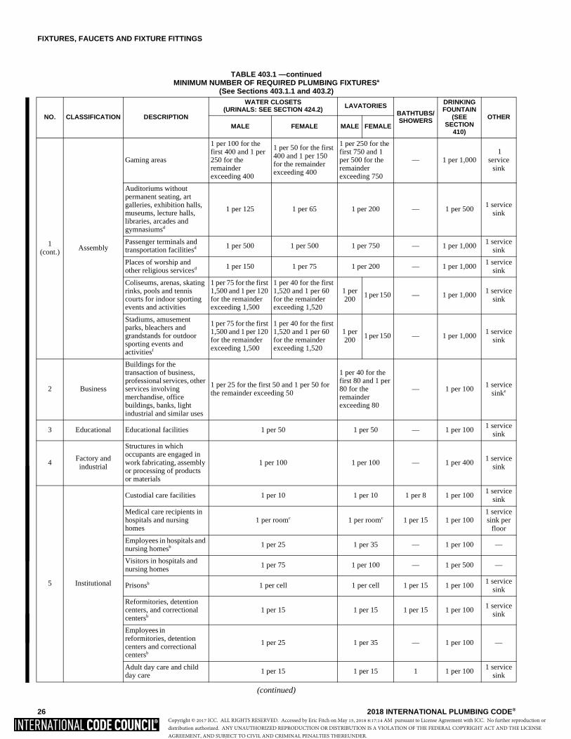
FIXTURES, FAUCETS AND FIXTURE FITTINGS
26 2018 INTERNATIONAL PLUMBING CODE®
TABLE 403.1 —continuedMINIMUM NUMBER OF REQUIRED PLUMBING FIXTURESa
(See Sections 403.1.1 and 403.2)
(continued)
NO. CLASSIFICATION DESCRIPTION
WATER CLOSETS (URINALS: SEE SECTION 424.2) LAVATORIES
BATHTUBS/ SHOWERS
DRINKING FOUNTAIN
(SEE SECTION
410)
OTHERMALE FEMALE MALE FEMALE
1(cont.)
Assembly
Gaming areas
1 per 100 for the first 400 and 1 per 250 for the remainder exceeding 400
1 per 50 for the first 400 and 1 per 150 for the remainder exceeding 400
1 per 250 for the first 750 and 1 per 500 for the remainder exceeding 750
— 1 per 1,000 1
service sink
Auditoriums without permanent seating, art galleries, exhibition halls, museums, lecture halls, libraries, arcades and gymnasiumsd
1 per 125 1 per 65 1 per 200 — 1 per 500 1 service
sink
Passenger terminals and transportation facilitiesd 1 per 500 1 per 500 1 per 750 — 1 per 1,000
1 service sink
Places of worship and other religious servicesd 1 per 150 1 per 75 1 per 200 — 1 per 1,000
1 service sink
Coliseums, arenas, skating rinks, pools and tennis courts for indoor sporting events and activities
1 per 75 for the first 1,500 and 1 per 120 for the remainder exceeding 1,500
1 per 40 for the first 1,520 and 1 per 60 for the remainder exceeding 1,520
1 per 200
1 per 150 — 1 per 1,000 1 service
sink
Stadiums, amusement parks, bleachers and grandstands for outdoor sporting events and activitiesf
1 per 75 for the first 1,500 and 1 per 120 for the remainder exceeding 1,500
1 per 40 for the first 1,520 and 1 per 60 for the remainder exceeding 1,520
1 per 200
1 per 150 — 1 per 1,000 1 service
sink
2 Business
Buildings for the transaction of business, professional services, other services involving merchandise, office buildings, banks, light industrial and similar uses
1 per 25 for the first 50 and 1 per 50 for the remainder exceeding 50
1 per 40 for the first 80 and 1 per 80 for the remainder exceeding 80
— 1 per 100 1 service
sinke
3 Educational Educational facilities 1 per 50 1 per 50 — 1 per 100 1 service
sink
4 Factory and industrial
Structures in which occupants are engaged in work fabricating, assembly or processing of products or materials
1 per 100 1 per 100 — 1 per 400 1 service
sink
5 Institutional
Custodial care facilities 1 per 10 1 per 10 1 per 8 1 per 100 1 service
sink
Medical care recipients in hospitals and nursing homes
1 per roomc 1 per roomc 1 per 15 1 per 1001 service sink per
floor
Employees in hospitals and nursing homesb 1 per 25 1 per 35 — 1 per 100 —
Visitors in hospitals and nursing homes
1 per 75 1 per 100 — 1 per 500 —
Prisonsb 1 per cell 1 per cell 1 per 15 1 per 100 1 service
sink
Reformitories, detention centers, and correctional centersb
1 per 15 1 per 15 1 per 15 1 per 100 1 service
sink
Employees in reformitories, detention centers and correctional centersb
1 per 25 1 per 35 — 1 per 100 —
Adult day care and child day care
1 per 15 1 per 15 1 1 per 1001 service
sink
Copyright © 2017 ICC. ALL RIGHTS RESERVED. Accessed by Eric Fitch on May 15, 2018 8:17:14 AM pursuant to License Agreement with ICC. No further reproduction ordistribution authorized. ANY UNAUTHORIZED REPRODUCTION OR DISTRIBUTION IS A VIOLATION OF THE FEDERAL COPYRIGHT ACT AND THE LICENSEAGREEMENT, AND SUBJECT TO CIVIL AND CRIMINAL PENALTIES THEREUNDER.
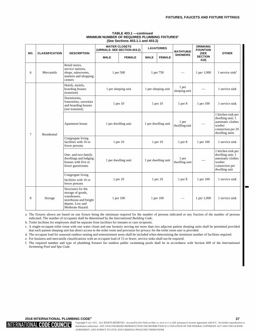
FIXTURES, FAUCETS AND FIXTURE FITTINGS
2018 INTERNATIONAL PLUMBING CODE® 27
TABLE 403.1 —continuedMINIMUM NUMBER OF REQUIRED PLUMBING FIXTURESa
(See Sections 403.1.1 and 403.2)
a. The fixtures shown are based on one fixture being the minimum required for the number of persons indicated or any fraction of the number of personsindicated. The number of occupants shall be determined by the International Building Code.
b. Toilet facilities for employees shall be separate from facilities for inmates or care recipients.c. A single-occupant toilet room with one water closet and one lavatory serving not more than two adjacent patient sleeping units shall be permitted provided
that each patient sleeping unit has direct access to the toilet room and provision for privacy for the toilet room user is provided.d. The occupant load for seasonal outdoor seating and entertainment areas shall be included when determining the minimum number of facilities required.e. For business and mercantile classifications with an occupant load of 15 or fewer, service sinks shall not be required.f. The required number and type of plumbing fixtures for outdoor public swimming pools shall be in accordance with Section 609 of the International
Swimming Pool and Spa Code.
NO. CLASSIFICATION DESCRIPTION
WATER CLOSETS (URINALS: SEE SECTION 424.2) LAVATORIES
BATHTUBS/ SHOWERS
DRINKING FOUNTAIN
(SEE SECTION
410)
OTHER MALE FEMALE MALE FEMALE
6 Mercantile
Retail stores, service stations, shops, salesrooms, markets and shopping centers
1 per 500 1 per 750 — 1 per 1,000 1 service sinke
7 Residential
Hotels, motels, boarding houses (transient)
1 per sleeping unit 1 per sleeping unit 1 per
sleeping unit — 1 service sink
Dormitories, fraternities, sororities and boarding houses (not transient)
1 per 10 1 per 10 1 per 8 1 per 100 1 service sink
Apartment house 1 per dwelling unit 1 per dwelling unit 1 per
dwelling unit —
1 kitchen sink per dwelling unit; 1 automatic clothes washer connection per 20 dwelling units
Congregate living facilities with 16 or fewer persons
1 per 10 1 per 10 1 per 8 1 per 100 1 service sink
One- and two-family dwellings and lodging houses with five or fewer guestrooms
1 per dwelling unit 1 per dwelling unit1 per
dwelling unit—
1 kitchen sink per dwelling unit; 1 automatic clothes washer connection per dwelling unit
Congregate living
facilities with 16 or fewer persons
1 per 10 1 per 10 1 per 8 1 per 100 1 service sink
8 Storage
Structures for the storage of goods, warehouses, storehouse and freight depots. Low and Moderate Hazard.
1 per 100 1 per 100 — 1 per 1,000 1 service sink
�
Copyright © 2017 ICC. ALL RIGHTS RESERVED. Accessed by Eric Fitch on May 15, 2018 8:17:14 AM pursuant to License Agreement with ICC. No further reproduction ordistribution authorized. ANY UNAUTHORIZED REPRODUCTION OR DISTRIBUTION IS A VIOLATION OF THE FEDERAL COPYRIGHT ACT AND THE LICENSEAGREEMENT, AND SUBJECT TO CIVIL AND CRIMINAL PENALTIES THEREUNDER.
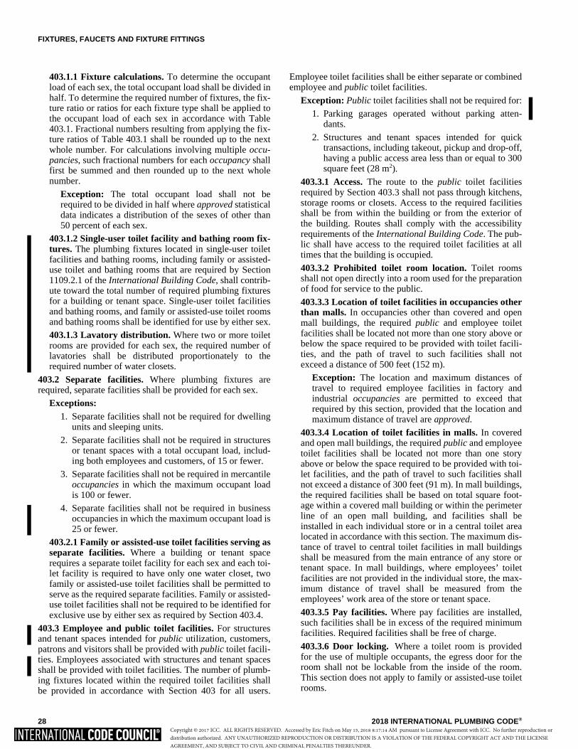
FIXTURES, FAUCETS AND FIXTURE FITTINGS
28 2018 INTERNATIONAL PLUMBING CODE®
403.1.1 Fixture calculations. To determine the occupantload of each sex, the total occupant load shall be divided inhalf. To determine the required number of fixtures, the fix-ture ratio or ratios for each fixture type shall be applied tothe occupant load of each sex in accordance with Table403.1. Fractional numbers resulting from applying the fix-ture ratios of Table 403.1 shall be rounded up to the nextwhole number. For calculations involving multiple occu-pancies, such fractional numbers for each occupancy shallfirst be summed and then rounded up to the next wholenumber.
Exception: The total occupant load shall not berequired to be divided in half where approved statisticaldata indicates a distribution of the sexes of other than50 percent of each sex.
403.1.2 Single-user toilet facility and bathing room fix-tures. The plumbing fixtures located in single-user toiletfacilities and bathing rooms, including family or assisted-use toilet and bathing rooms that are required by Section1109.2.1 of the International Building Code, shall contrib-ute toward the total number of required plumbing fixturesfor a building or tenant space. Single-user toilet facilitiesand bathing rooms, and family or assisted-use toilet roomsand bathing rooms shall be identified for use by either sex.
403.1.3 Lavatory distribution. Where two or more toiletrooms are provided for each sex, the required number oflavatories shall be distributed proportionately to therequired number of water closets.
403.2 Separate facilities. Where plumbing fixtures arerequired, separate facilities shall be provided for each sex.
Exceptions:1. Separate facilities shall not be required for dwelling
units and sleeping units.
2. Separate facilities shall not be required in structuresor tenant spaces with a total occupant load, includ-ing both employees and customers, of 15 or fewer.
3. Separate facilities shall not be required in mercantileoccupancies in which the maximum occupant loadis 100 or fewer.
4. Separate facilities shall not be required in businessoccupancies in which the maximum occupant load is25 or fewer.
403.2.1 Family or assisted-use toilet facilities serving asseparate facilities. Where a building or tenant spacerequires a separate toilet facility for each sex and each toi-let facility is required to have only one water closet, twofamily or assisted-use toilet facilities shall be permitted toserve as the required separate facilities. Family or assisted-use toilet facilities shall not be required to be identified forexclusive use by either sex as required by Section 403.4.
403.3 Employee and public toilet facilities. For structuresand tenant spaces intended for public utilization, customers,patrons and visitors shall be provided with public toilet facili-ties. Employees associated with structures and tenant spacesshall be provided with toilet facilities. The number of plumb-ing fixtures located within the required toilet facilities shallbe provided in accordance with Section 403 for all users.
Employee toilet facilities shall be either separate or combinedemployee and public toilet facilities.
Exception: Public toilet facilities shall not be required for:
1. Parking garages operated without parking atten-dants.
2. Structures and tenant spaces intended for quicktransactions, including takeout, pickup and drop-off,having a public access area less than or equal to 300square feet (28 m2).
403.3.1 Access. The route to the public toilet facilitiesrequired by Section 403.3 shall not pass through kitchens,storage rooms or closets. Access to the required facilitiesshall be from within the building or from the exterior ofthe building. Routes shall comply with the accessibilityrequirements of the International Building Code. The pub-lic shall have access to the required toilet facilities at alltimes that the building is occupied.
403.3.2 Prohibited toilet room location. Toilet roomsshall not open directly into a room used for the preparationof food for service to the public.
403.3.3 Location of toilet facilities in occupancies otherthan malls. In occupancies other than covered and openmall buildings, the required public and employee toiletfacilities shall be located not more than one story above orbelow the space required to be provided with toilet facili-ties, and the path of travel to such facilities shall notexceed a distance of 500 feet (152 m).
Exception: The location and maximum distances oftravel to required employee facilities in factory andindustrial occupancies are permitted to exceed thatrequired by this section, provided that the location andmaximum distance of travel are approved.
403.3.4 Location of toilet facilities in malls. In coveredand open mall buildings, the required public and employeetoilet facilities shall be located not more than one storyabove or below the space required to be provided with toi-let facilities, and the path of travel to such facilities shallnot exceed a distance of 300 feet (91 m). In mall buildings,the required facilities shall be based on total square foot-age within a covered mall building or within the perimeterline of an open mall building, and facilities shall beinstalled in each individual store or in a central toilet arealocated in accordance with this section. The maximum dis-tance of travel to central toilet facilities in mall buildingsshall be measured from the main entrance of any store ortenant space. In mall buildings, where employees’ toiletfacilities are not provided in the individual store, the max-imum distance of travel shall be measured from theemployees’ work area of the store or tenant space.
403.3.5 Pay facilities. Where pay facilities are installed,such facilities shall be in excess of the required minimumfacilities. Required facilities shall be free of charge.
403.3.6 Door locking. Where a toilet room is providedfor the use of multiple occupants, the egress door for theroom shall not be lockable from the inside of the room.This section does not apply to family or assisted-use toiletrooms.
Copyright © 2017 ICC. ALL RIGHTS RESERVED. Accessed by Eric Fitch on May 15, 2018 8:17:14 AM pursuant to License Agreement with ICC. No further reproduction ordistribution authorized. ANY UNAUTHORIZED REPRODUCTION OR DISTRIBUTION IS A VIOLATION OF THE FEDERAL COPYRIGHT ACT AND THE LICENSEAGREEMENT, AND SUBJECT TO CIVIL AND CRIMINAL PENALTIES THEREUNDER.
FIXTURES, FAUCETS AND FIXTURE FITTINGS
2018 INTERNATIONAL PLUMBING CODE® 29
403.4 Signage. Required public facilities shall be providedwith signs that designate the sex, as required by Section403.2. Signs shall be readily visible and located near theentrance to each toilet facility. Signs for accessible toiletfacilities shall comply with Section 1111 of the InternationalBuilding Code.
403.4.1 Directional signage. Directional signage indicat-ing the route to the required public toilet facilities shall beposted in a lobby, corridor, aisle or similar space, such thatthe sign can be readily seen from the main entrance to thebuilding or tenant space.
403.5 Drinking fountain location. Drinking fountains shallnot be required to be located in individual tenant spaces pro-vided that public drinking fountains are located within a dis-tance of travel of 500 feet (152 m) of the most remotelocation in the tenant space and not more than one storyabove or below the tenant space. Where the tenant space is ina covered or open mall, such distance shall not exceed 300feet (91 m). Drinking fountains shall be located on an accessi-ble route.
SECTION 404 ACCESSIBLE PLUMBING FACILITIES
404.1 Where required. Accessible plumbing facilities andfixtures shall be provided in accordance with the Interna-tional Building Code.
404.2 Accessible fixture requirements. Accessible plumb-ing fixtures shall be installed with the clearances, heights,spacings and arrangements in accordance with ICC A117.1.
404.3 Exposed pipes and surfaces. Water supply and drainpipes under accessible lavatories and sinks shall be coveredor otherwise configured to protect against contact. Pipe cov-erings shall comply with ASME A112.18.9.
SECTION 405 INSTALLATION OF FIXTURES
405.1 Water supply protection. The supply lines and fit-tings for every plumbing fixture shall be installed so as toprevent backflow.
405.2 Access for cleaning. Plumbing fixtures shall beinstalled so as to afford easy access for cleaning both the fix-ture and the area around the fixture.
405.3 Setting. Fixtures shall be set level and in proper align-ment with reference to adjacent walls.
405.3.1 Water closets, urinals, lavatories and bidets. Awater closet, urinal, lavatory or bidet shall not be set closerthan 15 inches (381 mm) from its center to any side wall,partition, vanity or other obstruction. Where partitions orother obstructions do not separate adjacent fixtures, fix-tures shall not be set closer than 30 inches (762 mm) cen-ter to center between adjacent fixtures. There shall be notless than a 21-inch (533 mm) clearance in front of a watercloset, urinal, lavatory or bidet to any wall, fixture or door.Water closet compartments shall be not less than 30 inches(762 mm) in width and not less than 60 inches (1524 mm)
in depth for floor-mounted water closets and not less than30 inches (762 mm) in width and 56 inches (1422 mm) indepth for wall-hung water closets.
Exception: An accessible children’s water closet shallbe set not closer than 12 inches (305 mm) from its cen-ter to the required partition or to the wall on one side.
405.3.2 Public lavatories. In employee and public toiletrooms, the required lavatory shall be located in the sameroom as the required water closet.
405.3.3 Location of fixtures and piping. Piping, fixturesor equipment shall not be located in such a manner as tointerfere with the normal operation of windows, doors orother means of egress openings. 405.3.4 Water closet compartment. Each water closetutilized by the public or employees shall occupy a separatecompartment with walls or partitions and a door enclosingthe fixtures to ensure privacy.
Exceptions:1. Water closet compartments shall not be required
in a single-occupant toilet room with a lockabledoor.
2. Toilet rooms located in child day care facilitiesand containing two or more water closets shall bepermitted to have one water closet without anenclosing compartment.
3. This provision is not applicable to toilet areaslocated within Group I-3 housing areas.
405.3.5 Urinal partitions. Each urinal utilized by the pub-lic or employees shall occupy a separate area with walls orpartitions to provide privacy. The horizontal dimensionbetween walls or partitions at each urinal shall be not lessthan 30 inches (762 mm). The walls or partitions shallbegin at a height not greater than 12 inches (305 mm) fromand extend not less than 60 inches (1524 mm) above thefinished floor surface. The walls or partitions shall extendfrom the wall surface at each side of the urinal not lessthan 18 inches (457 mm) or to a point not less than 6inches (152 mm) beyond the outermost front lip of the uri-nal measured from the finished backwall surface, which-ever is greater.
Exceptions:1. Urinal partitions shall not be required in a single-
occupant or family/assisted-use toilet room witha lockable door.
2. Toilet rooms located in child day care facilitiesand containing two or more urinals shall be per-mitted to have one urinal without partitions.
405.4 Floor and wall drainage connections. Connectionsbetween the drain and floor outlet plumbing fixtures shall bemade with a floor flange or a waste connector and sealinggasket. The waste connector and sealing gasket joint shallcomply with the joint tightness test of ASME A112.4.3 andshall be installed in accordance with the manufacturer’sinstructions. The flange shall be attached to the drain andanchored to the structure. Connections between the drain and
Copyright © 2017 ICC. ALL RIGHTS RESERVED. Accessed by Eric Fitch on May 15, 2018 8:17:14 AM pursuant to License Agreement with ICC. No further reproduction ordistribution authorized. ANY UNAUTHORIZED REPRODUCTION OR DISTRIBUTION IS A VIOLATION OF THE FEDERAL COPYRIGHT ACT AND THE LICENSEAGREEMENT, AND SUBJECT TO CIVIL AND CRIMINAL PENALTIES THEREUNDER.
FIXTURES, FAUCETS AND FIXTURE FITTINGS
30 2018 INTERNATIONAL PLUMBING CODE®
wall-hung water closets shall be made with an approvedextension nipple or horn adaptor. The water closet shall bebolted to the hanger with corrosion-resistant bolts or screws.Joints shall be sealed with an approved elastomeric gasket,flange-to-fixture connection complying with ASMEA112.4.3 or an approved setting compound.
405.4.1 Floor flanges. Floor flanges for water closets orsimilar fixtures shall be not less than 0.125 inch (3.2 mm)thick for copper alloy, 0.25 inch (6.4 mm) thick for plasticand 0.25 inch (6.4 mm) thick and not less than a 2-inch (51mm) caulking depth for cast iron or galvanized malleableiron.
Floor flanges of hard lead shall weigh not less than 1pound, 9 ounces (0.7 kg) and shall be composed of leadalloy with not less than 7.75-percent antimony by weight.Closet screws and bolts shall be of copper alloy. Flangesshall be secured to the building structure with corrosion-resistant screws or bolts.
405.4.2 Securing floor outlet fixtures. Floor outlet fix-tures shall be secured to the floor or floor flanges byscrews or bolts of corrosion-resistant material.
405.4.3 Securing wall-hung water closet bowls. Wall-hung water closet bowls shall be supported by a concealedmetal carrier that is attached to the building structuralmembers so that strain is not transmitted to the closet con-nector or any other part of the plumbing system. The car-rier shall conform to ASME A112.6.2.
405.5 Plumbing fixtures with a pumped waste. Plumbingfixtures with a pumped waste shall comply with ASMEA112.3.4/CSA B45.9. The plumbing fixture with a pumpedwaste shall be installed in accordance with the manufac-turer’s instructions.
405.6 Water-tight joints. Joints formed where fixtures comein contact with walls or floors shall be sealed.
405.7 Plumbing in mental health centers. In mental healthcenters, pipes or traps shall not be exposed, and fixtures shallbe bolted through walls.
405.8 Design of overflows. Where any fixture is providedwith an overflow, the waste shall be designed and installed sothat standing water in the fixture will not rise in the overflowwhen the stopper is closed, and water will not remain in theoverflow when the fixture is empty.
405.8.1 Connection of overflows. The overflow from anyfixture shall discharge into the drainage system on the inletor fixture side of the trap.
Exception: The overflow from a flush tank serving awater closet or urinal shall discharge into the fixtureserved.
405.9 Slip joint connections. Slip joints shall be made withan approved elastomeric gasket and shall only be installed onthe trap outlet, trap inlet and within the trap seal. Fixtureswith concealed slip-joint connections shall be provided withan access panel or utility space not less than 12 inches (305mm) in its smallest dimension or other approved arrangementso as to provide access to the slip joint connections forinspection and repair.
405.10 Design and installation of plumbing fixtures. Inte-gral fixture fitting mounting surfaces on manufacturedplumbing fixtures or plumbing fixtures constructed on siteshall meet the design requirements of ASME A112.19.2/CSAB45.1 or ASME A112.19.3/CSA B45.4.
SECTION 406 AUTOMATIC CLOTHES WASHERS
406.1 Water connection. The water supply to an automaticclothes washer shall be protected against backflow by an airgap that is integral with the machine or a backflow preventershall be installed in accordance with Section 608. Air gapsshall comply with ASME A112.1.2 or A112.1.3.
406.2 Waste connection. The waste from an automaticclothes washer shall discharge through an air break into astandpipe in accordance with Section 802.3.3 or into a laun-dry sink. The trap and fixture drain for an automatic clotheswasher standpipe shall be not less than 2 inches (51 mm) indiameter. The fixture drain for the standpipe serving an auto-matic clothes washer shall connect to a 3-inch (76 mm) orlarger diameter fixture branch or stack. Automatic clotheswashers that discharge by gravity shall be permitted to drainto a waste receptor or an approved trench drain.
SECTION 407 BATHTUBS
407.1 Approval. Bathtubs shall conform to ASME A112.19.1/CSA B45.2, ASME A112.19.2/CSA B45.1, ASME A112.19.3/CSA B45.4 or CSA B45.5/IAPMO Z124.
407.2 Bathtub waste outlets and overflows. Bathtubs shallbe equipped with a waste outlet and an overflow outlet. Theoutlets shall be connected to waste tubing or piping not lessthan 11/2 inches (38 mm) in diameter. The waste outlet shallbe equipped with a water-tight stopper.
407.3 Glazing. Windows and doors within a bathtub enclo-sure shall conform to the safety glazing requirements of theInternational Building Code.
407.4 Bathtub enclosure. Doors in a bathtub enclosure shallconform to ASME A112.19.15.
SECTION 408 BIDETS
408.1 Approval. Bidets shall conform to ASME A112.19.2/CSA B45.1.
408.2 Water connection. The water supply to a bidet shall beprotected against backflow by an air gap or backflow pre-venter in accordance with Section 608.13.1, 608.13.2,608.13.3, 608.13.5, 608.13.6 or 608.13.8.
408.3 Bidet water temperature. The discharge water tem-perature from a bidet fitting shall be limited to not greaterthan 110°F (43°C) by a water-temperature-limiting deviceconforming to ASSE 1070/ASME A112.1070/CSA B125.70or CSA B125.3.
Copyright © 2017 ICC. ALL RIGHTS RESERVED. Accessed by Eric Fitch on May 15, 2018 8:17:14 AM pursuant to License Agreement with ICC. No further reproduction ordistribution authorized. ANY UNAUTHORIZED REPRODUCTION OR DISTRIBUTION IS A VIOLATION OF THE FEDERAL COPYRIGHT ACT AND THE LICENSEAGREEMENT, AND SUBJECT TO CIVIL AND CRIMINAL PENALTIES THEREUNDER.
FIXTURES, FAUCETS AND FIXTURE FITTINGS
2018 INTERNATIONAL PLUMBING CODE® 31
SECTION 409 DISHWASHING MACHINES
409.1 Approval. Commercial dishwashing machines shallconform to ASSE 1004 and NSF 3. Residential dishwashersshall conform to NSF 184.
409.2 Water connection. The water supply to a dishwashingmachine shall be protected against backflow by an air gapthat is integral with the machine or a backflow preventer shallbe installed in accordance with Section 608. Air gaps shallcomply with ASME A112.1.2 or A112.1.3.
409.3 Waste connection. The waste connection of a com-mercial dishwashing machine shall comply with Section802.1.6.
409.4 Residential dishwasher waste connection. The wasteconnection of a residential dishwasher shall connect directlyto a wye branch fitting on the tailpiece of the kitchen sink,directly to the dishwasher connection of a food waste dis-poser, or through an air break to a standpipe. The waste lineof a residential dishwasher shall rise and be securely fastenedto the underside of the sink rim or counter top.
SECTION 410 DRINKING FOUNTAINS
410.1 Approval. Drinking fountains shall conform to ASMEA112.19.1/CSA B45.2 or ASME A112.19.2/CSA B45.1 andwater coolers shall conform to ASHRAE 18. Drinking foun-tains, water coolers and water dispensers shall conform toNSF 61, Section 9. Electrically operated, refrigerated drink-ing water coolers and water dispensers shall be listed andlabeled in accordance with UL 399.
410.2 Small occupancies. Drinking fountains shall not berequired for an occupant load of 15 or fewer.
[BE] 410.3 High and low drinking fountains. Where drink-ing fountains are required, not fewer than two drinking foun-tains shall be provided. One drinking fountain shall complywith the requirements for people who use a wheelchair andone drinking fountain shall comply with the requirements forstanding persons.
Exceptions:
1. A single drinking fountain with two separate spoutsthat complies with the requirements for people whouse a wheelchair and standing persons shall be per-mitted to be substituted for two separate drinkingfountains.
2. Where drinking fountains are primarily for chil-dren’s use, the drinking fountains for people usingwheelchairs shall be permitted to comply with thechildren’s provisions in ICC A117.1 and drinkingfountains for standing children shall be permitted toprovide the spout at 30 inches (762 mm) minimumabove the floor.
410.4 Substitution. Where restaurants provide drinkingwater in a container free of charge, drinking fountains shallnot be required in those restaurants. In other occupancieswhere drinking fountains are required, water dispensers shall
be permitted to be substituted for not more than 50 percent ofthe required number of drinking fountains.
410.5 Prohibited location. Drinking fountains, water coolersand water dispensers shall not be installed in publicrestrooms.
SECTION 411 EMERGENCY SHOWERS
AND EYEWASH STATIONS411.1 Approval. Emergency showers and eyewash stationsshall conform to ISEA Z358.1.
411.2 Waste connection. Waste connections shall not berequired for emergency showers and eyewash stations.
411.3 Water supply. Where hot and cold water is supplied toan emergency shower or eyewash station, the temperature ofthe water supply shall only be controlled by a temperatureactuated mixing valve complying with ASSE 1071.
SECTION 412 FAUCETS AND OTHER FIXTURE FITTINGS
412.1 Approval. Faucets and fixture fittings shall conform toASME A112.18.1/CSA B125.1. Faucets and fixture fittingsthat supply drinking water for human ingestion shall conformto the requirements of NSF 61, Section 9. Flexible water con-nectors exposed to continuous pressure shall conform to therequirements of Section 605.6.
412.1.1 Faucets and supply fittings. Faucets and supplyfittings shall conform to the water consumption require-ments of Section 604.4.
412.1.2 Waste fittings. Waste fittings shall conform toASME A112.18.2/CSA B125.2, ASTM F409 or to one ofthe standards listed in Tables 702.1 and 702.4 for above-ground drainage and vent pipe and fittings.
412.2 Hand showers. Hand-held showers shall conform toASME A112.18.1/CSA B125.1. Hand-held showers shall pro-vide backflow protection in accordance with ASMEA112.18.1/CSA B125.1 or shall be protected against backflowby a device complying with ASME A112.18.3.
412.3 Individual shower valves. Individual shower and tub-shower combination valves shall be balanced-pressure, ther-mostatic or combination balanced-pressure/thermostaticvalves that conform to the requirements of ASSE 1016/ASME A112.1016/CSA B125.16 or ASME A112.18.1/CSAB125.1 and shall be installed at the point of use. Shower andtub-shower combination valves required by this section shallbe equipped with a means to limit the maximum setting of thevalve to 120°F (49°C), which shall be field adjusted in accor-dance with the manufacturer’s instructions. In-line thermo-static valves shall not be utilized for compliance with thissection.
412.4 Multiple (gang) showers. Multiple (gang) showerssupplied with a single-tempered water supply pipe shall havethe water supply for such showers controlled by an approvedautomatic temperature control mixing valve that conforms toASSE 1069 or CSA B125.3, or each shower head shall beindividually controlled by a balanced-pressure, thermostatic
Copyright © 2017 ICC. ALL RIGHTS RESERVED. Accessed by Eric Fitch on May 15, 2018 8:17:14 AM pursuant to License Agreement with ICC. No further reproduction ordistribution authorized. ANY UNAUTHORIZED REPRODUCTION OR DISTRIBUTION IS A VIOLATION OF THE FEDERAL COPYRIGHT ACT AND THE LICENSEAGREEMENT, AND SUBJECT TO CIVIL AND CRIMINAL PENALTIES THEREUNDER.
FIXTURES, FAUCETS AND FIXTURE FITTINGS
32 2018 INTERNATIONAL PLUMBING CODE®
or combination balanced-pressure/thermostatic valve thatconforms to ASSE 1016/ASME A112.1016/CSA B125.16 orASME A112.18.1/CSA B125.1 and is installed at the point ofuse. Such valves shall be equipped with a means to limit themaximum setting of the valve to 120°F (49°C), which shallbe field adjusted in accordance with the manufacturers’instructions.
412.5 Bathtub and whirlpool bathtub valves. The hotwater supplied to bathtubs and whirlpool bathtubs shall belimited to not greater than 120°F (49°C) by a water-tempera-ture limiting device that conforms to ASSE 1070/ASMEA112.1070/CSA B125.70 or CSA B125.3, except where suchprotection is otherwise provided by a combination tub/shower valve in accordance with Section 412.3.
412.6 Hose-connected outlets. Faucets and fixture fittingswith hose-connected outlets shall conform to ASMEA112.18.3 or ASME A112.18.1/CSA B125.1.
412.7 Temperature-actuated, flow-reduction devices forindividual fixture fittings. Temperature-actuated, flow-reduction devices, where installed for individual fixture fit-tings, shall conform to ASSE 1062. A temperature-actuated,flow-reduction device shall be an approved method for limit-ing the water temperature to not greater than 120º F (49º C) atthe outlet of a faucet or fixture fitting. Such devices shall notbe used alone as a substitute for the balanced-pressure, ther-mostatic or combination shower valves required in Section412.3 or as a substitute for bathtub or whirlpool tub water-temperature-limiting valves required in Section 412.5.
412.8 Transfer valves. Deck-mounted bath/shower transfervalves containing an integral atmospheric vacuum breakershall conform to the requirements of ASME A112.18.1/CSAB125.1.
412.9 Water closet personal hygiene devices. Personalhygiene devices integral to water closets or water closet seatsshall conform to the requirements of ASME A112.4.2/CSAB45.16.
412.10 Head shampoo sink faucets. Head shampoo sinkfaucets shall be supplied with hot water that is limited to notmore than 120°F (49°C) by a water-temperature-limitingdevice that conforms to ASSE 1070/ASME A112.1070/CSAB125.70. Each faucet shall have integral check valves to pre-vent crossover flow between the hot and cold water supplyconnections.
SECTION 413 FLOOR AND TRENCH DRAINS
413.1 Approval. Floor drains shall conform to ASMEA112.3.1, ASME A112.6.3 or CSA B79. Trench drains shallcomply with ASME A112.6.3.
413.2 Floor drains. Floor drains shall have removable strain-ers. The floor drain shall be constructed so that the drain iscapable of being cleaned. Access shall be provided to thedrain inlet. Ready access shall be provided to floor drains.
Exception: Floor drains serving refrigerated display casesshall be provided with access.
413.3 Size of floor drains. Floor drains shall have a drainoutlet not less than 2 inches (51 mm) in diameter.
413.4 Public laundries and central washing facilities. Inpublic coin-operated laundries and in the central washingfacilities of multiple-family dwellings, the rooms containingautomatic clothes washers shall be provided with floor drainslocated to readily drain the entire floor area. Such drains shallhave an outlet of not less than 3 inches (76 mm) in diameter.
SECTION 414 FLOOR SINKS
414.1 Approval. Sanitary floor sinks shall conform to therequirements of ASME A112.6.7.
SECTION 415 FLUSHING DEVICES FOR
WATER CLOSETS AND URINALS
415.1 Flushing devices required. Each water closet, urinal,clinical sink and any plumbing fixture that depends on trapsiphonage to discharge the fixture contents to the drainagesystem shall be provided with a flushometer valve, flushome-ter tank or a flush tank designed and installed to supply waterin quantity and rate of flow to flush the contents of the fix-ture, cleanse the fixture and refill the fixture trap.
415.1.1 Separate for each fixture. A flushing deviceshall not serve more than one fixture.
415.2 Flushometer valves and tanks. Flushometer valvesand tanks shall comply with ASSE 1037/ASME A112.1037/CSA B125.37 or CSA B125.3. Vacuum breakers on flush-ometer valves shall conform to the performance requirementsof ASSE 1001 or CSA B64.1.1. Access shall be provided tovacuum breakers. Flushometer valves shall be of the waterconservation type and shall not be used where the water pres-sure is lower than the minimum required for normal opera-tion. When operated, the valve shall automatically completethe cycle of operation, opening fully and closing positivelyunder the water supply pressure. Each flushometer valve shallbe provided with a means for regulating the flow through thevalve. The trap seal to the fixture shall be automaticallyrefilled after each flushing cycle.
415.3 Flush tanks. Flush tanks equipped for manual flushingshall be controlled by a device designed to refill the tank aftereach discharge and to shut off completely the water flow tothe tank when the tank is filled to operational capacity. Thetrap seal to the fixture shall be automatically refilled aftereach flushing. The water supply to flush tanks equipped forautomatic flushing shall be controlled with a timing device orsensor control devices.
415.3.1 Fill valves. Flush tanks shall be equipped with anantisiphon fill valve conforming to ASSE 1002/ASMEA112.1002/CSA B125.12 or CSA B125.3. The fill valvebackflow preventer shall be located not less than 1 inch(25 mm) above the full opening of the overflow pipe.
415.3.2 Overflows in flush tanks. Flush tanks shall beprovided with overflows discharging to the water closet orurinal connected thereto and shall be sized to preventflooding the tank at the maximum rate at which the tanksare supplied with water according to the manufacturer’s
Copyright © 2017 ICC. ALL RIGHTS RESERVED. Accessed by Eric Fitch on May 15, 2018 8:17:14 AM pursuant to License Agreement with ICC. No further reproduction ordistribution authorized. ANY UNAUTHORIZED REPRODUCTION OR DISTRIBUTION IS A VIOLATION OF THE FEDERAL COPYRIGHT ACT AND THE LICENSEAGREEMENT, AND SUBJECT TO CIVIL AND CRIMINAL PENALTIES THEREUNDER.
FIXTURES, FAUCETS AND FIXTURE FITTINGS
2018 INTERNATIONAL PLUMBING CODE® 33
design conditions. The opening of the overflow pipe shallbe located above the flood level rim of the water closet orurinal or above a secondary overflow in the flush tank.
415.3.3 Sheet copper. Sheet copper utilized for flush tanklinings shall conform to ASTM B152 and shall not weighless than 10 ounces per square foot (0.03 kg/m2).
415.3.4 Access required. All parts in a flush tank shall beprovided with access for repair and replacement.
415.4 Flush pipes and fittings. Flush pipes and fittings shallbe of nonferrous material and shall conform to ASMEA112.19.5/CSA B45.15.
SECTION 416 FOOD WASTE DISPOSER UNITS
416.1 Approval. Domestic food waste disposers shall con-form to ASSE 1008 and shall be listed and labeled in accor-dance with UL 430. Food waste disposers shall not increasethe drainage fixture unit load on the sanitary drainage system.
416.2 Domestic food waste disposer waste outlets. Domes-tic food waste disposers shall be connected to a drain of notless than 11/2 inches (38 mm) in diameter.
416.3 Commercial food waste disposer waste outlets.Commercial food waste disposers shall be connected to adrain not less than 11/2 inches (38 mm) in diameter. Commer-cial food waste disposers shall be connected and trapped sep-arately from any other fixtures or sink compartments.
416.4 Water supply required. Food waste disposers shall beprovided with a supply of cold water. The water supply shallbe protected against backflow by an air gap or backflow pre-venter in accordance with Section 608.
SECTION 417 GARBAGE CAN WASHERS
417.1 Water connection. The water supply to a garbage canwasher shall be protected against backflow by an air gap or abackflow preventer in accordance with Section 608.13.1,608.13.2, 608.13.3, 608.13.5, 608.13.6 or 608.13.8.
417.2 Waste connection. Garbage can washers shall betrapped separately. The receptacle receiving the waste fromthe washer shall have a removable basket or strainer to pre-vent the discharge of large particles into the drainage system.
SECTION 418 LAUNDRY TRAYS
418.1 Approval. Laundry trays shall conform to ASMEA112.19.1/CSA B45.2, ASME A112.19.2/CSA B45.1, ASMEA112.19.3/CSA B45.4 or CSA B45.5/IAPMO Z124.
418.2 Waste outlet. Each compartment of a laundry trayshall be provided with a waste outlet not less than 11/2 inches(38 mm) in diameter and a strainer or crossbar to restrict theclear opening of the waste outlet.
SECTION 419 LAVATORIES
419.1 Approval. Lavatories shall conform to ASMEA112.19.1/CSA B45.2, ASME A112.19.2/CSA B45.1,ASME A112.19.3/CSA B45.4 or CSA B45.5/IAPMO Z124.Group wash-up equipment shall conform to the requirementsof Section 402. Every 20 inches (508 mm) of rim space shallbe considered as one lavatory.
419.2 Cultured marble lavatories. Cultured marble vanitytops with an integral lavatory shall conform to CSA B45.5/IAPMO Z124.
419.3 Lavatory waste outlets. Lavatories shall have wasteoutlets not less than 11/4 inches (32 mm) in diameter. Astrainer, pop-up stopper, crossbar or other device shall beprovided to restrict the clear opening of the waste outlet.
419.4 Moveable lavatory systems. Moveable lavatory sys-tems shall comply with ASME A112.19.12.
419.5 Tempered water for public hand-washing facilities.Tempered water shall be delivered from lavatories and groupwash fixtures located in public toilet facilities provided forcustomers, patrons and visitors. Tempered water shall bedelivered through an approved water-temperature limitingdevice that conforms to ASSE 1070/ASME A112.1070/CSAB125.70 or CSA B125.3.
SECTION 420 MANUAL FOOD AND BEVERAGE
DISPENSING EQUIPMENT420.1 Approval. Manual food and beverage dispensingequipment shall conform to the requirements of NSF 18.
SECTION 421 SHOWERS
421.1 Approval. Prefabricated showers and shower compart-ments shall conform to ASME A112.19.2/CSA B45.1 orCSA B45.5/IAPMO Z124. Shower valves for individualshowers shall conform to the requirements of Section 412.3.
421.2 Water supply riser. Water supply risers from theshower valve to the shower head outlet, whether exposed orconcealed, shall be attached to the structure. The attachmentto the structure shall be made by the use of support devicesdesigned for use with the specific piping material or by fit-tings anchored with screws.
421.3 Shower waste outlet. Waste outlets serving showersshall be not less than 11/2 inches (38 mm) in diameter and, forother than waste outlets in bathtubs, shall have removablestrainers not less than 3 inches (76 mm) in diameter withstrainer openings not less than 1/4 inch (6.4 mm) in leastdimension. Where each shower space is not provided with anindividual waste outlet, the waste outlet shall be located andthe floor pitched so that waste from one shower does not flowover the floor area serving another shower. Waste outletsshall be fastened to the waste pipe in an approved manner.
Copyright © 2017 ICC. ALL RIGHTS RESERVED. Accessed by Eric Fitch on May 15, 2018 8:17:14 AM pursuant to License Agreement with ICC. No further reproduction ordistribution authorized. ANY UNAUTHORIZED REPRODUCTION OR DISTRIBUTION IS A VIOLATION OF THE FEDERAL COPYRIGHT ACT AND THE LICENSEAGREEMENT, AND SUBJECT TO CIVIL AND CRIMINAL PENALTIES THEREUNDER.
FIXTURES, FAUCETS AND FIXTURE FITTINGS
34 2018 INTERNATIONAL PLUMBING CODE®
421.4 Shower compartments. Shower compartments shallbe not less than 900 square inches (0.58 m2) in interior cross-sectional area. Shower compartments shall be not less than 30inches (762 mm) in least dimension as measured from the fin-ished interior dimension of the compartment, exclusive offixture valves, showerheads, soap dishes and safety grab barsor rails. Except as required in Section 404, the minimumrequired area and dimension shall be measured from the fin-ished interior dimension at a height equal to the top of thethreshold and at a point tangent to its centerline and shall becontinued to a height not less than 70 inches (1778 mm)above the shower drain outlet.
Exception: Shower compartments having not less than 25inches (635 mm) in minimum dimension measured fromthe finished interior dimension of the compartment, pro-vided that the shower compartment has not less than 1,300square inches (0.838 m2) of cross-sectional area.
421.4.1 Floor and wall area. Bathtub floors, showerfloors, wall areas above built-in tubs that have installedshower heads and walls in shower compartments shall beconstructed of smooth, corrosion-resistant and nonabsor-bent waterproof materials. Wall materials shall extend to aheight of not less than 6 feet (1829 mm) above the roomfloor level, and not less than 70 inches (1778 mm) abovethe drain of the tub or shower. Such walls shall form a wa-ter-tight joint with each other and with either the tub orshower floor.
421.4.2 Access. The shower compartment access andegress opening shall have a clear and unobstructed fin-ished width of not less than 22 inches (559 mm). Showercompartments required to be designed in conformance toaccessibility provisions shall comply with Section 404.1.
421.5 Shower floors or receptors. Floor surfaces shall beconstructed of impervious, noncorrosive, nonabsorbent andwaterproof materials.
421.5.1 Support. Floors or receptors under shower com-partments shall be laid on, and supported by, a smooth andstructurally sound base.
421.5.2 Shower lining. Floors under shower compart-ments, except where prefabricated receptors have beenprovided, shall be lined and made water tight utilizingmaterial complying with Sections 421.5.2.1 through421.5.2.6. Such liners shall turn up on all sides not lessthan 2 inches (51 mm) above the finished threshold level.Liners shall be recessed and fastened to an approved back-ing so as not to occupy the space required for wall cover-ing, and shall not be nailed or perforated at any point lessthan 1 inch (25 mm) above the finished threshold. Linersshall be pitched one-fourth unit vertical in 12 units hori-zontal (2-percent slope) and shall be sloped toward the fix-ture drains and be securely fastened to the waste outlet atthe seepage entrance, making a water-tight joint betweenthe liner and the outlet. The completed liner shall be testedin accordance with Section 312.9.
Exceptions:1. Floor surfaces under shower heads provided for
rinsing laid directly on the ground are notrequired to comply with this section.
2. Where a sheet-applied, load-bearing, bonded,waterproof membrane is installed as the showerlining, the membrane shall not be required to berecessed.
421.5.2.1 PVC sheets. Plasticized polyvinyl chloride(PVC) sheets shall meet the requirements of ASTMD4551. Sheets shall be joined by solvent welding inaccordance with the manufacturer’s installation instruc-tions.
421.5.2.2 Chlorinated polyethylene (CPE) sheets.Nonplasticized chlorinated polyethylene sheet shallmeet the requirements of ASTM D4068. The liner shallbe joined in accordance with the manufacturer’s instal-lation instructions.
421.5.2.3 Sheet lead. Sheet lead shall weigh not lessthan 4 pounds per square foot (19.5 kg/m2) and shall becoated with an asphalt paint or other approved coating.The lead sheet shall be insulated from conducting sub-stances other than the connecting drain by 15-pound(6.80 kg) asphalt felt or an equivalent. Sheet lead shallbe joined by burning.
421.5.2.4 Sheet copper. Sheet copper shall conform toASTM B152 and shall weigh not less than 12 ouncesper square foot (3.7 kg/m2). The copper sheet shall beinsulated from conducting substances other than theconnecting drain by 15-pound (6.80 kg) asphalt felt oran equivalent. Sheet copper shall be joined by brazingor soldering.
421.5.2.5 Sheet-applied, load-bearing, bonded,waterproof membranes. Sheet-applied, load-bearing,bonded, waterproof membranes shall meet require-ments of TCNA A118.10 and shall be applied in accor-dance with the manufacturer’s installation instructions.
421.5.2.6 Liquid-type, trowel-applied, load-bearing,bonded waterproof materials. Liquid-type, trowel-applied, load-bearing, bonded waterproof materialsshall meet the requirements of TCNA A118.10 andshall be applied in accordance with the manufacturer’sinstructions.
421.6 Glazing. Windows and doors within a shower enclo-sure shall conform to the safety glazing requirements of theInternational Building Code.
SECTION 422 SINKS
422.1 Approval. Sinks shall conform to ASME A112.19.1/CSA B45.2, ASME A112.19.2/CSA B45.1, ASMEA112.19.3/CSA B45.4 or CSA B45.5/IAPMO Z124.
422.2 Sink waste outlets. Sinks shall be provided with wasteoutlets having a diameter not less than 11/2 inches (38 mm). Astrainer or crossbar shall be provided to restrict the clearopening of the waste outlet.
422.3 Moveable sink systems. Moveable sink systems shallcomply with ASME A112.19.12.
�
Copyright © 2017 ICC. ALL RIGHTS RESERVED. Accessed by Eric Fitch on May 15, 2018 8:17:14 AM pursuant to License Agreement with ICC. No further reproduction ordistribution authorized. ANY UNAUTHORIZED REPRODUCTION OR DISTRIBUTION IS A VIOLATION OF THE FEDERAL COPYRIGHT ACT AND THE LICENSEAGREEMENT, AND SUBJECT TO CIVIL AND CRIMINAL PENALTIES THEREUNDER.
FIXTURES, FAUCETS AND FIXTURE FITTINGS
2018 INTERNATIONAL PLUMBING CODE® 35
SECTION 423 SPECIALTY PLUMBING FIXTURES
423.1 Water connections. Baptisteries, ornamental and lilypools, aquariums, ornamental fountain basins, swimmingpools, and similar constructions, where provided with watersupplies, shall be protected against backflow in accordancewith Section 608.
423.2 Approval. Specialties requiring water and waste con-nections shall be submitted for approval.
423.3 Footbaths and pedicure baths. The water supplied tospecialty plumbing fixtures, such as pedicure chairs havingan integral foot bathtub and footbaths, shall be limited to notgreater than 120°F (49°C) by a water-temperature-limitingdevice that conforms to ASSE 1070/ASME A112.1070/CSAB125.70 or CSA B125.3.
SECTION 424 URINALS
424.1 Approval. Urinals shall conform to ASME A112.19.2/CSA B45.1, ASME A112.19.19 or CSA B45.5/IAPMOZ124. Urinals shall conform to the water consumptionrequirements of Section 604.4. Water-supplied urinals shallconform to the hydraulic performance requirements ofASME A112.19.2/CSA B45.1 or CSA B45.5/IAPMO Z124.
424.2 Substitution for water closets. In each bathroom ortoilet room, urinals shall not be substituted for more than 67percent of the required water closets in assembly and educa-tional occupancies. Urinals shall not be substituted for morethan 50 percent of the required water closets in all other occu-pancies.
SECTION 425 WATER CLOSETS
425.1 Approval. Water closets shall conform to the waterconsumption requirements of Section 604.4 and shall con-form to ASME A112.19.2/CSA B45.1, ASME A112.19.3/CSA B45.4 or CSA B45.5/IAPMO Z124. Water closets shallconform to the hydraulic performance requirements ofASME A112.19.2/CSA B45.1. Water closet tanks shall con-form to ASME A112.19.2/CSA B45.1, ASME A112.19.3/CSA B45.4 or CSA B45.5/IAPMO Z124. Electro-hydraulicwater closets shall comply with ASME A112.19.2/CSAB45.1. Water closets equipped with a dual flushing deviceshall comply with ASME A112.19.14.
425.2 Water closets for public or employee toilet facilities.Water closet bowls for public or employee toilet facilitiesshall be of the elongated type.
425.3 Water closet seats. Water closets shall be equippedwith seats of smooth, nonabsorbent material. Seats of waterclosets provided for public or employee toilet facilities shallbe of the hinged open-front type. Integral water closet seatsshall be of the same material as the fixture. Water closet seatsshall be sized for the water closet bowl type.
425.4 Water closet connections. A 4-inch by 3-inch (102mm by 76 mm) closet bend shall be acceptable. Where a 3-inch (76 mm) bend is utilized on water closets, a 4-inch by 3-
inch (102 mm by 76 mm) flange shall be installed to receivethe fixture horn.
SECTION 426 WHIRLPOOL BATHTUBS
426.1 Approval. Whirlpool bathtubs shall comply withASME A112.19.7/CSA B45.10 and shall be listed andlabeled in accordance with UL 1795.
426.2 Installation. Whirlpool bathtubs shall be installed andtested in accordance with the manufacturer’s instructions.The pump shall be located above the weir of the fixture trap.
426.3 Drain. The pump drain and circulation piping shall besloped to drain the water in the volute and the circulation pip-ing when the whirlpool bathtub is empty.
426.4 Suction fittings. Suction fittings for whirlpool bath-tubs shall comply with ASME A112.19.7/CSA B45.10.
426.5 Access to pump. Access shall be provided to circula-tion pumps in accordance with the fixture or pump manufac-turer’s installation instructions. Where the manufacturer’sinstructions do not specify the location and minimum size offield-fabricated access openings, an opening not less than 12inches by 12 inches (305 mm by 305 mm) shall be installed toprovide access to the circulation pump. Where pumps arelocated more than 2 feet (609 mm) from the access opening,an opening not less than 18 inches by 18 inches (457 mm by457 mm) shall be installed. A door or panel shall be permittedto close the opening. In all cases, the access opening shall beunobstructed and of the size necessary to permit the removaland replacement of the circulation pump.
426.6 Whirlpool enclosure. Doors within a whirlpool enclo-sure shall conform to ASME A112.19.15.
�
Copyright © 2017 ICC. ALL RIGHTS RESERVED. Accessed by Eric Fitch on May 15, 2018 8:17:14 AM pursuant to License Agreement with ICC. No further reproduction ordistribution authorized. ANY UNAUTHORIZED REPRODUCTION OR DISTRIBUTION IS A VIOLATION OF THE FEDERAL COPYRIGHT ACT AND THE LICENSEAGREEMENT, AND SUBJECT TO CIVIL AND CRIMINAL PENALTIES THEREUNDER.

36 2018 INTERNATIONAL PLUMBING CODE®
Copyright © 2017 ICC. ALL RIGHTS RESERVED. Accessed by Eric Fitch on May 15, 2018 8:17:14 AM pursuant to License Agreement with ICC. No further reproduction ordistribution authorized. ANY UNAUTHORIZED REPRODUCTION OR DISTRIBUTION IS A VIOLATION OF THE FEDERAL COPYRIGHT ACT AND THE LICENSEAGREEMENT, AND SUBJECT TO CIVIL AND CRIMINAL PENALTIES THEREUNDER.
2018 INTERNATIONAL PLUMBING CODE® 37
CHAPTER 5
WATER HEATERS
User note:
About this chapter: Chapter 5 contains regulations concerning the safety of water heating units and hot water storage tanks. Heated (hot ortempered) potable water is needed for plumbing fixtures that are associated with handwashing, bathing, culinary activities and building main-tenance. Heated water is commonly stored in large pressurized storage tanks that must be protected against explosion by pressure and tem-perature relief valves specified in this chapter. This chapter also covers the access requirements to water heaters and hot water storage tanksto allow for the maintenance and replacement of that equipment.
SECTION 501GENERAL
501.1 Scope. The provisions of this chapter shall govern thematerials, design and installation of water heaters and therelated safety devices and appurtenances.
501.2 Water heater as space heater. Where a combinationpotable water heating and space heating system requireswater for space heating at temperatures greater than 140°F(60°C), a master thermostatic mixing valve complying withASSE 1017 shall be provided to limit the water supplied tothe potable hot water distribution system to a temperature of140°F (60°C) or less. The potability of the water shall bemaintained throughout the system.
501.3 Drain valves. Drain valves for emptying shall beinstalled at the bottom of each tank-type water heater and hotwater storage tank. The drain valve inlet shall be not less than3/4-inch (19 mm) nominal iron pipe size and the outlet shall beprovided with male garden hose threads.
501.4 Location. Water heaters and storage tanks shall belocated and connected so as to provide access for observa-tion, maintenance, servicing and replacement.
501.5 Water heater labeling. Water heaters shall be third-party certified.
501.6 Water temperature control in piping from tanklessheaters. The temperature of water from tankless water heat-ers shall be not greater than 140°F (60°C) where intended fordomestic uses. This provision shall not supersede the require-ment for protective shower valves in accordance with Section412.3.
501.7 Pressure marking of storage tanks. Storage tanks andwater heaters installed for domestic hot water shall have themaximum allowable working pressure clearly and indeliblystamped in the metal or marked on a plate welded thereto orotherwise permanently attached. Such markings shall be in aposition with access on the outside of the tank so as to makeinspection or reinspection readily possible.
501.8 Temperature controls. Hot water supply systemsshall be equipped with automatic temperature controls capa-ble of adjustments from the lowest to the highest acceptabletemperature settings for the intended temperature operatingrange.
SECTION 502INSTALLATION
502.1 General. Water heaters shall be installed in accordancewith the manufacturer’s instructions. Oil-fired water heatersshall conform to the requirements of this code and the Inter-national Mechanical Code. Electric water heaters shall con-form to the requirements of this code and provisions of NFPA70. Gas-fired water heaters shall conform to the requirementsof the International Fuel Gas Code. Solar thermal water heat-ing systems shall conform to the requirements of the Interna-tional Mechanical Code and ICC 900/SRCC 300.
502.1.1 Elevation and protection. Elevation of waterheater ignition sources and mechanical damage protectionrequirements for water heaters shall be in accordance withthe International Mechanical Code and the InternationalFuel Gas Code.
502.2 Rooms used as a plenum. Water heaters using solid,liquid or gas fuel shall not be installed in a room containingair-handling machinery where such room is used as a plenum.
502.3 Water heaters installed in attics. Attics containing awater heater shall be provided with an opening and unob-structed passageway large enough to allow removal of thewater heater. The passageway shall be not less than 30 inches(762 mm) in height and 22 inches (559 mm) in width and notmore than 20 feet (6096 mm) in length when measured alongthe centerline of the passageway from the opening to thewater heater. The passageway shall have continuous solidflooring not less than 24 inches (610 mm) in width. A levelservice space not less than 30 inches (762 mm) in length and30 inches (762 mm) in width shall be present at the front orservice side of the water heater. The clear access openingdimensions shall be not less than 20 inches by 30 inches (508mm by 762 mm) where such dimensions are large enough toallow removal of the water heater.
502.4 Seismic supports. Where earthquake loads are appli-cable in accordance with the International Building Code,water heater supports shall be designed and installed for theseismic forces in accordance with the International BuildingCode.
502.5 Clearances for maintenance and replacement.Appliances shall be provided with access for inspection, ser-vice, repair and replacement without disabling the function ofa fire-resistance-rated assembly or removing permanent con-
Copyright © 2017 ICC. ALL RIGHTS RESERVED. Accessed by Eric Fitch on May 15, 2018 8:17:14 AM pursuant to License Agreement with ICC. No further reproduction ordistribution authorized. ANY UNAUTHORIZED REPRODUCTION OR DISTRIBUTION IS A VIOLATION OF THE FEDERAL COPYRIGHT ACT AND THE LICENSEAGREEMENT, AND SUBJECT TO CIVIL AND CRIMINAL PENALTIES THEREUNDER.

WATER HEATERS
38 2018 INTERNATIONAL PLUMBING CODE®
struction, other appliances or any other piping or ducts notconnected to the appliance being inspected, serviced, repairedor replaced. A level working space not less than 30 inches inlength and 30 inches in width (762 mm by 762 mm) shall beprovided in front of the control side to service an appliance.
SECTION 503CONNECTIONS
503.1 Cold water line valve. The cold water branch linefrom the main water supply line to each hot water storagetank or water heater shall be provided with a valve, locatednear the equipment and serving only the hot water storagetank or water heater. The valve shall not interfere or cause adisruption of the cold water supply to the remainder of thecold water system. The valve shall be provided with accesson the same floor level as the water heater served.
503.2 Water circulation. The method of connecting a circu-lating water heater to the tank shall provide proper circulationof water through the water heater. The pipe or tubes requiredfor the installation of appliances that will draw from the waterheater or storage tank shall comply with the provisions of thiscode for material and installation.
SECTION 504SAFETY DEVICES
504.1 Antisiphon devices. An approved means, such as acold water “dip” tube with a hole at the top or a vacuum reliefvalve installed in the cold water supply line above the top ofthe heater or tank, shall be provided to prevent siphoning ofany storage water heater or tank.
504.2 Vacuum relief valve. Bottom fed water heaters andbottom fed tanks connected to water heaters shall have a vac-uum relief valve installed. The vacuum relief valve shallcomply with ANSI Z21.22.
504.3 Shutdown. A means for disconnecting an electric hotwater supply system from its energy supply shall be providedin accordance with NFPA 70. A separate valve shall be pro-vided to shut off the energy fuel supply to all other types ofhot water supply systems.
504.4 Relief valve. Storage water heaters operating aboveatmospheric pressure shall be provided with an approved,self-closing (levered) pressure relief valve and temperaturerelief valve or combination thereof. The relief valve shallconform to ANSI Z21.22. The relief valve shall not be usedas a means of controlling thermal expansion.
504.4.1 Installation. Such valves shall be installed in theshell of the water heater tank. Temperature relief valvesshall be so located in the tank as to be actuated by thewater in the top 6 inches (152 mm) of the tank served. Forinstallations with separate storage tanks, the approved,self-closing (levered) pressure relief valve and tempera-ture relief valve or combination thereof conforming toANSI Z21.22 valves shall be installed on both the storagewater heater and storage tank. There shall not be a checkvalve or shutoff valve between a relief valve and the heateror tank served.
504.5 Relief valve approval. Temperature and pressurerelief valves, or combinations thereof, and energy cutoffdevices shall bear the label of an approved agency and shallhave a temperature setting of not more than 210°F (99°C) anda pressure setting not exceeding the tank or water heater man-ufacturer’s rated working pressure or 150 psi (1035 kPa),whichever is less. The relieving capacity of each pressurerelief valve and each temperature relief valve shall equal orexceed the heat input to the water heater or storage tank.
504.6 Requirements for discharge piping. The dischargepiping serving a pressure relief valve, temperature reliefvalve or combination thereof shall:
1. Not be directly connected to the drainage system.
2. Discharge through an air gap located in the sameroom as the water heater.
3. Not be smaller than the diameter of the outlet of thevalve served and shall discharge full size to the airgap.
4 Serve a single relief device and shall not connect topiping serving any other relief device or equipment.
5. Discharge to the floor, to the pan serving the waterheater or storage tank, to a waste receptor or to theoutdoors.
6. Discharge in a manner that does not cause personalinjury or structural damage.
7. Discharge to a termination point that is readilyobservable by the building occupants.
8. Not be trapped.
9. Be installed so as to flow by gravity.
10. Terminate not more than 6 inches (152 mm) aboveand not less than two times the discharge pipe diame-ter above the floor or flood level rim of the wastereceptor.
11. Not have a threaded connection at the end of such pip-ing.
12. Not have valves or tee fittings.
13. Be constructed of those materials listed in Section605.4 or materials tested, rated and approved for suchuse in accordance with ASME A112.4.1.
14. Be one nominal size larger than the size of the reliefvalve outlet, where the relief valve discharge piping isinstalled with insert fittings. The outlet end of suchtubing shall be fastened in place.
504.7 Required pan. Where a storage tank-type water heateror a hot water storage tank is installed in a location wherewater leakage from the tank will cause damage, the tank shallbe installed in a pan constructed of one of the following:
1. Galvanized steel or aluminum of not less than 0.0236inch (0.6010 mm) in thickness.
2. Plastic not less than 0.036 inch (0.9 mm) in thickness.
3. Other approved materials.
A plastic pan shall not be installed beneath a gas-firedwater heater.
Copyright © 2017 ICC. ALL RIGHTS RESERVED. Accessed by Eric Fitch on May 15, 2018 8:17:14 AM pursuant to License Agreement with ICC. No further reproduction ordistribution authorized. ANY UNAUTHORIZED REPRODUCTION OR DISTRIBUTION IS A VIOLATION OF THE FEDERAL COPYRIGHT ACT AND THE LICENSEAGREEMENT, AND SUBJECT TO CIVIL AND CRIMINAL PENALTIES THEREUNDER.

WATER HEATERS
2018 INTERNATIONAL PLUMBING CODE® 39
504.7.1 Pan size and drain. The pan shall be not less than11/2 inches (38 mm) in depth and shall be of sufficient sizeand shape to receive all dripping or condensate from thetank or water heater. The pan shall be drained by an indi-rect waste pipe having a diameter of not less than 3/4 inch(19 mm). Piping for safety pan drains shall be of thosematerials listed in Table 605.4.
504.7.2 Pan drain termination. The pan drain shallextend full size and terminate over a suitably located indi-rect waste receptor or floor drain or extend to the exteriorof the building and terminate not less than 6 inches (152mm) and not more than 24 inches (610 mm) above theadjacent ground surface. Where a pan drain was not previ-ously installed, a pan drain shall not be required for areplacement water heater installation.
SECTION 505INSULATION
[E] 505.1 Unfired vessel insulation. Unfired hot water stor-age tanks shall be insulated to R-12.5 (h • ft2 • ºF)/Btu (R-2.2m2 • K/W).
Copyright © 2017 ICC. ALL RIGHTS RESERVED. Accessed by Eric Fitch on May 15, 2018 8:17:14 AM pursuant to License Agreement with ICC. No further reproduction ordistribution authorized. ANY UNAUTHORIZED REPRODUCTION OR DISTRIBUTION IS A VIOLATION OF THE FEDERAL COPYRIGHT ACT AND THE LICENSEAGREEMENT, AND SUBJECT TO CIVIL AND CRIMINAL PENALTIES THEREUNDER.

40 2018 INTERNATIONAL PLUMBING CODE®
Copyright © 2017 ICC. ALL RIGHTS RESERVED. Accessed by Eric Fitch on May 15, 2018 8:17:14 AM pursuant to License Agreement with ICC. No further reproduction ordistribution authorized. ANY UNAUTHORIZED REPRODUCTION OR DISTRIBUTION IS A VIOLATION OF THE FEDERAL COPYRIGHT ACT AND THE LICENSEAGREEMENT, AND SUBJECT TO CIVIL AND CRIMINAL PENALTIES THEREUNDER.

2018 INTERNATIONAL PLUMBING CODE® 41
CHAPTER 6
WATER SUPPLY AND DISTRIBUTION
User note:
About this chapter: Many plumbing fixtures require a supply of potable water. Other fixtures could be supplied with nonpotable water suchas reclaimed water. Chapter 6 covers the requirements for water distribution piping systems to and within buildings. The regulations includethe types of materials and the connection methods for such systems. The prevention of backflow of contaminated or polluted water into anypotable water system is critical for protection of users of potable water. This chapter regulates the assemblies, devices and methods that areused for this purpose.
SECTION 601GENERAL
601.1 Scope. This chapter shall govern the materials, designand installation of water supply systems, both hot and cold,for utilization in connection with human occupancy and habi-tation and shall govern the installation of individual watersupply systems.
601.2 Solar energy utilization. Solar energy systems usedfor heating potable water or using an independent medium forheating potable water shall comply with the applicablerequirements of this code. The use of solar energy shall notcompromise the requirements for cross connection or protec-tion of the potable water supply system required by this code.
601.3 Existing piping used for grounding. Existing metallicwater service piping used for electrical grounding shall not bereplaced with nonmetallic pipe or tubing until other approvedmeans of grounding is provided.
601.4 Tests. The potable water distribution system shall betested in accordance with Section 312.5.
601.5 Rehabilitation of piping systems. Where pressurepiping systems are rehabilitated using an epoxy lining sys-tem, such lining system shall comply with ASTM F2831.
SECTION 602WATER REQUIRED
602.1 General. Structures equipped with plumbing fixturesand utilized for human occupancy or habitation shall be pro-vided with a potable supply of water in the amounts and at thepressures specified in this chapter.
602.2 Potable water required. Only potable water shall besupplied to plumbing fixtures that provide water for drinking,bathing or culinary purposes, or for the processing of food,medical or pharmaceutical products. Unless otherwise pro-vided in this code, potable water shall be supplied to allplumbing fixtures.
602.3 Individual water supply. Where a potable publicwater supply is not available, individual sources of potablewater supply shall be utilized.
602.3.1 Sources. Dependent on geological and soil condi-tions and the amount of rainfall, individual water suppliesare of the following types: drilled well, driven well, dugwell, bored well, spring, stream or cistern. Surface bodiesof water and land cisterns shall not be sources of individ-
ual water supply unless properly treated by approvedmeans to prevent contamination. Individual water suppliesshall be constructed and installed in accordance with theapplicable state and local laws. Where such laws do notaddress all of the requirements set forth in NGWA-01,individual water supplies shall comply with NGWA-01 forthose requirements not addressed by state and local laws.
602.3.2 Minimum quantity. The combined capacity ofthe source and storage in an individual water supply sys-tem shall supply the fixtures with water at rates and pres-sures as required by this chapter.
602.3.3 Water quality. Water from an individual watersupply shall be approved as potable by the authority hav-ing jurisdiction prior to connection to the plumbing sys-tem.
602.3.4 Disinfection of system. After construction, theindividual water supply system shall be purged of deleteri-ous matter and disinfected in accordance with Section 610.
602.3.5 Pumps. Pumps shall be rated for the transport ofpotable water. Pumps in an individual water supply systemshall be constructed and installed so as to prevent contam-ination from entering a potable water supply through thepump units. Pumps shall be sealed to the well casing orcovered with a water-tight seal. Pumps shall be designedto maintain a prime and installed such that ready access isprovided to the pump parts of the entire assembly forrepairs.
602.3.5.1 Pump enclosure. The pump room or enclo-sure around a well pump shall be drained and protectedfrom freezing by heating or other approved means.Where pumps are installed in basements, such pumpsshall be mounted on a block or shelf not less than 18inches (457 mm) above the basement floor. Well pitsshall be prohibited.
SECTION 603WATER SERVICE
603.1 Size of water service pipe. The water service pipeshall be sized to supply water to the structure in the quantitiesand at the pressures required in this code. The water servicepipe shall be not less than 3/4 inch (19.1 mm) in diameter.
603.2 Separation of water service and building sewer.Where water service piping is located in the same trench with
Copyright © 2017 ICC. ALL RIGHTS RESERVED. Accessed by Eric Fitch on May 15, 2018 8:17:14 AM pursuant to License Agreement with ICC. No further reproduction ordistribution authorized. ANY UNAUTHORIZED REPRODUCTION OR DISTRIBUTION IS A VIOLATION OF THE FEDERAL COPYRIGHT ACT AND THE LICENSEAGREEMENT, AND SUBJECT TO CIVIL AND CRIMINAL PENALTIES THEREUNDER.
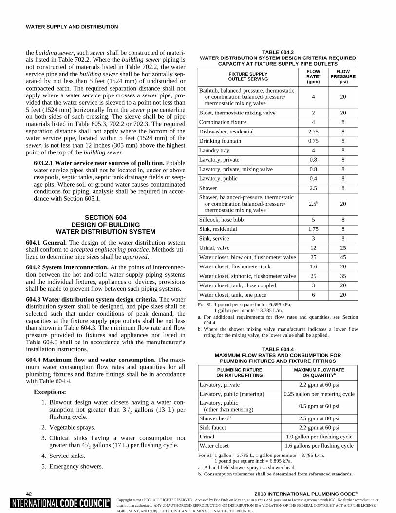
WATER SUPPLY AND DISTRIBUTION
42 2018 INTERNATIONAL PLUMBING CODE®
the building sewer, such sewer shall be constructed of materi-als listed in Table 702.2. Where the building sewer piping isnot constructed of materials listed in Table 702.2, the waterservice pipe and the building sewer shall be horizontally sep-arated by not less than 5 feet (1524 mm) of undisturbed orcompacted earth. The required separation distance shall notapply where a water service pipe crosses a sewer pipe, pro-vided that the water service is sleeved to a point not less than5 feet (1524 mm) horizontally from the sewer pipe centerlineon both sides of such crossing. The sleeve shall be of pipematerials listed in Table 605.3, 702.2 or 702.3. The requiredseparation distance shall not apply where the bottom of thewater service pipe, located within 5 feet (1524 mm) of thesewer, is not less than 12 inches (305 mm) above the highestpoint of the top of the building sewer.
603.2.1 Water service near sources of pollution. Potablewater service pipes shall not be located in, under or abovecesspools, septic tanks, septic tank drainage fields or seep-age pits. Where soil or ground water causes contaminatedconditions for piping, analysis shall be required in accor-dance with Section 605.1.
SECTION 604DESIGN OF BUILDING
WATER DISTRIBUTION SYSTEM
604.1 General. The design of the water distribution systemshall conform to accepted engineering practice. Methods uti-lized to determine pipe sizes shall be approved.
604.2 System interconnection. At the points of interconnec-tion between the hot and cold water supply piping systemsand the individual fixtures, appliances or devices, provisionsshall be made to prevent flow between such piping systems.
604.3 Water distribution system design criteria. The waterdistribution system shall be designed, and pipe sizes shall beselected such that under conditions of peak demand, thecapacities at the fixture supply pipe outlets shall be not lessthan shown in Table 604.3. The minimum flow rate and flowpressure provided to fixtures and appliances not listed inTable 604.3 shall be in accordance with the manufacturer’sinstallation instructions.
604.4 Maximum flow and water consumption. The maxi-mum water consumption flow rates and quantities for allplumbing fixtures and fixture fittings shall be in accordancewith Table 604.4.
Exceptions:
1. Blowout design water closets having a water con-sumption not greater than 31/2 gallons (13 L) perflushing cycle.
2. Vegetable sprays.
3. Clinical sinks having a water consumption notgreater than 41/2 gallons (17 L) per flushing cycle.
4. Service sinks.
5. Emergency showers.
TABLE 604.4MAXIMUM FLOW RATES AND CONSUMPTION FOR
PLUMBING FIXTURES AND FIXTURE FITTINGS
For SI: 1 gallon = 3.785 L, 1 gallon per minute = 3.785 L/m, 1 pound per square inch = 6.895 kPa.
a. A hand-held shower spray is a shower head. b. Consumption tolerances shall be determined from referenced standards.
PLUMBING FIXTURE OR FIXTURE FITTING
MAXIMUM FLOW RATE OR QUANTITYb
Lavatory, private 2.2 gpm at 60 psi
Lavatory, public (metering) 0.25 gallon per metering cycle
Lavatory, public (other than metering)
0.5 gpm at 60 psi
Shower heada 2.5 gpm at 80 psi
Sink faucet 2.2 gpm at 60 psi
Urinal 1.0 gallon per flushing cycle
Water closet 1.6 gallons per flushing cycle
TABLE 604.3WATER DISTRIBUTION SYSTEM DESIGN CRITERIA REQUIRED
CAPACITY AT FIXTURE SUPPLY PIPE OUTLETS
For SI: 1 pound per square inch = 6.895 kPa, 1 gallon per minute = 3.785 L/m.
a. For additional requirements for flow rates and quantities, see Section604.4.
b. Where the shower mixing valve manufacturer indicates a lower flowrating for the mixing valve, the lower value shall be applied.
FIXTURE SUPPLY OUTLET SERVING
FLOW RATEa
(gpm)
FLOW PRESSURE
(psi)
Bathtub, balanced-pressure, thermostaticor combination balanced-pressure/thermostatic mixing valve
4 20
Bidet, thermostatic mixing valve 2 20
Combination fixture 4 8
Dishwasher, residential 2.75 8
Drinking fountain 0.75 8
Laundry tray 4 8
Lavatory, private 0.8 8
Lavatory, private, mixing valve 0.8 8
Lavatory, public 0.4 8
Shower 2.5 8
Shower, balanced-pressure, thermostaticor combination balanced-pressure/thermostatic mixing valve
2.5b 20
Sillcock, hose bibb 5 8
Sink, residential 1.75 8
Sink, service 3 8
Urinal, valve 12 25
Water closet, blow out, flushometer valve 25 45
Water closet, flushometer tank 1.6 20
Water closet, siphonic, flushometer valve 25 35
Water closet, tank, close coupled 3 20
Water closet, tank, one piece 6 20
Copyright © 2017 ICC. ALL RIGHTS RESERVED. Accessed by Eric Fitch on May 15, 2018 8:17:14 AM pursuant to License Agreement with ICC. No further reproduction ordistribution authorized. ANY UNAUTHORIZED REPRODUCTION OR DISTRIBUTION IS A VIOLATION OF THE FEDERAL COPYRIGHT ACT AND THE LICENSEAGREEMENT, AND SUBJECT TO CIVIL AND CRIMINAL PENALTIES THEREUNDER.
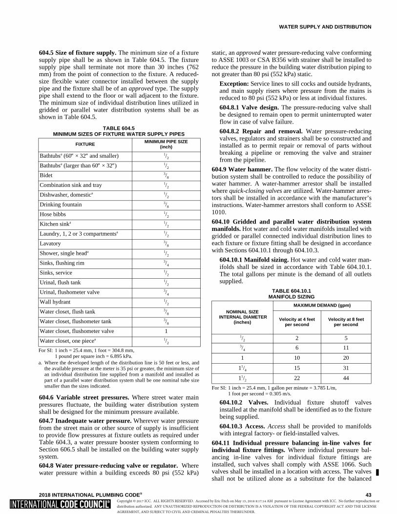
WATER SUPPLY AND DISTRIBUTION
2018 INTERNATIONAL PLUMBING CODE® 43
604.5 Size of fixture supply. The minimum size of a fixturesupply pipe shall be as shown in Table 604.5. The fixturesupply pipe shall terminate not more than 30 inches (762mm) from the point of connection to the fixture. A reduced-size flexible water connector installed between the supplypipe and the fixture shall be of an approved type. The supplypipe shall extend to the floor or wall adjacent to the fixture.The minimum size of individual distribution lines utilized ingridded or parallel water distribution systems shall be asshown in Table 604.5.
604.6 Variable street pressures. Where street water mainpressures fluctuate, the building water distribution systemshall be designed for the minimum pressure available.
604.7 Inadequate water pressure. Wherever water pressurefrom the street main or other source of supply is insufficientto provide flow pressures at fixture outlets as required underTable 604.3, a water pressure booster system conforming toSection 606.5 shall be installed on the building water supplysystem.
604.8 Water pressure-reducing valve or regulator. Wherewater pressure within a building exceeds 80 psi (552 kPa)
static, an approved water pressure-reducing valve conformingto ASSE 1003 or CSA B356 with strainer shall be installed toreduce the pressure in the building water distribution piping tonot greater than 80 psi (552 kPa) static.
Exception: Service lines to sill cocks and outside hydrants,and main supply risers where pressure from the mains isreduced to 80 psi (552 kPa) or less at individual fixtures.
604.8.1 Valve design. The pressure-reducing valve shallbe designed to remain open to permit uninterrupted waterflow in case of valve failure.
604.8.2 Repair and removal. Water pressure-reducingvalves, regulators and strainers shall be so constructed andinstalled as to permit repair or removal of parts withoutbreaking a pipeline or removing the valve and strainerfrom the pipeline.
604.9 Water hammer. The flow velocity of the water distri-bution system shall be controlled to reduce the possibility ofwater hammer. A water-hammer arrestor shall be installedwhere quick-closing valves are utilized. Water-hammer arres-tors shall be installed in accordance with the manufacturer’sinstructions. Water-hammer arrestors shall conform to ASSE1010.
604.10 Gridded and parallel water distribution systemmanifolds. Hot water and cold water manifolds installed withgridded or parallel connected individual distribution lines toeach fixture or fixture fitting shall be designed in accordancewith Sections 604.10.1 through 604.10.3.
604.10.1 Manifold sizing. Hot water and cold water man-ifolds shall be sized in accordance with Table 604.10.1.The total gallons per minute is the demand of all outletssupplied.
TABLE 604.10.1MANIFOLD SIZING
For SI: 1 inch = 25.4 mm, 1 gallon per minute = 3.785 L/m, 1 foot per second = 0.305 m/s.
604.10.2 Valves. Individual fixture shutoff valvesinstalled at the manifold shall be identified as to the fixturebeing supplied.
604.10.3 Access. Access shall be provided to manifoldswith integral factory- or field-installed valves.
604.11 Individual pressure balancing in-line valves forindividual fixture fittings. Where individual pressure bal-ancing in-line valves for individual fixture fittings areinstalled, such valves shall comply with ASSE 1066. Suchvalves shall be installed in a location with access. The valvesshall not be utilized alone as a substitute for the balanced
NOMINAL SIZE INTERNAL DIAMETER
(inches)
MAXIMUM DEMAND (gpm)
Velocity at 4 feetper second
Velocity at 8 feetper second
1/2 2 53/4 6 11
1 10 20
11/4 15 31
11/2 22 44
TABLE 604.5MINIMUM SIZES OF FIXTURE WATER SUPPLY PIPES
For SI: 1 inch = 25.4 mm, 1 foot = 304.8 mm, 1 pound per square inch = 6.895 kPa.
a. Where the developed length of the distribution line is 50 feet or less, andthe available pressure at the meter is 35 psi or greater, the minimum size ofan individual distribution line supplied from a manifold and installed aspart of a parallel water distribution system shall be one nominal tube sizesmaller than the sizes indicated.
FIXTURE MINIMUM PIPE SIZE (inch)
Bathtubsa (60″ × 32″ and smaller) 1/2
Bathtubsa (larger than 60″ × 32″) 1/2
Bidet 3/8
Combination sink and tray 1/2
Dishwasher, domestica 1/2
Drinking fountain 3/8
Hose bibbs 1/2
Kitchen sinka 1/2
Laundry, 1, 2 or 3 compartmentsa 1/2
Lavatory 3/8
Shower, single heada 1/2
Sinks, flushing rim 3/4
Sinks, service 1/2
Urinal, flush tank 1/2
Urinal, flushometer valve 3/4
Wall hydrant 1/2
Water closet, flush tank 3/8
Water closet, flushometer tank 3/8
Water closet, flushometer valve 1
Water closet, one piecea 1/2
Copyright © 2017 ICC. ALL RIGHTS RESERVED. Accessed by Eric Fitch on May 15, 2018 8:17:14 AM pursuant to License Agreement with ICC. No further reproduction ordistribution authorized. ANY UNAUTHORIZED REPRODUCTION OR DISTRIBUTION IS A VIOLATION OF THE FEDERAL COPYRIGHT ACT AND THE LICENSEAGREEMENT, AND SUBJECT TO CIVIL AND CRIMINAL PENALTIES THEREUNDER.
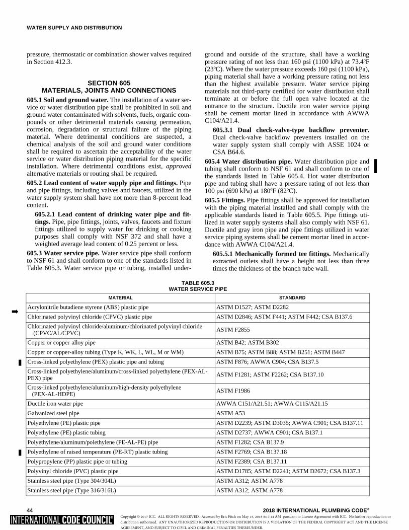
WATER SUPPLY AND DISTRIBUTION
44 2018 INTERNATIONAL PLUMBING CODE®
pressure, thermostatic or combination shower valves requiredin Section 412.3.
SECTION 605MATERIALS, JOINTS AND CONNECTIONS
605.1 Soil and ground water. The installation of a water ser-vice or water distribution pipe shall be prohibited in soil andground water contaminated with solvents, fuels, organic com-pounds or other detrimental materials causing permeation,corrosion, degradation or structural failure of the pipingmaterial. Where detrimental conditions are suspected, achemical analysis of the soil and ground water conditionsshall be required to ascertain the acceptability of the waterservice or water distribution piping material for the specificinstallation. Where detrimental conditions exist, approvedalternative materials or routing shall be required.
605.2 Lead content of water supply pipe and fittings. Pipeand pipe fittings, including valves and faucets, utilized in thewater supply system shall have not more than 8-percent leadcontent.
605.2.1 Lead content of drinking water pipe and fit-tings. Pipe, pipe fittings, joints, valves, faucets and fixturefittings utilized to supply water for drinking or cookingpurposes shall comply with NSF 372 and shall have aweighted average lead content of 0.25 percent or less.
605.3 Water service pipe. Water service pipe shall conformto NSF 61 and shall conform to one of the standards listed inTable 605.3. Water service pipe or tubing, installed under-
ground and outside of the structure, shall have a workingpressure rating of not less than 160 psi (1100 kPa) at 73.4ºF(23ºC). Where the water pressure exceeds 160 psi (1100 kPa),piping material shall have a working pressure rating not lessthan the highest available pressure. Water service pipingmaterials not third-party certified for water distribution shallterminate at or before the full open valve located at theentrance to the structure. Ductile iron water service pipingshall be cement mortar lined in accordance with AWWAC104/A21.4.
605.3.1 Dual check-valve-type backflow preventer.Dual check-valve backflow preventers installed on thewater supply system shall comply with ASSE 1024 orCSA B64.6.
605.4 Water distribution pipe. Water distribution pipe andtubing shall conform to NSF 61 and shall conform to one ofthe standards listed in Table 605.4. Hot water distributionpipe and tubing shall have a pressure rating of not less than100 psi (690 kPa) at 180ºF (82ºC).
605.5 Fittings. Pipe fittings shall be approved for installationwith the piping material installed and shall comply with theapplicable standards listed in Table 605.5. Pipe fittings uti-lized in water supply systems shall also comply with NSF 61.Ductile and gray iron pipe and pipe fittings utilized in waterservice piping systems shall be cement mortar lined in accor-dance with AWWA C104/A21.4.
605.5.1 Mechanically formed tee fittings. Mechanicallyextracted outlets shall have a height not less than threetimes the thickness of the branch tube wall.
TABLE 605.3 WATER SERVICE PIPE
MATERIAL STANDARD
Acrylonitrile butadiene styrene (ABS) plastic pipe ASTM D1527; ASTM D2282
Chlorinated polyvinyl chloride (CPVC) plastic pipe ASTM D2846; ASTM F441; ASTM F442; CSA B137.6
Chlorinated polyvinyl chloride/aluminum/chlorinated polyvinyl chloride (CPVC/AL/CPVC)
ASTM F2855
Copper or copper-alloy pipe ASTM B42; ASTM B302
Copper or copper-alloy tubing (Type K, WK, L, WL, M or WM) ASTM B75; ASTM B88; ASTM B251; ASTM B447
Cross-linked polyethylene (PEX) plastic pipe and tubing ASTM F876; AWWA C904; CSA B137.5
Cross-linked polyethylene/aluminum/cross-linked polyethylene (PEX-AL-PEX) pipe
ASTM F1281; ASTM F2262; CSA B137.10
Cross-linked polyethylene/aluminum/high-density polyethylene (PEX-AL-HDPE)
ASTM F1986
Ductile iron water pipe AWWA C151/A21.51; AWWA C115/A21.15
Galvanized steel pipe ASTM A53
Polyethylene (PE) plastic pipe ASTM D2239; ASTM D3035; AWWA C901; CSA B137.11
Polyethylene (PE) plastic tubing ASTM D2737; AWWA C901; CSA B137.1
Polyethylene/aluminum/polethylene (PE-AL-PE) pipe ASTM F1282; CSA B137.9
Polyethylene of raised temperature (PE-RT) plastic tubing ASTM F2769; CSA B137.18
Polypropylene (PP) plastic pipe or tubing ASTM F2389; CSA B137.11
Polyvinyl chloride (PVC) plastic pipe ASTM D1785; ASTM D2241; ASTM D2672; CSA B137.3
Stainless steel pipe (Type 304/304L) ASTM A312; ASTM A778
Stainless steel pipe (Type 316/316L) ASTM A312; ASTM A778
�
Copyright © 2017 ICC. ALL RIGHTS RESERVED. Accessed by Eric Fitch on May 15, 2018 8:17:14 AM pursuant to License Agreement with ICC. No further reproduction ordistribution authorized. ANY UNAUTHORIZED REPRODUCTION OR DISTRIBUTION IS A VIOLATION OF THE FEDERAL COPYRIGHT ACT AND THE LICENSEAGREEMENT, AND SUBJECT TO CIVIL AND CRIMINAL PENALTIES THEREUNDER.
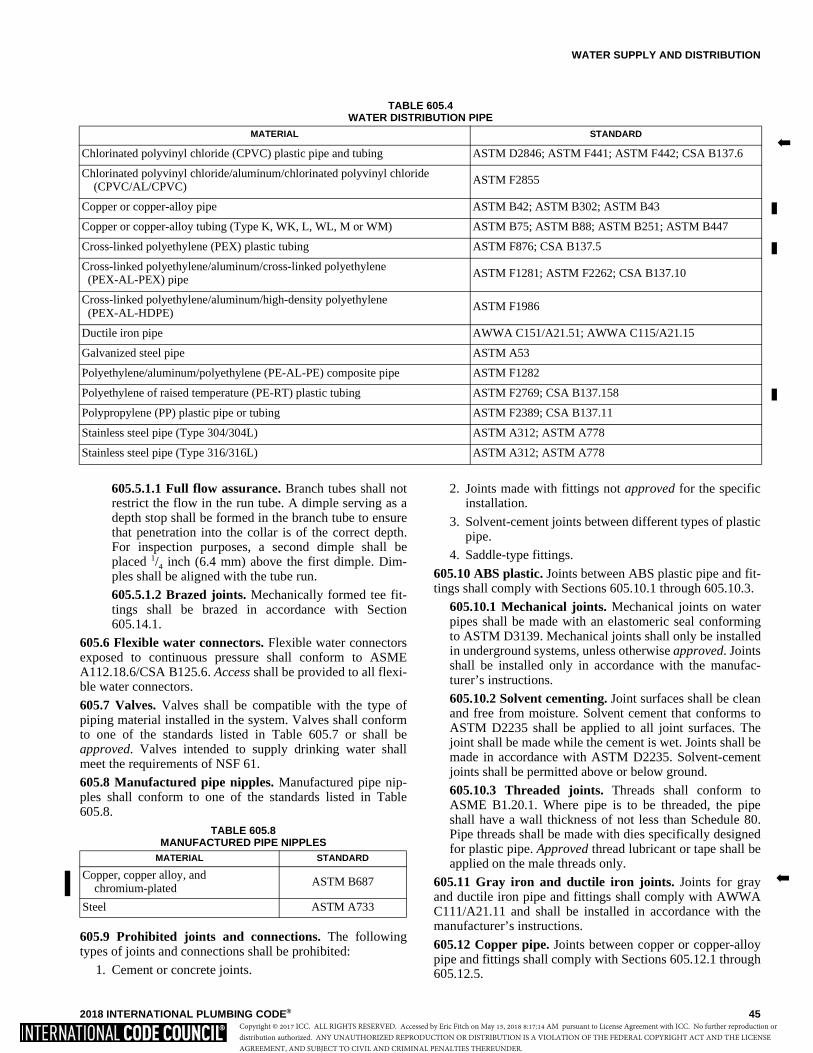
WATER SUPPLY AND DISTRIBUTION
2018 INTERNATIONAL PLUMBING CODE® 45
605.5.1.1 Full flow assurance. Branch tubes shall notrestrict the flow in the run tube. A dimple serving as adepth stop shall be formed in the branch tube to ensurethat penetration into the collar is of the correct depth.For inspection purposes, a second dimple shall beplaced 1/4 inch (6.4 mm) above the first dimple. Dim-ples shall be aligned with the tube run.
605.5.1.2 Brazed joints. Mechanically formed tee fit-tings shall be brazed in accordance with Section605.14.1.
605.6 Flexible water connectors. Flexible water connectorsexposed to continuous pressure shall conform to ASMEA112.18.6/CSA B125.6. Access shall be provided to all flexi-ble water connectors.
605.7 Valves. Valves shall be compatible with the type ofpiping material installed in the system. Valves shall conformto one of the standards listed in Table 605.7 or shall beapproved. Valves intended to supply drinking water shallmeet the requirements of NSF 61.
605.8 Manufactured pipe nipples. Manufactured pipe nip-ples shall conform to one of the standards listed in Table605.8.
TABLE 605.8MANUFACTURED PIPE NIPPLES
605.9 Prohibited joints and connections. The followingtypes of joints and connections shall be prohibited:
1. Cement or concrete joints.
2. Joints made with fittings not approved for the specificinstallation.
3. Solvent-cement joints between different types of plasticpipe.
4. Saddle-type fittings.
605.10 ABS plastic. Joints between ABS plastic pipe and fit-tings shall comply with Sections 605.10.1 through 605.10.3.
605.10.1 Mechanical joints. Mechanical joints on waterpipes shall be made with an elastomeric seal conformingto ASTM D3139. Mechanical joints shall only be installedin underground systems, unless otherwise approved. Jointsshall be installed only in accordance with the manufac-turer’s instructions.
605.10.2 Solvent cementing. Joint surfaces shall be cleanand free from moisture. Solvent cement that conforms toASTM D2235 shall be applied to all joint surfaces. Thejoint shall be made while the cement is wet. Joints shall bemade in accordance with ASTM D2235. Solvent-cementjoints shall be permitted above or below ground.
605.10.3 Threaded joints. Threads shall conform toASME B1.20.1. Where pipe is to be threaded, the pipeshall have a wall thickness of not less than Schedule 80.Pipe threads shall be made with dies specifically designedfor plastic pipe. Approved thread lubricant or tape shall beapplied on the male threads only.
605.11 Gray iron and ductile iron joints. Joints for grayand ductile iron pipe and fittings shall comply with AWWAC111/A21.11 and shall be installed in accordance with themanufacturer’s instructions.
605.12 Copper pipe. Joints between copper or copper-alloypipe and fittings shall comply with Sections 605.12.1 through605.12.5.
MATERIAL STANDARD
Copper, copper alloy, and chromium-plated
ASTM B687
Steel ASTM A733
�
TABLE 605.4WATER DISTRIBUTION PIPE
MATERIAL STANDARD
Chlorinated polyvinyl chloride (CPVC) plastic pipe and tubing ASTM D2846; ASTM F441; ASTM F442; CSA B137.6
Chlorinated polyvinyl chloride/aluminum/chlorinated polyvinyl chloride (CPVC/AL/CPVC)
ASTM F2855
Copper or copper-alloy pipe ASTM B42; ASTM B302; ASTM B43
Copper or copper-alloy tubing (Type K, WK, L, WL, M or WM) ASTM B75; ASTM B88; ASTM B251; ASTM B447
Cross-linked polyethylene (PEX) plastic tubing ASTM F876; CSA B137.5
Cross-linked polyethylene/aluminum/cross-linked polyethylene (PEX-AL-PEX) pipe ASTM F1281; ASTM F2262; CSA B137.10
Cross-linked polyethylene/aluminum/high-density polyethylene (PEX-AL-HDPE)
ASTM F1986
Ductile iron pipe AWWA C151/A21.51; AWWA C115/A21.15
Galvanized steel pipe ASTM A53
Polyethylene/aluminum/polyethylene (PE-AL-PE) composite pipe ASTM F1282
Polyethylene of raised temperature (PE-RT) plastic tubing ASTM F2769; CSA B137.158
Polypropylene (PP) plastic pipe or tubing ASTM F2389; CSA B137.11
Stainless steel pipe (Type 304/304L) ASTM A312; ASTM A778
Stainless steel pipe (Type 316/316L) ASTM A312; ASTM A778
�
Copyright © 2017 ICC. ALL RIGHTS RESERVED. Accessed by Eric Fitch on May 15, 2018 8:17:14 AM pursuant to License Agreement with ICC. No further reproduction ordistribution authorized. ANY UNAUTHORIZED REPRODUCTION OR DISTRIBUTION IS A VIOLATION OF THE FEDERAL COPYRIGHT ACT AND THE LICENSEAGREEMENT, AND SUBJECT TO CIVIL AND CRIMINAL PENALTIES THEREUNDER.
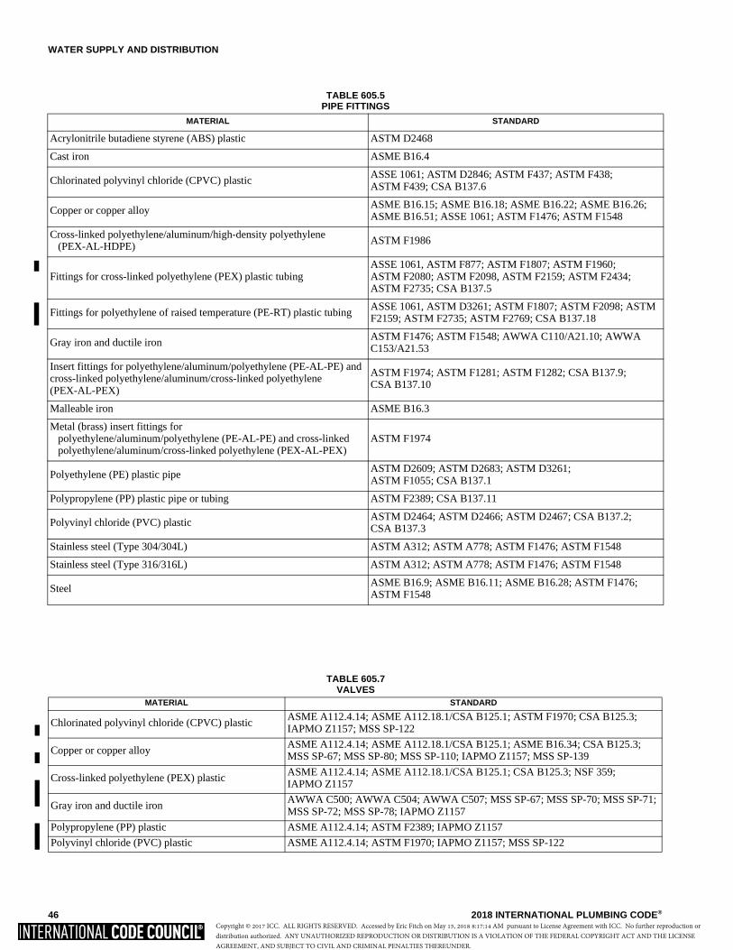
WATER SUPPLY AND DISTRIBUTION
46 2018 INTERNATIONAL PLUMBING CODE®
TABLE 605.5PIPE FITTINGS
MATERIAL STANDARD
Acrylonitrile butadiene styrene (ABS) plastic ASTM D2468
Cast iron ASME B16.4
Chlorinated polyvinyl chloride (CPVC) plastic ASSE 1061; ASTM D2846; ASTM F437; ASTM F438; ASTM F439; CSA B137.6
Copper or copper alloy ASME B16.15; ASME B16.18; ASME B16.22; ASME B16.26; ASME B16.51; ASSE 1061; ASTM F1476; ASTM F1548
Cross-linked polyethylene/aluminum/high-density polyethylene (PEX-AL-HDPE) ASTM F1986
Fittings for cross-linked polyethylene (PEX) plastic tubingASSE 1061, ASTM F877; ASTM F1807; ASTM F1960; ASTM F2080; ASTM F2098, ASTM F2159; ASTM F2434; ASTM F2735; CSA B137.5
Fittings for polyethylene of raised temperature (PE-RT) plastic tubingASSE 1061, ASTM D3261; ASTM F1807; ASTM F2098; ASTM F2159; ASTM F2735; ASTM F2769; CSA B137.18
Gray iron and ductile iron ASTM F1476; ASTM F1548; AWWA C110/A21.10; AWWA C153/A21.53
Insert fittings for polyethylene/aluminum/polyethylene (PE-AL-PE) and cross-linked polyethylene/aluminum/cross-linked polyethylene(PEX-AL-PEX)
ASTM F1974; ASTM F1281; ASTM F1282; CSA B137.9; CSA B137.10
Malleable iron ASME B16.3
Metal (brass) insert fittings for polyethylene/aluminum/polyethylene (PE-AL-PE) and cross-linked polyethylene/aluminum/cross-linked polyethylene (PEX-AL-PEX)
ASTM F1974
Polyethylene (PE) plastic pipe ASTM D2609; ASTM D2683; ASTM D3261;ASTM F1055; CSA B137.1
Polypropylene (PP) plastic pipe or tubing ASTM F2389; CSA B137.11
Polyvinyl chloride (PVC) plastic ASTM D2464; ASTM D2466; ASTM D2467; CSA B137.2; CSA B137.3
Stainless steel (Type 304/304L) ASTM A312; ASTM A778; ASTM F1476; ASTM F1548
Stainless steel (Type 316/316L) ASTM A312; ASTM A778; ASTM F1476; ASTM F1548
Steel ASME B16.9; ASME B16.11; ASME B16.28; ASTM F1476; ASTM F1548
TABLE 605.7VALVES
MATERIAL STANDARD
Chlorinated polyvinyl chloride (CPVC) plasticASME A112.4.14; ASME A112.18.1/CSA B125.1; ASTM F1970; CSA B125.3; IAPMO Z1157; MSS SP-122
Copper or copper alloyASME A112.4.14; ASME A112.18.1/CSA B125.1; ASME B16.34; CSA B125.3; MSS SP-67; MSS SP-80; MSS SP-110; IAPMO Z1157; MSS SP-139
Cross-linked polyethylene (PEX) plastic ASME A112.4.14; ASME A112.18.1/CSA B125.1; CSA B125.3; NSF 359;IAPMO Z1157
Gray iron and ductile ironAWWA C500; AWWA C504; AWWA C507; MSS SP-67; MSS SP-70; MSS SP-71; MSS SP-72; MSS SP-78; IAPMO Z1157
Polypropylene (PP) plastic ASME A112.4.14; ASTM F2389; IAPMO Z1157
Polyvinyl chloride (PVC) plastic ASME A112.4.14; ASTM F1970; IAPMO Z1157; MSS SP-122
Copyright © 2017 ICC. ALL RIGHTS RESERVED. Accessed by Eric Fitch on May 15, 2018 8:17:14 AM pursuant to License Agreement with ICC. No further reproduction ordistribution authorized. ANY UNAUTHORIZED REPRODUCTION OR DISTRIBUTION IS A VIOLATION OF THE FEDERAL COPYRIGHT ACT AND THE LICENSEAGREEMENT, AND SUBJECT TO CIVIL AND CRIMINAL PENALTIES THEREUNDER.
WATER SUPPLY AND DISTRIBUTION
2018 INTERNATIONAL PLUMBING CODE® 47
605.12.1 Brazed joints. Joint surfaces shall be cleaned.An approved flux shall be applied where required. Thejoint shall be brazed with a filler metal conforming toAWS A5.8.
605.12.2 Mechanical joints. Mechanical joints shall beinstalled in accordance with the manufacturer’s instruc-tions.
605.12.3 Solder joints. Solder joints shall be made inaccordance with ASTM B828. Cut tube ends shall bereamed to the full inside diameter of the tube end. Jointsurfaces shall be cleaned. A flux conforming to ASTMB813 shall be applied. The joint shall be soldered with asolder conforming to ASTM B32. The joining of watersupply piping shall be made with lead-free solder andfluxes. “Lead free” shall mean a chemical compositionequal to or less than 0.2-percent lead.
605.12.4 Threaded joints. Threads shall conform toASME B1.20.1. Pipe-joint compound or tape shall beapplied on the male threads only.
605.12.5 Welded joints. Joint surfaces shall be cleaned.The joint shall be welded with an approved filler metal.
605.13 Copper tubing. Joints between copper or copper-alloy tubing and fittings shall comply with Sections 605.13.1through 605.13.7.
605.13.1 Brazed joints. Joint surfaces shall be cleaned.An approved flux shall be applied where required. Thejoint shall be brazed with a filler metal conforming toAWS A5.8.
605.13.2 Flared joints. Flared joints for water pipe shallbe made by a tool designed for that operation.
605.13.3 Grooved and shouldered mechanical joints.Grooved and shouldered mechanical joints shall complywith ASTM F1476, shall be made with an approved elas-tomeric seal and shall be installed in accordance with themanufacturer’s instructions. Such joints shall be exposedor concealed.
605.13.4 Mechanical joints. Mechanical joints shall beinstalled in accordance with the manufacturer’s instruc-tions.
605.13.5 Press-connect joints. Press-connect joints shallconform to one of the standards indicated in Table 605.5,and shall be installed in accordance with the manufac-turer’s instructions. Cut tube ends shall be reamed to thefull inside diameter of the tube end. Joint surfaces shall becleaned. The tube shall be fully inserted into the press-connect fitting. Press-connect joints shall be pressed witha tool certified by the manufacturer.
605.13.6 Solder joints. Solder joints shall be made inaccordance with the methods of ASTM B828. Cut tubeends shall be reamed to the full inside diameter of the tubeend. Joint surfaces shall be cleaned. A flux conforming toASTM B813 shall be applied. The joint shall be solderedwith a solder conforming to ASTM B32. The joining ofwater supply piping shall be made with lead-free solderand flux. “Lead free” shall mean a chemical compositionequal to or less than 0.2-percent lead.
605.13.7 Push-fit joints. Push-fit joints shall conform toASSE 1061 and shall be installed in accordance with themanufacturer’s instructions.
605.14 CPVC plastic. Joints between CPVC plastic pipe andfittings shall comply with Sections 605.14.1 through605.14.4.
605.14.1 Mechanical joints. Mechanical joints shall beinstalled in accordance with the manufacturer’s instruc-tions.
605.14.2 Solvent cementing. Joint surfaces shall be cleanand free from moisture. Joints shall be made in accordancewith the pipe manufacturer’s installation instructions.Where such instructions require that a primer be used, theprimer shall be applied to the joint surfaces and a solventcement orange in color and conforming to ASTM F493shall be applied to the joint surfaces. Where such instruc-tions allow for a one-step solvent cement, yellow in colorand conforming to ASTM F493, to be used, the joint sur-faces shall not require application of a primer before thesolvent cement is applied. The joint shall be made whilethe cement is wet and in accordance with ASTM D2846 orASTM F493. Solvent cemented joints shall be permittedabove or below ground.
605.14.3 Threaded joints. Threads shall conform toASME B1.20.1. Where pipe is to be threaded, the pipeshall have a wall thickness of not less than Schedule 80.Pipe threads shall be made with dies specifically designedfor plastic pipe. The pressure rating of threaded pipe shallbe reduced by 50 percent. Thread-by-socket molded fit-tings shall be permitted. Approved thread lubricant or tapeshall be applied on the male threads only.
605.14.4 Push-fit joints. Push-fit joints shall conform toASSE 1061 and shall be installed in accordance with themanufacturer’s instructions.
605.15 Chlorinated polyvinyl chloride/aluminum/chlori-nated polyvinyl chloride (CPVC/AL/CPVC) pipe and tub-ing. Joints between CPVC/AL/CPVC plastic pipe or CPVCfittings shall comply with Sections 605.15.1 and 605.15.2.
605.15.1 Mechanical joints. Mechanical joints shall beinstalled in accordance with the manufacturer’s instruc-tions.
605.15.2 Solvent cementing. Joint surfaces shall beclean and free from moisture, and an approved primershall be applied. Solvent cement, orange in color andconforming to ASTM F493, shall be applied to jointsurfaces. The joint shall be made while the cement iswet, and in accordance with ASTM D2846 or ASTMF493. Solvent cement joints shall be permitted above orbelow ground.
Exception: A primer is not required where all of thefollowing conditions apply:
1. The solvent cement used is third-party certi-fied as conforming to ASTM F493.
2. The solvent cement used is yellow in color.
3. The solvent cement is used only for joining 1/2-inch (12.7 mm) through 2-inch-diameter (51
Copyright © 2017 ICC. ALL RIGHTS RESERVED. Accessed by Eric Fitch on May 15, 2018 8:17:14 AM pursuant to License Agreement with ICC. No further reproduction ordistribution authorized. ANY UNAUTHORIZED REPRODUCTION OR DISTRIBUTION IS A VIOLATION OF THE FEDERAL COPYRIGHT ACT AND THE LICENSEAGREEMENT, AND SUBJECT TO CIVIL AND CRIMINAL PENALTIES THEREUNDER.
WATER SUPPLY AND DISTRIBUTION
48 2018 INTERNATIONAL PLUMBING CODE®
mm) CPVC/AL/CPVC pipe and CPVC fit-tings.
4. The CPVC fittings are manufactured in accor-dance with ASTM D2846.
605.16 PEX plastic. Joints between cross-linked polyeth-ylene plastic tubing and fittings shall comply with Sections605.16.1 through 605.16.3.
605.16.1 Flared joints. Flared pipe ends shall be made bya tool designed for that operation.
605.16.2 Mechanical joints. Mechanical joints shall beinstalled in accordance with the manufacturer’s instruc-tions. Fittings for cross-linked polyethylene (PEX) plastictubing shall comply with the applicable standards listed inTable 605.5 and shall be installed in accordance with themanufacturer’s instructions. PEX tubing shall be factorymarked with the appropriate standards for the fittings thatthe PEX manufacturer specifies for use with the tubing.
605.16.3 Push-fit joints. Push-fit joints shall conform toASSE 1061 and shall be installed in accordance with themanufacturer’s instructions.
605.17 Steel. Joints between galvanized steel pipe and fit-tings shall comply with Sections 605.17.1 through 605.17.3.
605.17.1 Threaded joints. Threads shall conform toASME B1.20.1. Pipe-joint compound or tape shall beapplied on the male threads only.
605.17.2 Mechanical joints. Joints shall be made with anapproved elastomeric seal. Mechanical joints shall beinstalled in accordance with the manufacturer’s instruc-tions.
605.17.3 Grooved and shouldered mechanical joints.Grooved and shouldered mechanical joints shall complywith ASTM F1476, shall be made with an approved elas-tomeric seal and shall be installed in accordance with themanufacturer’s instructions. Such joints shall be exposedor concealed.
605.18 PE plastic. Joints between polyethylene plastic pipeor tubing and fittings shall comply with Sections 605.18.1through 605.18.4.
605.18.1 Flared joints. Flared joints shall be permittedwhere so indicated by the pipe manufacturer. Flared jointsshall be made by a tool designed for that operation.
605.18.2 Heat-fusion joints. Joint surfaces shall be cleanand free from moisture. Joint surfaces shall be heated tomelt temperature and joined. The joint shall be undis-turbed until cool. Joints shall be made in accordance withASTM D2657.
605.18.3 Mechanical joints. Mechanical joints shall beinstalled in accordance with the manufacturer’s instruc-tions.
605.18.4 Installation. Polyethylene pipe shall be cutsquare, with a cutter designed for plastic pipe. Exceptwhere joined by heat fusion, pipe ends shall be chamferedto remove sharp edges. Kinked pipe shall not be installed.The minimum pipe bending radius shall be not less than30 pipe diameters, or the minimum coil radius, whichever
is greater. Piping shall not be bent beyond straightening ofthe curvature of the coil. Bends shall be prohibited within10 pipe diameters of any fitting or valve. Stiffener insertsinstalled with compression-type couplings and fittingsshall not extend beyond the clamp or nut of the couplingor fitting.
605.19 Polypropylene (PP) plastic. Joints between PP plas-tic pipe and fittings shall comply with Section 605.19.1 or605.19.2.
605.19.1 Heat-fusion joints. Heat-fusion joints for poly-propylene pipe and tubing joints shall be installed withsocket-type heat-fused polypropylene fittings, butt-fusionpolypropylene fittings or electrofusion polypropylene fit-tings. Joint surfaces shall be clean and free from moisture.The joint shall be undisturbed until cool. Joints shall bemade in accordance with ASTM F2389.
605.19.2 Mechanical and compression sleeve joints.Mechanical and compression sleeve joints shall beinstalled in accordance with the manufacturer’s instruc-tions.
605.20 Polyethylene/aluminum/polyethylene (PE-AL-PE)and cross-linked polyethylene/aluminum/cross-linkedpolyethylene (PEX-AL-PEX). Joints between PE-AL-PE orPEX-AL-PEX pipe and fittings shall comply with Section605.20.1.
605.20.1 Mechanical joints. Mechanical joints shall beinstalled in accordance with the manufacturer’s instruc-tions. Fittings for PE-AL-PE and PEX-AL-PEX asdescribed in ASTM F1974, ASTM F1281, ASTM F1282,CSA B137.9 and CSA B137.10 shall be installed in accor-dance with the manufacturer’s instructions.
605.21 PVC plastic. Joints between PVC plastic pipe and fit-tings shall comply with Sections 605.21.1 through 605.21.3.
605.21.1 Mechanical joints. Mechanical joints on waterpipe shall be made with an elastomeric seal conforming toASTM D3139. Mechanical joints shall not be installed inabove-ground systems unless otherwise approved. Jointsshall be installed in accordance with the manufacturer’sinstructions.
605.21.2 Grooved and shouldered mechanical joints.Grooved and shouldered mechanical joints shall complywith ASTM F1476, shall be made with an approved elas-tomeric seal and shall be installed in accordance with themanufacturer’s instructions. Such joints shall be exposedor concealed.
605.21.3 Solvent cementing. Joint surfaces shall be cleanand free from moisture. A purple primer that conforms toASTM F656 shall be applied. Solvent cement not purplein color and conforming to ASTM D2564 or CSA B137.3shall be applied to all joint surfaces. The joint shall bemade while the cement is wet and shall be in accordancewith ASTM D2855. Solvent-cement joints shall be permit-ted above or below ground.
605.21.4 Threaded joints. Threads shall conform toASME B1.20.1. Where pipe is to be threaded, the pipeshall have a wall thickness of not less than Schedule 80.
Copyright © 2017 ICC. ALL RIGHTS RESERVED. Accessed by Eric Fitch on May 15, 2018 8:17:14 AM pursuant to License Agreement with ICC. No further reproduction ordistribution authorized. ANY UNAUTHORIZED REPRODUCTION OR DISTRIBUTION IS A VIOLATION OF THE FEDERAL COPYRIGHT ACT AND THE LICENSEAGREEMENT, AND SUBJECT TO CIVIL AND CRIMINAL PENALTIES THEREUNDER.
WATER SUPPLY AND DISTRIBUTION
2018 INTERNATIONAL PLUMBING CODE® 49
Pipe threads shall be made with dies specifically designedfor plastic pipe. The pressure rating of threaded pipe shallbe reduced by 50 percent. Thread-by-socket molded fit-tings shall be permitted. Approved thread lubricant or tapeshall be applied on the male threads only.
605.22 Stainless steel. Joints between stainless steel pipe andfittings shall comply with Sections 605.22.1 through605.22.3.
605.22.1 Mechanical joints. Mechanical joints shall beinstalled in accordance with the manufacturer’s instruc-tions.
605.22.2 Welded joints. Joint surfaces shall be cleaned.The joint shall be welded autogenously or with anapproved filler metal as referenced in ASTM A312.
605.22.3 Grooved and shouldered mechanical joints.Grooved and shouldered mechanical joints shall complywith ASTM F1476, shall be made with an approved elas-tomeric seal and shall be installed in accordance with themanufacturer’s instructions. Such joints shall be exposedor concealed.
605.23 Joints between different materials. Joints betweendifferent piping materials shall be made with a mechanicaljoint of the compression or mechanical-sealing type, or shallbe made in accordance with Section 605.23.1, 605.23.2 or605.23.3. Connectors or adapters shall have an elastomericseal conforming to ASTM F477. Joints shall be installed inaccordance with the manufacturer’s instructions.
605.23.1 Copper or copper-alloy tubing to galvanizedsteel pipe. Joints between copper pipe or tubing and gal-vanized steel pipe shall be made with a copper-alloy ordielectric fitting or a dielectric union conforming to ASSE1079. The copper tubing shall be soldered to the fitting inan approved manner, and the fitting shall be screwed tothe threaded pipe.
605.23.2 Plastic pipe or tubing to other piping material.Joints between different types of plastic pipe or betweenplastic pipe and other piping material shall be made withapproved adapters or transition fittings.
605.23.3 Stainless steel. Joints between stainless steel anddifferent piping materials shall be made with a mechanicaljoint of the compression or mechanical sealing type or adielectric fitting or a dielectric union conforming to ASSE1079.
605.24 PE-RT plastic. Joints between polyethylene of raisedtemperature plastic tubing and fittings shall be in accordancewith Section 605.24.1.
605.24.1 Mechanical joints. Mechanical joints shall beinstalled in accordance with the manufacturer’s instruc-tions. Fittings for polyethylene of raised temperature plas-tic tubing shall comply with the applicable standardsindicated in Table 605.5 and shall be installed in accor-dance with the manufacturer’s instructions. Polyethyleneof raised temperature plastic tubing shall be factorymarked with the applicable standards for the fittings thatthe manufacturer of the tubing specifies for use with thetubing.
SECTION 606INSTALLATION OF THE BUILDING WATER DISTRIBUTION SYSTEM
606.1 Location of full-open valves. Full-open valves shallbe installed in the following locations:
1. On the building water service pipe from the publicwater supply near the curb.
2. On the water distribution supply pipe at the entranceinto the structure.
3. On the discharge side of every water meter.
4. On the base of every water riser pipe in occupanciesother than multiple-family residential occupancies thatare two stories or less in height and in one- and two-family residential occupancies.
5. On the top of every water down-feed pipe in occupan-cies other than one- and two-family residential occu-pancies.
6. On the entrance to every water supply pipe to a dwell-ing unit, except where supplying a single fixtureequipped with individual stops.
7. On the water supply pipe to a gravity or pressurizedwater tank.
8. On the water supply pipe to every water heater.
606.2 Location of shutoff valves. Shutoff valves shall beinstalled in the following locations:
1. On the fixture supply to each plumbing fixture otherthan bathtubs and showers in one- and two-family resi-dential occupancies, and other than in individual sleep-ing units that are provided with unit shutoff valves inhotels, motels, boarding houses and similar occupan-cies.
2. On the water supply pipe to each sillcock.
3. On the water supply pipe to each appliance or mechani-cal equipment.
606.3 Access to valves. Access shall be provided to all full-open valves and shutoff valves.
606.4 Valve identification. Service and hose bibb valvesshall be identified. Other valves installed in locations that arenot adjacent to the fixture or appliance shall be identified,indicating the fixture or appliance served.
606.5 Water pressure booster systems. Water pressurebooster systems shall be provided as required by Sections606.5.1 through 606.5.10.
606.5.1 Water pressure booster systems required.Where the water pressure in the public water main or indi-vidual water supply system is insufficient to supply theminimum pressures and quantities specified in this code,the supply shall be supplemented by an elevated watertank, a hydropneumatic pressure booster system or a waterpressure booster pump installed in accordance with Sec-tion 606.5.5.
606.5.2 Support. Water supply tanks shall be supported inaccordance with the International Building Code.
Copyright © 2017 ICC. ALL RIGHTS RESERVED. Accessed by Eric Fitch on May 15, 2018 8:17:14 AM pursuant to License Agreement with ICC. No further reproduction ordistribution authorized. ANY UNAUTHORIZED REPRODUCTION OR DISTRIBUTION IS A VIOLATION OF THE FEDERAL COPYRIGHT ACT AND THE LICENSEAGREEMENT, AND SUBJECT TO CIVIL AND CRIMINAL PENALTIES THEREUNDER.
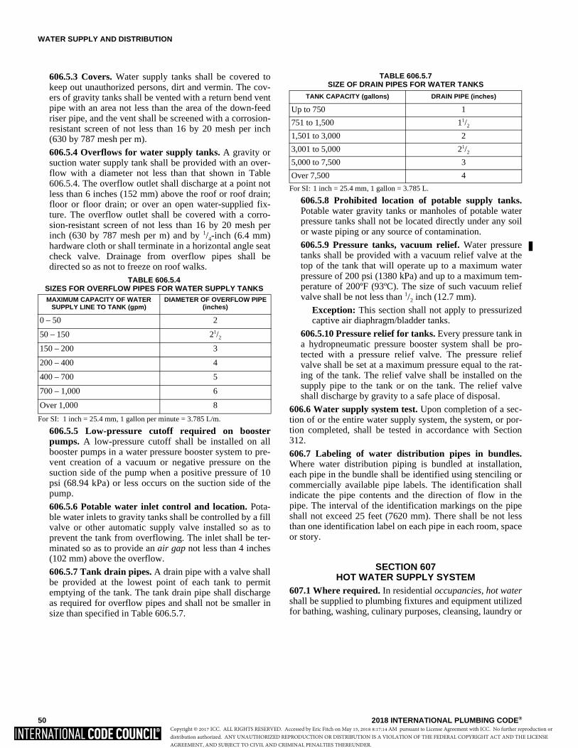
WATER SUPPLY AND DISTRIBUTION
50 2018 INTERNATIONAL PLUMBING CODE®
606.5.3 Covers. Water supply tanks shall be covered tokeep out unauthorized persons, dirt and vermin. The cov-ers of gravity tanks shall be vented with a return bend ventpipe with an area not less than the area of the down-feedriser pipe, and the vent shall be screened with a corrosion-resistant screen of not less than 16 by 20 mesh per inch(630 by 787 mesh per m).
606.5.4 Overflows for water supply tanks. A gravity orsuction water supply tank shall be provided with an over-flow with a diameter not less than that shown in Table606.5.4. The overflow outlet shall discharge at a point notless than 6 inches (152 mm) above the roof or roof drain;floor or floor drain; or over an open water-supplied fix-ture. The overflow outlet shall be covered with a corro-sion-resistant screen of not less than 16 by 20 mesh perinch (630 by 787 mesh per m) and by 1/4-inch (6.4 mm)hardware cloth or shall terminate in a horizontal angle seatcheck valve. Drainage from overflow pipes shall bedirected so as not to freeze on roof walks.
TABLE 606.5.4 SIZES FOR OVERFLOW PIPES FOR WATER SUPPLY TANKS
For SI: 1 inch = 25.4 mm, 1 gallon per minute = 3.785 L/m.
606.5.5 Low-pressure cutoff required on boosterpumps. A low-pressure cutoff shall be installed on allbooster pumps in a water pressure booster system to pre-vent creation of a vacuum or negative pressure on thesuction side of the pump when a positive pressure of 10psi (68.94 kPa) or less occurs on the suction side of thepump.
606.5.6 Potable water inlet control and location. Pota-ble water inlets to gravity tanks shall be controlled by a fillvalve or other automatic supply valve installed so as toprevent the tank from overflowing. The inlet shall be ter-minated so as to provide an air gap not less than 4 inches(102 mm) above the overflow.
606.5.7 Tank drain pipes. A drain pipe with a valve shallbe provided at the lowest point of each tank to permitemptying of the tank. The tank drain pipe shall dischargeas required for overflow pipes and shall not be smaller insize than specified in Table 606.5.7.
TABLE 606.5.7SIZE OF DRAIN PIPES FOR WATER TANKS
For SI: 1 inch = 25.4 mm, 1 gallon = 3.785 L.
606.5.8 Prohibited location of potable supply tanks.Potable water gravity tanks or manholes of potable waterpressure tanks shall not be located directly under any soilor waste piping or any source of contamination.
606.5.9 Pressure tanks, vacuum relief. Water pressuretanks shall be provided with a vacuum relief valve at thetop of the tank that will operate up to a maximum waterpressure of 200 psi (1380 kPa) and up to a maximum tem-perature of 200ºF (93ºC). The size of such vacuum reliefvalve shall be not less than 1/2 inch (12.7 mm).
Exception: This section shall not apply to pressurizedcaptive air diaphragm/bladder tanks.
606.5.10 Pressure relief for tanks. Every pressure tank ina hydropneumatic pressure booster system shall be pro-tected with a pressure relief valve. The pressure reliefvalve shall be set at a maximum pressure equal to the rat-ing of the tank. The relief valve shall be installed on thesupply pipe to the tank or on the tank. The relief valveshall discharge by gravity to a safe place of disposal.
606.6 Water supply system test. Upon completion of a sec-tion of or the entire water supply system, the system, or por-tion completed, shall be tested in accordance with Section312.
606.7 Labeling of water distribution pipes in bundles.Where water distribution piping is bundled at installation,each pipe in the bundle shall be identified using stenciling orcommercially available pipe labels. The identification shallindicate the pipe contents and the direction of flow in thepipe. The interval of the identification markings on the pipeshall not exceed 25 feet (7620 mm). There shall be not lessthan one identification label on each pipe in each room, spaceor story.
SECTION 607HOT WATER SUPPLY SYSTEM
607.1 Where required. In residential occupancies, hot watershall be supplied to plumbing fixtures and equipment utilizedfor bathing, washing, culinary purposes, cleansing, laundry or
MAXIMUM CAPACITY OF WATER SUPPLY LINE TO TANK (gpm)
DIAMETER OF OVERFLOW PIPE (inches)
0 – 50 2
50 – 150 21/2
150 – 200 3
200 – 400 4
400 – 700 5
700 – 1,000 6
Over 1,000 8
TANK CAPACITY (gallons) DRAIN PIPE (inches)
Up to 750 1
751 to 1,500 11/2
1,501 to 3,000 2
3,001 to 5,000 21/2
5,000 to 7,500 3
Over 7,500 4
Copyright © 2017 ICC. ALL RIGHTS RESERVED. Accessed by Eric Fitch on May 15, 2018 8:17:14 AM pursuant to License Agreement with ICC. No further reproduction ordistribution authorized. ANY UNAUTHORIZED REPRODUCTION OR DISTRIBUTION IS A VIOLATION OF THE FEDERAL COPYRIGHT ACT AND THE LICENSEAGREEMENT, AND SUBJECT TO CIVIL AND CRIMINAL PENALTIES THEREUNDER.
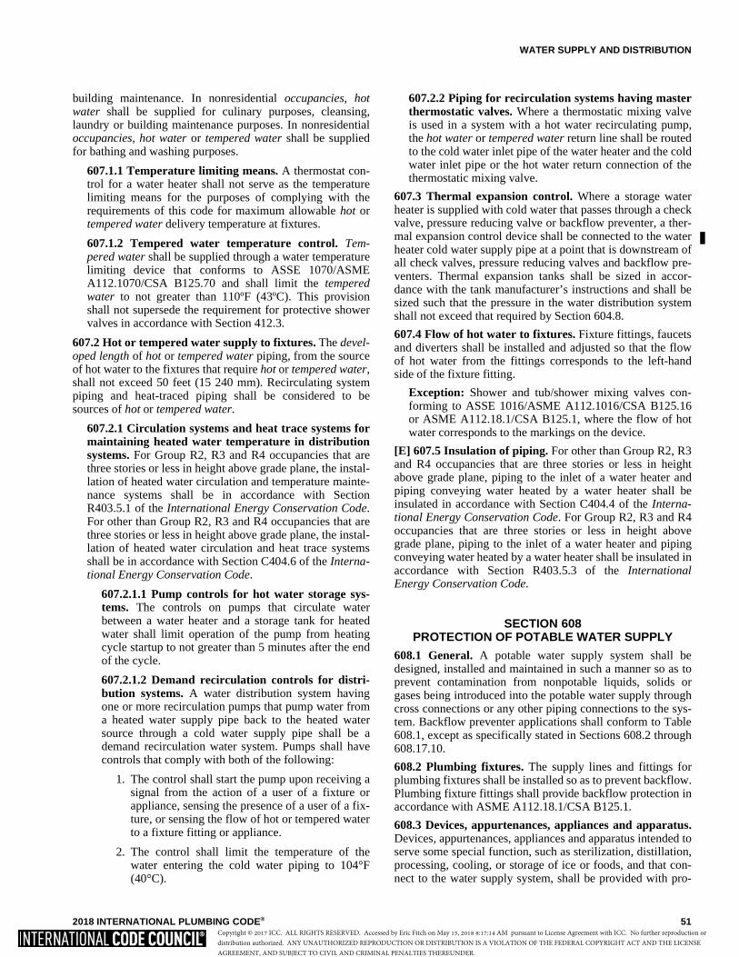
WATER SUPPLY AND DISTRIBUTION
2018 INTERNATIONAL PLUMBING CODE® 51
building maintenance. In nonresidential occupancies, hotwater shall be supplied for culinary purposes, cleansing,laundry or building maintenance purposes. In nonresidentialoccupancies, hot water or tempered water shall be suppliedfor bathing and washing purposes.
607.1.1 Temperature limiting means. A thermostat con-trol for a water heater shall not serve as the temperaturelimiting means for the purposes of complying with therequirements of this code for maximum allowable hot ortempered water delivery temperature at fixtures.
607.1.2 Tempered water temperature control. Tem-pered water shall be supplied through a water temperaturelimiting device that conforms to ASSE 1070/ASMEA112.1070/CSA B125.70 and shall limit the temperedwater to not greater than 110ºF (43ºC). This provisionshall not supersede the requirement for protective showervalves in accordance with Section 412.3.
607.2 Hot or tempered water supply to fixtures. The devel-oped length of hot or tempered water piping, from the sourceof hot water to the fixtures that require hot or tempered water,shall not exceed 50 feet (15 240 mm). Recirculating systempiping and heat-traced piping shall be considered to besources of hot or tempered water.
607.2.1 Circulation systems and heat trace systems formaintaining heated water temperature in distributionsystems. For Group R2, R3 and R4 occupancies that arethree stories or less in height above grade plane, the instal-lation of heated water circulation and temperature mainte-nance systems shall be in accordance with SectionR403.5.1 of the International Energy Conservation Code.For other than Group R2, R3 and R4 occupancies that arethree stories or less in height above grade plane, the instal-lation of heated water circulation and heat trace systemsshall be in accordance with Section C404.6 of the Interna-tional Energy Conservation Code.
607.2.1.1 Pump controls for hot water storage sys-tems. The controls on pumps that circulate waterbetween a water heater and a storage tank for heatedwater shall limit operation of the pump from heatingcycle startup to not greater than 5 minutes after the endof the cycle.
607.2.1.2 Demand recirculation controls for distri-bution systems. A water distribution system havingone or more recirculation pumps that pump water froma heated water supply pipe back to the heated watersource through a cold water supply pipe shall be ademand recirculation water system. Pumps shall havecontrols that comply with both of the following:
1. The control shall start the pump upon receiving asignal from the action of a user of a fixture orappliance, sensing the presence of a user of a fix-ture, or sensing the flow of hot or tempered waterto a fixture fitting or appliance.
2. The control shall limit the temperature of thewater entering the cold water piping to 104°F(40°C).
607.2.2 Piping for recirculation systems having masterthermostatic valves. Where a thermostatic mixing valveis used in a system with a hot water recirculating pump,the hot water or tempered water return line shall be routedto the cold water inlet pipe of the water heater and the coldwater inlet pipe or the hot water return connection of thethermostatic mixing valve.
607.3 Thermal expansion control. Where a storage waterheater is supplied with cold water that passes through a checkvalve, pressure reducing valve or backflow preventer, a ther-mal expansion control device shall be connected to the waterheater cold water supply pipe at a point that is downstream ofall check valves, pressure reducing valves and backflow pre-venters. Thermal expansion tanks shall be sized in accor-dance with the tank manufacturer’s instructions and shall besized such that the pressure in the water distribution systemshall not exceed that required by Section 604.8.
607.4 Flow of hot water to fixtures. Fixture fittings, faucetsand diverters shall be installed and adjusted so that the flowof hot water from the fittings corresponds to the left-handside of the fixture fitting.
Exception: Shower and tub/shower mixing valves con-forming to ASSE 1016/ASME A112.1016/CSA B125.16or ASME A112.18.1/CSA B125.1, where the flow of hotwater corresponds to the markings on the device.
[E] 607.5 Insulation of piping. For other than Group R2, R3and R4 occupancies that are three stories or less in heightabove grade plane, piping to the inlet of a water heater andpiping conveying water heated by a water heater shall beinsulated in accordance with Section C404.4 of the Interna-tional Energy Conservation Code. For Group R2, R3 and R4occupancies that are three stories or less in height abovegrade plane, piping to the inlet of a water heater and pipingconveying water heated by a water heater shall be insulated inaccordance with Section R403.5.3 of the InternationalEnergy Conservation Code.
SECTION 608PROTECTION OF POTABLE WATER SUPPLY
608.1 General. A potable water supply system shall bedesigned, installed and maintained in such a manner so as toprevent contamination from nonpotable liquids, solids orgases being introduced into the potable water supply throughcross connections or any other piping connections to the sys-tem. Backflow preventer applications shall conform to Table608.1, except as specifically stated in Sections 608.2 through608.17.10.
608.2 Plumbing fixtures. The supply lines and fittings forplumbing fixtures shall be installed so as to prevent backflow.Plumbing fixture fittings shall provide backflow protection inaccordance with ASME A112.18.1/CSA B125.1.
608.3 Devices, appurtenances, appliances and apparatus.Devices, appurtenances, appliances and apparatus intended toserve some special function, such as sterilization, distillation,processing, cooling, or storage of ice or foods, and that con-nect to the water supply system, shall be provided with pro-
Copyright © 2017 ICC. ALL RIGHTS RESERVED. Accessed by Eric Fitch on May 15, 2018 8:17:14 AM pursuant to License Agreement with ICC. No further reproduction ordistribution authorized. ANY UNAUTHORIZED REPRODUCTION OR DISTRIBUTION IS A VIOLATION OF THE FEDERAL COPYRIGHT ACT AND THE LICENSEAGREEMENT, AND SUBJECT TO CIVIL AND CRIMINAL PENALTIES THEREUNDER.
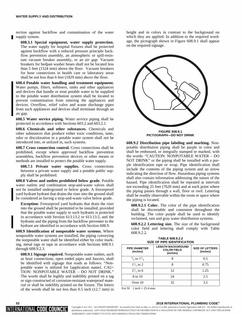
WATER SUPPLY AND DISTRIBUTION
52 2018 INTERNATIONAL PLUMBING CODE®
tection against backflow and contamination of the watersupply system.
608.3.1 Special equipment, water supply protection.The water supply for hospital fixtures shall be protectedagainst backflow with a reduced pressure principle back-flow prevention assembly, an atmospheric or spill-resis-tant vacuum breaker assembly, or an air gap. Vacuumbreakers for bedpan washer hoses shall not be located lessthan 5 feet (1524 mm) above the floor. Vacuum breakersfor hose connections in health care or laboratory areasshall be not less than 6 feet (1829 mm) above the floor.
608.4 Potable water handling and treatment equipment.Water pumps, filters, softeners, tanks and other appliancesand devices that handle or treat potable water to be suppliedto the potable water distribution system shall be located toprevent contamination from entering the appliances anddevices. Overflow, relief valve and waste discharge pipesfrom such appliances and devices shall terminate through anair gap.
608.5 Water service piping. Water service piping shall beprotected in accordance with Sections 603.2 and 603.2.1.
608.6 Chemicals and other substances. Chemicals andother substances that produce either toxic conditions, taste,odor or discoloration in a potable water system shall not beintroduced into, or utilized in, such systems.
608.7 Cross connection control. Cross connections shall beprohibited, except where approved backflow preventionassemblies, backflow prevention devices or other means ormethods are installed to protect the potable water supply.
608.7.1 Private water supplies. Cross connectionsbetween a private water supply and a potable public sup-ply shall be prohibited.
608.8 Valves and outlets prohibited below grade. Potablewater outlets and combination stop-and-waste valves shallnot be installed underground or below grade. A freezeproofyard hydrant hydrant that drains the riser into the ground shallbe considered as having a stop-and-waste valve below grade.
Exception: Freezeproof yard hydrants that drain the riserinto the ground shall be permitted to be installed, providedthat the potable water supply to such hydrants is protectedin accordance with Section 613.13.2 or 613.13.5, and thehydrants and the piping from the backflow preventer to thehydrant are identified in accordance with Section 608.9.
608.9 Identification of nonpotable water systems. Wherenonpotable water systems are installed, the piping conveyingthe nonpotable water shall be identified either by color mark-ing, metal tags or tape in accordance with Sections 608.9.1through 608.9.2.3.
608.9.1 Signage required. Nonpotable water outlets, suchas hose connections, open ended pipes and faucets, shallbe identified with signage that reads as follows: “Non-potable water is utilized for [application name]. CAU-TION: NONPOTABLE WATER – DO NOT DRINK.”The words shall be legibly and indelibly printed on a tagor sign constructed of corrosion-resistant waterproof mate-rial or shall be indelibly printed on the fixture. The lettersof the words shall be not less than 0.5 inch (12.7 mm) in
height and in colors in contrast to the background onwhich they are applied. In addition to the required word-age, the pictograph shown in Figure 608.9.1 shall appearon the required signage.
608.9.2 Distribution pipe labeling and marking. Non-potable distribution piping shall be purple in color andshall be embossed, or integrally stamped or marked, withthe words: “CAUTION: NONPOTABLE WATER – DONOT DRINK” or the piping shall be installed with a pur-ple identification tape or wrap. Pipe identification shallinclude the contents of the piping system and an arrowindicating the direction of flow. Hazardous piping systemsshall also contain information addressing the nature of thehazard. Pipe identification shall be repeated at intervalsnot exceeding 25 feet (7620 mm) and at each point wherethe piping passes through a wall, floor or roof. Letteringshall be readily observable within the room or space wherethe piping is located.
608.9.2.1 Color. The color of the pipe identificationshall be discernable and consistent throughout thebuilding. The color purple shall be used to identifyreclaimed, rain and gray water distribution systems.
608.9.2.2 Lettering size. The size of the backgroundcolor field and lettering shall comply with Table608.9.2.2.
TABLE 608.9.2.2SIZE OF PIPE IDENTIFICATION
For SI 1 inch = 25.4 mm.
PIPE DIAMETER (inches)
LENGTH BACKGROUND COLOR FIELD
(inches)
SIZE OF LETTERS (inches)
3/4 to 11/4 8 0.5
11/2 to 2 8 0.75
21/2 to 6 12 1.25
8 to 10 24 2.5
Over 10 32 3.5
FIGURE 608.9.1PICTOGRAPH—DO NOT DRINK
Copyright © 2017 ICC. ALL RIGHTS RESERVED. Accessed by Eric Fitch on May 15, 2018 8:17:14 AM pursuant to License Agreement with ICC. No further reproduction ordistribution authorized. ANY UNAUTHORIZED REPRODUCTION OR DISTRIBUTION IS A VIOLATION OF THE FEDERAL COPYRIGHT ACT AND THE LICENSEAGREEMENT, AND SUBJECT TO CIVIL AND CRIMINAL PENALTIES THEREUNDER.

WATER SUPPLY AND DISTRIBUTION
2018 INTERNATIONAL PLUMBING CODE® 53
TABLE 608.1APPLICATION OF BACKFLOW PREVENTERS
For SI: 1 inch = 25.4 mm. a. Low hazard—See Pollution (Section 202).
High hazard—See Contamination (Section 202). b. See Backpressure, low head (Section 202).
See Backsiphonage (Section 202).
DEVICE DEGREE OF HAZARDa APPLICATIONb APPLICABLE STANDARDS
Backflow prevention assemblies:
Double check backflow prevention assembly and double check fire protection backflow prevention assembly
Low hazard Backpressure or backsiphonage Sizes 3/8″–16″
ASSE 1015, AWWA C510,CSA B64.5, CSA B64.5.1
Double check detector fire protection backflow prevention assemblies
Low hazard Backpressure or backsiphonage Sizes 2″–16″ ASSE 1048
Pressure vacuum breaker assembly High or low hazard Backsiphonage only Sizes 1/2″–2″ ASSE 1020, CSA B64.1.2
Reduced pressure principle backflow prevention assembly and reduced pressure
principle fire protection backflow assemblyHigh or low hazard
Backpressure or backsiphonage Sizes 3/8″–16″
ASSE 1013, AWWA C511, CSA B64.4, CSA B64.4.1
Reduced pressure detector fire protection backflow prevention assemblies
High or low hazard Backsiphonage or backpressure (Fire sprinkler systems)
ASSE 1047
Spill-resistant vacuum breaker assembly High or low hazard Backsiphonage only Sizes 1/4″–2″ ASSE 1056; CSA B64.1.3
Backflow preventer plumbing devices:
Antisiphon-type fill valves for gravity water closet flush tanks
High hazard Backsiphonage only ASSE 1002/ASME A112.1002/CSA B125.12, CSA B125.3
Backflow preventer for carbonated beverage machines
Low hazard Backpressure or backsiphonage Sizes 1/4″–3/8″
ASSE 1022
Backflow preventer with intermediate atmospheric vents
Low hazard Backpressure or backsiphonage Sizes 1/4″–3/4″
ASSE 1012, CSA B64.3
Dual-check-valve-type backflow preventer Low hazard Backpressure or backsiphonage Sizes 1/4″–1″
ASSE 1024, CSA B64.6
Hose connection backflow preventer High or low hazardLow head backpressure, rated working pressure, backpressure or backsiphonage Sizes 1/2″–1″
ASME A112.21.3, ASSE 1052, CSA B64.2.1.1
Hose connection vacuum breaker High or low hazardLow head backpressure or backsiphonage Sizes 1/2″, 3/4″, 1″
ASME A112.21.3, ASSE 1011, CSA B64.2, CSA B64.2.1
Laboratory faucet backflow preventer High or low hazardLow head backpressure and backsiphonage
ASSE 1035, CSA B64.7
Pipe-applied atmospheric-type vacuum breaker High or low hazardBacksiphonage onlySizes 1/4″– 4″
ASSE 1001, CSA B64.1.1
Vacuum breaker wall hydrants, frost-resistant, automatic-draining type High or low hazard
Low head backpressure or backsiphonage Sizes 3/4″, 1″
ASME A112.21.3, ASSE 1019, CSA B64.2.2
Other means or methods:
Air gap High or low hazard Backsiphonage or backpressure ASME A112.1.2
Air gap fittings for use with plumbing fixtures, appliances and appurtenances
High or low hazard Backsiphonage or backpressure ASME A112.1.3
Barometric loop High or low hazard Backsiphonage only (See Section 608.14.4)
Copyright © 2017 ICC. ALL RIGHTS RESERVED. Accessed by Eric Fitch on May 15, 2018 8:17:14 AM pursuant to License Agreement with ICC. No further reproduction ordistribution authorized. ANY UNAUTHORIZED REPRODUCTION OR DISTRIBUTION IS A VIOLATION OF THE FEDERAL COPYRIGHT ACT AND THE LICENSEAGREEMENT, AND SUBJECT TO CIVIL AND CRIMINAL PENALTIES THEREUNDER.

WATER SUPPLY AND DISTRIBUTION
54 2018 INTERNATIONAL PLUMBING CODE®
608.9.2.3 Identification tape. Where used, identifica-tion tape shall be not less than 3 inches (76 mm) wideand have white or black lettering on a purple field stat-ing “CAUTION: NONPOTABLE WATER – DO NOTDRINK.” Identification tape shall be installed on top ofnonpotable rainwater distribution pipes, fastened notless than every 10 feet (3048 mm) to each pipe lengthand run continuously the entire length of the pipe.
608.10 Reutilization prohibited. Water utilized for the heat-ing or cooling of equipment or other processes shall not bereturned to the potable water system. Such water shall be dis-charged into a drainage system through an air gap or shall beutilized for nonpotable purposes.
608.11 Reuse of piping. Piping that has been utilized for anypurpose other than conveying potable water shall not be uti-lized for conveying potable water.
608.12 Potable water tanks. Where in contact with potablewater intended for drinking water, water tanks, coatings forthe inside of tanks and liners for water tanks shall conform toNSF 61. The interior surface of a potable water tank shall notbe lined, painted or repaired with any material that changesthe taste, odor, color or potability of the water supply whenthe tank is placed in, or returned to, service.
608.13 Pumps and other appliances. Water pumps, filters,softeners, tanks and other devices that handle or treat potablewater shall be protected against contamination.
608.14 Backflow protection. Means of protection againstbackflow shall be provided in accordance with Sections609.14.1 through 608.14.9.
608.14.1 Air gap. The minimum required air gap shall bemeasured vertically from the lowest end of a potable wateroutlet to the flood level rim of the fixture or receptacle intowhich such potable water outlet discharges. Air gaps shallcomply with ASME A112.1.2 and air gap fittings shallcomply with ASME A112.1.3. Products that are listed andlabeled to ASME A112.1.2 or ASME A112.1.3 shall beconsidered to be in compliance with this section.
608.14.2 Reduced pressure principle backflow preven-tion assemblies. Reduced pressure principle backflowprevention assemblies shall conform to ASSE 1013,AWWA C511, CSA B64.4 or CSA B64.4.1. Reducedpressure detector assembly backflow preventers shall con-form to ASSE 1047. These devices shall be permitted tobe installed where subject to continuous pressure condi-tions. The relief opening shall discharge by air gap andshall be prevented from being submerged.
608.14.3 Backflow preventer with intermediate atmo-spheric vent. Backflow preventers with intermediateatmospheric vents shall conform to ASSE 1012 or CSAB64.3. These devices shall be permitted to be installedwhere subject to continuous pressure conditions. Therelief opening shall discharge by air gap and shall be pre-vented from being submerged.
608.14.4 Barometric loop. Barometric loops shall pre-cede the point of connection and shall extend vertically toa height of 35 feet (10 668 mm). A barometric loop shall
only be utilized as an atmospheric-type or pressure-typevacuum breaker.
608.14.5 Pressure vacuum breaker assemblies. Pressurevacuum breaker assemblies shall comply with ASSE 1020or CSA B64.1.2. Spill-resistant vacuum breaker assem-blies shall comply with ASSE 1056 or CSA B64.1.3.These assemblies shall be installed with the critical levelof the assembly located not less than 12 inches (305 mm)above all downstream piping and outlets. Pressure vacuumbreaker assemblies shall not be installed in locationswhere spillage could cause damage to the structure.
608.14.6 Atmospheric-type vacuum breakers. Pipe-applied atmospheric-type vacuum breakers shall conformto ASSE 1001 or CSA B64.1.1. Hose-connection vacuumbreakers shall conform to ASME A112.21.3, ASSE 1011,ASSE 1019, ASSE 1035, ASSE 1052, CSA B64.2, CSAB64.2.1, CSA B64.2.1.1, CSA B64.2.2 or CSA B64.7.These devices shall operate under normal atmosphericpressure when the critical level is installed at the requiredheight.
608.14.7 Double check backflow prevention assemblies.Double check backflow prevention assemblies shall con-form to ASSE 1015, CSA B64.5, CSA B64.5.1 or AWWAC510. Double check detector fire protection backflow pre-vention assemblies shall conform to ASSE 1048. Theseassemblies shall be capable of operating under continuouspressure conditions.
608.14.8 Chemical dispenser backflow devices. Back-flow devices for chemical dispensers shall comply withASSE 1055 or shall be equipped with an air gap fitting.
608.14.9 Dual check backflow preventer. Dual checkbackflow preventers shall conform to ASSE 1024 or CSAB64.6.
608.15 Location of backflow preventers. Access shall beprovided to backflow preventers as specified by the manufac-turer’s instructions.
608.15.1 Outdoor enclosures for backflow preventiondevices. Outdoor enclosures for backflow preventiondevices shall comply with ASSE 1060.
608.15.2 Protection of backflow preventers. Backflowpreventers shall not be located in areas subject to freezingexcept where they can be removed by means of unions orare protected from freezing by heat, insulation or both.
608.15.2.1 Relief port piping. The termination of thepiping from the relief port or air gap fitting of a back-flow preventer shall discharge to an approved indirectwaste receptor or to the outdoors where it will not causedamage or create a nuisance.
608.16 Protection of potable water outlets. Potable wateropenings and outlets shall be protected against backflow inaccordance with Section 608.16.1, 608.16.2, 608.16.3,608.16.4, 608.16.4.1 or 608.16.4.2.
608.16.1 Protection by air gap. Openings and outletsshall be protected by an air gap between the opening andthe fixture flood level rim as specified in Table 608.16.1.Openings and outlets equipped for hose connection shallbe protected by means other than an air gap.
�
Copyright © 2017 ICC. ALL RIGHTS RESERVED. Accessed by Eric Fitch on May 15, 2018 8:17:14 AM pursuant to License Agreement with ICC. No further reproduction ordistribution authorized. ANY UNAUTHORIZED REPRODUCTION OR DISTRIBUTION IS A VIOLATION OF THE FEDERAL COPYRIGHT ACT AND THE LICENSEAGREEMENT, AND SUBJECT TO CIVIL AND CRIMINAL PENALTIES THEREUNDER.
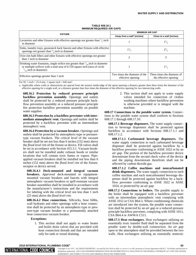
WATER SUPPLY AND DISTRIBUTION
2018 INTERNATIONAL PLUMBING CODE® 55
608.16.2 Protection by reduced pressure principlebackflow prevention assembly. Openings and outletsshall be protected by a reduced pressure principle back-flow prevention assembly or a reduced pressure principlefire protection backflow prevention assembly on potablewater supplies.
608.16.3 Protection by a backflow preventer with inter-mediate atmospheric vent. Openings and outlets shall beprotected by a backflow preventer with an intermediateatmospheric vent.
608.16.4 Protection by a vacuum breaker. Openings andoutlets shall be protected by atmospheric-type or pressure-type vacuum breakers. The critical level of the vacuumbreaker shall be set not less than 6 inches (152 mm) abovethe flood level rim of the fixture or device. Fill valves shallbe set in accordance with Section 415.3.1. Vacuum break-ers shall not be installed under exhaust hoods or similarlocations that will contain toxic fumes or vapors. Pipe-applied vacuum breakers shall be installed not less than 6inches (152 mm) above the flood level rim of the fixture,receptor or device served.
608.16.4.1 Deck-mounted and integral vacuumbreakers. Approved deck-mounted or equipment-mounted vacuum breakers and faucets with integralatmospheric vacuum breakers or spill-resistant vacuumbreaker assemblies shall be installed in accordance withthe manufacturer’s instructions and the requirementsfor labeling with the critical level not less than 1 inch(25 mm) above the flood level rim.
608.16.4.2 Hose connections. Sillcocks, hose bibbs,wall hydrants and other openings with a hose connec-tion shall be protected by an atmospheric-type or pres-sure-type vacuum breaker or a permanently attachedhose connection vacuum breaker.
Exceptions:1. This section shall not apply to water heater
and boiler drain valves that are provided withhose connection threads and that are intendedonly for tank or vessel draining.
2. This section shall not apply to water supplyvalves intended for connection of clotheswashing machines where backflow preventionis otherwise provided or is integral with themachine.
608.17 Connections to the potable water system. Connec-tions to the potable water system shall conform to Sections608.17.1 through 608.17.10.
608.17.1 Beverage dispensers. The water supply connec-tion to beverage dispensers shall be protected againstbackflow in accordance with Sections 608.17.1.1 and608.17.1.2.
608.17.1.1 Carbonated beverage dispensers. Thewater supply connection to each carbonated beveragedispenser shall be protected against backflow by abackflow preventer conforming to ASSE 1022 or by anair gap. The portion of the backflow preventer devicedownstream from the second check valve of the deviceand the piping downstream therefrom shall not beaffected by carbon dioxide gas.
608.17.1.2 Coffee machines and noncarbonateddrink dispensers. The water supply connection to eachcoffee machine and each noncarbonated beverage dis-penser shall be protected against backflow by a back-flow preventer conforming to ASSE 1022 or ASSE1024, or protected by an air gap.
608.17.2 Connections to boilers. The potable supply tothe boiler shall be equipped with a backflow preventerwith an intermediate atmospheric vent complying withASSE 1012 or CSA B64.3. Where conditioning chemicalsare introduced into the system, the potable water connec-tion shall be protected by an air gap or a reduced pressureprinciple backflow preventer, complying with ASSE 1013,CSA B64.4 or AWWA C511.
608.17.3 Heat exchangers. Heat exchangers utilizing anessentially toxic transfer fluid shall be separated from thepotable water by double-wall construction. An air gapopen to the atmosphere shall be provided between the twowalls. Heat exchangers utilizing an essentially nontoxic
TABLE 608.16.1MINIMUM REQUIRED AIR GAPS
For SI: 1 inch = 25.4 mm, 1 square inch = 645 mm2.a. Applicable where walls or obstructions are spaced from the nearest inside-edge of the spout opening a distance greater than three times the diameter of the
effective opening for a single wall, or a distance greater than four times the diameter of the effective opening for two intersecting walls.
FIXTUREMINIMUM AIR GAP
Away from a walla (inches) Close to a wall (inches)
Lavatories and other fixtures with effective openings not greater than 1/2 inch in diameter
1 11/2
Sinks, laundry trays, gooseneck back faucets and other fixtures with effective openings not greater than 3/4 inch in diameter
11/2 21/2
Over-rim bath fillers and other fixtures with effective openings not greater than 1 inch in diameter
2 3
Drinking water fountains, single orifice not greater than 7/16 inch in diameter or multiple orifices with a total area of 0.150 square inch (area of circle
7/16 inch in diameter) 1 11/2
Effective openings greater than 1 inch Two times the diameter of the
effective openingThree times the diameter of
the effective opening
Copyright © 2017 ICC. ALL RIGHTS RESERVED. Accessed by Eric Fitch on May 15, 2018 8:17:14 AM pursuant to License Agreement with ICC. No further reproduction ordistribution authorized. ANY UNAUTHORIZED REPRODUCTION OR DISTRIBUTION IS A VIOLATION OF THE FEDERAL COPYRIGHT ACT AND THE LICENSEAGREEMENT, AND SUBJECT TO CIVIL AND CRIMINAL PENALTIES THEREUNDER.

WATER SUPPLY AND DISTRIBUTION
56 2018 INTERNATIONAL PLUMBING CODE®
transfer fluid shall be permitted to be of single-wall con-struction.
608.17.4 Connections to automatic fire sprinkler sys-tems and standpipe systems. The potable water supply toautomatic fire sprinkler and standpipe systems shall beprotected against backflow by a double check backflowprevention assembly, a double check fire protection back-flow prevention assembly or a reduced pressure principlefire protection backflow prevention assembly.
Exceptions:1. Where systems are installed as a portion of the
water distribution system in accordance with therequirements of this code and are not providedwith a fire department connection, isolation ofthe water supply system shall not be required.
2. Isolation of the water distribution system is notrequired for deluge, preaction or dry pipe sys-tems.
608.17.4.1 Additives or nonpotable source. Wheresystems under continuous pressure contain chemicaladditives or antifreeze, or where systems are connectedto a nonpotable secondary water supply, the potablewater supply shall be protected against backflow by areduced pressure principle backflow prevention assem-bly or a reduced pressure principle fire protection back-flow prevention assembly. Where chemical additives orantifreeze are added to only a portion of an automaticfire sprinkler or standpipe system, the reduced pressureprinciple backflow prevention assembly or the reducedpressure principle fire protection backflow preventionassembly shall be permitted to be located so as to iso-late that portion of the system. Where systems are notunder continuous pressure, the potable water supplyshall be protected against backflow by an air gap or anatmospheric vacuum breaker conforming to ASSE1001 or CSA B64.1.1.
608.17.5 Connections to lawn irrigation systems. Thepotable water supply to lawn irrigation systems shall beprotected against backflow by an atmospheric vacuumbreaker, a pressure vacuum breaker assembly or a reducedpressure principle backflow prevention assembly. Valvesshall not be installed downstream from an atmosphericvacuum breaker. Where chemicals are introduced into thesystem, the potable water supply shall be protected againstbackflow by a reduced pressure principle backflow pre-vention assembly.
608.17.6 Connections subject to backpressure. Where apotable water connection is made to a nonpotable line, fix-ture, tank, vat, pump or other equipment subject to high-hazard backpressure, the potable water connection shall beprotected by a reduced pressure principle backflow pre-vention assembly.
608.17.7 Chemical dispensers. Where chemical dispens-ers connect to the potable water distribution system, thewater supply system shall be protected against backflow inaccordance with Section 608.14.1, 608.14.2, 608.14.5,608.14.6, 608.14.8 or 608.14.9.
608.17.8 Portable cleaning equipment. Where the porta-ble cleaning equipment connects to the water distributionsystem, the water supply system shall be protected againstbackflow in accordance with Section 608.14.1, 608.14.2,608.14.3, 608.14.7 or 608.14.8.
608.17.9 Dental pumping equipment. The water supplyconnection to each dental pumping equipment system, thewater supply system shall be protected against backflow inaccordance with Section 608.14.1, 608.14.2, 608.14.5,608.14.6 or 608.14.8.
608.17.10 Humidifiers. The water supply connection tohumidifiers that do not have internal backflow protectionshall be protected against backflow by a backflow pre-venter conforming to ASSE 1012 or by an air gap.
608.18 Protection of individual water supplies. An individ-ual water supply shall be located and constructed so as to besafeguarded against contamination in accordance with Sec-tions 608.18.1 through 608.18.8.
608.18.1 Well locations. A potable ground water sourceor pump suction line shall not be located closer to poten-tial sources of contamination than the distances shown inTable 608.18.1. In the event the underlying rock structureis limestone or fragmented shale, the local or state healthdepartment shall be consulted on well site location. Thedistances in Table 608.18.1 constitute minimum separa-tion and shall be increased in areas of creviced rock orlimestone, or where the direction of movement of theground water is from sources of contamination toward thewell.
TABLE 608.18.1DISTANCE FROM CONTAMINATION TO
PRIVATE WATER SUPPLIES AND PUMP SUCTION LINES
For SI: 1 foot = 304.8 mm.
608.18.2 Elevation. Well sites shall be positively drainedand shall be at higher elevations than potential sources ofcontamination.
608.18.3 Depth. Private potable well supplies shall not bedeveloped from a water table less than 10 feet (3048 mm)below the ground surface.
608.18.4 Water-tight casings. Each well shall be pro-vided with a water-tight casing extending to not less than10 feet (3048 mm) below the ground surface. Casingsshall extend not less than 6 inches (152 mm) above thewell platform. Casings shall be large enough to permit
SOURCE OF CONTAMINATION DISTANCE (feet)
Barnyard 100
Farm silo 25
Pasture 100
Pumphouse floor drain of cast iron draining to ground surface
2
Seepage pits 50
Septic tank 25
Sewer 10
Subsurface disposal fields 50
Subsurface pits 50
Copyright © 2017 ICC. ALL RIGHTS RESERVED. Accessed by Eric Fitch on May 15, 2018 8:17:14 AM pursuant to License Agreement with ICC. No further reproduction ordistribution authorized. ANY UNAUTHORIZED REPRODUCTION OR DISTRIBUTION IS A VIOLATION OF THE FEDERAL COPYRIGHT ACT AND THE LICENSEAGREEMENT, AND SUBJECT TO CIVIL AND CRIMINAL PENALTIES THEREUNDER.
WATER SUPPLY AND DISTRIBUTION
2018 INTERNATIONAL PLUMBING CODE® 57
installation of a separate drop pipe. Casings shall be sealedat the bottom in an impermeable stratum or extend severalfeet into the water-bearing stratum.
608.18.5 Drilled or driven well casings. Drilled or drivenwell casings shall be of steel or other approved material.Where drilled wells extend into a rock formation, the wellcasing shall extend to and set firmly in the formation. Theannular space between the earth and the outside of the cas-ing shall be filled with cement grout to a depth of not lessthan 10 feet (3048 mm) below the ground surface. In aninstance of casing to rock installation, the grout shallextend to the rock surface.
608.18.6 Dug or bored well casings. Dug or bored wellcasings shall be of water-tight concrete, tile or galvanizedor corrugated metal pipe extending to not less than 10 feet(3048 mm) below the ground surface. Where the watertable is more than 10 feet (3048 mm) below the groundsurface, the water-tight casing shall extend below the tablesurface. Well casings for dug wells or bored wells con-structed with sections of concrete, tile or galvanized orcorrugated metal pipe shall be surrounded by 6 inches(152 mm) of grout poured into the hole between the out-side of the casing and the ground and extending not lessthan 10 feet (3048 mm) below the ground surface.
608.18.7 Cover. Potable water wells shall be equippedwith an overlapping water-tight cover at the top of the wellcasing or pipe sleeve such that contaminated water orother substances are prevented from entering the wellthrough the annular opening at the top of the well casing,wall or pipe sleeve. Covers shall extend downward notless than 2 inches (51 mm) over the outside of the wellcasing or wall. A dug well cover shall be provided with apipe sleeve permitting the withdrawal of the pump suctionpipe, cylinder or jet body without disturbing the cover.Where pump sections or discharge pipes enter or leave awell through the side of the casing, the circle of contactshall be water tight.
608.18.8 Drainage. Potable water wells and springs shallbe constructed such that surface drainage will be divertedaway from the well or spring.
SECTION 609HEALTH CARE PLUMBING
609.1 Scope. This section shall govern those aspects of healthcare plumbing systems that differ from plumbing systems inother structures. Health care plumbing systems shall conformto the requirements of this section in addition to the other re-quirements of this code. The provisions of this section shallapply to the special devices and equipment installed andmaintained in the following occupancies: Group I-1, Group I-2, Group B ambulatory care facilities, medical offices,research and testing laboratories, and Group F facilities man-ufacturing pharmaceutical drugs and medicines.
609.2 Water service. Hospitals shall have two water servicepipes installed in such a manner so as to minimize the poten-tial for an interruption of the supply of water in the event of awater main or water service pipe failure.
609.3 Hot water. Hot water shall be provided to supply all ofthe hospital fixture, kitchen and laundry requirements. Spe-cial fixtures and equipment shall have hot water supplied at atemperature specified by the manufacturer. The hot watersystem shall be installed in accordance with Section 607.
609.4 Vacuum breaker installation. Vacuum breakers shallbe installed not less than 6 inches (152 mm) above the floodlevel rim of the fixture or device in accordance with Section608. The flood level rim of hose connections shall be themaximum height at which any hose is utilized.
609.5 Prohibited water closet and clinical sink supply. Jet-or water-supplied orifices, except those supplied by the flushconnections, shall not be located in or connected with a watercloset bowl or clinical sink. This section shall not prohibit anapproved bidet installation.
609.6 Clinical, hydrotherapeutic and radiological equip-ment. Clinical, hydrotherapeutic, radiological or any equip-ment that is supplied with water or that discharges to thewaste system shall conform to the requirements of this sec-tion and Section 608.
609.7 Condensate drain trap seal. A water supply shall beprovided for cleaning, flushing and resealing the condensatetrap, and the trap shall discharge through an air gap in accor-dance with Section 608.
609.8 Valve leakage diverter. Each water sterilizer filledwith water through directly connected piping shall beequipped with an approved leakage diverter or bleed line onthe water supply control valve to indicate and conduct anyleakage of unsterile water away from the sterile zone.
SECTION 610DISINFECTION OF POTABLE WATER SYSTEM
610.1 General. New potable water systems shall be purgedof deleterious matter and disinfected prior to utilization. Themethod to be followed shall be that prescribed by the healthauthority or water purveyor having jurisdiction or, in theabsence of a prescribed method, the procedure described ineither AWWA C651 or AWWA C652, or as described in thissection. This requirement shall apply to “on-site” or “in-plant” fabrication of a system or to a modular portion of asystem.
1. The pipe system shall be flushed with clean, potablewater until dirty water does not appear at the points ofoutlet.
2. The system or part thereof shall be filled with a water/chlorine solution containing not less than 50 parts permillion (50 mg/L) of chlorine, and the system or partthereof shall be valved off and allowed to stand for 24hours; or the system or part thereof shall be filled with awater/chlorine solution containing not less than 200parts per million (200 mg/L) of chlorine and allowed tostand for 3 hours.
3. Following the required standing time, the system shallbe flushed with clean potable water until the chlorine ispurged from the system.
Copyright © 2017 ICC. ALL RIGHTS RESERVED. Accessed by Eric Fitch on May 15, 2018 8:17:14 AM pursuant to License Agreement with ICC. No further reproduction ordistribution authorized. ANY UNAUTHORIZED REPRODUCTION OR DISTRIBUTION IS A VIOLATION OF THE FEDERAL COPYRIGHT ACT AND THE LICENSEAGREEMENT, AND SUBJECT TO CIVIL AND CRIMINAL PENALTIES THEREUNDER.
WATER SUPPLY AND DISTRIBUTION
58 2018 INTERNATIONAL PLUMBING CODE®
4. The procedure shall be repeated where shown by a bac-teriological examination that contamination remainspresent in the system.
SECTION 611DRINKING WATER TREATMENT UNITS
611.1 Design. Point-of-use reverse osmosis drinking watertreatement units shall comply with NSF 58 or CSA B483.1.Drinking water treatment units shall meet the requirements ofNSF 42, NSF 44, NSF 53, NSF 62 or CSA B483.1.
611.2 Reverse osmosis systems. The discharge from areverse osmosis drinking water treatment unit shall enter thedrainage system through an air gap or an air gap device thatmeets the requirements of NSF 58 or CSA B483.1.
611.3 Connection tubing. The tubing to and from drinkingwater treatment units shall be of a size and material as recom-mended by the manufacturer. The tubing shall comply withNSF 14, NSF 42, NSF 44, NSF 53, NSF 58 or NSF 61.
SECTION 612SOLAR SYSTEMS
612.1 Solar systems. The construction, installation, alter-ations and repair of systems, equipment and appliancesintended to utilize solar energy for space heating or cooling,domestic hot water heating, swimming pool heating or pro-cess heating shall be in accordance with the InternationalMechanical Code.
SECTION 613TEMPERATURE CONTROL DEVICES AND VALVES613.1 Temperature-actuated mixing valves. Temperature-actuated mixing valves, which are installed to reduce watertemperatures to defined limits, shall comply with ASSE1017. Such valves shall be installed at the hot water source.
Copyright © 2017 ICC. ALL RIGHTS RESERVED. Accessed by Eric Fitch on May 15, 2018 8:17:14 AM pursuant to License Agreement with ICC. No further reproduction ordistribution authorized. ANY UNAUTHORIZED REPRODUCTION OR DISTRIBUTION IS A VIOLATION OF THE FEDERAL COPYRIGHT ACT AND THE LICENSEAGREEMENT, AND SUBJECT TO CIVIL AND CRIMINAL PENALTIES THEREUNDER.

2018 INTERNATIONAL PLUMBING CODE® 59
CHAPTER 7
SANITARY DRAINAGE
User note:
About this chapter: Chapter 7 regulates the methods and piping systems that remove water that has served a purpose such as flushingwater closets, bathing, culinary activities and equipment discharges. The types of materials, drainage fitting and the connection methods arecovered for these systems that begin at the receiving fixtures and end at the point of disposal for the liquid waste. A design method for a grav-ity flow system of vertical and horizontal piping is provided based on the probability of flows from specific fixtures. Vacuum and pumped typesof liquid waste removal methods are also regulated by this chapter.
SECTION 701GENERAL
701.1 Scope. The provisions of this chapter shall govern thematerials, design, construction and installation of sanitarydrainage systems.
701.2 Connection to sewer required. Sanitary drainage pip-ing from plumbing fixtures in buildings and sanitary drainagepiping systems from premises shall be connected to a publicsewer. Where a public sewer is not available, the sanitarydrainage piping and systems shall be connected to a privatesewage disposal system in compliance with state or localrequirements. Where state or local requirements do not existfor private sewage disposal systems, the sanitary drainagepiping and systems shall be connected to an approved privatesewage disposal system that is in accordance with the Inter-national Private Sewage Disposal Code.
Exception: Sanitary drainage piping and systems that con-vey only the discharge from bathtubs, showers, lavatories,clothes washers and laundry trays shall not be required toconnect to a public sewer or to a private sewage disposalsystem provided that the piping or systems are connectedto a system in accordance with Chapter 13 or 14.
701.3 Separate sewer connection. A building having plumb-ing fixtures installed and intended for human habitation,occupancy or use on premises abutting on a street, alley oreasement in which there is a public sewer shall have a sepa-rate connection with the sewer. Where located on the samelot, multiple buildings shall not be prohibited from connect-ing to a common building sewer that connects to the publicsewer.
701.4 Sewage treatment. Sewage or other waste from aplumbing system that is deleterious to surface or subsurfacewaters shall not be discharged into the ground or into anywaterway unless it has first been rendered innocuous throughsubjection to an approved form of treatment.
701.5 Damage to drainage system or public sewer. Wastedetrimental to the public sewer system or to the functioningof the sewage-treatment plant shall be treated and disposed ofin accordance with Section 1003 as directed by the code offi-cial.
701.6 Tests. The sanitary drainage system shall be tested inaccordance with Section 312.
701.7 Engineered systems. Engineered sanitary drainagesystems shall conform to the provisions of Sections 316 and713.
SECTION 702MATERIALS
702.1 Above-ground sanitary drainage and vent pipe.Above-ground soil, waste and vent pipe shall conform to oneof the standards listed in Table 702.1.
TABLE 702.1ABOVE-GROUND DRAINAGE AND VENT PIPE
MATERIAL STANDARD
Acrylonitrile butadiene styrene (ABS) plastic pipe in IPS diameters, including Schedule 40, DR 22 (PS 200) and DR 24 (PS 140); with a solid, cellular core or composite wall
ASTM D2661; ASTM F628;ASTM F1488; CSA B181.1
Cast-iron pipe ASTM A74; ASTM A888;CISPI 301
Copper or copper-alloy pipe ASTM B42; ASTM B43; ASTM B302
Copper or copper-alloy tubing (Type K, L, M or DWV)
ASTM B75; ASTM B88;ASTM B251; ASTM B306
Galvanized steel pipe ASTM A53
Glass pipe ASTM C1053
Polyolefin pipe ASTM F1412;CSA B181.3
Polyvinyl chloride (PVC) plastic pipe in IPS diameters, inclu-ing Schedule 40, DR 22 (PS 200), and DR 24 (PS 140); with a solid, cellular core or composite wall
ASTM D2665; ASTM F891;ASTM F1488; CSA B181.2
Polyvinyl chloride (PVC) plastic pipe with a 3.25-inchO.D. and a solid, cellularcore or composite wall
ASTM D2949, ASTM F1488
Polyvinylidene fluoride (PVDF) plastic pipe
ASTM F1673; CSA B181.3
Stainless steel drainage systems, Types 304 and 316L
ASME A112.3.1
�
Copyright © 2017 ICC. ALL RIGHTS RESERVED. Accessed by Eric Fitch on May 15, 2018 8:17:14 AM pursuant to License Agreement with ICC. No further reproduction ordistribution authorized. ANY UNAUTHORIZED REPRODUCTION OR DISTRIBUTION IS A VIOLATION OF THE FEDERAL COPYRIGHT ACT AND THE LICENSEAGREEMENT, AND SUBJECT TO CIVIL AND CRIMINAL PENALTIES THEREUNDER.
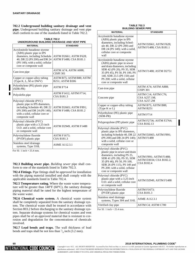
SANITARY DRAINAGE
60 2018 INTERNATIONAL PLUMBING CODE®
702.2 Underground building sanitary drainage and ventpipe. Underground building sanitary drainage and vent pipeshall conform to one of the standards listed in Table 702.2.
702.3 Building sewer pipe. Building sewer pipe shall con-form to one of the standards listed in Table 702.3.
702.4 Fittings. Pipe fittings shall be approved for installationwith the piping material installed and shall comply with theapplicable standards listed in Table 702.4.
702.5 Temperature rating. Where the waste water tempera-ture will be greater than 140°F (60°C), the sanitary drainagepiping material shall be rated for the highest temperature ofthe waste water.
702.6 Chemical waste system. A chemical waste systemshall be completely separated from the sanitary drainage sys-tem. The chemical waste shall be treated in accordance withSection 803.2 before discharging to the sanitary drainage sys-tem. Separate drainage systems for chemical wastes and ventpipes shall be of an approved material that is resistant to cor-rosion and degradation for the concentrations of chemicalsinvolved.
702.7 Lead bends and traps. The wall thickness of leadbends and traps shall be not less than 1/8 inch (3.2 mm).
TABLE 702.2UNDERGROUND BUILDING DRAINAGE AND VENT PIPE
For SI: 1 inch = 25.4 mm.
MATERIAL STANDARD
Acrylonitrile butadiene styrene (ABS) plastic pipe in IPS diameters, including Schedule 40, DR 22 (PS 200) and DR 24 (PS 140); with a solid, cellular core or composite wall
ASTM D2661; ASTM F628; ASTM F1488; CSA B181.1
Cast-iron pipe ASTM A74; ASTM A888; CISPI 301
Copper or copper-alloy tubing (Type K, L, M or DWV)
ASTM B75; ASTM B88; ASTM B251; ASTM B306
Polyethylene (PE) plastic pipe (SDR-PR)
ASTM F714
Polyolefin pipe ASTM F1412; ASTM F714;CSA B181.3
Polyvinyl chloride (PVC)plastic pipe in IPS diameters, including Schedule 40, DR 22 (PS 200) and DR 24 (PS 140); with a solid, cellular core or composite wall
ASTM D2665; ASTM F891; ASTM F1488; CSA B181.2
Polyvinyl chloride (PVC)plastic pipe with a 3.25-inch O.D. and a solid, cellular core or composite wall
ASTM D2949, ASTM F1488
Polyvinylidene fluoride (PVDF) plastic pipe
ASTM F1673; CSA B181.3
Stainless steel drainage systems, Type 316L
ASME A112.3.1
TABLE 702.3BUILDING SEWER PIPE
For SI: 1 inch = 25.4 mm.
MATERIAL STANDARD
Acrylonitrile butadiene styrene(ABS) plastic pipe in IPS diameters, including Sched-ule 40, DR 22 (PS 200) and DR 24 (PS 140); with a solid, cellular core or composite wall
ASTM D2661; ASTM F628;ASTM F1488; CSA B181.1
Acrylonitrile butadiene styrene(ABS) plastic pipe in sewer and drain diameters, including SDR 42 (PS 20), PS 35, SDR 35 (PS 45), PS 50, PS 100, PS 140, SDR 23.5 (PS 150) and PS 200; with a solid, cellular core or composite wall
ASTM F1488; ASTM D2751
Cast-iron pipe ASTM A74; ASTM A888;CISPI 301
Concrete pipe ASTM C14; ASTM C76;CSA A257.1M;CSA A257.2M
Copper or copper-alloy tubing (Type K or L)
ASTM B75; ASTM B88;ASTM B251
Polyethylene (PE) plastic pipe (SDR-PR) ASTM F714
Polypropylene (PP) plastic pipeASTM F2736; ASTM F2764; CSA B182.13
Polyvinyl chloride (PVC)plastic pipe in IPS diameters, including Schedule 40, DR 22 (PS 200) and DR 24 (PS 140); with a solid, cellular core or composite wall
ASTM D2665; ASTM F891;ASTM F1488
Polyvinyl chloride (PVC)plastic pipe in sewer and drain diameters, including PS 25, SDR 41 (PS 28), PS 35, SDR 35 (PS 46), PS 50, PS 100, SDR 26 (PS 115), PS 140 and PS 200; with a solid, cellular core or composite wall
ASTM F891; ASTM F1488;ASTM D3034; CSA B182.2;CSA B182.4
Polyvinyl chloride (PVC)plastic pipe with a 3.25-inch O.D. and a solid, cellular core or composite wall
ASTM D2949, ASTM F1488
Polyvinylidene fluoride(PVDF) plastic pipe
ASTM F1673;CSA B181.3
Stainless steel drainagesystems, Types 304 and 316L ASME A112.3.1
Vitrified clay pipe ASTM C4; ASTM C700
Copyright © 2017 ICC. ALL RIGHTS RESERVED. Accessed by Eric Fitch on May 15, 2018 8:17:14 AM pursuant to License Agreement with ICC. No further reproduction ordistribution authorized. ANY UNAUTHORIZED REPRODUCTION OR DISTRIBUTION IS A VIOLATION OF THE FEDERAL COPYRIGHT ACT AND THE LICENSEAGREEMENT, AND SUBJECT TO CIVIL AND CRIMINAL PENALTIES THEREUNDER.
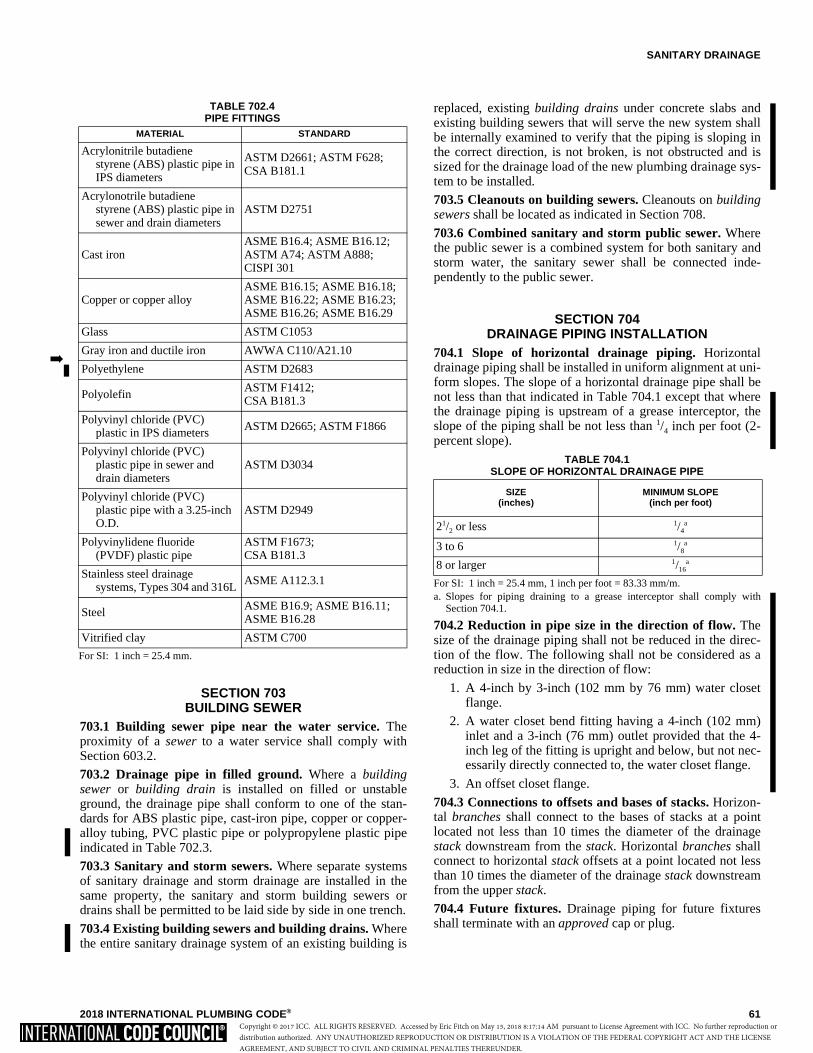
SANITARY DRAINAGE
2018 INTERNATIONAL PLUMBING CODE® 61
SECTION 703BUILDING SEWER
703.1 Building sewer pipe near the water service. Theproximity of a sewer to a water service shall comply withSection 603.2.
703.2 Drainage pipe in filled ground. Where a buildingsewer or building drain is installed on filled or unstableground, the drainage pipe shall conform to one of the stan-dards for ABS plastic pipe, cast-iron pipe, copper or copper-alloy tubing, PVC plastic pipe or polypropylene plastic pipeindicated in Table 702.3.
703.3 Sanitary and storm sewers. Where separate systemsof sanitary drainage and storm drainage are installed in thesame property, the sanitary and storm building sewers ordrains shall be permitted to be laid side by side in one trench.
703.4 Existing building sewers and building drains. Wherethe entire sanitary drainage system of an existing building is
replaced, existing building drains under concrete slabs andexisting building sewers that will serve the new system shallbe internally examined to verify that the piping is sloping inthe correct direction, is not broken, is not obstructed and issized for the drainage load of the new plumbing drainage sys-tem to be installed.
703.5 Cleanouts on building sewers. Cleanouts on buildingsewers shall be located as indicated in Section 708.
703.6 Combined sanitary and storm public sewer. Wherethe public sewer is a combined system for both sanitary andstorm water, the sanitary sewer shall be connected inde-pendently to the public sewer.
SECTION 704DRAINAGE PIPING INSTALLATION
704.1 Slope of horizontal drainage piping. Horizontaldrainage piping shall be installed in uniform alignment at uni-form slopes. The slope of a horizontal drainage pipe shall benot less than that indicated in Table 704.1 except that wherethe drainage piping is upstream of a grease interceptor, theslope of the piping shall be not less than 1/4 inch per foot (2-percent slope).
TABLE 704.1SLOPE OF HORIZONTAL DRAINAGE PIPE
For SI: 1 inch = 25.4 mm, 1 inch per foot = 83.33 mm/m.a. Slopes for piping draining to a grease interceptor shall comply with
Section 704.1.
704.2 Reduction in pipe size in the direction of flow. Thesize of the drainage piping shall not be reduced in the direc-tion of the flow. The following shall not be considered as areduction in size in the direction of flow:
1. A 4-inch by 3-inch (102 mm by 76 mm) water closetflange.
2. A water closet bend fitting having a 4-inch (102 mm)inlet and a 3-inch (76 mm) outlet provided that the 4-inch leg of the fitting is upright and below, but not nec-essarily directly connected to, the water closet flange.
3. An offset closet flange.
704.3 Connections to offsets and bases of stacks. Horizon-tal branches shall connect to the bases of stacks at a pointlocated not less than 10 times the diameter of the drainagestack downstream from the stack. Horizontal branches shallconnect to horizontal stack offsets at a point located not lessthan 10 times the diameter of the drainage stack downstreamfrom the upper stack.
704.4 Future fixtures. Drainage piping for future fixturesshall terminate with an approved cap or plug.
SIZE(inches)
MINIMUM SLOPE(inch per foot)
21/2 or less 1/4a
3 to 6 1/8a
8 or larger 1/16a
TABLE 702.4PIPE FITTINGS
For SI: 1 inch = 25.4 mm.
MATERIAL STANDARD
Acrylonitrile butadienestyrene (ABS) plastic pipe in IPS diameters
ASTM D2661; ASTM F628;CSA B181.1
Acrylonotrile butadienestyrene (ABS) plastic pipe in sewer and drain diameters
ASTM D2751
Cast iron ASME B16.4; ASME B16.12;ASTM A74; ASTM A888;CISPI 301
Copper or copper alloy ASME B16.15; ASME B16.18;ASME B16.22; ASME B16.23;ASME B16.26; ASME B16.29
Glass ASTM C1053
Gray iron and ductile iron AWWA C110/A21.10
Polyethylene ASTM D2683
Polyolefin ASTM F1412;CSA B181.3
Polyvinyl chloride (PVC)plastic in IPS diameters ASTM D2665; ASTM F1866
Polyvinyl chloride (PVC)plastic pipe in sewer and drain diameters
ASTM D3034
Polyvinyl chloride (PVC)plastic pipe with a 3.25-inch O.D.
ASTM D2949
Polyvinylidene fluoride(PVDF) plastic pipe
ASTM F1673;CSA B181.3
Stainless steel drainagesystems, Types 304 and 316L
ASME A112.3.1
Steel ASME B16.9; ASME B16.11;ASME B16.28
Vitrified clay ASTM C700
�
Copyright © 2017 ICC. ALL RIGHTS RESERVED. Accessed by Eric Fitch on May 15, 2018 8:17:14 AM pursuant to License Agreement with ICC. No further reproduction ordistribution authorized. ANY UNAUTHORIZED REPRODUCTION OR DISTRIBUTION IS A VIOLATION OF THE FEDERAL COPYRIGHT ACT AND THE LICENSEAGREEMENT, AND SUBJECT TO CIVIL AND CRIMINAL PENALTIES THEREUNDER.
SANITARY DRAINAGE
62 2018 INTERNATIONAL PLUMBING CODE®
SECTION 705JOINTS
705.1 General. This section contains provisions applicable tojoints specific to sanitary drainage piping.
705.2 ABS plastic. Joints between ABS plastic pipe or fit-tings shall comply with Sections 705.2.1 through 705.2.3.
705.2.1 Mechanical joints. Mechanical joints on drainagepipes shall be made with an elastomeric seal conformingto ASTM C1173, ASTM D3212 or CSA B602. Mechani-cal joints shall be installed only in underground systemsunless otherwise approved. Joints shall be installed inaccordance with the manufacturer’s instructions.
705.2.2 Solvent cementing. Joint surfaces shall be cleanand free from moisture. Solvent cement that conforms toASTM D2235 or CSA B181.1 shall be applied to all jointsurfaces. The joint shall be made while the cement is wet.Joints shall be made in accordance with ASTM D2235,ASTM D2661, ASTM F628 or CSA B181.1. Solvent-cement joints shall be permitted above or below ground.
705.2.3 Threaded joints. Threads shall conform toASME B1.20.1. Schedule 80 or heavier pipe shall be per-mitted to be threaded with dies specifically designed forplastic pipe. Approved thread lubricant or tape shall beapplied on the male threads only.
705.3 Cast iron. Joints between cast-iron pipe or fittingsshall comply with Sections 705.3.1 through 705.3.3.
705.3.1 Caulked joints. Joints for hub and spigot pipeshall be firmly packed with oakum or hemp. Molten leadshall be poured in one operation to a depth of not less than1 inch (25 mm). The lead shall not recede more than 1/8
inch (3.2 mm) below the rim of the hub and shall becaulked tight. Paint, varnish or other coatings shall not bepermitted on the jointing material until after the joint hasbeen tested and approved. Lead shall be run in one pour-ing and shall be caulked tight. Acid-resistant rope andacidproof cement shall be permitted.
705.3.2 Compression gasket joints. Compression gasketsfor hub and spigot pipe and fittings shall conform toASTM C564 and shall be tested to ASTM C1563. Gasketsshall be compressed when the pipe is fully inserted.
705.3.3 Mechanical joint coupling. Mechanical jointcouplings for hubless pipe and fittings shall consist of anelastomeric sealing sleeve and a metallic shield that com-ply with CISPI 310, ASTM C1277 or ASTM C1540. Theelastomeric sealing sleeve shall conform to ASTM C564or CSA B602 and shall be provided with a center stop.Mechanical joint couplings shall be installed in accor-dance with the manufacturer’s instructions.
705.4 Concrete joints. Joints between concrete pipe and fit-tings shall be made with an elastomeric seal conforming toASTM C443, ASTM C1173, CSA A257.3M or CSA B602.
705.5 Copper pipe. Joints between copper or copper-alloypipe or fittings shall comply with Sections 705.5.1 through705.5.5.
705.5.1 Brazed joints. Joint surfaces shall be cleaned. Anapproved flux shall be applied where required. The joint
shall be brazed with a filler metal conforming to AWSA5.8.
705.5.2 Mechanical joints. Mechanical joints shall beinstalled in accordance with the manufacturer’s instruc-tions.
705.5.3 Solder joints. Solder joints shall be made inaccordance with the methods of ASTM B828. Cut tubeends shall be reamed to the full inside diameter of the tubeend. Joint surfaces shall be cleaned. A flux conforming toASTM B813 shall be applied. The joint shall be solderedwith a solder conforming to ASTM B32.
705.5.4 Threaded joints. Threads shall conform toASME B1.20.1. Pipe-joint compound or tape shall beapplied on the male threads only.
705.5.5 Welded joints. Joint surfaces shall be cleaned.The joint shall be welded with an approved filler metal.
705.6 Copper tubing. Joints between copper or copper-alloytubing or fittings shall comply with Sections 705.6.1 through705.6.3.
705.6.1 Brazed joints. Joint surfaces shall be cleaned. Anapproved flux shall be applied where required. The jointshall be brazed with a filler metal conforming to AWSA5.8.
705.6.2 Mechanical joints. Mechanical joints shall beinstalled in accordance with the manufacturer’s instruc-tions.
705.6.3 Solder joints. Solder joints shall be made inaccordance with the methods of ASTM B828. Cut tubeends shall be reamed to the full inside diameter of the tubeend. Joint surfaces shall be cleaned. A flux conforming toASTM B813 shall be applied. The joint shall be solderedwith a solder conforming to ASTM B32.
705.7 Borosilicate glass joints. Glass-to-glass connectionsshall be made with a bolted compression-type, 300 seriesstainless steel coupling with contoured acid-resistant elasto-meric compression ring and a fluorocarbon polymer innerseal ring; or with caulked joints in accordance with Section705.7.1.
705.7.1 Caulked joints. Lead-caulked joints for hub andspigot soil pipe shall be firmly packed with oakum orhemp and filled with molten lead not less than 1 inch (25mm) in depth and not to recede more than 1/8 inch (3.2mm) below the rim of the hub. Paint, varnish or other coat-ings shall not be permitted on the jointing material untilafter the joint has been tested and approved. Lead shall berun in one pouring and shall be caulked tight. Acid-resis-tant rope and acidproof cement shall be permitted.
705.8 Steel. Joints between galvanized steel pipe or fittingsshall comply with Sections 705.8.1 and 705.8.2.
705.8.1 Threaded joints. Threads shall conform toASME B1.20.1. Pipe-joint compound or tape shall beapplied on the male threads only.
705.8.2 Mechanical joints. Joints shall be made with anapproved elastomeric seal. Mechanical joints shall beinstalled in accordance with the manufacturer’s instruc-tions.
�
Copyright © 2017 ICC. ALL RIGHTS RESERVED. Accessed by Eric Fitch on May 15, 2018 8:17:14 AM pursuant to License Agreement with ICC. No further reproduction ordistribution authorized. ANY UNAUTHORIZED REPRODUCTION OR DISTRIBUTION IS A VIOLATION OF THE FEDERAL COPYRIGHT ACT AND THE LICENSEAGREEMENT, AND SUBJECT TO CIVIL AND CRIMINAL PENALTIES THEREUNDER.
SANITARY DRAINAGE
2018 INTERNATIONAL PLUMBING CODE® 63
705.9 Lead. Joints between lead pipe or fittings shall complywith Sections 705.9.1 and 705.9.2.
705.9.1 Burned. Burned joints shall be uniformly fusedtogether into one continuous piece. The thickness of thejoint shall be not less than the thickness of the lead beingjoined. The filler metal shall be of the same material as thepipe.
705.9.2 Wiped. Joints shall be fully wiped, with anexposed surface on each side of the joint not less than 3/4
inch (19.1 mm). The joint shall be not less than 3/8 inch(9.5 mm) thick at the thickest point.
705.10 PVC plastic. Joints between PVC plastic pipe or fit-tings shall comply with Sections 705.10.1 through 705.10.3.
705.10.1 Mechanical joints. Mechanical joints on drain-age pipe shall be made with an elastomeric seal conform-ing to ASTM C1173, ASTM D3212 or CSA B602.Mechanical joints shall not be installed in above-groundsystems, unless otherwise approved. Joints shall beinstalled in accordance with the manufacturer’s instruc-tions.
705.10.2 Solvent cementing. Joint surfaces shall be cleanand free from moisture. A purple primer that conforms toASTM F656 shall be applied. Solvent cement not purplein color and conforming to ASTM D2564, CSA B137.3,CSA B181.2 or CSA B182.1 shall be applied to all jointsurfaces. The joint shall be made while the cement is wetand shall be in accordance with ASTM D2855. Solvent-cement joints shall be permitted above or below ground.
Exception: A primer is not required where both of thefollowing conditions apply:
1. The solvent cement used is third-party certifiedas conforming to ASTM D2564.
2. The solvent cement is used only for joining PVCdrain, waste and vent pipe and fittings in non-pressure applications in sizes up to and including4 inches (102 mm) in diameter.
705.10.3 Threaded joints. Threads shall conform toASME B1.20.1. Where pipe is to be threaded, the pipeshall have a wall thickness of not less than Schedule 80.Pipe threads shall be made with dies specifically designedfor plastic pipe. Approved thread lubricant or tape shall beapplied on the male threads only.
705.11 Vitrified clay. Joints between vitrified clay pipe orfittings shall be made with an elastomeric seal conforming toASTM C425, ASTM C1173 or CSA B602.
705.12 Polyethylene plastic pipe. Joints between polyeth-ylene plastic pipe and fittings shall be underground and shallcomply with Section 705.12.1 or 705.12.2.
705.12.1 Heat-fusion joints. Joint surfaces shall be cleanand free from moisture. Joint surfaces shall be cut, heatedto melting temperature and joined using tools specificallydesigned for the operation. Joints shall be undisturbeduntil cool. Joints shall be made in accordance with ASTMD2657 and the manufacturer’s instructions.
705.12.2 Mechanical joints. Mechanical joints in drain-age piping shall be made with an elastomeric seal con-forming to ASTM C1173, ASTM D3212 or CSA B602.Mechanical joints shall be installed in accordance with themanufacturer’s instructions.
705.13 Polyolefin plastic. Joints between polyolefin plasticpipe and fittings shall comply with Sections 705.13.1 and705.13.2.
705.13.1 Heat-fusion joints. Heat-fusion joints for poly-olefin pipe and tubing joints shall be installed with socket-type heat-fused polyolefin fittings or electrofusion poly-olefin fittings. Joint surfaces shall be clean and free frommoisture. The joint shall be undisturbed until cool. Jointsshall be made in accordance with ASTM F1412 or CSAB181.3.
705.13.2 Mechanical and compression sleeve joints.Mechanical and compression sleeve joints shall beinstalled in accordance with the manufacturer’s instruc-tions.
705.14 Polyvinylidene fluoride plastic. Joints between poly-vinylidene plastic pipe and fittings shall comply with Sec-tions 705.14.1 and 705.14.2.
705.14.1 Heat-fusion joints. Heat-fusion joints for poly-vinylidene fluoride pipe and tubing joints shall be installedwith socket-type heat-fused polyvinylidene fluoride fit-tings or electrofusion polyvinylidene fittings and cou-plings. Joint surfaces shall be clean and free frommoisture. The joint shall be undisturbed until cool. Jointsshall be made in accordance with ASTM F1673.
705.14.2 Mechanical and compression sleeve joints.Mechanical and compression sleeve joints shall beinstalled in accordance with the manufacturer’s instruc-tions.
705.15 Polypropylene plastic. The joint between polypro-pylene plastic pipe and fittings shall incorporate an elasto-meric seal. The joint shall conform to ASTM D3212.Mechanical joints shall not be installed above ground.
705.16 Joints between different materials. Joints betweendifferent piping materials shall be made with a mechanicaljoint of the compression or mechanical-sealing type conform-ing to ASTM C1173, ASTM C1460 or ASTM C1461. Con-nectors and adapters shall be approved for the application andsuch joints shall have an elastomeric seal conforming toASTM C425, ASTM C443, ASTM C564, ASTM C1440,ASTM F477, CSA A257.3M or CSA B602, or as required inSections 705.16.1 through 705.16.7. Joints between glasspipe and other types of materials shall be made with adaptershaving a TFE seal. Joints shall be installed in accordance withthe manufacturer’s instructions.
705.16.1 Copper pipe or tubing to cast-iron hub pipe.Joints between copper pipe or tubing and cast-iron hubpipe shall be made with a copper or copper alloy ferrule orcompression joint. The copper pipe or tubing shall be sol-dered to the ferrule in an approved manner, and the ferruleshall be joined to the cast-iron hub by a caulked joint or amechanical compression joint.
Copyright © 2017 ICC. ALL RIGHTS RESERVED. Accessed by Eric Fitch on May 15, 2018 8:17:14 AM pursuant to License Agreement with ICC. No further reproduction ordistribution authorized. ANY UNAUTHORIZED REPRODUCTION OR DISTRIBUTION IS A VIOLATION OF THE FEDERAL COPYRIGHT ACT AND THE LICENSEAGREEMENT, AND SUBJECT TO CIVIL AND CRIMINAL PENALTIES THEREUNDER.
SANITARY DRAINAGE
64 2018 INTERNATIONAL PLUMBING CODE®
705.16.2 Copper or copper-alloy pipe or tubing to gal-vanized steel pipe. Joints between copper or copper-alloypipe or tubing and galvanized steel pipe shall be madewith a copper-alloy fitting or dielectric fitting. The coppertubing shall be soldered to the fitting in an approved man-ner, and the fitting shall be screwed to the threaded pipe.
705.16.3 Cast-iron pipe to galvanized steel pipe. Jointsbetween cast-iron and galvanized steel shall be made byeither caulked or threaded joints or with an approvedadapter fitting.
705.16.4 Plastic pipe or tubing to other piping material.Joints between different types of plastic pipe shall be madewith an approved adapter fitting, or by a solvent cementjoint only where a single joint is made between ABS andPVC pipes at the end of a building drainage pipe and thebeginning of a building sewer pipe using a solvent cementcomplying with ASTM D3138. Joints between plastic pipeand other piping material shall be made with an approvedadapter fitting. Joints between plastic pipe and cast-ironhub pipe shall be made by a caulked joint or a mechanicalcompression joint.
705.16.5 Lead pipe to other piping material. Jointsbetween lead pipe and other piping material shall be madeby a wiped joint to a caulking ferrule, soldering nipple orbushing or shall be made with an approved adapter fitting.
705.16.6 Borosilicate glass to other materials. Jointsbetween glass pipe and other types of materials shall bemade with adapters having a TFE seal and shall beinstalled in accordance with the manufacturer’s instruc-tions.
705.16.7 Stainless steel drainage systems to other mate-rials. Joints between stainless steel drainage systems andother piping materials shall be made with approvedmechanical couplings.
705.17 Drainage slip joints. Slip joints shall comply withSection 405.9.
705.18 Caulking ferrules. Caulking ferrules shall be of cop-per alloy and shall be in accordance with Table 705.18.
TABLE 705.18CAULKING FERRULE SPECIFICATIONS
For SI: 1 inch = 25.4 mm, 1 ounce = 28.35 g, 1 pound = 0.454 kg.
705.19 Soldering bushings. Soldering bushings shall be ofcopper or copper alloy and shall be in accordance with Table705.19.
TABLE 705.19SOLDERING BUSHING SPECIFICATIONS
For SI: 1 inch = 25.4 mm, 1 ounce = 28.35 g, 1 pound = 0.454 kg.
705.20 Stainless steel drainage systems. O-ring joints forstainless steel drainage systems shall be made with anapproved elastomeric seal.
SECTION 706CONNECTIONS BETWEEN DRAINAGE
PIPING AND FITTINGS706.1 Connections and changes in direction. Connectionsand changes in direction of the sanitary drainage system shallbe made with approved drainage fittings. Connectionsbetween drainage piping and fixtures shall conform to Sec-tion 405.
706.2 Obstructions. The fittings shall not have ledges, shoul-ders or reductions capable of retarding or obstructing flow inthe piping. Threaded drainage pipe fittings shall be of therecessed drainage type. This section shall not be applicable totubular waste fittings used to convey vertical flow upstreamof the trap seal liquid level of a fixture trap.
706.3 Installation of fittings. Fittings shall be installed toguide sewage and waste in the direction of flow. Change indirection shall be made by fittings installed in accordancewith Table 706.3. Change in direction by combination fit-tings, side inlets or increasers shall be installed in accordancewith Table 706.3 based on the pattern of flow created by thefitting. Double sanitary tee patterns shall not receive the dis-charge of back-to-back water closets and fixtures or appli-ances with pumping action discharge.
Exception: Back-to-back water closet connections to dou-ble sanitary tees shall be permitted where the horizontaldeveloped length between the outlet of the water closetand the connection to the double sanitary tee pattern is 18inches (457 mm) or greater.
706.4 Heel- or side-inlet quarter bends. Heel-inlet quarterbends shall be an acceptable means of connection, exceptwhere the quarter bend serves a water closet. A low-heel inletshall not be used as a wet-vented connection. Side-inlet quar-ter bends shall be an acceptable means of connection fordrainage, wet venting and stack venting arrangements.
PIPE SIZES (inches)
INSIDE DIAMETER
(inches)
LENGTH (inches)
MINIMUM WEIGHT EACH
2 21/4 41/2 1 pound
3 31/4 41/2 1 pound 12 ounces
4 41/4 41/2 2 pounds 8 ounces
PIPE SIZES (inches)
MINIMUM WEIGHT EACH
11/4 6 ounces
11/2 8 ounces
2 14 ounces
21/2 1 pound 6 ounces
3 2 pounds
4 3 pounds 8 ounces
Copyright © 2017 ICC. ALL RIGHTS RESERVED. Accessed by Eric Fitch on May 15, 2018 8:17:14 AM pursuant to License Agreement with ICC. No further reproduction ordistribution authorized. ANY UNAUTHORIZED REPRODUCTION OR DISTRIBUTION IS A VIOLATION OF THE FEDERAL COPYRIGHT ACT AND THE LICENSEAGREEMENT, AND SUBJECT TO CIVIL AND CRIMINAL PENALTIES THEREUNDER.
SANITARY DRAINAGE
2018 INTERNATIONAL PLUMBING CODE® 65
SECTION 707PROHIBITED JOINTS AND CONNECTIONS
707.1 Prohibited joints. The following types of joints andconnections shall be prohibited:
1. Cement or concrete joints.
2. Mastic or hot-pour bituminous joints.
3. Joints made with fittings not approved for the specificinstallation.
4. Joints between different diameter pipes made with elas-tomeric rolling O-rings.
5. Solvent-cement joints between different types of plasticpipe except where provided for in Section 705.16.4.
6. Saddle-type fittings.
SECTION 708CLEANOUTS
708.1 Cleanouts required. Cleanouts shall be provided fordrainage piping in accordance with Sections 708.1.1 through708.1.11.
708.1.1 Horizontal drains and building drains. Hori-zontal drainage pipes in buildings shall have cleanoutslocated at intervals of not more than 100 feet (30 480 mm).Building drains shall have cleanouts located at intervals ofnot more than 100 feet (30 480 mm) except where man-holes are used instead of cleanouts, the manholes shall belocated at intervals of not more than 400 feet (122 m). Theinterval length shall be measured from the cleanout ormanhole opening, along the developed length of the pipingto the next drainage fitting providing access for cleaning,the end of the horizontal drain or the end of the buildingdrain.
Exception: Horizontal fixture drain piping serving a non-removable trap shall not be required to have a cleanout forthe section of piping between the trap and the vent connec-tion for such trap.
708.1.2 Building sewers. Building sewers smaller than 8inches (203 mm) shall have cleanouts located at intervalsof not more than 100 feet (30 480 mm). Building sewers 8inches (203 mm) and larger shall have a manhole locatednot more than 200 feet (60 960 mm) from the junction ofthe building drain and building sewer and at intervals ofnot more than 400 feet (122 m). The interval length shallbe measured from the cleanout or manhole opening, alongthe developed length of the piping to the next drainage fit-ting providing access for cleaning, a manhole or the end ofthe building sewer.
708.1.3 Building drain and building sewer junction.The junction of the building drain and the building sewershall be served by a cleanout that is located at the junctionor within 10 feet (3048 mm) of the developed length ofpiping upstream of the junction. For the requirements ofthis section, the removal of the water closet shall not berequired to provide cleanout access.
708.1.4 Changes of direction. Where a horizontal drainagepipe, a building drain or a building sewer has a change ofhorizontal direction greater than 45 degrees (0.79 rad), acleanout shall be installed at the change of direction. Wheremore than one change of horizontal direction greater than45 degrees (0.79 rad) occurs within 40 feet (12 192 mm) ofdeveloped length of piping, the cleanout installed for thefirst change of direction shall serve as the cleanout for allchanges in direction within that 40 feet (12 192 mm) ofdeveloped length of piping.
708.1.5 Cleanout size. Cleanouts shall be the same size asthe piping served by the cleanout, except that cleanouts forpiping larger than 4 inches (102 mm) need not be largerthan 4 inches (102 mm).
Exceptions:
1. A removable P-trap with slip or ground joint con-nections can serve as a cleanout for drain pipingthat is one size larger than the P-trap size.
2. Cleanouts located on stacks can be one sizesmaller than the stack size.
3. The size of cleanouts for cast-iron piping can bein accordance with the referenced standards forcast-iron fittings as indicated in Table 702.4.
708.1.6 Cleanout plugs. Cleanout plugs shall be of cop-per-alloy, plastic or other approved materials. Cleanoutplugs for borosilicate glass piping systems shall be ofborosilicate glass. Copper-alloy cleanout plugs shall con-form to ASTM A74 and shall be limited for use only onmetallic piping systems. Plastic cleanout plugs shall con-form to the referenced standards for plastic pipe fittings, asindicated in Table 702.4. Cleanout plugs shall have araised square head, a countersunk square head or a coun-tersunk slot head. Where a cleanout plug will have a trimcover screw installed into the plug, the plug shall be manu-factured with a blind end threaded hole for such purpose.
708.1.7 Manholes. Manholes and manhole covers shall beof an approved type. Manholes located inside of a buildingshall have gas-tight covers that require tools for removal.
TABLE 706.3FITTINGS FOR CHANGE IN DIRECTION
For SI: 1 inch = 25.4 mm. a. The fittings shall only be permitted for a 2-inch or smaller fixture drain. b. Three inches or larger. c. For a limitation on double sanitary tees, see Section 706.3.
TYPE OF FITTING PATTERN
CHANGE IN DIRECTION
Horizontal to vertical
Vertical to horizontal
Horizontal to horizontal
Sixteenth bend X X X
Eighth bend X X X
Sixth bend X X X
Quarter bend X Xa Xa
Short sweep X Xa,b Xa
Long sweep X X X
Sanitary tee Xc — —
Wye X X X
Combination wyeand eighth bend
X X X
Copyright © 2017 ICC. ALL RIGHTS RESERVED. Accessed by Eric Fitch on May 15, 2018 8:17:14 AM pursuant to License Agreement with ICC. No further reproduction ordistribution authorized. ANY UNAUTHORIZED REPRODUCTION OR DISTRIBUTION IS A VIOLATION OF THE FEDERAL COPYRIGHT ACT AND THE LICENSEAGREEMENT, AND SUBJECT TO CIVIL AND CRIMINAL PENALTIES THEREUNDER.

SANITARY DRAINAGE
66 2018 INTERNATIONAL PLUMBING CODE®
708.1.8 Installation arrangement. The installationarrangement of a cleanout shall enable cleaning of drain-age piping only in the direction of drainage flow.
Exceptions:1. Test tees serving as cleanouts.
2. A two-way cleanout installation that is approvedfor meeting the requirements of Section 708.1.3.
708.1.9 Required clearance. Cleanouts for 6-inch (153mm) and smaller piping shall be provided with a clearanceof not less than 18 inches (457 mm) from, and perpendicu-lar to, the face of the opening to any obstruction. Clea-nouts for 8-inch (203 mm) and larger piping shall beprovided with a clearance of not less than 36 inches (914mm) from, and perpendicular to, the face of the opening toany obstruction.
708.1.10 Cleanout access. Required cleanouts shall not beinstalled in concealed locations. For the purposes of thissection, concealed locations include, but are not limited to,the inside of plenums, within walls, within floor/ceilingassemblies, below grade and in crawl spaces where theheight from the crawl space floor to the nearest obstructionalong the path from the crawl space opening to the clean-out location is less than 24 inches (610 mm). Cleanoutswith openings at a finished wall shall have the face of theopening located within 11/2 inches (38 mm) of the finishedwall surface. Cleanouts located below grade shall beextended to grade level so that the top of the cleanout plugis at or above grade. A cleanout installed in a floor orwalkway that will not have a trim cover installed shallhave a countersunk plug installed so the top surface of theplug is flush with the finished surface of the floor or walk-way.
708.1.10.1 Cleanout plug trim covers. Trim coversand access doors for cleanout plugs shall be designedfor such purposes and shall be approved. Trim coverfasteners that thread into cleanout plugs shall be corro-sion resistant. Cleanout plugs shall not be covered withmortar, plaster or any other permanent material.
708.1.10.2 Floor cleanout assemblies. Where it is nec-essary to protect a cleanout plug from the loads ofvehicular traffic, cleanout assemblies in accordancewith ASME A112.36.2M shall be installed.
708.1.11 Prohibited use. The use of a threaded cleanoutopening to add a fixture or to extend piping shall be pro-hibited except where another cleanout of equal size isinstalled with the required access and clearance.
SECTION 709 FIXTURE UNITS
709.1 Values for fixtures. Drainage fixture unit values asgiven in Table 709.1 designate the relative load weight of dif-
ferent kinds of fixtures that shall be employed in estimatingthe total load carried by a soil or waste pipe, and shall be usedin connection with Tables 710.1(1) and 710.1(2) of sizes forsoil, waste and vent pipes for which the permissible load isgiven in terms of fixture units.
709.2 Fixtures not listed in Table 709.1. Fixtures not listedin Table 709.1 shall have a drainage fixture unit load basedon the outlet size of the fixture in accordance with Table709.2. The minimum trap size for unlisted fixtures shall bethe size of the drainage outlet but not less than 11/4 inches (32mm).
TABLE 709.2DRAINAGE FIXTURE UNITS FOR FIXTURE DRAINS OR TRAPS
For SI: 1 inch = 25.4 mm.
709.3 Conversion of gpm flow to dfu values. Where dis-charges to a waste receptor or to a drainage system are onlyknown in gallons per minute (liters per second) values, thedrainage fixture unit values for those flows shall be com-puted on the basis that 1 gpm (0.06 L/s) of flow is equivalentto two drainage fixture units.
709.4 Values for indirect waste receptor. The drainage fix-ture unit load of an indirect waste receptor receiving the dis-charge of indirectly connected fixtures shall be the sum of thedrainage fixture unit values of the fixtures that discharge tothe receptor, but not less than the drainage fixture unit valuegiven for the indirect waste receptor in Table 709.1 or 709.2.
709.4.1 Clear-water waste receptors. Where wastereceptors such as floor drains, floor sinks and hub drainsreceive only clear-water waste from display cases, refrig-erated display cases, ice bins, coolers and freezers, suchreceptors shall have a drainage fixture unit value of one-half.
SECTION 710 DRAINAGE SYSTEM SIZING
710.1 Maximum fixture unit load. The maximum numberof drainage fixture units connected to a given size of buildingsewer, building drain or horizontal branch of the buildingdrain shall be determined using Table 710.1(1). The maxi-mum number of drainage fixture units connected to a givensize of horizontal branch or vertical soil or waste stack shallbe determined using Table 710.1(2).
FIXTURE DRAIN OR TRAP SIZE (inches)
DRAINAGE FIXTURE UNIT VALUE
11/4 1
11/2 2
2 3
21/2 4
3 5
4 6
Copyright © 2017 ICC. ALL RIGHTS RESERVED. Accessed by Eric Fitch on May 15, 2018 8:17:14 AM pursuant to License Agreement with ICC. No further reproduction ordistribution authorized. ANY UNAUTHORIZED REPRODUCTION OR DISTRIBUTION IS A VIOLATION OF THE FEDERAL COPYRIGHT ACT AND THE LICENSEAGREEMENT, AND SUBJECT TO CIVIL AND CRIMINAL PENALTIES THEREUNDER.
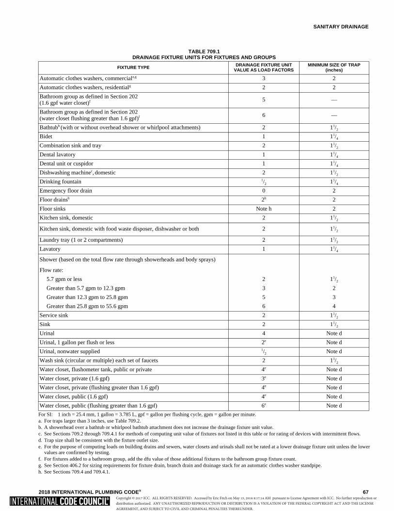
SANITARY DRAINAGE
2018 INTERNATIONAL PLUMBING CODE® 67
TABLE 709.1DRAINAGE FIXTURE UNITS FOR FIXTURES AND GROUPS
For SI: 1 inch = 25.4 mm, 1 gallon = 3.785 L, gpf = gallon per flushing cycle, gpm = gallon per minute. a. For traps larger than 3 inches, use Table 709.2. b. A showerhead over a bathtub or whirlpool bathtub attachment does not increase the drainage fixture unit value. c. See Sections 709.2 through 709.4.1 for methods of computing unit value of fixtures not listed in this table or for rating of devices with intermittent flows. d. Trap size shall be consistent with the fixture outlet size. e. For the purpose of computing loads on building drains and sewers, water closets and urinals shall not be rated at a lower drainage fixture unit unless the lower
values are confirmed by testing. f. For fixtures added to a bathroom group, add the dfu value of those additional fixtures to the bathroom group fixture count. g. See Section 406.2 for sizing requirements for fixture drain, branch drain and drainage stack for an automatic clothes washer standpipe. h. See Sections 709.4 and 709.4.1.
FIXTURE TYPE DRAINAGE FIXTURE UNIT VALUE AS LOAD FACTORS
MINIMUM SIZE OF TRAP(inches)
Automatic clothes washers, commerciala,g 3 2
Automatic clothes washers, residentialg 2 2
Bathroom group as defined in Section 202 (1.6 gpf water closet)f
5 —
Bathroom group as defined in Section 202 (water closet flushing greater than 1.6 gpf)f
6 —
Bathtubb (with or without overhead shower or whirlpool attachments) 2 11/2
Bidet 1 11/4
Combination sink and tray 2 11/2
Dental lavatory 1 11/4
Dental unit or cuspidor 1 11/4
Dishwashing machinec, domestic 2 11/2
Drinking fountain 1/2 11/4
Emergency floor drain 0 2
Floor drainsh 2h 2
Floor sinks Note h 2
Kitchen sink, domestic 2 11/2
Kitchen sink, domestic with food waste disposer, dishwasher or both 2 11/2
Laundry tray (1 or 2 compartments) 2 11/2
Lavatory 1 11/4
Shower (based on the total flow rate through showerheads and body sprays)
Flow rate:
5.7 gpm or less 2 11/2
Greater than 5.7 gpm to 12.3 gpm 3 2
Greater than 12.3 gpm to 25.8 gpm 5 3
Greater than 25.8 gpm to 55.6 gpm 6 4
Service sink 2 11/2
Sink 2 11/2
Urinal 4 Note d
Urinal, 1 gallon per flush or less 2e Note d
Urinal, nonwater supplied 1/2 Note d
Wash sink (circular or multiple) each set of faucets 2 11/2
Water closet, flushometer tank, public or private 4e Note d
Water closet, private (1.6 gpf) 3e Note d
Water closet, private (flushing greater than 1.6 gpf) 4e Note d
Water closet, public (1.6 gpf) 4e Note d
Water closet, public (flushing greater than 1.6 gpf) 6e Note d
Copyright © 2017 ICC. ALL RIGHTS RESERVED. Accessed by Eric Fitch on May 15, 2018 8:17:14 AM pursuant to License Agreement with ICC. No further reproduction ordistribution authorized. ANY UNAUTHORIZED REPRODUCTION OR DISTRIBUTION IS A VIOLATION OF THE FEDERAL COPYRIGHT ACT AND THE LICENSEAGREEMENT, AND SUBJECT TO CIVIL AND CRIMINAL PENALTIES THEREUNDER.
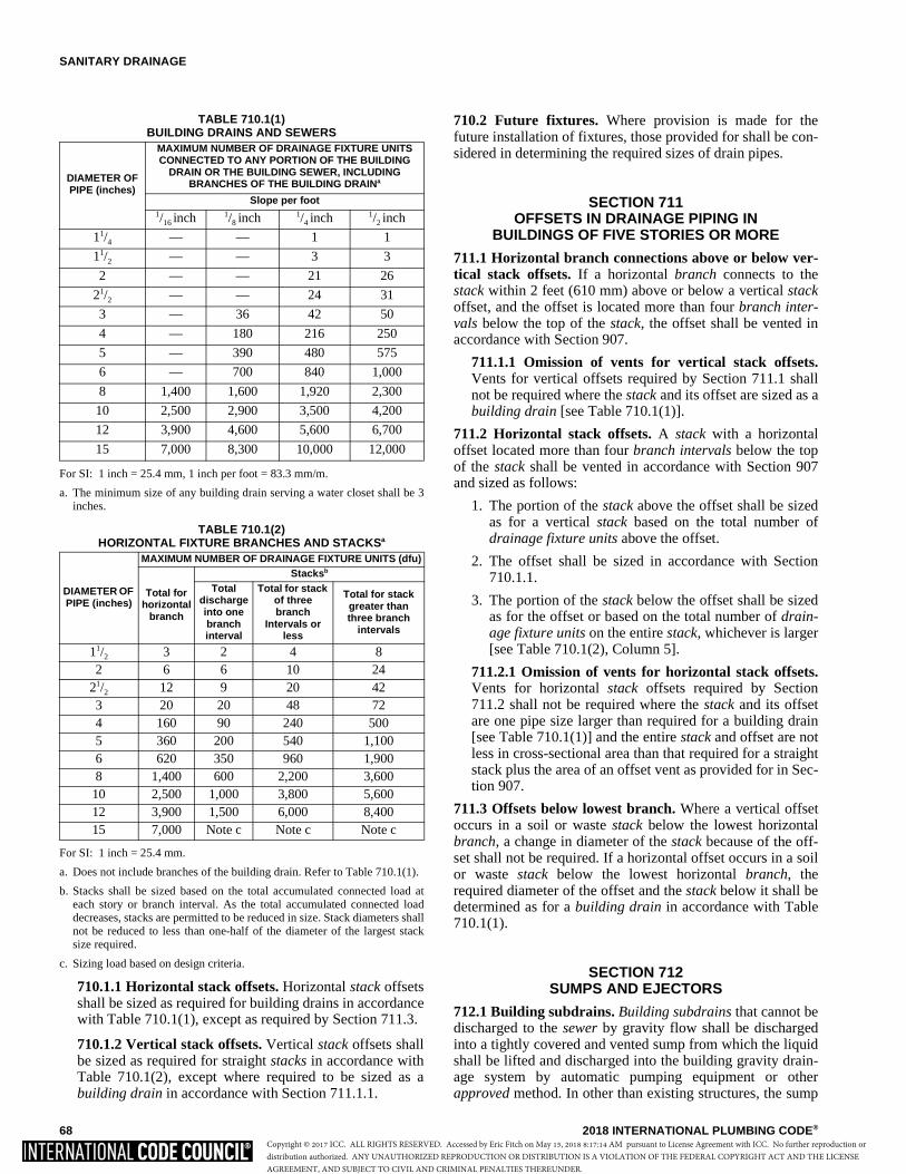
SANITARY DRAINAGE
68 2018 INTERNATIONAL PLUMBING CODE®
TABLE 710.1(1)BUILDING DRAINS AND SEWERS
For SI: 1 inch = 25.4 mm, 1 inch per foot = 83.3 mm/m.
a. The minimum size of any building drain serving a water closet shall be 3inches.
TABLE 710.1(2) HORIZONTAL FIXTURE BRANCHES AND STACKSa
For SI: 1 inch = 25.4 mm.
a. Does not include branches of the building drain. Refer to Table 710.1(1).
b. Stacks shall be sized based on the total accumulated connected load ateach story or branch interval. As the total accumulated connected loaddecreases, stacks are permitted to be reduced in size. Stack diameters shallnot be reduced to less than one-half of the diameter of the largest stacksize required.
c. Sizing load based on design criteria.
710.1.1 Horizontal stack offsets. Horizontal stack offsetsshall be sized as required for building drains in accordancewith Table 710.1(1), except as required by Section 711.3.
710.1.2 Vertical stack offsets. Vertical stack offsets shallbe sized as required for straight stacks in accordance withTable 710.1(2), except where required to be sized as abuilding drain in accordance with Section 711.1.1.
710.2 Future fixtures. Where provision is made for thefuture installation of fixtures, those provided for shall be con-sidered in determining the required sizes of drain pipes.
SECTION 711OFFSETS IN DRAINAGE PIPING IN
BUILDINGS OF FIVE STORIES OR MORE
711.1 Horizontal branch connections above or below ver-tical stack offsets. If a horizontal branch connects to thestack within 2 feet (610 mm) above or below a vertical stackoffset, and the offset is located more than four branch inter-vals below the top of the stack, the offset shall be vented inaccordance with Section 907.
711.1.1 Omission of vents for vertical stack offsets.Vents for vertical offsets required by Section 711.1 shallnot be required where the stack and its offset are sized as abuilding drain [see Table 710.1(1)].
711.2 Horizontal stack offsets. A stack with a horizontaloffset located more than four branch intervals below the topof the stack shall be vented in accordance with Section 907and sized as follows:
1. The portion of the stack above the offset shall be sizedas for a vertical stack based on the total number ofdrainage fixture units above the offset.
2. The offset shall be sized in accordance with Section710.1.1.
3. The portion of the stack below the offset shall be sizedas for the offset or based on the total number of drain-age fixture units on the entire stack, whichever is larger[see Table 710.1(2), Column 5].
711.2.1 Omission of vents for horizontal stack offsets.Vents for horizontal stack offsets required by Section711.2 shall not be required where the stack and its offsetare one pipe size larger than required for a building drain[see Table 710.1(1)] and the entire stack and offset are notless in cross-sectional area than that required for a straightstack plus the area of an offset vent as provided for in Sec-tion 907.
711.3 Offsets below lowest branch. Where a vertical offsetoccurs in a soil or waste stack below the lowest horizontalbranch, a change in diameter of the stack because of the off-set shall not be required. If a horizontal offset occurs in a soilor waste stack below the lowest horizontal branch, therequired diameter of the offset and the stack below it shall bedetermined as for a building drain in accordance with Table710.1(1).
SECTION 712SUMPS AND EJECTORS
712.1 Building subdrains. Building subdrains that cannot bedischarged to the sewer by gravity flow shall be dischargedinto a tightly covered and vented sump from which the liquidshall be lifted and discharged into the building gravity drain-age system by automatic pumping equipment or otherapproved method. In other than existing structures, the sump
DIAMETER OF PIPE (inches)
MAXIMUM NUMBER OF DRAINAGE FIXTURE UNITS CONNECTED TO ANY PORTION OF THE BUILDING
DRAIN OR THE BUILDING SEWER, INCLUDING BRANCHES OF THE BUILDING DRAINa
Slope per foot1/16 inch 1/8 inch 1/4 inch 1/2 inch
11/4 — — 1 1
11/2 — — 3 3
2 — — 21 26
21/2 — — 24 31
3 — 36 42 50
4 — 180 216 250
5 — 390 480 575
6 — 700 840 1,000
8 1,400 1,600 1,920 2,300
10 2,500 2,900 3,500 4,200
12 3,900 4,600 5,600 6,700
15 7,000 8,300 10,000 12,000
DIAMETER OF PIPE (inches)
MAXIMUM NUMBER OF DRAINAGE FIXTURE UNITS (dfu)
Total for horizontal
branch
Stacksb
Total discharge into one branch interval
Total for stack of three branch
Intervals or less
Total for stack greater than three branch
intervals
11/2 3 2 4 82 6 6 10 24
21/2 12 9 20 423 20 20 48 724 160 90 240 5005 360 200 540 1,1006 620 350 960 1,9008 1,400 600 2,200 3,600
10 2,500 1,000 3,800 5,60012 3,900 1,500 6,000 8,40015 7,000 Note c Note c Note c
Copyright © 2017 ICC. ALL RIGHTS RESERVED. Accessed by Eric Fitch on May 15, 2018 8:17:14 AM pursuant to License Agreement with ICC. No further reproduction ordistribution authorized. ANY UNAUTHORIZED REPRODUCTION OR DISTRIBUTION IS A VIOLATION OF THE FEDERAL COPYRIGHT ACT AND THE LICENSEAGREEMENT, AND SUBJECT TO CIVIL AND CRIMINAL PENALTIES THEREUNDER.
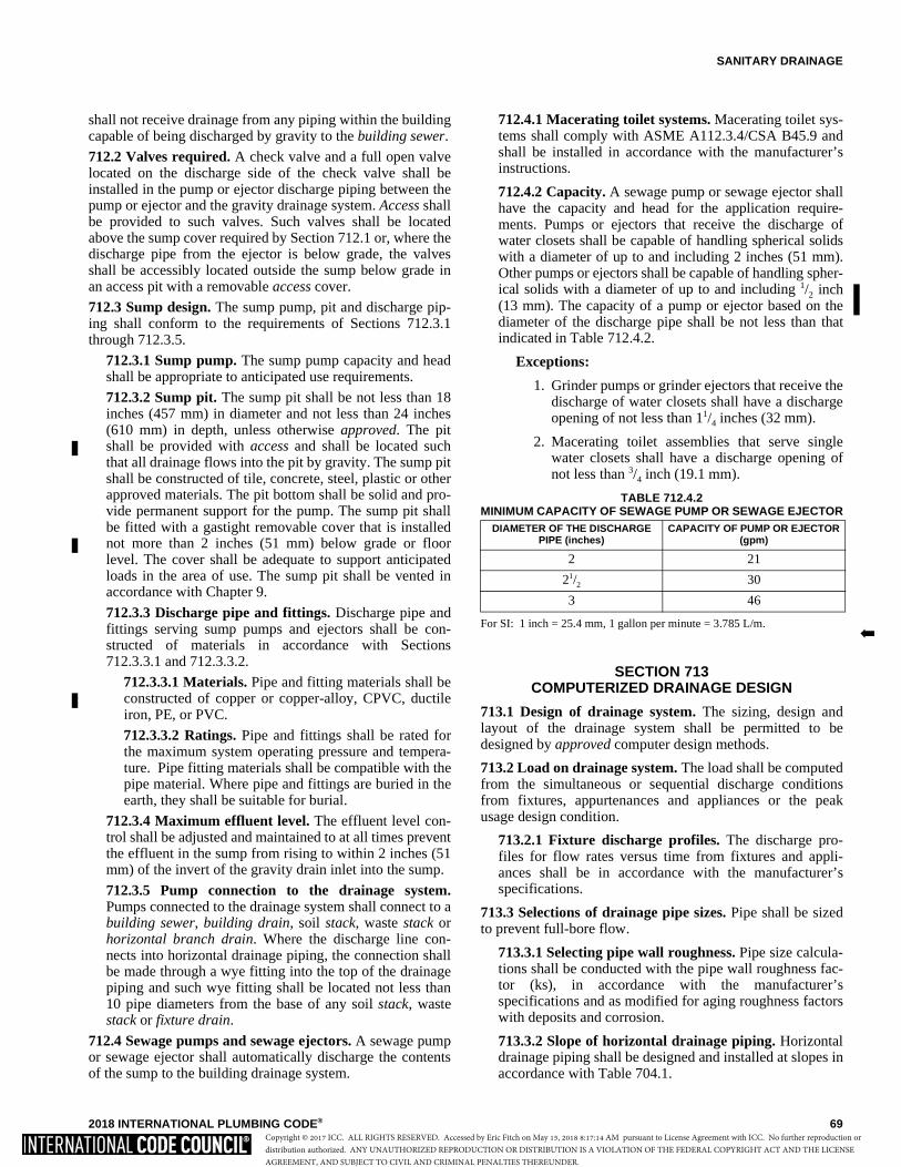
SANITARY DRAINAGE
2018 INTERNATIONAL PLUMBING CODE® 69
shall not receive drainage from any piping within the buildingcapable of being discharged by gravity to the building sewer.
712.2 Valves required. A check valve and a full open valvelocated on the discharge side of the check valve shall beinstalled in the pump or ejector discharge piping between thepump or ejector and the gravity drainage system. Access shallbe provided to such valves. Such valves shall be locatedabove the sump cover required by Section 712.1 or, where thedischarge pipe from the ejector is below grade, the valvesshall be accessibly located outside the sump below grade inan access pit with a removable access cover.
712.3 Sump design. The sump pump, pit and discharge pip-ing shall conform to the requirements of Sections 712.3.1through 712.3.5.
712.3.1 Sump pump. The sump pump capacity and headshall be appropriate to anticipated use requirements.
712.3.2 Sump pit. The sump pit shall be not less than 18inches (457 mm) in diameter and not less than 24 inches(610 mm) in depth, unless otherwise approved. The pitshall be provided with access and shall be located suchthat all drainage flows into the pit by gravity. The sump pitshall be constructed of tile, concrete, steel, plastic or otherapproved materials. The pit bottom shall be solid and pro-vide permanent support for the pump. The sump pit shallbe fitted with a gastight removable cover that is installednot more than 2 inches (51 mm) below grade or floorlevel. The cover shall be adequate to support anticipatedloads in the area of use. The sump pit shall be vented inaccordance with Chapter 9.
712.3.3 Discharge pipe and fittings. Discharge pipe andfittings serving sump pumps and ejectors shall be con-structed of materials in accordance with Sections712.3.3.1 and 712.3.3.2.
712.3.3.1 Materials. Pipe and fitting materials shall beconstructed of copper or copper-alloy, CPVC, ductileiron, PE, or PVC.
712.3.3.2 Ratings. Pipe and fittings shall be rated forthe maximum system operating pressure and tempera-ture. Pipe fitting materials shall be compatible with thepipe material. Where pipe and fittings are buried in theearth, they shall be suitable for burial.
712.3.4 Maximum effluent level. The effluent level con-trol shall be adjusted and maintained to at all times preventthe effluent in the sump from rising to within 2 inches (51mm) of the invert of the gravity drain inlet into the sump.
712.3.5 Pump connection to the drainage system.Pumps connected to the drainage system shall connect to abuilding sewer, building drain, soil stack, waste stack orhorizontal branch drain. Where the discharge line con-nects into horizontal drainage piping, the connection shallbe made through a wye fitting into the top of the drainagepiping and such wye fitting shall be located not less than10 pipe diameters from the base of any soil stack, wastestack or fixture drain.
712.4 Sewage pumps and sewage ejectors. A sewage pumpor sewage ejector shall automatically discharge the contentsof the sump to the building drainage system.
712.4.1 Macerating toilet systems. Macerating toilet sys-tems shall comply with ASME A112.3.4/CSA B45.9 andshall be installed in accordance with the manufacturer’sinstructions.
712.4.2 Capacity. A sewage pump or sewage ejector shallhave the capacity and head for the application require-ments. Pumps or ejectors that receive the discharge ofwater closets shall be capable of handling spherical solidswith a diameter of up to and including 2 inches (51 mm).Other pumps or ejectors shall be capable of handling spher-ical solids with a diameter of up to and including 1/2 inch(13 mm). The capacity of a pump or ejector based on thediameter of the discharge pipe shall be not less than thatindicated in Table 712.4.2.
Exceptions:
1. Grinder pumps or grinder ejectors that receive thedischarge of water closets shall have a dischargeopening of not less than 11/4 inches (32 mm).
2. Macerating toilet assemblies that serve singlewater closets shall have a discharge opening ofnot less than 3/4 inch (19.1 mm).
TABLE 712.4.2 MINIMUM CAPACITY OF SEWAGE PUMP OR SEWAGE EJECTOR
For SI: 1 inch = 25.4 mm, 1 gallon per minute = 3.785 L/m.
SECTION 713COMPUTERIZED DRAINAGE DESIGN
713.1 Design of drainage system. The sizing, design andlayout of the drainage system shall be permitted to bedesigned by approved computer design methods.
713.2 Load on drainage system. The load shall be computedfrom the simultaneous or sequential discharge conditionsfrom fixtures, appurtenances and appliances or the peakusage design condition.
713.2.1 Fixture discharge profiles. The discharge pro-files for flow rates versus time from fixtures and appli-ances shall be in accordance with the manufacturer’sspecifications.
713.3 Selections of drainage pipe sizes. Pipe shall be sizedto prevent full-bore flow.
713.3.1 Selecting pipe wall roughness. Pipe size calcula-tions shall be conducted with the pipe wall roughness fac-tor (ks), in accordance with the manufacturer’sspecifications and as modified for aging roughness factorswith deposits and corrosion.
713.3.2 Slope of horizontal drainage piping. Horizontaldrainage piping shall be designed and installed at slopes inaccordance with Table 704.1.
DIAMETER OF THE DISCHARGE PIPE (inches)
CAPACITY OF PUMP OR EJECTOR (gpm)
2 21
21/2 30
3 46
�
Copyright © 2017 ICC. ALL RIGHTS RESERVED. Accessed by Eric Fitch on May 15, 2018 8:17:14 AM pursuant to License Agreement with ICC. No further reproduction ordistribution authorized. ANY UNAUTHORIZED REPRODUCTION OR DISTRIBUTION IS A VIOLATION OF THE FEDERAL COPYRIGHT ACT AND THE LICENSEAGREEMENT, AND SUBJECT TO CIVIL AND CRIMINAL PENALTIES THEREUNDER.
SANITARY DRAINAGE
70 2018 INTERNATIONAL PLUMBING CODE®
SECTION 714BACKWATER VALVES
714.1 Sewage backflow. Where plumbing fixtures areinstalled on a floor with a finished floor elevation below theelevation of the manhole cover of the next upstream manholein the public sewer, such fixtures shall be protected by abackwater valve installed in the building drain, or horizontalbranch serving such fixtures. Plumbing fixtures installed on afloor with a finished floor elevation above the elevation of themanhole cover of the next upstream manhole in the publicsewer shall not discharge through a backwater valve.
Exception: In existing buildings, fixtures above the eleva-tion of the manhole cover of the next upstream manhole inthe public sewer shall not be prohibited from dischargingthrough a backwater valve.
714.2 Material. Backwater valves shall comply with ASMEA112.14.1, CSA B181.1 or CSA B181.2.
714.3 Location. Backwater valves shall be installed so thataccess is provided to the working parts.
SECTION 715VACUUM DRAINAGE SYSTEMS
715.1 Scope. Vacuum drainage systems shall be in accor-dance with Sections 715.2 through 715.4.
715.2 System design. Vacuum drainage systems shall bedesigned in accordance with the vacuum drainage systemmanufacturer’s instructions. The system layout, includingpiping layout, tank assemblies, vacuum pump assembly andother components necessary for proper function of the systemshall be in accordance with the manufacturer’s instructions.Plans, specifications and other data for such systems shall besubmitted to the code official for review and approval prior toinstallation.
715.2.1 Fixtures. Gravity-type fixtures installed in vac-uum drainage systems shall comply with Chapter 4.
715.2.2 Drainage fixture units. Drainage fixture units forgravity drainage systems that discharge into, or receivedischarge from, vacuum drainage systems shall be basedon the values in this chapter.
715.2.3 Water supply fixture units. Water supply fixtureunits shall be based on the values in Chapter 6 of this code,except that the water supply fixture unit for a vacuum-typewater closet shall be 1.
715.2.4 Traps and cleanouts. Gravity drainage fixturesshall be provided with traps and cleanouts in accordancewith this chapter and Chapter 10.
715.2.5 Materials. Vacuum drainage pipe, fitting andvalve materials shall be in accordance with the vacuumdrainage system manufacturer’s instructions and therequirements of this chapter.
715.3 Testing and demonstrations. After completion of theentire system installation, the system shall be subjected to avacuum test of 19 inches (483 mm) of mercury and shall beoperated to function as required by the code official and themanufacturer of the vacuum drainage system. Recorded proofof all tests shall be submitted to the code official.
715.4 Written instructions. Written instructions for theoperation, maintenance, safety and emergency proceduresshall be provided to the building owner. The code officialshall verify that the building owner is in receipt of suchinstructions.
SECTION 716REPLACEMENT OF UNDERGROUND
BUILDING SEWERS AND BUILDING DRAINS BY PIPE-BURSTING METHODS
716.1 General. This section shall govern the replacement ofexisting building sewer and building drain piping by pipe-bursting methods.
716.2 Applicability. The replacement of building sewer andbuilding drain piping by pipe-bursting methods shall be lim-ited to gravity drainage piping of sizes 6 inches (152 mm) andsmaller. The replacement piping shall be of the same nominalsize as the existing piping.
716.3 Pre-installation inspection. The existing piping sec-tions to be replaced shall be inspected internally by arecorded video camera survey. The survey shall include nota-tions of the position of cleanouts and the depth of connectionsto the existing piping.
716.4 Pipe. The replacement pipe shall be made of high-den-sity polyethylene (HDPE) and shall have a standard dimen-sion ratio (SDR) of 17. The pipe shall be in compliance withASTM F714.
716.5 Pipe fittings. Pipe fittings to be connected to thereplacement pipe shall be made of high-density polyethylene(HDPE) and shall be in compliance with ASTM D2683.
716.6 Cleanouts. Where the existing building sewer or build-ing drain did not have cleanouts meeting the requirements ofthis code, cleanout fittings shall be installed as required bythis code.
716.7 Post-installation inspection. The completed replace-ment piping section shall be inspected internally by arecorded video camera survey. The video survey shall bereviewed and approved by the code official prior to pressuretesting of the replacement piping system.
716.8 Pressure testing. The replacement piping system aswell as the connections to the replacement piping shall betested in accordance with Section 312.
�
Copyright © 2017 ICC. ALL RIGHTS RESERVED. Accessed by Eric Fitch on May 15, 2018 8:17:14 AM pursuant to License Agreement with ICC. No further reproduction ordistribution authorized. ANY UNAUTHORIZED REPRODUCTION OR DISTRIBUTION IS A VIOLATION OF THE FEDERAL COPYRIGHT ACT AND THE LICENSEAGREEMENT, AND SUBJECT TO CIVIL AND CRIMINAL PENALTIES THEREUNDER.
2018 INTERNATIONAL PLUMBING CODE® 71
CHAPTER 8
INDIRECT/SPECIAL WASTE
User note:
About this chapter: There are drainage applications in buildings where a backup of liquid waste in a drainage system could contaminateequipment and appliances. Chapter 8 covers the applications that require an indirect discharge connection to the building’s drainage system.The chapter has provisions for the types of indirect connections and waste receptor configurations.
SECTION 801GENERAL
801.1 Scope. This chapter shall govern matters concerningindirect waste piping and special wastes. This chapter shallfurther control matters concerning food-handling establish-ments, sterilizers, humidifiers, clear-water waste, swimmingpools, methods of providing air breaks or air gaps, and neu-tralizing devices for corrosive wastes.
801.2 Protection. Devices, appurtenances, appliances andapparatus intended to serve some special function, such assterilization, humidification, distillation, processing, cooling,or storage of ice or foods, and that discharge to the drainagesystem, shall be provided with protection against backflow,flooding, fouling, contamination and stoppage of the drain.
SECTION 802INDIRECT WASTES
802.1 Where required. Food-handling equipment, in otherthan dwelling units, clear-water waste, humidifiers, dish-washing machines and utensils, pots, pans and dishwashingsinks shall discharge through an indirect waste pipe as speci-fied in Sections 802.1.1 through 802.1.8. Fixtures notrequired to be indirectly connected by this section and theexception to Section 301.6 shall be directly connected to theplumbing system in accordance with Chapter 7.
802.1.1 Food handling. Equipment and fixtures utilizedfor the storage, preparation and handling of food shall dis-charge through an indirect waste pipe by means of an airgap. Each well of a multiple-compartment sink shall dis-charge independently to a waste receptor.
802.1.2 Floor drains in food storage areas. Floor drainslocated within walk-in refrigerators or freezers in food ser-vice and food establishments shall be indirectly connectedto the sanitary drainage system by means of an air gap.Where a floor drain is located within an area subject tofreezing, the waste line serving the floor drain shall not betrapped and shall indirectly discharge into a waste receptorlocated outside of the area subject to freezing.
Exception: Where protected against backflow by abackwater valve, such floor drains shall be indirectlyconnected to the sanitary drainage system by means ofan air break or an air gap.
802.1.3 Potable clear-water waste. Where devices andequipment, such as sterilizers and relief valves, discharge
potable water to the building drainage system, the dis-charge shall be through an indirect waste pipe by means ofan air gap.
802.1.4 Swimming pools. Where waste water from swim-ming pools, backwash from filters and water from pooldeck drains discharge to the building drainage system, thedischarge shall be through an indirect waste pipe by meansof an air gap.
802.1.5 Nonpotable clear-water waste. Where devicesand equipment such as process tanks, filters, drips andboilers discharge nonpotable water to the building drain-age system, the discharge shall be through an indirectwaste pipe by means of an air break or an air gap.
802.1.6 Commercial dishwashing machines. The dis-charge from a commercial dishwashing machine shall bethrough an air gap or air break into a waste receptor inaccordance with Section 802.3.
802.1.7 Food utensils, dishes, pots and pans sinks.Sinks, in other than dwelling units, used for the washing,rinsing or sanitizing of utensils, dishes, pots, pans or ser-vice ware used in the preparation, serving or eating of foodshall discharge indirectly through an air gap or an airbreak to the drainage system.
802.2 Material, joints and connections. The materials,joints, connections and methods utilized for the constructionand installation of indirect waste piping systems shall complywith the applicable provisions of Chapter 7.
802.3 Installation. Indirect waste piping shall dischargethrough an air gap or air break into a waste receptor. Wastereceptors shall be trapped and vented and shall connect to thebuilding drainage system. Indirect waste piping that exceeds30 inches (762 mm) in developed length measured horizon-tally, or 54 inches (1372 mm) in total developed length, shallbe trapped.
Exception: Where a waste receptor receives only clear-water waste and does not directly connect to a sanitarydrainage system, the receptor shall not require a trap.
802.3.1 Air gap. The air gap between the indirect wastepipe and the flood level rim of the waste receptor shall benot less than twice the effective opening of the indirectwaste pipe.
802.3.2 Air break. An air break shall be providedbetween the indirect waste pipe and the trap seal of thewaste receptor.
�
**
Copyright © 2017 ICC. ALL RIGHTS RESERVED. Accessed by Eric Fitch on May 15, 2018 8:17:14 AM pursuant to License Agreement with ICC. No further reproduction ordistribution authorized. ANY UNAUTHORIZED REPRODUCTION OR DISTRIBUTION IS A VIOLATION OF THE FEDERAL COPYRIGHT ACT AND THE LICENSEAGREEMENT, AND SUBJECT TO CIVIL AND CRIMINAL PENALTIES THEREUNDER.
INDIRECT/SPECIAL WASTE
72 2018 INTERNATIONAL PLUMBING CODE®
802.4 Waste receptors. For other than hub drains thatreceive only clear-water waste and standpipes, a removablestrainer or basket shall cover the outlet of waste receptors.Waste receptors shall not be installed in concealed spaces.Waste receptors shall not be installed in plenums, crawlspaces, attics, interstitial spaces above ceilings and belowfloors. Ready access shall be provided to waste receptors.
802.4.1 Size of receptors. A waste receptor shall be sizedfor the maximum discharge of all indirect waste pipesserved by the receptor. Receptors shall be installed to pre-vent splashing or flooding.
802.4.2 Hub drains. A hub drain shall be in the form of ahub or a pipe extending not less than 1 inch (25 mm)above a water-impervious floor.
802.4.3 Standpipes. Standpipes shall be individuallytrapped. Standpipes shall extend not less than 18 inches(457 mm) but not greater than 42 inches (1066 mm) abovethe trap weir. Access shall be provided to standpipes anddrains for rodding.
802.4.3.1 Connection of laundry tray to standpipe.As an alternative for a laundry tray fixture connectingdirectly to a drainage system, a laundry tray waste linewithout a fixture trap shall connect to a standpipe for anautomatic clothes washer drain. The standpipe shallextend not less than 30 inches (732 mm) above the weirof the standpipe trap and shall extend above the floodlevel rim of the laundry tray. The outlet of the laundrytray shall not be greater than 30 inches (762 mm) hori-zontal distance from the side of the standpipe.
SECTION 803SPECIAL WASTES
803.1 Neutralizing device required for corrosive wastes.Corrosive liquids, spent acids or other harmful chemicals thatdestroy or injure a drain, sewer, soil or waste pipe, or createnoxious or toxic fumes or interfere with sewage treatmentprocesses shall not be discharged into the plumbing systemwithout being thoroughly diluted, neutralized or treated bypassing through an approved dilution or neutralizing device.Such devices shall be automatically provided with a suffi-cient supply of diluting water or neutralizing medium so as tomake the contents noninjurious before discharge into thedrainage system. The nature of the corrosive or harmful wasteand the method of its treatment or dilution shall be approvedprior to installation.
803.2 System design. A chemical drainage and vent systemshall be designed and installed in accordance with this code.Chemical drainage and vent systems shall be completely sep-arated from the sanitary systems. Chemical waste shall notdischarge to a sanitary drainage system until such waste hasbeen treated in accordance with Section 803.1.
*
Copyright © 2017 ICC. ALL RIGHTS RESERVED. Accessed by Eric Fitch on May 15, 2018 8:17:14 AM pursuant to License Agreement with ICC. No further reproduction ordistribution authorized. ANY UNAUTHORIZED REPRODUCTION OR DISTRIBUTION IS A VIOLATION OF THE FEDERAL COPYRIGHT ACT AND THE LICENSEAGREEMENT, AND SUBJECT TO CIVIL AND CRIMINAL PENALTIES THEREUNDER.
2018 INTERNATIONAL PLUMBING CODE® 73
CHAPTER 9
VENTS
User note:
About this chapter: Chapter 9 regulates connection locations, various venting system arrangements and the sizing of piping for vent sys-tems. The proper operation of a gravity flow drainage system (Chapter 7) depends on maintaining an air path throughout the system to pre-vent waste and odor “blow back” into fixtures and siphoning of the trap seal in fixture traps (Chapter 10).
SECTION 901 GENERAL
901.1 Scope. The provisions of this chapter shall govern thematerials, design, construction and installation of vent sys-tems.
901.2 Trap seal protection. The plumbing system shall beprovided with a system of vent piping that will permit theadmission or emission of air so that the seal of any fixturetrap shall not be subjected to a pressure differential of morethan 1 inch of water column (249 Pa).
901.2.1 Venting required. Traps and trapped fixturesshall be vented in accordance with one of the ventingmethods specified in this chapter.
901.3 Chemical waste vent systems. The vent system for achemical waste system shall be independent of the sanitaryvent system and shall terminate separately through the roof tothe outdoors or to an air admittance valve that complies withASSE 1049. Air admittance valves for chemical waste sys-tems shall be constructed of materials approved in accor-dance with Section 702.5 and shall be tested for chemicalresistance in accordance with ASTM F1412.
901.4 Use limitations. The plumbing vent system shall notbe utilized for purposes other than the venting of the plumb-ing system.
901.5 Tests. The vent system shall be tested in accordancewith Section 312.
901.6 Engineered systems. Engineered venting systemsshall conform to the provisions of Section 919.
SECTION 902 MATERIALS
902.1 Vents. The materials and methods utilized for the con-struction and installation of venting systems shall complywith the applicable provisions of Section 702.
902.2 Sheet copper. Sheet copper for vent pipe flashingsshall conform to ASTM B152 and shall weigh not less than 8ounces per square foot (2.5 kg/m2).
902.3 Sheet lead. Sheet lead for vent pipe flashings shallweigh not less than 3 pounds per square foot (15 kg/m2) forfield-constructed flashings and not less than 21/2 pounds persquare foot (12 kg/m2) for prefabricated flashings.
SECTION 903 VENT TERMINALS
903.1 Roof extension. Open vent pipes that extend through aroof shall be terminated not less than [NUMBER] inches (mm)above the roof. Where a roof is to be used for assembly or asa promenade, observation deck, sunbathing deck or similarpurposes, open vent pipes shall terminate not less than 7 feet(2134 mm) above the roof.
903.2 Frost closure. Where the 97.5-percent value for out-door design temperature is 0°F (-18°C) or less, vent exten-sions through a roof or wall shall be not less than 3 inches (76mm) in diameter. Any increase in the size of the vent shall bemade not less than 1 foot (305 mm) inside the thermal enve-lope of the building.
903.3 Flashings. The juncture of each vent pipe with the roofline shall be made water tight by an approved flashing.
903.4 Prohibited use. A vent terminal shall not be used forany purpose other than a vent terminal.
903.5 Location of vent terminal. An open vent terminalfrom a drainage system shall not be located directly beneathany door, openable window, or other air intake opening of thebuilding or of an adjacent building, and any such vent termi-nal shall not be within 10 feet (3048 mm) horizontally of suchan opening unless it is 3 feet (914 mm) or more above the topof such opening.
903.6 Extension through the wall. Vent terminals extendingthrough the wall shall terminate at a point not less than 10feet (3048 mm) from a lot line and not less than 10 feet (3048mm) above average ground level. Vent terminals shall notterminate under the overhang of a structure with soffit vents.Side wall vent terminals shall be protected to prevent birds orrodents from entering or blocking the vent opening.
903.7 Extension outside a structure. In climates where the97.5-percent value for outside design temperature is less than0°F (-18°C), vent pipes installed on the exterior of the struc-ture shall be protected against freezing by insulation, heat orboth.
SECTION 904 OUTDOOR VENT EXTENSIONS
904.1 Required vent extension. The vent system servingeach building drain shall have not less than one vent pipe thatextends to the outdoors.
Copyright © 2017 ICC. ALL RIGHTS RESERVED. Accessed by Eric Fitch on May 15, 2018 8:17:14 AM pursuant to License Agreement with ICC. No further reproduction ordistribution authorized. ANY UNAUTHORIZED REPRODUCTION OR DISTRIBUTION IS A VIOLATION OF THE FEDERAL COPYRIGHT ACT AND THE LICENSEAGREEMENT, AND SUBJECT TO CIVIL AND CRIMINAL PENALTIES THEREUNDER.
VENTS
74 2018 INTERNATIONAL PLUMBING CODE®
904.1.1 Installation. The required vent shall be a dry ventthat connects to the building drain or an extension of adrain that connects to the building drain. Such vent shallnot be an island fixture vent as allowed by Section 916.
904.1.2 Size. The required vent shall be sized in accor-dance with Section 906.2 based on the required size of thebuilding drain.
904.2 Vent stack required. A vent stack shall be required forevery drainage stack that has five branch intervals or more.
Exception: Drainage stacks installed in accordance withSection 913.
904.3 Vent termination. Vent stacks or stack vents shall ter-minate outdoors to the open air or to a stack-type air admit-tance valve in accordance with Section 918.
904.4 Vent connection at base. Vent stacks shall connect tothe base of the drainage stack. The vent stack shall connect ator below the lowest horizontal branch. Where the vent stackconnects to the building drain, the connection shall be locateddownstream of the drainage stack and within a distance of 10times the diameter of the drainage stack.
904.5 Vent headers. Stack vents and vent stacks connectedinto a common vent header at the top of the stacks andextending to the open air at one point shall be sized in accor-dance with the requirements of Section 906.1. The number offixture units shall be the sum of all fixture units on all stacksconnected thereto, and the developed length shall be the lon-gest vent length from the intersection at the base of the mostdistant stack to the vent terminal in the open air, as a directextension of one stack.
SECTION 905 VENT CONNECTIONS AND GRADES
905.1 Connection. Individual, branch and circuit vents shallconnect to a vent stack, stack vent, air admittance valve orextend to the open air.
905.2 Grade. Vent and branch vent pipes shall be so gradedand connected as to drain back to the drainage pipe bygravity.
905.3 Vent connection to drainage system. Every dry ventconnecting to a horizontal drain shall connect above the cen-terline of the horizontal drain pipe.
905.4 Vertical rise of vent. Every dry vent shall rise verti-cally to a point not less than 6 inches (152 mm) above theflood level rim of the highest trap or trapped fixture beingvented.
Exception: Vents for interceptors located outdoors.
905.5 Height above fixtures. A connection between a ventpipe and a vent stack or stack vent shall be made at not lessthan 6 inches (152 mm) above the flood level rim of the high-est fixture served by the vent. Horizontal vent pipes formingbranch vents, relief vents or loop vents shall be located notless than 6 inches (152 mm) above the flood level rim of thehighest fixture served.
905.6 Vent for future fixtures. Where the drainage pipinghas been roughed-in for future fixtures, a rough-in connectionfor a vent shall be installed. The vent size shall be not lessthan one-half the diameter of the rough-in drain to be served.The vent rough-in shall connect to the vent system, or shall bevented by other means as provided for in this chapter. Theconnection shall be identified to indicate that it is a vent.
SECTION 906 VENT PIPE SIZING
906.1 Size of stack vents and vent stacks. The minimumrequired diameter of stack vents and vent stacks shall bedetermined from the developed length and the total of drain-age fixture units connected thereto in accordance with Table906.1, but in no case shall the diameter be less than one-halfthe diameter of the drain served or less than 11/4 inches (32mm).
906.2 Vents other than stack vents or vent stacks. Thediameter of individual vents, branch vents, circuit vents andrelief vents shall be not less than one-half the required diame-ter of the drain served. The required size of the drain shall bedetermined in accordance with Table 710.1(2). Vent pipesshall be not less than 11/4 inches (32 mm) in diameter. Ventsexceeding 40 feet (12 192 mm) in developed length shall beincreased by one nominal pipe size for the entire developedlength of the vent pipe. Relief vents for soil and waste stacksin buildings having more than 10 branch intervals shall besized in accordance with Section 908.2.
906.3 Developed length. The developed length of individual,branch, circuit and relief vents shall be measured from thefarthest point of vent connection to the drainage system to thepoint of connection to the vent stack, stack vent or termina-tion outside of the building.
906.4 Multiple branch vents. Where multiple branch ventsare connected to a common branch vent, the common branchvent shall be sized in accordance with this section based onthe size of the common horizontal drainage branch that is orwould be required to serve the total drainage fixture unit loadbeing vented.
906.5 Sump vents. Sump vent sizes shall be determined inaccordance with Sections 906.5.1 and 906.5.2.
906.5.1 Sewage pumps and sewage ejectors other thanpneumatic. Drainage piping below sewer level shall bevented in the same manner as that of a gravity system.Building sump vent sizes for sumps with sewage pumps orsewage ejectors, other than pneumatic, shall be determinedin accordance with Table 906.5.1.
906.5.2 Pneumatic sewage ejectors. The air pressurerelief pipe from a pneumatic sewage ejector shall be con-nected to an independent vent stack terminating asrequired for vent extensions through the roof. The reliefpipe shall be sized to relieve air pressure inside the ejectorto atmospheric pressure, but shall be not less than 11/4
inches (32 mm) in size.
Copyright © 2017 ICC. ALL RIGHTS RESERVED. Accessed by Eric Fitch on May 15, 2018 8:17:14 AM pursuant to License Agreement with ICC. No further reproduction ordistribution authorized. ANY UNAUTHORIZED REPRODUCTION OR DISTRIBUTION IS A VIOLATION OF THE FEDERAL COPYRIGHT ACT AND THE LICENSEAGREEMENT, AND SUBJECT TO CIVIL AND CRIMINAL PENALTIES THEREUNDER.
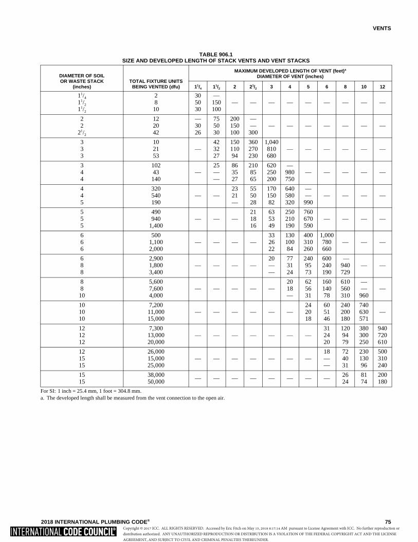
VENTS
2018 INTERNATIONAL PLUMBING CODE® 75
TABLE 906.1SIZE AND DEVELOPED LENGTH OF STACK VENTS AND VENT STACKS
For SI: 1 inch = 25.4 mm, 1 foot = 304.8 mm.a. The developed length shall be measured from the vent connection to the open air.
DIAMETER OF SOIL OR WASTE STACK
(inches) TOTAL FIXTURE UNITS
BEING VENTED (dfu)
MAXIMUM DEVELOPED LENGTH OF VENT (feet)a
DIAMETER OF VENT (inches)
11/4 11/2 2 21/2 3 4 5 6 8 10 12
11/4
11/2
11/2
28
10
305030
—150100
— — — — — — — — —
22
21/2
122042
—3026
755030
200150100
——
300— — — — — — —
333
102153
—423227
15011094
360270230
1,040810680
— — — — — —
344
10243
140—
25——
863527
2108565
620250200
—980750
— — — — —
445
320540190
— —2321—
555028
17015082
640580320
——990
— — — —
555
490940
1,400— — —
211816
635349
250210190
760670590
— — — —
666
5001,1002,000
— — — —332622
13010084
400310260
1,000780660
— — —
688
2,9001,8003,400
— — — —20——
773124
2409573
600240190
— 940729
— —
88
10
5,6007,6004,000
— — — — —2018—
625631
16014078
610560310
——
960—
101010
7,20011,00015,000
— — — — — —242018
605146
240200180
740630571
—
121212
7,30013,00020,000
— — — — — — —312420
1209479
380300250
940720610
121515
26,00015,00025,000
— — — — — — —18——
724031
23013096
500310240
1515
38,00050,000
— — — — — — — — 2624
8174
200180
Copyright © 2017 ICC. ALL RIGHTS RESERVED. Accessed by Eric Fitch on May 15, 2018 8:17:14 AM pursuant to License Agreement with ICC. No further reproduction ordistribution authorized. ANY UNAUTHORIZED REPRODUCTION OR DISTRIBUTION IS A VIOLATION OF THE FEDERAL COPYRIGHT ACT AND THE LICENSEAGREEMENT, AND SUBJECT TO CIVIL AND CRIMINAL PENALTIES THEREUNDER.
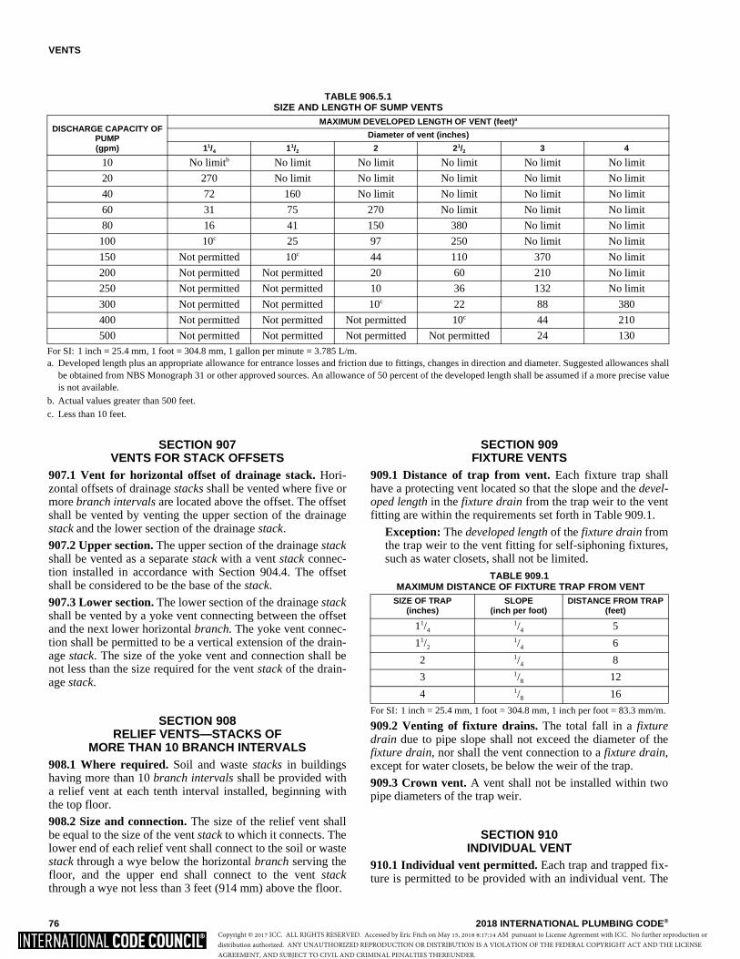
VENTS
76 2018 INTERNATIONAL PLUMBING CODE®
SECTION 907 VENTS FOR STACK OFFSETS
907.1 Vent for horizontal offset of drainage stack. Hori-zontal offsets of drainage stacks shall be vented where five ormore branch intervals are located above the offset. The offsetshall be vented by venting the upper section of the drainagestack and the lower section of the drainage stack.
907.2 Upper section. The upper section of the drainage stackshall be vented as a separate stack with a vent stack connec-tion installed in accordance with Section 904.4. The offsetshall be considered to be the base of the stack.
907.3 Lower section. The lower section of the drainage stackshall be vented by a yoke vent connecting between the offsetand the next lower horizontal branch. The yoke vent connec-tion shall be permitted to be a vertical extension of the drain-age stack. The size of the yoke vent and connection shall benot less than the size required for the vent stack of the drain-age stack.
SECTION 908 RELIEF VENTS—STACKS OF
MORE THAN 10 BRANCH INTERVALS908.1 Where required. Soil and waste stacks in buildingshaving more than 10 branch intervals shall be provided witha relief vent at each tenth interval installed, beginning withthe top floor.
908.2 Size and connection. The size of the relief vent shallbe equal to the size of the vent stack to which it connects. Thelower end of each relief vent shall connect to the soil or wastestack through a wye below the horizontal branch serving thefloor, and the upper end shall connect to the vent stackthrough a wye not less than 3 feet (914 mm) above the floor.
SECTION 909 FIXTURE VENTS
909.1 Distance of trap from vent. Each fixture trap shallhave a protecting vent located so that the slope and the devel-oped length in the fixture drain from the trap weir to the ventfitting are within the requirements set forth in Table 909.1.
Exception: The developed length of the fixture drain fromthe trap weir to the vent fitting for self-siphoning fixtures,such as water closets, shall not be limited.
TABLE 909.1 MAXIMUM DISTANCE OF FIXTURE TRAP FROM VENT
For SI: 1 inch = 25.4 mm, 1 foot = 304.8 mm, 1 inch per foot = 83.3 mm/m.
909.2 Venting of fixture drains. The total fall in a fixturedrain due to pipe slope shall not exceed the diameter of thefixture drain, nor shall the vent connection to a fixture drain,except for water closets, be below the weir of the trap.
909.3 Crown vent. A vent shall not be installed within twopipe diameters of the trap weir.
SECTION 910 INDIVIDUAL VENT
910.1 Individual vent permitted. Each trap and trapped fix-ture is permitted to be provided with an individual vent. The
SIZE OF TRAP(inches)
SLOPE (inch per foot)
DISTANCE FROM TRAP (feet)
11/41/4 5
11/21/4 6
2 1/4 8
3 1/8 12
4 1/8 16
TABLE 906.5.1 SIZE AND LENGTH OF SUMP VENTS
For SI: 1 inch = 25.4 mm, 1 foot = 304.8 mm, 1 gallon per minute = 3.785 L/m.a. Developed length plus an appropriate allowance for entrance losses and friction due to fittings, changes in direction and diameter. Suggested allowances shall
be obtained from NBS Monograph 31 or other approved sources. An allowance of 50 percent of the developed length shall be assumed if a more precise valueis not available.
b. Actual values greater than 500 feet.c. Less than 10 feet.
DISCHARGE CAPACITY OF PUMP (gpm)
MAXIMUM DEVELOPED LENGTH OF VENT (feet)a
Diameter of vent (inches)
11/4 11/2 2 21/2 3 4
10 No limitb No limit No limit No limit No limit No limit
20 270 No limit No limit No limit No limit No limit
40 72 160 No limit No limit No limit No limit
60 31 75 270 No limit No limit No limit
80 16 41 150 380 No limit No limit
100 10c 25 97 250 No limit No limit
150 Not permitted 10c 44 110 370 No limit
200 Not permitted Not permitted 20 60 210 No limit
250 Not permitted Not permitted 10 36 132 No limit
300 Not permitted Not permitted 10c 22 88 380
400 Not permitted Not permitted Not permitted 10c 44 210
500 Not permitted Not permitted Not permitted Not permitted 24 130
Copyright © 2017 ICC. ALL RIGHTS RESERVED. Accessed by Eric Fitch on May 15, 2018 8:17:14 AM pursuant to License Agreement with ICC. No further reproduction ordistribution authorized. ANY UNAUTHORIZED REPRODUCTION OR DISTRIBUTION IS A VIOLATION OF THE FEDERAL COPYRIGHT ACT AND THE LICENSEAGREEMENT, AND SUBJECT TO CIVIL AND CRIMINAL PENALTIES THEREUNDER.
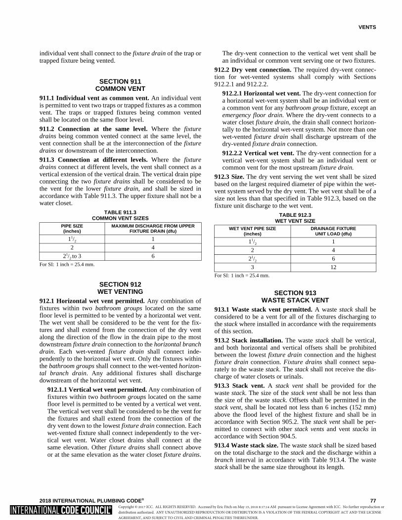
VENTS
2018 INTERNATIONAL PLUMBING CODE® 77
individual vent shall connect to the fixture drain of the trap ortrapped fixture being vented.
SECTION 911 COMMON VENT
911.1 Individual vent as common vent. An individual ventis permitted to vent two traps or trapped fixtures as a commonvent. The traps or trapped fixtures being common ventedshall be located on the same floor level.
911.2 Connection at the same level. Where the fixturedrains being common vented connect at the same level, thevent connection shall be at the interconnection of the fixturedrains or downstream of the interconnection.
911.3 Connection at different levels. Where the fixturedrains connect at different levels, the vent shall connect as avertical extension of the vertical drain. The vertical drain pipeconnecting the two fixture drains shall be considered to bethe vent for the lower fixture drain, and shall be sized inaccordance with Table 911.3. The upper fixture shall not be awater closet.
TABLE 911.3 COMMON VENT SIZES
For SI: 1 inch = 25.4 mm.
SECTION 912 WET VENTING
912.1 Horizontal wet vent permitted. Any combination offixtures within two bathroom groups located on the samefloor level is permitted to be vented by a horizontal wet vent.The wet vent shall be considered to be the vent for the fix-tures and shall extend from the connection of the dry ventalong the direction of the flow in the drain pipe to the mostdownstream fixture drain connection to the horizontal branchdrain. Each wet-vented fixture drain shall connect inde-pendently to the horizontal wet vent. Only the fixtures withinthe bathroom groups shall connect to the wet-vented horizon-tal branch drain. Any additional fixtures shall dischargedownstream of the horizontal wet vent.
912.1.1 Vertical wet vent permitted. Any combination offixtures within two bathroom groups located on the samefloor level is permitted to be vented by a vertical wet vent.The vertical wet vent shall be considered to be the vent forthe fixtures and shall extend from the connection of thedry vent down to the lowest fixture drain connection. Eachwet-vented fixture shall connect independently to the ver-tical wet vent. Water closet drains shall connect at thesame elevation. Other fixture drains shall connect aboveor at the same elevation as the water closet fixture drains.
The dry-vent connection to the vertical wet vent shall bean individual or common vent serving one or two fixtures.
912.2 Dry vent connection. The required dry-vent connec-tion for wet-vented systems shall comply with Sections912.2.1 and 912.2.2.
912.2.1 Horizontal wet vent. The dry-vent connection fora horizontal wet-vent system shall be an individual vent ora common vent for any bathroom group fixture, except anemergency floor drain. Where the dry-vent connects to awater closet fixture drain, the drain shall connect horizon-tally to the horizontal wet-vent system. Not more than onewet-vented fixture drain shall discharge upstream of thedry-vented fixture drain connection.
912.2.2 Vertical wet vent. The dry-vent connection for avertical wet-vent system shall be an individual vent orcommon vent for the most upstream fixture drain.
912.3 Size. The dry vent serving the wet vent shall be sizedbased on the largest required diameter of pipe within the wet-vent system served by the dry vent. The wet vent shall be of asize not less than that specified in Table 912.3, based on thefixture unit discharge to the wet vent.
TABLE 912.3 WET VENT SIZE
For SI: 1 inch = 25.4 mm.
SECTION 913 WASTE STACK VENT
913.1 Waste stack vent permitted. A waste stack shall beconsidered to be a vent for all of the fixtures discharging tothe stack where installed in accordance with the requirementsof this section.
913.2 Stack installation. The waste stack shall be vertical,and both horizontal and vertical offsets shall be prohibitedbetween the lowest fixture drain connection and the highestfixture drain connection. Fixture drains shall connect sepa-rately to the waste stack. The stack shall not receive the dis-charge of water closets or urinals.
913.3 Stack vent. A stack vent shall be provided for thewaste stack. The size of the stack vent shall be not less thanthe size of the waste stack. Offsets shall be permitted in thestack vent, shall be located not less than 6 inches (152 mm)above the flood level of the highest fixture and shall be inaccordance with Section 905.2. The stack vent shall be per-mitted to connect with other stack vents and vent stacks inaccordance with Section 904.5.
913.4 Waste stack size. The waste stack shall be sized basedon the total discharge to the stack and the discharge within abranch interval in accordance with Table 913.4. The wastestack shall be the same size throughout its length.
PIPE SIZE (inches)
MAXIMUM DISCHARGE FROM UPPER FIXTURE DRAIN (dfu)
11/2 1
2 4
21/2 to 3 6
WET VENT PIPE SIZE (inches)
DRAINAGE FIXTUREUNIT LOAD (dfu)
11/2 1
2 4
21/2 6
3 12
Copyright © 2017 ICC. ALL RIGHTS RESERVED. Accessed by Eric Fitch on May 15, 2018 8:17:14 AM pursuant to License Agreement with ICC. No further reproduction ordistribution authorized. ANY UNAUTHORIZED REPRODUCTION OR DISTRIBUTION IS A VIOLATION OF THE FEDERAL COPYRIGHT ACT AND THE LICENSEAGREEMENT, AND SUBJECT TO CIVIL AND CRIMINAL PENALTIES THEREUNDER.
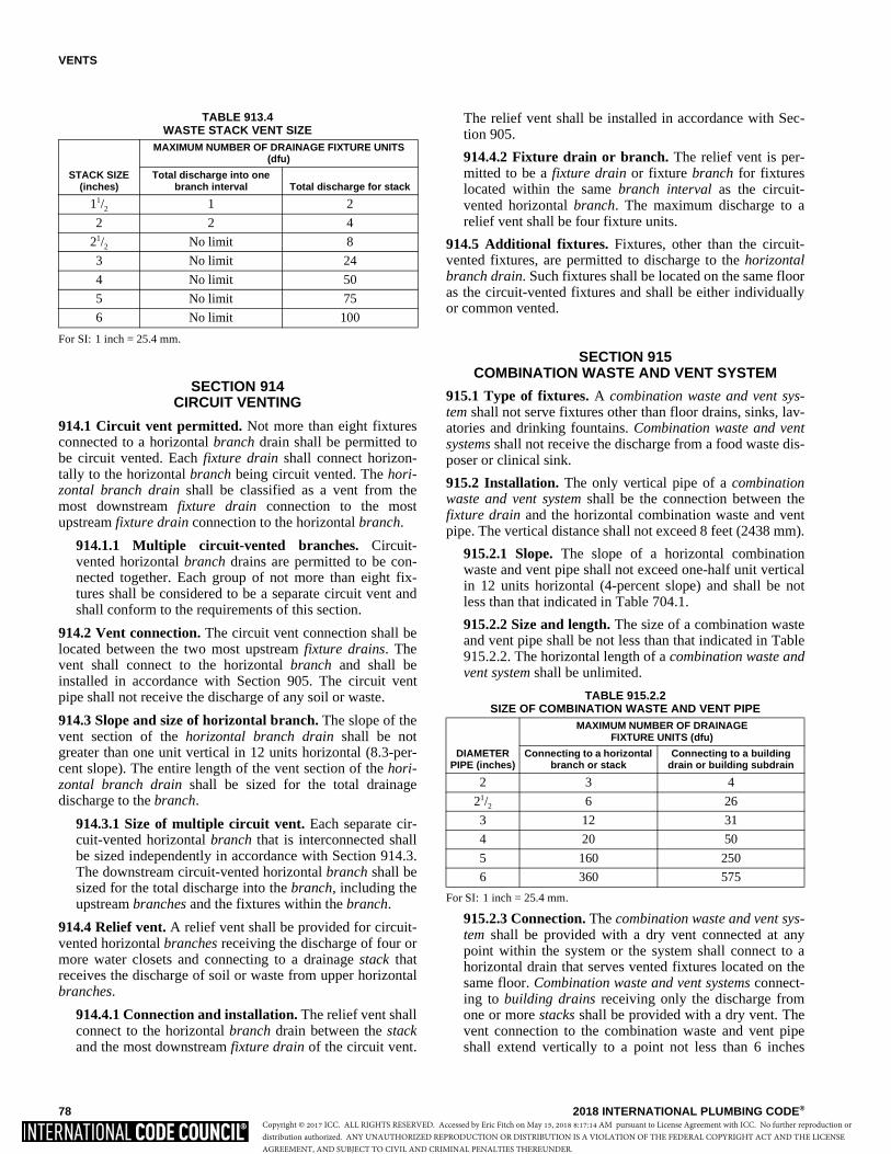
VENTS
78 2018 INTERNATIONAL PLUMBING CODE®
TABLE 913.4 WASTE STACK VENT SIZE
For SI: 1 inch = 25.4 mm.
SECTION 914 CIRCUIT VENTING
914.1 Circuit vent permitted. Not more than eight fixturesconnected to a horizontal branch drain shall be permitted tobe circuit vented. Each fixture drain shall connect horizon-tally to the horizontal branch being circuit vented. The hori-zontal branch drain shall be classified as a vent from themost downstream fixture drain connection to the mostupstream fixture drain connection to the horizontal branch.
914.1.1 Multiple circuit-vented branches. Circuit-vented horizontal branch drains are permitted to be con-nected together. Each group of not more than eight fix-tures shall be considered to be a separate circuit vent andshall conform to the requirements of this section.
914.2 Vent connection. The circuit vent connection shall belocated between the two most upstream fixture drains. Thevent shall connect to the horizontal branch and shall beinstalled in accordance with Section 905. The circuit ventpipe shall not receive the discharge of any soil or waste.
914.3 Slope and size of horizontal branch. The slope of thevent section of the horizontal branch drain shall be notgreater than one unit vertical in 12 units horizontal (8.3-per-cent slope). The entire length of the vent section of the hori-zontal branch drain shall be sized for the total drainagedischarge to the branch.
914.3.1 Size of multiple circuit vent. Each separate cir-cuit-vented horizontal branch that is interconnected shallbe sized independently in accordance with Section 914.3.The downstream circuit-vented horizontal branch shall besized for the total discharge into the branch, including theupstream branches and the fixtures within the branch.
914.4 Relief vent. A relief vent shall be provided for circuit-vented horizontal branches receiving the discharge of four ormore water closets and connecting to a drainage stack thatreceives the discharge of soil or waste from upper horizontalbranches.
914.4.1 Connection and installation. The relief vent shallconnect to the horizontal branch drain between the stackand the most downstream fixture drain of the circuit vent.
The relief vent shall be installed in accordance with Sec-tion 905.
914.4.2 Fixture drain or branch. The relief vent is per-mitted to be a fixture drain or fixture branch for fixtureslocated within the same branch interval as the circuit-vented horizontal branch. The maximum discharge to arelief vent shall be four fixture units.
914.5 Additional fixtures. Fixtures, other than the circuit-vented fixtures, are permitted to discharge to the horizontalbranch drain. Such fixtures shall be located on the same flooras the circuit-vented fixtures and shall be either individuallyor common vented.
SECTION 915 COMBINATION WASTE AND VENT SYSTEM
915.1 Type of fixtures. A combination waste and vent sys-tem shall not serve fixtures other than floor drains, sinks, lav-atories and drinking fountains. Combination waste and ventsystems shall not receive the discharge from a food waste dis-poser or clinical sink.
915.2 Installation. The only vertical pipe of a combinationwaste and vent system shall be the connection between thefixture drain and the horizontal combination waste and ventpipe. The vertical distance shall not exceed 8 feet (2438 mm).
915.2.1 Slope. The slope of a horizontal combinationwaste and vent pipe shall not exceed one-half unit verticalin 12 units horizontal (4-percent slope) and shall be notless than that indicated in Table 704.1.
915.2.2 Size and length. The size of a combination wasteand vent pipe shall be not less than that indicated in Table915.2.2. The horizontal length of a combination waste andvent system shall be unlimited.
TABLE 915.2.2 SIZE OF COMBINATION WASTE AND VENT PIPE
For SI: 1 inch = 25.4 mm.
915.2.3 Connection. The combination waste and vent sys-tem shall be provided with a dry vent connected at anypoint within the system or the system shall connect to ahorizontal drain that serves vented fixtures located on thesame floor. Combination waste and vent systems connect-ing to building drains receiving only the discharge fromone or more stacks shall be provided with a dry vent. Thevent connection to the combination waste and vent pipeshall extend vertically to a point not less than 6 inches
STACK SIZE (inches)
MAXIMUM NUMBER OF DRAINAGE FIXTURE UNITS (dfu)
Total discharge into one branch interval Total discharge for stack
11/2 1 2
2 2 4
21/2 No limit 8
3 No limit 24
4 No limit 50
5 No limit 75
6 No limit 100
DIAMETER PIPE (inches)
MAXIMUM NUMBER OF DRAINAGE FIXTURE UNITS (dfu)
Connecting to a horizontal branch or stack
Connecting to a building drain or building subdrain
2 3 4
21/2 6 26
3 12 31
4 20 50
5 160 250
6 360 575
Copyright © 2017 ICC. ALL RIGHTS RESERVED. Accessed by Eric Fitch on May 15, 2018 8:17:14 AM pursuant to License Agreement with ICC. No further reproduction ordistribution authorized. ANY UNAUTHORIZED REPRODUCTION OR DISTRIBUTION IS A VIOLATION OF THE FEDERAL COPYRIGHT ACT AND THE LICENSEAGREEMENT, AND SUBJECT TO CIVIL AND CRIMINAL PENALTIES THEREUNDER.
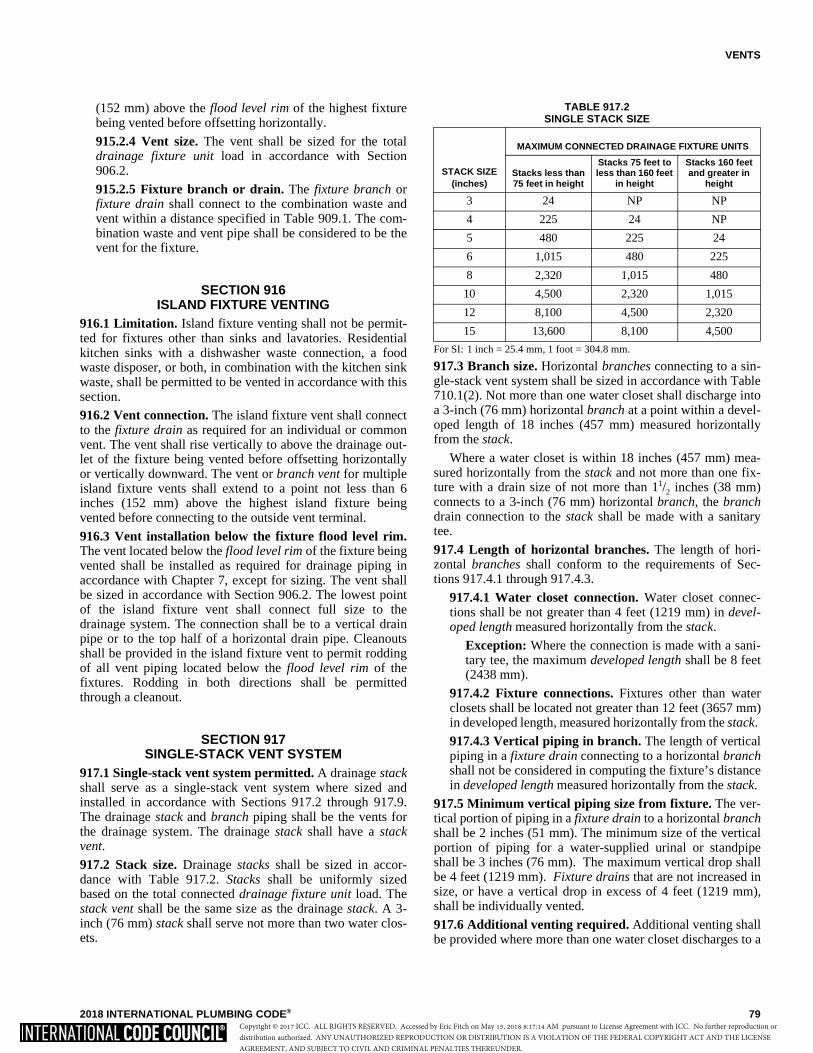
VENTS
2018 INTERNATIONAL PLUMBING CODE® 79
(152 mm) above the flood level rim of the highest fixturebeing vented before offsetting horizontally.
915.2.4 Vent size. The vent shall be sized for the totaldrainage fixture unit load in accordance with Section906.2.
915.2.5 Fixture branch or drain. The fixture branch orfixture drain shall connect to the combination waste andvent within a distance specified in Table 909.1. The com-bination waste and vent pipe shall be considered to be thevent for the fixture.
SECTION 916 ISLAND FIXTURE VENTING
916.1 Limitation. Island fixture venting shall not be permit-ted for fixtures other than sinks and lavatories. Residentialkitchen sinks with a dishwasher waste connection, a foodwaste disposer, or both, in combination with the kitchen sinkwaste, shall be permitted to be vented in accordance with thissection.
916.2 Vent connection. The island fixture vent shall connectto the fixture drain as required for an individual or commonvent. The vent shall rise vertically to above the drainage out-let of the fixture being vented before offsetting horizontallyor vertically downward. The vent or branch vent for multipleisland fixture vents shall extend to a point not less than 6inches (152 mm) above the highest island fixture beingvented before connecting to the outside vent terminal.
916.3 Vent installation below the fixture flood level rim.The vent located below the flood level rim of the fixture beingvented shall be installed as required for drainage piping inaccordance with Chapter 7, except for sizing. The vent shallbe sized in accordance with Section 906.2. The lowest pointof the island fixture vent shall connect full size to thedrainage system. The connection shall be to a vertical drainpipe or to the top half of a horizontal drain pipe. Cleanoutsshall be provided in the island fixture vent to permit roddingof all vent piping located below the flood level rim of thefixtures. Rodding in both directions shall be permittedthrough a cleanout.
SECTION 917 SINGLE-STACK VENT SYSTEM
917.1 Single-stack vent system permitted. A drainage stackshall serve as a single-stack vent system where sized andinstalled in accordance with Sections 917.2 through 917.9.The drainage stack and branch piping shall be the vents forthe drainage system. The drainage stack shall have a stackvent.
917.2 Stack size. Drainage stacks shall be sized in accor-dance with Table 917.2. Stacks shall be uniformly sizedbased on the total connected drainage fixture unit load. Thestack vent shall be the same size as the drainage stack. A 3-inch (76 mm) stack shall serve not more than two water clos-ets.
TABLE 917.2 SINGLE STACK SIZE
For SI: 1 inch = 25.4 mm, 1 foot = 304.8 mm.
917.3 Branch size. Horizontal branches connecting to a sin-gle-stack vent system shall be sized in accordance with Table710.1(2). Not more than one water closet shall discharge intoa 3-inch (76 mm) horizontal branch at a point within a devel-oped length of 18 inches (457 mm) measured horizontallyfrom the stack.
Where a water closet is within 18 inches (457 mm) mea-sured horizontally from the stack and not more than one fix-ture with a drain size of not more than 11/2 inches (38 mm)connects to a 3-inch (76 mm) horizontal branch, the branchdrain connection to the stack shall be made with a sanitarytee.
917.4 Length of horizontal branches. The length of hori-zontal branches shall conform to the requirements of Sec-tions 917.4.1 through 917.4.3.
917.4.1 Water closet connection. Water closet connec-tions shall be not greater than 4 feet (1219 mm) in devel-oped length measured horizontally from the stack.
Exception: Where the connection is made with a sani-tary tee, the maximum developed length shall be 8 feet(2438 mm).
917.4.2 Fixture connections. Fixtures other than waterclosets shall be located not greater than 12 feet (3657 mm)in developed length, measured horizontally from the stack.
917.4.3 Vertical piping in branch. The length of verticalpiping in a fixture drain connecting to a horizontal branchshall not be considered in computing the fixture’s distancein developed length measured horizontally from the stack.
917.5 Minimum vertical piping size from fixture. The ver-tical portion of piping in a fixture drain to a horizontal branchshall be 2 inches (51 mm). The minimum size of the verticalportion of piping for a water-supplied urinal or standpipeshall be 3 inches (76 mm). The maximum vertical drop shallbe 4 feet (1219 mm). Fixture drains that are not increased insize, or have a vertical drop in excess of 4 feet (1219 mm),shall be individually vented.
917.6 Additional venting required. Additional venting shallbe provided where more than one water closet discharges to a
STACK SIZE(inches)
MAXIMUM CONNECTED DRAINAGE FIXTURE UNITS
Stacks less than 75 feet in height
Stacks 75 feet to less than 160 feet
in height
Stacks 160 feet and greater in
height
3 24 NP NP
4 225 24 NP
5 480 225 24
6 1,015 480 225
8 2,320 1,015 480
10 4,500 2,320 1,015
12 8,100 4,500 2,320
15 13,600 8,100 4,500
Copyright © 2017 ICC. ALL RIGHTS RESERVED. Accessed by Eric Fitch on May 15, 2018 8:17:14 AM pursuant to License Agreement with ICC. No further reproduction ordistribution authorized. ANY UNAUTHORIZED REPRODUCTION OR DISTRIBUTION IS A VIOLATION OF THE FEDERAL COPYRIGHT ACT AND THE LICENSEAGREEMENT, AND SUBJECT TO CIVIL AND CRIMINAL PENALTIES THEREUNDER.
VENTS
80 2018 INTERNATIONAL PLUMBING CODE®
horizontal branch and where the distance from a fixture trapto the stack exceeds the limits in Section 917.4. Where addi-tional venting is required, the fixture(s) shall be vented byindividual vents, common vents, wet vents, circuit vents, or acombination waste and vent pipe. The dry vent extensions forthe additional venting shall connect to a branch vent, ventstack, stack vent, air admittance valve, or shall terminate out-doors.
917.7 Stack offsets. Where fixture drains are not connectedbelow a horizontal offset in a stack, a horizontal offset shallnot be required to be vented. Where horizontal branches orfixture drains are connected below a horizontal offset in astack, the offset shall be vented in accordance with Section907. Fixture connections shall not be made to a stack within 2feet (610 mm) above or below a horizontal offset.
917.8 Prohibited lower connections. Stacks greater than 2branch intervals in height shall not receive the discharge ofhorizontal branches on the lower two floors. There shall notbe connections to the stack between the lower two floors and a distance of not less than 10 pipe diameters downstreamfrom the base of the single stack vented system.
917.9 Sizing building drains and sewers. The buildingdrain and building sewer receiving the discharge of a singlestack vent system shall be sized in accordance with Table710.1(1).
SECTION 918 AIR ADMITTANCE VALVES
918.1 General. Vent systems utilizing air admittance valvesshall comply with this section. Stack-type air admittancevalves shall conform to ASSE 1050. Individual and branch-type air admittance valves shall conform to ASSE 1051.
918.2 Installation. The valves shall be installed in accor-dance with the requirements of this section and the manufac-turer’s instructions. Air admittance valves shall be installedafter the DWV testing required by Section 312.2 or 312.3 hasbeen performed.
918.3 Where permitted. Individual, branch and circuit ventsshall be permitted to terminate with a connection to an indi-vidual or branch-type air admittance valve in accordance withSection 918.3.1. Stack vents and vent stacks shall be permit-ted to terminate to stack-type air admittance valves in accor-dance with Section 918.3.2.
918.3.1 Horizontal branches. Individual and branch-typeair admittance valves shall vent only fixtures that are onthe same floor level and connect to a horizontal branchdrain. Where the horizontal branch is located more thanfour branch intervals from the top of the stack, the hori-zontal branch shall be provided with a relief vent that shallconnect to a vent stack or stack vent, or extend outdoors tothe open air. The relief vent shall connect to the horizon-tal branch drain between the stack and the most down-stream fixture drain connected to the horizontal branchdrain. The relief vent shall be sized in accordance withSection 906.2 and installed in accordance with Section905. The relief vent shall be permitted to serve as the ventfor other fixtures.
918.3.2 Stack. Stack-type air admittance valves shall beprohibited from serving as the vent terminal for vent stacksor stack vents that serve drainage stacks having more thansix branch intervals.
918.4 Location. Individual and branch-type air admittancevalves shall be located not less than 4 inches (102 mm) abovethe horizontal branch drain or fixture drain being vented.Stack-type air admittance valves shall be located not less than6 inches (152 mm) above the flood level rim of the highestfixture being vented. The air admittance valve shall belocated within the maximum developed length permitted forthe vent. The air admittance valve shall be installed not lessthan 6 inches (152 mm) above insulation materials.
918.5 Access and ventilation. Access shall be provided to allair admittance valves. Such valves shall be installed in a loca-tion that allows air to enter the valve.
918.6 Size. The air admittance valve shall be rated in accor-dance with the standard for the size of the vent to which thevalve is connected.
918.7 Vent required. Within each plumbing system, not lessthan one stack vent or vent stack shall extend outdoors to theopen air.
918.8 Prohibited installations. Air admittance valves shallnot be installed in nonneutralized special waste systems asdescribed in Chapter 8 except where such valves are in com-pliance with ASSE 1049, are constructed of materialsapproved in accordance with Section 702.5 and are tested forchemical resistance in accordance with ASTM F1412. Airadmittance valves shall not be located in spaces utilized assupply or return air plenums. Air admittance valves shall notbe used to vent sumps or tanks except where the vent systemfor the sump or tank has been designed by an engineer. Airadmittance valves shall not be installed on outdoor vent ter-minals for the sole purpose of reducing clearances to gravityair intakes or mechanical air intakes.
SECTION 919 ENGINEERED VENT SYSTEMS
919.1 General. Engineered vent systems shall comply withthis section and the design, submittal, approval, inspectionand testing requirements of Section 105.3.
919.2 Individual branch fixture and individual fixtureheader vents. The maximum developed length of individualfixture vents to vent branches and vent headers shall be deter-mined in accordance with Table 919.2 for the minimum pipediameters at the indicated vent airflow rates.
The individual vent airflow rate shall be determined inaccordance with the following:
Qh,b = Nn,b Qν (Equation 9-1)
For SI: Qh,b = Nn,b Qν (0.4719 L/s)
where:
Nn,b= Number of fixtures per header (or vent branch) ÷ totalnumber of fixtures connected to vent stack.
Qh,b= Vent branch or vent header airflow rate (cfm).
Qν = Total vent stack airflow rate (cfm).
Copyright © 2017 ICC. ALL RIGHTS RESERVED. Accessed by Eric Fitch on May 15, 2018 8:17:14 AM pursuant to License Agreement with ICC. No further reproduction ordistribution authorized. ANY UNAUTHORIZED REPRODUCTION OR DISTRIBUTION IS A VIOLATION OF THE FEDERAL COPYRIGHT ACT AND THE LICENSEAGREEMENT, AND SUBJECT TO CIVIL AND CRIMINAL PENALTIES THEREUNDER.

VENTS
2018 INTERNATIONAL PLUMBING CODE® 81
Qν (gpm)= 27.8 rs 2/3 (1 – rs) D 8/3
Qν (cfm)= 0.134 Qν (gpm)
where:
D = Drainage stack diameter (inches).
Qw = Design discharge load (gpm).
rs = Waste water flow area to total area.
=
Individual vent airflow rates are obtained by equally dis-tributing Qh,b into one-half the total number of fixtures on thebranch or header for more than two fixtures; for an odd num-
ber of total fixtures, decrease by one; for one fixture, applythe full value of Qh,b.
Individual vent developed length shall be increased by 20percent of the distance from the vent stack to the fixture ventconnection on the vent branch or header.
SECTION 920 COMPUTERIZED VENT DESIGN
920.1 Design of vent system. The sizing, design and layoutof the vent system shall be permitted to be determined byapproved computer program design methods.
920.2 System capacity. The vent system shall be based onthe air capacity requirements of the drainage system under apeak load condition.
Qw
27.8 D8 3⁄
-------------------------
TABLE 919.2 MINIMUM DIAMETER AND MAXIMUM LENGTH OF INDIVIDUAL BRANCH FIXTURE VENTS AND
INDIVIDUAL FIXTURE HEADER VENTS FOR SMOOTH PIPES
For SI: 1 inch = 25.4 mm, 1 cubic foot per minute = 0.4719 L/s, 1 foot = 304.8 mm.
DIAMETER OF VENT PIPE
(inches)
INDIVIDUAL VENT AIRFLOW RATE (cubic feet per minute)
Maximum developed length of vent (feet)
1 2 3 4 5 6 7 8 9 10 11 12 13 14 15 16 17 18 19 201/2 95 25 13 8 5 4 3 2 1 1 1 1 1 1 1 1 1 1 1 13/4 100 88 47 30 20 15 10 9 7 6 5 4 3 3 3 2 2 2 2 1
1 — — 100 94 65 48 37 29 24 20 17 14 12 11 9 8 7 7 6 6
11/4 — — — — — — — 100 87 73 62 53 46 40 36 32 29 26 23 21
11/2 — — — — — — — — — — — 100 96 84 75 65 60 54 49 45
2 — — — — — — — — — — — — — — — — — — — 100
Copyright © 2017 ICC. ALL RIGHTS RESERVED. Accessed by Eric Fitch on May 15, 2018 8:17:14 AM pursuant to License Agreement with ICC. No further reproduction ordistribution authorized. ANY UNAUTHORIZED REPRODUCTION OR DISTRIBUTION IS A VIOLATION OF THE FEDERAL COPYRIGHT ACT AND THE LICENSEAGREEMENT, AND SUBJECT TO CIVIL AND CRIMINAL PENALTIES THEREUNDER.

82 2018 INTERNATIONAL PLUMBING CODE®
Copyright © 2017 ICC. ALL RIGHTS RESERVED. Accessed by Eric Fitch on May 15, 2018 8:17:14 AM pursuant to License Agreement with ICC. No further reproduction ordistribution authorized. ANY UNAUTHORIZED REPRODUCTION OR DISTRIBUTION IS A VIOLATION OF THE FEDERAL COPYRIGHT ACT AND THE LICENSEAGREEMENT, AND SUBJECT TO CIVIL AND CRIMINAL PENALTIES THEREUNDER.
2018 INTERNATIONAL PLUMBING CODE® 83
CHAPTER 10
TRAPS, INTERCEPTORS AND SEPARATORS
User note:
About this chapter: Chapter 10 regulates the design of fixture traps, methods for preventing evaporation of trap seals in traps and therequired locations for interceptors and separators. The trap seal of a trap is an essential feature of a drainage system to prevent odors fromthe drainage piping from entering the building. The discharge of various processes, such as cooking and laundry, creates the need for equip-ment to retain detrimental greases and solids from entering the drainage systems.
SECTION 1001 GENERAL
1001.1 Scope. This chapter shall govern the material andinstallation of traps, interceptors and separators.
SECTION 1002 TRAP REQUIREMENTS
1002.1 Fixture traps. Each plumbing fixture shall be sepa-rately trapped by a liquid-seal trap, except as otherwise per-mitted by this code. The vertical distance from the fixtureoutlet to the trap weir shall not exceed 24 inches (610 mm),and the horizontal distance shall not exceed 30 inches (610mm) measured from the centerline of the fixture outlet to thecenterline of the inlet of the trap. The height of a clotheswasher standpipe above a trap shall conform to Section802.3.3. A fixture shall not be double trapped.
Exceptions:1. This section shall not apply to fixtures with integral
traps.
2. A combination plumbing fixture is permitted to beinstalled on one trap, provided that one compartmentis not more than 6 inches (152 mm) deeper than theother compartment and the waste outlets are notmore than 30 inches (762 mm) apart.
3. A grease interceptor intended to serve as a fixturetrap in accordance with the manufacturer’s installa-tion instructions shall be permitted to serve as thetrap for a single fixture or a combination sink of notmore than three compartments where the verticaldistance from the fixture outlet to the inlet of theinterceptor does not exceed 30 inches (762 mm) andthe developed length of the waste pipe from the mostupstream fixture outlet to the inlet of the interceptordoes not exceed 60 inches (1524 mm).
4. Floor drains in multilevel parking structures that dis-charge to a building storm sewer shall not berequired to be individually trapped. Where floordrains in multilevel parking structures are requiredto discharge to a combined building sewer system,the floor drains shall not be required to be individu-ally trapped provided that they are connected to amain trap in accordance with Section 1103.1.
1002.2 Design of traps. Fixture traps shall be self-scouring.Fixture traps shall not have interior partitions, except wheresuch traps are integral with the fixture or where such traps areconstructed of an approved material that is resistant to corro-sion and degradation. Slip joints shall be made with anapproved elastomeric gasket and shall be installed only onthe trap inlet, trap outlet and within the trap seal.
1002.3 Prohibited traps. The following types of traps areprohibited:
1. Traps that depend on moving parts to maintain the seal.
2. Bell traps.
3. Crown-vented traps.
4. Traps not integral with a fixture and that depend oninterior partitions for the seal, except those traps con-structed of an approved material that is resistant to cor-rosion and degradation.
5. “S” traps.
6. Drum traps.
Exception: Drum traps used as solids interceptorsand drum traps serving chemical waste systems shallnot be prohibited.
1002.4 Trap seals. Each fixture trap shall have a liquid sealof not less than 2 inches (51 mm) and not more than 4 inches(102 mm), or deeper for special designs relating to accessiblefixtures.
1002.4.1 Trap seal protection. Trap seals of emergencyfloor drain traps and trap seals subject to evaporation shallbe protected by one of the methods in Sections 1002.4.1.1through 1002.4.1.4.
1002.4.1.1 Potable water-supplied trap seal primervalve. A potable water-supplied trap seal primer valveshall supply water to the trap. Water-supplied trap sealprimer valves shall conform to ASSE 1018. The dis-charge pipe from the trap seal primer valve shall con-nect to the trap above the trap seal on the inlet side ofthe trap.
1002.4.1.2 Reclaimed or gray water-supplied trapseal primer valve. A reclaimed or gray water-suppliedtrap seal primer valve shall supply water to the trap.Water-supplied trap seal primer valves shall conform toASSE 1018. The quality of reclaimed or gray watersupplied to trap seal primer valves shall be in accor-
Copyright © 2017 ICC. ALL RIGHTS RESERVED. Accessed by Eric Fitch on May 15, 2018 8:17:14 AM pursuant to License Agreement with ICC. No further reproduction ordistribution authorized. ANY UNAUTHORIZED REPRODUCTION OR DISTRIBUTION IS A VIOLATION OF THE FEDERAL COPYRIGHT ACT AND THE LICENSEAGREEMENT, AND SUBJECT TO CIVIL AND CRIMINAL PENALTIES THEREUNDER.
TRAPS, INTERCEPTORS AND SEPARATORS
84 2018 INTERNATIONAL PLUMBING CODE®
dance with the requirements of the manufacturer of thetrap seal primer valve. The discharge pipe from the trapseal primer valve shall connect to the trap above thetrap seal, on the inlet side of the trap.
1002.4.1.3 Waste water-supplied trap primer device.A waste water-supplied trap primer device shall supplywater to the trap. Waste water-supplied trap primerdevices shall conform to ASSE 1044. The dischargepipe from the trap seal primer device shall connect tothe trap above the trap seal on the inlet side of the trap.
1002.4.1.4 Barrier-type trap seal protection device.A barrier-type trap seal protection device shall protectthe floor drain trap seal from evaporation. Barrier-typefloor drain trap seal protection devices shall conform toASSE 1072. The devices shall be installed in accor-dance with the manufacturer’s instructions.
1002.5 Size of fixture traps. Fixture trap size shall be suffi-cient to drain the fixture rapidly and not less than the sizeindicated in Table 709.1. A trap shall not be larger than thedrainage pipe into which the trap discharges.
1002.6 Building traps. Building (house) traps shall be pro-hibited.
1002.7 Trap setting and protection. Traps shall be set levelwith respect to the trap seal and, where necessary, shall beprotected from freezing.
1002.8 Recess for trap connection. A recess provided forconnection of the underground trap, such as one serving abathtub in slab-type construction, shall have sides and a bot-tom of corrosion-resistant, insect- and verminproof construc-tion.
1002.9 Acid-resisting traps. Where a vitrified clay or otherbrittleware, acid-resisting trap is installed underground, suchtrap shall be embedded in concrete extending 6 inches (152mm) beyond the bottom and sides of the trap.
1002.10 Plumbing in mental health centers. In mentalhealth centers, pipes and traps shall not be exposed.
SECTION 1003 INTERCEPTORS AND SEPARATORS
1003.1 Where required. Interceptors and separators shall beprovided to prevent the discharge of oil, grease, sand andother substances harmful or hazardous to the public sewer,the private sewage system or the sewage treatment plant orprocesses.
1003.2 Approval. The size, type and location of each inter-ceptor and of each separator shall be designed and installed inaccordance with the manufacturer’s instructions and therequirements of this section based on the anticipated condi-tions of use. Wastes that do not require treatment or separa-tion shall not be discharged into any interceptor or separator.
1003.3 Grease interceptors. Grease interceptors shall com-ply with the requirements of Sections 1003.3.1 through1003.3.8.
1003.3.1 Grease interceptors and automatic greaseremoval devices required. A grease interceptor or auto-matic grease removal device shall be required to receivethe drainage from fixtures and equipment with grease-laden waste located in food preparation areas, such as inrestaurants, hotel kitchens, hospitals, school kitchens,bars, factory cafeterias and clubs. Fixtures and equipmentshall include pot sinks, prerinse sinks; soup kettles or sim-ilar devices; wok stations; floor drains or sinks into whichkettles are drained; automatic hood wash units and dish-washers without prerinse sinks. Grease interceptors andautomatic grease removal devices shall receive waste onlyfrom fixtures and equipment that allow fats, oils or greaseto be discharged. Where lack of space or other constraintsprevent the installation or replacement of a grease inter-ceptor, one or more grease interceptors shall be permittedto be installed on or above the floor and upstream of anexisting grease interceptor.
1003.3.2 Food waste disposers restriction. A food wastedisposer shall not discharge to a grease interceptor.
1003.3.3 Additives to grease interceptors. Dispensingsystems that dispense interceptor performance additives togrease interceptors shall not be installed except where suchsystems dispense microbes for the enhancement of aerobicbioremediation of grease and other organic material, or forinhibiting growth of pathogenic organisms by anaerobicmethods. Such microbial dispensing systems shall beinstalled only where the grease interceptor manufacturer’sinstructions allow such systems and the systems conform toASME A112.14.6. Systems that discharge emulsifiers,chemicals or enzymes to grease interceptors shall be pro-hibited.
1003.3.4 Grease interceptors and automatic greaseremoval devices not required. A grease interceptor or anautomatic grease removal device shall not be required forindividual dwelling units or any private living quarters.
1003.3.5 Hydromechanical grease interceptors, fats,oils and greases disposal systems and automatic greaseremoval devices. Hydromechanical grease interceptors;fats, oils, and greases disposal systems and automaticgrease removal devices shall be sized in accordance withASME A112.14.3, ASME A112.14.4, ASME A112.14.6,CSA B481.3 or PDI G101. Hydromechanical grease inter-ceptors; fats, oils, and greases disposal systems and auto-matic grease removal devices shall be designed and testedin accordance with ASME A112.14.3, ASME A112.14.4,CSA B481.1, PDI G101 or PDI G102. Hydromechanicalgrease interceptors; fats, oils, and greases disposal systemsand automatic grease removal devices shall be installed inaccordance with the manufacturer’s instructions. Wheremanufacturer’s instructions are not provided, hydrome-chanical grease interceptors; fats, oils, and greases dis-posal systems and automatic grease removal devices shallbe installed in compliance with ASME A112.14.3, ASMEA112.14.4, ASME A112.14.6, CSA B481.3 or PDI G101.
1003.3.5.1 Grease interceptor capacity. Grease inter-ceptors shall have the grease retention capacity indi-cated in Table 1003.3.5.1 for the flow-through ratesindicated.
Copyright © 2017 ICC. ALL RIGHTS RESERVED. Accessed by Eric Fitch on May 15, 2018 8:17:14 AM pursuant to License Agreement with ICC. No further reproduction ordistribution authorized. ANY UNAUTHORIZED REPRODUCTION OR DISTRIBUTION IS A VIOLATION OF THE FEDERAL COPYRIGHT ACT AND THE LICENSEAGREEMENT, AND SUBJECT TO CIVIL AND CRIMINAL PENALTIES THEREUNDER.
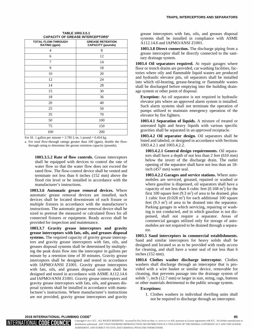
TRAPS, INTERCEPTORS AND SEPARATORS
2018 INTERNATIONAL PLUMBING CODE® 85
1003.3.5.2 Rate of flow controls. Grease interceptorsshall be equipped with devices to control the rate ofwater flow so that the water flow does not exceed therated flow. The flow-control device shall be vented andterminate not less than 6 inches (152 mm) above theflood rim level or be installed in accordance with themanufacturer’s instructions.
1003.3.6 Automatic grease removal devices. Whereautomatic grease removal devices are installed, suchdevices shall be located downstream of each fixture ormultiple fixtures in accordance with the manufacturer’sinstructions. The automatic grease removal device shall besized to pretreat the measured or calculated flows for allconnected fixtures or equipment. Ready access shall beprovided for inspection and maintenance.
1003.3.7 Gravity grease interceptors and gravitygrease interceptors with fats, oils, and greases disposalsystems. The required capacity of gravity grease intercep-tors and gravity grease interceptors with fats, oils, andgreases disposal systems shall be determined by multiply-ing the peak drain flow into the interceptor in gallons perminute by a retention time of 30 minutes. Gravity greaseinterceptors shall be designed and tested in accordancewith IAPMO/ANSI Z1001. Gravity grease interceptorswith fats, oils, and greases disposal systems shall bedesigned and tested in accordance with ASME A112.14.6and IAPMO/ANSI Z1001. Gravity grease interceptors andgravity grease interceptors with fats, oils, and greases dis-posal systems shall be installed in accordance with manu-facturer’s instructions. Where manufacturer’s instructionsare not provided, gravity grease interceptors and gravity
grease interceptors with fats, oils, and greases disposalsystems shall be installed in compliance with ASMEA112.14.6 and IAPMO/ANSI Z1001.
1003.3.8 Direct connection. The discharge piping from agrease interceptor shall be directly connected to the sani-tary drainage system.
1003.4 Oil separators required. At repair garages wherefloor or trench drains are provided, car washing facilities, fac-tories where oily and flammable liquid wastes are producedand hydraulic elevator pits, oil separators shall be installedinto which oil-bearing, grease-bearing or flammable wastesshall be discharged before emptying into the building drain-age system or other point of disposal.
Exception: An oil separator is not required in hydraulicelevator pits where an approved alarm system is installed.Such alarm systems shall not terminate the operation ofpumps utilized to maintain emergency operation of theelevator by fire fighters.
1003.4.1 Separation of liquids. A mixture of treated oruntreated light and heavy liquids with various specificgravities shall be separated in an approved receptacle.
1003.4.2 Oil separator design. Oil separators shall belisted and labeled, or designed in accordance with Sections1003.4.2.1 and 1003.4.2.2.
1003.4.2.1 General design requirements. Oil separa-tors shall have a depth of not less than 2 feet (610 mm)below the invert of the discharge drain. The outletopening of the separator shall have not less than an 18-inch (457 mm) water seal.
1003.4.2.2 Garages and service stations. Where auto-mobiles are serviced, greased, repaired or washed orwhere gasoline is dispensed, oil separators shall have acapacity of not less than 6 cubic feet (0.168 m3) for thefirst 100 square feet (9.3 m2) of area to be drained, plus1 cubic foot (0.028 m3) for each additional 100 squarefeet (9.3 m2) of area to be drained into the separator.Parking garages in which servicing, repairing or wash-ing is not conducted, and in which gasoline is not dis-pensed, shall not require a separator. Areas ofcommercial garages utilized only for storage of auto-mobiles are not required to be drained through a separa-tor.
1003.5 Sand interceptors in commercial establishments.Sand and similar interceptors for heavy solids shall bedesigned and located so as to be provided with ready accessfor cleaning, and shall have a water seal of not less than 6inches (152 mm).
1003.6 Clothes washer discharge interceptor. Clotheswashers shall discharge through an interceptor that is pro-vided with a wire basket or similar device, removable forcleaning, that prevents passage into the drainage system ofsolids 1/2 inch (12.7 mm) or larger in size, string, rags, buttonsor other materials detrimental to the public sewage system.
Exceptions:1. Clothes washers in individual dwelling units shall
not be required to discharge through an interceptor.
TABLE 1003.3.5.1 CAPACITY OF GREASE INTERCEPTORSa
For SI: 1 gallon per minute = 3.785 L/m, 1 pound = 0.454 kg.a. For total flow-through ratings greater than 100 (gpm), double the flow-
through rating to determine the grease retention capacity (pounds).
TOTAL FLOW-THROUGH RATING (gpm)
GREASE RETENTION CAPACITY (pounds)
4 8
6 12
7 14
9 18
10 20
12 24
14 28
15 30
18 36
20 40
25 50
35 70
50 100
75 150
100 200
Copyright © 2017 ICC. ALL RIGHTS RESERVED. Accessed by Eric Fitch on May 15, 2018 8:17:14 AM pursuant to License Agreement with ICC. No further reproduction ordistribution authorized. ANY UNAUTHORIZED REPRODUCTION OR DISTRIBUTION IS A VIOLATION OF THE FEDERAL COPYRIGHT ACT AND THE LICENSEAGREEMENT, AND SUBJECT TO CIVIL AND CRIMINAL PENALTIES THEREUNDER.
TRAPS, INTERCEPTORS AND SEPARATORS
86 2018 INTERNATIONAL PLUMBING CODE®
2. A single clothes washer designed for use in individ-ual dwelling units and installed in a location otherthan an individual dwelling unit shall not berequired to discharge through an interceptor.
1003.7 Bottling establishments. Bottling plants shall dis-charge process wastes into an interceptor that will provide forthe separation of broken glass or other solids before discharg-ing waste into the drainage system.
1003.8 Slaughterhouses. Slaughtering room and dressingroom drains shall be equipped with approved separators. Theseparator shall prevent the discharge into the drainage systemof feathers, entrails and other materials that cause clogging.
1003.9 Venting of interceptors and separators. Intercep-tors and separators shall be designed so as not to become airbound. Interceptors and separators shall be vented in accor-dance with one of the methods in Chapter 9.
1003.10 Access and maintenance of interceptors and sepa-rators. Access shall be provided to each interceptor and sep-arator for service and maintenance. Interceptors andseparators shall be maintained by periodic removal of accu-mulated grease, scum, oil, or other floating substances andsolids deposited in the interceptor or separator.
SECTION 1004 MATERIALS, JOINTS AND CONNECTIONS
1004.1 General. The materials and methods utilized for theconstruction and installation of traps, interceptors and separa-tors shall comply with this chapter and the applicable provi-sions of Chapters 4 and 7. The fittings shall not have ledges,shoulders or reductions capable of retarding or obstructingflow of the piping.
Copyright © 2017 ICC. ALL RIGHTS RESERVED. Accessed by Eric Fitch on May 15, 2018 8:17:14 AM pursuant to License Agreement with ICC. No further reproduction ordistribution authorized. ANY UNAUTHORIZED REPRODUCTION OR DISTRIBUTION IS A VIOLATION OF THE FEDERAL COPYRIGHT ACT AND THE LICENSEAGREEMENT, AND SUBJECT TO CIVIL AND CRIMINAL PENALTIES THEREUNDER.
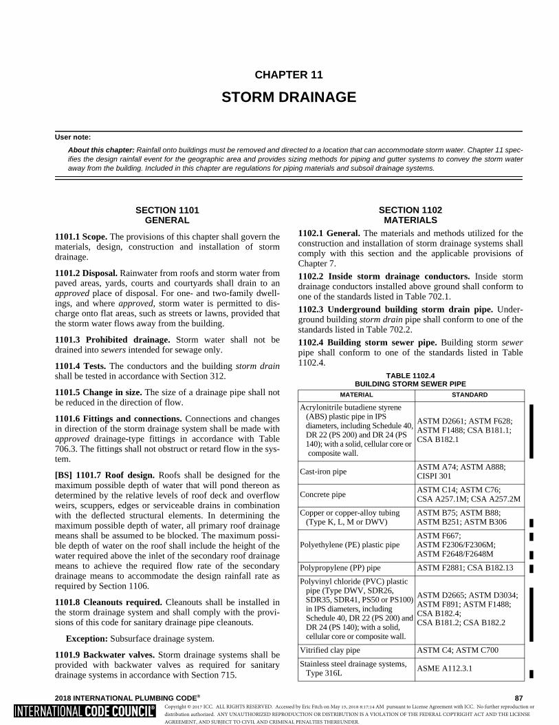
2018 INTERNATIONAL PLUMBING CODE® 87
CHAPTER 11
STORM DRAINAGE
User note:
About this chapter: Rainfall onto buildings must be removed and directed to a location that can accommodate storm water. Chapter 11 spec-ifies the design rainfall event for the geographic area and provides sizing methods for piping and gutter systems to convey the storm wateraway from the building. Included in this chapter are regulations for piping materials and subsoil drainage systems.
SECTION 1101 GENERAL
1101.1 Scope. The provisions of this chapter shall govern thematerials, design, construction and installation of stormdrainage.
1101.2 Disposal. Rainwater from roofs and storm water frompaved areas, yards, courts and courtyards shall drain to anapproved place of disposal. For one- and two-family dwell-ings, and where approved, storm water is permitted to dis-charge onto flat areas, such as streets or lawns, provided thatthe storm water flows away from the building.
1101.3 Prohibited drainage. Storm water shall not bedrained into sewers intended for sewage only.
1101.4 Tests. The conductors and the building storm drainshall be tested in accordance with Section 312.
1101.5 Change in size. The size of a drainage pipe shall notbe reduced in the direction of flow.
1101.6 Fittings and connections. Connections and changesin direction of the storm drainage system shall be made withapproved drainage-type fittings in accordance with Table706.3. The fittings shall not obstruct or retard flow in the sys-tem.
[BS] 1101.7 Roof design. Roofs shall be designed for themaximum possible depth of water that will pond thereon asdetermined by the relative levels of roof deck and overflowweirs, scuppers, edges or serviceable drains in combinationwith the deflected structural elements. In determining themaximum possible depth of water, all primary roof drainagemeans shall be assumed to be blocked. The maximum possi-ble depth of water on the roof shall include the height of thewater required above the inlet of the secondary roof drainagemeans to achieve the required flow rate of the secondarydrainage means to accommodate the design rainfall rate asrequired by Section 1106.
1101.8 Cleanouts required. Cleanouts shall be installed inthe storm drainage system and shall comply with the provi-sions of this code for sanitary drainage pipe cleanouts.
Exception: Subsurface drainage system.
1101.9 Backwater valves. Storm drainage systems shall beprovided with backwater valves as required for sanitarydrainage systems in accordance with Section 715.
SECTION 1102 MATERIALS
1102.1 General. The materials and methods utilized for theconstruction and installation of storm drainage systems shallcomply with this section and the applicable provisions ofChapter 7.
1102.2 Inside storm drainage conductors. Inside stormdrainage conductors installed above ground shall conform toone of the standards listed in Table 702.1.
1102.3 Underground building storm drain pipe. Under-ground building storm drain pipe shall conform to one of thestandards listed in Table 702.2.
1102.4 Building storm sewer pipe. Building storm sewerpipe shall conform to one of the standards listed in Table1102.4.
TABLE 1102.4 BUILDING STORM SEWER PIPE
MATERIAL STANDARD
Acrylonitrile butadiene styrene (ABS) plastic pipe in IPS diameters, including Schedule 40, DR 22 (PS 200) and DR 24 (PS 140); with a solid, cellular core or
composite wall.
ASTM D2661; ASTM F628;ASTM F1488; CSA B181.1;CSA B182.1
Cast-iron pipeASTM A74; ASTM A888;CISPI 301
Concrete pipeASTM C14; ASTM C76;CSA A257.1M; CSA A257.2M
Copper or copper-alloy tubing (Type K, L, M or DWV)
ASTM B75; ASTM B88;ASTM B251; ASTM B306
Polyethylene (PE) plastic pipe ASTM F667;ASTM F2306/F2306M;ASTM F2648/F2648M
Polypropylene (PP) pipe ASTM F2881; CSA B182.13
Polyvinyl chloride (PVC) plastic pipe (Type DWV, SDR26, SDR35, SDR41, PS50 or PS100) in IPS diameters, including Schedule 40, DR 22 (PS 200) and DR 24 (PS 140); with a solid, cellular core or composite wall.
ASTM D2665; ASTM D3034; ASTM F891; ASTM F1488;CSA B182.4;CSA B181.2; CSA B182.2
Vitrified clay pipe ASTM C4; ASTM C700
Stainless steel drainage systems, Type 316L
ASME A112.3.1
Copyright © 2017 ICC. ALL RIGHTS RESERVED. Accessed by Eric Fitch on May 15, 2018 8:17:14 AM pursuant to License Agreement with ICC. No further reproduction ordistribution authorized. ANY UNAUTHORIZED REPRODUCTION OR DISTRIBUTION IS A VIOLATION OF THE FEDERAL COPYRIGHT ACT AND THE LICENSEAGREEMENT, AND SUBJECT TO CIVIL AND CRIMINAL PENALTIES THEREUNDER.
STORM DRAINAGE
88 2018 INTERNATIONAL PLUMBING CODE®
1102.5 Subsoil drain pipe. Subsoil drains shall be open-jointed, horizontally split or perforated pipe conforming toone of the standards listed in Table 1102.5.
1102.6 Roof Drains. Roof drains shall conform to ASMEA112.6.4 or ASME A112.3.1.
TABLE 1102.5 SUBSOIL DRAIN PIPE
1102.7 Fittings. Pipe fittings shall be approved for installa-tion with the piping material installed, and shall conform tothe respective pipe standards or one of the standards listed inTable 1102.7. The fittings shall not have ledges, shoulders or
reductions capable of retarding or obstructing flow in the pip-ing. Threaded drainage pipe fittings shall be of the recesseddrainage type.
SECTION 1103 TRAPS
1103.1 Main trap. Leaders and storm drains connected to acombined sewer shall be trapped. Individual storm watertraps shall be installed on the storm water drain branch serv-ing each conductor, or a single trap shall be installed in themain storm drain just before its connection with the com-bined building sewer or the public sewer. Leaders and stormdrains connected to a building storm sewer shall not berequired to be trapped.
1103.2 Material. Storm water traps shall be of the samematerial as the piping system to which they are attached.
1103.3 Size. Traps for individual conductors shall be thesame size as the horizontal drain to which they are connected.
1103.4 Cleanout. A cleanout shall be installed on the build-ing side of the trap and shall be provided with access.
SECTION 1104 CONDUCTORS AND CONNECTIONS
1104.1 Prohibited use. Conductor pipes shall not be used assoil, waste or vent pipes, and soil, waste or vent pipes shallnot be used as conductors.
1104.2 Floor drains. Floor drains shall not be connected to astorm drain.
SECTION 1105 ROOF DRAINS
1105.1 General. Roof drains shall be installed in accordancewith the manufacturer’s instructions. The inside opening forthe roof drain shall not be obstructed by the roofing mem-brane material.
1105.2 Roof drain flow rate. The published roof drain flowrate, based on the head of water above the roof drain, shall beused to size the storm drainage system in accordance withSection 1106. The flow rate used for sizing the storm drain-age piping shall be based on the maximum anticipated pond-ing at the roof drain.
SECTION 1106 SIZE OF CONDUCTORS, LEADERS
AND STORM DRAINS1106.1 General. The size of the vertical conductors and lead-ers, building storm drains, building storm sewers and anyhorizontal branches of such drains or sewers shall be basedon the 100-year hourly rainfall rate indicated in Figure 1106.1or on other rainfall rates determined from approved localweather data.
MATERIAL STANDARD
Cast-iron pipe ASTM A74; ASTM A888;CISPI 301
Polyethylene (PE) plastic pipe ASTM F405; ASTM F667;CSA B182.1;CSA B182.6; CSA B182.8
Polyvinyl chloride (PVC) Plastic pipe (type sewer pipe,
SDR35, PS25, PS50 or PS100)
ASTM D2729; ASTM D3034, ASTM F891; CSA B182.2; CSA B182.4
Stainless steel drainage systems, Type 316L
ASME A112.3.1
Vitrified clay pipe ASTM C4; ASTM C700
TABLE 1102.7 PIPE FITTINGS
MATERIAL STANDARD
Acrylonitrile butadiene styrene (ABS) plastic
ASTM D2661; ASTM D3311; CSA B181.1
Cast-iron ASME B16.4; ASME B16.12; ASTM A888; CISPI 301;ASTM A74
Coextruded composite ABS and drain DR-PS in PS35, PS50, PS100, PS140, PS200
ASTM D2751
Coextruded composite ABS DWV Schedule 40 IPS pipe (solid or cellular core)
ASTM D2661; ASTM D3311; ASTM F628
Coextruded composite PVC DWV Schedule 40 IPS-DR, PS140, PS200 (solid or cellular core)
ASTM D2665; ASTM D3311; ASTM F891
Coextruded composite PVC sewer and drain DR-PS in PS35, PS50, PS100, PS140, PS200
ASTM D3034
Copper or copper alloy ASME B16.15; ASME B16.18; ASME B16.22; ASME B16.23; ASME B16.26; ASME B16.29
Gray iron and ductile iron AWWA C110/A21.10 Malleable iron ASME B16.3 Plastic, general ASTM F409 Polyethylene (PE) plastic pipe ASTM F2306/F2306M
Polyvinyl chloride (PVC) plastic ASTM D2665; ASTM D3311; ASTM F1866
Steel ASME B16.9; ASME B16.11; ASME B16.28
Stainless steel drainage systems, Type 316L
ASME A112.3.1
Copyright © 2017 ICC. ALL RIGHTS RESERVED. Accessed by Eric Fitch on May 15, 2018 8:17:14 AM pursuant to License Agreement with ICC. No further reproduction ordistribution authorized. ANY UNAUTHORIZED REPRODUCTION OR DISTRIBUTION IS A VIOLATION OF THE FEDERAL COPYRIGHT ACT AND THE LICENSEAGREEMENT, AND SUBJECT TO CIVIL AND CRIMINAL PENALTIES THEREUNDER.
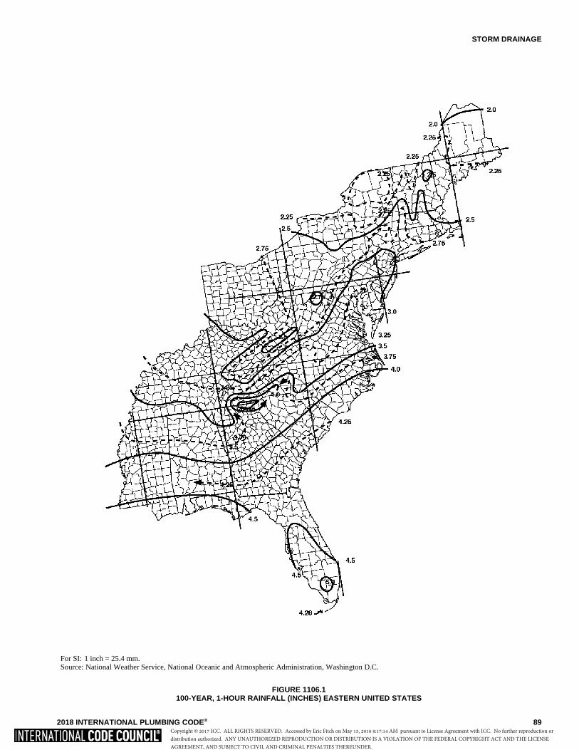
STORM DRAINAGE
2018 INTERNATIONAL PLUMBING CODE® 89
For SI: 1 inch = 25.4 mm.Source: National Weather Service, National Oceanic and Atmospheric Administration, Washington D.C.
FIGURE 1106.1 100-YEAR, 1-HOUR RAINFALL (INCHES) EASTERN UNITED STATES
Copyright © 2017 ICC. ALL RIGHTS RESERVED. Accessed by Eric Fitch on May 15, 2018 8:17:14 AM pursuant to License Agreement with ICC. No further reproduction ordistribution authorized. ANY UNAUTHORIZED REPRODUCTION OR DISTRIBUTION IS A VIOLATION OF THE FEDERAL COPYRIGHT ACT AND THE LICENSEAGREEMENT, AND SUBJECT TO CIVIL AND CRIMINAL PENALTIES THEREUNDER.
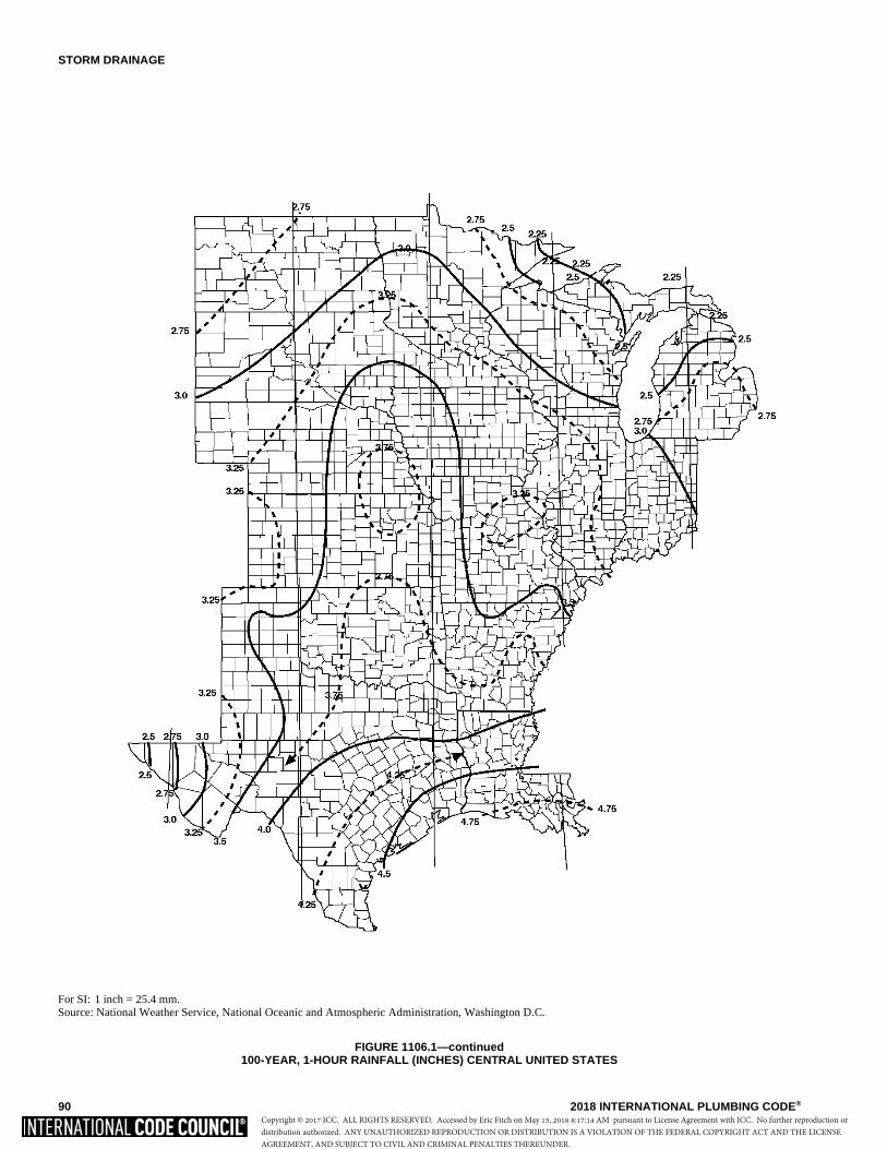
STORM DRAINAGE
90 2018 INTERNATIONAL PLUMBING CODE®
For SI: 1 inch = 25.4 mm.Source: National Weather Service, National Oceanic and Atmospheric Administration, Washington D.C.
FIGURE 1106.1—continued 100-YEAR, 1-HOUR RAINFALL (INCHES) CENTRAL UNITED STATES
Copyright © 2017 ICC. ALL RIGHTS RESERVED. Accessed by Eric Fitch on May 15, 2018 8:17:14 AM pursuant to License Agreement with ICC. No further reproduction ordistribution authorized. ANY UNAUTHORIZED REPRODUCTION OR DISTRIBUTION IS A VIOLATION OF THE FEDERAL COPYRIGHT ACT AND THE LICENSEAGREEMENT, AND SUBJECT TO CIVIL AND CRIMINAL PENALTIES THEREUNDER.

STORM DRAINAGE
2018 INTERNATIONAL PLUMBING CODE® 91
For SI: 1 inch = 25.4 mm.Source: National Weather Service, National Oceanic and Atmospheric Administration, Washington D.C.
FIGURE 1106.1—continued100-YEAR, 1-HOUR RAINFALL (INCHES) WESTERN UNITED STATES
Copyright © 2017 ICC. ALL RIGHTS RESERVED. Accessed by Eric Fitch on May 15, 2018 8:17:14 AM pursuant to License Agreement with ICC. No further reproduction ordistribution authorized. ANY UNAUTHORIZED REPRODUCTION OR DISTRIBUTION IS A VIOLATION OF THE FEDERAL COPYRIGHT ACT AND THE LICENSEAGREEMENT, AND SUBJECT TO CIVIL AND CRIMINAL PENALTIES THEREUNDER.

STORM DRAINAGE
92 2018 INTERNATIONAL PLUMBING CODE®
For SI: 1 inch = 25.4 mm.Source: National Weather Service, National Oceanic and Atmospheric Administration, Washington D.C.
FIGURE 1106.1—continued100-YEAR, 1-HOUR RAINFALL (INCHES) ALASKA
Copyright © 2017 ICC. ALL RIGHTS RESERVED. Accessed by Eric Fitch on May 15, 2018 8:17:14 AM pursuant to License Agreement with ICC. No further reproduction ordistribution authorized. ANY UNAUTHORIZED REPRODUCTION OR DISTRIBUTION IS A VIOLATION OF THE FEDERAL COPYRIGHT ACT AND THE LICENSEAGREEMENT, AND SUBJECT TO CIVIL AND CRIMINAL PENALTIES THEREUNDER.
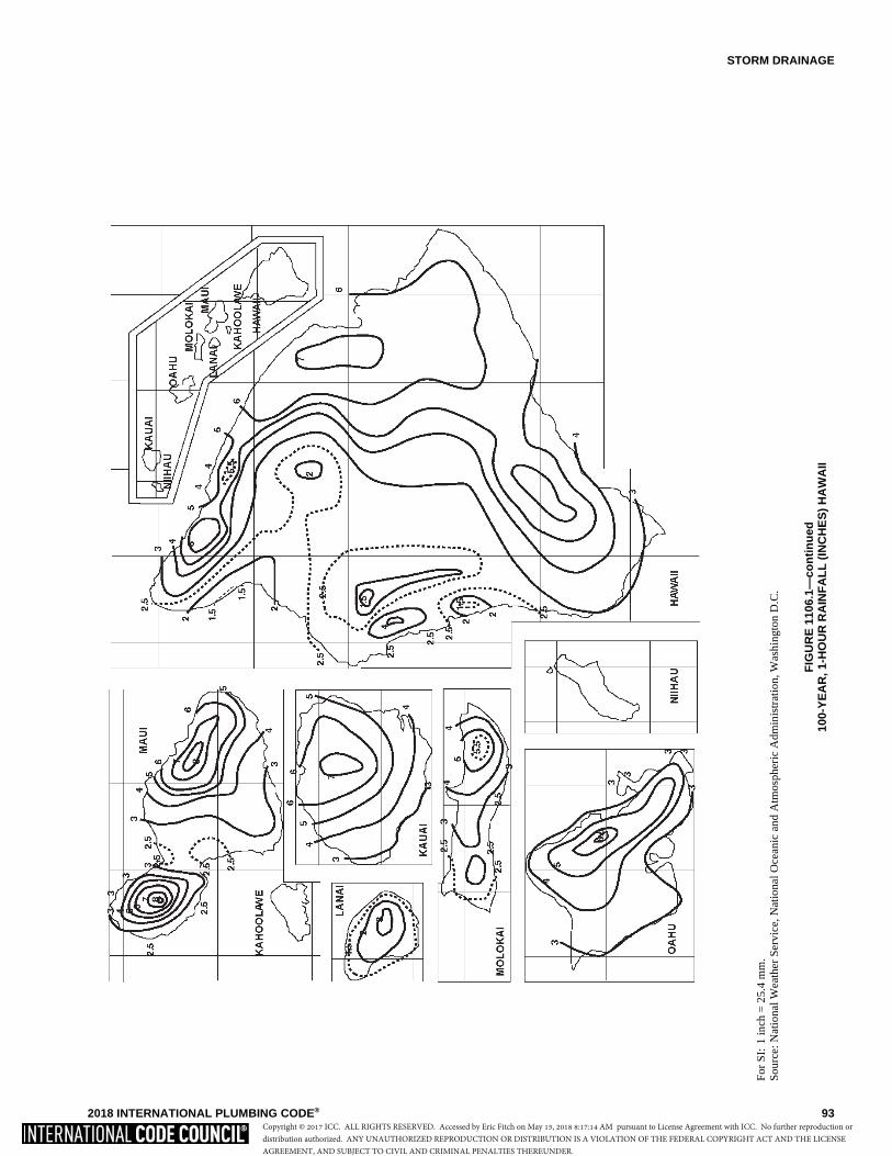
STORM DRAINAGE
2018 INTERNATIONAL PLUMBING CODE® 93
For
SI:
1 in
ch =
25.
4 m
m.
Sou
rce:
Nat
iona
l Wea
ther
Ser
vice
, Nat
iona
l Oce
anic
and
Atm
osph
eric
Adm
inis
trat
ion,
Was
hing
ton
D.C
.
FIG
UR
E 1
106.
1—co
nti
nu
ed10
0-Y
EA
R, 1
-HO
UR
RA
INF
AL
L (
INC
HE
S)
HA
WA
II
Copyright © 2017 ICC. ALL RIGHTS RESERVED. Accessed by Eric Fitch on May 15, 2018 8:17:14 AM pursuant to License Agreement with ICC. No further reproduction ordistribution authorized. ANY UNAUTHORIZED REPRODUCTION OR DISTRIBUTION IS A VIOLATION OF THE FEDERAL COPYRIGHT ACT AND THE LICENSEAGREEMENT, AND SUBJECT TO CIVIL AND CRIMINAL PENALTIES THEREUNDER.
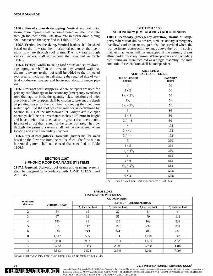
STORM DRAINAGE
94 2018 INTERNATIONAL PLUMBING CODE®
1106.2 Size of storm drain piping. Vertical and horizontalstorm drain piping shall be sized based on the flow ratethrough the roof drain. The flow rate in storm drain pipingshall not exceed that specified in Table 1106.2.
1106.3 Vertical leader sizing. Vertical leaders shall be sizedbased on the flow rate from horizontal gutters or the maxi-mum flow rate through roof drains. The flow rate throughvertical leaders shall not exceed that specified in Table1106.3.
1106.4 Vertical walls. In sizing roof drains and storm drain-age piping, one-half of the area of any vertical wall thatdiverts rainwater to the roof shall be added to the projectedroof area for inclusion in calculating the required size of ver-tical conductors, leaders and horizontal storm drainage pip-ing.
1106.5 Parapet wall scuppers. Where scuppers are used forprimary roof drainage or for secondary (emergency overflow)roof drainage or both, the quantity, size, location and inletelevation of the scuppers shall be chosen to prevent the depthof ponding water on the roof from exceeding the maximumwater depth that the roof was designed for as determined bySection 1611.1 of the International Building Code. Scupperopenings shall be not less than 4 inches (102 mm) in heightand have a width that is equal to or greater than the circum-ference of a roof drain sized for the same roof area. The flowthrough the primary system shall not be considered whenlocating and sizing secondary scuppers.
1106.6 Size of roof gutters. Horizontal gutters shall be sizedbased on the flow rate from the roof surface. The flow rate inhorizontal gutters shall not exceed that specified in Table1106.6.
SECTION 1107 SIPHONIC ROOF DRAINAGE SYSTEMS
1107.1 General. Siphonic roof drains and drainage systemsshall be designed in accordance with ASME A112.6.9 andASPE 45.
SECTION 1108 SECONDARY (EMERGENCY) ROOF DRAINS
1108.1 Secondary (emergency overflow) drains or scup-pers. Where roof drains are required, secondary (emergencyoverflow) roof drains or scuppers shall be provided where theroof perimeter construction extends above the roof in such amanner that water will be entrapped if the primary drainsallow buildup for any reason. Where primary and secondaryroof drains are manufactured as a single assembly, the inletand outlet for each drain shall be independent.
TABLE 1106.2STORM DRAIN PIPE SIZING
For SI: 1 inch = 25.4 mm, 1 foot = 304.8 mm, 1 gallon per minute = 3.785 L/m.
PIPE SIZE(inches)
CAPACITY (gpm)
VERTICAL DRAINSLOPE OF HORIZONTAL DRAIN
1/16 inch per foot 1/8 inch per foot 1/4 inch per foot 1/2 inch per foot
2 34 15 22 31 44
3 87 39 55 79 111
4 180 81 115 163 231
5 311 117 165 234 331
6 538 243 344 487 689
8 1,117 505 714 1,010 1,429
10 2,050 927 1,311 1,855 2,623
12 3,272 1,480 2,093 2,960 4,187
15 5,543 2,508 3,546 5,016 7,093
TABLE 1106.3VERTICAL LEADER SIZING
For SI: 1 inch = 25.4 mm, 1 gallon per minute = 3.785 L/m.
SIZE OF LEADER(inches)
CAPACITY(gpm)
2 30
2 × 2 30
11/2 × 21/2 30
21/2 54
21/2 × 21/2 54
3 92
2 × 4 92
21/2 × 3 92
4 192
3 × 41/4 192
31/2 × 4 192
5 360
4 × 5 360
41/2 × 41/2 360
6 563
5 × 6 563
51/2 × 51/2 563
8 1208
6 × 8 1208
Copyright © 2017 ICC. ALL RIGHTS RESERVED. Accessed by Eric Fitch on May 15, 2018 8:17:14 AM pursuant to License Agreement with ICC. No further reproduction ordistribution authorized. ANY UNAUTHORIZED REPRODUCTION OR DISTRIBUTION IS A VIOLATION OF THE FEDERAL COPYRIGHT ACT AND THE LICENSEAGREEMENT, AND SUBJECT TO CIVIL AND CRIMINAL PENALTIES THEREUNDER.
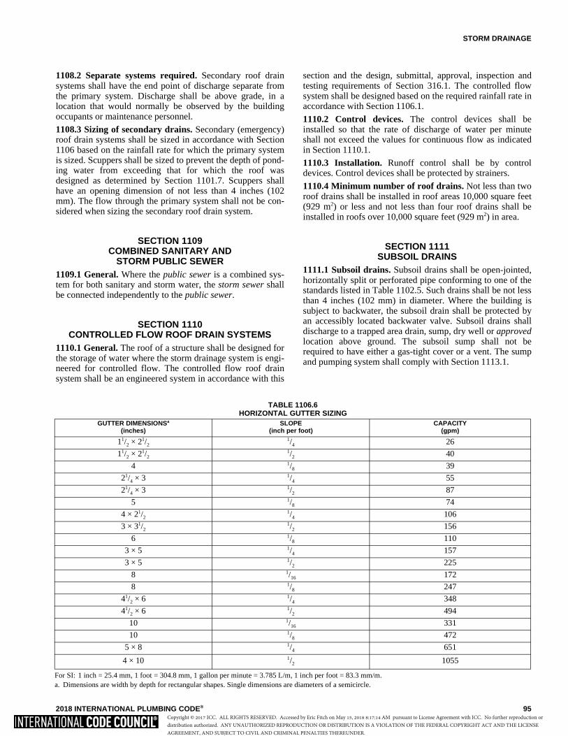
STORM DRAINAGE
2018 INTERNATIONAL PLUMBING CODE® 95
1108.2 Separate systems required. Secondary roof drainsystems shall have the end point of discharge separate fromthe primary system. Discharge shall be above grade, in alocation that would normally be observed by the buildingoccupants or maintenance personnel.
1108.3 Sizing of secondary drains. Secondary (emergency)roof drain systems shall be sized in accordance with Section1106 based on the rainfall rate for which the primary systemis sized. Scuppers shall be sized to prevent the depth of pond-ing water from exceeding that for which the roof wasdesigned as determined by Section 1101.7. Scuppers shallhave an opening dimension of not less than 4 inches (102mm). The flow through the primary system shall not be con-sidered when sizing the secondary roof drain system.
SECTION 1109 COMBINED SANITARY AND
STORM PUBLIC SEWER1109.1 General. Where the public sewer is a combined sys-tem for both sanitary and storm water, the storm sewer shallbe connected independently to the public sewer.
SECTION 1110 CONTROLLED FLOW ROOF DRAIN SYSTEMS
1110.1 General. The roof of a structure shall be designed forthe storage of water where the storm drainage system is engi-neered for controlled flow. The controlled flow roof drainsystem shall be an engineered system in accordance with this
section and the design, submittal, approval, inspection andtesting requirements of Section 316.1. The controlled flowsystem shall be designed based on the required rainfall rate inaccordance with Section 1106.1.
1110.2 Control devices. The control devices shall beinstalled so that the rate of discharge of water per minuteshall not exceed the values for continuous flow as indicatedin Section 1110.1.
1110.3 Installation. Runoff control shall be by controldevices. Control devices shall be protected by strainers.
1110.4 Minimum number of roof drains. Not less than tworoof drains shall be installed in roof areas 10,000 square feet(929 m2) or less and not less than four roof drains shall beinstalled in roofs over 10,000 square feet (929 m2) in area.
SECTION 1111 SUBSOIL DRAINS
1111.1 Subsoil drains. Subsoil drains shall be open-jointed,horizontally split or perforated pipe conforming to one of thestandards listed in Table 1102.5. Such drains shall be not lessthan 4 inches (102 mm) in diameter. Where the building issubject to backwater, the subsoil drain shall be protected byan accessibly located backwater valve. Subsoil drains shalldischarge to a trapped area drain, sump, dry well or approvedlocation above ground. The subsoil sump shall not berequired to have either a gas-tight cover or a vent. The sumpand pumping system shall comply with Section 1113.1.
TABLE 1106.6HORIZONTAL GUTTER SIZING
For SI: 1 inch = 25.4 mm, 1 foot = 304.8 mm, 1 gallon per minute = 3.785 L/m, 1 inch per foot = 83.3 mm/m.a. Dimensions are width by depth for rectangular shapes. Single dimensions are diameters of a semicircle.
GUTTER DIMENSIONSa
(inches)SLOPE
(inch per foot)CAPACITY
(gpm)
11/2 × 21/21/4 26
11/2 × 21/21/2 40
4 1/8 39
21/4 × 3 1/4 55
21/4 × 3 1/2 87
5 1/8 74
4 × 21/21/4 106
3 × 31/21/2 156
6 1/8 110
3 × 5 1/4 157
3 × 5 1/2 225
8 1/16 172
8 1/8 247
41/2 × 6 1/4 348
41/2 × 6 1/2 494
10 1/16 331
10 1/8 472
5 × 8 1/4 651
4 × 10 1/2 1055
Copyright © 2017 ICC. ALL RIGHTS RESERVED. Accessed by Eric Fitch on May 15, 2018 8:17:14 AM pursuant to License Agreement with ICC. No further reproduction ordistribution authorized. ANY UNAUTHORIZED REPRODUCTION OR DISTRIBUTION IS A VIOLATION OF THE FEDERAL COPYRIGHT ACT AND THE LICENSEAGREEMENT, AND SUBJECT TO CIVIL AND CRIMINAL PENALTIES THEREUNDER.
STORM DRAINAGE
96 2018 INTERNATIONAL PLUMBING CODE®
SECTION 1112 BUILDING SUBDRAINS
1112.1 Building subdrains. Building subdrains locatedbelow the public sewer level shall discharge into a sump orreceiving tank, the contents of which shall be automaticallylifted and discharged into the drainage system as required forbuilding sumps. The sump and pumping equipment shallcomply with Section 1113.1.
SECTION 1113 SUMPS AND PUMPING SYSTEMS
1113.1 Pumping system. The sump pump, pit and dischargepiping shall conform to Sections 1113.1.1 through 1113.1.4.
1113.1.1 Pump capacity and head. The sump pump shallbe of a capacity and head appropriate to anticipated userequirements.
1113.1.2 Sump pit. The sump pit shall be not less than 18inches (457 mm) in diameter and not less than 24 inches(610 mm) in depth, unless otherwise approved. The pitshall be provided with access and shall be located suchthat all drainage flows into the pit by gravity. The sump pitshall be constructed of tile, steel, plastic, cast iron, con-crete or other approved material, with a removable coveradequate to support anticipated loads in the area of use.The pit floor shall be solid and provide permanent supportfor the pump.
1113.1.3 Electrical. Electrical service outlets, whererequired, shall meet the requirements of NFPA 70.
1113.1.4 Piping. Discharge piping shall meet the require-ments of Section 1102.2, 1102.3 or 1102.4 and shallinclude a gate valve and a full flow check valve. Pipe andfittings shall be the same size as, or larger than, the pumpdischarge tapping.
Exception: In one- and two-family dwellings, only acheck valve shall be required, located on the dischargepiping from the pump or ejector.
Copyright © 2017 ICC. ALL RIGHTS RESERVED. Accessed by Eric Fitch on May 15, 2018 8:17:14 AM pursuant to License Agreement with ICC. No further reproduction ordistribution authorized. ANY UNAUTHORIZED REPRODUCTION OR DISTRIBUTION IS A VIOLATION OF THE FEDERAL COPYRIGHT ACT AND THE LICENSEAGREEMENT, AND SUBJECT TO CIVIL AND CRIMINAL PENALTIES THEREUNDER.
2018 INTERNATIONAL PLUMBING CODE® 97
CHAPTER 12
SPECIAL PIPING AND STORAGE SYSTEMS
User note:
About this chapter: Chapter 12 specifies the standards covering the installation of nonflammable medical gas piping systems and nonmedi-cal oxygen piping systems.
SECTION 1201GENERAL
1201.1 Scope. The provisions of this chapter shall govern thedesign and installation of piping and storage systems for non-flammable medical gas systems and nonmedical oxygen sys-tems. All maintenance and operations of such systems shallbe in accordance with the International Fire Code.
SECTION 1202MEDICAL GASES
[F] 1202.1 Nonflammable medical gases. Nonflammablemedical gas systems, inhalation anesthetic systems and vac-uum piping systems shall be designed and installed in accor-dance with NFPA 99.
Exceptions:1. This section shall not apply to portable systems or
cylinder storage.
2. Vacuum system exhaust terminations shall complywith the International Mechanical Code.
SECTION 1203OXYGEN SYSTEMS
[F] 1203.1 Design and installation. Nonmedical oxygen sys-tems shall be designed and installed in accordance withNFPA 55 and NFPA 51.
Copyright © 2017 ICC. ALL RIGHTS RESERVED. Accessed by Eric Fitch on May 15, 2018 8:17:14 AM pursuant to License Agreement with ICC. No further reproduction ordistribution authorized. ANY UNAUTHORIZED REPRODUCTION OR DISTRIBUTION IS A VIOLATION OF THE FEDERAL COPYRIGHT ACT AND THE LICENSEAGREEMENT, AND SUBJECT TO CIVIL AND CRIMINAL PENALTIES THEREUNDER.

98 2018 INTERNATIONAL PLUMBING CODE®
Copyright © 2017 ICC. ALL RIGHTS RESERVED. Accessed by Eric Fitch on May 15, 2018 8:17:14 AM pursuant to License Agreement with ICC. No further reproduction ordistribution authorized. ANY UNAUTHORIZED REPRODUCTION OR DISTRIBUTION IS A VIOLATION OF THE FEDERAL COPYRIGHT ACT AND THE LICENSEAGREEMENT, AND SUBJECT TO CIVIL AND CRIMINAL PENALTIES THEREUNDER.
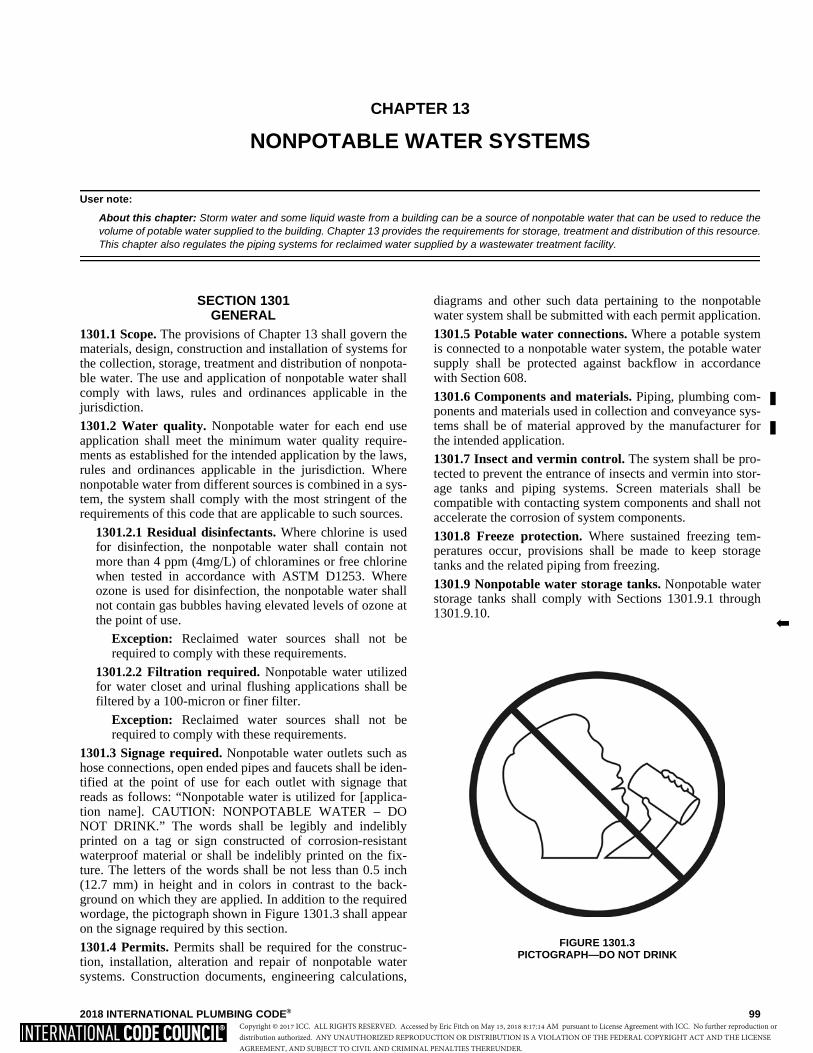
2018 INTERNATIONAL PLUMBING CODE® 99
CHAPTER 13
NONPOTABLE WATER SYSTEMS
User note:
About this chapter: Storm water and some liquid waste from a building can be a source of nonpotable water that can be used to reduce thevolume of potable water supplied to the building. Chapter 13 provides the requirements for storage, treatment and distribution of this resource.This chapter also regulates the piping systems for reclaimed water supplied by a wastewater treatment facility.
SECTION 1301GENERAL
1301.1 Scope. The provisions of Chapter 13 shall govern thematerials, design, construction and installation of systems forthe collection, storage, treatment and distribution of nonpota-ble water. The use and application of nonpotable water shallcomply with laws, rules and ordinances applicable in thejurisdiction.
1301.2 Water quality. Nonpotable water for each end useapplication shall meet the minimum water quality require-ments as established for the intended application by the laws,rules and ordinances applicable in the jurisdiction. Wherenonpotable water from different sources is combined in a sys-tem, the system shall comply with the most stringent of therequirements of this code that are applicable to such sources.
1301.2.1 Residual disinfectants. Where chlorine is usedfor disinfection, the nonpotable water shall contain notmore than 4 ppm (4mg/L) of chloramines or free chlorinewhen tested in accordance with ASTM D1253. Whereozone is used for disinfection, the nonpotable water shallnot contain gas bubbles having elevated levels of ozone atthe point of use.
Exception: Reclaimed water sources shall not berequired to comply with these requirements.
1301.2.2 Filtration required. Nonpotable water utilizedfor water closet and urinal flushing applications shall befiltered by a 100-micron or finer filter.
Exception: Reclaimed water sources shall not berequired to comply with these requirements.
1301.3 Signage required. Nonpotable water outlets such ashose connections, open ended pipes and faucets shall be iden-tified at the point of use for each outlet with signage thatreads as follows: “Nonpotable water is utilized for [applica-tion name]. CAUTION: NONPOTABLE WATER – DONOT DRINK.” The words shall be legibly and indeliblyprinted on a tag or sign constructed of corrosion-resistantwaterproof material or shall be indelibly printed on the fix-ture. The letters of the words shall be not less than 0.5 inch(12.7 mm) in height and in colors in contrast to the back-ground on which they are applied. In addition to the requiredwordage, the pictograph shown in Figure 1301.3 shall appearon the signage required by this section.
1301.4 Permits. Permits shall be required for the construc-tion, installation, alteration and repair of nonpotable watersystems. Construction documents, engineering calculations,
diagrams and other such data pertaining to the nonpotablewater system shall be submitted with each permit application.
1301.5 Potable water connections. Where a potable systemis connected to a nonpotable water system, the potable watersupply shall be protected against backflow in accordancewith Section 608.
1301.6 Components and materials. Piping, plumbing com-ponents and materials used in collection and conveyance sys-tems shall be of material approved by the manufacturer forthe intended application.
1301.7 Insect and vermin control. The system shall be pro-tected to prevent the entrance of insects and vermin into stor-age tanks and piping systems. Screen materials shall becompatible with contacting system components and shall notaccelerate the corrosion of system components.
1301.8 Freeze protection. Where sustained freezing tem-peratures occur, provisions shall be made to keep storagetanks and the related piping from freezing.
1301.9 Nonpotable water storage tanks. Nonpotable waterstorage tanks shall comply with Sections 1301.9.1 through1301.9.10. �
FIGURE 1301.3PICTOGRAPH—DO NOT DRINK
Copyright © 2017 ICC. ALL RIGHTS RESERVED. Accessed by Eric Fitch on May 15, 2018 8:17:14 AM pursuant to License Agreement with ICC. No further reproduction ordistribution authorized. ANY UNAUTHORIZED REPRODUCTION OR DISTRIBUTION IS A VIOLATION OF THE FEDERAL COPYRIGHT ACT AND THE LICENSEAGREEMENT, AND SUBJECT TO CIVIL AND CRIMINAL PENALTIES THEREUNDER.
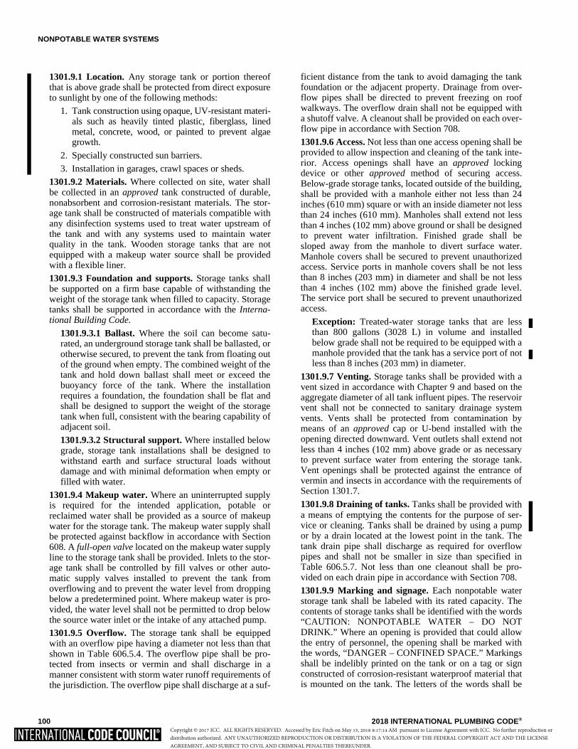
NONPOTABLE WATER SYSTEMS
100 2018 INTERNATIONAL PLUMBING CODE®
1301.9.1 Location. Any storage tank or portion thereofthat is above grade shall be protected from direct exposureto sunlight by one of the following methods:
1. Tank construction using opaque, UV-resistant materi-als such as heavily tinted plastic, fiberglass, linedmetal, concrete, wood, or painted to prevent algaegrowth.
2. Specially constructed sun barriers.
3. Installation in garages, crawl spaces or sheds.
1301.9.2 Materials. Where collected on site, water shallbe collected in an approved tank constructed of durable,nonabsorbent and corrosion-resistant materials. The stor-age tank shall be constructed of materials compatible withany disinfection systems used to treat water upstream ofthe tank and with any systems used to maintain waterquality in the tank. Wooden storage tanks that are notequipped with a makeup water source shall be providedwith a flexible liner.
1301.9.3 Foundation and supports. Storage tanks shallbe supported on a firm base capable of withstanding theweight of the storage tank when filled to capacity. Storagetanks shall be supported in accordance with the Interna-tional Building Code.
1301.9.3.1 Ballast. Where the soil can become satu-rated, an underground storage tank shall be ballasted, orotherwise secured, to prevent the tank from floating outof the ground when empty. The combined weight of thetank and hold down ballast shall meet or exceed thebuoyancy force of the tank. Where the installationrequires a foundation, the foundation shall be flat andshall be designed to support the weight of the storagetank when full, consistent with the bearing capability ofadjacent soil.
1301.9.3.2 Structural support. Where installed belowgrade, storage tank installations shall be designed towithstand earth and surface structural loads withoutdamage and with minimal deformation when empty orfilled with water.
1301.9.4 Makeup water. Where an uninterrupted supplyis required for the intended application, potable orreclaimed water shall be provided as a source of makeupwater for the storage tank. The makeup water supply shallbe protected against backflow in accordance with Section608. A full-open valve located on the makeup water supplyline to the storage tank shall be provided. Inlets to the stor-age tank shall be controlled by fill valves or other auto-matic supply valves installed to prevent the tank fromoverflowing and to prevent the water level from droppingbelow a predetermined point. Where makeup water is pro-vided, the water level shall not be permitted to drop belowthe source water inlet or the intake of any attached pump.
1301.9.5 Overflow. The storage tank shall be equippedwith an overflow pipe having a diameter not less than thatshown in Table 606.5.4. The overflow pipe shall be pro-tected from insects or vermin and shall discharge in amanner consistent with storm water runoff requirements ofthe jurisdiction. The overflow pipe shall discharge at a suf-
ficient distance from the tank to avoid damaging the tankfoundation or the adjacent property. Drainage from over-flow pipes shall be directed to prevent freezing on roofwalkways. The overflow drain shall not be equipped witha shutoff valve. A cleanout shall be provided on each over-flow pipe in accordance with Section 708.
1301.9.6 Access. Not less than one access opening shall beprovided to allow inspection and cleaning of the tank inte-rior. Access openings shall have an approved lockingdevice or other approved method of securing access.Below-grade storage tanks, located outside of the building,shall be provided with a manhole either not less than 24inches (610 mm) square or with an inside diameter not lessthan 24 inches (610 mm). Manholes shall extend not lessthan 4 inches (102 mm) above ground or shall be designedto prevent water infiltration. Finished grade shall besloped away from the manhole to divert surface water.Manhole covers shall be secured to prevent unauthorizedaccess. Service ports in manhole covers shall be not lessthan 8 inches (203 mm) in diameter and shall be not lessthan 4 inches (102 mm) above the finished grade level.The service port shall be secured to prevent unauthorizedaccess.
Exception: Treated-water storage tanks that are lessthan 800 gallons (3028 L) in volume and installedbelow grade shall not be required to be equipped with amanhole provided that the tank has a service port of notless than 8 inches (203 mm) in diameter.
1301.9.7 Venting. Storage tanks shall be provided with avent sized in accordance with Chapter 9 and based on theaggregate diameter of all tank influent pipes. The reservoirvent shall not be connected to sanitary drainage systemvents. Vents shall be protected from contamination bymeans of an approved cap or U-bend installed with theopening directed downward. Vent outlets shall extend notless than 4 inches (102 mm) above grade or as necessaryto prevent surface water from entering the storage tank.Vent openings shall be protected against the entrance ofvermin and insects in accordance with the requirements ofSection 1301.7.
1301.9.8 Draining of tanks. Tanks shall be provided witha means of emptying the contents for the purpose of ser-vice or cleaning. Tanks shall be drained by using a pumpor by a drain located at the lowest point in the tank. Thetank drain pipe shall discharge as required for overflowpipes and shall not be smaller in size than specified inTable 606.5.7. Not less than one cleanout shall be pro-vided on each drain pipe in accordance with Section 708.
1301.9.9 Marking and signage. Each nonpotable waterstorage tank shall be labeled with its rated capacity. Thecontents of storage tanks shall be identified with the words“CAUTION: NONPOTABLE WATER – DO NOTDRINK.” Where an opening is provided that could allowthe entry of personnel, the opening shall be marked withthe words, “DANGER – CONFINED SPACE.” Markingsshall be indelibly printed on the tank or on a tag or signconstructed of corrosion-resistant waterproof material thatis mounted on the tank. The letters of the words shall be
Copyright © 2017 ICC. ALL RIGHTS RESERVED. Accessed by Eric Fitch on May 15, 2018 8:17:14 AM pursuant to License Agreement with ICC. No further reproduction ordistribution authorized. ANY UNAUTHORIZED REPRODUCTION OR DISTRIBUTION IS A VIOLATION OF THE FEDERAL COPYRIGHT ACT AND THE LICENSEAGREEMENT, AND SUBJECT TO CIVIL AND CRIMINAL PENALTIES THEREUNDER.

NONPOTABLE WATER SYSTEMS
2018 INTERNATIONAL PLUMBING CODE® 101
not less than 0.5 inch (12.7 mm) in height and shall be of acolor in contrast with the background on which they areapplied.
1301.9.10 Storage tank tests. Storage tanks shall betested in accordance with the following:
Storage tanks shall be filled with water to the overflowline prior to and during inspection. Seams and jointsshall be left exposed and the tank shall remain watertight without leakage for a period of 24 hours.
1. After 24 hours, supplemental water shall be intro-duced for a period of 15 minutes to verify properdrainage of the overflow system and that thereare no leaks.
2. The tank drain shall be observed for proper oper-ation.
3. The makeup water system shall be observed forproper operation and successful automatic shut-off of the system at the refill threshold shall beverified.
1301.10 System abandonment. If the owner of an on-sitenonpotable water reuse system or rainwater collection andconveyance system elects to cease use of, or fails to properlymaintain such system, the system shall be abandoned andshall comply with the following:
1. All system piping connecting to a utility-providedwater system shall be removed or disabled.
2. The distribution piping system shall be replaced withan approved potable water supply piping system.Where an existing potable pipe system is already inplace, the fixtures shall be connected to the existingsystem.
3. The storage tank shall be secured from accidentalaccess by sealing or locking tank inlets and accesspoints, or filling with sand or equivalent.
1301.11 Trenching requirements for nonpotable waterpiping. Nonpotable water collection and distribution pipingand reclaimed water piping shall be separated from the build-ing sewer and potable water piping underground by 5 feet(1524 mm) of undisturbed or compacted earth. Nonpotablewater collection and distribution piping shall not be locatedin, under or above cesspools, septic tanks, septic tank drain-age fields or seepage pits. Buried nonpotable water pipingshall comply with the requirements of Section 306.
Exceptions:1. The required separation distance shall not apply
where the bottom of the nonpotable water pipewithin 5 feet (1524 mm) of the sewer is not less than12 inches (305 mm) above the top of the highestpoint of the sewer and the pipe materials conform toTable 702.3.
2. The required separation distance shall not applywhere the bottom of the potable water service pipewithin 5 feet (1524 mm) of the nonpotable waterpipe is not less than 12 inches (305 mm) above thetop of the highest point of the nonpotable water pipeand the pipe materials comply with the requirementsof Table 605.4.
3. Nonpotable water pipe is permitted to be located inthe same trench with a building sewer, provided thatsuch sewer is constructed of materials that complywith the requirements of Table 702.2.
4. The required separation distance shall not applywhere a nonpotable water pipe crosses a sewer pipe,provided that the pipe is sleeved to not less than 5feet (1524 mm) horizontally from the sewer pipecenterline on both sides of such crossing, with pipematerials that comply with Table 702.2.
5. The required separation distance shall not applywhere a potable water service pipe crosses a nonpo-table water pipe, provided that the potable water ser-vice pipe is sleeved for a distance of not less than 5feet (1524 mm) horizontally from the centerline ofthe nonpotable pipe on both sides of such crossing,with pipe materials that comply with Table 702.2.
6. Irrigation piping located outside of a building anddownstream of the backflow preventer is notrequired to meet the trenching requirements wherenonpotable water is used for outdoor applications.
1301.12 Outdoor outlet access. Sillcocks, hose bibbs, wallhydrants, yard hydrants and other outdoor outlets supplied bynonpotable water shall be located in a locked vault or shall beoperable only by means of a removable key.
SECTION 1302ON-SITE NONPOTABLE WATER REUSE SYSTEMS
1302.1 General. The provisions of ASTM E2635 and Sec-tion 1302 shall govern the construction, installation, alter-ation and repair of on-site nonpotable water reuse systems forthe collection, storage, treatment and distribution of on-sitesources of nonpotable water as permitted by the jurisdiction.
1302.2 Sources. On-site nonpotable water reuse systemsshall collect waste discharge from only the following sources:bathtubs, showers, lavatories, clothes washers and laundrytrays. Where approved and as appropriate for the intendedapplication, water from other nonpotable sources shall be col-lected for reuse by on-site nonpotable water reuse systems,
1302.2.1 Prohibited sources. Waste water containingurine or fecal matter shall not be diverted to on-site nonpo-table water reuse systems and shall discharge to the sani-tary drainage system of the building or premises inaccordance with Chapter 7. Reverse osmosis system rejectwater, water softener discharge water, kitchen sink wastewater, dishwasher waste water and waste water dischargedfrom wet-hood scrubbers shall not be collected for reuse inan on-site nonpotable water reuse system.
1302.3 Traps. Traps serving fixtures and devices dischargingwaste water to on-site nonpotable water reuse systems shallcomply with Section 1002.4.
1302.4 Collection pipe. On-site nonpotable water reuse sys-tems shall utilize drainage piping approved for use in plumb-ing drainage systems to collect and convey untreated waterfor reuse. Vent piping approved for use in plumbing ventingsystems shall be utilized for vents in the gray water system.
Copyright © 2017 ICC. ALL RIGHTS RESERVED. Accessed by Eric Fitch on May 15, 2018 8:17:14 AM pursuant to License Agreement with ICC. No further reproduction ordistribution authorized. ANY UNAUTHORIZED REPRODUCTION OR DISTRIBUTION IS A VIOLATION OF THE FEDERAL COPYRIGHT ACT AND THE LICENSEAGREEMENT, AND SUBJECT TO CIVIL AND CRIMINAL PENALTIES THEREUNDER.
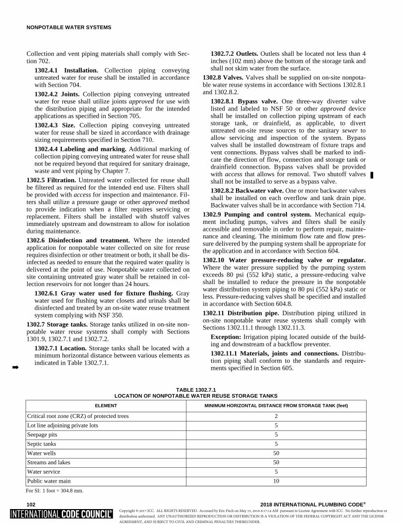
NONPOTABLE WATER SYSTEMS
102 2018 INTERNATIONAL PLUMBING CODE®
Collection and vent piping materials shall comply with Sec-tion 702.
1302.4.1 Installation. Collection piping conveyinguntreated water for reuse shall be installed in accordancewith Section 704.
1302.4.2 Joints. Collection piping conveying untreatedwater for reuse shall utilize joints approved for use withthe distribution piping and appropriate for the intendedapplications as specified in Section 705.
1302.4.3 Size. Collection piping conveying untreatedwater for reuse shall be sized in accordance with drainagesizing requirements specified in Section 710.
1302.4.4 Labeling and marking. Additional marking ofcollection piping conveying untreated water for reuse shallnot be required beyond that required for sanitary drainage,waste and vent piping by Chapter 7.
1302.5 Filtration. Untreated water collected for reuse shallbe filtered as required for the intended end use. Filters shallbe provided with access for inspection and maintenance. Fil-ters shall utilize a pressure gauge or other approved methodto provide indication when a filter requires servicing orreplacement. Filters shall be installed with shutoff valvesimmediately upstream and downstream to allow for isolationduring maintenance.
1302.6 Disinfection and treatment. Where the intendedapplication for nonpotable water collected on site for reuserequires disinfection or other treatment or both, it shall be dis-infected as needed to ensure that the required water quality isdelivered at the point of use. Nonpotable water collected onsite containing untreated gray water shall be retained in col-lection reservoirs for not longer than 24 hours.
1302.6.1 Gray water used for fixture flushing. Graywater used for flushing water closets and urinals shall bedisinfected and treated by an on-site water reuse treatmentsystem complying with NSF 350.
1302.7 Storage tanks. Storage tanks utilized in on-site non-potable water reuse systems shall comply with Sections1301.9, 1302.7.1 and 1302.7.2.
1302.7.1 Location. Storage tanks shall be located with aminimum horizontal distance between various elements asindicated in Table 1302.7.1.
1302.7.2 Outlets. Outlets shall be located not less than 4inches (102 mm) above the bottom of the storage tank andshall not skim water from the surface.
1302.8 Valves. Valves shall be supplied on on-site nonpota-ble water reuse systems in accordance with Sections 1302.8.1and 1302.8.2.
1302.8.1 Bypass valve. One three-way diverter valvelisted and labeled to NSF 50 or other approved deviceshall be installed on collection piping upstream of eachstorage tank, or drainfield, as applicable, to divertuntreated on-site reuse sources to the sanitary sewer toallow servicing and inspection of the system. Bypassvalves shall be installed downstream of fixture traps andvent connections. Bypass valves shall be marked to indi-cate the direction of flow, connection and storage tank ordrainfield connection. Bypass valves shall be providedwith access that allows for removal. Two shutoff valvesshall not be installed to serve as a bypass valve.
1302.8.2 Backwater valve. One or more backwater valvesshall be installed on each overflow and tank drain pipe.Backwater valves shall be in accordance with Section 714.
1302.9 Pumping and control system. Mechanical equip-ment including pumps, valves and filters shall be easilyaccessible and removable in order to perform repair, mainte-nance and cleaning. The minimum flow rate and flow pres-sure delivered by the pumping system shall be appropriate forthe application and in accordance with Section 604.
1302.10 Water pressure-reducing valve or regulator.Where the water pressure supplied by the pumping systemexceeds 80 psi (552 kPa) static, a pressure-reducing valveshall be installed to reduce the pressure in the nonpotablewater distribution system piping to 80 psi (552 kPa) static orless. Pressure-reducing valves shall be specified and installedin accordance with Section 604.8.
1302.11 Distribution pipe. Distribution piping utilized inon-site nonpotable water reuse systems shall comply withSections 1302.11.1 through 1302.11.3.
Exception: Irrigation piping located outside of the build-ing and downstream of a backflow preventer.
1302.11.1 Materials, joints and connections. Distribu-tion piping shall conform to the standards and require-ments specified in Section 605.�
TABLE 1302.7.1LOCATION OF NONPOTABLE WATER REUSE STORAGE TANKS
For SI: 1 foot = 304.8 mm.
ELEMENT MINIMUM HORIZONTAL DISTANCE FROM STORAGE TANK (feet)
Critical root zone (CRZ) of protected trees 2
Lot line adjoining private lots 5
Seepage pits 5
Septic tanks 5
Water wells 50
Streams and lakes 50
Water service 5
Public water main 10
Copyright © 2017 ICC. ALL RIGHTS RESERVED. Accessed by Eric Fitch on May 15, 2018 8:17:14 AM pursuant to License Agreement with ICC. No further reproduction ordistribution authorized. ANY UNAUTHORIZED REPRODUCTION OR DISTRIBUTION IS A VIOLATION OF THE FEDERAL COPYRIGHT ACT AND THE LICENSEAGREEMENT, AND SUBJECT TO CIVIL AND CRIMINAL PENALTIES THEREUNDER.

NONPOTABLE WATER SYSTEMS
2018 INTERNATIONAL PLUMBING CODE® 103
1302.11.2 Design. On-site nonpotable water reuse distri-bution piping systems shall be designed and sized in ac-cordance with Section 604 for the intended application.
1302.11.3 Marking. On-site nonpotable water distributionpiping labeling and marking shall comply with Section608.9.
1302.12 Tests and inspections. Tests and inspections shallbe performed in accordance with Sections 1302.12.1 through1302.12.6.
1302.12.1 Collection pipe and vent test. Drain, waste andvent piping used for on-site water reuse systems shall betested in accordance with Section 312.
1302.12.2 Storage tank test. Storage tanks shall be testedin accordance with Section 1301.9.10.
1302.12.3 Water supply system test. The testing ofmakeup water supply piping and distribution piping shallbe conducted in accordance with Section 312.5.
1302.12.4 Inspection and testing of backflow preven-tion assemblies. The testing of backflow preventers andbackwater valves shall be conducted in accordance withSection 312.10.
1302.12.5 Inspection of vermin and insect protection.Inlets and vents to the system shall be inspected to verifythat each is protected to prevent the entrance of insects andvermin into the storage tank and piping systems in accor-dance with Section 1301.7.
1302.12.6 Water quality test. The quality of the water forthe intended application shall be verified at the point ofuse in accordance with the requirements of the jurisdic-tion.
1302.13 Operation and maintenance manuals. Operationand maintenance materials shall be supplied with nonpotableon-site water reuse systems in accordance with Sections1302.13.1 through 1302.13.4.
1302.13.1 Manual. A detailed operations and mainte-nance manual shall be supplied in hardcopy form with allsystems.
1302.13.2 Schematics. The manual shall include adetailed system schematic, and the locations and a list ofall system components, including manufacturer and modelnumber.
1302.13.3 Maintenance procedures. The manual shallprovide a schedule and procedures for all system compo-nents requiring periodic maintenance. Consumable parts,including filters, shall be noted along with part numbers.
1302.13.4 Operations procedures. The manual shallinclude system startup and shutdown procedures. Themanual shall include detailed operating procedures for thesystem.
SECTION 1303NONPOTABLE RAINWATER COLLECTION
AND DISTRIBUTION SYSTEMS1303.1 General. The provisions of Section 1303 shall governthe construction, installation, alteration and repair of rainwa-
ter collection and conveyance systems for the collection, stor-age, treatment and distribution of rainwater for nonpotableapplications, as permitted by the jurisdiction.
1303.1.1 Fire protection systems. The storage, treatmentand distribution of nonpotable water to be used for fireprotection systems shall be in accordance with the Interna-tional Fire Code.
1303.2 Collection surface. Rainwater shall be collected onlyfrom above-ground impervious roofing surfaces constructedfrom approved materials and where approved, vehicularparking or pedestrian walking surfaces.
1303.3 Debris excluders. Downspouts and leaders shall beconnected to a debris excluder or equivalent device that isdesigned to remove leaves, sticks, pine needles and similardebris to prevent such from entering the storage tank.
1303.4 First-flush diverter. First-flush diverters shall oper-ate automatically and shall not rely on manually operatedvalves or devices. Diverted rainwater shall not be drained tothe roof surface, and shall be discharged in a manner consis-tent with the storm water runoff requirements of the jurisdic-tion. First-flush diverters shall be provided with access formaintenance and service.
1303.5 Roof gutters and downspouts. Gutters and down-spouts shall be constructed of materials that are compatiblewith the collection surface and the rainwater quality for thedesired end use. Joints shall be water tight.
1303.5.1 Slope. Roof gutters, leaders and rainwater collec-tion piping shall slope continuously toward collectioninlets. Gutters and downspouts shall have a slope of notless than 1/8 inch per foot (10.4 mm/m) along their entirelength, and shall not permit the collection or pooling ofwater at any point.
Exception: Siphonic drainage systems installed inaccordance with the manufacturer’s instructions shallnot be required to have a slope.
1303.5.2 Size. Gutters and downspouts shall be installedand sized in accordance with Section 1106.6 and localrainfall rates.
1303.5.3 Cleanouts. Cleanouts shall be provided in thewater conveyance system to allow access to all filters,flushes, pipes and downspouts.
1303.6 Drainage. Water drained from the roof washer ordebris excluder shall not be drained to the sanitary sewer.Such water shall be diverted from the storage tank and dis-charge in a location that will not cause erosion or damage toproperty in accordance with the International Building Code.Roof washers and debris excluders shall be provided with anautomatic means of self-draining between rain events, andshall not drain onto roof surfaces.
1303.7 Collection pipe. Rainwater collection and convey-ance systems shall utilize drainage piping approved for usewithin plumbing drainage systems to collect and convey cap-tured rainwater. Vent piping approved for use within plumb-ing venting systems shall be utilized for vents within therainwater system. Collection and vent piping materials shallcomply with Section 702.
Copyright © 2017 ICC. ALL RIGHTS RESERVED. Accessed by Eric Fitch on May 15, 2018 8:17:14 AM pursuant to License Agreement with ICC. No further reproduction ordistribution authorized. ANY UNAUTHORIZED REPRODUCTION OR DISTRIBUTION IS A VIOLATION OF THE FEDERAL COPYRIGHT ACT AND THE LICENSEAGREEMENT, AND SUBJECT TO CIVIL AND CRIMINAL PENALTIES THEREUNDER.

NONPOTABLE WATER SYSTEMS
104 2018 INTERNATIONAL PLUMBING CODE®
1303.7.1 Installation. Collection piping conveying cap-tured rainwater shall be installed in accordance with Sec-tion 704.
1303.7.2 Joints. Collection piping conveying capturedrainwater shall utilize joints approved for use with the dis-tribution piping and appropriate for the intended applica-tions as specified in Section 705.
1303.7.3 Size. Collection piping conveying captured rain-water shall be sized in accordance with drainage sizingrequirements specified in Section 710.
1303.7.4 Marking. Additional marking of collection pip-ing conveying captured rainwater for reuse shall not berequired beyond that required for sanitary drainage, wasteand vent piping by Chapter 7.
1303.8 Filtration. Collected rainwater shall be filtered asrequired for the intended end use. Filters shall be providedwith access for inspection and maintenance. Filters shall uti-lize a pressure gauge or other approved method to provideindication when a filter requires servicing or replacement.Filters shall be installed with shutoff valves installed immedi-ately upstream and downstream to allow for isolation duringmaintenance.
1303.9 Disinfection. Where the intended application for rain-water requires disinfection or other treatment or both, it shallbe disinfected as needed to ensure that the required waterquality is delivered at the point of use. Where chlorine is usedfor disinfection or treatment, water shall be tested for residualchlorine in accordance with ASTM D1253. The levels ofresidual chlorine shall not exceed that allowed for theintended use in accordance with the requirements of the juris-diction.
1303.10 Storage tanks. Storage tanks utilized in nonpotablerainwater collection and conveyance systems shall complywith Sections 1301.9 and 1303.10.1 through 1303.10.3.
1303.10.1 Location. Storage tanks shall be located with aminimum horizontal distance between various elements asindicated in Table 1303.10.1.
1303.10.2 Inlets. Storage tank inlets shall be designed tointroduce collected rainwater into the tank with minimumturbulence, and shall be located and designed to avoid agi-tating the contents of the storage tank.
1303.10.3 Outlets. Outlets shall be located not less than 4inches (102 mm) above the bottom of the storage tank andshall not skim water from the surface.
1303.11 Valves. Valves shall be supplied on rainwater col-lection and conveyance systems in accordance with Section1303.11.1.
1303.11.1 Backwater valve. Backwater valves shall beinstalled on each overflow and tank drain pipe. Backwatervalves shall be in accordance with Section 714.
1303.12 Pumping and control system. Mechanical equip-ment including pumps, valves and filters shall be providedwith access that allows for removal in order to performrepair, maintenance and cleaning. The minimum flow rateand flow pressure delivered by the pumping system shall beappropriate for the application and in accordance with Sec-tion 604.
1303.13 Water pressure-reducing valve or regulator.Where the water pressure supplied by the pumping systemexceeds 80 psi (552 kPa) static, a pressure-reducing valveshall be installed to reduce the pressure in the rainwater dis-tribution system piping to 80 psi (552 kPa) static or less.Pressure-reducing valves shall be specified and installed inaccordance with Section 604.8.
1303.14 Distribution pipe. Distribution piping utilized inrainwater collection and conveyance systems shall complywith Sections 1303.14.1 through 1303.14.3.
Exception: Irrigation piping located outside of the build-ing and downstream of a backflow preventer.
1303.14.1 Materials, joints and connections. Distribu-tion piping shall conform to the standards and require-ments specified in Section 605 for nonpotable water.
1303.14.2 Design. Distribution piping systems shall bedesigned and sized in accordance with Section 604 for theintended application.
1303.14.3 Marking. Nonpotable rainwater distributionpiping labeling and marking shall comply with Section608.9.
1303.15 Tests and inspections. Tests and inspections shallbe performed in accordance with Sections 1303.15.1 through1303.15.9.
1303.15.1 Roof gutter inspection and test. Roof guttersshall be inspected to verify that the installation and slopeis in accordance with Section 1303.5.1. Gutters shall betested by pouring not less than 1 gallon (3.8 l) of waterinto the end of the gutter opposite the collection point. Thegutter being tested shall not leak and shall not retain stand-ing water.
1303.15.2 First-flush diverter test. First-flush divertersshall be tested by introducing water into the collection sys-tem upstream of the diverter. Proper diversion of the firstamount of water shall be in accordance with the require-ments of Section 1303.4.
TABLE 1303.10.1LOCATION OF RAINWATER STORAGE TANKS
For SI: 1 foot = 304.8 mm.
ELEMENT MINIMUM HORIZONTAL DISTANCE FROM STORAGE TANK (feet)
Critical root zone (CRZ) of protected trees 2
Lot line adjoining private lots 5
Seepage pits 5
Septic tanks 5
Copyright © 2017 ICC. ALL RIGHTS RESERVED. Accessed by Eric Fitch on May 15, 2018 8:17:14 AM pursuant to License Agreement with ICC. No further reproduction ordistribution authorized. ANY UNAUTHORIZED REPRODUCTION OR DISTRIBUTION IS A VIOLATION OF THE FEDERAL COPYRIGHT ACT AND THE LICENSEAGREEMENT, AND SUBJECT TO CIVIL AND CRIMINAL PENALTIES THEREUNDER.
NONPOTABLE WATER SYSTEMS
2018 INTERNATIONAL PLUMBING CODE® 105
1303.15.3 Collection pipe and vent test. Drain, waste andvent piping used for rainwater collection and conveyancesystems shall be tested in accordance with Section 312.
1303.15.4 Storage tank test. Storage tanks shall be testedin accordance with Section 1301.9.10.
1303.15.5 Water supply system test. The testing ofmakeup water supply piping and distribution piping shallbe conducted in accordance with Section 312.5.
1303.15.6 Inspection and testing of backflow preven-tion assemblies. The testing of backflow preventers andbackwater valves shall be conducted in accordance withSection 312.10.
1303.15.7 Inspection of vermin and insect protection.Inlets and vents to the system shall be inspected to verifythat each is protected to prevent the entrance of insects andvermin into the storage tank and piping systems in accor-dance with Section 1301.7.
1303.15.8 Water quality test. The quality of the water forthe intended application shall be verified at the point ofuse in accordance with the requirements of the jurisdic-tion.
1303.15.9 Collected raw rainwater quality. ASTME2727 shall be used to determine what, if any, site condi-tions impact the quality of collected raw rainwater andwhether those site conditions require treatment of the rawwater for the intended end use or make the water unsuit-able for specific end uses.
1303.16 Operation and maintenance manuals. Operationand maintenance manuals shall be supplied with rainwatercollection and conveyance systems in accordance with Sec-tions 1303.16.1 through 1303.16.4.
1303.16.1 Manual. A detailed operations and mainte-nance manual shall be supplied in hardcopy form with allsystems.
1303.16.2 Schematics. The manual shall include adetailed system schematic, and locations and a list of allsystem components, including manufacturer and modelnumber.
1303.16.3 Maintenance procedures. The manual shallprovide a maintenance schedule and procedures for allsystem components requiring periodic maintenance. Con-sumable parts, including filters, shall be noted along withpart numbers.
1303.16.4 Operations procedures. The manual shallinclude system startup and shutdown procedures, as wellas detailed operating procedures.
SECTION 1304RECLAIMED WATER SYSTEMS
1304.1 General. The provisions of this section shall governthe construction, installation, alteration and repair of systemssupplying nonpotable reclaimed water.
1304.2 Water pressure-reducing valve or regulator.Where the reclaimed water pressure supplied to the buildingexceeds 80 psi (552 kPa) static, a pressure-reducing valveshall be installed to reduce the pressure in the reclaimedwater distribution system piping to 80 psi (552 kPa) static orless. Pressure-reducing valves shall be specified and installedin accordance with Section 604.8.
1304.3 Reclaimed water systems. The design of thereclaimed water systems shall conform to accepted engineer-ing practice.
1304.3.1 Distribution pipe. Distribution piping shallcomply with Sections 1304.3.1.1 through 1304.3.1.3.
Exception: Irrigation piping located outside of thebuilding and downstream of a backflow preventer.
1304.3.1.1 Materials, joints and connections. Distri-bution piping conveying reclaimed water shall conformto standards and requirements specified in Section 605for nonpotable water.
1304.3.1.2 Design. Distribution piping systems shall bedesigned and sized in accordance with Section 604 forthe intended application.
1304.3.1.3 Labeling and marking. Nonpotable distri-bution piping labeling and marking shall comply withSection 608.9.
1304.4 Tests and inspections. Tests and inspections shall beperformed in accordance with Sections 1304.4.1 and1304.4.2.
1304.4.1 Water supply system test. The testing ofmakeup water supply piping and reclaimed water distribu-tion piping shall be conducted in accordance with Section312.5.
1304.4.2 Inspection and testing of backflow preventionassemblies. The testing of backflow preventers shall beconducted in accordance with Section 312.10.
�
Copyright © 2017 ICC. ALL RIGHTS RESERVED. Accessed by Eric Fitch on May 15, 2018 8:17:14 AM pursuant to License Agreement with ICC. No further reproduction ordistribution authorized. ANY UNAUTHORIZED REPRODUCTION OR DISTRIBUTION IS A VIOLATION OF THE FEDERAL COPYRIGHT ACT AND THE LICENSEAGREEMENT, AND SUBJECT TO CIVIL AND CRIMINAL PENALTIES THEREUNDER.

106 2018 INTERNATIONAL PLUMBING CODE®
Copyright © 2017 ICC. ALL RIGHTS RESERVED. Accessed by Eric Fitch on May 15, 2018 8:17:14 AM pursuant to License Agreement with ICC. No further reproduction ordistribution authorized. ANY UNAUTHORIZED REPRODUCTION OR DISTRIBUTION IS A VIOLATION OF THE FEDERAL COPYRIGHT ACT AND THE LICENSEAGREEMENT, AND SUBJECT TO CIVIL AND CRIMINAL PENALTIES THEREUNDER.
2018 INTERNATIONAL PLUMBING CODE® 107
CHAPTER 14
SUBSURFACE LANDSCAPE IRRIGATION SYSTEMS
User note:
About this chapter: Chapter 14 provides regulations for disposing of nonpotable water to underground landscape irrigation piping. Testing pro-cedures are provided to assess the capability of the soil to accept the volume of flow. This chapter covers the regulations, types and materialstandards for the piping of these systems.
SECTION 1401GENERAL
1401.1 Scope. The provisions of this chapter shall govern thematerials, design, construction and installation of subsurfacelandscape irrigation systems connected to nonpotable waterfrom on-site water reuse systems.
1401.2 Materials. Above-ground drain, waste and vent pip-ing for subsurface landscape irrigation systems shall conformto one of the standards listed in Table 702.1. Subsurface land-scape irrigation, underground building drainage and vent pipeshall conform to one of the standards listed in Table 702.2.
1401.3 Tests. Drain, waste and vent piping for subsurfacelandscape irrigation systems shall be tested in accordancewith Section 312.
1401.4 Inspections. Subsurface landscape irrigation systemsshall be inspected in accordance with Section 107.
1401.5 Disinfection. Disinfection shall not be required foron-site nonpotable water reuse for subsurface landscape irri-gation systems.
1401.6 Coloring. On-site nonpotable water reuse for subsur-face landscape irrigation systems shall not be required to bedyed.
SECTION 1402SYSTEM DESIGN AND SIZING
1402.1 Sizing. The system shall be sized in accordance withthe sum of the output of all water sources connected to thesubsurface irrigation system. Where gray water collectionpiping is connected to subsurface landscape irrigation sys-tems, gray water output shall be calculated according to thegallons-per-day-per-occupant number based on the type offixtures connected. The gray water discharge shall be calcu-lated by the following equation:
C = A × B (Equation 14-1)
where:
A = Number of occupants:
Residential—Number of occupants shall be determined bythe actual number of occupants, but not less than two occu-pants for one bedroom and one occupant for each additionalbedroom.
Commercial—Number of occupants shall be determined bythe International Building Code.
B = Estimated flow demands for each occupant:
Residential—25 gallons per day (94.6 lpd) per occupant forshowers, bathtubs and lavatories and 15 gallons per day (56.7lpd) per occupant for clothes washers or laundry trays.
Commercial—Based on type of fixture or water use recordsminus the discharge of fixtures other than those discharginggray water.
C = Estimated gray water discharge based on the total number of occupants.
1402.2 Percolation tests. The permeability of the soil in theproposed absorption system shall be determined by percola-tion tests or permeability evaluation.
1402.2.1 Percolation tests and procedures. Not fewerthan three percolation tests in each system area shall beconducted. The holes shall be spaced uniformly in relationto the bottom depth of the proposed absorption system.More percolation tests shall be made where necessary,depending on system design.
1402.2.1.1 Percolation test hole. The test hole shall bedug or bored. The test hole shall have vertical sides anda horizontal dimension of 4 inches to 8 inches (102 mmto 203 mm). The bottom and sides of the hole shall bescratched with a sharp-pointed instrument to expose thenatural soil. Loose material shall be removed from thehole and the bottom shall be covered with 2 inches (51mm) of gravel or coarse sand.
1402.2.1.2 Test procedure, sandy soils. The hole shallbe filled with clear water to not less than 12 inches (305mm) above the bottom of the hole for tests in sandysoils. The time for this amount of water to seep awayshall be determined, and this procedure shall berepeated if the water from the second filling of the holeseeps away in 10 minutes or less. The test shall proceedas follows: Water shall be added to a point not morethan 6 inches (152 mm) above the gravel or coarsesand. Thereupon, from a fixed reference point, waterlevels shall be measured at 10-minute intervals for aperiod of 1 hour. Where 6 inches (152 mm) of waterseeps away in less than 10 minutes, a shorter intervalbetween measurements shall be used, but in no caseshall the water depth exceed 6 inches (152 mm). Where
Copyright © 2017 ICC. ALL RIGHTS RESERVED. Accessed by Eric Fitch on May 15, 2018 8:17:14 AM pursuant to License Agreement with ICC. No further reproduction ordistribution authorized. ANY UNAUTHORIZED REPRODUCTION OR DISTRIBUTION IS A VIOLATION OF THE FEDERAL COPYRIGHT ACT AND THE LICENSEAGREEMENT, AND SUBJECT TO CIVIL AND CRIMINAL PENALTIES THEREUNDER.
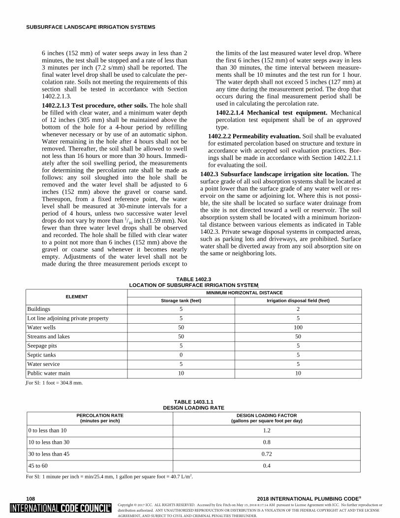
SUBSURFACE LANDSCAPE IRRIGATION SYSTEMS
108 2018 INTERNATIONAL PLUMBING CODE®
6 inches (152 mm) of water seeps away in less than 2minutes, the test shall be stopped and a rate of less than3 minutes per inch (7.2 s/mm) shall be reported. Thefinal water level drop shall be used to calculate the per-colation rate. Soils not meeting the requirements of thissection shall be tested in accordance with Section1402.2.1.3.
1402.2.1.3 Test procedure, other soils. The hole shallbe filled with clear water, and a minimum water depthof 12 inches (305 mm) shall be maintained above thebottom of the hole for a 4-hour period by refillingwhenever necessary or by use of an automatic siphon.Water remaining in the hole after 4 hours shall not beremoved. Thereafter, the soil shall be allowed to swellnot less than 16 hours or more than 30 hours. Immedi-ately after the soil swelling period, the measurementsfor determining the percolation rate shall be made asfollows: any soil sloughed into the hole shall beremoved and the water level shall be adjusted to 6inches (152 mm) above the gravel or coarse sand.Thereupon, from a fixed reference point, the waterlevel shall be measured at 30-minute intervals for aperiod of 4 hours, unless two successive water leveldrops do not vary by more than 1/16 inch (1.59 mm). Notfewer than three water level drops shall be observedand recorded. The hole shall be filled with clear waterto a point not more than 6 inches (152 mm) above thegravel or coarse sand whenever it becomes nearlyempty. Adjustments of the water level shall not bemade during the three measurement periods except to
the limits of the last measured water level drop. Wherethe first 6 inches (152 mm) of water seeps away in lessthan 30 minutes, the time interval between measure-ments shall be 10 minutes and the test run for 1 hour.The water depth shall not exceed 5 inches (127 mm) atany time during the measurement period. The drop thatoccurs during the final measurement period shall beused in calculating the percolation rate.
1402.2.1.4 Mechanical test equipment. Mechanicalpercolation test equipment shall be of an approvedtype.
1402.2.2 Permeability evaluation. Soil shall be evaluatedfor estimated percolation based on structure and texture inaccordance with accepted soil evaluation practices. Bor-ings shall be made in accordance with Section 1402.2.1.1for evaluating the soil.
1402.3 Subsurface landscape irrigation site location. Thesurface grade of all soil absorption systems shall be located ata point lower than the surface grade of any water well or res-ervoir on the same or adjoining lot. Where this is not possi-ble, the site shall be located so surface water drainage fromthe site is not directed toward a well or reservoir. The soilabsorption system shall be located with a minimum horizon-tal distance between various elements as indicated in Table1402.3. Private sewage disposal systems in compacted areas,such as parking lots and driveways, are prohibited. Surfacewater shall be diverted away from any soil absorption site onthe same or neighboring lots.
TABLE 1402.3LOCATION OF SUBSURFACE IRRIGATION SYSTEM
For SI: 1 foot = 304.8 mm.
ELEMENTMINIMUM HORIZONTAL DISTANCE
Storage tank (feet) Irrigation disposal field (feet)
Buildings 5 2
Lot line adjoining private property 5 5
Water wells 50 100
Streams and lakes 50 50
Seepage pits 5 5
Septic tanks 0 5
Water service 5 5
Public water main 10 10
TABLE 1403.1.1DESIGN LOADING RATE
For SI: 1 minute per inch = min/25.4 mm, 1 gallon per square foot = 40.7 L/m2.
PERCOLATION RATE(minutes per inch)
DESIGN LOADING FACTOR(gallons per square foot per day)
0 to less than 10 1.2
10 to less than 30 0.8
30 to less than 45 0.72
45 to 60 0.4
Copyright © 2017 ICC. ALL RIGHTS RESERVED. Accessed by Eric Fitch on May 15, 2018 8:17:14 AM pursuant to License Agreement with ICC. No further reproduction ordistribution authorized. ANY UNAUTHORIZED REPRODUCTION OR DISTRIBUTION IS A VIOLATION OF THE FEDERAL COPYRIGHT ACT AND THE LICENSEAGREEMENT, AND SUBJECT TO CIVIL AND CRIMINAL PENALTIES THEREUNDER.
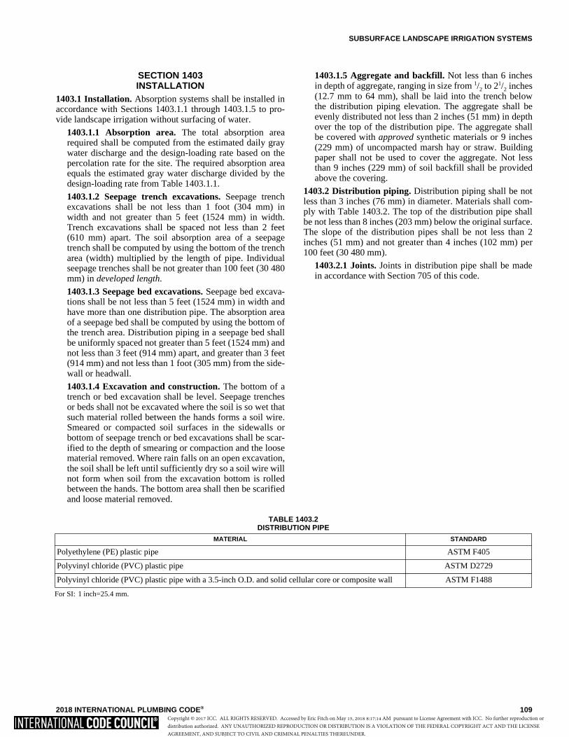
SUBSURFACE LANDSCAPE IRRIGATION SYSTEMS
2018 INTERNATIONAL PLUMBING CODE® 109
SECTION 1403INSTALLATION
1403.1 Installation. Absorption systems shall be installed inaccordance with Sections 1403.1.1 through 1403.1.5 to pro-vide landscape irrigation without surfacing of water.
1403.1.1 Absorption area. The total absorption arearequired shall be computed from the estimated daily graywater discharge and the design-loading rate based on thepercolation rate for the site. The required absorption areaequals the estimated gray water discharge divided by thedesign-loading rate from Table 1403.1.1.
1403.1.2 Seepage trench excavations. Seepage trenchexcavations shall be not less than 1 foot (304 mm) inwidth and not greater than 5 feet (1524 mm) in width.Trench excavations shall be spaced not less than 2 feet(610 mm) apart. The soil absorption area of a seepagetrench shall be computed by using the bottom of the trencharea (width) multiplied by the length of pipe. Individualseepage trenches shall be not greater than 100 feet (30 480mm) in developed length.
1403.1.3 Seepage bed excavations. Seepage bed excava-tions shall be not less than 5 feet (1524 mm) in width andhave more than one distribution pipe. The absorption areaof a seepage bed shall be computed by using the bottom ofthe trench area. Distribution piping in a seepage bed shallbe uniformly spaced not greater than 5 feet (1524 mm) andnot less than 3 feet (914 mm) apart, and greater than 3 feet(914 mm) and not less than 1 foot (305 mm) from the side-wall or headwall.
1403.1.4 Excavation and construction. The bottom of atrench or bed excavation shall be level. Seepage trenchesor beds shall not be excavated where the soil is so wet thatsuch material rolled between the hands forms a soil wire.Smeared or compacted soil surfaces in the sidewalls orbottom of seepage trench or bed excavations shall be scar-ified to the depth of smearing or compaction and the loosematerial removed. Where rain falls on an open excavation,the soil shall be left until sufficiently dry so a soil wire willnot form when soil from the excavation bottom is rolledbetween the hands. The bottom area shall then be scarifiedand loose material removed.
1403.1.5 Aggregate and backfill. Not less than 6 inchesin depth of aggregate, ranging in size from 1/2 to 21/2 inches(12.7 mm to 64 mm), shall be laid into the trench belowthe distribution piping elevation. The aggregate shall beevenly distributed not less than 2 inches (51 mm) in depthover the top of the distribution pipe. The aggregate shallbe covered with approved synthetic materials or 9 inches(229 mm) of uncompacted marsh hay or straw. Buildingpaper shall not be used to cover the aggregate. Not lessthan 9 inches (229 mm) of soil backfill shall be providedabove the covering.
1403.2 Distribution piping. Distribution piping shall be notless than 3 inches (76 mm) in diameter. Materials shall com-ply with Table 1403.2. The top of the distribution pipe shallbe not less than 8 inches (203 mm) below the original surface.The slope of the distribution pipes shall be not less than 2inches (51 mm) and not greater than 4 inches (102 mm) per100 feet (30 480 mm).
1403.2.1 Joints. Joints in distribution pipe shall be madein accordance with Section 705 of this code.
TABLE 1403.2DISTRIBUTION PIPE
For SI: 1 inch=25.4 mm.
MATERIAL STANDARD
Polyethylene (PE) plastic pipe ASTM F405
Polyvinyl chloride (PVC) plastic pipe ASTM D2729
Polyvinyl chloride (PVC) plastic pipe with a 3.5-inch O.D. and solid cellular core or composite wall ASTM F1488
Copyright © 2017 ICC. ALL RIGHTS RESERVED. Accessed by Eric Fitch on May 15, 2018 8:17:14 AM pursuant to License Agreement with ICC. No further reproduction ordistribution authorized. ANY UNAUTHORIZED REPRODUCTION OR DISTRIBUTION IS A VIOLATION OF THE FEDERAL COPYRIGHT ACT AND THE LICENSEAGREEMENT, AND SUBJECT TO CIVIL AND CRIMINAL PENALTIES THEREUNDER.

110 2018 INTERNATIONAL PLUMBING CODE®
Copyright © 2017 ICC. ALL RIGHTS RESERVED. Accessed by Eric Fitch on May 15, 2018 8:17:14 AM pursuant to License Agreement with ICC. No further reproduction ordistribution authorized. ANY UNAUTHORIZED REPRODUCTION OR DISTRIBUTION IS A VIOLATION OF THE FEDERAL COPYRIGHT ACT AND THE LICENSEAGREEMENT, AND SUBJECT TO CIVIL AND CRIMINAL PENALTIES THEREUNDER.
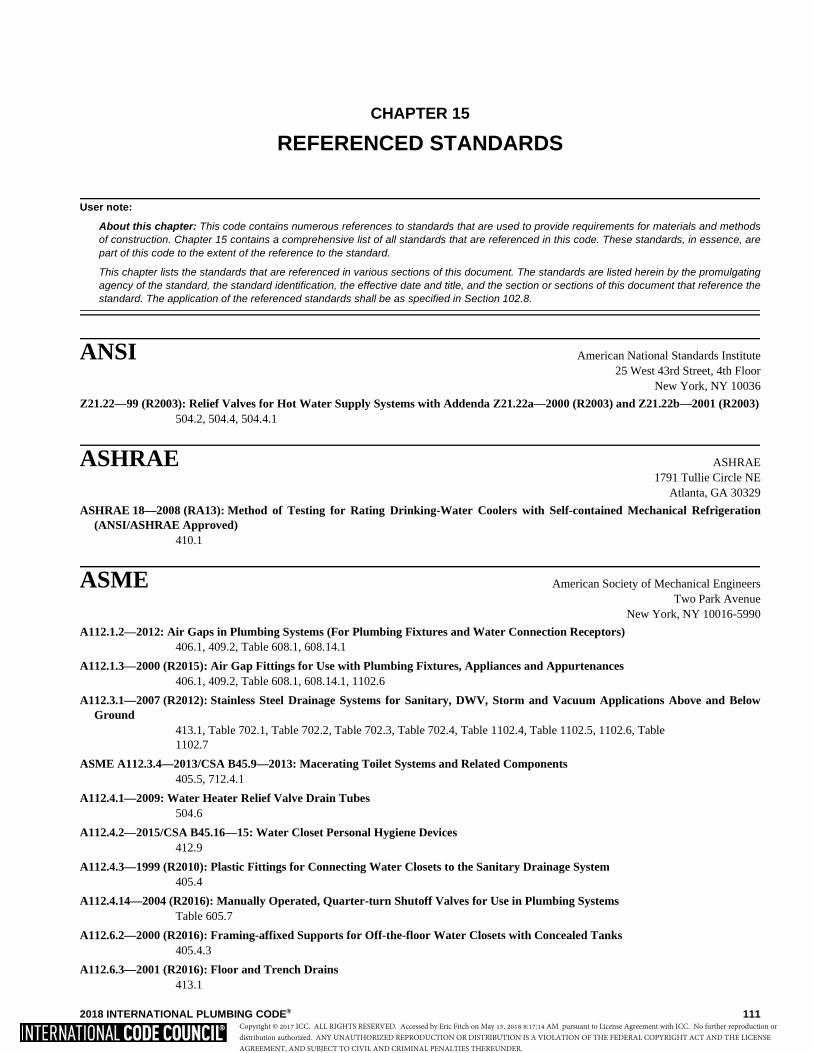
2018 INTERNATIONAL PLUMBING CODE® 111
CHAPTER 15
REFERENCED STANDARDS
User note:
About this chapter: This code contains numerous references to standards that are used to provide requirements for materials and methodsof construction. Chapter 15 contains a comprehensive list of all standards that are referenced in this code. These standards, in essence, arepart of this code to the extent of the reference to the standard.
This chapter lists the standards that are referenced in various sections of this document. The standards are listed herein by the promulgatingagency of the standard, the standard identification, the effective date and title, and the section or sections of this document that reference thestandard. The application of the referenced standards shall be as specified in Section 102.8.
ANSI American National Standards Institute25 West 43rd Street, 4th Floor
New York, NY 10036
Z21.22—99 (R2003): Relief Valves for Hot Water Supply Systems with Addenda Z21.22a—2000 (R2003) and Z21.22b—2001 (R2003)504.2, 504.4, 504.4.1
ASHRAE ASHRAE1791 Tullie Circle NE
Atlanta, GA 30329
ASHRAE 18—2008 (RA13): Method of Testing for Rating Drinking-Water Coolers with Self-contained Mechanical Refrigeration(ANSI/ASHRAE Approved)
410.1
ASME American Society of Mechanical EngineersTwo Park Avenue
New York, NY 10016-5990
A112.1.2—2012: Air Gaps in Plumbing Systems (For Plumbing Fixtures and Water Connection Receptors)406.1, 409.2, Table 608.1, 608.14.1
A112.1.3—2000 (R2015): Air Gap Fittings for Use with Plumbing Fixtures, Appliances and Appurtenances406.1, 409.2, Table 608.1, 608.14.1, 1102.6
A112.3.1—2007 (R2012): Stainless Steel Drainage Systems for Sanitary, DWV, Storm and Vacuum Applications Above and BelowGround
413.1, Table 702.1, Table 702.2, Table 702.3, Table 702.4, Table 1102.4, Table 1102.5, 1102.6, Table1102.7
ASME A112.3.4—2013/CSA B45.9—2013: Macerating Toilet Systems and Related Components405.5, 712.4.1
A112.4.1—2009: Water Heater Relief Valve Drain Tubes504.6
A112.4.2—2015/CSA B45.16—15: Water Closet Personal Hygiene Devices412.9
A112.4.3—1999 (R2010): Plastic Fittings for Connecting Water Closets to the Sanitary Drainage System405.4
A112.4.14—2004 (R2016): Manually Operated, Quarter-turn Shutoff Valves for Use in Plumbing SystemsTable 605.7
A112.6.2—2000 (R2016): Framing-affixed Supports for Off-the-floor Water Closets with Concealed Tanks405.4.3
A112.6.3—2001 (R2016): Floor and Trench Drains413.1
Copyright © 2017 ICC. ALL RIGHTS RESERVED. Accessed by Eric Fitch on May 15, 2018 8:17:14 AM pursuant to License Agreement with ICC. No further reproduction ordistribution authorized. ANY UNAUTHORIZED REPRODUCTION OR DISTRIBUTION IS A VIOLATION OF THE FEDERAL COPYRIGHT ACT AND THE LICENSEAGREEMENT, AND SUBJECT TO CIVIL AND CRIMINAL PENALTIES THEREUNDER.
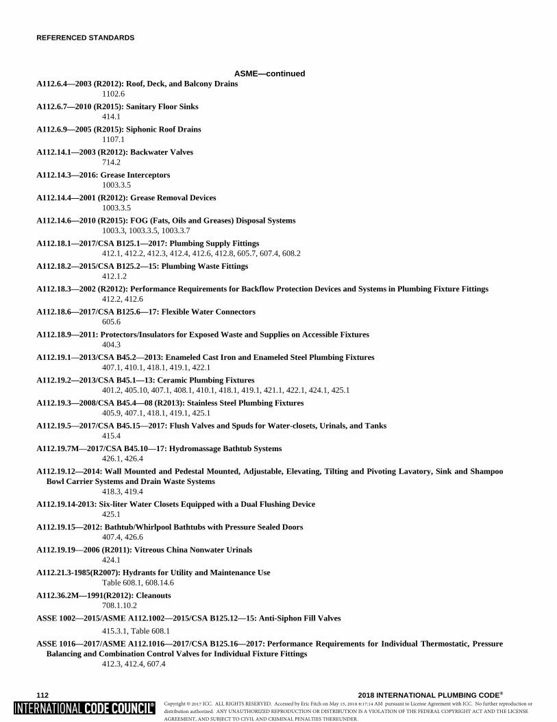
REFERENCED STANDARDS
112 2018 INTERNATIONAL PLUMBING CODE®
ASME—continuedA112.6.4—2003 (R2012): Roof, Deck, and Balcony Drains
1102.6
A112.6.7—2010 (R2015): Sanitary Floor Sinks414.1
A112.6.9—2005 (R2015): Siphonic Roof Drains1107.1
A112.14.1—2003 (R2012): Backwater Valves714.2
A112.14.3—2016: Grease Interceptors 1003.3.5
A112.14.4—2001 (R2012): Grease Removal Devices1003.3.5
A112.14.6—2010 (R2015): FOG (Fats, Oils and Greases) Disposal Systems1003.3, 1003.3.5, 1003.3.7
A112.18.1—2017/CSA B125.1—2017: Plumbing Supply Fittings412.1, 412.2, 412.3, 412.4, 412.6, 412.8, 605.7, 607.4, 608.2
A112.18.2—2015/CSA B125.2—15: Plumbing Waste Fittings412.1.2
A112.18.3—2002 (R2012): Performance Requirements for Backflow Protection Devices and Systems in Plumbing Fixture Fittings412.2, 412.6
A112.18.6—2017/CSA B125.6—17: Flexible Water Connectors605.6
A112.18.9—2011: Protectors/Insulators for Exposed Waste and Supplies on Accessible Fixtures404.3
A112.19.1—2013/CSA B45.2—2013: Enameled Cast Iron and Enameled Steel Plumbing Fixtures 407.1, 410.1, 418.1, 419.1, 422.1
A112.19.2—2013/CSA B45.1—13: Ceramic Plumbing Fixtures401.2, 405.10, 407.1, 408.1, 410.1, 418.1, 419.1, 421.1, 422.1, 424.1, 425.1
A112.19.3—2008/CSA B45.4—08 (R2013): Stainless Steel Plumbing Fixtures405.9, 407.1, 418.1, 419.1, 425.1
A112.19.5—2017/CSA B45.15—2017: Flush Valves and Spuds for Water-closets, Urinals, and Tanks415.4
A112.19.7M—2017/CSA B45.10—17: Hydromassage Bathtub Systems426.1, 426.4
A112.19.12—2014: Wall Mounted and Pedestal Mounted, Adjustable, Elevating, Tilting and Pivoting Lavatory, Sink and ShampooBowl Carrier Systems and Drain Waste Systems
418.3, 419.4
A112.19.14-2013: Six-liter Water Closets Equipped with a Dual Flushing Device425.1
A112.19.15—2012: Bathtub/Whirlpool Bathtubs with Pressure Sealed Doors407.4, 426.6
A112.19.19—2006 (R2011): Vitreous China Nonwater Urinals424.1
A112.21.3-1985(R2007): Hydrants for Utility and Maintenance UseTable 608.1, 608.14.6
A112.36.2M—1991(R2012): Cleanouts708.1.10.2
ASSE 1002—2015/ASME A112.1002—2015/CSA B125.12—15: Anti-Siphon Fill Valves
415.3.1, Table 608.1
ASSE 1016—2017/ASME A112.1016—2017/CSA B125.16—2017: Performance Requirements for Individual Thermostatic, PressureBalancing and Combination Control Valves for Individual Fixture Fittings
412.3, 412.4, 607.4
Copyright © 2017 ICC. ALL RIGHTS RESERVED. Accessed by Eric Fitch on May 15, 2018 8:17:14 AM pursuant to License Agreement with ICC. No further reproduction ordistribution authorized. ANY UNAUTHORIZED REPRODUCTION OR DISTRIBUTION IS A VIOLATION OF THE FEDERAL COPYRIGHT ACT AND THE LICENSEAGREEMENT, AND SUBJECT TO CIVIL AND CRIMINAL PENALTIES THEREUNDER.
REFERENCED STANDARDS
2018 INTERNATIONAL PLUMBING CODE® 113
ASME—continuedASSE 1037—2015/ASME A112.1037—2015/CSA B125.37—: Pressurized Flushing Devices for Plumbing Fixtures
415.2
ASSE 1070—2015/ASME A112.1070—2015/CSA B125.1070—15: Water Temperature Limiting Devices408.3, 412.5, 412.10, 419.5, 423.3, 607.1.2
B1.20.1—2013: Pipe Threads, General Purpose (inch)605.10.3, 605.12.4, 605.14.3, 605.17.1, 605.22.4, 705.2.3, 705.5.4, 705.8.1, 705.10.3, 705.19.1
B16.3—2016: Malleable Iron Threaded Fittings Classes 150 and 300Table 1102.7
B16.4—2016: Gray Iron Threaded Fittings Classes 125 and 250Table 605.5, Table 702.4, Table 1102.7
B16.9—2012: Factory-made Wrought Steel Buttwelding FittingsTable 605.5, Table 702.4, Table 1102.7
B16.11—2016: Forged Fittings, Socket-welding and ThreadedTable 605.5, Table 702.4, Table 1102.7
B16.12—2009 (R2014): Cast-iron Threaded Drainage FittingsTable 702.4, Table 1102.7
B16.15—2013: Cast Alloy Threaded Fittings: Class 125 and 250Table 605.5, Table 702.4, Table 1102.7
B16.18—2012: Cast Copper Alloy Solder Joint Pressure FittingsTable 605.5, Table 702.4, Table 1102.7
B16.22—2013: Wrought Copper and Copper Alloy Solder Joint Pressure FittingsTable 605.5, Table 702.4, Table 1102.7
B16.23—2016: Cast Copper Alloy Solder Joint Drainage Fittings DWVTable 702.4, Table 1102.7
B16.26—2016: Cast Copper Alloy Fittings for Flared Copper TubesTable 605.5, Table 702.4, Table 1102.7
B16.28—1994: Wrought Steel Buttwelding Short Radius Elbows and ReturnsTable 605.5, Table 702.4, Table 1102.7
B16.29—2012: Wrought Copper and Wrought Copper Alloy Solder Joint Drainage Fittings (DWV)Table 702.4, Table 1102.7
B16.34—2015: Valves Flanged, Threaded and Welding EndTable 605.7
B16.51—2013: Copper and Copper Alloy Press-connect Pressure FittingsTable 605.5
ASPE American Society of Plumbing Engineers6400 Shafer Ct., Suite 350Rosemont, IL 60018-4914
45—2013: Siphonic Roof Drainage Systems1107.1
ASSE ASSE International18927 Hickory Creek Drive, Suite 220
Mokena, IL 60448
1001—2016: Performance Requirements for Atmospheric Type Vacuum Breakers415.2, Table 608.1, 608.14.6, 608.17.4.1
ASSE 1002—2015/ASME A112.1002—2015/CSA B125.12—15: Antisiphon Fill Valves415.3.1, Table 608.1
1003—09: Performance Requirements for Water Pressure Reducing Valves604.8
1004—2016: Performance Requirements for Commercial Dishwashing Machines409.1
Copyright © 2017 ICC. ALL RIGHTS RESERVED. Accessed by Eric Fitch on May 15, 2018 8:17:14 AM pursuant to License Agreement with ICC. No further reproduction ordistribution authorized. ANY UNAUTHORIZED REPRODUCTION OR DISTRIBUTION IS A VIOLATION OF THE FEDERAL COPYRIGHT ACT AND THE LICENSEAGREEMENT, AND SUBJECT TO CIVIL AND CRIMINAL PENALTIES THEREUNDER.
REFERENCED STANDARDS
114 2018 INTERNATIONAL PLUMBING CODE®
ASSE—continued1005—99: Performance Requirements for Water Heater Drain Valves
501.3
1008—06: Performance Requirements for Plumbing Aspects of Food Waste Disposer Units413.1
1010—04: Performance Requirements for Water Hammer Arresters604.9
1011—2016: Performance Requirements for Hose Connection Vacuum BreakersTable 608.1, 608.14.6
1012—09: Performance Requirements for Backflow Preventers with Intermediate Atmospheric VentTable 608.1, 608.14.3, 608.17.2, 608.17.10
1013—2017: Performance Requirements for Reduced Pressure Principle Backflow Preventers and Reduced Pressure Principle FireProtection Backflow Preventers
Table 608.1, 608.14.2, 608.17.2
1015—2017: Performance Requirements for Double Check Backflow Prevention Assemblies and Double Check Fire ProtectionBackflow Prevention Assemblies
Table 608.1, 608.14.7
ASSE 1016—2017/ASME A112.1016—2017/CSA B125.16—2017: Performance Requirements for Individual Thermostatic, PressureBalancing and Combination Control Valves for Individual Fixture Fittings
412.3, 412.4, 607.4
1017—2010: Performance Requirements for Temperature Actuated Mixing Valves for Hot Water Distribution Systems501.2, 613.1
1018—2017: Performance Requirements for Trap Seal Primer Valves; Potable Water Supplied1002.4.1.2
1019—2016: Performance Requirements for Vacuum Breaker Wall Hydrants, Freeze Resistant, Automatic Draining TypeTable 608.1, 608.14.6
1020—04: Performance Requirements for Pressure Vacuum Breaker AssemblyTable 608.1, 608.14.5
1022—2016: Performance Requirements for Backflow Preventer for Beverage Dispensing EquipmentTable 608.1, 608.17.1.1, 608.17.1.2
1024—2016: Performance Requirements for Dual Check Valve Type Backflow Preventers, Anti-siphon-type, Residential Applications605.3.1, Table 608.1, 608.14.9, 608.17.1.2
1035—08: Performance Requirements for Laboratory Faucet Backflow PreventersTable 608.1, 608.14.6
ASSE 1037—2015/ASME A112.1037—2015/CSA B125.37—15: Pressurized Flushing Devices for Plumbing Fixtures415.2
1044—2010: Performance Requirements for Trap Seal Primer Devices Drainage Types and Electronic Design Types1002.4.1.3
1047—2017: Performance Requirements for Reduced Pressure Detector Fire Protection Backflow Prevention AssembliesTable 608.1, 608.14.2
1048—2017: Performance Requirements for Double Check Detector Fire Protection Backflow Prevention AssembliesTable 608.1, 608.14.7
1049—2009: Performance Requirements for Individual and Branch Type Air Admittance Valves for Chemical Waste Systems901.3, 918.8
1050—2009: Performance Requirements for Stack Air Admittance Valves for Sanitary Drainage Systems918.1
1051—2009: Performance Requirements for Individual and Branch Type Air Admittance Valves for Sanitary Drainage Systems-fixture and Branch Devices
918.1
1052—2016: Performance Requirements for Hose Connection Backflow PreventersTable 608.1, 608.14.6
1055—2016: Performance Requirements for Chemical Dispensing Systems608.14.8
Copyright © 2017 ICC. ALL RIGHTS RESERVED. Accessed by Eric Fitch on May 15, 2018 8:17:14 AM pursuant to License Agreement with ICC. No further reproduction ordistribution authorized. ANY UNAUTHORIZED REPRODUCTION OR DISTRIBUTION IS A VIOLATION OF THE FEDERAL COPYRIGHT ACT AND THE LICENSEAGREEMENT, AND SUBJECT TO CIVIL AND CRIMINAL PENALTIES THEREUNDER.
REFERENCED STANDARDS
2018 INTERNATIONAL PLUMBING CODE® 115
ASSE—continued1056—2013: Performance Requirements for Spill Resistant Vacuum Breaker
Table 608.1, 608.14.5
1060—2016: Performance Requirements for Outdoor Enclosures for Fluid Conveying Components608.15.1
1061—2015: Performance Requirements for Push Fit FittingsTable 605.5, 604.13.7, 605.14.4, 605.16.3
1062—2016: Performance Requirements for Temperature Actuated, Flow Reduction (TAFR) Valves to Individual Supply Fittings424.7
1066—2016: Performance Requirements for Individual Pressure Balancing In-line Valves for Individual Fixture Fittings604.11
1069—05: Performance Requirements for Automatic Temperature Control Mixing Valves412.4
ASSE 1070—2015/ASME A112.1070—2015/CSA B125.70—15: Water-temperature Limiting Devices408.3, 419.5, 423.3, 424.5, 607.1.2
1071—2012: Performance Requirements for Temperature Actuated Mixing Valves for Plumbed Emergency Equipment411.3, 412.5, 412.10, 419.5, 423.3, 607.1.2
1072—07: Performance Requirements for Barrier Type Floor Drain Tap Seal Protection Devices1002.4.14
1079—2005: Performance Requirements for Dielectric Pipe Unions605.23.1, 605.23.3
5013—2015: Performance Requirements for Testing Reduced Pressure Principle Backflow Prevention Assembly (RPA) and ReducedPressure Fire Protection Backflow Preventers (RFP)
312.10.2
5015—2015: Performance Requirements for Testing Double Check Valve Backflow Prevention Assemblies (DC) and Double CheckFire Protection Backflow Prevention Assemblies (DCF)
312.10.2
5020—2015: Performance Requirements for Testing Pressure Vacuum Breaker Assemblies (PVBA)312.10.2
5047—2015: Performance Requirements for Testing Reduced Pressure Detector Fire Protection Backflow Prevention Assemblies(RPDA)
312.10.2
5048—2015: Performance Requirements for Testing Double Check Valve Detector Assembly (DCDA)312.10.2
5052—98: Performance Requirements for Testing Hose Connection Backflow Preventers312.10.2
5056—2015: Performance Requirements for Testing Spill Resistant Vacuum Breaker (SRVB)312.10.2
ASTM ASTM International100 Barr Harbor Drive, P.O. Box C700
West Conshohocken, PA 19428-2959
A53/A53M—12: Specification for Pipe, Steel, Black and Hot-dipped, Zinc-coated Welded and SeamlessTable 605.3, Table 605.4, Table 702.1
A74—15: Specification for Cast-iron Soil Pipe and FittingsTable 702.1, Table 702.2, Table 702.3, Table 702.4, 708.1.6, 708.7, Table 1102.4, Table 1102.5, Table1102.7
A312/A312M—15a: Specification for Seamless, Welded, and Heavily Cold Worked Austenitic Stainless Steel PipesTable 605.3, Table 605.4, Table 605.5, 605.22.2
A733—15: Specification for Welded and Seamless Carbon Steel and Austenitic Stainless Steel Pipe NipplesTable 605.8
A778/A778M—15: Specification for Welded Unannealed Austenitic Stainless Steel Tubular ProductsTable 605.3, Table 605.4, Table 605.5
Copyright © 2017 ICC. ALL RIGHTS RESERVED. Accessed by Eric Fitch on May 15, 2018 8:17:14 AM pursuant to License Agreement with ICC. No further reproduction ordistribution authorized. ANY UNAUTHORIZED REPRODUCTION OR DISTRIBUTION IS A VIOLATION OF THE FEDERAL COPYRIGHT ACT AND THE LICENSEAGREEMENT, AND SUBJECT TO CIVIL AND CRIMINAL PENALTIES THEREUNDER.
REFERENCED STANDARDS
116 2018 INTERNATIONAL PLUMBING CODE®
ASTM—continuedA888—15: Specification for Hubless Cast-iron Soil Pipe and Fittings for Sanitary and Storm Drain, Waste, and Vent Piping
ApplicationTable 702.1, Table 702.2, Table 702.3, Table 702.4, 708.7, Table 1102.4, Table 1102.5, Table 1102.7
B32—08(2014): Specification for Solder Metal605.12.3, 605.13.6, 705.5.3, 705.6.1, 705.17.3
B42—15a: Specification for Seamless Copper Pipe, Standard SizesTable 605.3, Table 605.4, Table 702.1
B43—15: Specification for Seamless Red Brass Pipe, Standard SizesTable 605.4, Table 702.1
B75/B75M—11: Specification for Seamless Copper TubeTable 605.3, Table 605.4, Table 702.1, Table 702.2, Table 702.3, Table 1102.4
B88—14: Specification for Seamless Copper Water TubeTable 605.3, Table 605.4, Table 702.1, Table 702.2, Table 702.3, Table 1102.4
B152/B152M—13: Specification for Copper Sheet, Strip Plate and Rolled Bar402.3, 415.3.3, 422.5.2.4, 902.2
B251—10: Specification for General Requirements for Wrought Seamless Copper and Copper-alloy TubeTable 605.3, Table 605.4, Table 702.1, Table 702.2, Table 702.3, Table 1102.4
B302—12: Specification for Threadless Copper Pipe, Standard SizesTable 605.3, Table 605.4, Table 702.1
B306—13: Specification for Copper Drainage Tube (DWV)Table 702.1, Table 702.2, Table 1102.4
B447—12a: Specification for Welded Copper TubeTable 605.3, Table 605.4
B687—99(2011): Specification for Brass, Copper and Chromium-plated Pipe NipplesTable 605.8
B813—10: Specification for Liquid and Paste Fluxes for Soldering of Copper and Copper Alloy Tube605.12.3, 605.13.6, 705.5.3, 705.6.1, 705.7.3
B828—02(2010): Practice for Making Capillary Joints by Soldering of Copper and Copper Alloy Tube and Fittings605.12.3, 605.13.6, 705.5.3, 705.6.1, 705.17.3
C4—04(2014): Specification for Clay Drain Tile and Perforated Clay Drain TileTable 702.3, Table 1102.4, Table 1102.5
C14—15a: Specification for Nonreinforced Concrete Sewer, Storm Drain and Culvert PipeTable 702.3, Table 1102.4
C76—15a: Specification for Reinforced Concrete Culvert, Storm Drain and Sewer PipeTable 702.3, Table 1102.4
C425—04(2013): Specification for Compression Joints for Vitrified Clay Pipe and Fittings705.11, 705.16
C443—12: Specification for Joints for Concrete Pipe and Manholes, Using Rubber Gaskets705.4, 705.16
C564—14: Specification for Rubber Gaskets for Cast-iron Soil Pipe and Fittings705.3.2, 705.3.3, 705.16
C700—13: Specification for Vitrified Clay Pipe, Extra Strength, Standard Strength, and PerforatedTable 702.3, Table 702.4, Table 1102.4, Table 1102.5
C1053—00(2010): Specification for Borosilicate Glass Pipe and Fittings for Drain, Waste, and Vent (DWV) ApplicationsTable 702.1, Table 702.4
C1173—10(2014): Specification for Flexible Transition Couplings for Underground Piping System705.2.1, 705.5, 705.10.1, 705.11, 705.12.2, 705.16
C1277—15: Specification for Shielded Coupling Joining Hubless Cast-iron Soil Pipe and Fittings705.3.3
C1440—08(2013): Specification for Thermoplastic Elastomeric (TPE) Gasket Materials for Drain, Waste, and Vent (DWV), Sewer,Sanitary and Storm Plumbing Systems
705.16
Copyright © 2017 ICC. ALL RIGHTS RESERVED. Accessed by Eric Fitch on May 15, 2018 8:17:14 AM pursuant to License Agreement with ICC. No further reproduction ordistribution authorized. ANY UNAUTHORIZED REPRODUCTION OR DISTRIBUTION IS A VIOLATION OF THE FEDERAL COPYRIGHT ACT AND THE LICENSEAGREEMENT, AND SUBJECT TO CIVIL AND CRIMINAL PENALTIES THEREUNDER.

REFERENCED STANDARDS
2018 INTERNATIONAL PLUMBING CODE® 117
ASTM—continuedC1460—2012: Specification for Shielded Transition Couplings for Use with Dissimilar DWV Pipe and Fittings Above Ground
705.16
C1461—08(2013): Specification for Mechanical Couplings Using Thermoplastic Elastomeric (TPE) Gaskets for Joining Drain, Wasteand Vent (DWV) Sewer, Sanitary and Storm Plumbing Systems for Above and Below Ground Use
705.19
C1540—15: Specification for Heavy Duty Shielded Couplings Joining Hubless Cast-iron Soil Pipe and Fittings705.3.3
C1563—08(2013): Standard Test Method for Gaskets for Use in Connection with Hub and Spigot Cast Iron Soil Pipe and Fittings forSanitary Drain, Waste, Vent and Storm Piping Applications
705.3.2
D1253—14: Standard Test Method For Residual Chlorine in Water1301.2.1, 1303.9
D1527—99(2005): Specification for Acrylonitrile-Butadiene-Styrene (ABS) Plastic Pipe, Schedules 40 and 80Table 605.3
D1785—15: Specification for Poly (Vinyl Chloride) (PVC) Plastic Pipe, Schedules 40, 80 and 120Table 605.3
D2235—04(2011): Specification for Solvent Cement for Acrylonitrile-Butadiene-Styrene (ABS) Plastic Pipe and Fittings605.10.2, 705.2.2, 705.7.2
D2239—12a: Specification for Polyethylene (PE) Plastic Pipe (SIDR-PR) Based on Controlled Inside DiameterTable 605.3
D2241—15: Specification for Poly (Vinyl Chloride) (PVC) Pressure-rated Pipe (SDR-Series)Table 605.3
D2282—99(2005): Specification for Acrylonitrile-Butadiene-Styrene (ABS) Plastic Pipe (SDR-PR)Table 605.3
D2464—15: Specification for Threaded Poly (Vinyl Chloride) (PVC) Plastic Pipe Fittings, Schedule 80Table 605.5, 605.21.3
D2466—15: Specification for Poly (Vinyl Chloride) (PVC) Plastic Pipe Fittings, Schedule 40Table 605.5
D2467—15: Specification for Poly (Vinyl Chloride) (PVC) Plastic Pipe Fittings, Schedule 80Table 605.5
D2468—96a: Specification for Acrylonitrile-Butadiene-Styrene (ABS) Plastic Pipe Fittings, Schedule 40Table 605.5
D2564—12: Specification for Solvent Cements for Poly (Vinyl Chloride) (PVC) Plastic Piping Systems605.21.3, 705.10.2, 705.14.2
D2609—15: Specification for Plastic Insert Fittings for Polyethylene (PE) Plastic PipeTable 605.5
D2657—07: Practice for Heat Fusion-joining of Polyolefin Pipe and Fitting Waste, and Vent Pipe and Fittings605.18.2, 705.12.1
D2661—14: Specification for Acrylonitrile-Butadiene-Styrene (ABS) Schedule 40 Plastic Drain, Waste, and Vent Pipe and FittingsTable 702.1, Table 702.2, Table 702.3, Table 702.4, 705.2.2, 705.7.2, Table 1102.4, Table 1102.7
D2665—14: Specification for Poly (Vinyl Chloride) (PVC) Plastic Drain, Waste, and Vent Pipe and FittingsTable 702.1, Table 702.2, Table 702.3, Table 702.4, Table 1102.4, Table 1102.7
D2672—14: Specification for Joints for IPS PVC Pipe Using Solvent CementTable 605.3
D2683—14: Standard Specification for Socket-type Polyethylene Fittings for Outside Diameter-controlled Polyethylene Pipe andTubing
Table 605.5, Table 702.4, 716.5
D2729—11: Specification for Poly (Vinyl Chloride) (PVC) Sewer Pipe and FittingsTable 1102.5, Table 1403.2
D2737—2012a: Specification for Polyethylene (PE) Plastic TubingTable 605.3
D2751—05: Specification for Acrylonitrile-Butadiene-Styrene (ABS) Sewer Pipe and FittingsTable 702.3, Table 702.4, Table 1102.7
Copyright © 2017 ICC. ALL RIGHTS RESERVED. Accessed by Eric Fitch on May 15, 2018 8:17:14 AM pursuant to License Agreement with ICC. No further reproduction ordistribution authorized. ANY UNAUTHORIZED REPRODUCTION OR DISTRIBUTION IS A VIOLATION OF THE FEDERAL COPYRIGHT ACT AND THE LICENSEAGREEMENT, AND SUBJECT TO CIVIL AND CRIMINAL PENALTIES THEREUNDER.
REFERENCED STANDARDS
118 2018 INTERNATIONAL PLUMBING CODE®
ASTM—continuedD2846/D2846M—14: Specification for Chlorinated Poly (Vinyl Chloride) (CPVC) Plastic Hot- and Cold-Water Distribution Systems
Table 605.3, Table 605.4, Table 605.5, 605.14.2, 605.15.2
D2855—96(2010): Standard Practice for Making Solvent-cemented Joints with Poly (Vinyl Chloride) (PVC) Pipe and Fittings605.21.3, 705.10.2
D2949—10: Specification for 3.25-in. Outside Diameter Poly (Vinyl Chloride) (PVC) Plastic Drain, Waste, and Vent Pipe and FittingsTable 702.1, Table 702.2, Table 702.3, Table 702.4, Table 1102.7
D3034—14a: Specification for Type PSM Poly (Vinyl Chloride) (PVC) Sewer Pipe and FittingsTable 702.3, Table 702.4, Table 1102.4, Table 1102.5, Table 1102.7
D3035—15: Standard Specification for Polyethylene (PE) Plastic Pipe (DR-PR) Based on Controlled Outside DiameterTable 605.3
D3138—04(2011): Standard Specification for Solvent Cements for Transition Joints Between Acrylonitrile-Butadiene-Styrene (ABS)and Poly (Vinyl Chloride) (PVC) Non-pressure Piping Components
Table 705.16.4
D3139—98(2011): Specification for Joints for Plastic Pressure Pipes Using Flexible Elastomeric Seals605.10.1, 605.22.1
D3212—07(2013): Specification for Joints for Drain and Sewer Plastic Pipes Using Flexible Elastomeric Seals705.2.1, 705.10.1, 705.12.2, 705.15
D3261—12e1: Specification for Butt Heat Fusion Polyethylene (PE) Plastic Fittings for Polyethylene (PE) Plastic Pipe and TubingTable 605.5
D3311—11: Specification for Drain, Waste and Vent (DWV) Plastic Fittings PatternsTable 1102.7
D4068—15: Specification for Chlorinated Polyethlene (CPE) Sheeting for Concealed Water-containment Membrane422.5.2.2
D4551—12: Specification for Poly (Vinyl Chloride) (PVC) Plastic Flexible Concealed Water-containment Membrane421.5.2.1
E2635—14: Standard Practice for Water Conservation Through In-Situ Water Reclamation1302.1
E2727—10e1: Standard Practice for the Assessment of Rainwater Quality1303.15.9
F405—05: Specification for Corrugated Polyethylene (PE) Pipe and FittingsTable 1102.5, Table 1403.2
F409—12: Specification for Thermoplastic Accessible and Replaceable Plastic Tube and Tubular Fittings412.1.2, Table 1102.7
F437—15: Specification for Threaded Chlorinated Poly (Vinyl Chloride) (CPVC) Plastic Pipe Fittings, Schedule 80Table 605.5
F438—15: Specification for Socket-type Chlorinated Poly (Vinyl Chloride) (CPVC) Plastic Pipe Fittings, Schedule 40Table 605.5
F439—13: Standard Specification for Chlorinated Poly (Vinyl Chloride) (CPVC) Plastic Pipe Fittings, Schedule 80Table 605.5
F441/F441M—15: Specification for Chlorinated Poly (Vinyl Chloride) (CPVC) Plastic Pipe,Schedules 40 and 80Table 605.3, Table 605.4
F442/F442M—13e1: Specification for Chlorinated Poly (Vinyl Chloride) (CPVC) Plastic Pipe (SDR-PR)Table 605.3, Table 605.4
F477—14: Specification for Elastomeric Seals (Gaskets) for Joining Plastic Pipe605.23,705.16
F493—14: Specification for Solvent Cements for Chlorinated Poly (Vinyl Chloride) (CPVC) Plastic Pipe and Fittings605.14.2, 605.15.2
F628—12e1: Specification for Acrylonitrile-Butadiene-Styrene (ABS) Schedule 40 Plastic Drain, Waste, and Vent Pipe with a CellularCore
Table 702.1, Table 702.2, Table 702.3, Table 702.4, 705.2.2, Table 1102.4, Table 1102.7
F656—15: Specification for Primers for Use in Solvent Cement Joints of Poly (Vinyl Chloride) (PVC) Plastic Pipe and Fittings605.21.3, 705.10.2, 705.14.2
Copyright © 2017 ICC. ALL RIGHTS RESERVED. Accessed by Eric Fitch on May 15, 2018 8:17:14 AM pursuant to License Agreement with ICC. No further reproduction ordistribution authorized. ANY UNAUTHORIZED REPRODUCTION OR DISTRIBUTION IS A VIOLATION OF THE FEDERAL COPYRIGHT ACT AND THE LICENSEAGREEMENT, AND SUBJECT TO CIVIL AND CRIMINAL PENALTIES THEREUNDER.
REFERENCED STANDARDS
2018 INTERNATIONAL PLUMBING CODE® 119
ASTM—continuedF667—12: Standard Specification for 3 through 24 in. Corrugated Polyethylene Pipe and Fittings
Table 1102.4, Table 1102.5
F714—2013: Specification for Polyethylene (PE) Plastic Pipe (SDR-PR) Based on Outside Diameter Table 702.3, 717.4
F876—15a: Specification for Cross-linked Polyethylene (PEX) TubingTable 605.3, Table 605.4
F877—11a: Specification for Cross-linked Polyethylene (PEX) Hot- and Cold-water Distribution SystemsTable 605.5
F891—10: Specification for Coextruded Poly (Vinyl Chloride) (PVC) Plastic Pipe with a Cellular CoreTable 702.1 Table 702.2, Table 702.3, Table 1102.4, Table 1102.5, Table 1102.7
F1055—13: Standard Specification for Electrofusion Type Polyethylene Fittings for Outside Diameter Controlled Polyethylene andCross-linked Polyethylene Pipe and Tubing
Table 605.5
F1281—11: Specification for Cross-linked Polyethylene/Aluminum/ Cross-linked Polyethylene (PEX-AL-PEX) Pressure PipeTable 605.3, Table 605.4, Table 605.5, 605.20.1
F1282—10: Specification for Polyethylene/Aluminum/Polyethylene (PE-AL-PE) Composite Pressure PipeTable 605.3, Table 605.4, Table 605.5, 605.20.1
F1412—09: Specification for Polyolefin Pipe and Fittings for Corrosive Waste DrainageTable 702.1, Table 702.2, Table 702.4, 705.13.1, 901.3
F1476—07(2013): Standard Specification for Performance of Gasketed Mechanical Couplings for Use in Piping ApplicationsTable 605.5, 605.13.3, 605.17.3, 605.22.2, 605.22.3
F1488—14: Specification for Coextruded Composite PipeTable 702.1, Table 702.2, Table 702.3, Table 1102.4, Table 1403.2
F1548—01(2012): Standard Specification for the Performance of Fittings for Use with Gasketed Mechanical Couplings Used in PipingApplications
Table 605.5
F1673—10: Standard Specification for Polyvinylidene Fluoride (PVDF) Corrosive Waste Drainage SystemsTable 702.1, Table 702.2, Table 702.3, Table 702.4, 705.14.1
F1807—15: Specification for Metal Insert Fittings Utilizing a Copper Crimp Ring for SDR9 Cross-linked Polyethylene (PEX) Tubingand SDR9 Polyethylene of Raised Temperature (PE-RT) Tubing
Table 605.5
F1866—13: Specification for Poly (Vinyl Chloride) (PVC) Plastic Schedule 40 Drainage and DWV Fabricated FittingsTable 702.4, Table 1102.7
F1960—15: Specification for Cold Expansion Fittings with PEX Reinforcing Rings for Use with Cross-linked Polyethylene (PEX)Tubing
Table 605.5
F1970—12e1: Special Engineered Fittings, Appurtenances or Valves for Use in Poly (Vinyl Chloride) (PVC) OR Chlorinated Poly(Vinyl Chloride) (CPVC) Systems
Table 605.7
F1974—09(2015): Specification for Metal Insert Fittings for Polyethylene/Aluminum/Polyethylene and Cross-linked Polyethylene/Aluminum/Cross-linked Polyethylene Composite Pressure Pipe
Table 605.5, 605.20.1
F1986—01(2011): Specification for Multilayer Pipe, Type 2, Compression Fittings and Compression Joints for Hot and Cold DrinkingWater Systems
Table 605.3, Table 605.4, Table 605.5
F2080—15: Specifications for Cold-expansion Fittings with Metal Compression-sleeves for Cross-linked Polyethylene (PEX) PipeTable 605.5
F2098—08: Standard Specification for Stainless Steel Clamps for Securing SDR9 Cross-linked Polyethylene (PEX) Tubing to MetalInsert and Plastic Fittings
Table 605.5
F2159—14: Specification for Plastic Insert Fittings Utilizing a Copper Crimp Ring for SDR9 Cross-linked Polyethylene (PEX) Tubingand SDR9 Polyethylene of Raised Temperature (PE-RT) Tubing
Table 605.5
Copyright © 2017 ICC. ALL RIGHTS RESERVED. Accessed by Eric Fitch on May 15, 2018 8:17:14 AM pursuant to License Agreement with ICC. No further reproduction ordistribution authorized. ANY UNAUTHORIZED REPRODUCTION OR DISTRIBUTION IS A VIOLATION OF THE FEDERAL COPYRIGHT ACT AND THE LICENSEAGREEMENT, AND SUBJECT TO CIVIL AND CRIMINAL PENALTIES THEREUNDER.
REFERENCED STANDARDS
120 2018 INTERNATIONAL PLUMBING CODE®
ASTM—continuedF2262—09: Specification for Cross-linked Polyethylene/Aluminum/Cross-linked Polyethylene Tubing OD Controlled SDR9
Table 605.3, Table 605.4
F2306/F2306M—14e1: 12'' to 60'' Annular Corrugated Profile-wall Polyethylene (PE) Pipe and Fittings for Gravity Flow StormSewer and Subsurface Drainage Applications
Table 1102.4, Table 1102.7
F2389—15: Specification for Pressure-rated Polypropylene (PP) Piping SystemsTable 605.3, Table 605.4, Table 605.5, Table 605.7, 605.19.1
F2434—14: Standard Specification for Plastic Insert Fittings Utilizing a Copper Crimp Ring for SDR9 Cross-linked Polyethylene(PEX) Tubing and SDR9 Cross-linked Polyethylene/Aluminum/ Cross-linked Polyethylene (PEX AL-PEX) Tubing
Table 605.5
F2648/F2648M—13: Standard Specification for 2 to 60 inch [50 to 1500 mm] Annular Corrugated Profile Wall Polyethylene (PE) Pipeand Fittings for Land Drainage Applications
Table 1102.4
F2735—09: Standard Specification for Plastic Insert Fittings for SDR9 Cross-linked Polyethylene (PEX) and Polyethylene of RaisedTemperature (PE-RT) Tubing
Table 605.5
F2736—13e1: Standard Specification for 6 to 30 in. [152 to 762 mm] Polypropylene (PP) Corrugated Single Wall Pipe and DoubleWall Pipe
Table 702.3
F2764/F2764M—11ae2: Standard Specification for 30 to 60 in. [750 to 1500 mm] Polypropylene (PP) Triple Wall Pipe and Fittings forNon-pressure Sanitary Sewer Applications
Table 702.3
F2769—14: Polyethylene or Raised Temperature (PE-RT) Plastic Hot- and Cold-water Tubing and Distribution SystemsTable 605.3, Table 605.4, Table 605.5
F2831—12: Standard Practice for Internal Non Structural Epoxy Barrier Coating Material Used in Rehabilitation of MetallicPressurized Piping Systems
601.5
F2855—12: Standard Specification for Chlorinated Poly (Vinyl Chloride)/Aluminum/Chlorinated Poly (Vinyl Chloride) (CPVC/AL/CPVC) Composite Pressure Tubing
Table 605.3, Table 605.4
F2881—11: Standard Specification for 12 to 60 in. [300 to 1500 mm] Polypropylene (PP) Dual Wall Pipe and Fittings for Non-pressureStorm Sewer Applications
Table 1102.4
AWS American Welding Society8669 NW 36 Street, #130
Miami, FL 33166
A5.8M/A5.8—2011: Specifications for Filler Metals for Brazing and Braze Welding605.12.1, 605.13.1, 705.5.1, 705.6.1
AWWA American Water Works Association6666 West Quincy Avenue
Denver, CO 80235
C104/A21.4—13: Cement-mortar Lining for Ductile-iron Pipe and Fittings605.3, 605.5
C110/A21.10—12: Ductile-iron and Gray-iron FittingsTable 605.5, Table 702.4, Table 1102.7
C111/A21.11—12: Rubber-gasket Joints for Ductile-iron Pressure Pipe and Fittings605.11
C115/A21.15—11: Flanged Ductile-iron Pipe with Ductile-iron or Gray-iron Threaded FlangesTable 605.3, Table 605.4
C151/A21.51—09: Ductile-iron Pipe, Centrifugally Cast for WaterTable 605.3, Table 605.4
Copyright © 2017 ICC. ALL RIGHTS RESERVED. Accessed by Eric Fitch on May 15, 2018 8:17:14 AM pursuant to License Agreement with ICC. No further reproduction ordistribution authorized. ANY UNAUTHORIZED REPRODUCTION OR DISTRIBUTION IS A VIOLATION OF THE FEDERAL COPYRIGHT ACT AND THE LICENSEAGREEMENT, AND SUBJECT TO CIVIL AND CRIMINAL PENALTIES THEREUNDER.
REFERENCED STANDARDS
2018 INTERNATIONAL PLUMBING CODE® 121
AWWA—continuedC153—00/A21.53—11: Ductile-iron Compact Fittings for Water Service
Table 605.5
C500—09: Standard for Metal-seated Gate Valves for Water Supply ServiceTable 605.7
C504—10: Standard for Rubber-Seated Butterfly ValvesTable 605.7
C507—15: Standard for Ball Valves, 6 In. Through 60 in. (150 mm through 1,500 mm).Table 605.7
C510—07: Double Check Valve Backflow Prevention AssemblyTable 608.1, 608.14.7
C511—07: Reduced-pressure Principle Backflow Prevention AssemblyTable 608.1, 608.14.2, 608.17.2
C651—14: Disinfecting Water Mains610.1
C652—11: Disinfection of Water-storage Facilities610.1
C901—16: Polyethylene (PE) Pressure Pipe and Tubing 3/4 inch (19 mm) Through 3 inch (76 mm) for Water ServiceTable 605.3
C904—16: Cross-linked Polyethylene (PEX) Pressure Tubing 1/2 inch (13 mm) Through 3 inch (76 mm) for Water ServiceTable 605.3
CISPI Cast Iron Soil Pipe Institute2401 Fieldcrest Dr.
Mundelein, IL 60060
301—12: Specification for Hubless Cast-iron Soil Pipe and Fittings for Sanitary and Storm Drain, Waste and Vent PipingApplications
Table 702.1, Table 702.2, Table 702.3, Table 702.4, 708.7, Table 1102.4, Table 1102.5, Table 1102.7
310—12: Specification for Coupling for Use in Connection with Hubless Cast-iron Soil Pipe and Fittings for Sanitary and StormDrain, Waste and Vent Piping Applications
705.3.3
CSA CSA Group8501 East Pleasant Valley Road
Cleveland, OH 44131-5516
A257.1M—14: Non-reinforced Circular Concrete Culvert, Storm Drain, Sewer Pipe and FittingsTable 702.3, Table 1102.4
A257.2M—14: Reinforced Circular Concrete Culvert, Storm Drain, Sewer Pipe and Fittings Table 702.3, Table 1102.4
A257.3M—14: Joints for Circular Concrete Sewer and Culvert Pipe, Manhole Sections and Fittings Using Rubber Gaskets705.5, 705.16
ASME A112.18.1—2017/CSA B125.1—17: Plumbing Supply Fittings412.1, 412.2, 412.3, 412.4, 412.6, 412.8, Table 605.7, 607.4, 608.2
ASME A112.18.2—2015/CSA B125.2—2015: Plumbing Waste Fittings412.1.2
ASME A112.19.1—2013/CSA B45.2—2013: Enameled Cast-iron and Enameled Steel Plumbing Fixtures407.1, 410.1, 418.1, 419.1, 422.1
ASME A112.19.2—2013/B45.1—2013: Ceramic Plumbing Fixtures401.2, 405.10, 407.1, 408.1, 410.1, 418.1, 419.1, 421.1, 422.1, 424.1, 425.1
ASME A112.19.3—2008/CSA B45.4—08 (R2013): Stainless-steel Plumbing Fixtures405.9, 407.1, 418.1, 419.1, 425.1
ASME A112.19.5—2017/CSA B45.15—17: Flush Valves and Spuds for Water Closets, Urinals and Tanks415.4
Copyright © 2017 ICC. ALL RIGHTS RESERVED. Accessed by Eric Fitch on May 15, 2018 8:17:14 AM pursuant to License Agreement with ICC. No further reproduction ordistribution authorized. ANY UNAUTHORIZED REPRODUCTION OR DISTRIBUTION IS A VIOLATION OF THE FEDERAL COPYRIGHT ACT AND THE LICENSEAGREEMENT, AND SUBJECT TO CIVIL AND CRIMINAL PENALTIES THEREUNDER.
REFERENCED STANDARDS
122 2018 INTERNATIONAL PLUMBING CODE®
CSA—continuedASME A112.19.7—2017/CSA B45.10—17: Hydromassage Bathtub Systems
426.1, 426.4
CSA B45.5—17/IAPMO Z124—2017: Plastic Plumbing Fixtures407.1, 418.1, 419.1, 419.2, 421.1, 424.1, 425.1
ASME A112.3.4—2013/CSA B45.9—13: Macerating Systems and Related Components405.5, 712.4.1
ASSE 1002—2015/ASME A112.1002—2015/CSA B125.12—2015: Anti-Siphon Fill Valves415.3.1, Table 608.1
ASSE 1016/ASME A112.1016/CSA B125.16—2017: Performance Requirements for Automatic Compensating Valves for IndividualShowers and Tub/Shower Combinations
412.3, 412.4, 607.4
ASSE 1037—2015/ASME A112.1037—2015/CSA B125.37—15: Pressurized Flushing Devices for Plumbing Fixtures
415.2
ASSE 1070—2015/ASME A112.1070—2015/CSA B125.1070—2015: Water Temperature Limiting Devices408.3, 412.5, 412.10, 419.5, 423.3, 607.1.2
B64.1.1—16: Vacuum Breakers, Atmospheric Type (AVB)415.2, Table 608.1, 608.14.6, 608.17.4.1
B64.1.2—16: Pressure Vacuum Breakers, (PVB)Table 608.1, 608.14.5
B64.1.3—16: Spill Resistant Pressure Vacuum Breakers (SRPVB)Table 608.1, 608.14.5
B64.2—16: Vacuum Breakers, Hose Connection Type (HCVB)Table 608.1, 608.14.6
B64.2.1—16: Vacuum Breakers, Hose Connection (HCVB) with Manual Draining FeatureTable 608.1, 608.14.6
B64.2.1.1—16: Hose Connection Dual Check Vacuum Breakers (HCDVB)Table 608.1, 608.14.6
B64.2.2—16: Vacuum Breakers, Hose Connection Type (HCVB) with Automatic Draining FeatureTable 608.1, 608.14.6
B64.3—16: Backflow Preventers, Dual Check Valve Type with Atmospheric Port (DCAP)Table 608.1, 608.14.3, 608.17.2
B64.4—16: Backflow Preventers, Reduced Pressure Principle Type (RP)Table 608.1, 608.14.2, 608.17.2
B64.4.1—16: Reduced Pressure Principle for Fire Sprinklers (RPF) Table 608.1, 608.14.2
B64.5—16: Double Check Backflow Preventers (DCVA)Table 608.1, 608.14.7
B64.5.1—16: Double Check Valve Backflow Preventer for Fire Systems (DCVAF)Table 608.1, 608.14.7
B64.6—16: Dual Check Valve (DuC) Backflow Preventers605.3.1, Table 608.1, 608.14.9
B64.7—16: Laboratory Faucet Vacuum Breakers (LFVB)Table 608.1, 608.14.6
B64.10—16: Manual for the Selection and Installation of Backflow Prevention Devices312.10.2
B64.10.1—11: Maintenance and Field Testing of Backflow Preventers312.10.2
B79—08(R2013): Commercial and Residential Drains and Cleanouts413.1
B125.3—2012: Plumbing Fittings408.3,412.4, 412.5, 415.2, 415.3.1, 419.5, 423.3, Table 605.7, Table 608.1
Copyright © 2017 ICC. ALL RIGHTS RESERVED. Accessed by Eric Fitch on May 15, 2018 8:17:14 AM pursuant to License Agreement with ICC. No further reproduction ordistribution authorized. ANY UNAUTHORIZED REPRODUCTION OR DISTRIBUTION IS A VIOLATION OF THE FEDERAL COPYRIGHT ACT AND THE LICENSEAGREEMENT, AND SUBJECT TO CIVIL AND CRIMINAL PENALTIES THEREUNDER.
REFERENCED STANDARDS
2018 INTERNATIONAL PLUMBING CODE® 123
CSA—continuedB137.1—16: Polyethylene (PE) Pipe, Tubing and Fittings for Cold-water Pressure Services
Table 605.3, Table 605.5
B137.2—16: Polyvinylchloride, PVC, Injection-moulded Gasketed Fittings for Pressure ApplicationsTable 605.5
B137.3—16: Rigid Poly (Vinyl Chloride) (PVC) Pipe for Pressure ApplicationsTable 605.3, Table 605.5, 605.21.3, 705.10.2, 705.14.2
B137.5—16: Cross-linked Polyethylene (PEX) Tubing Systems for Pressure ApplicationsTable 605.3, Table 605.4, Table 605.5
B137.6—16: CPVC Pipe, Tubing and Fittings for Hot- and Cold-water Distribution SystemsTable 605.3, Table 605.4, Table 605.5
B137.9—16: Polyethylene Aluminum/Polyethylene (PE-AL-PE) Composite Pressure-pipe SystemsTable 605.3, Table 605.5, 605.20.1
B137.10—16: Cross-linked Polyethylene/Aluminum/Cross-linked Polyethylene (PEX-AL-PEX) Composite Pressure-pipe SystemsTable 605.3, Table 605.4, Table 605.5, 605.20.1
B137.11—16: Polypropylene (PP-R) Pipe and Fittings for Pressure ApplicationsTable 605.3, Table 605.4, Table 605.5
B137.18—13: Polyethylene of Raised Temperature Resistance (PE-RT) Tubing Systems for Pressure ApplicationsTable 605.3, Table 605.4, Table 605.5
B181.1—15: Acrylonitrile-Butadiene-Styrene ABS Drain, Waste and Vent Pipe and Pipe FittingsTable 702.1, Table 702.2, Table 702.3, Table 702.4, 705.2.2, 714.2, Table 1102.4, Table 1102.7
B181.2—15: Polyvinylchloride PVC and Chlorinated Polyvinylchloride (CPVC) Drain, Waste, and Vent Pipe and Pipe FittingsTable 702.1 Table 702.2, 705.10.2, 705.14.2, 714.2
B181.3—15: Polyolefin and Polyvinylidene Fluoride (PVDF) Laboratory Drainage SystemsTable 702.1, Table 702.2, Table 702.3, Table 702.4, 705.13.1
B182.1—11: Plastic Drain and Sewer Pipe and Pipe Fittings705.10.2, 705.14.2, Table 1102.4, Table 1102.5
B182.2—11: PSM Type Polyvinylchloride PVC Sewer Pipe and FittingsTable 702.3, Table 1102.4, Table 1102.5
B182.4—15: Profile Polyvinylchloride PVC Sewer Pipe and FittingsTable 702.3, Table 1102.4, Table 1102.5
B182.6—15: Profile Polyethylene (PE) Sewer Pipe and Fittings for Leak-proof Sewer ApplicationsTable 1102.5
B182.8—15: Profile Polyethylene (PE) Storm Sewer and Drainage Pipe and FittingsTable 1102.5
B182.13—11: Profile Polypropylene (PP) Sewer Pipe and Fittings for Leak-proof Sewer ApplicationsTable 702.3, Table 1102.4
B356—10: Water Pressure Reducing Valves for Domestic Water Systems604.8
B481.1—12: Testing and Rating of Grease Interceptors Using Lard1003.3.4
B481.3—12: Sizing, Selection, Location and Installation of Grease Interceptors1003.3.5
B483.1—07(R2012): Drinking Water Treatment Units611.1, 611.2
B602—15: Mechanical Couplings for Drain, Waste and Vent Pipe and Sewer Pipe705.2.1, 705.3.3, 705.5, 705.10.1, 705.11, 705.12.2, 705.16
Copyright © 2017 ICC. ALL RIGHTS RESERVED. Accessed by Eric Fitch on May 15, 2018 8:17:14 AM pursuant to License Agreement with ICC. No further reproduction ordistribution authorized. ANY UNAUTHORIZED REPRODUCTION OR DISTRIBUTION IS A VIOLATION OF THE FEDERAL COPYRIGHT ACT AND THE LICENSEAGREEMENT, AND SUBJECT TO CIVIL AND CRIMINAL PENALTIES THEREUNDER.

REFERENCED STANDARDS
124 2018 INTERNATIONAL PLUMBING CODE®
IAPMO IAPMO Group4755 E. Philadelphia Street
Ontario, CA 91761 USA
Z1001—2014: Prefabricated Gravity Grease Interceptors1003.3.7
CSA B45.5—17/IAPMO Z124—2017: Plastic Plumbing Fixtures407.1, 418.1, 419.1, 419.2, 421.1, 424.1, 425.1
IAPMO/ANSI Z1157—2014: Ball ValvesTable 605.7
ICC International Code Council, Inc.500 New Jersey Ave, NW
6th FloorWashington, DC 20001
A117.1—2009: Accessible and Usable Buildings and Facilities404.2, 410.3
IBC—18: International Building Code®
201.3, 202, 307.1, 307.2, 307.3, 308.2, 309.1, 309.2, 310.1, 310.3, 315.1, 403.1, Table 403.1, 403.1.2,403.3.1, 403.4, 404.1, 407.3, 421.6, 502.4, 606.5.2, 1106.5, 1301.9.3, 1303.6, 1402.1
IEBC—18: International Existing Building Code102.2.1
IECC—18: International Energy Conservation Code®
313.1, 607.2.1, 607.5
IFC—18: International Fire Code®
201.3, 1201.1, 1301.1.1
IFGC—18: International Fuel Gas Code®
101.2, 201.3, 502.1, 502.1.1
IMC—18: International Mechanical Code®
201.3, 307.6, 310.1, 502.1, 502.1.1, 612.1, 1202.1
IPSDC—18: International Private Sewage Disposal Code®
701.2
IRC—18: International Residential Code®
101.2
ICC 900/SRCC 300—2015: Solar Thermal System Standard502.1
ISEA International Safety Equipment Association1901 N. Moore Street, Suite 808
Arlington, VA 22209
ANSI/ISEA Z358.1—2014: Emergency Eyewash and Shower Equipment411.1
MSS Manufacturers Standardization Society of the Valve and Fittings Industry, Inc.127 Park St. NE
Vienna, VA 22180-4602
SP-67—2011: Butterfly ValvesTable 605.7
SP-70—2013: Gray Iron Gate Valves, Flanged and Threaded EndsTable 605.7
SP-71—2013: Gray Iron Swing Check Valves, Flanged and Threaded EndsTable 605.7
Copyright © 2017 ICC. ALL RIGHTS RESERVED. Accessed by Eric Fitch on May 15, 2018 8:17:14 AM pursuant to License Agreement with ICC. No further reproduction ordistribution authorized. ANY UNAUTHORIZED REPRODUCTION OR DISTRIBUTION IS A VIOLATION OF THE FEDERAL COPYRIGHT ACT AND THE LICENSEAGREEMENT, AND SUBJECT TO CIVIL AND CRIMINAL PENALTIES THEREUNDER.
REFERENCED STANDARDS
2018 INTERNATIONAL PLUMBING CODE® 125
MSS—continuedSP-72—2010a: Ball Valves with Flanged or Butt-welding Ends for General Service
Table 605.7
SP-78—2013: Cast Iron Plug Valves, Flanged and Threaded EndsTable 605.7
SP-80—2013: Bronze Gate, Globe, Angle and Check ValvesTable 605.7
SP-110—2010a: Ball Valves, Threaded, Socket Welding, Solder Joint, Grooved and Flared EndsTable 605.7
SP-122—2012: Plastic Industrial Ball ValvesTable 605.7
SP-139—2014: Copper Alloy Gate, Globe, Angle and Check Valves for Low Pressure/Low Temperature Plumbing ApplicationsTable 605.7
NFPA National Fire Protection Association1 Batterymarch Park
Quincy, MA 02169-7471
51—18: Design and Installation of Oxygen-fuel Gas Systems for Welding, Cutting and Allied Processes1203.1
55—16: Compressed Gases and Cryogenic Fluids Code1203.1
70—17: National Electric Code502.1, 504.3, 1113.1.3
99—18: Health Care Facilities Code1202.1
NGWA National Ground Water Association601 Dempsey Road
Westerville, OH 43081
ANSI/NGWA 01—14: Water Well Construction Standard602.3.1
NSF NSF International789 N. Dixboro Road
P.O. Box 130140Ann Arbor, MI 48105
3—2012: Commercial Warewashing Equipment409.1
14—2015: Plastic Piping System Components and Related Materials303.3, 611.3
18—2012: Manual Food and Beverage Dispensing Equipment426.1
42—2015: Drinking Water Treatment Units-Aesthetic Effects611.1, 611.3
44—2015: Residential Cation Exchange Water Softeners611.1, 611.3
50—2015: Equipment for Swimming Pools, Spas, Hot Tubs and Other Recreational Facilities1302.8.1
53—2015: Drinking Water Treatment Units—Health Effects611.1, 611.3
58—2015: Reverse Osmosis Drinking Water Treatment Systems611.1, 611.2, 611.3
Copyright © 2017 ICC. ALL RIGHTS RESERVED. Accessed by Eric Fitch on May 15, 2018 8:17:14 AM pursuant to License Agreement with ICC. No further reproduction ordistribution authorized. ANY UNAUTHORIZED REPRODUCTION OR DISTRIBUTION IS A VIOLATION OF THE FEDERAL COPYRIGHT ACT AND THE LICENSEAGREEMENT, AND SUBJECT TO CIVIL AND CRIMINAL PENALTIES THEREUNDER.
REFERENCED STANDARDS
126 2018 INTERNATIONAL PLUMBING CODE®
NSF—continued61—2015: Drinking Water System Components—Health Effects
410.1, 412.1, 605.3, 605.4, 605.5, 605.7, 608.12, 611.3
62—2015: Drinking Water Distillation Systems611.1
184—2014: Residential Dishwashers409.1
350—2014: Onsite Residential and Commercial Water Reuse Treatment Systems1302.6.1
359—2011: Valves for Cross-linked Polyethylene (PEX) Water Distribution Tubing SystemsTable 605.7
372—2011: Drinking Water Systems Components—Lead Content605.2.1
PDI Plumbing and Drainage Institute800 Turnpike Street, Suite 300
North Andover, MA 01845
PDI G101 (2012): Testing and Rating Procedure for Grease Interceptors with Appendix of Sizing and Installation Data1003.3.5
PDI G102 (2009): Testing and Certification for Grease Interceptors with Fog Sensing and Alarm Devices1003.3.5
PSAI Portable Sanitation Association International2626 E. 82nd Street, Suite 175
Bloomington, MN 55425
PSAI/ANSI Z4.3—16: Minimum Requirements for Nonsewered Waste-disposal Systems
311.1
TCNA Tile Council of North America100 Clemson Research Boulevard
Anderson, SC 29625
TCNA/ANSI A118.10—99: Specifications for Load Bearing, Bonded, Waterproof Membranes for Thin Set Ceramic Tile andDimension Stone Installation
421.5.2.5, 421.5.2.6
UL UL LLC333 Pfingsten Road
Northbrook, IL 60062-2096
399—2008: Drinking-Water Coolers—with revisions through October 2013410.1
430—2009: Waste Disposers—with revisions through September 2015416.1
508—99: Industrial Control Equipment—with revisions through October 2013314.2.3
1795—2009: Hydromassage Bathtubs—with revisions through January 2015426.1
Copyright © 2017 ICC. ALL RIGHTS RESERVED. Accessed by Eric Fitch on May 15, 2018 8:17:14 AM pursuant to License Agreement with ICC. No further reproduction ordistribution authorized. ANY UNAUTHORIZED REPRODUCTION OR DISTRIBUTION IS A VIOLATION OF THE FEDERAL COPYRIGHT ACT AND THE LICENSEAGREEMENT, AND SUBJECT TO CIVIL AND CRIMINAL PENALTIES THEREUNDER.
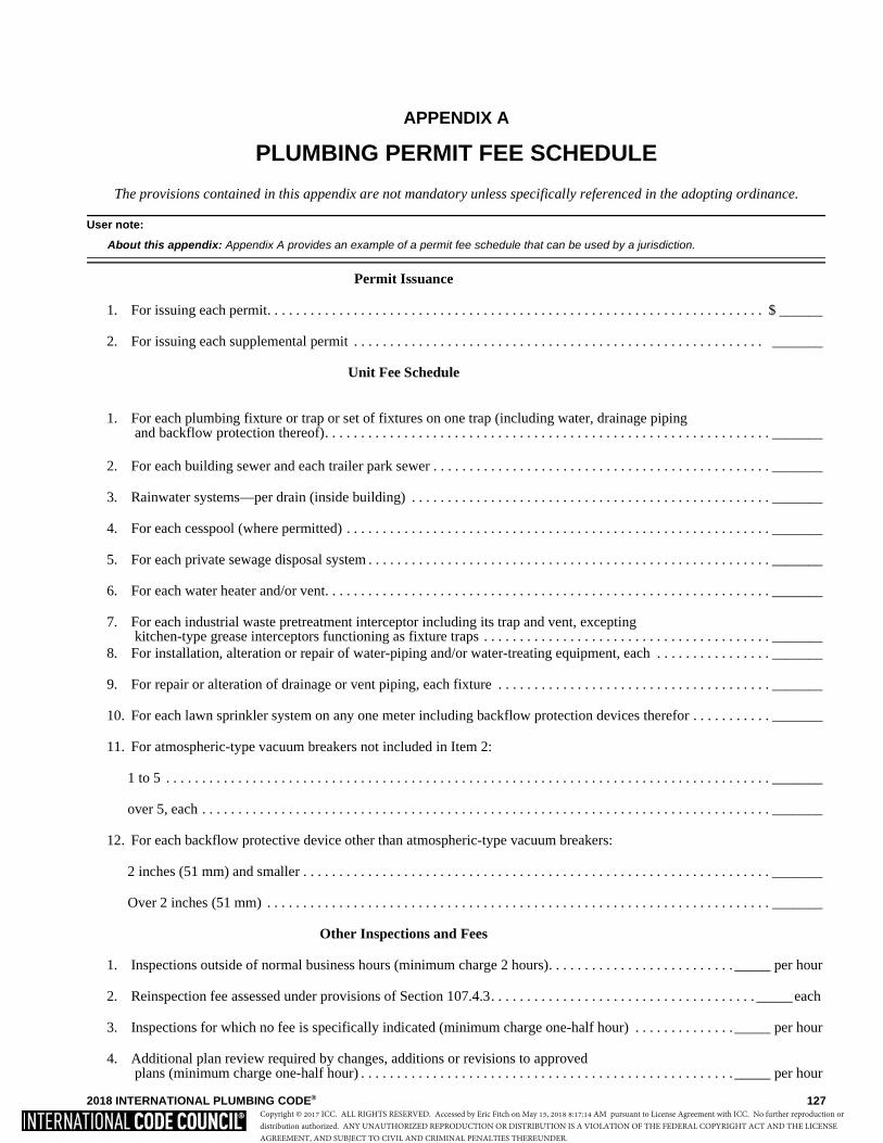
2018 INTERNATIONAL PLUMBING CODE® 127
APPENDIX A
PLUMBING PERMIT FEE SCHEDULE
The provisions contained in this appendix are not mandatory unless specifically referenced in the adopting ordinance.
User note:
About this appendix: Appendix A provides an example of a permit fee schedule that can be used by a jurisdiction.
Permit Issuance
1. For issuing each permit. . . . . . . . . . . . . . . . . . . . . . . . . . . . . . . . . . . . . . . . . . . . . . . . . . . . . . . . . . . . . . . . . . . . . $ ______
2. For issuing each supplemental permit . . . . . . . . . . . . . . . . . . . . . . . . . . . . . . . . . . . . . . . . . . . . . . . . . . . . . . . . . _______
Unit Fee Schedule
1. For each plumbing fixture or trap or set of fixtures on one trap (including water, drainage piping and backflow protection thereof). . . . . . . . . . . . . . . . . . . . . . . . . . . . . . . . . . . . . . . . . . . . . . . . . . . . . . . . . . . . . . _______
2. For each building sewer and each trailer park sewer . . . . . . . . . . . . . . . . . . . . . . . . . . . . . . . . . . . . . . . . . . . . . . . _______
3. Rainwater systems—per drain (inside building) . . . . . . . . . . . . . . . . . . . . . . . . . . . . . . . . . . . . . . . . . . . . . . . . . . _______
4. For each cesspool (where permitted) . . . . . . . . . . . . . . . . . . . . . . . . . . . . . . . . . . . . . . . . . . . . . . . . . . . . . . . . . . . _______
5. For each private sewage disposal system . . . . . . . . . . . . . . . . . . . . . . . . . . . . . . . . . . . . . . . . . . . . . . . . . . . . . . . . _______
6. For each water heater and/or vent. . . . . . . . . . . . . . . . . . . . . . . . . . . . . . . . . . . . . . . . . . . . . . . . . . . . . . . . . . . . . . _______
7. For each industrial waste pretreatment interceptor including its trap and vent, excepting kitchen-type grease interceptors functioning as fixture traps . . . . . . . . . . . . . . . . . . . . . . . . . . . . . . . . . . . . . . . . _______
8. For installation, alteration or repair of water-piping and/or water-treating equipment, each . . . . . . . . . . . . . . . . _______
9. For repair or alteration of drainage or vent piping, each fixture . . . . . . . . . . . . . . . . . . . . . . . . . . . . . . . . . . . . . . _______
10. For each lawn sprinkler system on any one meter including backflow protection devices therefor . . . . . . . . . . . _______
11. For atmospheric-type vacuum breakers not included in Item 2:
1 to 5 . . . . . . . . . . . . . . . . . . . . . . . . . . . . . . . . . . . . . . . . . . . . . . . . . . . . . . . . . . . . . . . . . . . . . . . . . . . . . . . . . . . . _______
over 5, each . . . . . . . . . . . . . . . . . . . . . . . . . . . . . . . . . . . . . . . . . . . . . . . . . . . . . . . . . . . . . . . . . . . . . . . . . . . . . . . _______
12. For each backflow protective device other than atmospheric-type vacuum breakers:
2 inches (51 mm) and smaller . . . . . . . . . . . . . . . . . . . . . . . . . . . . . . . . . . . . . . . . . . . . . . . . . . . . . . . . . . . . . . . . . _______
Over 2 inches (51 mm) . . . . . . . . . . . . . . . . . . . . . . . . . . . . . . . . . . . . . . . . . . . . . . . . . . . . . . . . . . . . . . . . . . . . . . _______
Other Inspections and Fees
1. Inspections outside of normal business hours (minimum charge 2 hours). . . . . . . . . . . . . . . . . . . . . . . . . . _____ per hour
2. Reinspection fee assessed under provisions of Section 107.4.3. . . . . . . . . . . . . . . . . . . . . . . . . . . . . . . . . . . . . _____ each
3. Inspections for which no fee is specifically indicated (minimum charge one-half hour) . . . . . . . . . . . . . . _____ per hour
4. Additional plan review required by changes, additions or revisions to approved plans (minimum charge one-half hour) . . . . . . . . . . . . . . . . . . . . . . . . . . . . . . . . . . . . . . . . . . . . . . . . . . . . _____ per hour
Copyright © 2017 ICC. ALL RIGHTS RESERVED. Accessed by Eric Fitch on May 15, 2018 8:17:14 AM pursuant to License Agreement with ICC. No further reproduction ordistribution authorized. ANY UNAUTHORIZED REPRODUCTION OR DISTRIBUTION IS A VIOLATION OF THE FEDERAL COPYRIGHT ACT AND THE LICENSEAGREEMENT, AND SUBJECT TO CIVIL AND CRIMINAL PENALTIES THEREUNDER.

128 2018 INTERNATIONAL PLUMBING CODE®
Copyright © 2017 ICC. ALL RIGHTS RESERVED. Accessed by Eric Fitch on May 15, 2018 8:17:14 AM pursuant to License Agreement with ICC. No further reproduction ordistribution authorized. ANY UNAUTHORIZED REPRODUCTION OR DISTRIBUTION IS A VIOLATION OF THE FEDERAL COPYRIGHT ACT AND THE LICENSEAGREEMENT, AND SUBJECT TO CIVIL AND CRIMINAL PENALTIES THEREUNDER.

2018 INTERNATIONAL PLUMBING CODE® 129
APPENDIX B
RATES OF RAINFALL FOR VARIOUS CITIES
This appendix is informative and is not part of the code.
User note:
About this appendix: The design of storm water drainage systems (Chapter 11) requires determination of the design rainfall event for thegeographic location of the building. Appendix B provides a list of major cities in the U.S. along with the 1-hour duration, 100-year occurrencerainfall rate.
Rainfall rates, in inches per hour, are based on a storm of 1-hour duration and a 100-year return period. The rainfall rates shownin the appendix are derived from Figure 1106.1.
Alabama: Florida: Louisville . . . . . . . . . . . . . 3.2 Springfield. . . . . . . . . . . . 3.4 Birmingham . . . . . . . . . . .3.8 Jacksonville . . . . . . . . . . . 4.3 Middlesboro . . . . . . . . . . . 3.2 St. Louis . . . . . . . . . . . . . 3.2 Huntsville . . . . . . . . . . . . .3.6 Key West . . . . . . . . . . . . . 4.3 Paducah . . . . . . . . . . . . . . 3.3 Mobile . . . . . . . . . . . . . . . .4.6 Miami . . . . . . . . . . . . . . . 4.7 Montana: Montgomery . . . . . . . . . . .4.2 Pensacola . . . . . . . . . . . . . 4.6 Louisiana: Ekalaka . . . . . . . . . . . . . . 2.5
Tampa . . . . . . . . . . . . . . . 4.5 Alexandria . . . . . . . . . . . . 4.2 Havre. . . . . . . . . . . . . . . . 1.6 Alaska: Lake Providence. . . . . . . . 4.0 Helena . . . . . . . . . . . . . . . 1.5
Fairbanks. . . . . . . . . . . . . .1.0 Georgia: New Orleans. . . . . . . . . . . 4.8 Kalispell . . . . . . . . . . . . . 1.2 Juneau . . . . . . . . . . . . . . . .0.6 Atlanta . . . . . . . . . . . . . . . 3.7 Shreveport . . . . . . . . . . . . 3.9 Missoula . . . . . . . . . . . . . 1.3
Dalton . . . . . . . . . . . . . . . 3.4 Arizona: Macon . . . . . . . . . . . . . . . 3.9 Maine: Nebraska:
Flagstaff . . . . . . . . . . . . . .2.4 Savannah . . . . . . . . . . . . . 4.3 Bangor . . . . . . . . . . . . . . . 2.2 North Platte . . . . . . . . . . . 3.3 Nogales . . . . . . . . . . . . . . .3.1 Thomasville . . . . . . . . . . . 4.3 Houlton. . . . . . . . . . . . . . . 2.1 Omaha. . . . . . . . . . . . . . . 3.8 Phoenix . . . . . . . . . . . . . . .2.5 Portland . . . . . . . . . . . . . . 2.4 Scottsbluff . . . . . . . . . . . . 3.1 Yuma. . . . . . . . . . . . . . . . .1.6 Hawaii: Valentine. . . . . . . . . . . . . 3.2
Hilo . . . . . . . . . . . . . . . . . 6.2 Maryland: Arkansas: Honolulu . . . . . . . . . . . . . 3.0 Baltimore . . . . . . . . . . . . . 3.2 Nevada:
Fort Smith . . . . . . . . . . . . .3.6 Wailuku . . . . . . . . . . . . . . 3.0 Hagerstown . . . . . . . . . . . 2.8 Elko . . . . . . . . . . . . . . . . . 1.0 Little Rock . . . . . . . . . . . .3.7 Oakland . . . . . . . . . . . . . . 2.7 Ely. . . . . . . . . . . . . . . . . . 1.1 Texarkana . . . . . . . . . . . . .3.8 Idaho: Salisbury. . . . . . . . . . . . . . 3.1 Las Vegas . . . . . . . . . . . . 1.4
Boise . . . . . . . . . . . . . . . . 0.9 Reno . . . . . . . . . . . . . . . . 1.1 California: Lewiston . . . . . . . . . . . . . 1.1 Massachusetts:
Barstow . . . . . . . . . . . . . . .1.4 Pocatello . . . . . . . . . . . . . 1.2 Boston . . . . . . . . . . . . . . . 2.5 New Hampshire: Crescent City. . . . . . . . . . .1.5 Pittsfield . . . . . . . . . . . . . . 2.8 Berlin. . . . . . . . . . . . . . . . 2.5 Fresno . . . . . . . . . . . . . . . .1.1 Illinois: Worcester . . . . . . . . . . . . . 2.7 Concord. . . . . . . . . . . . . . 2.5 Los Angeles . . . . . . . . . . .2.1 Cairo . . . . . . . . . . . . . . . . 3.3 Keene . . . . . . . . . . . . . . . 2.4 Needles . . . . . . . . . . . . . . .1.6 Chicago . . . . . . . . . . . . . . 3.0 Michigan: Placerville . . . . . . . . . . . . .1.5 Peoria. . . . . . . . . . . . . . . . 3.3 Alpena . . . . . . . . . . . . . . . 2.5 New Jersey: San Fernando . . . . . . . . . .2.3 Rockford . . . . . . . . . . . . . 3.2 Detroit . . . . . . . . . . . . . . . 2.7 Atlantic City . . . . . . . . . . 2.9 San Francisco . . . . . . . . . .1.5 Springfield . . . . . . . . . . . . 3.3 Grand Rapids . . . . . . . . . . 2.6 Newark . . . . . . . . . . . . . . 3.1 Yreka. . . . . . . . . . . . . . . . .1.4 Lansing . . . . . . . . . . . . . . . 2.8 Trenton . . . . . . . . . . . . . . 3.1
Indiana: Marquette . . . . . . . . . . . . . 2.4 Colorado: Evansville . . . . . . . . . . . . 3.2 Sault Ste. Marie . . . . . . . . 2.2 New Mexico:
Craig . . . . . . . . . . . . . . . . .1.5 Fort Wayne . . . . . . . . . . . 2.9 Albuquerque . . . . . . . . . . 2.0 Denver. . . . . . . . . . . . . . . .2.4 Indianapolis . . . . . . . . . . . 3.1 Minnesota: Hobbs . . . . . . . . . . . . . . . 3.0 Durango. . . . . . . . . . . . . . .1.8 Duluth. . . . . . . . . . . . . . . . 2.8 Raton. . . . . . . . . . . . . . . . 2.5 Grand Junction . . . . . . . . .1.7 Iowa: Grand Marais . . . . . . . . . . 2.3 Roswell . . . . . . . . . . . . . . 2.6 Lamar . . . . . . . . . . . . . . . .3.0 Davenport . . . . . . . . . . . . 3.3 Minneapolis . . . . . . . . . . . 3.1 Silver City . . . . . . . . . . . . 1.9 Pueblo . . . . . . . . . . . . . . . .2.5 Des Moines . . . . . . . . . . . 3.4 Moorhead . . . . . . . . . . . . . 3.2
Dubuque . . . . . . . . . . . . . 3.3 Worthington . . . . . . . . . . . 3.5 New York: Connecticut: Sioux City . . . . . . . . . . . . 3.6 Albany. . . . . . . . . . . . . . . 2.5
Hartford. . . . . . . . . . . . . . .2.7 Mississippi: Binghamton. . . . . . . . . . . 2.3 New Haven . . . . . . . . . . . .2.8 Kansas: Biloxi . . . . . . . . . . . . . . . . 4.7 Buffalo . . . . . . . . . . . . . . 2.3Putnam . . . . . . . . . . . . . . .2.6 Atwood . . . . . . . . . . . . . . 3.3 Columbus . . . . . . . . . . . . . 3.9 Kingston . . . . . . . . . . . . . 2.7
Dodge City. . . . . . . . . . . . 3.3 Corinth . . . . . . . . . . . . . . . 3.6 New York . . . . . . . . . . . . 3.0 Delaware: Topeka . . . . . . . . . . . . . . . 3.7 Natchez. . . . . . . . . . . . . . . 4.4 Rochester. . . . . . . . . . . . . 2.2
Georgetown. . . . . . . . . . . .3.0 Wichita . . . . . . . . . . . . . . 3.7 Vicksburg . . . . . . . . . . . . . 4.1 Wilmington . . . . . . . . . . . .3.1 North Carolina:
Kentucky: Missouri: Asheville . . . . . . . . . . . . . 4.1 District of Columbia: Ashland . . . . . . . . . . . . . . 3.0 Columbia . . . . . . . . . . . . . 3.2 Charlotte . . . . . . . . . . . . . 3.7
Washington . . . . . . . . . . . .3.2 Lexington. . . . . . . . . . . . . 3.1 Kansas City . . . . . . . . . . . 3.6 Greensboro . . . . . . . . . . . 3.4 Wilmington . . . . . . . . . . . 4.2
Copyright © 2017 ICC. ALL RIGHTS RESERVED. Accessed by Eric Fitch on May 15, 2018 8:17:14 AM pursuant to License Agreement with ICC. No further reproduction ordistribution authorized. ANY UNAUTHORIZED REPRODUCTION OR DISTRIBUTION IS A VIOLATION OF THE FEDERAL COPYRIGHT ACT AND THE LICENSEAGREEMENT, AND SUBJECT TO CIVIL AND CRIMINAL PENALTIES THEREUNDER.
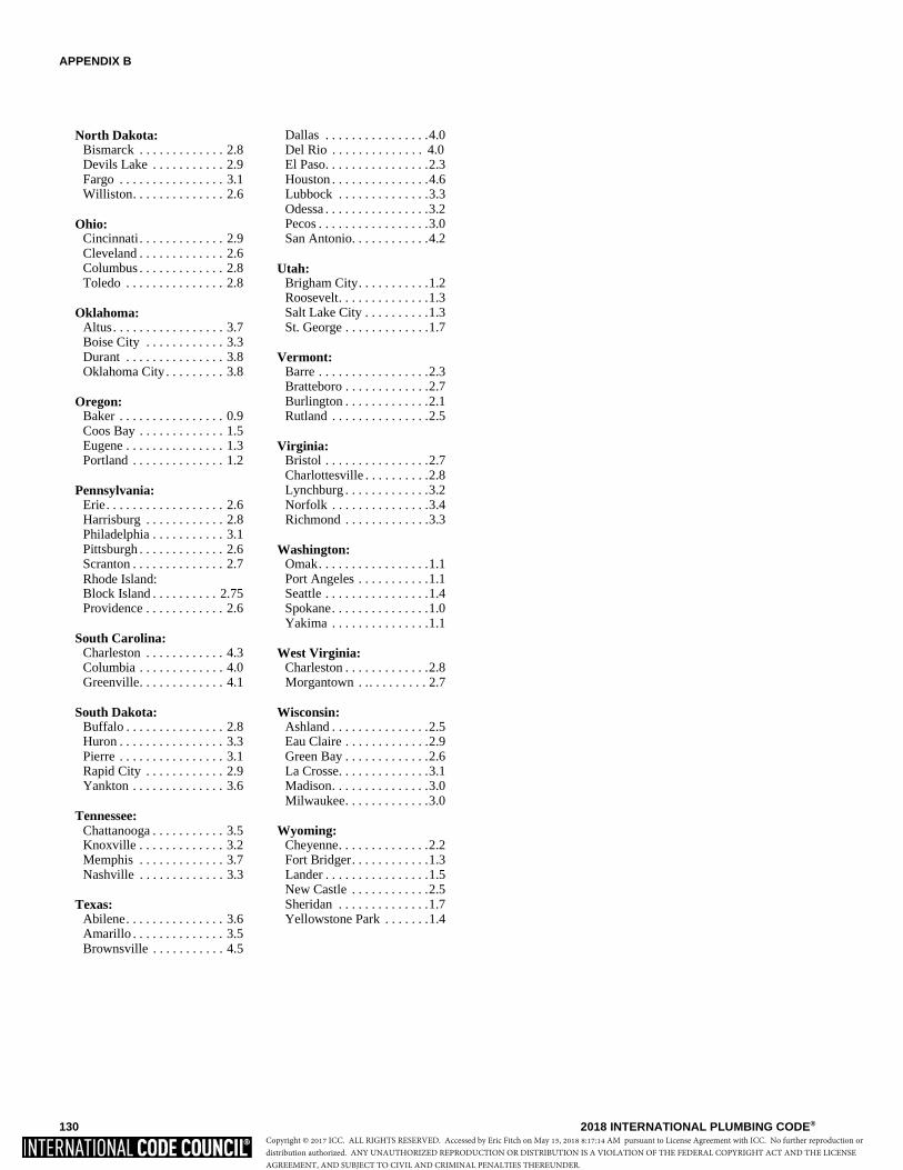
APPENDIX B
130 2018 INTERNATIONAL PLUMBING CODE®
North Dakota: Dallas . . . . . . . . . . . . . . . .4.0 Bismarck . . . . . . . . . . . . . 2.8 Del Rio . . . . . . . . . . . . . . 4.0 Devils Lake . . . . . . . . . . . 2.9 El Paso. . . . . . . . . . . . . . . .2.3 Fargo . . . . . . . . . . . . . . . . 3.1 Houston . . . . . . . . . . . . . . .4.6Williston. . . . . . . . . . . . . . 2.6 Lubbock . . . . . . . . . . . . . .3.3 Odessa . . . . . . . . . . . . . . . .3.2
Ohio: Pecos . . . . . . . . . . . . . . . . .3.0 Cincinnati. . . . . . . . . . . . . 2.9 San Antonio. . . . . . . . . . . .4.2Cleveland . . . . . . . . . . . . . 2.6 Columbus . . . . . . . . . . . . . 2.8 Utah: Toledo . . . . . . . . . . . . . . . 2.8 Brigham City. . . . . . . . . . .1.2
Roosevelt. . . . . . . . . . . . . .1.3 Oklahoma: Salt Lake City . . . . . . . . . .1.3
Altus. . . . . . . . . . . . . . . . . 3.7 St. George . . . . . . . . . . . . .1.7Boise City . . . . . . . . . . . . 3.3Durant . . . . . . . . . . . . . . . 3.8 Vermont:Oklahoma City . . . . . . . . . 3.8 Barre . . . . . . . . . . . . . . . . .2.3
Bratteboro . . . . . . . . . . . . .2.7 Oregon: Burlington . . . . . . . . . . . . .2.1
Baker . . . . . . . . . . . . . . . . 0.9 Rutland . . . . . . . . . . . . . . .2.5Coos Bay . . . . . . . . . . . . . 1.5Eugene . . . . . . . . . . . . . . . 1.3 Virginia: Portland . . . . . . . . . . . . . . 1.2 Bristol . . . . . . . . . . . . . . . .2.7
Charlottesville . . . . . . . . . .2.8 Pennsylvania: Lynchburg . . . . . . . . . . . . .3.2
Erie. . . . . . . . . . . . . . . . . . 2.6 Norfolk . . . . . . . . . . . . . . .3.4 Harrisburg . . . . . . . . . . . . 2.8 Richmond . . . . . . . . . . . . .3.3 Philadelphia . . . . . . . . . . . 3.1 Pittsburgh . . . . . . . . . . . . . 2.6 Washington: Scranton . . . . . . . . . . . . . . 2.7 Omak. . . . . . . . . . . . . . . . .1.1 Rhode Island: Port Angeles . . . . . . . . . . .1.1 Block Island . . . . . . . . . . 2.75 Seattle . . . . . . . . . . . . . . . .1.4 Providence . . . . . . . . . . . . 2.6 Spokane. . . . . . . . . . . . . . .1.0
Yakima . . . . . . . . . . . . . . .1.1 South Carolina:
Charleston . . . . . . . . . . . . 4.3 West Virginia: Columbia . . . . . . . . . . . . . 4.0 Charleston . . . . . . . . . . . . .2.8Greenville. . . . . . . . . . . . . 4.1 Morgantown . .. . . . . . . . . 2.7
South Dakota: Wisconsin:Buffalo . . . . . . . . . . . . . . . 2.8 Ashland . . . . . . . . . . . . . . .2.5Huron . . . . . . . . . . . . . . . . 3.3 Eau Claire . . . . . . . . . . . . .2.9 Pierre . . . . . . . . . . . . . . . . 3.1 Green Bay . . . . . . . . . . . . .2.6 Rapid City . . . . . . . . . . . . 2.9 La Crosse. . . . . . . . . . . . . .3.1 Yankton . . . . . . . . . . . . . . 3.6 Madison. . . . . . . . . . . . . . .3.0
Milwaukee. . . . . . . . . . . . .3.0 Tennessee:
Chattanooga . . . . . . . . . . . 3.5 Wyoming: Knoxville . . . . . . . . . . . . . 3.2 Cheyenne. . . . . . . . . . . . . .2.2 Memphis . . . . . . . . . . . . . 3.7 Fort Bridger. . . . . . . . . . . .1.3Nashville . . . . . . . . . . . . . 3.3 Lander . . . . . . . . . . . . . . . .1.5
New Castle . . . . . . . . . . . .2.5 Texas: Sheridan . . . . . . . . . . . . . .1.7
Abilene. . . . . . . . . . . . . . . 3.6 Yellowstone Park . . . . . . .1.4Amarillo . . . . . . . . . . . . . . 3.5Brownsville . . . . . . . . . . . 4.5
Copyright © 2017 ICC. ALL RIGHTS RESERVED. Accessed by Eric Fitch on May 15, 2018 8:17:14 AM pursuant to License Agreement with ICC. No further reproduction ordistribution authorized. ANY UNAUTHORIZED REPRODUCTION OR DISTRIBUTION IS A VIOLATION OF THE FEDERAL COPYRIGHT ACT AND THE LICENSEAGREEMENT, AND SUBJECT TO CIVIL AND CRIMINAL PENALTIES THEREUNDER.
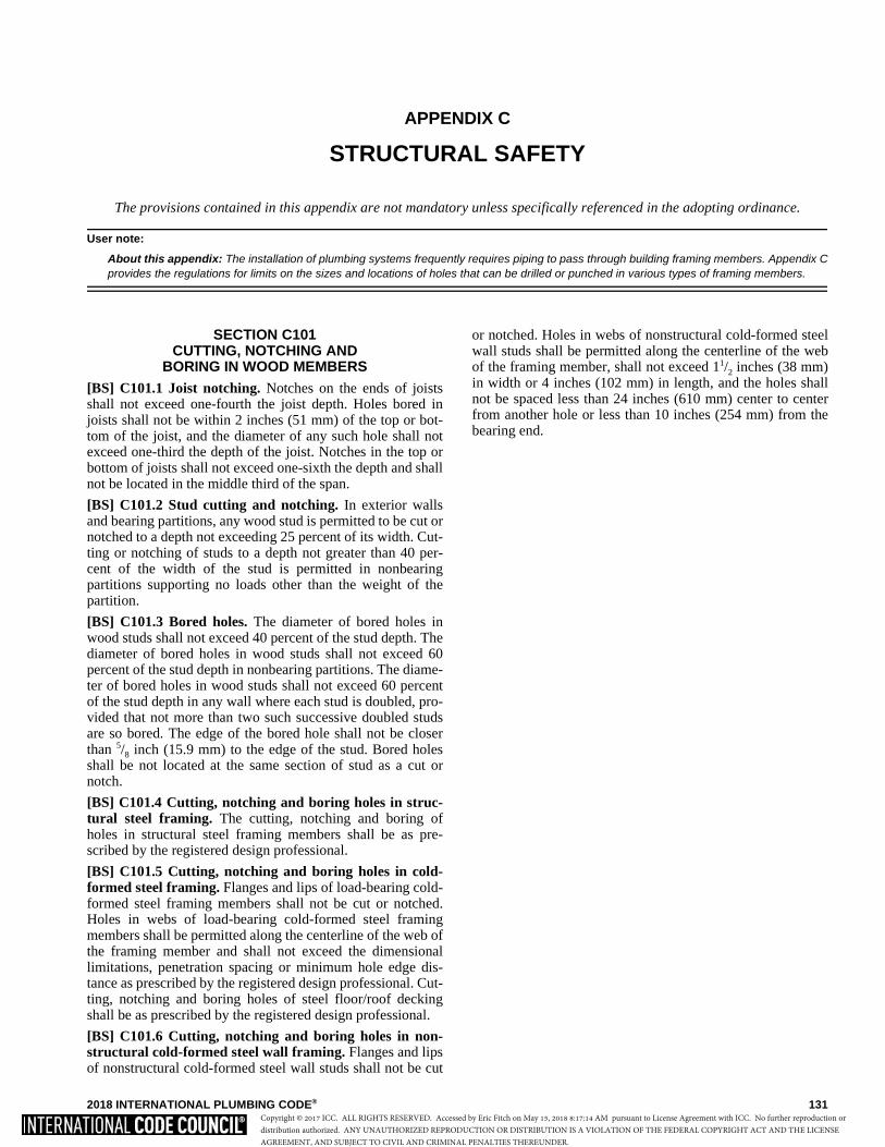
2018 INTERNATIONAL PLUMBING CODE® 131
APPENDIX C
STRUCTURAL SAFETY
The provisions contained in this appendix are not mandatory unless specifically referenced in the adopting ordinance.
User note:
About this appendix: The installation of plumbing systems frequently requires piping to pass through building framing members. Appendix Cprovides the regulations for limits on the sizes and locations of holes that can be drilled or punched in various types of framing members.
SECTION C101 CUTTING, NOTCHING AND
BORING IN WOOD MEMBERS[BS] C101.1 Joist notching. Notches on the ends of joistsshall not exceed one-fourth the joist depth. Holes bored injoists shall not be within 2 inches (51 mm) of the top or bot-tom of the joist, and the diameter of any such hole shall notexceed one-third the depth of the joist. Notches in the top orbottom of joists shall not exceed one-sixth the depth and shallnot be located in the middle third of the span.
[BS] C101.2 Stud cutting and notching. In exterior wallsand bearing partitions, any wood stud is permitted to be cut ornotched to a depth not exceeding 25 percent of its width. Cut-ting or notching of studs to a depth not greater than 40 per-cent of the width of the stud is permitted in nonbearingpartitions supporting no loads other than the weight of thepartition.
[BS] C101.3 Bored holes. The diameter of bored holes inwood studs shall not exceed 40 percent of the stud depth. Thediameter of bored holes in wood studs shall not exceed 60percent of the stud depth in nonbearing partitions. The diame-ter of bored holes in wood studs shall not exceed 60 percentof the stud depth in any wall where each stud is doubled, pro-vided that not more than two such successive doubled studsare so bored. The edge of the bored hole shall not be closerthan 5/8 inch (15.9 mm) to the edge of the stud. Bored holesshall be not located at the same section of stud as a cut ornotch.
[BS] C101.4 Cutting, notching and boring holes in struc-tural steel framing. The cutting, notching and boring ofholes in structural steel framing members shall be as pre-scribed by the registered design professional.
[BS] C101.5 Cutting, notching and boring holes in cold-formed steel framing. Flanges and lips of load-bearing cold-formed steel framing members shall not be cut or notched.Holes in webs of load-bearing cold-formed steel framingmembers shall be permitted along the centerline of the web ofthe framing member and shall not exceed the dimensionallimitations, penetration spacing or minimum hole edge dis-tance as prescribed by the registered design professional. Cut-ting, notching and boring holes of steel floor/roof deckingshall be as prescribed by the registered design professional.
[BS] C101.6 Cutting, notching and boring holes in non-structural cold-formed steel wall framing. Flanges and lipsof nonstructural cold-formed steel wall studs shall not be cut
or notched. Holes in webs of nonstructural cold-formed steelwall studs shall be permitted along the centerline of the webof the framing member, shall not exceed 11/2 inches (38 mm)in width or 4 inches (102 mm) in length, and the holes shallnot be spaced less than 24 inches (610 mm) center to centerfrom another hole or less than 10 inches (254 mm) from thebearing end.
Copyright © 2017 ICC. ALL RIGHTS RESERVED. Accessed by Eric Fitch on May 15, 2018 8:17:14 AM pursuant to License Agreement with ICC. No further reproduction ordistribution authorized. ANY UNAUTHORIZED REPRODUCTION OR DISTRIBUTION IS A VIOLATION OF THE FEDERAL COPYRIGHT ACT AND THE LICENSEAGREEMENT, AND SUBJECT TO CIVIL AND CRIMINAL PENALTIES THEREUNDER.

132 2018 INTERNATIONAL PLUMBING CODE®
Copyright © 2017 ICC. ALL RIGHTS RESERVED. Accessed by Eric Fitch on May 15, 2018 8:17:14 AM pursuant to License Agreement with ICC. No further reproduction ordistribution authorized. ANY UNAUTHORIZED REPRODUCTION OR DISTRIBUTION IS A VIOLATION OF THE FEDERAL COPYRIGHT ACT AND THE LICENSEAGREEMENT, AND SUBJECT TO CIVIL AND CRIMINAL PENALTIES THEREUNDER.

2018 INTERNATIONAL PLUMBING CODE® 133
APPENDIX D
DEGREE DAY AND DESIGN TEMPERATURES
This appendix is informative and is not part of the code.
User note:
About this appendix: This code refers to the 97.5 percent winter design temperature for directing the code user to requirements for design ofthe plumbing system. Appendix D provides such temperatures for many major cities in the United States.
TABLE D101 DEGREE DAY AND DESIGN TEMPERATURESa FOR CITIES IN THE UNITED STATES
(continued)
STATE STATIONb
HEATING DEGREE DAYS
(yearly total)
DESIGN TEMPERATURES
DEGREES NORTH LATITUDEc
Winter Summer
971/2% Dry bulb 21/2% Wet bulb 21/2%
AL
Birmingham Huntsville Mobile Montgomery
2,551
3,070
1,560
2,291
21
16
29
25
94
96
93
95
77
77
79
79
33°30′
34°40′
30°40′
32°20′
AK
Anchorage Fairbanks Juneau Nome
10,864
14,279
9,075
14,171
-18
-47 1
-27
68
78
70
62
59
62
59
56
61°10′
64°50′
58°20′
64°30′
AZ
Flagstaff Phoenix Tuscon Yuma
7,152
1,765
1,800
974
4
34
32
39
82
107
102
109
60
75
71
78
35°10′
33°30′
33°10′
32°40′
AR Fort Smith Little Rock Texarkana
3,292
3,219
2,533
17
20
23
98
96
96
79
79
79
35°20′
34°40′
33°30′
CA
Fresno Long Beach Los Angeles Los Angelesd
Oakland Sacramento San Diego San Francisco San Franciscod
2,611
1,803
2,061
1,349
2,870
2,502
1,458
3,015
3,001
30
43
43
40
36
32
44
38
40
100
80
80
89
80
98
80
77
71
71
69
69
71
64
71
70
64
62
36°50′
33°50′
34°00′
34°00′
37°40′
38°30′
32°40′
37°40′
37°50′
CO
Alamosa Colorado Springs Denver Grand Junction Pueblo
8,529
6,423
6,283
5,641
5,462
-16 2 1 7 0
82
88
91
94
95
61
62
63
63
66
37°30′
38°50′
39°50′
39°10′
38°20′
CT Bridgeport Hartford New Haven
5,617
6,235
5,897
9 7 7
84
88
84
74
75
75
41°10′
41°50′
41°20′DE Wilmington 4,930 14 89 76 39°40′DC Washington 4,224 17 91 77 38°50′
Copyright © 2017 ICC. ALL RIGHTS RESERVED. Accessed by Eric Fitch on May 15, 2018 8:17:14 AM pursuant to License Agreement with ICC. No further reproduction ordistribution authorized. ANY UNAUTHORIZED REPRODUCTION OR DISTRIBUTION IS A VIOLATION OF THE FEDERAL COPYRIGHT ACT AND THE LICENSEAGREEMENT, AND SUBJECT TO CIVIL AND CRIMINAL PENALTIES THEREUNDER.

APPENDIX D
134 2018 INTERNATIONAL PLUMBING CODE®
TABLE D101—continuedDEGREE DAY AND DESIGN TEMPERATURESa FOR CITIES IN THE UNITED STATES
(continued)
STATE STATIONb
HEATING DEGREE DAYS (yearly total)
DESIGN TEMPERATURES
DEGREES NORTH LATITUDEc
Winter Summer
971/2% Dry bulb 21/2% Wet bulb 21/2%
FL
Daytona Fort Myers Jacksonville Key West Miami Orlando Pensacola Tallahassee Tampa West Palm Beach
879
442
1,239
108
214
766
1,463
1,485
683
253
35
44
32
57
47
38
29
30
40
45
90
92
94
90
90
93
93
92
91
91
79
79
79
79
79
78
79
78
79
79
29°10′
26°40′
30°30′
24°30′
25°50′
28°30′
30°30′
30°20′
28°00′
26°40′
GA
Athens Atlanta Augusta Columbus Macon Rome Savannah
2,929
2,961
2,397
2,383
2,136
3,326
1,819
22
22
23
24
25
22
27
92
92
95
93
93
93
93
77
76
79
78
78
78
79
34°00′
33°40′
33°20′
32°30′
32°40′
34°20′
32°10′
HI Hilo Honolulu
0 0
62
6383
8674
7519°40′
21°20′
ID Boise Lewiston Pocatello
5,809
5,542
7,033
10 6
-1
94
93
91
66
66
63
43°30′
46°20′
43°00′
IL
Chicago (Midway) Chicago (O'Hare) Chicagod
Moline Peoria Rockford Springfield
6,155
6,639
5,882
6,408
6,025
6,830
5,429
0
-4 2
-4
-4
-4 2
91
89
91
91
89
89
92
75
76
77
77
76
76
77
41°50′
42°00′
41°50′
41°30′
40°40′
42°10′
39°50′
IN
Evansville Fort Wayne Indianapolis South Bend
4,435
6,205
5,699
6,439
9 1 2 1
93
89
90
89
78
75
76
75
38°00′
41°00′
39°40′
41°40′
IA
Burlington Des Moines Dubuque Sioux City Waterloo
6,114
6,588
7,376
6,951
7,320
-3
-5
-7
-7
-10
91
91
88
92
89
77
77
75
77
77
40°50′
41°30′
42°20′
42°20′
42°30′
KS
Dodge City Goodland Topeka Wichita
4,986
6,141
5,182
4,620
5 0 4 7
97
96
96
98
73
70
78
76
37°50′
39°20′
39°00′
37°40′
KY Covington Lexington Louisville
5,265
4,683
4,660
6 8
10
90
91
93
75
76
77
39°00′
38°00′
38°10′
LA
Alexandria Baton Rouge Lake Charles New Orleans Shreveport
1,921
1,560
1,459
1,385
2,184
27
29
31
33
25
94
93
93
92
96
79
80
79
80
79
31°20′
30°30′
30°10′
30°00′
32°30′
Copyright © 2017 ICC. ALL RIGHTS RESERVED. Accessed by Eric Fitch on May 15, 2018 8:17:14 AM pursuant to License Agreement with ICC. No further reproduction ordistribution authorized. ANY UNAUTHORIZED REPRODUCTION OR DISTRIBUTION IS A VIOLATION OF THE FEDERAL COPYRIGHT ACT AND THE LICENSEAGREEMENT, AND SUBJECT TO CIVIL AND CRIMINAL PENALTIES THEREUNDER.
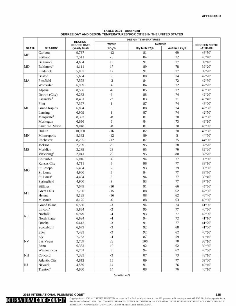
APPENDIX D
2018 INTERNATIONAL PLUMBING CODE® 135
TABLE D101—continuedDEGREE DAY AND DESIGN TEMPERATURESa FOR CITIES IN THE UNITED STATES
(continued)
STATE STATIONb
HEATING DEGREE DAYS
(yearly total)
DESIGN TEMPERATURES
DEGREES NORTH LATITUDEc
Winter Summer
971/2% Dry bulb 21/2% Wet bulb 21/2%
ME Caribou Portland
9,767
7,511-13
-1
81
8469
7246°50′
43°40′
MD Baltimore Baltimored
Frederick
4,654
4,111
5,087
13
17
12
91
89
91
77
78
77
39°10′
39°20′
39°20′
MA Boston Pittsfield Worcester
5,634
7,578
6,969
9
-3 4
88
84
84
74
72
72
42°20′
42°30′
42°20′
MI
Alpena Detroit (City) Escanabad
Flint Grand Rapids Lansing Marquetted
Muskegon Sault Ste. Marie
8,506
6,232
8,481
7,377
6,894
6,909
8,393
6,696
9,048
-6 6
-7 1 5 1
-8 6
-8
85
88
83
87
88
87
81
84
81
72
74
71
74
74
74
70
73
70
45°00′
42°20′
45°40′
43°00′
42°50′
42°50′
46°30′
43°10′
46°30′
MN Duluth Minneapolis Rochester
10,000
8,382
8,295
-16
-12
-12
82
89
87
70 5
75
46°50′
44°50′
44°00′
MS Jackson Meridian Vicksburgd
2,239
2,289
2,041
25
23
26
95
95
95
78
79
80
32°20′
32°20′
32°20′
MO
Columbia Kansas City St. Joseph St. Louis St. Louisd
Springfield
5,046
4,711
5,484
4,900
4,484
4,900
4 6 2 6 8 9
94
96
93
94
94
93
77
77
79
77
77
77
39°00′
39°10′
39°50′
38°50′
38°40′
37°10′
MT
Billings Great Falls Helena Missoula
7,049
7,750
8,129
8,125
-10
-15
-16
-6
91
88
88
88
66
62
62
63
45°50′
47°30′
46°40′
46°50′
NE
Grand Island Lincolnd
Norfolk North Platte Omaha Scottsbluff
6,530
5,864
6,979
6,684
6,612
6,673
-3
-2
-4
-4
-3
-3
94
95
93
94
91
92
74
77
77
72
77
68
41°00′
40°50′
42°00′
41°10′
41°20′
41°50′
NV
Elko Ely Las Vegas Reno Winnemucca
7,433
7,733
2,709
6,332
6,761
-2
-4
28
10 3
92
87
106
92
94
62
59
70
62
62
40°50′
39°10′
36°10′
39°30′
40°50′NH Concord 7,383 -3 87 73 43°10′
NJ Atlantic City Newark Trentond
4,812
4,589
4,980
13
14
14
89
91
88
77
76
76
39°30′
40°40′
40°10′
Copyright © 2017 ICC. ALL RIGHTS RESERVED. Accessed by Eric Fitch on May 15, 2018 8:17:14 AM pursuant to License Agreement with ICC. No further reproduction ordistribution authorized. ANY UNAUTHORIZED REPRODUCTION OR DISTRIBUTION IS A VIOLATION OF THE FEDERAL COPYRIGHT ACT AND THE LICENSEAGREEMENT, AND SUBJECT TO CIVIL AND CRIMINAL PENALTIES THEREUNDER.

APPENDIX D
136 2018 INTERNATIONAL PLUMBING CODE®
TABLE D101—continuedDEGREE DAY AND DESIGN TEMPERATURESa FOR CITIES IN THE UNITED STATES
(continued)
STATE STATIONb
HEATING DEGREE DAYS
(yearly total)
DESIGN TEMPERATURES
DEGREES NORTH LATITUDEc
Winter Summer
971/2% Dry bulb 21/2% Wet bulb 21/2%
NY
Albany Albanyd
Binghamton Buffalo NY (Central Park)d
NY (Kennedy) NY(LaGuardia) Rochester Schenectadyd
Syracuse
6,875
6,201
7,286
7,062
4,871
5,219
4,811
6,748
6,650
6,756
-1 1 1 6
15
15
15 5 1 2
88
88
83
85
89
87
89
88
87
87
74
74
72
73
75
75
75
73
74
73
42°50′
42°50′
42°10′
43°00′
40°50′
40°40′
40°50′
43°10′
42°50′
43°10′
NC
Charlotte Greensboro Raleigh Winston-Salem
3,181
3,805
3,393
3,595
22
18
20
20
93
91
92
91
76
76
77
75
35°10′
36°10′
35°50′
36°10′
ND
Bismarck Devils Laked
Fargo Williston
8,851
9,901
9,226
9,243
-19
-21
-18
-21
91
88
89
88
71
71
74
70
46°50′
48°10′
46°50′
48°10′
OH
Akron-Canton Cincinnatid
Cleveland Columbus Dayton Mansfield Sanduskyd
Toledo Youngstown
6,037
4,410
6,351
5,660
5,622
6,403
5,796
6,494
6,417
6 6 5 5 4 5 6 1 4
86
90
88
90
89
87
91
88
86
73
75
74
75
75
74
74
75
73
41°00′
39°10′
41°20′
40°00′
39°50′
40°50′
41°30′
41°40′
41°20′
OK Oklahoma City Tulsa
3,725
3,86013
1397
9877
7835°20′
36°10′
OR
Eugene Medford Portland Portlandd
Salem
4,726
5,008
4,635
4,109
4,754
22
23
23
24
23
89
94
85
86
88
67
68
67
67
68
44°10′
42°20′
45°40′
45°30′
45°00′
PA
Allentown Erie Harrisburg Philadelphia Pittsburgh Pittsburghd
Readingd
Scranton Williamsport
5,810
6,451
5,251
5,144
5,987
5,053
4,945
6,254
5,934
9 9
11
14 5 7
13 5 7
88
85
91
90
86
88
89
87
89
75
74
76
76
73
73
75
73
74
40°40′
42°10′
40°10′
39°50′
40°30′
40°30′
40°20′
41°20′
41°10′RI Providence 5,954 9 86 74 41°40′
SC Charleston Charlestond
Columbia
2,033
1,794
2,484
27
28
24
91
92
95
80
80
78
32°50′
32°50′
34°00′
Copyright © 2017 ICC. ALL RIGHTS RESERVED. Accessed by Eric Fitch on May 15, 2018 8:17:14 AM pursuant to License Agreement with ICC. No further reproduction ordistribution authorized. ANY UNAUTHORIZED REPRODUCTION OR DISTRIBUTION IS A VIOLATION OF THE FEDERAL COPYRIGHT ACT AND THE LICENSEAGREEMENT, AND SUBJECT TO CIVIL AND CRIMINAL PENALTIES THEREUNDER.
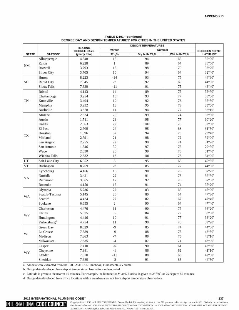
APPENDIX D
2018 INTERNATIONAL PLUMBING CODE® 137
TABLE D101—continuedDEGREE DAY AND DESIGN TEMPERATURESa FOR CITIES IN THE UNITED STATES
a. All data were extracted from the 1985 ASHRAE Handbook, Fundamentals Volume.b. Design data developed from airport temperature observations unless noted.
c. Latitude is given to the nearest 10 minutes. For example, the latitude for Miami, Florida, is given as 25°50′, or 25 degrees 50 minutes.
d. Design data developed from office locations within an urban area, not from airport temperature observations.
STATE STATIONb
HEATING DEGREE DAYS
(yearly total)
DESIGN TEMPERATURES
DEGREES NORTH LATITUDEc
Winter Summer
971/2% Dry bulb 21/2% Wet bulb 21/2%
NM
Albuquerque Raton Roswell Silver City
4,348
6,228
3,793
3,705
16 1
18
10
94
89
98
94
65
64
70
64
35°00′
36°50′
33°20′
32°40′
SD Huron Rapid City Sioux Falls
8,223
7,345
7,839
-14
-7
-11
93
92
91
75
69
75
44°30′
44°00′
43°40′
TN
Bristol Chattanooga Knoxville Memphis Nashville
4,143
3,254
3,494
3,232
3,578
14
18
19
18
14
89
93
92
95
94
75
77
76
79
77
36°30′
35°00′
35°50′
35°00′
36°10′
TX
Abilene Austin Dallas El Paso Houston Midland San Angelo San Antonio Waco Wichita Falls
2,624
1,711
2,363
2,700
1,396
2,591
2,255
1,546
2,030
2,832
20
28
22
24
32
21
22
30
26
18
99
98
100
98
94
98
99
97
99
101
74
77
78
68
79
72
74
76
78
76
32°30′
30°20′
32°50′
31°50′
29°40′
32°00′
31°20′
29°30′
31°40′
34°00′UT Salt Lake City 6,052 8 95 65 40°50′VT Burlington 8,269 -7 85 72 44°30′
VA
Lynchburg Norfolk Richmond Roanoke
4,166
3,421
3,865
4,150
16
22
17
16
90
91
92
91
76
78
78
74
37°20′
36°50′
37°30′
37°20′
WA
Olympia Seattle-Tacoma Seattled
Spokane
5,236
5,145
4,424
6,655
22
26
27 2
83
80
82
90
66
64
67
64
47°00′
47°30′
47°40′
47°40′
WV
Charleston Elkins Huntington Parkersburgd
4,476
5,675
4,446
4,754
11 6
10
11
90
84
91
90
75
72
77
76
38°20′
38°50′
38°20′
39°20′
WI
Green Bay La Crosse Madison Milwaukee
8,029
7,589
7,863
7,635
-9
-9
-7
-4
85
88
88
87
74
75
75
74
44°30′
43°50′
43°10′
43°00′
WY
Casper Cheyenne Lander Sheridan
7,410
7,381
7,870
7,680
-5
-1
-11
-8
90
86
88
91
61
62
63
65
42°50′
41°10′
42°50′
44°50′
Copyright © 2017 ICC. ALL RIGHTS RESERVED. Accessed by Eric Fitch on May 15, 2018 8:17:14 AM pursuant to License Agreement with ICC. No further reproduction ordistribution authorized. ANY UNAUTHORIZED REPRODUCTION OR DISTRIBUTION IS A VIOLATION OF THE FEDERAL COPYRIGHT ACT AND THE LICENSEAGREEMENT, AND SUBJECT TO CIVIL AND CRIMINAL PENALTIES THEREUNDER.

138 2018 INTERNATIONAL PLUMBING CODE®
Copyright © 2017 ICC. ALL RIGHTS RESERVED. Accessed by Eric Fitch on May 15, 2018 8:17:14 AM pursuant to License Agreement with ICC. No further reproduction ordistribution authorized. ANY UNAUTHORIZED REPRODUCTION OR DISTRIBUTION IS A VIOLATION OF THE FEDERAL COPYRIGHT ACT AND THE LICENSEAGREEMENT, AND SUBJECT TO CIVIL AND CRIMINAL PENALTIES THEREUNDER.
2018 INTERNATIONAL PLUMBING CODE® 139
APPENDIX E
SIZING OF WATER PIPING SYSTEM
The provisions contained in this appendix are not mandatory unless specifically referenced in the adopting ordinance.
User note:
About this appendix: The sizing of water service and water distribution piping is not specified in Chapter 6 as it is left up to the designer ofthe system with the code official approving the design method. Appendix E provides several methods that could be used by a systemdesigner.
SECTION E101GENERAL
E101.1 Scope.E101.1.1 This appendix outlines two procedures for sizinga water piping system (see Sections E103.3 and E201.1).The design procedures are based on the minimum staticpressure available from the supply source, the headchanges in the system caused by friction and elevation,and the rates of flow necessary for operation of variousfixtures.E101.1.2 Because of the variable conditions encounteredin hydraulic design, it is impractical to specify definite anddetailed rules for sizing of the water piping system.Accordingly, other sizing or design methods conformingto good engineering practice standards are acceptablealternatives to those presented herein.
SECTION E102INFORMATION REQUIRED
E102.1 Preliminary. Obtain the necessary informationregarding the minimum daily static service pressure in thearea where the building is to be located. If the building supplyis to be metered, obtain information regarding friction lossrelative to the rate of flow for meters in the range of sizeslikely to be used. Friction loss data can be obtained from mostmanufacturers of water meters.E102.2 Demand load.
E102.2.1 Estimate the supply demand of the building mainand the principal branches and risers of the system bytotaling the corresponding demand from the applicablepart of Table E103.3(3).E102.2.2 Estimate continuous supply demands in gallonsper minute (L/m) for items such as lawn sprinklers and airconditioners, and add the sum to the total demand forfixtures. The result is the estimated supply demand for thebuilding supply.
SECTION E103SELECTION OF PIPE SIZE
E103.1 General. Decide from Table 604.3 what is the desir-able minimum residual pressure that should be maintained atthe highest fixture in the supply system. If the highest groupof fixtures contains flushometer valves, the pressure for thegroup should be not less than 15 pounds per square inch (psi)
(103.4 kPa) flowing. For flush tank supplies, the availablepressure should be not less than 8 psi (55.2 kPa) flowing,except blowout action fixtures must be not less than 25 psi(172.4 kPa) flowing.
E103.2 Pipe sizing.E103.2.1 Pipe sizes can be selected according to the fol-lowing procedure or by other design methods conformingto acceptable engineering practice and approved by theadministrative authority. The sizes selected must not beless than the minimum required by this code.
E103.2.2 Water pipe sizing procedures are based on a sys-tem of pressure requirements and losses, the sum of whichmust not exceed the minimum pressure available at thesupply source. These pressures are as follows:
1. Pressure required at fixture to produce requiredflow. See Sections 604.3 and 604.5.
2. Static pressure loss or gain (due to head) is com-puted at 0.433 psi per foot (9.8 kPa/m) of elevationchange.
Example: Assume that the highest fixture supplyoutlet is 20 feet (6096 mm) above or below thesupply source. This produces a static pressuredifferential of 20 feet by 0.433 psi/foot (2096 mmby 9.8 kPa/m) and an 8.66 psi (59.8 kPa) loss.
3. Loss through water meter. The friction or pressureloss can be obtained from meter manufacturers.
4. Loss through taps in water main.
5. Losses through special devices such as filters, soft-eners, backflow prevention devices and pressureregulators. These values must be obtained from themanufacturers.
6. Loss through valves and fittings. Losses for theseitems are calculated by converting to equivalentlength of piping and adding to the total pipe length.
7. Loss due to pipe friction can be calculated where thepipe size, the pipe length and the flow through thepipe are known. With these three items, the frictionloss can be determined. For piping flow charts notincluded, use manufacturers’ tables and velocity rec-ommendations.
Note: For the purposes of all examples, the fol-lowing metric conversions are applicable:
1 cubic foot per minute = 0.4719 L/s
Copyright © 2017 ICC. ALL RIGHTS RESERVED. Accessed by Eric Fitch on May 15, 2018 8:17:14 AM pursuant to License Agreement with ICC. No further reproduction ordistribution authorized. ANY UNAUTHORIZED REPRODUCTION OR DISTRIBUTION IS A VIOLATION OF THE FEDERAL COPYRIGHT ACT AND THE LICENSEAGREEMENT, AND SUBJECT TO CIVIL AND CRIMINAL PENALTIES THEREUNDER.
APPENDIX E
140 2018 INTERNATIONAL PLUMBING CODE®
1 square foot = 0.0929 m2
1 degree = 0.0175 rad
1 pound per square inch = 6.895 kPa
1 inch = 25.4 mm
1 foot = 304.8 mm
1 gallon per minute = 3.785 L/m
E103.3 Segmented loss method. The size of water servicemains, branch mains and risers by the segmented loss methodmust be determined according to water supply demand [gpm(L/m)], available water pressure [psi (kPa)] and friction losscaused by the water meter and developed length of pipe [feet(m)], including equivalent length of fittings. This design pro-cedure is based on the following parameters:
• Calculates the friction loss through each length of thepipe.
• Based on a system of pressure losses, the sum of whichmust not exceed the minimum pressure available at thestreet main or other source of supply.
• Pipe sizing based on estimated peak demand, totalpressure losses caused by difference in elevation,equipment, developed length and pressure required atmost remote fixture, loss through taps in water main,losses through fittings, filters, backflow preventiondevices, valves and pipe friction.
Because of the variable conditions encountered in hydrau-lic design, it is impractical to specify definite and detailedrules for sizing of the water piping system. Current sizingmethods do not address the differences in the probability ofuse and flow characteristics of fixtures between types ofoccupancies. Creating an exact model of predicting thedemand for a building is impossible and final studies assess-ing the impact of water conservation on demand are not yetcomplete. The following steps are necessary for the seg-mented loss method.
1. Preliminary. Obtain the necessary information regard-ing the minimum daily static service pressure in thearea where the building is to be located. If the buildingsupply is to be metered, obtain information regardingfriction loss relative to the rate of flow for meters in therange of sizes to be used. Friction loss data can beobtained from manufacturers of water meters. It isessential that enough pressure be available to overcomeall system losses caused by friction and elevation sothat plumbing fixtures operate properly. Section 604.6requires the water distribution system to be designedfor the minimum pressure available taking into consid-eration pressure fluctuations. The lowest pressure mustbe selected to guarantee a continuous, adequate supplyof water. The lowest pressure in the public main usu-ally occurs in the summer because of lawn sprinklingand supplying water for air-conditioning cooling tow-ers. Future demands placed on the public main as aresult of large growth or expansion should be consid-ered. The available pressure will decrease as additionalloads are placed on the public system.
2. Demand load. Estimate the supply demand of thebuilding main and the principal branches and risers of
the system by totaling the corresponding demand fromthe applicable part of Table E103.3(3). When estimat-ing peak demand sizing methods typically use watersupply fixture units (w.s.f.u.) [see Table E103.3(2)].This numerical factor measures the load-producingeffect of a single plumbing fixture of a given kind. Theuse of such fixture units can be applied to a single basicprobability curve (or table), found in the various sizingmethods [Table E103.3(3)]. The fixture units are thenconverted into gallons per minute (L/m) flow rate forestimating demand.
2.1. Estimate continuous supply demand in gallonsper minute (L/m) for items such as lawn sprin-klers and air conditioners, and add the sum tothe total demand for fixtures. The result is theestimated supply demand for the building sup-ply. Fixture units cannot be applied to constantuse fixtures such as hose bibbs, lawn sprinklersand air conditioners. These types of fixturesmust be assigned the gallon per minute (L/m)value.
3. Selection of pipe size. This water pipe sizing procedureis based on a system of pressure requirements andlosses, the sum of which must not exceed the minimumpressure available at the supply source. These pressuresare as follows:
3.1. Pressure required at the fixture to producerequired flow. See Sections 604.3 and 604.5.
3.2. Static pressure loss or gain (because of head) iscomputed at 0.433 psi per foot (9.8 kPa/m) ofelevation change.
3.3. Loss through a water meter. The friction orpressure loss can be obtained from the manufac-turer.
3.4. Loss through taps in water main [see TableE103.3(4)].
3.5. Losses through special devices such as filters,softeners, backflow prevention devices andpressure regulators. These values must beobtained from the manufacturers.
3.6. Loss through valves and fittings [see TablesE103.3(5) and E103.3(6)]. Losses for theseitems are calculated by converting to equivalentlength of piping and adding to the total pipelength.
3.7. Loss caused by pipe friction can be calculatedwhere the pipe size, the pipe length and the flowthrough the pipe are known. With these threeitems, the friction loss can be determined usingFigures E103.3(2) through E103.3(7). Whenusing charts, use pipe inside diameters. For pip-ing flow charts not included, use manufacturers’tables and velocity recommendations. Beforeattempting to size any water supply system, it isnecessary to gather preliminary information thatincludes available pressure, piping material,select design velocity, elevation differences and
Copyright © 2017 ICC. ALL RIGHTS RESERVED. Accessed by Eric Fitch on May 15, 2018 8:17:14 AM pursuant to License Agreement with ICC. No further reproduction ordistribution authorized. ANY UNAUTHORIZED REPRODUCTION OR DISTRIBUTION IS A VIOLATION OF THE FEDERAL COPYRIGHT ACT AND THE LICENSEAGREEMENT, AND SUBJECT TO CIVIL AND CRIMINAL PENALTIES THEREUNDER.
APPENDIX E
2018 INTERNATIONAL PLUMBING CODE® 141
developed length to most remote fixture. Thewater supply system is divided into sections atmajor changes in elevation or where brancheslead to fixture groups. The peak demand mustbe determined in each part of the hot and coldwater supply system that includes the corre-sponding water supply fixture unit and conver-sion to gallons per minute (L/m) flow rate to beexpected through each section. Sizing methodsrequire the determination of the “most hydrauli-cally remote” fixture to compute the pressureloss caused by pipe and fittings. The hydrauli-cally remote fixture represents the most down-stream fixture along the circuit of pipingrequiring the most available pressure to operateproperly. Consideration must be given to allpressure demands and losses, such as frictioncaused by pipe, fittings and equipment, eleva-tion and the residual pressure required by Table604.3. The two most common and frequentcomplaints about the water supply system oper-ation are lack of adequate pressure and noise.
Problem: What size Type L copper water pipe, service anddistribution will be required to serve a two-story factorybuilding having on each floor, back-to-back, two toilet roomseach equipped with hot and cold water? The highest fixture is21 feet (6401 mm) above the street main, which is tappedwith a 2-inch (51 mm) corporation cock at which point theminimum pressure is 55 psi (379.2 kPa). In the building base-ment, a 2-inch (51 mm) meter with a maximum pressure dropof 11 psi (75.8 kPa) and 3-inch (76 mm) reduced pressureprinciple backflow preventer with a maximum pressure dropof 9 psi (621 kPa) are to be installed. The system is shown byFigure E103.3(1). To be determined are the pipe sizes for theservice main and the cold and hot water distribution pipes.
Solution: A tabular arrangement such as shown in TableE103.3(1) should first be constructed. The steps to be fol-lowed are indicated by the tabular arrangement itself asthey are in sequence, Columns 1 through 10 and Lines Athrough L.
Step 1
Columns 1 and 2: Divide the system into sections break-ing at major changes in elevation or where branches leadto fixture groups. After point B [see Figure E103.3(1)],separate consideration will be given to the hot and coldwater piping. Enter the sections to be considered in theservice and cold water piping in Column 1 of the tabulararrangement. Column 1 of Table E103.3(1) provides aline-by-line recommended tabular arrangement for use insolving pipe sizing.
The objective in designing the water supply system isto ensure an adequate water supply and pressure to all fix-tures and equipment. Column 2 provides the pounds persquare inch (psi) to be considered separately from the min-imum pressure available at the main. Losses to take intoconsideration are the following: the differences in eleva-tion between the water supply source and the highest watersupply outlet, meter pressure losses, the tap in main loss,
special fixture devices such as water softeners and back-flow prevention devices and the pressure required at themost remote fixture outlet. The difference in elevation canresult in an increase or decrease in available pressure at themain. Where the water supply outlet is located above thesource, this results in a loss in the available pressure and issubtracted from the pressure at the water source. Wherethe highest water supply outlet is located below the watersupply source, there will be an increase in pressure that isadded to the available pressure of the water source.
Column 3: According to Table E103.3(3), determine thegpm (L/m) of flow to be expected in each section of thesystem. These flows range from 28.6 to 108 gpm. Loadvalues for fixtures must be determined as water supply fix-ture units and then converted to a gallon-per-minute (gpm)rating to determine peak demand. When calculating peakdemands, the water supply fixture units are added and thenconverted to the gallon-per-minute rating. For continuousflow fixtures such as hose bibbs and lawn sprinkler sys-tems, add the gallon-per-minute demand to the intermit-tent demand of fixtures. For example, a total of 120 watersupply fixture units is converted to a demand of 48 gallonsper minute. Two hose bibbs × 5 gpm demand = 10 gpm.Total gpm rating = 48.0 gpm + 10 gpm = 58.0 gpmdemand.
Step 2
Line A: Enter the minimum pressure available at the mainsource of supply in Column 2. This is 55 psi (379.2 kPa).The local water authorities generally keep records of pres-sures at different times of day and year. The availablepressure can be checked from nearby buildings or fromfire department hydrant checks.
Line B: Determine from Table 604.3 the highest pressurerequired for the fixtures on the system, which is 15 psi(103.4 kPa), to operate a flushometer valve. The mostremote fixture outlet is necessary to compute the pressureloss caused by pipe and fittings, and represents the mostdownstream fixture along the circuit of piping requiringthe available pressure to operate properly as indicated byTable 604.3.
Line C: Determine the pressure loss for the meter sizegiven or assumed. The total water flow from the mainthrough the service as determined in Step 1 will serve toaid in the meter selected. There are three common types ofwater meters; the pressure losses are determined by theAmerican Water Works Association Standards for dis-placement type, compound type and turbine type. Themaximum pressure loss of such devices takes into consid-eration the meter size, safe operating capacity (gpm) andmaximum rates for continuous operations (gpm). Typi-cally, equipment imparts greater pressure losses than pip-ing.
Line D: Select from Table E103.3(4) and enter the pres-sure loss for the tap size given or assumed. The loss ofpressure through taps and tees in pounds per square inch(psi) is based on the total gallon-per-minute flow rate andsize of the tap.
Copyright © 2017 ICC. ALL RIGHTS RESERVED. Accessed by Eric Fitch on May 15, 2018 8:17:14 AM pursuant to License Agreement with ICC. No further reproduction ordistribution authorized. ANY UNAUTHORIZED REPRODUCTION OR DISTRIBUTION IS A VIOLATION OF THE FEDERAL COPYRIGHT ACT AND THE LICENSEAGREEMENT, AND SUBJECT TO CIVIL AND CRIMINAL PENALTIES THEREUNDER.
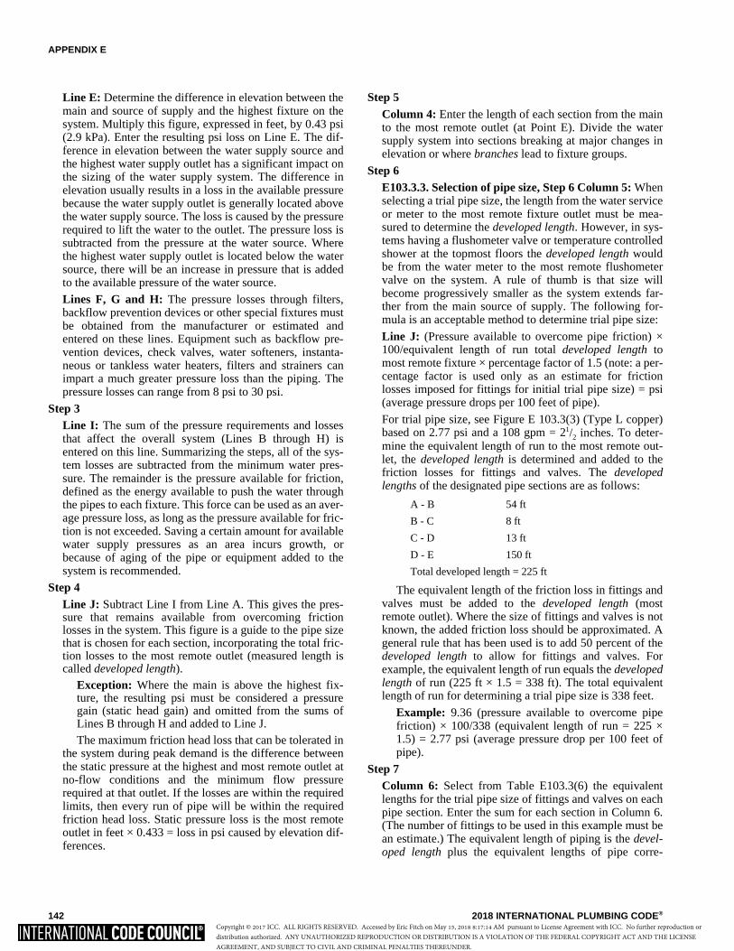
APPENDIX E
142 2018 INTERNATIONAL PLUMBING CODE®
Line E: Determine the difference in elevation between themain and source of supply and the highest fixture on thesystem. Multiply this figure, expressed in feet, by 0.43 psi(2.9 kPa). Enter the resulting psi loss on Line E. The dif-ference in elevation between the water supply source andthe highest water supply outlet has a significant impact onthe sizing of the water supply system. The difference inelevation usually results in a loss in the available pressurebecause the water supply outlet is generally located abovethe water supply source. The loss is caused by the pressurerequired to lift the water to the outlet. The pressure loss issubtracted from the pressure at the water source. Wherethe highest water supply outlet is located below the watersource, there will be an increase in pressure that is addedto the available pressure of the water source.
Lines F, G and H: The pressure losses through filters,backflow prevention devices or other special fixtures mustbe obtained from the manufacturer or estimated andentered on these lines. Equipment such as backflow pre-vention devices, check valves, water softeners, instanta-neous or tankless water heaters, filters and strainers canimpart a much greater pressure loss than the piping. Thepressure losses can range from 8 psi to 30 psi.
Step 3Line I: The sum of the pressure requirements and lossesthat affect the overall system (Lines B through H) isentered on this line. Summarizing the steps, all of the sys-tem losses are subtracted from the minimum water pres-sure. The remainder is the pressure available for friction,defined as the energy available to push the water throughthe pipes to each fixture. This force can be used as an aver-age pressure loss, as long as the pressure available for fric-tion is not exceeded. Saving a certain amount for availablewater supply pressures as an area incurs growth, orbecause of aging of the pipe or equipment added to thesystem is recommended.
Step 4Line J: Subtract Line I from Line A. This gives the pres-sure that remains available from overcoming frictionlosses in the system. This figure is a guide to the pipe sizethat is chosen for each section, incorporating the total fric-tion losses to the most remote outlet (measured length iscalled developed length).
Exception: Where the main is above the highest fix-ture, the resulting psi must be considered a pressuregain (static head gain) and omitted from the sums ofLines B through H and added to Line J.The maximum friction head loss that can be tolerated in
the system during peak demand is the difference betweenthe static pressure at the highest and most remote outlet atno-flow conditions and the minimum flow pressurerequired at that outlet. If the losses are within the requiredlimits, then every run of pipe will be within the requiredfriction head loss. Static pressure loss is the most remoteoutlet in feet × 0.433 = loss in psi caused by elevation dif-ferences.
Step 5Column 4: Enter the length of each section from the mainto the most remote outlet (at Point E). Divide the watersupply system into sections breaking at major changes inelevation or where branches lead to fixture groups.
Step 6E103.3.3. Selection of pipe size, Step 6 Column 5: Whenselecting a trial pipe size, the length from the water serviceor meter to the most remote fixture outlet must be mea-sured to determine the developed length. However, in sys-tems having a flushometer valve or temperature controlledshower at the topmost floors the developed length wouldbe from the water meter to the most remote flushometervalve on the system. A rule of thumb is that size willbecome progressively smaller as the system extends far-ther from the main source of supply. The following for-mula is an acceptable method to determine trial pipe size:
Line J: (Pressure available to overcome pipe friction) ×100/equivalent length of run total developed length tomost remote fixture × percentage factor of 1.5 (note: a per-centage factor is used only as an estimate for frictionlosses imposed for fittings for initial trial pipe size) = psi(average pressure drops per 100 feet of pipe).
For trial pipe size, see Figure E 103.3(3) (Type L copper)based on 2.77 psi and a 108 gpm = 21/2 inches. To deter-mine the equivalent length of run to the most remote out-let, the developed length is determined and added to thefriction losses for fittings and valves. The developedlengths of the designated pipe sections are as follows:
The equivalent length of the friction loss in fittings andvalves must be added to the developed length (mostremote outlet). Where the size of fittings and valves is notknown, the added friction loss should be approximated. Ageneral rule that has been used is to add 50 percent of thedeveloped length to allow for fittings and valves. Forexample, the equivalent length of run equals the developedlength of run (225 ft × 1.5 = 338 ft). The total equivalentlength of run for determining a trial pipe size is 338 feet.
Example: 9.36 (pressure available to overcome pipefriction) × 100/338 (equivalent length of run = 225 ×1.5) = 2.77 psi (average pressure drop per 100 feet ofpipe).
Step 7Column 6: Select from Table E103.3(6) the equivalentlengths for the trial pipe size of fittings and valves on eachpipe section. Enter the sum for each section in Column 6.(The number of fittings to be used in this example must bean estimate.) The equivalent length of piping is the devel-oped length plus the equivalent lengths of pipe corre-
A - B 54 ft
B - C 8 ft
C - D 13 ft
D - E 150 ft
Total developed length = 225 ft
Copyright © 2017 ICC. ALL RIGHTS RESERVED. Accessed by Eric Fitch on May 15, 2018 8:17:14 AM pursuant to License Agreement with ICC. No further reproduction ordistribution authorized. ANY UNAUTHORIZED REPRODUCTION OR DISTRIBUTION IS A VIOLATION OF THE FEDERAL COPYRIGHT ACT AND THE LICENSEAGREEMENT, AND SUBJECT TO CIVIL AND CRIMINAL PENALTIES THEREUNDER.
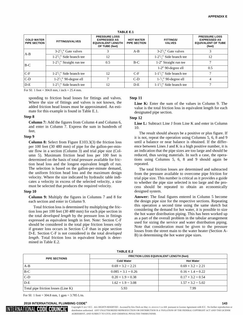
APPENDIX E
2018 INTERNATIONAL PLUMBING CODE® 143
sponding to friction head losses for fittings and valves.Where the size of fittings and valves is not known, theadded friction head losses must be approximated. An esti-mate for this example is found in Table E.1.
Step 8Column 7: Add the figures from Column 4 and Column 6,and enter in Column 7. Express the sum in hundreds offeet.
Step 9Column 8: Select from Figure E103.3(3) the friction lossper 100 feet (30 480 mm) of pipe for the gallon-per-min-ute flow in a section (Column 3) and trial pipe size (Col-umn 5). Maximum friction head loss per 100 feet isdetermined on the basis of total pressure available for fric-tion head loss and the longest equivalent length of run.The selection is based on the gallon-per-minute demand,the uniform friction head loss and the maximum designvelocity. Where the size indicated by hydraulic table indi-cates a velocity in excess of the selected velocity, a sizemust be selected that produces the required velocity.
Step 10Column 9: Multiply the figures in Columns 7 and 8 foreach section and enter in Column 9.
Total friction loss is determined by multiplying the fric-tion loss per 100 feet (30 480 mm) for each pipe section inthe total developed length by the pressure loss in fittingsexpressed as equivalent length in feet. Note: Section C-Fshould be considered in the total pipe friction losses onlyif greater loss occurs in Section C-F than in pipe sectionD-E. Section C-F is not considered in the total developedlength. Total friction loss in equivalent length is deter-mined in Table E.2.
Step 11Line K: Enter the sum of the values in Column 9. Thevalue is the total friction loss in equivalent length for eachdesignated pipe section.
Step 12Line L: Subtract Line J from Line K and enter in Column10.
The result should always be a positive or plus figure. Ifit is not, repeat the operation using Columns 5, 6, 8 and 9until a balance or near balance is obtained. If the differ-ence between Lines J and K is a high positive number, it isan indication that the pipe sizes are too large and should bereduced, thus saving materials. In such a case, the opera-tions using Columns 5, 6, 8 and 9 should again berepeated.
The total friction losses are determined and subtractedfrom the pressure available to overcome pipe friction fortrial pipe size. This number is critical as it provides a guideto whether the pipe size selected is too large and the pro-cess should be repeated to obtain an economicallydesigned system.
Answer: The final figures entered in Column 5 becomethe design pipe size for the respective sections. Repeatingthis operation a second time using the same sketch butconsidering the demand for hot water, it is possible to sizethe hot water distribution piping. This has been worked upas a part of the overall problem in the tabular arrangementused for sizing the service and water distribution piping.Note that consideration must be given to the pressurelosses from the street main to the water heater (Section A-B) in determining the hot water pipe sizes.
TABLE E.1
For SI: 1 foot = 304.8 mm, i inch = 25.4 mm.
COLD WATER PIPE SECTION FITTINGS/VALVES
PRESSURE LOSS EXPRESSED AS
EQUIVALENT LENGTH OF TUBE (feet)
HOT WATER PIPE SECTION
FITTINGS/VALVES
PRESSURE LOSS EXPRESSED AS
EQUIVALENT OF TUBE (feet)
A-B3-21/2″ Gate valves 3 A-B 3-21/2″ Gate valves 3
1-21/2″ Side branch tee 12 1-21/2″ Side branch tee 12
B-C1-21/2″ Straight run tee 0.5 B-C 1-2″ Straight run tee 7
1-2″ 90-degree ell 0.5
C-F 1-21/2″ Side branch tee 12 C-F 1-11/2″ Side branch tee 7
C-D 1-21/2″ 90-degree ell 7 C-D 1-1/2″ 90-degree ell 4
D-E 1-21/2″ Side branch tee 12 D-E 1-11/2″ Side branch tee 7
TABLE E.2
For SI: 1 foot = 304.8 mm, 1 gpm = 3.785 L/m.
PIPE SECTIONSFRICTION LOSS EQUIVALENT LENGTH (feet)
Cold Water Hot Water
A-B 0.69 × 3.2 = 2.21 0.69 × 3.2 = 2.21
B-C 0.085 × 3.1 = 0.26 0.16 × 1.4 = 0.22
C-D 0.20 × 1.9 = 0.38 0.17 × 3.2 = 0.54
D-E 1.62 × 1.9 = 3.08 1.57 × 3.2 = 5.02
Total pipe friction losses (Line K) 5.93 7.99
Copyright © 2017 ICC. ALL RIGHTS RESERVED. Accessed by Eric Fitch on May 15, 2018 8:17:14 AM pursuant to License Agreement with ICC. No further reproduction ordistribution authorized. ANY UNAUTHORIZED REPRODUCTION OR DISTRIBUTION IS A VIOLATION OF THE FEDERAL COPYRIGHT ACT AND THE LICENSEAGREEMENT, AND SUBJECT TO CIVIL AND CRIMINAL PENALTIES THEREUNDER.
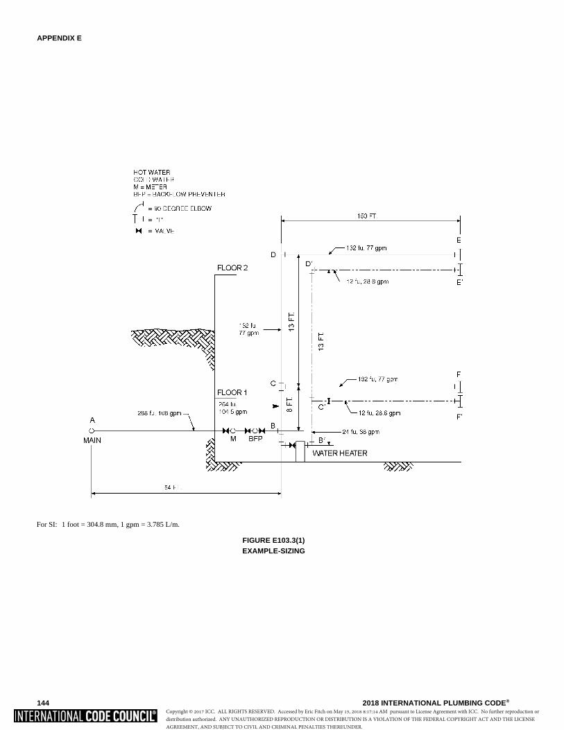
APPENDIX E
144 2018 INTERNATIONAL PLUMBING CODE®
For SI: 1 foot = 304.8 mm, 1 gpm = 3.785 L/m.
FIGURE E103.3(1)EXAMPLE-SIZING
Copyright © 2017 ICC. ALL RIGHTS RESERVED. Accessed by Eric Fitch on May 15, 2018 8:17:14 AM pursuant to License Agreement with ICC. No further reproduction ordistribution authorized. ANY UNAUTHORIZED REPRODUCTION OR DISTRIBUTION IS A VIOLATION OF THE FEDERAL COPYRIGHT ACT AND THE LICENSEAGREEMENT, AND SUBJECT TO CIVIL AND CRIMINAL PENALTIES THEREUNDER.
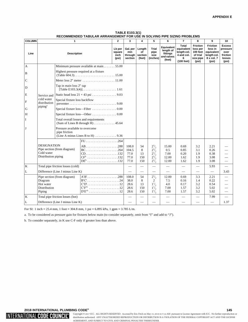
APPENDIX E
2018 INTERNATIONAL PLUMBING CODE® 145
TABLE E103.3(1)RECOMMENDED TABULAR ARRANGEMENT FOR USE IN SOLVING PIPE SIZING PROBLEMS
For SI: 1 inch = 25.4 mm, 1 foot = 304.8 mm, 1 psi = 6.895 kPa, 1 gpm = 3.785 L/m.
a. To be considered as pressure gain for fixtures below main (to consider separately, omit from “I” and add to “J”).
b. To consider separately, in K use C-F only if greater loss than above.
COLUMN 1 2 3 4 5 6 7 8 9 10
Line Description
Lb per square
inch (psi)
Gal. per min
through section
Length of
section (feet)
Trial pipe size
(inches)
Equivalent length of fittings
and valves (feet)
Total equivalent length col. 4 and col.
6 (100 feet)
Friction loss per 100 feet of trial
size pipe (psi)
Friction loss in
equivalent length col. 8 x col. 7
(psi)
Excess pressure
over friction losses (psi)
A
Service and cold water distribution pipinga
Minimum pressure available at main . . . . . . . 55.00
BHighest pressure required at a fixture (Table 604.3). . . . . . . . . . . . . . . . . . . . . . . . . 15.00
C Meter loss 2″ meter . . . . . . . . . . . . . . . . . . . . 11.00
DTap in main loss 2″ tap
[Table E103.3(4)]. . . . . . . . . . . . . . . . . . . . . 1.61
E Static head loss 21 × 43 psi . . . . . . . . . . . . . . . 9.03
FSpecial fixture loss backflow preventer . . . . . . . . . . . . . . . . . . . . . . . . . . . . . 9.00
G Special fixture loss—Filter . . . . . . . . . . . . . . . 0.00
H Special fixture loss—Other . . . . . . . . . . . . . . . 0.00
I Total overall losses and requirements (Sum of Lines B through H) . . . . . . . . . . . . . 45.64
J Pressure available to overcome pipe friction (Line A minus Lines B to H) . . . . . . . . . . . . . 9.36
DESIGNATIONPipe section (from diagram)Cold waterDistribution piping
FU . . . . . . . . . . . . . . . . . . . .264
AB. . . . . . . . . . . . . . . . . . . .288BC . . . . . . . . . . . . . . . . . . . .264CD. . . . . . . . . . . . . . . . . . . .132CFb . . . . . . . . . . . . . . . . . . .132DEb . . . . . . . . . . . . . . . . . . .132
108.0104.577.077.077.0
548
13150150
21/2
21/2
21/2
21/2
21/2
15.000.5
7.0012.0012.00
0.690.850.201.621.62
3.23.11.91.91.9
2.210.260.383.083.08
—————
K Total pipe friction losses (cold) — — — — — — 5.93 —
L Difference (Line J minus Line K) — — — — — — — 3.43
Pipe section (from diagram) DiagramHot waterDistributionPiping
A′B′ . . . . . . . . . . . . . . . . . . .288B′C′ . . . . . . . . . . . . . . . . . . . .24C′D′ . . . . . . . . . . . . . . . . . . . .12C′F′b . . . . . . . . . . . . . . . . . . .12D′E′b . . . . . . . . . . . . . . . . . . .12
108.038.028.628.628.6
548
13150150
21/2
211/2
11/2
11/2
12.007.54.0
7.007.00
0.690.160.171.571.57
3.31.43.23.23.2
2.210.220.545.025.02
—————
K Total pipe friction losses (hot) — — — — — — 7.99 —
L Difference (Line J minus Line K) — — — — — — — 1.37
Copyright © 2017 ICC. ALL RIGHTS RESERVED. Accessed by Eric Fitch on May 15, 2018 8:17:14 AM pursuant to License Agreement with ICC. No further reproduction ordistribution authorized. ANY UNAUTHORIZED REPRODUCTION OR DISTRIBUTION IS A VIOLATION OF THE FEDERAL COPYRIGHT ACT AND THE LICENSEAGREEMENT, AND SUBJECT TO CIVIL AND CRIMINAL PENALTIES THEREUNDER.

APPENDIX E
146 2018 INTERNATIONAL PLUMBING CODE®
TABLE E103.3(2)LOAD VALUES ASSIGNED TO FIXTURESa
For SI: 1 inch = 25.4 mm, 1 pound = 0.454 kg.a. For fixtures not listed, loads should be assumed by comparing the fixture to one listed using water in similar quantities and at similar rates. The assigned loads
for fixtures with both hot and cold water supplies are given for separate hot and cold water loads and for total load. The separate hot and cold water loadsbeing three-fourths of the total load for the fixture in each case.
FIXTURE OCCUPANCY TYPE OF SUPPLY CONTROL
LOAD VALUES, IN WATER SUPPLY FIXTURE UNITS (wsfu)
Cold Hot Total
Bathroom group Private Flush tank 2.7 1.5 3.6
Bathroom group Private Flushometer valve 6.0 3.0 8.0
Bathtub Private Faucet 1.0 1.0 1.4
Bathtub Public Faucet 3.0 3.0 4.0
Bidet Private Faucet 1.5 1.5 2.0
Combination fixture Private Faucet 2.25 2.25 3.0
Dishwashing machine Private Automatic — 1.4 1.4
Drinking fountain Offices, etc. 3/8″ valve 0.25 — 0.25
Kitchen sink Private Faucet 1.0 1.0 1.4
Kitchen sink Hotel, restaurant Faucet 3.0 3.0 4.0
Laundry trays (1 to 3) Private Faucet 1.0 1.0 1.4
Lavatory Private Faucet 0.5 0.5 0.7
Lavatory Public Faucet 1.5 1.5 2.0
Service sink Offices, etc. Faucet 2.25 2.25 3.0
Shower head Public Mixing valve 3.0 3.0 4.0
Shower head Private Mixing valve 1.0 1.0 1.4
Urinal Public 1″ flushometer valve 10.0 — 10.0
Urinal Public 3/4″ flushometer valve
5.0 — 5.0
Urinal Public Flush tank 3.0 — 3.0
Washing machine (8 lb) Private Automatic 1.0 1.0 1.4
Washing machine (8 lb) Public Automatic 2.25 2.25 3.0
Washing machine (15 lb) Public Automatic 3.0 3.0 4.0
Water closet Private Flushometer valve 6.0 — 6.0
Water closet Private Flush tank 2.2 — 2.2
Water closet Public Flushometer valve 10.0 — 10.0
Water closet Public Flush tank 5.0 — 5.0
Water closet Public or private Flushometer tank 2.0 — 2.0
Copyright © 2017 ICC. ALL RIGHTS RESERVED. Accessed by Eric Fitch on May 15, 2018 8:17:14 AM pursuant to License Agreement with ICC. No further reproduction ordistribution authorized. ANY UNAUTHORIZED REPRODUCTION OR DISTRIBUTION IS A VIOLATION OF THE FEDERAL COPYRIGHT ACT AND THE LICENSEAGREEMENT, AND SUBJECT TO CIVIL AND CRIMINAL PENALTIES THEREUNDER.
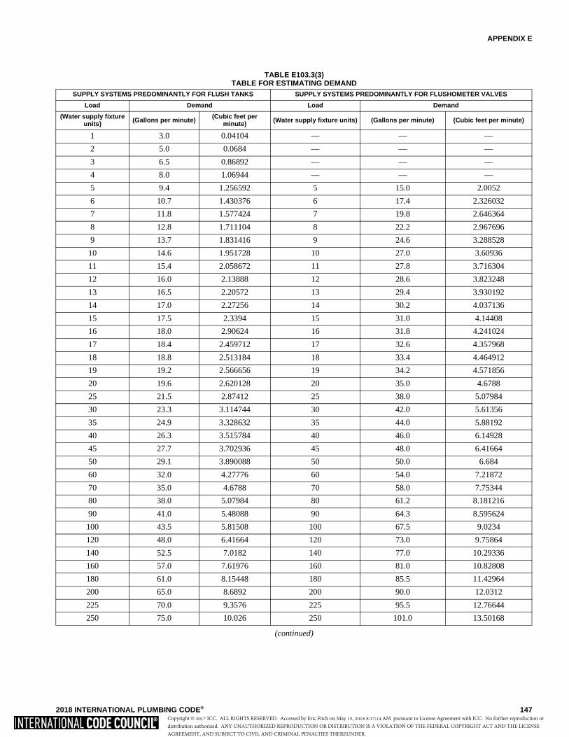
APPENDIX E
2018 INTERNATIONAL PLUMBING CODE® 147
TABLE E103.3(3)TABLE FOR ESTIMATING DEMAND
(continued)
SUPPLY SYSTEMS PREDOMINANTLY FOR FLUSH TANKS SUPPLY SYSTEMS PREDOMINANTLY FOR FLUSHOMETER VALVES
Load Demand Load Demand
(Water supply fixture units) (Gallons per minute) (Cubic feet per
minute) (Water supply fixture units) (Gallons per minute) (Cubic feet per minute)
1 3.0 0.04104 — — —
2 5.0 0.0684 — — —
3 6.5 0.86892 — — —
4 8.0 1.06944 — — —
5 9.4 1.256592 5 15.0 2.0052
6 10.7 1.430376 6 17.4 2.326032
7 11.8 1.577424 7 19.8 2.646364
8 12.8 1.711104 8 22.2 2.967696
9 13.7 1.831416 9 24.6 3.288528
10 14.6 1.951728 10 27.0 3.60936
11 15.4 2.058672 11 27.8 3.716304
12 16.0 2.13888 12 28.6 3.823248
13 16.5 2.20572 13 29.4 3.930192
14 17.0 2.27256 14 30.2 4.037136
15 17.5 2.3394 15 31.0 4.14408
16 18.0 2.90624 16 31.8 4.241024
17 18.4 2.459712 17 32.6 4.357968
18 18.8 2.513184 18 33.4 4.464912
19 19.2 2.566656 19 34.2 4.571856
20 19.6 2.620128 20 35.0 4.6788
25 21.5 2.87412 25 38.0 5.07984
30 23.3 3.114744 30 42.0 5.61356
35 24.9 3.328632 35 44.0 5.88192
40 26.3 3.515784 40 46.0 6.14928
45 27.7 3.702936 45 48.0 6.41664
50 29.1 3.890088 50 50.0 6.684
60 32.0 4.27776 60 54.0 7.21872
70 35.0 4.6788 70 58.0 7.75344
80 38.0 5.07984 80 61.2 8.181216
90 41.0 5.48088 90 64.3 8.595624
100 43.5 5.81508 100 67.5 9.0234
120 48.0 6.41664 120 73.0 9.75864
140 52.5 7.0182 140 77.0 10.29336
160 57.0 7.61976 160 81.0 10.82808
180 61.0 8.15448 180 85.5 11.42964
200 65.0 8.6892 200 90.0 12.0312
225 70.0 9.3576 225 95.5 12.76644
250 75.0 10.026 250 101.0 13.50168
Copyright © 2017 ICC. ALL RIGHTS RESERVED. Accessed by Eric Fitch on May 15, 2018 8:17:14 AM pursuant to License Agreement with ICC. No further reproduction ordistribution authorized. ANY UNAUTHORIZED REPRODUCTION OR DISTRIBUTION IS A VIOLATION OF THE FEDERAL COPYRIGHT ACT AND THE LICENSEAGREEMENT, AND SUBJECT TO CIVIL AND CRIMINAL PENALTIES THEREUNDER.

APPENDIX E
148 2018 INTERNATIONAL PLUMBING CODE®
TABLE E103.3(3)-continuedTABLE FOR ESTIMATING DEMAND
For SI: 1 inch = 25.4 mm, 1 gallon per minute = 3.785 L/m, 1 cubic foot per minute = 0.28 m3 per minute.
TABLE E103.3(4)LOSS OF PRESSURE THROUGH TAPS AND TEES IN POUNDS PER SQUARE INCH (psi)
For SI: 1 inch = 25.4 mm, 1 pound per square inch = 6.895 kpa, 1 gallon per minute = 3.785 L/m.
SUPPLY SYSTEMS PREDOMINANTLY FOR FLUSH TANKS SUPPLY SYSTEMS PREDOMINANTLY FOR FLUSHOMETER VALVES
Load Demand Load Demand
(Water supply fixture units) (Gallons per minute) (Cubic feet per minute) (Water supply fixture
units) (Gallons per minute) (Cubic feet per minute)
275 80.0 10.6944 275 104.5 13.96956
300 85.0 11.3628 300 108.0 14.43744
400 105.0 14.0364 400 127.0 16.97736
500 124.0 16.57632 500 143.0 19.11624
750 170.0 22.7256 750 177.0 23.66136
1,000 208.0 27.80544 1,000 208.0 27.80544
1,250 239.0 31.94952 1,250 239.0 31.94952
1,500 269.0 35.95992 1,500 269.0 35.95992
1,750 297.0 39.70296 1,750 297.0 39.70296
2,000 325.0 43.446 2,000 325.0 43.446
2,500 380.0 50.7984 2,500 380.0 50.7984
3,000 433.0 57.88344 3,000 433.0 57.88344
4,000 525.0 70.182 4,000 525.0 70.182
5,000 593.0 79.27224 5,000 593.0 79.27224
GALLONS PER MINUTESIZE OF TAP OR TEE (inches)
5/83/4 1 11/4 11/2 2 3
10 1.35 0.64 0.18 0.08 — — —
20 5.38 2.54 0.77 0.31 0.14 — —
30 12.10 5.72 1.62 0.69 0.33 0.10 —
40 — 10.20 3.07 1.23 0.58 0.18 —
50 — 15.90 4.49 1.92 0.91 0.28 —
60 — — 6.46 2.76 1.31 0.40 —
70 — — 8.79 3.76 1.78 0.55 0.10
80 — — 11.50 4.90 2.32 0.72 0.13
90 — — 14.50 6.21 2.94 0.91 0.16
100 — — 17.94 7.67 3.63 1.12 0.21
120 — — 25.80 11.00 5.23 1.61 0.30
140 — — 35.20 15.00 7.12 2.20 0.41
150 — — — 17.20 8.16 2.52 0.47
160 — — — 19.60 9.30 2.92 0.54
180 — — — 24.80 11.80 3.62 0.68
200 — — — 30.70 14.50 4.48 0.84
225 — — — 38.80 18.40 5.60 1.06
250 — — — 47.90 22.70 7.00 1.31
275 — — — — 27.40 7.70 1.59
300 — — — — 32.60 10.10 1.88
Copyright © 2017 ICC. ALL RIGHTS RESERVED. Accessed by Eric Fitch on May 15, 2018 8:17:14 AM pursuant to License Agreement with ICC. No further reproduction ordistribution authorized. ANY UNAUTHORIZED REPRODUCTION OR DISTRIBUTION IS A VIOLATION OF THE FEDERAL COPYRIGHT ACT AND THE LICENSEAGREEMENT, AND SUBJECT TO CIVIL AND CRIMINAL PENALTIES THEREUNDER.
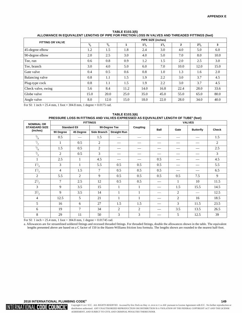
APPENDIX E
2018 INTERNATIONAL PLUMBING CODE® 149
TABLE E103.3(5)ALLOWANCE IN EQUIVALENT LENGTHS OF PIPE FOR FRICTION LOSS IN VALVES AND THREADED FITTINGS (feet)
For SI: 1 inch = 25.4 mm, 1 foot = 304.8 mm, 1 degree = 0.0175 rad.
TABLE E103.3(6)PRESSURE LOSS IN FITTINGS AND VALVES EXPRESSED AS EQUIVALENT LENGTH OF TUBEa (feet)
For SI: 1 inch = 25.4 mm, 1 foot = 304.8 mm, 1 degree = 0.01745 rad.a. Allowances are for streamlined soldered fittings and recessed threaded fittings. For threaded fittings, double the allowances shown in the table. The equivalent
lengths presented above are based on a C factor of 150 in the Hazen-Williams friction loss formula. The lengths shown are rounded to the nearest half-foot.
FITTING OR VALVEPIPE SIZE (inches)
1/23/4 1 11/4 11/2 2 21/2 3
45-degree elbow 1.2 1.5 1.8 2.4 3.0 4.0 5.0 6.0
90-degree elbow 2.0 2.5 3.0 4.0 5.0 7.0 8.0 10.0
Tee, run 0.6 0.8 0.9 1.2 1.5 2.0 2.5 3.0
Tee, branch 3.0 4.0 5.0 6.0 7.0 10.0 12.0 15.0
Gate valve 0.4 0.5 0.6 0.8 1.0 1.3 1.6 2.0
Balancing valve 0.8 1.1 1.5 1.9 2.2 3.0 3.7 4.5
Plug-type cock 0.8 1.1 1.5 1.9 2.2 3.0 3.7 4.5
Check valve, swing 5.6 8.4 11.2 14.0 16.8 22.4 28.0 33.6
Globe valve 15.0 20.0 25.0 35.0 45.0 55.0 65.0 80.0
Angle valve 8.0 12.0 15.0 18.0 22.0 28.0 34.0 40.0
NOMINAL OR STANDARD SIZE
(inches)
FITTINGS
Coupling
VALVES
Standard EII 90-Degree TeeBall Gate Butterfly Check
90 Degree 45 Degree Side Branch Straight Run3/8 0.5 — 1.5 — — — — — 1.51/2 1 0.5 2 — — — — — 25/8 1.5 0.5 2 — — — — — 2.53/4 2 0.5 3 — — — — — 3
1 2.5 1 4.5 — — 0.5 — — 4.5
11/4 3 1 5.5 0.5 0.5 0.5 — — 5.5
11/2 4 1.5 7 0.5 0.5 0.5 — — 6.5
2 5.5 2 9 0.5 0.5 0.5 0.5 7.5 9
21/2 7 2.5 12 0.5 0.5 — 1 10 11.5
3 9 3.5 15 1 1 — 1.5 15.5 14.5
31/2 9 3.5 14 1 1 — 2 — 12.5
4 12.5 5 21 1 1 — 2 16 18.5
5 16 6 27 1.5 1.5 — 3 11.5 23.5
6 19 7 34 2 2 — 3.5 13.5 26.5
8 29 11 50 3 3 — 5 12.5 39
Copyright © 2017 ICC. ALL RIGHTS RESERVED. Accessed by Eric Fitch on May 15, 2018 8:17:14 AM pursuant to License Agreement with ICC. No further reproduction ordistribution authorized. ANY UNAUTHORIZED REPRODUCTION OR DISTRIBUTION IS A VIOLATION OF THE FEDERAL COPYRIGHT ACT AND THE LICENSEAGREEMENT, AND SUBJECT TO CIVIL AND CRIMINAL PENALTIES THEREUNDER.
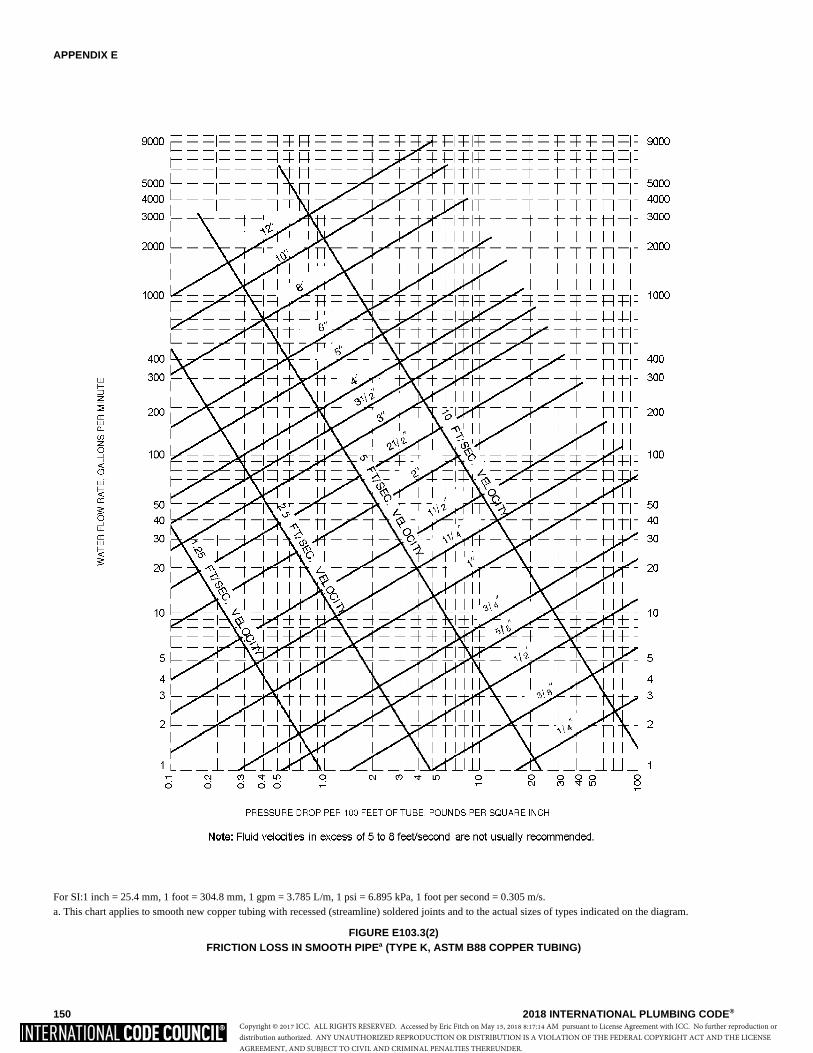
APPENDIX E
150 2018 INTERNATIONAL PLUMBING CODE®
For SI:1 inch = 25.4 mm, 1 foot = 304.8 mm, 1 gpm = 3.785 L/m, 1 psi = 6.895 kPa, 1 foot per second = 0.305 m/s.a. This chart applies to smooth new copper tubing with recessed (streamline) soldered joints and to the actual sizes of types indicated on the diagram.
FIGURE E103.3(2)FRICTION LOSS IN SMOOTH PIPEa (TYPE K, ASTM B88 COPPER TUBING)
Copyright © 2017 ICC. ALL RIGHTS RESERVED. Accessed by Eric Fitch on May 15, 2018 8:17:14 AM pursuant to License Agreement with ICC. No further reproduction ordistribution authorized. ANY UNAUTHORIZED REPRODUCTION OR DISTRIBUTION IS A VIOLATION OF THE FEDERAL COPYRIGHT ACT AND THE LICENSEAGREEMENT, AND SUBJECT TO CIVIL AND CRIMINAL PENALTIES THEREUNDER.
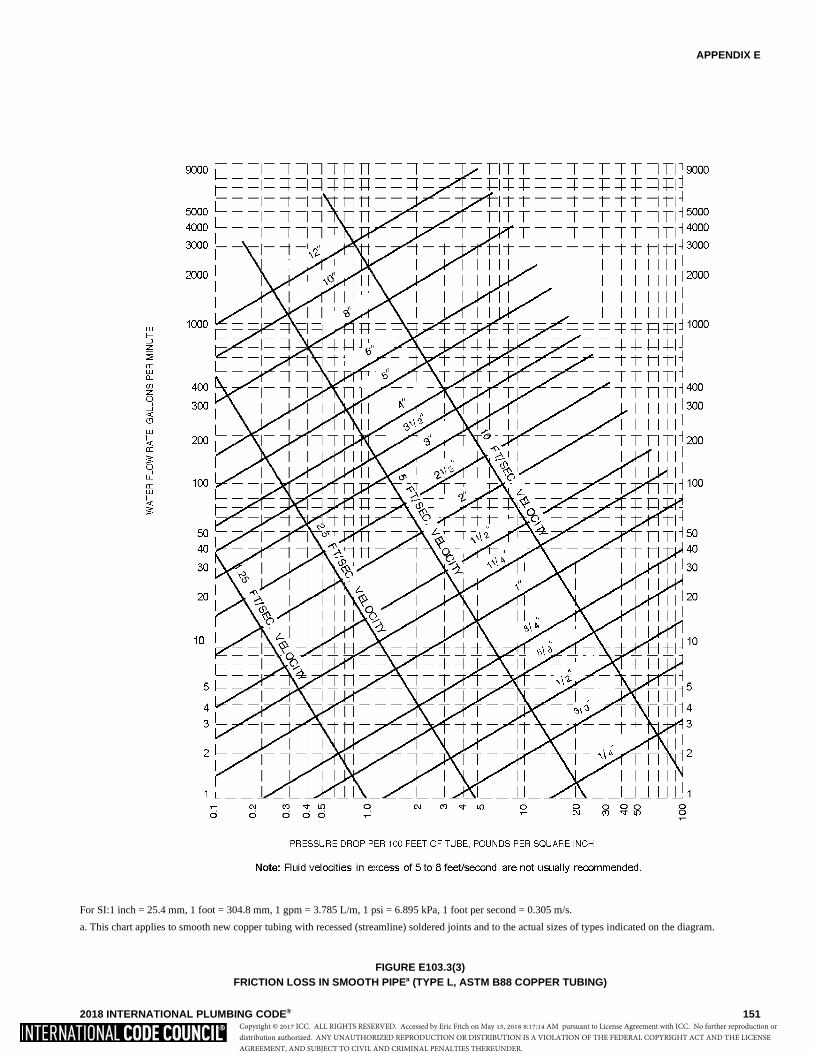
APPENDIX E
2018 INTERNATIONAL PLUMBING CODE® 151
For SI:1 inch = 25.4 mm, 1 foot = 304.8 mm, 1 gpm = 3.785 L/m, 1 psi = 6.895 kPa, 1 foot per second = 0.305 m/s.
a. This chart applies to smooth new copper tubing with recessed (streamline) soldered joints and to the actual sizes of types indicated on the diagram.
FIGURE E103.3(3)FRICTION LOSS IN SMOOTH PIPEa (TYPE L, ASTM B88 COPPER TUBING)
Copyright © 2017 ICC. ALL RIGHTS RESERVED. Accessed by Eric Fitch on May 15, 2018 8:17:14 AM pursuant to License Agreement with ICC. No further reproduction ordistribution authorized. ANY UNAUTHORIZED REPRODUCTION OR DISTRIBUTION IS A VIOLATION OF THE FEDERAL COPYRIGHT ACT AND THE LICENSEAGREEMENT, AND SUBJECT TO CIVIL AND CRIMINAL PENALTIES THEREUNDER.
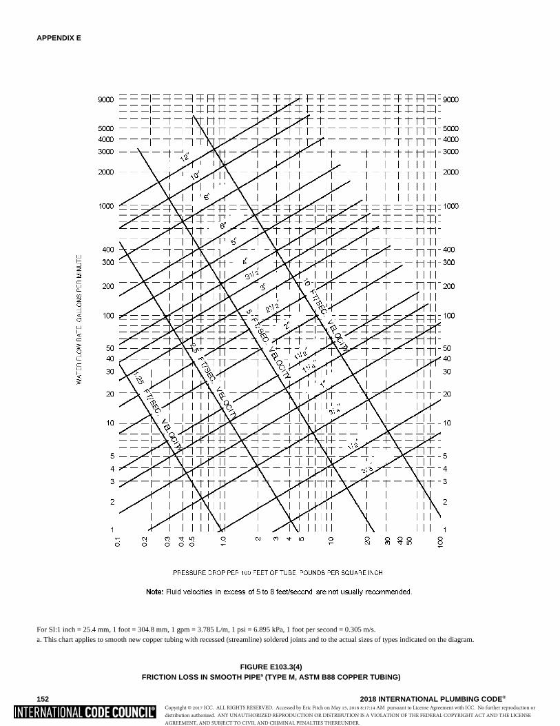
APPENDIX E
152 2018 INTERNATIONAL PLUMBING CODE®
For SI:1 inch = 25.4 mm, 1 foot = 304.8 mm, 1 gpm = 3.785 L/m, 1 psi = 6.895 kPa, 1 foot per second = 0.305 m/s.a. This chart applies to smooth new copper tubing with recessed (streamline) soldered joints and to the actual sizes of types indicated on the diagram.
FIGURE E103.3(4)FRICTION LOSS IN SMOOTH PIPEa (TYPE M, ASTM B88 COPPER TUBING)
Copyright © 2017 ICC. ALL RIGHTS RESERVED. Accessed by Eric Fitch on May 15, 2018 8:17:14 AM pursuant to License Agreement with ICC. No further reproduction ordistribution authorized. ANY UNAUTHORIZED REPRODUCTION OR DISTRIBUTION IS A VIOLATION OF THE FEDERAL COPYRIGHT ACT AND THE LICENSEAGREEMENT, AND SUBJECT TO CIVIL AND CRIMINAL PENALTIES THEREUNDER.
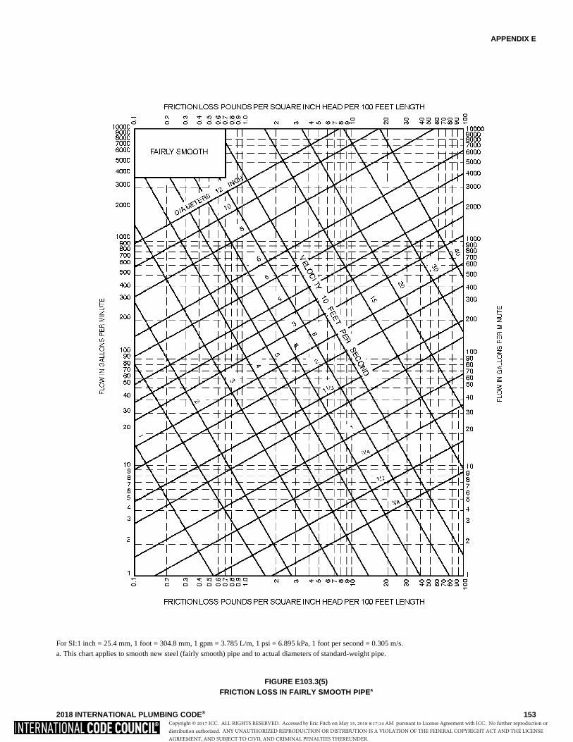
APPENDIX E
2018 INTERNATIONAL PLUMBING CODE® 153
For SI:1 inch = 25.4 mm, 1 foot = 304.8 mm, 1 gpm = 3.785 L/m, 1 psi = 6.895 kPa, 1 foot per second = 0.305 m/s.a. This chart applies to smooth new steel (fairly smooth) pipe and to actual diameters of standard-weight pipe.
FIGURE E103.3(5)FRICTION LOSS IN FAIRLY SMOOTH PIPEa
Copyright © 2017 ICC. ALL RIGHTS RESERVED. Accessed by Eric Fitch on May 15, 2018 8:17:14 AM pursuant to License Agreement with ICC. No further reproduction ordistribution authorized. ANY UNAUTHORIZED REPRODUCTION OR DISTRIBUTION IS A VIOLATION OF THE FEDERAL COPYRIGHT ACT AND THE LICENSEAGREEMENT, AND SUBJECT TO CIVIL AND CRIMINAL PENALTIES THEREUNDER.
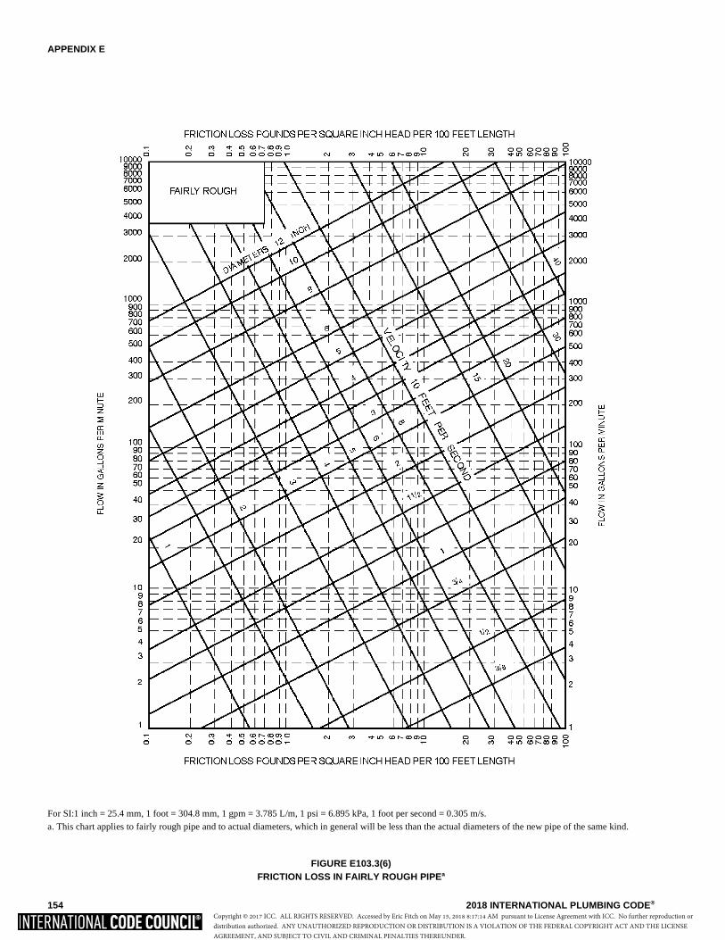
APPENDIX E
154 2018 INTERNATIONAL PLUMBING CODE®
For SI:1 inch = 25.4 mm, 1 foot = 304.8 mm, 1 gpm = 3.785 L/m, 1 psi = 6.895 kPa, 1 foot per second = 0.305 m/s.a. This chart applies to fairly rough pipe and to actual diameters, which in general will be less than the actual diameters of the new pipe of the same kind.
FIGURE E103.3(6)FRICTION LOSS IN FAIRLY ROUGH PIPEa
Copyright © 2017 ICC. ALL RIGHTS RESERVED. Accessed by Eric Fitch on May 15, 2018 8:17:14 AM pursuant to License Agreement with ICC. No further reproduction ordistribution authorized. ANY UNAUTHORIZED REPRODUCTION OR DISTRIBUTION IS A VIOLATION OF THE FEDERAL COPYRIGHT ACT AND THE LICENSEAGREEMENT, AND SUBJECT TO CIVIL AND CRIMINAL PENALTIES THEREUNDER.
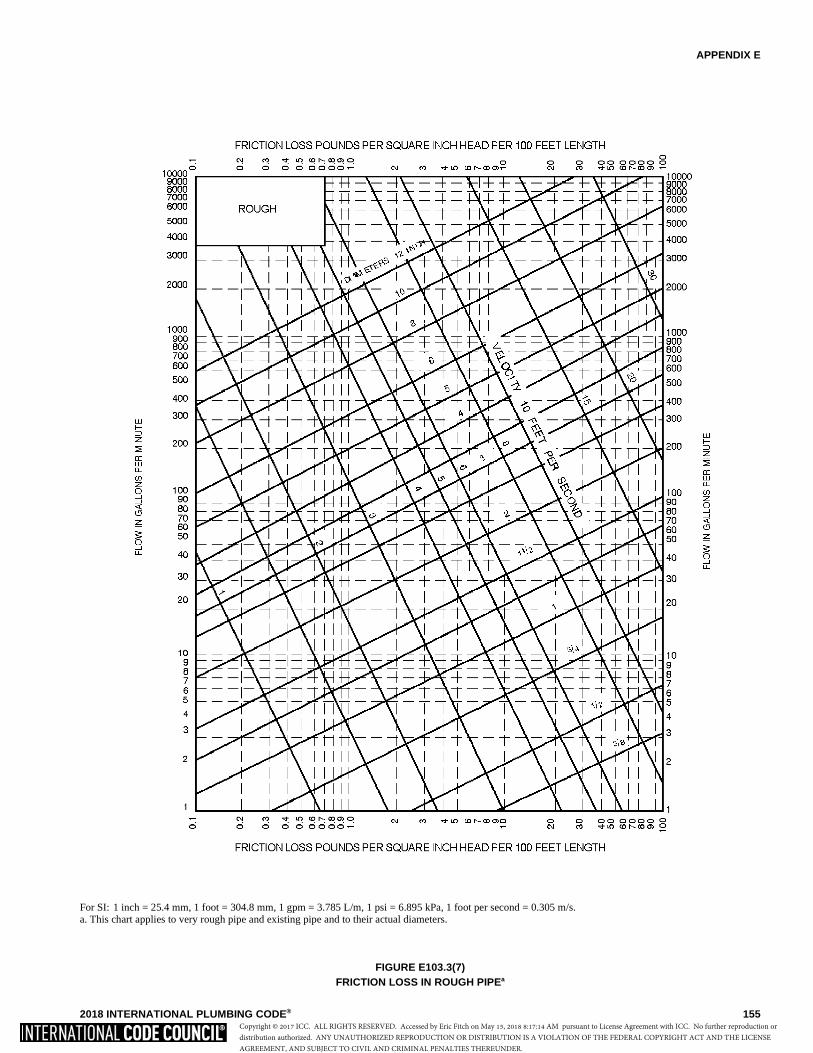
APPENDIX E
2018 INTERNATIONAL PLUMBING CODE® 155
For SI: 1 inch = 25.4 mm, 1 foot = 304.8 mm, 1 gpm = 3.785 L/m, 1 psi = 6.895 kPa, 1 foot per second = 0.305 m/s.a. This chart applies to very rough pipe and existing pipe and to their actual diameters.
FIGURE E103.3(7)FRICTION LOSS IN ROUGH PIPEa
Copyright © 2017 ICC. ALL RIGHTS RESERVED. Accessed by Eric Fitch on May 15, 2018 8:17:14 AM pursuant to License Agreement with ICC. No further reproduction ordistribution authorized. ANY UNAUTHORIZED REPRODUCTION OR DISTRIBUTION IS A VIOLATION OF THE FEDERAL COPYRIGHT ACT AND THE LICENSEAGREEMENT, AND SUBJECT TO CIVIL AND CRIMINAL PENALTIES THEREUNDER.
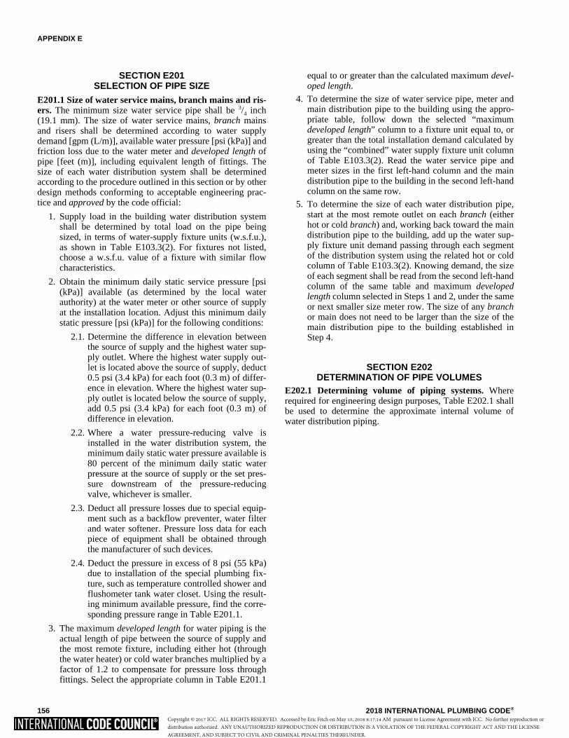
APPENDIX E
156 2018 INTERNATIONAL PLUMBING CODE®
SECTION E201SELECTION OF PIPE SIZE
E201.1 Size of water service mains, branch mains and ris-ers. The minimum size water service pipe shall be 3/4 inch(19.1 mm). The size of water service mains, branch mainsand risers shall be determined according to water supplydemand [gpm (L/m)], available water pressure [psi (kPa)] andfriction loss due to the water meter and developed length ofpipe [feet (m)], including equivalent length of fittings. Thesize of each water distribution system shall be determinedaccording to the procedure outlined in this section or by otherdesign methods conforming to acceptable engineering prac-tice and approved by the code official:
1. Supply load in the building water distribution systemshall be determined by total load on the pipe beingsized, in terms of water-supply fixture units (w.s.f.u.),as shown in Table E103.3(2). For fixtures not listed,choose a w.s.f.u. value of a fixture with similar flowcharacteristics.
2. Obtain the minimum daily static service pressure [psi(kPa)] available (as determined by the local waterauthority) at the water meter or other source of supplyat the installation location. Adjust this minimum dailystatic pressure [psi (kPa)] for the following conditions:
2.1. Determine the difference in elevation betweenthe source of supply and the highest water sup-ply outlet. Where the highest water supply out-let is located above the source of supply, deduct0.5 psi (3.4 kPa) for each foot (0.3 m) of differ-ence in elevation. Where the highest water sup-ply outlet is located below the source of supply,add 0.5 psi (3.4 kPa) for each foot (0.3 m) ofdifference in elevation.
2.2. Where a water pressure-reducing valve isinstalled in the water distribution system, theminimum daily static water pressure available is80 percent of the minimum daily static waterpressure at the source of supply or the set pres-sure downstream of the pressure-reducingvalve, whichever is smaller.
2.3. Deduct all pressure losses due to special equip-ment such as a backflow preventer, water filterand water softener. Pressure loss data for eachpiece of equipment shall be obtained throughthe manufacturer of such devices.
2.4. Deduct the pressure in excess of 8 psi (55 kPa)due to installation of the special plumbing fix-ture, such as temperature controlled shower andflushometer tank water closet. Using the result-ing minimum available pressure, find the corre-sponding pressure range in Table E201.1.
3. The maximum developed length for water piping is theactual length of pipe between the source of supply andthe most remote fixture, including either hot (throughthe water heater) or cold water branches multiplied by afactor of 1.2 to compensate for pressure loss throughfittings. Select the appropriate column in Table E201.1
equal to or greater than the calculated maximum devel-oped length.
4. To determine the size of water service pipe, meter andmain distribution pipe to the building using the appro-priate table, follow down the selected “maximumdeveloped length” column to a fixture unit equal to, orgreater than the total installation demand calculated byusing the “combined” water supply fixture unit columnof Table E103.3(2). Read the water service pipe andmeter sizes in the first left-hand column and the maindistribution pipe to the building in the second left-handcolumn on the same row.
5. To determine the size of each water distribution pipe,start at the most remote outlet on each branch (eitherhot or cold branch) and, working back toward the maindistribution pipe to the building, add up the water sup-ply fixture unit demand passing through each segmentof the distribution system using the related hot or coldcolumn of Table E103.3(2). Knowing demand, the sizeof each segment shall be read from the second left-handcolumn of the same table and maximum developedlength column selected in Steps 1 and 2, under the sameor next smaller size meter row. The size of any branchor main does not need to be larger than the size of themain distribution pipe to the building established inStep 4.
SECTION E202DETERMINATION OF PIPE VOLUMES
E202.1 Determining volume of piping systems. Whererequired for engineering design purposes, Table E202.1 shallbe used to determine the approximate internal volume ofwater distribution piping.
Copyright © 2017 ICC. ALL RIGHTS RESERVED. Accessed by Eric Fitch on May 15, 2018 8:17:14 AM pursuant to License Agreement with ICC. No further reproduction ordistribution authorized. ANY UNAUTHORIZED REPRODUCTION OR DISTRIBUTION IS A VIOLATION OF THE FEDERAL COPYRIGHT ACT AND THE LICENSEAGREEMENT, AND SUBJECT TO CIVIL AND CRIMINAL PENALTIES THEREUNDER.
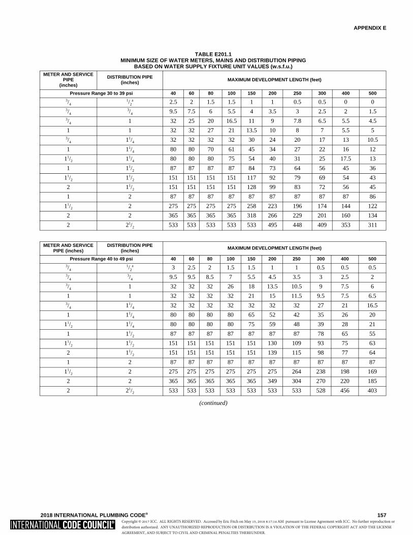
APPENDIX E
2018 INTERNATIONAL PLUMBING CODE® 157
TABLE E201.1MINIMUM SIZE OF WATER METERS, MAINS AND DISTRIBUTION PIPING
BASED ON WATER SUPPLY FIXTURE UNIT VALUES (w.s.f.u.)
(continued)
METER AND SERVICE PIPE
(inches)
DISTRIBUTION PIPE(inches) MAXIMUM DEVELOPMENT LENGTH (feet)
Pressure Range 30 to 39 psi 40 60 80 100 150 200 250 300 400 5003/4
1/2a 2.5 2 1.5 1.5 1 1 0.5 0.5 0 0
3/43/4 9.5 7.5 6 5.5 4 3.5 3 2.5 2 1.5
3/4 1 32 25 20 16.5 11 9 7.8 6.5 5.5 4.5
1 1 32 32 27 21 13.5 10 8 7 5.5 53/4 11/4 32 32 32 32 30 24 20 17 13 10.5
1 11/4 80 80 70 61 45 34 27 22 16 12
11/2 11/4 80 80 80 75 54 40 31 25 17.5 13
1 11/2 87 87 87 87 84 73 64 56 45 36
11/2 11/2 151 151 151 151 117 92 79 69 54 43
2 11/2 151 151 151 151 128 99 83 72 56 45
1 2 87 87 87 87 87 87 87 87 87 86
11/2 2 275 275 275 275 258 223 196 174 144 122
2 2 365 365 365 365 318 266 229 201 160 134
2 21/2 533 533 533 533 533 495 448 409 353 311
METER AND SERVICE PIPE (inches)
DISTRIBUTION PIPE(inches) MAXIMUM DEVELOPMENT LENGTH (feet)
Pressure Range 40 to 49 psi 40 60 80 100 150 200 250 300 400 5003/4
1/2a 3 2.5 2 1.5 1.5 1 1 0.5 0.5 0.5
3/43/4 9.5 9.5 8.5 7 5.5 4.5 3.5 3 2.5 2
3/4 1 32 32 32 26 18 13.5 10.5 9 7.5 6
1 1 32 32 32 32 21 15 11.5 9.5 7.5 6.53/4 11/4 32 32 32 32 32 32 32 27 21 16.5
1 11/4 80 80 80 80 65 52 42 35 26 20
11/2 11/4 80 80 80 80 75 59 48 39 28 21
1 11/2 87 87 87 87 87 87 87 78 65 55
11/2 11/2 151 151 151 151 151 130 109 93 75 63
2 11/2 151 151 151 151 151 139 115 98 77 64
1 2 87 87 87 87 87 87 87 87 87 87
11/2 2 275 275 275 275 275 275 264 238 198 169
2 2 365 365 365 365 365 349 304 270 220 185
2 21/2 533 533 533 533 533 533 533 528 456 403
Copyright © 2017 ICC. ALL RIGHTS RESERVED. Accessed by Eric Fitch on May 15, 2018 8:17:14 AM pursuant to License Agreement with ICC. No further reproduction ordistribution authorized. ANY UNAUTHORIZED REPRODUCTION OR DISTRIBUTION IS A VIOLATION OF THE FEDERAL COPYRIGHT ACT AND THE LICENSEAGREEMENT, AND SUBJECT TO CIVIL AND CRIMINAL PENALTIES THEREUNDER.
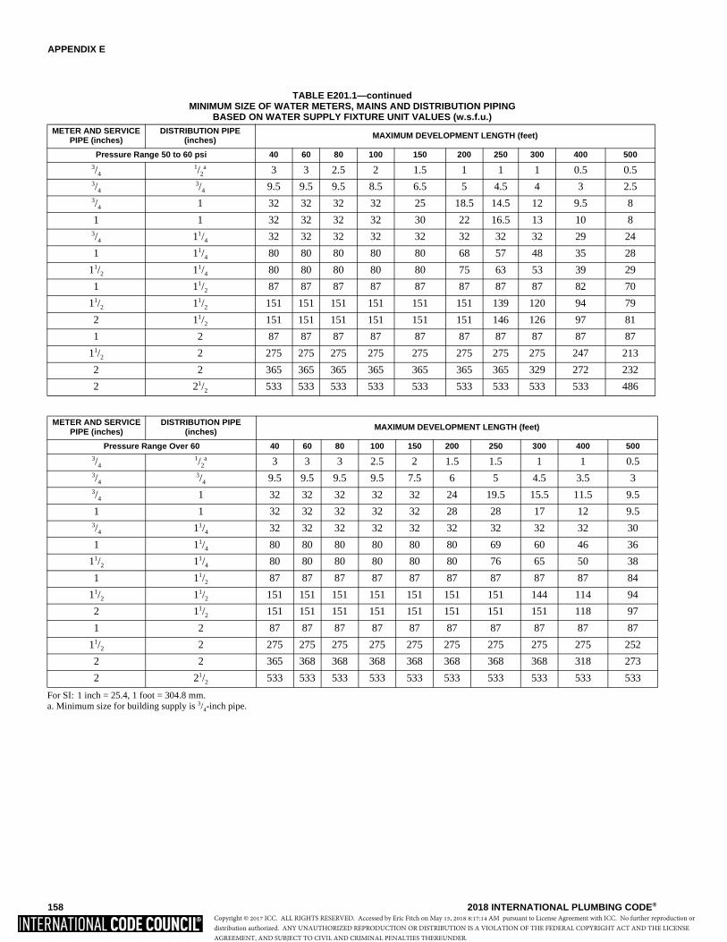
APPENDIX E
158 2018 INTERNATIONAL PLUMBING CODE®
TABLE E201.1—continuedMINIMUM SIZE OF WATER METERS, MAINS AND DISTRIBUTION PIPING
BASED ON WATER SUPPLY FIXTURE UNIT VALUES (w.s.f.u.)
For SI: 1 inch = 25.4, 1 foot = 304.8 mm.a. Minimum size for building supply is 3/4-inch pipe.
METER AND SERVICE PIPE (inches)
DISTRIBUTION PIPE(inches) MAXIMUM DEVELOPMENT LENGTH (feet)
Pressure Range 50 to 60 psi 40 60 80 100 150 200 250 300 400 5003/4
1/2a 3 3 2.5 2 1.5 1 1 1 0.5 0.5
3/43/4 9.5 9.5 9.5 8.5 6.5 5 4.5 4 3 2.5
3/4 1 32 32 32 32 25 18.5 14.5 12 9.5 8
1 1 32 32 32 32 30 22 16.5 13 10 83/4 11/4 32 32 32 32 32 32 32 32 29 24
1 11/4 80 80 80 80 80 68 57 48 35 28
11/2 11/4 80 80 80 80 80 75 63 53 39 29
1 11/2 87 87 87 87 87 87 87 87 82 70
11/2 11/2 151 151 151 151 151 151 139 120 94 79
2 11/2 151 151 151 151 151 151 146 126 97 81
1 2 87 87 87 87 87 87 87 87 87 87
11/2 2 275 275 275 275 275 275 275 275 247 213
2 2 365 365 365 365 365 365 365 329 272 232
2 21/2 533 533 533 533 533 533 533 533 533 486
METER AND SERVICE PIPE (inches)
DISTRIBUTION PIPE(inches) MAXIMUM DEVELOPMENT LENGTH (feet)
Pressure Range Over 60 40 60 80 100 150 200 250 300 400 5003/4
1/2a 3 3 3 2.5 2 1.5 1.5 1 1 0.5
3/43/4 9.5 9.5 9.5 9.5 7.5 6 5 4.5 3.5 3
3/4 1 32 32 32 32 32 24 19.5 15.5 11.5 9.5
1 1 32 32 32 32 32 28 28 17 12 9.53/4 11/4 32 32 32 32 32 32 32 32 32 30
1 11/4 80 80 80 80 80 80 69 60 46 36
11/2 11/4 80 80 80 80 80 80 76 65 50 38
1 11/2 87 87 87 87 87 87 87 87 87 84
11/2 11/2 151 151 151 151 151 151 151 144 114 94
2 11/2 151 151 151 151 151 151 151 151 118 97
1 2 87 87 87 87 87 87 87 87 87 87
11/2 2 275 275 275 275 275 275 275 275 275 252
2 2 365 368 368 368 368 368 368 368 318 273
2 21/2 533 533 533 533 533 533 533 533 533 533
Copyright © 2017 ICC. ALL RIGHTS RESERVED. Accessed by Eric Fitch on May 15, 2018 8:17:14 AM pursuant to License Agreement with ICC. No further reproduction ordistribution authorized. ANY UNAUTHORIZED REPRODUCTION OR DISTRIBUTION IS A VIOLATION OF THE FEDERAL COPYRIGHT ACT AND THE LICENSEAGREEMENT, AND SUBJECT TO CIVIL AND CRIMINAL PENALTIES THEREUNDER.
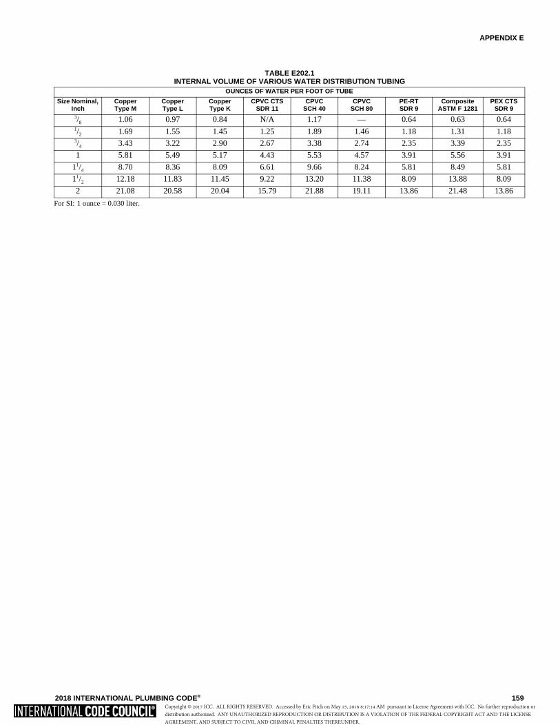
APPENDIX E
2018 INTERNATIONAL PLUMBING CODE® 159
TABLE E202.1INTERNAL VOLUME OF VARIOUS WATER DISTRIBUTION TUBING
For SI: 1 ounce = 0.030 liter.
OUNCES OF WATER PER FOOT OF TUBE
Size Nominal, Inch
Copper Type M
Copper Type L
Copper Type K
CPVC CTS SDR 11
CPVC SCH 40
CPVCSCH 80
PE-RTSDR 9
Composite ASTM F 1281
PEX CTS SDR 9
3/8 1.06 0.97 0.84 N/A 1.17 — 0.64 0.63 0.641/2 1.69 1.55 1.45 1.25 1.89 1.46 1.18 1.31 1.183/4 3.43 3.22 2.90 2.67 3.38 2.74 2.35 3.39 2.35
1 5.81 5.49 5.17 4.43 5.53 4.57 3.91 5.56 3.91
11/4 8.70 8.36 8.09 6.61 9.66 8.24 5.81 8.49 5.81
11/2 12.18 11.83 11.45 9.22 13.20 11.38 8.09 13.88 8.09
2 21.08 20.58 20.04 15.79 21.88 19.11 13.86 21.48 13.86
Copyright © 2017 ICC. ALL RIGHTS RESERVED. Accessed by Eric Fitch on May 15, 2018 8:17:14 AM pursuant to License Agreement with ICC. No further reproduction ordistribution authorized. ANY UNAUTHORIZED REPRODUCTION OR DISTRIBUTION IS A VIOLATION OF THE FEDERAL COPYRIGHT ACT AND THE LICENSEAGREEMENT, AND SUBJECT TO CIVIL AND CRIMINAL PENALTIES THEREUNDER.

160 2018 INTERNATIONAL PLUMBING CODE®
Copyright © 2017 ICC. ALL RIGHTS RESERVED. Accessed by Eric Fitch on May 15, 2018 8:17:14 AM pursuant to License Agreement with ICC. No further reproduction ordistribution authorized. ANY UNAUTHORIZED REPRODUCTION OR DISTRIBUTION IS A VIOLATION OF THE FEDERAL COPYRIGHT ACT AND THE LICENSEAGREEMENT, AND SUBJECT TO CIVIL AND CRIMINAL PENALTIES THEREUNDER.
2018 INTERNATIONAL PLUMBING CODE® 161
INDEX
AABS PIPE
Approved standards . . . . . . . . . . . . . . . . Table 605.3,Table 605.5, Table 702.1, Table 702.2,
Table 702.3, Table 702.4,Table 1102.4, Table 1102.7
Support . . . . . . . . . . . . . . . . . . . . . . . . . . .Table 308.5ACCESS TO
Air admittance valve . . . . . . . . . . . . . . . . . . . . …918.5Appliances . . . . . . . . . . . . . . . . . . . . . . . . . . . . .502.5Backflow preventers . . . . . . . . . . . . . . . . . . . . .608.14Backwater valve . . . . . . . . . . . . . . . . . . . . . . . . .714.3Cleanouts . . . . . . . . . . . . . . . . . . . . .708.1.10, 1103.4Filters . . . . . . . . . . ..1302.5, 1302.9, 1303.8, 1303.12First-flush diverter . . . . . . . . . . . . . . . . . . . . . . .1303.4Fixtures. . . . . . . . . . . . . . . . . . . . . . . . . . . . . . . .405.2Flexible water connectors . . . . . . . . . . . . . . . . . .605.6Floor drain . . . . . . . . . . . . . . . . . . . . . . . . . . . . .413.2Flush tank components . . . . . . . . . . . . . . . . . 415.3.4Grease removal devices. . . . . . . . . . . . . . . . 1003.3.6Interceptors and separators . . . . . . . 1003.5, 1003.10Manifolds . . . . . . . . . . . . . . . . . . . . . . . . . . . 604.10.3Pumps . . . . . . . . . . . . . . . . . . . . . . . .602.3.5, 1302.9Reservoir or interior . . . . . . . . . . . . . . . . . . . 1301.9.6Shower compartment . . . . . . . . . . . . . . . . . . . 421.4.2Slip joints . . . . . . . . . . . . . . . . . . . . . . . . . . . . . .405.9Standpipes . . . . . . . . . . . . . . . . . . . . . . . . . . . 802.4.3Sump . . . . . . . . . . . . . . . . . . . . . . . . . . . . . . . 712.3.2Vacuum breakers . . . . . . . . . . . . . . . . . . . . . . . .415.2Vacuum station . . . . . . . . . . . . . . . . . . . . . . . . . .713.4Valves. . . . . . . . . . . . . . .503.1, 604.11, 606.3, 712.2,
715.5, 918.5, 1302.8.1, 1302.9, 1303.12Waste receptors . . . . . . . . . . . . . . . . . . . . . . . . .802.4Water heaters . . . . . . . . . . . . . . . . . . . . . 502.3, 502.5Whirlpool pump. . . . . . . . . . . . . . . . . . . . . . . . . .426.5
ACCESSIBLE . . . . . . . . . . . . . . . . . . . . . . . . . . . . . 202ACCESSIBLE PLUMBING FACILITIES
Clearances . . . . . . . . . . . . . . . . . . . . . .404.2, 405.3.1Protection required . . . . . . . . . . . . . . . . . . . . . . .404.3Route . . . . . . . . . . . . . . . . . . . . . . . . . . . . . . . . .403.5Signs. . . . . . . . . . . . . . . . . . . . . . . . . . . . . . . . . .403.4Where required. . . . . . . . . . . . . . . . . . . . . . . . . .404.1
ADMINISTRATIONApplicability. . . . . . . . . . . . . . . . . . . . . . . . . . . . . . 102Approval . . . . . . . . . . . . . . . . . . . .105, 106.5.7, 107.5Inspections . . . . . . . . . . . . . . . . . . . . . . . . . . . . . . 107
Intent . . . . . . . . . . . . . . . . . . . . . . . . . . . . 101.3, 109.1Maintenance . . . . . . . . . . . . . . . . . . . . . . . . . . . 102.3Means of appeal . . . . . . . . . . . . . . . . . . . . . . . . . . 109Scope . . . . . . . . . . . . . . . . . . . . . . . . . . . . . . . . 101.2Validity . . . . . . . . . . . . . . . . . . . . . . . . . . . . . . 106.5.2Violations . . . . . . . . . . . . . . . . . . . . . . . . . . . . . . . 108
AIR ADMITTANCE VALVEChemical waste. . . . . . . . . . . . . . . . . . . . . . . . . 901.3Definition . . . . . . . . . . . . . . . . . . . . . . . . . . . . . . . . 202Where permitted . . . . . . . . . . . . . . . 905.1, 917.6, 918
AIR BREAKDefinition . . . . . . . . . . . . . . . . . . . . . . . . . . . . . . . . 202Method of providing . . . . . . . . . . . . 802.1.5, 802.1.6,
802.1.7Where required . . . . 406.2, 802.1.2, 802.1.5, 802.3.2
AIR GAPAnnual inspection of . . . . . . . . . . . . . . . . . . . 312.10.1Application of . . . . . . . . . . . . . . . . . . . . . Table 608.1Bidet . . . . . . . . . . . . . . . . . . . . . . . . . . . . . . . . . 408.2Clothes washer . . . . . . . . . . . . . . . . . . . . . . . . . 406.1Definition . . . . . . . . . . . . . . . . . . . . . . . . . . . . . . . . 202Dishwasher . . . . . . . . . . . . . . . . . . . . . . . . . . . . 409.2Method of providing . . . . . . . . . . . . 608.16.1, 802.3.1Required . . . . . 416.4, 417.1, 504.6, 606.5.6, 608.3.1,
608.4, 608.10, 608.14.1, 608.14.2, 608.14.2.1,608.14.3, 608.14.8, 608.15.2.1, 608.17.1.1,
608.17.1.2, 608.17.2, 608.17.3,608.17.4.1, 608.17.10, 609.7, 611.2, 802.1.1,
802.1.2, 802.1.3, 802.1.4, 802.1.5,802.1.6, 802.1.7, 802.3, 802.3.1
AIR TEST. . . . . . . . . . . . . . . . . . . . 312.3, 312.5, 312.8ALTERATIONS AND REPAIRS . . . . . . . . . . . 102.2.1,
102.4, 307.4, 612.1ALTERNATE ON-SITE NONPOTABLE WATER
Definition . . . . . . . . . . . . . . . . . . . . . . . . . . . . . . . . 202Systems . . . . . . . . . . . . . . . . . . . . . . . . . . . . . . . 1302
ALTERNATIVE ENGINEERED DESIGNDefinition . . . . . . . . . . . . . . . . . . . . . . . . . . . . . . . . 202Requirements for . . . . . . . . . . . . . . . . . . . . . . . . . 316Special inspections of . . . . . . . . . . . . . . . . . . . . 107.3
ALTERNATIVE MATERIALS AND EQUIPMENT. . . . . . . . . . . . . . . . . . . . . . 105.2, 605.1
APPROVEDDefinition . . . . . . . . . . . . . . . . . . . . . . . . . . . . . . . . 202
ATMOSPHERIC VACUUM BREAKER . . . . . . . . 412.8,Table 608.1, 608.3.1, 608.14.4,608.14.6, 608.16.4, 608.16.4.1,
608.16.4.2, 608.17.4.1, 608.17.5
Copyright © 2017 ICC. ALL RIGHTS RESERVED. Accessed by Eric Fitch on May 15, 2018 8:17:14 AM pursuant to License Agreement with ICC. No further reproduction ordistribution authorized. ANY UNAUTHORIZED REPRODUCTION OR DISTRIBUTION IS A VIOLATION OF THE FEDERAL COPYRIGHT ACT AND THE LICENSEAGREEMENT, AND SUBJECT TO CIVIL AND CRIMINAL PENALTIES THEREUNDER.

INDEX
162 2018 INTERNATIONAL PLUMBING CODE®
AREA DRAIN (See STORM DRAIN)AUTOMATIC CLOTHES WASHER . . . . . . . . . . 301.3,
Table 403.1, 406, 413.4,608.16.4.2, Table 709.1,
802.4.3.1, 1003.6, 1302.2, 1402
BBACKFILLING . . . . . . . . . . . . . . . 107.2, 306, 1403.1.5BACKFLOW PREVENTER
Access to . . . . . . . . . . . . . . . . . . . . . . . . . . . . . 608.15Boiler . . . . . . . . . . . . . . . . . . . . . . . . . . . . . . 608.17.2Carbonated beverage dispenser . . . . . . . . 608.17.1.1Coffee and noncarbonated
beverage dispenser . . . . . . . . . . . . . . . . 608.17.1.2Definition . . . . . . . . . . . . . . . . . . . . . . . . . . . . . . . 202Effect of installation . . . . . . . . . . . . . . . . . . . . . . 607.3Fire sprinkler system . . . . . . . . . . . . . . . . . . 608.17.4Humidifier. . . . . . . . . . . . . . . . . . . . . . . . . . 608.17.10Lawn irrigation . . . . . . . . . . . . . . . 608.17.5, 1301.11,
1302.11, 1303.14. 1304.3.1Location of . . . . . . . . . . . . . . . . . . . . . . . . . . . . 608.15Relief port piping from . . . . . . . . . . . . . . . . 608.15.2.1Required……406.1, 408.2, 409.2, 416.4, 417.1, 608.1Standards . . . . . . . . . . . . . . . Table 608.1, 608.14.2,
608.14.3. 608.14.9Testing . . . 312.10.2, 1302.12.4, 1303.15.6. 1304.4.2
BACKFLOW PROTECTION. . . . . . . . . . . . . . . . . 608.1BACKWATER VALVE
Where required . . . . . . . . . . . . 714, 802.1.2, 1101.8,1101.9, 1111.1, 1302.8.1,
1302.8.2, 1303.11.1BAROMETRIC LOOP. . . . . . . . . Table 608.1, 608.14.4BATHING ROOM . . . . . . . . . . . . . . . . . . . . . . . 403.1.2BATHTUB
Discharge from . . . . . . . . . . . . . . . . . . 301.3, 1302.2Doors in . . . . . . . . . . . . . . . . . . . . . . . . . . . . . . . 407.4Drainage fixture unit. . . . . . . . . . . . . . . . . . . . . . 709.1Faucet for. . . . . . . . . . . . . . . . . . . . . . . . . . . . . . . 412Foot (pedicure bathtub) . . . . . . . . . . . . . . . . . . . 423.3Glazing nearby. . . . . . . . . . . . . . . . . . . . . . . . . . 407.3Outlet and overflow for. . . . . . . . . . . . . . . . . . . . 407.2Recessed area for trap below slab . . . . . . . . . 1002.8Required . . . . . . . . . . . . . . . . . . . . . . . . . Table 403.1Standards . . . . . . . . . . . . . . . . . . . . . . . . . . . . . 407.1Walls around built-in type . . . . . . . . . . . . . . . 421.4.1Water temperature supplied to . . . . . . . . 412.5, 412.7Whirlpool . . . . . . . . . . . . . . . . . . . . . . . . . . . 202, 426
BEVERAGE DISPENSER . . . . . . . . . . . . . . . 608.17.1BIDET
Backflow protection . . . . . . . . . . . . . . . . . . . . . . 408.2Standards . . . . . . . . . . . . . . . . . . . . . . . . . . . . . 408.1
Water temperature supplied to. . . . . . . . . . . . . . 408.3BOOSTER SYSTEM. . . . . . . . . . . . . . . . . 604.7, 606.5,
606.5.1. 606.5.5BOTTLING ESTABLISHMENT . . . . . . . . . . . . . 1003.7BRACING, SWAY . . . . . . . . . . . . . . . . . . . . . . . . . 308.6BRASS PIPE
(See COPPER OR COPPER ALLOY PIPE)BUILDING DRAIN
Branches of . . . . . . . . . . . . . . . . . . . . .Table 710.1(2)Cleanouts for . . . . . . . . . . . 708.1.1, 708.1.3, 708.1.4Connection to building sewer . . . . . . . . . . . . 705.16.4Definition . . . . . . . . . . . . . . . . . . . . . . . . . . . . . . . 202Existing. . . . . . . . . . . . . . . . . . . . . . . . . . . . . . . . 703.4Material, above-ground . . . . . . . . . . . . . . Table 702.1Material, below ground. . . . . . . . . . . . . . . Table 702.2Sizing . . . . . . . . . . . . . . . . . . . . . . . . . .Table 710.1(1)
BUILDING DRAINAGE SYSTEMBelow sewer level . . . . . . . . . . . . . . . . . . . . . . . 712.1Definition (See DRAINAGE SYSTEM). . . . . . . . . 202Excluding detrimental materials from. . . . . . . . . 302.1Oil Separators for . . . . . . . . . . . . . . . . . . . . . . . 1003.4
BUILDING SEWERCleanouts . . . . . . . . . . . . . . . . . . . . . 708.1.2, 708.1.4Definition . . . . . . . . . . . . . . . . . . . . . . . . . . . . . . . 202In same trench as nonpotable
water piping . . . . . . . . . . . . . . . . . . . . . 1301.11In same trench as storm sewer . . . . . . . . . . . . . 703.3Connection to building drain . . . . . . . . . . . . . 708.1.3Material . . . . . . . . . . . . . . . . . . . . . . . . . . Table 702.3Reuse of existing . . . . . . . . . . . . . . . . . . . . . . . . 703.4Separation from water service . . . . . . . . . . . . . . 603.2Sizing . . . . . . . . . . . . . . . . . . . . . . . . . .Table 710.1(1)Testing . . . . . . . . . . . . . . . . . . . . . . . . . . . . . . . . . 312
BUILDING TRAPDefinition . . . . . . . . . . . . . . . . . . . . . . . . . . . . . . . 202Prohibition of . . . . . . . . . . . . . . . . . . . . . . . . . . 1002.6
BUNDLED WATER PIPING . . . . . . . . . . . . . . .….606.7
CCAST-IRON PIPE
Approved standards . . . . . . Table 702.1, Table 702.2,Table 702.3, Table 702.4,
Table 1102.4, Table 1102.5, Table 1102.7
Joints . . . . . . . . . . . . . . . . . 705.3. 705.16.1. 705.16.3Support of. . . . . . . . . . . . . . . . . . . . . . . . . Table 308.5
CAULKING FERRULES . . . . . . . . . . . . . . . . . . . 705.18CHANGE IN DIRECTION OF DRAINAGE
Anchorage for. . . . . . . . . . . . . . . . . . . . . . . . . . . 308.7Cleanouts for . . . . . . . . . . . . . . . . . . . . . . . . . 708.1.4Support against sway. . . . . . . . . . . . . . . . . . . . . 308.6
Copyright © 2017 ICC. ALL RIGHTS RESERVED. Accessed by Eric Fitch on May 15, 2018 8:17:14 AM pursuant to License Agreement with ICC. No further reproduction ordistribution authorized. ANY UNAUTHORIZED REPRODUCTION OR DISTRIBUTION IS A VIOLATION OF THE FEDERAL COPYRIGHT ACT AND THE LICENSEAGREEMENT, AND SUBJECT TO CIVIL AND CRIMINAL PENALTIES THEREUNDER.
INDEX
2018 INTERNATIONAL PLUMBING CODE® 163
CHEMICAL WASTEExclusion from the sewer . . . . . . . . . . . . . . . . . .803.1Neutralizing. . . . . . . . . . . . . . . . . . . . . . . . . . . . .803.1Requirements . . . . . . . . . . . . . . . . . . . . . . . . . . .702.6System venting . . . . . . . . . . . . . . . . . . . . . . . . . .901.3
CIRCUIT VENTConnection of . . . . . . . . . . . . . . . . . . . . . . . . . . .905.1Definition. . . . . . . . . . . . . . . . . . . . . . . . . . . . . . . . 202Requirements for system . . . . . . . . . . . . . . . . . . . 914Sizing . . . . . . . . . . . . . . . . . . . . . . . . . . . . . . . . .906.2
CIRCULATING HOT WATER SYSTEMDefinition. . . . . . . . . . . . . . . . . . . . . . . . . . . . . . . . 202Required . . . . . . . . . . . . . . . . . . . . . . . . . . . . . . .607.2
CLAY PIPEApproved standards . . . . . . . . . . . . . . . . Table 702.3,
Table 1102.4, Table 1102.5Joints . . . . . . . . . . . . . . . . . . . . . . . . . . . . . . . .705.11
CLEANOUTBuilding drain . . . . . . . . . . . . . . . . . . . . . . . . . 708.1.1Change of direction . . . . . . . . . . . . . . . . . . . . 708.1.4Clearances . . . . . . . . . . . . . . . . . . . . . . . . . . . 708.1.9Condensate drain . . . . . . . . . . . . . . . . . . . . . . 314.2.5Definition. . . . . . . . . . . . . . . . . . . . . . . . . . . . . . . . 202Direction of flow . . . . . . . . . . . . . . . . . . . . . . . 708.1.8Floor accessed . . . . . . . . . . . . . . . . . . . . . .708.1.10.2Horizontal drains. . . . . . . . . . . . . . . . . . . . . . . 708.1.1Location of . . . . . . . . . . . . . . . . . . . . . . . . . . 708.1.10Manholes . . . . . . . . . . . . . . 708.1.1, 708.1.2, 708.1.7On stacks . . . . . . . . . . . . . . . . . . . . . . . . . . . . 708.1.5Plugs, materials for . . . . . . . . . . . . . . . . . . . . . 708.1.6Prohibited use of. . . . . . . . . . . . . . . . . . . . . . 708.1.11Sewers . . . . . . . . . . . . . . . . . . . . . . . . . . . . . . 708.1.2Size. . . . . . . . . . . . . . . . . . . . . . . . . . . . . . . . . 708.1.5Trim covers for plugs . . . . . . . . . . . . . . . . .708.1.10.1Where required. . . . . . . . . 708.1, 708.2, 708.3, 708.4
CLEARANCES . . . . . . . . .404.2, 405.3.1, 502.5, 918.8CLEAR WATER WASTE . . . 802.1.5, 803.1.3, 803.1.4CLOTHES WASHER
(See AUTOMATIC CLOTHES WASHER)CODE OFFICIAL
Application for permit . . . . . . . . . . . . . . . . . . . . .106.3Appointment . . . . . . . . . . . . . . . . . . . . . . . . . . . .103.2Approval of modifications . . . . . . . . . . . . . . . . . . . 105Definition. . . . . . . . . . . . . . . . . . . . . . . . . . . . . . . . 202Department records . . . . . . . . . . . . . . . . . . . . . .104.7Duties and powers . . . . . . . . . . . . . . . . . . . . . . . . 104General . . . . . . . . . . . . . . . . . . . . . . . . . . . . . . . .104.1Identification . . . . . . . . . . . . . . . . . . . . . . . . . . . .104.5Inspections . . . . . . . . . . . . . . . . . . . . . . . . .104.3, 107
COFFEE MACHINE. . . . . . . . . . . . . . . . . . . .608.16.1.2
COLLECTION PIPEDefinition . . . . . . . . . . . . . . . . . . . . . . . . . . . . . . . . 202On-site nonpotable water reuse system . . . . . 1302.4Testing of . . . . . . . . . . . . . . . . . 1302.12.1, 1303.15.3
COMBINATION WASTE AND VENT SYSTEMDefinition . . . . . . . . . . . . . . . . . . . . . . . . . . . . . . . . 202Requirements . . . . . . . . . . . . . . . . . . . . . . . . . . . . 915
COMBINED BUILDING DRAIN. . . . . . . . . . . . . . . . 202COMMON VENT . . . . . . . . . . . . . . . . . . . . . . . 202, 911COMPARTMENT,
WATER CLOSET. . . . . . . . . . . . . . 405.3.1, 405.3.4CONCRETE PIPE
Approved standards . . . . . Table 702.3, Table 1102.4CONDENSATE DRAIN
Configured for clearing blockages . . . . . . . . . 314.2.5Piping material . . . . . . . . . . . . . . . . . . . . . . . . 314.2.2Mini-split systems . . . . . . . . . . . . . . . . . . . . 314.2.4.1Traps. . . . . . . . . . . . . . . . . . . . . . . . . . . . . . . . 314.2.4
CONDUCTORDefinition . . . . . . . . . . . . . . . . . . . . . . . . . . . . . . . . 202
CONFLICTS. . . . . . . . . . . . . . . . . . . . . . . . . . . . . 301.7CONNECTION TO PUBLIC SEWER . . . . . . . . . 701.2CONNECTIONS TO SUMPS AND EJECTORS
Below sewer level . . . . . . . . . . . . . . . . . . . . . . . 712.1CONSERVATION, WATER AND ENERGY
Fixtures . . . . . . . . . . . . . . . . . . . . . . . . . . . . . . . 604.4Flow rates . . . . . . . . . . . . . . . . . . . . . . . . Table 604.3Insulation. . . . . . . . . . . . . . . . . . . 505, 607.2.1, 607.5
CONSTRUCTION DOCUMENTS . . . . . . . . . . . 106.3.1CONTROLLED FLOW STORM DRAINAGE . . . . 1110COPPER OR COPPER-ALLOY
PIPE OR TUBINGApproved standards . . . . . Table 605.3, Table 605.4,
Table 702.1, Table 702.2, Table 702.3COPPER SHEET (See SHEET COPPER)CORROSION
PROTECTION OF PIPING . . . . . . . . . . . 305.1, 605.1CPVC PIPE OR TUBING
Approved standards . . . . . . Table 605.3, Table 605.4CROSS CONNECTIONS. . . . . . . . . . . . . . . . . . . . . 608CUTTING OR NOTCHING,
STRUCTURAL MEMBERS . . . . . . . . . 307.2, 307.4,Appendix C
DDEMAND RECIRCULATION WATER SYSTEM
Controls. . . . . . . . . . . . . . . . . . . . . . . . . . . . 607.2.1.2Definition . . . . . . . . . . . . . . . . . . . . . . . . . . . . . . . . 202
DESIGN PROFESSIONAL . . . . . . . . 107.3.2, 109.2.1,307.4, 316.1
Copyright © 2017 ICC. ALL RIGHTS RESERVED. Accessed by Eric Fitch on May 15, 2018 8:17:14 AM pursuant to License Agreement with ICC. No further reproduction ordistribution authorized. ANY UNAUTHORIZED REPRODUCTION OR DISTRIBUTION IS A VIOLATION OF THE FEDERAL COPYRIGHT ACT AND THE LICENSEAGREEMENT, AND SUBJECT TO CIVIL AND CRIMINAL PENALTIES THEREUNDER.

INDEX
164 2018 INTERNATIONAL PLUMBING CODE®
DETRIMENTAL WASTES . . . . . . . . . . . . . 302, 1003.1DISHWASHING MACHINE . . . . . . . . . . . 409, 802.1.6DISINFECTION OF POTABLE
WATER SYSTEM . . . . . . . . . . . . . . . . . . . . . . . . 610DISTANCE OF TRAP FROM VENT. . . . . . Table 909.1DISTRIBUTION SYSTEM (See WATER)DRAIN
Roof . . . . . . . . . . . . . . . . . . . . . . . . . . . . . . . . . . 1105Storm . . . . . . . . . . . . . . . . . . . . . . . . . . . . . . . . . 1106
DRAINAGE FIXTURE UNITSDefinition . . . . . . . . . . . . . . . . . . . . . . . . . . . . . . . 202Values for continuous flow. . . . . . . . . . . . . . . . . 709.3Values for fixtures . . . . . . . . . . . . . . . . . . Table 709.1
DRAINAGE SYSTEMConnection to sewer or private
disposal system . . . . . . . . . . . . . . . . . . . . . . . 701.2Determining size . . . . . . . . . . . . . . . . . . . . . . . . 710.1Fixture units . . . . . . . . . . . . . . . . . Table 709.1, 709.3Indirect waste. . . . . . . . . . . . . . . . . . . . . . . . . . . . 802Joints . . . . . . . . . . . . . . . . . . . . . . . . . . . . . . . . . . 705Material detrimental to . . . . . . . . . . . . . . . . . . . . . 302Materials . . . . . . . . . . . . . . . . . . . . . . . . . . . . . . . 702Obstructions. . . . . . . . . . . . . . . . . . . . . . . . . . . . 706.2Offset sizing . . . . . . . . . . . . . . . . . . . . . . . . . . . . . 711Provisions for future fixtures . . . . . . . . . . . . . . . 710.2Sizing . . . . . . . . . . . . . Table 710.1(1), Table 710.1(2)Slope of piping . . . . . . . . . . . . . . . . . . . . . Table 704.1Sumps and ejectors . . . . . . . . . . . . . . . . . . . . . . . 712Testing . . . . . . . . . . . . . . . . . . . . . . . . . . . . . . . . . 312
DRINKING FOUNTAINAccessibility requirements . . . . . . . . . . . . . . . . . 410.3Approvals. . . . . . . . . . . . . . . . . . . . . . . . . . . . . . 410.1Definition . . . . . . . . . . . . . . . . . . . . . . . . . . . . . . . 202Location . . . . . . . . . . . . . . . . . . . . . . . . . . . . . . . 403.5Number required . . . . . . . . . . . . . Table 403.1, 410.1Prohibited location . . . . . . . . . . . . . . . . . . . . . . . 410.5Small occupancies. . . . . . . . . . . . . . . . . . . . . . . 410.2Substitution for. . . . . . . . . . . . . . . . . . . . . . . . . . 410.4
DRINKING WATER TREATMENT UNIT . . . . . . . . 611
EEJECTOR, SEWAGE . . . . . . . . . . . . . . . . . . . . . . . 712EJECTOR CONNECTION . . . . . . . . . . . . . . . . 712.3.5ELEVATOR SHAFT . . . . . . . . . . . . . . . . . . . . . . . 301.6EMERGENCY SHOWER . . . . . . . . . . . . . . . . . . . . 411EMPLOYEE TOILET FACILITIES . . . . . . . . . . . . 403.3ENGINEERED DESIGN, ALTERNATIVE . . . . . . . 316EXCAVATION. . . . . . . . . . . . . . . . . . . . . . . . . . . . . 306EXISTING BUILDING . . . . . . . . . . . . . . . . . . . . 102.2.1EXISTING BUILDING
PLUMBING SYSTEMS . . . . . . . . . . . . 102.2, 102.2.1EYEWASH STATION . . . . . . . . . . . . . . . . . . . . . . . 411
FFACILITIES, TOILET . . . . . . . . . . . . . . . . . . . . . . . 403FAMILY AND ASSISTED USE . . . . . . 403.1.2, 403.2.1FAUCETS . . . . . . . . . . . . . . . . . . . . . . . . . . . . . . . . 412FEES . . . . . . . . . . . . . . . . . . . . . . . . . . . . . . . . . . . 106.6FERRULES (See CAULKING FERRULES)FILL VALVE . . . . . . . . . . . . . . . . . . . . . . . . . . . 415.3.1FITTINGS
Approved standards . . . . . . Table 605.5, Table 702.4Drainage system . . . . . . . . . . . . . . . . . . . . . . . . . 706
FIXTURE CALCULATIONS . . . . . . . . . . . . . . . 403.1.1FIXTURE FITTINGS . . . . . . . . . . . . . . . . . . . . . . . . 412FIXTURE LOCATION . . . . . . . . . . . . . . . . . . . . 405.3.1FIXTURE TRAPS . . . . . . . . . . . . . . . . . . . . . . . . . 1002
Acid-resisting . . . . . . . . . . . . . . . . . . . . . . . . . . 1002.9Building . . . . . . . . . . . . . . . . . . . . . . . . . . . . . . 1002.6Design of . . . . . . . . . . . . . . . . . . . . . . . . . . . . . 1002.2For each fixture . . . . . . . . . . . . . . . . . . . . . . . . 1002.1Prohibited . . . . . . . . . . . . . . . . . . . . . . . . . . . . . 1002.3Seals . . . . . . . . . . . . . . . . . . . . . . . . . . . . . . . . 1002.4Seal protection . . . . . . . . . . . . . . . . . . . . . . . 1002.4.1Setting and protection . . . . . . . . . . . . . . . . . . . 1002.7Size . . . . . . . . . . . . . . . . . . . . . . . . . . . . . . . . . 1002.5
FIXTURE UNITS, DRAINAGEDefinition . . . . . . . . . . . . . . . . . . . . . . . . . . . . . . . 202Values for continuous flow . . . . . . . . . . . . . . . . . 709.3Values for fixtures . . . . . . . . . . . . 709.1, Table 709.1
FIXTURES (See PLUMBING FIXTURES)FLOOD LEVEL RIM . . . . . . . . . . . . . . . . . . . . . . . . 202FLOOD-RESISTANT CONSTRUCTION
Design flood elevation . . . . . . . . . . . . . . . . . . . . . 202Flood hazard area . . . . . . . . . . . . . . . . . . . . . . . . 202Flood hazard resistance. . . . . . . . . . . . . . . . . . . . 309
FLOOR DRAINS . . . . . . . . . . . . . . . . . 412, Table 709.1FLOOR DRAINS, EMERGENCY . . . . 202, Table 709.1FLOOR FLANGES . . . . . . . . . . . . . . . 405.4.1, 405.4.2FLOW RATES. . . . . . . . . . . . . . . . . 604.3, Table 604.3,
Table 604.4, 604.10FLUSHING DEVICES
Dual . . . . . . . . . . . . . . . . . . . . . . . . . . . . . . . . . . 425.1Flush tanks. . . . . . . . 415.2, Table 604.3, Table 604.5Flushometer tanks . . . . . . . . . . . . 415.2, 604.3, 604.5Flushometer valves . . . . . . . . . . . 415.2, Table 604.3,
Table 604.5Required. . . . . . . . . . . . . . . . . . . . . . . . . . . . . . . . 415
FOOD HANDLING DRAINAGE . . . . . 802.1.1, 802.1.7FOOD WASTE DISPOSER . . . . . . . . . . . . . . . . . . 416FOOTBATHS (PEDICURE BATHS). . . . . . . . . . . 423.3FOOTINGS, PROTECTION OF . . . . . . . . . . . . . . 307.5FREEZING, PROTECTION OF
BACKFLOW DEVICES . . . . . . . . . . . . . . . . 608.15.2
Copyright © 2017 ICC. ALL RIGHTS RESERVED. Accessed by Eric Fitch on May 15, 2018 8:17:14 AM pursuant to License Agreement with ICC. No further reproduction ordistribution authorized. ANY UNAUTHORIZED REPRODUCTION OR DISTRIBUTION IS A VIOLATION OF THE FEDERAL COPYRIGHT ACT AND THE LICENSEAGREEMENT, AND SUBJECT TO CIVIL AND CRIMINAL PENALTIES THEREUNDER.
INDEX
2018 INTERNATIONAL PLUMBING CODE® 165
FREEZING, PROTECTION OF PIPES . . . . . . . . .305.4FROST CLOSURE . . . . . . . . . . . . . . . . . . . . . . . .903.2FULL OPEN VALVE
Definition. . . . . . . . . . . . . . . . . . . . . . . . . . . . . . . . 202Required . . . . . . . . . . . . . . . . . . . . . . . . . . . . . . .605.3
FUTURE FIXTURES . . . . . . . . . . . . . . . . . . . . . . .704.4
GGALVANIZED STEEL PIPE . . . . . . . . . . . Table 605.3,
Table 605.4, 605.17GARBAGE CAN WASHERS . . . . . . . . . . . . . . . . . 417GARBAGE DISPOSALS
(See FOOD WASTE DISPOSER)GENERAL REGULATIONS . . . . . . . . . . . . . . . . . . 301
Conflicts . . . . . . . . . . . . . . . . . . . . . . . . . . . . . . .301.7Connection to plumbing system . . . . . . . . . . . . .301.3Connection to public water and sewer . . 301.3, 301.4Elevator machinery rooms . . . . . . . . . . . . . . . . .301.6Health and safety . . .108.7, 108.7.1, 108.7.2, 108.7.3Materials detrimental . . . . . . . . . . . 302, 302.1, 302.2Piping sizes indicated . . . . . . . . . . . . . . . . . . . . .301.5Protection of pipes . . . . . . . . . . . . . . . . . . . . . . . . 305Rodentproofing . . . . . 304, 304.1, 304.2, 304.3, 304.4Sleeves. . . . . . . . . . . . . . . . . . . . . . . . . . . . . . . .305.3Strains and stresses in pipe . . . . . . . . . . . . . . . .305.2Toilet facilities for workers . . . . . . . . . . . . . . . . . . 311Trenching, excavation and backfill . . . . . . . . . . . . 306Washroom requirements . . . . . . . . . . . . . . . . . . . 310
GRAY WATER (See also ALTERNATE ON-SITE NONPOTABLE WATER)Color of distribution piping . . . . . . . . . . . . . .608.9.2.1Definition. . . . . . . . . . . . . . . . . . . . . . . . . . . . . . . . 202Flushing . . . . . . . . . . . . . . . . . . . . . . . . . . . . 1302.6.1Subsurface irrigation. . . . . . . . . . . . . . . . . . . . .1402.1Trap priming . . . . . . . . . . . . . . . . . . . . . . . .1002.2.4.1
GREASE INTERCEPTORS. . . . . . . . . . . . . . 202, 1003Additives to . . . . . . . . . . . . . . . . . . . . . . . . . . 1003.3.3Approved standards . . . . . . . . . . . 1003.3.5, 1003.3.7Capacity . . . . . . . . . . . . . . . . . . . . . Table 1003.3.5.1,
1003.4.2.1, 1003.4.2.2Discharge . . . . . . . . . . . . . . . . . . . . . . . . . . . 1003.3.8Food waste disposers to. . . . . . . . . . . . . . . . 1003.3.2Gravity-type . . . . . . . . . . . . . . . . . . . . . . . . . 1003.3.7Hydromechanical-type . . . . . . . . . . . . . . . . . 1003.3.5Not required . . . . . . . . . . . . . . . . . . . . . . . . . 1003.3.4Piping leading to . . . . . . . . . . . . . . . . . . . . . . . . .704.1Required . . . . . . . . . . . . . . . . . . . . . . . . . . . . 1003.3.1
GUTTERS . . . . . . . . . . . . . . . . . . 1106.6, Table 1106.6
HHANGERS AND SUPPORTS
Attachment to buildings. . . . . . . . . . . . . . . . . . . 308.4Definitions . . . . . . . . . . . . . . . . . . . . . . . . . . . . . . . 202Material . . . . . . . . . . . . . . . . . . . . . . . . . . . . . . . 308.3Seismic . . . . . . . . . . . . . . . . . . . . . . . . . . . . . . . 308.2Spacing. . . . . . . . . . . . . . . . . . . . . . . . . . Table 308.5
HEALTH AND SAFETY. . . . . . . . . . . . . . . . . . . . 101.3HEALTH CARE PLUMBING . . . . . . . . . . . . . . . . . . 609HEAT EXCHANGERS . . . . . . . . . . . . . . . . . . . 608.17.3HORIZONTAL PIPE
Definition . . . . . . . . . . . . . . . . . . . . . . . . . . . . . . . . 202Slope for drainage. . . . . . . . . . . . . . . . . . . . . . . 704.1
HOT WATERCirculating system. . . . . . . . . . . . . . . . . . 202, 607.2.1Definition . . . . . . . . . . . . . . . . . . . . . . . . . . . . . . . . 202Demand recirculation water system . . . . . . 607.2.1.2Flow of hot water from fixtures . . . . . . . . . . . . . 607.4Heaters and tanks. . . . . . . . . . . . . . . . . . . . Chapter 5Pipe insulation. . . . . . . . . . . . . . . . . . . . . . . . . . 607.5Pumps for water heaters. . . . . . . . . . . . . . . . . 607.2.1Recirculating systems with
thermostatic mixing valves . . . . . . . . . . . . . 607.2.2Supply system. . . . . . . . . . . . . . . . . . . . . . . . . . . . 607Temperature maintenance (Heat trace) . . . . . 607.2.1
HOUSE TRAP (See BUILDING TRAP)HUMIDIFIER . . . . . . . . . . . . . . . . . . . . . . . . . 608.17.10
IIDENTIFICATION OF
BUNDLED WATER PIPING . . . . . . . . . . . . . . . 606.7INDIRECT WASTE . . . . . . . . . . . . . . . . . . . . . . . . . 802
Air gap or break . . . . . . . . . . . . . . . . 802.3.1, 802.3.2Food handling establishment . . . . . . . . . . . . . 802.1.1Receptors . . . . . . . . . . . . . . . . . . . . . . . . . . . . . 802.4Special wastes . . . . . . . . . . . . . . . . . . . . . . . . . . . 803Waste water temperature . . . . . . . . . . . . . . . . . 702.5Where required . . . . . . . . . . . . . . . . . . . . . . . . . 802.1
INDIVIDUAL VENT . . . . . . . . . . . . . . . . . . . . . . . . . 910INSPECTION . . . . . . . . . . . . . . . . . . . . . . . . . . . . 107.1
Final . . . . . . . . . . . . . . . . . . . . . . . . . . . . . . . . . 107.2Reinspection . . . . . . . . . . . . . . . . . . . . . . . . . . 107.4.3Required . . . . . . . . . . . . . . . . . . . . . . . . . . . . . . 107.2Rough-in . . . . . . . . . . . . . . . . . . . . . . . . . . . . . . 107.2Scheduling of . . . . . . . . . . . . . . . . . . . . . . . . . . 107.2Testing . . . . . . . . . . . . . . . . . . . . . . . . . . . . . . . 107.4
INSPECTOR (See CODE OFFICIAL)INSULATION . . . . . . . . . . . . . . . . . . . . . . . . 505, 607.5
Copyright © 2017 ICC. ALL RIGHTS RESERVED. Accessed by Eric Fitch on May 15, 2018 8:17:14 AM pursuant to License Agreement with ICC. No further reproduction ordistribution authorized. ANY UNAUTHORIZED REPRODUCTION OR DISTRIBUTION IS A VIOLATION OF THE FEDERAL COPYRIGHT ACT AND THE LICENSEAGREEMENT, AND SUBJECT TO CIVIL AND CRIMINAL PENALTIES THEREUNDER.
INDEX
166 2018 INTERNATIONAL PLUMBING CODE®
INTERCEPTORS AND SEPARATORS . . . . . . . . 1003Access to . . . . . . . . . . . . . . . . . . . . . . . . . . . . 1003.10Additives to . . . . . . . . . . . . . . . . . . . . . . . . . 1003.3.3Approved standards. . . . . . . . . . . 1003.3.5, 1003.3.7Bottling establishments . . . . . . . . . . . . . . . . . . 1003.7Capacity of grease interceptors . . . . Table 1003.3.4.1Clothes washers . . . . . . . . . . . . . . . . . . . . . . . 1003.6Connection of discharge . . . . . . . . . . . . . . . 1003.3.8Definitions . . . . . . . . . . . . . . . . . . . . . . . . . . . . . . 202Fats, oils and greases systems . . . . . . . . . . 1003.3.7Not required . . . . . . . . . . . . . . . . . . . . . . . . . 1003.3.4Oil and flammable liquids separators. . . . . . . . 1003.4Rate of flow control for
grease interceptors. . . . . . . . . . . . . . . . . 1003.3.5.2Required . . . . . . . . . . . . . . . . . . . . . . . . . . . . . 1003.1Slaughterhouses . . . . . . . . . . . . . . . . . . . . . . . 1003.8Venting. . . . . . . . . . . . . . . . . . . . . . . . . 905.4, 1003.9
IRRIGATION, LAWN . . . . . . . . . . . . . . . . . . . 608.17.5ISLAND FIXTURE VENT . . . . . . . . . . . . . . . . . . . . 916
JJOINTS AND CONNECTIONS. . . . . . . . . . . . 605, 705
ABS plastic pipe. . . . . . . . . . . . . . . . . . 605.10, 705.2Between different materials . . . . . . . . 605.23, 705.16Brazed joints . . . . . . . . . . . . . . . . 605.12.1, 605.13.1,
705.5.1, 705.6.1Building drain to building sewer
(ABS/PVC) . . . . . . . . . . . . . . . . . . . . . . . 705.16.4Cast-iron pipe . . . . . . . . . . . . . . . . . . . . . . . . . . 705.3Caulked joint . . . . . . . . . . . . . . . . . . 705.3.1, 705.7.1Concrete pipe . . . . . . . . . . . . . . . . . . . . . . . . . . 705.4Copper or copper-alloy pipe . . . . . . . . 605.12, 705.5Copper or copper-alloy tubing . . . . . . . 605.13, 705.6CPVC plastic pipe . . . . . . . . . . . . . . . 605.14, 605.15Expansion joints. . . . . . . . . . . . . . . . . . . . . . . . . 308.8Flared. . . . . . . . . . . . . . 605.13.2, 605.16.1, 605.18.1Galvanized steel pipe . . . . . . . . . . . . . . . . . . . 605.17Grooved and shouldered . . . . . . . 605.13.3, 605.17.3,
605.21.2, 605.22.3Heat fusion. . . . . . . . . . . . . . . . . . 605.18.2, 605.19.1,
705.12.1, 705.13.1, 705.14.1Mechanical joints . . . . . . . . . . . . . . . . . . . . . 605, 705Polyethylene of
raised temperature (PE-RT) . . . . . . . . . . . . . 605.24Polyethylene plastic pipe or tubing (PE) . . . . . 605.18Polypropylene plastic pipe or tubing (PP) . . . . 605.19Press-connect . . . . . . . . . . . . . . . . . . . 202, 605.13.5 Prohibited. . . . . . . . . . . . . . . . . . . . . . . . . . 605.9, 707Push-fit. . . . . . . . . . . . . 605.13.7, 605.14.4, 605.16.3 PVC plastic pipe . . . . . . . . . . . . . . . . 605.21, 705.10Screwed together. . . . . . . . . . . . . 605.23.1, 705.16.2
Slip joints . . . . . . . . . . . . . . . . . . . . . . . 405.9, 1002.2Soldered joints . . . . . . . . . . . . . . . 605.12.3, 605.13.6,
705.5.3, 705.6.3Solvent cemented . . . . . . . . . . . . 605.10.2, 605.14.2,
605.15.2, 605.21.2,705.2.2, 705.10.2, 705.16.4
Stainless steel . . . . . . . . . . . . . . . . . . . . . . . . . 605.22Threaded . . . . . . . . . . . . . . . . . . . 605.10.3, 605.12.4,
605.14.3, 605.17.1, 605.21.4,705.2.3, 705.5.4, 705.8.1,
705.10.3, 705.16.2, 705.16.3Vitrified clay pipe . . . . . . . . . . . . . . . . . . . . . . . 705.11Welded. . . . . . . . . . . . . . 605.12.5, 605.22.2, 705.5.5
KKITCHEN
Grease interceptor . . . . . . . . . . . . . . . . . . . . 1003.3.1Hot water for. . . . . . . . . . . . . . . . . . . . . . . . . . . . 609.3Island sink . . . . . . . . . . . . . . . . . . . . . . . . . . . . . 916.1Passage through . . . . . . . . . . . . . . . . . . . . . . 403.3.1Sink drainage fixture unit . . . . . . . . . . . . . Table 709.1Sink requirement . . . . . . . . . . . . . . . . . . . Table 403.1Sink standards . . . . . . . . . . . . . . . . . . . . . . . . . . . 422
LLABELS FOR BUNDLED WATER PIPING . . . . . 606.7LAUNDRIES (See CLOTHES WASHERS)LAUNDRY TRAY . . . . . . . . . . . . . . . . . . . . . . . . . . 418LAUNDRY TUB (See LAUNDRY TRAY)LAVATORY. . . . . . . . . . . . . . . . . . . . . . . . 403.1.3, 419LEADER
Connecting to combined sewer . . . . . . . . . . . . . 1103Definition . . . . . . . . . . . . . . . . . . . . . . . . . . . . . . . 202For rainwater collection systems . . . . . . . . . . . 1303.3Sizing . . . . . . . . . . . . . . 1106.1, 1106.3, Table 1106.3 Slope . . . . . . . . . . . . . . . . . . . . . . . . . . . . . . 1303.5.1
LIGHT AND VENTILATION REQUIREMENT . . . 310.1LOADING, SANITARY
DRAINAGE SYSTEM . . . . . . . . . . . . . . . . . . . . . 709LOCATION
Anchorage for drain piping . . . . . . . . . . . . . . . 308.7.1Drinking fountain . . . . . . . . . . . . . . . . . . 403.5, 410.5Fixture . . . . . . . . . . . . . . . . . . . . . . . . . . . . . . . . 405.3Fixtures, obstruction. . . . . . . . . . . . . . . . . . .…405.3.3Potable water supply tank . . . . . . . . . . . . . . . 606.5.8Prohibited, drinking fountain. . . . . . . . . . . . . . . . 410.5Secondary roof drain discharge . . . . . . . . . . . . 1108.2Storage tank. . . . . . . . . . . . . . . . . . . . . . . . . 1302.7.1,
1303.10.1, Table 1303.10.1Subsoil irrigation site . . . . . . . . . . . . . . . . . . . . 1402.3Toilet facilities, malls . . . . . . . . . . . . . . . . . . . 403.3.4
Copyright © 2017 ICC. ALL RIGHTS RESERVED. Accessed by Eric Fitch on May 15, 2018 8:17:14 AM pursuant to License Agreement with ICC. No further reproduction ordistribution authorized. ANY UNAUTHORIZED REPRODUCTION OR DISTRIBUTION IS A VIOLATION OF THE FEDERAL COPYRIGHT ACT AND THE LICENSEAGREEMENT, AND SUBJECT TO CIVIL AND CRIMINAL PENALTIES THEREUNDER.
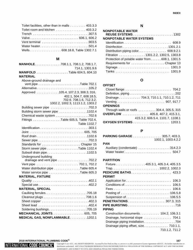
INDEX
2018 INTERNATIONAL PLUMBING CODE® 167
Toilet facilities, other than in malls . . . . . . . . . 403.3.3Toilet room and kitchen . . . . . . . . . . . . . . . . . 403.3.2Trench . . . . . . . . . . . . . . . . . . . . . . . . . . . . . . . .307.5Valve. . . . . . . . . . . . . . . . . . . . . . . . . . . . 606.1, 606.2Vent terminal . . . . . . . . . . . . . . . . . . . . . . . . . . .903.5Water heater . . . . . . . . . . . . . . . . . . . . . . . . . . . .501.4Wells . . . . . . . . . . . . . . . . . . 608.18.8, Table 1302.7.1
MMANHOLE. . . . . . . . . . . . . . .708.1.1, 708.1.2, 708.1.7,
714.1, 1301.9.6MANIFOLD . . . . . . . . . . . . . . . . . . Table 604.5, 604.10MATERIAL
Above-ground drainage and vent pipe . . . . . . . . . . . . . . . . . . . . . . . .Table 702.1
Alternative. . . . . . . . . . . . . . . . . . . . . . . . . . . . . .105.2Approved . . . . . . . . . . . . .105.4, 107.2.3, 308.3, 316,
402.1, 504.7, 608.18.5,702.6. 708.1.6, 712.3.2,
1002.2, 1002.3, 1113.1.2, 1303.2Building sewer pipe . . . . . . . . . . . . . . . . . . . . . .702.3Building storm sewer pipe . . . . . . . . . . . . . . . .1102.4Chemical waste system . . . . . . . . . . . . . . . . . . .702.6Fittings . . . . . . . . . . . . . . . .Table 605.5, Table 702.4,
Table 1102.7Identification . . . . . . . . . . . . . . . . . . . . . . . . . . . .303.1Joint . . . . . . . . . . . . . . . . . . . . . . . . . . . . . . . 605, 705Roof drain . . . . . . . . . . . . . . . . . . . . . . . . . . . . .1102.6Sewer pipe . . . . . . . . . . . . . . . . . . . . . . . . . . . . .702.3Standards for . . . . . . . . . . . . . . . . . . . . . . Chapter 15Storm sewer pipe . . . . . . . . . . . . . . . . . .Table 1102.4Subsoil drain pipe . . . . . . . . . . . . . . . . . . . . . . .1102.5Underground building
drainage and vent pipe . . . . . . . . . . . . . . . . . .702.2Vent pipe . . . . . . . . . . . . . . . . . . . . . . . . 702.1, 702.2Water distribution pipe . . . . . . . . . . . . . . .Table 605.4Water service pipe . . . . . . . . . . . . . . . . . .Table 605.3
MATERIAL, FIXTUREQuality . . . . . . . . . . . . . . . . . . . . . . . . . . . . . . . .402.1Special use . . . . . . . . . . . . . . . . . . . . . . . . . . . . .402.2
MATERIAL, SPECIALCaulking ferrules. . . . . . . . . . . . . . . . . . . . . . . .705.18Cleanout plugs . . . . . . . . . . . . . . . . . . . . . . . . 708.1.6Sheet copper . . . . . . . . . . . . . . . . . . . . . . . . . . .402.3Sheet lead . . . . . . . . . . . . . . . . . . . . . . . . . . . . .402.4Soldering bushings . . . . . . . . . . . . . . . . . . . . . .705.19
MECHANICAL JOINTS. . . . . . . . . . . . . . . . . . 605, 705MEDICAL GAS, NONFLAMMABLE . . . . . . . . . .1202.1
NNONPOTABLE WATER
REUSE SYSTEMS . . . . . . . . . . . . . . . . . . . . . . . 1302NONPOTABLE WATER SYSTEMS
Identification . . . . . . . . . . . . . . . . . . . . . . . . . . . 608.9Disinfection . . . . . . . . . . . . . . . . . . . . . . . . . . 1301.2.1Distribution piping color. . . . . . . . . . . . . . . . 608.9.2.1Filtration . . . . . . . . . . . . . . . 1301.2.2, 1302.5, 1303.8Protection of potable water from. . . . . . 608.1, 1301.5Requirements for . . . . . . . . . . . . . . . . . . . Chapter 13Signage. . . . . . . . . . . . . . . . . . . . . . . . . . . . . . 1301.3Tanks . . . . . . . . . . . . . . . . . . . . . . . . . . . . . . . 1301.9
OOFFSET
Closet flange. . . . . . . . . . . . . . . . . . . . . . . . . . . 704.2Definition, piping . . . . . . . . . . . . . . . . . . . . . . . . . . 202Drainage . . . . . . . . . . . . 704.3, 710.1.1, 710.1.2, 711Venting . . . . . . . . . . . . . . . . . . . . . . . . . . . 907, 917.7
OPENINGSThrough walls or roofs . . . . . . . . . . 304.4, 305.5, 315
OVERFLOW . . . . . . . . . . . . . . . 405.8, 407.2, 415.3.1,415.3.2, 606.5.4, 1101.7, 1108.1
OXYGEN SYSTEMS . . . . . . . . . . . . . . . . . . . . . 1203.1
PPARKING GARAGE . . . . . . . . . . . . . . . . 305.7, 403.3,
1002.1, 1003.4.2.2PAN
Auxiliary (condensate) . . . . . . . . . . . . . . . . . . 314.2.3Water heater . . . . . . . . . . . . . . . . . . . . . . . . . . . 504.7
PARTITIONFixture. . . . . . . . . . . . . . . . . 405.3.1, 405.3.4, 405.3.5Trap. . . . . . . . . . . . . . . . . . . . . . . . . . . 1002.2, 1002.3
PEDICURE BATHS . . . . . . . . . . . . . . . . . . . . . . . 423.3PERMIT
Application for . . . . . . . . . . . . . . . . . . . . . . . . . . 106.3Conditions of . . . . . . . . . . . . . . . . . . . . . . . . . . . 106.5Fees . . . . . . . . . . . . . . . . . . . . . . . . . . . . . . . . . 106.6Posting of . . . . . . . . . . . . . . . . . . . . . . . . . . . . 106.5.8Suspension of . . . . . . . . . . . . . . . . . . . . . . . . . 106.5.5
PENETRATIONS . . . . . . . . . . . . . . . . . . . . . 307.3, 315PIPE BURSTING . . . . . . . . . . . . . . . . . . . . . . . . . . . 716PIPING
Construction documents . . . . . . . . . . . 104.2, 106.3.1Drainage, horizontal slope . . . . . . . . . . . . . . . . 704.1Drainage piping installation. . . . . . . . . . . . . . . . . . 704Drainage piping offset, size. . . . . . . . . . . . . . 710.1.1,
710.1.2, 711.2
Copyright © 2017 ICC. ALL RIGHTS RESERVED. Accessed by Eric Fitch on May 15, 2018 8:17:14 AM pursuant to License Agreement with ICC. No further reproduction ordistribution authorized. ANY UNAUTHORIZED REPRODUCTION OR DISTRIBUTION IS A VIOLATION OF THE FEDERAL COPYRIGHT ACT AND THE LICENSEAGREEMENT, AND SUBJECT TO CIVIL AND CRIMINAL PENALTIES THEREUNDER.
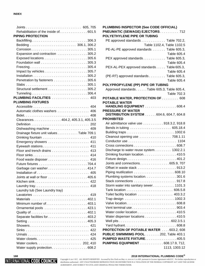
INDEX
168 2018 INTERNATIONAL PLUMBING CODE®
Joints . . . . . . . . . . . . . . . . . . . . . . . . . . . . . . 605, 705Rehabilitation of the inside of. . . . . . . . . . . . . . . 601.5
PIPING PROTECTIONBackfilling. . . . . . . . . . . . . . . . . . . . . . . . . . . . . . 306.3Bedding . . . . . . . . . . . . . . . . . . . . . . . . . 306.1, 306.2Corrosion . . . . . . . . . . . . . . . . . . . . . . . . . . . . . . 305.1Expansion and contraction . . . . . . . . . . . . . . . . 305.2Exposed locations . . . . . . . . . . . . . . . . . . . . . . . 305.6Foundation wall . . . . . . . . . . . . . . . . . . . . . . . . . 305.3Freezing. . . . . . . . . . . . . . . . . . . . . . . . . . . . . . . 305.4Impact by vehicles . . . . . . . . . . . . . . . . . . . . . . . 305.7Installation . . . . . . . . . . . . . . . . . . . . . . . . . . . . . 305.2Penetration by fasteners . . . . . . . . . . . . . . . . . . 305.6Slabs . . . . . . . . . . . . . . . . . . . . . . . . . . . . . . . . . 305.1Structural settlement . . . . . . . . . . . . . . . . . . . . . 305.2Tunneling . . . . . . . . . . . . . . . . . . . . . . . . . . . . . . 306.4
PLUMBING FACILITIES . . . . . . . . . . . . . . . . . . . . 403PLUMBING FIXTURES
Accessible . . . . . . . . . . . . . . . . . . . . . . . . . . . . . . 404Automatic clothes washers . . . . . . . . . . . . . . . . . 406Bidet. . . . . . . . . . . . . . . . . . . . . . . . . . . . . . . . . . . 408Clearances. . . . . . . . . . . . . . . 404.2, 405.3.1, 405.3.5Definition . . . . . . . . . . . . . . . . . . . . . . . . . . . . . . . 202Dishwashing machine . . . . . . . . . . . . . . . . . . . . . 409Drainage fixture unit values . . . . . . . . . . . Table 709.1Drinking fountain . . . . . . . . . . . . . . . . . . . . . . . . . 410Emergency showers . . . . . . . . . . . . . . . . . . . . . . 411Eyewash stations. . . . . . . . . . . . . . . . . . . . . . . . . 411Floor and trench drains . . . . . . . . . . . . . . . . . . . . 413Floor sinks . . . . . . . . . . . . . . . . . . . . . . . . . . . . . . 414Food waste disposer . . . . . . . . . . . . . . . . . . . . . . 416Future fixtures . . . . . . . . . . . . . . . . . . . . . . . . . . 704.4Garbage can washer . . . . . . . . . . . . . . . . . . . . . 414.7Installation of . . . . . . . . . . . . . . . . . . . . . . . . . . . . 405Joints at wall or floor . . . . . . . . . . . . . . . . . . . . . 405.6Kitchen sink . . . . . . . . . . . . . . . . . . . . . . . . . . . . . 422Laundry tray. . . . . . . . . . . . . . . . . . . . . . . . . . . . . 418Laundry tub (See Laundry tray)Lavatories . . . . . . . . . . . . . . . . . . . . . . . . . . . . . . 419Materials . . . . . . . . . . . . . . . . . . . . . . . . . . . . . . 402.1Minimum number of . . . . . . . . . . . . . . . . . . . . . . 403.1Ornamental pools . . . . . . . . . . . . . . . . . . . . . . . 423.1Quality of . . . . . . . . . . . . . . . . . . . . . . . . . . . . . . 402.1Separate facilities for . . . . . . . . . . . . . . . . . . . . . 403.2Setting . . . . . . . . . . . . . . . . . . . . . . . . . . . . . . . . 405.3Showers. . . . . . . . . . . . . . . . . . . . . . . . . . . . . . . . 421Sinks . . . . . . . . . . . . . . . . . . . . . . . . . . . . . . . . . . 422Urinals . . . . . . . . . . . . . . . . . . . . . . . . . . . . . . . . . 424Water closets . . . . . . . . . . . . . . . . . . . . . . . . . . . . 425Water coolers. . . . . . . . . . . . . . . . . . . . . . . . 202, 410Water supply protection . . . . . . . . . . . . . . . . . . . 608.2
PLUMBING INSPECTOR (See CODE OFFICIAL)PNEUMATIC (SEWAGE) EJECTORS . . . . . . . . . . 712POLYETHYLENE PIPE OR TUBING
PE approved standards . . . . . . . . . . . . . Table 702.2,Table 1102.4, Table 1102.5
PE-AL-PE approved standards . . . . . . . Table 605.3,Table 605.4
PEX approved standards . . . . . . . . . . . . Table 605.3,Table 605.4
PEX-AL-PEX approved standards . . . . . Table 605.3, Table 605.4
(PE-RT) approved standards . . . . . . . . . Table 605.3,Table 605.4
POLYPROPYLENE (PP) PIPE OR TUBINGApproved standards . . . . . . Table 605.3, Table 605.4,
Table 702.3POTABLE WATER, PROTECTION OF . . . . . . . . . 608POTABLE WATER
HANDLING EQUIPMENT . . . . . . . . . . . . . . . . . 608.4PRESSURE OF WATER
DISTRIBUTION SYSTEM . . . . . . 604.6, 604.7, 604.8PROHIBITED
Air admittance valve use . . . . . . . . . . . 918.3.2, 918.8Bends in tubing . . . . . . . . . . . . . . . . . . . . . . 605.18.4Building traps . . . . . . . . . . . . . . . . . . . . . . . . . . 1002.6Cleanout opening use . . . . . . . . . . . . . . . . . 708.1.11Conductor use . . . . . . . . . . . . . . . . . . . . . . . . . . 1104Cross connections . . . . . . . . . . . . . . . . . . . . . . . 608.7Discharge to water reuse system. . . . . . . . . 1302.2.1Drinking fountain location. . . . . . . . . . . . . . . . . . 410.5Fixture design. . . . . . . . . . . . . . . . . . . . . . . . . . . 401.2Joints and connections. . . . . . . . . . . . . . . . 605.9, 707Offset in waste stack . . . . . . . . . . . . . . . . . . . . . 913.2Piping reutilization . . . . . . . . . . . . . . . . . . . . . . 608.10Plumbing systems location. . . . . . . . . . . . . . . . . 301.6Stack connections . . . . . . . . . . . . . . . . . . . . . . . 917.8Storm water into sanitary sewer. . . . . . . . . . . . 1101.3Tank location . . . . . . . . . . . . . . . . . . . . . . . . . 606.5.8Toilet facility location . . . . . . . . . . . . . . . . . . . 403.3.2Trap design . . . . . . . . . . . . . . . . . . . . . . . . . . . 1002.3Valve location. . . . . . . . . . . . . . . . . . . . . . . . . . . 608.8Vent terminal use . . . . . . . . . . . . . . . . . . . . . . . . 903.4Water cooler location . . . . . . . . . . . . . . . . . . . . . 410.5Water dispenser locations . . . . . . . . . . . . . . . . . 410.5Well pits . . . . . . . . . . . . . . . . . . . . . . . . . . . . 602.3.5.1Yard hydrant. . . . . . . . . . . . . . . . . . . . . . . . . . . . 608.8
PROTECTION OF POTABLE WATER . . . . 603.2, 608PUBLIC SWIMMIMG POOL . . . . . . . . 202, Table 403.1PUMPED WASTE FIXTURE. . . . . . . . . . . . . . . . . 405.5PUMPING EQUIPMENT . . . . . . . . . . . . . 608.17.9, 712,
1113, 1303.12
Copyright © 2017 ICC. ALL RIGHTS RESERVED. Accessed by Eric Fitch on May 15, 2018 8:17:14 AM pursuant to License Agreement with ICC. No further reproduction ordistribution authorized. ANY UNAUTHORIZED REPRODUCTION OR DISTRIBUTION IS A VIOLATION OF THE FEDERAL COPYRIGHT ACT AND THE LICENSEAGREEMENT, AND SUBJECT TO CIVIL AND CRIMINAL PENALTIES THEREUNDER.
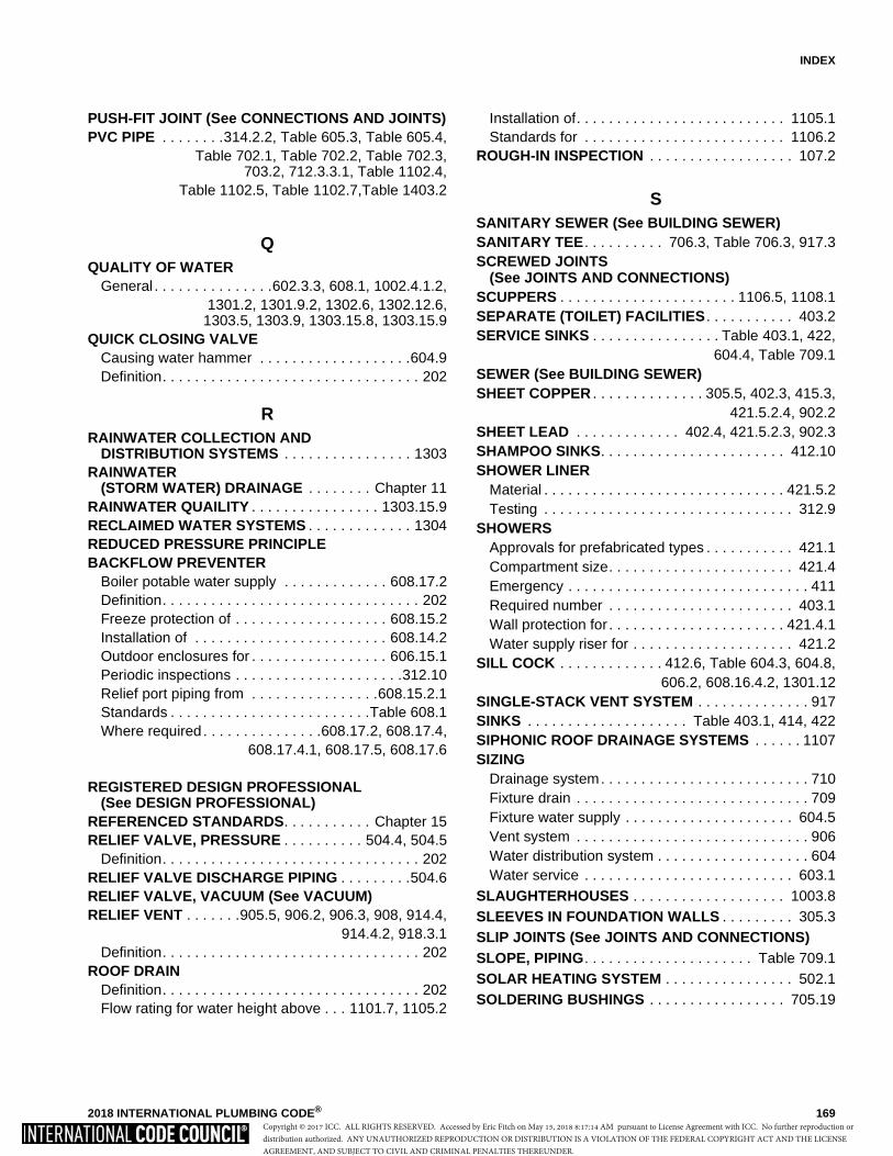
INDEX
2018 INTERNATIONAL PLUMBING CODE® 169
PUSH-FIT JOINT (See CONNECTIONS AND JOINTS)PVC PIPE . . . . . . . .314.2.2, Table 605.3, Table 605.4,
Table 702.1, Table 702.2, Table 702.3,703.2, 712.3.3.1, Table 1102.4,
Table 1102.5, Table 1102.7,Table 1403.2
QQUALITY OF WATER
General . . . . . . . . . . . . . . .602.3.3, 608.1, 1002.4.1.2,1301.2, 1301.9.2, 1302.6, 1302.12.6,
1303.5, 1303.9, 1303.15.8, 1303.15.9QUICK CLOSING VALVE
Causing water hammer . . . . . . . . . . . . . . . . . . .604.9Definition. . . . . . . . . . . . . . . . . . . . . . . . . . . . . . . . 202
RRAINWATER COLLECTION AND
DISTRIBUTION SYSTEMS . . . . . . . . . . . . . . . . 1303RAINWATER
(STORM WATER) DRAINAGE . . . . . . . . Chapter 11RAINWATER QUAILITY . . . . . . . . . . . . . . . . 1303.15.9RECLAIMED WATER SYSTEMS . . . . . . . . . . . . . 1304REDUCED PRESSURE PRINCIPLE BACKFLOW PREVENTER
Boiler potable water supply . . . . . . . . . . . . . 608.17.2Definition. . . . . . . . . . . . . . . . . . . . . . . . . . . . . . . . 202Freeze protection of . . . . . . . . . . . . . . . . . . . 608.15.2Installation of . . . . . . . . . . . . . . . . . . . . . . . . 608.14.2Outdoor enclosures for . . . . . . . . . . . . . . . . . 606.15.1Periodic inspections . . . . . . . . . . . . . . . . . . . . .312.10Relief port piping from . . . . . . . . . . . . . . . .608.15.2.1Standards . . . . . . . . . . . . . . . . . . . . . . . . .Table 608.1Where required. . . . . . . . . . . . . . .608.17.2, 608.17.4,
608.17.4.1, 608.17.5, 608.17.6
REGISTERED DESIGN PROFESSIONAL(See DESIGN PROFESSIONAL)
REFERENCED STANDARDS. . . . . . . . . . . Chapter 15RELIEF VALVE, PRESSURE . . . . . . . . . . 504.4, 504.5
Definition. . . . . . . . . . . . . . . . . . . . . . . . . . . . . . . . 202RELIEF VALVE DISCHARGE PIPING . . . . . . . . .504.6RELIEF VALVE, VACUUM (See VACUUM)RELIEF VENT . . . . . . .905.5, 906.2, 906.3, 908, 914.4,
914.4.2, 918.3.1Definition. . . . . . . . . . . . . . . . . . . . . . . . . . . . . . . . 202
ROOF DRAINDefinition. . . . . . . . . . . . . . . . . . . . . . . . . . . . . . . . 202Flow rating for water height above . . . 1101.7, 1105.2
Installation of. . . . . . . . . . . . . . . . . . . . . . . . . . 1105.1Standards for . . . . . . . . . . . . . . . . . . . . . . . . . 1106.2
ROUGH-IN INSPECTION . . . . . . . . . . . . . . . . . . 107.2
SSANITARY SEWER (See BUILDING SEWER)SANITARY TEE. . . . . . . . . . 706.3, Table 706.3, 917.3SCREWED JOINTS
(See JOINTS AND CONNECTIONS)SCUPPERS . . . . . . . . . . . . . . . . . . . . . . 1106.5, 1108.1SEPARATE (TOILET) FACILITIES . . . . . . . . . . . 403.2SERVICE SINKS . . . . . . . . . . . . . . . . Table 403.1, 422,
604.4, Table 709.1SEWER (See BUILDING SEWER)SHEET COPPER . . . . . . . . . . . . . . 305.5, 402.3, 415.3,
421.5.2.4, 902.2SHEET LEAD . . . . . . . . . . . . . 402.4, 421.5.2.3, 902.3SHAMPOO SINKS. . . . . . . . . . . . . . . . . . . . . . . 412.10SHOWER LINER
Material . . . . . . . . . . . . . . . . . . . . . . . . . . . . . . 421.5.2Testing . . . . . . . . . . . . . . . . . . . . . . . . . . . . . . . 312.9
SHOWERSApprovals for prefabricated types . . . . . . . . . . . 421.1Compartment size. . . . . . . . . . . . . . . . . . . . . . . 421.4Emergency . . . . . . . . . . . . . . . . . . . . . . . . . . . . . . 411Required number . . . . . . . . . . . . . . . . . . . . . . . 403.1Wall protection for . . . . . . . . . . . . . . . . . . . . . . 421.4.1Water supply riser for . . . . . . . . . . . . . . . . . . . . 421.2
SILL COCK . . . . . . . . . . . . . 412.6, Table 604.3, 604.8,606.2, 608.16.4.2, 1301.12
SINGLE-STACK VENT SYSTEM . . . . . . . . . . . . . . 917SINKS . . . . . . . . . . . . . . . . . . . . Table 403.1, 414, 422SIPHONIC ROOF DRAINAGE SYSTEMS . . . . . . 1107SIZING
Drainage system. . . . . . . . . . . . . . . . . . . . . . . . . . 710Fixture drain . . . . . . . . . . . . . . . . . . . . . . . . . . . . . 709Fixture water supply . . . . . . . . . . . . . . . . . . . . . 604.5Vent system . . . . . . . . . . . . . . . . . . . . . . . . . . . . . 906Water distribution system . . . . . . . . . . . . . . . . . . . 604Water service . . . . . . . . . . . . . . . . . . . . . . . . . . 603.1
SLAUGHTERHOUSES . . . . . . . . . . . . . . . . . . . 1003.8SLEEVES IN FOUNDATION WALLS . . . . . . . . . 305.3SLIP JOINTS (See JOINTS AND CONNECTIONS)SLOPE, PIPING. . . . . . . . . . . . . . . . . . . . . Table 709.1SOLAR HEATING SYSTEM . . . . . . . . . . . . . . . . 502.1SOLDERING BUSHINGS . . . . . . . . . . . . . . . . . 705.19
Copyright © 2017 ICC. ALL RIGHTS RESERVED. Accessed by Eric Fitch on May 15, 2018 8:17:14 AM pursuant to License Agreement with ICC. No further reproduction ordistribution authorized. ANY UNAUTHORIZED REPRODUCTION OR DISTRIBUTION IS A VIOLATION OF THE FEDERAL COPYRIGHT ACT AND THE LICENSEAGREEMENT, AND SUBJECT TO CIVIL AND CRIMINAL PENALTIES THEREUNDER.
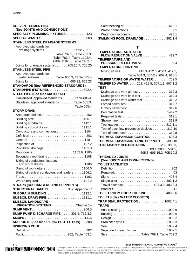
INDEX
170 2018 INTERNATIONAL PLUMBING CODE®
SOLVENT CEMENTING (See JOINTS AND CONNECTIONS)
SPECIALTY PLUMBING FIXTURES . . . . . . . . . . . 423SPECIAL WASTES . . . . . . . . . . . . . . . . . . . . . . . . 803STAINLESS STEEL DRAINAGE SYSTEMS
Approved standards for drainage systems . . . . . . . . . . . . . . . . Table 702.1,
Table 702.2, Table 702.3,Table 702.4, Table 1102.4,Table 1102.5, Table 1102.7
Joints for drainage systems . . . . . . . 705.16.7, 705.20STAINLESS STEEL PIPE
Approved standards for water systems . . . . . . . . Table 605.3, Table 605.4
Joints for . . . . . . . . . . . . . . . . . . . . . . 605.22, 605.23STANDARDS (See REFERENCED STANDARDS)STANDPIPE (FIXTURE). . . . . . . . . . . . . . . . . . . . 802.4STEEL PIPE (See also MATERIAL)
Galvanized, approved standards . . . . . . . Table 605.4 Stainless, approved standards . . . . . . . Table 605.3,
Table 605.4STORM DRAIN
Area drain definition. . . . . . . . . . . . . . . . . . . . . . . 202Building size. . . . . . . . . . . . . . . . . . . . . . . . . . . 1106.1Building subdrains . . . . . . . . . . . . . . . . . . . . . . 1112.1Building subsoil drains . . . . . . . . . . . . . . . . . . . 1111.1Conductors and connections . . . . . . . . . . . . . . . 1104Definition . . . . . . . . . . . . . . . . . . . . . . . . . . . . . . . 202General . . . . . . . . . . . . . . . . . . . . . . . . . . . . . . . 1101Inspection of . . . . . . . . . . . . . . . . . . . . . . . . . . . 107.2Prohibited drainage . . . . . . . . . . . . . . . . . . . . . 1101.3Roof drains . . . . . . . . . . . . . . . . . . . . . . 1102.6, 1105Secondary roof drains . . . . . . . . . . . . . . . . . . . . 1108Sizing of conductors, leaders
and storm drains. . . . . . . . . . . . . . . . . . . . . . . 1106Sizing of roof gutters . . . . . . . . . . . . . . . . . . . . 1106.6Sizing of vertical conductors and leaders . . . . 1106.2Traps . . . . . . . . . . . . . . . . . . . . . . . . . . . . . . . . . 1103Where required . . . . . . . . . . . . . . . . . . . . . . . . 1101.2
STRAPS (See HANGERS AND SUPPORTS)STRUCTURAL SAFETY . . . . . . . . . . 307, Appendix CSUBDRAIN BUILDING. . . . . . . . . . . . . . . . . . . . 1112.1SUBSOIL DRAIN PIPE. . . . . . . . . . . . . . . . . . . . 1111.1SUBSOIL LANDSCAPE
IRRIGATION SYSTEMS . . . . . . . . . . . . . .Chapter 14SUMP VENT . . . . . . . . . . . . . . . . . . . . . . . . . . . . . 906.5SUMP PUMP DISCHARGE PIPE. . . . . . 301.6, 712.3.3SUMPS . . . . . . . . . . . . . . . . . . . . . . . . . . . . . . . . . 1113SUPPORTS (See also PIPING PROTECTION). . . 308SWIMMING POOL
Definition . . . . . . . . . . . . . . . . . . . . . . . . . . . . . . . 202Public . . . . . . . . . . . . . . . . . . . . . . . . 202, Table 403.1
Solar heating of . . . . . . . . . . . . . . . . . . . . . . . . . 612.1Waste connections. . . . . . . . . . . . . . . . . . . . . . . . 801Water connections to . . . . . . . . . . . . . . . . . . . . . 423.1
SWIMMING POOL DRAINAGE . . . . . . . . . . . . 802.1.4
TTEMPERATURE-ACTUATED
FLOW REDUCTION VALVE . . . . . . . . . . . . . . . 412.7TEMPERATURE AND
PRESSURE RELIEF VALVE. . . . . . . . . . . . . . . . 504TEMPERATURE CONTROL
Mixing valves . . . . . . . . . . 411.3, 412.3, 412.4, 412.5,Table 604.3, 607.2.2, 607.4, 613.1
TEMPERATURE OF WASTE WATER . . . . . . . . . 702.5TEMPERED WATER . . . . 202, 419.5, 607.1.1, 607.1.2TEST
Drainage and vent air test . . . . . . . . . . . . . . . . . 312.3Drainage and vent final test . . . . . . . . . . . . . . . . 312.4Drainage and vent water test . . . . . . . . . . . . . . . 312.2Forced sewer test. . . . . . . . . . . . . . . . . . . . . . . . 312.7Gravity sewer test . . . . . . . . . . . . . . . . . . . . . . . 312.6Percolation test . . . . . . . . . . . . . . . . . . . . . . . . 1402.2Required tests . . . . . . . . . . . . . . . . . . . . . . . . . . 312.1Shower liner . . . . . . . . . . . . . . . . . . . . . . . . . . . . 312.9Test gauges . . . . . . . . . . . . . . . . . . . . . . . . . . 312.1.1Test of backflow prevention devices . . . . . . . . 312.10Test of conductors . . . . . . . . . . . . . . . . . . . . . . . 312.8
THERMAL EXPANSION CONTROL . . . . . . . . . . 607.3THERMAL EXPANSION TANK, SUPPORT . . . 308.10THIRD-PARTY CERTIFICATION . . . . . . . . 202, 303.3,
303.4, 303.5, 501.5,605.3, 605.15.2, 705.10.2
THREADED JOINTS(See JOINTS AND CONNECTIONS)
TOILET FACILITIES Definition . . . . . . . . . . . . . . . . . . . . . . . . . . . . . . . 202Required. . . . . . . . . . . . . . . . . . . . . . . . . . . . . . . . 403Signs . . . . . . . . . . . . . . . . . . . . . . . . . . . . . . . . . 403.4Single-user . . . . . . . . . . . . . . . . . . . . . . . . . . . 403.1.2Travel distance. . . . . . . . . . . . . . . . . 403.3.3, 403.3.4Workers’ . . . . . . . . . . . . . . . . . . . . . . . . . . . . . . . . 311
TOILET ROOM DOOR LOCKING . . . . . . . . . . 403.3.6TOILETS (See WATER CLOSETS)TRAP SEAL PROTECTION . . . . . . . . . . . . . . 1002.4.1TRAPS
Acid-resisting . . . . . . . . . . . . . . . . . . . . . . . . . . 1002.9Building . . . . . . . . . . . . . . . . . . . . . . . . . . . . . . 1002.6Design . . . . . . . . . . . . . . . . . . . . . . . . . . . . . . . 1002.2Prohibited types . . . . . . . . . . . . . . . . . . . . . . . . 1002.3Seal . . . . . . . . . . . . . . . . . . . . . . . . . . . . . . . . . 1002.4Separate for each fixture . . . . . . . . . . . . . . . . . 1002.1Size . . . . . . . . . . . . . . . . . . Table 709.1, Table 709.2
Copyright © 2017 ICC. ALL RIGHTS RESERVED. Accessed by Eric Fitch on May 15, 2018 8:17:14 AM pursuant to License Agreement with ICC. No further reproduction ordistribution authorized. ANY UNAUTHORIZED REPRODUCTION OR DISTRIBUTION IS A VIOLATION OF THE FEDERAL COPYRIGHT ACT AND THE LICENSEAGREEMENT, AND SUBJECT TO CIVIL AND CRIMINAL PENALTIES THEREUNDER.

INDEX
2018 INTERNATIONAL PLUMBING CODE® 171
TRENCH DRAINS . . . . . . . . . . . . . . . . . . . . . . . . . . 413TRENCHING, EXCAVATION AND BACKFILL . . . 306TUNNELING . . . . . . . . . . . . . . . . . . . . . . . . . . . . .306.4
UUNDERGROUND DRAINAGE
AND VENT PIPE . . . . . . . . . . . . . . . . . . . . . . . .702.2URINAL PARTITIONS. . . . . . . . . . . . . . . . . . . . 405.3.5URINALS . . . . . . . . . . . . . . . . . . . . . . .Table 403.1, 424
VVACUUM BREAKER . . . . . . . . . 202, 312.10.2, 412.8,
415.2, Table 608.1, 608.3.1,608.14.5, 608.14.6, 608.16.4,608.16.4.1, 608.16.4.2, 609.4
VACUUM RELIEF VALVE . . . . . . . . . . . . 504.1, 504.2VACUUM DRAINAGE SYSTEMS. . . . . . . . . . . . . . 715VACUUM SYSTEM, MEDICAL . . . . . . . . . . . . . .1202.1VALVE
Air admittance. . . . . . . . . . . . . . . . . . . . . . . . 202, 918Approved standards . . . . . . . . . . . Table 605.7, 714.2Backwater. . . . . . . . . . . . . . . . . . . . . . . . . . . 202, 714Full-open. . . . . . . . . . . . . . . . . . . . . . . . . . .202, 605.3Pressure reducing . . . . . . . . . . . . . . . . . . . . . . .604.8Relief . . . . . . . . . . . . . . . . . . . . . . . . . . . . .202, 504.4Stop and waste . . . . . . . . . . . . . . . . . . . . . . . . . .608.8Temperature-actuated flow
reduction . . . . . . . . . . . . . . . . . . . . . . . . . . . . .412.7Transfer valves . . . . . . . . . . . . . . . . . . . . . . . . . .412.8
VENTIndividual . . . . . . . . . . . . . . . . . . . . . . . . . . . . . . . 910Sizing . . . . . . . . . . . . . . . . . . . . . . . . . . . . . . . . . . 906
VENT, RELIEF. . . . . . . . . . . . . . . . . . . . . . . . . . . . . 908VENT STACK
Definition. . . . . . . . . . . . . . . . . . . . . . . . . . . . . . . . 202Required . . . . . . . . . . . . . . . . . . . . . . . . . . . . . . .904.2
VENTS AND VENTINGBranch vents. . . . . . . . . . . . . . . . . . . . . . . . . . . .906.4Circuit . . . . . . . . . . . . . . . . . . . . . . . . . . . . . . . . . . 914Combination waste . . . . . . . . . . . . . . . . . . . . . . . . 915Common . . . . . . . . . . . . . . . . . . . . . . . . . . . . . . . . 911Definition. . . . . . . . . . . . . . . . . . . . . . . . . . . . . . . . 202Distance from trap . . . . . . . . . . . . Table 909.1, 909.2Engineered systems . . . . . . . . . . . . . . . . . . . . . . . 919Island fixture . . . . . . . . . . . . . . . . . . . . . . . . . . . . . 916Required vent . . . . . . . . . . . . . . . . . . . . . . . . . . .904.1Single stack . . . . . . . . . . . . . . . . . . . . . . . . . . . . . 917Vent stack. . . . . . . . . . . . . . . . . . . . . . . . . . . . . .904.2Vent terminal . . . . . . . . . . . . . . . . . . . . . . . . . . . . 903Waste stack . . . . . . . . . . . . . . . . . . . . . . . . . . . . . 913Wet vent . . . . . . . . . . . . . . . . . . . . . . . . . . . . . . . . 912
WWALL-HUNG WATER CLOSET . . . . . . . . . . . . . . . 425WASHING MACHINE
(See AUTOMATIC CLOTHES WASHER and DISHWASHER)
WASTEIndirect . . . . . . . . . . . . . . . . . . . . . . . . . . . . . . . . . 802Special . . . . . . . . . . . . . . . . . . . . . . . . . . . . . . . . . 803
WASTE RECEPTORSDefinition . . . . . . . . . . . . . . . . . . . . . . . . . . . . . . . . 202
WASTE STACK. . . . . . . . . . . . . . . . . . . . . . . . . . . . 913WASTE WATER TEMPERATURE . . . . . . . . . . . 702.5WATER
Cross connection . . . . . . . . . . . . . . . . . . . . . . . 608.7Distribution system design . . . . . . . . . . . . . . . . . . 604Distribution piping material . . . . . . . . . . . Table 605.4Excessive pressure. . . . . . . . . . . . . . . . . . . . . . 604.8Hammer . . . . . . . . . . . . . . . . . . . . . . . . . . . . . . 604.9Pressure booster. . . . . . . . . . . . . . . . . . . . . . . . 606.5Rain. . . . . . . . . . . . . . . . . . . . . . . . . . . . . . . . . . . . 202Reclaimed. . . . . . . . . . . . . . . . . . . . . . . . . . . . . . . 202 Service . . . . . . . . . . . . . . . . . . . . . . . . . . . . . . . . . 603Service piping material . . . . . . . . . . . . . . Table 605.3Storm . . . . . . . . . . . . . . . . . . . . . . . . . . . . . . . . . . 202
WATER CLOSETS . . . . . . . . . . . . . . . . . . . . . . . . . 425WATER CLOSET COMPARTMENTS. . . . . . . . 405.3.4WATER CLOSET PERSONAL
HYGIENE DEVICE . . . . . . . . . . . . . . . . . . . . . . 412.9WATER CONSERVATION
Fixtures . . . . . . . . . . . . . . . . . . . . . . . . . . . . . . . 604.4Flow rates . . . . . . . . . . . . . . . . . . . . . . . . Table 604.4
WATER COOLERApprovals . . . . . . . . . . . . . . . . . . . . . . . . . . . . . 410.1Definition . . . . . . . . . . . . . . . . . . . . . . . . . . . . . . . . 202Prohibited location . . . . . . . . . . . . . . . . . . . . . . 410.5
WATER DISPENSERDefinition . . . . . . . . . . . . . . . . . . . . . . . . . . . . . . . . 202Prohibited location . . . . . . . . . . . . . . . . . . . . . . 410.5Substitution for drinking fountain. . . . . . . . . . . . 410.4
WATER HAMMER . . . . . . . . . . . . . . . . . . . . . . . . 604.9WATER HEATER
Definition . . . . . . . . . . . . . . . . . . . . . . . . . . . . . . . . 202Requirements for . . . . . . . . . . . . . . . . . . . . Chapter 5
WATER HEATER PAN . . . . . . . . . . . . . . . . . . . . 504.7WATER TREATMENT
Drinking water systems. . . . . . . . . . . . . . . . . . . . . 611Softeners. . . . . . . . . . . . . . . . . . . . . . . . . . . . . . 608.4
WELL WATER. . . . . . . . . . . . . . . . . . . . . . . . . . 602.3.1WET VENT. . . . . . . . . . . . . . . . . . . . . . . . . . . . . . . . 912WIPED JOINTS . . . . . . . . . . . . . . . . . . . . . . . . . 705.9.2WORKERS’ TOILET FACILITIES . . . . . . . . . . . . . . 311
Copyright © 2017 ICC. ALL RIGHTS RESERVED. Accessed by Eric Fitch on May 15, 2018 8:17:14 AM pursuant to License Agreement with ICC. No further reproduction ordistribution authorized. ANY UNAUTHORIZED REPRODUCTION OR DISTRIBUTION IS A VIOLATION OF THE FEDERAL COPYRIGHT ACT AND THE LICENSEAGREEMENT, AND SUBJECT TO CIVIL AND CRIMINAL PENALTIES THEREUNDER.

172 2018 INTERNATIONAL PLUMBING CODE®
Copyright © 2017 ICC. ALL RIGHTS RESERVED. Accessed by Eric Fitch on May 15, 2018 8:17:14 AM pursuant to License Agreement with ICC. No further reproduction ordistribution authorized. ANY UNAUTHORIZED REPRODUCTION OR DISTRIBUTION IS A VIOLATION OF THE FEDERAL COPYRIGHT ACT AND THE LICENSEAGREEMENT, AND SUBJECT TO CIVIL AND CRIMINAL PENALTIES THEREUNDER.

People Helping People Build a Safer World®
* Some restrictions apply. Speak with an ICC Member Services Representative for details.
16-12897
BENEFITS THAT WORK FOR YOUNo matter where you are in your building career, put the benefits of ICC Membership to work for you!Membership in ICC connects you to exclusive I-Codes resources, continuing education opportunities and Members-Only benefits that include:
· Free code opinions from I-Codes experts
· Free I-Code book(s) or download to new Members*
· Discounts on I-Code resources, training and certification renewal
· Posting resumes and job search openings through the ICC Career Center
· Mentoring programs and valuable networking opportunities at ICC events
· Free benefits — Corporate and Governmental Members: Your staff can receive free ICC benefits too*
· Savings of up to 25% on code books and training materials and more
Put the benefits of ICC Membership to work for you and your career. Visit www.iccsafe.org/mem3 to join now or to renew your Membership. Or call 1-888-ICC-SAFE (422-7233), ext. 33804 to learn more today!
Copyright © 2017 ICC. ALL RIGHTS RESERVED. Accessed by Eric Fitch on May 15, 2018 8:17:14 AM pursuant to License Agreement with ICC. No further reproduction ordistribution authorized. ANY UNAUTHORIZED REPRODUCTION OR DISTRIBUTION IS A VIOLATION OF THE FEDERAL COPYRIGHT ACT AND THE LICENSEAGREEMENT, AND SUBJECT TO CIVIL AND CRIMINAL PENALTIES THEREUNDER.

17-14094
Look no further than ICC-ES PMG® The Leading provider of product evaluations in plumbing, mechanical and fuel gas, with excellent customer service and the highest acceptability by code officials at the price you’re looking for.
Benefits of having an ICC-ES PMG Listing · ICC-ES PMG offers a lower cost for
certification than competitors · Expedited certification for all client
listings · ICC-ES PMG does not conduct
warehouse inspections · ICC-ES PMG does not charge for
additional company listings
· ICC-ES will accept test reports from other entities
· No fee for EPA WaterSense listings and lead law listings
· No separate file for NSF 61 listings · ANSI and SCC Accredited
PMGC
ICC®
www.icc-es-pmg.org 800-423-6587 x7643
Copyright © 2017 ICC. ALL RIGHTS RESERVED. Accessed by Eric Fitch on May 15, 2018 8:17:14 AM pursuant to License Agreement with ICC. No further reproduction ordistribution authorized. ANY UNAUTHORIZED REPRODUCTION OR DISTRIBUTION IS A VIOLATION OF THE FEDERAL COPYRIGHT ACT AND THE LICENSEAGREEMENT, AND SUBJECT TO CIVIL AND CRIMINAL PENALTIES THEREUNDER.

People Helping People Build a Safer World®
17-14099
Looking for the missing piece?Solve the puzzle and advance your career with ICC UniversityICC University has been built from the ground up with you in mind.Take advantage of tools to help you better track and manage your career growth and professional development, including automatic CEU tracking and simplified search options to find code training. Plan for your future and manage your professional development from one, easy-to-use location.
ICC University provides you with:
• Simplified access to over 300 training options
• Automatic CEU tracking to keep you on track for recertification
• Robust curriculums that identify supporting courses, publications and exam study materials to assist you in preparing for certification exams and achieving your next professional milestone
• The ability to purchase all courses, related publications and exam preparation materials – as well as register for certification exams – from a single screen
• And more!
www.iccsafe.org/ExploreICCU
Copyright © 2017 ICC. ALL RIGHTS RESERVED. Accessed by Eric Fitch on May 15, 2018 8:17:14 AM pursuant to License Agreement with ICC. No further reproduction ordistribution authorized. ANY UNAUTHORIZED REPRODUCTION OR DISTRIBUTION IS A VIOLATION OF THE FEDERAL COPYRIGHT ACT AND THE LICENSEAGREEMENT, AND SUBJECT TO CIVIL AND CRIMINAL PENALTIES THEREUNDER.

Copyright © 2017 ICC. ALL RIGHTS RESERVED. Accessed by Eric Fitch on May 15, 2018 8:17:14 AM pursuant to License Agreement withICC. No further reproduction or distribution authorized. ANY UNAUTHORIZED REPRODUCTION OR DISTRIBUTION IS A VIOLATIONOF THE FEDERAL COPYRIGHT ACT AND THE LICENSE AGREEMENT, AND SUBJECT TO CIVIL AND CRIMINAL PENALTIESTHEREUNDER.