2018 Eagle Safety, Operation & Maintenance Manual
60
4420788 11/2017 2754KW 3160KW 2754KOE 2760KW 3160KOE 3566KW 3366KOE 3572KW 3372KOE 2760KOE 2018 Eagle Safety, Operation & Maintenance Manual
Transcript of 2018 Eagle Safety, Operation & Maintenance Manual

4420788 11/2017
2754KW 3160KW
2754KOE2760KW
3160KOE
3566KW
3366KOE
3572KW
3372KOE
2760KOE
2018 Eagle Safety, Operation & Maintenance Manual
1 CONTENTS
Litho In U.S.A. 11-2017
Contents
Introduction1.1 Important .............................................................................11.2 Product Identification...........................................................21.3 Serial Numbers ...................................................................21.4 Guidelines for the Disposal of Scrap Products....................3
Safety2.1 How to Operate Safely ........................................................4
Specifications3.1 Engine Specifications..........................................................93.2 Dimensions and Weights ..................................................113.3 Mower Specification..........................................................133.4 Cutting Unit Specification..................................................133.5 Belt Specification...............................................................133.6 Recommended Lubricants ................................................143.7 Accessories.......................................................................153.8 Support Literature .............................................................16
Decals4.1 Safety Decals....................................................................174.2 Instruction Decals..............................................................18
Controls5.1 Mower Controls .................................................................205.2 Control Panel ....................................................................215.3 Parking Brake....................................................................265.4 Steering Control Levers ....................................................265.5 Cutting Unit HOC Pedal ....................................................265.6 Lift Stop PEDAL ................................................................275.7 Operator Controlled Discharge DEFLECTOR...................27
Operation6.1 Daily Inspection.................................................................286.2 Interlock System................................................................296.3 Operating Procedure.........................................................306.4 Starting The Engine ..........................................................316.5 To Stop The Engine ..........................................................316.6 Driving...............................................................................326.7 Height of Cut .....................................................................336.8 Mowing..............................................................................336.9 Mowing On Slopes............................................................346.10 Towing The Mower..........................................................36
Maintenance and Lubrication Charts7.1 Maintenance Chart............................................................377.2 Lubrication Chart...............................................................387.3 Fluid Requirements...........................................................38
Maintenance8.1 General Precautions .........................................................398.2 Engine...............................................................................398.3 Engine Oil .........................................................................408.4 Engine Air Filter ................................................................418.5 Engine Exhaust.................................................................428.6 Fuel ...................................................................................428.7 Tires ..................................................................................438.8 Wheel Mounting Procedure ..............................................438.9 Charge the battery ............................................................438.10 Battery.............................................................................448.11 Drive Axle Fluid...............................................................458.12 Folding ROPS .................................................................468.13 Air Cooling System .........................................................478.14 Inspecting Blades............................................................478.15 Sharpening Blades..........................................................488.16 Electrical System ............................................................488.17 Belts ................................................................................498.18 Care and Cleaning ..........................................................508.19 Mower Storage................................................................51
Adjustments9.1 General Precautions .........................................................529.2 Forward Speed Limit Screws ............................................529.3 Torque Specification .........................................................53
Problem Solving10.1 General ...........................................................................5410.2 Eagle HP Model Fault Codes..........................................55
© 2017, Dixie Chopper, A Textron Company/Textron Innovations Inc. “All rights reserved, including the right to reproduce this
material or portions thereof in any form.”
Proposition 65 Warning
This product contains or releasechemicals known to the State ofCalifornia to cause cancer and birthdefects or other reproductive harm.


1 INTRODUCTION
en-1
1Introduction
1.1 IMPORTANT______________________________________________________________
The Dixie Chopper Eagle 2754KW, 2760KW, 2754KOE, 2760KOE and the Eagle HP 3160KW, 3566KW, 3572KW, 3160KOE,3366KOE, 3372KOE with a Gasoline engine is a self propelled rotary mower.
If you follow all instructions in this manual, you increase the life of your mower and keep its maximum performance.Adjustments and maintenance must always be done by an approved technician.
IMPORTANT: Do the maintenance included in this manual to make sure that the quality of cut is kept at a high level.
This SAFETY, OPERATION AND MAINTENANCE MANUAL is part of the mower and must stay with the mower always.Suppliers of both original and used mowers need to keep the documentation that comes with the mower.
You must use the mower to cut the grass and not for any other purpose. Compliance with the conditions or operation, serviceand repair specified by the manufacturer, are understood to be part of the correct use.
ALL operators MUST read through this manual and understand the Safety Instructions, controls, lubrication and maintenanceprocedures.
Make sure that you obey all safety and road traffic regulations.
You must not make any changes to the mower that the manufacturer does not approve. This type of change can release themanufacturer from the liability for any damage or injury.
When you discard worn parts, know the environmental result and use the systems available in the country where the moweris used. When the mower is at its end of life, there are guidelines in this manual for the removal of the mower from use.
Use only Dixie Chopper approved parts.
2006/42/ECThe instructions recorded here are the original instructions confirmed by Dixie Chopper, A Textron Company.
INTRODUCTION 1
en-2
1.2 PRODUCT IDENTIFICATION _________________________________________________
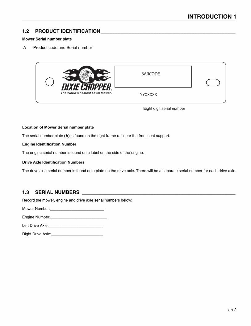
Mower Serial number plate
A Product code and Serial number
Location of Mower Serial number plate
The serial number plate (A) is found on the right frame rail near the front seat support.
Engine Identification Number
The engine serial number is found on a label on the side of the engine.
Drive Axle Identification Numbers
The drive axle serial number is found on a plate on the drive axle. There will be a separate serial number for each drive axle.
1.3 SERIAL NUMBERS ________________________________________________________
Record the mower, engine and drive axle serial numbers below:
Mower Number:_________________________
Engine Number:__________________________
Left Drive Axle:_________________________
Right Drive Axle:________________________
YYXXXXX
BARCODE
Eight digit serial number
1 INTRODUCTION
en-3
1.4 GUIDELINES FOR THE DISPOSAL OF SCRAP PRODUCTS _______________________
1.4.1 DURING SERVICE LIFE ____________________________________________________
The used oil and oil filters are hazardous materials. Follow the recommended procedures for their safe removal.
If a fluid leaks, contain the spill to make sure that the leak does not flow into the ground or drainage system. Follow the locallaws to make sure that leaks are controlled safely.
The maintenance procedures in this manual make sure that the damage that the mower can cause in the local environment iscontrolled safely.
Take these actions after the mower has completed its full service life.
1.4.2 END OF SERVICE LIFE _____________________________________________________
Use these guidelines with applicable Health, Safety and Environmental laws. Always use the approved local waste disposaland agencies for recycled materials.
• Park the mower in a location to use all of the necessary lifting equipment.• Use the correct tools and Personal Protective Equipment (PPE) and take instruction from the technical manuals
applicable to the mower.• Remove and keep correctly
1. Batteries2. Fuel3. Engine coolant4. Oils
• Disassemble the structure of the mower and refer to the technical manuals. Give attention to parts that havemechanical pressure or tension applied to the part in the mower, including springs.
• Separate items that continue to have service life and returned to storage.• Separate items that are worn into the material groups and removed according to the agencies for the recycled
materials that are available. Common types are as shown:• Steel• Non ferrous metals
• Aluminum• Brass• Copper
• Plastic Materials• Identified• Can be recycled• Can not be recycled• Not Identified
• Rubber• Electrical and Electronic Components
• Add items that can not be easily separated into different materials to the “General discarded materials” area.• Do not burn the discarded materialsChange the mower records to show that the mower is not in service and is discarded. Supply this serial number to DixieChopper Warranty Department to close their records.
SAFETY 2
en-4
2Safety
2.1 HOW TO OPERATE SAFELY ______________________________________________________
2.1.1 SAFE OPERATION
a Read the Operator’s Manual and other training material. If the operator or technician can not read this manual, theowner is responsible to describe this material to the operators and technicians.
a Read all of the instructions for this mower carefully. Know the controls and the correct operation of the equipment. b Children or persons who do not understand these instructions must not use the mower. The local regulations can limit
the age of the operator. c Never use a mower near persons, including children or animals. d Remember that the operator or owner is responsible for accidents or hazards that occur to other persons or their
property. e Never carry passengers. f Never allow persons to operate or service the mower or its attachments without correct instructions. g Do not operate equipment while tired, sick or after you use alcohol or drugs.
2.1.2 PREPARATION
a When you operate the mower, wear correct clothing, slip resistant work shoes or boots, work gloves, hard hat, safetyglasses and hearing protection. Long hair, loose clothing or jewelry can be caught in moving parts.
b Do not operate the equipment with the Interlock System disconnected or if the system does not operate correctly. Donot disconnect or prevent the operation of any switch.
c Never operate equipment that is not in correct order or without decals, guards, shields, deflectors or other protectivedevices fastened.
d Inspect the mower before you operate the mower. Check the tire pressure, the engine oil level, and the fuel level. Fuelis flammable. Use caution when you add the fuel to the mower.
e Operate the mower in daylight or in good artificial light. Use caution when you operate the mower during bad weather.Never operate the mower with lightning in the area.
f Inspect the area to select the accessories and attachments that are needed to correctly and safely do the job. Only useparts, accessories and attachments approved by Dixie Chopper.
g Be careful of holes in the terrain and other hazards that are not visible. h Inspect the area where the equipment is operated. Remove all objects you can find before you operate. Be careful of
obstructions above the ground (low tree limbs, electrical wires) and also underground obstacles (sprinklers, pipes, treeroots). Enter a new area carefully. Look for possible hazards.
i Inspect the cutting system before you start the mower. Make sure the blades are free to rotate. When you rotate oneblade, other blades can rotate.
2.1.3 OPERATION
a Never operate the engine without enough ventilation or in an enclosed area. The carbon monoxide in the exhaustfumes can increase to dangerous levels.
b Never carry passengers. Keep other persons or animals away from the mower. c Disengage all drives and engage the parking brake before you start the engine. Only start the engine with the operator
in the seat. Never start the engine with persons near the mower. d Keep your legs, arms and body inside the operator compartment while the mower is in operation. Keep your hands and
feet away from the cutting units. e Do not use on the slopes greater than the safe slope limit for the equipment. f To guard against over turning or loss of control:
WARNINGEQUIPMENT OPERATED INCORRECTLY OR WITHOUT TRAINING CAN BE DANGEROUS.
Know the location and correct operation of controls. Operators without experience must receive instruction fromanother person that knows the correct operation of the equipment before you operate the mower.
Only use parts, accessories and attachments approved by Dixie Chopper.
!
2 SAFETY
en-5
– Operate the mower up and down on the face of slopes (vertically), but not across the face (horizontally).
– Do not start or stop suddenly on slopes.
– Decrease the speed when you operate on slopes or when you must turn. Use caution when you changedirection. Turf condition can change the mower stability.
– Use caution when you operate the mower near drop-offs, ditches or embankments.
– Be careful of holes in the terrain and other hazards that are not visible.
g When you drive in the reverse direction, look behind you and down to make sure the path is clear. Do not operate thecutting unit when you drive in the reverse direction.
h Use caution when you go near corners, trees or other objects that can prevent a clear view. i Equipment must meet the current regulations to be driven on the public roads. j Before you move across or operate on the paths or roads, turn off the PTO switch, lift the cutting unit and travel at
decreased speed. Look for traffic. k Stop the blades when the mower is on any surface that is not grass. l Do not release the cut grass in the direction of persons or allow persons near the mower while in operation. m Do not operate the mower with damaged guards or without safety devices in position. n Do not change the engine governor setting or over-speed the engine. Never change or tamper with adjusters that are
closed with a seal for the engine speed control. o Before you leave the operator compartment, for any reason: – Disengage all the drives and lower the cutting unit to the ground.
– Engage the parking brake.
– Stop the engine and remove the key.
p When you hit an object or mower starts to cause the vibration that is not normal, inspect the mower for damage andmake repairs.
q Decrease the throttle setting before you stop the engine. r Do not use this equipment for uses that the mower was not made for.

SAFETY 2
en-6
2.1.4 ROPS
a The ROPS is a safety device. Keep the ROPS in the vertical and locked position. Always use the seat belt when youoperate the mower. Make sure the seat belt can be released quickly in an emergency.
b Only operate the mower with the ROPS in the folded position on flat and level surfaces when necessary. Do notoperate the mower with the ROPS in the folded position on slopes, near sharp edges or near water. There is no rollover protection with the ROPS in the folded position.
c Check for clearance before you drive below objects. Do not contact tree branches, electrical wires or other objects withthe ROPS.
d Do not use the seat belt with the ROPS in the folded position. e Inspect the ROPS for damage. Keep the ROPS hardware fastened. f Do not weld, drill, change or bend the ROPS. Replace a damaged ROPS. Do not try to correct a damaged ROPS. g Do not remove the ROPS from the mower. h Dixie Chopper must approve any changes to the ROPS.
2.1.5 SAFE HANDLING OF FUELS
a The fuel and the fuel vapors are flammable. Use caution when you add the fuel to the mower. The fuel vapors cancause an explosion.
b Never use the containers that are not approved to keep or transfer fuel. c Never keep the mower or fuel containers near an open flame or any device that can cause the ignition of fuel or fuel
vapors. d Never fill the fuel containers inside a vehicle or on a truck or trailer with a plastic liner. Always put the fuel container on
the ground away from your vehicle before you fill the container. e Refuel the mower before you start the engine. When the engine is in operation or while the engine is hot, never remove
the fuel cap or add fuel to the mower. f Refuel outdoors only and do not smoke when you add fuel. Extinguish all types of ignition. g The fuel nozzle must touch the rim of the fuel tank when you add fuel to the mower. Do not use a device to lock the fuel
nozzle in the open position. h Do not over fill the fuel tank. Leave at least 1 inch (2.5 cm) below the filler neck. i Always tighten the fuel tank cap and container cap after you add fuel. j If the fuel spills on your clothing, change your clothing immediately.
2.1.6 MAINTENANCE AND STORAGE
a Before you clean, adjust or repair this equipment, push PTO switch to the OFF position, lower the cutting unit to theground, engage the parking brake, stop the engine and remove the key.
b Make sure the mower is parked on a solid and level surface. c Never work on a mower that is lifted only by the jack. Always use the jack stands. d Never allow persons to service the mower or its attachments without correct instructions. e When the mower is parked, put into storage or left without an operator, lower the cutting device unless a positive
mechanical lock is used. f When you put the mower on a trailer or put the mower in storage, close the fuel valve. Do not keep fuel near flames or
drain the fuel inside a building. g Disconnect the battery before you service the mower. Always disconnect the negative battery cable before the positive
battery cable. Always connect the positive battery cable before the negative battery cable. h Charge the battery in an area with good airflow. The battery can release hydrogen gas that is explosive. To prevent an
explosion, keep any device that can cause sparks or flames away from the battery. i Disconnect the battery charger from the power supply before you connect or disconnect the battery charger to the
battery. Wear protective clothing and use insulated tools when you service the battery. j Be careful and wear gloves when you check or service the cutting unit blades. Replace any damaged blades, do not try
to correct a damaged blade. k Keep your hands and feet away from parts that move. Do not adjust the mower with the engine in operation, unless the
adjustment needs the engine in operation. l Carefully release the pressure from components with stored energy.
2 SAFETY
en-7
m To prevent injury from the hot, high pressure oil, never use your hands to check for oil leaks. Use the paper orcardboard to find leaks.
n The drive axle fluid pressure can have enough force to enter your skin. If drive axle fluid has entered your skin, a doctormust remove the drive axle fluid surgically within a few hours or gangrene can occur.
o Make sure the drive axle system is in good condition before you start the engine. p Keep the mower and the engine clean. q Allow the engine to become cool before storage and always remove the ignition key. r Keep all nuts, bolts and screws tight to make sure the equipment is in safe condition. s Replace worn or damaged parts for safety. Replace damaged or worn decals. Only use parts, accessories and
attachments approved by Dixie Chopper. t To decrease the fire hazard, remove materials that burn from the engine, muffler, battery tray and fuel tank area. u Disconnect the battery and controller connectors before you weld on this mower.
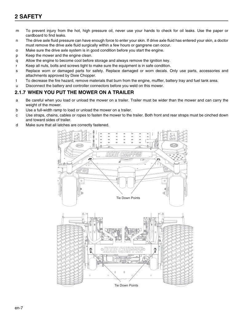
2.1.7 WHEN YOU PUT THE MOWER ON A TRAILER
a Be careful when you load or unload the mower on a trailer. Trailer must be wider than the mower and can carry theweight of the mower.
b Use a full-width ramp to load or unload the mower on a trailer. c Use straps, chains, cables or ropes to fasten the mower to the trailer. Both front and rear straps must be cinched down
and toward sides of trailer. d Make sure that all latches are correctly fastened.
Tie Down Points
Tie Down Points
SAFETY 2
en-8
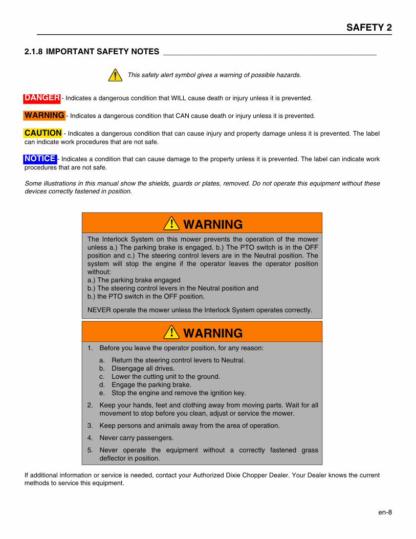
2.1.8 IMPORTANT SAFETY NOTES _______________________________________________
This safety alert symbol gives a warning of possible hazards.
DANGER - Indicates a dangerous condition that WILL cause death or injury unless it is prevented.
WARNING - Indicates a dangerous condition that CAN cause death or injury unless it is prevented.
CAUTION - Indicates a dangerous condition that can cause injury and property damage unless it is prevented. The labelcan indicate work procedures that are not safe.
NOTICE - Indicates a condition that can cause damage to the property unless it is prevented. The label can indicate workprocedures that are not safe.
Some illustrations in this manual show the shields, guards or plates, removed. Do not operate this equipment without thesedevices correctly fastened in position.
If additional information or service is needed, contact your Authorized Dixie Chopper Dealer. Your Dealer knows the currentmethods to service this equipment.
WARNINGThe Interlock System on this mower prevents the operation of the mowerunless a.) The parking brake is engaged. b.) The PTO switch is in the OFFposition and c.) The steering control levers are in the Neutral position. Thesystem will stop the engine if the operator leaves the operator positionwithout:a.) The parking brake engagedb.) The steering control levers in the Neutral position andb.) the PTO switch in the OFF position.
NEVER operate the mower unless the Interlock System operates correctly.
WARNING1. Before you leave the operator position, for any reason:
a. Return the steering control levers to Neutral.b. Disengage all drives.c. Lower the cutting unit to the ground.d. Engage the parking brake.e. Stop the engine and remove the ignition key.
2. Keep your hands, feet and clothing away from moving parts. Wait for allmovement to stop before you clean, adjust or service the mower.
3. Keep persons and animals away from the area of operation.
4. Never carry passengers.
5. Never operate the equipment without a correctly fastened grassdeflector in position.
!
!
3 SPECIFICATIONS
en-9
3Specifications
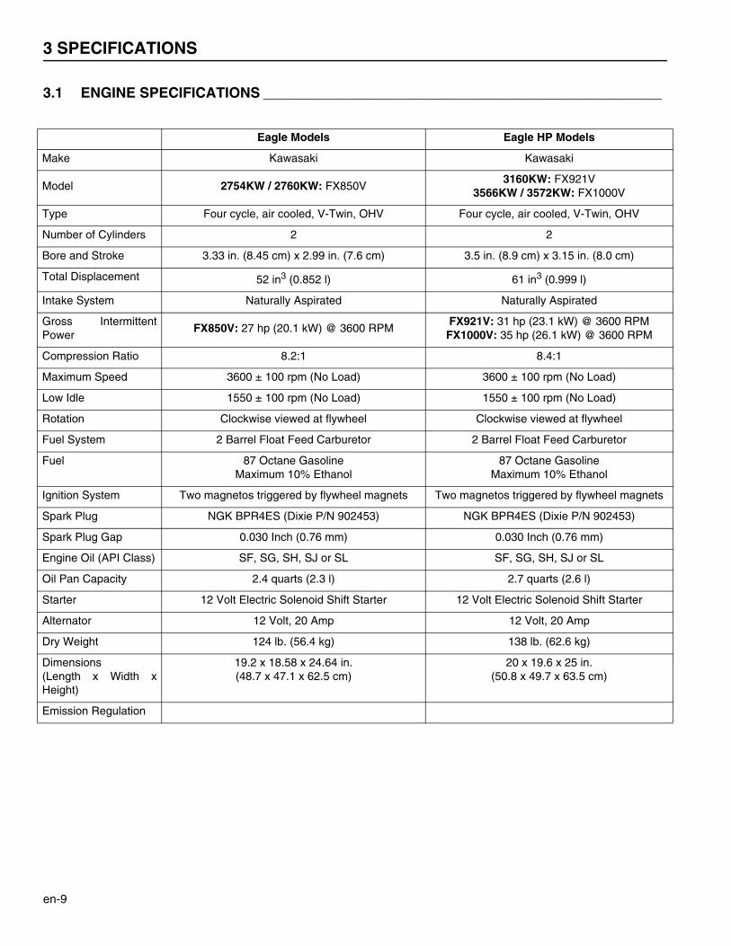
3.1 ENGINE SPECIFICATIONS __________________________________________________
Eagle Models Eagle HP Models
Make Kawasaki Kawasaki
Model 2754KW / 2760KW: FX850V3160KW: FX921V
3566KW / 3572KW: FX1000V
Type Four cycle, air cooled, V-Twin, OHV Four cycle, air cooled, V-Twin, OHV
Number of Cylinders 2 2
Bore and Stroke 3.33 in. (8.45 cm) x 2.99 in. (7.6 cm) 3.5 in. (8.9 cm) x 3.15 in. (8.0 cm)
Total Displacement 52 in3 (0.852 l) 61 in3 (0.999 l)
Intake System Naturally Aspirated Naturally Aspirated
Gross IntermittentPower
FX850V: 27 hp (20.1 kW) @ 3600 RPMFX921V: 31 hp (23.1 kW) @ 3600 RPM
FX1000V: 35 hp (26.1 kW) @ 3600 RPM
Compression Ratio 8.2:1 8.4:1
Maximum Speed 3600 ± 100 rpm (No Load) 3600 ± 100 rpm (No Load)
Low Idle 1550 ± 100 rpm (No Load) 1550 ± 100 rpm (No Load)
Rotation Clockwise viewed at flywheel Clockwise viewed at flywheel
Fuel System 2 Barrel Float Feed Carburetor 2 Barrel Float Feed Carburetor
Fuel 87 Octane GasolineMaximum 10% Ethanol
87 Octane GasolineMaximum 10% Ethanol
Ignition System Two magnetos triggered by flywheel magnets Two magnetos triggered by flywheel magnets
Spark Plug NGK BPR4ES (Dixie P/N 902453) NGK BPR4ES (Dixie P/N 902453)
Spark Plug Gap 0.030 Inch (0.76 mm) 0.030 Inch (0.76 mm)
Engine Oil (API Class) SF, SG, SH, SJ or SL SF, SG, SH, SJ or SL
Oil Pan Capacity 2.4 quarts (2.3 l) 2.7 quarts (2.6 l)
Starter 12 Volt Electric Solenoid Shift Starter 12 Volt Electric Solenoid Shift Starter
Alternator 12 Volt, 20 Amp 12 Volt, 20 Amp
Dry Weight 124 lb. (56.4 kg) 138 lb. (62.6 kg)
Dimensions(Length x Width xHeight)
19.2 x 18.58 x 24.64 in.(48.7 x 47.1 x 62.5 cm)
20 x 19.6 x 25 in.(50.8 x 49.7 x 63.5 cm)
Emission Regulation
SPECIFICATIONS 3
en-10
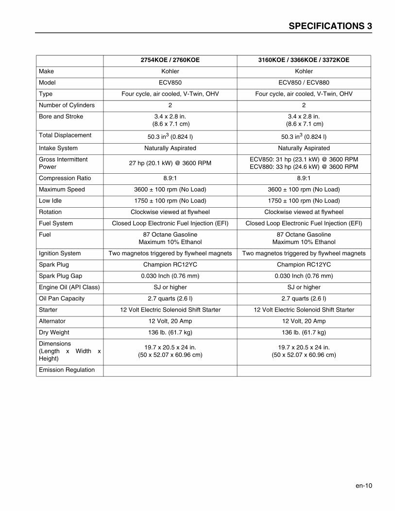
2754KOE / 2760KOE 3160KOE / 3366KOE / 3372KOE
Make Kohler Kohler
Model ECV850 ECV850 / ECV880
Type Four cycle, air cooled, V-Twin, OHV Four cycle, air cooled, V-Twin, OHV
Number of Cylinders 2 2
Bore and Stroke 3.4 x 2.8 in. (8.6 x 7.1 cm)
3.4 x 2.8 in. (8.6 x 7.1 cm)
Total Displacement 50.3 in3 (0.824 l) 50.3 in3 (0.824 l)
Intake System Naturally Aspirated Naturally Aspirated
Gross IntermittentPower
27 hp (20.1 kW) @ 3600 RPMECV850: 31 hp (23.1 kW) @ 3600 RPMECV880: 33 hp (24.6 kW) @ 3600 RPM
Compression Ratio 8.9:1 8.9:1
Maximum Speed 3600 ± 100 rpm (No Load) 3600 ± 100 rpm (No Load)
Low Idle 1750 ± 100 rpm (No Load) 1750 ± 100 rpm (No Load)
Rotation Clockwise viewed at flywheel Clockwise viewed at flywheel
Fuel System Closed Loop Electronic Fuel Injection (EFI) Closed Loop Electronic Fuel Injection (EFI)
Fuel 87 Octane GasolineMaximum 10% Ethanol
87 Octane GasolineMaximum 10% Ethanol
Ignition System Two magnetos triggered by flywheel magnets Two magnetos triggered by flywheel magnets
Spark Plug Champion RC12YC Champion RC12YC
Spark Plug Gap 0.030 Inch (0.76 mm) 0.030 Inch (0.76 mm)
Engine Oil (API Class) SJ or higher SJ or higher
Oil Pan Capacity 2.7 quarts (2.6 l) 2.7 quarts (2.6 l)
Starter 12 Volt Electric Solenoid Shift Starter 12 Volt Electric Solenoid Shift Starter
Alternator 12 Volt, 20 Amp 12 Volt, 20 Amp
Dry Weight 136 lb. (61.7 kg) 136 lb. (61.7 kg)
Dimensions(Length x Width xHeight)
19.7 x 20.5 x 24 in.(50 x 52.07 x 60.96 cm)
19.7 x 20.5 x 24 in.(50 x 52.07 x 60.96 cm)
Emission Regulation
3 SPECIFICATIONS
en-11
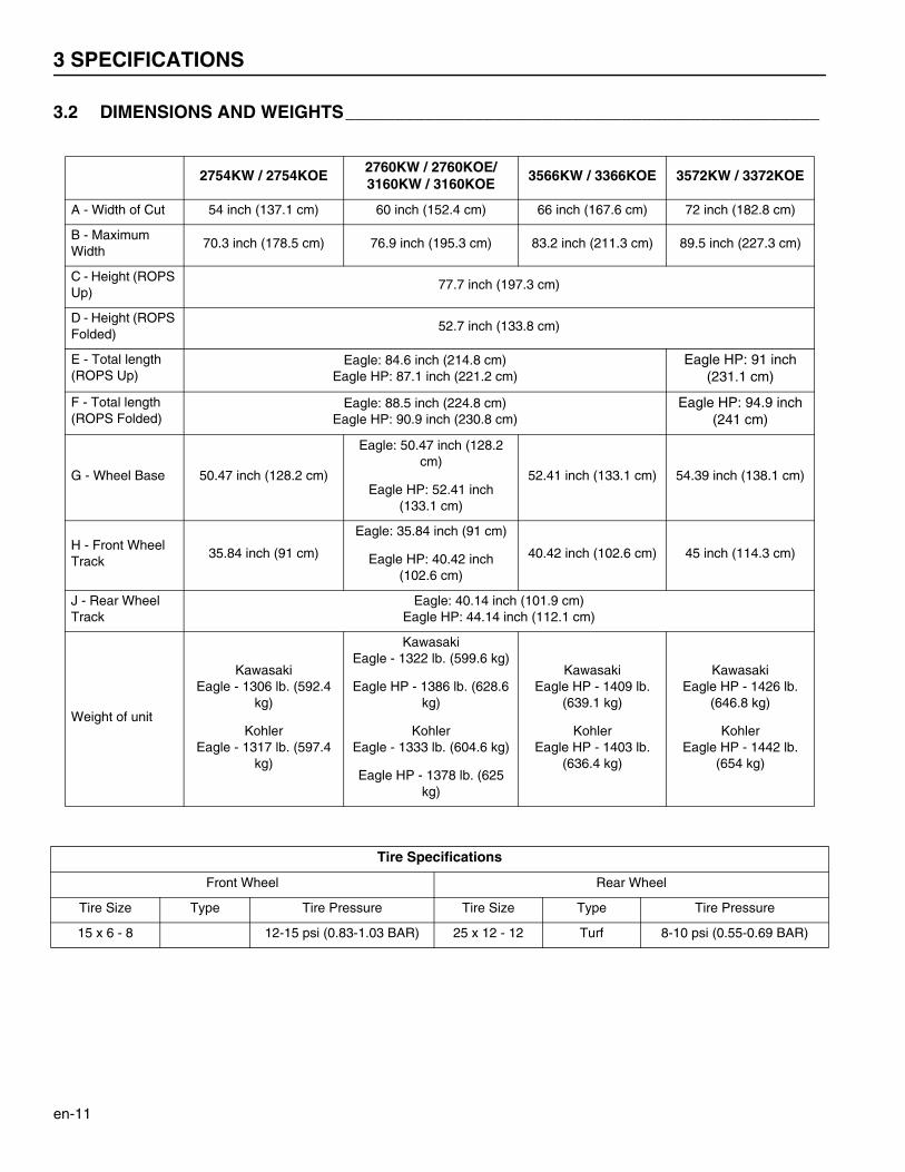
3.2 DIMENSIONS AND WEIGHTS________________________________________________
2754KW / 2754KOE2760KW / 2760KOE/3160KW / 3160KOE
3566KW / 3366KOE 3572KW / 3372KOE
A - Width of Cut 54 inch (137.1 cm) 60 inch (152.4 cm) 66 inch (167.6 cm) 72 inch (182.8 cm)
B - Maximum Width
70.3 inch (178.5 cm) 76.9 inch (195.3 cm) 83.2 inch (211.3 cm) 89.5 inch (227.3 cm)
C - Height (ROPS Up)
77.7 inch (197.3 cm)
D - Height (ROPS Folded)
52.7 inch (133.8 cm)
E - Total length (ROPS Up)
Eagle: 84.6 inch (214.8 cm)Eagle HP: 87.1 inch (221.2 cm)
Eagle HP: 91 inch (231.1 cm)
F - Total length (ROPS Folded)
Eagle: 88.5 inch (224.8 cm)Eagle HP: 90.9 inch (230.8 cm)
Eagle HP: 94.9 inch (241 cm)
G - Wheel Base 50.47 inch (128.2 cm)
Eagle: 50.47 inch (128.2 cm)
Eagle HP: 52.41 inch (133.1 cm)
52.41 inch (133.1 cm) 54.39 inch (138.1 cm)
H - Front Wheel Track
35.84 inch (91 cm)
Eagle: 35.84 inch (91 cm)
Eagle HP: 40.42 inch (102.6 cm)
40.42 inch (102.6 cm) 45 inch (114.3 cm)
J - Rear Wheel Track
Eagle: 40.14 inch (101.9 cm)Eagle HP: 44.14 inch (112.1 cm)
Weight of unit
KawasakiEagle - 1306 lb. (592.4
kg)
KohlerEagle - 1317 lb. (597.4
kg)
KawasakiEagle - 1322 lb. (599.6 kg)
Eagle HP - 1386 lb. (628.6 kg)
KohlerEagle - 1333 lb. (604.6 kg)
Eagle HP - 1378 lb. (625 kg)
KawasakiEagle HP - 1409 lb.
(639.1 kg)
KohlerEagle HP - 1403 lb.
(636.4 kg)
KawasakiEagle HP - 1426 lb.
(646.8 kg)
KohlerEagle HP - 1442 lb.
(654 kg)
Tire Specifications
Front Wheel Rear Wheel
Tire Size Type Tire Pressure Tire Size Type Tire Pressure
15 x 6 - 8 12-15 psi (0.83-1.03 BAR) 25 x 12 - 12 Turf 8-10 psi (0.55-0.69 BAR)

SPECIFICATIONS 3
en-12
F
D
J
H
AB
GE
C
3 SPECIFICATIONS
en-13
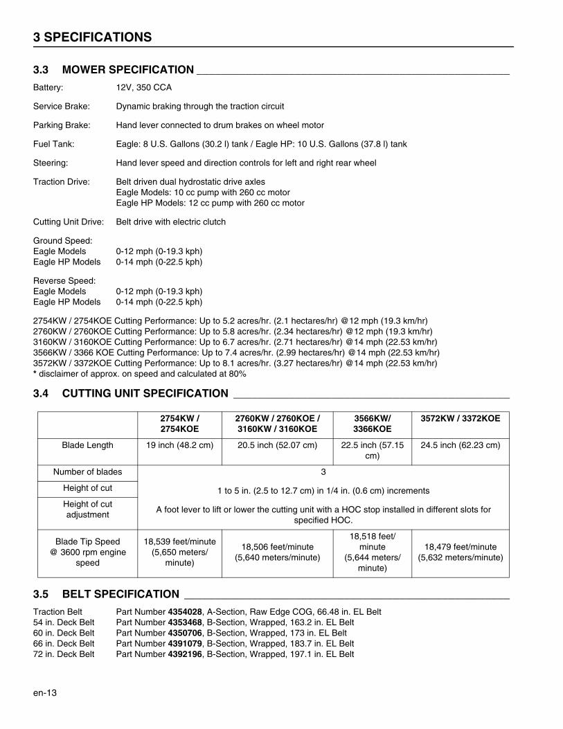
3.3 MOWER SPECIFICATION ___________________________________________________
Battery: 12V, 350 CCA
Service Brake: Dynamic braking through the traction circuit
Parking Brake: Hand lever connected to drum brakes on wheel motor
Fuel Tank: Eagle: 8 U.S. Gallons (30.2 l) tank / Eagle HP: 10 U.S. Gallons (37.8 l) tank
Steering: Hand lever speed and direction controls for left and right rear wheel
Traction Drive: Belt driven dual hydrostatic drive axlesEagle Models: 10 cc pump with 260 cc motorEagle HP Models: 12 cc pump with 260 cc motor
Cutting Unit Drive: Belt drive with electric clutch
Ground Speed:Eagle Models 0-12 mph (0-19.3 kph)Eagle HP Models 0-14 mph (0-22.5 kph)
Reverse Speed:Eagle Models 0-12 mph (0-19.3 kph)Eagle HP Models 0-14 mph (0-22.5 kph)
2754KW / 2754KOE Cutting Performance: Up to 5.2 acres/hr. (2.1 hectares/hr) @12 mph (19.3 km/hr)2760KW / 2760KOE Cutting Performance: Up to 5.8 acres/hr. (2.34 hectares/hr) @12 mph (19.3 km/hr)3160KW / 3160KOE Cutting Performance: Up to 6.7 acres/hr. (2.71 hectares/hr) @14 mph (22.53 km/hr)3566KW / 3366 KOE Cutting Performance: Up to 7.4 acres/hr. (2.99 hectares/hr) @14 mph (22.53 km/hr)3572KW / 3372KOE Cutting Performance: Up to 8.1 acres/hr. (3.27 hectares/hr) @14 mph (22.53 km/hr)* disclaimer of approx. on speed and calculated at 80%
3.4 CUTTING UNIT SPECIFICATION _____________________________________________
3.5 BELT SPECIFICATION _____________________________________________________
Traction Belt Part Number 4354028, A-Section, Raw Edge COG, 66.48 in. EL Belt54 in. Deck Belt Part Number 4353468, B-Section, Wrapped, 163.2 in. EL Belt60 in. Deck Belt Part Number 4350706, B-Section, Wrapped, 173 in. EL Belt66 in. Deck Belt Part Number 4391079, B-Section, Wrapped, 183.7 in. EL Belt72 in. Deck Belt Part Number 4392196, B-Section, Wrapped, 197.1 in. EL Belt
2754KW / 2754KOE
2760KW / 2760KOE / 3160KW / 3160KOE
3566KW/3366KOE
3572KW / 3372KOE
Blade Length 19 inch (48.2 cm) 20.5 inch (52.07 cm) 22.5 inch (57.15 cm)
24.5 inch (62.23 cm)
Number of blades 3
1 to 5 in. (2.5 to 12.7 cm) in 1/4 in. (0.6 cm) increments
A foot lever to lift or lower the cutting unit with a HOC stop installed in different slots for specified HOC.
Height of cut
Height of cut adjustment
Blade Tip Speed@ 3600 rpm engine
speed
18,539 feet/minute(5,650 meters/
minute)
18,506 feet/minute(5,640 meters/minute)
18,518 feet/minute
(5,644 meters/minute)
18,479 feet/minute(5,632 meters/minute)
SPECIFICATIONS 3
en-14
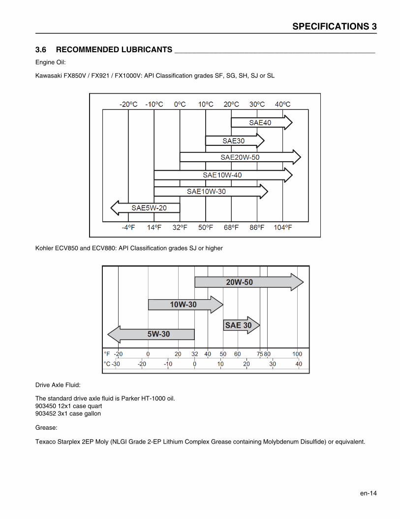
3.6 RECOMMENDED LUBRICANTS ______________________________________________
Engine Oil:
Kawasaki FX850V / FX921 / FX1000V: API Classification grades SF, SG, SH, SJ or SL
Kohler ECV850 and ECV880: API Classification grades SJ or higher
Drive Axle Fluid:
The standard drive axle fluid is Parker HT-1000 oil.903450 12x1 case quart903452 3x1 case gallon
Grease:
Texaco Starplex 2EP Moly (NLGI Grade 2-EP Lithium Complex Grease containing Molybdenum Disulfide) or equivalent.
3 SPECIFICATIONS
en-15
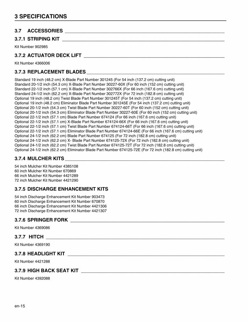
3.7 ACCESSORIES ___________________________________________________________
3.7.1 STRIPING KIT ____________________________________________________________
Kit Number 902985
3.7.2 ACTUATOR DECK LIFT ____________________________________________________
Kit Number 4366006
3.7.3 REPLACEMENT BLADES ___________________________________________________
Standard 19 inch (48.2 cm) X-Blade Part Number 301245 (For 54 inch (137.2 cm) cutting unit)Standard 20-1/2 inch (54.3 cm) X-Blade Part Number 30227-60X (For 60 inch (152 cm) cutting unit)Standard 22-1/2 inch (57.1 cm) X-Blade Part Number 302766X (For 66 inch (167.6 cm) cutting unit)Standard 24-1/2 inch (62.2 cm) X-Blade Part Number 302772X (For 72 inch (182.8 cm) cutting unit)Optional 19 inch (48.2 cm) Twist Blade Part Number 301245T (For 54 inch (137.2 cm) cutting unit)Optional 19 inch (48.2 cm) Eliminator Blade Part Number 301245E (For 54 inch (137.2 cm) cutting unit)Optional 20-1/2 inch (54.3 cm) Twist Blade Part Number 30227-60T (For 60 inch (152 cm) cutting unit)Optional 20-1/2 inch (54.3 cm) Eliminator Blade Part Number 30227-60E (For 60 inch (152 cm) cutting unit)Optional 22-1/2 inch (57.1 cm) Blade Part Number 674124 (For 66 inch (167.6 cm) cutting unit)Optional 22-1/2 inch (57.1 cm) X-Blade Part Number 674124-66X (For 66 inch (167.6 cm) cutting unit)Optional 22-1/2 inch (57.1 cm) Twist Blade Part Number 674124-66T (For 66 inch (167.6 cm) cutting unit)Optional 22-1/2 inch (57.1 cm) Eliminator Blade Part Number 674124-66E (For 66 inch (167.6 cm) cutting unit)Optional 24-1/2 inch (62.2 cm) Blade Part Number 674125 (For 72 inch (182.8 cm) cutting unit)Optional 24-1/2 inch (62.2 cm) X- Blade Part Number 674125-72X (For 72 inch (182.8 cm) cutting unit)Optional 24-1/2 inch (62.2 cm) Twist Blade Part Number 674125-72T (For 72 inch (182.8 cm) cutting unit)Optional 24-1/2 inch (62.2 cm) Eliminator Blade Part Number 674125-72E (For 72 inch (182.8 cm) cutting unit)
3.7.4 MULCHER KITS ___________________________________________________________
54 inch Mulcher Kit Number 438510860 inch Mulcher Kit Number 67086966 inch Mulcher Kit Number 442128972 inch Mulcher Kit Number 4421290
3.7.5 DISCHARGE ENHANCEMENT KITS
54 inch Discharge Enhancement Kit Number 90347360 inch Discharge Enhancement Kit Number 67087066 inch Discharge Enhancement Kit Number 442130672 inch Discharge Enhancement Kit Number 4421307
3.7.6 SPRINGER FORK _________________________________________________________
Kit Number 4369086
3.7.7 HITCH __________________________________________________________________
Kit Number 4369190
3.7.8 HEADLIGHT KIT __________________________________________________________
Kit Number 4421288
3.7.9 HIGH BACK SEAT KIT _____________________________________________________
Kit Number 4392088
SPECIFICATIONS 3
en-16
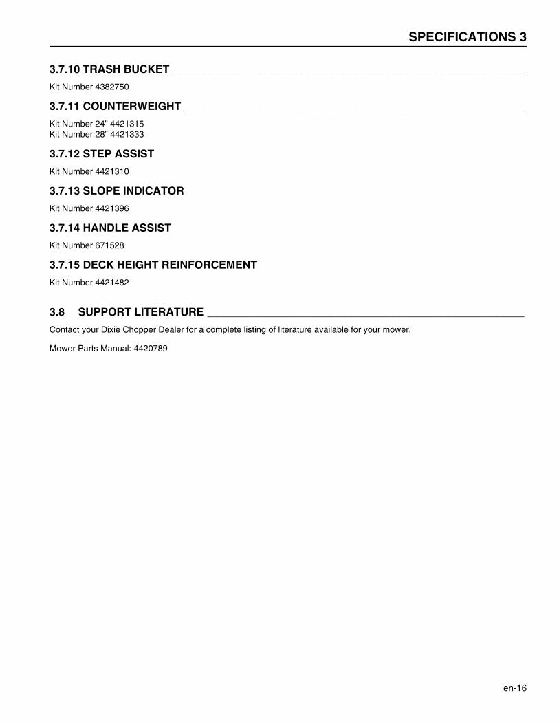
3.7.10 TRASH BUCKET__________________________________________________________
Kit Number 4382750
3.7.11 COUNTERWEIGHT ________________________________________________________
Kit Number 24” 4421315Kit Number 28” 4421333
3.7.12 STEP ASSIST
Kit Number 4421310
3.7.13 SLOPE INDICATOR
Kit Number 4421396
3.7.14 HANDLE ASSIST
Kit Number 671528
3.7.15 DECK HEIGHT REINFORCEMENT
Kit Number 4421482
3.8 SUPPORT LITERATURE ____________________________________________________
Contact your Dixie Chopper Dealer for a complete listing of literature available for your mower.
Mower Parts Manual: 4420789
4 DECALS
en-17
4Decals
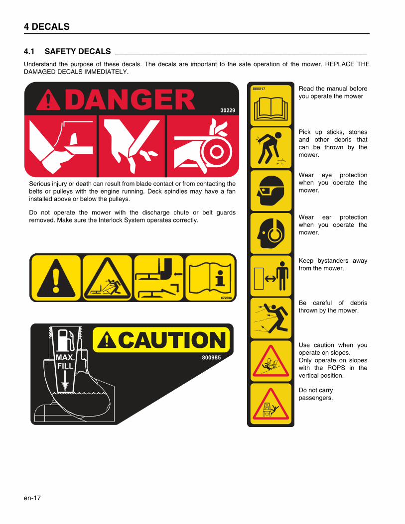
4.1 SAFETY DECALS _________________________________________________________
Understand the purpose of these decals. The decals are important to the safe operation of the mower. REPLACE THEDAMAGED DECALS IMMEDIATELY.
30229
800817 Read the manual beforeyou operate the mower
Pick up sticks, stonesand other debris thatcan be thrown by themower.
Wear eye protectionwhen you operate themower.
Wear ear protectionwhen you operate themower.
Keep bystanders awayfrom the mower.
Be careful of debristhrown by the mower.
Use caution when youoperate on slopes.Only operate on slopeswith the ROPS in thevertical position.
Do not carry passengers.
Serious injury or death can result from blade contact or from contacting thebelts or pulleys with the engine running. Deck spindles may have a faninstalled above or below the pulleys.
Do not operate the mower with the discharge chute or belt guardsremoved. Make sure the Interlock System operates correctly.
800985

DECALS 4
en-18
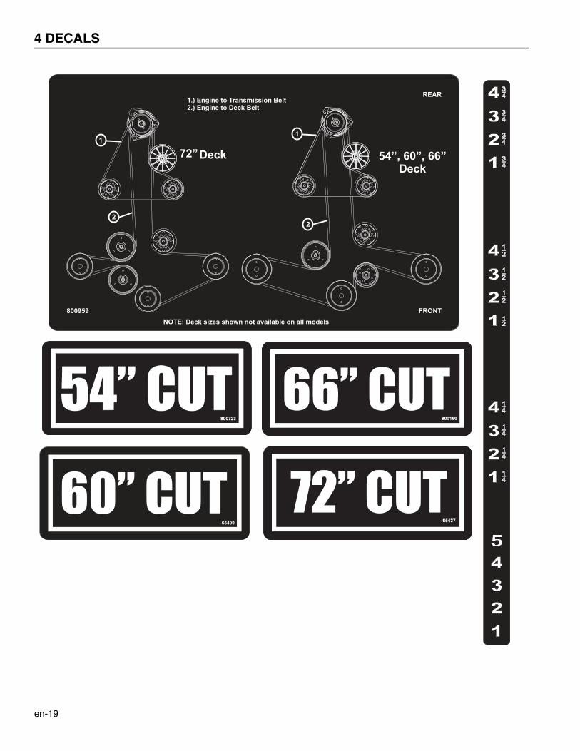
4.2 INSTRUCTION DECALS ____________________________________________________
800842
R
800843
L
800846
Fast Reverse
Slow Reverse
Slow Forward
Fast Forward
Neutral Neutral Lock Position
Neutral Lock Position
Left Side Steering Lever
Right Side Steering Lever
Engaged Position
Disengaged Position
Fast
Slow
Engine Throttle
4 DECALS
en-19
CONTROLS 5
en-20
5Controls
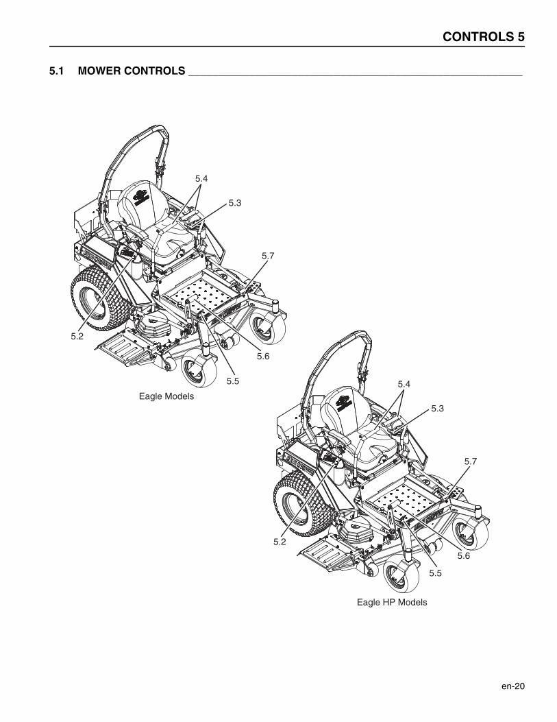
5.1 MOWER CONTROLS _______________________________________________________
5.5
5.2
5.4
5.3
5.7
5.6
Eagle Models
5.5
5.2
5.4
5.3
5.7
5.6
Eagle HP Models
5 CONTROLS
en-21
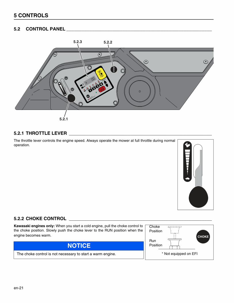
5.2 CONTROL PANEL _________________________________________________________
5.2.1 THROTTLE LEVER ________________________________________________________
The throttle lever controls the engine speed. Always operate the mower at full throttle during normaloperation.
5.2.2 CHOKE CONTROL ________________________________________________________
Kawasaki engines only: When you start a cold engine, pull the choke control tothe choke position. Slowly push the choke lever to the RUN position when theengine becomes warm.
NOTICEThe choke control is not necessary to start a warm engine.
CH
OK
E
5.2.3
5.2.1
5.2.2
E
START
STOP
CHOKE
ChokePosition
RunPosition
* Not equipped on EFI
CONTROLS 5
en-22
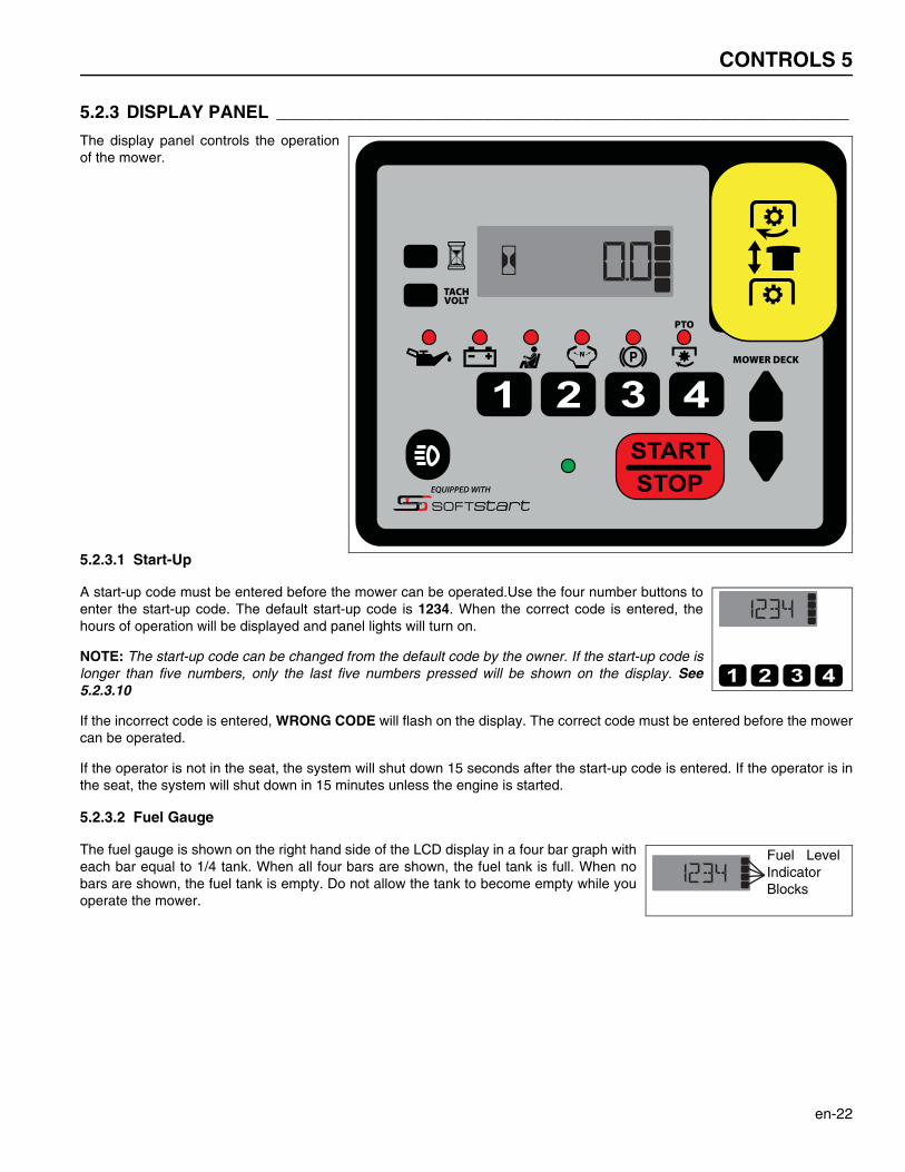
5.2.3 DISPLAY PANEL __________________________________________________________
The display panel controls the operationof the mower.
5.2.3.1 Start-Up
A start-up code must be entered before the mower can be operated.Use the four number buttons toenter the start-up code. The default start-up code is 1234. When the correct code is entered, thehours of operation will be displayed and panel lights will turn on.
NOTE: The start-up code can be changed from the default code by the owner. If the start-up code islonger than five numbers, only the last five numbers pressed will be shown on the display. See5.2.3.10
If the incorrect code is entered, WRONG CODE will flash on the display. The correct code must be entered before the mowercan be operated.
If the operator is not in the seat, the system will shut down 15 seconds after the start-up code is entered. If the operator is inthe seat, the system will shut down in 15 minutes unless the engine is started.
5.2.3.2 Fuel Gauge
The fuel gauge is shown on the right hand side of the LCD display in a four bar graph witheach bar equal to 1/4 tank. When all four bars are shown, the fuel tank is full. When nobars are shown, the fuel tank is empty. Do not allow the tank to become empty while youoperate the mower.
STARTSTOP
Fuel LevelIndicatorBlocks
5 CONTROLS
en-23
5.2.3.3 Warning Lights
Six red lights alert the operator of the mower status.
Engine Oil - The red engine oil pressure light indicates low engine oil pressure. Shut down the mower immediately.Inspect the oil level in the engine. If the oil light remains on with the oil at proper level, shut off the engine and tow ortrailer the mower back to a service area. NEVER operate the engine with the oil light on, severe damage to theengine can occur.
Battery Voltage - The battery voltage light indicates the system voltage is below 12 VDC or above 15 VDC. Havethe battery charging system checked.
Operator Presence - The operator in seat light indicates the seat switch is in the open position. The operator mustbe in the seat to start the engine. The engine will stop if the operator leaves the seat with the PTO switch ON,parking brake disengaged or the steering levers out of the neutral position.
Neutral Position - The neutral position light indicates the steering levers are not in the neutral position.
Parking Brake - The parking brake light indicates the parking brake is disengaged.
PTO Switch - The PTO switch light indicates the PTO switch is in the ON position.
5.2.3.4 Display Modes
During normal operation, the display panel can show the engine hour meter, service timer,blade run time, the engine speed and the system voltage on the LCD display. Alarms and errorcodes will override the display modes.
To display the engine hour meter, service timer or blade run time, press the hour meter buttonon the left side of the display. Press the hour meter button again to cycle between the screens.
To reset the service timer, press and release the hour meter button until the service timerscreen is on the display. Press and hold the hour meter button until the counter resets. Theblade run time and engine hour meter cannot be reset.
To display the engine speed or the system voltage, press the TACH/VOLT button on the leftside of the display. Press the button again to cycle between engine speed and system voltage.
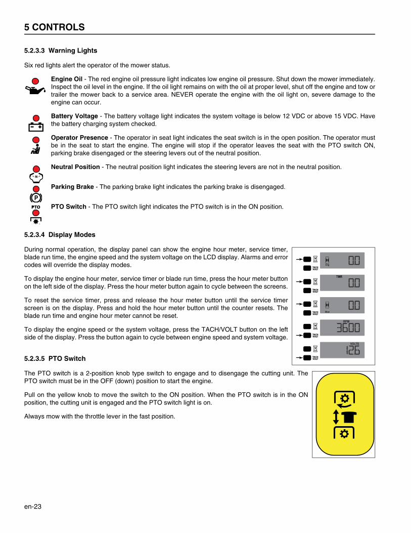
5.2.3.5 PTO Switch
The PTO switch is a 2-position knob type switch to engage and to disengage the cutting unit. ThePTO switch must be in the OFF (down) position to start the engine.
Pull on the yellow knob to move the switch to the ON position. When the PTO switch is in the ONposition, the cutting unit is engaged and the PTO switch light is on.
Always mow with the throttle lever in the fast position.
CONTROLS 5
en-24
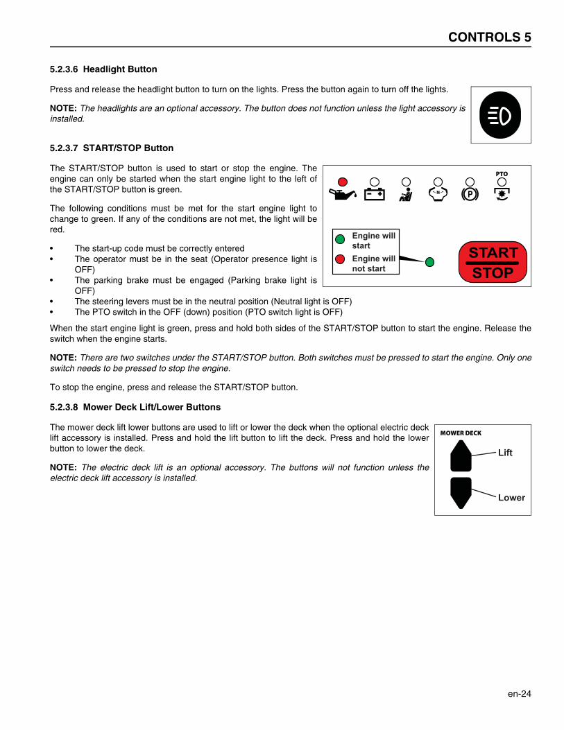
5.2.3.6 Headlight Button
Press and release the headlight button to turn on the lights. Press the button again to turn off the lights.
NOTE: The headlights are an optional accessory. The button does not function unless the light accessory isinstalled.
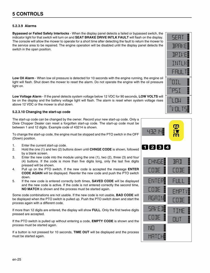
5.2.3.7 START/STOP Button
The START/STOP button is used to start or stop the engine. Theengine can only be started when the start engine light to the left ofthe START/STOP button is green.
The following conditions must be met for the start engine light tochange to green. If any of the conditions are not met, the light will bered.
• The start-up code must be correctly entered• The operator must be in the seat (Operator presence light is
OFF)• The parking brake must be engaged (Parking brake light is
OFF)• The steering levers must be in the neutral position (Neutral light is OFF)• The PTO switch in the OFF (down) position (PTO switch light is OFF)
When the start engine light is green, press and hold both sides of the START/STOP button to start the engine. Release theswitch when the engine starts.
NOTE: There are two switches under the START/STOP button. Both switches must be pressed to start the engine. Only oneswitch needs to be pressed to stop the engine.
To stop the engine, press and release the START/STOP button.
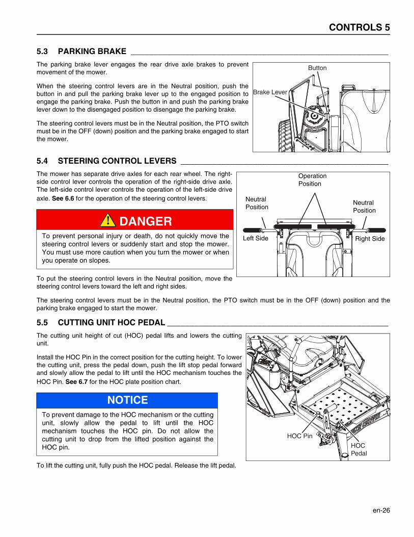
5.2.3.8 Mower Deck Lift/Lower Buttons
The mower deck lift lower buttons are used to lift or lower the deck when the optional electric decklift accessory is installed. Press and hold the lift button to lift the deck. Press and hold the lowerbutton to lower the deck.
NOTE: The electric deck lift is an optional accessory. The buttons will not function unless theelectric deck lift accessory is installed.
STARTSTOP
Engine willstartEngine willnot start
Lift
Lower
5 CONTROLS
en-25
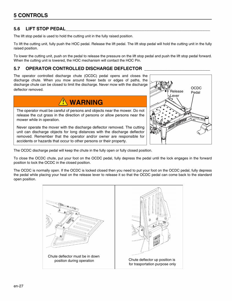
5.2.3.9 Alarms
Bypassed or Failed Safety Interlocks - When the display panel detects a failed or bypassed switch, theindicator light for that switch will turn on and SEAT BRAKE DRIVE INTLK FAULT will flash on the display.The console will allow the mower to operate for a short time after detecting the fault to return the mower tothe service area to be repaired. The engine operation will be disabled until the display panel detects theswitch in the open position.
Low Oil Alarm - When low oil pressure is detected for 10 seconds with the engine running, the engine oillight will flash. Shut down the mower to reset the alarm. Do not operate the engine with the oil pressurelight on.
Low Voltage Alarm - If the panel detects system voltage below 12 VDC for 90 seconds, LOW VOLTS willbe on the display and the battery voltage light will flash. The alarm is reset when system voltage risesabove 12 VDC or the mower is shut down.
5.2.3.10 Changing the start-up code
The start-up code can be changed by the owner. Record your new start-up code. Only aDixie Chopper Dealer can reset a forgotten start-up code. The start-up code must bebetween 1 and 12 digits. Example code of 43214 is shown.
To change the start-up code, the engine must be stopped and the PTO switch in the OFF(Down) position.
1. Enter the current start-up code.2. Hold the one (1) and two (2) buttons down until CHNGE CODE is shown, followed
by a blank screen.3. Enter the new code into the module using the one (1), two (2), three (3) and four
(4) buttons. If the code is more than five digits long, only the last five digitspressed will be shown.
4. Pull up on the PTO switch. If the new code is accepted the message ENTERCODE AGAIN will be displayed. Reenter the new code and push the PTO switchdown.
5. If the new code is entered correctly both times, SAVED CODE will be displayedand the new code is active. If the code is not entered correctly the second time,NO MATCH is shown and the process must be started again.
Some code combinations are not usable. If the new code is not usable, BAD CODE willbe displayed when the PTO switch is pulled up. Push the PTO switch down and start theprocess again with a different code.
If more than 12 digits are entered, the display will show FULL. Only the first twelve digitspressed are accepted.
If the PTO switch is pulled up without entering a code, EMPTY CODE is shown and theprocess must be started again.
If a button is not pressed for 10 seconds, TIME OUT will be displayed and the processmust be started again.
CONTROLS 5
en-26
5.3 PARKING BRAKE _________________________________________________________
The parking brake lever engages the rear drive axle brakes to preventmovement of the mower.
When the steering control levers are in the Neutral position, push thebutton in and pull the parking brake lever up to the engaged position toengage the parking brake. Push the button in and push the parking brakelever down to the disengaged position to disengage the parking brake.
The steering control levers must be in the Neutral position, the PTO switchmust be in the OFF (down) position and the parking brake engaged to startthe mower.
5.4 STEERING CONTROL LEVERS ______________________________________________
The mower has separate drive axles for each rear wheel. The right-side control lever controls the operation of the right-side drive axle.The left-side control lever controls the operation of the left-side driveaxle. See 6.6 for the operation of the steering control levers.
To put the steering control levers in the Neutral position, move thesteering control levers toward the left and right sides.
The steering control levers must be in the Neutral position, the PTO switch must be in the OFF (down) position and theparking brake engaged to start the mower.
5.5 CUTTING UNIT HOC PEDAL _________________________________________________
The cutting unit height of cut (HOC) pedal lifts and lowers the cuttingunit.
Install the HOC Pin in the correct position for the cutting height. To lowerthe cutting unit, press the pedal down, push the lift stop pedal forwardand slowly allow the pedal to lift until the HOC mechanism touches theHOC Pin. See 6.7 for the HOC plate position chart.
To lift the cutting unit, fully push the HOC pedal. Release the lift pedal.
DANGERTo prevent personal injury or death, do not quickly move thesteering control levers or suddenly start and stop the mower.You must use more caution when you turn the mower or whenyou operate on slopes.
NOTICETo prevent damage to the HOC mechanism or the cuttingunit, slowly allow the pedal to lift until the HOCmechanism touches the HOC pin. Do not allow thecutting unit to drop from the lifted position against theHOC pin.
Brake Lever
Button
OperationPosition
NeutralPosition
NeutralPosition
Left Side Right Side
!
HOC Pin
HOC Pedal
5 CONTROLS
en-27
5.6 LIFT STOP PEDAL_________________________________________________________
The lift stop pedal is used to hold the cutting unit in the fully raised position.
To lift the cutting unit, fully push the HOC pedal. Release the lift pedal. The lift stop pedal will hold the cutting unit in the fullyraised position.
To lower the cutting unit, push on the pedal to release the pressure on the lift stop pedal and push the lift stop pedal forward.When the cutting unit is lowered, the HOC mechanism will contact the HOC Pin.
5.7 OPERATOR CONTROLLED DISCHARGE DEFLECTOR __________________________
The operator controlled discharge chute (OCDC) pedal opens and closes thedischarge chute. When you mow around flower beds or edges of paths, thedischarge chute can be closed to limit the discharge. Never mow with the dischargedeflector removed.
The OCDC discharge pedal will keep the chute in the fully open or fully closed position.
To close the OCDC chute, put your foot on the OCDC pedal, fully depress the pedal until the lock engages in the forwardposition to lock the OCDC in the closed position.
The OCDC is normally open. If the OCDC is locked closed then you need to put your foot on the OCDC pedal, fully depressthe pedal while placing your heal on the release lever to release it so that the OCDC pedal can come back to the standardopen position.
WARNINGThe operator must be careful of persons and objects near the mower. Do notrelease the cut grass in the direction of persons or allow persons near themower while in operation.
Never operate the mover with the discharge deflector removed. The cuttingunit can discharge objects for long distances with the discharge deflectorremoved. Remember that the operator and/or owner are responsible foraccidents or hazards that occur to other persons or their property.
Release Lever
OCDC Pedal
!
Chute deflector must be in down position during operation Chute deflector up position is
for trasportation purpose only
OPERATION 6
en-28
6Operation
6.1 DAILY INSPECTION ________________________________________________________
Do a visual inspection of the mower. Look for indications of wear or loose hardware. Look for any components that are notincluded on the mower or damaged components. Check for fuel and oil leaks to make sure the connections are tight. Makesure that all hoses are in good condition.
Check the fuel supply and crankcase oil level. When the engine is cold, all fluids must be at the full level mark.
Check the engine oil cooler fins for dirt or grass. Clean with compressed air as required before you operate the mower.
Check all tires for the correct pressure.
Test the Interlock system.
CAUTIONThe inspection must be done each day when the engine is turned off and all fluids are cold. Lower the cutting unitsto the ground, engage the parking brake, stop the engine and remove the ignition key.
!
6 OPERATION
en-29
6.2 INTERLOCK SYSTEM ______________________________________________________
The Eagle Interlock System prevents the engine to start unless the steering control levers are in the Neutral position and thePTO switch is in the OFF (Down) position. The system stops the engine if the operator leaves the seat with the PTO switch inthe ON position, steering control levers out of the NEUTRAL position or the parking brake disengaged.
Do each of these tests to make sure the Interlock System operates correctly. If any of the tests fail, stop the test and have thesystem inspected and repaired as shown below:
• The engine does not start during test 1• The engine does start during tests 2, 3 and 4• The engine continues to run during tests 5 and 6
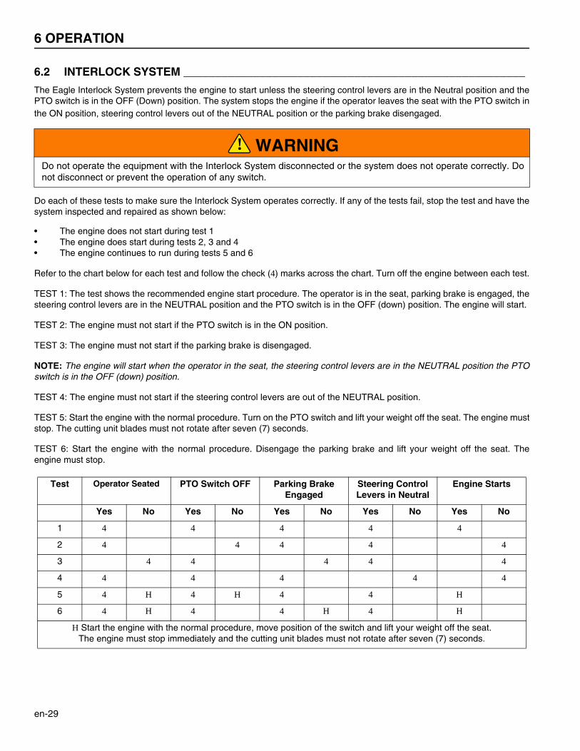
Refer to the chart below for each test and follow the check (4) marks across the chart. Turn off the engine between each test.
TEST 1: The test shows the recommended engine start procedure. The operator is in the seat, parking brake is engaged, thesteering control levers are in the NEUTRAL position and the PTO switch is in the OFF (down) position. The engine will start.
TEST 2: The engine must not start if the PTO switch is in the ON position.
TEST 3: The engine must not start if the parking brake is disengaged.
NOTE: The engine will start when the operator in the seat, the steering control levers are in the NEUTRAL position the PTOswitch is in the OFF (down) position.
TEST 4: The engine must not start if the steering control levers are out of the NEUTRAL position.
TEST 5: Start the engine with the normal procedure. Turn on the PTO switch and lift your weight off the seat. The engine muststop. The cutting unit blades must not rotate after seven (7) seconds.
TEST 6: Start the engine with the normal procedure. Disengage the parking brake and lift your weight off the seat. Theengine must stop.
WARNINGDo not operate the equipment with the Interlock System disconnected or the system does not operate correctly. Donot disconnect or prevent the operation of any switch.
Test Operator Seated PTO Switch OFF Parking Brake Engaged
Steering Control Levers in Neutral
Engine Starts
Yes No Yes No Yes No Yes No Yes No
1 4 4 4 4 4
2 4 4 4 4 4
3 4 4 4 4 4
4 4 4 4 4 4
5 4 H 4 H 4 4 H
6 4 H 4 4 H 4 H
H Start the engine with the normal procedure, move position of the switch and lift your weight off the seat. The engine must stop immediately and the cutting unit blades must not rotate after seven (7) seconds.
!
OPERATION 6
en-30
6.3 OPERATING PROCEDURE __________________________________________________
1. Always start the engine with the operator in the seat, never while next to the mower. Never start the engine with persons near the mower.
2. Never operate the engine without enough ventilation or in an enclosed area. The carbon monoxide in the exhaustfumes can increase to dangerous levels.
3. If the low engine oil pressure alarm turns on, shut down the mower immediately. Inspect the oil level in the engine. If thealarm remains on with the oil at proper level, shut off the engine and tow or trailer the mower back to a service area.NEVER operate the engine with the alarm on, severe damage to the engine can occur.
4. Keep your hands and feet away from moving parts and the cutting units. When possible, do not adjust the mower withthe engine started.
5. Do not operate the mower with loose or damaged components. All components must be correctly fastened to themower. Mow when the grass is dry to get the best results.
6. First cut in a test area so that you completely understand the operation of the tractor and controls.7. Inspect the area to find the safest procedure for the mower. Check the height of the grass, the type of terrain and the
conditions of the surface. Each condition needs the correct adjustments and precautions.8. Do not release the cut grass in the direction of persons or allow persons near the mower while in operation. The owner
and operator are responsible for injuries caused to persons near the mower and any damage to their property.
9. Be careful when you operate near to gravel areas (roads, parking areas, cart paths). Stones released from theequipment can cause injuries to persons and cause damage to the equipment.
10. When you are not mowing grass, always turn off the PTO switch.11. Before you move across or operate on the paths or roads, turn off the PTO switch, lift the cutting unit and travel at
decreased speed. Look for traffic.12. When you hit an object or mower starts to cause vibration that is not normal, inspect the mower for damage and make
repairs.13. Travel at decreased speed and be careful when you operate on the slopes or near sharp edges.14. When you drive in the reverse direction, look behind you and down to make sure the path is clear. Use caution when
you go near corners, trees or other objects that can prevent a clear view.15. Never use your hands to clean the cutting units. Use a brush to remove the grass clippings from the blades. The blades
are sharp and can cause injuries.
WARNINGThis mower has a folding Roll Over Protection Structure (ROPS). Always wear the seat belt with the ROPS frame inthe vertical and locked position. Never wear the seat belt with the ROPS in the folded position.
If the mower is over turning and the ROPS is in the vertical and locked position, hold the steering wheel. Do not tryto move off the mower or leave the seat.
CAUTIONTo prevent injury, always wear the safety glasses, leather work shoes or boots, a hard hat and ear protection.
WARNINGRemove all objects you can find before you operate the mower. Carefully enter a new area and always operate atspeeds that allow you to control the mower safely.
Before you clean, adjust or repair this equipment, always turn off the PTO switch, lower the cutting unit to theground, turn on the parking brake switch, stop the engine and remove the ignition key.
!
!
!
6 OPERATION
en-31
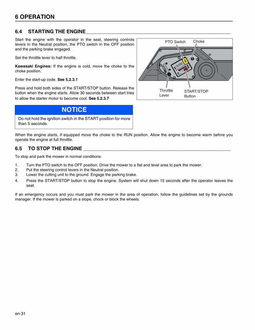
6.4 STARTING THE ENGINE____________________________________________________
Start the engine with the operator in the seat, steering controlslevers in the Neutral position, the PTO switch in the OFF positionand the parking brake engaged.
Set the throttle lever to half throttle.
Kawasaki Engines: If the engine is cold, move the choke to thechoke position.
Enter the start-up code. See 5.2.3.1
Press and hold both sides of the START/STOP button. Release thebutton when the engine starts. Allow 30 seconds between start triesto allow the starter motor to become cool. See 5.2.3.7
When the engine starts, if equipped move the choke to the RUN position. Allow the engine to become warm before youoperate the engine at full throttle.
6.5 TO STOP THE ENGINE _____________________________________________________
To stop and park the mower in normal conditions:
1. Turn the PTO switch to the OFF position. Drive the mower to a flat and level area to park the mower.2. Put the steering control levers in the Neutral position.3. Lower the cutting unit to the ground. Engage the parking brake.
4. Press the START/STOP button to stop the engine. System will shut down 15 seconds after the operator leaves theseat.
If an emergency occurs and you must park the mower in the area of operation, follow the guidelines set by the groundsmanager. If the mower is parked on a slope, chock or block the wheels.
NOTICEDo not hold the ignition switch in the START position for morethan 5 seconds.
CH
OK
E
E
START
STOP
PTO Switch
ThrottleLever
START/STOPButton
Choke
OPERATION 6
en-32
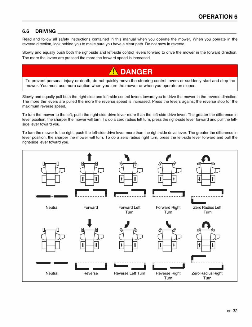
6.6 DRIVING _________________________________________________________________
Read and follow all safety instructions contained in this manual when you operate the mower. When you operate in thereverse direction, look behind you to make sure you have a clear path. Do not mow in reverse.
Slowly and equally push both the right-side and left-side control levers forward to drive the mower in the forward direction.The more the levers are pressed the more the forward speed is increased.
Slowly and equally pull both the right-side and left-side control levers toward you to drive the mower in the reverse direction.The more the levers are pulled the more the reverse speed is increased. Press the levers against the reverse stop for themaximum reverse speed.
To turn the mower to the left, push the right-side drive lever more than the left-side drive lever. The greater the difference inlever position, the sharper the mower will turn. To do a zero radius left turn, press the right-side lever forward and pull the left-side lever toward you.
To turn the mower to the right, push the left-side drive lever more than the right-side drive lever. The greater the difference inlever position, the sharper the mower will turn. To do a zero radius right turn, press the left-side lever forward and pull theright-side lever toward you.
DANGERTo prevent personal injury or death, do not quickly move the steering control levers or suddenly start and stop themower. You must use more caution when you turn the mower or when you operate on slopes.
!
Neutral Forward Forward Left Turn
Forward Right Turn
Zero Radius Left Turn
Neutral Reverse Reverse Left Turn Reverse Right Turn
Zero Radius Right Turn
6 OPERATION
en-33
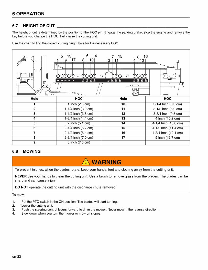
6.7 HEIGHT OF CUT __________________________________________________________
The height of cut is determined by the position of the HOC pin. Engage the parking brake, stop the engine and remove thekey before you change the HOC. Fully raise the cutting unit.
Use the chart to find the correct cutting height hole for the necessary HOC.
6.8 MOWING_________________________________________________________________________
To mow:
1. Put the PTO switch in the ON position. The blades will start turning.2. Lower the cutting unit.3. Push the steering control levers forward to drive the mower. Never mow in the reverse direction.4. Slow down when you turn the mower or mow on slopes.
Hole HOC Hole HOC
1 1 Inch (2.5 cm) 10 3-1/4 Inch (8.3 cm)2 1-1/4 Inch (3.2 cm) 11 3-1/2 Inch (8.9 cm)3 1-1/2 Inch (3.8 cm) 12 3-3/4 Inch (9.5 cm)4 1-3/4 Inch (4.4 cm) 13 4 Inch (10.2 cm)5 2 Inch (5.1 cm) 14 4-1/4 Inch (10.8 cm)6 2-1/4 Inch (5.7 cm) 15 4-1/2 Inch (11.4 cm)7 2-1/2 Inch (6.4 cm) 16 4-3/4 Inch (12.1 cm)8 2-3/4 Inch (7.0 cm) 17 5 Inch (12.7 cm)9 3 Inch (7.6 cm)
WARNINGTo prevent injuries, when the blades rotate, keep your hands, feet and clothing away from the cutting unit.
NEVER use your hands to clean the cutting unit. Use a brush to remove grass from the blades. The blades can besharp and can cause injury.
DO NOT operate the cutting unit with the discharge chute removed.
15
913
17 26
1014
37
1115
48
1216
!
OPERATION 6
en-34
6.9 MOWING ON SLOPES ______________________________________________________
The mower is made to have good traction and to have goodbalance. Operate the mower with caution when you drive on aslope. If you drive on wet grass, the traction and steering controlof the mower is decreased.
1. Always cut the grass with the engine at full throttle. Control the forward speed with the steering control levers to keep the correct performance.
2. If the mower moves to the side or the tires damage theturf, drive the mower on a slope with a decreased angle.
3. If the mower continues to move to the side and damagethe turf, the slope is at an angle that is not safe. Do notcontinue to drive toward the top of the slope. Carefullydrive toward the bottom of the slope.
4. When you drive toward the bottom of a slope with a highangle, lower the cutting unit to the ground. This proceduremakes sure the mower does not turn upside down.
5. Correct tire pressure is necessary for maximum traction.Rear - 8-10 psi (0.55-0.69 BAR)Front - 12-15 psi (0.83-1.03 BAR)
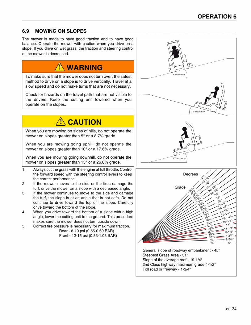
WARNINGTo make sure that the mower does not turn over, the safestmethod to drive on a slope is to drive vertically. Travel at aslow speed and do not make turns that are not necessary.
Check for hazards on the travel path that are not visible tothe drivers. Keep the cutting unit lowered when youoperate on the slopes.
CAUTIONWhen you are mowing on sides of hills, do not operate themower on slopes greater than 5° or a 8.7% grade.
When you are mowing going uphill, do not operate themower on slopes greater than 10° or a 17.6% grade.
When you are mowing going downhill, do not operate themower on slopes greater than 15° or a 26.8% grade.
15° Maximum
5° Maximum
10° Maximum
!
!
0°0%2-3/4°5%5-3/4°
10%
8-1/2°15%
11-1/4°20%
14°
25%
16-3/4°
30%
19-1/4°
35%
21-3/4°
40%
24-1/4°
45%
26-1/2°
50%
28-3/4°
55%
31°
60%
33°
65%
35°
70%
36-3/4°
75%
38-3/4°
80%
40-1/4°
85%
42°
90%
43-1
/2°
95%
45°
100%
General slope of roadway embankment - 45°Steepest Grass Area - 31°Slope of the average roof - 19-1/4°2nd Class highway maximum grade 4-1/2°Toll road or freeway - 1-3/4°
Grade
Degrees
6 OPERATION
en-35
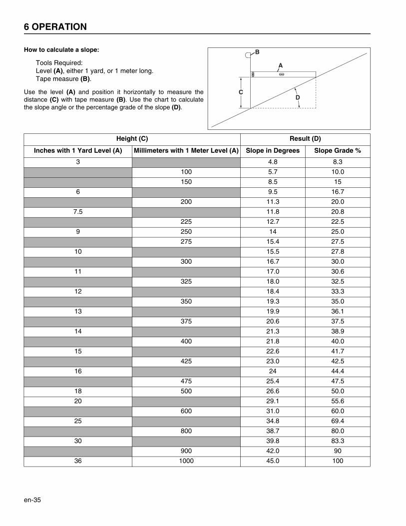
How to calculate a slope:
Tools Required:Level (A), either 1 yard, or 1 meter long.Tape measure (B).
Use the level (A) and position it horizontally to measure thedistance (C) with tape measure (B). Use the chart to calculatethe slope angle or the percentage grade of the slope (D).
Height (C) Result (D)
Inches with 1 Yard Level (A) Millimeters with 1 Meter Level (A) Slope in Degrees Slope Grade %
3 4.8 8.3
100 5.7 10.0
150 8.5 15
6 9.5 16.7
200 11.3 20.0
7.5 11.8 20.8
225 12.7 22.5
9 250 14 25.0
275 15.4 27.5
10 15.5 27.8
300 16.7 30.0
11 17.0 30.6
325 18.0 32.5
12 18.4 33.3
350 19.3 35.0
13 19.9 36.1
375 20.6 37.5
14 21.3 38.9
400 21.8 40.0
15 22.6 41.7
425 23.0 42.5
16 24 44.4
475 25.4 47.5
18 500 26.6 50.0
20 29.1 55.6
600 31.0 60.0
25 34.8 69.4
800 38.7 80.0
30 39.8 83.3
900 42.0 90
36 1000 45.0 100
C
A
B
D

OPERATION 6
en-36
6.10 TOWING THE MOWER______________________________________________________
If the mower has a problem and can not drive to the service area, open the bypass valve and load the mower on a trailer. If atrailer is not available, tow the mower at a slow speed for short distances.
Be careful when you load or unload the mower on the trailer. Fasten the mower to the trailer to prevent the mower to move onthe trailer. Engage the parking brake.
If the trailer is moved on the highway, inflate the tires to the maximum pressure recorded on the tire before you fasten themower to the trailer. Decrease the tire pressure after the mower is removed from the trailer.
Open the bypass valve on both drive axles before you tow themower. The bypass valve lets the mower be moved without theengine started and to prevent possible damage to drive axlecomponents.
The bypass valve is found on the front side of the left and rightdrive axles. To open the valve, turn the lever 90° in the directionindicated by the arrow.
Before towing, disengage the parking brake and make sure thecutting unit is lifted.
When the mower gets to the service area, engage the parking brake and close the bypass valves.
NOTICEWhen you tow the mower, do not drive more than 2 mph (3.2 km/hr). Dixie Chopper recommends that you do nottow the mower for long distances.
Bypass Valves
Left PumpRight Pump
7 MAINTENANCE AND LUBRICATION CHARTS
en-37
7Maintenance and Lubrication Charts
7.1 MAINTENANCE CHART ____________________________________________________
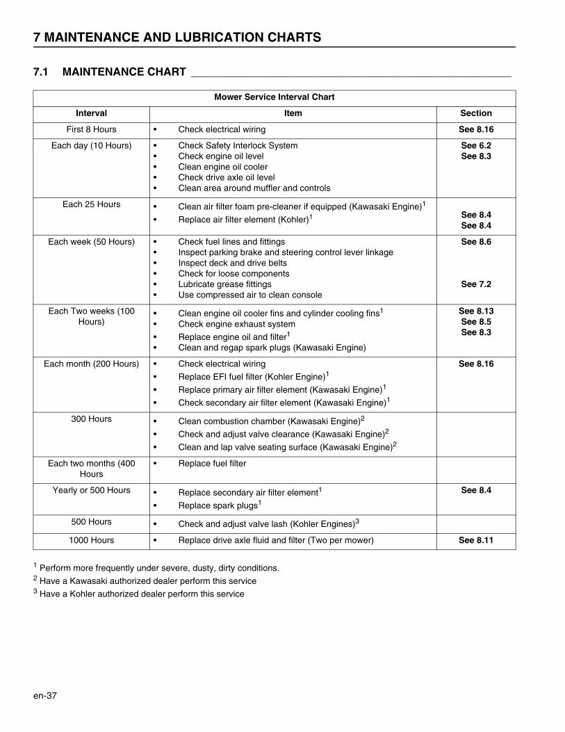
1 Perform more frequently under severe, dusty, dirty conditions.2 Have a Kawasaki authorized dealer perform this service3 Have a Kohler authorized dealer perform this service
Mower Service Interval Chart
Interval Item Section
First 8 Hours • Check electrical wiring See 8.16
Each day (10 Hours) • Check Safety Interlock System• Check engine oil level• Clean engine oil cooler• Check drive axle oil level• Clean area around muffler and controls
See 6.2See 8.3
Each 25 Hours • Clean air filter foam pre-cleaner if equipped (Kawasaki Engine)1
• Replace air filter element (Kohler)1 See 8.4See 8.4
Each week (50 Hours) • Check fuel lines and fittings• Inspect parking brake and steering control lever linkage• Inspect deck and drive belts• Check for loose components• Lubricate grease fittings • Use compressed air to clean console
See 8.6
See 7.2
Each Two weeks (100 Hours)
• Clean engine oil cooler fins and cylinder cooling fins1
• Check engine exhaust system
• Replace engine oil and filter1
• Clean and regap spark plugs (Kawasaki Engine)
See 8.13See 8.5See 8.3
Each month (200 Hours) • Check electrical wiring
• Replace EFI fuel filter (Kohler Engine)1
• Replace primary air filter element (Kawasaki Engine)1
• Check secondary air filter element (Kawasaki Engine)1
See 8.16
300 Hours • Clean combustion chamber (Kawasaki Engine)2
• Check and adjust valve clearance (Kawasaki Engine)2
• Clean and lap valve seating surface (Kawasaki Engine)2
Each two months (400 Hours
• Replace fuel filter
Yearly or 500 Hours • Replace secondary air filter element1
• Replace spark plugs1
See 8.4
500 Hours • Check and adjust valve lash (Kohler Engines)3
1000 Hours • Replace drive axle fluid and filter (Two per mower) See 8.11
MAINTENANCE AND LUBRICATION CHARTS 7
en-38
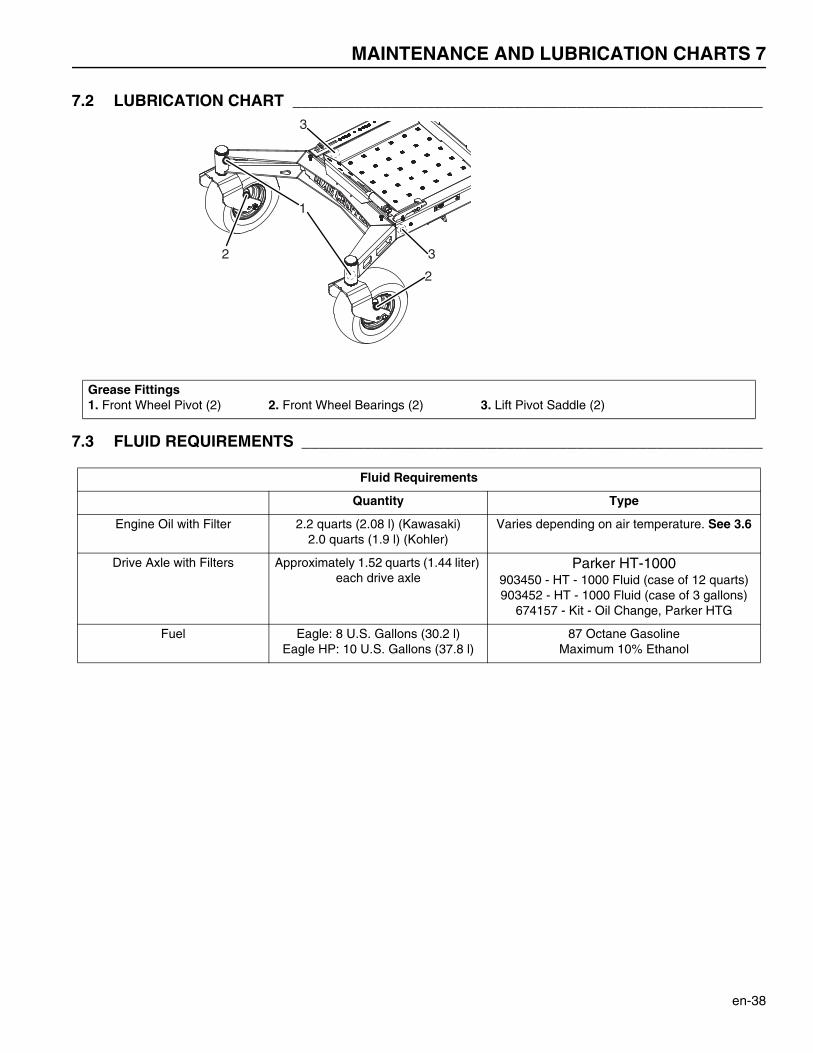
7.2 LUBRICATION CHART _____________________________________________________
7.3 FLUID REQUIREMENTS ____________________________________________________
Grease Fittings1. Front Wheel Pivot (2) 2. Front Wheel Bearings (2) 3. Lift Pivot Saddle (2)
Fluid Requirements
Quantity Type
Engine Oil with Filter 2.2 quarts (2.08 l) (Kawasaki)2.0 quarts (1.9 l) (Kohler)
Varies depending on air temperature. See 3.6
Drive Axle with Filters Approximately 1.52 quarts (1.44 liter) each drive axle
Parker HT-1000903450 - HT - 1000 Fluid (case of 12 quarts)903452 - HT - 1000 Fluid (case of 3 gallons)
674157 - Kit - Oil Change, Parker HTG
Fuel Eagle: 8 U.S. Gallons (30.2 l)Eagle HP: 10 U.S. Gallons (37.8 l)
87 Octane GasolineMaximum 10% Ethanol
2
1
3
2
3

8 MAINTENANCE
en-39
8Maintenance
8.1 GENERAL PRECAUTIONS ________________________________________________________
A qualified technician must always do adjustments and maintenance. If the correct adjustments can not be made, contactyour Dixie Chopper Dealer.
Inspect the equipment according to the maintenance schedule and keep complete records.
a Keep the equipment clean.
b Keep all moving parts correctly adjusted and lubricated.
c Replace worn or damaged parts before you operate the mower.
d Keep all fluids at the correct level.
e Keep the shields in position and all hardware tight.
f Keep the tires correctly inflated.
When you make the adjustments or repairs, do not wear jewelry or loose fitting clothing.
Refer to the illustrations in the Parts Manual for the removal and assembly of parts.
When you discard hazardous materials (batteries, lubricants, fuel, anti-freeze), follow your local, state or federal-recommended procedures.
8.2 ENGINE _________________________________________________________________
IMPORTANT - The mower includes a separate Engine Manual prepared by the engine manufacturer. Read the EngineManual and know the operation and maintenance of the engine. When you follow the engine manufacturer instructions, youwill make sure of the maximum service life of the engine. The replacement engine manuals are available from the enginemanufacturer.
The operation and maintenance during the first 8 hours of a new engine can make a difference to the performance and life ofthe engine.
During the first 8 hours of operation, Dixie Chopper recommends the following.
• Allow the engine to reach a temperature of at least 140° F (60° C) before operation at full load.• Check the engine oil level two times each day. Higher than normal oil use can occur during the first 8 hours.• Change the engine oil and oil filter after the first 8 hours of operation.• Refer to the Engine manual for specified maintenance intervals.
WARNINGBefore you clean, adjust or repair this equipment, push PTO switch to the OFF position, lower the cutting unit,engage the parking brake, stop the engine and remove the key.
Make sure the mower is parked on a solid and level surface. Never work on a mower that is lifted only by the jack.Always use the jack stands.
NOTICEThe mower operates and cuts correctly at the preset governor setting. Do not change the engine governor settingor over speed the engine.
!
MAINTENANCE 8
en-40
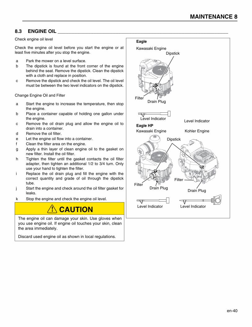
8.3 ENGINE OIL ______________________________________________________________
Check engine oil level
Check the engine oil level before you start the engine or atleast five minutes after you stop the engine.
a Park the mower on a level surface. b The dipstick is found at the front corner of the engine
behind the seat. Remove the dipstick. Clean the dipstickwith a cloth and replace in position.
c Remove the dipstick and check the oil level. The oil levelmust be between the two level indicators on the dipstick.
Change Engine Oil and Filter
a Start the engine to increase the temperature, then stopthe engine.
b Place a container capable of holding one gallon underthe engine.
c Remove the oil drain plug and allow the engine oil todrain into a container.
d Remove the oil filter. e Let the engine oil flow into a container. f Clean the filter area on the engine. g Apply a thin layer of clean engine oil to the gasket on
new filter. Install the oil filter. h Tighten the filter until the gasket contacts the oil filter
adapter, then tighten an additional 1/2 to 3/4 turn. Onlyuse your hand to tighten the filter.
i Replace the oil drain plug and fill the engine with thecorrect quantity and grade of oil through the dipsticktube.
j Start the engine and check around the oil filter gasket forleaks.
k Stop the engine and check the engine oil level.
CAUTIONThe engine oil can damage your skin. Use gloves whenyou use engine oil. If engine oil touches your skin, cleanthe area immediately.
Discard used engine oil as shown in local regulations.
ADD FULL
ADD FULL
Dipstick
Level Indicator Level Indicator
Kohler EngineKawasaki Engine
Dipstick
FilterFilter
Filter
Drain PlugDrain Plug
Drain Plug
Kawasaki Engine
Eagle
Eagle HPLevel Indicator
Level Indicator
!
8 MAINTENANCE
en-41
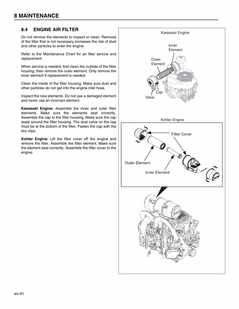
8.4 ENGINE AIR FILTER
Do not remove the elements to inspect or clean. Removalof the filter that is not necessary increases the risk of dustand other particles to enter the engine.
Refer to the Maintenance Chart for air filter service andreplacement.
When service is needed, first clean the outside of the filterhousing, then remove the outer element. Only remove theinner element if replacement is needed.
Clean the inside of the filter housing. Make sure dust andother particles do not get into the engine inlet hose.
Inspect the new elements. Do not use a damaged elementand never use an incorrect element.
Kawasaki Engine: Assemble the inner and outer filterelements. Make sure the elements seat correctly.Assemble the cap to the filter housing. Make sure the capseals around the filter housing. The dust valve on the capmust be at the bottom of the filter. Fasten the cap with thetwo clips.
Kohler Engine: Lift the filter cover off the engine andremove the filter. Assemble the filter element. Make surethe element seat correctly. Assemble the filter cover to theengine.
Inner Element
Kawasaki Engine
Kohler Engine
Outer Element
ValveCap
MAINTENANCE 8
en-42
8.5 ENGINE EXHAUST _______________________________________________________________
If you sense a change in the color or sound of the exhaust, stop the engine immediately. Identify the problem and have thesystem repaired.
Torque all exhaust manifold hardware equally. Tighten or replace the exhaust clamps.
8.6 FUEL ____________________________________________________________________
Gasoline is flammable. Use caution when you add the fuel to the mower. Only use an approved container. The spout onthe container must fit inside the fuel filler neck. Never use the containers that are not approved to keep or transfer fuel.
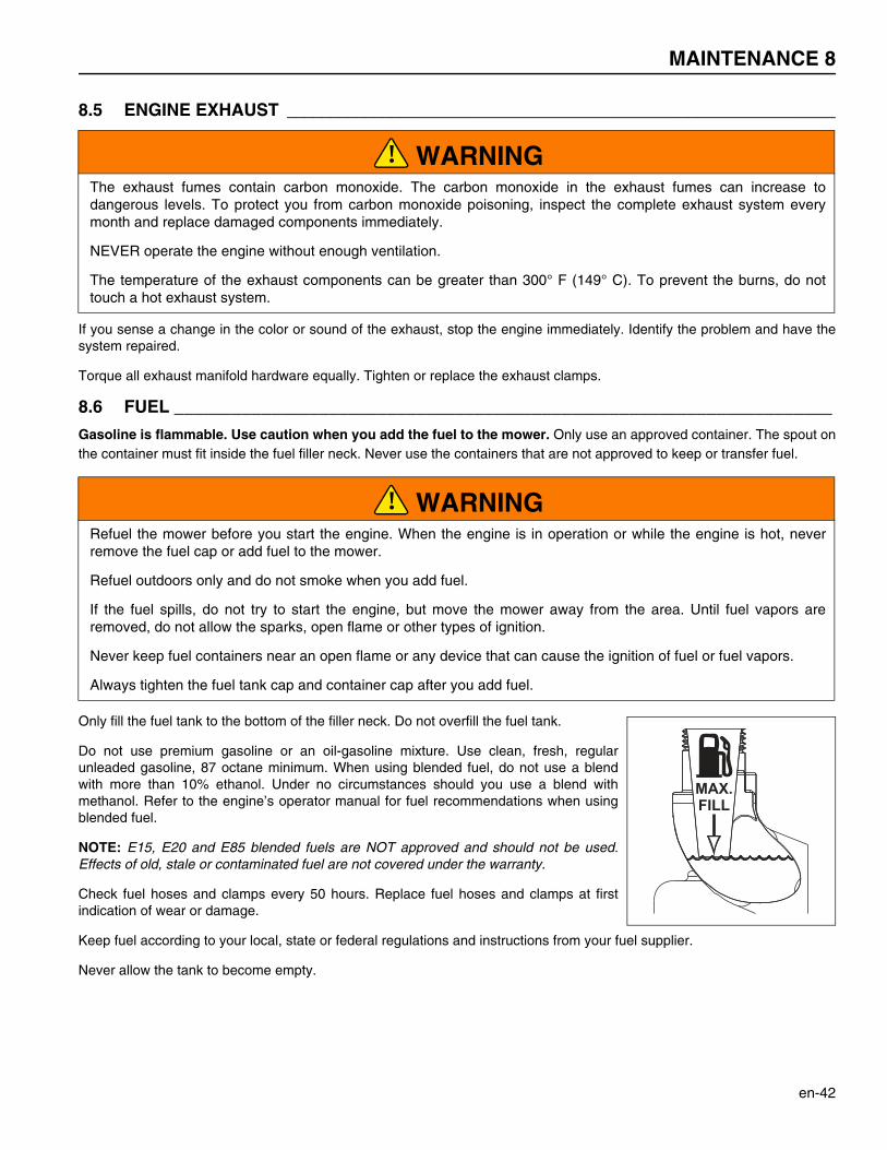
Only fill the fuel tank to the bottom of the filler neck. Do not overfill the fuel tank.
Do not use premium gasoline or an oil-gasoline mixture. Use clean, fresh, regularunleaded gasoline, 87 octane minimum. When using blended fuel, do not use a blendwith more than 10% ethanol. Under no circumstances should you use a blend withmethanol. Refer to the engine’s operator manual for fuel recommendations when usingblended fuel.
NOTE: E15, E20 and E85 blended fuels are NOT approved and should not be used.Effects of old, stale or contaminated fuel are not covered under the warranty.
Check fuel hoses and clamps every 50 hours. Replace fuel hoses and clamps at firstindication of wear or damage.
Keep fuel according to your local, state or federal regulations and instructions from your fuel supplier.
Never allow the tank to become empty.
WARNINGThe exhaust fumes contain carbon monoxide. The carbon monoxide in the exhaust fumes can increase todangerous levels. To protect you from carbon monoxide poisoning, inspect the complete exhaust system everymonth and replace damaged components immediately.
NEVER operate the engine without enough ventilation.
The temperature of the exhaust components can be greater than 300° F (149° C). To prevent the burns, do nottouch a hot exhaust system.
WARNINGRefuel the mower before you start the engine. When the engine is in operation or while the engine is hot, neverremove the fuel cap or add fuel to the mower.
Refuel outdoors only and do not smoke when you add fuel.
If the fuel spills, do not try to start the engine, but move the mower away from the area. Until fuel vapors areremoved, do not allow the sparks, open flame or other types of ignition.
Never keep fuel containers near an open flame or any device that can cause the ignition of fuel or fuel vapors.
Always tighten the fuel tank cap and container cap after you add fuel.
!
!

8 MAINTENANCE
en-43
8.7 TIRES ___________________________________________________________________
Keep the tires correctly inflated to increase tire life. Inspect the tread wear.
Check the tire pressure each day, while the tires are cool. Use an accurate low-pressure tire gauge.
Keep the rear tires inflated to 8-10 psi (0.55-0.69 BAR). Keep the front tires inflated to 12-15 psi (0.83-1.03 BAR).
8.8 WHEEL MOUNTING PROCEDURE ____________________________________________
Remove dirt, grease and oil from the stud threads. Do not lubricate threads.
Put the wheel on the hub. Inspect the wheel to make sure of full contact between surface of wheel and hub.
Tighten all hardware with your fingers, then torque hardware in a criss-cross order. When possible, tighten nuts in the topposition.
Check and torque hardware each day until torque is kept at 65-75 ft.lb. (88-102 Nm).
8.9 CHARGE THE BATTERY __________________________________________________________
Read the battery charger manual for specified instructions on the operation of the charger. Do not charge the battery with theignition switch in the ON position. Always disconnect the negative battery cable when charging the battery.
When possible, remove the battery from the mower before you charge the battery. If the battery is not sealed, check andmake sure the level of the electrolyte is above the plates in all of the cells.
Make sure the battery charger is turned OFF, then connect the battery charger to the battery terminals as specified in thebattery charger manual.
Always turn OFF the battery charger before you disconnect the battery charger from the battery terminals.
CAUTIONDO NOT try to put a tire on a rim unless you have the correct training, tools and experience. Incorrect mounting cancause an explosion which can cause injury.
WARNINGMake sure the mower is parked on a solid and level surface. Never work on a mower that is supported only by thejack. Always use jack stands.
If only the front or behind the mower is lifted, put the chocks in front of and behind the wheels that are not lifted.
WARNINGCharge the battery in an area with good airflow. The battery can release hydrogen gas that is explosive. To preventan explosion, keep any device that can cause sparks or flames away from the battery.
When the battery charger is turned on, to prevent injury, stay away from the battery. A battery that is damaged cancause an explosion.
!
!
!

MAINTENANCE 8
en-44
8.10 BATTERY ________________________________________________________________
Before you service the battery, make sure the ignition switch is in the OFF position and the key is removed.
Tighten the battery cables on the battery terminals, To prevent corrosion, apply a layer of silicone dielectric grease to batteryterminals and ends of cables. Keep the vent caps and battery terminal covers in position.
Before you do any welding operation on the mower, always disconnect the battery cables from the battery and the connectorsfrom the controllers.
Confirm the battery polarity before you connect or you disconnect the battery cables. Do not allow the battery cables to touchopposing terminals. Never start the engine with loose battery cables or disconnect the battery cables with the engine inoperation
When you install the battery, always connect the positive (RED) battery cable before the negative (BLACK) battery cable.
When you remove the battery, always disconnect the negative (BLACK) battery cable before the positive (RED) battery cable.
Jump-Starting the Mower
a Before you try to jump-start the mower, check the condition of the drained battery. Never use a quick charger to startthe engine.
b Connect the positive (+) battery terminal of the charged battery to positive battery terminal of the drained battery.
c Connect the negative (–) battery terminal of the charged battery to frame of vehicle with the drained battery.
d When the cables are connected, start the engine on the vehicle with the good battery, then start the mower.
CAUTIONWhen you service the battery, always use the tools with insulation, wear protective glasses and protective clothing.
Discard used batteries as shown in your local regulations.
WARNINGThe battery contains corrosive acid. Prevent contact with the battery acid.
Always wash your hands after you service a battery.
WARNINGThe battery posts, battery terminals and related accessories contain lead and lead compounds, chemicals known tothe State of California to cause cancer and other reproductive harm.
NOTICEFor EFI Engine: We recommend that the battery be disconnected, recharged with a battery charger and then testedfor full capacity. Jump-starting can damage other components on the engine.
WARNINGThe battery can release hydrogen gas that is explosive. To decrease the risk of an explosion, prevent sparks nearthe battery. Always connect the negative jumper cable to the frame of the mower with the drained battery.
!
!
!
!
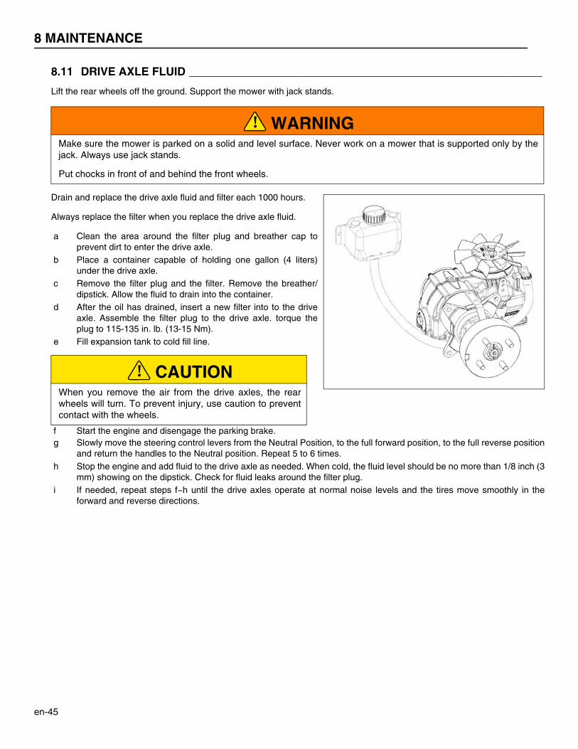
8 MAINTENANCE
en-45
8.11 DRIVE AXLE FLUID ________________________________________________________
Lift the rear wheels off the ground. Support the mower with jack stands.
Drain and replace the drive axle fluid and filter each 1000 hours.
Always replace the filter when you replace the drive axle fluid.
a Clean the area around the filter plug and breather cap toprevent dirt to enter the drive axle.
b Place a container capable of holding one gallon (4 liters)under the drive axle.
c Remove the filter plug and the filter. Remove the breather/dipstick. Allow the fluid to drain into the container.
d After the oil has drained, insert a new filter into to the driveaxle. Assemble the filter plug to the drive axle. torque theplug to 115-135 in. lb. (13-15 Nm).
e Fill expansion tank to cold fill line.
f Start the engine and disengage the parking brake. g Slowly move the steering control levers from the Neutral Position, to the full forward position, to the full reverse position
and return the handles to the Neutral position. Repeat 5 to 6 times. h Stop the engine and add fluid to the drive axle as needed. When cold, the fluid level should be no more than 1/8 inch (3
mm) showing on the dipstick. Check for fluid leaks around the filter plug. i If needed, repeat steps f~h until the drive axles operate at normal noise levels and the tires move smoothly in the
forward and reverse directions.
WARNINGMake sure the mower is parked on a solid and level surface. Never work on a mower that is supported only by thejack. Always use jack stands.
Put chocks in front of and behind the front wheels.
CAUTIONWhen you remove the air from the drive axles, the rearwheels will turn. To prevent injury, use caution to preventcontact with the wheels.
!
!

MAINTENANCE 8
en-46
8.12 FOLDING ROPS ___________________________________________________________
A folding Roll Over Protective Structure (ROPS) is included with this mower. Inspect the ROPS periodically for loosehardware or damage.
Every 400 hours, inspect the seat, seat belt, ROPS mounting hardware and ROPS frame for damage. Replace all damagedparts immediately. All replacement parts for the ROPS must be as specified in the Parts Manual.
Check and torque all ROPS hardware every 100 hours.
Only operate the mower with the ROPS in the folded position on flat and level surfaces. Do not operate the mower with theROPS in the folded position on the slopes, near sharp edges or near water. There is no roll over protection with the ROPSin the folded position.
Folding the ROPS.
a Remove the hair pin and ROPS pin from both sides of the ROPS. b Fold the ROPS toward the back of the mower. c Assemble the ROPS pin and hair pin to lock the ROPS in the folded
position. Never wear the seat belt with the ROPS in the folded position.
CAUTIONKeep the ROPS hardware correctly fastened. Do not do welding operations, drill, change or bend the ROPS.Replace damaged ROPS. Do not try to correct a damaged ROPS.
WARNINGTo prevent injury when you fold the ROPS, use caution to prevent yourfingers crushed between moving and rigid parts of the ROPS.
Always wear the set belt with the ROPS frame in the vertical and lockedposition.
Never wear the seat belt with the ROPS in the folded position.
Never operate without ROPS Pin being utilized
!
Folded Position
ROPSPin
Hair Pin
Vertical Position
ROPSPin
Hair Pin!
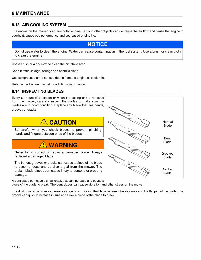
8 MAINTENANCE
en-47
8.13 AIR COOLING SYSTEM ____________________________________________________
The engine on the mower is an air-cooled engine. Dirt and other objects can decrease the air flow and cause the engine tooverheat, cause bad performance and decreased engine life.
Use a brush or a dry cloth to clean the air intake area.
Keep throttle linkage, springs and controls clean.
Use compressed air to remove debris from the engine oil cooler fins.
Refer to the Engine manual for additional information.
8.14 INSPECTING BLADES _____________________________________________________
Every 50 hours of operation or when the cutting unit is removedfrom the mower, carefully inspect the blades to make sure theblades are in good condition. Replace any blade that has bends,grooves or cracks.
A bent blade can have a small crack that can increase and cause apiece of the blade to break. The bent blades can cause vibration and other stress on the mower.
The dust or sand particles can wear a dangerous groove in the blade between the air vanes and the flat part of the blade. Thegroove can quickly increase in size and allow a piece of the blade to break.
NOTICEDo not use water to clean the engine. Water can cause contamination in the fuel system. Use a brush or clean clothto clean the engine.
CAUTIONBe careful when you check blades to prevent pinchinghands and fingers between ends of the blades.
WARNINGNever try to correct or repair a damaged blade. Alwaysreplaced a damaged blade.
The bends, grooves or cracks can cause a piece of the bladeto become loose and be discharged from the mower. Thebroken blade pieces can cause injury to persons or propertydamage.
Normal Blade
Bent Blade
Grooved Blade
Cracked Blade
!
!
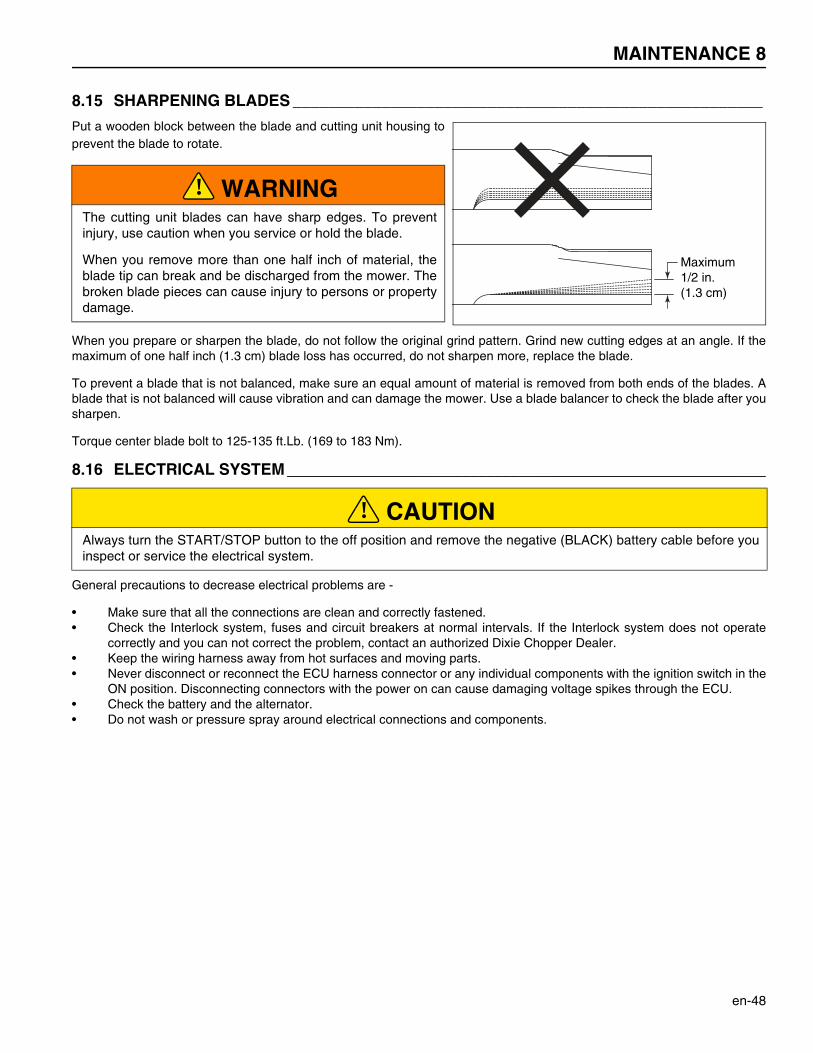
MAINTENANCE 8
en-48
8.15 SHARPENING BLADES _____________________________________________________
Put a wooden block between the blade and cutting unit housing toprevent the blade to rotate.
When you prepare or sharpen the blade, do not follow the original grind pattern. Grind new cutting edges at an angle. If themaximum of one half inch (1.3 cm) blade loss has occurred, do not sharpen more, replace the blade.
To prevent a blade that is not balanced, make sure an equal amount of material is removed from both ends of the blades. Ablade that is not balanced will cause vibration and can damage the mower. Use a blade balancer to check the blade after yousharpen.
Torque center blade bolt to 125-135 ft.Lb. (169 to 183 Nm).
8.16 ELECTRICAL SYSTEM ____________________________________________________________
General precautions to decrease electrical problems are -
• Make sure that all the connections are clean and correctly fastened.• Check the Interlock system, fuses and circuit breakers at normal intervals. If the Interlock system does not operate
correctly and you can not correct the problem, contact an authorized Dixie Chopper Dealer.• Keep the wiring harness away from hot surfaces and moving parts.• Never disconnect or reconnect the ECU harness connector or any individual components with the ignition switch in the
ON position. Disconnecting connectors with the power on can cause damaging voltage spikes through the ECU.• Check the battery and the alternator.• Do not wash or pressure spray around electrical connections and components.
WARNINGThe cutting unit blades can have sharp edges. To preventinjury, use caution when you service or hold the blade.
When you remove more than one half inch of material, theblade tip can break and be discharged from the mower. Thebroken blade pieces can cause injury to persons or propertydamage.
CAUTIONAlways turn the START/STOP button to the off position and remove the negative (BLACK) battery cable before youinspect or service the electrical system.
Maximum1/2 in.(1.3 cm)
!
!
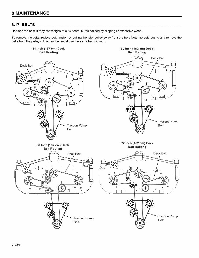
8 MAINTENANCE
en-49
8.17 BELTS __________________________________________________________________
Replace the belts if they show signs of cuts, tears, burns caused by slipping or excessive wear.
To remove the belts, reduce belt tension by pulling the idler pulley away from the belt. Note the belt routing and remove thebelts from the pulleys. The new belt must use the same belt routing.
Traction Pump Belt
Deck Belt
60 Inch (152 cm) DeckBelt Routing
72 Inch (182 cm) DeckBelt Routing
Traction Pump Belt
Deck Belt
66 Inch (167 cm) DeckBelt Routing
Deck Belt
Traction Pump Belt
Traction Pump Belt
Deck Belt
54 Inch (137 cm) DeckBelt Routing
MAINTENANCE 8
en-50
8.18 CARE AND CLEANING _____________________________________________________
Clean the mower and cutting units after each use. To prevent damage to the engine, do not wash the mower with the enginein operation. When possible, clean the mower with compressed air.
Use compressed air to clean the engine and the engine oil cooler fins. Do not pressure wash the engine.
Use clean water to wash your equipment.
Do not spray water at the control panel, ignition switch or other electrical components.
Clean all plastic or rubber parts with a weak soap solution or use commercially available rubber cleaners.
Repair damaged metal surfaces and use Dixie Chopper touch-up paint. Apply wax to the equipment for maximum paintprotection.
NOTICEDo not wash any part of the mower that is hot. Do not use the high-pressure spray or steam. Use cold water andautomotive cleaners.
NOTICETo use salt water or drain water is known to cause rust and corrosion of metal parts and can cause damage orfailure. This damage is not included by the factory warranty.
CAUTIONTo prevent fire, clean grass clippings and dirt from the cutting unit, drives, engine and exhaust components.
WARNINGNever use your hands to clean cutting units. Use a brush to remove grass clippings from the blades. The blades aresharp and can cause injuries.
!
!

8 MAINTENANCE
en-51
8.19 MOWER STORAGE ________________________________________________________
General
• Clean the mower and lubricate. Repair and paint damaged or open metal.• Inspect the mower, tighten all hardware, replace worn or damaged components.• Clean the tires and keep the mower so that the load is not on the tires. If the mower is not on the jack stands, check
tires at normal intervals and add air when needed.• Keep the mower and all accessories clean, dry and protected from the elements. Never keep the mower near an open
flame or spark which can cause ignition of the fuel or fuel vapors.
Battery
• Remove, clean and keep the battery in the upright position on a surface that is not metal in a cool dry location. Toprevent increased battery discharge, do not keep the battery on a metal surface.
• Check and charge the battery every 60 to 90 days.• Keep the battery in a cool dry location. To decrease the self discharge rate, the temperature must not be more than 80°
F (27° C) or less than 20° F (-7° C).
Engine
• Change the engine oil and filter.• Clean the outside surface of the engine. Paint bare metal or apply a thin layer of rust preventative oil.• Add a fuel stabilizer to prevent the fuel to become stale. See your fuel supplier for instructions. Start the engine.
Operate the engine for two minutes to circulate the stabilizer throughout the fuel system.
Cutting Units
• Completely clean the cutting units. Repair and paint any damaged or bare metal surfaces.• Lubricate all grease fittings and friction points.• Apply a thin layer of rust preventative oil to the sharpened edges of the blades.
After Storage
• Check and install the battery. If necessary, charge the battery.• Check or service the fuel filter and air cleaner• Check the level of engine oil and drive axle fluid.• Fill the fuel tank with fuel.• Make sure the tires are correctly inflated.• Remove all oil from the blades.• Start the engine at 1/2 throttle. Allow the engine to become warm and lubricated.
CAUTIONThe cutting unit blades can have sharp edges. To prevent injury, use caution when you service or hold the blade.
WARNINGNever operate the engine without enough ventilation or in an enclosed area. The carbon monoxide in the exhaustfumes can increase to dangerous levels.
!
!
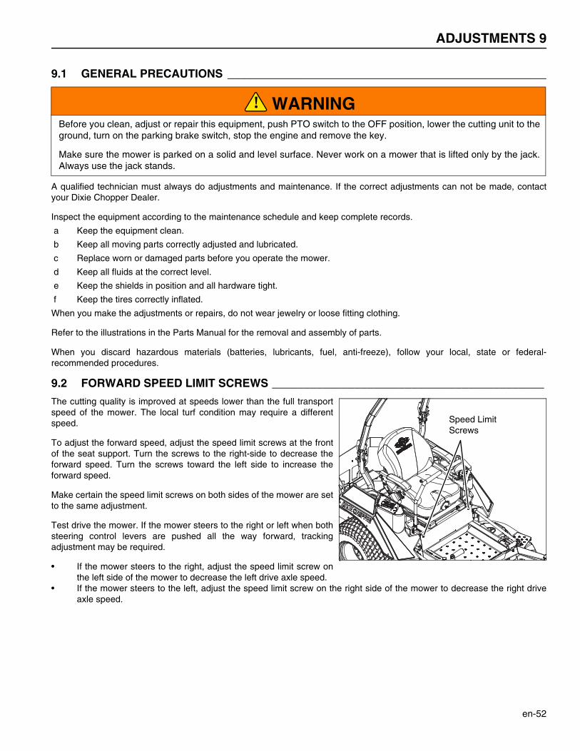
ADJUSTMENTS 9
en-52
9Adjustments
9.1 GENERAL PRECAUTIONS ________________________________________________________
A qualified technician must always do adjustments and maintenance. If the correct adjustments can not be made, contactyour Dixie Chopper Dealer.
Inspect the equipment according to the maintenance schedule and keep complete records.
a Keep the equipment clean.
b Keep all moving parts correctly adjusted and lubricated.
c Replace worn or damaged parts before you operate the mower.
d Keep all fluids at the correct level.
e Keep the shields in position and all hardware tight.
f Keep the tires correctly inflated.
When you make the adjustments or repairs, do not wear jewelry or loose fitting clothing.
Refer to the illustrations in the Parts Manual for the removal and assembly of parts.
When you discard hazardous materials (batteries, lubricants, fuel, anti-freeze), follow your local, state or federal-recommended procedures.
9.2 FORWARD SPEED LIMIT SCREWS ___________________________________________
The cutting quality is improved at speeds lower than the full transportspeed of the mower. The local turf condition may require a differentspeed.
To adjust the forward speed, adjust the speed limit screws at the frontof the seat support. Turn the screws to the right-side to decrease theforward speed. Turn the screws toward the left side to increase theforward speed.
Make certain the speed limit screws on both sides of the mower are setto the same adjustment.
Test drive the mower. If the mower steers to the right or left when bothsteering control levers are pushed all the way forward, trackingadjustment may be required.
• If the mower steers to the right, adjust the speed limit screw onthe left side of the mower to decrease the left drive axle speed.
• If the mower steers to the left, adjust the speed limit screw on the right side of the mower to decrease the right driveaxle speed.
WARNINGBefore you clean, adjust or repair this equipment, push PTO switch to the OFF position, lower the cutting unit to theground, turn on the parking brake switch, stop the engine and remove the key.
Make sure the mower is parked on a solid and level surface. Never work on a mower that is lifted only by the jack.Always use the jack stands.
!
Speed Limit Screws
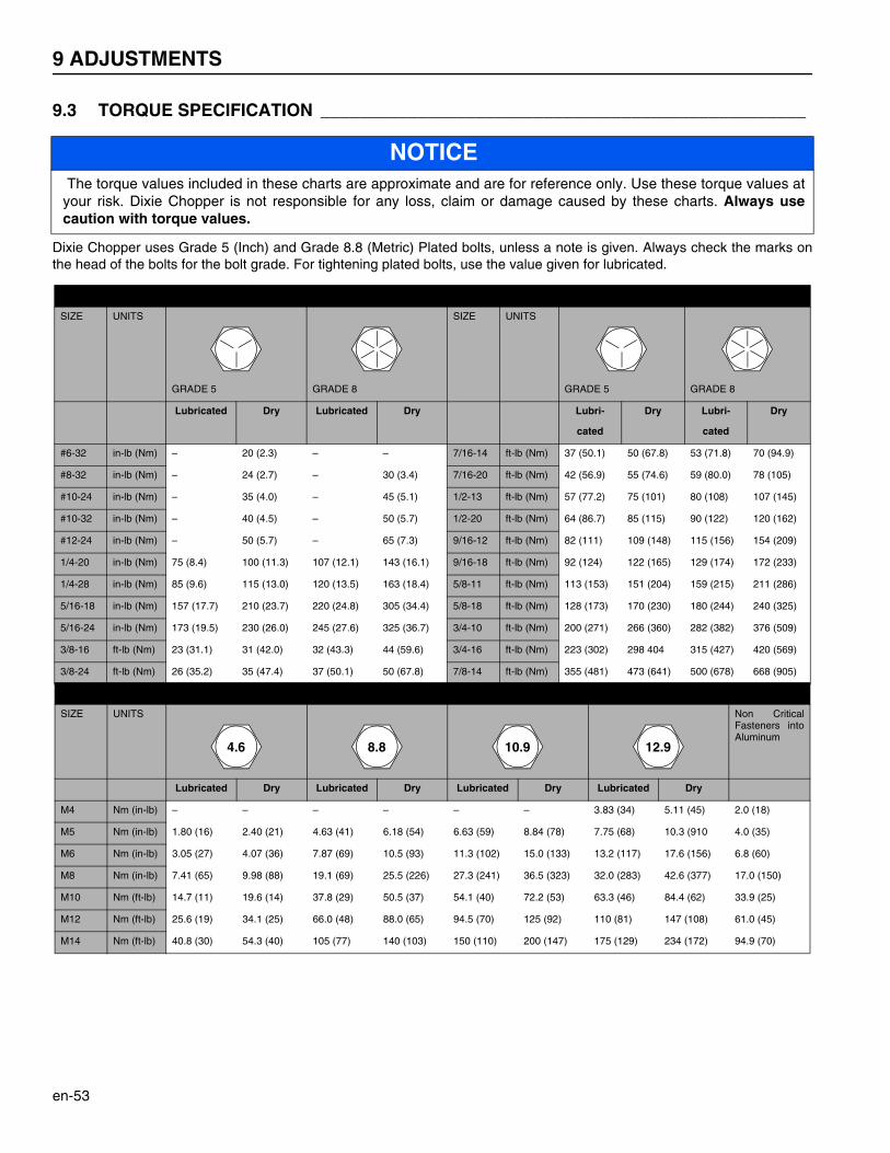
9 ADJUSTMENTS
en-53
9.3 TORQUE SPECIFICATION __________________________________________________
Dixie Chopper uses Grade 5 (Inch) and Grade 8.8 (Metric) Plated bolts, unless a note is given. Always check the marks onthe head of the bolts for the bolt grade. For tightening plated bolts, use the value given for lubricated.
NOTICE The torque values included in these charts are approximate and are for reference only. Use these torque values atyour risk. Dixie Chopper is not responsible for any loss, claim or damage caused by these charts. Always usecaution with torque values.
AMERICAN NATIONAL STANDARD FASTENERS
SIZE UNITS
GRADE 5 GRADE 8
SIZE UNITS
GRADE 5 GRADE 8
Lubricated Dry Lubricated Dry Lubri-
cated
Dry Lubri-
cated
Dry
#6-32 in-lb (Nm) – 20 (2.3) – – 7/16-14 ft-lb (Nm) 37 (50.1) 50 (67.8) 53 (71.8) 70 (94.9)
#8-32 in-lb (Nm) – 24 (2.7) – 30 (3.4) 7/16-20 ft-lb (Nm) 42 (56.9) 55 (74.6) 59 (80.0) 78 (105)
#10-24 in-lb (Nm) – 35 (4.0) – 45 (5.1) 1/2-13 ft-lb (Nm) 57 (77.2) 75 (101) 80 (108) 107 (145)
#10-32 in-lb (Nm) – 40 (4.5) – 50 (5.7) 1/2-20 ft-lb (Nm) 64 (86.7) 85 (115) 90 (122) 120 (162)
#12-24 in-lb (Nm) – 50 (5.7) – 65 (7.3) 9/16-12 ft-lb (Nm) 82 (111) 109 (148) 115 (156) 154 (209)
1/4-20 in-lb (Nm) 75 (8.4) 100 (11.3) 107 (12.1) 143 (16.1) 9/16-18 ft-lb (Nm) 92 (124) 122 (165) 129 (174) 172 (233)
1/4-28 in-lb (Nm) 85 (9.6) 115 (13.0) 120 (13.5) 163 (18.4) 5/8-11 ft-lb (Nm) 113 (153) 151 (204) 159 (215) 211 (286)
5/16-18 in-lb (Nm) 157 (17.7) 210 (23.7) 220 (24.8) 305 (34.4) 5/8-18 ft-lb (Nm) 128 (173) 170 (230) 180 (244) 240 (325)
5/16-24 in-lb (Nm) 173 (19.5) 230 (26.0) 245 (27.6) 325 (36.7) 3/4-10 ft-lb (Nm) 200 (271) 266 (360) 282 (382) 376 (509)
3/8-16 ft-lb (Nm) 23 (31.1) 31 (42.0) 32 (43.3) 44 (59.6) 3/4-16 ft-lb (Nm) 223 (302) 298 404 315 (427) 420 (569)
3/8-24 ft-lb (Nm) 26 (35.2) 35 (47.4) 37 (50.1) 50 (67.8) 7/8-14 ft-lb (Nm) 355 (481) 473 (641) 500 (678) 668 (905)
METRIC FASTENERS
SIZE UNITS Non CriticalFasteners intoAluminum
Lubricated Dry Lubricated Dry Lubricated Dry Lubricated Dry
M4 Nm (in-lb) – – – – – – 3.83 (34) 5.11 (45) 2.0 (18)
M5 Nm (in-lb) 1.80 (16) 2.40 (21) 4.63 (41) 6.18 (54) 6.63 (59) 8.84 (78) 7.75 (68) 10.3 (910 4.0 (35)
M6 Nm (in-lb) 3.05 (27) 4.07 (36) 7.87 (69) 10.5 (93) 11.3 (102) 15.0 (133) 13.2 (117) 17.6 (156) 6.8 (60)
M8 Nm (in-lb) 7.41 (65) 9.98 (88) 19.1 (69) 25.5 (226) 27.3 (241) 36.5 (323) 32.0 (283) 42.6 (377) 17.0 (150)
M10 Nm (ft-lb) 14.7 (11) 19.6 (14) 37.8 (29) 50.5 (37) 54.1 (40) 72.2 (53) 63.3 (46) 84.4 (62) 33.9 (25)
M12 Nm (ft-lb) 25.6 (19) 34.1 (25) 66.0 (48) 88.0 (65) 94.5 (70) 125 (92) 110 (81) 147 (108) 61.0 (45)
M14 Nm (ft-lb) 40.8 (30) 54.3 (40) 105 (77) 140 (103) 150 (110) 200 (147) 175 (129) 234 (172) 94.9 (70)
4.6 8.8 10.9 12.9
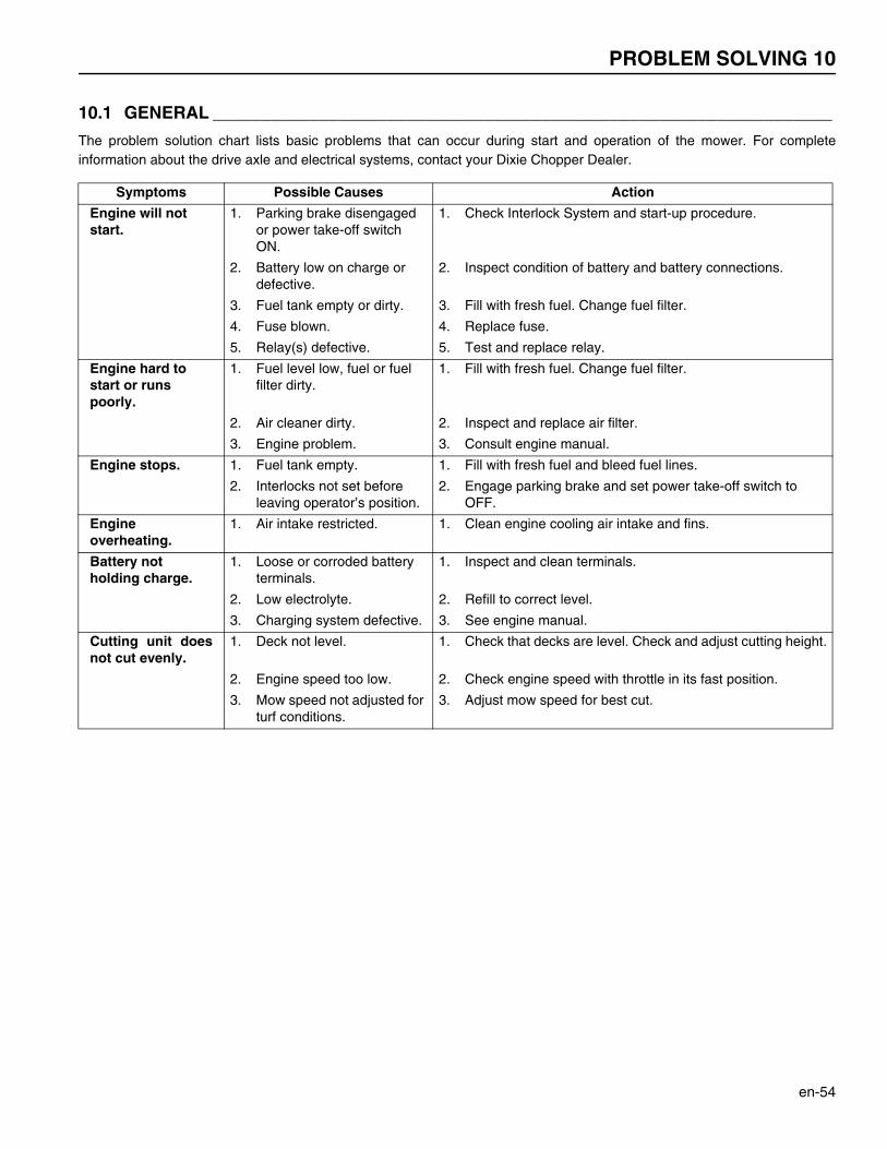
PROBLEM SOLVING 10
en-54
10Problem Solving
10.1 GENERAL ________________________________________________________________
The problem solution chart lists basic problems that can occur during start and operation of the mower. For completeinformation about the drive axle and electrical systems, contact your Dixie Chopper Dealer.
Symptoms Possible Causes Action
Engine will not start.
1. Parking brake disengaged or power take-off switch ON.
1. Check Interlock System and start-up procedure.
2. Battery low on charge or defective.
2. Inspect condition of battery and battery connections.
3. Fuel tank empty or dirty. 3. Fill with fresh fuel. Change fuel filter.
4. Fuse blown. 4. Replace fuse.
5. Relay(s) defective. 5. Test and replace relay.
Engine hard to start or runs poorly.
1. Fuel level low, fuel or fuel filter dirty.
1. Fill with fresh fuel. Change fuel filter.
2. Air cleaner dirty. 2. Inspect and replace air filter.
3. Engine problem. 3. Consult engine manual.
Engine stops. 1. Fuel tank empty. 1. Fill with fresh fuel and bleed fuel lines.
2. Interlocks not set before leaving operator’s position.
2. Engage parking brake and set power take-off switch to OFF.
Engine overheating.
1. Air intake restricted. 1. Clean engine cooling air intake and fins.
Battery not holding charge.
1. Loose or corroded battery terminals.
1. Inspect and clean terminals.
2. Low electrolyte. 2. Refill to correct level.
3. Charging system defective. 3. See engine manual.
Cutting unit doesnot cut evenly.
1. Deck not level. 1. Check that decks are level. Check and adjust cutting height.
2. Engine speed too low. 2. Check engine speed with throttle in its fast position.
3. Mow speed not adjusted for turf conditions.
3. Adjust mow speed for best cut.

10 PROBLEM SOLVING
en-55
10.2 EAGLE HP MODEL FAULT CODES ___________________________________________
When a fault is detected by the display panel, it is displayed on the LCD display as a numeric code. Below is a chart of theerror codes and potential sources.
Fault Code Description
10 Continuous PTO clutch current too high – check PTO clutch coil resistance.
11 Function inhibited because continuous system current too high.
12 Check battery condition and connections, check starter solenoid wiring for shorts.
13 Check battery condition and connections, check PTO and PTO wiring for shorts.
14 Check battery condition and connections, check fuel solenoid and fuel solenoid wiring for shorts.
15 Check headlight wiring for shorts.
16 Check battery condition and connections, check deck motor and wiring for shorts.
17 Check battery condition and connections.
18 Check battery condition and connections, check starter and fuel solenoid connections for shorts.
19 Check battery condition and connections, check PTO and PTO wiring for shorts.
20 Check battery connections, check fuel solenoid and wiring for shorts.
21 Check battery connections, check headlight wiring for shorts.
22 Check battery condition and connections, check deck motor and wiring for shorts.
23 Check battery condition and connections, check all wiring for shorts.
24 Excessive system current.
25 Check PTO current.
26 Excessive system current.
27 Excessive system current, check headlight.
28 Excessive system current, check for binding deck lift or problem with motor.
29 Excessive system current.
30 Console internal fault.
39 Console internal fault, some or all power functions inhibited.
40 Console internal fault.


Dixie Chopper is a registered trademark of Jacobsen Professional Lawn Care Inc.any and all use and/or reproductions are strictly prohibited.
DIXIE CHOPPER6302 E. County Road 100 N.Coatesville, Indiana 46121
www.dixiechopper.com
Printed In USA