2017 Toronto Canada Symposium on Simulation for...
9
Toronto Canada 2017 2017 Proceedings of the Symposium on Simulation for Architecture and Urban Design Edited by Michela Turrin Brady Peters William O’Brien Rudi Stouffs Timur Dogan
Transcript of 2017 Toronto Canada Symposium on Simulation for...

Toronto Canada
2017
2017 Proceedings of theSymposium on Simulation for Architecture and Urban Design
Edited byMichela TurrinBrady PetersWilliam O’BrienRudi StouffsTimur Dogan
Sym
po
sium
on
Sim
ulat
ion
for
Arc
hite
ctur
e an
d U
rban
Des
ign
2017
Sym
po
sium o
n Sim
ulation fo
r Architecture and
Urb
an Desig
n2017 P
roceedings of the
8887867813659
ISBN 978-1-365-88878-690000

225
Hybrid Workstations: Establishing Interactive and Responsive User-Interfaces for Daylight Applications
Emad Al-Qattan, Liliana Beltrán and Wei Yan
Texas A&M University College Station, TX, USA {emadkkqattan, lbeltran,
wyan}@tamu.edu
ABSTRACT The research project presented in this paper explores the benefits of utilizing a hybrid workstation in a daylight design application. The prototype developed for this work links a physical design object with digital modeling and simulation tools. The aim of the work is to integrate physical and material properties of kinetic design objects in the digital workflow. Additionally, the hybrid system utilizes smart hand-held devices to provide designers with a user-friendly interface to control modeling parameters. The developed workstation provides real-time interactive features and live responses to visualize and evaluate design options in both the digital and physical environments. The proposed work demonstrates unique possibilities for daylight applications, which will assist designers in making informed decisions regarding both the aesthetics and the performance of a kinetic architectural system.
Author Keywords Parametric Design; Human-Computer Interaction; Daylight Design, Ubiquitous Computing; Physical Computing.
ACM Classification Keywords B.7.1 TYPES AND DESIGN STYLES (Input/output Circuits); B.7.2 Design Aids (Simulation); C.5.3 MICROCOMPUTERS (Portable Devices, Workstations); I.2.9 ROBOTICS (Kinematics and Dynamics); H.1.2 USER/MACHINE SYSTEMS;
1 INTRODUCTION Currently, architects are challenged to seek alternative design solutions to meet climatic and social changes. Research has shown that architectural elements with kinetic capabilities (e.g. façade, shading, etc.) may provide a solution to address such conditions in addition to their stimulating visual appearance [6].
Existing works investigating kinetic architectural elements span from geometric studies to software tool development. A drawback in conventional digital workflows is the separation between physical studies, CAD implementation, and simulation procedures [11]. Conversely, the work included in this paper attempts to establish and utilize hybrid workflows to address the gap between design tasks
through linking physical and digital design objects together. A design object in the context of this work refers to the digital and physical representations of an architectural element.
The research further investigates hybrid workflows with the aim to enhance the users’ interactive experience when manipulating geometry and conducting simulation studies. The work involves integrating smart hand-held devices to provide designers with a customizable and an intuitive interface to control modeling parameters. The hybrid workstation will assist designers in relating physical geometry with digital simulation results, which will provide them with the means to comprehend the complexity associated with designing a kinetic architectural system for a daylight application.
A prototype is developed to test the proposed workflow; and it includes two main parts, the artifact, and the digital environment. The artifact consists of a physical design object and a Physical Computing system. The physical computing system is broadly defined as the platform to communicate between both the digital and physical environments; and it is composed of sensors, actuators, and microcontrollers [9]. The digital environment consists of a 3D modeler, a visual programming environment, and a daylight simulation engine (Figure 1). The link created between the system’s components is established through visual programming, which uses a wireless Local Area Network (LAN) for data communication. The work will enable designers to control and manage computational tasks using an everyday, personal, and convenient device.
Figure 1. Hybrid Workstation, artifact (left) linked to a digital
parametric model (right).
SimAUD 2017 May 22-24 Toronto, Canada © 2017 Society for Modeling & Simulation International (SCS)

226
2 RESEARCH CONTEXT AND RELATED WORKS The proposed hybrid workflow is considered as a Mixed Reality (MR) approach in design. The notion of MR can be illustrated as a linear spectrum that is defined by two ends; the virtual environment at one end and the real environment at the other [8]. However, real-time interaction and live responses provided by the proposed hybrid workstation aligns with the notion of embodiment where the two ends of the MR spectrum meet to create a loop [2,12].
Earlier works included in this paper demonstrate a few of the many attempts to develop and investigate kinetic elements for addressing environmental design issues; which involve creating computational workflows, hybrid workstations, and software tool improvements. Each of the following examples discussed below highlights an essential component in a hybrid workflow, which will help in informing the progress of the proposed work.
The experiment by ElGhazi and Mahmoud investigates kinetic origami patterns for creating a façade shading element. The work involves conducting physical studies as well as digital simulations [3]. Models of the kinetic unit were physically made and folded. The geometry’s response provided an understanding of its physical behavior. Afterwards, the unit, and its folding motion, were recreated in the digital environment for conducting daylight simulations. The experiment demonstrates the value of physical studies in visualizing and realizing an object’s kinetic features. Nevertheless, the work shows a linear process where digital and physical workflows are separated.
Another experiment by Kensek involves establishing hybrid workflows for studying the environmental impact on BIM models [7]. The work consists of a digital architectural model and an artifact. The workflow links Revit geometry with a physical computing system using Dynamo and the Revit API. Physical design objects are integrated with sensors that measure CO2, lighting, and humidity levels to activate geometric responses in both the digital and physical environments. The hybrid workflow also uses simulations to optimize design solutions. The use of environmental data with radiation analysis and optimization tools provide unique possibilities for studying kinetic object responses in a digital design workflow. Yet, further investigations of the kinematics involved in the study may provide insight for designers to understand geometric behavior (such as in the case of ElGhazi and Mahmoud) when utilizing such a method.
The work by Plotnikov et al. demonstrates a hybrid workstation with tangible capabilities that links physical forms with simulation tools to evaluate thermal comfort and vision in an urban setting. [11]. The work demonstrates real-time interaction and digital feedback, and an approach to associate physical geometry with digital geometric and non-geometric information. The work demonstrates a high-level integration of software tools to assist designer in their work. Yet, the experiment demonstrates a unidirectional
link; physical forms do not display actuation (such as in the case of Kensek).
3 RESEARCH CLAIM AND SIGNIFICANCE Current research shows the different methods to bridge between the digital and physical environments: including patterns studies, form optimization, and urban planning. The proposed work will suggest a hybrid workflow for designing and evaluating kinetic objects for daylighting in the aim of extending the exploration of these studies.
The proposed work will (1) integrate modeling and simulation tools together through a single visual programming workflow to improve designers work experience. Designers will navigate the visual program to perform the different tasks without the need to use multiple and separate applications. Additionally, integrating the tools in a single workflow will allow the designer to manage complex programming procedures through smart hand-held devices (phones, tablets, etc.), which will (2) help them to operate the system more intuitively for visualizing design options, transforming geometry, and controlling modeling parameters. The proposed work finds an opportunity in utilizing the computing capabilities and the customizable interface of smart hand-held devices in this research, as they provide new possibilities for digital design applications.
In summary, the proposed hybrid workstation provides a straightforward approach for users and novice programmers to interact with digital models thought the integration of portable devices in the design process. The hybrid workstation will allow for real-time interaction, and live physical and digital feedback. associating physical qualities of kinetic systems (geometry, motion, and materials) with digital simulation readings.
4 RESEARCH METHOD A prototype of the hybrid workstation is developed to test the proposed system. The process of creating the workstation is broken down in the following sections.
4.1 Criteria Selection The aim of this work is to design and evaluate a kinetic shading system that can block direct sun, diffuse sunlight, and control vision. The shading system in this experiment is represented as a vertical paneled shading system consisting of an array of 81 square panels that can rotate freely in 3D space. The criteria used for creating the work includes: (1) choosing the hybrid workstation’s type and theme, (2) panel geometry and kinematics, (3) project site, and (4) daylight simulation metrics.
Hornecker and Buur’s guidelines assist in the process of defining the purpose and audience of the proposed hybrid workstation [4]. The theme that best describes the proposed work is an expressive representation, which is defined by the following three points: (1) representational

227
significance, (2) externalization, and (3) perceived coupling. Expressive representation, design objects must provide value and clarity to the user. In this work, design objects provide different types of design information (haptic, visual, geometric, etc.), which together inform the design process. Externalization, design objects must be setup in the hybrid workstation to assist designers in their thinking process by providing them with visual and numeric feedback based on their interaction with the design objects. Perceived coupling, design objects in both environments must complement each other. Digital and physical information provided by the hybrid workstation must relate to each other to create a logical connection for the designer make sense of the system’s inputs and outputs.
Following in the process is selecting the geometry’s type of kinetic motion to meet the daylighting objectives set by the designer. In this experiment, rotation is chosen as the primary type of kinetic panel motion. Panels are created and programmed in both the artifact and digital model to flexibly rotate in all three axes in digital and physical space.
The hybrid workstation enables multiple data entries from users and the environment. The specific data types included in this work are: solar information (digital) and user input (panels’ angels of rotation). Users’ data is obtained through the smart hand-held device, which controls modeling and simulation parameters set in the digital environment.
4.2 Tools Software and hardware tools are categorized in four groups based on their application in the proposed workflow.
• Modeling: Rhino (3D modeler) and Grasshopper (a visual programming environment and plug-in for Rhino).
• Physical Computing system: TouchOSC (software application for smart hand-held devices and interface for data communication) [13], Arduino (a microcontroller board type MEGA 2560), servomotors (two high torque motors and two mini motors).
• Linkage: Firefly (software package and plug-in for Grasshopper) [10]. It is used to establish data communication between the physical computing system and 3D modeler.
• Simulation: Diva (daylight analysis plug-in for Grasshopper based on LEED v4, which uses Radiance as its simulation engine), and Ladybug (plug-in for Grasshopper to import .epw files and generate visualizations for environmental studies).
4.3 Digital Model A base-case model is created in Rhino (Figure 2) to test the proposed hybrid workflow. The digital model represents a generic space with a south-facing window. The models’ elements will be referenced later in Grasshopper to create the kinetic shading system and to perform the daylighting analysis.
Figure 2. Digital model created in Rhino, measurements are in feet.
4.4 Parametric workflow A visual programming workflow was created using Grasshopper to (1) integrate modeling and simulation tools, and (2) link the digital model, artifact, and smart hand-held device together. Figure 3 shows the programming logic created in Grasshopper for establishing the hybrid workflow.
Figure 3. Visual programming workflow in Grasshopper.
The color code used in Figure 3 defines two types of procedures: the first (white blocks) illustrates the common practice of modeling and simulation using Grasshopper or any other visual programming interface; the second (green blocks) illustrates the extended functionality proposed in this work.
The new addition enables the smart hand-held device to manage the hybrid system’s data inputs and outputs. The designer will be able to select specific types of geometry from the model, change parameters values, and display kinetic responses physically through the artifact. For
228
example, the designer can locate a panel in the digital array, display its rotation physically, and changing its angles of rotation in real-time in both models. The smart hand-held device is linked to Grasshopper through a wireless LAN using the TouchOSC application installed on the smart hand-held device.
The base-case’s geometry generated in Rhino is referenced in Grasshopper to create a parametric model to be used for generating the kinetic shading system (Figure 4). Afterwards, a relationship between the panels’ angle of rotation and the sun’s position was established. The parametric relationship will allow the sun to act as an attractor to rotate the panels. The system’s mechanical setup and the panels’ animated behavior will be further explained in the Kinematics and Behavior section.
Figure 4. Shading system generated with Grasshopper.
4.5 Artifact The hybrid workstation in this experiment uses a single physical panel to display the different kinetic responses. The aim of this work is not to physically replicate the shading system in its entirety, but to provide the designer with the means to evaluate an object’s physical properties (mechanical performance, material properties, geometry, etc.). Additionally, a single panel at this stage is cost effective and assists the designer to test the functionality of the proposed system. However, further development of the work will involve creating a larger array to help designers obtain a better understanding of a kinetic system’s behavior, mechanics, and overall performance in a daylight application. A CAD/CAM approach was adopted to create the artifact. The different components of the artifact (panel, supporting frame, joints, etc.) were designed and prepared in Rhino for laser cutting. The materials used for the artifact are: clear Acrylic for the artifact’s support and joints, and a silver coated cardboard with high reflectance for the panel (Figure 5).
Figure 5. Artifact with a single panel.
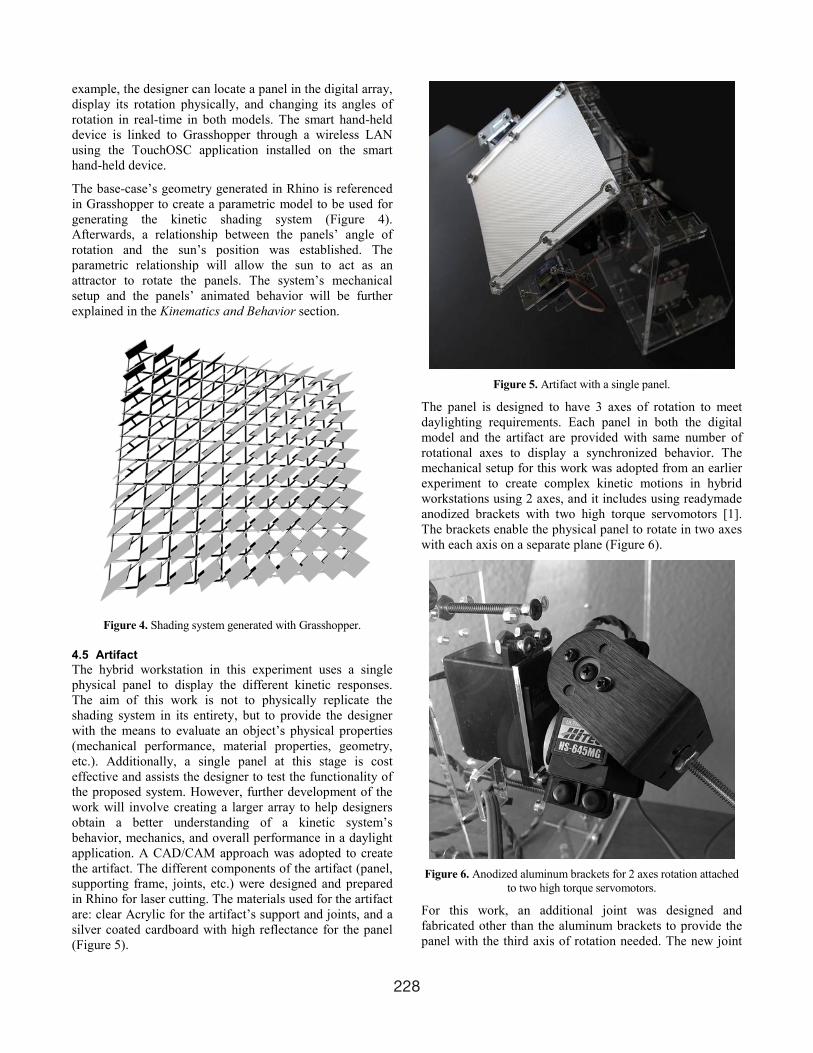
The panel is designed to have 3 axes of rotation to meet daylighting requirements. Each panel in both the digital model and the artifact are provided with same number of rotational axes to display a synchronized behavior. The mechanical setup for this work was adopted from an earlier experiment to create complex kinetic motions in hybrid workstations using 2 axes, and it includes using readymade anodized brackets with two high torque servomotors [1]. The brackets enable the physical panel to rotate in two axes with each axis on a separate plane (Figure 6).
Figure 6. Anodized aluminum brackets for 2 axes rotation attached
to two high torque servomotors.
For this work, an additional joint was designed and fabricated other than the aluminum brackets to provide the panel with the third axis of rotation needed. The new joint

229
is directly attached to the physical panel and uses two mini servomotors to rotate.
Servomotor 1 and 2 (Figure 7), are programmed to rotate the panel to track the sun. The motors will keep the panel’s surface perpendicular to the generated sunrays using Ladybug. Servomotor 3 and 4 are directly rotated by the OSC interface, which provides the designer with the option to personalize the shading system’s configuration and performance (visual appearance, light penetration, and vision).
Figure 7. Virtual planes (blue, magenta, and green) created in this view to show how the panel will rotate in physical space. The blue (YZ) and magenta (XZ) grids show the two planes of rotation used
to track the sun. As for the green (XZ) plane, it rotates the panel using the OSC interface.
4.6 Linkage and Control System The link between the artifact, digital model, and smart device is established through Firefly and a wireless LAN. The link will enable real-time communication and live feedback between all three components of the system. The TouchOSC application installed on the smart hand-held device will connect it to the visual program in Grasshopper using Firefly’s OSC node. OSC values (user data) received by Grasshopper are calibrated, and then sent to their corresponding modeling parameters and motors in the artifact. Parameter values communicated between the digital model and the artifact are angles of rotation.
Angles of rotation for Servomotor 1 and 2 are obtained from the digital panels’ position when tracking the sun, and are sent to the artifact through the computer’s USB port. Angles of rotation for Servomotors 3 and 4 are sent to both the digital model and artifact through the established wireless connection.
The smart device’s interface is designed using an OSC editor [13]. The interface is customized to include a range of modeling parameters in addition to angles of rotation values (Figure 8).
Figure 8. Interface created for the smart hand-held device for the
designer to control modeling parameters.
The designer can perform the following tasks using the OSC interface:
• Panel selection: select a panel from the array to physically display its rotation using the artifact (Figure 9).
• Solar information: set the hour, day, and month for conducting daylight analysis and for moving the sun along its path.
• Angles of rotation: send rotation values to Servomotor 3 and 4.
• Number of panels: modify the array by increasing or decreasing the number of its panels.
Figure 9. The panel selected through OSC interface will be
highlighted in the Rhino scene (panel in the lower row), and its rotation angles will be sent to the artifact automatically.
4.7 Kinematics and Behavior The Ladybug plug-in will import EnergyPlus weather files (.epw), which include site coordinates, temperature, radiation, solar information, etc. The suggested site for this project is located in College Station, TX, USA. Site coordinates obtained from Ladybug are used to generate a

230
3D sun path visualization in Rhino, which will be used to program the digital panels’ rotation. A point representing the sun’s position is generated on the path, which will be used in Grasshopper to create the attractor for rotating the panels.
The relationship between the panels and the sun provide the rotation angles for Servomotor 1 and 2. The process involves generating a vector between the center of the proposed site and the point representing the sun on the path. Afterwards, the vector is duplicated and centered on each panel’s surface in the array. In the digital model, each panel is reoriented to face the sun by having its Normal coincident to the duplicated vector. Figure 10 shows the panels rotating to track the sun from 9 AM to 5 PM.
Figure 10. Testing panel rotation between 9 AM and 5 PM, 21st of
August.
Angels of rotation values for each panel are not provided in the current Grasshopper program, because the relationship between the panels motion and the sun’s position on the path is automated. Therefore, an additional procedure was developed in the visual program to measure the Altitude and Azimuth angles for each panel using the duplicated vectors. The calculated angles are then calibrated to match the servomotors range of motion, and then sent to the artifact. Figure 11 (top and middle images) shows how the physical panel rotates when the sun position is changed in Grasshopper. The Altitude and Azimuth angle values are sent to their corresponding servomotors to display a synchronized behavior in both model.
Figure 11 (lower image) shows how the physical panel rotates using the smart hand-held device by having the user directly providing the angles of rotation for Servomotor 3 and 4. The third axis of rotation is restricted in motion between the angles of 120 to 150 degrees in both the digital and physical models. The aim is to avoid clashes between the panel and its supporting structure.
Figure 11. The hybrid workstation with all three components linked
with each other. Panel rotated to block direct sun at 2 PM, 21st of December (top image); Panel rotated to block direct sunlight at 11
AM on the same day (middle image); and smart device used to rotate the panels using the OSC dial (lower image).
5 SIMULATION The aim of the proposed work is to develop a workstation to bridge digital and physical environments together to design and evaluate kinetic objects intended for daylight applications. The prototyping process, previously discussed, explains the making of the workstation. This section will focus on integrating simulation tools with the proposed workflow. The use of daylight analysis tools in this experiment are not used to prove that a specific type of geometry or motion suggests an optimal solution for a daylight condition, it is rather meant to demonstrate the benefits of juxtaposing digital and physical information together to inform the designer’s decisions and process.
Ladybug, as previously mentioned, provides interactive visualizations and weather data used to construct the parametric features of the shading system. However, for simulation purposes Diva for Grasshopper is used to
231
conduct the analysis. Diva’s analysis procedures and metrics are setup and accessed through the visual program. For this work, a Climate-Based analysis is used; Grid-based with two feet spacing and a minimum illuminance of 300 lux. Material setup for the base-case objects are selected from the predefined material library provided by Diva: ceiling (GenericCeiling_70), walls (GenericWall_50), floor (GenericFloor_20), window (Glazing_SinglePanel_88), and outside pavement (OutsideGround_20). As for the panels, the material was custom made through the Radiance Color Picker [5]. The panels’ material was digitally generated by measuring the reflectance value of the physical panel in the artifact using an EXTECH light meter (Figure 12). The digitized material was imported into the Diva library and applied to the panels using Grasshopper.
Figure 12. Generated panel material for daylight analysis.
Two types of daylight simulations were performed using Diva, DA (Daylight Autonomy) and False Color. The DA parameters were set to 300 lux and 3 for the ambient bounces. The rest of the parameters were left unchanged (Figure 13).
Figure 13. DA results using Diva for Grasshopper.
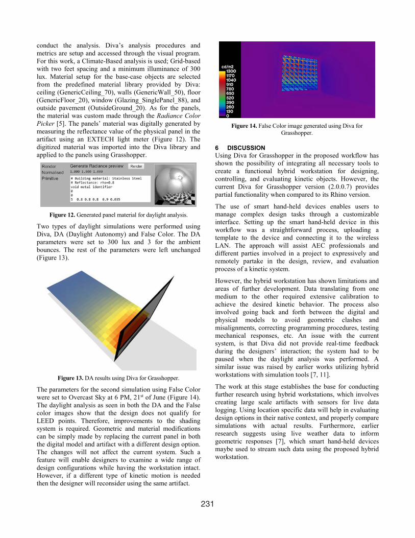
The parameters for the second simulation using False Color were set to Overcast Sky at 6 PM, 21st of June (Figure 14). The daylight analysis as seen in both the DA and the False color images show that the design does not qualify for LEED points. Therefore, improvements to the shading system is required. Geometric and material modifications can be simply made by replacing the current panel in both the digital model and artifact with a different design option. The changes will not affect the current system. Such a feature will enable designers to examine a wide range of design configurations while having the workstation intact. However, if a different type of kinetic motion is needed then the designer will reconsider using the same artifact.
Figure 14. False Color image generated using Diva for
Grasshopper.
6 DISCUSSION Using Diva for Grasshopper in the proposed workflow has shown the possibility of integrating all necessary tools to create a functional hybrid workstation for designing, controlling, and evaluating kinetic objects. However, the current Diva for Grasshopper version (2.0.0.7) provides partial functionality when compared to its Rhino version.
The use of smart hand-held devices enables users to manage complex design tasks through a customizable interface. Setting up the smart hand-held device in this workflow was a straightforward process, uploading a template to the device and connecting it to the wireless LAN. The approach will assist AEC professionals and different parties involved in a project to expressively and remotely partake in the design, review, and evaluation process of a kinetic system.
However, the hybrid workstation has shown limitations and areas of further development. Data translating from one medium to the other required extensive calibration to achieve the desired kinetic behavior. The process also involved going back and forth between the digital and physical models to avoid geometric clashes and misalignments, correcting programming procedures, testing mechanical responses, etc. An issue with the current system, is that Diva did not provide real-time feedback during the designers’ interaction; the system had to be paused when the daylight analysis was performed. A similar issue was raised by earlier works utilizing hybrid workstations with simulation tools [7, 11].
The work at this stage establishes the base for conducting further research using hybrid workstations, which involves creating large scale artifacts with sensors for live data logging. Using location specific data will help in evaluating design options in their native context, and properly compare simulations with actual results. Furthermore, earlier research suggests using live weather data to inform geometric responses [7], which smart hand-held devices maybe used to stream such data using the proposed hybrid workstation.

232
7 CONCLUSION Conventional GUI applications may provide convenient tools to design and evaluate kinetic systems. Nevertheless, hybrid workstations may provide a valuable addition for digital designs workflows with extended interactive and responsive capabilities. Their ability to associate digital and physical geometric and non-geometric information together will assist designers in the progress of their work.
The work presented in this paper demonstrates an approach for creating hybrid workflows to design kinetic elements for daylight applications. The work focuses on the integration of modeling and simulation tools in a single workflow to combine the commonly separated tasks involved in daylighting (physical studies, modeling, simulation, etc.). The integration provides real-time interaction and response through smart hand-held devices. Additionally, the work provides a concise approach to design, setup, test, and evaluate a kinetic design object to address environmental issues.
REFERENCES 1. Al-Qattan, E., Galanter, P., Yan, W. Developing a
tangible user interface for parametric and BIM applications using physical computing systems. Proc. eCAADe 2016.
2. Dourish, P. Where the Interaction is: The foundations of Embodied Interaction. MIT Press, Cambridge, MA, USA, 2001.
3. ElGhazi, Y.S., Mahmoud, A.H.A. Origami explorations: a generative parametric technique for kinetic cellular façade to optimize daylight performance. Proc. eCAADe 2016.
4. Hornecker, E., Buur, J. Getting a grip on tangible interaction: a framework on physical space and social interaction. Proc. ACM CHI 2006.
5. JALOXA Radiance Color Picker. http://www.JALOXA.eu/. As of 22 September 2012.
6. Kensek, K.M., Hansanuwat, R. Environment control systems for sustainable design: a methodology for testing, simulating and comparing kinetic façade systems. Journal of Creative Sustainable Architecture & Built Environment 1(2011), 27-45.
7. Kensek, K.M. Integration of environmental sensors with BIM: case studies using Arduino, Dynamo, and Revit API. Informes de la Construccion 66, 536 (2014), e044.
8. Milgram, P., Kishino, F. A taxonomy of mixed reality visual displays. IEICE Transactions on Information and Systems E77-D, 12 (1994), 1321-1329.
9. O’Sullivan, D., Igoe, T. Physical Computing: Sensing and Controlling the Physical World with Computers. Thomson, Boston, MA, USA, 2004.
10. Payne, A. Johnson, J.k. http://www.fireflyexperiments.com/. As of 2012.
11. Plotnikov, B., Schubert, G., Petzold, F. Tangible Grasshopper: a method to combine physical models with generative parametric tools. Proc. eCAADe 2016.
12. Salim, F.D., Mulder, H.M., Burry, J.R. Form fostering: a novel design approach for interacting with parametric models in the embodied virtuality. Journal of Information Technology in Construction 16 (2011) 133-148.
13. TouchOSC editor. http://www.hexler.net/. As of 2017.