paradise.caltech.edu · 2017-05-17 · calculus is shown to be exactly analogolls tn the calculus...
27
1. Introduclion A Symbolic Analysis of Rclay and Switching Circuit s· Clolldt' E. Shannon" In the control and protecti ve circuits of complex electrical systems it is frequently necessary 10 make intricluc interconnections of re l ay C0ll13C IS and switches. Exampl es of these c ircuits occur in automalic telephone exchanges, industril:ll molor-controi equipment. and in almost any circuits designed to perform complex operations automa ti cally. In this paper Ii mathematical analysis of ccrtuin uf the propt!rties of such networks will be made. Particular anemion will be given to the p rOb lem of network synthesis. Given certain characteristics. it is required 10 find a circuit in corporating these characteristics. The solulion of this type of pmblcm is 1101 uniq ue and methods of findi ng those particular circuits requi ri ng the least number of re lay contacts and switch blades will be studied. Methods will also be described for finding any number of circ ui t.s equivalent to tl given circuit in all operating characteristi cs. It will be shown thaI several of the well-knnwn lhenrcms on impedance networks have roughly analogous th eorems in relay circuits. Notable among these arc thc dclta-w),c and star-mesh transfonnations, and the duality theorem. The method of attack on these problcms may be described brieRy as follows: any circuit is represented by a se t of equations, Ih e te rm s of the equations cO ITe sponding 10 the various relays and switches in the c irc ui t. A calculus is developed for manipulating these equalions by simple mathematical most of which are si mi lar 10 ordinary al gebraic algorisms. This calculus is sho wn to be exactly analogolls tn the c al culus of propositions used in Ihe symbolic study or logic. For the synthesis problem th e desired characteri s ti cs arc first wrillcn Ii system of equations, lind the equations are then manipulated into the form represenling the simplest circuil. lllc: circuit may then be immcdi li tcl y lI mwn rrom the equations. By this method it is always pm:-. ib lc to find the simplest circuit containing o nl y series and parallel cnnneclions, amI in some cases th e simplest circuit containing any type of connection. Ou r notation is taken c hi efly from symbolic logic. or Ihe many systems in common use we have chosen the one which seems simplest and most suggestive for our int erpretation. Some or our phraseology, such as node. mesh. de ll a, wye, elC., is bomlwed frum ordinary network Ihcory for simple concepts in sw it ching circuits. Tra'u(K'limu Am,, /cQlI II/sliw;, of t:ltCfrkal E"gi" .. UJ. ,· uJ. 51. 1 938 . (Paper numhcr . \11· 110, n:cGTTlrr'lendcd by [he AlEE commill cCS on com municlltiun i11Kl bask sciences at the AlEE surr,mcr convcmion. WasllingtOl'l , D.C .. June 20-24. t938 . Miilluscripl Man::h I, 19.38 : made available for prt' : Jri nting Mily 27 . 1938 .) •• CJa\iOo:: E. Shill1nvo I) u re .... arch in the c1efJilnmcm of el cctrical engince"nl ilt of Technology, Camhri c1gc. This paper ii an abStnlCI 01' I p1"CloCme'd ill MIT (or . he or maMer of science. The author indthted 10 Doctor F. L. Hhcheod.:, Uuc1UI VanlK" ' '''- Bu o;h, and Doctor S. H. Caldl"cll. all of M IT , for helpful ellO:uurul","""llililld ni licism. '"
Transcript of paradise.caltech.edu · 2017-05-17 · calculus is shown to be exactly analogolls tn the calculus...
1. Introduclion
A Symbolic Analysis of Rclay and Switching Circuits·
Clolldt' E. Shannon"
In the control and protective c ircuits of complex e lectrica l systems it is frequent ly necessary 10 make intricluc interconnections of relay C0ll13CIS and switches. Examples of these circuits occur in automalic telephone exchanges, industril:ll molor-controi equipment. and in almost any circuits designed to perform complex operations automatically. In thi s paper Ii mathematical analysis of ccrtuin uf the propt!rties of such networks will be made . Particular anemion will be given to the prOblem of network synthesis. Given certain characteristics. it is required 10 find a circuit incorporating these characteristics. The solulion of this type of pmblcm is 1101 unique and methods of findi ng those particular circuits requiring the least number of relay contacts and swi tch blades will be studied. Methods will also be described for finding any number of circui t.s equivalent to tl given c ircuit in all operating characteristics. It will be shown thaI several of the well-knnwn lhenrcms on impedance net works have roughly analogous theorems in relay circuits. Notable among these arc thc dclta-w),c and star-mesh transfonnations, and the dual ity theorem.
The method of attack on these problcms may be described brieRy as follows: any circuit is represented by a set of equations, Ihe terms of the equations cOITesponding 10 the various relays and switches in the c ircui t. A calculus is deve loped for manipulating these equalions by simple mathematical proces~s, most of which are simi lar 10 ordinary al gebraic algorisms. This calculus is shown to be exact ly analogolls tn the calculus of propositions used in Ihe symbolic study or logic. For the synthesis problem the desired characteristics arc first wrillcn a.~ Ii system of equations, lind the equations are then manipulated into the form represenling the s implest circuil. lllc: circuit may then be immcdili tcly lImwn rrom the equations. By this method it is always pm:-. iblc to find the simplest circuit containing only series and parallel cnnneclions, amI in some cases the simplest c ircuit containing any type of connection.
Our notation is taken chiefly from symbolic logic. or Ihe many systems in common use we have chosen the one which seems simplest and most suggestive for our interpretation . Some or our phraseology, such as node. mesh. della, wye, elC., is bomlwed frum ordinary network Ihcory for simple concepts in sw itching circuits.
Tra'u(K'limu Am,,/cQlI II/sliw;, of t:ltCfrkal E"gi" .. UJ. ,·uJ. 51. 1938. (Paper numhcr .\11·110, n:cGTTlrr'lendcd by [he
AlEE commillcCS on communicllt iun i11Kl bask sciences ~"d rre'\t!m~d at the AlEE surr,mcr convcmion. WasllingtOl'l , D.C .. June 20-24. t938. Miilluscripl ~ubmiuec1 Man::h I , 19.38: made available for prt' :Jrinting Mily 27.
1938.) •• CJa\iOo:: E. Shill1nvo I) u re .... arch 3~sj~.ant in the c1efJilnmcm of elcctrical engince"nl ilt MIIS~~hu:;c,U~ 11I~ litute of
Technology, Camhri c1gc. This paper ii an abStnlCI 01' I thc ~i ~ p1"CloCme'd ill MIT (or .he de,.~ or maMer of science. The author i~ indthted 10 Doctor F. L. Hhcheod.:, Uuc1UI VanlK" ' '''- Buo;h, and Doctor S. H. Cald l"cll. all of MIT ,
for he lpful ellO:uurul","""llililld ni licism.
'"

C. E. Shannon
11. Series-Parallel Two_Terminal Circuits
Fund3m~ntal Definitions and Poslulates
We shall limit our treatment o f circuits containing only relay contacts and switches. and therefore lit any g iven lime Ihe circuit between !lily two terminals must be either open (infi ni te impedance) or c losed (zero impedance). Let us associate a symbol X.m o r more simply X. with the tenninals a and b. This variable. a function of lime, will be called the hindrance of the two-terminal circuit a -b. The symbol 0 (zero) will be used In represent Ihe hindrance of a closed circuit . and lAe w mbol I (unity) In represent the hindrance o f an open circuil. T1lus when the circuit a - b is open Xob = I and when closed Xu}, = O. Two hindrances Xab and X cd will be said 10 be equa l if whenever the circuit a - b is open, Ihc c ircuit c - d is open. and whenever a - b is closed. c - d is closcd. Nnw let Ihe symbol + (plu s) be defined to mean the series connection o f the two-terminal cireuits whose hindrances are added together. Thus X /lh + X nJ is tile hindrance of the circuit a - d when I) and c: are connected together. Similarly the product of twO hindrances X"b . X~d o r mure hriefly X"bX cd will be defined to mean tht: hindrance of the circuil furmet..! hy connecting the circuits a - b and c - d in pllrll. llcl . A relay contact or switc h wi ll be represented in a circui t by the symbol in Figure I. the leiter being the corresponding hindrance function . Figure 2 shows the interpretatio n of the plus sign and Figure 3 lhe multiplication sign. This choice of symbols makes the manipulation o f hi ndrdoces very sim ilar tt) ordinary numerical algebra.
X.b iI_ ,;,--b
f i,urot 1 (Iotfl). SymbClI fCl' hlndl'lnu func1iOl"
Ft!fur. 1 (middlot), inierprtt.tiCln Clf ... ultipli. (.Ilion
It is evident that wilh the above definilion.~ the fo llowing postu lates will ho ld :
l. u. 0·0 = 0
b. , + , = , 2. fl. , +0 =0+
b. 0· , = ' ·0 =
3. u. 0 +0=0
b. ,., = ,
, =
0
Postulates
A closed circuit in parallel wilh a c losed circui t is a closed circuil. An open circuit in series with lin open c ircui l is an open circuit . An open circuit in series with a c1oSt.'\J circui l in either order (i.e .. whether the opcn circui t is to Ihe right or left of the closed ci rcuit) is an open circuit. A closed ci rcuit in paralle l with all opcn circuit in e ither order is a closed circuit. A clost:d circuit in series wilh a closed circuit is a closed circuil . An open circuit in parallel wilh an open circu it is an optn circuit.
4 . At any given lime either X = 0 or X = 1.

A Symbolic Analysis o f Relay and Switching Circuits 473
These are sufficient to develop all the theorems which will be used in connection with circuits containing only series and parallel connections. The posrulates are arranged in pairs to emphasize a duality relationship between the operations of addition and multiplication and the quantities zero and one. Thus if in any of the a postulates the zero's are replaced by one's and the mult iplications by additions and vice versa. the corresponding b postulate wi ll result . This fact is of great importance. It gives each theorem a dual theorem. it being necessary 10 prove only one to establish both . The only one of these postulates which di ffers from ordinary algebra is I b. However. this enables great simplifications in the manipulation of these symbols.
Theorems
In th is section a number of theorems governing the combination of hindrances will be given. Inasmuch as any of the theorems may be proved by a very si mple process. the proofs will not be given except for an illustrative example. The method of proof is that of "perfect induction." i.e .. the verifica tion of the theorem for all possible cases. Since by Postulate 4 each variable is limited to the values 0 and I. this is a simple matter. Some of the theorems may be proved more elegantly by recourse to previous theorems. but the method of perfect induction is so universal that it is probably to be preferred.
X+y=y+X. (la)
XY = YX . (I b)
X + ( Y + Z) = (X + Y) + Z . (2a)
X(YZ) = (XY)Z. (2b)
X( Y + Z) = Xy + XZ • (3a)
X + YZ = (X + y)(X + Z) • (3b)
I'X = X. (4a)
O+X=X. (4b)
I + X = I (Sa)
O'X = O. (5b)
For example. to prove Theorem 4a. note that X is ei ther 0 or I. If it is O. the theorem follows from Postu late 2b: if I. it follows from Postu late 3b. Theorem 4b now follows by the duality principle. replacing the I by 0 and the ' by +.
Due to the associative laws (2a and 2b) parentheses may be omitted in a sum or product of several terms without ambigui ty. The Land n symbols will be used as in ordinary algebra.
The distributive law (3a) makes it possible to " multiply out" products and to factor sums. The dual of thi s theorem. (3b). however. is not true in numerical algebra.
We shall now define a new operation to be called negation. The negative of a hindrance X will be written X' and is defined to be a variable which is equal to I when X equals 0 and equal to 0 when X equals I. If X is the hindrance of the make contacts of a relay, then X' is the hindrance of the break contac ts of the same relay. The definition of the negati ve of a hindrance gives the following theorems:
X + X' = I . (6a)

474
xx' = 0 ,
0' = 1 ,
I ' = 0,
(X')' = X .
C. E. Shannon
(6b)
(7a)
(7b)
(8)
Analogue With the Calculus of Propositions
We are now in a position to demonstrate the equivalence of this calculus with certain elementary pans of the calculus of proposit ions. The algebra of logic 1-3, originated by George Boole, is a symbolic method of investigating logical relationships. The symbols of Boolean algebra admit of two logical interpretations. If interpreted in tenns of classes, the variables are not lim ited to the two possible values 0 and I. This interpretation is known as the algebra of classes. If, however, the tenns are taken to represent propositions, we have the calculus of propositions in which variables are limited to the values 0 and I,' as are the hindrance functions above. Usually the two subjects are developed simultaneously from the same set of postulates, except for the addition in the case of the calculus of propositions of a postulate equivalent to Postulate 4 above. E. V. Huntington' gives the following set of postulates for symbolic logic:
1. The class K contains at least two distinct e lements.
2. If 0 and b are in the class K then 0 + b is in the class K.
3. 0 + b = b + o.
4. (0 + b) + c = 0 + (b + c).
5. a + a = a.
6. ob + ob' = 0 where ob is defined as (0' + b')' .
If we let the class K be the class consisting of the two elements 0 and I, then these postulates follow from those given in the fi rst section. Also Postulates I, 2, and 3 given there can be deduced from Huntington's postulates. Adding 4 and restricting our discussion to the calculus of propositions, it is evident that a perfect analogy ex ists between the calculus for switching circuits and this branch of symbolic logic." The two interpretations of the symbols are shown in Table I.
Due to th is analogy any theorem of the calculus of propositions is also a true theorem if interpreted in terms of relay circuits. The remaining theorems in thi s section are taken directly from th.is fi eld.
De Morgan's theorem:
(X + Y + Z ... )' = X '· Y' ·Z' . . . ,
(X·Y ·Z ... )' = X' + y ' + Z' + ...
(9a)
(9b)
This refers only 10 the class ical theory of the calculus of propos itions. Recenlly some work has been done with logical systems in which propositions may have more Ihan [wo " truth values."
This analogy may also be seen from a slighlly differem viewpoint. Inslead of assoc ialing X JIb directly wilh the circuil a - b leI X (fb rtprtSCnl the proposition that the circui t 0 -b is open. Then all the symbols are directly inlerpreted as propos itions and the operations or addition and multiplication will be seen to represent series and parallel connections.

A Symbolic Analysis of Relay and Switching Circuits 475
This theorem gives the negative of a sum or product in terms of the negatives of the summands or factors. It may be easily verified for two terms by substituting all possible values and then extended to any number n of variables by mathematical induction.
A function of certain variables X" X, ..... X n is any expression formed from the variables with the operations of addition, multiplication, and negation. The notation [(X, ,X , , ...... X n) will be used to represent a function . Thus we might have[(X,Y ,Z) = XY + X' (Y' + Z') . In infinitesimal calculus it is shown that any function (providing it is continuous and all derivatives are continuous) may be expanded in a Taylor series. A somewhat similar expansion is possible in the calculus of propositions. To develop the series expansion of functions first
note the following equations:
( lOa)
[CX" .. .,Xn) = [[(O,X , ... X n) + X,] ' [[( I ,X ,,,,Xn) + X,] ( lOb)
These reduce to identities if we let X, equal either 0 or I . In these equations the functi on [ is said to be expanded about X ,. The coefficients of X, and X; in lOa are functions of the ( II - I ) variables X , ... X n and may thus be expanded about any of these variables in the same manner. The addi tive terms in l Ob also may be expanded in this manner. Expanding about X, we have:
[(X, ... X n) = X, X,[( I , I ,X , ... X n) + X, X\[(1 ,O,X , ... X n) +
X;X,[(O,I ,X , ... X,,) + X;X2f(O ,O.X , ... Xn) . (II a)
[ (X, ... X n) = IX , +X, + [(O,O ,X , ... Xn) ]· IX, +X; +[<O,I .X, ... Xn ) ]·
[X; + X, + [(I,O.X, ... Xn)] · [X; + X; + [(I.I.X, ... Xn)] . ( lib)
Continuing this process 11 times we will arrive at the complete series expansion having the form :
[(X, ... X,,) = [C I.I.I ... I )X,X,,, ,Xn + [(0.1, 1 ... I )X;X ,,,,Xn +... ( 120)
+ [(O.O,O ... O)X;X; ... X; •
! (X, .. . Xn) = [X, + X, +"' Xn + !(O.O.O ... O)] · ...
' [X ; + X; .. · + X; + [ ( 1, 1 ... 1) ] .
( 12b)
Table I. Analogue Between the Calculus or Propositions and the S)'mbolic Relay Analysis
Symbol
x o
X+Y
Xy
x'
=
Interpretation in Relay Circuits
The circuit X The circuit is closed The circuit is open The series connection of circuits X and Y
The parallel connection of circuits X and Y
The circuit which is open when X is closed and closed when X is open
The circuits open and close simultaneously
Interpretation in the Calculus of Propositions
The proposition X The proposition is false The proposition is true The proposition which is true if either X or Y
is true
The proposition which is true if both X and Y are true
The contradictory o f propos ition X
Each proposition implies the other

476 C. E. Shannon
By 12a. [ is equal to the sum of the products fonned by pennuting primes on the tenns of X, X 2"'X, in all possible ways and giving each product a coeffi cient equal to the value of the function when that product is I. Similarly for 12b.
As an application of the series expansion it should be noted that if we wish to fi nd a circuit representing any given function we can always expand the function by either IDa or lOb in such a way that any given variable appears at most twice , once as a make contact and once as a break contact. This is shown in Figure 4. Similarly by II any other variable need appear no more than four times (twO make and two break contacts). etc.
Figure.4. Expension .bout onl: n riablc
A generalization of De Morgan's theorem is represented symbolically in the fo llowing equation:
[(X, .X 2 ... X ,. + .·) ' = [(X;.X; ... X;. ·.+) . ( 13)
By this we mean that the negative of any function may be obtained by replacing each variable by its negative and interchanging the + and ' symbols. Ex plici t and implicit parentheses will. of course. remain in the same places. For example. the negative of X + Y'(Z + WX') will be X' [Y ' + Z'(W' + X)] .
Some other theorems useful in simpli fying expressions are given below:
X = X + X = X + X + X = etc .•
X = X'X = X 'X'X = etc .•
X + XY = X .
X(X + Y) + X
XY + X' Z = XY + X' Z + YZ .
(X + Y)(X' + Z) = (X + Y)(X' + Z)(Y + Z)
X[(X .Y.Z . ... ) = X[( I .Y.Z .. .. ) •
X + [(X. Y.Z .... ) = X + [(O .Y.Z . ... )
X ' [(X. Y. Z .. .. ) = X' [(O.Y.Z .... ) .
X' + [(X.Y.Z .. .. ) = X' + [( I .Y. Z, .. . )
All of these theorems may be proved by the method of perfect induction.
(l 4a)
(14b)
(ISo)
(ISb)
( 16a)
( 16b)
( 173)
( 17b)
( 18a)
( 18b)
Any expression fonned with the operations of addition. multiplication. and negation represents explicitly a circuit contain ing on ly series and paraUel connections. Such a circuit will be called a series-parallel ci rcuit. Each leller in an express ion of this sort represents a make or break relay contact. or a switch blade and contact. To fi nd the circuit requiring the least number of contacts. it is therefore necessary to manipulate the expression into the form in which the least number of letters appear. The theorems given above are always sufficient to do

A Symbolic Analysis of Relay and Switching Circuits 477
this. A little practice in the manipulation of these symbols is all that is required. Fonunately most of the theorems are exactly the same as those of numerical algebra - the associative. commutative. and distributive laws of algebra hold here. The wri ter has found Theorems 3. 6. 9. 14. 15. 16a. 17. and 18 to be especially useful in the simplification of complex expressions.
Frequently a function may be written in several ways. each requiring the same minimum number of elements. In such a case the choice of circuit may be made arbitrarily from among these. or from other considerations.
Fi9ure 5. Circuit to be simplified
As an example of the simplification of expressions consider the circuit shown in Figure 5. The hindrance function X oh for this circuit will be:
X ab = W + w' (X + Y) + (X + Z)(S + w' + Z)(Z' + Y + S' V)
= W + X + Y + (X + Z)(S + I + Z)(Z' + Y + S' V)
= W + X + Y + Z(Z' + S'V) .
These reductions were made with 17b using first W. then X and Y as the "X" of 17b. Now multiplying out:
X ab = W + X + Y + ZZ' + ZS'V
=W+ X +Y+ZS'V.
The circuit corresponding to this expression is shown in Figure 6. Note the large reduction in the number of elements.
Fi9ure 6 . Simplification of figure 5
It is convenient in drawing circuits to label a relay with the same letter as the hindrance of make contacts of the relay. Thus if a relay is connected to a source of voltage through a network whose hindrance function is X. the relay and any make contacts on it would be labeled X. Break contacts would be labeled X' . This assumes that the relay operates instantly and that the make contacts close and the break contacts open simultaneously. Cases in which there is a time delay will be treated later.
III. Multi-Terminal and Non-Series-Parallel Circuits
Equivalence of II-Terminal Networks
The usual relay control circuit will take the form of Figure 7. where X , . X, .... X n are relays or other dev ices controlled by the circuit and N is a network of relay contacts and switches. It is desirable to find transformations that may be applied to N which will keep the operation of
478 C. E. Shannon
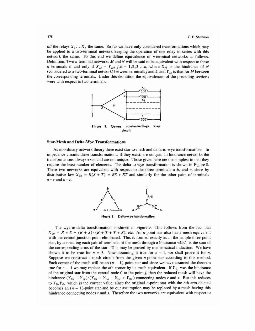
all the relays X I • ... X" the same. So far we have only considered transformations which may be applied to a two-terminal network keeping the operation of one relay in series with this network the same. To this end we define equivalence of ,,-terminal networks as follows. Definition: Two ,,-terminal networks M and N will be said to be equivalent wi th respect to these " terminals if and only if X j • = Yj .; j .k = 1,2,3 .... " . where X j • is the hindrance of N (considered as a two-terminal network) between terminalsj and k, and Yjl is that for M between the corresponding terminals. Under this definition the equivalences of the preceding sections were with respect to two terminals.
x,
zl--....rtIW~--+ Xz
N o
Xn n
Fi9ure 7. Gener.1 conltint·volt.9C rclay circuit
Star-Mesh and Delta-Wye Transformations
As in ord inary network theory there exist star-la-mesh and delta-to-wye transformations. ]0
impedance ci rcuits these transformations, jf they exist, are unique. In hindrance networks the transformations always ex ist and are nOl unique. Those given here are the simplest in that they require the least number of elements. The delta-to-wye transformation is shown in Figure 8. These two networks are equivalent with respect to the three terminals a .h. and c. since by distributive law X ab = R (S + T ) = RS + RT and similarly for the other pairs of terminals a - c and /) - c.
Fi,ure 8. Delt.-wyc translormation
The wye-to-deha transformation is shown in Figure 9. This follows from the fact that X uh = R + S = (R + S) · (R + T + T + S), etc. An II-point star al so has a mesh equivalent with the central junction point eliminated. This is formed exactly as in the si mple three-point star. by connecting each pair of terminals of the mesh through a hindrance which is the sum of the corresponding arms of the star. This may be proved by mathematical induction. We have shown it to be true for " = 3. Now assuming it true for n - I, we shall prove it for n. Suppose we construct a mesh c ircuit from the given n-point star according to this method. Each corner of the mesh will be an ( n - I )-point star and since we have assumed the theorem true for n - I we may replace the nth corner by its mesh equivalent. If Y OJ was the hindrance of the original star from the central node 0 to the point j. then the reduced mesh will have the hindrance ( Yo, + Yo,)·(Yo, + Yo, + Yo, + Yo,) connecting nodes rand s. But this reduces to Y Os Y Or which is the correct value, si nce the original n-point star with the nth ann de le ted becomes an ( n - I )-point star and by our assumption may be replaced by a mesh having this hindrance connect ing nodes rand s. Therefore the two networks are equivalent with respect to

A Symbolic Analysis of Relay and Switching Circuits 479
the first 1/ - I terminals. By eliminating other nodes than the IIIh, or by symmetry, the equivalence with respect to all n terminals is demonstrated.
Figure 9. Wye-delt. transformation
Hindrance Function of a Non-Series-Parallel Network
The methods of Pan II were not sufficient to handle circuits which contained connections other than those of a series-parallel type. The " bridge" of Figure 10. for example. is a nonseries-parallel network. These networks wi ll be treated by first reducing to an equivalent series-parallel ci rcuit. Three methods have been developed for finding the equivalent of a network such as the bridge.
The first is the obvious method of applying the transformations until the network is of the series-parallel type and then wri ting the hindrance function by inspection. This process is exactly the same as is used in simpl ifying the complex impedance networks. To apply thi s 10
the circui t of Figure 10, first we may eliminate the node c. by applying the star-to-mesh transformation to the star a-c. b - c. d -c. This gives the network of Figure 11 . The hindrance function may be written down from inspection for this network:
X u. : (R + S)[U(R + T) + V(T + S)] .
Thi s may be written as
Xu. : RU + SV + RTV + STU: R(U + TV) + S(V + TU)
Figure 11 . Hindrance function by means of transformation.
The second method of analysis is to draw all possible paths through the network between the points under consideration. These paths are drawn along the lines representing the component hindrance elements of the circuit. If anyone of these paths has zero hindrance, the required

"" C. E Shannon
function must be zero. He nce if thc n:sull is wrinen as a product. the hindrance of each path will be a factor o f this pmduci. The required resull may therefore be wrillen 3S Ihe product of the hindnmccs of all possible palhs between the two points. Palhs which louch the same point mOTe Ihan once need not be considered. In Figure 12 this method is applied 10 the bridge. The paths are shown dOlled. The fu nction is therefore given by
X ob = (N + S)(U + V)(R + T + VHU + T + S)
= RU + SV + Rnl + UTS '" R(V + 711) + S(V + TV)
The same result is Ihu.~ ublained as with the fi rst method.
FI!UfI 11. Hlndf.nce Jundion ., • product of .ums
The thi rd method is to draw all poss ible li nes which would hreak the circuil between the pninls under consideration, making the lines go through Ihe hindrances of the circui t. The resull is wrillen as a sum, each Icnn corresponding to 3. cert3.in line. These tc nns arc fhe products of all the hindrances on the line. The justification nf the method is similar 10 that for Ihe second method. This method is upplied to the bridge in Figure 13.
R'\'~/ S
-<{--J '>'f>-• i(1)-'>"1- '. b I , ... , I .. ... , u' , v
FI911re 13 . Hlndf.nc. , .. nction IS • ,urn 01 products
Thi s again gives for the hindrance of the network:
X g " = RU + SV + RT\! + STU = R {U + n'l + S{V + TU)
The third method is usually Ihe most convenient and rapid, for it gives the resul t directly as a sum. It seems much eas ier to handle sums than products due. no doubt. to the fact that in ordinary algebra we huvc the distributive law X{Y + Z) = Xy + XZ, but not its dual X + YZ = (X + Y)(X + Z). II is. howe\'er, somelimes difficull to apply Ihe third method to
nuuplanar networks (ne tworks which cannot be d rawn un it plane without crossing lines) and in this case one of the other twO mclh(xl~ may be used.
SimultaneclUs E(IUafions
In analyzing a given circuit it is cnnvcnient 10 divide the various variables into two classes. Hindrance element.s which are directly comrolled by a ~tlurt:c cK temal 10 the ci rcuit under cnnsiderarion will be called independent variables. These will inc ludt= hand-operated swi tches.

j\ Symbutic Anillysis of lttlllY and Swilching Circu ils '" contacts on ex ternal relays. e tc. Relays and other devices controlled by the network v.'ill be called dependem variables. We shall. in general. use the curlier letters of the alphahcl to represent independent variables ant.I the later IeUe.,; for dependent variables. In Figure 7 the dependent variables are X I'X 2 . .. x ". X t wi ll evidently be operated if and only if Xm = O. where X 0' is the hindrance function of N between terminals 0 and k. That is.
X~=XOk. k = 1.2 . .. n .
TIlis is a .~ystcm (If equations which completely define the operation of the system. The righthand members will be known functions involving Ihe various dCpi;ndcnl and independcnT variables and given the sLuning conditions and the values of the independent vari ables the dependent variahles may be computed .
A transform :uion will now be described for reducing Ihe numhcr of clements required to rcali!.!: a selnf simultaneous equations. Thi s transformat ion keeps X Ol.(k = 1.2 ... 11) invariant. but Xji,(j.k = 1.2 .. . 11) may be changed. so that Ihe new network may not be equivalent in the strict sense detined to Ihe old one. The operation of all the relays wi ll be the same. however, Thi s simpJificHtilln is nnl y applicable if the X Ot fu nctions are wri tten as sums and cenain terms arc common 10 rwo or more equations. For example. suppose the set or eq uation), is as fulluws:
W=A + B +CW .
X=A+IJ+WX
Y=A+CY .
Z=l:.7. + F .
This may be realized with the circuit of Figure 14. using only lIlIC A clemcnt fur thc Ihree places whcre A I ICC Uni and nnly OflC R elemcnl for ils two appearances. The jusrificalion is (I ll ite obvious. This may be indicated symbolically by drawing a venical line after Ihe terms common to the various equations. as shown below.
w = 8 +
x· " + y. Cy
Z = F + EZ
w
, ,
cw WX
::J-F ~_~ ... zO'--4
FI,urc t 4. EUlllplc of rcduc:tlol'l of wllllyl·

'" C. E. Shannull
II follows from the principle of duality that if we had defined multiplication to represent series conncl.:lion, and addition for parallel connection , exactly the same theorems of man ipulation would be obtained. There wefe twO reasons for choosing the definitions give n. First. as has been mentioned. it is casier to manipulate sums than prodUCL'i and the transformation just described can only be applied 10 sums (for constant-current relay circuits Ihis cond ition is exactly reversed). and second. this choice makes the hindrance functions closely analogous to impedances. Under the altemative definitions Ihey would Ix: mure si milar lu admitt.ances, which arc less commonly used.
Sometimes lhe relation XY' :: 0 obtains between IWO relays X and Y. This is true if Y can operate only if X is operated. Thi s frequendy occun; in what is known as a sequential system. In a c ircuit of this type (he relays can only operate in a certain order or sequence, the operation of one relay in general "preparing" the circuit so that the next in order can operate. If X precedes Y in the sequence and txlth arc constrained to rema in opcrdted until the sequence is finished then this condition will be fulfilled . . In such a case the following equations ho ld and may sometimes be used for simplificat ion of expressions. If XY' = O. then
x' y ' = y'
XY = X.
x' + Y = I .
X' + y' = X'
X+Y=Y .
These may be proved by adding XY ' = 0 to the left-hand member or mU ltiplying it by X' + Y = I. thus not changing the value. For example. to prove the first one. add XY' to X' Y' and faclOr .
Special Types of Relays and Switches
In certain types of c in.:uils il is nel.:essary 10 pn:M:rvc a definitc scquential relat ion in the operation of the contacts of a re lay. Thi s is done with make-before-break. (or continuity) and break.-mak.e (or transfer) contacts. In handling thi s type of circuit the simplest method seems to be to assume in setting up the equations that the make and break contacL~ opcmle simultaneously, and after all simplifications of the equation s have bee n made and the reSUlting circuit drawn. the required type of contact sequence is found from inspection.
Relays l\a li in!!- a time delay in npcmting or denpcrating may he treated similarl y or hy shifting the time axi s. Thu s if a relay coil is connected to a battery through a hindrance X. and the relay has a delay of p seconds in operating and releasing, then the hindrance function of the contal:ts of the rday will also he X. hut m a time p seconds later. This may be indi cated by writing XU) for the hindrance in series with the relay. and XU - p ) fo r that of the relay contacts .
There are many special types of relays and switc hes for panicular purposes. such as the stepping switches and se lector switches of various sorts. multi winding relays. cross-bar sw itches, etc. The operation of all these Iypes may be described with the words "or." "and," " if, " " operated ," and "not operated." This is a sufficient condition thai [hey may be described in teons of hindrance fu nctions with the operations of addition. multiplication. ne!!-lition, and equality. Thus II two.winding relay might lx: so constructed that it is operated if the first or the second winding is operated (activated) and the first alld the second windings are not operated. If the first winding is X and the second Y. the hindrance function of make

A Symholic Analysis or R.duy lind Swiu:hing C ircuits
contacts on the relay will then he XY +X'Y' . Usually, however, these special relays occur onl y at the end of a complex circuit and may be omitted entire ly from the calculations 10 be added after the rest of th.: circuil is designed.
Sometimes a relay X is to opcnHc when a cireuil R do~s and to remain d osed independenr of R until a ci rcuil S opens. Such a circuit is known as a lock-in circuil. Its equalion is:
X = RX + S .
R.:placing X by X' gives:
x' = RX' + S
'" X"" (R ' +X)S' .
In this case X is tlfH!lIl'd when R closes and remains open until S opens.
IV. Synthesis of Networks
Some (;cnl:!ral Theorems on Networks and Functions
II has been showll that allY function may be expanded in a ~ries consisting uf a .'ium of products. each pnKlucl being of the form X I X l"'X " with some permulalion of primes on the leHers. and each product having the coeffi cient 0 or I. Now since each of the /I variables may or may not have a prime. Iherc is a lOla I of r differe nt products of this fonn. Similarly each product may have the coefficient 0 or the coeffici cnt I so there are 21
'1 possi bl.: sums of th is
sort. Henee we have the theorem: The number of fu nClions obtainabl.: from fI variablt..-s i.'i 2 ~". Each of these sUlm will represcnl a different function. but some of the fum:lions may
at: tually involve fewer than II variables (that is. thcy un: IIf .'im:h a form Ihat for one or more of the /I variables, say XA• we have identically f!x ,.o '" f!x.~ t so Ihm under no conditions doc:. the value of the function depe nd un the value Xl)' Thus for twO variables. X and y, amnng the 16 functions obtuim:d will be X .Y .X ' .r· .D. and I ..... hich do not involve both X and Y. To find the number of functions which actually involve all of the n variables we proc~d as follo ..... s. Let $(11 ) be the number. Then by tht: theorem just given:
22" "" i ['~l $(,{:) . l ., 1\ ,(:
where [1] = 1I! 1,{:! ( 11 - k )! is the number of combinations of II things taken ,(: lIIlJ\imr:. That
is. the to!D.1 number of func:tinns obtai nable from 11 variables is eq ual to the sum of the numbers of those functions obtainable from .:ach possible selection IIf varia bles from th.:se 1/ ..... hich actually involve all th.: variables in the l<iClcct ion. Solving for Q( n) giv.:s
0-' [ 1 ¢( n) = 2" - r ~ W) . ,·· u
By SuhslitUli ng fo r $(11 - I ) on the right the si milar expression found by replacing 1/ by II -in (his equation. then similarly sub:.tiluting for .C" - 2) in the expression thus obtained. ctc., an eq uation ma), Ix: ubt:lined involving only Q(II). 111is equation mit)' then be simplified 10 the fnnn
¢l(II ) = i [~122'( - I ) ~-k . ,.0

4114 C. r,.. Shannon
As " increases this ex pression appro;\cnes its I~ad ing leml 22" asymptOliclilly. The error in using only this term for II = 5 is l e~~ than 0.01 percent.
We shall nuw dctermine those functions of 1/ variables which require the mosl relay contacts 10 realize. and find the number of contacls required. Tn order to do this. it is necessary 10 define a function of two variables known a,~ the sum modu lo twO or disjunct of the variabk s. This funct ion is wriuen X I EB X 2 and is defined by the equation:
Xl EBX 2 = X IX; +X1X1 .
II is easy to show that the sum 1l1ooulu two obeys the commutalive. associative. and the distributive law wi th respecl to mu lti plication. that is.
Alsu
X I EBX 1 = X2 ED X I '
(Xl ffiX z) $ X J = X jEB( X.!.EBX l )
X,(X2EBXl ) = XtXz (J) X,X ) .
(X!EBX ~) ' =XjEBX; = Xi $X~,
X1EDO = X I
XIWI = Xi
Since the sum modulo two obeys the assuchlti vc law, we may omi t parentheses in a sum of several tenns wilhuut Hmhiguity. The sum modulo tWO of the 1/ variables X 1 .x 2 . .. X /I will fur convenience be written:
" X1 EBX 2EBX J ". EBX n = -= Xk ,. , Theorem:' The two functions of /I vari:Jbles which require the most elements (relay
" " L·()l1!lictS) in a series-parallel realization are =.X t and (=.X t)· . each of which requi res , , (3·r - 1 ~ 2 ) e1cmcnt.s.
This will be proved by Ilmthcmaticu l inductiun. First note that it is true for 1/ = 2. There are ten functions involving t ..... o variables. namely.XY. X + y . X ' Y. X· + y . XY', X + y'. X· y'. X' + y'. XY' + X· Y. Xy + X· y' . All of these but the la..,; l lwo requi te two elements: the last tWO requi~ four elements and are X$Y and (Xe y) '. respecti vely. Thus the theorem is true for 1/ = 2. Now u.ssuming it true (or" - I , we shall prov~ it true for 1/ and th us complete the induction. Any funct ion of" variables may be expanded about the nIh vlI.riHble as follows:
!(X 1.X 1". X n ) =! = X ~ !(X1 ·, · X n_ I . I ) +X;r!(X, ... Xn _I.O ). (1 9)
No ..... the terms !eX I ... X II - I ' I ) and /(X I ." X n-I .0) are fu nctions of " - I variables anli if they individua lly require the most e lements for 1/ - I variables. thcn / will require the most elements for " variables. providing therc is nil o thcr me thod of writing /so that fewer elements are required. We havc a.~sumcd Ihal the most element s for " - I variables are re4uired by n- I n-I
=: X ~ and its negat ive. If we, thererure. substitute for I(X 1"'X n- I . 1) the function =. X j . and , , "- ,
ror I(X I" ' X 11 _1 .0) the fu nction ( =. X ~)' we find , • See ' he NOles '0 litiS ~pcr.

A Symbnlic Analysis of Relay lind Switching Cirroils
,, - I ,, _ I "
/ = X .. ~ X ~ + X~( ~ Xd' = ( ~Xt>' , , I
From the symmetry of thi s function there is no other way of expanding which will reduce the nllmber of e lements. If the fUnCtions lire substilUted in the o thc r order we get
,, - I .. -I"
/ :::X,,( ~Xd' + X ~ ~X,. =::Xt . , "
TIlis complclcs the proof that these functions require the most elements.
To show Ihal each requires (J ·r- I - 2) elemenls. lei thc number of elements required be denoled by ,\'( 11 ). Then from (19) we gel the diffcrence equation
s{ n) = 2s( 1/ - I ) + 2 .
with 5(2) ::: 4. This is linear, with constant coeffic i enL~. and may be solved by Ihe usual methods. TIle sol ution is
.f( lI ) = ] ·r- I - 2.
as may easily be verified hy subslitUling in the differellce equation and boundary condilion.
Note Ihal lhe above only applidi lfI a series-parallel realization. In a I;tlcr secTion it will be
" shown that the runction :;X, and its negali ve mlly be real ized with 4( 11 - I ) elements using a , mo~ general type or cireui!. The function requi ring Ihe mOSI e lements using any type of ci rcuit has nOI as yet been dClennined.
Dual Networks
nle neglltive of any network may be found by De Morgan 's Iheorem. bul the network must fi rs l be transfonned into 311 el.juiva1cnl series-paralle l circuit (ulI1css it ;s already of thi s Iype). A theorem willlx:: t1e\leloped with which the negati ve of any phmar rwo-tenninal circuit may he found dil1:l.:tly. As a corollary a melhod of finding a constanl-current circuit equiva lent to a given constant-voltage circuit and \l ice versa will be given.
Let N represent a planar network of hindrances, wilh The function X U/I between the lenninals (J and b which are on the Outer edge IIr the network.. For defi nileness cnnsider rhe network of Figufl: 15 (here the hintlnmccs are shown meu:ly as lines).
Nnw lei M represent the dual of N It.'i found by Ihe following proccss; fur each COntour or mes h of N assign a node or junct iun point of M . For each elemcnt or N. say X k. separating the contours r and .f there cOlTesponds an element X.i. connecting the nodes r and s of M, The area exterior to N is 10 be considered as two meshes. (' and d. corresponding 10 mMJes c and d of M. Thus the dual of Figure 15 is the nelwork of Rgure 16.
~~,
<SJ>s T
a U v b
w ,
"~d
Figure 15 (left). Plu.r n. lworlc lor IIhntrl_ lion of dullty theolll ll'l
,
d
Fi,urll: 16 Crlght). Ou.! 01 figure 15

... C. E. Sh~nnon
Theorem: If M and N bear Ihis duality relationship. then X uh :: X: d • To prove this. lei the network M be superimposed upon N.lhe nodc~ of M within the corresponding meshes of Nand corresponding elemenfS crossing. For the network of Figure 15. lhis is shown in Figure 17 with N solid and M dotted. Incidentally. the easiest method of finding the dual of a network. (whether of this type or an impedance netwurk) is 10 draw the required network superimposed on the given network. Now, if X"b = O. then there must be some path from a to b along the Jines of N such thai every element on this path equals zero. But this path rcprcscnl~ a palh across M dividing the circuit fmm {' In d along which ever)' element of M is one. '·Jenee X rd = I. Simi larly. if X cd = 0, then X a" = I. and it follows that X "I> = X:.J .
, '
• ,
Fig"." 17. Sup"'polition of. nlll1wo'" ud ib dual
~~T .-<R ~ Y>-b '''-.L-. Z
w
Flg"r. 18. Nonpr.n.. nd .... orl!
It is e vident frolll th is Lheorem LhaL a negaLive for any planar network may be realized with the same number of elements as the given network .
t
In a constant-vollage relay system all the rdays arc in parallel across the line. To open a n.:lay a series connection is opened. The general constant-voltage system is shown in Figure 19. In a constant-current system the relays are all ill series in the lim: . To dc-operate a relay it is short-circuited. The general constant-curren! ci rcui t corresponding to Figure 19 is shown in Figure 20. If the relay Y! of Figure 20 is to be operated whenever the relay X! of Figure 19 is operated and not otherwise, thell evidently the hindrance in panl11el with Y J: which short-cin;uits it must be the negative of the hindrance in series with X t which connects it across the voltage source. If this is true for all the relays. we shall say that the constant·current and constant· voltage systems are equivalent. The above theorem may be used to find equivalent circuits of Lhi.~ ~ort, for if we make the networks Nand M of Figures 19 and 20 duals in the sense described, with X A and Y, as corresponding elements, then the condition will be satisfied. A si mple example of this is shown in Figures 2 1 and 22.
E-~~ x, ,
N
Figu." 19 (left). G.n.r.r condlnt-volug. r.l.y circuit
Yo '---_--=:::l
Figur. 110 (right). G.n"r.1 cond.nt·cunent r.rlY circuit
This is nOl in general true if the word "planar·' is omitted. The nonplanar netwnrk X .. ' of Fi,!:ure ill . for Hample.
has no negative cootain ing only eighT etem~r~.

A Symbolic Ana!ysis of Relay and Swilching Circuits
[t,': -[O...L X3
FI,,,,,. iT (tclt). Simpl. conn.nt .. olt.,. lYlbtlll
Synthesis of the General Symmetric Function
II hils been shown that any function represents explicitly a series-parallel circuit. The series-parallel realization may require more elements. however. than some other network representing the sallle funclion. In (his seclion a mctluKl will be given for linding a circuil represent ing a cenain Iype of function which in general is much more economical uf c1emenls Ihan the beSI series-parallel circuit. This type of funClion is known as u symmelric func lion and appears frequentl y in relay ci rcuils.
Definitiol/: A function of the If varillbh::,~ X 1.X 2"' X ~ is said to be symmclric in Ihese variables if any interchange of lhe variables leaves the function identically Ihe same. Thus XY + XZ + YZ i .~ symmetric in the variables X, y, and Z. Since any pennuto.tion of variables may be obtained by successive inten.:lulTIses of two variables. a necessary Ilnd sufficient condition Ihat a fUll cliun he symmetric is that any interchange nf IWO variables kaves the function unaltered.
By proper selection of the variables many apparent ly unsymmetric funr.:tions may be made symmetric. For example. XY'Z + X' yz + X' y' Z' although nol symmetric in X. Y. and Z is symmetric in X . Y. and Z·. II is al so sonlCtimes possible 10 write an unsymmetric fu nclinn as a symmetric function multiplied by a simple tenn or added to a simple tenn . In such a case the symmetric pun may be realized with the methods to be described. and the additional tenn supplied as a series or parallel connection.
The following thcllrcrn forms the basis of the method of design which has been developed.
Tht'or('m: A necessary and suffi cient cundilion thai ;l function be sym metric is that it may be specified by stating a SCI IIf numbers a I. a l ... aA such that if e)('3clly tJ I ( j = 1.2,) ...• ) of the variables arc 7.cro. Ihen the func tion is zero and 1I0t otherwise. This follows easily froll1 the definition. The set of numbers 0 1' tJ ~ ••• lJt may he any sel of numbers selected from the numbers 0 to n inclusive. where n is the number of variables in the symmelric function. For convenience. Ihey will be called the a-numbers of the funclion. The symmetric function XY + XZ + yz Im.~ the tJ-numbers Z and 3. since the function is zero if jusl two of the variables arc zero or if three are zero. but not if none or if onc is 7.ero. To find the a -numbers of a given symmetric function it is merely necessary 10 evaluate the function with 0. 1 ... n of the variables l.cro. TllOse numhcrs for which the result is 'l.ero are the a-numbers nf the function .
Theol"(!m : There are r .. 1 symmetric fune lions of n variables. Thi s follows from Lhe fac t that there are rt + I numbers. eacb of which may be taken or not in our selectiun uf a-numbers. Two of Ihe functions are trivial. however. namely. those in which all and one of Ihe numbers are taken. These give the ·· (unctions" 0 and I. respecti ve ly. The symmetric function or the n variables X I .X 2 ... X ~ with Ihe a -numbers 0 1 .0 2 .•. tJJ- will be wrillen S .. ," , ..... , (X 1 , X 2. ' •. • X ~). Thus Ihe example given would Ix.: S! J (X. Y.Z). The circuit which has

... C. E. Shannon
been developed for realizing the general symmetric funClion is based on the a-numbcn; of the function and we shall now a ...... umc _hal they are known.
Thf!urt!m: lbc sum (If two given symmetric fu nclion!( of the same set of variables is: II
symmetric function of these variables hav ing for a-numbers those numbers commOn to Ihe IWO given functions. Thus S 1.1.3 (X I ... X 6) +5 2.l.5 (X , ... XI,) = S2.l(X , ... X IS}.
Theorem: 10e product of two given symmctric functions of Ihe same set of variables I!'> a symmetric (unclion of these variables wi lh a ll the numbers appearing in either or bolh of Ihe given t'unclions for lJ-nunihcn;. Thus S 1.1.31.X I •.. X II ) 'S u.s tX I . .. X 6) = s 1.2.3.5(X I ... X 1»'
To pmve Ihese theorems. nOle that a product is zero if either factor is zero. while II su m is 7.c ro only if bolh lerms ilr~ zero.
The()rt'm: The negmive of a symmetric function of n variables is a symmetric fU l1clioll uf these variables having fot a-numbers aJlthc numbers from U 10 /I inclusive whkh arc nOf in fhe a -numbers of the given fune/ion . Thus S2 .3.S (X I .. . X /I) = SO.I.4.6(X / ... X 6 )'
Before considering the synthesis of the gener:lI symmetric function Sa,a,. a. eX I ' X 2 . .... X n ) a simple example wiJl be given. Suppose the (ullction S 2 (X I .X 1.X 3) is to be realized. Th is means ,hal we must construct Ii circuit wtlkh wi ll be closed when any two of the variables X I .X ~ .X J are zero, hUl open if none, or one or Ihree are zero. A circuit for Ihis purpuse is shown in Figure 23. This circuit may be divided into Ihree bays. nne for cach variable. and four levels marked 0, 1.2 ilnd 3 Htthe righl. The terminal b is connected to the \e'lje\s CQne'i"pollO\Il~ \ 0 \\y.: Q-\yumOCl"io. \){ \h\! ltA\\\\t«\ {\\,nc,\;,OO, ;,t\ .. h;'", c ?se \~ \\\~ k'l~\ \'i\'AT\;,ed
2. The li ne coming in at a firsf encounters a pair of hindrances X I and Xi. If X J = 0, the line is sWi fched up 10 the leve l marked 1. meaning lhat one of the va ri llblcs is zero; if not it stays al the same level. Next we come to hindrances X 2 and X ;. If X l = 0, the line is switched up a level ; if nnt. it stays allhe same level. X.l has a similar effect. Finall y reaching the right-hand sel of terminals. the line l'1as been switched up 10 Ii level equHllo fhe lotal number of variables which are zero. Since lI:rminal h is connected 10 fhe leve l marked 2. Ihe circuil a - b wilJ be cumplcfcd if and only if 2 of the variables are zero. If So.) (X I' X 2, X) had been desired. terminal b would be connected to both It:vels 0 and 3. In Figure 23 cenain of the elements lire evidently superfluous. TIle circui t may be simpli fied 10 the fonn of Figure 24 .
•
Fur the general function eXQclly the same melhud is fo llowed . Using the general c ircuit for " variables of Figure 25. the termi nal b is connected 10 the levels correspondi ng to the a·

A Symbolic Anal~ i ~ of Re.lay and Switching Circuir~
//~~n.o
.~-----~: XI x l x,) •••••• ')(n
Fi!Jurc 25. Circuit for rulizin!J lI.c ,cncr.l Iy ....... ctric fune.iion S.,G1 . • . _,(X" XJ , •••• X. )
'"
numben of the desired symmetric fu nction . In Figure 25 the hindrances are respected rnerely by lines, and Ihe letters are omitted from the circuit. but the hindrance of each line may easi ly be seen by generalizing Figure 23. After teml inal h is connected. all superfl uous clements may be deleted.
• ~~Lb XIXZ>\;J x...~X6
FI,lIrt 26. CirCllit for So .•. ' (XI ' .. XI) IIling the ",hifting down" plOCt ..
In certai n cases it is JXlssible to greatl y si mplify [he circuit by shifting the levels down. Suppose the fu nction SO.3.6(X I . . . x 6) is desired. Instcad of continu ing the circuit up 10 the sixth level. we cunnect rhe second leve l back down to the zero level as shown in Fi gure 26. TIle zero Icve llhen also becomes the third level and the sixth leve l. With terminal b connected 10 Ihis leve l. we have reali zed Ihe function with a greal savings of elements. Eli minating unnecessary elements Ihe circ uit of Figure 27 is ubtained. This device is especially useful if Ihe tI-numocr.. form an arithmetic progression. flh hough il can sometimes be applied in other cases .
. ~m~~~~"--b XI X2 XJ x." X.!I }(6
Fl,ute 27. SimplifiCition of A,ure 26
• • The fu nctions =:..x j . and ( :::X t)' which were shown 10 require the mOSI elements for fl series , ,
para lle l realization have very simple circuits when developed in Ihis manner. It can be easily •
shuwn that if II is even. then ~I. is the symmetric fu nction with alilhe even numbers for a, •
numbers. if II is odd il has all the odd numbers for a-numbers. The fu nction ( :::X d' is. of , course. j ust the opposite. Using the shi ft ing-down process the circuits are as shown in Figures 28 ilnd 29. 111ese c i rc ui L~ each require 4( 11 -I ) elements. They will be recogniLcd Ii.."
the fa mil iar circui l for controlling a light from tr points. using (II - 2) duuhle-pole double-throw switches and fWO single-pole double-throw switches. If at anyone of thc points the position of the switch is changed, the tulal number of variables wh ich equal zero is changed by ont!, so lhal if the ligh t is on. il will be turned off and if already off. it will be tumt:uun.

49. C. E. Shaflnorl
Fi!lu", t8. for"
More than one symmenic function of n certain set o f variables may be realized with just ont! circuit of the fom\ of Figure: 2S. pmviding the diffe~nt functions have no a-numocrs in common. If tlll':rc ure common a-numbers the levels may be shifted down. or an extra relay may be added so that one circuit is still sufficient.
The general network of Figure 25 contains n(n + I ) elements. We will show Ih:ll for any given selectio n of a-numbers, at least n of the elements will be superfluous. Each number from I to n - 1 inclusive which is nOl in the set of a-numbers produces two unnecessnry elements; 0 or /I missing will produce olle unnecessary e lement. However, if two o f the a-numbers differ by only one. then two clements wi ll be sup!rfluous. If more than two of Ihe a-numbers are adjal.."Cnt. or if tWO o r mo~ adjacent numbcOl are mi$sing. the n more than one e lement apiece wi ll be supt=rfluous. It is ev ident thcn thai the worst c~ will be that in which the a-numbers are all the odd numocr.; nr all Ihe even numbers from 0 to n. In eRch nf these cases it is easily ~"Cn that II of the e.lemems will be 'Supcrftuous. 1" \he~ cases the shifting down process may be used if II ,. 2 so that the maximum of ,, 2 clements will be needed only for the fnur p:micular functions X. X'. XEElY, lind (XEDYJ'.
• • FI,.,. 29. (EXt ) 101 " eYU, , odd
Equations ,,' rOIll Given Operating Characteristics
b
• (EX.)' 'Of" ,
In general. there is a cenain set of indepe ndent variables A. B. C ... which may be switl:hcs. extemally operated or prot(:1: ti ve relays. There is also a set of dependent vll rillbles x. y. = ... which represent relays. mOlars or o lher devices to be contrOlled by the circuit . It is required 10 find a network. which gives, for each possible combination of values o f the independent variables. the correct values for all the dependent variables. The following principles give the Beneralll lClhutl of $olulion.
I. Additional dependent variables must he introduced for each added phase of operation IIf a sequential system. Thu.~ if it is desired to construCI a system which opcrulcs in three sleps, tWO additional vari ables must be intToduced 10 represcnt the hcginning of Ihe last two steps. These additional variables may represent contacts on a stepping sw itch (If relays whid\ loc k in sequent ially. Similarly each rC4uircd lime de lay will require a new variab le, represcnting a time dctay rcluy of some son . Other fonns of relays which may he necessary will usually be obvious from the nature o f the problem.
2. 1bc hindrolnce equations for each of the dept=ndenl variables should now be .... ·riuen down. These functions may involve any o f the vli riablcs. dependent or independenl. incl uding the variable who$C function is being delennined (as. fo r example. in 11 lock-in circuil). The

A Symbolic Anal~!O of Relay ilnu Switching Circuits
Tllhle II. R~lation or Operilling Cha racteristics and Equations
Symbol
x
x'
+ (- - )'
XU - 1' )
In Terms orOper:llion
1lle switch or reillY X is operated If lllc switch or relay X is not operated 0, Aod The cin:uit t - -) is nnt dosed. or apply
De Morgan' s thl.."Orcm X has been operated ror at least p ~eeonus
In Terms of Nonopc:rulion
111t: switch or relay X is not operated If The ~wjtch or relay X I:. operated Aod 0, The circuit (- - ) is d osed. or apply
De MOfjlll.n·s theorem X ha~ heen open for al kll.sl p seconds
If the dependent variahle appears in its own defining funClion (as in a lock·in circuil) strict ;ldherence to the above leuds to eonfu~ing ~entences . In such cllses the following equivalents should be used. X = RX + S X is operated when R i ~ ctMed
(I"lrO\'iding 5 is closed) and remains so independent of R uotil 5 OlJ(ns
X = (R' + X)S' X is upened ..... hen R. IS dosed (pro\'iding S is c1~, and remains so independent of R unti l S 0lX"n~
In using this rable it is usually bc:sl to wrile Ihc function under considctUliun either a~ iI sum of pure produ~·ts or as 11 product of pUfe sums. In the case of a sum nf products the charucLeristics should be defined in tenllS o( nonuper,!.Iion; for a producr or sums in tenns of operat ion. If this is not donc it i ~
difficutl 10 give implicit and explicit parentheses Ihc proper significance.
conditions may be e ither condilions fUf operation o r for nonoperation. &,ulllions arc wrinen (rom o~raling charaClerislics according to Table II. To iIIuSlnltc the use of Ihis table suppose a relay U is to ujlcnue if.r is operated and )' or : is uperaled and ,' or w o r : is not operated, The c~press ion for A will be
U=,\· +Y:+ I·' W';'
Lock-in re illy equations have already been dhl:usscd . It does not. or course. rtllltter if Ihe same conditions are pUI in the exprl:ssilln more Ihan once. - all supernunus materia l will disappear in the tinal simplification .
. l The ex pressions for the various dependeOl variables should IIc~t he simplified as much as possible by means IIf the Iheorems on manipulation of these quantities. JUSt how much this can be do ne depends somewhat on the ingenuity nf the designer,
4 . The resuiting circuit should now be drawn. Any necessary additions diCiated by practiclil considerat ions such 3S current-carrying ahility. sequence of c.ontact operation. e tc., should be made.
V. lIIus(ra(jn~ F.);amples
In thi s ~Clion severnl pmhlems wi ll be solved with the methods which have been developed. The examples are intended mOre 10 illustmtc the use of the calculus in actual pmhlcms and 1('1 show the versatility o ( re lay and switching circuits than 10 de~cribc practical devices.

C. E.. Shannon
It is possible to perform complex mathematical operations by means of relay c ircuits. Numbers may be represemed by the pusitions of re lays o r stepping switches. and interconnections between sets of relays can be made to represent various mathematical ope rations. In fact. any operation Ih:1t can be completely described in 11 fi nite number of steps using the words. "if." "or," "and," Cle. (M'.e Table 11). can be dom: aUlomatically with relays, The last example is an illustration of a m:nhematical operalion accomplished with re llty)..
A Selecth'f Circuit
A relay U is 10 operate when any (lne. any three or when a ll four of [he relays w. x. y and: arc operaled but not when none or two are opcrulcd. The hindrance func tion fo r U will evidently be:
Reducing to the si mplest series-parallel fo rm :
U;:::; 1I'[.r(y: + y'::') + .r'(y': + Y:') l + 11"[.1'(/: + y:') + x'y: ) .
FI,ure ']0. S .. rlH-JNr.llel re.lil.tlon of 1 .. 1.c:tive circuit
This circui t is shown in Figure 30. II requires 20 clements. However. using lhe symmeuicfunction method. we mu y write for U:
U = SU.4(1I' •• \.y.z)
/--/ r-rr • --L. ..L. ..L. ,../
w x Y l U
Fi,u.a 31. St:lectiva circuit f,o," ,y,"," .. trl.:f., .. ction mC"thocl
Th is circuil (Figure 3 1) contains only 15 elements. A still fun her reduction may be made with the fo llowi ng de vice . Firs t wri te
r~;'l . . ~.....t~_~
w 'I( y l.
FI,ure 32. Hal.live of ..,Iactin circuit fro," ,y",IIIetric-fu .. clion method

J\ Symoolic Anlllysis of Relay and Switching CircU; I~ 49J
TIlis ha.~ thc circuit of Figure 32. What is required is the negative uf Ihi.~ function. This is a planar network and we may apply the theorem un thc dua l of a network, thus obtaining the circuit shown ill Figure 33. Thi s contains 14 elements and is probably the most economical circuil uf any son,
Design ur 1111 F.1t~dric Cumbi nation Lock
An elecuic lock is to be constructed with the fo llowing. chU.r.l.ctcristics. There are to be five pushbutton switches available on the front of the lock. Ihese will be labeled a, b, (" . d, e. To operate the lock the bunons must be pressed in the following order: c, h, a and (" simultaneously, d. When operated in this sequence the lock is tn unlock, but if any bunon is pressed incorrec tly an alaml U is to operate. To relock the system a switch ~ must be operated. To release Ihe alann once it has stalled a switch II must be operated. nti s hcing a sequential system either a stepping switch or additinnHI sl.'q ucnt ilil relays are required . Using sequential n: lays lei them he den01ed by W,.\" , )' and: corresponding respectively to the correct sequence of operating th~ push buttons. An additional time-delay relay is also required due 10 the third slep in Ihe operation. Ohv iou.~ l y, even in correct operat ion a and (cannOI be pr~ssed at ~xact ly
the ..mme time, bUi if only one is pressed and h~ld down the alann should operole. Therefore assum~ an auxiliary lime delay relay I' which will operate if t:ithcr a or (' alone is pressed al the end of step 2 and held down longer than lime $, the de lay of the relay.
"
"_-+====:::~ -------, u y _0 ---=;Tc=.:;~;-:=:;=t-~-l : :r- \1 "0 ___ ' ,
'-___ x, C~., •
W o C , y
; :r: ::~t-~-ml'1f'--l u' _ _ _ o 9'-L II ~ :: _J----------'1~'1f'--~
Z "NO z' ...... lIf !lEFOR!!: 8Rf.AK U ANti U' Ul\J\f BUtlll.t alii!"'!

, .. C. E. Shannon
When z has operated the lock unlocks and IIllhis poimlel all the other re lays drop out of the circuit. TIle cyull liuns (I f the system may be wriuen down immediate ly:
1\' ::: CW + Z' + U ' ,
x = hx + w + :' + U·
y ::: (0 + e)y + x + : ' + U'
.: = :(d + y) + g' + U' •
\' ::: X + oc + o· c' + z· + U·
U = dw ' + uhd)(w + x' + ndJ( x + y' + dl'(r - s) lI y + bv( t - s») U + II' + :' .
The~ expressions Can tx: simpli fied considerably. fi rst by combining the scculld and third factors in the fi rst tenn of U. and then by factoring out the comrnun Icnns of the several functions. The fi nal simplifi ed fo nn is as below: This cOm!sponds to the circuit of Figure 34.
u=
w =
x = Z' +
)' = u' +
"
:. = g' + (y + d): + U '
EI~c1ric: Add er to the Base Two
I! ' + d (ld(b + w ' ) + x' l
(x + y' + dl')(Y + \'b)U
'w
hx + w
(0 + l')y
x +
(1(' + o 'c'
A circuit is to be designed Ihat will automatically IIdd t ..... o num bers. using on ly relays and switches. Althuugh IIny numbering base could be used the c iocuit is greatly simplified by using the scale of two. Each digi l is thus either 0 or I : the number whose digi ts in nrder arc , {jk·at _l, ot _ ~ . · · · 02 .o l.o o hasthevalue L 0) 21. /.,
Le t the two num bers which are CO be added be represented by a series of switches: O' .O' _I .... O I.OU representing the various digi ts of one (If Ihe numbers and b( .. b t _ I ... . h I . h o the tligits of the o the r number. The sum will be represented by the positions of a set of relays Sk+ I,S.,S(_ I ", SI'SO' A number which is carried 10 thejth column from the (j - 1 )th column will be represented by II o:lay cJ' If the va lue of any d ig it is 7.t:rn. the corresponding re lay o r swi tch wi ll be taken to be in Ihe posilion of z.ero hindrance: if one. in the posil ion where Ihe hindrance is one. The actual addition is show n be low:

A Symh<llic Analysb of Relay and Swilchin& Cifl-Uil~
("hi Ct· ("1 +1(", C2el
0t ~-a ,+ I U r·--(12t1 1 (10
h t hJ+l hJ b 2b l b o
Carried numbers FirSI number Second number
Ct+ 1 Sk···Sj.ll·, ···.~: .SISO Sum
0'
.fh l
'"
Staning from Ihe righl . So is one if a n is o lle and ho is zero or if 0 0 is zero IIfld b o one but nOI otherwise. Hence
C I is one i f both tlo and bo are one but not otherwise:
ci := (lo ' b o .
S j is one if JUSt one of U i . h) . ,. J is one. or if all three are one:
5, == S I. ~«(J i ' hJ• (.') ) . j =- 1.2 .. . k.
('i' l is nne if two or if three of these variables are one:
i'J+ 1 =-S~.J(aJ"bJ, cJ ) ' j ~ 1.2 .. .. k .
Usi ng the methud of ~ymmetric (unctions. and shifling down for 5 j gives the circuits of Figure 35. Eliminating superfluous elemenls we arrive at Figure 36.
Figur., 36. Simprifiulion of Agu •• 15
1. A complete bibliography of the li terature of symbolic logic is given in the ./0/1/'110/ of Symbolic LO)lic. volume I. number 4. Dect'mber 1936. 11looe clelllCnlary pans of the theory Ihal arc useful in connenion with relay circuits are well treated in the two fullowing references.
2. The Algebra of Lugic . l.ouis Ca utumt. The Open Coun Puhl ishing Company.
3 . Uni\'ersal Algebra. A. N. Whitehead. Cambridge. al Ihe Un iversity Press. vil iume I. book Ill . chapters I Qnd II , pages 35-42.
4. E . V. Huntington. Transacrions of the American Malhematical Society. volullic .ll). 1933. pages 274 ·3().:1. 11le poslulalcs refe rred 10 are Ihe founh set, given un page 280.

Claude Elwood Shannon
Collected Papers
[diced by
N~I.A. Slml nc
Aa ron O. Wyner M .. h<:m."",,1 Sr .. """, It""""frll 1),,1". "T~ T 11<11 L .. ho ... u .. riH M",,~~ Imt NJ 07<)7~ USA
IEEE I'K ESS
lEEr::: Infnrnllllion llu:ury Sociery, Sp(HIWT
' n le In)li tule of Ele(:uical llnd E1Cclu:mks Engineers. Inc., New York

Preface to Shannon's Collected Papers (Part B)
8c~iuc~ I.:fc:.lling the ~ubjl.:ct of infonnati on Ihenry (see Preface 10 Part A). Shannon aLso started the whole subject of logica l circuil des ign and wrote the semm,,1 paper on com pUler chess. as we ll as several othe r fundamental papers all computers.
The papers in thi s section deal wilh switChing circuilS. analog and digi tal computers, automata theory. graph Iheory and game-playing machines.
The central theme in many of Ihese papers is the problem of construct ing an efficient SwitChing circuillO perform a given task. The first paper. Shannon's Maslt:r's thesis at M.LT .. won the Alfred Noble Prize. and launched ShU ll llOIl all his career. As ment ioned in the Biography at the beg.inning of t hi~ collection. H. H. GokL"ti nc ca lled thi s " nne of rhe mosr imponant m:I!;te r' s theses ever written . . . :1 landmark in Ih:u il helped 10 change digi tal circui t design from an art to a science ."
The knowleugcahlc rem.h.:r may notice Ih"t there i ~ no men rion of $h:mnon' s swi tC hi ng game in any oflhese papers. Apparently he did nOI publish an account of Ihis game. Howevc r. il is described in IBeCG82 J. Chap. 21; IBrua74J ; IEdm065J: IHaI1lVRR 1: !LdnnfH l: :.md lWeh 701. Chap. 19. The P()llak·Shan non .~t nl lcgy for dra wing :11 Ihe game of nine-in -a-row is de~cribed in lBeCG8::!J. p. 676.
".