2016 Jeep Cherokee Owner's Manual
770
Cherokee OWNER’S MANUAL 2016
-
Upload
nguyendieu -
Category
Documents
-
view
237 -
download
3
Transcript of 2016 Jeep Cherokee Owner's Manual
CherokeeOW N E R ’ S M A N UA L
20
16 C
he
rok
ee
2 0 1 6
First Edition Rev 1Printed in U.S.A.
STICK WITH THE SPECIALISTS®
16KL74-126-AA©2015 FCA US LLC. All Rights Reserved.Jeep is a registered trademark of FCA US LLC.
Information Provided by:
VEHICLES SOLD IN CANADAWith respect to any Vehicles Sold in Canada, the name FCAUS LLC shall be deemed to be deleted and the name FCACanada Inc. used in substitution therefore.
DRIVING AND ALCOHOLDrunken driving is one of the most frequent causes ofaccidents.Your driving ability can be seriously impaired with bloodalcohol levels far below the legal minimum. If you aredrinking, don’t drive. Ride with a designated non-drinking driver, call a cab, a friend, or use public trans-portation.
WARNING!
Driving after drinking can lead to an accident.Your perceptions are less sharp, your reflexes areslower, and your judgment is impaired when youhave been drinking. Never drink and then drive.
This manual illustrates and describes the operation offeatures and equipment that are either standard or op-tional on this vehicle. This manual may also include adescription of features and equipment that are no longeravailable or were not ordered on this vehicle. Pleasedisregard any features and equipment described in thismanual that are not on this vehicle.
FCA US LLC reserves the right to make changes in designand specifications, and/or make additions to or improve-ments to its products without imposing any obligationupon itself to install them on products previously manu-factured.
Copyright © 2015 FCA US LLC
INSTALLATION OF RADIO TRANSMITTINGEQUIPMENTSpecial design considerations are incorporated into thisvehicle’s electronic system to provide immunity to radiofrequency signals. Mobile two-way radios and telephoneequipment must be installed properly by trained person-nel. The following must be observed during installation.
The positive power connection should be made directlyto the battery and fused as close to the battery as possible.The negative power connection should be made to bodysheet metal adjacent to the negative battery connection.This connection should not be fused.
Antennas for two-way radios should be mounted on theroof or the rear area of the vehicle. Care should be usedin mounting antennas with magnet bases. Magnets mayaffect the accuracy or operation of the compass onvehicles so equipped.
The antenna cable should be as short as practical androuted away from the vehicle wiring when possible. Useonly fully shielded coaxial cable.
Carefully match the antenna and cable to the radio toensure a low Standing Wave Ratio (SWR).
Mobile radio equipment with output power greater thannormal may require special precautions.
All installations should be checked for possible interfer-ence between the communications equipment and thevehicle’s electronic systems.
Information Provided by:
TABLE OF CONTENTSSECTION PAGE
1 INTRODUCTION . . . . . . . . . . . . . . . . . . . . . . . . . . . . . . . . . . . . . . . . . . . . . . . . . . . . . . . . . . . . . . . 3
2 THINGS TO KNOW BEFORE STARTING YOUR VEHICLE . . . . . . . . . . . . . . . . . . . . . . . . . . . . . . . . . . 9
3 UNDERSTANDING THE FEATURES OF YOUR VEHICLE . . . . . . . . . . . . . . . . . . . . . . . . . . . . . . . . . 119
4 UNDERSTANDING YOUR INSTRUMENT PANEL . . . . . . . . . . . . . . . . . . . . . . . . . . . . . . . . . . . . . . 317
5 STARTING AND OPERATING . . . . . . . . . . . . . . . . . . . . . . . . . . . . . . . . . . . . . . . . . . . . . . . . . . . . 469
6 WHAT TO DO IN EMERGENCIES . . . . . . . . . . . . . . . . . . . . . . . . . . . . . . . . . . . . . . . . . . . . . . . . . . 615
7 MAINTAINING YOUR VEHICLE . . . . . . . . . . . . . . . . . . . . . . . . . . . . . . . . . . . . . . . . . . . . . . . . . . . 657
8 MAINTENANCE SCHEDULES . . . . . . . . . . . . . . . . . . . . . . . . . . . . . . . . . . . . . . . . . . . . . . . . . . . . 729
9 IF YOU NEED CONSUMER ASSISTANCE . . . . . . . . . . . . . . . . . . . . . . . . . . . . . . . . . . . . . . . . . . . . 735
10 INDEX . . . . . . . . . . . . . . . . . . . . . . . . . . . . . . . . . . . . . . . . . . . . . . . . . . . . . . . . . . . . . . . . . . . . . 745
1
2
3
4
5
6
7
8
9
10
Information Provided by:

Information Provided by:
INTRODUCTION
CONTENTS� INTRODUCTION . . . . . . . . . . . . . . . . . . . . . . . .4
� ROLLOVER WARNING . . . . . . . . . . . . . . . . . . .4
� HOW TO USE THIS MANUAL . . . . . . . . . . . . . .5
� WARNINGS AND CAUTIONS . . . . . . . . . . . . . .7
� VEHICLE IDENTIFICATION NUMBER . . . . . . . .7
� VEHICLE MODIFICATIONS/ALTERATIONS . . . .8
1
Information Provided by:
INTRODUCTION
Congratulations on selecting your new FCA US LLCvehicle. Be assured that it represents precision workman-ship, distinctive styling, and high quality - all essentialsthat are traditional to our vehicles.
This Owner’s Manual has been prepared with the assis-tance of service and engineering specialists to acquaintyou with the operation and maintenance of your vehicle.It is supplemented by Warranty Information, and variouscustomer-oriented documents. Please take the time toread these publications carefully. Following the instruc-tions and recommendations in this manual will helpassure safe and enjoyable operation of your vehicle.
NOTE: After reviewing the owner information, itshould be stored in the vehicle for convenient referenc-ing and remain with the vehicle when sold.
When it comes to service, remember that your authorizeddealer knows your Jeep® vehicle best, has factory-trainedtechnicians and genuine MOPAR® parts, and cares aboutyour satisfaction.
ROLLOVER WARNING
Utility vehicles have a significantly higher rollover ratethan other types of vehicles. This vehicle has a higherground clearance and a higher center of gravity thanmany passenger vehicles. It is capable of performingbetter in a wide variety of off-road applications. Drivenin an unsafe manner, all vehicles can go out of control.Because of the higher center of gravity, if this vehicle isout of control it may roll over while some other vehiclesmay not.
Do not attempt sharp turns, abrupt maneuvers, or otherunsafe driving actions that can cause loss of vehicle
4 INTRODUCTION
Information Provided by:
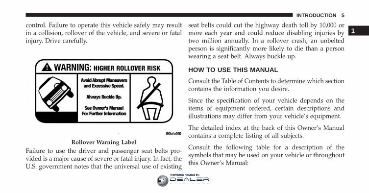
control. Failure to operate this vehicle safely may resultin a collision, rollover of the vehicle, and severe or fatalinjury. Drive carefully.
Failure to use the driver and passenger seat belts pro-vided is a major cause of severe or fatal injury. In fact, theU.S. government notes that the universal use of existing
seat belts could cut the highway death toll by 10,000 ormore each year and could reduce disabling injuries bytwo million annually. In a rollover crash, an unbeltedperson is significantly more likely to die than a personwearing a seat belt. Always buckle up.
HOW TO USE THIS MANUAL
Consult the Table of Contents to determine which sectioncontains the information you desire.
Since the specification of your vehicle depends on theitems of equipment ordered, certain descriptions andillustrations may differ from your vehicle’s equipment.
The detailed index at the back of this Owner’s Manualcontains a complete listing of all subjects.
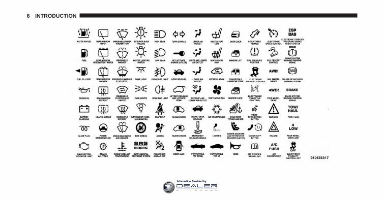
Consult the following table for a description of thesymbols that may be used on your vehicle or throughoutthis Owner’s Manual:
Rollover Warning Label
1
INTRODUCTION 5
Information Provided by:
6 INTRODUCTION
Information Provided by:
WARNINGS AND CAUTIONS
This Owner’s Manual contains WARNINGS against oper-ating procedures that could result in a collision or bodilyinjury. It also contains CAUTIONS against procedures thatcould result in damage to your vehicle. If you do not readthis entire Owner’s Manual, you may miss importantinformation. Observe all Warnings and Cautions.
VEHICLE IDENTIFICATION NUMBER
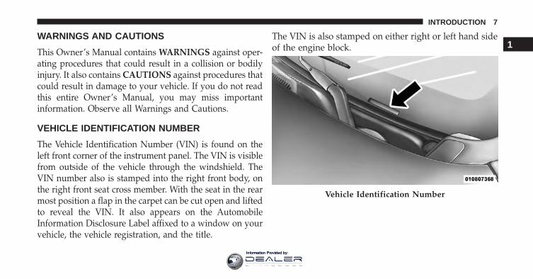
The Vehicle Identification Number (VIN) is found on theleft front corner of the instrument panel. The VIN is visiblefrom outside of the vehicle through the windshield. TheVIN number also is stamped into the right front body, onthe right front seat cross member. With the seat in the rearmost position a flap in the carpet can be cut open and liftedto reveal the VIN. It also appears on the AutomobileInformation Disclosure Label affixed to a window on yourvehicle, the vehicle registration, and the title.
The VIN is also stamped on either right or left hand sideof the engine block.
Vehicle Identification Number
1
INTRODUCTION 7
Information Provided by:
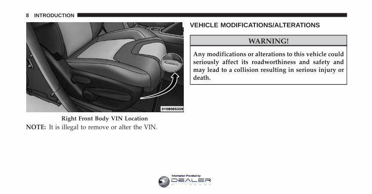
NOTE: It is illegal to remove or alter the VIN.
VEHICLE MODIFICATIONS/ALTERATIONS
WARNING!
Any modifications or alterations to this vehicle couldseriously affect its roadworthiness and safety andmay lead to a collision resulting in serious injury ordeath.
Right Front Body VIN Location
8 INTRODUCTION
Information Provided by:
THINGS TO KNOW BEFORE STARTING YOUR VEHICLE
CONTENTS� A WORD ABOUT YOUR KEYS . . . . . . . . . . . . .12
▫ Ignition Node Module (IGNM) — If Equipped. .12
▫ Keyless Push Button Ignition . . . . . . . . . . . . . .13
▫ Key Fob — If Equipped . . . . . . . . . . . . . . . . . .14
▫ Ignition Or Accessory On Message . . . . . . . . . .15
▫ General Information . . . . . . . . . . . . . . . . . . . .17
� SENTRY KEY . . . . . . . . . . . . . . . . . . . . . . . . . .17
▫ Replacement Keys . . . . . . . . . . . . . . . . . . . . .18
▫ Customer Key Programming . . . . . . . . . . . . . .19
▫ General Information . . . . . . . . . . . . . . . . . . . .19
� VEHICLE SECURITY ALARM — IFEQUIPPED . . . . . . . . . . . . . . . . . . . . . . . . . . . .19
▫ Rearming Of The System . . . . . . . . . . . . . . . .20
▫ To Arm The System . . . . . . . . . . . . . . . . . . . .20
▫ To Disarm The System . . . . . . . . . . . . . . . . . . .21
▫ Security System Manual Override . . . . . . . . . . .22
� ILLUMINATED ENTRY . . . . . . . . . . . . . . . . . . .22
� REMOTE KEYLESS ENTRY (RKE) . . . . . . . . . . .23
▫ To Unlock The Doors And Liftgate . . . . . . . . . .24
▫ To Lock The Doors And Liftgate . . . . . . . . . . . .25
2
Information Provided by:
▫ Using The Panic Alarm . . . . . . . . . . . . . . . . . .25
▫ Programming Additional Transmitters . . . . . . .26
▫ Transmitter Battery Replacement . . . . . . . . . . .26
▫ General Information . . . . . . . . . . . . . . . . . . . .29
� REMOTE STARTING SYSTEM — IFEQUIPPED . . . . . . . . . . . . . . . . . . . . . . . . . . . .30
▫ How To Use Remote Start . . . . . . . . . . . . . . . .30
▫ Remote Start Abort Message On Electronic VehicleInformation Center (EVIC) or Driver InformationDisplay (DID) — If Equipped . . . . . . . . . . . . . .31
▫ To Enter Remote Start Mode. . . . . . . . . . . . . . .32
▫ To Exit Remote Start Mode Without Driving TheVehicle . . . . . . . . . . . . . . . . . . . . . . . . . . . . .32
▫ To Exit Remote Start Mode And Drive TheVehicle . . . . . . . . . . . . . . . . . . . . . . . . . . . . . .32
▫ Remote Start Comfort Systems — IfEquipped . . . . . . . . . . . . . . . . . . . . . . . . . . .33
▫ Remote Start Windshield Wiper De–IcerActivation — If Equipped . . . . . . . . . . . . . . . .34
▫ General Information . . . . . . . . . . . . . . . . . . . .34
� DOOR LOCKS . . . . . . . . . . . . . . . . . . . . . . . . .34
▫ Manual Door Locks . . . . . . . . . . . . . . . . . . . . .34
▫ Power Door Locks . . . . . . . . . . . . . . . . . . . . .35
▫ Child-Protection Door Lock System — RearDoors . . . . . . . . . . . . . . . . . . . . . . . . . . . . . .37
� KEYLESS ENTER-N-GO . . . . . . . . . . . . . . . . . .39
▫ General Information . . . . . . . . . . . . . . . . . . . .44
� WINDOWS . . . . . . . . . . . . . . . . . . . . . . . . . . .45
▫ Power Windows . . . . . . . . . . . . . . . . . . . . . . .45
10 THINGS TO KNOW BEFORE STARTING YOUR VEHICLE
Information Provided by:
▫ Wind Buffeting . . . . . . . . . . . . . . . . . . . . . . .48
� LIFTGATE . . . . . . . . . . . . . . . . . . . . . . . . . . . .48
▫ Power Liftgate — If Equipped . . . . . . . . . . . . .50
� OCCUPANT RESTRAINT SYSTEMS . . . . . . . . . .52
▫ Important Safety Precautions . . . . . . . . . . . . . .53
▫ Seat Belt Systems . . . . . . . . . . . . . . . . . . . . . .54
▫ Supplemental Restraint System (SRS) . . . . . . . .66
▫ Child Restraints . . . . . . . . . . . . . . . . . . . . . . .91
▫ Transporting Pets . . . . . . . . . . . . . . . . . . . . .113
� ENGINE BREAK-IN RECOMMENDATIONS . . .113
� SAFETY TIPS . . . . . . . . . . . . . . . . . . . . . . . . .114
▫ Transporting Passengers . . . . . . . . . . . . . . . . .114
▫ Exhaust Gas . . . . . . . . . . . . . . . . . . . . . . . . .115
▫ Safety Checks You Should Make Inside TheVehicle . . . . . . . . . . . . . . . . . . . . . . . . . . . . .116
▫ Periodic Safety Checks You Should MakeOutside The Vehicle . . . . . . . . . . . . . . . . . . .118
2
THINGS TO KNOW BEFORE STARTING YOUR VEHICLE 11
Information Provided by:
A WORD ABOUT YOUR KEYS
Your vehicle uses either a key start ignition system orkeyless ignition system. The key start ignition systemconsists of a either a Key Fob with Remote Keyless Entry(RKE) transmitter and an Ignition Node Module (IGNM).The keyless ignition system consists of a Key Fob withRemote Keyless Entry (RKE) transmitter and a KeylessPush Button Ignition.
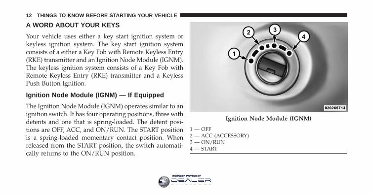
Ignition Node Module (IGNM) — If Equipped
The Ignition Node Module (IGNM) operates similar to anignition switch. It has four operating positions, three withdetents and one that is spring-loaded. The detent posi-tions are OFF, ACC, and ON/RUN. The START positionis a spring-loaded momentary contact position. Whenreleased from the START position, the switch automati-cally returns to the ON/RUN position.
Ignition Node Module (IGNM)
1 — OFF2 — ACC (ACCESSORY)3 — ON/RUN4 — START
12 THINGS TO KNOW BEFORE STARTING YOUR VEHICLE
Information Provided by:
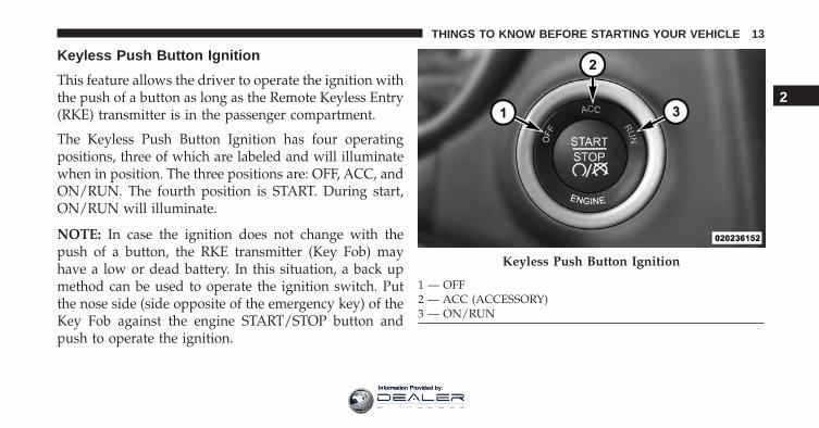
Keyless Push Button Ignition
This feature allows the driver to operate the ignition withthe push of a button as long as the Remote Keyless Entry(RKE) transmitter is in the passenger compartment.
The Keyless Push Button Ignition has four operatingpositions, three of which are labeled and will illuminatewhen in position. The three positions are: OFF, ACC, andON/RUN. The fourth position is START. During start,ON/RUN will illuminate.
NOTE: In case the ignition does not change with thepush of a button, the RKE transmitter (Key Fob) mayhave a low or dead battery. In this situation, a back upmethod can be used to operate the ignition switch. Putthe nose side (side opposite of the emergency key) of theKey Fob against the engine START/STOP button andpush to operate the ignition.
Keyless Push Button Ignition
1 — OFF2 — ACC (ACCESSORY)3 — ON/RUN
2
THINGS TO KNOW BEFORE STARTING YOUR VEHICLE 13
Information Provided by:
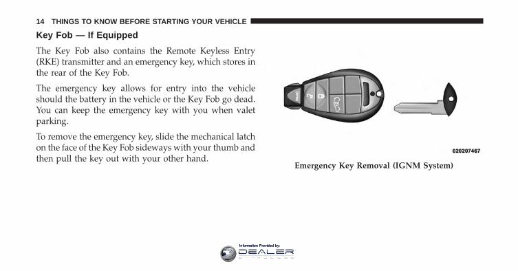
Key Fob — If Equipped
The Key Fob also contains the Remote Keyless Entry(RKE) transmitter and an emergency key, which stores inthe rear of the Key Fob.
The emergency key allows for entry into the vehicleshould the battery in the vehicle or the Key Fob go dead.You can keep the emergency key with you when valetparking.
To remove the emergency key, slide the mechanical latchon the face of the Key Fob sideways with your thumb andthen pull the key out with your other hand.
Emergency Key Removal (IGNM System)
14 THINGS TO KNOW BEFORE STARTING YOUR VEHICLE
Information Provided by:
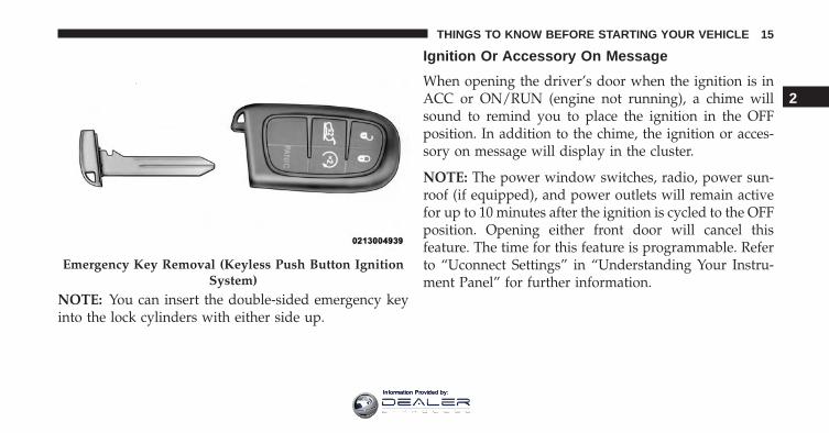
NOTE: You can insert the double-sided emergency keyinto the lock cylinders with either side up.
Ignition Or Accessory On Message
When opening the driver’s door when the ignition is inACC or ON/RUN (engine not running), a chime willsound to remind you to place the ignition in the OFFposition. In addition to the chime, the ignition or acces-sory on message will display in the cluster.
NOTE: The power window switches, radio, power sun-roof (if equipped), and power outlets will remain activefor up to 10 minutes after the ignition is cycled to the OFFposition. Opening either front door will cancel thisfeature. The time for this feature is programmable. Referto “Uconnect Settings” in “Understanding Your Instru-ment Panel” for further information.
Emergency Key Removal (Keyless Push Button IgnitionSystem)
2
THINGS TO KNOW BEFORE STARTING YOUR VEHICLE 15
Information Provided by:
WARNING!
• When leaving the vehicle, always remove the KeyFob from the vehicle and lock your vehicle. Ifequipped with Keyless Enter-N-Go, always makesure the keyless ignition node is in “OFF” mode,remove the Key Fob from the vehicle and lock thevehicle.
• Never leave children alone in a vehicle, or withaccess to an unlocked vehicle.
• Allowing children to be in a vehicle unattended isdangerous for a number of reasons. A child orothers could be seriously or fatally injured. Chil-dren should be warned not to touch the parkingbrake, brake pedal or the gear selector.
• Do not leave the Key Fob in or near the vehicle, orin a location accessible to children, and do notleave the ignition of a vehicle equipped with
(Continued)
WARNING! (Continued)Keyless Enter-N-Go in the ACC or ON/RUN mode.A child could operate power windows, other con-trols, or move the vehicle.
• Do not leave children or animals inside parkedvehicles in hot weather. Interior heat build-up maycause serious injury or death.
CAUTION!
An unlocked car is an invitation to thieves. Alwaysremove key from the ignition and lock all doorswhen leaving the vehicle unattended.
16 THINGS TO KNOW BEFORE STARTING YOUR VEHICLE
Information Provided by:
General Information
The following regulatory statement applies to all radiofrequency (RF) devices equipped in this vehicle:
This device complies with Part 15 of the FCC Rules andwith Industry Canada licence-exempt RSS standard(s).Operation is subject to the following two conditions:
1. This device may not cause harmful interference, and
2. This device must accept any interference received,including interference that may cause undesired op-eration.
NOTE: Changes or modifications not expressly approvedby the party responsible for compliance could void theuser’s authority to operate the equipment.
SENTRY KEY
The Sentry Key Immobilizer system prevents unauthor-ized vehicle operation by disabling the engine. Thesystem does not need to be armed or activated. Operationis automatic, regardless of whether the vehicle is lockedor unlocked.
The system uses a Key Fob with a factory-mated RemoteKeyless Entry (RKE) transmitter, a Keyless Push ButtonIgnition and a RF receiver to prevent unauthorizedvehicle operation. Therefore, only Key Fobs that areprogrammed to the vehicle can be used to start andoperate the vehicle. The system will not allow the engineto crank with an invalid Key Fob.
After placing the ignition to the ON/RUN position, theVehicle Security Light will turn on for three seconds for abulb check. If the light remains on after the bulb check, itindicates that there is a problem with the system. Inaddition, if the light begins to flash after the bulb check,
2
THINGS TO KNOW BEFORE STARTING YOUR VEHICLE 17
Information Provided by:
it indicates that someone tried to use an invalid Key Fobto start the engine. Either of these conditions will result inthe engine being shut off after two seconds.
If the Vehicle Security Light turns on during normalvehicle operation (vehicle running for longer than 10seconds), it indicates that there is a fault in the system.Should this occur, have the vehicle serviced as soon aspossible by an authorized dealer.
CAUTION!
• Do not make modifications or alterations to theimmobilizer system. Modifications or alterations tothe immobilization system may result in a loss ofsecurity protection.
• The Sentry Key Immobilizer system is not compat-ible with some aftermarket remote starting sys-tems. Use of these systems may result in vehiclestarting problems and loss of security protection.
All of the Key Fobs provided with your new vehicle havebeen programmed to the vehicle electronics.
Replacement Keys
NOTE: Only Key Fobs that are programmed to thevehicle electronics can be used to start and operate thevehicle. Once a Key Fob is programmed to a vehicle, itcannot be programmed to any other vehicle.
CAUTION!
• Always remove the Key Fobs from the vehicle andlock all doors when leaving the vehicle unat-tended.
• For vehicles equipped with Keyless Enter-N-Go,always remember to place the ignition in the OFFposition.
18 THINGS TO KNOW BEFORE STARTING YOUR VEHICLE
Information Provided by:
NOTE: Duplication of Key Fobs may be performed at anauthorized dealer. This procedure consists of program-ming a blank Key Fob to the vehicle electronics. A blankKey Fob is one that has never been programmed.
When having the Sentry Key Immobilizer System serviced,bring all vehicle keys with you to an authorized dealer.
Customer Key Programming
Programming Key Fobs or RKE transmitters may beperformed at an authorized dealer.
General Information
The following regulatory statement applies to all radiofrequency (RF) devices equipped in this vehicle:
This device complies with Part 15 of the FCC Rules andwith Industry Canada licence-exempt RSS standard(s).Operation is subject to the following two conditions:
1. This device may not cause harmful interference, and
2. This device must accept any interference received,including interference that may cause undesired op-eration.
NOTE: Changes or modifications not expressly approvedby the party responsible for compliance could void theuser’s authority to operate the equipment.
VEHICLE SECURITY ALARM — IF EQUIPPED
The Vehicle Security Alarm monitors the vehicle doorsfor unauthorized entry and the Keyless Enter-N-GoStart/Stop button for unauthorized operation. While theVehicle Security Alarm is armed, interior switches fordoor locks and liftgate release are disabled.
If something triggers the alarm, the Vehicle SecurityAlarm will provide the following audible and visiblesignals:
• The horn will pulse.
2
THINGS TO KNOW BEFORE STARTING YOUR VEHICLE 19
Information Provided by:
• The park lamps and/or turn signals will flash.
• The Vehicle Security Light in the instrument clusterwill flash.
Rearming Of The System
If something triggers the alarm, and no action is taken todisarm it, the Vehicle Security Alarm will turn the hornoff after three minutes, turn all of the visual signals offafter 15 additional minutes, and then the Vehicle SecurityAlarm will rearm itself.
To Arm The System
Follow these steps to arm the Vehicle Security Alarm:
1. Make sure the vehicles ignition is cycled to the “OFF”position (refer to �Starting Procedures� in �StartingAnd Operating� for further information).• For vehicles equipped with Keyless Enter-N-Go,
make sure the vehicle ignition system is OFF.
• For vehicles not equipped with Keyless Enter-N-Go,make sure the vehicle ignition system is OFF, and thekey is physically removed from the ignition.
2. Perform one of the following methods to lock thevehicle:• Push LOCK on the interior power door lock switch
with the driver and/or passenger door open.• Push the LOCK button on the exterior Passive Entry
Door Handle with a valid Key Fob available in thesame exterior zone (refer to �Keyless Enter-N-Go� in�Things To Know Before Starting Your Vehicle� forfurther information).
• Push the LOCK button on the Remote Keyless Entry(RKE) transmitter.
3. If any doors are open, close them.
20 THINGS TO KNOW BEFORE STARTING YOUR VEHICLE
Information Provided by:
To Disarm The System
The Vehicle Security Alarm can be disarmed using any ofthe following methods:
• Push the UNLOCK button on the Remote KeylessEntry (RKE) transmitter.
• Grasp the Passive Entry Unlock Door Handle with avalid Key Fob available in the same exterior zone (ifequipped). Refer to �Keyless Enter-N-Go� in �Things ToKnow Before Starting Your Vehicle� for further infor-mation.
• Cycle the vehicle ignition system out of the OFFposition.• For vehicles equipped with Keyless Enter-N-Go,
push the Keyless Enter-N-Go Start/Stop button (re-quires at least one valid Key Fob in the vehicle).
• For vehicles not equipped with Keyless Enter-N-Go,insert a valid key into the ignition switch and turnthe key to the ON position.
NOTE:
• The driver’s door key cylinder and the liftgate buttonon the RKE transmitter cannot arm or disarm theVehicle Security Alarm.
• The Vehicle Security Alarm remains armed duringpower liftgate entry. Pushing the liftgate button willnot disarm the Vehicle Security Alarm. If someoneenters the vehicle through the liftgate and opens anydoor, the alarm will sound.
• When the Vehicle Security Alarm is armed, the interiorpower door lock switches will not unlock the doors.
The Vehicle Security Alarm is designed to protect yourvehicle. However, you can create conditions where the
2
THINGS TO KNOW BEFORE STARTING YOUR VEHICLE 21
Information Provided by:
system will give you a false alarm. If one of the previ-ously described arming sequences has occurred, theVehicle Security Alarm will arm regardless of whetheryou are in the vehicle or not. If you remain in the vehicleand open a door, the alarm will sound. If this occurs,disarm the Vehicle Security Alarm.
If the Vehicle Security Alarm is armed and the batterybecomes disconnected, the Vehicle Security Alarm willremain armed when the battery is reconnected; theexterior lights will flash and the horn will sound. If thisoccurs, disarm the Vehicle Security Alarm.
Security System Manual Override
The Vehicle Security Alarm will not arm if you lock thedoors using the manual door lock plunger.
ILLUMINATED ENTRY
The courtesy lights will turn on when you use theRemote Keyless Entry (RKE) transmitter to unlock thedoors or open any door.
This feature also turns on the approach lighting in theoutside mirrors — if equipped. Refer to “Mirrors” in“Understanding The Features Of Your Vehicle” for fur-ther information.
The lights will fade to off after approximately 30 seconds,or they will immediately fade to off once the ignitionswitch is turned to ON/RUN from the OFF position.
22 THINGS TO KNOW BEFORE STARTING YOUR VEHICLE
Information Provided by:
NOTE:
• The front courtesy overhead console and door cour-tesy lights do not turn on if the dimmer control is inthe “Dome defeat” position (extreme bottom position).
• The Illuminated Entry system will not operate if thedimmer control is in the “Dome defeat” position(extreme bottom position).
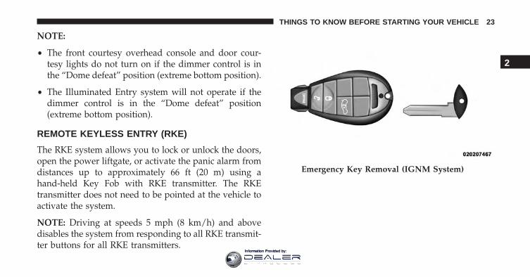
REMOTE KEYLESS ENTRY (RKE)
The RKE system allows you to lock or unlock the doors,open the power liftgate, or activate the panic alarm fromdistances up to approximately 66 ft (20 m) using ahand-held Key Fob with RKE transmitter. The RKEtransmitter does not need to be pointed at the vehicle toactivate the system.
NOTE: Driving at speeds 5 mph (8 km/h) and abovedisables the system from responding to all RKE transmit-ter buttons for all RKE transmitters.
Emergency Key Removal (IGNM System)
2
THINGS TO KNOW BEFORE STARTING YOUR VEHICLE 23
Information Provided by:
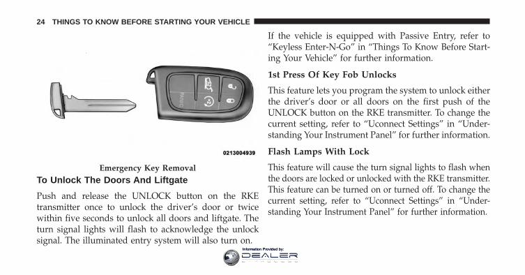
To Unlock The Doors And Liftgate
Push and release the UNLOCK button on the RKEtransmitter once to unlock the driver’s door or twicewithin five seconds to unlock all doors and liftgate. Theturn signal lights will flash to acknowledge the unlocksignal. The illuminated entry system will also turn on.
If the vehicle is equipped with Passive Entry, refer to“Keyless Enter-N-Go” in “Things To Know Before Start-ing Your Vehicle” for further information.
1st Press Of Key Fob Unlocks
This feature lets you program the system to unlock eitherthe driver’s door or all doors on the first push of theUNLOCK button on the RKE transmitter. To change thecurrent setting, refer to “Uconnect Settings” in “Under-standing Your Instrument Panel” for further information.
Flash Lamps With Lock
This feature will cause the turn signal lights to flash whenthe doors are locked or unlocked with the RKE transmitter.This feature can be turned on or turned off. To change thecurrent setting, refer to “Uconnect Settings” in “Under-standing Your Instrument Panel” for further information.
Emergency Key Removal
24 THINGS TO KNOW BEFORE STARTING YOUR VEHICLE
Information Provided by:
Headlight Illumination On Approach
This feature activates the headlights for up to 90 secondswhen the doors are unlocked with the RKE transmitter.The time for this feature is programmable on vehiclesequipped through Uconnect. To change the current set-ting, refer to “Uconnect Settings” in “UnderstandingYour Instrument Panel” for further information.
To Lock The Doors And Liftgate
Push and release the LOCK button on the RKE transmit-ter to lock all doors and liftgate. The turn signal lightswill flash, and the horn will chirp to acknowledge thesignal.
If the vehicle is equipped with Passive Entry, refer to“Keyless Enter-N-Go” in “Things To Know Before Start-ing Your Vehicle” for further information.
Sound Horn With Lock
This feature will cause the horn to chirp when the doorsare locked with the RKE transmitter. This feature can beturned on or turned off. To change the current setting,refer to “Uconnect Settings” in “Understanding YourInstrument Panel” for further information.
Using The Panic Alarm
To turn the Panic Alarm feature on or off, push and holdthe PANIC button on the RKE transmitter for at least onesecond and release. When the Panic Alarm is activated,the turn signals will flash, the horn will pulse on and off,and the interior lights will turn on.
The Panic Alarm will stay on for three minutes unlessyou turn it off by either pushing the PANIC button asecond time or drive the vehicle at a speed of 15 MPH(24 km/h) or greater.
2
THINGS TO KNOW BEFORE STARTING YOUR VEHICLE 25
Information Provided by:
NOTE:
• The interior lights will turn off if you place the ignitionin the ACC or ON/RUN position while the PanicAlarm is activated. However, the exterior lights andhorn will remain on.
• You may need to be less than 35 ft (11 m) from thevehicle when using the RKE transmitter to turn off thePanic Alarm due to the radio frequency noises emittedby the system.
Programming Additional Transmitters
Programming Key Fobs or RKE transmitters may beperformed at an authorized dealer.
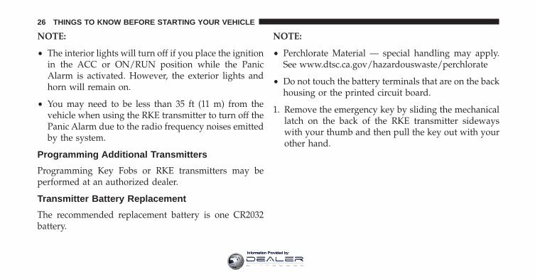
Transmitter Battery Replacement
The recommended replacement battery is one CR2032battery.
NOTE:
• Perchlorate Material — special handling may apply.See www.dtsc.ca.gov/hazardouswaste/perchlorate
• Do not touch the battery terminals that are on the backhousing or the printed circuit board.
1. Remove the emergency key by sliding the mechanicallatch on the back of the RKE transmitter sidewayswith your thumb and then pull the key out with yourother hand.
26 THINGS TO KNOW BEFORE STARTING YOUR VEHICLE
Information Provided by:
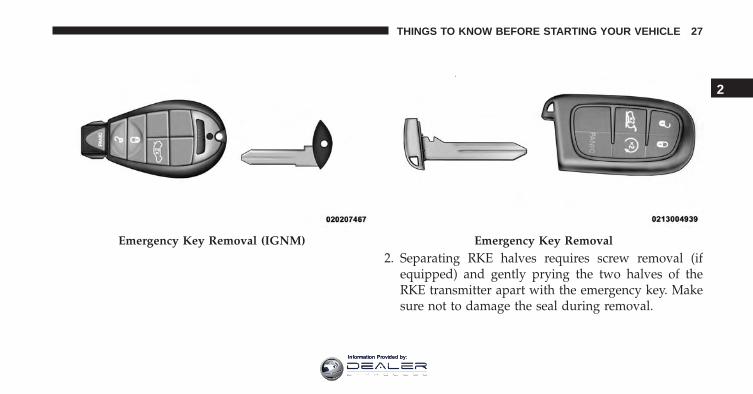
2. Separating RKE halves requires screw removal (ifequipped) and gently prying the two halves of theRKE transmitter apart with the emergency key. Makesure not to damage the seal during removal.
Emergency Key Removal (IGNM) Emergency Key Removal
2
THINGS TO KNOW BEFORE STARTING YOUR VEHICLE 27
Information Provided by:
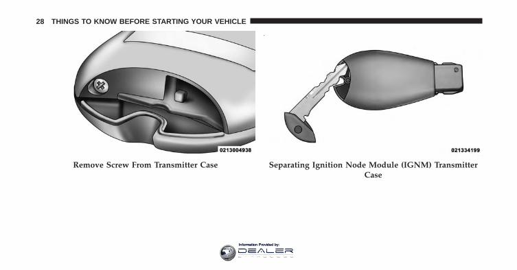
Remove Screw From Transmitter Case Separating Ignition Node Module (IGNM) TransmitterCase
28 THINGS TO KNOW BEFORE STARTING YOUR VEHICLE
Information Provided by:
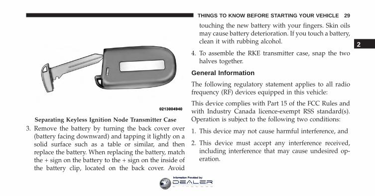
3. Remove the battery by turning the back cover over(battery facing downward) and tapping it lightly on asolid surface such as a table or similar, and thenreplace the battery. When replacing the battery, matchthe + sign on the battery to the + sign on the inside ofthe battery clip, located on the back cover. Avoid
touching the new battery with your fingers. Skin oilsmay cause battery deterioration. If you touch a battery,clean it with rubbing alcohol.
4. To assemble the RKE transmitter case, snap the twohalves together.
General Information
The following regulatory statement applies to all radiofrequency (RF) devices equipped in this vehicle:
This device complies with Part 15 of the FCC Rules andwith Industry Canada licence-exempt RSS standard(s).Operation is subject to the following two conditions:
1. This device may not cause harmful interference, and
2. This device must accept any interference received,including interference that may cause undesired op-eration.
Separating Keyless Ignition Node Transmitter Case
2
THINGS TO KNOW BEFORE STARTING YOUR VEHICLE 29
Information Provided by:
NOTE: Changes or modifications not expressly approvedby the party responsible for compliance could void theuser’s authority to operate the equipment.
REMOTE STARTING SYSTEM — IF EQUIPPED
This system uses the Remote Keyless Entry(RKE) transmitter to start the engine conve-niently from outside the vehicle while stillmaintaining security. The system has a range of
approximately 300 ft (91 m).
NOTE:
• The vehicle must be equipped with an automatictransmission to be equipped with Remote Start.
• Obstructions between the vehicle and RKE transmittermay reduce this range.
How To Use Remote Start
All of the following conditions must be met before theengine will remote start:
• Shift Lever in PARK
• Doors closed
• Hood closed
• Liftgate closed
• Hazard switch off
• Brake switch inactive (brake pedal not pushed)
• Battery at an acceptable charge level
• RKE PANIC button not pushed
• System not disabled from previous remote start event
30 THINGS TO KNOW BEFORE STARTING YOUR VEHICLE
Information Provided by:
• Vehicle alarm system indicator flashing
• Ignition in STOP/OFF position
• Fuel level meets minimum requirement
WARNING!
• Do not start or run an engine in a closed garage orconfined area. Exhaust gas contains Carbon Mon-oxide (CO) which is odorless and colorless. CarbonMonoxide is poisonous and can cause serious in-jury or death when inhaled.
• Keep Remote Keyless Entry (RKE) transmittersaway from children. Operation of the Remote StartSystem, windows, door locks or other controlscould cause serious injury or death.
Remote Start Abort Message On ElectronicVehicle Information Center (EVIC) or DriverInformation Display (DID) — If Equipped
The following messages will display in the EVIC/DID ifthe vehicle fails to remote start or exits remote startprematurely:
• Remote Start Aborted — Door Open
• Remote Start Aborted — Hood Open
• Remote Start Aborted — Fuel Low
• Remote Start Aborted — Liftgate Open
• Remote Start Disabled — Start Vehicle To Reset
• Remote Start Aborted — Too Cold
• Remote Start Aborted — Time Expired
The message will stay active until the ignition is turned tothe ON/RUN position.
2
THINGS TO KNOW BEFORE STARTING YOUR VEHICLE 31
Information Provided by:
To Enter Remote Start Mode
Push and release the REMOTE START button on theRKE transmitter twice within five seconds. The vehicledoors will lock, the parking lights will flash, and thehorn will chirp twice (if programmed). Then, theengine will start, and the vehicle will remain in theRemote Start mode for a 15-minute cycle.
NOTE:
• If an engine fault is present or fuel level is low, thevehicle will start and then shut down in 10 seconds.
• The park lamps will turn on and remain on duringRemote Start mode.
• For security, power window and power sunroof op-eration (if equipped) are disabled when the vehicle isin the Remote Start mode.
• The engine can be started two consecutive times withthe RKE transmitter. However, the ignition must becycled by pushing the START/STOP button twice (orthe ignition switch must be cycled to the ON/RUNposition) before you can repeat the start sequence for athird cycle.
To Exit Remote Start Mode Without Driving TheVehicle
Push and release the REMOTE START button one time orallow the engine to run for the entire 15-minute cycle.
NOTE: To avoid unintentional shutdowns, the systemwill disable the one time push of the REMOTE STARTbutton for two seconds after receiving a valid RemoteStart request.
To Exit Remote Start Mode And Drive The Vehicle
Before the end of 15-minute cycle, push and release theUNLOCK button on the RKE transmitter to unlock the
32 THINGS TO KNOW BEFORE STARTING YOUR VEHICLE
Information Provided by:
doors and disarm the Vehicle Security Alarm (ifequipped). Then, prior to the end of the 15-minute cycle,push and release the START/STOP button. If the START/STOP button is not present, insert the Key Fob into theignition switch and turn the switch to the ON/RUNposition.
NOTE:
• For vehicles not equipped with the Keyless Enter-N-Go feature, the ignition switch must be in theON/RUN position in order to drive the vehicle.
• For vehicles not equipped with the Keyless Enter-N-Go feature, the message “Remote Start Active —Insert Key and Turn To Run” will display in theEVIC/DID until you insert the key. Refer to “Elec-tronic Vehicle Information Center (EVIC)” or “DriverInformation Display” in “Understanding Your Instru-ment Panel” for further information.
• For vehicles equipped with the Keyless Enter-N-Gofeature, the message “Remote Start Active — PushStart Button” will display in the EVIC/DID until youpush the START button.
Remote Start Comfort Systems — If Equipped
When remote start is activated, the heated steering wheeland driver heated seat features will automatically turn onin cold weather. In warm weather, the driver vented seatfeature will automatically turn on when the remote startis activated. These features will stay on through theduration of remote start or until the ignition switch iscycled to the ON/RUN position.
NOTE: The Remote Start Comfort System can be acti-vated and deactivated through the Uconnect Settings. Formore information on Remote Start Comfort System op-eration, refer to “Uconnect Settings” in “UnderstandingYour Instrument Panel.”
2
THINGS TO KNOW BEFORE STARTING YOUR VEHICLE 33
Information Provided by:
Remote Start Windshield Wiper De–IcerActivation — If Equipped
When Remote Start is active and the outside ambienttemperature is less than 40° F (4.4° C), the WindshieldWiper De-Icer will be enabled. Exiting Remote Start willresume previous operation, except if the WindshieldWiper De-Icer is active. The Windshield Wiper De-Icertimer and operation will continue.
General Information
The following regulatory statement applies to all radiofrequency (RF) devices equipped in this vehicle:
This device complies with Part 15 of the FCC Rules andwith Industry Canada licence-exempt RSS standard(s).Operation is subject to the following two conditions:
1. This device may not cause harmful interference, and
2. This device must accept any interference received, in-cluding interference that may cause undesired operation.
NOTE: Changes or modifications not expressly approvedby the party responsible for compliance could void theuser’s authority to operate the equipment.
DOOR LOCKS
Manual Door Locks
To lock each door, rotate the door lock knob on each doortrim panel forward. To unlock the front doors, pull theinside door handle to the first detent or rotate the doorlock button until the red indicator is visible. To unlock therear doors, rotate the door lock button until the redindicator is visible.
If the door lock button is locked (no red indicator visible)when you shut the door, the door will lock. Therefore,make sure the Key Fob is not inside the vehicle beforeclosing the door.
34 THINGS TO KNOW BEFORE STARTING YOUR VEHICLE
Information Provided by:
NOTE: The manual door locks will not lock or unlockthe liftgate.
WARNING!
• For personal security and safety in the event of acollision, lock the vehicle doors before you drive aswell as when you park and leave the vehicle.
• When leaving the vehicle, always remove the KeyFob from the vehicle and lock your vehicle. Ifequipped with Keyless Enter-N-Go, always makesure the keyless ignition node is in “OFF” mode,remove the Key Fob from the vehicle and lock thevehicle. Unsupervised use of vehicle equipmentmay cause severe personal injuries or death.
• Never leave children alone in a vehicle, or withaccess to an unlocked vehicle. Allowing children tobe in a vehicle unattended is dangerous for a
(Continued)
WARNING! (Continued)number of reasons. A child or others could beseriously or fatally injured. Children should bewarned not to touch the parking brake, brake pedalor the gear selector.
• Do not leave the Key Fob in or near the vehicle, orin a location accessible to children, and do notleave the ignition of a vehicle equipped withKeyless Enter-N-Go in the ACC or ON/RUN mode.A child could operate power windows, other con-trols, or move the vehicle.
Power Door Locks
A power door lock switch is located on each of the frontdoor trim panels. Use this switch to lock or unlock thedoors and liftgate.
2
THINGS TO KNOW BEFORE STARTING YOUR VEHICLE 35
Information Provided by:
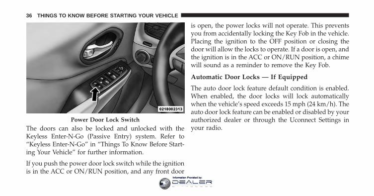
The doors can also be locked and unlocked with theKeyless Enter-N-Go (Passive Entry) system. Refer to“Keyless Enter-N-Go” in “Things To Know Before Start-ing Your Vehicle” for further information.
If you push the power door lock switch while the ignitionis in the ACC or ON/RUN position, and any front door
is open, the power locks will not operate. This preventsyou from accidentally locking the Key Fob in the vehicle.Placing the ignition to the OFF position or closing thedoor will allow the locks to operate. If a door is open, andthe ignition is in the ACC or ON/RUN position, a chimewill sound as a reminder to remove the Key Fob.
Automatic Door Locks — If Equipped
The auto door lock feature default condition is enabled.When enabled, the door locks will lock automaticallywhen the vehicle’s speed exceeds 15 mph (24 km/h). Theauto door lock feature can be enabled or disabled by yourauthorized dealer or through the Uconnect Settings inyour radio.
Power Door Lock Switch
36 THINGS TO KNOW BEFORE STARTING YOUR VEHICLE
Information Provided by:
Automatic Unlock Doors On Exit
The doors will unlock automatically on vehicles withpower door locks if:
1. The Automatic Unlock Doors On Exit feature is en-abled.
2. All doors are closed.
3. The transmission shift lever was not in PARK, then isplaced in PARK.
4. Any door is opened.
Automatic Unlock Doors On Exit Programming
To change the current setting, refer to “Uconnect Set-tings” in “Understanding Your Instrument Panel” forfurther information.
NOTE: Use the Automatic Unlock Doors On Exit featurein accordance with local laws.
Child-Protection Door Lock System — RearDoors
To provide a safer environment for small children ridingin the rear seats, the rear doors are equipped with aChild-Protection Door Lock system.
To use the system, open each rear door, use a flat bladescrewdriver (or ignition key) and rotate the dial to theLOCK or UNLOCK position. When the system on a dooris engaged, that door can only be opened by using theoutside door handle even if the inside door lock is in theunlocked position.
2
THINGS TO KNOW BEFORE STARTING YOUR VEHICLE 37
Information Provided by:
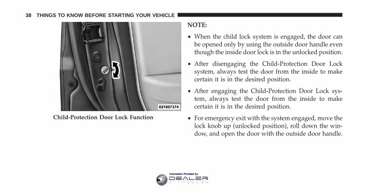
NOTE:
• When the child lock system is engaged, the door canbe opened only by using the outside door handle eventhough the inside door lock is in the unlocked position.
• After disengaging the Child-Protection Door Locksystem, always test the door from the inside to makecertain it is in the desired position.
• After engaging the Child-Protection Door Lock sys-tem, always test the door from the inside to makecertain it is in the desired position.
• For emergency exit with the system engaged, move thelock knob up (unlocked position), roll down the win-dow, and open the door with the outside door handle.
Child-Protection Door Lock Function
38 THINGS TO KNOW BEFORE STARTING YOUR VEHICLE
Information Provided by:
WARNING!
Avoid trapping anyone in a vehicle in a collision.Remember that the rear doors can only be openedfrom the outside when the Child-Protection locks areengaged.
KEYLESS ENTER-N-GO
The Passive Entry system is an enhancement to thevehicle’s Remote Keyless Entry (RKE) system and afeature of Keyless Enter-N-Go. This feature allows you tolock and unlock the vehicle’s door(s) without having topush the RKE transmitter lock or unlock buttons.
NOTE:
• Passive Entry may be programmed ON/OFF; refer to“Uconnect Settings” in “Understanding Your Instru-ment Panel” for further information.
• If wearing gloves on your hands, or if it has beenraining on the Passive Entry door handle, the unlocksensitivity can be affected, resulting in a slower re-sponse time.
• If the vehicle is unlocked by Passive Entry and no dooris opened within 60 seconds, the vehicle will re-lockand if equipped will arm the security alarm.
To Unlock From The Driver’s Side
With a valid Passive Entry RKE transmitter within 5 ft(1.5 m) of the driver’s door handle, grab the front driverdoor handle to unlock the driver’s door automatically.
2
THINGS TO KNOW BEFORE STARTING YOUR VEHICLE 39
Information Provided by:
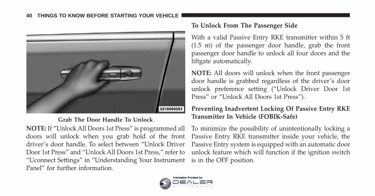
NOTE: If “Unlock All Doors 1st Press” is programmed alldoors will unlock when you grab hold of the frontdriver’s door handle. To select between “Unlock DriverDoor 1st Press” and “Unlock All Doors 1st Press,” refer to“Uconnect Settings” in “Understanding Your InstrumentPanel” for further information.
To Unlock From The Passenger Side
With a valid Passive Entry RKE transmitter within 5 ft(1.5 m) of the passenger door handle, grab the frontpassenger door handle to unlock all four doors and theliftgate automatically.
NOTE: All doors will unlock when the front passengerdoor handle is grabbed regardless of the driver’s doorunlock preference setting (“Unlock Driver Door 1stPress” or “Unlock All Doors 1st Press”).
Preventing Inadvertent Locking Of Passive Entry RKETransmitter In Vehicle (FOBIK-Safe)
To minimize the possibility of unintentionally locking aPassive Entry RKE transmitter inside your vehicle, thePassive Entry system is equipped with an automatic doorunlock feature which will function if the ignition switchis in the OFF position.
Grab The Door Handle To Unlock
40 THINGS TO KNOW BEFORE STARTING YOUR VEHICLE
Information Provided by:
FOBIK-Safe only executes in vehicles with passive entry.There are three situations that trigger a FOBIK-Safesearch in any passive entry vehicle:
• A lock request is made by a valid Passive Entry RKEtransmitter while a door is open.
• A lock request is made by the Passive Entry doorhandle while a door is open.
• A lock request is made by the door panel switch whilethe door is open.
When any of these situations occur, after all open doorsare shut, the FOBIK-Safe search will be executed. If itfinds a Passive Entry RKE transmitter inside the car, andit does not find any Passive Entry RKE transmittersoutside the car, then the car will unlock and alert thecustomer.
NOTE: The vehicle will only unlock the doors when avalid Passive Entry RKE transmitter is detected inside thevehicle, and no valid Passive Entry RKE transmitter isdetected outside the vehicle. The vehicle will not unlockthe doors when any of the following conditions are true:
• The doors are manually locked using the door lockknobs.
• There is a valid Passive Entry RKE transmitter outsidethe vehicle and within 5 ft (1.5 m) of either PassiveEntry door handle.
• Three attempts are made to lock the doors using thedoor panel switch and then close the doors.
To Unlock/Enter The Liftgate
The liftgate passive entry unlock feature is built into theelectronic liftgate release. With a valid Passive Entry RKEtransmitter within 3 ft (1.0 m) of the liftgate, push theelectronic liftgate release to open with one fluid motion.
2
THINGS TO KNOW BEFORE STARTING YOUR VEHICLE 41
Information Provided by:
NOTE: If “Unlock All Doors 1st Press” is programmed inEVIC/DID (if equipped), all doors will unlock when youpush the electronic release on the liftgate. If �UnlockDriver Door 1st Press� is programmed in Uconnect, theliftgate will unlock when you push the electronic releaseon the liftgate. Refer to “Uconnect” in “UnderstandingYour Instrument Panel” for further information.
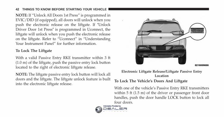
To Lock The Liftgate
With a valid Passive Entry RKE transmitter within 3 ft(1.0 m) of the liftgate, push the passive entry lock buttonlocated to the right of electronic liftgate release.
NOTE: The liftgate passive entry lock button will lock alldoors and the liftgate. The liftgate unlock feature is builtinto the electronic liftgate release.
To Lock The Vehicle’s Doors And Liftgate
With one of the vehicle’s Passive Entry RKE transmitterswithin 5 ft (1.5 m) of the driver or passenger front doorhandles, push the door handle LOCK button to lock allfour doors.
Electronic Liftgate Release/Liftgate Passive EntryLocation
42 THINGS TO KNOW BEFORE STARTING YOUR VEHICLE
Information Provided by:
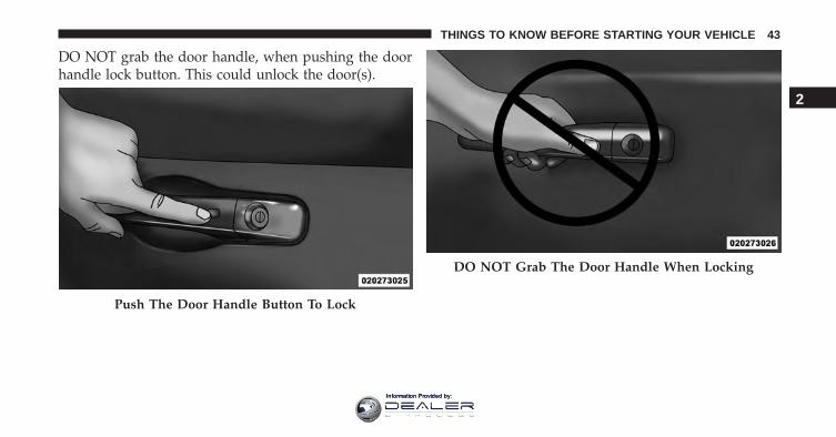
DO NOT grab the door handle, when pushing the doorhandle lock button. This could unlock the door(s).
Push The Door Handle Button To Lock
DO NOT Grab The Door Handle When Locking
2
THINGS TO KNOW BEFORE STARTING YOUR VEHICLE 43
Information Provided by:
NOTE:
• After pushing the door handle button, you must waittwo seconds before you can lock or unlock the doors,using either Passive Entry door handle. This is done toallow you to check if the vehicle is locked by pullingthe door handle without the vehicle reacting andunlocking.
• If Passive Entry is disabled using Uconnect System, thekey protection described in �Preventing InadvertentLocking of Passive Entry RKE Transmitter in Vehicle�remains active/functional.
• The Passive Entry system will not operate if the RKEtransmitter battery is dead.
The vehicle doors can also be locked by using the lockbutton located on the vehicle’s interior door panel.
General Information
The following regulatory statement applies to all radiofrequency (RF) devices equipped in this vehicle:
This device complies with Part 15 of the FCC Rules andwith Industry Canada licence-exempt RSS standard(s).Operation is subject to the following two conditions:
1. This device may not cause harmful interference, and
2. This device must accept any interference received,including interference that may cause undesired op-eration.
NOTE: Changes or modifications not expressly approvedby the party responsible for compliance could void theuser’s authority to operate the equipment.
44 THINGS TO KNOW BEFORE STARTING YOUR VEHICLE
Information Provided by:
WINDOWS
Power Windows
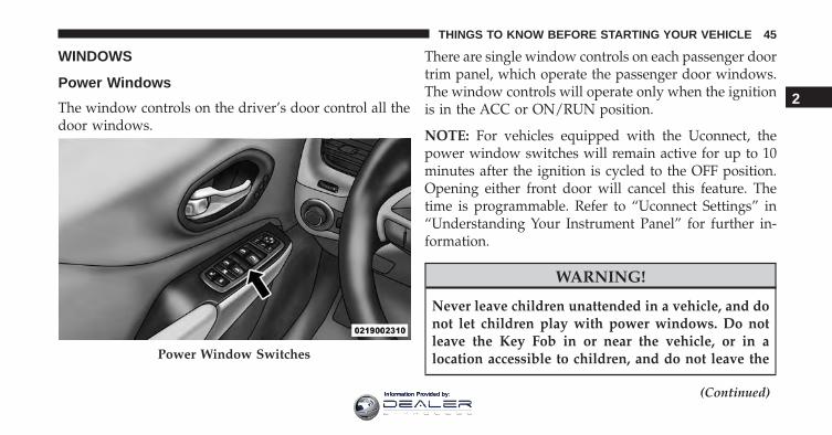
The window controls on the driver’s door control all thedoor windows.
There are single window controls on each passenger doortrim panel, which operate the passenger door windows.The window controls will operate only when the ignitionis in the ACC or ON/RUN position.
NOTE: For vehicles equipped with the Uconnect, thepower window switches will remain active for up to 10minutes after the ignition is cycled to the OFF position.Opening either front door will cancel this feature. Thetime is programmable. Refer to “Uconnect Settings” in“Understanding Your Instrument Panel” for further in-formation.
WARNING!
Never leave children unattended in a vehicle, and donot let children play with power windows. Do notleave the Key Fob in or near the vehicle, or in alocation accessible to children, and do not leave the
(Continued)
Power Window Switches
2
THINGS TO KNOW BEFORE STARTING YOUR VEHICLE 45
Information Provided by:
WARNING! (Continued)ignition of a vehicle equipped with Keyless Enter-N-Go in the ACC or ON/RUN mode. Occupants,particularly unattended children, can become en-trapped by the windows while operating the powerwindow switches. Such entrapment may result inserious injury or death.
AUTO-Down Feature
The driver door power window switch and some modelpassenger door power window switches have an AUTO-Down feature. Push the window switch to the seconddetent, release, and the window will go down automati-cally.
To open the window part way, push the window switchto the first detent and release it when you want thewindow to stop.
To stop the window from going all the way down duringthe AUTO-Down operation, pull up on the switch briefly.
AUTO-Up Feature With Anti-Pinch Protection
Lift the window switch to the second detent, release, andthe window will go up automatically.
To stop the window from going all the way up during theAUTO-Up operation, push down on the switch briefly.
To close the window part way, lift the window switch tothe first detent and release it when you want the windowto stop.
NOTE:
• If the window runs into any obstacle during auto-closure, it will reverse direction and then go backdown. Remove the obstacle and use the windowswitch again to close the window.
46 THINGS TO KNOW BEFORE STARTING YOUR VEHICLE
Information Provided by:
• Any impact due to rough road conditions may triggerthe auto-reverse function unexpectedly during auto-closure. If this happens, pull the switch lightly to thefirst detent and hold to close the window manually.
WARNING!
There is no anti-pinch protection when the windowis almost closed. Be sure to clear all objects from thewindow before closing.
Reset AUTO-Up
Should the AUTO-Up feature stop working, the windowprobably needs to be reset. To reset AUTO-Up:
1. Pull the window switch up to close the windowcompletely and continue to hold the switch up for anadditional two seconds after the window is closed.
2. Push the window switch down firmly to the seconddetent to open the window completely and continueto hold the switch down for an additional two secondsafter the window is fully open.
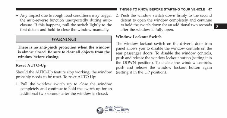
Window Lockout Switch
The window lockout switch on the driver’s door trimpanel allows you to disable the window controls on therear passenger doors. To disable the window controls,push and release the window lockout button (setting it inthe DOWN position). To enable the window controls,push and release the window lockout button again(setting it in the UP position).
2
THINGS TO KNOW BEFORE STARTING YOUR VEHICLE 47
Information Provided by:
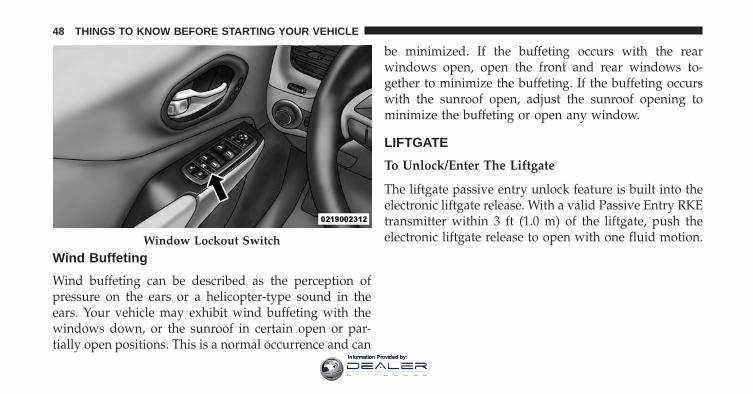
Wind Buffeting
Wind buffeting can be described as the perception ofpressure on the ears or a helicopter-type sound in theears. Your vehicle may exhibit wind buffeting with thewindows down, or the sunroof in certain open or par-tially open positions. This is a normal occurrence and can
be minimized. If the buffeting occurs with the rearwindows open, open the front and rear windows to-gether to minimize the buffeting. If the buffeting occurswith the sunroof open, adjust the sunroof opening tominimize the buffeting or open any window.
LIFTGATE
To Unlock/Enter The Liftgate
The liftgate passive entry unlock feature is built into theelectronic liftgate release. With a valid Passive Entry RKEtransmitter within 3 ft (1.0 m) of the liftgate, push theelectronic liftgate release to open with one fluid motion.Window Lockout Switch
48 THINGS TO KNOW BEFORE STARTING YOUR VEHICLE
Information Provided by:
NOTE: If “Unlock All Doors 1st Press” is programmed inEVIC/DID if equipped, all doors will unlock when youpush the electronic release on the liftgate. If �UnlockDriver Door 1st Press� is programmed in Uconnect, theliftgate will unlock when you push the electronic releaseon the liftgate. Refer to “Uconnect Settings” in “Under-standing Your Instrument Panel” for further information.
To Lock The Liftgate
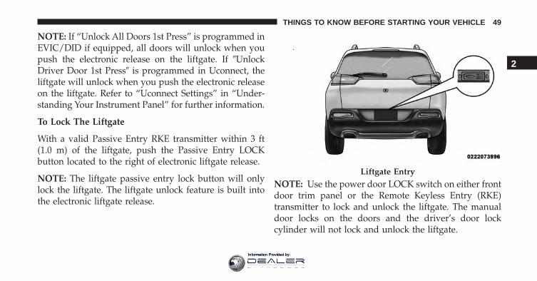
With a valid Passive Entry RKE transmitter within 3 ft(1.0 m) of the liftgate, push the Passive Entry LOCKbutton located to the right of electronic liftgate release.
NOTE: The liftgate passive entry lock button will onlylock the liftgate. The liftgate unlock feature is built intothe electronic liftgate release.
NOTE: Use the power door LOCK switch on either frontdoor trim panel or the Remote Keyless Entry (RKE)transmitter to lock and unlock the liftgate. The manualdoor locks on the doors and the driver’s door lockcylinder will not lock and unlock the liftgate.
Liftgate Entry
2
THINGS TO KNOW BEFORE STARTING YOUR VEHICLE 49
Information Provided by:
WARNING!
Driving with the liftgate open can allow poisonousexhaust gases into your vehicle. You and your pas-sengers could be injured by these fumes. Keep theliftgate closed when you are operating the vehicle.
Power Liftgate — If Equipped
The power liftgate may be opened by pushingthe electronic liftgate release (refer to “KeylessEnter-N-Go” located in “Things To Know Be-fore Starting”) or by pushing the LIFTGATE
button on the Remote Keyless Entry (RKE) transmitter.Push the LIFTGATE button on the RKE transmitter twicewithin five seconds to open the power liftgate. Once theliftgate is open, pushing the button twice within fiveseconds a second time will close the liftgate.
The power liftgate may also be opened or closed bypushing the LIFTGATE button located on the left side of
the steering wheel on the instrument panel, or closed bypushing the LIFTGATE button located on left rear trimpanel, near the liftgate opening. Push the LIFTGATEbutton located on left rear trim panel once will close theliftgate only. This button cannot be used to open theliftgate.
When the LIFTGATE button on the RKE transmitter ispushed two times, the turn signals will flash twice tosignal that the liftgate is opening or closing (if FlashLamps with Lock is enabled in the Uconnect settings),and the liftgate chime will be audible. Refer to �UconnectSettings� in �Understanding Your Instrument Panel” forfurther information.
50 THINGS TO KNOW BEFORE STARTING YOUR VEHICLE
Information Provided by:
NOTE:
• In the event of a power malfunction to the liftgate, anemergency liftgate latch release can be used to openthe liftgate. The emergency liftgate latch release can beaccessed through a snap-in cover located on the lift-gate trim panel.
• If liftgate is left open for an extended period of time,the liftgate may need to be closed manually to resetpower liftgate functionality.
WARNING!
During power operation, personal injury or cargodamage may occur. Ensure the liftgate travel path isclear. Make sure the liftgate is closed and latchedbefore driving away.
NOTE:
• The power liftgate buttons will not operate if thevehicle is in gear or the vehicle speed is above 0 mph(0 km/h).
• The power liftgate will not operate in temperaturesbelow −22°F (−30°C) or temperatures above 150°F(65°C). Be sure to remove any buildup of snow or icefrom the liftgate before pushing any of the powerliftgate switches.
• If anything obstructs the power liftgate while it isclosing or opening, the liftgate will automaticallyreverse to the closed or open position, provided itmeets sufficient resistance.
• There are also pinch sensors attached to the side of theliftgate. Light pressure anywhere along these stripswill cause the liftgate to return to the open position.
2
THINGS TO KNOW BEFORE STARTING YOUR VEHICLE 51
Information Provided by:
• The power liftgate must be in the full open position forrear liftgate close button on the left rear trim, near theliftgate opening to operate. If the liftgate is not fullyopen, push the Liftgate button on the Key Fob to fullyopen the liftgate and then push it again to close.
• If the electronic liftgate release is pushed while thepower liftgate is closing, the liftgate will reverse to thefull open position.
• If the electronic liftgate release is pushed while thepower liftgate is opening, the liftgate motor will dis-engage to allow manual operation.
• If the power liftgate encounters multiple obstructionswithin the same cycle, the system will automaticallystop and the liftgate must be opened or closed manually.
• If your liftgate is power closing and you put thevehicle in gear, the liftgate will continue to powerclose. However, vehicle movement may result in adetection of an obstruction.
WARNING!
• Driving with the liftgate open can allow poisonousexhaust gases into your vehicle. You and your pas-sengers could be injured by these fumes. Keep theliftgate closed when you are operating the vehicle.
• If you are required to drive with the liftgate open,make sure that all windows are closed, and theclimate control blower switch is set at high speed.Do not use the recirculation mode.
OCCUPANT RESTRAINT SYSTEMS
Some of the most important safety features in yourvehicle are the restraint systems:
• Seat Belt Systems
• Supplemental Restraint Systems (SRS) Air Bags
• Child Restraints
52 THINGS TO KNOW BEFORE STARTING YOUR VEHICLE
Information Provided by:
Important Safety Precautions
Please pay close attention to the information in thissection. It tells you how to use your restraint systemproperly, to keep you and your passengers as safe aspossible.
Here are some simple steps you can take to minimize therisk of harm from a deploying air bag:
1. Children 12 years old and under should always ridebuckled up in a vehicle with a rear seat.
2. If a child from 2 to 12 years old (not in a rear-facingchild restraint) must ride in the front passenger seat,move the seat as far back as possible and use theproper child restraint. (Refer to “Child Restraints”)
3. Children that are not big enough to wear the vehicleseat belt properly (Refer to �Child Restraints�) shouldbe secured in a vehicle with a rear seat in child
restraints or belt-positioning booster seats. Older chil-dren who do not use child restraints or belt-positioning booster seats should ride properly buckledup in a vehicle with a rear seat.
4. Never allow children to slide the shoulder belt behindthem or under their arm.
5. You should read the instructions provided with yourchild restraint to make sure that you are using itproperly.
6. All occupants should always wear their lap andshoulder belts properly.
7. The driver and front passenger seats should be movedback as far as practical to allow the Advanced FrontAir Bags room to inflate.
8. Do not lean against the door or window. If yourvehicle has side air bags, and deployment occurs, the
2
THINGS TO KNOW BEFORE STARTING YOUR VEHICLE 53
Information Provided by:
side air bags will inflate forcefully into the spacebetween occupants and the door and occupants couldbe injured.
9. If the air bag system in this vehicle needs to bemodified to accommodate a disabled person, contactthe Customer Center. Phone numbers are providedunder �If You Need Assistance.�
WARNING!
• Never place a rear-facing child restraint in front ofan air bag. A deploying passenger Advanced FrontAir Bag can cause death or serious injury to a child12 years or younger, including a child in a rear-facing child restraint.
• Only use a rear-facing child restraint in a vehiclewith a rear seat.
Seat Belt Systems
Buckle up even though you are an excellent driver, evenon short trips. Someone on the road may be a poor driverand could cause a collision that includes you. This canhappen far away from home or on your own street.
Research has shown that seat belts save lives, and theycan reduce the seriousness of injuries in a collision. Someof the worst injuries happen when people are thrownfrom the vehicle. Seat belts reduce the possibility ofejection and the risk of injury caused by striking theinside of the vehicle. Everyone in a motor vehicle shouldbe belted at all times.
Driver And Passenger BeltAlert (If Equipped)
BeltAlert is a feature intended to remind the driverand outboard front seat passenger (if equipped withoutboard front passenger seat BeltAlert) to buckle
54 THINGS TO KNOW BEFORE STARTING YOUR VEHICLE
Information Provided by:
their seat belts. The Belt Alert feature is active when-ever the ignition switch is in the START or ON/RUNposition.
Initial Indication
If the driver is unbuckled when the ignition switch is firstturned to the START or ON/RUN position, an intermittentchime will signal for a few seconds. If the driver oroutboard front seat passenger (if equipped with outboardfront passenger seat BeltAlert) is unbuckled when theignition switch is first turned to the START or ON/RUNposition the Seat Belt Reminder Light will turn on andremain on until both outboard front seat belts are buckled.The outboard front passenger seat BeltAlert is not activewhen an outboard front passenger seat is unoccupied.
BeltAlert Warning Sequence
The BeltAlert warning sequence is activated when thevehicle is moving above a specified vehicle speed range
and the driver or outboard front seat passenger is un-buckled (if equipped with outboard front passenger seatBeltAlert). The BeltAlert warning sequence starts byblinking the Seat Belt Reminder Light and sounding anintermittent chime. Once the BeltAlert warning sequencehas completed, the Seat Belt Reminder Light will remainon until the seat belts are buckled. The BeltAlert warningsequence may repeat based on vehicle speed until thedriver and occupied outboard front seat passenger seatbelts are buckled. The driver should instruct all occu-pants to buckle their seat belts.
Change Of Status
If the driver or outboard front seat passenger (ifequipped with outboard front passenger seat BeltAlert)unbuckles their seat belt while the vehicle is traveling,the BeltAlert warning sequence will begin until the seatbelts are buckled again.
2
THINGS TO KNOW BEFORE STARTING YOUR VEHICLE 55
Information Provided by:
The outboard front passenger seat BeltAlert is not activewhen the outboard front passenger seat is unoccupied.BeltAlert may be triggered when an animal or heavyobject is on the outboard front passenger seat or when theseat is folded flat (if equipped). It is recommended thatpets be restrained in the rear seat (if equipped) in petharnesses or pet carriers that are secured by seat belts,and cargo is properly stowed.
BeltAlert can be activated or deactivated by your autho-rized dealer. FCA US LLC does not recommend deacti-vating BeltAlert.
NOTE: If BeltAlert has been deactivated and the driveror outboard front seat passenger (if equipped with out-board front passenger seat BeltAlert) is unbuckled theSeat Belt Reminder Light will turn on and remain on untilthe driver and outboard front seat passenger seat beltsare buckled.
Lap/Shoulder Belts
All seating positions in your vehicle are equipped withlap/shoulder belts.
The seat belt webbing retractor will lock only during verysudden stops or collisions. This feature allows the shoul-der part of the seat belt to move freely with you undernormal conditions. However, in a collision the seat beltwill lock and reduce your risk of striking the inside of thevehicle or being thrown out of the vehicle.
WARNING!
• Relying on the air bags alone could lead to moresevere injuries in a collision. The air bags work withyour seat belt to restrain you properly. In somecollisions, the air bags won’t deploy at all. Alwayswear your seat belt even though you have air bags.
(Continued)
56 THINGS TO KNOW BEFORE STARTING YOUR VEHICLE
Information Provided by:
WARNING! (Continued)• In a collision, you and your passengers can suffer
much greater injuries if you are not properly buck-led up. You can strike the interior of your vehicle orother passengers, or you can be thrown out of thevehicle. Always be sure you and others in yourvehicle are buckled up properly.
• It is dangerous to ride in a cargo area, inside oroutside of a vehicle. In a collision, people riding inthese areas are more likely to be seriously injuredor killed.
• Do not allow people to ride in any area of yourvehicle that is not equipped with seats and seat belts.
• Be sure everyone in your vehicle is in a seat andusing a seat belt properly.
• Wearing your seat belt incorrectly could make yourinjuries in a collision much worse. You might
(Continued)
WARNING! (Continued)suffer internal injuries, or you could even slide outof the seat belt. Follow these instructions to wearyour seat belt safely and to keep your passengerssafe, too.
• Two people should never be belted into a singleseat belt. People belted together can crash into oneanother in a collision, hurting one another badly.Never use a lap/shoulder belt or a lap belt for morethan one person, no matter what their size.
• A lap belt worn too high can increase the risk ofinjury in a collision. The seat belt forces won’t be atthe strong hip and pelvic bones, but across yourabdomen. Always wear the lap part of your seatbelt as low as possible and keep it snug.
• A twisted seat belt may not protect you properly. Ina collision, it could even cut into you. Be sure the
(Continued)
2
THINGS TO KNOW BEFORE STARTING YOUR VEHICLE 57
Information Provided by:
WARNING! (Continued)seat belt is flat against your body, without twists. Ifyou can’t straighten a seat belt in your vehicle, takeit to your authorized dealer immediately and haveit fixed.
• A seat belt that is buckled into the wrong bucklewill not protect you properly. The lap portion couldride too high on your body, possibly causing inter-nal injuries. Always buckle your seat belt into thebuckle nearest you.
• A seat belt that is too loose will not protect youproperly. In a sudden stop, you could move too farforward, increasing the possibility of injury. Wearyour seat belt snugly.
• A seat belt that is worn under your arm is danger-ous. Your body could strike the inside surfaces ofthe vehicle in a collision, increasing head and
(Continued)
WARNING! (Continued)neck injury. A seat belt worn under the arm cancause internal injuries. Ribs aren’t as strong asshoulder bones. Wear the seat belt over yourshoulder so that your strongest bones will take theforce in a collision.
• A shoulder belt placed behind you will not protectyou from injury during a collision. You are morelikely to hit your head in a collision if you do notwear your shoulder belt. The lap and shoulder beltare meant to be used together.
• A frayed or torn seat belt could rip apart in acollision and leave you with no protection. Inspectthe seat belt system periodically, checking for cuts,frays, or loose parts. Damaged parts must be re-placed immediately. Do not disassemble or modifythe seat belt system. Seat belt assemblies must bereplaced after a collision.
58 THINGS TO KNOW BEFORE STARTING YOUR VEHICLE
Information Provided by:
Lap/Shoulder Belt Operating Instructions
1. Enter the vehicle and close the door. Sit back andadjust the seat.
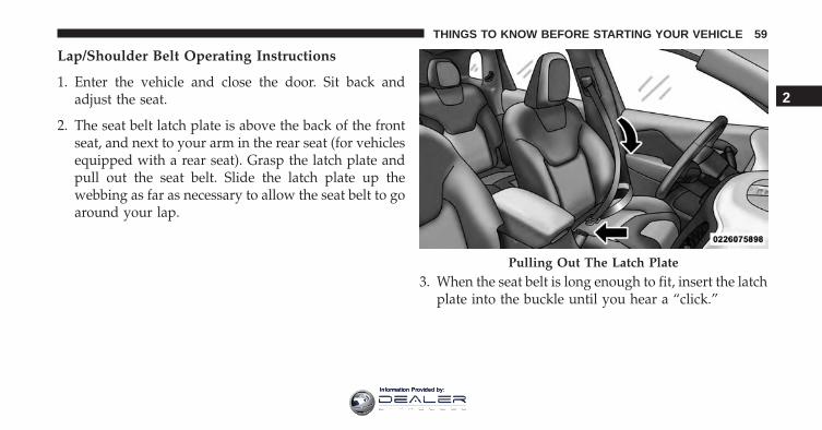
2. The seat belt latch plate is above the back of the frontseat, and next to your arm in the rear seat (for vehiclesequipped with a rear seat). Grasp the latch plate andpull out the seat belt. Slide the latch plate up thewebbing as far as necessary to allow the seat belt to goaround your lap.
3. When the seat belt is long enough to fit, insert the latchplate into the buckle until you hear a “click.”
Pulling Out The Latch Plate
2
THINGS TO KNOW BEFORE STARTING YOUR VEHICLE 59
Information Provided by:
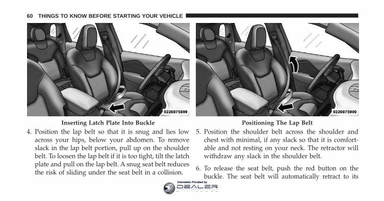
4. Position the lap belt so that it is snug and lies lowacross your hips, below your abdomen. To removeslack in the lap belt portion, pull up on the shoulderbelt. To loosen the lap belt if it is too tight, tilt the latchplate and pull on the lap belt. A snug seat belt reducesthe risk of sliding under the seat belt in a collision.
5. Position the shoulder belt across the shoulder andchest with minimal, if any slack so that it is comfort-able and not resting on your neck. The retractor willwithdraw any slack in the shoulder belt.
6. To release the seat belt, push the red button on thebuckle. The seat belt will automatically retract to its
Inserting Latch Plate Into Buckle Positioning The Lap Belt
60 THINGS TO KNOW BEFORE STARTING YOUR VEHICLE
Information Provided by:
stowed position. If necessary, slide the latch plate downthe webbing to allow the seat belt to retract fully.
Lap/Shoulder Belt Untwisting Procedure
Use the following procedure to untwist a twisted lap/shoulder belt.
1. Position the latch plate as close as possible to theanchor point.
2. At about 6 to 12 in (15 to 30 cm) above the latch plate,grasp and twist the seat belt webbing 180 degrees tocreate a fold that begins immediately above the latchplate.
3. Slide the latch plate upward over the folded webbing.The folded webbing must enter the slot at the top ofthe latch plate.
4. Continue to slide the latch plate up until it clears thefolded webbing and the seat belt is no longer twisted.
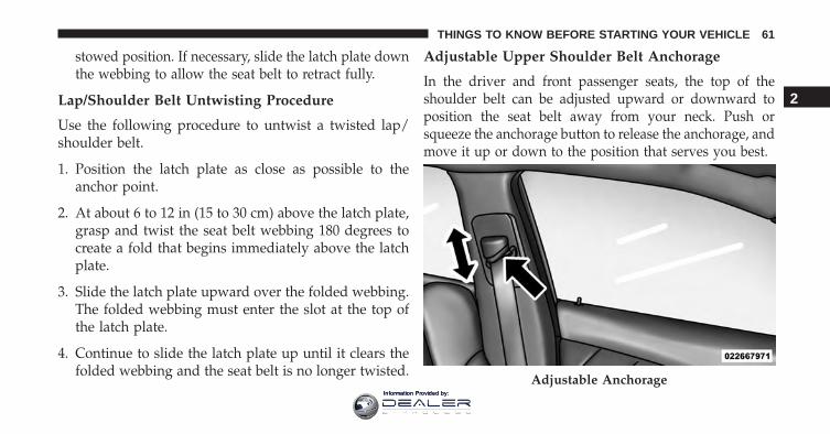
Adjustable Upper Shoulder Belt Anchorage
In the driver and front passenger seats, the top of theshoulder belt can be adjusted upward or downward toposition the seat belt away from your neck. Push orsqueeze the anchorage button to release the anchorage, andmove it up or down to the position that serves you best.
Adjustable Anchorage
2
THINGS TO KNOW BEFORE STARTING YOUR VEHICLE 61
Information Provided by:
As a guide, if you are shorter than average, you willprefer the shoulder belt anchorage in a lower position,and if you are taller than average, you will prefer theshoulder belt anchorage in a higher position. After yourelease the anchorage button, try to move it up or downto make sure that it is locked in position.
NOTE: The adjustable upper shoulder belt anchorage isequipped with an Easy Up feature. This feature allowsthe shoulder belt anchorage to be adjusted in the upwardposition without pushing or squeezing the release but-ton. To verify the shoulder belt anchorage is latched, pulldownward on the shoulder belt anchorage until it islocked into position.
Seat Belt Extender
If a seat belt is not long enough to fit properly, even whenthe webbing is fully extended and the adjustable uppershoulder belt anchorage (if equipped) is in its lowestposition, your authorized dealer can provide you with a
Seat Belt Extender. The Seat Belt Extender should be usedonly if the existing seat belt is not long enough. When theSeat Belt Extender is not required for a different occu-pant, it must be removed.
WARNING!
• ONLY use a Seat Belt Extender if it is physicallyrequired in order to properly fit the original seatbelt system. DO NOT USE the Seat Belt Extenderif, when worn, the distance between the front edgeof the Seat Belt Extender buckle and the center ofthe occupant’s body is LESS than 6 inches.
• Using a Seat Belt Extender when not needed canincrease the risk of serious injury or death in acollision. Only use the Seat Belt Extender when thelap belt is not long enough and only use in therecommended seating positions. Remove and storethe Seat Belt Extender when not needed.
62 THINGS TO KNOW BEFORE STARTING YOUR VEHICLE
Information Provided by:
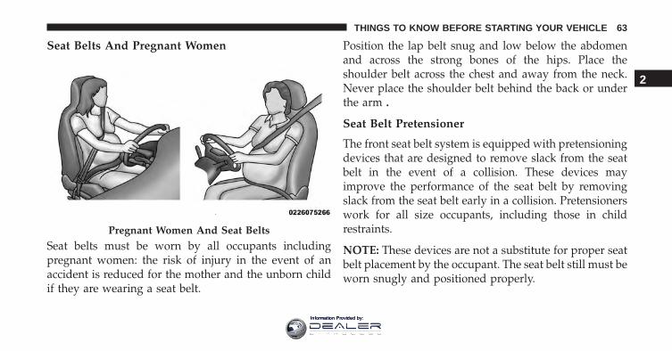
Seat Belts And Pregnant Women
Seat belts must be worn by all occupants includingpregnant women: the risk of injury in the event of anaccident is reduced for the mother and the unborn childif they are wearing a seat belt.
Position the lap belt snug and low below the abdomenand across the strong bones of the hips. Place theshoulder belt across the chest and away from the neck.Never place the shoulder belt behind the back or underthe arm .
Seat Belt Pretensioner
The front seat belt system is equipped with pretensioningdevices that are designed to remove slack from the seatbelt in the event of a collision. These devices mayimprove the performance of the seat belt by removingslack from the seat belt early in a collision. Pretensionerswork for all size occupants, including those in childrestraints.
NOTE: These devices are not a substitute for proper seatbelt placement by the occupant. The seat belt still must beworn snugly and positioned properly.
Pregnant Women And Seat Belts
2
THINGS TO KNOW BEFORE STARTING YOUR VEHICLE 63
Information Provided by:
The pretensioners are triggered by the Occupant Re-straint Controller (ORC). Like the air bags, the preten-sioners are single use items. A deployed pretensioner ora deployed air bag must be replaced immediately.
Energy Management Feature
This vehicle has a seat belt system with an EnergyManagement feature in the front seating positions thatmay help further reduce the risk of injury in the event ofa collision. This seat belt system has a retractor assemblythat is designed to release webbing in a controlledmanner.
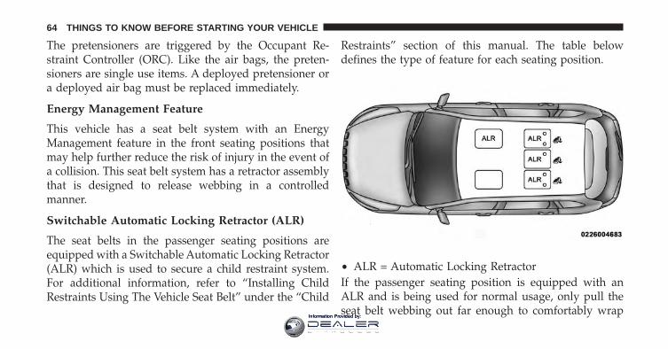
Switchable Automatic Locking Retractor (ALR)
The seat belts in the passenger seating positions areequipped with a Switchable Automatic Locking Retractor(ALR) which is used to secure a child restraint system.For additional information, refer to “Installing ChildRestraints Using The Vehicle Seat Belt” under the “Child
Restraints” section of this manual. The table belowdefines the type of feature for each seating position.
If the passenger seating position is equipped with anALR and is being used for normal usage, only pull theseat belt webbing out far enough to comfortably wrap
• ALR = Automatic Locking Retractor
64 THINGS TO KNOW BEFORE STARTING YOUR VEHICLE
Information Provided by:
around the occupant’s mid-section so as to not activatethe ALR. If the ALR is activated, you will hear a clickingsound as the seat belt retracts. Allow the webbing toretract completely in this case and then carefully pull outonly the amount of webbing necessary to comfortablywrap around the occupant’s mid-section. Slide the latchplate into the buckle until you hear a �click.�
In Automatic Locking Mode, the shoulder belt is auto-matically pre-locked. The seat belt will still retract toremove any slack in the shoulder belt. Use the AutomaticLocking Mode anytime a child restraint is installed in aseating position that has a seat belt with this feature.Children 12 years old and under should always beproperly restrained in a vehicle with a rear seat.
WARNING!
• Never place a rear-facing child restraint in front ofan air bag. A deploying Passenger Advanced FrontAir Bag can cause death or serious injury to a child12 years or younger, including a child in a rear-facing child restraint.
• Only use a rear-facing child restraint in a vehiclewith a rear seat.
How To Engage The Automatic Locking Mode
1. Buckle the combination lap and shoulder belt.
2. Grasp the shoulder portion and pull downward untilthe entire seat belt is extracted.
3. Allow the seat belt to retract. As the seat belt retracts,you will hear a clicking sound. This indicates the seatbelt is now in the Automatic Locking Mode.
2
THINGS TO KNOW BEFORE STARTING YOUR VEHICLE 65
Information Provided by:
How To Disengage The Automatic Locking Mode
Unbuckle the combination lap/shoulder belt and allow itto retract completely to disengage the Automatic LockingMode and activate the vehicle sensitive (emergency)locking mode.
WARNING!
• The seat belt assembly must be replaced if theswitchable Automatic Locking Retractor (ALR) fea-ture or any other seat belt function is not workingproperly when checked according to the proce-dures in the Service Manual.
• Failure to replace the seat belt assembly couldincrease the risk of injury in collisions.
• Do not use the Automatic Locking Mode to restrainoccupants who are wearing the seat belt or childrenwho are using booster seats. The locked mode is
(Continued)
WARNING! (Continued)only used to install rear-facing or forward-facingchild restraints that have a harness for restrainingthe child.
Supplemental Restraint System (SRS)
Air Bag System Components
Your vehicle may be equipped with the following air bagsystem components:• Occupant Restraint Controller (ORC)
• Air Bag Warning Light
• Steering Wheel and Column
• Instrument Panel
• Knee Impact Bolsters
• Advanced Front Air Bags
• Supplemental Side Air Bags
66 THINGS TO KNOW BEFORE STARTING YOUR VEHICLE
Information Provided by:
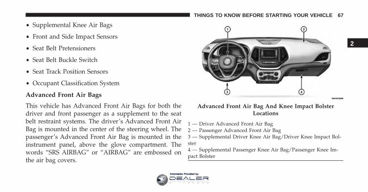
• Supplemental Knee Air Bags
• Front and Side Impact Sensors
• Seat Belt Pretensioners
• Seat Belt Buckle Switch
• Seat Track Position Sensors
• Occupant Classification System
Advanced Front Air Bags
This vehicle has Advanced Front Air Bags for both thedriver and front passenger as a supplement to the seatbelt restraint systems. The driver’s Advanced Front AirBag is mounted in the center of the steering wheel. Thepassenger’s Advanced Front Air Bag is mounted in theinstrument panel, above the glove compartment. Thewords “SRS AIRBAG” or “AIRBAG” are embossed onthe air bag covers.
Advanced Front Air Bag And Knee Impact BolsterLocations
1 — Driver Advanced Front Air Bag2 — Passenger Advanced Front Air Bag3 — Supplemental Driver Knee Air Bag/Driver Knee Impact Bol-ster4 — Supplemental Passenger Knee Air Bag/Passenger Knee Im-pact Bolster
2
THINGS TO KNOW BEFORE STARTING YOUR VEHICLE 67
Information Provided by:
WARNING!
• Being too close to the steering wheel or instrumentpanel during Advanced Front Air Bag deploymentcould cause serious injury, including death. Airbags need room to inflate. Sit back, comfortablyextending your arms to reach the steering wheel orinstrument panel.
• Never place a rear-facing child restraint in front ofan air bag. A deploying Passenger Advanced FrontAir Bag can cause death or serious injury to a child12 years or younger, including a child in a rear-facing child restraint.
• Only use a rear-facing child restraint in a vehiclewith a rear seat.
Advanced Front Air Bag Features
The Advanced Front Air Bag system has multistagedriver and front passenger air bags. This system provides
output appropriate to the severity and type of collision asdetermined by the Occupant Restraint Controller (ORC),which may receive information from the front impactsensors or other system components.
The first stage inflator is triggered immediately during animpact that requires air bag deployment. A low energyoutput is used in less severe collisions. A higher energyoutput is used for more severe collisions.
This vehicle may be equipped with driver and/or frontpassenger seat track position sensors that may adjust theinflation rate of the Advanced Front Air Bags based uponseat position.
This vehicle may be equipped with a driver and/or frontpassenger seat belt buckle switch that detects whetherthe driver or front passenger seat belt is buckled. The seatbelt buckle switch may adjust the inflation rate of theAdvanced Front Air Bags.
68 THINGS TO KNOW BEFORE STARTING YOUR VEHICLE
Information Provided by:
WARNING!
• No objects should be placed over or near the airbag on the instrument panel or steering wheel,because any such objects could cause harm if thevehicle is in a collision severe enough to cause theair bags to inflate.
• Do not put anything on or around the air bagcovers or attempt to open them manually. You maydamage the air bags and you could be injuredbecause the air bags may no longer be functional.The protective covers for the air bag cushions aredesigned to open only when the air bags areinflating.
• Relying on the air bags alone could lead to moresevere injuries in a collision. The air bags work withyour seat belt to restrain you properly. In somecollisions, air bags won’t deploy at all. Always wearyour seat belts even though you have air bags.
Advanced Front Air Bag Operation
Advanced Front Air Bags are designed to provide addi-tional protection by supplementing the seat belts. Ad-vanced Front Air Bags are not expected to reduce the riskof injury in rear, side, or rollover collisions. The Ad-vanced Front Air Bags will not deploy in all frontalcollisions, including some that may produce substantialvehicle damage — for example, some pole collisions,truck underrides, and angle offset collisions.
On the other hand, depending on the type and location ofimpact, Advanced Front Air Bags may deploy in crasheswith little vehicle front-end damage but that produce asevere initial deceleration.
Because air bag sensors measure vehicle decelerationover time, vehicle speed and damage by themselves arenot good indicators of whether or not an air bag shouldhave deployed.
2
THINGS TO KNOW BEFORE STARTING YOUR VEHICLE 69
Information Provided by:
Seat belts are necessary for your protection in all colli-sions, and also are needed to help keep you in position,away from an inflating air bag.
When the ORC detects a collision requiring the Ad-vanced Front Air Bags, it signals the inflator units. A largequantity of non-toxic gas is generated to inflate theAdvanced Front Air Bags.
The steering wheel hub trim cover and the upper rightside of the instrument panel separate and fold out of theway as the air bags inflate to their full size. The AdvancedFront Air Bags fully inflate in less time than it takes toblink your eyes. The air bags then quickly deflate whilehelping to restrain the driver and front passenger.
Occupant Classification System (OCS) — FrontPassenger Seat
The OCS is part of a Federally regulated safety system forthis vehicle. It is designed to provide Passenger Ad-vanced Front Air Bag output appropriate to the occu-pant’s seated weight, as determined by the OCS.
The Occupant Classification System (OCS) consists of thefollowing:
• Occupant Restraint Controller (ORC)
• Occupant Classification Module (OCM) and Sensorlocated in the front passenger seat
• Air Bag Warning Light
Occupant Classification Module (OCM) and Sensor
The Occupant Classification Module (OCM) is locatedunderneath the front passenger seat. The Sensor is lo-cated beneath the passenger seat cushion foam. Any
70 THINGS TO KNOW BEFORE STARTING YOUR VEHICLE
Information Provided by:
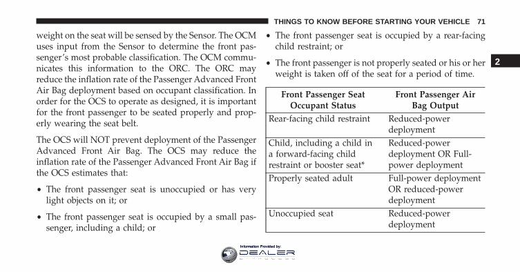
weight on the seat will be sensed by the Sensor. The OCMuses input from the Sensor to determine the front pas-senger’s most probable classification. The OCM commu-nicates this information to the ORC. The ORC mayreduce the inflation rate of the Passenger Advanced FrontAir Bag deployment based on occupant classification. Inorder for the OCS to operate as designed, it is importantfor the front passenger to be seated properly and prop-erly wearing the seat belt.
The OCS will NOT prevent deployment of the PassengerAdvanced Front Air Bag. The OCS may reduce theinflation rate of the Passenger Advanced Front Air Bag ifthe OCS estimates that:
• The front passenger seat is unoccupied or has verylight objects on it; or
• The front passenger seat is occupied by a small pas-senger, including a child; or
• The front passenger seat is occupied by a rear-facingchild restraint; or
• The front passenger is not properly seated or his or herweight is taken off of the seat for a period of time.
Front Passenger SeatOccupant Status
Front Passenger AirBag Output
Rear-facing child restraint Reduced-powerdeployment
Child, including a child ina forward-facing childrestraint or booster seat*
Reduced-powerdeployment OR Full-power deployment
Properly seated adult Full-power deploymentOR reduced-powerdeployment
Unoccupied seat Reduced-powerdeployment
2
THINGS TO KNOW BEFORE STARTING YOUR VEHICLE 71
Information Provided by:
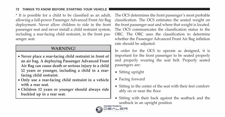
* It is possible for a child to be classified as an adult,allowing a full-power Passenger Advanced Front Air Bagdeployment. Never allow children to ride in the frontpassenger seat and never install a child restraint system,including a rear-facing child restraint, in the front pas-senger seat.
WARNING!
• Never place a rear-facing child restraint in front ofan air bag. A deploying Passenger Advanced FrontAir Bag can cause death or serious injury to a child12 years or younger, including a child in a rear-facing child restraint.
• Only use a rear-facing child restraint in a vehiclewith a rear seat.
• Children 12 years or younger should always ridebuckled up in a rear seat.
The OCS determines the front passenger’s most probableclassification. The OCS estimates the seated weight onthe front passenger seat and where that weight is located.The OCS communicates the classification status to theORC. The ORC uses the classification to determinewhether the Passenger Advanced Front Air Bag inflationrate should be adjusted.
In order for the OCS to operate as designed, it isimportant for the front passenger to be seated properlyand properly wearing the seat belt. Properly seatedpassengers are:
• Sitting upright
• Facing forward
• Sitting in the center of the seat with their feet comfort-ably on or near the floor
• Sitting with their back against the seatback and theseatback in an upright position
72 THINGS TO KNOW BEFORE STARTING YOUR VEHICLE
Information Provided by:
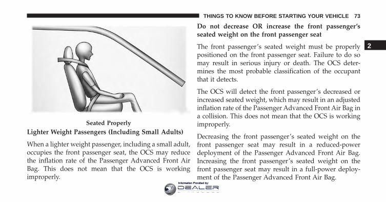
Lighter Weight Passengers (Including Small Adults)
When a lighter weight passenger, including a small adult,occupies the front passenger seat, the OCS may reducethe inflation rate of the Passenger Advanced Front AirBag. This does not mean that the OCS is workingimproperly.
Do not decrease OR increase the front passenger’sseated weight on the front passenger seat
The front passenger’s seated weight must be properlypositioned on the front passenger seat. Failure to do somay result in serious injury or death. The OCS deter-mines the most probable classification of the occupantthat it detects.
The OCS will detect the front passenger’s decreased orincreased seated weight, which may result in an adjustedinflation rate of the Passenger Advanced Front Air Bag ina collision. This does not mean that the OCS is workingimproperly.
Decreasing the front passenger’s seated weight on thefront passenger seat may result in a reduced-powerdeployment of the Passenger Advanced Front Air Bag.Increasing the front passenger’s seated weight on thefront passenger seat may result in a full-power deploy-ment of the Passenger Advanced Front Air Bag.
Seated Properly
2
THINGS TO KNOW BEFORE STARTING YOUR VEHICLE 73
Information Provided by:
Examples of improper front passenger seating include:
• The front passenger’s weight is transferred to anotherpart of the vehicle (like the door, arm rest or instru-ment panel).
• The front passenger leans forward, sideways, or turnsto face the rear of the vehicle.
• The front passenger’s seatback is not in the full uprightposition.
• The front passenger carries or holds an object whileseated (e.g., backpack, box, etc.).
• Objects are lodged under the front passenger seat.
• Objects are lodged between the front passenger seatand center console.
• Accessories that may change the seated weight on thefront passenger seat are attached to the front passengerseat.
• Anything that may decrease or increase the frontpassenger’s seated weight.
The OCS determines the front passenger’s most probableclassification. If an occupant in the front passenger seat isseated improperly, the occupant may provide an outputsignal to the OCS that is different from the occupant’sproperly seated weight input, for example:
74 THINGS TO KNOW BEFORE STARTING YOUR VEHICLE
Information Provided by:
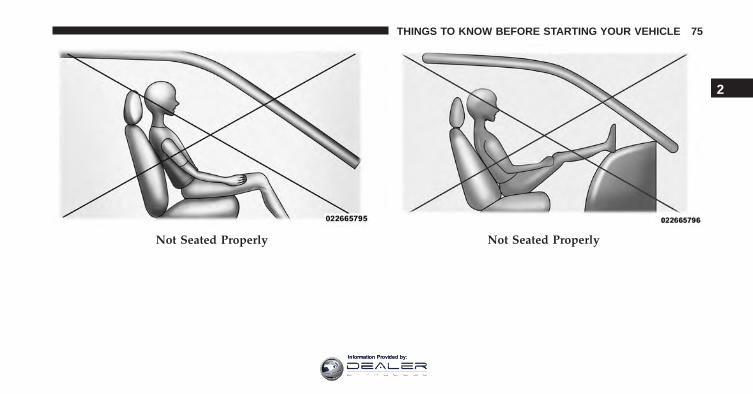
Not Seated Properly Not Seated Properly
2
THINGS TO KNOW BEFORE STARTING YOUR VEHICLE 75
Information Provided by:
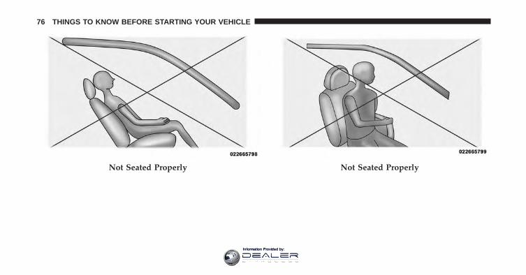
Not Seated Properly Not Seated Properly
76 THINGS TO KNOW BEFORE STARTING YOUR VEHICLE
Information Provided by:
WARNING!
• If an occupant in the front passenger seat is seatedimproperly, the occupant may provide an outputsignal to the OCS that is different from the occu-pant’s properly seated weight input. This mayresult in serious injury or death in a collision.
• Always wear your seat belt and sit properly, withthe seatback in an upright position, your backagainst the seatback, sitting upright, facing for-ward, in the center of the seat, with your feetcomfortably on or near the floor.
• Do not carry or hold any objects (e.g., backpacks,boxes, etc.) while seated in the front passenger seat.Holding an object may provide an output signal tothe OCS that is different than the occupant’s prop-erly seated weight input, which may result inserious injury or death in a collision.
(Continued)
WARNING! (Continued)• Placing an object on the floor under the front
passenger seat may prevent the OCS from workingproperly, which may result in serious injury ordeath in a collision. Do not place any objects on thefloor under the front passenger seat.
The Air Bag Warning Light in the instrument panelwill turn on whenever the OCS is unable to classify thefront passenger seat status. A malfunction in the OCSmay affect the operation of the air bag system.
If the Air Bag Warning Light does not come on, orstays on after you start the vehicle, or it comes on asyou drive, take the vehicle to an authorized dealer forservice immediately.
The passenger seat assembly contains critical OCS com-ponents that may affect the Passenger Advanced FrontAir Bag inflation. In order for the OCS to properly
2
THINGS TO KNOW BEFORE STARTING YOUR VEHICLE 77
Information Provided by:
classify the seated weight of a front seat passenger, theOCS components must function as designed.
Do not make any modifications to the front passengerseat components, assembly, or to the seat cover. If theseat, trim cover, or cushion needs service for any reason,take the vehicle to your authorized dealer. Only FCA LLCapproved seat accessories may be used.
The following requirements must be strictly followed:
• Do not modify the front passenger seat assembly orcomponents in any way.
• Do not use prior or future model year seat covers orcushions not designated by FCA US LLC for thespecific model being repaired. Always use the correctseat cover and cushion specified for the vehicle.
• Do not replace the seat cover or cushion with anaftermarket seat cover or cushion.
• Do not add a secondary seat cover or mat.
• At no time should any Supplemental Restraint System(SRS) component or SRS related component or fastenerbe modified or replaced with any part except thosewhich are approved by FCA US LLC.
WARNING!
Unapproved modifications or service procedures tothe passenger seat assembly, its related components,seat cover or cushion may inadvertently change theair bag deployment in case of a frontal collision. Thiscould result in death or serious injury to the frontpassenger if the vehicle is involved in a collision. Amodified vehicle may not comply with requiredFederal Motor Vehicle Safety Standards (FMVSS)and/or Canadian Motor Vehicle Safety Standards(CMVSS).
78 THINGS TO KNOW BEFORE STARTING YOUR VEHICLE
Information Provided by:
Knee Impact Bolsters
The Knee Impact Bolsters help protect the knees of thedriver and front passenger, and position the front occu-pants for improved interaction with the Advanced FrontAir Bags.
WARNING!
• Do not drill, cut, or tamper with the knee impactbolsters in any way.
• Do not mount any accessories to the knee impactbolsters such as alarm lights, stereos, citizen bandradios, etc.
Supplemental Driver And Front Passenger KneeAir Bags
This vehicle is equipped with a Supplemental DriverKnee Air Bag mounted in the instrument panel below thesteering column and a Supplemental Passenger Knee Air
Bag mounted in the instrument panel below the glovecompartment. The Supplemental Knee Air Bags provideenhanced protection during a frontal impact by workingtogether with the seat belts, pretensioners, and AdvancedFront Air Bags.
Supplemental Side Air Bags
Your vehicle is equipped with two types of side air bags:
1. Supplemental Seat-Mounted Side Air Bags (SABs):Located in the outboard side of the front and rear (invehicles equipped with rear seat SABs) seats. TheSABs are marked with a “SRS AIRBAG” or “AIRBAG”label sewn into the outboard side of the seats.
2
THINGS TO KNOW BEFORE STARTING YOUR VEHICLE 79
Information Provided by:
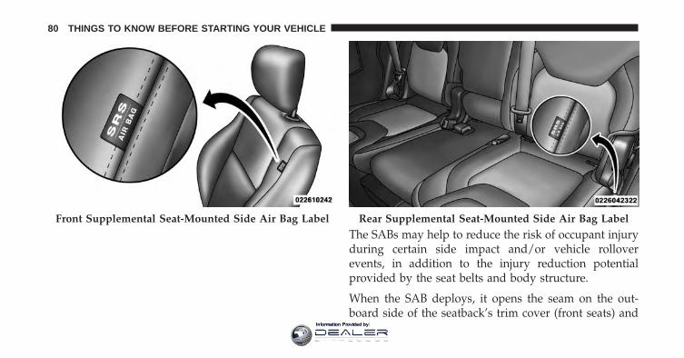
The SABs may help to reduce the risk of occupant injuryduring certain side impact and/or vehicle rolloverevents, in addition to the injury reduction potentialprovided by the seat belts and body structure.
When the SAB deploys, it opens the seam on the out-board side of the seatback’s trim cover (front seats) and
Front Supplemental Seat-Mounted Side Air Bag Label Rear Supplemental Seat-Mounted Side Air Bag Label
80 THINGS TO KNOW BEFORE STARTING YOUR VEHICLE
Information Provided by:
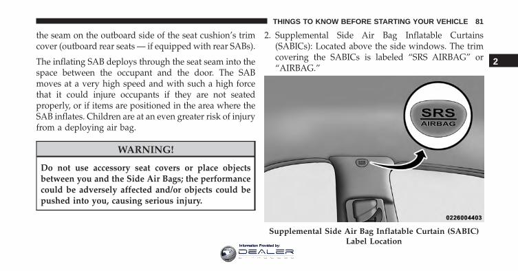
the seam on the outboard side of the seat cushion’s trimcover (outboard rear seats — if equipped with rear SABs).
The inflating SAB deploys through the seat seam into thespace between the occupant and the door. The SABmoves at a very high speed and with such a high forcethat it could injure occupants if they are not seatedproperly, or if items are positioned in the area where theSAB inflates. Children are at an even greater risk of injuryfrom a deploying air bag.
WARNING!
Do not use accessory seat covers or place objectsbetween you and the Side Air Bags; the performancecould be adversely affected and/or objects could bepushed into you, causing serious injury.
2. Supplemental Side Air Bag Inflatable Curtains(SABICs): Located above the side windows. The trimcovering the SABICs is labeled “SRS AIRBAG” or“AIRBAG.”
Supplemental Side Air Bag Inflatable Curtain (SABIC)Label Location
2
THINGS TO KNOW BEFORE STARTING YOUR VEHICLE 81
Information Provided by:
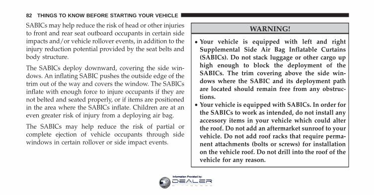
SABICs may help reduce the risk of head or other injuriesto front and rear seat outboard occupants in certain sideimpacts and/or vehicle rollover events, in addition to theinjury reduction potential provided by the seat belts andbody structure.
The SABICs deploy downward, covering the side win-dows. An inflating SABIC pushes the outside edge of thetrim out of the way and covers the window. The SABICsinflate with enough force to injure occupants if they arenot belted and seated properly, or if items are positionedin the area where the SABICs inflate. Children are at aneven greater risk of injury from a deploying air bag.
The SABICs may help reduce the risk of partial orcomplete ejection of vehicle occupants through sidewindows in certain rollover or side impact events.
WARNING!
• Your vehicle is equipped with left and rightSupplemental Side Air Bag Inflatable Curtains(SABICs). Do not stack luggage or other cargo uphigh enough to block the deployment of theSABICs. The trim covering above the side win-dows where the SABIC and its deployment pathare located should remain free from any obstruc-tions.
• Your vehicle is equipped with SABICs. In order forthe SABICs to work as intended, do not install anyaccessory items in your vehicle which could alterthe roof. Do not add an aftermarket sunroof to yourvehicle. Do not add roof racks that require perma-nent attachments (bolts or screws) for installationon the vehicle roof. Do not drill into the roof of thevehicle for any reason.
82 THINGS TO KNOW BEFORE STARTING YOUR VEHICLE
Information Provided by:
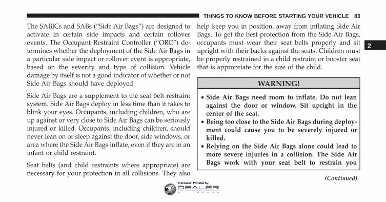
The SABICs and SABs (“Side Air Bags”) are designed toactivate in certain side impacts and certain rolloverevents. The Occupant Restraint Controller (“ORC”) de-termines whether the deployment of the Side Air Bags ina particular side impact or rollover event is appropriate,based on the severity and type of collision. Vehicledamage by itself is not a good indicator of whether or notSide Air Bags should have deployed.
Side Air Bags are a supplement to the seat belt restraintsystem. Side Air Bags deploy in less time than it takes toblink your eyes. Occupants, including children, who areup against or very close to Side Air Bags can be seriouslyinjured or killed. Occupants, including children, shouldnever lean on or sleep against the door, side windows, orarea where the Side Air Bags inflate, even if they are in aninfant or child restraint.
Seat belts (and child restraints where appropriate) arenecessary for your protection in all collisions. They also
help keep you in position, away from inflating Side AirBags. To get the best protection from the Side Air Bags,occupants must wear their seat belts properly and situpright with their backs against the seats. Children mustbe properly restrained in a child restraint or booster seatthat is appropriate for the size of the child.
WARNING!
• Side Air Bags need room to inflate. Do not leanagainst the door or window. Sit upright in thecenter of the seat.
• Being too close to the Side Air Bags during deploy-ment could cause you to be severely injured orkilled.
• Relying on the Side Air Bags alone could lead tomore severe injuries in a collision. The Side AirBags work with your seat belt to restrain you
(Continued)
2
THINGS TO KNOW BEFORE STARTING YOUR VEHICLE 83
Information Provided by:
WARNING! (Continued)properly. In some collisions, Side Air Bags won’tdeploy at all. Always wear your seat belt eventhough you have Side Air Bags.
NOTE: Air bag covers may not be obvious in the interiortrim, but they will open during air bag deployment.
Side Impacts
In side impacts, the side impact sensors aid the ORC indetermining the appropriate response to impact events.The system is calibrated to deploy the Side Air Bags onthe impact side of the vehicle during impacts that requireSide Air Bag occupant protection. In side impacts, theSide Air Bags deploy independently; a left side impactdeploys the left Side Air Bags only and a right sideimpact deploys the right Side Air Bags only.
The Side Air Bags will not deploy in all side collisions,including some collisions at certain angles, or some sidecollisions that do not impact the area of the passengercompartment. The Side Air Bags may deploy duringangled or offset frontal collisions where the AdvancedFront Air Bags deploy.
Rollover Events
Side Air Bags are designed to activate in certain rolloverevents. The ORC determines whether the deployment ofthe Side Air Bags in a particular rollover event is appro-priate, based on the severity and type of collision. Vehicledamage by itself is not a good indicator of whether or notSide Air Bags should have deployed.
The Side Air Bags will not deploy in all rollover events.The rollover sensing-system determines if a rolloverevent may be in progress and whether deployment isappropriate. A slower-developing event may deploy theseat belt pretensioners on both sides of the vehicle. A
84 THINGS TO KNOW BEFORE STARTING YOUR VEHICLE
Information Provided by:
faster-developing event may deploy the seat belt preten-sioners as well as the Side Air Bags on both sides of thevehicle. The rollover sensing-system may also deploy theseat belt pretensioners, with or without the Side Air Bags,on both sides of the vehicle if the vehicle experiences anear rollover event.
If A Deployment Occurs
The Advanced Front Air Bags are designed to deflateimmediately after deployment.
NOTE: Front and/or side air bags will not deploy in allcollisions. This does not mean something is wrong withthe air bag system.
If you do have a collision which deploys the air bags, anyor all of the following may occur:
• The air bag material may sometimes cause abrasionsand/or skin reddening to the occupants as the air bags
deploy and unfold. The abrasions are similar to fric-tion rope burns or those you might get sliding along acarpet or gymnasium floor. They are not caused bycontact with chemicals. They are not permanent andnormally heal quickly. However, if you haven’t healedsignificantly within a few days, or if you have anyblistering, see your doctor immediately.
• As the air bags deflate, you may see some smoke-likeparticles. The particles are a normal by-product of theprocess that generates the non-toxic gas used for airbag inflation. These airborne particles may irritate theskin, eyes, nose, or throat. If you have skin or eyeirritation, rinse the area with cool water. For nose orthroat irritation, move to fresh air. If the irritationcontinues, see your doctor. If these particles settle onyour clothing, follow the garment manufacturer’s in-structions for cleaning.
2
THINGS TO KNOW BEFORE STARTING YOUR VEHICLE 85
Information Provided by:
Do not drive your vehicle after the air bags have de-ployed. If you are involved in another collision, the airbags will not be in place to protect you.
WARNING!
Deployed air bags and seat belt pretensioners cannotprotect you in another collision. Have the air bags,seat belt pretensioners, and the seat belt retractorassemblies replaced by an authorized dealer imme-diately. Also, have the Occupant Restraint ControllerSystem serviced as well.
NOTE:
• Air bag covers may not be obvious in the interior trim,but they will open during air bag deployment.
• After any collision, the vehicle should be taken to anauthorized dealer immediately.
Enhanced Accident Response System
In the event of an impact, if the communication networkremains intact, and the power remains intact, dependingon the nature of the event, the ORC will determinewhether to have the Enhanced Accident Response Sys-tem perform the following functions:
• Cut off fuel to the engine.
• Flash hazard lights as long as the battery has power oruntil the hazard light button is pressed. The hazardlights can be deactivated by pressing the hazard lightbutton.
• Turn on the interior lights, which remain on as long asthe battery has power.
• Unlock the power door locks.
86 THINGS TO KNOW BEFORE STARTING YOUR VEHICLE
Information Provided by:
Enhanced Accident Response System ResetProcedure
In order to reset the Enhanced Accident Response Systemfunctions after an event, the ignition switch must bechanged from ignition START or ON/RUN to ignitionOFF. Carefully check the vehicle for fuel leaks in theengine compartment and on the ground near the enginecompartment and fuel tank before resetting the systemand starting the engine.
Air Bag Warning Light
The air bags must be ready to inflate for yourprotection in a collision. The Occupant Re-straint Controller (ORC) monitors the internalcircuits and interconnecting wiring associated
with air bag system electrical components.
The ORC monitors the readiness of the electronic parts ofthe air bag system whenever the ignition switch is in theSTART or ON/RUN position. If the ignition switch is in
the OFF position or in the ACC position, the air bagsystem is not on and the air bags will not inflate.
The ORC contains a backup power supply system thatmay deploy the air bags even if the battery loses power orit becomes disconnected prior to deployment.
The ORC turns on the Air Bag Warning Light in theinstrument panel for approximately four to eight secondsfor a self-check when the ignition switch is first turned tothe ON/RUN position. After the self-check, the Air BagWarning Light will turn off. If the ORC detects a mal-function in any part of the system, it turns on the Air BagWarning Light, either momentarily or continuously. Asingle chime will sound to alert you if the light comes onagain after initial startup.
The ORC also includes diagnostics that will illuminatethe instrument panel Air Bag Warning Light if a malfunc-tion is detected that could affect the air bag system. Thediagnostics also record the nature of the malfunction.
2
THINGS TO KNOW BEFORE STARTING YOUR VEHICLE 87
Information Provided by:
While the air bag system is designed to be maintenancefree, if any of the following occurs, have an authorizeddealer service the air bag system immediately.
• The Air Bag Warning Light does not come on duringthe four to eight seconds when the ignition switch isfirst turned to the ON/RUN position.
• The Air Bag Warning Light remains on after the four toeight-second interval.
• The Air Bag Warning Light comes on intermittently orremains on while driving.
NOTE: If the speedometer, tachometer, or any enginerelated gauges are not working, the Occupant RestraintController (ORC) may also be disabled. In this conditionthe air bags may not be ready to inflate for your protec-tion. Have an authorized dealer service the air bagsystem immediately.
WARNING!
Ignoring the Air Bag Warning Light in your instrumentpanel could mean you won’t have the air bags toprotect you in a collision. If the light does not come onas a bulb check when the ignition is first placed in theon position, and stays on after you start the vehicle, orif it comes on as you drive, have an authorized dealerservice the air bag system immediately.
88 THINGS TO KNOW BEFORE STARTING YOUR VEHICLE
Information Provided by:
Redundant Air Bag Warning Light
If a fault with the Air Bag Warning Light isdetected, which could affect the SupplementalRestraint System (“SRS”), the Redundant AirBag Warning Light will illuminate on the in-
strument panel. The Redundant Air Bag Warning Lightwill stay on until the fault is cleared. In addition, a singlechime will sound to alert you that the Redundant Air BagWarning Light has come on and a fault has been detected.If the Redundant Air Bag Warning Light comes onintermittently or remains on while driving have anauthorized dealer service the vehicle immediately. Foradditional information regarding the Redundant Air BagWarning Light refer to the “Instrument Panel” section ofthis manual.
Maintaining Your Air Bag System
WARNING!
• Modifications to any part of the air bag systemcould cause it to fail when you need it. You couldbe injured if the air bag system is not there toprotect you. Do not modify the components orwiring, including adding any kind of badges orstickers to the steering wheel hub trim cover or theupper right side of the instrument panel. Do notmodify the front bumper, vehicle body structure, oradd aftermarket side steps or running boards.
• It is dangerous to try to repair any part of the airbag system yourself. Be sure to tell anyone whoworks on your vehicle that it has an air bag system.
• Do not attempt to modify any part of your air bagsystem. The air bag may inflate accidentally or may
(Continued)
2
THINGS TO KNOW BEFORE STARTING YOUR VEHICLE 89
Information Provided by:
WARNING! (Continued)not function properly if modifications are made.Take your vehicle to an authorized dealer for anyair bag system service. If your seat, including yourtrim cover and cushion, needs to be serviced in anyway (including removal or loosening/tightening ofseat attachment bolts), take the vehicle to yourauthorized dealer. Only manufacturer approvedseat accessories may be used. If it is necessary tomodify the air bag system for persons with dis-abilities, contact your authorized dealer.
Event Data Recorder (EDR)
This vehicle is equipped with an event data recorder(EDR). The main purpose of an EDR is to record, incertain crash or near crash-like situations, such as an airbag deployment or hitting a road obstacle, data that will
assist in understanding how a vehicle’s systems per-formed. The EDR is designed to record data related tovehicle dynamics and safety systems for a short period oftime, typically 30 seconds or less. The EDR in this vehicleis designed to record such data as:
• How various systems in your vehicle were operating;
• Whether or not the driver and passenger safety beltswere buckled/fastened;
• How far (if at all) the driver was depressing theaccelerator and/or brake pedal; and,
• How fast the vehicle was traveling.
These data can help provide a better understanding ofthe circumstances in which crashes and injuries occur.
90 THINGS TO KNOW BEFORE STARTING YOUR VEHICLE
Information Provided by:
NOTE: EDR data are recorded by your vehicle only if anon-trivial crash situation occurs; no data are recorded bythe EDR under normal driving conditions and no per-sonal data (e.g., name, gender, age, and crash location)are recorded. However, other parties, such as law en-forcement, could combine the EDR data with the type ofpersonally identifying data routinely acquired during acrash investigation.
To read data recorded by an EDR, special equipment isrequired, and access to the vehicle or the EDR is needed.In addition to the vehicle manufacturer, other parties,such as law enforcement, that have the special equip-ment, can read the information if they have access to thevehicle or the EDR.
Child Restraints
Everyone in your vehicle needs to be buckled up at alltimes, including babies and children.
Every state in the United States, and every Canadianprovince, requires that small children ride in properrestraint systems. This is the law, and you can be pros-ecuted for ignoring it.
Children 12 years or younger should ride properlybuckled up in a rear seat, if available. According to crashstatistics, children are safer when properly restrained inthe rear seats rather than in the front.
WARNING!
In a collision, an unrestrained child can become aprojectile inside the vehicle. The force required tohold even an infant on your lap could become sogreat that you could not hold the child, no matterhow strong you are. The child and others could bebadly injured. Any child riding in your vehicleshould be in a proper restraint for the child’s size.
2
THINGS TO KNOW BEFORE STARTING YOUR VEHICLE 91
Information Provided by:
There are different sizes and types of restraints forchildren from newborn size to the child almost largeenough for an adult safety belt. Always check the childseat Owner’s Manual to make sure you have the correctseat for your child. Carefully read and follow all theinstructions and warnings in the child restraint Owner’sManual and on all the labels attached to the childrestraint.
Before buying any restraint system, make sure that it hasa label certifying that it meets all applicable SafetyStandards. You should also make sure that you can installit in the vehicle where you will use it.
NOTE:
• For additional information, refer to www.seatcheck.orgor call 1–866–732–8243.
• Canadian residents should refer to Transport Canada’swebsite for additional information: www.tc.gc.ca/eng/motorvehiclesafety/safedrivers-childsafety-index-53.htm
92 THINGS TO KNOW BEFORE STARTING YOUR VEHICLE
Information Provided by:
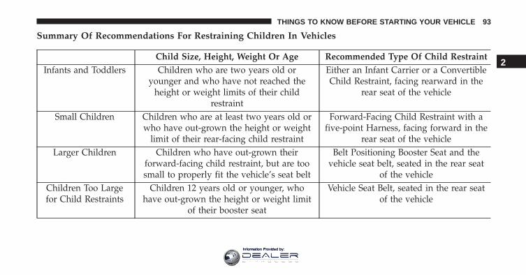
Summary Of Recommendations For Restraining Children In Vehicles
Child Size, Height, Weight Or Age Recommended Type Of Child RestraintInfants and Toddlers Children who are two years old or
younger and who have not reached theheight or weight limits of their child
restraint
Either an Infant Carrier or a ConvertibleChild Restraint, facing rearward in the
rear seat of the vehicle
Small Children Children who are at least two years old orwho have out-grown the height or weight
limit of their rear-facing child restraint
Forward-Facing Child Restraint with afive-point Harness, facing forward in the
rear seat of the vehicleLarger Children Children who have out-grown their
forward-facing child restraint, but are toosmall to properly fit the vehicle’s seat belt
Belt Positioning Booster Seat and thevehicle seat belt, seated in the rear seat
of the vehicleChildren Too Largefor Child Restraints
Children 12 years old or younger, whohave out-grown the height or weight limit
of their booster seat
Vehicle Seat Belt, seated in the rear seatof the vehicle
2
THINGS TO KNOW BEFORE STARTING YOUR VEHICLE 93
Information Provided by:
Infants And Child Restraints
Safety experts recommend that children ride rear-facingin the vehicle until they are two years old or until theyreach either the height or weight limit of their rear-facingchild restraint. Two types of child restraints can be usedrear-facing: infant carriers and convertible child seats.
The infant carrier is only used rear-facing in the vehicle.It is recommended for children from birth until theyreach the weight or height limit of the infant carrier.Convertible child seats can be used either rear-facing orforward-facing in the vehicle. Convertible child seatsoften have a higher weight limit in the rear-facingdirection than infant carriers do, so they can be usedrear-facing by children who have outgrown their infantcarrier but are still less than at least two years old.Children should remain rear-facing until they reach thehighest weight or height allowed by their convertiblechild seat.
WARNING!
• Never place a rear-facing child restraint in front ofan air bag. A deploying passenger Advanced FrontAir Bag can cause death or serious injury to a child12 years or younger, including a child in a rear-facing child restraint.
• Only use a rear-facing child restraint in a vehiclewith a rear seat.
Older Children And Child Restraints
Children who are two years old or who have outgrowntheir rear-facing convertible child seat can ride forward-facing in the vehicle. Forward-facing child seats andconvertible child seats used in the forward-facing direc-tion are for children who are over two years old or whohave outgrown the rear-facing weight or height limit oftheir rear-facing convertible child seat. Children should
94 THINGS TO KNOW BEFORE STARTING YOUR VEHICLE
Information Provided by:
remain in a forward-facing child seat with a harness foras long as possible, up to the highest weight or heightallowed by the child seat.
All children whose weight or height is above theforward-facing limit for the child seat should use abelt-positioning booster seat until the vehicle’s seat beltsfit properly. If the child cannot sit with knees bent overthe vehicle’s seat cushion while the child’s back is againstthe seatback, they should use a belt-positioning boosterseat. The child and belt-positioning booster seat are heldin the vehicle by the seat belt.
WARNING!
• Improper installation can lead to failure of aninfant or child restraint. It could come loose in acollision. The child could be badly injured orkilled. Follow the child restraint manufacturer’s
(Continued)
WARNING! (Continued)directions exactly when installing an infant orchild restraint.
• After a child restraint is installed in the vehicle, donot move the vehicle seat forward or rearwardbecause it can loosen the child restraint attach-ments. Remove the child restraint before adjustingthe vehicle seat position. When the vehicle seat hasbeen adjusted, reinstall the child restraint.
• When your child restraint is not in use, secure it inthe vehicle with the seat belt or LATCH anchor-ages, or remove it from the vehicle. Do not leave itloose in the vehicle. In a sudden stop or accident, itcould strike the occupants or seatbacks and causeserious personal injury.
2
THINGS TO KNOW BEFORE STARTING YOUR VEHICLE 95
Information Provided by:
Children Too Large For Booster Seats
Children who are large enough to wear the shoulder beltcomfortably, and whose legs are long enough to bendover the front of the seat when their back is against theseatback, should use the seat belt in a rear seat. Use thissimple 5-step test to decide whether the child can use thevehicle’s seat belt alone:
1. Can the child sit all the way back against the back ofthe vehicle seat?
2. Do the child’s knees bend comfortably over the frontof the vehicle seat – while they are still sitting all theway back?
3. Does the shoulder belt cross the child’s shoulderbetween their neck and arm?
4. Is the lap part of the belt as low as possible, touchingthe child’s thighs and not their stomach?
5. Can the child stay seated like this for the whole trip?
If the answer to any of these questions was “no,” then thechild still needs to use a booster seat in this vehicle. If thechild is using the lap/shoulder belt, check seat belt fitperiodically and make sure the seat belt buckle is latched. Achild’s squirming or slouching can move the belt out ofposition. If the shoulder belt contacts the face or neck, movethe child closer to the center of the vehicle, or use a boosterseat to position the seat belt on the child correctly.
WARNING!
Never allow a child to put the shoulder belt under anarm or behind their back. In a crash, the shoulder beltwill not protect a child properly, which may result inserious injury or death. A child must always wear boththe lap and shoulder portions of the seat belt correctly.
96 THINGS TO KNOW BEFORE STARTING YOUR VEHICLE
Information Provided by:
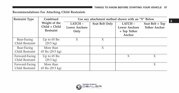
Recommendations For Attaching Child Restraints
Restraint Type CombinedWeight of theChild + Child
Restraint
Use any attachment method shown with an “X” BelowLATCH –
Lower AnchorsOnly
Seat Belt Only LATCH –Lower Anchors
+ Top TetherAnchor
Seat Belt + TopTether Anchor
Rear-FacingChild Restraint
Up to 65 lbs(29.5 kg)
X X
Rear-FacingChild Restraint
More than65 lbs (29.5 kg)
X
Forward-FacingChild Restraint
Up to 65 lbs(29.5 kg)
X X
Forward-FacingChild Restraint
More than65 lbs (29.5 kg)
X
2
THINGS TO KNOW BEFORE STARTING YOUR VEHICLE 97
Information Provided by:
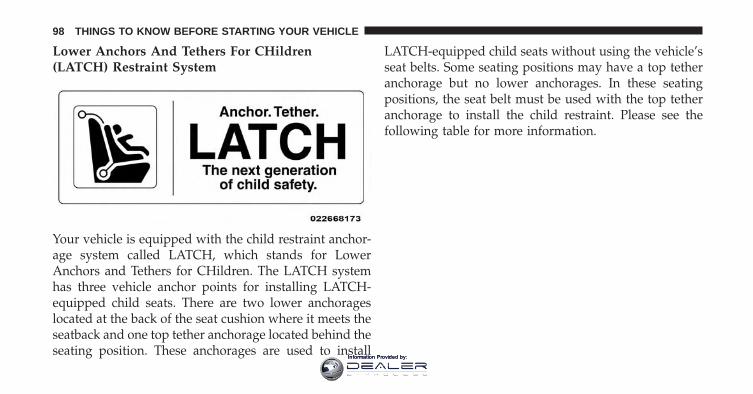
Lower Anchors And Tethers For CHildren(LATCH) Restraint System
Your vehicle is equipped with the child restraint anchor-age system called LATCH, which stands for LowerAnchors and Tethers for CHildren. The LATCH systemhas three vehicle anchor points for installing LATCH-equipped child seats. There are two lower anchorageslocated at the back of the seat cushion where it meets theseatback and one top tether anchorage located behind theseating position. These anchorages are used to install
LATCH-equipped child seats without using the vehicle’sseat belts. Some seating positions may have a top tetheranchorage but no lower anchorages. In these seatingpositions, the seat belt must be used with the top tetheranchorage to install the child restraint. Please see thefollowing table for more information.
98 THINGS TO KNOW BEFORE STARTING YOUR VEHICLE
Information Provided by:
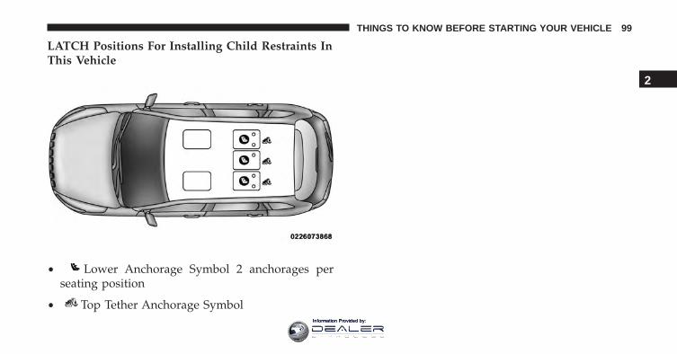
LATCH Positions For Installing Child Restraints InThis Vehicle
• Lower Anchorage Symbol 2 anchorages perseating position
• Top Tether Anchorage Symbol
2
THINGS TO KNOW BEFORE STARTING YOUR VEHICLE 99
Information Provided by:
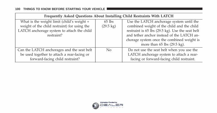
Frequently Asked Questions About Installing Child Restraints With LATCHWhat is the weight limit (child’s weight +weight of the child restraint) for using the
LATCH anchorage system to attach the childrestraint?
65 lbs(29.5 kg)
Use the LATCH anchorage system until thecombined weight of the child and the childrestraint is 65 lbs (29.5 kg). Use the seat beltand tether anchor instead of the LATCH an-chorage system once the combined weight is
more than 65 lbs (29.5 kg).Can the LATCH anchorages and the seat belt
be used together to attach a rear-facing orforward-facing child restraint?
No Do not use the seat belt when you use theLATCH anchorage system to attach a rear-
facing or forward-facing child restraint.
100 THINGS TO KNOW BEFORE STARTING YOUR VEHICLE
Information Provided by:
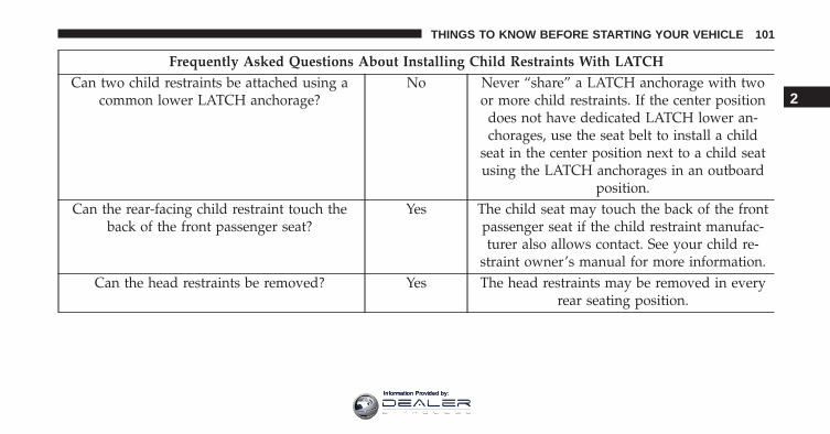
Frequently Asked Questions About Installing Child Restraints With LATCHCan two child restraints be attached using a
common lower LATCH anchorage?No Never “share” a LATCH anchorage with two
or more child restraints. If the center positiondoes not have dedicated LATCH lower an-chorages, use the seat belt to install a child
seat in the center position next to a child seatusing the LATCH anchorages in an outboard
position.Can the rear-facing child restraint touch the
back of the front passenger seat?Yes The child seat may touch the back of the front
passenger seat if the child restraint manufac-turer also allows contact. See your child re-
straint owner’s manual for more information.Can the head restraints be removed? Yes The head restraints may be removed in every
rear seating position.
2
THINGS TO KNOW BEFORE STARTING YOUR VEHICLE 101
Information Provided by:
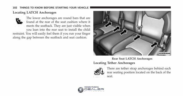
Locating LATCH Anchorages
The lower anchorages are round bars that arefound at the rear of the seat cushion where itmeets the seatback. They are just visible whenyou lean into the rear seat to install the child
restraint. You will easily feel them if you run your fingeralong the gap between the seatback and seat cushion.
Locating Tether Anchorages
There are tether strap anchorages behind eachrear seating position located on the back of theseat.
Rear Seat LATCH Anchorages
102 THINGS TO KNOW BEFORE STARTING YOUR VEHICLE
Information Provided by:
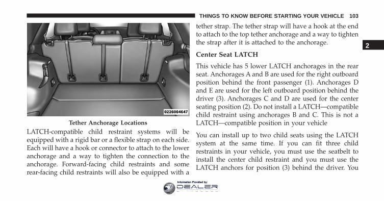
LATCH-compatible child restraint systems will beequipped with a rigid bar or a flexible strap on each side.Each will have a hook or connector to attach to the loweranchorage and a way to tighten the connection to theanchorage. Forward-facing child restraints and somerear-facing child restraints will also be equipped with a
tether strap. The tether strap will have a hook at the endto attach to the top tether anchorage and a way to tightenthe strap after it is attached to the anchorage.
Center Seat LATCH
This vehicle has 5 lower LATCH anchorages in the rearseat. Anchorages A and B are used for the right outboardposition behind the front passenger (1). Anchorages Dand E are used for the left outboard position behind thedriver (3). Anchorages C and D are used for the centerseating position (2). Do not install a LATCH—compatiblechild restraint using anchorages B and C. This is not aLATCH—compatible position in your vehicle
You can install up to two child seats using the LATCHsystem at the same time. If you can fit three childrestraints in your vehicle, you must use the seatbelt toinstall the center child restraint and you must use theLATCH anchors for position (3) behind the driver. You
Tether Anchorage Locations
2
THINGS TO KNOW BEFORE STARTING YOUR VEHICLE 103
Information Provided by:
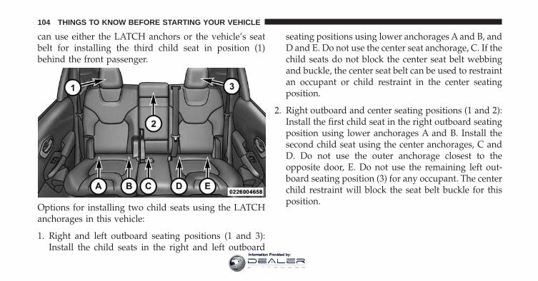
can use either the LATCH anchors or the vehicle’s seatbelt for installing the third child seat in position (1)behind the front passenger.
Options for installing two child seats using the LATCHanchorages in this vehicle:
1. Right and left outboard seating positions (1 and 3):Install the child seats in the right and left outboard
seating positions using lower anchorages A and B, andD and E. Do not use the center seat anchorage, C. If thechild seats do not block the center seat belt webbingand buckle, the center seat belt can be used to restraintan occupant or child restraint in the center seatingposition.
2. Right outboard and center seating positions (1 and 2):Install the first child seat in the right outboard seatingposition using lower anchorages A and B. Install thesecond child seat using the center anchorages, C andD. Do not use the outer anchorage closest to theopposite door, E. Do not use the remaining left out-board seating position (3) for any occupant. The centerchild restraint will block the seat belt buckle for thisposition.
104 THINGS TO KNOW BEFORE STARTING YOUR VEHICLE
Information Provided by:
WARNING!
• Use anchorages C and D to install a LATCH-compatible child restraint in the center seatingposition (2). Do not install a LATCH-compatiblechild restraint using anchorages B and C. This isnot a LATCH-compatible position in your vehicle.
• A child restraint installed in the center position (2)will block the seat belt buckle for the empty leftoutboard seat behind the driver (3). Do not use thisseat for another occupant.
• Never use the same lower anchorage to attach morethan one child restraint.
• If you are installing three child restraints next toeach other, you must use the seat belt and the centertether anchor for the center position. You must usethe LATCH anchors to install the child seat inposition (3), behind the driver. You may use either
(Continued)
WARNING! (Continued)the LATCH anchors or the vehicle’s seat belt forinstalling the child seat in position (1), behind thefront passenger. Please refer to “Installing theLATCH-Compatible Child Restraint System” fortypical installation instructions.
Always follow the directions of the child restraintmanufacturer when installing your child restraint.Not all child restraint systems will be installed asdescribed here.
To Install A LATCH-Compatible Child Restraint
If the selected seating position has a Switchable Auto-matic Locking Retractor (ALR) seat belt, stow the seatbelt, following the instructions below. See the section“Installing Child Restraints Using the Vehicle Seat Belt”to check what type of seat belt each seating position has.
2
THINGS TO KNOW BEFORE STARTING YOUR VEHICLE 105
Information Provided by:
1. Loosen the adjusters on the lower straps and on thetether strap of the child seat so that you can moreeasily attach the hooks or connectors to the vehicleanchorages.
2. Place the child seat between the lower anchorages forthat seating position. For some second row seats, youmay need to recline the seat and / or raise the headrestraint to get a better fit. If the rear seat can be movedforward and rearward in the vehicle, you may wish tomove it to its rear-most position to make room for thechild seat. You may also move the front seat forwardto allow more room for the child seat.
3. Attach the lower hooks or connectors of the childrestraint to the lower anchorages in the selected seat-ing position.
4. If the child restraint has a tether strap, connect it to thetop tether anchorage. See the section “Installing ChildRestraints Using the Top Tether Anchorage” for direc-tions to attach a tether anchor.
5. Tighten all of the straps as you push the child restraintrearward and downward into the seat. Remove slackin the straps according to the child restraint manufac-turer’s instructions.
6. Test that the child restraint is installed tightly bypulling back and forth on the child seat at the beltpath. It should not move more than 1 inch (25.4 mm)in any direction.
106 THINGS TO KNOW BEFORE STARTING YOUR VEHICLE
Information Provided by:
How To Stow An Unused ALR Seat Belt:
When using the LATCH attaching system to install a childrestraint, stow all ALR seat belts that are not being used byother occupants or being used to secure child restraints. Anunused belt could injure a child if they play with it andaccidentally lock the seat belt retractor. Before installing achild restraint using the LATCH system, buckle the seatbelt behind the child restraint and out of the child’s reach.If the buckled seat belt interferes with the child restraintinstallation, instead of buckling it behind the child re-straint, route the seat belt through the child restraint beltpath and then buckle it. Do not lock the seat belt. Remindall children in the vehicle that the seat belts are not toys andthat they should not play with them.
WARNING!
• Improper installation of a child restraint to theLATCH anchorages can lead to failure of the re-straint. The child could be badly injured or killed.Follow the child restraint manufacturer’s directionsexactly when installing an infant or child restraint.
• Child restraint anchorages are designed to with-stand only those loads imposed by correctly-fittedchild restraints. Under no circumstances are they tobe used for adult seat belts, harnesses, or forattaching other items or equipment to the vehicle.
2
THINGS TO KNOW BEFORE STARTING YOUR VEHICLE 107
Information Provided by:
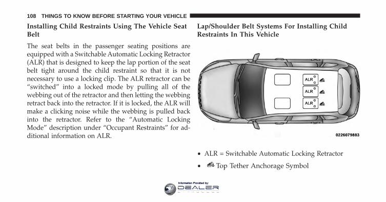
Installing Child Restraints Using The Vehicle SeatBelt
The seat belts in the passenger seating positions areequipped with a Switchable Automatic Locking Retractor(ALR) that is designed to keep the lap portion of the seatbelt tight around the child restraint so that it is notnecessary to use a locking clip. The ALR retractor can be“switched” into a locked mode by pulling all of thewebbing out of the retractor and then letting the webbingretract back into the retractor. If it is locked, the ALR willmake a clicking noise while the webbing is pulled backinto the retractor. Refer to the “Automatic LockingMode” description under “Occupant Restraints” for ad-ditional information on ALR.
Lap/Shoulder Belt Systems For Installing ChildRestraints In This Vehicle
• ALR = Switchable Automatic Locking Retractor
• Top Tether Anchorage Symbol
108 THINGS TO KNOW BEFORE STARTING YOUR VEHICLE
Information Provided by:
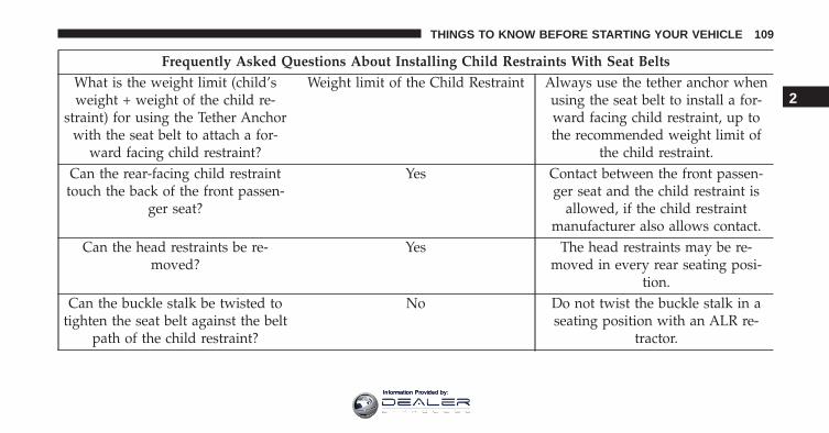
Frequently Asked Questions About Installing Child Restraints With Seat BeltsWhat is the weight limit (child’sweight + weight of the child re-
straint) for using the Tether Anchorwith the seat belt to attach a for-
ward facing child restraint?
Weight limit of the Child Restraint Always use the tether anchor whenusing the seat belt to install a for-ward facing child restraint, up tothe recommended weight limit of
the child restraint.Can the rear-facing child restraint
touch the back of the front passen-ger seat?
Yes Contact between the front passen-ger seat and the child restraint is
allowed, if the child restraintmanufacturer also allows contact.
Can the head restraints be re-moved?
Yes The head restraints may be re-moved in every rear seating posi-
tion.Can the buckle stalk be twisted to
tighten the seat belt against the beltpath of the child restraint?
No Do not twist the buckle stalk in aseating position with an ALR re-
tractor.
2
THINGS TO KNOW BEFORE STARTING YOUR VEHICLE 109
Information Provided by:
Installing A Child Restraint With A SwitchableAutomatic Locking Retractor (ALR)
1. Place the child seat in the center of the seatingposition. For some second row seats, you may need torecline the seat and/or raise the head restraint to get abetter fit. If the rear seat can be moved forward andrearward in the vehicle, you may wish to move it to itsrear-most position to make room for the child seat.You may also move the front seat forward to allowmore room for the child seat.
2. Pull enough of the seat belt webbing from the retractorto pass it through the belt path of the child restraint.Do not twist the belt webbing in the belt path.
3. Slide the latch plate into the buckle until you hear a“click.”
4. Pull on the webbing to make the lap portion tightagainst the child seat.
5. To lock the seat belt, pull down on the shoulder part ofthe belt until you have pulled all the seat belt webbingout of the retractor. Then, allow the webbing to retractback into the retractor. As the webbing retracts, youwill hear a clicking sound. This means the seat belt isnow in the Automatic Locking mode.
6. Try to pull the webbing out of the retractor. If it islocked, you should not be able to pull out any web-bing. If the retractor is not locked, repeat step 5.
7. Finally, pull up on any excess webbing to tighten thelap portion around the child restraint while you pushthe child restraint rearward and downward into thevehicle seat.
8. If the child restraint has a top tether strap and theseating position has a top tether anchorage, connectthe tether strap to the anchorage and tighten the tether
110 THINGS TO KNOW BEFORE STARTING YOUR VEHICLE
Information Provided by:
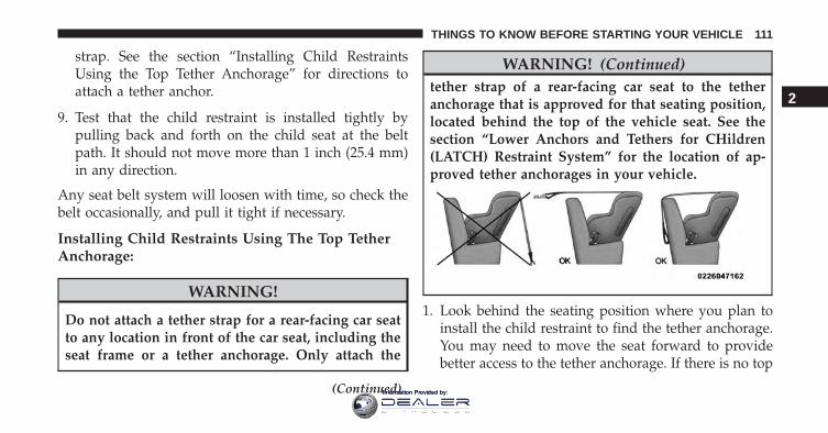
strap. See the section “Installing Child RestraintsUsing the Top Tether Anchorage” for directions toattach a tether anchor.
9. Test that the child restraint is installed tightly bypulling back and forth on the child seat at the beltpath. It should not move more than 1 inch (25.4 mm)in any direction.
Any seat belt system will loosen with time, so check thebelt occasionally, and pull it tight if necessary.
Installing Child Restraints Using The Top TetherAnchorage:
WARNING!
Do not attach a tether strap for a rear-facing car seatto any location in front of the car seat, including theseat frame or a tether anchorage. Only attach the
(Continued)
WARNING! (Continued)tether strap of a rear-facing car seat to the tetheranchorage that is approved for that seating position,located behind the top of the vehicle seat. See thesection “Lower Anchors and Tethers for CHildren(LATCH) Restraint System” for the location of ap-proved tether anchorages in your vehicle.
1. Look behind the seating position where you plan toinstall the child restraint to find the tether anchorage.You may need to move the seat forward to providebetter access to the tether anchorage. If there is no top
2
THINGS TO KNOW BEFORE STARTING YOUR VEHICLE 111
Information Provided by:
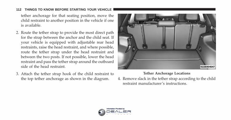
tether anchorage for that seating position, move thechild restraint to another position in the vehicle if oneis available.
2. Route the tether strap to provide the most direct pathfor the strap between the anchor and the child seat. Ifyour vehicle is equipped with adjustable rear headrestraints, raise the head restraint, and where possible,route the tether strap under the head restraint andbetween the two posts. If not possible, lower the headrestraint and pass the tether strap around the outboardside of the head restraint.
3. Attach the tether strap hook of the child restraint tothe top tether anchorage as shown in the diagram. 4. Remove slack in the tether strap according to the child
restraint manufacturer’s instructions.
Tether Anchorage Locations
112 THINGS TO KNOW BEFORE STARTING YOUR VEHICLE
Information Provided by:
WARNING!
• An incorrectly anchored tether strap could lead toincreased head motion and possible injury to thechild. Use only the anchorage position directlybehind the child seat to secure a child restraint toptether strap.
• If your vehicle is equipped with a split rear seat,make sure the tether strap does not slip into theopening between the seatbacks as you removeslack in the strap.
Transporting Pets
Air Bags deploying in the front seat could harm your pet.An unrestrained pet will be thrown about and possiblyinjured, or injure a passenger during panic braking or ina collision.
Pets should be restrained in the rear seat in pet harnessesor pet carriers that are secured by seat belts.
ENGINE BREAK-IN RECOMMENDATIONS
A long break-in period is not required for the engine anddrivetrain (transmission and axle) in your vehicle.
Drive moderately during the first 300 miles (500 km).After the initial 60 miles (100 km), speeds up to 50 or55 mph (80 or 90 km/h) are desirable.
While cruising, brief full-throttle acceleration within thelimits of local traffic laws contributes to a good break-in.Wide-open throttle acceleration in low gear can be detri-mental and should be avoided.
The engine oil installed in the engine at the factory is ahigh-quality energy conserving type lubricant. Oil changesshould be consistent with anticipated climate conditionsunder which vehicle operations will occur. For the recom-mended viscosity and quality grades, refer to “Mainte-nance Procedures” in “Maintaining Your Vehicle.”
2
THINGS TO KNOW BEFORE STARTING YOUR VEHICLE 113
Information Provided by:

CAUTION!
Never use Non-Detergent Oil or Straight Mineral Oilin the engine or damage may result.
NOTE: A new engine may consume some oil during itsfirst few thousand miles (kilometers) of operation. Thisshould be considered a normal part of the break-in andnot interpreted as a problem.
SAFETY TIPS
Transporting Passengers
NEVER TRANSPORT PASSENGERS IN THE CARGOAREA.
WARNING!
• Do not leave children or animals inside parkedvehicles in hot weather. Interior heat build-up maycause serious injury or death.
• It is extremely dangerous to ride in a cargo area,inside or outside of a vehicle. In a collision, peopleriding in these areas are more likely to be seriouslyinjured or killed.
• Do not allow people to ride in any area of yourvehicle that is not equipped with seats and seatbelts.
• Be sure everyone in your vehicle is in a seat andusing a seat belt properly.
114 THINGS TO KNOW BEFORE STARTING YOUR VEHICLE
Information Provided by:
Exhaust Gas
WARNING!
Exhaust gases can injure or kill. They contain carbonmonoxide (CO), which is colorless and odorless.Breathing it can make you unconscious and caneventually poison you. To avoid breathing (CO),follow these safety tips:• Do not run the engine in a closed garage or in
confined areas any longer than needed to moveyour vehicle in or out of the area.
• If you are required to drive with the trunk/liftgate/rear doors open, make sure that all win-dows are closed and the climate control BLOWERswitch is set at high speed. DO NOT use therecirculation mode.
(Continued)
WARNING! (Continued)• If it is necessary to sit in a parked vehicle with the
engine running, adjust your heating or coolingcontrols to force outside air into the vehicle. Set theblower at high speed.
The best protection against carbon monoxide entry intothe vehicle body is a properly maintained engine exhaustsystem.
Whenever a change is noticed in the sound of the exhaustsystem, when exhaust fumes can be detected inside thevehicle, or when the underside or rear of the vehicle isdamaged, have a competent mechanic inspect the com-plete exhaust system and adjacent body areas for broken,damaged, deteriorated, or mispositioned parts. Openseams or loose connections could permit exhaust fumesto seep into the passenger compartment. In addition,inspect the exhaust system each time the vehicle is raisedfor lubrication or oil change. Replace as required.
2
THINGS TO KNOW BEFORE STARTING YOUR VEHICLE 115
Information Provided by:
Safety Checks You Should Make Inside TheVehicle
Seat Belts
Inspect the seat belt system periodically, checking forcuts, frays, and loose parts. Damaged parts must bereplaced immediately. Do not disassemble or modify thesystem.
Front seat belt assemblies must be replaced after acollision. Rear seat belt assemblies must be replaced aftera collision if they have been damaged (i.e., bent retractor,torn webbing, etc.). If there is any question regarding seatbelt or retractor condition, replace the seat belt.
Air Bag Warning Light
The Air Bag warning light will turn on for four toeight seconds as a bulb check when the ignition switchis first turned to ON/RUN. If the light is either not onduring starting, stays on, or turns on while driving,
have the system inspected at an authorized dealer assoon as possible. This light will illuminate with asingle chime when a fault with the Air Bag WarningLight has been detected, it will stay on until the faultis cleared. If the light comes on intermittently orremains on while driving, have an authorized dealerservice the vehicle immediately. Refer to “OccupantRestraints” in “Things To Know Before Starting YourVehicle” for further information.
Defroster
Check operation by selecting the defrost mode and placethe blower control on high speed. You should be able to feelthe air directed against the windshield. See your autho-rized dealer for service if your defroster is inoperable.
Floor Mat Safety Information
Always use floor mats designed to fit the footwell of yourvehicle. Use only floor mats that leave the pedal areaunobstructed and that are firmly secured so that they
116 THINGS TO KNOW BEFORE STARTING YOUR VEHICLE
Information Provided by:
cannot slip out of position and interfere with the pedalsor impair safe operation of your vehicle in other ways.
WARNING!
Pedals that cannot move freely can cause loss ofvehicle control and increase the risk of serious per-sonal injury.• Always make sure that floor mats are properly
attached to the floor mat fasteners.• Never place or install floor mats or other floor cover-
ings in the vehicle that cannot be properly secured toprevent them from moving and interfering with thepedals or the ability to control the vehicle.
• Never put floor mats or other floor coverings on topof already installed floor mats. Additional floormats and other coverings will reduce the size of thepedal area and interfere with the pedals.
(Continued)
WARNING! (Continued)• Check mounting of mats on a regular basis. Always
properly reinstall and secure floor mats that havebeen removed for cleaning.
• Always make sure that objects cannot fall into thedriver footwell while the vehicle is moving. Ob-jects can become trapped under the brake pedaland accelerator pedal causing a loss of vehiclecontrol.
• If required, mounting posts must be properly in-stalled, if not equipped from the factory.
Failure to properly follow floor mat installation ormounting can cause interference with the brakepedal and accelerator pedal operation causing loss ofcontrol of the vehicle.
2
THINGS TO KNOW BEFORE STARTING YOUR VEHICLE 117
Information Provided by:
Periodic Safety Checks You Should Make OutsideThe Vehicle
Tires
Examine tires for excessive tread wear and uneven wearpatterns. Check for stones, nails, glass, or other objectslodged in the tread or sidewall. Inspect the tread for cutsand cracks. Inspect sidewalls for cuts, cracks, and bulges.Check the wheel nuts for tightness. Check the tires(including spare) for proper cold inflation pressure.
Lights
Have someone observe the operation of brake lights andexterior lights while you work the controls. Check turnsignal and high beam indicator lights on the instrumentpanel.
Door Latches
Check for proper closing, latching, and locking.
Fluid Leaks
Check area under vehicle after overnight parking for fuel,engine coolant, oil, or other fluid leaks. Also, if gasolinefumes are detected, or if fuel or brake fluid leaks aresuspected, the cause should be located and correctedimmediately.
118 THINGS TO KNOW BEFORE STARTING YOUR VEHICLE
Information Provided by:
UNDERSTANDING THE FEATURES OF YOUR VEHICLE
CONTENTS� MIRRORS . . . . . . . . . . . . . . . . . . . . . . . . . . . .126
▫ Inside Day/Night Mirror — If Equipped . . . .126
▫ Assist And 9–1–1 Rearview Mirror — IfEquipped . . . . . . . . . . . . . . . . . . . . . . . . . . .126
▫ Outside Mirrors . . . . . . . . . . . . . . . . . . . . . .133
▫ Power Mirrors . . . . . . . . . . . . . . . . . . . . . . .134
▫ Power Folding Mirrors — If Equipped. . . . . . .135
▫ Heated Mirrors — If Equipped . . . . . . . . . . .136
▫ Illuminated Vanity Mirrors — If Equipped . . .136
▫ Sun Visor “Slide-On-Rod” Feature — IfEquipped . . . . . . . . . . . . . . . . . . . . . . . . . . .137
� BLIND SPOT MONITORING (BSM) — IFEQUIPPED . . . . . . . . . . . . . . . . . . . . . . . . . . .137
▫ Rear Cross Path (RCP) . . . . . . . . . . . . . . . . .143
▫ Modes Of Operation . . . . . . . . . . . . . . . . . . .145
▫ General Information. . . . . . . . . . . . . . . . . . . .146
� SEATS . . . . . . . . . . . . . . . . . . . . . . . . . . . . . .146
▫ Power Seats — If Equipped . . . . . . . . . . . . . .147
▫ Manual Seats — If Equipped . . . . . . . . . . . . .148
▫ Front Heated Seats — If Equipped . . . . . . . . .151
▫ Front Ventilated Seats — If Equipped . . . . . . .152
3
Information Provided by:
▫ Head Restraints . . . . . . . . . . . . . . . . . . . . . .153
▫ 60/40 Split Folding Rear Seat With Fold-FlatFeature . . . . . . . . . . . . . . . . . . . . . . . . . . . .157
� DRIVER MEMORY SEAT — IF EQUIPPED . . . .160
▫ Programming The Memory Feature . . . . . . . . .160
▫ Linking And Unlinking The Remote KeylessEntry Transmitter To Memory . . . . . . . . . . . . .161
▫ Memory Position Recall . . . . . . . . . . . . . . . . .162
▫ Easy Entry/Exit Seat . . . . . . . . . . . . . . . . . . .163
� TO OPEN AND CLOSE THE HOOD . . . . . . . . .164
� LIGHTS . . . . . . . . . . . . . . . . . . . . . . . . . . . . .165
▫ Headlight Switch . . . . . . . . . . . . . . . . . . . . .165
▫ Automatic Headlights — If Equipped . . . . . . .166
▫ Headlights On With Wipers (Available WithAutomatic Headlights Only) . . . . . . . . . . . . .166
▫ Headlight Time Delay . . . . . . . . . . . . . . . . . .167
▫ Automatic High Beam Headlamp Control — IfEquipped . . . . . . . . . . . . . . . . . . . . . . . . . . .168
▫ Daytime Running Lights (DRL) — IfEquipped . . . . . . . . . . . . . . . . . . . . . . . . . . .168
▫ Lights-On Reminder . . . . . . . . . . . . . . . . . . .169
▫ Fog Lights — If Equipped . . . . . . . . . . . . . . .169
▫ Multifunction Lever . . . . . . . . . . . . . . . . . . .170
▫ Turn Signals . . . . . . . . . . . . . . . . . . . . . . . . .170
▫ Lane Change Assist . . . . . . . . . . . . . . . . . . .171
▫ High/Low Beam Switch . . . . . . . . . . . . . . . .171
120 UNDERSTANDING THE FEATURES OF YOUR VEHICLE
Information Provided by:
▫ Flash-To-Pass . . . . . . . . . . . . . . . . . . . . . . . .171
▫ Front Map/Reading Lights . . . . . . . . . . . . . . .171
▫ Interior Lights . . . . . . . . . . . . . . . . . . . . . . .172
▫ Battery Saver Feature . . . . . . . . . . . . . . . . . .174
� WINDSHIELD WIPERS AND WASHERS . . . . . .174
▫ Windshield Wiper Operation . . . . . . . . . . . . .175
▫ Intermittent Wiper System . . . . . . . . . . . . . . .176
▫ Windshield Washer Operation. . . . . . . . . . . . .176
▫ Mist . . . . . . . . . . . . . . . . . . . . . . . . . . . . . . .177
▫ Windshield Wiper De-Icer — If Equipped . . . .178
▫ Rain Sensing Wipers — If Equipped . . . . . . . .179
� TILT/TELESCOPING STEERINGCOLUMN . . . . . . . . . . . . . . . . . . . . . . . . . . . .180
� HEATED STEERING WHEEL — IFEQUIPPED . . . . . . . . . . . . . . . . . . . . . . . . . . .181
� ELECTRONIC SPEED CONTROL — IFEQUIPPED . . . . . . . . . . . . . . . . . . . . . . . . . . .183
▫ To Activate . . . . . . . . . . . . . . . . . . . . . . . . . .184
▫ To Set A Desired Speed . . . . . . . . . . . . . . . . .184
▫ To Deactivate . . . . . . . . . . . . . . . . . . . . . . . .185
▫ To Resume Speed . . . . . . . . . . . . . . . . . . . . .185
▫ To Vary The Speed Setting . . . . . . . . . . . . . . .185
▫ To Accelerate For Passing . . . . . . . . . . . . . . .186
� ADAPTIVE CRUISE CONTROL (ACC) — IFEQUIPPED . . . . . . . . . . . . . . . . . . . . . . . . . . .187
▫ Adaptive Cruise Control (ACC) Operation . . . .189
▫ Activating Adaptive Cruise Control (ACC). . . .190
3
UNDERSTANDING THE FEATURES OF YOUR VEHICLE 121
Information Provided by:
▫ To Activate/Deactivate. . . . . . . . . . . . . . . . . .191
▫ To Set A Desired ACC Speed . . . . . . . . . . . . .192
▫ To Cancel . . . . . . . . . . . . . . . . . . . . . . . . . . .193
▫ To Turn Off . . . . . . . . . . . . . . . . . . . . . . . . . .193
▫ To Resume . . . . . . . . . . . . . . . . . . . . . . . . . .194
▫ To Vary The Speed Setting . . . . . . . . . . . . . . .194
▫ Setting The Following Distance In ACC . . . . . .197
▫ Overtake Aid . . . . . . . . . . . . . . . . . . . . . . . .201
▫ ACC Operation At Stop . . . . . . . . . . . . . . . . .201
▫ Adaptive Cruise Control (ACC) Menu . . . . . . .202
▫ Display Warnings And Maintenance . . . . . . . .203
▫ Precautions While Driving With ACC . . . . . . .206
▫ General Information. . . . . . . . . . . . . . . . . . . .210
▫ Normal (Fixed Speed) Electronic SpeedControl Mode . . . . . . . . . . . . . . . . . . . . . . . .210
� FORWARD COLLISION WARNING (FCW)WITH MITIGATION — IF EQUIPPED . . . . . . .214
▫ Forward Collision Warning (FCW) WithMitigation Operation . . . . . . . . . . . . . . . . . . .214
▫ Turning FCW ON Or OFF . . . . . . . . . . . . . . .216
▫ Changing FCW And Active Braking Status. . . .217
▫ FCW Limited Warning . . . . . . . . . . . . . . . . . .218
▫ Service FCW Warning . . . . . . . . . . . . . . . . . .218
� LANESENSE — IF EQUIPPED . . . . . . . . . . . . .218
▫ LaneSense Operation . . . . . . . . . . . . . . . . . . .218
▫ Turning LaneSense ON Or OFF. . . . . . . . . . . .219
▫ LaneSense Warning Message. . . . . . . . . . . . . .221
122 UNDERSTANDING THE FEATURES OF YOUR VEHICLE
Information Provided by:
▫ Changing LaneSense Status . . . . . . . . . . . . . .229
� PARKSENSE REAR PARK ASSIST — IFEQUIPPED . . . . . . . . . . . . . . . . . . . . . . . . . . .229
▫ ParkSense Sensors . . . . . . . . . . . . . . . . . . . . .230
▫ ParkSense Warning Display . . . . . . . . . . . . . .230
▫ ParkSense Display . . . . . . . . . . . . . . . . . . . . .231
▫ Enabling And Disabling ParkSense . . . . . . . . .235
▫ Service The ParkSense Rear Park AssistSystem . . . . . . . . . . . . . . . . . . . . . . . . . . . . .236
▫ Cleaning The ParkSense System . . . . . . . . . . .237
▫ ParkSense System Usage Precautions . . . . . . . .237
� PARKSENSE FRONT AND REAR PARKASSIST — IF EQUIPPED . . . . . . . . . . . . . . . . .239
▫ ParkSense Sensors . . . . . . . . . . . . . . . . . . . . .241
▫ ParkSense Warning Display . . . . . . . . . . . . . .241
▫ ParkSense Display . . . . . . . . . . . . . . . . . . . . .242
▫ Enabling And Disabling ParkSense . . . . . . . . .251
▫ Service The ParkSense Park Assist System . . . .252
▫ Cleaning The ParkSense System . . . . . . . . . . .253
▫ ParkSense System Usage Precautions . . . . . . . .253
� PARKSENSE ACTIVE PARK ASSISTSYSTEM — IF EQUIPPED . . . . . . . . . . . . . . . .256
▫ Enabling And Disabling The ParkSense ActivePark Assist System. . . . . . . . . . . . . . . . . . . . .257
▫ Parallel Parking Space AssistanceOperation/Display. . . . . . . . . . . . . . . . . . . . .259
▫ Perpendicular Parking Space AssistanceOperation/Display. . . . . . . . . . . . . . . . . . . . .268
3
UNDERSTANDING THE FEATURES OF YOUR VEHICLE 123
Information Provided by:
� PARKVIEW REAR BACK UP CAMERA — IFEQUIPPED . . . . . . . . . . . . . . . . . . . . . . . . . . .280
� GARAGE DOOR OPENER — IF EQUIPPED . . .282
▫ Before You Begin Programming HomeLink . . .283
▫ Programming A Rolling Code . . . . . . . . . . . . .284
▫ Programming A Non-Rolling Code . . . . . . . . .286
▫ Canadian/Gate Operator Programming . . . . . .287
▫ Using HomeLink . . . . . . . . . . . . . . . . . . . . .289
▫ Security . . . . . . . . . . . . . . . . . . . . . . . . . . . .289
▫ Troubleshooting Tips . . . . . . . . . . . . . . . . . . .289
▫ General Information. . . . . . . . . . . . . . . . . . . .290
� POWER SUNROOF WITH POWER SHADE — IFEQUIPPED . . . . . . . . . . . . . . . . . . . . . . . . . . .291
▫ Opening Sunroof — Express . . . . . . . . . . . . . .293
▫ Opening Sunroof — Manual Mode . . . . . . . . .293
▫ Closing Sunroof — Express. . . . . . . . . . . . . . .293
▫ Closing Sunroof — Manual Mode . . . . . . . . . .294
▫ Venting Sunroof — Express . . . . . . . . . . . . . .294
▫ Opening Power Shade — Express . . . . . . . . . .294
▫ Opening Power Shade — Manual Mode . . . . .294
▫ Closing Power Shade — Express . . . . . . . . . . .295
▫ Closing Power Shade — Manual Mode . . . . . .295
▫ Pinch Protect Feature . . . . . . . . . . . . . . . . . . .295
▫ Wind Buffeting . . . . . . . . . . . . . . . . . . . . . . .295
▫ Sunroof Maintenance . . . . . . . . . . . . . . . . . . .296
▫ Ignition OFF Operation . . . . . . . . . . . . . . . . .296
� POWER OUTLETS . . . . . . . . . . . . . . . . . . . . .296
124 UNDERSTANDING THE FEATURES OF YOUR VEHICLE
Information Provided by:
� POWER INVERTER — IF EQUIPPED . . . . . . . .300
� WIRELESS CHARGING PAD — IFEQUIPPED . . . . . . . . . . . . . . . . . . . . . . . . . . .302
▫ Wireless Charging Pad Operation . . . . . . . . . .303
� CUPHOLDERS . . . . . . . . . . . . . . . . . . . . . . . .305
� STORAGE . . . . . . . . . . . . . . . . . . . . . . . . . . . .306
▫ Glove Compartment . . . . . . . . . . . . . . . . . . .306
▫ Console Storage Compartment . . . . . . . . . . . .307
▫ Flip ’n Stow Front Passenger Seat Storage — IfEquipped . . . . . . . . . . . . . . . . . . . . . . . . . . .308
� CARGO AREA FEATURES . . . . . . . . . . . . . . . .309
▫ Cargo Load Floor . . . . . . . . . . . . . . . . . . . . .309
▫ Cargo Extension Panels . . . . . . . . . . . . . . . . .310
▫ Cargo Tie-Down Hooks And Loops . . . . . . . .310
▫ Rear Storage Bins. . . . . . . . . . . . . . . . . . . . . .311
� REAR WINDOW FEATURES . . . . . . . . . . . . . .312
▫ Rear Window Wiper/Washer . . . . . . . . . . . . .312
▫ Rear Window Defroster . . . . . . . . . . . . . . . . .313
� ROOF LUGGAGE RACK — IF EQUIPPED . . . .314
3
UNDERSTANDING THE FEATURES OF YOUR VEHICLE 125
Information Provided by:
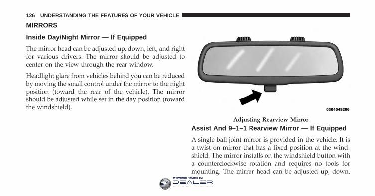
MIRRORS
Inside Day/Night Mirror — If Equipped
The mirror head can be adjusted up, down, left, and rightfor various drivers. The mirror should be adjusted tocenter on the view through the rear window.
Headlight glare from vehicles behind you can be reducedby moving the small control under the mirror to the nightposition (toward the rear of the vehicle). The mirrorshould be adjusted while set in the day position (towardthe windshield).
Assist And 9–1–1 Rearview Mirror — If Equipped
A single ball joint mirror is provided in the vehicle. It isa twist on mirror that has a fixed position at the wind-shield. The mirror installs on the windshield button witha counterclockwise rotation and requires no tools formounting. The mirror head can be adjusted up, down,
Adjusting Rearview Mirror
126 UNDERSTANDING THE FEATURES OF YOUR VEHICLE
Information Provided by:
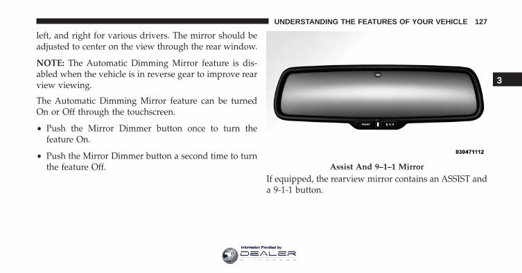
left, and right for various drivers. The mirror should beadjusted to center on the view through the rear window.
NOTE: The Automatic Dimming Mirror feature is dis-abled when the vehicle is in reverse gear to improve rearview viewing.
The Automatic Dimming Mirror feature can be turnedOn or Off through the touchscreen.
• Push the Mirror Dimmer button once to turn thefeature On.
• Push the Mirror Dimmer button a second time to turnthe feature Off.
If equipped, the rearview mirror contains an ASSIST anda 9-1-1 button.
Assist And 9–1–1 Mirror
3
UNDERSTANDING THE FEATURES OF YOUR VEHICLE 127
Information Provided by:
WARNING!
ALWAYS obey traffic laws and pay attention to theroad. Some Uconnect Access services, including 9-1-1and Assist, will NOT work without an operable 1X(voice/data) or 3G (data) network connection.
NOTE:
• Your vehicle may be transmitting data as authorizedby the subscriber.
• The 9–1–1 and ASSIST buttons will only function ifyou are connected to an operable 1X (voice/data) or3G (data) network. Other Uconnect services will onlybe operable if your Uconnect Access service is activeand you are connected to an operable 1X (voice/data)or 3G (data) network.
ASSIST Call
The ASSIST Button is used to automatically connect youto any one of the following support centers:
• Roadside Assistance – If you get a flat tire, or need atow, just push the ASSIST button and you’ll be con-nected to someone who can help. Roadside Assistancewill know what vehicle you’re driving and its location.Additional fees may apply for roadside Assistance.
• Uconnect Access Customer Care – In-vehicle supportfor Uconnect Access and Uconnect Access Via Mobilefeatures.
• Vehicle Customer Care – Total support for all othervehicle issues.
9-1-1 Call
1. Push the 9-1-1 Call button on the Rearview Mirror.
128 UNDERSTANDING THE FEATURES OF YOUR VEHICLE
Information Provided by:
NOTE: In case the 9-1-1 Call button is pushed in error,there will be a 10 second delay before the 9-1-1 Callsystem initiates a call to a 9-1-1 operator. To cancel the9-1-1 Call connection, push the 9-1-1 Call button on theRearview Mirror or press the cancellation button on theDevice Screen. Termination of the 9-1-1 Call will turn thegreen LED light on the Rearview Mirror off.
2. The LED light located between the ASSIST and 9-1-1buttons on the Rearview Mirror will turn green once aconnection to a 9-1-1 operator has been made.
3. Once a connection between the vehicle and a 9-1-1operator is made, the 9-1-1 Call system may transmitthe following important vehicle information to a 9-1-1operator:
• Indication that the occupant placed a 9-1-1 Call.
• The vehicle brand.
• The last known GPS coordinates of the vehicle.
4. You should be able to speak with the 9-1-1 operatorthrough the vehicle audio system to determine ifadditional help is needed.
WARNING!
ALWAYS obey traffic laws and pay attention to theroad. Some Uconnect Access services, including 9-1-1and Assist, will NOT work without an operable 1X(voice/data) or 3G (data) network connection.
3
UNDERSTANDING THE FEATURES OF YOUR VEHICLE 129
Information Provided by:
NOTE:
• Your vehicle may be transmitting data as authorizedby the subscriber.
• Once a connection is made between the vehicle’s9-1-1 Call system and the 9-1-1 operator, the 9-1-1operator may be able to open a voice connection withthe vehicle to determine if additional help is needed.Once the 9-1-1 operator opens a voice connectionwith the vehicle’s 9-1-1 Call system, the operatorshould be able to speak with you or other vehicleoccupants and hear sounds occurring in the vehicle.The vehicle’s 9-1-1 Call system will attempt to re-main connected with the 9-1-1 operator until the9-1-1 operator terminates the connection.
5. The 9-1-1 operator may attempt to contact appropriateemergency responders and provide them with impor-tant vehicle information and GPS coordinates.
WARNING!
• If anyone in the vehicle could be in danger (e.g.,fire or smoke is visible, dangerous road conditionsor location), do not wait for voice contact from a9-1-1 operator. All occupants should exit the vehicleimmediately and move to a safe location.
• Never place anything on or near the vehicle’soperable 1X (voice/data) or 3G(data) network andGPS antennas. You could prevent operable 1X(voice/data) or 3G(data) network and GPS signalreception, which can prevent your vehicle fromplacing an emergency call. An operable 1X (voice/data) or 3G(data) network and GPS signal recep-tion is required for the 9-1-1 Call system to functionproperly.
• The 9-1-1 Call system is embedded into the vehi-cle’s electrical system. Do not add aftermarket
(Continued)
130 UNDERSTANDING THE FEATURES OF YOUR VEHICLE
Information Provided by:
WARNING! (Continued)electrical equipment to the vehicle’s electrical sys-tem. This may prevent your vehicle from sending asignal to initiate an emergency call. To avoid inter-ference that can cause the 9-1-1 Call system to fail,never add aftermarket equipment (e.g., two-waymobile radio, CB radio, data recorder, etc.) to yourvehicle’s electrical system or modify the antennason your vehicle. IF YOUR VEHICLE LOSES BAT-TERY POWER FOR ANY REASON (INCLUDINGDURING OR AFTER AN ACCIDENT), THEUCONNECT FEATURES, APPS AND SERVICES,AMONG OTHERS, WILL NOT OPERATE.
• Modifications to any part of the 9-1-1 Call systemcould cause the air bag system to fail when youneed it. You could be injured if the air bag systemis not there to help protect you.
9-1-1 Call System Limitations
Vehicles sold in Canada and Mexico DO NOT have 9-1-1Call system capabilities.
9-1-1 or other emergency line operators in Canada andMexico may not answer or respond to 9-1-1 system calls.
If the 9-1-1 Call system detects a malfunction, any of thefollowing may occur at the time the malfunction isdetected, and at the beginning of each ignition cycle:
• The Rearview Mirror light located between the ASSISTand 9-1-1 buttons will continuously be illuminated red.
• The Device Screen will display the following message“Vehicle device requires service. Please contact yourdealer.”
• An In-Vehicle Audio message will state “Vehicle de-vice requires service. Please contact your dealer.”
3
UNDERSTANDING THE FEATURES OF YOUR VEHICLE 131
Information Provided by:
WARNING!
• Ignoring the Rearview Mirror light could mean youwill not have 9-1-1 Call services. If the RearviewMirror light is illuminated, have an authorizeddealer service the 9-1-1 Call system immediately.
• The Occupant Restraint Control module turns onthe air bag Warning Light on the instrument panelif a malfunction in any part of the system isdetected. If the Air Bag Warning Light is illumi-nated, have an authorized dealer service the Occu-pant Restraint Control system immediately.
Even if the 9-1-1 Call system is fully functional, factorsbeyond FCA US LLC’s control may prevent or stop the9-1-1 Call system operation. These include, but are notlimited to, the following factors:
• The ignition key has been removed from the ignitionand the delayed accessories mode is active.
• The ignition key is in OFF position.
• The vehicle’s electrical systems are not intact.
• The 9-1-1 Call system software and/or hardware aredamaged during a crash.
• The vehicle battery loses power or becomes discon-nected during a vehicle crash.
• 1X (voice/data) or 3G (data) network and/or GlobalPositioning Satellite signals are unavailable or ob-structed.
• Equipment malfunction at the 9-1-1 operator facility.
• Operator error by the 9-1-1 operator.
• 1X (voice/data) or 3G (data) network congestion.
• Weather.
• Buildings, structures, geographic terrain, or tunnels.
132 UNDERSTANDING THE FEATURES OF YOUR VEHICLE
Information Provided by:
WARNING!
ALWAYS obey traffic laws and pay attention to theroad. Some Uconnect Access services, including 9-1-1and Assist, will NOT work without an operable 1X(voice/data) or 3G (data) network connection.
NOTE:
• Your vehicle may be transmitting data as authorizedby the subscriber.
• Never place anything on or near the vehicle’s 1X(voice/data) or 3G (data) and GPS antennas. You couldprevent 1X (voice/data) or 3G (data) and GPS signalreception, which can prevent your vehicle from plac-ing an emergency call. An operable 1X (voice/data) or3G (data) network connection and a GPS signal isrequired for the 9-1-1 Call system to function properly.
General Information
This device complies with Part 15 of the FCC Rules.Operation is subject to the following two conditions:(1) This device may not cause harmful interference,and (2) this device must accept any interference re-ceived, including interference that may cause unde-sired operation.
CAUTION!
To avoid damage to the mirror during cleaning, neverspray any cleaning solution directly onto the mirror.Apply the solution onto a clean cloth and wipe themirror clean.
Outside Mirrors
To receive maximum benefit, adjust the outside mirror(s)to center on the adjacent lane of traffic and a slightoverlap of the view obtained from the inside mirror.
3
UNDERSTANDING THE FEATURES OF YOUR VEHICLE 133
Information Provided by:
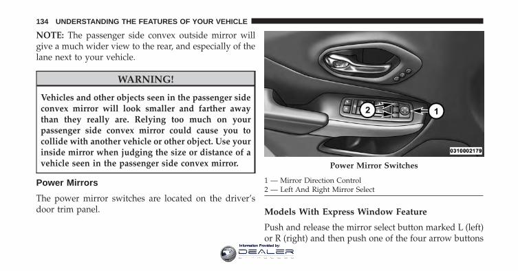
NOTE: The passenger side convex outside mirror willgive a much wider view to the rear, and especially of thelane next to your vehicle.
WARNING!
Vehicles and other objects seen in the passenger sideconvex mirror will look smaller and farther awaythan they really are. Relying too much on yourpassenger side convex mirror could cause you tocollide with another vehicle or other object. Use yourinside mirror when judging the size or distance of avehicle seen in the passenger side convex mirror.
Power Mirrors
The power mirror switches are located on the driver’sdoor trim panel. Models With Express Window Feature
Push and release the mirror select button marked L (left)or R (right) and then push one of the four arrow buttons
Power Mirror Switches
1 — Mirror Direction Control2 — Left And Right Mirror Select
134 UNDERSTANDING THE FEATURES OF YOUR VEHICLE
Information Provided by:
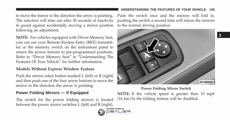
to move the mirror in the direction the arrow is pointing.The selection will time out after 30 seconds of inactivityto guard against accidentally moving a mirror positionfollowing an adjustment.
NOTE: For vehicles equipped with Driver Memory Seat,you can use your Remote Keyless Entry (RKE) transmit-ter or the memory switch on the instrument panel toreturn the power mirrors to pre-programmed positions.Refer to “Driver Memory Seat” in “Understanding TheFeatures Of Your Vehicle” for further information.
Models Without Express Window Feature
Push the mirror select button marked L (left) or R (right)and then push one of the four arrow buttons to move themirror in the direction the arrow is pointing.
Power Folding Mirrors — If Equipped
The switch for the power folding mirrors is locatedbetween the power mirror switches L (left) and R (right).
Push the switch once and the mirrors will fold in,pushing the switch a second time will return the mirrorsto the normal driving position.
NOTE: If the vehicle speed is greater than 10 mph(16 km/h) the folding feature will be disabled.
Power Folding Mirror Switch
3
UNDERSTANDING THE FEATURES OF YOUR VEHICLE 135
Information Provided by:
If the mirrors are in the folded position, and vehiclespeed is equal or greater than 10 mph (16 km/h), theywill automatically unfold.
Resetting The Power Folding Outside Mirrors
You may need to reset the power folding mirrors if thefollowing occurs:
• The mirrors are accidentally blocked while folding.
• The mirrors are accidentally manually folded/unfolded.
• The mirrors come out of the unfolded position.
• The mirrors shake and vibrate at normal drivingspeeds.
To reset the power folding mirrors: Fold and unfold themby pushing the button. (this may require multiple buttonpushes). This resets them to their normal position.
Heated Mirrors — If Equipped
These mirrors are heated to melt frost or ice. Thisfeature can be activated whenever you turn on the
rear window defroster (if equipped). Refer to “RearWindow Features” in “Understanding The Features OfYour Vehicle” for further information.
Illuminated Vanity Mirrors — If Equipped
An illuminated vanity mirror is on each sun visor. To usethe mirror, rotate the sun visor down and swing themirror cover upward. The lights will turn on automati-cally. Closing the mirror cover will turn off the light.
136 UNDERSTANDING THE FEATURES OF YOUR VEHICLE
Information Provided by:
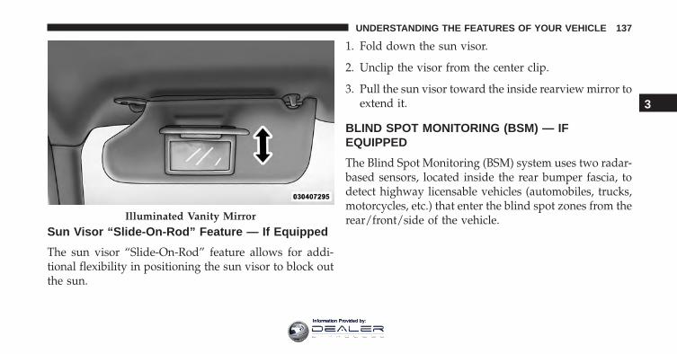
Sun Visor “Slide-On-Rod” Feature — If Equipped
The sun visor “Slide-On-Rod” feature allows for addi-tional flexibility in positioning the sun visor to block outthe sun.
1. Fold down the sun visor.
2. Unclip the visor from the center clip.
3. Pull the sun visor toward the inside rearview mirror toextend it.
BLIND SPOT MONITORING (BSM) — IFEQUIPPED
The Blind Spot Monitoring (BSM) system uses two radar-based sensors, located inside the rear bumper fascia, todetect highway licensable vehicles (automobiles, trucks,motorcycles, etc.) that enter the blind spot zones from therear/front/side of the vehicle.Illuminated Vanity Mirror
3
UNDERSTANDING THE FEATURES OF YOUR VEHICLE 137
Information Provided by:
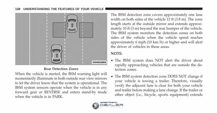
When the vehicle is started, the BSM warning light willmomentarily illuminate in both outside rear view mirrorsto let the driver know that the system is operational. TheBSM system sensors operate when the vehicle is in anyforward gear or REVERSE and enters stand-by modewhen the vehicle is in PARK.
The BSM detection zone covers approximately one lanewidth on both sides of the vehicle 12 ft (3.8 m). The zonelength starts at the outside mirror and extends approxi-mately 10 ft (3 m) beyond the rear bumper of the vehicle.The BSM system monitors the detection zones on bothsides of the vehicle when the vehicle speed reachesapproximately 6 mph (10 km/h) or higher and will alertthe driver of vehicles in these areas.
NOTE:
• The BSM system does NOT alert the driver aboutrapidly approaching vehicles that are outside the de-tection zones.
• The BSM system detection zone DOES NOT change ifyour vehicle is towing a trailer. Therefore, visuallyverify the adjacent lane is clear for both your vehicleand trailer before making a lane change. If the trailer orother object (i.e., bicycle, sports equipment) extends
Rear Detection Zones
138 UNDERSTANDING THE FEATURES OF YOUR VEHICLE
Information Provided by:
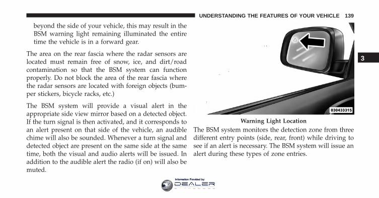
beyond the side of your vehicle, this may result in theBSM warning light remaining illuminated the entiretime the vehicle is in a forward gear.
The area on the rear fascia where the radar sensors arelocated must remain free of snow, ice, and dirt/roadcontamination so that the BSM system can functionproperly. Do not block the area of the rear fascia wherethe radar sensors are located with foreign objects (bum-per stickers, bicycle racks, etc.)
The BSM system will provide a visual alert in theappropriate side view mirror based on a detected object.If the turn signal is then activated, and it corresponds toan alert present on that side of the vehicle, an audiblechime will also be sounded. Whenever a turn signal anddetected object are present on the same side at the sametime, both the visual and audio alerts will be issued. Inaddition to the audible alert the radio (if on) will also bemuted.
The BSM system monitors the detection zone from threedifferent entry points (side, rear, front) while driving tosee if an alert is necessary. The BSM system will issue analert during these types of zone entries.
Warning Light Location
3
UNDERSTANDING THE FEATURES OF YOUR VEHICLE 139
Information Provided by:
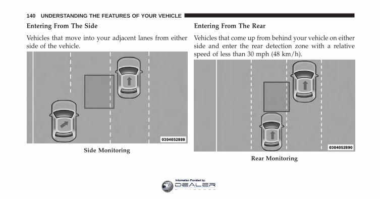
Entering From The Side
Vehicles that move into your adjacent lanes from eitherside of the vehicle.
Entering From The Rear
Vehicles that come up from behind your vehicle on eitherside and enter the rear detection zone with a relativespeed of less than 30 mph (48 km/h).
Side MonitoringRear Monitoring
140 UNDERSTANDING THE FEATURES OF YOUR VEHICLE
Information Provided by:
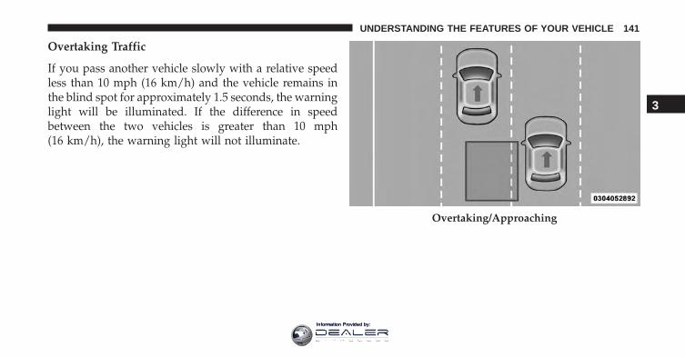
Overtaking Traffic
If you pass another vehicle slowly with a relative speedless than 10 mph (16 km/h) and the vehicle remains inthe blind spot for approximately 1.5 seconds, the warninglight will be illuminated. If the difference in speedbetween the two vehicles is greater than 10 mph(16 km/h), the warning light will not illuminate.
Overtaking/Approaching
3
UNDERSTANDING THE FEATURES OF YOUR VEHICLE 141
Information Provided by:
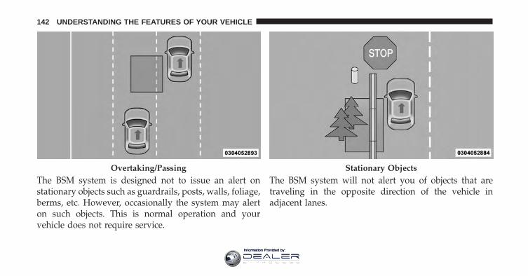
The BSM system is designed not to issue an alert onstationary objects such as guardrails, posts, walls, foliage,berms, etc. However, occasionally the system may alerton such objects. This is normal operation and yourvehicle does not require service.
The BSM system will not alert you of objects that aretraveling in the opposite direction of the vehicle inadjacent lanes.
Overtaking/Passing Stationary Objects
142 UNDERSTANDING THE FEATURES OF YOUR VEHICLE
Information Provided by:
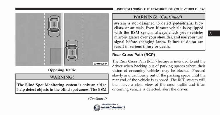
WARNING!
The Blind Spot Monitoring system is only an aid tohelp detect objects in the blind spot zones. The BSM
(Continued)
WARNING! (Continued)system is not designed to detect pedestrians, bicy-clists, or animals. Even if your vehicle is equippedwith the BSM system, always check your vehiclesmirrors, glance over your shoulder, and use your turnsignal before changing lanes. Failure to do so canresult in serious injury or death.
Rear Cross Path (RCP)
The Rear Cross Path (RCP) feature is intended to aid thedriver when backing out of parking spaces where theirvision of oncoming vehicles may be blocked. Proceedslowly and cautiously out of the parking space until therear end of the vehicle is exposed. The RCP system willthen have a clear view of the cross traffic and if anoncoming vehicle is detected, alert the driver.
Opposing Traffic
3
UNDERSTANDING THE FEATURES OF YOUR VEHICLE 143
Information Provided by:
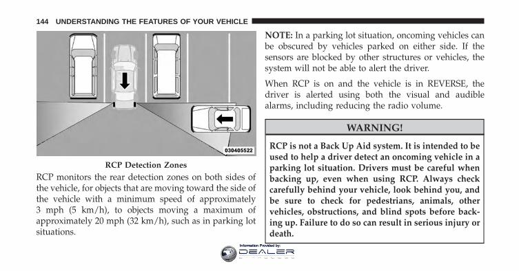
RCP monitors the rear detection zones on both sides ofthe vehicle, for objects that are moving toward the side ofthe vehicle with a minimum speed of approximately3 mph (5 km/h), to objects moving a maximum ofapproximately 20 mph (32 km/h), such as in parking lotsituations.
NOTE: In a parking lot situation, oncoming vehicles canbe obscured by vehicles parked on either side. If thesensors are blocked by other structures or vehicles, thesystem will not be able to alert the driver.
When RCP is on and the vehicle is in REVERSE, thedriver is alerted using both the visual and audiblealarms, including reducing the radio volume.
WARNING!
RCP is not a Back Up Aid system. It is intended to beused to help a driver detect an oncoming vehicle in aparking lot situation. Drivers must be careful whenbacking up, even when using RCP. Always checkcarefully behind your vehicle, look behind you, andbe sure to check for pedestrians, animals, othervehicles, obstructions, and blind spots before back-ing up. Failure to do so can result in serious injury ordeath.
RCP Detection Zones
144 UNDERSTANDING THE FEATURES OF YOUR VEHICLE
Information Provided by:
Modes Of Operation
Three selectable modes of operation are available in theUconnect System. Refer to “Uconnect Settings/CustomerProgrammable Features” in “Understanding Your Instru-ment Panel” for further information.
Blind Spot Alert Lights Only
When operating in Blind Spot Alert mode, the BSMsystem will provide a visual alert in the appropriate sideview mirror based on a detected object. However, whenthe system is operating in Rear Cross Path (RCP) mode,the system will respond with both visual and audiblealerts when a detected object is present. Whenever anaudible alert is requested, the radio is muted.
Blind Spot Alert Lights/Chime
When operating in Blind Spot Alert Lights/Chime mode,the BSM system will provide a visual alert in the appro-priate side view mirror based on a detected object. If the
turn signal is then activated, and it corresponds to analert present on that side of the vehicle, an audible chimewill also be sounded. Whenever a turn signal and de-tected object are present on the same side at the sametime, both the visual and audible alerts will be issued. Inaddition to the audible alert the radio (if on) will also bemuted.
NOTE: Whenever an audible alert is requested by theBSM system, the radio is also muted.
When the system is in RCP, the system shall respond withboth visual and audible alerts when a detected object ispresent. Whenever an audible alert is requested, the radiois also muted. Turn/hazard signal status is ignored; theRCP state always requests the chime.
Blind Spot Alert Off
When the BSM system is turned off there will be no visualor audible alerts from either the BSM or RCP systems.
3
UNDERSTANDING THE FEATURES OF YOUR VEHICLE 145
Information Provided by:
NOTE: The BSM system will store the current operatingmode when the vehicle is shut off. Each time the vehicleis started the previously stored mode will be recalled andused.
General Information
This vehicle has systems that operate on radio frequencythat comply with Part 15 of the Federal CommunicationsCommission (FCC) rules and with Industry CanadaStandards RSS- GEN/210/220/310.
Operation is subject to the following two conditions:
1. The device may not cause harmful interference.
2. The device must accept any interference received,including interference that may cause undesired op-eration of the device.
Changes or modifications to any of these systems byother than an authorized service facility could voidauthorization to use this equipment.
SEATS
Seats are a part of the Occupant Restraint System of thevehicle.
WARNING!
• It is dangerous to ride in a cargo area, inside oroutside of a vehicle. In a collision, people riding inthese areas are more likely to be seriously injuredor killed.
• Do not allow people to ride in any area of yourvehicle that is not equipped with seats and seatbelts. In a collision, people riding in these areas aremore likely to be seriously injured or killed.
• Be sure everyone in your vehicle is in a seat andusing a seat belt properly.
146 UNDERSTANDING THE FEATURES OF YOUR VEHICLE
Information Provided by:
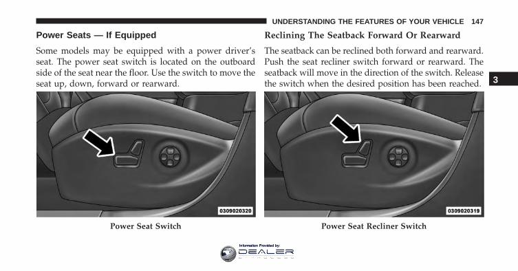
Power Seats — If Equipped
Some models may be equipped with a power driver’sseat. The power seat switch is located on the outboardside of the seat near the floor. Use the switch to move theseat up, down, forward or rearward.
Reclining The Seatback Forward Or Rearward
The seatback can be reclined both forward and rearward.Push the seat recliner switch forward or rearward. Theseatback will move in the direction of the switch. Releasethe switch when the desired position has been reached.
Power Seat Switch Power Seat Recliner Switch
3
UNDERSTANDING THE FEATURES OF YOUR VEHICLE 147
Information Provided by:
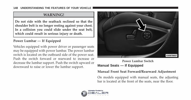
WARNING!
Do not ride with the seatback reclined so that theshoulder belt is no longer resting against your chest.In a collision you could slide under the seat belt,which could result in serious injury or death.
Power Lumbar — If Equipped
Vehicles equipped with power driver or passenger seatsmay be equipped with power lumbar. The power lumbarswitch is located on the outboard side of the power seat.Push the switch forward or rearward to increase ordecrease the lumbar support. Push the switch upward ordownward to raise or lower the lumbar support. Manual Seats — If Equipped
Manual Front Seat Forward/Rearward Adjustment
On models equipped with manual seats, the adjustingbar is located at the front of the seats, near the floor.
Power Lumbar Switch
148 UNDERSTANDING THE FEATURES OF YOUR VEHICLE
Information Provided by:
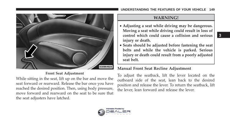
While sitting in the seat, lift up on the bar and move theseat forward or rearward. Release the bar once you havereached the desired position. Then, using body pressure,move forward and rearward on the seat to be sure thatthe seat adjusters have latched.
WARNING!
• Adjusting a seat while driving may be dangerous.Moving a seat while driving could result in loss ofcontrol which could cause a collision and seriousinjury or death.
• Seats should be adjusted before fastening the seatbelts and while the vehicle is parked. Seriousinjury or death could result from a poorly adjustedseat belt.
Manual Front Seat Recline Adjustment
To adjust the seatback, lift the lever located on theoutboard side of the seat, lean back to the desiredposition and release the lever. To return the seatback, liftthe lever, lean forward and release the lever.
Front Seat Adjustment
3
UNDERSTANDING THE FEATURES OF YOUR VEHICLE 149
Information Provided by:
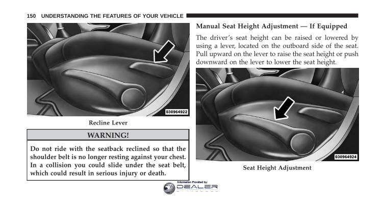
WARNING!
Do not ride with the seatback reclined so that theshoulder belt is no longer resting against your chest.In a collision you could slide under the seat belt,which could result in serious injury or death.
Manual Seat Height Adjustment — If Equipped
The driver’s seat height can be raised or lowered byusing a lever, located on the outboard side of the seat.Pull upward on the lever to raise the seat height or pushdownward on the lever to lower the seat height.
Recline Lever
Seat Height Adjustment
150 UNDERSTANDING THE FEATURES OF YOUR VEHICLE
Information Provided by:
Front Heated Seats — If Equipped
The front heated seats control buttons are located withinthe Uconnect system. You can gain access to the controlbuttons through the climate screen or the controls screen.
• Press the heated seat button once to turn the HIsetting ON.
• Press the heated seat button a second time to turnthe LO setting ON.
• Press the heated seat button a third time to turnthe heating elements OFF.
If the HI-level setting is selected, the system will auto-matically switch to LO-level after approximately 60 min-utes of continuous operation. At that time, the displaywill change from HI to LO, indicating the change. TheLO-level setting will turn OFF automatically after ap-proximately 45 minutes.
NOTE: The engine must be running for the heated seatsto operate.
Vehicles Equipped With Remote Start
On models that are equipped with remote start, theheated seats can be programed to come on during aremote start.
This feature can be programmed through the Uconnectsystem. Refer to “Uconnect Settings” in “UnderstandingYour Instrument Panel” for further information.
WARNING!
• Persons who are unable to feel pain to the skinbecause of advanced age, chronic illness, diabetes,spinal cord injury, medication, alcohol use, exhaus-tion or other physical condition must exercise carewhen using the seat heater. It may cause burns
(Continued)
3
UNDERSTANDING THE FEATURES OF YOUR VEHICLE 151
Information Provided by:
WARNING! (Continued)even at low temperatures, especially if used forlong periods of time.
• Do not place anything on the seat or seatback thatinsulates against heat, such as a blanket or cushion.This may cause the seat heater to overheat. Sittingin a seat that has been overheated could causeserious burns due to the increased surface tempera-ture of the seat.
Front Ventilated Seats — If Equipped
Located in the seat cushion and seat back are fans thatdraw the air from the passenger compartment and moveair through fine perforations in the seat cover to helpkeep the driver and front passenger cooler in higherambient temperatures. The fans operate at two speeds,HI and LO.
The front ventilated seats control buttons are locatedwithin the Uconnect system. You can gain access to thecontrol buttons through the climate screen or the controlsscreen.
• Press the ventilated seat button once to choose HI.
• Press the ventilated seat button a second time tochoose LO.
• Press the ventilated seat button a third time toturn the ventilated seat OFF.
NOTE: The engine must be running for the ventilatedseats to operate.
Vehicles Equipped With Remote Start
On models that are equipped with remote start, theventilated seats can be programed to come on during aremote start.
152 UNDERSTANDING THE FEATURES OF YOUR VEHICLE
Information Provided by:
This feature can be programmed through the Uconnectsystem. Refer to “Uconnect Settings” in “UnderstandingYour Instrument Panel” for further information.
Head Restraints
Head restraints are designed to reduce the risk of injuryby restricting head movement in the event of a rearimpact. Head restraints should be adjusted so that the topof the head restraint is located above the top of your ear.
WARNING!
The head restraints for all occupants must be prop-erly adjusted prior to operating the vehicle or occu-pying a seat. Head restraints should never be ad-justed while the vehicle is in motion. Driving avehicle with the head restraints improperly adjustedor removed could cause serious injury or death in theevent of a collision.
NOTE: Do not reverse the head restraints (making therear of the head restraint face forward) in an attempt togain additional clearance to the back of your head.
Reactive Head Restraints — Front Seats
The front driver and passenger seats are equipped withReactive Head Restraints (RHR). In the event of a rearimpact the RHRs will automatically extend forwardminimizing the gap between the back of the occupant’shead and the RHR.
The RHRs will automatically return to their normalposition following a rear impact. If the RHRs do notreturn to their normal position see your authorizeddealer immediately.
To raise the head restraint, pull upward on the headrestraint. To lower the head restraint, push the adjust-ment button, located at the base of the head restraint, andpush downward on the head restraint.
3
UNDERSTANDING THE FEATURES OF YOUR VEHICLE 153
Information Provided by:
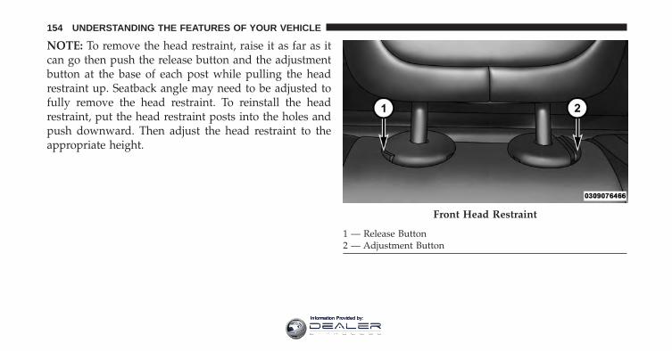
NOTE: To remove the head restraint, raise it as far as itcan go then push the release button and the adjustmentbutton at the base of each post while pulling the headrestraint up. Seatback angle may need to be adjusted tofully remove the head restraint. To reinstall the headrestraint, put the head restraint posts into the holes andpush downward. Then adjust the head restraint to theappropriate height.
Front Head Restraint
1 — Release Button2 — Adjustment Button
154 UNDERSTANDING THE FEATURES OF YOUR VEHICLE
Information Provided by:
WARNING!
• A loose head restraint thrown forward in a colli-sion or hard stop could cause serious injury ordeath to occupants of the vehicle. Always securelystow removed head restraints in a location outsidethe occupant compartment.
• ALL the head restraints MUST be reinstalled in thevehicle to properly protect the occupants. Followthe re-installation instructions above prior to oper-ating the vehicle or occupying a seat.
• Do not place items over the top of the ReactiveHead Restraint, such as coats, seat covers or por-table DVD players. These items may interfere withthe operation of the Reactive Head Restraint in theevent of a collision and could result in seriousinjury or death.
Rear Head Restraints
The rear outboard head restraints have three positionsUp, Mid and Down. The center head restraint has onlytwo positions, Up and Down. When the center seat isbeing occupied the head restraint should be in the raisedposition. When there is no occupant in the center seat thehead restraint can be lowered for maximum visibility forthe driver.
To raise the head restraint, pull upward on the headrestraint. To lower the head restraint, push the adjust-ment button, located at the base of the head restraint, andpush downward on the head restraint.
NOTE: To remove the head restraint, raise it as far as itcan go then push the release button and the adjustmentbutton at the base of each post while pulling the headrestraint up. To reinstall the head restraint, put the headrestraint posts into the holes and push downward. Thenadjust the head restraint to the appropriate height.
3
UNDERSTANDING THE FEATURES OF YOUR VEHICLE 155
Information Provided by:
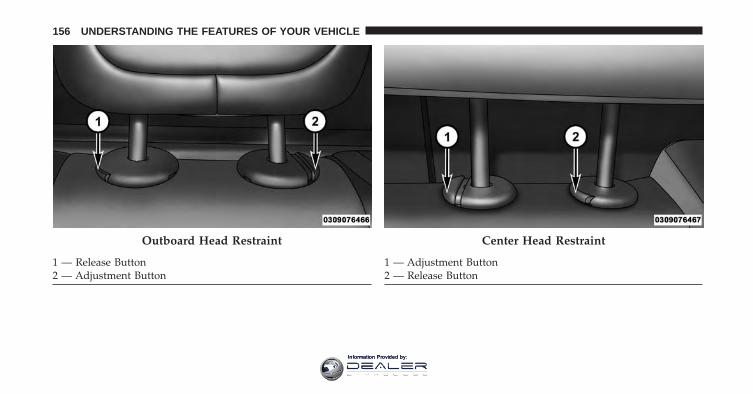
Outboard Head Restraint
1 — Release Button2 — Adjustment Button
Center Head Restraint
1 — Adjustment Button2 — Release Button
156 UNDERSTANDING THE FEATURES OF YOUR VEHICLE
Information Provided by:
WARNING!
ALL the head restraints MUST be reinstalled in thevehicle to properly protect the occupants. Follow there-installation instructions above prior to operatingthe vehicle or occupying a seat.
60/40 Split Folding Rear Seat With Fold-FlatFeature
To provide additional storage area, each rear seat can befolded flat. This allows for extended cargo space and stillmaintains some rear seating room.
NOTE: Prior to folding the rear seat, it may be necessaryto position the front seat to its mid-track position. Also,be sure that the front seats are fully upright and posi-tioned forward. This will allow the rear seat to fold downeasily.
WARNING!
• It is extremely dangerous to ride in a cargo area,inside or outside of a vehicle. In a collision, peopleriding in these areas are more likely to be seriouslyinjured or killed.
• Do not allow people to ride in any area of yourvehicle that is not equipped with seats and seatbelts.
• Be sure everyone in your vehicle is in a seat andusing a seat belt properly.
Rear Seat Forward/Rearward Adjustment — IfEquipped
Lift up on the adjusting bar located at the front of the seatnear the floor and release it when the seat is at the desiredposition. Then, using body pressure, move forward andrearward on the seat to be sure that the seat adjustershave latched.
3
UNDERSTANDING THE FEATURES OF YOUR VEHICLE 157
Information Provided by:
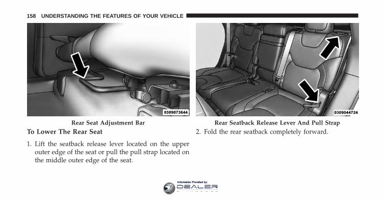
To Lower The Rear Seat
1. Lift the seatback release lever located on the upperouter edge of the seat or pull the pull strap located onthe middle outer edge of the seat.
2. Fold the rear seatback completely forward.Rear Seat Adjustment Bar Rear Seatback Release Lever And Pull Strap
158 UNDERSTANDING THE FEATURES OF YOUR VEHICLE
Information Provided by:
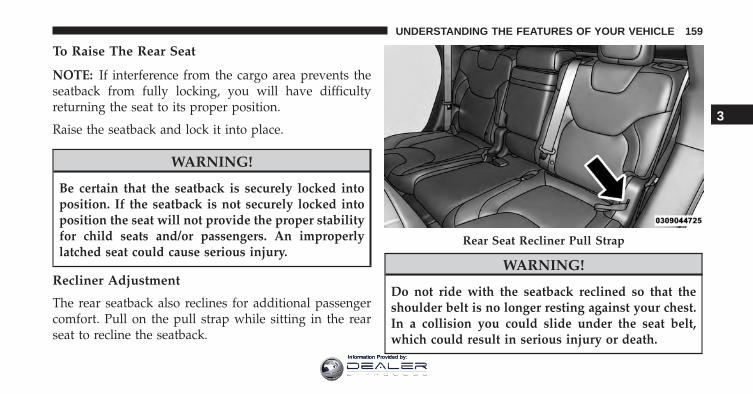
To Raise The Rear Seat
NOTE: If interference from the cargo area prevents theseatback from fully locking, you will have difficultyreturning the seat to its proper position.
Raise the seatback and lock it into place.
WARNING!
Be certain that the seatback is securely locked intoposition. If the seatback is not securely locked intoposition the seat will not provide the proper stabilityfor child seats and/or passengers. An improperlylatched seat could cause serious injury.
Recliner Adjustment
The rear seatback also reclines for additional passengercomfort. Pull on the pull strap while sitting in the rearseat to recline the seatback.
WARNING!
Do not ride with the seatback reclined so that theshoulder belt is no longer resting against your chest.In a collision you could slide under the seat belt,which could result in serious injury or death.
Rear Seat Recliner Pull Strap
3
UNDERSTANDING THE FEATURES OF YOUR VEHICLE 159
Information Provided by:
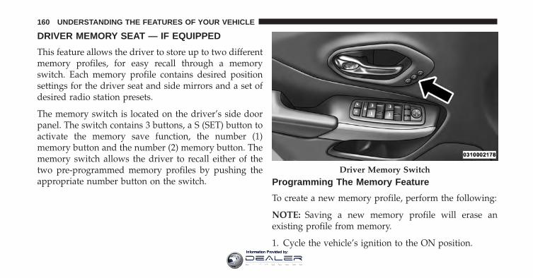
DRIVER MEMORY SEAT — IF EQUIPPED
This feature allows the driver to store up to two differentmemory profiles, for easy recall through a memoryswitch. Each memory profile contains desired positionsettings for the driver seat and side mirrors and a set ofdesired radio station presets.
The memory switch is located on the driver’s side doorpanel. The switch contains 3 buttons, a S (SET) button toactivate the memory save function, the number (1)memory button and the number (2) memory button. Thememory switch allows the driver to recall either of thetwo pre-programmed memory profiles by pushing theappropriate number button on the switch. Programming The Memory Feature
To create a new memory profile, perform the following:
NOTE: Saving a new memory profile will erase anexisting profile from memory.
1. Cycle the vehicle’s ignition to the ON position.
Driver Memory Switch
160 UNDERSTANDING THE FEATURES OF YOUR VEHICLE
Information Provided by:
2. Adjust all memory profile settings to desired prefer-ences (i.e., seat, side mirror and radio station presets).
3. Push and release the SET button on the memoryswitch, then push the number (1) button within fiveseconds. The Electronic Vehicle Information Center(EVIC) or Driver Information Display (DID), willdisplay which memory position is being set.
If desired, a second memory profile can be stored intomemory as follows:
1. Cycle the vehicle’s ignition to the ON position.
2. Adjust all memory profile settings to desired prefer-ences (i.e., seat, side mirror and radio station presets).
3. Push and release the SET button on the memoryswitch, then push the number (2) button within fiveseconds. The EVIC/DID will display which memoryposition is being set.
NOTE:
• Memory profiles can be set without the vehicle inPARK, but the vehicle must be in PARK to recall amemory profile.
• To set a memory profile to your RKE transmitter, referto “Linking And Unlinking The Remote Keyless EntryTransmitter To Memory” in this section.
Linking And Unlinking The Remote Keyless EntryTransmitter To Memory
Your Remote Keyless Entry (RKE) transmitters can beprogrammed to recall one of two pre-programmedmemory profiles with a push of the UNLOCK button onthe RKE transmitter.
3
UNDERSTANDING THE FEATURES OF YOUR VEHICLE 161
Information Provided by:
NOTE: Before programming your RKE transmitters youmust select the “Memory To FOB” feature through theUconnect system screen. Refer to “Uconnect Settings” in“Understanding Your Instrument Panel” for further in-formation.
To program your RKE transmitters, perform the follow-ing:
1. Cycle the vehicle’s ignition to the OFF position.
2. Select the desired memory profile 1 or 2.
NOTE: If a memory profile has not already been set, referto �Programming The Memory Feature� in this section forinstructions on how to set a memory profile.
3. Push and release the SET button on the memoryswitch, then within five seconds push and release thebutton labeled 1 or 2 accordingly. “Memory ProfileSet” (1 or 2) will display in the EVIC/DID.
4. Push and release the LOCK button on the RKE trans-mitter within 10 seconds.
NOTE: Your RKE transmitters can be unlinked to yourmemory settings by pushing the SET (S) button, followedby pushing the UNLOCK button on the RKE transmitterwithin 10 seconds.
Memory Position Recall
NOTE: The vehicle must be in PARK to recall memorypositions. If a recall is attempted when the vehicle is notin PARK, a message will display in the EVIC/DID.
To recall the memory settings for driver one, pushMEMORY button number 1 or the UNLOCK button onthe RKE transmitter linked to memory position 1.
To recall the memory settings for driver two, pushMEMORY button number 2 or the UNLOCK button onthe RKE transmitter linked to memory position 2.
162 UNDERSTANDING THE FEATURES OF YOUR VEHICLE
Information Provided by:

A recall can be cancelled by pushing any of the MEMORYbuttons (S, 1, or 2) during a recall. When a recall iscancelled, the driver seat will stop moving. A delay ofone second will occur before another recall can beselected.
Easy Entry/Exit Seat
This feature provides automatic driver seat positioning toenhance driver mobility when entering and exiting thevehicle.
The distance the driver seat moves depends on whereyou have the driver seat positioned when you cycle thevehicle’s ignition to the OFF position.
• When you cycle the vehicle’s ignition to the OFFposition, the driver seat will move about 2.4 in (60mm) rearward if the driver seat position is greater thanor equal to 2.7 in (67.7 mm) forward of the rear stop.
The seat will return to its previously set position whenyou cycle the vehicle’s ignition to the ACC or RUNposition.
• The Easy Entry/Easy Exit feature is disabled when thedriver seat position is less than 0.9 in (22.7 mm)forward of the rear stop. At this position, there is nobenefit to the driver by moving the seat for Easy Exitor Easy Entry.
Each stored memory setting will have an associated EasyEntry and Easy Exit position.
NOTE: The Easy Entry/Exit feature is not enabled whenthe vehicle is delivered from the factory. The EasyEntry/Exit feature is enabled (or later disabled) throughthe programmable features in the Uconnect system. Referto “Uconnect Settings/Customer Programmable Fea-tures” in “Understanding Your Instrument Panel” forfurther information.
3
UNDERSTANDING THE FEATURES OF YOUR VEHICLE 163
Information Provided by:
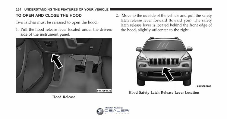
TO OPEN AND CLOSE THE HOOD
Two latches must be released to open the hood.
1. Pull the hood release lever located under the driversside of the instrument panel.
2. Move to the outside of the vehicle and pull the safetylatch release lever forward (toward you). The safetylatch release lever is located behind the front edge ofthe hood, slightly off-center to the right.
Hood ReleaseHood Safety Latch Release Lever Location
164 UNDERSTANDING THE FEATURES OF YOUR VEHICLE
Information Provided by:
CAUTION!
To prevent possible damage, do not slam the hood toclose it. Lower the hood until it is open approxi-mately 6 inches (15 cm), and then drop it. This shouldsecure both latches. Never drive your vehicle unlessthe hood is fully closed, with both latches engaged.
WARNING!
Be sure the hood is fully latched before driving yourvehicle. If the hood is not fully latched, it could openwhen the vehicle is in motion and block your vision.Failure to follow this warning could result in seriousinjury or death.
LIGHTS
Headlight Switch
The headlight switch is located on the left side ofthe instrument panel. This switch controls theoperation of the headlights, parking lights, auto-
matic headlights — if equipped, instrument panel lights,instrument panel light dimming, interior lights and foglights — if equipped.
3
UNDERSTANDING THE FEATURES OF YOUR VEHICLE 165
Information Provided by:
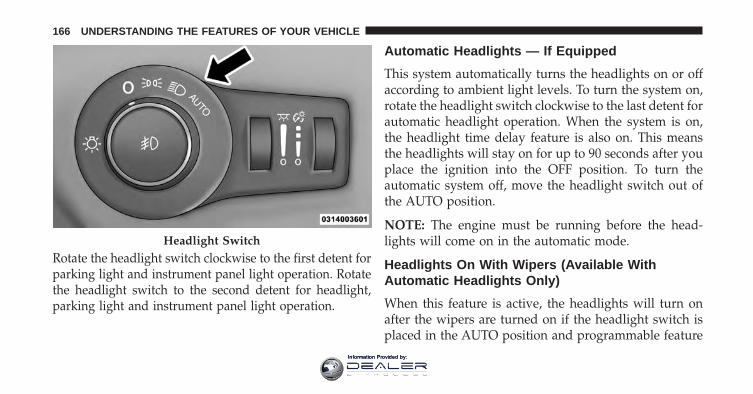
Rotate the headlight switch clockwise to the first detent forparking light and instrument panel light operation. Rotatethe headlight switch to the second detent for headlight,parking light and instrument panel light operation.
Automatic Headlights — If Equipped
This system automatically turns the headlights on or offaccording to ambient light levels. To turn the system on,rotate the headlight switch clockwise to the last detent forautomatic headlight operation. When the system is on,the headlight time delay feature is also on. This meansthe headlights will stay on for up to 90 seconds after youplace the ignition into the OFF position. To turn theautomatic system off, move the headlight switch out ofthe AUTO position.
NOTE: The engine must be running before the head-lights will come on in the automatic mode.
Headlights On With Wipers (Available WithAutomatic Headlights Only)
When this feature is active, the headlights will turn onafter the wipers are turned on if the headlight switch isplaced in the AUTO position and programmable feature
Headlight Switch
166 UNDERSTANDING THE FEATURES OF YOUR VEHICLE
Information Provided by:
is set to ON. In addition, the headlights will turn offwhen the wipers are turned off if they were turned on bythis feature.
NOTE: The Headlights On with Wipers feature can beturned on or off using the Uconnect System. Refer to“Uconnect Settings/Customer Programmable Features”in “Understanding Your Instrument Panel” for furtherinformation.
Headlight Time Delay
This feature provides the safety of headlight illuminationfor up to 90 seconds (programmable) when leaving yourvehicle in an unlit area.
To activate the delay feature, place the ignition in the OFFposition while the headlights are still on. Then, turn offthe headlights within 45 seconds. The delay intervalbegins when the headlight switch is turned off.
If you turn the headlights or parking lights on, or placethe ignition in ACC or RUN, the system will cancel thedelay.
If you turn the headlights off before the ignition, they willturn off in the normal manner.
NOTE:
• The lights must be turned off within 45 seconds ofplacing the ignition in the OFF position to activate thisfeature.
• The headlight delay time is programmable using theUconnect System, refer to “Uconnect Settings” in“Understanding Your Instrument Panel” for furtherinformation.
3
UNDERSTANDING THE FEATURES OF YOUR VEHICLE 167
Information Provided by:
Automatic High Beam Headlamp Control — IfEquipped
The Automatic High Beam Headlamp Control systemprovides increased forward lighting at night by automat-ing high beam control through the use of a digital cameramounted on the inside rearview mirror. This cameradetects vehicle specific light and automatically switchesfrom high beams to low beams until the approachingvehicle is out of view.
NOTE:
• The Automatic High Beam Headlamp Control can beturned on or off using the Uconnect System. Refer to“Uconnect Settings” in “Understanding Your Instru-ment Panel” for further information.
• Broken, muddy, or obstructed headlights and taillightsof vehicles in the field of view will cause headlights toremain on longer (closer to the vehicle). Also, dirt, film,
and other obstructions on the windshield or cameralens will cause the system to function improperly.
• To opt out of the Advanced Auto High-Beam Sensitiv-ity Control (default) and enter Reduced High-BeamSensitivity Control (not recommended), toggle high-beam lever 6 full on/off cycles within 10 seconds ofignition ON. System will return to default setting uponignition off.
Daytime Running Lights (DRL) — If Equipped
The Daytime Running Lights will turn On when theengine is started and remain On unless the headlampsare turned ON, the parking brake is applied, or theengine is shut Off.
168 UNDERSTANDING THE FEATURES OF YOUR VEHICLE
Information Provided by:

NOTE: If allowed by law in the country in which thevehicle was purchased the Daytime Running Lights canbe turned on and off using the Uconnect System, refer to“Uconnect Settings” in “Understanding Your InstrumentPanel” for further information.
Lights-On Reminder
If the headlights or parking lights are on after the ignitionis in the OFF position, a chime will sound to alert thedriver when the driver’s door is opened.
Fog Lights — If Equipped
The front fog light switch is built into the headlightswitch. To activate the front fog lights, turn on the parking
lights or the low beam headlights and push theheadlight switch. To turn off the front fog lights, eitherpush the headlight switch a second time or turn off theheadlight switch.
Fog Light Switch
3
UNDERSTANDING THE FEATURES OF YOUR VEHICLE 169
Information Provided by:
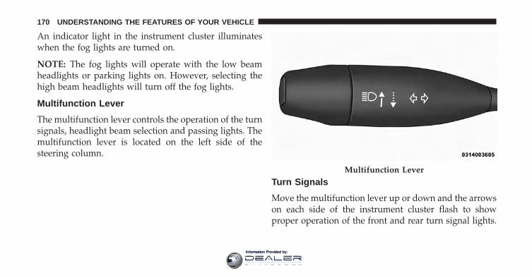
An indicator light in the instrument cluster illuminateswhen the fog lights are turned on.
NOTE: The fog lights will operate with the low beamheadlights or parking lights on. However, selecting thehigh beam headlights will turn off the fog lights.
Multifunction Lever
The multifunction lever controls the operation of the turnsignals, headlight beam selection and passing lights. Themultifunction lever is located on the left side of thesteering column.
Turn Signals
Move the multifunction lever up or down and the arrowson each side of the instrument cluster flash to showproper operation of the front and rear turn signal lights.
Multifunction Lever
170 UNDERSTANDING THE FEATURES OF YOUR VEHICLE
Information Provided by:
NOTE:
• If either light remains on and does not flash, or there isa very fast flash rate, check for a defective outside lightbulb. If an indicator fails to light when the lever ismoved, it would suggest that the indicator bulb isdefective.
• A “Turn Signal On” message will appear in the EVIC/DID and a continuous chime will sound if the vehicleis driven more than 1 mile (1.6 km) with either turnsignal on.
• When the Daytime Running Lights are on and a turnsignal is activated, the Daytime Running Lamp willturn off on the side of the vehicle in which the turnsignal is flashing. The Daytime Running Lamp willturn back on when the turn signal is turned off.
Lane Change Assist
Tap the lever up or down once, without moving beyondthe detent, and the turn signal (right or left) will flashthree times then automatically turn off.
High/Low Beam Switch
Push the multifunction lever away from you to switchthe headlights to high beam. Pull the multifunction levertoward you to switch the headlights back to low beam.
Flash-To-Pass
You can signal another vehicle with your headlights bylightly pulling the multifunction lever toward you. Thiswill turn on the high beams headlights until the lever isreleased.
Front Map/Reading Lights
The front map/reading lights are mounted in the over-head console. Each light can be turned on by pushing a
3
UNDERSTANDING THE FEATURES OF YOUR VEHICLE 171
Information Provided by:
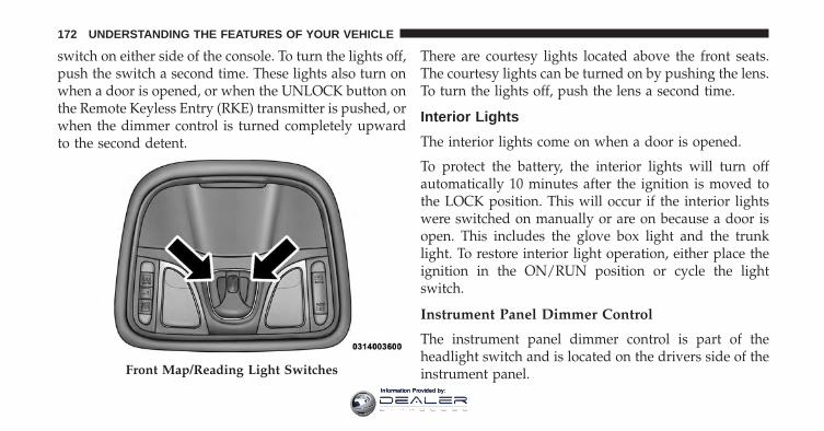
switch on either side of the console. To turn the lights off,push the switch a second time. These lights also turn onwhen a door is opened, or when the UNLOCK button onthe Remote Keyless Entry (RKE) transmitter is pushed, orwhen the dimmer control is turned completely upwardto the second detent.
There are courtesy lights located above the front seats.The courtesy lights can be turned on by pushing the lens.To turn the lights off, push the lens a second time.
Interior Lights
The interior lights come on when a door is opened.
To protect the battery, the interior lights will turn offautomatically 10 minutes after the ignition is moved tothe LOCK position. This will occur if the interior lightswere switched on manually or are on because a door isopen. This includes the glove box light and the trunklight. To restore interior light operation, either place theignition in the ON/RUN position or cycle the lightswitch.
Instrument Panel Dimmer Control
The instrument panel dimmer control is part of theheadlight switch and is located on the drivers side of theinstrument panel.Front Map/Reading Light Switches
172 UNDERSTANDING THE FEATURES OF YOUR VEHICLE
Information Provided by:
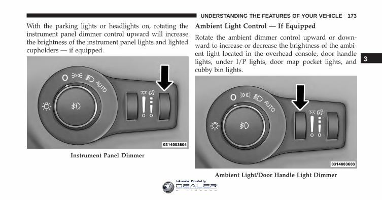
With the parking lights or headlights on, rotating theinstrument panel dimmer control upward will increasethe brightness of the instrument panel lights and lightedcupholders — if equipped.
Ambient Light Control — If Equipped
Rotate the ambient dimmer control upward or down-ward to increase or decrease the brightness of the ambi-ent light located in the overhead console, door handlelights, under I/P lights, door map pocket lights, andcubby bin lights.
Instrument Panel Dimmer
Ambient Light/Door Handle Light Dimmer
3
UNDERSTANDING THE FEATURES OF YOUR VEHICLE 173
Information Provided by:
Dome Light Position
Rotate the instrument panel dimmer control completelyupward to the second detent to turn on the interior lights.The interior lights will remain on when the instrumentpanel dimmer control is in this position.
Interior Light Defeat (OFF)
Rotate the instrument panel dimmer control to the ex-treme bottom OFF position. The interior lights willremain off when the doors are open.
Parade Mode (Daytime Brightness Feature)
Rotate the instrument panel dimmer control upward tothe first detent. This feature brightens all text displayssuch as the odometer, Electronic Vehicle InformationCenter (EVIC) or Driver Information Display (DID), andradio when the position lights or headlights are on.
Battery Saver Feature
To protect the battery, the interior lights will turn offautomatically 10 minutes after the ignition switch ismoved to the LOCK position. This will occur if theinterior lights were switched on manually or are onbecause a door is open.
WINDSHIELD WIPERS AND WASHERS
The windshield wiper/washer controls are located on thewindshield wiper/washer lever on the right side of thesteering column. The front wipers are operated by rotatinga switch, located on the end of the lever. For information onthe rear wiper/washer, refer to “Rear Window Features” in“Understanding The Features Of Your Vehicle”.
174 UNDERSTANDING THE FEATURES OF YOUR VEHICLE
Information Provided by:
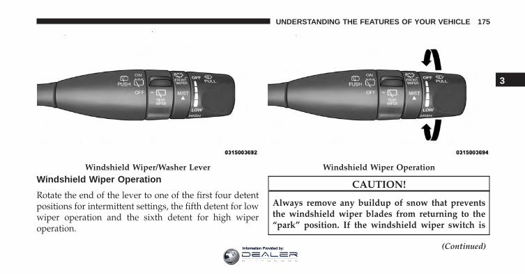
Windshield Wiper Operation
Rotate the end of the lever to one of the first four detentpositions for intermittent settings, the fifth detent for lowwiper operation and the sixth detent for high wiperoperation.
CAUTION!
Always remove any buildup of snow that preventsthe windshield wiper blades from returning to the“park” position. If the windshield wiper switch is
(Continued)
Windshield Wiper/Washer Lever Windshield Wiper Operation
3
UNDERSTANDING THE FEATURES OF YOUR VEHICLE 175
Information Provided by:
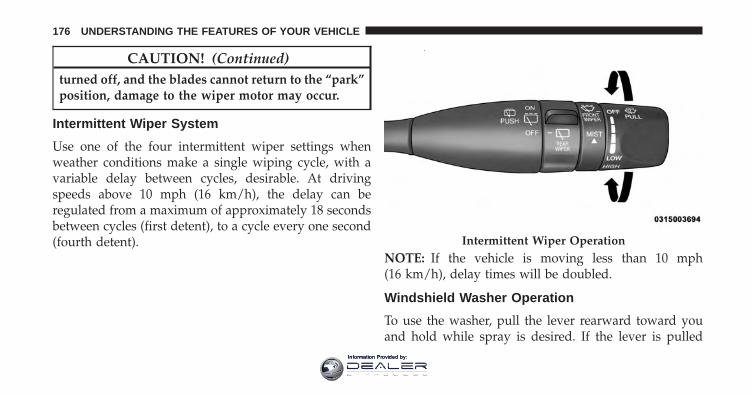
CAUTION! (Continued)turned off, and the blades cannot return to the “park”position, damage to the wiper motor may occur.
Intermittent Wiper System
Use one of the four intermittent wiper settings whenweather conditions make a single wiping cycle, with avariable delay between cycles, desirable. At drivingspeeds above 10 mph (16 km/h), the delay can beregulated from a maximum of approximately 18 secondsbetween cycles (first detent), to a cycle every one second(fourth detent).
NOTE: If the vehicle is moving less than 10 mph(16 km/h), delay times will be doubled.
Windshield Washer Operation
To use the washer, pull the lever rearward toward youand hold while spray is desired. If the lever is pulled
Intermittent Wiper Operation
176 UNDERSTANDING THE FEATURES OF YOUR VEHICLE
Information Provided by:
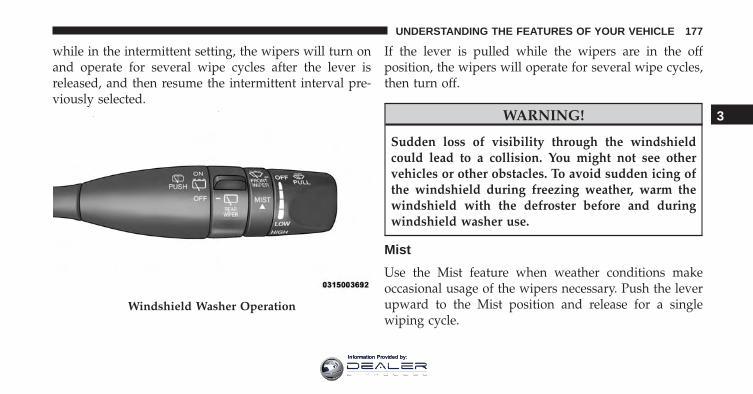
while in the intermittent setting, the wipers will turn onand operate for several wipe cycles after the lever isreleased, and then resume the intermittent interval pre-viously selected.
If the lever is pulled while the wipers are in the offposition, the wipers will operate for several wipe cycles,then turn off.
WARNING!
Sudden loss of visibility through the windshieldcould lead to a collision. You might not see othervehicles or other obstacles. To avoid sudden icing ofthe windshield during freezing weather, warm thewindshield with the defroster before and duringwindshield washer use.
Mist
Use the Mist feature when weather conditions makeoccasional usage of the wipers necessary. Push the leverupward to the Mist position and release for a singlewiping cycle.
Windshield Washer Operation
3
UNDERSTANDING THE FEATURES OF YOUR VEHICLE 177
Information Provided by:
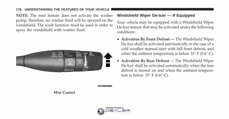
NOTE: The mist feature does not activate the washerpump; therefore, no washer fluid will be sprayed on thewindshield. The wash function must be used in order tospray the windshield with washer fluid.
Windshield Wiper De-Icer — If Equipped
Your vehicle may be equipped with a Windshield WiperDe-Icer feature that may be activated under the followingconditions:
• Activation By Front Defrost — The Windshield WiperDe-Icer shall be activated automatically in the case of acold weather manual start with full front defrost, andwhen the ambient temperature is below 33° F (0.6° C).
• Activation By Rear Defrost — The Windshield WiperDe-Icer shall be activated automatically when the reardefrost is turned on and when the ambient tempera-ture is below 33° F (0.6° C).
Mist Control
178 UNDERSTANDING THE FEATURES OF YOUR VEHICLE
Information Provided by:

• Activation By Remote Start Operation — When re-mote start is active and the outside ambient tempera-ture is less than 33° F (0.6° C), the Windshield WiperDe-Icer shall be enabled. On exiting remote startresume previous operation except, if the WindshieldWiper De-Icer timer and operation shall continue.
Rain Sensing Wipers — If Equipped
This feature senses moisture on the windshield andautomatically activates the wipers for the driver. Thefeature is especially useful for road splash or oversprayfrom the windshield washers of the vehicle ahead. Rotatethe end of the multifunction lever to one of four settingsto activate this feature.
The sensitivity of the system can be adjusted with themultifunction lever. Wiper delay position one is the leastsensitive, and wiper delay position four is the mostsensitive. Setting three should be used for normal rainconditions. Settings one and two can be used if the driver
desires less wiper sensitivity. Setting four can be used ifthe driver desires more sensitivity. Place the wiper switchin the OFF position when not using the system.
NOTE:
• The Rain Sensing feature will not operate when thewiper switch is in the low or high-speed position.
• The Rain Sensing feature may not function properlywhen ice, or dried salt water is present on the wind-shield.
• Use of Rain-X or products containing wax or siliconemay reduce Rain Sensing performance.
• The Rain Sensing feature can be turned on and offusing the Uconnect System, refer to “Uconnect Set-tings” in “Understanding Your Instrument Panel” forfurther information.
3
UNDERSTANDING THE FEATURES OF YOUR VEHICLE 179
Information Provided by:
The Rain Sensing system has protection features for thewiper blades and arms, and will not operate under thefollowing conditions:
• Low Ambient Temperature — When the ignition isfirst turned ON, the Rain Sensing system will notoperate until the wiper switch is moved, vehicle speedis greater than 0 mph (0 km/h), or the outside tem-perature is greater than 32°F (0°C).
• Transmission In NEUTRAL Position — When theignition is ON, and the automatic transmission is inthe NEUTRAL position, the Rain Sensing system willnot operate until the wiper switch is moved, vehiclespeed is greater than 3 mph (5 km/h), or the shiftlever/gear selector is moved out of the NEUTRALposition.
Remote Start Mode Inhibit — On vehicles equippedwith Remote Starting system, Rain Sensing wipers arenot operational when the vehicle is in the remote startmode. Once the operator is in the vehicle and has placedthe ignition switch in the RUN position, rain sensingwiper operation can resume, if it has been selected, andno other inhibit conditions (mentioned previously) exist.
TILT/TELESCOPING STEERING COLUMN
This feature allows you to tilt the steering columnupward or downward. It also allows you to lengthen orshorten the steering column. The tilt/telescoping lever islocated below the steering wheel at the end of thesteering column.
180 UNDERSTANDING THE FEATURES OF YOUR VEHICLE
Information Provided by:
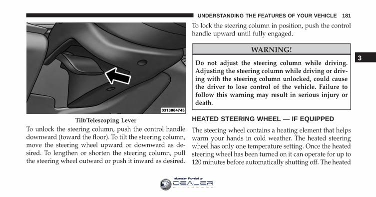
To unlock the steering column, push the control handledownward (toward the floor). To tilt the steering column,move the steering wheel upward or downward as de-sired. To lengthen or shorten the steering column, pullthe steering wheel outward or push it inward as desired.
To lock the steering column in position, push the controlhandle upward until fully engaged.
WARNING!
Do not adjust the steering column while driving.Adjusting the steering column while driving or driv-ing with the steering column unlocked, could causethe driver to lose control of the vehicle. Failure tofollow this warning may result in serious injury ordeath.
HEATED STEERING WHEEL — IF EQUIPPED
The steering wheel contains a heating element that helpswarm your hands in cold weather. The heated steeringwheel has only one temperature setting. Once the heatedsteering wheel has been turned on it can operate for up to120 minutes before automatically shutting off. The heated
Tilt/Telescoping Lever
3
UNDERSTANDING THE FEATURES OF YOUR VEHICLE 181
Information Provided by:
steering wheel can shut off early or may not turn onwhen the steering wheel is already warm.
The heated steering wheel control button is locatedwithin the Uconnect system. You can gain access to thecontrol button through the climate screen or the controlsscreen.
• Press the heated steering wheel button once toturn the heating element ON.
• Press the heated steering wheel button a secondtime to turn the heating element OFF.
NOTE: The engine must be running for the heatedsteering wheel to operate.
Vehicles Equipped With Remote Start
On models that are equipped with remote start, theheated steering wheel can be programmed to come onduring a remote start through the Uconnect system. Refer
to “Uconnect Settings” in “Understanding Your Instru-ment Panel” for further information.
WARNING!
• Persons who are unable to feel pain to the skinbecause of advanced age, chronic illness, diabetes,spinal cord injury, medication, alcohol use, exhaus-tion, or other physical conditions must exercisecare when using the steering wheel heater. It maycause burns even at low temperatures, especially ifused for long periods.
• Do not place anything on the steering wheel thatinsulates against heat, such as a blanket or steeringwheel covers of any type and material. This maycause the steering wheel heater to overheat.
182 UNDERSTANDING THE FEATURES OF YOUR VEHICLE
Information Provided by:
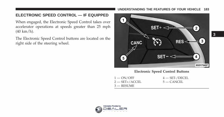
ELECTRONIC SPEED CONTROL — IF EQUIPPED
When engaged, the Electronic Speed Control takes overaccelerator operations at speeds greater than 25 mph(40 km/h).
The Electronic Speed Control buttons are located on theright side of the steering wheel.
Electronic Speed Control Buttons
1 — ON/OFF 4 — SET-/DECEL2 — SET+/ACCEL 5 — CANCEL3 — RESUME
3
UNDERSTANDING THE FEATURES OF YOUR VEHICLE 183
Information Provided by:
NOTE: In order to ensure proper operation, the Elec-tronic Speed Control System has been designed to shutdown if multiple Speed Control functions are operated atthe same time. If this occurs, the Electronic Speed ControlSystem can be reactivated by pushing the ElectronicSpeed Control ON/OFF button and resetting the desiredvehicle set speed.
To Activate
Push the ON/OFF button to activate the electronic speedcontrol. The Cruise Indicator Light in the ElectronicVehicle Information Center (EVIC) or Driver InformationDisplay (DID) will illuminate. To turn the system off,push the ON/OFF button a second time. The CruiseIndicator Light will turn off. The system should beturned off when not in use.
WARNING!
Leaving the Electronic Speed Control system onwhen not in use is dangerous. You could accidentallyset the system or cause it to go faster than you want.You could lose control and have an accident. Alwaysleave the system OFF when you are not using it.
To Set A Desired Speed
Turn the Electronic Speed Control ON.
NOTE: The vehicle should be traveling at a steady speedand on level ground before pushing the SET (+) or SET (-)button.
When the vehicle has reached the desired speed, push theSET (+) or SET (-) button and release. Release theaccelerator and the vehicle will operate at the selectedspeed.
184 UNDERSTANDING THE FEATURES OF YOUR VEHICLE
Information Provided by:
To Deactivate
A soft tap on the brake pedal, pushing the CANCELbutton, or normal brake pressure while slowing thevehicle will deactivate the Electronic Speed Control with-out erasing the set speed from memory.
Pushing the ON/OFF button or turning the ignitionswitch OFF erases the set speed from memory.
To Resume Speed
To resume a previously set speed, push the RES buttonand release. Resume can be used at any speed above20 mph (32 km/h).
To Vary The Speed Setting
To Increase Speed
When the Electronic Speed Control is set, you can in-crease speed by pushing the SET + button.
The drivers preferred units can be selected through theinstrument panel settings if equipped. Refer to “Under-standing Your Instrument Panel” for more information.The speed increment shown is dependant on the chosenspeed unit of U.S. (mph) or Metric (km/h):
U.S. Speed (mph)
• Pushing the SET + button once will result in a 1 mphincrease in set speed. Each subsequent tap of thebutton results in an increase of 1 mph.
• If the button is continually pushed, the set speed willcontinue to increase until the button is released, thenthe new set speed will be established.
Metric Speed (km/h)
• Pushing the SET + button once will result in a 1 km/hincrease in set speed. Each subsequent tap of thebutton results in an increase of 1 km/h.
3
UNDERSTANDING THE FEATURES OF YOUR VEHICLE 185
Information Provided by:
• If the button is continually pushed, the set speed willcontinue to increase until the button is released, thenthe new set speed will be established.
To Decrease Speed
When the Electronic Speed Control is set, you can de-crease speed by pushing the SET - button.
The drivers preferred units can be selected through theinstrument panel settings if equipped. Refer to “Under-standing Your Instrument Panel” for more information.The speed decrement shown is dependant on the chosenspeed unit of U.S. (mph) or Metric (km/h):
U.S. Speed (mph)
• Pushing the SET - button once will result in a 1 mphdecrease in set speed. Each subsequent tap of thebutton results in a decrease of 1 mph.
• If the button is continually pushed, the set speed willcontinue to decrease until the button is released, thenthe new set speed will be established.
Metric Speed (km/h)
• Pushing the SET - button once will result in a 1 km/hdecrease in set speed. Each subsequent tap of thebutton results in a decrease of 1 km/h.
• If the button is continually pushed, the set speed willcontinue to decrease until the button is released, thenthe new set speed will be established.
To Accelerate For Passing
Press the accelerator as you would normally. When thepedal is released, the vehicle will return to the set speed.
Using Electronic Speed Control On Hills
The transmission may downshift on hills to maintain thevehicle set speed.
186 UNDERSTANDING THE FEATURES OF YOUR VEHICLE
Information Provided by:
NOTE: The Electronic Speed Control system maintainsspeed up and down hills. A slight speed change onmoderate hills is normal.
On steep hills, a greater speed loss or gain may occur soit may be preferable to drive without Electronic SpeedControl.
WARNING!
Electronic Speed Control can be dangerous where thesystem cannot maintain a constant speed. Your ve-hicle could go too fast for the conditions, and youcould lose control and have an accident. Do not useElectronic Speed Control in heavy traffic or on roadsthat are winding, icy, snow-covered or slippery.
ADAPTIVE CRUISE CONTROL (ACC) — IFEQUIPPED
Adaptive Cruise Control (ACC) increases the drivingconvenience provided by cruise control while travelingon highways and major roadways. However, it is not asafety system and not designed to prevent collisions.Electronic Speed Control function performs differently.Please refer to the proper section within this chapter.
ACC will allow you to keep cruise control engaged inlight to moderate traffic conditions without the constantneed to reset your cruise control. ACC utilizes a radarsensor and a forward facing camera designed to detect avehicle directly ahead of you.
NOTE:
• If the sensor does not detect a vehicle ahead of you,ACC will maintain a fixed set speed.
3
UNDERSTANDING THE FEATURES OF YOUR VEHICLE 187
Information Provided by:
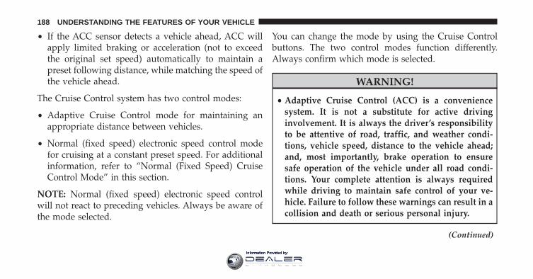
• If the ACC sensor detects a vehicle ahead, ACC willapply limited braking or acceleration (not to exceedthe original set speed) automatically to maintain apreset following distance, while matching the speed ofthe vehicle ahead.
The Cruise Control system has two control modes:
• Adaptive Cruise Control mode for maintaining anappropriate distance between vehicles.
• Normal (fixed speed) electronic speed control modefor cruising at a constant preset speed. For additionalinformation, refer to “Normal (Fixed Speed) CruiseControl Mode” in this section.
NOTE: Normal (fixed speed) electronic speed controlwill not react to preceding vehicles. Always be aware ofthe mode selected.
You can change the mode by using the Cruise Controlbuttons. The two control modes function differently.Always confirm which mode is selected.
WARNING!
• Adaptive Cruise Control (ACC) is a conveniencesystem. It is not a substitute for active drivinginvolvement. It is always the driver’s responsibilityto be attentive of road, traffic, and weather condi-tions, vehicle speed, distance to the vehicle ahead;and, most importantly, brake operation to ensuresafe operation of the vehicle under all road condi-tions. Your complete attention is always requiredwhile driving to maintain safe control of your ve-hicle. Failure to follow these warnings can result in acollision and death or serious personal injury.
(Continued)
188 UNDERSTANDING THE FEATURES OF YOUR VEHICLE
Information Provided by:
WARNING! (Continued)• The ACC system:
• Does not react to pedestrians, oncoming vehicles,and stationary objects (e.g., a stopped vehicle in atraffic jam or a disabled vehicle).
• Cannot take street, traffic, and weather condi-tions into account, and may be limited uponadverse sight distance conditions.
• Does not always fully recognize complex drivingconditions, which can result in wrong or missingdistance warnings.
• Will bring the vehicle to a complete stop whilefollowing a target vehicle and hold the vehiclefor approximately 3 minutes in the stop position.If the target vehicle does not start moving within3 minutes the parking brake will be activated,and the ACC system will be cancelled.
(Continued)
WARNING! (Continued)You should switch off the ACC system:• When driving in fog, heavy rain, heavy snow, sleet,
heavy traffic, and complex driving situations (i.e.,in highway construction zones).
• When entering a turn lane or highway off ramp;when driving on roads that are winding, icy, snow-covered, slippery, or have steep uphill or downhillslopes.
• When towing a trailer up or down steep slopes.• When circumstances do not allow safe driving at a
constant speed.
Adaptive Cruise Control (ACC) Operation
The speed control buttons (located on the right side of thesteering wheel) operates the ACC system.
3
UNDERSTANDING THE FEATURES OF YOUR VEHICLE 189
Information Provided by:
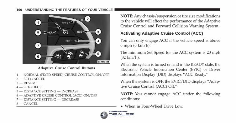
NOTE: Any chassis/suspension or tire size modificationsto the vehicle will effect the performance of the AdaptiveCruise Control and Forward Collision Warning System.
Activating Adaptive Cruise Control (ACC)
You can only engage ACC if the vehicle speed is above0 mph (0 km/h).
The minimum Set Speed for the ACC system is 20 mph(32 km/h).
When the system is turned on and in the READY state, theElectronic Vehicle Information Center (EVIC) or DriverInformation Display (DID) displays “ACC Ready.”
When the system is OFF, the EVIC/DID displays “Adap-tive Cruise Control (ACC) Off.”
NOTE: You cannot engage ACC under the followingconditions:
• When in Four-Wheel Drive Low.
Adaptive Cruise Control Buttons
1 — NORMAL (FIXED SPEED) CRUISE CONTROL ON/OFF2 — SET+/ACCEL3 — RESUME4 — SET-/DECEL5 — DISTANCE SETTING — INCREASE6 — ADAPTIVE CRUISE CONTROL (ACC) ON/OFF7 — DISTANCE SETTING — DECREASE8 — CANCEL
190 UNDERSTANDING THE FEATURES OF YOUR VEHICLE
Information Provided by:
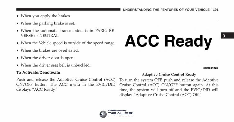
• When you apply the brakes.
• When the parking brake is set.
• When the automatic transmission is in PARK, RE-VERSE or NEUTRAL.
• When the Vehicle speed is outside of the speed range.
• When the brakes are overheated.
• When the driver door is open.
• When the driver seat belt is unbuckled.
To Activate/Deactivate
Push and release the Adaptive Cruise Control (ACC)ON/OFF button. The ACC menu in the EVIC/DIDdisplays “ACC Ready.”
To turn the system OFF, push and release the AdaptiveCruise Control (ACC) ON/OFF button again. At thistime, the system will turn off and the EVIC/DID willdisplay “Adaptive Cruise Control (ACC) Off.”
Adaptive Cruise Control Ready
3
UNDERSTANDING THE FEATURES OF YOUR VEHICLE 191
Information Provided by:
WARNING!
Leaving the Adaptive Cruise Control (ACC) system onwhen not in use is dangerous. You could accidentallyset the system or cause it to go faster than you want.
(Continued)
WARNING! (Continued)You could lose control and have a collision. Alwaysleave the system off when you are not using it.
To Set A Desired ACC Speed
When the vehicle reaches the speed desired, push theSET + button or the SET - button and release. TheEVIC/DID will display the set speed.
If the system is Set when the vehicle speed is below20 mph (32 km/h), the Set Speed shall be defaulted to20 mph (32 km/h). If the system is Set when the vehiclespeed is above 20 mph (32 km/h), the Set Speed shall bethe current speed of the vehicle.
NOTE: ACC cannot be set if there is a stationary vehiclein front of your vehicle in close proximity.
Adaptive Cruise Control Off
192 UNDERSTANDING THE FEATURES OF YOUR VEHICLE
Information Provided by:
Remove your foot from the accelerator pedal. If you donot, the vehicle may continue to accelerate beyond the setspeed. If this occurs:
• The message “DRIVER OVERRIDE” will display inthe EVIC/DID.
• The system will not be controlling the distance be-tween your vehicle and the vehicle ahead. The vehiclespeed will only be determined by the position of theaccelerator pedal.
To Cancel
The following conditions cancel the system:
• The brake pedal is applied.
• The CANCEL button is pushed.
• An Anti-Lock Brake System (ABS) event occurs.
• The shift lever/gear selector is removed from theDrive position.
• The Electronic Stability Control/Traction Control Sys-tem (ESC/TCS) activates.
• The vehicle parking brake is applied.
• Driver seatbelt is unbuckled at low speeds.
• Driver door is opened at low speeds.
• A Trailer Sway Control (TSC) event occurs.
• The driver switches ESC to full-off mode.
To Turn Off
The system will turn off and clear the set speed inmemory if:
• The Adaptive Cruise Control (ACC) ON/OFF buttonis pushed.
3
UNDERSTANDING THE FEATURES OF YOUR VEHICLE 193
Information Provided by:
• The Normal (Fixed Speed) Electronic Speed ControlON/OFF button is pushed.
• The ignition is turned OFF.
• You switch to Four-Wheel Drive Low.
To Resume
If there is a set speed in memory push the RES (resume)button and then remove your foot from the acceleratorpedal. The EVIC/DID will display the last set speed.
NOTE:
• If your vehicle stays at standstill for longer than twoseconds, then the driver will either have to push theRES (resume) button, or apply the accelerator pedal toreengage the ACC to the existing Set Speed.
• ACC cannot be resumed if there is a stationary vehiclein-front of your vehicle in close proximity.
WARNING!
The Resume function should only be used if trafficand road conditions permit. Resuming a set speedthat is too high or too low for prevailing traffic androad conditions could cause the vehicle to accelerateor decelerate too sharply for safe operation. Failure tofollow these warnings can result in a collision anddeath or serious personal injury.
To Vary The Speed Setting
To Increase Speed
While ACC is set, you can increase the set speed bypushing the SET + button.
The drivers preferred units can be selected through theinstrument panel settings if equipped. Refer to “ Under-standing Your Instrument Panel” for more information.
194 UNDERSTANDING THE FEATURES OF YOUR VEHICLE
Information Provided by:
The speed increment shown is dependant on the chosenspeed unit of U.S. (mph) or Metric (km/h):
U.S. Speed (mph)
• Pushing the SET + button once will result in a 1 mphincrease in set speed. Each subsequent tap of thebutton results in an increase of 1 mph.
• If the button is continually pushed, the set speed willcontinue to increase in 5 mph increments until thebutton is released. The increase in set speed is reflectedin the EVIC/DID.
Metric Speed (km/h)
• Pushing the SET + button once will result in a 1 km/hincrease in set speed. Each subsequent tap of thebutton results in an increase of 1 km/h.
• If the button is continually pushed, the set speed willcontinue to increase in 10 km/h increments until thebutton is released. The increase in set speed is reflectedin the EVIC/DID.
To Decrease Speed
While ACC is set, the set speed can be decreased bypushing the SET - button.
The drivers preferred units can be selected through theinstrument panel settings if equipped. Refer to “ Under-standing Your Instrument Panel” for more information.The speed decrement shown is dependant on the chosenspeed unit of U.S. (mph) or Metric (km/h):
U.S. Speed (mph)
• Pushing the SET - button once will result in a 1 mphdecrease in set speed. Each subsequent tap of thebutton results in a decrease of 1 mph.
3
UNDERSTANDING THE FEATURES OF YOUR VEHICLE 195
Information Provided by:
• If the button is continually pushed, the set speed willcontinue to decrease in 5 mph decrements until thebutton is released. The decrease in set speed is re-flected in the EVIC/DID.
Metric Speed (km/h)
• Pushing the SET - button once will result in a 1 km/hdecrease in set speed. Each subsequent tap of thebutton results in a decrease of 1 km/h.
• If the button is continually pushed, the set speed willcontinue to decrease in 10 km/h decrements until thebutton is released. The decrease in set speed is re-flected in the EVIC/DID.
NOTE:
• When you override and push the SET + button or SET- buttons, the new Set Speed will be the current speedof the vehicle.
• When you use the SET - button to decelerate, if theengine’s braking power does not slow the vehiclesufficiently to reach the set speed, the brake systemwill automatically slow the vehicle.
• The ACC system decelerates the vehicle to a full stopwhen following a target vehicle. If an ACC host vehiclefollows a target vehicle to a standstill, after twoseconds the driver will either have to push the RES(resume) button, or apply the accelerator pedal toreengage the ACC to the existing Set Speed.
• The ACC system maintains set speed when driving uphill and down hill. However, a slight speed change onmoderate hills is normal. In addition, downshiftingmay occur while climbing uphill or descending down-hill. This is normal operation and necessary to main-tain set speed. When driving up hill and down hill, theACC system will cancel if the braking temperatureexceeds normal range (overheated).
196 UNDERSTANDING THE FEATURES OF YOUR VEHICLE
Information Provided by:
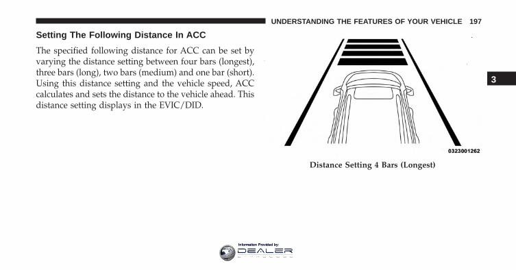
Setting The Following Distance In ACC
The specified following distance for ACC can be set byvarying the distance setting between four bars (longest),three bars (long), two bars (medium) and one bar (short).Using this distance setting and the vehicle speed, ACCcalculates and sets the distance to the vehicle ahead. Thisdistance setting displays in the EVIC/DID.
Distance Setting 4 Bars (Longest)
3
UNDERSTANDING THE FEATURES OF YOUR VEHICLE 197
Information Provided by:
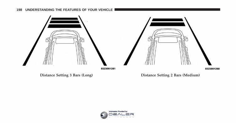
Distance Setting 3 Bars (Long) Distance Setting 2 Bars (Medium)
198 UNDERSTANDING THE FEATURES OF YOUR VEHICLE
Information Provided by:
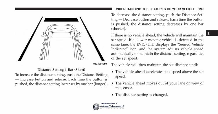
To increase the distance setting, push the Distance Setting— Increase button and release. Each time the button ispushed, the distance setting increases by one bar (longer).
To decrease the distance setting, push the Distance Set-ting — Decrease button and release. Each time the buttonis pushed, the distance setting decreases by one bar(shorter).
If there is no vehicle ahead, the vehicle will maintain theset speed. If a slower moving vehicle is detected in thesame lane, the EVIC/DID displays the “Sensed VehicleIndicator” icon, and the system adjusts vehicle speedautomatically to maintain the distance setting, regardlessof the set speed.
The vehicle will then maintain the set distance until:
• The vehicle ahead accelerates to a speed above the setspeed.
• The vehicle ahead moves out of your lane or view ofthe sensor.
• The distance setting is changed.
Distance Setting 1 Bar (Short)
3
UNDERSTANDING THE FEATURES OF YOUR VEHICLE 199
Information Provided by:
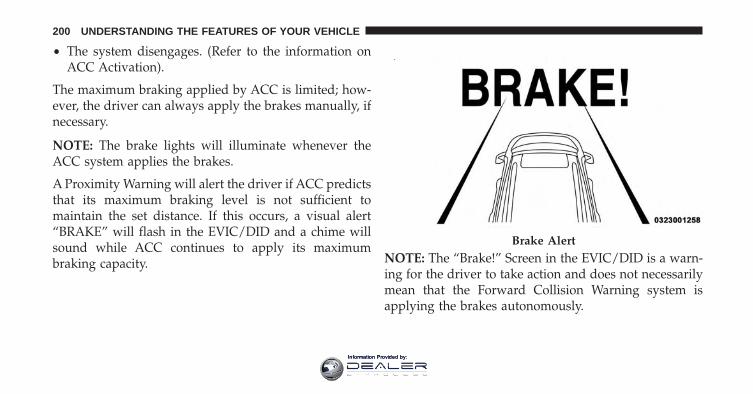
• The system disengages. (Refer to the information onACC Activation).
The maximum braking applied by ACC is limited; how-ever, the driver can always apply the brakes manually, ifnecessary.
NOTE: The brake lights will illuminate whenever theACC system applies the brakes.
A Proximity Warning will alert the driver if ACC predictsthat its maximum braking level is not sufficient tomaintain the set distance. If this occurs, a visual alert“BRAKE” will flash in the EVIC/DID and a chime willsound while ACC continues to apply its maximumbraking capacity. NOTE: The “Brake!” Screen in the EVIC/DID is a warn-
ing for the driver to take action and does not necessarilymean that the Forward Collision Warning system isapplying the brakes autonomously.
Brake Alert
200 UNDERSTANDING THE FEATURES OF YOUR VEHICLE
Information Provided by:
Overtake Aid
When driving with ACC engaged and following a ve-hicle, the system will provide an additional accelerationup to the ACC set speed to assist in passing the vehicle.This additional acceleration is triggered when the driverutilizes the left turn signal and will only be active whenpassing on the left hand side.
ACC Operation At Stop
In the event that the ACC system brings your vehicle toa standstill while following a target vehicle, if the targetvehicle starts moving within two seconds of your vehiclecoming to a standstill, your vehicle will resume motionwithout the need for any driver action.
If the target vehicle does not start moving within twoseconds of your vehicle coming to a standstill, the driverwill either have to push the RES (resume) button, orapply the accelerator pedal to reengage the ACC to theexisting Set Speed.
NOTE: After the ACC system holds your vehicle at astandstill for approximately 3 consecutive minutes, theparking brake will be activated, and the ACC system willbe cancelled.
While ACC is holding your vehicle at a standstill, if thedriver seatbelt is unbuckled or the driver door is opened,the parking brake will be activated, and the ACC systemwill be cancelled.
WARNING!
When the ACC system is resumed, the driver mustensure that there are no pedestrians, vehicles orobjects in the path of the vehicle. Failure to followthese warnings can result in a collision and death orserious personal injury.
3
UNDERSTANDING THE FEATURES OF YOUR VEHICLE 201
Information Provided by:
Adaptive Cruise Control (ACC) Menu
The EVIC/DID displays the current ACC system set-tings. The EVIC/DID is located in the center of theinstrument cluster. The information it displays dependson ACC system status.
Push the ADAPTIVE CRUISE CONTROL (ACC) ON/OFF button (located on the steering wheel) until one ofthe following displays in the EVIC/DID:
Adaptive Cruise Control Off
When ACC is deactivated, the display will read “Adap-tive Cruise Control Off.”
Adaptive Cruise Control Ready
When ACC is activated but the vehicle speed setting hasnot been selected, the display will read “Adaptive CruiseControl Ready.”
Push the SET + or the SET- button (located on the steeringwheel) and the following will display in the EVIC/DID:
ACC SET
When ACC is set, the set speed will display in theinstrument cluster.
The ACC screen may display once again if any ACCactivity occurs, which may include any of the following:
• System Cancel
• Driver Override
• System Off
• ACC Proximity Warning
• ACC Unavailable Warning
• The EVIC/DID will return to the last display selectedafter five seconds of no ACC display activity
202 UNDERSTANDING THE FEATURES OF YOUR VEHICLE
Information Provided by:
Display Warnings And Maintenance
“Wipe Front Radar Sensor In Front Of Vehicle”Warning
The “ACC/FCW Unavailable Wipe Front Radar Sensor”warning will display and also a chime will indicate whenconditions temporarily limit system performance.
This most often occurs at times of poor visibility, such asin snow or heavy rain. The ACC system may also becometemporarily blinded due to obstructions, such as mud,dirt or ice. In these cases, the EVIC/DID will display“ACC/FCW Unavailable Wipe Front Radar Sensor” andthe system will deactivate.
The “ACC/FCW Unavailable Wipe Front Radar Sensor”message can sometimes be displayed while driving inhighly reflective areas (i.e. tunnels with reflective tiles, orice and snow). The ACC system will recover after the
vehicle has left these areas. Under rare conditions, whenthe radar is not tracking any vehicles or objects in its paththis warning may temporarily occur.
NOTE: If the “ACC/FCW Unavailable Wipe Front RadarSensor” warning is active Normal (Fixed Speed) CruiseControl is still available. For additional information referto “Normal (Fixed Speed) Cruise Control Mode” in thissection.
If weather conditions are not a factor, the driver shouldexamine the sensor. It may require cleaning or removal ofan obstruction. The sensor is located in the center of thevehicle behind the lower grille.
To keep the ACC System operating properly, it is impor-tant to note the following maintenance items:
• Always keep the sensor clean. Carefully wipe thesensor lens with a soft cloth. Be cautious not to damagethe sensor lens.
3
UNDERSTANDING THE FEATURES OF YOUR VEHICLE 203
Information Provided by:
• Do not remove any screws from the sensor. Doing socould cause an ACC system malfunction or failure andrequire a sensor realignment.
• If the sensor or front end of the vehicle is damaged dueto a collision, see your authorized dealer for service.
• Do not attach or install any accessories near the sensor,including transparent material or aftermarket grilles.Doing so could cause an ACC system failure ormalfunction.
When the condition that deactivated the system is nolonger present, the system will return to the “AdaptiveCruise Control Off” state and will resume function bysimply reactivating it.
NOTE:
• If the “ACC/FCW Unavailable Wipe Front RadarSensor” message occurs frequently (e.g. more thanonce on every trip) without any snow, rain, mud, orother obstruction, have the radar sensor realigned atyour authorized dealer.
• Installing a snow plow, front-end protector, an after-market grille or modifying the grille is not recom-mended. Doing so may block the sensor and inhibitACC/FCW operation.
“Clean Front Windshield” Warning
The “ACC/FCW Limited Functionality Clean FrontWindshield” warning will display and also a chime willindicate when conditions temporarily limit system per-formance. This most often occurs at times of poor visibil-ity, such as in snow or heavy rain and fog. The ACCsystem may also become temporarily blinded due to
204 UNDERSTANDING THE FEATURES OF YOUR VEHICLE
Information Provided by:
obstructions, such as mud, dirt, or ice on windshield andfog on the inside of glass. In these cases, the EVIC/DIDwill display “ACC/FCW Limited Functionality CleanFront Windshield” and the system will have degradedperformance.
The “ACC/FCW Limited Functionality Clean FrontWindshield” message can sometimes be displayed whiledriving in adverse weather conditions. The ACC/FCWsystem will recover after the vehicle has left these areas.Under rare conditions, when the camera is not trackingany vehicles or objects in its path this warning maytemporarily occur.
If weather conditions are not a factor, the driver shouldexamine the windshield and the camera located on theback side of the inside rear view mirror. They mayrequire cleaning or removal of an obstruction.
When the condition that created limited functionalityis no longer present, the system will return to fullfunctionality.
NOTE: If the “ACC/FCW Limited Functionality CleanFront Windshield” message occurs frequently (e.g. morethan once on every trip) without any snow, rain, mud, orother obstruction, have the windshield and forwardfacing camera inspected at your authorized dealer.
Service ACC/FCW Warning
If the system turns off, and the EVIC/DID displays“ACC/FCW Unavailable Service Required” or “Cruise/FCW Unavailable Service Required”, there may be aninternal system fault or a temporary malfunction thatlimits ACC functionality. Although the vehicle is stilldrivable under normal conditions, ACC will be tempo-rarily unavailable. If this occurs, try activating ACC againlater, following an ignition cycle. If the problem persists,see your authorized dealer.
3
UNDERSTANDING THE FEATURES OF YOUR VEHICLE 205
Information Provided by:
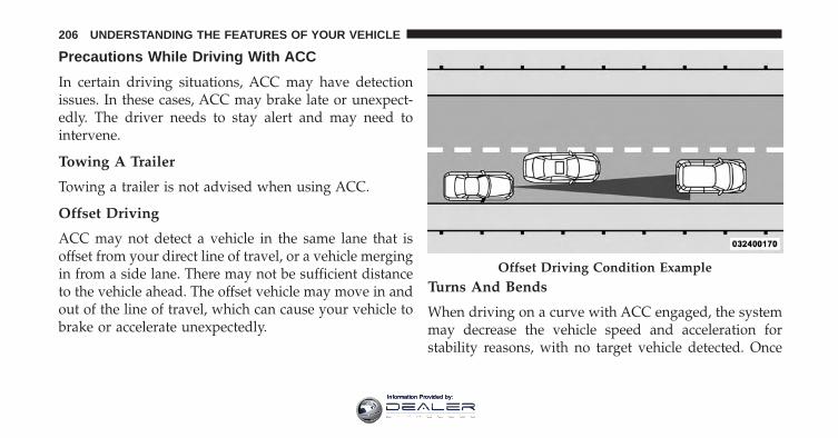
Precautions While Driving With ACC
In certain driving situations, ACC may have detectionissues. In these cases, ACC may brake late or unexpect-edly. The driver needs to stay alert and may need tointervene.
Towing A Trailer
Towing a trailer is not advised when using ACC.
Offset Driving
ACC may not detect a vehicle in the same lane that isoffset from your direct line of travel, or a vehicle mergingin from a side lane. There may not be sufficient distanceto the vehicle ahead. The offset vehicle may move in andout of the line of travel, which can cause your vehicle tobrake or accelerate unexpectedly.
Turns And Bends
When driving on a curve with ACC engaged, the systemmay decrease the vehicle speed and acceleration forstability reasons, with no target vehicle detected. Once
Offset Driving Condition Example
206 UNDERSTANDING THE FEATURES OF YOUR VEHICLE
Information Provided by:
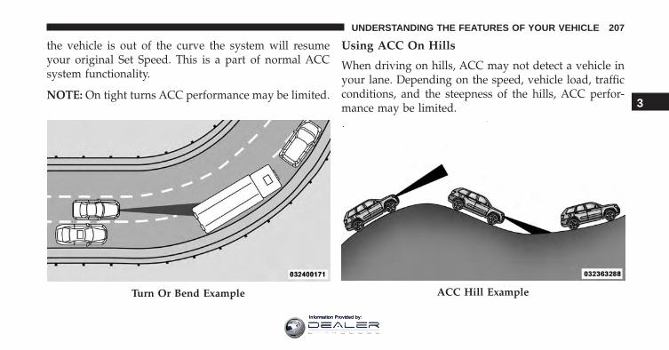
the vehicle is out of the curve the system will resumeyour original Set Speed. This is a part of normal ACCsystem functionality.
NOTE: On tight turns ACC performance may be limited.
Using ACC On Hills
When driving on hills, ACC may not detect a vehicle inyour lane. Depending on the speed, vehicle load, trafficconditions, and the steepness of the hills, ACC perfor-mance may be limited.
Turn Or Bend Example ACC Hill Example
3
UNDERSTANDING THE FEATURES OF YOUR VEHICLE 207
Information Provided by:
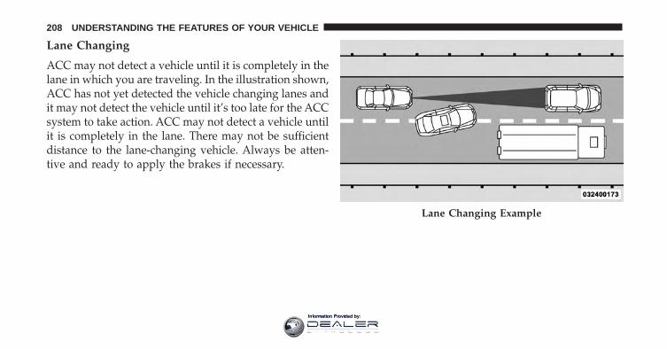
Lane Changing
ACC may not detect a vehicle until it is completely in thelane in which you are traveling. In the illustration shown,ACC has not yet detected the vehicle changing lanes andit may not detect the vehicle until it’s too late for the ACCsystem to take action. ACC may not detect a vehicle untilit is completely in the lane. There may not be sufficientdistance to the lane-changing vehicle. Always be atten-tive and ready to apply the brakes if necessary.
Lane Changing Example
208 UNDERSTANDING THE FEATURES OF YOUR VEHICLE
Information Provided by:
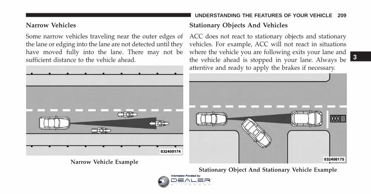
Narrow Vehicles
Some narrow vehicles traveling near the outer edges ofthe lane or edging into the lane are not detected until theyhave moved fully into the lane. There may not besufficient distance to the vehicle ahead.
Stationary Objects And Vehicles
ACC does not react to stationary objects and stationaryvehicles. For example, ACC will not react in situationswhere the vehicle you are following exits your lane andthe vehicle ahead is stopped in your lane. Always beattentive and ready to apply the brakes if necessary.
Narrow Vehicle ExampleStationary Object And Stationary Vehicle Example
3
UNDERSTANDING THE FEATURES OF YOUR VEHICLE 209
Information Provided by:
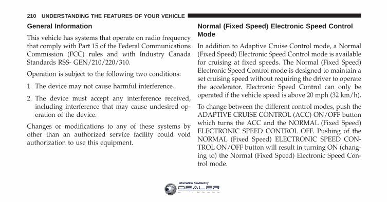
General Information
This vehicle has systems that operate on radio frequencythat comply with Part 15 of the Federal CommunicationsCommission (FCC) rules and with Industry CanadaStandards RSS- GEN/210/220/310.
Operation is subject to the following two conditions:
1. The device may not cause harmful interference.
2. The device must accept any interference received,including interference that may cause undesired op-eration of the device.
Changes or modifications to any of these systems byother than an authorized service facility could voidauthorization to use this equipment.
Normal (Fixed Speed) Electronic Speed ControlMode
In addition to Adaptive Cruise Control mode, a Normal(Fixed Speed) Electronic Speed Control mode is availablefor cruising at fixed speeds. The Normal (Fixed Speed)Electronic Speed Control mode is designed to maintain aset cruising speed without requiring the driver to operatethe accelerator. Electronic Speed Control can only beoperated if the vehicle speed is above 20 mph (32 km/h).
To change between the different control modes, push theADAPTIVE CRUISE CONTROL (ACC) ON/OFF buttonwhich turns the ACC and the NORMAL (Fixed Speed)ELECTRONIC SPEED CONTROL OFF. Pushing of theNORMAL (Fixed Speed) ELECTRONIC SPEED CON-TROL ON/OFF button will result in turning ON (chang-ing to) the Normal (Fixed Speed) Electronic Speed Con-trol mode.
210 UNDERSTANDING THE FEATURES OF YOUR VEHICLE
Information Provided by:
WARNING!
In the normal Cruise Control mode, the system willnot react to vehicles ahead. In addition, the proximitywarning does not activate and no alarm will soundeven if you are too close to the vehicle ahead sinceneither the presence of the vehicle ahead nor thevehicle-to vehicle distance is detected. Be sure tomaintain a safe distance between your vehicle andthe vehicle ahead. Always be aware which mode isselected.
To Set A Desired Speed
Turn the Normal (Fixed Speed) ElectronicSpeed Control ON. When the vehicle hasreached the desired speed, push the SET (+) orSET (-) button and release. Release the accel-
erator and the vehicle will operate at the selected speed.
Once a speed has been set a message (CRUISE CON-TROL SET TO MPH/KM) will appear indicating whatspeed was set. This light will turn on when the electronicspeed control is SET.
To Vary The Speed Setting
To Increase Speed
When the Normal (Fixed Speed) Electronic Speed Controlis set, you can increase speed by pushing the SET + button.
The drivers preferred units can be selected through theinstrument panel settings if equipped. Refer to “Under-standing Your Instrument Panel” for more information.The speed increment shown is dependant on the speed ofU.S. (mph) or Metric (km/h) units:
U.S. Speed (mph)
• Pushing the SET + button once will result in a 1 mphincrease in set speed. Each subsequent tap of thebutton results in an increase of 1 mph.
3
UNDERSTANDING THE FEATURES OF YOUR VEHICLE 211
Information Provided by:
• If the button is continually pushed, the set speed willcontinue to increase in 5 mph increments until thebutton is released. The increase in set speed is reflectedin the EVIC/DID display.
Metric Speed (km/h)
• Pushing the SET + button once will result in a 1 km/hincrease in set speed. Each subsequent tap of thebutton results in an increase of 1 km/h.
• If the button is continually pushed, the set speed willcontinue to increase in 10 km/h increments until thebutton is released. The increase in set speed is reflectedin the EVIC/DID display.
To Decrease Speed
When the Normal (Fixed Speed) Cruise Control is set,you can decrease speed by pushing the SET - button.
The drivers preferred units can be selected through theinstrument panel settings if equipped. Refer to “Under-standing Your Instrument Panel” for more information.The speed decrement shown is dependant on the speedof U.S. (mph) or Metric (km/h) units:
U.S. Speed (mph)
• Pushing the SET - button once will result in a 1 mphdecrease in set speed. Each subsequent tap of thebutton results in a decrease of 1 mph.
• If the button is continually pushed, the set speed willcontinue to decrease in 5 mph decrements until thebutton is released. The decrease in set speed is re-flected in the EVIC/DID display.
Metric Speed (km/h)
• Pushing the SET - button once will result in a 1 km/hdecrease in set speed. Each subsequent tap of thebutton results in a decrease of 1 km/h.
212 UNDERSTANDING THE FEATURES OF YOUR VEHICLE
Information Provided by:
• If the button is continually pushed, the set speed willcontinue to decrease in 10 km/h decrements until thebutton is released. The decrease in set speed is re-flected in the EVIC/DID display.
To Cancel
The following conditions will cancel the Normal (FixedSpeed) Electronic Speed Control without clearing thememory:
• The brake pedal is applied.
• The CANCEL button is pushed.
• The Electronic Stability Control/Traction Control Sys-tem (ESC/TCS) activates.
• The vehicle parking brake is applied.
• The braking temperature exceeds normal range (over-heated).
• The shift lever/gear selector is removed from theDrive position.
To Resume Speed
To resume a previously set speed, push the RES buttonand release. Resume can be used at any speed above20 mph (32 km/h).
To Turn Off
The system will turn off and erase the set speed inmemory if:
• The Normal (Fixed Speed) Electronic Speed ControlON/OFF button is pushed.
• The ignition is turned off.
• You engage Four-Wheel Drive Low.
• The Adaptive Cruise Control (ACC) On/Off button ispushed.
3
UNDERSTANDING THE FEATURES OF YOUR VEHICLE 213
Information Provided by:
FORWARD COLLISION WARNING (FCW) WITHMITIGATION — IF EQUIPPED
Forward Collision Warning (FCW) With MitigationOperation
The Forward Collision Warning (FCW) system withmitigation provides the driver with audible warnings,visual warnings (within the EVIC/DID), and may applya brake jerk to warn the driver when it detects a potentialfrontal collision. The warnings and limited braking areintended to provide the driver with enough time to react,avoid or mitigate the potential collision.
NOTE: FCW monitors the information from the forwardlooking sensors as well as the Electronic Brake Controller(EBC), to calculate the probability of a forward collision.When the system determines that a forward collision isprobable, the driver will be provided with audible andvisual warnings and may provide a brake jerk warning.
If the driver does not take action based upon theseprogressive warnings, then the system will provide alimited level of active braking to help slow the vehicleand mitigate the potential forward collision. If the driverreacts to the warnings by braking and the system deter-mines that the driver intends to avoid the collision bybraking but has not applied sufficient brake force, thesystem will compensate and provide additional brakeforce as required.
If a Forward Collision Warning with Mitigation eventbegins at a speed below 20 mph (32 km/h), the systemmay provide the maximum braking possible to mitigatethe potential forward collision. If the Forward CollisionWarning with Mitigation event stops the vehicle com-pletely, the system will hold the vehicle at standstill fortwo seconds and then release the brakes.
214 UNDERSTANDING THE FEATURES OF YOUR VEHICLE
Information Provided by:
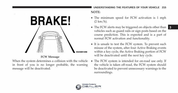
When the system determines a collision with the vehiclein front of you is no longer probable, the warningmessage will be deactivated.
NOTE:
• The minimum speed for FCW activation is 1 mph(2 km/h).
• The FCW alerts may be triggered on objects other thanvehicles such as guard rails or sign posts based on thecourse prediction. This is expected and is a part ofnormal FCW activation and functionality.
• It is unsafe to test the FCW system. To prevent suchmisuse of the system, after four Active Braking eventswithin a key cycle, the Active Braking portion of FCWwill be deactivated until the next key cycle.
• The FCW system is intended for on-road use only. Ifthe vehicle is taken off-road, the FCW system shouldbe deactivated to prevent unnecessary warnings to thesurroundings.
FCW Message
3
UNDERSTANDING THE FEATURES OF YOUR VEHICLE 215
Information Provided by:
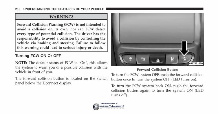
WARNING!
Forward Collision Warning (FCW) is not intended toavoid a collision on its own, nor can FCW detectevery type of potential collision. The driver has theresponsibility to avoid a collision by controlling thevehicle via braking and steering. Failure to followthis warning could lead to serious injury or death.
Turning FCW ON Or OFF
NOTE: The default status of FCW is “On”, this allowsthe system to warn you of a possible collision with thevehicle in front of you.
The forward collision button is located on the switchpanel below the Uconnect display.
To turn the FCW system OFF, push the forward collisionbutton once to turn the system OFF (LED turns on).
To turn the FCW system back ON, push the forwardcollision button again to turn the system ON (LEDturns off).
Forward Collision Button
216 UNDERSTANDING THE FEATURES OF YOUR VEHICLE
Information Provided by:
• Changing the FCW status to “Off” prevents the systemfrom warning you of a possible collision with thevehicle in front of you.
• Changing the FCW sensitivity - Near vs. Far. Far warnsthe driver of a possible collision earlier and Nearwarns the driver later.
• Changing the Active Braking status to “Off” preventsthe system from providing limited active braking, oradditional brake support if the driver is not brakingadequately in the event of a potential frontal collision,but maintains the audible and visual warnings.
NOTE: The FCW system state is kept in memory fromone key cycle to the next. If the system is turned OFF, itwill remain off when the vehicle is restarted.
Changing FCW And Active Braking Status
The FCW Sensitivity And Active Braking Settings areprogrammable through the Uconnect System. Refer to“Uconnect Settings” in “Understanding Your InstrumentPanel” for further information.
The default status of FCW is the “Far” setting and theActive Braking is the “On” setting, this allows the systemto warn you of a possible collision with the vehicle infront of you when you are farther away and it applieslimited braking. This gives you the most reaction time toavoid a possible collision.
Changing the FCW status to the “Near” setting, allowsthe system to warn you of a possible collision with thevehicle in front of you when you are much closer. Thissetting provides less reaction time than the “Far” setting,which allows for a more dynamic driving experience.
3
UNDERSTANDING THE FEATURES OF YOUR VEHICLE 217
Information Provided by:
NOTE:
• The system will retain the last setting selected by thedriver after ignition shut down.
• FCW may not react to irrelevant objects such asoverhead objects, ground reflections, objects not in thepath of the vehicle, stationary objects that are far away,oncoming traffic, or leading vehicles with the same orhigher rate of speed.
• FCW will be disabled like ACC, with the unavailablescreens.
FCW Limited Warning
If the EVIC/DID displays “ACC/FCW Limited Function-ality” or “ACC/FCW Limited Functionality Clean FrontWindshield” momentarily, there may be a condition thatlimits FCW functionality. Although the vehicle is stilldrivable under normal conditions, the active brakingmay not be fully available. Once the condition that
limited the system performance is no longer present, thesystem will return to its full performance state. If theproblem persists, see your authorized dealer.
Service FCW Warning
If the system turns off, and the EVIC/DID displays:
• ACC/FCW Unavailable Service Required
• Cruise/FCW Unavailable Service Required
This indicates there is an internal system fault. Althoughthe vehicle is still drivable under normal conditions, havethe system checked by an authorized dealer.
LANESENSE — IF EQUIPPED
LaneSense Operation
The LaneSense system is operational at speeds above37 mph (60 km/h) and below 112 mph (180 km/h). The
218 UNDERSTANDING THE FEATURES OF YOUR VEHICLE
Information Provided by:
LaneSense system uses a forward looking camera todetect lane markings and measure vehicle positionwithin the lane boundaries.
When both lane markings are detected and the driverunintentionally drifts out of the lane (no turn signalapplied), the LaneSense system provides a haptic warn-ing in the form of torque applied to the steering wheel toprompt the driver to remain within the lane boundaries.If the driver continues to unintentionally drift out of thelane, the LaneSense system provides a visual warningthrough the Electronic Vehicle Information Center (EVIC)or Driver Information Display (DID) to prompt the driverto remain within the lane boundaries.
The driver may manually override the haptic warning byapplying torque into the steering wheel at any time.
When only a single lane marking is detected and thedriver unintentionally drifts across the lane marking (noturn signal applied), the LaneSense system provides a
visual warning through the EVIC/DID to prompt thedriver to remain within the lane. When only a single lanemarking is detected, a haptic (torque) warning will not beprovided.
NOTE: When operating conditions have been met, theLaneSense system will monitor if the driver’s hands areon the steering wheel and provides an audible warningto the driver when the driver’s hands are not detected onthe steering wheel. The system will cancel if the driverdoes not return their hands to the wheel.
Turning LaneSense ON Or OFF
The default status of LaneSense is “OFF”.
The LaneSense button is located on the switch panelbelow the Uconnect display.
3
UNDERSTANDING THE FEATURES OF YOUR VEHICLE 219
Information Provided by:
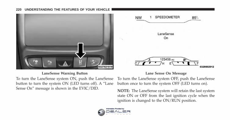
To turn the LaneSense system ON, push the LaneSensebutton to turn the system ON (LED turns off). A “LaneSense On” message is shown in the EVIC/DID.
To turn the LaneSense system OFF, push the LaneSensebutton once to turn the system OFF (LED turns on).
NOTE: The LaneSense system will retain the last systemstate ON or OFF from the last ignition cycle when theignition is changed to the ON/RUN position.
LaneSense Warning Button Lane Sense On Message
220 UNDERSTANDING THE FEATURES OF YOUR VEHICLE
Information Provided by:
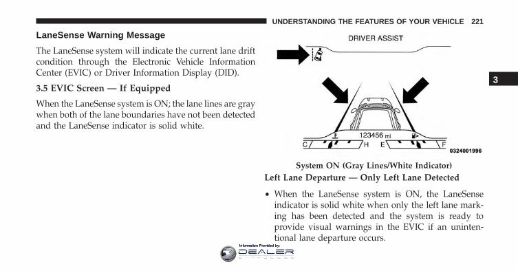
LaneSense Warning Message
The LaneSense system will indicate the current lane driftcondition through the Electronic Vehicle InformationCenter (EVIC) or Driver Information Display (DID).
3.5 EVIC Screen — If Equipped
When the LaneSense system is ON; the lane lines are graywhen both of the lane boundaries have not been detectedand the LaneSense indicator is solid white.
Left Lane Departure — Only Left Lane Detected
• When the LaneSense system is ON, the LaneSenseindicator is solid white when only the left lane mark-ing has been detected and the system is ready toprovide visual warnings in the EVIC if an uninten-tional lane departure occurs.
System ON (Gray Lines/White Indicator)
3
UNDERSTANDING THE FEATURES OF YOUR VEHICLE 221
Information Provided by:
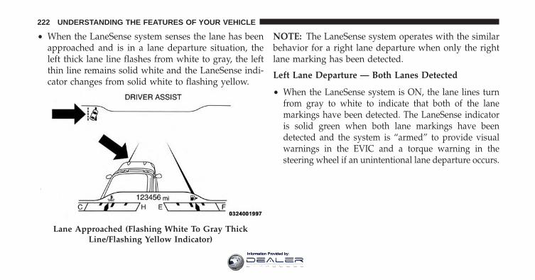
• When the LaneSense system senses the lane has beenapproached and is in a lane departure situation, theleft thick lane line flashes from white to gray, the leftthin line remains solid white and the LaneSense indi-cator changes from solid white to flashing yellow.
NOTE: The LaneSense system operates with the similarbehavior for a right lane departure when only the rightlane marking has been detected.
Left Lane Departure — Both Lanes Detected
• When the LaneSense system is ON, the lane lines turnfrom gray to white to indicate that both of the lanemarkings have been detected. The LaneSense indicatoris solid green when both lane markings have beendetected and the system is “armed” to provide visualwarnings in the EVIC and a torque warning in thesteering wheel if an unintentional lane departure occurs.
Lane Approached (Flashing White To Gray ThickLine/Flashing Yellow Indicator)
222 UNDERSTANDING THE FEATURES OF YOUR VEHICLE
Information Provided by:
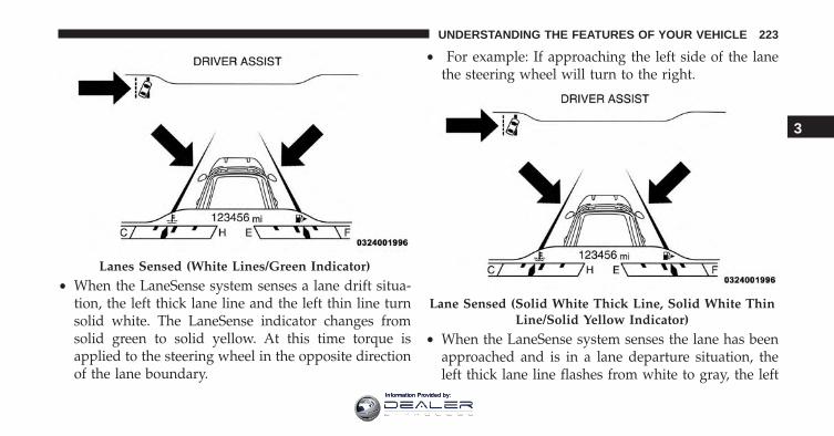
• When the LaneSense system senses a lane drift situa-tion, the left thick lane line and the left thin line turnsolid white. The LaneSense indicator changes fromsolid green to solid yellow. At this time torque isapplied to the steering wheel in the opposite directionof the lane boundary.
• For example: If approaching the left side of the lanethe steering wheel will turn to the right.
• When the LaneSense system senses the lane has beenapproached and is in a lane departure situation, theleft thick lane line flashes from white to gray, the left
Lanes Sensed (White Lines/Green Indicator)
Lane Sensed (Solid White Thick Line, Solid White ThinLine/Solid Yellow Indicator)
3
UNDERSTANDING THE FEATURES OF YOUR VEHICLE 223
Information Provided by:
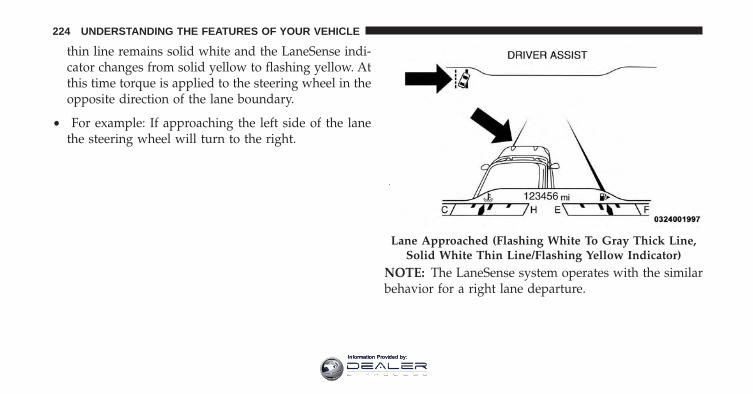
thin line remains solid white and the LaneSense indi-cator changes from solid yellow to flashing yellow. Atthis time torque is applied to the steering wheel in theopposite direction of the lane boundary.
• For example: If approaching the left side of the lanethe steering wheel will turn to the right.
NOTE: The LaneSense system operates with the similarbehavior for a right lane departure.
Lane Approached (Flashing White To Gray Thick Line,Solid White Thin Line/Flashing Yellow Indicator)
224 UNDERSTANDING THE FEATURES OF YOUR VEHICLE
Information Provided by:
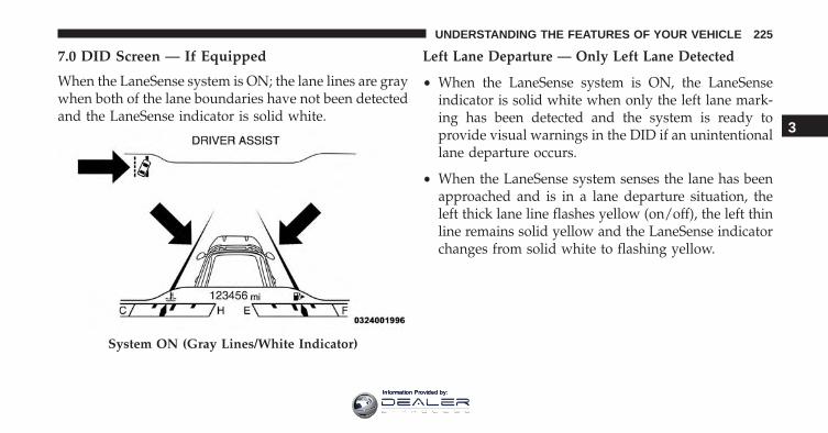
7.0 DID Screen — If Equipped
When the LaneSense system is ON; the lane lines are graywhen both of the lane boundaries have not been detectedand the LaneSense indicator is solid white.
Left Lane Departure — Only Left Lane Detected
• When the LaneSense system is ON, the LaneSenseindicator is solid white when only the left lane mark-ing has been detected and the system is ready toprovide visual warnings in the DID if an unintentionallane departure occurs.
• When the LaneSense system senses the lane has beenapproached and is in a lane departure situation, theleft thick lane line flashes yellow (on/off), the left thinline remains solid yellow and the LaneSense indicatorchanges from solid white to flashing yellow.
System ON (Gray Lines/White Indicator)
3
UNDERSTANDING THE FEATURES OF YOUR VEHICLE 225
Information Provided by:
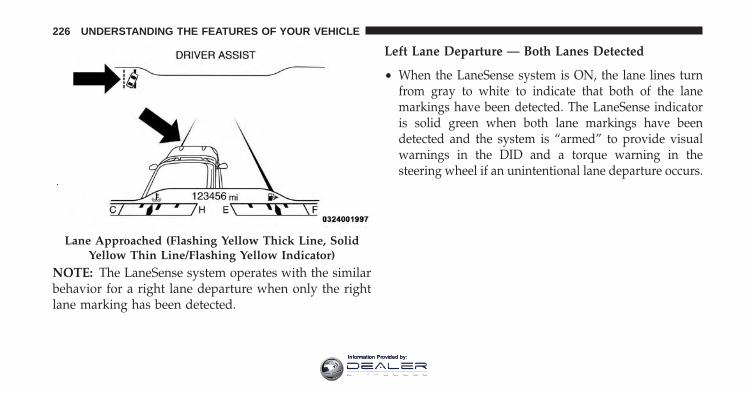
NOTE: The LaneSense system operates with the similarbehavior for a right lane departure when only the rightlane marking has been detected.
Left Lane Departure — Both Lanes Detected
• When the LaneSense system is ON, the lane lines turnfrom gray to white to indicate that both of the lanemarkings have been detected. The LaneSense indicatoris solid green when both lane markings have beendetected and the system is “armed” to provide visualwarnings in the DID and a torque warning in thesteering wheel if an unintentional lane departure occurs.
Lane Approached (Flashing Yellow Thick Line, SolidYellow Thin Line/Flashing Yellow Indicator)
226 UNDERSTANDING THE FEATURES OF YOUR VEHICLE
Information Provided by:
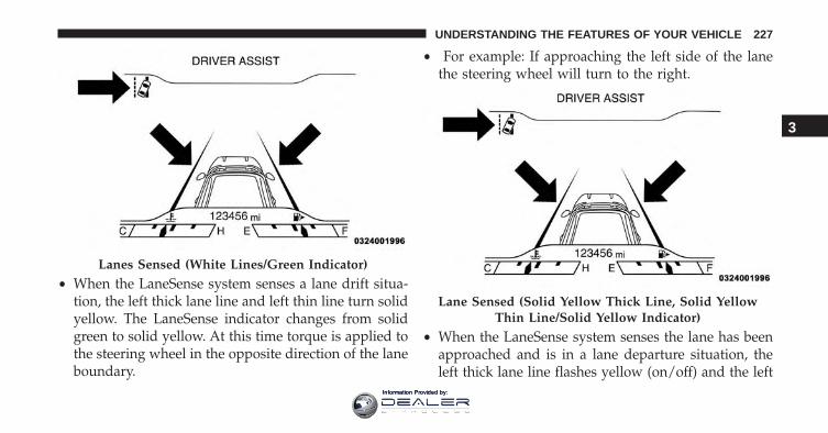
• When the LaneSense system senses a lane drift situa-tion, the left thick lane line and left thin line turn solidyellow. The LaneSense indicator changes from solidgreen to solid yellow. At this time torque is applied tothe steering wheel in the opposite direction of the laneboundary.
• For example: If approaching the left side of the lanethe steering wheel will turn to the right.
• When the LaneSense system senses the lane has beenapproached and is in a lane departure situation, theleft thick lane line flashes yellow (on/off) and the left
Lanes Sensed (White Lines/Green Indicator)
Lane Sensed (Solid Yellow Thick Line, Solid YellowThin Line/Solid Yellow Indicator)
3
UNDERSTANDING THE FEATURES OF YOUR VEHICLE 227
Information Provided by:

thin line remains solid yellow. The LaneSense indicatorchanges from solid yellow to flashing yellow. At thistime torque is applied to the steering wheel in theopposite direction of the lane boundary.
• For example: If approaching the left side of the lanethe steering wheel will turn to the right.
NOTE: The LaneSense system operates with the similarbehavior for a right lane departure.
Lane Approached (Flashing Yellow Thick Line, SolidYellow Thin Line/Flashing Yellow Indicator)
228 UNDERSTANDING THE FEATURES OF YOUR VEHICLE
Information Provided by:
Changing LaneSense Status
The LaneSense system has settings to adjust the intensityof the torque warning and the warning zone sensitivity(early/late) that you can configure through the Uconnectsystem screen. Refer to “Uconnect Settings” in “Under-standing Your Instrument Panel” for further information.
NOTE:
• When enabled the system operates above 37 mph(60 km/h) and below 112 mph (180 km/h).
• Use of the turn signal suppresses the warnings.
• The system will not apply torque to the steering wheelwhenever a safety system engages. (anti-lock brakes,traction control system, electronic stability control,forward collision warning, etc.).
PARKSENSE REAR PARK ASSIST — IFEQUIPPED
The ParkSense Rear Park Assist system provides visualand audible indications of the distance between the rearfascia and a detected obstacle when backing up, e.g.during a parking maneuver. Refer to ParkSense SystemUsage Precautions for limitations of this system andrecommendations.
ParkSense will retain the last system state (enabled ordisabled) from the last ignition cycle when the ignition ischanged to the ON/RUN position.
3
UNDERSTANDING THE FEATURES OF YOUR VEHICLE 229
Information Provided by:
ParkSense can be active only when the shift lever/gearselector is in REVERSE. If ParkSense is enabled at thisshift lever/gear selector position, the system will remainactive until the vehicle speed is increased to approxi-mately 7 mph (11 km/h) or above. When in REVERSEand above the system’s operating speed, a warning willappear within the Electronic Vehicle Information Center(EVIC) or Driver Information Display (DID) indicatingthe vehicle speed is too fast. The system will becomeactive again if the vehicle speed is decreased to speedsless than approximately 6 mph (9 km/h).
ParkSense Sensors
The four ParkSense sensors, located in the rear fascia/bumper, monitor the area behind the vehicle that iswithin the sensors’ field of view. The sensors can detectobstacles from approximately 12 in (30 cm) up to 79 in
(200 cm) from the rear fascia/bumper in the horizontaldirection, depending on the location, type and orienta-tion of the obstacle.
ParkSense Warning Display
The ParkSense Warning screen will only be displayed ifSound and Display is selected from the Customer -Programmable Features section of the Uconnect System.Refer to �Uconnect Settings” in “Understanding YourInstrument Panel” for further information.
The ParkSense Warning screen is located within theEVIC/DID. It provides visual warnings to indicate thedistance between the rear fascia/bumper and the de-tected obstacle. Refer to “Electronic Vehicle InformationCenter (EVIC) or Driver Information Display (DID)” forfurther information.
230 UNDERSTANDING THE FEATURES OF YOUR VEHICLE
Information Provided by:
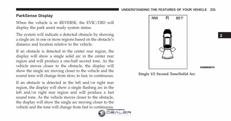
ParkSense Display
When the vehicle is in REVERSE, the EVIC/DID willdisplay the park assist ready system status.
The system will indicate a detected obstacle by showinga single arc in one or more regions based on the obstacle’sdistance and location relative to the vehicle.
If an obstacle is detected in the center rear region, thedisplay will show a single solid arc in the center rearregion and will produce a one-half second tone. As thevehicle moves closer to the obstacle, the display willshow the single arc moving closer to the vehicle and thesound tone will change from slow, to fast, to continuous.
If an obstacle is detected in the left and/or right rearregion, the display will show a single flashing arc in theleft and/or right rear region and will produce a fastsound tone. As the vehicle moves closer to the obstacle,the display will show the single arc moving closer to thevehicle and the tone will change from fast to continuous.
Single 1/2 Second Tone/Solid Arc
3
UNDERSTANDING THE FEATURES OF YOUR VEHICLE 231
Information Provided by:
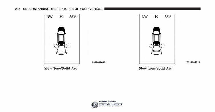
Slow Tone/Solid Arc Slow Tone/Solid Arc
232 UNDERSTANDING THE FEATURES OF YOUR VEHICLE
Information Provided by:
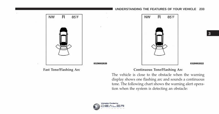
The vehicle is close to the obstacle when the warningdisplay shows one flashing arc and sounds a continuoustone. The following chart shows the warning alert opera-tion when the system is detecting an obstacle:
Fast Tone/Flashing Arc Continuous Tone/Flashing Arc
3
UNDERSTANDING THE FEATURES OF YOUR VEHICLE 233
Information Provided by:
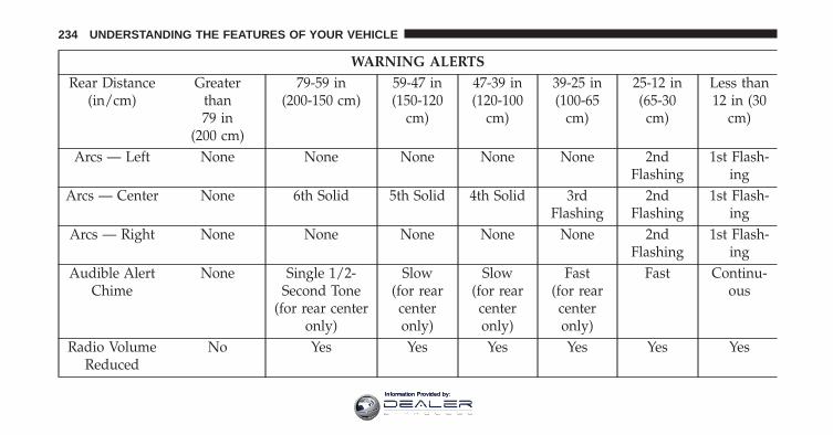
WARNING ALERTSRear Distance
(in/cm)Greater
than79 in
(200 cm)
79-59 in(200-150 cm)
59-47 in(150-120
cm)
47-39 in(120-100
cm)
39-25 in(100-65
cm)
25-12 in(65-30
cm)
Less than12 in (30
cm)
Arcs — Left None None None None None 2ndFlashing
1st Flash-ing
Arcs — Center None 6th Solid 5th Solid 4th Solid 3rdFlashing
2ndFlashing
1st Flash-ing
Arcs — Right None None None None None 2ndFlashing
1st Flash-ing
Audible AlertChime
None Single 1/2-Second Tone
(for rear centeronly)
Slow(for rearcenteronly)
Slow(for rearcenteronly)
Fast(for rearcenteronly)
Fast Continu-ous
Radio VolumeReduced
No Yes Yes Yes Yes Yes Yes
234 UNDERSTANDING THE FEATURES OF YOUR VEHICLE
Information Provided by:
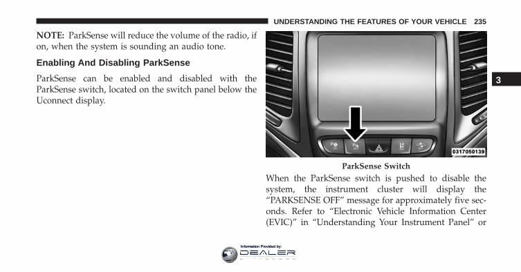
NOTE: ParkSense will reduce the volume of the radio, ifon, when the system is sounding an audio tone.
Enabling And Disabling ParkSense
ParkSense can be enabled and disabled with theParkSense switch, located on the switch panel below theUconnect display.
When the ParkSense switch is pushed to disable thesystem, the instrument cluster will display the“PARKSENSE OFF” message for approximately five sec-onds. Refer to “Electronic Vehicle Information Center(EVIC)” in “Understanding Your Instrument Panel” or
ParkSense Switch
3
UNDERSTANDING THE FEATURES OF YOUR VEHICLE 235
Information Provided by:
“Driver Information Display (DID)” for further informa-tion. When the shift lever is moved to REVERSE and thesystem is disabled, the EVIC/DID will display the“PARKSENSE OFF” message for as long as the vehicle isin REVERSE.
The ParkSense switch LED will be ON when ParkSense isdisabled or requires service. The ParkSense switch LEDwill be OFF when the system is enabled. If the ParkSenseswitch is pushed, and requires service, the ParkSenseswitch LED will blink momentarily, and then the LEDwill be ON.
Service The ParkSense Rear Park Assist System
During vehicle start up, when the ParkSense Rear ParkAssist System has detected a faulted condition, theinstrument cluster will actuate a single chime, once perignition cycle, and it will display the “PARKSENSEUNAVAILABLE WIPE REAR SENSORS” or the“PARKSENSE UNAVAILABLE SERVICE REQUIRED”
message. Refer to “Electronic Vehicle Information Center(EVIC) or Driver Information Display (DID)” for furtherinformation. When the shift lever/gear selector is movedto REVERSE and the system has detected a faultedcondition, the EVIC/DID will display the �PARKSENSEUNAVAILABLE WIPE REAR SENSORS� or�PARKSENSE UNAVAILABLE SERVICE REQUIRED�message for as long as the vehicle is in REVERSE. Underthis condition, ParkSense will not operate.
If “PARKSENSE UNAVAILABLE WIPE REAR SEN-SORS” appears in the Electronic Vehicle InformationCenter (EVIC) or Driver Information Display (DID) makesure the outer surface and the underside of the rearfascia/bumper is clean and clear of snow, ice, mud, dirtor other obstruction and then cycle the ignition. If themessage continues to appear, see an authorized dealer.
If “PARKSENSE UNAVAILABLE SERVICE REQUIRED”appears in the EVIC/DID, see an authorized dealer.
236 UNDERSTANDING THE FEATURES OF YOUR VEHICLE
Information Provided by:
Cleaning The ParkSense System
Clean the ParkSense sensors with water, car wash soapand a soft cloth. Do not use rough or hard cloths. Do notscratch or poke the sensors. Otherwise, you could dam-age the sensors.
ParkSense System Usage Precautions
NOTE:
• Ensure that the rear bumper is free of snow, ice, mud,dirt and debris to keep the ParkSense system operatingproperly.
• Jackhammers, large trucks, and other vibrations couldaffect the performance of ParkSense.
• When you turn ParkSense OFF, the instrument clusterwill display “PARKSENSE OFF” Furthermore, onceyou turn ParkSense off, it remains off until you turn iton again, even if you cycle the ignition.
• When you move the shift lever to the REVERSEposition and ParkSense is turned OFF, the EVIC/DIDwill display “PARKSENSE OFF” message for as longas the vehicle is in REVERSE.
• ParkSense, when on, will reduce the volume of theradio when it is sounding a tone.
• Clean the ParkSense sensors regularly, taking care notto scratch or damage them. The sensors must not becovered with ice, snow, slush, mud, dirt or debris.Failure to do so can result in the system not workingproperly. The ParkSense system might not detect anobstacle behind the fascia/bumper, or it could providea false indication that an obstacle is behind the fascia/bumper.
• Use the ParkSense switch to turn the ParkSense systemOFF if objects such as bicycle carriers, trailer hitches,etc. are placed within 12 in (30 cm) from the rearfascia/bumper. Failure to do so can result in the
3
UNDERSTANDING THE FEATURES OF YOUR VEHICLE 237
Information Provided by:
system misinterpreting a close object as a sensorproblem, causing the “PARKSENSE UNAVAILABLESERVICE REQUIRED” message to be displayed in theEVIC/DID.
• ParkSense should be disabled when the liftgate is inthe open position and the vehicle is in REVERSE. Anopen liftgate could provide a false indication that anobstacle is behind the vehicle.
CAUTION!
• ParkSense is only a parking aid and it is unable torecognize every obstacle, including small obstacles.Parking curbs might be temporarily detected or notdetected at all. Obstacles located above or belowthe sensors will not be detected when they are inclose proximity.
(Continued)
CAUTION! (Continued)• The vehicle must be driven slowly when using
ParkSense in order to be able to stop in time whenan obstacle is detected. It is recommended that thedriver looks over his/her shoulder when usingParkSense.
WARNING!
• Drivers must be careful when backing up evenwhen using ParkSense. Always check carefullybehind your vehicle, look behind you, and be sureto check for pedestrians, animals, other vehicles,obstructions, and blind spots before backing up.You are responsible for safety and must continue topay attention to your surroundings. Failure to do socan result in serious injury or death.
(Continued)
238 UNDERSTANDING THE FEATURES OF YOUR VEHICLE
Information Provided by:
WARNING! (Continued)• Before using ParkSense, it is strongly recom-
mended that the ball mount and hitch ball assem-bly is disconnected from the vehicle when thevehicle is not used for towing. Failure to do so canresult in injury or damage to vehicles or obstaclesbecause the hitch ball will be much closer to theobstacle than the rear fascia when the loudspeakersounds the continuous tone. Also, the sensorscould detect the ball mount and hitch ball assem-bly, depending on its size and shape, giving a falseindication that an obstacle is behind the vehicle.
PARKSENSE FRONT AND REAR PARK ASSIST —IF EQUIPPED
The ParkSense Park Assist system provides visual andaudible indications of the distance between the rearand/or front fascia and a detected obstacle when backing
up or moving forward, e.g. during a parking maneuver.If your vehicle is equipped with an Automatic Transmis-sion, the vehicle brakes may be automatically appliedand released when performing a reverse parking maneu-ver if the system detects a possible collision with anobstacle.
NOTE:
• The driver can override the automatic braking func-tion by pushing the gas pedal, turning ParkSense offvia ParkSense switch, or changing the gear while theautomatic brakes are being applied.
• Automatic brakes will not be available if ESC is notavailable.
• Automatic brakes will not be available if there is afaulted condition detected with the ParkSense ParkAssist system or the Braking System Module.
3
UNDERSTANDING THE FEATURES OF YOUR VEHICLE 239
Information Provided by:
• The automatic braking function may only be applied ifthe vehicle deceleration is not enough to avoid collid-ing with a detected obstacle.
• The automatic braking function may not be appliedfast enough for obstacles that move toward the rear ofthe vehicle from the left and/or right sides.
• The automatic braking function can be enabled/disabled from the Customer-Programmable Featuressection of the Uconnect System.
• ParkSense will retain its last known configuration statefor the automatic braking function through ignitioncycles.
The automatic braking function is intended to assist thedriver in avoiding possible collisions with detected ob-stacles when backing up in REVERSE gear.
NOTE:
• The driver is always responsible for controlling thevehicle.
• The system is provided to assist the driver and not tosubstitute the driver.
• The driver must stay in full control of the vehicle’sacceleration and braking and is responsible for thevehicle’s movements.
Refer to ParkSense System Usage Precautions for limita-tions of this system and recommendations.
ParkSense will retain the last system state (enabled ordisabled) from the last ignition cycle when the ignition ischanged to the ON/RUN position.
ParkSense can be active only when the shift lever is inREVERSE or DRIVE. If ParkSense is enabled at one ofthese shift lever positions, the system will remain active
240 UNDERSTANDING THE FEATURES OF YOUR VEHICLE
Information Provided by:
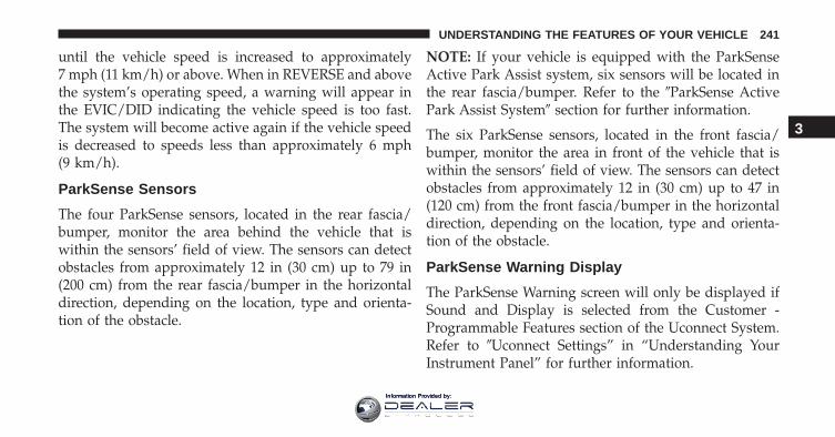
until the vehicle speed is increased to approximately7 mph (11 km/h) or above. When in REVERSE and abovethe system’s operating speed, a warning will appear inthe EVIC/DID indicating the vehicle speed is too fast.The system will become active again if the vehicle speedis decreased to speeds less than approximately 6 mph(9 km/h).
ParkSense Sensors
The four ParkSense sensors, located in the rear fascia/bumper, monitor the area behind the vehicle that iswithin the sensors’ field of view. The sensors can detectobstacles from approximately 12 in (30 cm) up to 79 in(200 cm) from the rear fascia/bumper in the horizontaldirection, depending on the location, type and orienta-tion of the obstacle.
NOTE: If your vehicle is equipped with the ParkSenseActive Park Assist system, six sensors will be located inthe rear fascia/bumper. Refer to the �ParkSense ActivePark Assist System� section for further information.
The six ParkSense sensors, located in the front fascia/bumper, monitor the area in front of the vehicle that iswithin the sensors’ field of view. The sensors can detectobstacles from approximately 12 in (30 cm) up to 47 in(120 cm) from the front fascia/bumper in the horizontaldirection, depending on the location, type and orienta-tion of the obstacle.
ParkSense Warning Display
The ParkSense Warning screen will only be displayed ifSound and Display is selected from the Customer -Programmable Features section of the Uconnect System.Refer to �Uconnect Settings” in “Understanding YourInstrument Panel” for further information.
3
UNDERSTANDING THE FEATURES OF YOUR VEHICLE 241
Information Provided by:
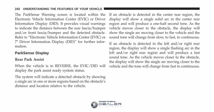
The ParkSense Warning screen is located within theElectronic Vehicle Information Center (EVIC) or DriverInformation Display (DID). It provides visual warningsto indicate the distance between the rear fascia/bumperand/or front fascia/bumper and the detected obstacle.Refer to “Electronic Vehicle Information Center (EVIC) or7� Driver Information Display (DID)” for further infor-mation.
ParkSense Display
Rear Park Assist
When the vehicle is in REVERSE, the EVIC/DID willdisplay the park assist ready system status.
The system will indicate a detected obstacle by showinga single arc in one or more regions based on the obstacle’sdistance and location relative to the vehicle.
If an obstacle is detected in the center rear region, thedisplay will show a single solid arc in the center rearregion and will produce a one-half second tone. As thevehicle moves closer to the obstacle, the display willshow the single arc moving closer to the vehicle and thesound tone will change from slow, to fast, to continuous.
If an obstacle is detected in the left and/or right rearregion, the display will show a single flashing arc in theleft and/or right rear region and will produce a fastsound tone. As the vehicle moves closer to the obstacle,the display will show the single arc moving closer to thevehicle and the tone will change from fast to continuous.
242 UNDERSTANDING THE FEATURES OF YOUR VEHICLE
Information Provided by:
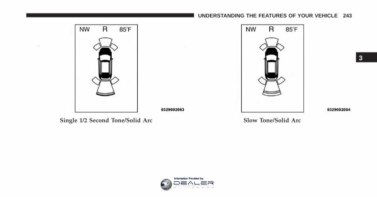
Single 1/2 Second Tone/Solid Arc Slow Tone/Solid Arc
3
UNDERSTANDING THE FEATURES OF YOUR VEHICLE 243
Information Provided by:
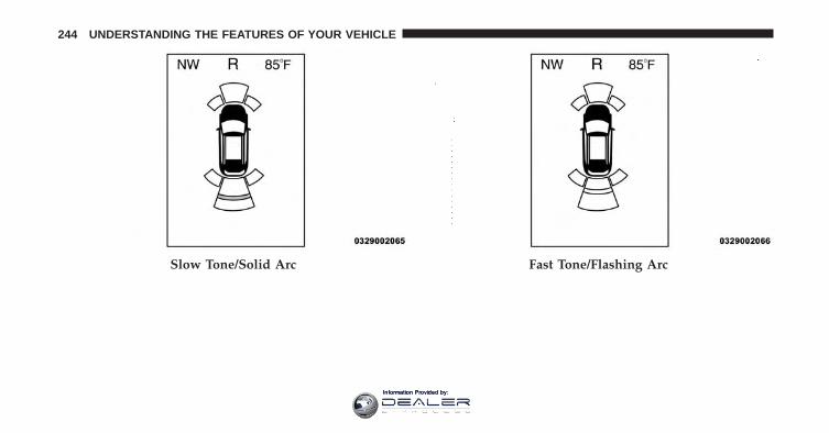
Slow Tone/Solid Arc Fast Tone/Flashing Arc
244 UNDERSTANDING THE FEATURES OF YOUR VEHICLE
Information Provided by:

The vehicle is close to the obstacle when the warningdisplay shows one flashing arc and sounds a continuoustone. The following chart shows the warning alert opera-tion when the system is detecting an obstacle:
Fast Tone/Flashing Arc Continuous Tone/Flashing Arc
3
UNDERSTANDING THE FEATURES OF YOUR VEHICLE 245
Information Provided by:
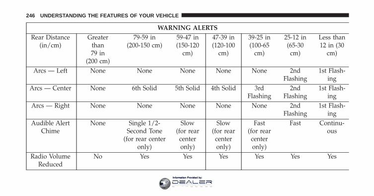
WARNING ALERTSRear Distance
(in/cm)Greater
than79 in
(200 cm)
79-59 in(200-150 cm)
59-47 in(150-120
cm)
47-39 in(120-100
cm)
39-25 in(100-65
cm)
25-12 in(65-30
cm)
Less than12 in (30
cm)
Arcs — Left None None None None None 2ndFlashing
1st Flash-ing
Arcs — Center None 6th Solid 5th Solid 4th Solid 3rdFlashing
2ndFlashing
1st Flash-ing
Arcs — Right None None None None None 2ndFlashing
1st Flash-ing
Audible AlertChime
None Single 1/2-Second Tone
(for rear centeronly)
Slow(for rearcenteronly)
Slow(for rearcenteronly)
Fast(for rearcenteronly)
Fast Continu-ous
Radio VolumeReduced
No Yes Yes Yes Yes Yes Yes
246 UNDERSTANDING THE FEATURES OF YOUR VEHICLE
Information Provided by:
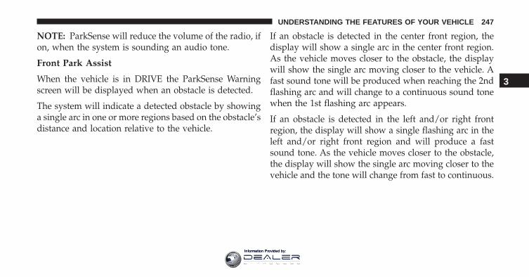
NOTE: ParkSense will reduce the volume of the radio, ifon, when the system is sounding an audio tone.
Front Park Assist
When the vehicle is in DRIVE the ParkSense Warningscreen will be displayed when an obstacle is detected.
The system will indicate a detected obstacle by showinga single arc in one or more regions based on the obstacle’sdistance and location relative to the vehicle.
If an obstacle is detected in the center front region, thedisplay will show a single arc in the center front region.As the vehicle moves closer to the obstacle, the displaywill show the single arc moving closer to the vehicle. Afast sound tone will be produced when reaching the 2ndflashing arc and will change to a continuous sound tonewhen the 1st flashing arc appears.
If an obstacle is detected in the left and/or right frontregion, the display will show a single flashing arc in theleft and/or right front region and will produce a fastsound tone. As the vehicle moves closer to the obstacle,the display will show the single arc moving closer to thevehicle and the tone will change from fast to continuous.
3
UNDERSTANDING THE FEATURES OF YOUR VEHICLE 247
Information Provided by:
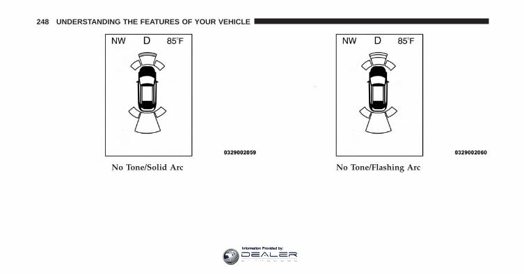
No Tone/Solid Arc No Tone/Flashing Arc
248 UNDERSTANDING THE FEATURES OF YOUR VEHICLE
Information Provided by:
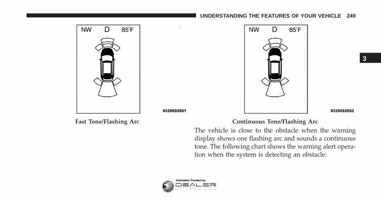
The vehicle is close to the obstacle when the warningdisplay shows one flashing arc and sounds a continuoustone. The following chart shows the warning alert opera-tion when the system is detecting an obstacle:
Fast Tone/Flashing Arc Continuous Tone/Flashing Arc
3
UNDERSTANDING THE FEATURES OF YOUR VEHICLE 249
Information Provided by:
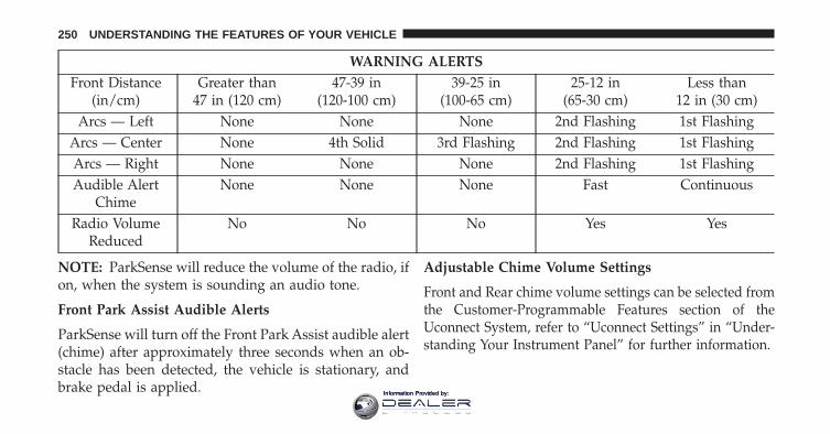
WARNING ALERTSFront Distance
(in/cm)Greater than
47 in (120 cm)47-39 in
(120-100 cm)39-25 in
(100-65 cm)25-12 in
(65-30 cm)Less than
12 in (30 cm)Arcs — Left None None None 2nd Flashing 1st Flashing
Arcs — Center None 4th Solid 3rd Flashing 2nd Flashing 1st FlashingArcs — Right None None None 2nd Flashing 1st FlashingAudible Alert
ChimeNone None None Fast Continuous
Radio VolumeReduced
No No No Yes Yes
NOTE: ParkSense will reduce the volume of the radio, ifon, when the system is sounding an audio tone.
Front Park Assist Audible Alerts
ParkSense will turn off the Front Park Assist audible alert(chime) after approximately three seconds when an ob-stacle has been detected, the vehicle is stationary, andbrake pedal is applied.
Adjustable Chime Volume Settings
Front and Rear chime volume settings can be selected fromthe Customer-Programmable Features section of theUconnect System, refer to “Uconnect Settings” in “Under-standing Your Instrument Panel” for further information.
250 UNDERSTANDING THE FEATURES OF YOUR VEHICLE
Information Provided by:
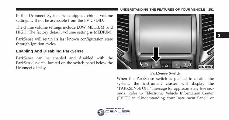
If the Uconnect System is equipped, chime volumesettings will not be accessible from the EVIC/DID.
The chime volume settings include LOW, MEDIUM, andHIGH. The factory default volume setting is MEDIUM.
ParkSense will retain its last known configuration statethrough ignition cycles.
Enabling And Disabling ParkSense
ParkSense can be enabled and disabled with theParkSense switch, located on the switch panel below theUconnect display.
When the ParkSense switch is pushed to disable thesystem, the instrument cluster will display the“PARKSENSE OFF” message for approximately five sec-onds. Refer to “Electronic Vehicle Information Center(EVIC)” in “Understanding Your Instrument Panel” or
ParkSense Switch
3
UNDERSTANDING THE FEATURES OF YOUR VEHICLE 251
Information Provided by:
“Driver Information Display (DID)” for further informa-tion. When the shift lever is moved to REVERSE and thesystem is disabled, the EVIC/DID will display the“PARKSENSE OFF” message for as long as the vehicle isin REVERSE.
The ParkSense switch LED will be ON when ParkSense isdisabled or requires service. The ParkSense switch LEDwill be OFF when the system is enabled. If the ParkSenseswitch is pushed, and requires service, the ParkSenseswitch LED will blink momentarily, and then the LEDwill be ON.
Service The ParkSense Park Assist System
During vehicle start up, when the ParkSense System hasdetected a faulted condition, the instrument cluster willactuate a single chime, once per ignition cycle, and it willdisplay the �PARKSENSE UNAVAILABLE WIPE REARSENSORS�, �PARKSENSE UNAVAILABLE WIPE
FRONT SENSORS�, or the �PARKSENSE UNAVAIL-ABLE SERVICE REQUIRED� message for five seconds.When the shift lever/gear selector is moved to Reverseand the system has detected a faulted condition, theElectronic Vehicle Information Center (EVIC) or DriverInformation Display (DID) will display a �PARKSENSEUNAVAILABLE WIPE REAR SENSORS�, �PARKSENSEUNAVAILABLE WIPE FRONT SENSORS� or�PARKSENSE UNAVAILABLE SERVICE REQUIRED�pop up message for five seconds. After five seconds, a cargraphic will be displayed with �UNAVAILABLE� at ei-ther the front or rear sensor location depending on wherethe fault is detected. The system will continue to providearc alerts for the side that is functioning properly. Thesearc alerts will interrupt the �PARKSENSE UNAVAIL-ABLE WIPE REAR SENSORS�, �PARKSENSE UNAVAIL-ABLE WIPE FRONT SENSORS�, or �PARKSENSE UN-AVAILABLE SERVICE REQUIRED� messages if an objectis detected within the five second pop-up duration. The
252 UNDERSTANDING THE FEATURES OF YOUR VEHICLE
Information Provided by:
car graphic will remain displayed for as long as thevehicle is in REVERSE. Refer to “Electronic VehicleInformation Center (EVIC) or � Driver Information Dis-play (DID)” for further information.
If �PARKSENSE UNAVAILABLE WIPE REAR SENSORS�or �PARKSENSE UNAVAILABLE WIPE FRONT SEN-SORS� appears in the Electronic Vehicle InformationCenter (EVIC) or Driver Information Display (DID) makesure the outer surface and the underside of the rearfascia/bumper and/or front fascia/bumper is clean andclear of snow, ice, mud, dirt or other obstruction and thencycle the ignition. If the message continues to appear seean authorized dealer.
If the �PARKSENSE UNAVAILABLE SERVICE RE-QUIRED� message appears in the EVIC/DID, see anauthorized dealer.
Cleaning The ParkSense System
Clean the ParkSense sensors with water, car wash soapand a soft cloth. Do not use rough or hard cloths. Do notscratch or poke the sensors. Otherwise, you could dam-age the sensors.
ParkSense System Usage Precautions
NOTE:
• Ensure that the front and rear bumper are free of snow,ice, mud, dirt and debris to keep the ParkSense systemoperating properly.
• Construction equipment, large trucks, and other vibra-tions could affect the performance of ParkSense.
• When you turn ParkSense off, the instrument clusterwill display “PARKSENSE OFF.” Furthermore, onceyou turn ParkSense off, it remains off until you turn iton again, even if you cycle the ignition key.
3
UNDERSTANDING THE FEATURES OF YOUR VEHICLE 253
Information Provided by:
• When you move the shift lever to the REVERSEposition and ParkSense is turned off, the instrumentcluster will display “PARKSENSE OFF” for as long asthe vehicle is in REVERSE.
• ParkSense, when on, will reduce the volume of theradio when it is sounding a tone.
• Clean the ParkSense sensors regularly, taking care notto scratch or damage them. The sensors must not becovered with ice, snow, slush, mud, dirt or debris.Failure to do so can result in the system not workingproperly. The ParkSense system might not detect anobstacle behind or in front of the fascia/bumper, or itcould provide a false indication that an obstacle isbehind or in front of the fascia/bumper.
• Use the ParkSense switch to turn the ParkSense systemoff if objects such as bicycle carriers, trailer hitches, etc.are placed within 12 in (30 cm) from the rear fascia/bumper. Failure to do so can result in the system
misinterpreting a close object as a sensor problem,causing the “PARKSENSE UNAVAILABLE SERVICEREQUIRED” message to be displayed in the instru-ment cluster.
• ParkSense should be disabled when the liftgate is inthe open position. An opened liftgate could provide afalse indication that an obstacle is behind the vehicle.
• There may be a delay in the object detection rate if theobject is moving. This will cause the automatic brakingapplication to be delayed.
CAUTION!
• ParkSense is only a parking aid and it is unable torecognize every obstacle, including small obstacles.Parking curbs might be temporarily detected or notdetected at all. Obstacles located above or below
(Continued)
254 UNDERSTANDING THE FEATURES OF YOUR VEHICLE
Information Provided by:
CAUTION! (Continued)the sensors will not be detected when they are inclose proximity.
• The vehicle must be driven slowly when usingParkSense in order to be able to stop in time whenan obstacle is detected. It is recommended that thedriver looks over his/her shoulder when usingParkSense.
WARNING!
• Drivers must be careful when backing up evenwhen using ParkSense. Always check carefullybehind your vehicle, look behind you, and be sureto check for pedestrians, animals, other vehicles,obstructions, and blind spots before backing up.You are responsible for safety and must continue to
(Continued)
WARNING! (Continued)pay attention to your surroundings. Failure to do socan result in serious injury or death.
• Before using ParkSense, it is strongly recom-mended that the ball mount and hitch ball assem-bly is disconnected from the vehicle when thevehicle is not used for towing. Failure to do so canresult in injury or damage to vehicles or obstaclesbecause the hitch ball will be much closer to theobstacle than the rear fascia when the loudspeakersounds the continuous tone. Also, the sensorscould detect the ball mount and hitch ball assem-bly, depending on its size and shape, giving a falseindication that an obstacle is behind the vehicle.
3
UNDERSTANDING THE FEATURES OF YOUR VEHICLE 255
Information Provided by:
PARKSENSE ACTIVE PARK ASSIST SYSTEM —IF EQUIPPED
The ParkSense Active Park Assist system is intended toassist the driver during parallel and perpendicular park-ing maneuvers by identifying a proper parking space,providing audible/visual instructions, and controllingthe steering wheel. The ParkSense Active Park Assistsystem is defined as “semi-automatic” since the drivermaintains control of the accelerator, shift lever andbrakes. Depending on the driver’s parking maneuverselection, the ParkSense Active Park Assist system iscapable of maneuvering a vehicle into a parallel or aperpendicular parking space on either side (i.e., driverside or passenger side).
NOTE:
• The driver is always responsible for controlling thevehicle, responsible for any surrounding objects, andmust intervene as required.
• The system is provided to assist the driver and not tosubstitute the driver.
• During a semi-automatic maneuver, if the drivertouches the steering wheel after being instructed toremove their hands from the steering wheel, the sys-tem will cancel, and the driver will be required tomanually complete the parking maneuver.
• The system may not work in all conditions (e.g.environmental conditions such as heavy rain, snow,etc., or if searching for a parking space that hassurfaces that will absorb the ultrasonic sensor waves).
• New vehicles from the dealership must have at least 30miles accumulated before the ParkSense Active ParkAssist system is fully calibrated and performs accu-rately. This is due to the system’s dynamic vehiclecalibration to improve the performance of the feature.
256 UNDERSTANDING THE FEATURES OF YOUR VEHICLE
Information Provided by:
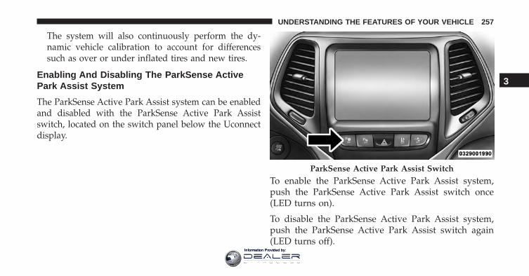
The system will also continuously perform the dy-namic vehicle calibration to account for differencessuch as over or under inflated tires and new tires.
Enabling And Disabling The ParkSense ActivePark Assist System
The ParkSense Active Park Assist system can be enabledand disabled with the ParkSense Active Park Assistswitch, located on the switch panel below the Uconnectdisplay.
To enable the ParkSense Active Park Assist system,push the ParkSense Active Park Assist switch once(LED turns on).
To disable the ParkSense Active Park Assist system,push the ParkSense Active Park Assist switch again(LED turns off).
ParkSense Active Park Assist Switch
3
UNDERSTANDING THE FEATURES OF YOUR VEHICLE 257
Information Provided by:
The ParkSense Active Park Assist system will turn offautomatically for any of the following conditions:
• The parking maneuver is completed.
• Vehicle speed greater than 18 mph (30 km/h) whensearching for a parking space.
• Vehicle speed greater than 5 mph (7 km/h) duringactive steering guidance into the parking space.
• Touching the steering wheel during active steeringguidance into the parking space.
• Pushing the ParkSense Front and Rear Park Assistswitch.
• Driver’s door is opened.
• Rear liftgate is opened.
• Electronic Stability Control/Anti-lock Braking Systemintervention.
• The ParkSense Active Park Assist system will allow amaximum of six shifts between DRIVE and REVERSE.If the maneuver cannot be completed within six shifts,the system will cancel and the EVIC/DID will instructthe driver to complete the maneuver manually.
The ParkSense Active Park Assist system will only oper-ate and search for a parking space when the followingconditions are present:
• Gear position is in DRIVE.
• Ignition is in the RUN position.
• ParkSense Active Park Assist switch is activated.
• Driver’s door is closed.
• Rear liftgate is closed.
• Vehicle speed is less than 15 mph (25 km/h).
258 UNDERSTANDING THE FEATURES OF YOUR VEHICLE
Information Provided by:
NOTE: If the vehicle is driven above approximately15 mph (25 km/h), the EVIC/DID will instruct the driverto slow down. If the vehicle is driven above approxi-mately 18 mph (30 km/h), the system will cancel. Thedriver must then reactivate the system by pushing theParkSense Active Park Assist switch.
• The outer surface and the underside of the front andrear fascias/bumpers are clean and clear of snow, ice,mud, dirt or other obstruction.
When pushed, the LED on the ParkSense Active ParkAssist switch will blink momentarily, and then the LEDwill turn OFF if any of the above conditions are notpresent.
Parallel Parking Space Assistance Operation/Display
When the ParkSense Active Park Assist system is enabledthe “Active ParkSense Searching - Push OK to Switch toPerpendicular” message will appear in the EVIC/DIDdisplay. You may switch to perpendicular parking if youdesire. Push the OK button on the left side steering wheelswitch to change your parking space setting.
NOTE:
• When searching for a parking space, use the turnsignal indicator to select which side of the vehicle youwant to perform the parking maneuver. The ParkSenseActive Park Assist system will automatically search fora parking space on the passenger’s side of the vehicleif the turn signal is not activated.
3
UNDERSTANDING THE FEATURES OF YOUR VEHICLE 259
Information Provided by:
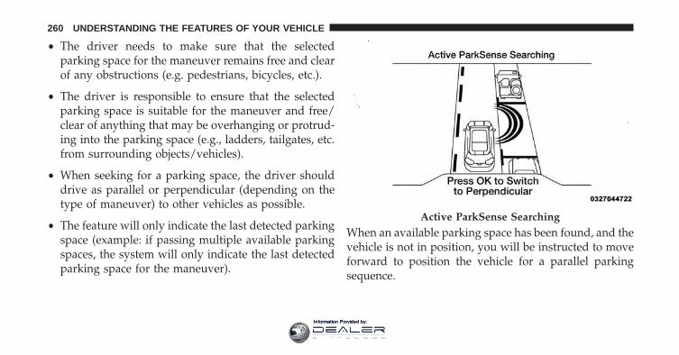
• The driver needs to make sure that the selectedparking space for the maneuver remains free and clearof any obstructions (e.g. pedestrians, bicycles, etc.).
• The driver is responsible to ensure that the selectedparking space is suitable for the maneuver and free/clear of anything that may be overhanging or protrud-ing into the parking space (e.g., ladders, tailgates, etc.from surrounding objects/vehicles).
• When seeking for a parking space, the driver shoulddrive as parallel or perpendicular (depending on thetype of maneuver) to other vehicles as possible.
• The feature will only indicate the last detected parkingspace (example: if passing multiple available parkingspaces, the system will only indicate the last detectedparking space for the maneuver).
When an available parking space has been found, and thevehicle is not in position, you will be instructed to moveforward to position the vehicle for a parallel parkingsequence.
Active ParkSense Searching
260 UNDERSTANDING THE FEATURES OF YOUR VEHICLE
Information Provided by:
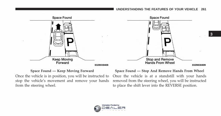
Once the vehicle is in position, you will be instructed tostop the vehicle’s movement and remove your handsfrom the steering wheel.
Once the vehicle is at a standstill with your handsremoved from the steering wheel, you will be instructedto place the shift lever into the REVERSE position.
Space Found — Keep Moving Forward Space Found — Stop And Remove Hands From Wheel
3
UNDERSTANDING THE FEATURES OF YOUR VEHICLE 261
Information Provided by:
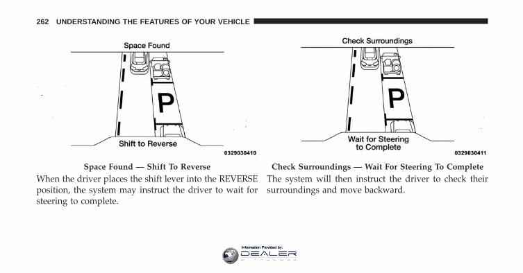
When the driver places the shift lever into the REVERSEposition, the system may instruct the driver to wait forsteering to complete.
The system will then instruct the driver to check theirsurroundings and move backward.
Space Found — Shift To Reverse Check Surroundings — Wait For Steering To Complete
262 UNDERSTANDING THE FEATURES OF YOUR VEHICLE
Information Provided by:
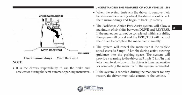
NOTE:
• It is the drivers responsibility to use the brake andaccelerator during the semi-automatic parking maneuver.
• When the system instructs the driver to remove theirhands from the steering wheel, the driver should checktheir surroundings and begin to back up slowly.
• The ParkSense Active Park Assist system will allow amaximum of six shifts between DRIVE and REVERSE.If the maneuver cannot be completed within six shifts,the system will cancel and the EVIC/DID will instructthe driver to complete the maneuver manually.
• The system will cancel the maneuver if the vehiclespeed exceeds 5 mph (7 km/h) during active steeringguidance into the parking space. The system willprovide a warning to the driver at 3 mph (5 km/h) thattells them to slow down. The driver is then responsiblefor completing the maneuver if the system is canceled.
• If the system is canceled during the maneuver for anyreason, the driver must take control of the vehicle.
Check Surroundings — Move Backward
3
UNDERSTANDING THE FEATURES OF YOUR VEHICLE 263
Information Provided by:
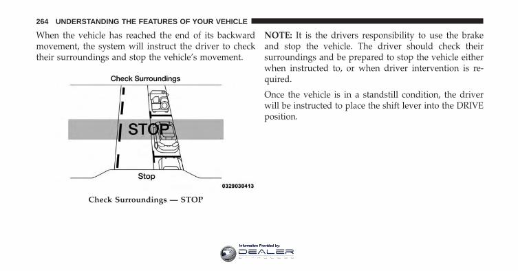
When the vehicle has reached the end of its backwardmovement, the system will instruct the driver to checktheir surroundings and stop the vehicle’s movement.
NOTE: It is the drivers responsibility to use the brakeand stop the vehicle. The driver should check theirsurroundings and be prepared to stop the vehicle eitherwhen instructed to, or when driver intervention is re-quired.
Once the vehicle is in a standstill condition, the driverwill be instructed to place the shift lever into the DRIVEposition.
Check Surroundings — STOP
264 UNDERSTANDING THE FEATURES OF YOUR VEHICLE
Information Provided by:
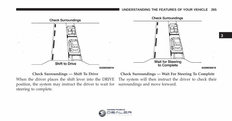
When the driver places the shift lever into the DRIVEposition, the system may instruct the driver to wait forsteering to complete.
The system will then instruct the driver to check theirsurroundings and move forward.
Check Surroundings — Shift To Drive Check Surroundings — Wait For Steering To Complete
3
UNDERSTANDING THE FEATURES OF YOUR VEHICLE 265
Information Provided by:
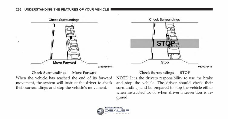
When the vehicle has reached the end of its forwardmovement, the system will instruct the driver to checktheir surroundings and stop the vehicle’s movement.
NOTE: It is the drivers responsibility to use the brakeand stop the vehicle. The driver should check theirsurroundings and be prepared to stop the vehicle eitherwhen instructed to, or when driver intervention is re-quired.
Check Surroundings — Move Forward Check Surroundings — STOP
266 UNDERSTANDING THE FEATURES OF YOUR VEHICLE
Information Provided by:
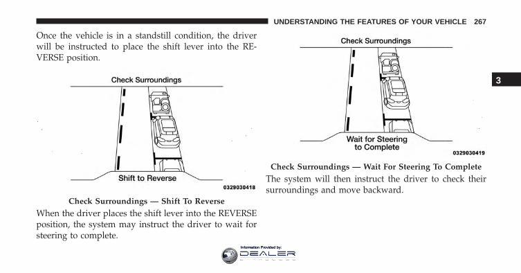
Once the vehicle is in a standstill condition, the driverwill be instructed to place the shift lever into the RE-VERSE position.
When the driver places the shift lever into the REVERSEposition, the system may instruct the driver to wait forsteering to complete.
The system will then instruct the driver to check theirsurroundings and move backward.
Check Surroundings — Shift To Reverse
Check Surroundings — Wait For Steering To Complete
3
UNDERSTANDING THE FEATURES OF YOUR VEHICLE 267
Information Provided by:
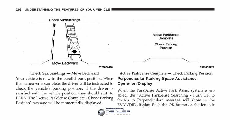
Your vehicle is now in the parallel park position. Whenthe maneuver is complete, the driver will be instructed tocheck the vehicle’s parking position. If the driver issatisfied with the vehicle position, they should shift toPARK. The �Active ParkSense Complete - Check ParkingPosition� message will be momentarily displayed.
Perpendicular Parking Space AssistanceOperation/Display
When the ParkSense Active Park Assist system is en-abled, the “Active ParkSense Searching - Push OK toSwitch to Perpendicular” message will show in theEVIC/DID display. Push the OK button on the left side
Check Surroundings — Move Backward Active ParkSense Complete — Check Parking Position
268 UNDERSTANDING THE FEATURES OF YOUR VEHICLE
Information Provided by:
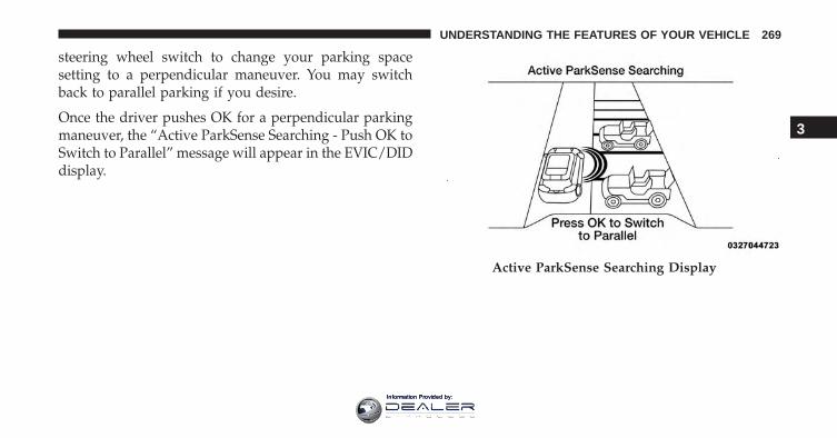
steering wheel switch to change your parking spacesetting to a perpendicular maneuver. You may switchback to parallel parking if you desire.
Once the driver pushes OK for a perpendicular parkingmaneuver, the “Active ParkSense Searching - Push OK toSwitch to Parallel” message will appear in the EVIC/DIDdisplay.
Active ParkSense Searching Display
3
UNDERSTANDING THE FEATURES OF YOUR VEHICLE 269
Information Provided by:
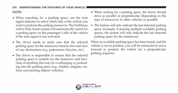
NOTE:
• When searching for a parking space, use the turnsignal indicator to select which side of the vehicle youwant to perform the parking maneuver. The ParkSenseActive Park Assist system will automatically search fora parking space on the passenger’s side of the vehicleif the turn signal is not activated.
• The driver needs to make sure that the selectedparking space for the maneuver remains free and clearof any obstructions (e.g. pedestrians, bicycles, etc.).
• The driver is responsible to ensure that the selectedparking space is suitable for the maneuver and free/clear of anything that may be overhanging or protrud-ing into the parking space (e.g., ladders, tailgates, etc.from surrounding objects/vehicles).
• When seeking for a parking space, the driver shoulddrive as parallel or perpendicular (depending on thetype of maneuver) to other vehicles as possible.
• The feature will only indicate the last detected parkingspace (example: if passing multiple available parkingspaces, the system will only indicate the last detectedparking space for the maneuver).
When an available parking space has been found, and thevehicle is not in position, you will be instructed to moveforward to position the vehicle for a perpendicularparking sequence.
270 UNDERSTANDING THE FEATURES OF YOUR VEHICLE
Information Provided by:
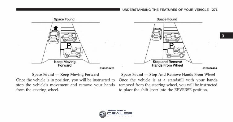
Once the vehicle is in position, you will be instructed tostop the vehicle’s movement and remove your handsfrom the steering wheel.
Once the vehicle is at a standstill with your handsremoved from the steering wheel, you will be instructedto place the shift lever into the REVERSE position.
Space Found — Keep Moving Forward Space Found — Stop And Remove Hands From Wheel
3
UNDERSTANDING THE FEATURES OF YOUR VEHICLE 271
Information Provided by:
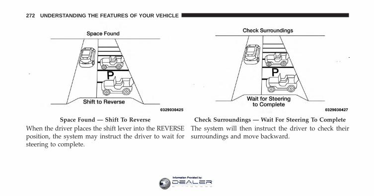
When the driver places the shift lever into the REVERSEposition, the system may instruct the driver to wait forsteering to complete.
The system will then instruct the driver to check theirsurroundings and move backward.
Space Found — Shift To Reverse Check Surroundings — Wait For Steering To Complete
272 UNDERSTANDING THE FEATURES OF YOUR VEHICLE
Information Provided by:
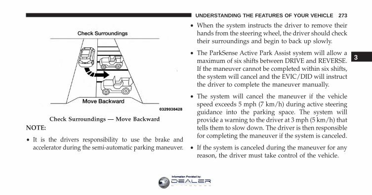
NOTE:
• It is the drivers responsibility to use the brake andaccelerator during the semi-automatic parking maneuver.
• When the system instructs the driver to remove theirhands from the steering wheel, the driver should checktheir surroundings and begin to back up slowly.
• The ParkSense Active Park Assist system will allow amaximum of six shifts between DRIVE and REVERSE.If the maneuver cannot be completed within six shifts,the system will cancel and the EVIC/DID will instructthe driver to complete the maneuver manually.
• The system will cancel the maneuver if the vehiclespeed exceeds 5 mph (7 km/h) during active steeringguidance into the parking space. The system willprovide a warning to the driver at 3 mph (5 km/h) thattells them to slow down. The driver is then responsiblefor completing the maneuver if the system is canceled.
• If the system is canceled during the maneuver for anyreason, the driver must take control of the vehicle.
Check Surroundings — Move Backward
3
UNDERSTANDING THE FEATURES OF YOUR VEHICLE 273
Information Provided by:
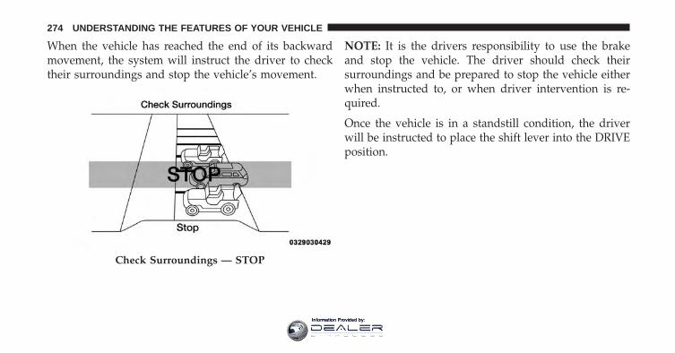
When the vehicle has reached the end of its backwardmovement, the system will instruct the driver to checktheir surroundings and stop the vehicle’s movement.
NOTE: It is the drivers responsibility to use the brakeand stop the vehicle. The driver should check theirsurroundings and be prepared to stop the vehicle eitherwhen instructed to, or when driver intervention is re-quired.
Once the vehicle is in a standstill condition, the driverwill be instructed to place the shift lever into the DRIVEposition.
Check Surroundings — STOP
274 UNDERSTANDING THE FEATURES OF YOUR VEHICLE
Information Provided by:
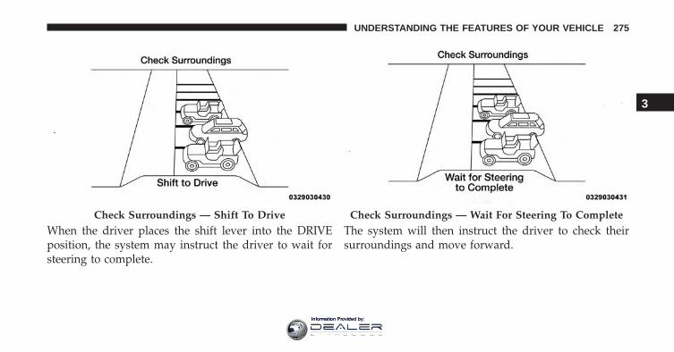
When the driver places the shift lever into the DRIVEposition, the system may instruct the driver to wait forsteering to complete.
The system will then instruct the driver to check theirsurroundings and move forward.
Check Surroundings — Shift To Drive Check Surroundings — Wait For Steering To Complete
3
UNDERSTANDING THE FEATURES OF YOUR VEHICLE 275
Information Provided by:
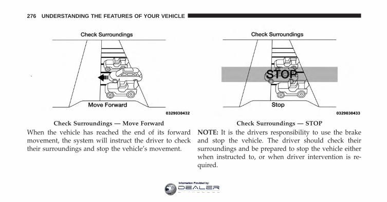
When the vehicle has reached the end of its forwardmovement, the system will instruct the driver to checktheir surroundings and stop the vehicle’s movement.
NOTE: It is the drivers responsibility to use the brakeand stop the vehicle. The driver should check theirsurroundings and be prepared to stop the vehicle eitherwhen instructed to, or when driver intervention is re-quired.
Check Surroundings — Move Forward Check Surroundings — STOP
276 UNDERSTANDING THE FEATURES OF YOUR VEHICLE
Information Provided by:
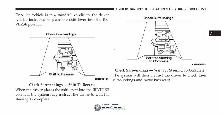
Once the vehicle is in a standstill condition, the driverwill be instructed to place the shift lever into the RE-VERSE position.
When the driver places the shift lever into the REVERSEposition, the system may instruct the driver to wait forsteering to complete.
The system will then instruct the driver to check theirsurroundings and move backward.
Check Surroundings — Shift To Reverse
Check Surroundings — Wait For Steering To Complete
3
UNDERSTANDING THE FEATURES OF YOUR VEHICLE 277
Information Provided by:
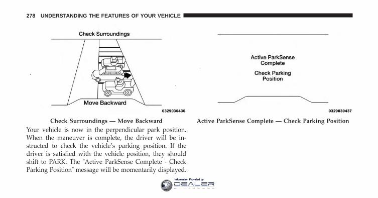
Your vehicle is now in the perpendicular park position.When the maneuver is complete, the driver will be in-structed to check the vehicle’s parking position. If thedriver is satisfied with the vehicle position, they shouldshift to PARK. The �Active ParkSense Complete - CheckParking Position� message will be momentarily displayed.
Check Surroundings — Move Backward Active ParkSense Complete — Check Parking Position
278 UNDERSTANDING THE FEATURES OF YOUR VEHICLE
Information Provided by:
CAUTION!
• The ParkSense Active Park Assist system is only aparking aid and it is unable to recognize everyobstacle, including small obstacles. Parking curbsmight be temporarily detected or not detected atall. Obstacles located above or below the sensorswill not be detected when they are in close prox-imity.
• The vehicle must be driven slowly when using theParkSense Active Park Assist system in order to beable to stop in time when an obstacle is detected. Itis recommended that the driver looks over his/hershoulder when using the ParkSense Active ParkAssist system.
WARNING!
• Drivers must be careful when performing parallelor perpendicular parking maneuvers even whenusing the ParkSense Active Park Assist system.Always check carefully behind and in front of yourvehicle, look behind and in front of you, and besure to check for pedestrians, animals, other ve-hicles, obstructions, and blind spots before back-ing up and moving forward. You are responsiblefor safety and must continue to pay attention toyour surroundings. Failure to do so can result inserious injury or death.
• Before using the ParkSense Active Park Assistsystem, it is strongly recommended that the ballmount and hitch ball assembly is disconnectedfrom the vehicle when the vehicle is not used fortowing. Failure to do so can result in injury or
(Continued)
3
UNDERSTANDING THE FEATURES OF YOUR VEHICLE 279
Information Provided by:
WARNING! (Continued)damage to vehicles or obstacles because the hitchball will be much closer to the obstacle than therear fascia when the loudspeaker sounds the con-tinuous tone. Also, the sensors could detect the ballmount and hitch ball assembly, depending on itssize and shape, giving a false indication that anobstacle is behind the vehicle.
PARKVIEW REAR BACK UP CAMERA — IFEQUIPPED
Your vehicle may be equipped with the ParkView RearBack Up Camera that allows you to see an on-screenimage of the rear surroundings of your vehicle wheneverthe shift lever is put into REVERSE. The image will bedisplayed in the touchscreen display along with a cautionnote to “check entire surroundings” across the top of the
screen. After five seconds this note will disappear. TheParkView camera is located on the rear of the vehicleabove the rear License plate.
NOTE: The ParkView Rear Back Up Camera has pro-grammable modes of operation that may be selectedthrough the Uconnect System. Refer to “Uconnect Set-tings” in “Understanding Your Instrument Panel” forfurther information.
When the vehicle is shifted out of REVERSE (with cameradelay turned OFF), the rear camera mode is exited andthe previous screen appears again. When the vehicle isshifted out of REVERSE (with camera delay turned ON),the camera image will continue to be displayed for up to10 seconds after shifting out of REVERSE unless thevehicle speed exceeds 8 mph (13 km/h), the vehicle isshifted into PARK or the vehicles ignition is cycled to theOFF position.
280 UNDERSTANDING THE FEATURES OF YOUR VEHICLE
Information Provided by:
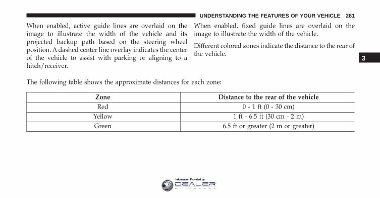
When enabled, active guide lines are overlaid on theimage to illustrate the width of the vehicle and itsprojected backup path based on the steering wheelposition. A dashed center line overlay indicates the centerof the vehicle to assist with parking or aligning to ahitch/receiver.
When enabled, fixed guide lines are overlaid on theimage to illustrate the width of the vehicle.
Different colored zones indicate the distance to the rear ofthe vehicle.
The following table shows the approximate distances for each zone:
Zone Distance to the rear of the vehicleRed 0 - 1 ft (0 - 30 cm)
Yellow 1 ft - 6.5 ft (30 cm - 2 m)Green 6.5 ft or greater (2 m or greater)
3
UNDERSTANDING THE FEATURES OF YOUR VEHICLE 281
Information Provided by:
CAUTION!
• To avoid vehicle damage, ParkView should only beused as a parking aid. The ParkView camera isunable to view every obstacle or object in yourdrive path.
• To avoid vehicle damage, the vehicle must bedriven slowly when using ParkView to be able tostop in time when an obstacle is seen. It is recom-mended that the driver look frequently over his/hershoulder when using ParkView.
WARNING!
Drivers must be careful when backing up even whenusing the ParkView Rear Back Up Camera. Alwayscheck carefully behind your vehicle, and be sure to
(Continued)
WARNING! (Continued)check for pedestrians, animals, other vehicles, ob-structions, or blind spots before backing up. You areresponsible for the safety of your surroundings andmust continue to pay attention while backing up.Failure to do so can result in serious injury or death.
NOTE: If snow, ice, mud, or any foreign substance buildsup on the camera lens, clean the lens, rinse with water,and dry with a soft cloth. Do not cover the lens.
GARAGE DOOR OPENER — IF EQUIPPED
HomeLink replaces up to three remote controls (hand-held transmitters) that operate devices such as garagedoor openers, motorized gates, lighting or home securitysystems. The HomeLink unit operates off your vehicle’sbattery.
282 UNDERSTANDING THE FEATURES OF YOUR VEHICLE
Information Provided by:
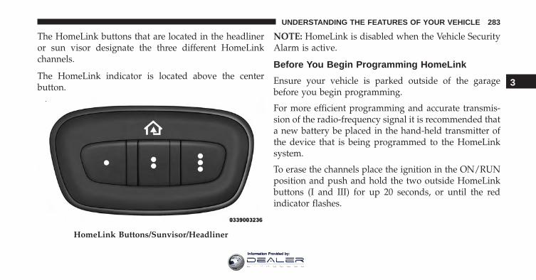
The HomeLink buttons that are located in the headlineror sun visor designate the three different HomeLinkchannels.
The HomeLink indicator is located above the centerbutton.
NOTE: HomeLink is disabled when the Vehicle SecurityAlarm is active.
Before You Begin Programming HomeLink
Ensure your vehicle is parked outside of the garagebefore you begin programming.
For more efficient programming and accurate transmis-sion of the radio-frequency signal it is recommended thata new battery be placed in the hand-held transmitter ofthe device that is being programmed to the HomeLinksystem.
To erase the channels place the ignition in the ON/RUNposition and push and hold the two outside HomeLinkbuttons (I and III) for up 20 seconds, or until the redindicator flashes.
HomeLink Buttons/Sunvisor/Headliner
3
UNDERSTANDING THE FEATURES OF YOUR VEHICLE 283
Information Provided by:
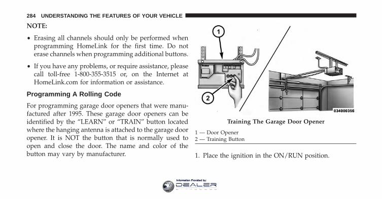
NOTE:
• Erasing all channels should only be performed whenprogramming HomeLink for the first time. Do noterase channels when programming additional buttons.
• If you have any problems, or require assistance, pleasecall toll-free 1-800-355-3515 or, on the Internet atHomeLink.com for information or assistance.
Programming A Rolling Code
For programming garage door openers that were manu-factured after 1995. These garage door openers can beidentified by the “LEARN” or “TRAIN” button locatedwhere the hanging antenna is attached to the garage dooropener. It is NOT the button that is normally used toopen and close the door. The name and color of thebutton may vary by manufacturer. 1. Place the ignition in the ON/RUN position.
Training The Garage Door Opener
1 — Door Opener2 — Training Button
284 UNDERSTANDING THE FEATURES OF YOUR VEHICLE
Information Provided by:
2. Place the hand-held transmitter 1 to 3 inches (3 to 8cm) away from the HomeLink button you wish toprogram while keeping the HomeLink indicator lightin view.
3. Push and hold the HomeLink button you want toprogram while you push and hold the hand-heldtransmitter button.
4. Continue to hold both buttons and observe the indi-cator light. The HomeLink indicator will flash slowlyand then rapidly after HomeLink has received thefrequency signal from the hand-held transmitter. Re-lease both buttons after the indicator light changesfrom slow to rapid.
5. At the garage door opener motor (in the garage),locate the “LEARN” or “TRAINING” button. This canusually be found where the hanging antenna wire isattached to the garage door opener/device motor.
Firmly push and release the “LEARN” or “TRAIN-ING” button. On some garage door openers/devicesthere may be a light that blinks when the garage dooropener/device is in the LEARN/TRAIN mode.
NOTE: You have 30 seconds in which to initiate the nextstep after the LEARN button has been pushed.
6. Return to the vehicle and push the programmedHomeLink button twice (holding the button for twoseconds each time). If the garage door opener/deviceactivates, programming is complete.
NOTE: If the garage door opener/device does not acti-vate, push the button a third time (for two seconds) tocomplete the training.
To program the remaining two HomeLink buttons, repeateach step for each remaining button. DO NOT erase thechannels.
3
UNDERSTANDING THE FEATURES OF YOUR VEHICLE 285
Information Provided by:
Reprogramming A Single HomeLink Button(Rolling Code)
To reprogram a channel that has been previously trained,follow these steps:
1. Cycle the ignition to the ON/RUN position.
2. Push and hold the desired HomeLink button until theindicator light begins to flash after 20 seconds. Do notrelease the button.
3. Without releasing the button proceed with “Program-ming A Rolling Code” step 2 and follow all remainingsteps.
Programming A Non-Rolling Code
For programming Garage Door Openers manufacturedbefore 1995.
1. Cycle the ignition to the ON/RUN position.
2. Place the hand-held transmitter 1 to 3 inches (3 to 8cm) away from the HomeLink button you would liketo program while keeping the HomeLink indicatorlight in view.
3. Push and hold the HomeLink button you want toprogram while you push and hold the hand-heldtransmitter button.
4. Continue to hold both buttons and observe the indi-cator light. HomeLink indicator will flash slowly andthen rapidly after HomeLink has received the fre-quency signal from the hand-held transmitter. Releaseboth buttons after the indicator light changes fromslow to rapid.
5. Push and hold the programmed HomeLink buttonand observe the indicator light.
• If the indicator light stays on constantly, program-ming is complete and the garage door/device shouldactivate when the HomeLink button is pressed.
286 UNDERSTANDING THE FEATURES OF YOUR VEHICLE
Information Provided by:
• To program the remaining two HomeLink buttons,repeat each step for each remaining button. DO NOTerase the channels.
Reprogramming A Single HomeLink Button (Non— Rolling Code)
To reprogram a channel that has been previously trained,follow these steps:
1. Cycle the ignition to the ON/RUN position.
2. Push and hold the desired HomeLink button until theindicator light begins to flash after 20 seconds. Do notrelease the button.
3. Without releasing the button proceed with “Program-ming A Non-Rolling Code” step 2 and follow allremaining steps.
Canadian/Gate Operator Programming
For programming transmitters in Canada/United Statesthat require the transmitter signals to “time-out” afterseveral seconds of transmission.
Canadian radio frequency laws require transmitter sig-nals to time-out (or quit) after several seconds of trans-mission – which may not be long enough for HomeLinkto pick up the signal during programming. Similar to thisCanadian law, some U.S. gate operators are designed totime-out in the same manner.
It may be helpful to unplug the device during the cyclingprocess to prevent possible overheating of the garagedoor or gate motor.
1. Cycle the ignition to the ON/RUN position.
3
UNDERSTANDING THE FEATURES OF YOUR VEHICLE 287
Information Provided by:
2. Place the hand-held transmitter 1 to 3 inches (3 to 8cm) away from the HomeLink button you wish toprogram while keeping the HomeLink indicator lightin view.
3. Continue to push and hold the HomeLink button,while you press and release (“cycle”) your hand-heldtransmitter every two seconds until HomeLink hassuccessfully accepted the frequency signal. The indi-cator light will flash slowly and then rapidly whenfully trained.
4. Watch for the HomeLink indicator to change flashrates. When it changes, it is programmed. It may takeup to 30 seconds or longer in rare cases. The garagedoor may open and close while you are programming.
5. Push and hold the programmed HomeLink buttonand observe the indicator light.
NOTE:
• If the indicator light stays on constantly, program-ming is complete and the garage door/device shouldactivate when the HomeLink button is pushed.
• To program the two remaining HomeLink buttons,repeat each step for each remaining button. DO NOTerase the channels.
If you unplugged the garage door opener/device forprogramming, plug it back in at this time.
Reprogramming A Single HomeLink Button(Canadian/Gate Operator)
To reprogram a channel that has been previously trained,follow these steps:
1. Cycle the ignition to the ON/RUN position.
288 UNDERSTANDING THE FEATURES OF YOUR VEHICLE
Information Provided by:
2. Push and hold the desired HomeLink button until theindicator light begins to flash after 20 seconds. Do notrelease the button.
3. Without releasing the button proceed with“Canadian/Gate Operator Programming” step 2 andfollow all remaining steps.
Using HomeLink
To operate, push and release the programmed HomeLinkbutton. Activation will now occur for the programmeddevice (i.e. garage door opener, gate operator, securitysystem, entry door lock, home/office lighting, etc.) Thehand-held transmitter of the device may also be used atany time.
Security
It is advised to erase all channels before you sell or turnin your vehicle.
To do this, push and hold the two outside buttons for 20seconds until the red indicator flashes. Note that allchannels will be erased. Individual channels cannot beerased.
The HomeLink Universal Transceiver is disabled whenthe Vehicle Security Alarm is active.
Troubleshooting Tips
If you are having trouble programming HomeLink, hereare some of the most common solutions:
• Replace the battery in the Garage Door Opener hand-held transmitter.
• Push the LEARN button on the Garage Door Openerto complete the training for a Rolling Code.
• Did you unplug the device for programming andremember to plug it back in?
3
UNDERSTANDING THE FEATURES OF YOUR VEHICLE 289
Information Provided by:
If you have any problems, or require assistance, pleasecall toll-free 1-800-355-3515 or, on the Internet atHomeLink.com for information or assistance.
WARNING!
• Vehicle exhaust contains carbon monoxide, a dan-gerous gas. Do not run your vehicle in the garagewhile programming the transceiver. Exhaust gascan cause serious injury or death.
• Your motorized door or gate will open and closewhile you are programming the universal trans-ceiver. Do not program the transceiver if people,pets or other objects are in the path of the door orgate. Only use this transceiver with a garage dooropener that has a “stop and reverse” feature asrequired by Federal safety standards. This includesmost garage door opener models manufactured
(Continued)
WARNING! (Continued)after 1982. Do not use a garage door opener withoutthese safety features. Call toll-free 1-800-355-3515or, on the Internet at HomeLink.com for safetyinformation or assistance.
General Information
This device complies with FCC rules Part 15 and IndustryCanada RSS-210. Operation is subject to the followingtwo conditions:
1. This device may not cause harmful interference.
2. This device must accept any interference that may bereceived including interference that may cause unde-sired operation.
290 UNDERSTANDING THE FEATURES OF YOUR VEHICLE
Information Provided by:
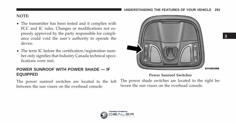
NOTE:
• The transmitter has been tested and it complies withFCC and IC rules. Changes or modifications not ex-pressly approved by the party responsible for compli-ance could void the user’s authority to operate thedevice.
• The term IC before the certification/registration num-ber only signifies that Industry Canada technical speci-fications were met.
POWER SUNROOF WITH POWER SHADE — IFEQUIPPED
The power sunroof switches are located to the leftbetween the sun visors on the overhead console.
The power shade switches are located to the right be-tween the sun visors on the overhead console.
Power Sunroof Switches
3
UNDERSTANDING THE FEATURES OF YOUR VEHICLE 291
Information Provided by:
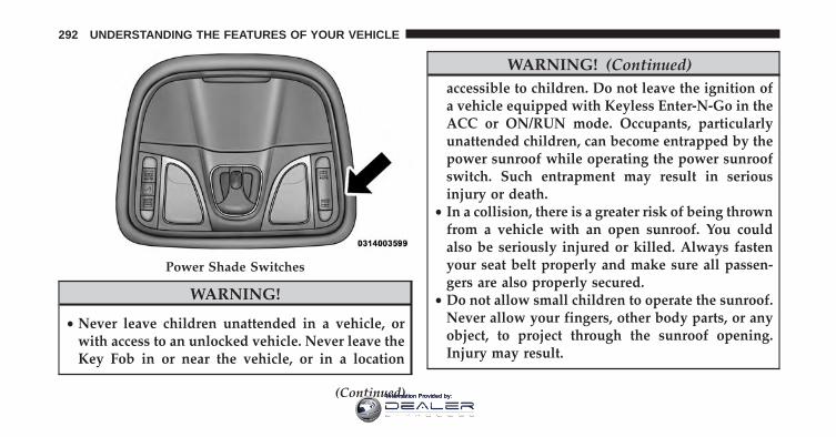
WARNING!
• Never leave children unattended in a vehicle, orwith access to an unlocked vehicle. Never leave theKey Fob in or near the vehicle, or in a location
(Continued)
WARNING! (Continued)accessible to children. Do not leave the ignition ofa vehicle equipped with Keyless Enter-N-Go in theACC or ON/RUN mode. Occupants, particularlyunattended children, can become entrapped by thepower sunroof while operating the power sunroofswitch. Such entrapment may result in seriousinjury or death.
• In a collision, there is a greater risk of being thrownfrom a vehicle with an open sunroof. You couldalso be seriously injured or killed. Always fastenyour seat belt properly and make sure all passen-gers are also properly secured.
• Do not allow small children to operate the sunroof.Never allow your fingers, other body parts, or anyobject, to project through the sunroof opening.Injury may result.
Power Shade Switches
292 UNDERSTANDING THE FEATURES OF YOUR VEHICLE
Information Provided by:
Opening Sunroof — Express
A comfort stop position and full open position are theprogrammed automatic stops for the sunroof open posi-tions. The comfort stop position has been optimized tominimize wind buffeting.
Push the switch rearward and release it within one-halfsecond. The sunroof will open automatically to thecomfort stop position (if the sunshade is in the closedposition when the operation is initiated the sunshade willautomatically open to the half open position prior to thesunroof opening). Push the switch rearward and releaseit again, the sunroof will open to the full open positionand automatically stop. This is called “Express Open”.During Express Open operation, any movement of thesunroof switch will stop the sunroof.
Opening Sunroof — Manual Mode
A comfort stop position is a programmed automatic stopfor the sunroof open position. The comfort stop positionhas been optimized to minimize wind buffeting.
To open the sunroof, push and hold the switch rearward.The sunroof will stop automatically at the comfort stopposition (if the sunshade is in the closed position whenthe operation is initiated the sunshade will automaticallyopen to the half open position prior to the sunroofopening). Push and hold the switch rearward again, thesunroof will open to the full open position and automati-cally stop. Any release of the switch will stop themovement. The sunroof and sunshade will remain in apartially opened condition until the switch is pushed andheld rearward again.
Closing Sunroof — Express
Push the switch forward and release it within one-halfsecond and the sunroof will close automatically from any
3
UNDERSTANDING THE FEATURES OF YOUR VEHICLE 293
Information Provided by:
position. The sunroof will close fully and stop automati-cally. This is called “Express Close.” During ExpressClose operation, any other actuation of the switch willstop the sunroof.
Closing Sunroof — Manual Mode
To close the sunroof, push and hold the switch in theforward position. Any release of the switch will stop themovement and the sunroof will remain in a partiallyclosed condition until the sunroof switch is pushed again.
Venting Sunroof — Express
Push and release the �Vent� button within one-half sec-ond and the sunroof will open to the vent position. Thisis called “Express Vent”, and it will occur regardless ofsunroof position. During Express Vent operation, anymovement of the switch will stop the sunroof.
NOTE: If the sunshade is in the closed position when thevent switch is pushed, the sunshade will automaticallycycle to the halfway open position prior to the sunroofopening to the Vent position.
Opening Power Shade — Express
Push the shade switch rearward and release it withinone-half second and the shade will automatically open tothe halfway position and stop automatically. Push theswitch a second time from the halfway position and theshade will automatically open to the full open positionand stop automatically. This is called “Express Open”.During Express Open operation, any movement of theshade switch will stop the shade.
Opening Power Shade — Manual Mode
To open the shade, push and hold the switch rearward.The shade will open and stop automatically at thehalf-open position. Push and hold the shade switchrearward again and the shade will open automatically to
294 UNDERSTANDING THE FEATURES OF YOUR VEHICLE
Information Provided by:
the full-open position. Any release of the switch will stopthe movement and the shade will remain in a partiallyopened condition until the switch is pushed again.
Closing Power Shade — Express
Push the switch forward and release it within one-halfsecond and the shade will close automatically from anyposition. If the sunroof is completely closed the shadewill close fully and stop automatically. This is called“Express Close”. During Express Close operation, anymovement of the switch will stop the shade.
NOTE: If the sunroof is open, the shade will close to thehalf-open position. Pushing the shade close button againwill automatically close both the sunroof and shadecompletely.
Closing Power Shade — Manual Mode
To close the shade, push and hold the switch in theforward position. Any release of the switch will stop the
movement and the shade will remain in a partially closedcondition until the switch is pushed again.
Pinch Protect Feature
This feature will detect an obstruction in the opening ofthe sunroof during Express Close operation. If an ob-struction in the path of the sunroof is detected, thesunroof will automatically retract. Remove the obstruc-tion if this occurs. Next, push the switch forward andrelease to Express Close.
NOTE: If three consecutive sunroof close attempts resultin Pinch Protect reversals, the fourth close attempt will bea Manual Close movement with Pinch Protect disabled.
Wind Buffeting
Wind buffeting can be described as the perception ofpressure on the ears or a helicopter-type sound in theears. Your vehicle may exhibit wind buffeting with thewindows down, or the sunroof (if equipped) in certain
3
UNDERSTANDING THE FEATURES OF YOUR VEHICLE 295
Information Provided by:
open or partially open positions. This is a normal occur-rence and can be minimized. If the buffeting occurs withthe rear windows open, then open the front and rearwindows together to minimize the buffeting. If thebuffeting occurs with the sunroof open, adjust the sun-roof opening to minimize the buffeting or open anywindow.
Sunroof Maintenance
Use only a non-abrasive cleaner and a soft cloth to cleanthe glass panel.
Ignition OFF Operation
The power sunroof switch will remain active for up toapproximately ten minutes after the ignition switch isturned to the LOCK position. Opening either front doorwill cancel this feature.
NOTE: Ignition Off time is programmable through theUconnect System. Refer to “Uconnect Settings/CustomerProgrammable Features” in “Understanding Your Instru-ment Panel” for further information.
POWER OUTLETS
Your vehicle is equipped with 12 Volt (13 Amp) poweroutlets that can be used to power cellular phones, smallelectronics and other low powered electrical accessories.The power outlets are labeled with either a “key” or a“battery” symbol to indicate how the outlet is powered.Power outlets labeled with a “key” are powered whenthe ignition switch is in the ON or ACC position, whilethe outlets labeled with a “battery” are connected directlyto the battery and powered at all times.
296 UNDERSTANDING THE FEATURES OF YOUR VEHICLE
Information Provided by:
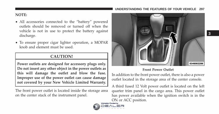
NOTE:
• All accessories connected to the “battery” poweredoutlets should be removed or turned off when thevehicle is not in use to protect the battery againstdischarge.
• To ensure proper cigar lighter operation, a MOPARknob and element must be used.
CAUTION!
Power outlets are designed for accessory plugs only.Do not insert any other object in the power outlets asthis will damage the outlet and blow the fuse.Improper use of the power outlet can cause damagenot covered by your New Vehicle Limited Warranty.
The front power outlet is located inside the storage areaon the center stack of the instrument panel.
In addition to the front power outlet, there is also a poweroutlet located in the storage area of the center console.
A third fused 12 Volt power outlet is located on the leftquarter trim panel in the cargo area. This power outlethas power available when the ignition switch is in theON or ACC position.
Front Power Outlet
3
UNDERSTANDING THE FEATURES OF YOUR VEHICLE 297
Information Provided by:
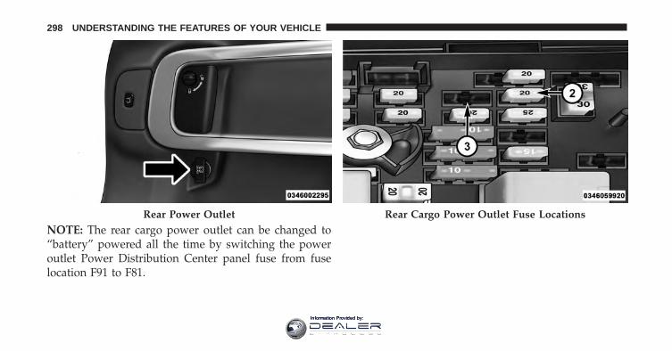
NOTE: The rear cargo power outlet can be changed to“battery” powered all the time by switching the poweroutlet Power Distribution Center panel fuse from fuselocation F91 to F81.
Rear Power Outlet Rear Cargo Power Outlet Fuse Locations
298 UNDERSTANDING THE FEATURES OF YOUR VEHICLE
Information Provided by:
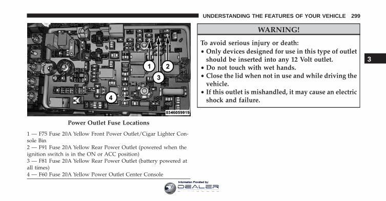
WARNING!
To avoid serious injury or death:• Only devices designed for use in this type of outlet
should be inserted into any 12 Volt outlet.• Do not touch with wet hands.• Close the lid when not in use and while driving the
vehicle.• If this outlet is mishandled, it may cause an electric
shock and failure.
Power Outlet Fuse Locations
1 — F75 Fuse 20A Yellow Front Power Outlet/Cigar Lighter Con-sole Bin2 — F91 Fuse 20A Yellow Rear Power Outlet (powered when theignition switch is in the ON or ACC position)3 — F81 Fuse 20A Yellow Rear Power Outlet (battery powered atall times)4 — F60 Fuse 20A Yellow Power Outlet Center Console
3
UNDERSTANDING THE FEATURES OF YOUR VEHICLE 299
Information Provided by:
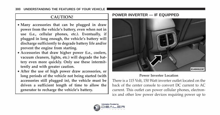
CAUTION!
• Many accessories that can be plugged in drawpower from the vehicle’s battery, even when not inuse (i.e., cellular phones, etc.). Eventually, ifplugged in long enough, the vehicle’s battery willdischarge sufficiently to degrade battery life and/orprevent the engine from starting.
• Accessories that draw higher power (i.e., coolers,vacuum cleaners, lights, etc.) will degrade the bat-tery even more quickly. Only use these intermit-tently and with greater caution.
• After the use of high power draw accessories, orlong periods of the vehicle not being started (withaccessories still plugged in), the vehicle must bedriven a sufficient length of time to allow thegenerator to recharge the vehicle’s battery.
POWER INVERTER — IF EQUIPPED
There is a 115 Volt, 150 Watt inverter outlet located on theback of the center console to convert DC current to ACcurrent. This outlet can power cellular phones, electron-ics and other low power devices requiring power up to
Power Inverter Location
300 UNDERSTANDING THE FEATURES OF YOUR VEHICLE
Information Provided by:
150 Watts. Certain high-end game consoles will exceedthis power limit, as will most power tools.
To turn on the power inverter outlet, simply plug in thedevice. The outlet automatically turns off when thedevice is unplugged.
The power inverter is designed with built-in overloadprotection. If the power rating of 150 Watts is exceeded,the power inverter will automatically shut down. Oncethe electrical device has been removed from the outlet theinverter should automatically reset. To avoid overloadingthe circuit, check the power ratings on electrical devicesprior to using the invertexr.
WARNING!
To avoid serious injury or death:• Do not insert any objects into the receptacles.• Do not touch with wet hands.• Close the lid when not in use.• If this outlet is mishandled, it may cause an electric
shock and failure.
3
UNDERSTANDING THE FEATURES OF YOUR VEHICLE 301
Information Provided by:
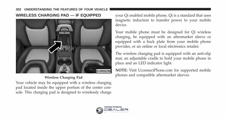
WIRELESS CHARGING PAD — IF EQUIPPED
Your vehicle may be equipped with a wireless chargingpad located inside the upper portion of the center con-sole. This charging pad is designed to wirelessly charge
your Qi enabled mobile phone. Qi is a standard that usesmagnetic induction to transfer power to your mobiledevice.
Your mobile phone must be designed for Qi wirelesscharging, be equipped with an aftermarket sleeve orequipped with a back plate from your mobile phoneprovider, or an online or local electronics retailer.
The wireless charging pad is equipped with an anti-slipmat, an adjustable cradle to hold your mobile phone inplace and an LED indicator light.
NOTE: Visit UconnectPhone.com for supported mobilephones and compatible aftermarket sleeves.
Wireless Charging Pad
302 UNDERSTANDING THE FEATURES OF YOUR VEHICLE
Information Provided by:
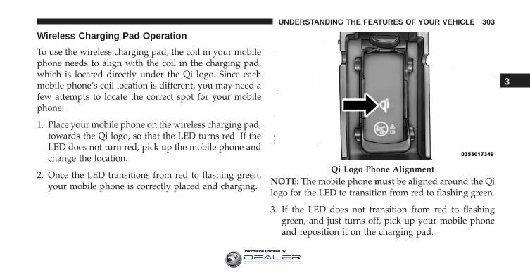
Wireless Charging Pad Operation
To use the wireless charging pad, the coil in your mobilephone needs to align with the coil in the charging pad,which is located directly under the Qi logo. Since eachmobile phone’s coil location is different, you may need afew attempts to locate the correct spot for your mobilephone:
1. Place your mobile phone on the wireless charging pad,towards the Qi logo, so that the LED turns red. If theLED does not turn red, pick up the mobile phone andchange the location.
2. Once the LED transitions from red to flashing green,your mobile phone is correctly placed and charging. NOTE: The mobile phone must be aligned around the Qi
logo for the LED to transition from red to flashing green.
3. If the LED does not transition from red to flashinggreen, and just turns off, pick up your mobile phoneand reposition it on the charging pad.
Qi Logo Phone Alignment
3
UNDERSTANDING THE FEATURES OF YOUR VEHICLE 303
Information Provided by:
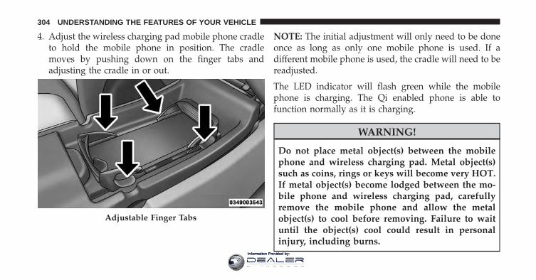
4. Adjust the wireless charging pad mobile phone cradleto hold the mobile phone in position. The cradlemoves by pushing down on the finger tabs andadjusting the cradle in or out.
NOTE: The initial adjustment will only need to be doneonce as long as only one mobile phone is used. If adifferent mobile phone is used, the cradle will need to bereadjusted.
The LED indicator will flash green while the mobilephone is charging. The Qi enabled phone is able tofunction normally as it is charging.
WARNING!
Do not place metal object(s) between the mobilephone and wireless charging pad. Metal object(s)such as coins, rings or keys will become very HOT.If metal object(s) become lodged between the mo-bile phone and wireless charging pad, carefullyremove the mobile phone and allow the metalobject(s) to cool before removing. Failure to waituntil the object(s) cool could result in personalinjury, including burns.
Adjustable Finger Tabs
304 UNDERSTANDING THE FEATURES OF YOUR VEHICLE
Information Provided by:
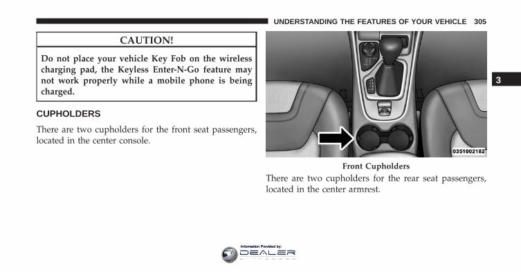
CAUTION!
Do not place your vehicle Key Fob on the wirelesscharging pad, the Keyless Enter-N-Go feature maynot work properly while a mobile phone is beingcharged.
CUPHOLDERS
There are two cupholders for the front seat passengers,located in the center console.
There are two cupholders for the rear seat passengers,located in the center armrest.
Front Cupholders
3
UNDERSTANDING THE FEATURES OF YOUR VEHICLE 305
Information Provided by:
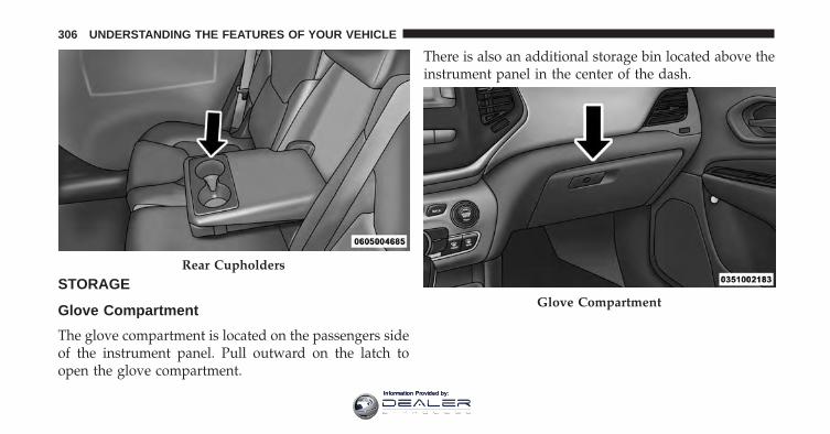
STORAGE
Glove Compartment
The glove compartment is located on the passengers sideof the instrument panel. Pull outward on the latch toopen the glove compartment.
There is also an additional storage bin located above theinstrument panel in the center of the dash.
Rear Cupholders
Glove Compartment
306 UNDERSTANDING THE FEATURES OF YOUR VEHICLE
Information Provided by:
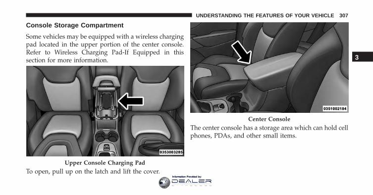
Console Storage Compartment
Some vehicles may be equipped with a wireless chargingpad located in the upper portion of the center console.Refer to Wireless Charging Pad-If Equipped in thissection for more information.
To open, pull up on the latch and lift the cover.
The center console has a storage area which can hold cellphones, PDAs, and other small items.
Upper Console Charging Pad
Center Console
3
UNDERSTANDING THE FEATURES OF YOUR VEHICLE 307
Information Provided by:
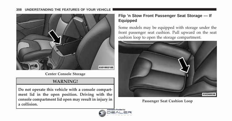
WARNING!
Do not operate this vehicle with a console compart-ment lid in the open position. Driving with theconsole compartment lid open may result in injury ina collision.
Flip ’n Stow Front Passenger Seat Storage — IfEquipped
Some models may be equipped with storage under thefront passenger seat cushion. Pull upward on the seatcushion loop to open the storage compartment.
Center Console Storage
Passenger Seat Cushion Loop
308 UNDERSTANDING THE FEATURES OF YOUR VEHICLE
Information Provided by:
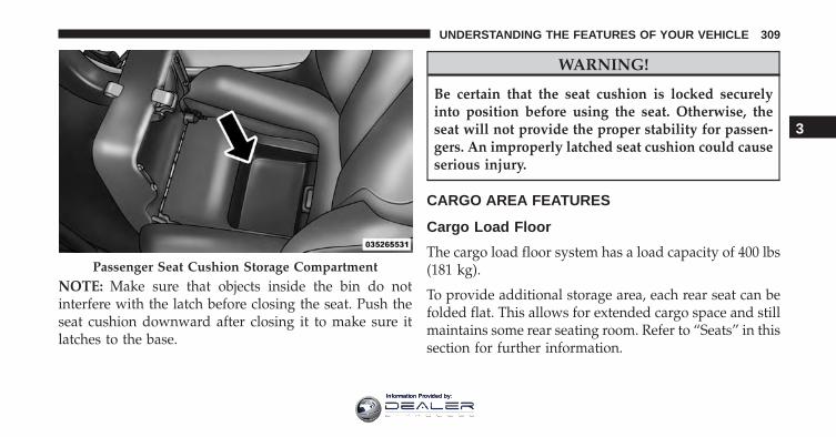
NOTE: Make sure that objects inside the bin do notinterfere with the latch before closing the seat. Push theseat cushion downward after closing it to make sure itlatches to the base.
WARNING!
Be certain that the seat cushion is locked securelyinto position before using the seat. Otherwise, theseat will not provide the proper stability for passen-gers. An improperly latched seat cushion could causeserious injury.
CARGO AREA FEATURES
Cargo Load Floor
The cargo load floor system has a load capacity of 400 lbs(181 kg).
To provide additional storage area, each rear seat can befolded flat. This allows for extended cargo space and stillmaintains some rear seating room. Refer to “Seats” in thissection for further information.
Passenger Seat Cushion Storage Compartment
3
UNDERSTANDING THE FEATURES OF YOUR VEHICLE 309
Information Provided by:
Cargo Extension Panels
Cargo extension panels can be folded and unfolded.When the rear seats are moved to the more forwardpositions and the rear seat backs are folded down, theextension panels can be unfolded manually by hand (2 ofthem). The extension panels can be used to extend theload floor to the rear seats and/or hide the gap betweenthe load floor and rear seats, or to assist in loading largeitems into the cargo area.
Cargo Tie-Down Hooks And Loops
The tie-downs located on the cargo area floor should beused to secure loads safely when the vehicle is moving.
Cargo tie-down loops are located on the trim panels.
WARNING!
• Cargo tie-downs are not safe anchors for a childseat tether strap. In a sudden stop or accident, atie-down could pull loose and allow the child seatto come loose. A child could be badly injured. Useonly the anchors provided for child seat tethers.
• To help protect against personal injury, passengersshould not be seated in the rear cargo area. The rearcargo space is intended for load carrying purposesonly, not for passengers, who should sit in seatsand use seat belts.
WARNING!
The weight and position of cargo and passengers canchange the vehicle center of gravity and vehicle
(Continued)
310 UNDERSTANDING THE FEATURES OF YOUR VEHICLE
Information Provided by:
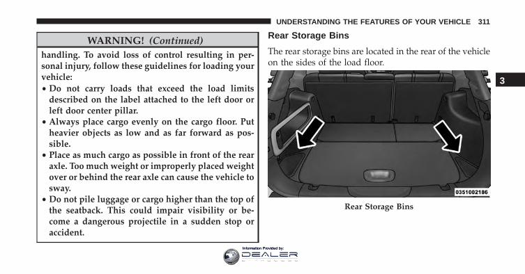
WARNING! (Continued)handling. To avoid loss of control resulting in per-sonal injury, follow these guidelines for loading yourvehicle:• Do not carry loads that exceed the load limits
described on the label attached to the left door orleft door center pillar.
• Always place cargo evenly on the cargo floor. Putheavier objects as low and as far forward as pos-sible.
• Place as much cargo as possible in front of the rearaxle. Too much weight or improperly placed weightover or behind the rear axle can cause the vehicle tosway.
• Do not pile luggage or cargo higher than the top ofthe seatback. This could impair visibility or be-come a dangerous projectile in a sudden stop oraccident.
Rear Storage Bins
The rear storage bins are located in the rear of the vehicleon the sides of the load floor.
Rear Storage Bins
3
UNDERSTANDING THE FEATURES OF YOUR VEHICLE 311
Information Provided by:
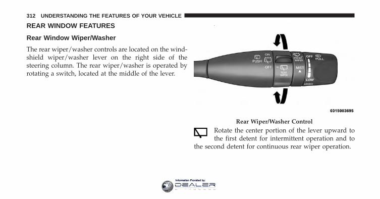
REAR WINDOW FEATURES
Rear Window Wiper/Washer
The rear wiper/washer controls are located on the wind-shield wiper/washer lever on the right side of thesteering column. The rear wiper/washer is operated byrotating a switch, located at the middle of the lever.
Rotate the center portion of the lever upward tothe first detent for intermittent operation and to
the second detent for continuous rear wiper operation.
Rear Wiper/Washer Control
312 UNDERSTANDING THE FEATURES OF YOUR VEHICLE
Information Provided by:
To use the washer, push the lever forward andhold while spray is desired. If the lever ispushed while in the intermittent setting, thewiper will turn on and operate for several wipe
cycles after the end of the lever is released, and thenresume the intermittent interval previously selected.
If the lever is pushed while the wiper is in the offposition, the wiper will operate for several wipe cycles,then turn off.
NOTE: As a protective measure, the pump will stop ifthe switch is held for more than 20 seconds. Once thelever is released the pump will resume normal operation.
If the rear wiper is operating when the ignition is turnedOFF, the wiper will automatically return to the “park”position.
Rear Window Defroster
The rear window defroster button is located onthe switch bank by the manual climate controls.
Push this button to turn on the rear window defrosterand the heated outside mirrors. An indicator in thebutton will illuminate when the rear window defroster ison. The rear window defroster automatically turns offafter approximately 10 minutes. For an additional fiveminutes of operation, push the button a second time.
NOTE:
• The Windshield Wiper De-Icer (if equipped) shall beactivated automatically when the Rear Defrost isturned on and when the ambient temperature is below33 degrees F (0.6° C).
• To prevent excessive battery drain, use the rear win-dow defroster only when the engine is operating.
3
UNDERSTANDING THE FEATURES OF YOUR VEHICLE 313
Information Provided by:
CAUTION!
Failure to follow these cautions can cause damage tothe heating elements:• Use care when washing the inside of the rear
window. Do not use abrasive window cleaners onthe interior surface of the window. Use a soft clothand a mild washing solution, wiping parallel to theheating elements. Labels can be peeled off aftersoaking with warm water.
• Do not use scrapers, sharp instruments, or abrasivewindow cleaners on the interior surface of thewindow.
• Keep all objects a safe distance from the window.
ROOF LUGGAGE RACK — IF EQUIPPED
The load carried on the roof, when equipped with aluggage rack, must not exceed 150 lbs (68 kg), and itshould be uniformly distributed over the cargo area.
Crossbars should always be used whenever cargo isplaced on the roof rack. Check the straps frequently to besure that the load remains securely attached.
NOTE: Crossbars can be purchased at an authorizeddealer through Mopar parts.
External racks do not increase the total load carryingcapacity of the vehicle. Be sure that the total occupantand luggage load inside the vehicle, plus the load on theluggage rack, do not exceed the maximum vehicle loadcapacity.
314 UNDERSTANDING THE FEATURES OF YOUR VEHICLE
Information Provided by:
CAUTION!
• To avoid damage to the roof rack and vehicle, donot exceed the maximum roof rack load capacity.Always distribute heavy loads as evenly as pos-sible and secure the load appropriately.
• Long loads, which extend over the windshield,such as wood panels or surfboards, should besecured to both the front and rear of the vehicle.
• Place a blanket or other protection between thesurface of the roof and the load.
• Travel at reduced speeds and turn corners carefullywhen carrying large or heavy loads on the roofrack. Wind forces, due to natural causes or nearbytruck traffic, can add sudden upward loads. This isespecially true on large flat loads and may result indamage to the cargo or your vehicle.
WARNING!
Cargo must be securely tied down before drivingyour vehicle. Improperly secured loads can fly off thevehicle, particularly at high speeds, resulting in per-sonal injury or property damage. Follow the roof rackcautions when carrying cargo on your roof rack.
3
UNDERSTANDING THE FEATURES OF YOUR VEHICLE 315
Information Provided by:

Information Provided by:
UNDERSTANDING YOUR INSTRUMENT PANEL
CONTENTS� INSTRUMENT PANEL FEATURES . . . . . . . . . .320
� INSTRUMENT CLUSTER — BASE . . . . . . . . . .321
� INSTRUMENT CLUSTER — PREMIUM . . . . . .324
� WARNING AND INDICATOR LIGHTS . . . . . . .326
▫ Red Telltale Indicator Lights . . . . . . . . . . . . . .327
▫ Yellow Telltale Indicator Lights . . . . . . . . . . . .337
▫ Green Telltale Indicator Lights . . . . . . . . . . . .354
▫ White Telltale Indicator Light . . . . . . . . . . . . .357
▫ Blue Telltale Indicator Light . . . . . . . . . . . . . .360
� ELECTRONIC VEHICLE INFORMATION CENTER(EVIC) . . . . . . . . . . . . . . . . . . . . . . . . . . . . . .361
▫ Oil Change Reset . . . . . . . . . . . . . . . . . . . . .363
▫ EVIC Selectable Menu Items . . . . . . . . . . . . .364
� DRIVER INFORMATION DISPLAY (DID) . . . . .370
▫ Oil Change Reset . . . . . . . . . . . . . . . . . . . . .372
▫ DID Selectable Menu Items . . . . . . . . . . . . . .373
� UCONNECT SETTINGS . . . . . . . . . . . . . . . . . .379
▫ Buttons On The Faceplate. . . . . . . . . . . . . . . .380
▫ Buttons On The Touchscreen. . . . . . . . . . . . . .381
4
Information Provided by:
▫ Customer Programmable Features/PersonalSettings — Uconnect 5.0 Settings. . . . . . . . . . .381
▫ Customer Programmable Features/PersonalSettings — Uconnect 8.4 Personal Settings . . . .398
� UCONNECT RADIOS — IF EQUIPPED . . . . . .415
� MEDIA HUB — IF EQUIPPED . . . . . . . . . . . . .416
� STEERING WHEEL AUDIO CONTROLS — IFEQUIPPED . . . . . . . . . . . . . . . . . . . . . . . . . . .416
▫ Radio Operation . . . . . . . . . . . . . . . . . . . . . .417
▫ CD Player . . . . . . . . . . . . . . . . . . . . . . . . . . .418
� CD/DVD DISC MAINTENANCE . . . . . . . . . . .418
� RADIO OPERATION AND MOBILE DEVICES . .419
▫ Regulatory And Safety Information . . . . . . . . .419
� CLIMATE CONTROLS . . . . . . . . . . . . . . . . . . .421
▫ Manual Climate Controls WithoutTouchscreen — If Equipped . . . . . . . . . . . . . .421
▫ Manual Climate Controls WithTouchscreen — If Equipped . . . . . . . . . . . . . .426
▫ Windshield Wiper De-icer — If Equipped . . . .431
▫ Dual Zone Automatic Climate Controls WithTouchscreen — If Equipped . . . . . . . . . . . . . .432
▫ Climate Control Functions . . . . . . . . . . . . . . .439
▫ Automatic Temperature Control (ATC) . . . . . .441
▫ Operating Tips . . . . . . . . . . . . . . . . . . . . . . .442
� PERSONALIZED MENU BAR . . . . . . . . . . . . .446
� UCONNECT VOICE RECOGNITION QUICKTIPS . . . . . . . . . . . . . . . . . . . . . . . . . . . . . . . .446
▫ Introducing Uconnect. . . . . . . . . . . . . . . . . . .446
318 UNDERSTANDING YOUR INSTRUMENT PANEL
Information Provided by:
▫ Get Started . . . . . . . . . . . . . . . . . . . . . . . . . .447
▫ Basic Voice Commands. . . . . . . . . . . . . . . . . .449
▫ Radio . . . . . . . . . . . . . . . . . . . . . . . . . . . . . .450
▫ Media. . . . . . . . . . . . . . . . . . . . . . . . . . . . . .451
▫ Phone. . . . . . . . . . . . . . . . . . . . . . . . . . . . . .453
▫ Voice Text Reply . . . . . . . . . . . . . . . . . . . . . .455
▫ Climate (8.4A/8.4AN) . . . . . . . . . . . . . . . . . .457
▫ Navigation (8.4A/8.4AN) . . . . . . . . . . . . . . . .457
▫ Uconnect Access (8.4A/8.4AN) . . . . . . . . . . . .459
▫ Register (8.4A/8.4AN) . . . . . . . . . . . . . . . . . .460
▫ Mobile App (8.4A/8.4AN) . . . . . . . . . . . . . . .460
▫ Voice Texting (8.4A/8.4AN) . . . . . . . . . . . . . .462
▫ Yelp (8.4A/8.4AN) . . . . . . . . . . . . . . . . . . . . .463
▫ SiriusXM Travel Link (8.4A/8.4AN). . . . . . . . .464
▫ Siri Eyes Free — If Equipped . . . . . . . . . . . . .465
▫ Do Not Disturb . . . . . . . . . . . . . . . . . . . . . .466
▫ General Information . . . . . . . . . . . . . . . . . . .466
▫ Additional Information . . . . . . . . . . . . . . . . .467
4
UNDERSTANDING YOUR INSTRUMENT PANEL 319
Information Provided by:
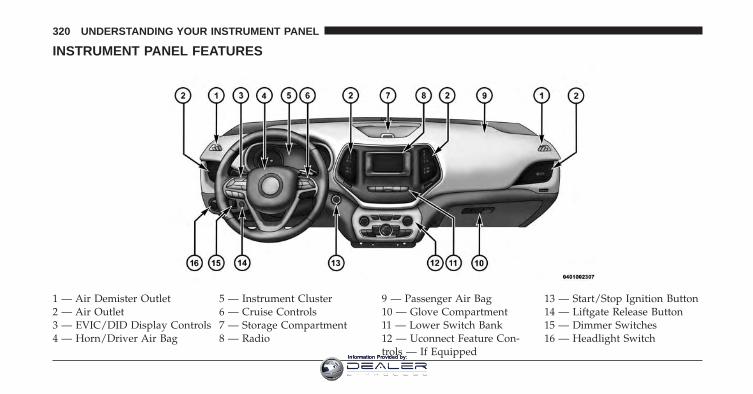
INSTRUMENT PANEL FEATURES
1 — Air Demister Outlet 5 — Instrument Cluster 9 — Passenger Air Bag 13 — Start/Stop Ignition Button2 — Air Outlet 6 — Cruise Controls 10 — Glove Compartment 14 — Liftgate Release Button3 — EVIC/DID Display Controls 7 — Storage Compartment 11 — Lower Switch Bank 15 — Dimmer Switches4 — Horn/Driver Air Bag 8 — Radio 12 — Uconnect Feature Con-
trols — If Equipped16 — Headlight Switch
320 UNDERSTANDING YOUR INSTRUMENT PANEL
Information Provided by:
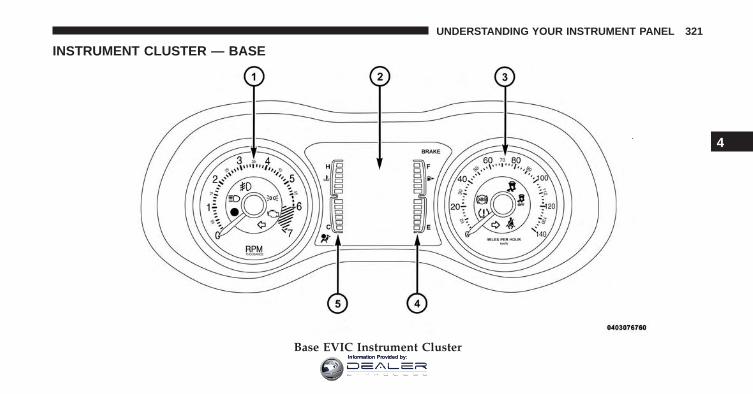
INSTRUMENT CLUSTER — BASE
Base EVIC Instrument Cluster
4
UNDERSTANDING YOUR INSTRUMENT PANEL 321
Information Provided by:
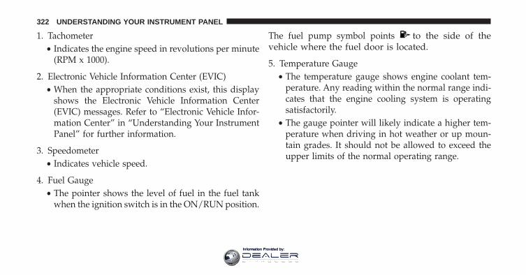
1. Tachometer• Indicates the engine speed in revolutions per minute
(RPM x 1000).
2. Electronic Vehicle Information Center (EVIC)• When the appropriate conditions exist, this display
shows the Electronic Vehicle Information Center(EVIC) messages. Refer to “Electronic Vehicle Infor-mation Center” in “Understanding Your InstrumentPanel” for further information.
3. Speedometer• Indicates vehicle speed.
4. Fuel Gauge• The pointer shows the level of fuel in the fuel tank
when the ignition switch is in the ON/RUN position.
The fuel pump symbol points to the side of thevehicle where the fuel door is located.
5. Temperature Gauge• The temperature gauge shows engine coolant tem-
perature. Any reading within the normal range indi-cates that the engine cooling system is operatingsatisfactorily.
• The gauge pointer will likely indicate a higher tem-perature when driving in hot weather or up moun-tain grades. It should not be allowed to exceed theupper limits of the normal operating range.
322 UNDERSTANDING YOUR INSTRUMENT PANEL
Information Provided by:
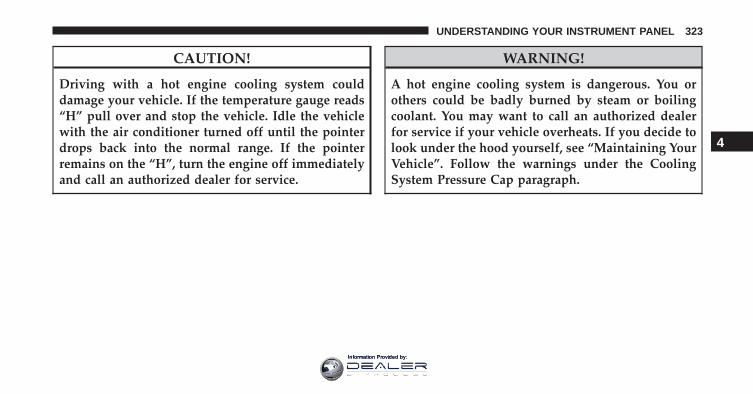
CAUTION!
Driving with a hot engine cooling system coulddamage your vehicle. If the temperature gauge reads“H” pull over and stop the vehicle. Idle the vehiclewith the air conditioner turned off until the pointerdrops back into the normal range. If the pointerremains on the “H”, turn the engine off immediatelyand call an authorized dealer for service.
WARNING!
A hot engine cooling system is dangerous. You orothers could be badly burned by steam or boilingcoolant. You may want to call an authorized dealerfor service if your vehicle overheats. If you decide tolook under the hood yourself, see “Maintaining YourVehicle”. Follow the warnings under the CoolingSystem Pressure Cap paragraph.
4
UNDERSTANDING YOUR INSTRUMENT PANEL 323
Information Provided by:
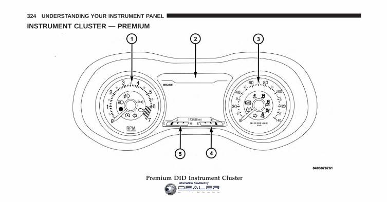
INSTRUMENT CLUSTER — PREMIUM
Premium DID Instrument Cluster
324 UNDERSTANDING YOUR INSTRUMENT PANEL
Information Provided by:
1. Tachometer• Indicates the engine speed in revolutions per minute
(RPM x 1000).
2. Driver Information Display (DID)• When the appropriate conditions exist, this display
shows the Driver Information Display (DID) mes-sages. Refer to “Driver Information Display (DID)”in “Understanding Your Instrument Panel” for fur-ther information.
3. Speedometer• Indicates vehicle speed.
4. Fuel Gauge• The pointer shows the level of fuel in the fuel tank
when the ignition switch is in the ON/RUN position.
The fuel pump symbol points to the side of thevehicle where the fuel door is located.
5. Temperature Gauge• The temperature gauge shows engine coolant tem-
perature. Any reading within the normal range indi-cates that the engine cooling system is operatingsatisfactorily.
• The gauge pointer will likely indicate a higher tem-perature when driving in hot weather or up moun-tain grades. It should not be allowed to exceed theupper limits of the normal operating range.
4
UNDERSTANDING YOUR INSTRUMENT PANEL 325
Information Provided by:
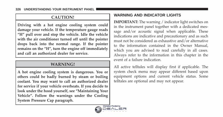
CAUTION!
Driving with a hot engine cooling system coulddamage your vehicle. If the temperature gauge reads“H” pull over and stop the vehicle. Idle the vehiclewith the air conditioner turned off until the pointerdrops back into the normal range. If the pointerremains on the “H”, turn the engine off immediatelyand call an authorized dealer for service.
WARNING!
A hot engine cooling system is dangerous. You orothers could be badly burned by steam or boilingcoolant. You may want to call an authorized dealerfor service if your vehicle overheats. If you decide tolook under the hood yourself, see “Maintaining YourVehicle”. Follow the warnings under the CoolingSystem Pressure Cap paragraph.
WARNING AND INDICATOR LIGHTS
IMPORTANT: The warning / indicator light switches onin the instrument panel together with a dedicated mes-sage and/or acoustic signal when applicable. Theseindications are indicative and precautionary and as suchmust not be considered as exhaustive and/or alternativeto the information contained in the Owner Manual,which you are advised to read carefully in all cases.Always refer to the information in this chapter in theevent of a failure indication.
All active telltales will display first if applicable. Thesystem check menu may appear different based uponequipment options and current vehicle status. Sometelltales are optional and may not appear.
326 UNDERSTANDING YOUR INSTRUMENT PANEL
Information Provided by:
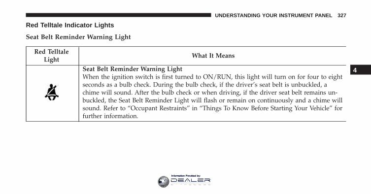
Red Telltale Indicator Lights
Seat Belt Reminder Warning Light
Red TelltaleLight
What It Means
Seat Belt Reminder Warning LightWhen the ignition switch is first turned to ON/RUN, this light will turn on for four to eightseconds as a bulb check. During the bulb check, if the driver’s seat belt is unbuckled, achime will sound. After the bulb check or when driving, if the driver seat belt remains un-buckled, the Seat Belt Reminder Light will flash or remain on continuously and a chime willsound. Refer to “Occupant Restraints” in “Things To Know Before Starting Your Vehicle” forfurther information.
4
UNDERSTANDING YOUR INSTRUMENT PANEL 327
Information Provided by:
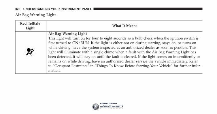
Air Bag Warning Light
Red TelltaleLight
What It Means
Air Bag Warning LightThis light will turn on for four to eight seconds as a bulb check when the ignition switch isfirst turned to ON/RUN. If the light is either not on during starting, stays on, or turns onwhile driving, have the system inspected at an authorized dealer as soon as possible. Thislight will illuminate with a single chime when a fault with the Air Bag Warning Light hasbeen detected, it will stay on until the fault is cleared. If the light comes on intermittently orremains on while driving, have an authorized dealer service the vehicle immediately. Referto “Occupant Restraints” in “Things To Know Before Starting Your Vehicle” for further infor-mation.
328 UNDERSTANDING YOUR INSTRUMENT PANEL
Information Provided by:
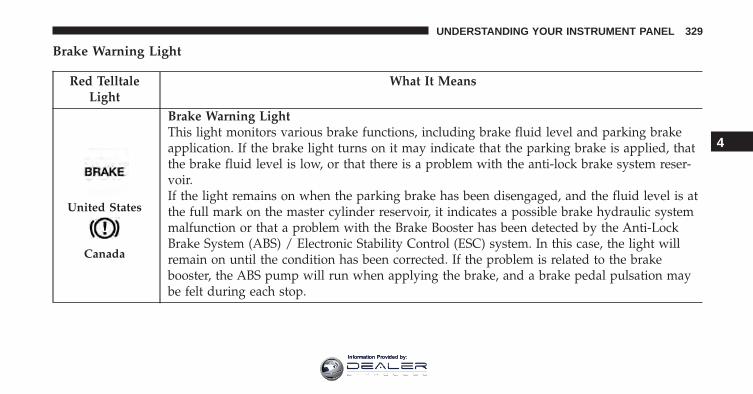
Brake Warning Light
Red TelltaleLight
What It Means
United States
Canada
Brake Warning LightThis light monitors various brake functions, including brake fluid level and parking brakeapplication. If the brake light turns on it may indicate that the parking brake is applied, thatthe brake fluid level is low, or that there is a problem with the anti-lock brake system reser-voir.If the light remains on when the parking brake has been disengaged, and the fluid level is atthe full mark on the master cylinder reservoir, it indicates a possible brake hydraulic systemmalfunction or that a problem with the Brake Booster has been detected by the Anti-LockBrake System (ABS) / Electronic Stability Control (ESC) system. In this case, the light willremain on until the condition has been corrected. If the problem is related to the brakebooster, the ABS pump will run when applying the brake, and a brake pedal pulsation maybe felt during each stop.
4
UNDERSTANDING YOUR INSTRUMENT PANEL 329
Information Provided by:
The dual brake system provides a reserve braking capac-ity in the event of a failure to a portion of the hydraulicsystem. A leak in either half of the dual brake system isindicated by the Brake Warning Light, which will turn onwhen the brake fluid level in the master cylinder hasdropped below a specified level.
The light will remain on until the cause is corrected.
NOTE: The light may flash momentarily during sharpcornering maneuvers, which change fluid level condi-tions. The vehicle should have service performed, andthe brake fluid level checked.
If brake failure is indicated, immediate repair is necessary.
WARNING!
Driving a vehicle with the red brake light on isdangerous. Part of the brake system may have failed.It will take longer to stop the vehicle. You could havea collision. Have the vehicle checked immediately.
Vehicles equipped with the Anti-Lock Brake System(ABS) are also equipped with Electronic Brake ForceDistribution (EBD). In the event of an EBD failure, theBrake Warning Light will turn on along with the ABSLight. Immediate repair to the ABS system is required.
330 UNDERSTANDING YOUR INSTRUMENT PANEL
Information Provided by:
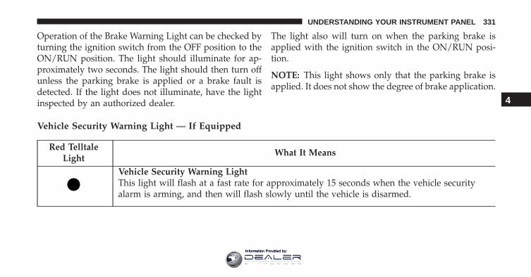
Operation of the Brake Warning Light can be checked byturning the ignition switch from the OFF position to theON/RUN position. The light should illuminate for ap-proximately two seconds. The light should then turn offunless the parking brake is applied or a brake fault isdetected. If the light does not illuminate, have the lightinspected by an authorized dealer.
The light also will turn on when the parking brake isapplied with the ignition switch in the ON/RUN posi-tion.
NOTE: This light shows only that the parking brake isapplied. It does not show the degree of brake application.
Vehicle Security Warning Light — If Equipped
Red TelltaleLight
What It Means
Vehicle Security Warning LightThis light will flash at a fast rate for approximately 15 seconds when the vehicle securityalarm is arming, and then will flash slowly until the vehicle is disarmed.
4
UNDERSTANDING YOUR INSTRUMENT PANEL 331
Information Provided by:
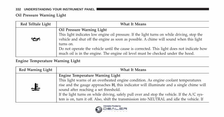
Oil Pressure Warning Light
Red Telltale Light What It MeansOil Pressure Warning LightThis light indicates low engine oil pressure. If the light turns on while driving, stop thevehicle and shut off the engine as soon as possible. A chime will sound when this lightturns on.Do not operate the vehicle until the cause is corrected. This light does not indicate howmuch oil is in the engine. The engine oil level must be checked under the hood.
Engine Temperature Warning Light
Red Warning Light What It MeansEngine Temperature Warning LightThis light warns of an overheated engine condition. As engine coolant temperaturesrise and the gauge approaches H, this indicator will illuminate and a single chime willsound after reaching a set threshold.If the light turns on while driving, safely pull over and stop the vehicle. If the A/C sys-tem is on, turn it off. Also, shift the transmission into NEUTRAL and idle the vehicle. If
332 UNDERSTANDING YOUR INSTRUMENT PANEL
Information Provided by:
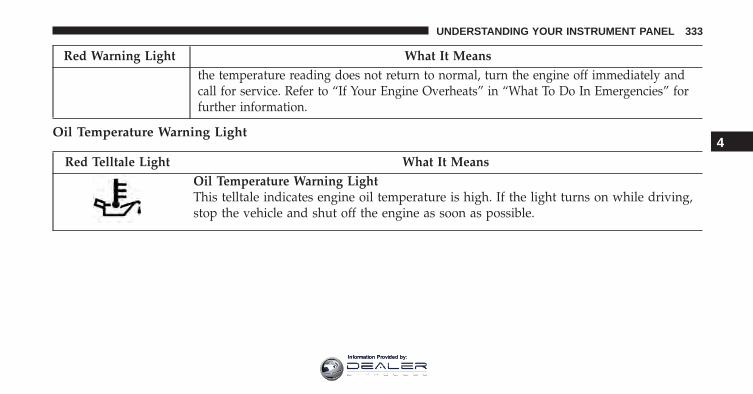
Red Warning Light What It Meansthe temperature reading does not return to normal, turn the engine off immediately andcall for service. Refer to “If Your Engine Overheats” in “What To Do In Emergencies” forfurther information.
Oil Temperature Warning Light
Red Telltale Light What It MeansOil Temperature Warning LightThis telltale indicates engine oil temperature is high. If the light turns on while driving,stop the vehicle and shut off the engine as soon as possible.
4
UNDERSTANDING YOUR INSTRUMENT PANEL 333
Information Provided by:
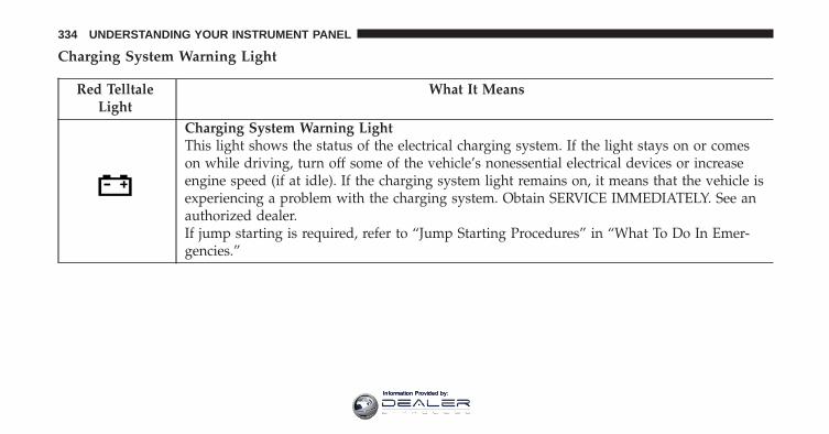
Charging System Warning Light
Red TelltaleLight
What It Means
Charging System Warning LightThis light shows the status of the electrical charging system. If the light stays on or comeson while driving, turn off some of the vehicle’s nonessential electrical devices or increaseengine speed (if at idle). If the charging system light remains on, it means that the vehicle isexperiencing a problem with the charging system. Obtain SERVICE IMMEDIATELY. See anauthorized dealer.If jump starting is required, refer to “Jump Starting Procedures” in “What To Do In Emer-gencies.”
334 UNDERSTANDING YOUR INSTRUMENT PANEL
Information Provided by:
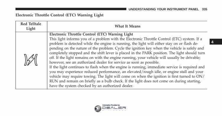
Electronic Throttle Control (ETC) Warning Light
Red TelltaleLight
What It Means
Electronic Throttle Control (ETC) Warning LightThis light informs you of a problem with the Electronic Throttle Control (ETC) system. If aproblem is detected while the engine is running, the light will either stay on or flash de-pending on the nature of the problem. Cycle the ignition key when the vehicle is safely andcompletely stopped and the shift lever is placed in the PARK position. The light should turnoff. If the light remains on with the engine running, your vehicle will usually be drivable;however, see an authorized dealer for service as soon as possible.If the light continues to flash when the engine is running, immediate service is required andyou may experience reduced performance, an elevated/rough idle, or engine stall and yourvehicle may require towing. The light will come on when the ignition is first turned to ON/RUN and remain on briefly as a bulb check. If the light does not come on during starting,have the system checked by an authorized dealer.
4
UNDERSTANDING YOUR INSTRUMENT PANEL 335
Information Provided by:
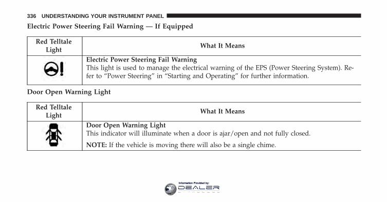
Electric Power Steering Fail Warning — If Equipped
Red TelltaleLight
What It Means
Electric Power Steering Fail WarningThis light is used to manage the electrical warning of the EPS (Power Steering System). Re-fer to “Power Steering” in “Starting and Operating” for further information.
Door Open Warning Light
Red TelltaleLight
What It Means
Door Open Warning LightThis indicator will illuminate when a door is ajar/open and not fully closed.
NOTE: If the vehicle is moving there will also be a single chime.
336 UNDERSTANDING YOUR INSTRUMENT PANEL
Information Provided by:
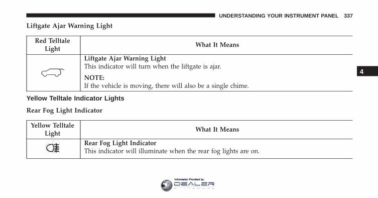
Liftgate Ajar Warning Light
Red TelltaleLight
What It Means
Liftgate Ajar Warning LightThis indicator will turn when the liftgate is ajar.
NOTE:If the vehicle is moving, there will also be a single chime.
Yellow Telltale Indicator Lights
Rear Fog Light Indicator
Yellow TelltaleLight
What It Means
Rear Fog Light IndicatorThis indicator will illuminate when the rear fog lights are on.
4
UNDERSTANDING YOUR INSTRUMENT PANEL 337
Information Provided by:
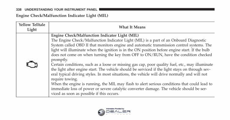
Engine Check/Malfunction Indicator Light (MIL)
Yellow TelltaleLight
What It Means
Engine Check/Malfunction Indicator Light (MIL)The Engine Check/Malfunction Indicator Light (MIL) is a part of an Onboard DiagnosticSystem called OBD II that monitors engine and automatic transmission control systems. Thelight will illuminate when the ignition is in the ON position before engine start. If the bulbdoes not come on when turning the key from OFF to ON/RUN, have the condition checkedpromptly.Certain conditions, such as a loose or missing gas cap, poor quality fuel, etc., may illuminatethe light after engine start. The vehicle should be serviced if the light stays on through sev-eral typical driving styles. In most situations, the vehicle will drive normally and will notrequire towing.When the engine is running, the MIL may flash to alert serious conditions that could lead toimmediate loss of power or severe catalytic converter damage. The vehicle should be ser-viced as soon as possible if this occurs.
338 UNDERSTANDING YOUR INSTRUMENT PANEL
Information Provided by:
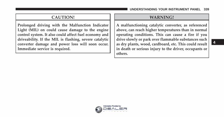
CAUTION!
Prolonged driving with the Malfunction IndicatorLight (MIL) on could cause damage to the enginecontrol system. It also could affect fuel economy anddriveability. If the MIL is flashing, severe catalyticconverter damage and power loss will soon occur.Immediate service is required.
WARNING!
A malfunctioning catalytic converter, as referencedabove, can reach higher temperatures than in normaloperating conditions. This can cause a fire if youdrive slowly or park over flammable substances suchas dry plants, wood, cardboard, etc. This could resultin death or serious injury to the driver, occupants orothers.
4
UNDERSTANDING YOUR INSTRUMENT PANEL 339
Information Provided by:
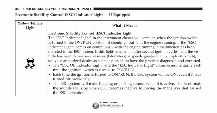
Electronic Stability Control (ESC) Indicator Light — If Equipped
Yellow TelltaleLight
What It Means
Electronic Stability Control (ESC) Indicator LightThe “ESC Indicator Light” in the instrument cluster will come on when the ignition switchis turned to the ON/RUN position. It should go out with the engine running. If the “ESCIndicator Light” comes on continuously with the engine running, a malfunction has beendetected in the ESC system. If this light remains on after several ignition cycles, and the ve-hicle has been driven several miles (kilometers) at speeds greater than 30 mph (48 km/h),see your authorized dealer as soon as possible to have the problem diagnosed and corrected.• The “ESC Off Indicator Light” and the “ESC Indicator Light” come on momentarily each
time the ignition switch is turned to ON/RUN.• Each time the ignition is turned to ON/RUN, the ESC system will be ON, even if it was
turned off previously.• The ESC system will make buzzing or clicking sounds when it is active. This is normal;
the sounds will stop when ESC becomes inactive following the maneuver that causedthe ESC activation.
340 UNDERSTANDING YOUR INSTRUMENT PANEL
Information Provided by:
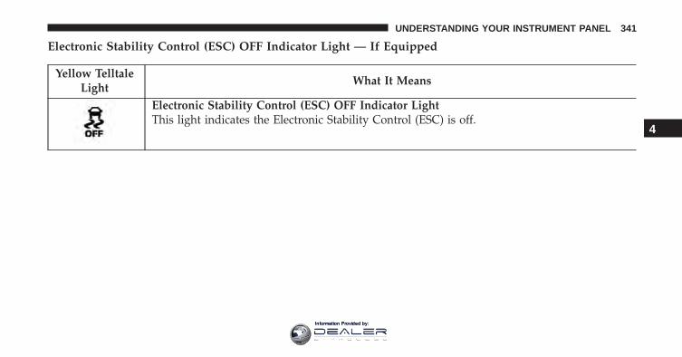
Electronic Stability Control (ESC) OFF Indicator Light — If Equipped
Yellow TelltaleLight
What It Means
Electronic Stability Control (ESC) OFF Indicator LightThis light indicates the Electronic Stability Control (ESC) is off.
4
UNDERSTANDING YOUR INSTRUMENT PANEL 341
Information Provided by:
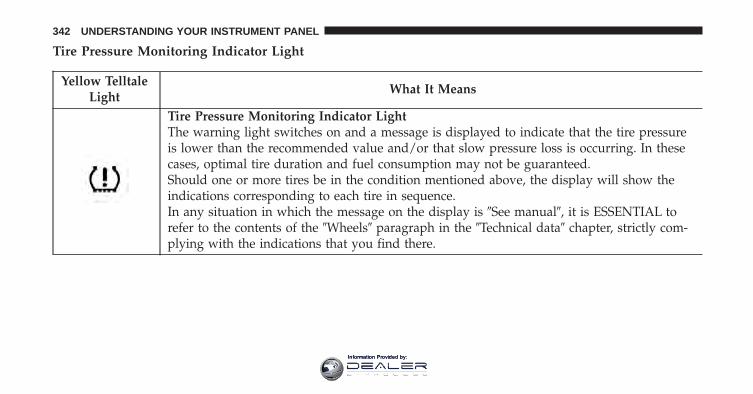
Tire Pressure Monitoring Indicator Light
Yellow TelltaleLight
What It Means
Tire Pressure Monitoring Indicator LightThe warning light switches on and a message is displayed to indicate that the tire pressureis lower than the recommended value and/or that slow pressure loss is occurring. In thesecases, optimal tire duration and fuel consumption may not be guaranteed.Should one or more tires be in the condition mentioned above, the display will show theindications corresponding to each tire in sequence.In any situation in which the message on the display is �See manual�, it is ESSENTIAL torefer to the contents of the �Wheels� paragraph in the �Technical data� chapter, strictly com-plying with the indications that you find there.
342 UNDERSTANDING YOUR INSTRUMENT PANEL
Information Provided by:
IMPORTANT: Do not continue driving with one or moreflat tires as handling may be compromised. Stop thevehicle, avoiding sharp braking and steering. Repairimmediately using the dedicated tire repair kit andcontact your authorized dealership as soon as possible.
Each tire, including the spare (if provided), should bechecked monthly when cold and inflated to the inflationpressure recommended by the vehicle manufacturer on thevehicle placard or tire inflation pressure label. If yourvehicle has tires of a different size than the size indicatedon the vehicle placard or tire inflation pressure label, youshould determine the proper tire inflation pressure forthose tires.
As an added safety feature, your vehicle has beenequipped with a Tire Pressure Monitoring System(TPMS) that illuminates a low tire pressure telltale whenone or more of your tires is significantly under-inflated.Accordingly, when the low tire pressure telltale illumi-nates, you should stop and check your tires as soon as
possible and inflate them to the proper pressure. Drivingon a significantly under-inflated tire causes the tire tooverheat and can lead to tire failure. Under-inflation alsoreduces fuel efficiency and tire tread life, and may affectthe vehicle’s handling and stopping ability.
Please note that the TPMS is not a substitute for propertire maintenance, and it is the driver’s responsibility tomaintain correct tire pressure, even if under-inflation hasnot reached the level to trigger illumination of the TPMSlow tire pressure telltale.
Your vehicle has also been equipped with a TPMSmalfunction indicator to indicate when the system is notoperating properly. The TPMS malfunction indicator iscombined with the low tire pressure telltale. When thesystem detects a malfunction, the telltale will flash forapproximately one minute and then remain continuouslyilluminated. This sequence will continue upon subse-quent vehicle start-ups as long as the malfunction exists.
4
UNDERSTANDING YOUR INSTRUMENT PANEL 343
Information Provided by:
When the malfunction indicator is illuminated, the sys-tem may not be able to detect or signal low tire pressureas intended. TPMS malfunctions may occur for a varietyof reasons, including the installation of replacement oralternate tires or wheels on the vehicle that prevent theTPMS from functioning properly. Always check theTPMS malfunction telltale after replacing one or moretires or wheels on your vehicle, to ensure that thereplacement or alternate tires and wheels allow the TPMSto continue to function properly.
CAUTION!
The TPMS has been optimized for the originalequipment tires and wheels. TPMS pressures andwarning have been established for the tire size
(Continued)
CAUTION! (Continued)equipped on your vehicle. Undesirable system opera-tion or sensor damage may result when using re-placement equipment that is not of the same size,type, and/or style. Aftermarket wheels can causesensor damage. Using aftermarket tire sealants maycause the Tire Pressure Monitoring System (TPMS)sensor to become inoperable. After using an after-market tire sealant it is recommended that you takeyour vehicle to an authorized dealership to have yoursensor function checked.
344 UNDERSTANDING YOUR INSTRUMENT PANEL
Information Provided by:
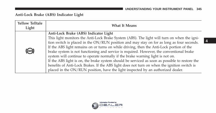
Anti-Lock Brake (ABS) Indicator Light
Yellow TelltaleLight
What It Means
Anti-Lock Brake (ABS) Indicator LightThis light monitors the Anti-Lock Brake System (ABS). The light will turn on when the igni-tion switch is placed in the ON/RUN position and may stay on for as long as four seconds.If the ABS light remains on or turns on while driving, then the Anti-Lock portion of thebrake system is not functioning and service is required. However, the conventional brakesystem will continue to operate normally if the brake warning light is not on.If the ABS light is on, the brake system should be serviced as soon as possible to restore thebenefits of Anti-Lock Brakes. If the ABS light does not turn on when the ignition switch isplaced in the ON/RUN position, have the light inspected by an authorized dealer.
4
UNDERSTANDING YOUR INSTRUMENT PANEL 345
Information Provided by:
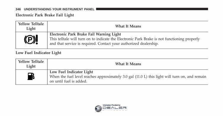
Electronic Park Brake Fail Light
Yellow TelltaleLight
What It Means
Electronic Park Brake Fail Warning LightThis telltale will turn on to indicate the Electronic Park Brake is not functioning properlyand that service is required. Contact your authorized dealership.
Low Fuel Indicator Light
Yellow TelltaleLight
What It Means
Low Fuel Indicator LightWhen the fuel level reaches approximately 3.0 gal (11.0 L) this light will turn on, and remainon until fuel is added.
346 UNDERSTANDING YOUR INSTRUMENT PANEL
Information Provided by:
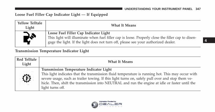
Loose Fuel Filler Cap Indicator Light — If Equipped
Yellow TelltaleLight
What It Means
Loose Fuel Filler Cap Indicator LightThis light will illuminate when fuel filler cap is loose. Properly close the filler cap to disen-gage the light. If the light does not turn off, please see your authorized dealer.
Transmission Temperature Indicator Light
Red TelltaleLight
What It Means
Transmission Temperature Indicator LightThis light indicates that the transmission fluid temperature is running hot. This may occur withsevere usage, such as trailer towing. If this light turns on, safely pull over and stop them ve-hicle. Then, shift the transmission into NEUTRAL and run the engine at idle or faster until thelight turns off.
4
UNDERSTANDING YOUR INSTRUMENT PANEL 347
Information Provided by:
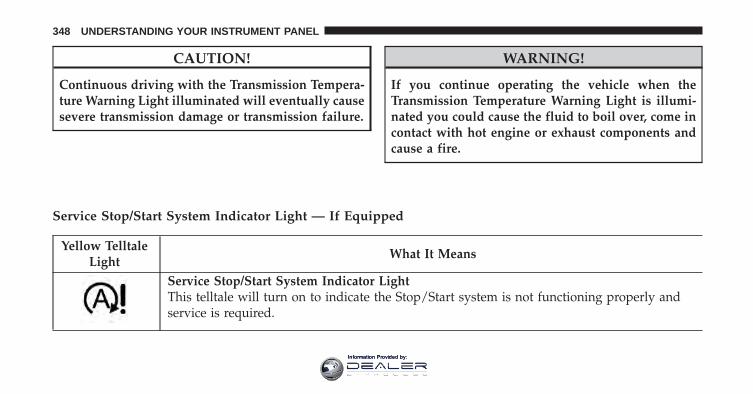
CAUTION!
Continuous driving with the Transmission Tempera-ture Warning Light illuminated will eventually causesevere transmission damage or transmission failure.
WARNING!
If you continue operating the vehicle when theTransmission Temperature Warning Light is illumi-nated you could cause the fluid to boil over, come incontact with hot engine or exhaust components andcause a fire.
Service Stop/Start System Indicator Light — If Equipped
Yellow TelltaleLight
What It Means
Service Stop/Start System Indicator LightThis telltale will turn on to indicate the Stop/Start system is not functioning properly andservice is required.
348 UNDERSTANDING YOUR INSTRUMENT PANEL
Information Provided by:
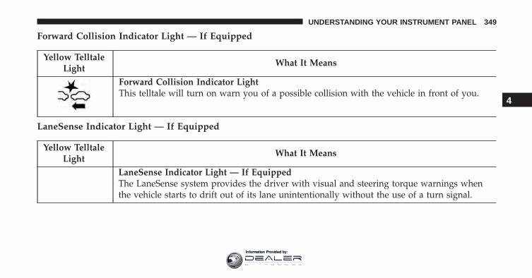
Forward Collision Indicator Light — If Equipped
Yellow TelltaleLight
What It Means
Forward Collision Indicator LightThis telltale will turn on warn you of a possible collision with the vehicle in front of you.
LaneSense Indicator Light — If Equipped
Yellow TelltaleLight
What It Means
LaneSense Indicator Light — If EquippedThe LaneSense system provides the driver with visual and steering torque warnings whenthe vehicle starts to drift out of its lane unintentionally without the use of a turn signal.
4
UNDERSTANDING YOUR INSTRUMENT PANEL 349
Information Provided by:
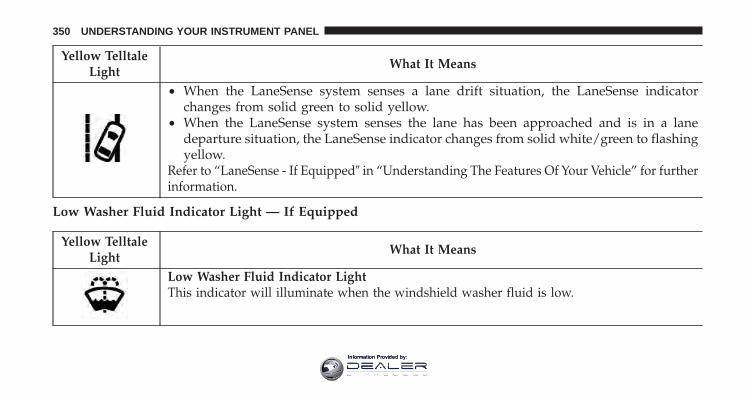
Yellow TelltaleLight
What It Means
• When the LaneSense system senses a lane drift situation, the LaneSense indicatorchanges from solid green to solid yellow.
• When the LaneSense system senses the lane has been approached and is in a lanedeparture situation, the LaneSense indicator changes from solid white/green to flashingyellow.
Refer to “LaneSense - If Equipped� in “Understanding The Features Of Your Vehicle” for furtherinformation.
Low Washer Fluid Indicator Light — If Equipped
Yellow TelltaleLight
What It Means
Low Washer Fluid Indicator LightThis indicator will illuminate when the windshield washer fluid is low.
350 UNDERSTANDING YOUR INSTRUMENT PANEL
Information Provided by:
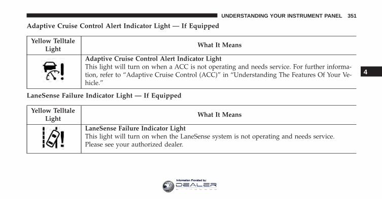
Adaptive Cruise Control Alert Indicator Light — If Equipped
Yellow TelltaleLight
What It Means
Adaptive Cruise Control Alert Indicator LightThis light will turn on when a ACC is not operating and needs service. For further informa-tion, refer to “Adaptive Cruise Control (ACC)” in “Understanding The Features Of Your Ve-hicle.”
LaneSense Failure Indicator Light — If Equipped
Yellow TelltaleLight
What It Means
LaneSense Failure Indicator LightThis light will turn on when the LaneSense system is not operating and needs service.Please see your authorized dealer.
4
UNDERSTANDING YOUR INSTRUMENT PANEL 351
Information Provided by:
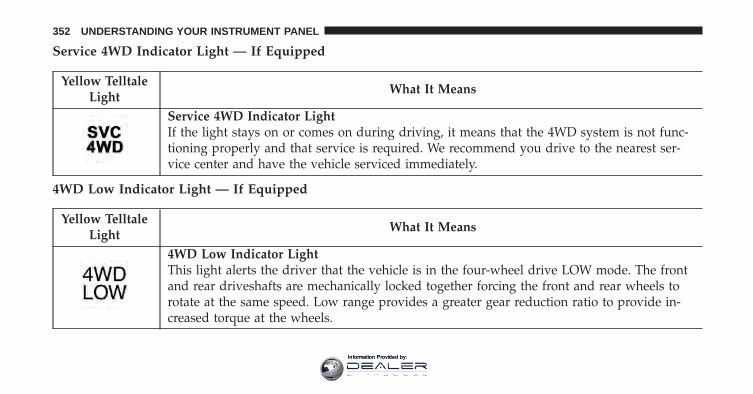
Service 4WD Indicator Light — If Equipped
Yellow TelltaleLight
What It Means
Service 4WD Indicator LightIf the light stays on or comes on during driving, it means that the 4WD system is not func-tioning properly and that service is required. We recommend you drive to the nearest ser-vice center and have the vehicle serviced immediately.
4WD Low Indicator Light — If Equipped
Yellow TelltaleLight
What It Means
4WD Low Indicator LightThis light alerts the driver that the vehicle is in the four-wheel drive LOW mode. The frontand rear driveshafts are mechanically locked together forcing the front and rear wheels torotate at the same speed. Low range provides a greater gear reduction ratio to provide in-creased torque at the wheels.
352 UNDERSTANDING YOUR INSTRUMENT PANEL
Information Provided by:
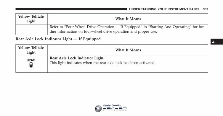
Yellow TelltaleLight
What It Means
Refer to “Four-Wheel Drive Operation — If Equipped” in “Starting And Operating” for fur-ther information on four-wheel drive operation and proper use.
Rear Axle Lock Indicator Light — If Equipped
Yellow TelltaleLight
What It Means
Rear Axle Lock Indicator LightThis light indicates when the rear axle lock has been activated.
4
UNDERSTANDING YOUR INSTRUMENT PANEL 353
Information Provided by:
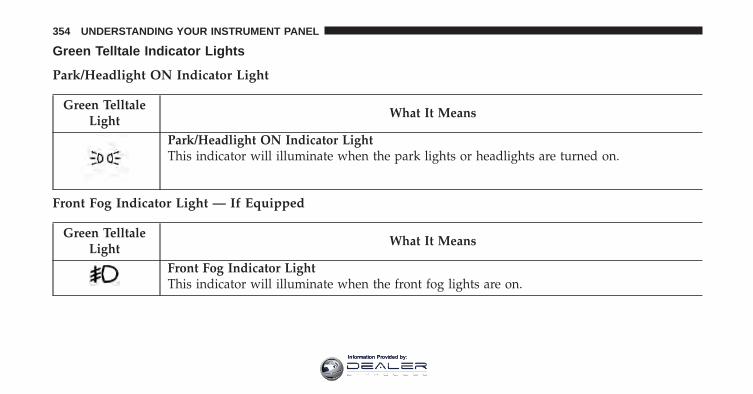
Green Telltale Indicator Lights
Park/Headlight ON Indicator Light
Green TelltaleLight
What It Means
Park/Headlight ON Indicator LightThis indicator will illuminate when the park lights or headlights are turned on.
Front Fog Indicator Light — If Equipped
Green TelltaleLight
What It Means
Front Fog Indicator LightThis indicator will illuminate when the front fog lights are on.
354 UNDERSTANDING YOUR INSTRUMENT PANEL
Information Provided by:
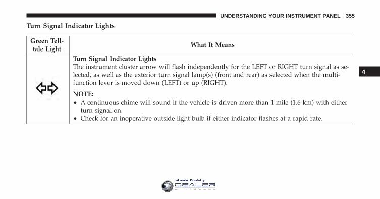
Turn Signal Indicator Lights
Green Tell-tale Light
What It Means
Turn Signal Indicator LightsThe instrument cluster arrow will flash independently for the LEFT or RIGHT turn signal as se-lected, as well as the exterior turn signal lamp(s) (front and rear) as selected when the multi-function lever is moved down (LEFT) or up (RIGHT).
NOTE:• A continuous chime will sound if the vehicle is driven more than 1 mile (1.6 km) with either
turn signal on.• Check for an inoperative outside light bulb if either indicator flashes at a rapid rate.
4
UNDERSTANDING YOUR INSTRUMENT PANEL 355
Information Provided by:
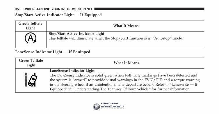
Stop/Start Active Indicator Light — If Equipped
Green TelltaleLight
What It Means
Stop/Start Active Indicator LightThis telltale will illuminate when the Stop/Start function is in “Autostop” mode.
LaneSense Indicator Light — If Equipped
Green TelltaleLight
What It Means
LaneSense Indicator LightThe LaneSense indicator is solid green when both lane markings have been detected andthe system is “armed” to provide visual warnings in the EVIC/DID and a torque warningin the steering wheel if an unintentional lane departure occurs. Refer to “LaneSense — IfEquipped� in “Understanding The Features Of Your Vehicle” for further information.
356 UNDERSTANDING YOUR INSTRUMENT PANEL
Information Provided by:
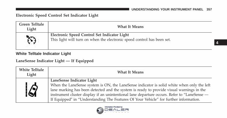
Electronic Speed Control Set Indicator Light
Green TelltaleLight
What It Means
Electronic Speed Control Set Indicator LightThis light will turn on when the electronic speed control has been set.
White Telltale Indicator Light
LaneSense Indicator Light — If Equipped
White TelltaleLight
What It Means
LaneSense Indicator LightWhen the LaneSense system is ON, the LaneSense indicator is solid white when only the leftlane marking has been detected and the system is ready to provide visual warnings in theinstrument cluster display if an unintentional lane departure occurs. Refer to “LaneSense —If Equipped� in “Understanding The Features Of Your Vehicle” for further information.
4
UNDERSTANDING YOUR INSTRUMENT PANEL 357
Information Provided by:
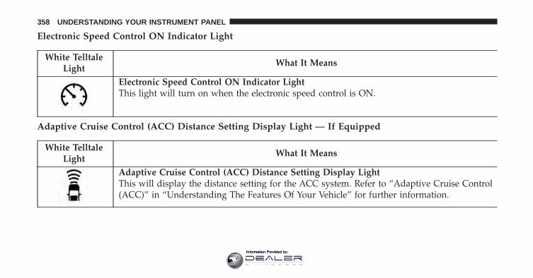
Electronic Speed Control ON Indicator Light
White TelltaleLight
What It Means
Electronic Speed Control ON Indicator LightThis light will turn on when the electronic speed control is ON.
Adaptive Cruise Control (ACC) Distance Setting Display Light — If Equipped
White TelltaleLight
What It Means
Adaptive Cruise Control (ACC) Distance Setting Display LightThis will display the distance setting for the ACC system. Refer to “Adaptive Cruise Control(ACC)” in “Understanding The Features Of Your Vehicle” for further information.
358 UNDERSTANDING YOUR INSTRUMENT PANEL
Information Provided by:
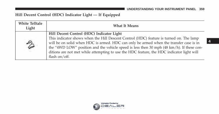
Hill Decent Control (HDC) Indicator Light — If Equipped
White TelltaleLight
What It Means
Hill Decent Control (HDC) Indicator LightThis indicator shows when the Hill Descent Control (HDC) feature is turned on. The lampwill be on solid when HDC is armed. HDC can only be armed when the transfer case is inthe “4WD LOW” position and the vehicle speed is less then 30 mph (48 km/h). If these con-ditions are not met while attempting to use the HDC feature, the HDC indicator light willflash on/off.
4
UNDERSTANDING YOUR INSTRUMENT PANEL 359
Information Provided by:
Blue Telltale Indicator Light
High Beam Indicator Light
Blue TelltaleLight
What It Means
High Beam Indicator LightThis indicator shows that the high beam headlights are on. Push the multifunction controllever away from you to switch the headlights to high beam. Pull the lever toward you toswitch the headlights back to low beam.
360 UNDERSTANDING YOUR INSTRUMENT PANEL
Information Provided by:
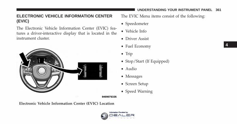
ELECTRONIC VEHICLE INFORMATION CENTER(EVIC)
The Electronic Vehicle Information Center (EVIC) fea-tures a driver-interactive display that is located in theinstrument cluster.
The EVIC Menu items consist of the following:
• Speedometer
• Vehicle Info
• Driver Assist
• Fuel Economy
• Trip
• Stop/Start (If Equipped)
• Audio
• Messages
• Screen Setup
• Speed Warning
Electronic Vehicle Information Center (EVIC) Location
4
UNDERSTANDING YOUR INSTRUMENT PANEL 361
Information Provided by:
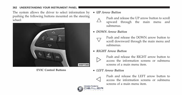
The system allows the driver to select information bypushing the following buttons mounted on the steeringwheel:
• UP Arrow Button
Push and release the UP arrow button to scrollupward through the main menu andsubmenus.
• DOWN Arrow Button
Push and release the DOWN arrow button toscroll downward through the main menu andsubmenus.
• RIGHT Arrow Button
Push and release the RIGHT arrow button toaccess the information screens or submenuscreens of a main menu item.
• LEFT Arrow Button
Push and release the LEFT arrow button toaccess the information screens or submenuscreens of a main menu item.
EVIC Control Buttons
362 UNDERSTANDING YOUR INSTRUMENT PANEL
Information Provided by:
• OK Button
Push the OK button to access/select the informationscreens or submenu screens of a main menu item. Pushand hold the OK arrow button for one second to resetdisplayed/selected features that can be reset.
Oil Change Reset
Oil Change Due
Your vehicle is equipped with an engine oil changeindicator system. The “Oil Change Due” message willdisplay in the EVIC for five seconds after a single chimehas sounded to indicate the next scheduled oil changeinterval. The engine oil change indicator system is dutycycle based, which means the engine oil change intervalmay fluctuate, dependent upon your personal drivingstyle.
Unless reset, this message will continue to display eachtime the ignition is cycled to the ON/RUN position. Toturn off the message temporarily, push and release theOK button. To reset the oil change indicator system (afterperforming the scheduled maintenance), refer to thefollowing procedure.
1. Without pushing the brake pedal, push the ENGINESTART/STOP button and cycle the ignition to theON/RUN position (do not start the engine).
2. Fully push the accelerator pedal, slowly, three timeswithin 10 seconds.
3. Without pushing the brake pedal, push the ENGINESTART/STOP button once to return the ignition to theOFF/LOCK position.
4
UNDERSTANDING YOUR INSTRUMENT PANEL 363
Information Provided by:
Secondary Method Of Navigating To The Oil LifeScreen In The DID And Holding OK
1. Without pushing the brake pedal, push the ENGINESTART/STOP button and cycle the ignition to theON/RUN position (do not start the engine).
2. Push and release the DOWN arrow button to scrolldownward through the main menu to “Vehicle Info.”
3. Push and release the RIGHT arrow button to accessthe “Oil Life” screen.
4. Push and hold the OK button to reset of the Oil Life.
5. Push and release the UP arrow button to exit thescreen.
NOTE: If the indicator message illuminates when youstart the vehicle, the oil change indicator system did notreset. If necessary, repeat this procedure.
EVIC Selectable Menu Items
Push and release the UP or DOWN arrow buttons untilthe desired Selectable Menu icon is highlighted in theEVIC.
Speedometer
Push and release the UP or DOWN arrow button untilthe Speedometer Menu item is highlighted in the EVIC.Push the OK button to change the speedometer scalefrom mph to km/h (or vice versa).
Vehicle Info (Customer Information Features)
Push and release the UP or DOWN arrow button untilthe Vehicle Info Menu item is highlighted in the EVIC.Push and release the RIGHT/LEFT arrow button to cyclethrough the Vehicle Info sub-menus, and follow theprompts on each screen as needed.
364 UNDERSTANDING YOUR INSTRUMENT PANEL
Information Provided by:
• Tire Pressure
Push and release the UP or DOWN arrow button until“Tire Pressure” is highlighted in the EVIC. Push andrelease the RIGHT arrow button and one of the followingwill be displayed:If tire pressure is OK for all tires, a vehicle ICON isdisplayed with tire pressure values in each corner of theICON.If one or more tires have low pressure, “Inflate Tire ToXX” is displayed with the vehicle ICON, and the tirepressure values in each corner of the ICON with thepressure value of the low tire displayed in a differentcolor than the other tire pressure value.If the Tire Pressure system requires service, “Service TirePressure System” is displayed.
• Tire PSI is an information only function and cannot bereset. Push and release the LEFT arrow button toreturn to the main menu.
• Refer to “Tire Pressure Monitoring System (TPMS)”under “Starting and Operating” for further informa-tion.
• Coolant Temp
Displays the actual coolant temperature.
• Transmission Temp
Displays the actual transmission temperature.
• Oil Temp
Displays the actual oil temperature.
• Oil Life
Displays the remaining oil life.
• Battery Voltage
Displays the actual battery voltage.
4
UNDERSTANDING YOUR INSTRUMENT PANEL 365
Information Provided by:
Driver Assist
Adaptive Cruise Control (ACC) Menu
The EVIC displays the current ACC system settings. Theinformation displayed depends on ACC system status.
Push the ADAPTIVE CRUISE CONTROL (ACC) ON/OFF button (located on the steering wheel) until one ofthe following displays in the EVIC:
Adaptive Cruise Control Off
When ACC is deactivated, the display will read “Adap-tive Cruise Control Off.”
Adaptive Cruise Control Ready
When ACC is activated but the vehicle speed setting hasnot been selected, the display will read “Adaptive CruiseControl Ready.”
Push and release the SET + or the SET- button (located onthe steering wheel) and the following will display in theEVIC:
ACC SET
When ACC is set, the set speed will display in theinstrument cluster.
The ACC screen may display once again if any ACCactivity occurs, which may include any of the following:
• Distance Setting Change
• System Cancel
• Driver Override
• System Off
• ACC Proximity Warning
• ACC Unavailable Warning
366 UNDERSTANDING YOUR INSTRUMENT PANEL
Information Provided by:
• The EVIC will return to the last display selected afterfive seconds of no ACC display activity.
Refer to “Adaptive Cruise Control (ACC) — IfEquipped” in “Understanding The Features Of YourVehicle” for further information.
LaneSense
The EVIC displays the current LaneSense system set-tings. The information displayed depends on LaneSensesystem status and the conditions that need to be met. Forfurther information, refer to “LaneSense — If Equipped”in “Understanding The Features Of Your Vehicle.”
Fuel Economy
Push and release the UP or DOWN arrow button untilthe Fuel Economy Menu item is highlighted. Push andhold the OK button to reset feature.
• Range
• Average Fuel Economy
• Current Fuel Economy (MPG or L/100 km)
Trip Info
Push and release the UP or DOWN arrow button untilthe Trip Menu item is highlighted in the EVIC (Toggle leftor right to select Trip A or Trip B). The Trip informationwill display the following:
• Distance
• Average Fuel Economy
• Elapsed Time
Hold the OK button to reset feature information.
4
UNDERSTANDING YOUR INSTRUMENT PANEL 367
Information Provided by:
Stop/Start Menu Item – If Equipped
Push and release the UP or DOWN arrow button untilthe Stop/Start menu item is highlighted in the EVIC.Push and release the RIGHT arrow button to display theStop/Start status.
Audio
Push and release the UP or DOWN arrow button untilthe Audio Menu item is highlighted in the EVIC.
Stored Messages
Push and release the UP or DOWN arrowbutton until the Messages Menu item is high-lighted in the EVIC. This feature shows thenumber of stored warning messages. Pushing
the RIGHT arrow button will allow you to see what thestored messages are.
Screen Setup
Push and release the UP or DOWN arrow button untilthe Screen Setup Menu item is highlighted in the EVIC.Push and release the OK button to enter the sub-menusand follow the prompts on the screen as needed. TheScreen Setup feature allows you to change what informa-tion is displayed in the instrument cluster as well as thelocation that information is displayed.
Screen Setup Driver Selectable Items
Upper Left
• Compass
• Outside Temp (default setting)
• Time
• Range To Empty (RTE)
• Average MPG or L/100 km
368 UNDERSTANDING YOUR INSTRUMENT PANEL
Information Provided by:
• Current MPG or L/100 km
• None
Upper Right
• Compass (default setting)
• Outside Temp
• Time
• Range To Empty (RTE)
• Average MPG or L/100 km
• Current MPG or L/100 km
• None
Center
• Menu Title (Default Setting)
• Compass
• Outside Temp
• Time
• Range To Empty
• Average MPG or L/100 km
• Current MPG or L/100 km
• Trip A Distance
• Trip B Distance
• Audio Information
• Digital Speed
• None
Restore To Defaults (Restores All Settings To DefaultSettings, Outside Temp UL, Compass UR, Center MenuTitle)
• OK
• Cancel
4
UNDERSTANDING YOUR INSTRUMENT PANEL 369
Information Provided by:
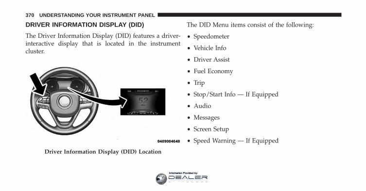
DRIVER INFORMATION DISPLAY (DID)
The Driver Information Display (DID) features a driver-interactive display that is located in the instrumentcluster.
The DID Menu items consist of the following:
• Speedometer
• Vehicle Info
• Driver Assist
• Fuel Economy
• Trip
• Stop/Start Info — If Equipped
• Audio
• Messages
• Screen Setup
• Speed Warning — If Equipped
Driver Information Display (DID) Location
370 UNDERSTANDING YOUR INSTRUMENT PANEL
Information Provided by:
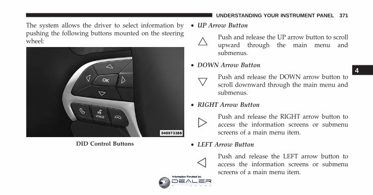
The system allows the driver to select information bypushing the following buttons mounted on the steeringwheel:
• UP Arrow Button
Push and release the UP arrow button to scrollupward through the main menu andsubmenus.
• DOWN Arrow Button
Push and release the DOWN arrow button toscroll downward through the main menu andsubmenus.
• RIGHT Arrow Button
Push and release the RIGHT arrow button toaccess the information screens or submenuscreens of a main menu item.
• LEFT Arrow Button
Push and release the LEFT arrow button toaccess the information screens or submenuscreens of a main menu item.
DID Control Buttons
4
UNDERSTANDING YOUR INSTRUMENT PANEL 371
Information Provided by:
• OK Button
Push the OK button to access/select the informationscreens or submenu screens of a main menu item. Pushand hold the OK arrow button for one second to resetdisplayed/selected features that can be reset.
Oil Change Reset
Oil Change Due
Your vehicle is equipped with an engine oil changeindicator system. The “Oil Change Due” message willdisplay in the DID for five seconds after a single chimehas sounded to indicate the next scheduled oil changeinterval. The engine oil change indicator system is dutycycle based, which means the engine oil change intervalmay fluctuate, dependent upon your personal drivingstyle.
Unless reset, this message will continue to display eachtime you turn the ignition is cycled to the ON/RUN
position. To turn off the message temporarily, push andrelease the OK button. To reset the oil change indicatorsystem (after performing the scheduled maintenance),refer to the following procedure.
Vehicles Equipped With Keyless Enter-N-Go
1. Without pushing the brake pedal, push the ENGINESTART/STOP button and cycle the ignition to theON/RUN position (do not start the engine).
2. Fully depress the accelerator pedal, slowly, three timeswithin 10 seconds.
3. Without pushing the brake pedal, push the ENGINESTART/STOP button once to return the ignition to theOFF/LOCK position.
Vehicles Not Equipped With Keyless Enter-N-Go
1. Turn the ignition switch to the ON/RUN position (donot start the engine).
372 UNDERSTANDING YOUR INSTRUMENT PANEL
Information Provided by:
2. Fully depress the accelerator pedal, slowly, three timeswithin 10 seconds.
3. Turn the ignition switch to the OFF/LOCK position.
NOTE: If the indicator message illuminates when youstart the vehicle, the oil change indicator system did notreset. If necessary, repeat this procedure.
DID Selectable Menu Items
Push and release the UP or DOWN arrow buttons untilthe desired Selectable Menu item is displayed in the DID.
Follow the Menu or submenu prompts as desired.
Speedometer
Push and release the UP or DOWN arrow button untilthe Speedometer Menu item is highlighted in the DID.Push and release the OK button to change the speedom-eter scale from mph to km/h (or vice versa).
Vehicle Info (Customer Information Features)
Push and release the UP or DOWN arrow button untilthe Vehicle Info Menu item is highlighted in the DID.Push and release the RIGHT/LEFT arrow button to cyclethrough the Vehicle Info sub-menus and follow theprompts on each screen as needed.
1. Tire Pressure
Push and release the UP or DOWN arrow button until“Tire Pressure” is highlighted in the DID. Push andrelease the RIGHT arrow button and one of the followingwill be displayed:
• If tire pressure is OK for all tires a vehicle ICON isdisplayed with tire pressure values in each corner ofthe ICON.
• If one or more tires have low pressure, “Inflate TireTo XX” is displayed with the vehicle ICON and thetire pressure values in each corner of the ICON with
4
UNDERSTANDING YOUR INSTRUMENT PANEL 373
Information Provided by:
the pressure value of the low tire displayed in adifferent color than the other tire pressure value.
• If the Tire Pressure system requires service, “ServiceTire Pressure System” is displayed.
• Tire PSI is an information only function and cannotbe reset. Push and release the LEFT arrow button toreturn to the main menu.
• Refer to “Tire Pressure Monitoring System (TPMS)”under “Starting and Operating” for further informa-tion.
2. Coolant Temperature
Displays the actual coolant temperature.
3. Transmission Temp — Automatic Transmission Only
Displays the actual transmission temperature.
4. Oil Temp
Displays the actual oil temperature.
5. Oil Life
Displays the remaining oil life.
6. Battery Voltage
Displays the actual battery voltage
Driver Assist
Adaptive Cruise Control (ACC) Menu — If Equipped
The DID displays the current ACC system settings. Theinformation displayed depends on ACC system status.
Push the ADAPTIVE CRUISE CONTROL (ACC) ON/OFF button (located on the steering wheel) until one ofthe following displays in the DID:
Adaptive Cruise Control Off
When ACC is deactivated, the display will read “Adap-tive Cruise Control Off.”
374 UNDERSTANDING YOUR INSTRUMENT PANEL
Information Provided by:
Adaptive Cruise Control Ready
When ACC is activated but the vehicle speed setting hasnot been selected, the display will read “Adaptive CruiseControl Ready.”
Push and release the SET + or the SET- button (located onthe steering wheel) and the following will display in theDID:
ACC SET
When ACC is set, the set speed will display in theinstrument cluster.
The ACC screen may display once again if any ACCactivity occurs, which may include any of the following:
• Distance Setting Change
• System Cancel
• Driver Override
• System Off
• ACC Proximity Warning
• ACC Unavailable Warning
• The DID will return to the last display selected afterfive seconds of no ACC display activity.
For further information, refer to “Adaptive Cruise Con-trol (ACC) — If Equipped” in “Understanding TheFeatures Of Your Vehicle.”
LaneSense — If Equipped
The DID displays the current LaneSense system settings.The information displayed depends on LaneSense sys-tem status and the conditions that need to be met. Forfurther information, refer to “LaneSense — If Equipped”in “Understanding The Features Of Your Vehicle.”
4
UNDERSTANDING YOUR INSTRUMENT PANEL 375
Information Provided by:
Fuel Economy
Push and release the UP or DOWN arrow button untilthe Fuel Economy Menu item is highlighted in the DID.Push and Hold the OK button to reset feature.
• Range – The display shows the estimated distance (mior km that can be traveled with the fuel remaining inthe tank. When the Range value is less than 30 miles(48 km) estimated driving distance, the Range displaywill change to a “LOW FUEL” message. Adding asignificant amount of fuel to the vehicle will turn offthe “LOW FUEL” message and a new Range value willdisplay. Range cannot be reset through the OK button.
NOTE: Significant changes in driving style or vehicleloading will greatly affect the actual drivable distance ofthe vehicle, regardless of the Range displayed value.
• Average – The display shows the average fueleconomy (MPG or L/100 km) since the last reset.
• Current – This display shows the current fuel economy(MPG or L/100 km) form while driving.
Trip Info
Push and release the UP or DOWN arrow button untilthe Trip Menu item is highlighted in the DID (Toggle leftor right to select Trip A or Trip B). The Trip informationwill display the following:
• Distance – Shows the total distance (mi or km) traveledfor Trip A or Trip B since the last reset.
• Average Fuel Economy – Shows the average fueleconomy (MPG or L/100 km) of Trip A or Trip B sincethe last reset.
• Elapsed Time – Shows the total elapsed time of travelsince the last reset.
Hold the OK button to reset feature information.
376 UNDERSTANDING YOUR INSTRUMENT PANEL
Information Provided by:
Stop/Start – If Equipped
Push and release the UP or DOWN arrow button untilthe Stop/Start icon is highlighted in the DID. Push andrelease the RIGHT arrow button to display the Stop/Start status.
Audio
Push and release the UP or DOWN arrow button untilthe Audio Menu displays in the DID.
Stored Messages
Push and release the UP or DOWN arrow button untilthe Messages Menu item is highlighted in the DID. Thisfeature shows the number of stored warning messages.Pushing the RIGHT or LEFT arrow button will allowyou to scroll through the stored messages.
Screen Setup
Push and release the UP or DOWN arrow button untilthe Screen Setup Menu displays in the DID. Push andrelease the OK button to enter the submenus. The ScreenSetup feature allows you to change what information isdisplayed in the instrument cluster as well as the locationthat information is displayed.
1. Upper Left• Compass• Outside Temp. (default)• Time• Range to Empty• Average L/100km (or MPG)• Current L/100km (or MPG)• Trip A Distance• Trip B Distance• None
4
UNDERSTANDING YOUR INSTRUMENT PANEL 377
Information Provided by:
2. Upper Right• Compass (default)• Outside Temp• Time• Range to Empty• Average L/100km (or MPG)• Current L/100km (or MPG)• Trip A Distance• Trip B Distance• None
3. Center• Menu Title (default)• Compass• Outside Temp.• Time• Range to Empty
• Average L/100km (or MPG)• Current L/100km (or MPG)• Trip A Distance• Trip B Distance• Audio Inform• None
4. Gear Display — If Equipped• Single• Full PRND (default)
5. Defaults• Ok• Cancel
378 UNDERSTANDING YOUR INSTRUMENT PANEL
Information Provided by:
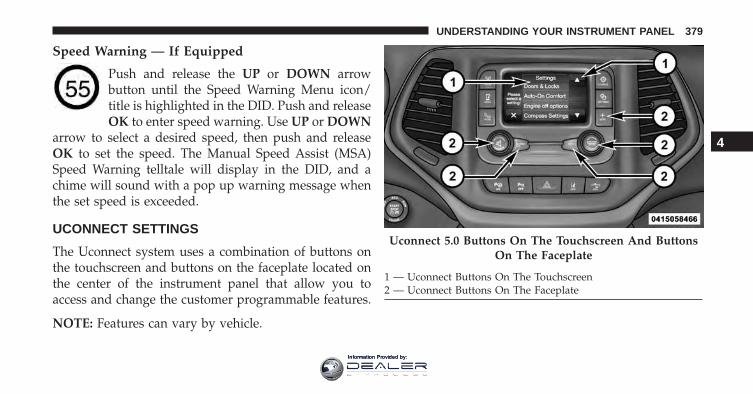
Speed Warning — If Equipped
Push and release the UP or DOWN arrowbutton until the Speed Warning Menu icon/title is highlighted in the DID. Push and releaseOK to enter speed warning. Use UP or DOWN
arrow to select a desired speed, then push and releaseOK to set the speed. The Manual Speed Assist (MSA)Speed Warning telltale will display in the DID, and achime will sound with a pop up warning message whenthe set speed is exceeded.
UCONNECT SETTINGS
The Uconnect system uses a combination of buttons onthe touchscreen and buttons on the faceplate located onthe center of the instrument panel that allow you toaccess and change the customer programmable features.
NOTE: Features can vary by vehicle.
Uconnect 5.0 Buttons On The Touchscreen And ButtonsOn The Faceplate
1 — Uconnect Buttons On The Touchscreen2 — Uconnect Buttons On The Faceplate
4
UNDERSTANDING YOUR INSTRUMENT PANEL 379
Information Provided by:
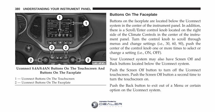
Buttons On The Faceplate
Buttons on the faceplate are located below the Uconnectsystem in the center of the instrument panel. In addition,there is a Scroll/Enter control knob located on the rightside of the Climate Controls in the center of the instru-ment panel. Turn the control knob to scroll throughmenus and change settings (i.e., 30, 60, 90), push thecenter of the control knob one or more times to select orchange a setting (i.e., ON, OFF).
Your Uconnect system may also have Screen Off andBack buttons located below the Uconnect system.
Push the Screen Off button to turn off the Uconnecttouchscreen. Push the Screen Off button a second time toturn the touchscreen on.
Push the Back button to exit out of a Menu or certainoption on the Uconnect system.
Uconnect 8.4A/8.4AN Buttons On The Touchscreen AndButtons On The Faceplate
1 — Uconnect Buttons On The Touchscreen2 — Uconnect Buttons On The Faceplate
380 UNDERSTANDING YOUR INSTRUMENT PANEL
Information Provided by:
Buttons On The Touchscreen
Buttons on the touchscreen are accessible on theUconnect display.
Customer Programmable Features/PersonalSettings — Uconnect 5.0 Settings
Push the SETTINGS or the MORE button on the face-plate, then the “Settings” button on the touchscreen (ifequipped) to display the menu setting screen. In thismode the Uconnect system allows you to access pro-grammable features that may be equipped such as Dis-play, Voice, Clock & Date, Safety & Assistance, Lights,Doors & Locks, Auto-On Comfort, Engine Off Options,Compass Settings, Audio, Phone/Bluetooth, Sirius Setup,Restore Settings, and Clear Personal Data, Brakes andSystem Information.
NOTE: Only one category may be selected at a time.
When making a selection, press the button on the touch-screen to enter the desired mode. Once in the desiredmode, press and release the preferred setting and makeyour selection. Once the setting is complete, either pressthe Back Arrow/Done button on the touchscreen or theBack button on the faceplate to return to the previousmenu or press the “X” button on the touchscreen to closeout of the settings screen. Pressing the Up or DownArrow buttons on the right side of the screen will allowyou to toggle up or down through the available settings.
Display
After pressing the “Display” button on the touchscreenthe following settings will be available.
• Display Mode
When in this display you may select the “Auto” or“Manual” display settings. To change Mode status, press
4
UNDERSTANDING YOUR INSTRUMENT PANEL 381
Information Provided by:
and release the “Auto” or “Manual” button on thetouchscreen. Then press the arrow back button on thetouchscreen.
NOTE: When Day or Night is selected for the DisplayMode, the usage of the Parade Mode feature will causethe radio to activate the Display Brightness Day controleven though the headlights are on.
• Display Brightness With Headlights ON
When in this display, you may select the overall screenbrightness with the headlights on. Adjust the brightnesswith the “+” and “–” setting buttons on the touchscreenor by selecting any point on the scale between the “+”and “–” buttons on the touchscreen.
NOTE: To make changes to the �Display Brightness withHeadlights ON� setting, the headlights must be on andthe interior dimmer switch must not be in the �party� or�parade� positions.
• Display Brightness With Headlights OFF
When in this display, you may select the overall screenbrightness with the headlights off. Adjust the brightnesswith the “+” and “–” setting buttons on the touchscreenor by selecting any point on the scale between the “+”and “–” buttons on the touchscreen.
NOTE: To make changes to the �Display Brightness withHeadlights OFF� setting, the headlights must be off andthe interior dimmer switch must not be in the �party� or�parade� positions.
• Set Language
When in this display, you may select one of multiplelanguages (English / Français / Español) for all displaynomenclature, including the trip functions and the navi-gation system (if equipped). Press the “Set Language”button on the touchscreen, then select the desired lan-guage button on the touchscreen.
382 UNDERSTANDING YOUR INSTRUMENT PANEL
Information Provided by:
• Units
When in this display, you may select to have the DID,odometer, and navigation system (if equipped) changedbetween US and Metric units of measure. Press “US” or“Metric” to make your selection.
• Touchscreen Beep
When in this display, you may turn on or shut off thesound heard when a button on the touchscreen ispressed. Press the “Touchscreen Beep” button on thetouchscreen then select from “on” or “off.”
• Navigation Turn-By-Turn In Cluster — If Equipped
When this feature is selected, the turn-by-turn directionswill appear in the display as the vehicle approaches adesignated turn within a programmed route. To make yourselection, press the “Navigation Turn-By-Turn In Cluster”button on the touchscreen, until a check-mark appears nextto the setting, showing that setting has been selected.
• Control Screen Time-Out — If Equipped
When this feature is selected, the Controls Screen willstay open for five seconds before the screen times out.With the feature deselected, the screen will stay openuntil it is manually closed. Press the Control ScreenTime-Out button on the touchscreen until a check-markappears next to the setting, showing that setting has beenselected.
Voice
After pressing the “Voice” button on the touchscreen thefollowing settings will be available:
• Voice Response Length
When in this display, you may change the Voice Re-sponse Length settings. To change the Voice ResponseLength, press the “Voice Response Length” button on thetouchscreen and select from “Brief” or “Detailed.”
4
UNDERSTANDING YOUR INSTRUMENT PANEL 383
Information Provided by:
• Show Command List
When in this display, you may change the Show Com-mand List settings. To change the Show Command Listsettings, press the “Show Command List” button on thetouchscreen and select from “Always,” “With Help” or“Never.”
Clock & Date
After pressing the “Clock & Date” button on the touch-screen the following settings will be available:
• Set Time
When in this display, you may set the time and formatmanually. Press the “Set Time” button then choose froma “12 hour” or “24 hour format.” Press the correspondingarrow above and below the current time to adjust, thenselect “AM” or “PM.”
• Set Date
When in this display, you may set the date manually.Press the “Set Date” button then press the correspondingarrows above and below the current date to adjust.
Safety & Driving Assistance
After pressing the “Safety & Driving Assistance” buttonon the touchscreen the following settings will be avail-able:
• Forward Collision Warning (FCW) — If Equipped
The Front Collision Warning (FCW) feature can be can beset to Far, or set to Near. The default status of FCW is theFar setting. This means the system will warn you of apossible collision with the vehicle in front of you whenyou are farther away. This gives you the most reactiontime. To change the setting for a more dynamic drivingexperience, select the Near setting. This warns you of a
384 UNDERSTANDING YOUR INSTRUMENT PANEL
Information Provided by:
possible collision when you are much closer to thevehicle in front of you. To change the FCW status, pressand release the “Near” or “Far” button.
For further information, refer to “Adaptive Cruise Con-trol (ACC)” in “Understanding The Features Of YourVehicle”.
• Forward Collision Warning (FCW) Active Braking —If Equipped
The FCW system includes Advanced Brake Assist (ABA).When this feature is selected, it will apply the brakes toslow your vehicle in case of potential forward collision.The ABA applies additional brake pressure when thedriver requests insufficient brake pressure to avoid apotential frontal collision. The ABA system becomesactive at 5 mph (8 km/h).
For further information, refer to “Forward CollisionWarning (FCW) With Mitigation” in “Understanding TheFeatures Of Your Vehicle”.
• LaneSense Warning — If Equipped
When this feature is selected, it sets the distance at whichthe steering wheel will provide feedback for potentiallane departures. The LDW sensitivity can be set toprovide either an “early,” “medium,” or “late” warningzone start point.
For further information, refer to “LaneSense Warning(LDW)” in “Understanding The Features Of Your Vehicle”.
• LaneSense Strength — If Equipped
When this feature is selected, it sets the strength of thesteering wheel feedback for potential lane departures.The amount of directional torque the steering system canapply to the steering wheel to correct for vehicle lanedeparture can be set at “Low,” “Medium” or “High.”
4
UNDERSTANDING YOUR INSTRUMENT PANEL 385
Information Provided by:
For further information, refer to “Lane Departure Warn-ing (LDW)” in “Understanding The Features Of YourVehicle”.
• ParkSense — If Equipped
The Rear Park Assist system will scan for objects behindthe vehicle when the transmission shift lever is in RE-VERSE and the vehicle speed is less than 11 mph(18 km/h). The system can be enabled with Sound Only,or Sound and Display. To change the Park Assist status,press and release the “Sound” or “Sound and Display”button.
Refer to “ParkSense Rear Park Assist” in “UnderstandingThe Features Of Your Vehicle” for system function andoperating information.
• Front ParkSense Volume — If Equipped
Front Park Assist chime volume settings can be selectedfrom the EVIC/DID or Uconnect System (if equipped).
The chime volume settings include “LOW,” “MEDIUM,”and “HIGH.” The factory default volume setting isMEDIUM.
• Rear ParkSense Volume — If Equipped
Rear Park Assist chime volume settings can be selectedfrom the EVIC/DID or Uconnect System (if equipped).The chime volume settings include “LOW,” “MEDIUM,”and “HIGH.” The factory default volume setting isMEDIUM.
• Rear ParkSense Braking Assist — If Equipped
When this feature is selected, the park assist system willdetect objects located behind the vehicle and utilizeautonomous braking to stop the vehicle.
Refer to “ParkSense Rear Park Assist” in “UnderstandingThe Features Of Your Vehicle” for system function andoperating information.
386 UNDERSTANDING YOUR INSTRUMENT PANEL
Information Provided by:
• Tilt Mirrors In Reverse — If Equipped
When this feature is selected, the exterior sideviewmirrors will tilt downward when the ignition is in theRUN position and the transmission shift lever is in theREVERSE position. The mirrors will move back to theirprevious position when the transmission is shifted out ofREVERSE. To make your selection, press the “Tilt MirrorsIn Reverse” button on the touchscreen, and select “On”or “Off.”
• Blind Spot Alert — If Equipped
When this feature is selected, the Blind Spot Alert featurecan be set to Off, Lights or Lights and Chime. The BlindSpot Alert feature can be activated in Lights mode. Whenthis mode is selected, the Blind Spot Monitor (BSM)system is activated and will only show a visual alert inthe outside mirrors. When Lights & Chime mode isactivated, the Blind Spot Monitor (BSM) will show avisual alert in the outside mirrors as well as an audible
alert when the turn signal is on. When Off is selected, theBlind Spot Monitor (BSM) system is deactivated. Tochange the Blind Spot Alert status, press the “Off,”“Lights” or “Lights & Chime” button on the touchscreen.
NOTE: If your vehicle has experienced any damage inthe area where the sensor is located, even if the fascia isnot damaged, the sensor may have become misaligned.Take your vehicle to an authorized dealer to verify sensoralignment. A sensor that is misaligned will result in theBSM not operating to specification.
• ParkView Backup Camera Active Guide Lines — IfEquipped
When this feature is enabled, active (dynamic) grid linesare overlaid on the Rear Backup Camera image toillustrate the width of the vehicle and its projected backup path based on the steering wheel position. A dashedcenter line overlay indicates the center of the vehicle toassist with parking or aligning to a hitch/receiver.
4
UNDERSTANDING YOUR INSTRUMENT PANEL 387
Information Provided by:
• ParkView Backup Camera Fixed Guide Lines — IfEquipped
When this feature is enabled, fixed (static) grid lines areoverlaid on the Rear Backup Camera image to illustratethe width of the vehicle.
• ParkView Backup Camera Delay
When this feature is enabled, it will allow the ParkViewBackup Camera display to remain on while in drive forup to 10 seconds, or 8 mph (13 km/h).
• Rain Sensing Auto Wipers
When this feature is selected, the system will automati-cally activate the windshield wipers if it senses moistureon the windshield. To make your selection, press the“Rain Sensing” button on the touchscreen, and select“On” or “Off.”
• Electric Park Brake Service Mode
This feature provides a means for a technician or vehicleowner to utilize a vehicle integrated, menu driven sys-tem, to command the electric park brake retraction, toservice the rear foundation brakes (brake pads, calipers,rotors, etc.).
For further information, refer to “Electric Parking Brake(EPD)” in “Starting and Operating.”
Lights
After pressing the “Lights” button on the touchscreen thefollowing settings will be available.
• Headlights Off Delay
When this feature is selected, it allows the adjustment ofthe amount of time the headlights remain on after theengine is shut off. To change the Headlights Off Delay
388 UNDERSTANDING YOUR INSTRUMENT PANEL
Information Provided by:
setting, press the “Headlight Off Delay” button on thetouchscreen, and choose either 0 sec, 30 sec, 60 sec or 90seconds.
• Headlight Illumination On Approach
When this feature is selected, it allows the adjustment ofthe amount of time the headlights remain on after thedoors are unlocked with the Remote Keyless Entry (RKE)transmitter. To change the Illuminated Approach status,press the “Illuminated Approach” button and chooseeither 0 sec, 30 sec, 60 sec or 90 seconds.
• Headlights With Wipers — If Equipped
When this feature is selected, and the headlight switch isin the AUTO position, the headlights will turn on ap-proximately 10 seconds after the wipers are turned on.The headlights will also turn off when the wipers areturned off if they were turned on by this feature. To makeyour selection, press the “Lights w/Wipers” button onthe touchscreen and make your selection.
• Auto High Beams — If Equipped
When this feature is selected, the high beam headlightswill activate/deactivate automatically under certain con-ditions. To make your selection, press the “Auto HighBeams” button on the touchscreen and make your selec-tion. Refer to “Automatic High Beam Headlamp Control— If Equipped” in “Understanding The Features Of YourVehicle” for further information.
• Daytime Running Lights — If Equipped
When this feature is selected, the headlights will turn onwhenever the engine is running. To make your selection,press the “Daytime Running Lights” button on the touch-screen and make your selection.
4
UNDERSTANDING YOUR INSTRUMENT PANEL 389
Information Provided by:
• Flash Lights w/Lock
When this feature is selected, the exterior lights will flashwhen the doors are locked or unlocked with the RemoteKeyless Entry (RKE) transmitter or the Passive EntryFeature. To make your selection, press the “Flash Lightsw/Lock” button on the touchscreen and select from “On”or “Off.”
Doors & Locks
After pressing the “Doors & Locks” button on the touch-screen the following settings will be available.
• Auto Door Locks
When this feature is selected, all doors will lock auto-matically when the vehicle reaches a speed of 15 mph(24 km/h). To make your selection, press the “Auto DoorLocks” button on the touchscreen and select from “On”or “Off.”
• Auto Unlock On Exit
When this feature is selected, all doors will unlock whenthe vehicle is stopped and the transmission is in thePARK or NEUTRAL position and the driver’s door isopened. To make your selection, press the “Auto UnlockOn Exit” button on the touchscreen and select from “On”or “Off.”
• Flash Lights w/Lock
When this feature is selected, the exterior lights will flashwhen the doors are locked or unlocked with the RemoteKeyless Entry (RKE) transmitter or the Passive EntryFeature. To make your selection, press the “Flash Lightsw/Lock” button on the touchscreen and select from “On”or “Off.”
390 UNDERSTANDING YOUR INSTRUMENT PANEL
Information Provided by:
• Horn w/Lock
When this feature is selected, the horn will sound whenthe Key Fob Lock button is pressed. To make yourselection, press the “Sound Horn With Lock” button onthe touchscreen and select from “Off,” ”1st Press,” or“2nd Press.”
• Horn w/Remote Start — If Equipped
When this feature is selected, the horn will sound whenthe remote start is activated. To make your selection,press the “Horn w/Remote Start” button on the touch-screen and select from “On” or “Off.”
• Remote Door Unlock
When “Remote Door Unlock” is selected, you maychoose from “Driver” or “All.” Select “All” to have alldoors unlock with the first push of the Key Fob. Select“Driver” to have the only the driver door open with thefirst push of the key fob.
NOTE: Passive Entry — If Equipped. If “All” is selected,all doors will unlock no matter which Passive Entry doorhandle is grasped. If “Driver” is selected, only the driver’sdoor will unlock when the driver’s door is grasped.
• Passive Entry
This feature allows you to lock and unlock the vehicle’sdoor(s) without having to press the Remote KeylessEntry (RKE) transmitter lock or unlock buttons. To makeyour selection, press the “Passive Entry” button on thetouchscreen and select from “On” or “Off. Refer to“Keyless Enter-N-Go” in “Things To Know Before Start-ing Your Vehicle” for further information.
4
UNDERSTANDING YOUR INSTRUMENT PANEL 391
Information Provided by:
• Memory Linked to Fob — If Equipped
This feature provides automatic driver seat positioning toenhance driver mobility when entering and exiting thevehicle. To make your selection, press the “MemoryLinked to Fob” button on the touchscreen and select from“On” or “Off.”
NOTE: The seat will return to the memorized seatlocation if “Memory Linked to Fob” is set to (ON) whenthe Remote Keyless Entry (RKE) transmitter is used tounlock the door. Refer to “Driver Memory Seat” in“Understanding The Features Of Your Vehicle” for fur-ther information.
• Power Lift Gate Alert — If Equipped
This feature plays an alert when the power lift gate israising or lowering. To make your selection, press the“Power Lift Gate Alert” button on the touchscreen andselect from “On” or “Off.”
Auto Comfort Systems — If Equipped
After pressing the “Auto-On Comfort & Remote Start”button on the touchscreen the following settings will beavailable:
• Auto-On Driver Heated/Ventilated Seat & SteeringWheel With Vehicle Start — If Equipped
When this feature is selected the driver’s heated seat andheated steering wheel will automatically turn ON whentemperatures are below 40° F (4.4° C). When tempera-tures are above 80° F (26.7° C) the driver vented seat willturn ON. To make your selection, press the “Auto HeatedSeats” button on the touchscreen, then select either “Off,”“Remote Start” or “All Starts.”
Engine Off Options
After pressing the “Engine Off Options” button on thetouchscreen the following settings will be available.
392 UNDERSTANDING YOUR INSTRUMENT PANEL
Information Provided by:
• Easy Exit Seats — If Equipped
When this feature is selected, the Driver’s seat willautomatically move rearward once the engine is shut off.To make your selection, press the “Easy Exit Seats”button on the touchscreen and make your selection.
• Engine Off Power Delay
When this feature is selected, the power windowswitches, radio, Uconnect phone system (if equipped),DVD video system (if equipped), power sunroof (ifequipped), and power outlets will remain active for up to10 minutes after the ignition is cycled to OFF. Openingeither front door will cancel this feature. To change theEngine Off Power Delay status press the “0 seconds,” “45seconds,” “5 minutes” or “10 minutes” button on thetouchscreen.
• Headlight Off Delay
When this feature is selected, the driver can choose tohave the headlights remain on for 0, 30, 60, or 90 secondswhen exiting the vehicle. To change the Headlight OffDelay status press the “+” or “–” button on the touch-screen to select your desired time interval.
Compass Settings — If Equipped
After pressing the “Compass Settings” button on thetouchscreen the following settings will be available:
NOTE: Before compass calibration is performed, thecompass variance zone should be set for best results.
4
UNDERSTANDING YOUR INSTRUMENT PANEL 393
Information Provided by:
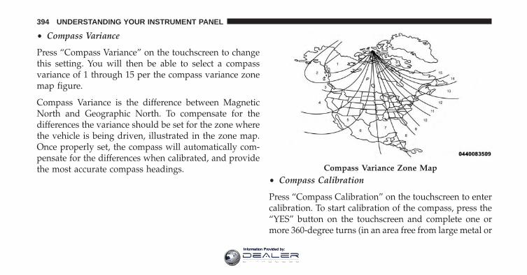
• Compass Variance
Press “Compass Variance” on the touchscreen to changethis setting. You will then be able to select a compassvariance of 1 through 15 per the compass variance zonemap figure.
Compass Variance is the difference between MagneticNorth and Geographic North. To compensate for thedifferences the variance should be set for the zone wherethe vehicle is being driven, illustrated in the zone map.Once properly set, the compass will automatically com-pensate for the differences when calibrated, and providethe most accurate compass headings.
• Compass Calibration
Press “Compass Calibration” on the touchscreen to entercalibration. To start calibration of the compass, press the“YES” button on the touchscreen and complete one ormore 360-degree turns (in an area free from large metal or
Compass Variance Zone Map
394 UNDERSTANDING YOUR INSTRUMENT PANEL
Information Provided by:
metallic objects). A message will appear on the touch-screen when the compass has been successfully cali-brated.
NOTE: Keep magnetic materials away from the top of theinstrument panel, such as Mobile Phones, Laptops andRadar Detectors. This is where the compass module islocated, and it can cause interference with the compasssensor, and it may give false readings.
Audio
After pressing the “Audio” button on the touchscreen thefollowing settings will be available:
• Equalizer
When in this display you may adjust the Bass, Mid andTreble settings. Adjust the settings with the “+” and “–”buttons on the touchscreen or by selecting any point onthe scale between the “+” and “–” buttons on thetouchscreen.
• Balance/Fade
This feature allows you to adjust the Balance and Fadesettings. Press and drag the speaker icon or use thearrows to adjust, tap the “C” icon to readjust to the center.
• Speed Adjusted Volume
This feature increases or decreases volume relative tovehicle speed. To change the Speed Adjusted Volumepress the “Speed Adjusted Volume” button on the touch-screen and select from “Off,” “1,” “2” or “3” buttons onthe touchscreen.
• Surround Sound — If Equipped
This feature provides simulated surround sound mode.To make your selection, press the “Surround Sound”button on the touchscreen, select “On” or “Off.”
4
UNDERSTANDING YOUR INSTRUMENT PANEL 395
Information Provided by:
• AUX Volume Offset — If Equipped
This feature provides the ability to tune the audio levelfor portable devices connected through the AUX input.To make your selection, press the “AUX Volume Offset”button on the touchscreen, select “On” or “Off.”
• Loudness — If Equipped
This feature improves sound quality at lower volumes.To make your selection, press the “Loudness” button onthe touchscreen, select “On” or “Off.”
Phone/Bluetooth
After pressing the “Phone/Bluetooth” button on thetouchscreen the following settings will be available:
• Paired Phones
This feature shows which phones are paired to thePhone/Bluetooth system. For further information, referto the Uconnect Supplement Manual.
• Paired Audio Sources
This feature shows which audio devices are paired to thePhone/Bluetooth system. For further information, referto the Uconnect Supplement Manual.
SiriusXM Setup — If Equipped
After pressing the “SiriusXM Setup” button on the touch-screen, the following settings will be available:
• Channel Skip
SiriusXM can be programmed to designate a group ofchannels that are the most desirable to listen to or toexclude undesirable channels while scanning. To makeyour selection, press the “Channel Skip” button on thetouchscreen, select the channels you would like to skipfollowed by pressing the back arrow button on thetouchscreen.
396 UNDERSTANDING YOUR INSTRUMENT PANEL
Information Provided by:
• Subscription Information
New vehicle purchasers or lessees will receive a freelimited time subscription to SiriusXM Satellite Radiowith your radio. Following the expiration of the freeservices, it will be necessary to access the information onthe Subscription Information screen to re-subscribe.
Press the “Subscription Info” button on the touchscreento access the Subscription Information screen.
Write down the SIRIUS ID numbers for your receiver. Toreactivate your service, either call the number listed onthe screen or visit the provider online.
NOTE: SiriusXM Travel Link is a separate subscriptionand is available for U.S. residents only.
Restore Settings
After pressing the “Restore Settings” button on thetouchscreen the following settings will be available:
• Restore Settings
When this feature is selected it will reset the Display,Clock, Audio, and Radio Settings to their default settings.To restore the settings to their default setting, press theRestore Settings button. A pop-up will appear asking�Are you sure you want to reset your settings to default?”select “Yes” to restore, or “Cancel” to exit. Once thesettings are restored, a pop up appears stating �settingsreset to default.�
4
UNDERSTANDING YOUR INSTRUMENT PANEL 397
Information Provided by:
Clear Personal Data
After pressing the “Clear Personal Data Settings” buttonon the touchscreen the following settings will be avail-able:
• Clear Personal Data
When this feature is selected it will remove personal dataincluding Bluetooth devices and presets. To removepersonal information, press the “Clear Personal Data”button and a pop-up will appear asking �Are you sureyou want to clear all personal data?” select “Yes” to Clear,or “Cancel” to exit. Once the data has been cleared, a popup appears stating �Personal data cleared”.
Customer Programmable Features/PersonalSettings — Uconnect 8.4 Personal Settings
Press the “Apps” or the “Controls” button on the touch-screen, then press the “Settings” button on the touch-screen to display the menu setting screen. In this mode
the Uconnect system allows you to access programmablefeatures that may be equipped such as Display, Voice,Clock, Safety & Driving Assistance, Lights, Doors &Locks, Auto-On Comfort, Engine Off Options, Audio,Phone/Bluetooth, SiriusXM Setup, Restore Settings,Clear Personal Data, and System Information.
NOTE: Only one category may be selected at a time.
To adjust the setting of a programmable feature, press thedesired setting option. Once in the desired setting option,press and release the preferred setting until a check-markappears next to the setting, showing that the setting hasbeen selected.
Once the setting is complete, press the Back Arrowbutton on the touchscreen to return to the previous menuor press the X button on the touchscreen to close out ofthe settings screen. Pressing the Up or Down Arrowbutton on the right side of the screen will allow you totoggle up or down through the list of available settings.
398 UNDERSTANDING YOUR INSTRUMENT PANEL
Information Provided by:
Display
After pressing the “Display” button on the touchscreenthe following settings will be available.
• Display Mode
When in this display you may select one of the autodisplay settings. To change Mode status, select from“Day,” “Night” or “Auto” until a check-mark appearsnext to the setting, showing that setting has been se-lected.
NOTE: When Day or Night is selected for the DisplayMode, the usage of the Parade Mode feature will causethe radio to activate the Display Brightness Day controleven though the headlights are on.
• Display Brightness With Headlights ON
When in this display, you may select the brightness withthe headlights on. Adjust the brightness with the “+” and
“–” setting buttons on the touchscreen or by selecting anypoint on the scale between the “+” and “–” buttons on thetouchscreen.
NOTE: To make changes to the �Display Brightness withHeadlights ON� setting, the headlights must be on andthe interior dimmer switch must not be in the �party� or�parade� positions.
• Display Brightness With Headlights OFF
When in this display, you may select the brightness withthe headlights off. Adjust the brightness with the “+” and“–” setting buttons on the touchscreen or by selecting anypoint on the scale between the “+” and “–” buttons on thetouchscreen.
NOTE: To make changes to the �Display Brightness withHeadlights OFF� setting, the headlights must be off andthe interior dimmer switch must not be in the �party� or�parade� positions.
4
UNDERSTANDING YOUR INSTRUMENT PANEL 399
Information Provided by:
• Set Theme
This feature will allow you to choose a backgroundtheme for the display screen. The theme will change thebackground color, highlight color, and button color of thedisplay screen.
• Set Language
When in this display, you may select one of multiplelanguages (English/Français/Español) for all display no-menclature, including the trip functions and the naviga-tion system (if equipped). Press the “Set Language”button on the touchscreen, then select the desired lan-guage button on the touchscreen.
• Touchscreen Beep
When in this display, you may turn on or shut off thesound heard when button on the touchscreen is pressed.
Press the “Touchscreen Beep” button on the touchscreenuntil a check-mark appears next to the setting, showingthat setting has been selected.
• Controls Screen Time-Out
When in this display, you may turn on or shut off theability for the controls screen to time out. Press the“Controls Screen Time-Out” button on the touchscreenuntil a check-mark appears next to the setting, showingthat setting has been selected.
• Navigation Turn-By-Turn Displayed In Cluster — IfEquipped
When this feature is selected, To make your selection,press the “Navigation Turn-By-Turn Displayed In Clus-ter” button on the touchscreen, until a check-mark ap-pears next to the setting, showing that setting has beenselected.
400 UNDERSTANDING YOUR INSTRUMENT PANEL
Information Provided by:
Voice
After pressing the “Voice” button on the touchscreen thefollowing settings will be available:
• Voice Response Length
When in this display, you may change the Voice Re-sponse Length settings. To change the Voice ResponseLength, press the “Brief” or “Detailed” button on thetouchscreen until a check-mark appears next to thesetting, showing that setting has been selected.
• Show Command List
When in this display, you may choose to Always, WithHelp, or Never display the Teleprompter with possibleoptions while in a voice session. To change the ShowCommand List settings, press the “Always,” “WithHelp,” or “Never” button on the touchscreen until acheck-mark appears next to the setting, showing thatsetting has been selected.
Clock
After pressing the “Clock” button on the touchscreen thefollowing settings will be available:
• Sync Time With GPS
This feature will allow the radio to sync time with a GPSsignal. To change the Sync Time setting, press the “Synctime with GPS” button on the touchscreen until a check-mark appears next to the setting, showing that setting hasbeen selected.
• Set Time Hours
This feature will allow you to adjust the hours. The “Synctime with GPS” button on the touchscreen must beunchecked. To make your selection, press the “+” or “–”buttons on the touchscreen to adjust the hours up ordown.
4
UNDERSTANDING YOUR INSTRUMENT PANEL 401
Information Provided by:
• Set Time Minutes
This feature will allow you to adjust the minutes. The“Sync time with GPS” button on the touchscreen must beunchecked. To make your selection, press the “+” or “–”buttons on the touchscreen to adjust the minutes up ordown.
• Time Format
This feature will allow you to select the time formatdisplay setting. Press the “Time Format” button on thetouchscreen until a check-mark appears next to the “12hrs” or “24 hrs” setting, showing that setting has beenselected.
• Show Time In Status Bar — If Equipped
This feature will allow you to turn on or shut off thedigital clock in the status bar. To change the Show TimeStatus setting press the “Show Time in Status Bar” button
on the touchscreen until a check-mark appears next tosetting, indicating that the setting has been selected.
Safety & Driving Assistance
After pressing the “Safety & Driving Assistance” buttonon the touchscreen the following settings will be avail-able:
• Forward Collision Warning (FCW) — If Equipped
The Front Collision Warning (FCW) feature can be can beset to Far, or set to Near. The default status of FCW is theFar setting. This means the system will warn you of apossible collision with the vehicle in front of you whenyou are farther away. This gives you the most reactiontime. To change the setting for a more dynamic drivingexperience, select the Near setting. This warns you of apossible collision when you are much closer to thevehicle in front of you. To change the FCW status, pressand release the “Near” or “Far” button.
402 UNDERSTANDING YOUR INSTRUMENT PANEL
Information Provided by:
For further information, refer to “Adaptive Cruise Con-trol (ACC)” in “Understanding The Features Of YourVehicle”.
• Forward Collision Warning (FCW) Active Braking —If Equipped
The FCW system includes Advanced Brake Assist (ABA).When this feature is selected, it will apply the brakes toslow your vehicle in case of potential forward collision.The ABA applies additional brake pressure when thedriver requests insufficient brake pressure to avoid apotential frontal collision. The ABA system becomesactive at 5 mph (8 km/h).
For further information, refer to “Forward CollisionWarning (FCW) With Mitigation” in “Understanding TheFeatures Of Your Vehicle”.
• LaneSense Warning — If Equipped
When this feature is selected, it sets the distance at whichthe steering wheel will provide feedback for potentiallane departures. The LDW sensitivity can be set toprovide either an “early,” “medium,” or “late” warningzone start point.
For further information, refer to “LaneSense Warning(LDW)” in “Understanding The Features Of Your Ve-hicle”.
• LaneSense Strength — If Equipped
When this feature is selected, it sets the strength of thesteering wheel feedback for potential lane departures.The amount of directional torque the steering system canapply to the steering wheel to correct for vehicle lanedeparture can be set at “Low,” “Medium” or “High.”
4
UNDERSTANDING YOUR INSTRUMENT PANEL 403
Information Provided by:

For further information, refer to “Lane Departure Warn-ing (LDW)” in “Understanding The Features Of YourVehicle”.
• ParkSense — If Equipped
The Rear Park Assist system will scan for objects behindthe vehicle when the transmission shift lever is in RE-VERSE and the vehicle speed is less than 11 mph(18 km/h). The system can be enabled with Sound Only,or Sound and Display. To change the Park Assist status,press and release the “Sound” or “Sound and Display”button.
Refer to “ParkSense Rear Park Assist” in “UnderstandingThe Features Of Your Vehicle” for system function andoperating information.
• Front ParkSense Volume — If Equipped
Front Park Assist chime volume settings can be selectedfrom the EVIC/DID or Uconnect System (if equipped).
The chime volume settings include “LOW,” “MEDIUM,”and “HIGH.” The factory default volume setting isMEDIUM.
• Rear ParkSense Volume — If Equipped
Rear Park Assist chime volume settings can be selectedfrom the EVIC/DID or Uconnect System (if equipped).The chime volume settings include “LOW,” “MEDIUM,”and “HIGH.” The factory default volume setting isMEDIUM.
• Rear ParkSense Braking Assist — If Equipped
When this feature is selected, the park assist system willdetect objects located behind the vehicle and utilizeautonomous braking to stop the vehicle.
Refer to “ParkSense Rear Park Assist” in “UnderstandingThe Features Of Your Vehicle” for system function andoperating information.
404 UNDERSTANDING YOUR INSTRUMENT PANEL
Information Provided by:
• Tilt Mirrors In Reverse — If Equipped
When this feature is selected, the exterior sideviewmirrors will tilt downward when the ignition is in theRUN position and the transmission shift lever is in theREVERSE position. The mirrors will move back to theirprevious position when the transmission is shifted out ofREVERSE. To make your selection, press the “Tilt MirrorsIn Reverse” button on the touchscreen, until a check-mark appears next to setting, showing that setting hasbeen selected.
• Blind Spot Alert — If Equipped
When this feature is selected, the Blind Spot Alert featurecan be set to Off, Lights or Lights and Chime. The BlindSpot Alert feature can be activated in Lights mode. Whenthis mode is selected, the Blind Spot Monitor (BSM)system is activated and will only show a visual alert inthe outside mirrors. When Lights & Chime mode isactivated, the Blind Spot Monitor (BSM) will show a
visual alert in the outside mirrors as well as an audiblealert when the turn signal is on. When Off is selected, theBlind Spot Monitor (BSM) system is deactivated. Tochange the Blind Spot Alert status, press the “Off,”“Lights” or “Lights & Chime” button on the touchscreen.
NOTE: If your vehicle has experienced any damage inthe area where the sensor is located, even if the fascia isnot damaged, the sensor may have become misaligned.Take your vehicle to an authorized dealer to verify sensoralignment. A sensor that is misaligned will result in theBSM not operating to specification.
• ParkView Backup Camera Active Guide Lines — IfEquipped
When this feature is enabled, active (dynamic) grid linesare overlaid on the Rear Backup Camera image toillustrate the width of the vehicle and its projected backup path based on the steering wheel position. A dashed
4
UNDERSTANDING YOUR INSTRUMENT PANEL 405
Information Provided by:
center line overlay indicates the center of the vehicle toassist with parking or aligning to a hitch/receiver.
• ParkView Backup Camera Fixed Guide Lines — IfEquipped
When this feature is enabled, fixed (static) grid lines areoverlaid on the Rear Backup Camera image to illustratethe width of the vehicle.
• ParkView Backup Camera Delay
When this feature is enabled, it will allow the ParkViewBackup Camera display to remain on while in drive forup to 10 seconds, or 8 mph (13 km/h).
• Rain Sensing Auto Wipers
When this feature is selected, the system will automati-cally activate the windshield wipers if it senses moistureon the windshield. To make your selection, press the
“Rain Sensing” button on the touchscreen, until a check-mark appears next to setting, showing that setting hasbeen selected.
• Electric Park Brake Service Mode
This feature provides a means for a technician or vehicleowner to utilize a vehicle integrated, menu driven sys-tem, to command the electric park brake retraction, toservice the rear foundation brakes (brake pads, calipers,rotors, etc.).
For further information, refer to “Electric Parking Brake(EPD)” in “Starting and Operating.”
Lights
After pressing the Lights button on the touchscreen thefollowing settings will be available.
406 UNDERSTANDING YOUR INSTRUMENT PANEL
Information Provided by:
• Headlight Off Delay
When this feature is selected, it allows adjustment of theamount of time the headlights remain on after the engineis shut off. To change the Headlights Off Delay setting,press the “+” or “–” button on the touchscreen to selectyour desired time interval, and choose either 0 sec, 30 sec,60 sec or 90 seconds.
• Headlight Illumination On Approach
When this feature is selected, the headlights will activateand remain on for 0, 30, 60, or 90 seconds when the doorsare unlocked with the Remote Keyless Entry (RKE)transmitter. To change the Illuminated Approach status,press the “+” or “–” button on the touchscreen to selectyour desired time interval.
• Headlights With Wipers — If Equipped
When this feature is selected, and the headlight switch isin the AUTO position, the headlights will turn on ap-proximately 10 seconds after the wipers are turned on.The headlights will also turn off when the wipers areturned off if they were turned on by this feature. To makeyour selection, press the Headlights With Wipers buttonon the touchscreen, until a check-mark appears next tosetting, showing that setting has been selected.
• Auto Dim High Beams — If Equipped
When this feature is selected, the high beam headlightswill activate/deactivate automatically under certain con-ditions. To make your selection, press the “Auto HighBeams” button on the touchscreen, until a check-markappears next to setting, showing that setting has beenselected. Refer to “Automatic High Beam HeadlampControl — If Equipped” in “Understanding The FeaturesOf Your Vehicle” for further information.
4
UNDERSTANDING YOUR INSTRUMENT PANEL 407
Information Provided by:
• Daytime Running Lights — If Equipped
When this feature is selected, the headlights will turn onwhenever the vehicle is set in motion. To make yourselection, press the “Daytime Running Lights” button onthe touchscreen, until a check-mark appears next tosetting, showing that setting has been selected.
• Flash Lights With Lock
When this feature is selected, the exterior lights will flashwhen the doors are locked or unlocked with the RemoteKeyless Entry (RKE) transmitter. This feature may beselected with or without the sound horn on lock featureselected. To make your selection, press the “Flash Lightswith Lock” button on the touchscreen, until a check-markappears next to setting, showing that setting has beenselected.
Doors & Locks
After pressing the Doors & Locks button on the touch-screen the following settings will be available.
• Auto Door Locks
When this feature is selected, all doors will lock auto-matically when the vehicle reaches a speed of 15 mph(24 km/h). To make your selection, press the “Auto DoorLocks” button on the touchscreen, until a check-markappears next to setting, showing that setting has beenselected.
• Auto Unlock On Exit
When this feature is selected, all doors will unlock whenthe vehicle is stopped, the transmission is in the PARK orNEUTRAL position and the driver’s door is opened. Tomake your selection, press the “Auto Unlock on Exit”button on the touchscreen, until a check-mark appearsnext to setting, showing that setting has been selected.
408 UNDERSTANDING YOUR INSTRUMENT PANEL
Information Provided by:
• Flash Lights With Lock
When this feature is selected, the exterior lights will flashwhen the doors are locked or unlocked with the RemoteKeyless Entry (RKE) transmitter, or when using thepassive entry feature. This feature may be selected withor without the sound horn on lock feature selected. Tomake your selection, press the “Flash Lights with Lock”button on the touchscreen, until a check-mark appearsnext to setting, indicating that the setting has beenselected.
• Sound Horn With Lock
When this feature is selected, the horn will sound whenthe door locks are activated. To make your selection,press either the “Off,” “1st Press,” or “2nd Press” buttonon the touchscreen, until a check-mark appears next tosetting, showing that setting has been selected.
• Sound Horn With Remote Start
When this feature is selected, the horn will sound whenthe remote start is activated. To make your selection,press the “Sound Horn with Remote Start” button on thetouchscreen until a check-mark appears next to setting,showing that setting has been selected.
• 1st Press Of Key Fob Unlocks
When �Driver Door� is selected with 1st Press Of Key FobUnlocks, only the driver’s door will unlock with the firstpress of the Remote Keyless Entry (RKE) transmitterUNLOCK button. You must press the RKE transmitterUNLOCK button twice to unlock the passenger’s doors.When �All Doors� is selected for 1st Press Of Key FobUnlocks, all doors will unlock on the first press of theRKE transmitter UNLOCK button.
4
UNDERSTANDING YOUR INSTRUMENT PANEL 409
Information Provided by:
NOTE: If the vehicle is programmed 1st Press Of Key FobUnlocks “All Doors,” all doors will unlock no matterwhich Passive Entry equipped door handle is grasped. If1st Press Of Key Fob Unlocks “Driver Door” is pro-grammed, only the driver’s door will unlock when thedriver’s door is grasped. With Passive Entry, if 1st PressOf Key Fob Unlocks “Driver Door” is programmed,touching the handle more than once will only result inthe driver’s door opening. If “Driver Door” is selected,once the driver door is opened, the interior door lock/unlock switch can be used to unlock all doors (or useRKE transmitter).
• Passive Entry
This feature allows you to lock and unlock the vehiclesdoor(s) without having to press the Remote KeylessEntry (RKE) transmitter lock or unlock buttons. To makeyour selection, press the “Passive Entry” button on thetouchscreen, until a check-mark appears next to setting,
showing that setting has been selected. Refer to “KeylessEnter-N-Go” in “Things To Know Before Starting YourVehicle”.
• Personal Settings Linked to Key Fob — If Equipped
This feature provides automatic recall of all settingsstored to a memory location (driver’s seat, exteriormirrors, steering column position and radio station pre-sets) to enhance driver mobility when entering andexiting the vehicle. To make your selection, press the“Personal Settings Linked to Key Fob” button on thetouchscreen, until a check-mark appears next to setting,showing that setting has been selected.
NOTE: The seat will return to the memorized seatlocation (if Recall Memory with Remote Key Unlock is setto ON) when the Remote Keyless Entry (RKE) transmitteris used to unlock the door. Refer to “Driver MemorySeat” in “Understanding The Features Of Your Vehicle”for further information.
410 UNDERSTANDING YOUR INSTRUMENT PANEL
Information Provided by:
• Power Lift Gate Chime — If Equipped
This feature plays an alert when the power lift gate israising or lowering. To make your selection, press the“Power Lift Gate Chime” button on the touchscreen, untila check-mark appears next to setting, showing thatsetting has been selected.
Auto-On Comfort — If Equipped
After pressing the “Auto-On Comfort” button on thetouchscreen the following settings will be available:
• Auto-On Driver Heated/Ventilated Seat & SteeringWheel With Vehicle Start — If Equipped
When this feature is selected the driver’s heated seat willautomatically turn on when temperatures are below 40° F(4.4° C). When temperatures are above 80° F (26.7° C) thedriver vented seat will turn on. To make your selection,press the “Auto-On Driver Heated/Ventilated Seat &
Steering Wheel With Vehicle Start” button on the touch-screen, then select either “Off,” “Remote Start” or “AllStarts” until a check-mark appears next to setting, show-ing that setting has been selected.
Engine Off Options
After pressing the Engine Off Options button on thetouchscreen the following settings will be available.
• Easy Exit Seat — If Equipped
This feature provides automatic driver seat positioning toenhance driver mobility when entering and exiting thevehicle. To make your selection, press the “Easy ExitSeat” button on the touchscreen until a check-markappears next to setting, showing that setting has beenselected.
• Engine Off Power Delay
When this feature is selected, the power windowswitches, radio, Uconnect phone system (if equipped),
4
UNDERSTANDING YOUR INSTRUMENT PANEL 411
Information Provided by:
DVD video system (if equipped), power sunroof (ifequipped), and power outlets will remain active for up to10 minutes after the ignition is cycled to OFF. Openingeither front door will cancel this feature. To change theEngine Off Power Delay status press the “+” or “-”button to choose from “0 seconds,” “45 seconds,” “5minutes,” or “10 minutes.”
• Headlight Off Delay
When this feature is selected, the driver can choose tohave the headlights remain on for 0, 30, 60, or 90 secondswhen exiting the vehicle. To change the Headlight OffDelay status press the “+” or “-” button on the touch-screen to select your desired time interval.
Audio
After pressing the “Audio” button on the touchscreen thefollowing settings will be available.
• Balance/Fade
This feature allows you to adjust the Balance and Fadesettings. Press and drag the speaker icon, use the arrowsto adjust, or tap the ‘C’ icon to readjust to the center.
• Equalizer
This feature allows you to adjust the Bass, Mid and Treblesettings. Adjust the settings with the “+” and “–” settingbuttons on the touchscreen or by selecting any point onthe scale between the “+” and “–” buttons on thetouchscreen.
NOTE: Bass/Mid/Treble allow you to simply slide yourfinger up or down to change the setting as well as pressdirectly on the desired setting.
412 UNDERSTANDING YOUR INSTRUMENT PANEL
Information Provided by:
• Speed Adjusted Volume
This feature increases or decreases volume relative tovehicle speed. To change the Speed Adjusted Volumepress the “Off,” “1,” “2” or “3” button on the touchscreen.
• Surround Sound — If Equipped
This feature provides simulated surround sound mode.To make your selection, press the “Surround Sound”button on the touchscreen, select “On” or “Off.”
• AUX Volume Offset — If Equipped
This feature provides the ability to tune the audio levelfor portable devices connected through the AUX input.To make your selection, press the AUX Volume Matchbutton on the touchscreen, choose a level from –3 to +3.
• Loudness — If Equipped
Loudness improves sound quality at lower volumes. Tomake your selection, press the “Loudness” button on thetouchscreen, then choose “Yes” or “No.”
Phone/Bluetooth
After pressing the “Phone/Bluetooth” button on thetouchscreen the following settings will be available:
• Paired Phones
This feature shows which phones are paired to thePhone/Bluetooth system. For further information, referto the Uconnect Supplement Manual.
• Paired Audio Sources
This feature shows which audio devices are paired to thePhone/Bluetooth system. For further information, referto the Uconnect Supplement Manual.
4
UNDERSTANDING YOUR INSTRUMENT PANEL 413
Information Provided by:
SiriusXM Setup — If Equipped
After pressing the “SiriusXM Setup” button on the touch-screen, the following settings will be available:
• Channel Skip
SiriusXM can be programmed to designate a group ofchannels that are the most desirable to listen to or toexclude undesirable channels while scanning. To makeyour selection, press the “Channel Skip” button on thetouchscreen, select the channels you would like to skipfollowed by pressing the back arrow button on thetouchscreen.
• Subscription Information
New vehicle purchasers or lessees will receive a freelimited time subscription to SiriusXM Satellite Radiowith your radio. Following the expiration of the freeservices, it will be necessary to access the information onthe Subscription Information screen to re-subscribe.
Press the “Subscription Info” button on the touchscreento access the Subscription Information screen.
Write down the SIRIUS ID numbers for your receiver. Toreactivate your service, either call the number listed onthe screen or visit the provider online.
NOTE: SiriusXM Travel Link is a separate subscriptionand is available for U.S. residents only.
Restore Settings
After pressing the “Restore Settings” button on thetouchscreen the following settings will be available:
• Restore Settings
When this feature is selected it will reset the Display,Clock, Audio, and Radio Settings to their default settings.To restore the settings to their default setting, press the“Restore Settings” button on the touchscreen and pop-upwill appear asking �Are you sure you want to reset your
414 UNDERSTANDING YOUR INSTRUMENT PANEL
Information Provided by:
settings to default?” select “OK” to restore, or “Cancel” toexit. Once the settings are restored, a pop-up appearsstating �settings reset to default.�
Clear Personal Data
After pressing the “Clear Personal Data Settings” buttonon the touchscreen the following settings will be avail-able:
• Clear Personal Data
When this feature is selected it will remove personal dataincluding Bluetooth devices and presets. To removepersonal information, press the “Clear Personal Data”button and a pop-up will appear asking �Are you sureyou want to clear all personal data?” select “OK” toClear, or “Cancel” to exit. Once the data has been cleared,a pop up appears stating �Personal data cleared.”
System Information
After pressing the “System Information” button on thetouchscreen the following settings will be available:
• System Information
When System Information is selected, a System Informa-tion screen will appear displaying the system softwareversion.
UCONNECT RADIOS — IF EQUIPPED
For detailed information about your Uconnect radio,refer to your Uconnect Supplement Manual.
4
UNDERSTANDING YOUR INSTRUMENT PANEL 415
Information Provided by:
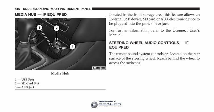
MEDIA HUB — IF EQUIPPED Located in the front storage area, this feature allows anExternal USB device, SD card or AUX electronic device tobe plugged into the port, slot or jack.
For further information, refer to the Uconnect User’sManual.
STEERING WHEEL AUDIO CONTROLS — IFEQUIPPED
The remote sound system controls are located on the rearsurface of the steering wheel. Reach behind the wheel toaccess the switches.
Media Hub
1 — USB Port2 — SD Card Slot3 — AUX Jack
416 UNDERSTANDING YOUR INSTRUMENT PANEL
Information Provided by:
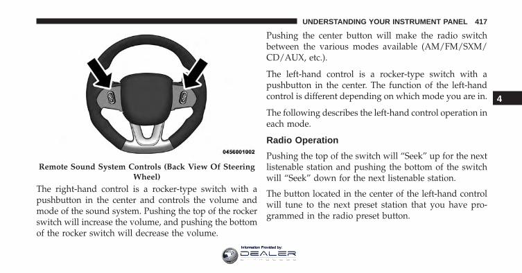
The right-hand control is a rocker-type switch with apushbutton in the center and controls the volume andmode of the sound system. Pushing the top of the rockerswitch will increase the volume, and pushing the bottomof the rocker switch will decrease the volume.
Pushing the center button will make the radio switchbetween the various modes available (AM/FM/SXM/CD/AUX, etc.).
The left-hand control is a rocker-type switch with apushbutton in the center. The function of the left-handcontrol is different depending on which mode you are in.
The following describes the left-hand control operation ineach mode.
Radio Operation
Pushing the top of the switch will “Seek” up for the nextlistenable station and pushing the bottom of the switchwill “Seek” down for the next listenable station.
The button located in the center of the left-hand controlwill tune to the next preset station that you have pro-grammed in the radio preset button.
Remote Sound System Controls (Back View Of SteeringWheel)
4
UNDERSTANDING YOUR INSTRUMENT PANEL 417
Information Provided by:
CD Player
Pushing the top of the switch once will go to the nexttrack on the CD. Pushing the bottom of the switch oncewill go to the beginning of the current track, or to thebeginning of the previous track if it is within eightseconds after the current track begins to play.
If you push the switch up or down twice, it plays thesecond track; three times, it will play the third, etc.
The center button on the left side rocker switch has nofunction for a single-disc CD player. However, when amultiple-disc CD player is equipped on the vehicle, thecenter button will select the next available CD in theplayer.
CD/DVD DISC MAINTENANCE
To keep a CD/DVD in good condition, take the followingprecautions:
1. Handle the disc by its edge; avoid touching thesurface.
2. If the disc is stained, clean the surface with a soft cloth,wiping from center to edge.
3. Do not apply paper or tape to the disc; avoid scratch-ing the disc.
4. Do not use solvents such as benzene, thinner, cleaners,or anti-static sprays.
5. Store the disc in its case after playing.
6. Do not expose the disc to direct sunlight.
7. Do not store the disc where temperatures may becometoo high.
418 UNDERSTANDING YOUR INSTRUMENT PANEL
Information Provided by:
NOTE: If you experience difficulty in playing a particulardisc, it may be damaged (e.g., scratched, reflective coat-ing removed, a hair, moisture or dew on the disc)oversized, or have protection encoding. Try a knowngood disc before considering disc player service.
RADIO OPERATION AND MOBILE DEVICES
Under certain conditions, the mobile device being on inyour vehicle can cause erratic or noisy performance fromyour radio. This condition may be lessened or eliminatedby relocating the mobile device antenna. This condition isnot harmful to the radio. If your radio performance doesnot satisfactorily “clear” by the repositioning of theantenna, it is recommended that the radio volume beturned down or off during mobile device operation whennot using Uconnect (if equipped).
Regulatory And Safety Information
USA/CANADA
Exposure to Radio Frequency Radiation
The radiated output power of the internal wireless radiois far below the FCC radio frequency exposure limits.Nevertheless, the wireless radio will be used in such amanner that the radio is 20 cm or further from the humanbody.
The internal wireless radio operates within guidelinesfound in radio frequency safety standards and recom-mendations, which reflect the consensus of the scientificcommunity.
The radio manufacturer believes the internal wirelessradio is safe for use by consumers. The level of energyemitted is far less than the electromagnetic energy emit-ted by wireless devices such as mobile phones. However,the use of wireless radios may be restricted in some
4
UNDERSTANDING YOUR INSTRUMENT PANEL 419
Information Provided by:
situations or environments, such as aboard airplanes. Ifyou are unsure of restrictions, you are encouraged to askfor authorization before turning on the wireless radio.
This device complies with Part 15 of the FCC Rules andwith Industry Canada license-exempt RSS standard(s).Operation is subject to the following two conditions:
1. This device may not cause harmful interference.
2. This device must accept any interference received,including interference that may cause undesired op-eration.
NOTE:
• This equipment has been tested and found to complywith the limits for a Class B digital device, pursuant toPart 15 of the FCC Rules. These limits are designed toprovide reasonable protection against harmful inter-ference in a residential installation. This equipmentgenerates, uses and can radiate radio frequency energyand, if not installed and used in accordance with theinstructions, may cause harmful interference to radiocommunications. However, there is no guarantee thatinterference will not occur in a particular installation.
• If this equipment does cause harmful interference toradio or television reception, which can be determinedby turning the equipment off and on, the user isencouraged to try to correct the interference by one ormore of the following measures:
• Increase the separation between the equipment andreceiver.
420 UNDERSTANDING YOUR INSTRUMENT PANEL
Information Provided by:
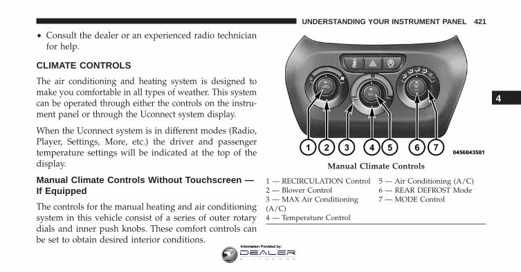
• Consult the dealer or an experienced radio technicianfor help.
CLIMATE CONTROLS
The air conditioning and heating system is designed tomake you comfortable in all types of weather. This systemcan be operated through either the controls on the instru-ment panel or through the Uconnect system display.
When the Uconnect system is in different modes (Radio,Player, Settings, More, etc.) the driver and passengertemperature settings will be indicated at the top of thedisplay.
Manual Climate Controls Without Touchscreen —If Equipped
The controls for the manual heating and air conditioningsystem in this vehicle consist of a series of outer rotarydials and inner push knobs. These comfort controls canbe set to obtain desired interior conditions.
Manual Climate Controls
1 — RECIRCULATION Control 5 — Air Conditioning (A/C)2 — Blower Control 6 — REAR DEFROST Mode3 — MAX Air Conditioning(A/C)
7 — MODE Control
4 — Temperature Control
4
UNDERSTANDING YOUR INSTRUMENT PANEL 421
Information Provided by:
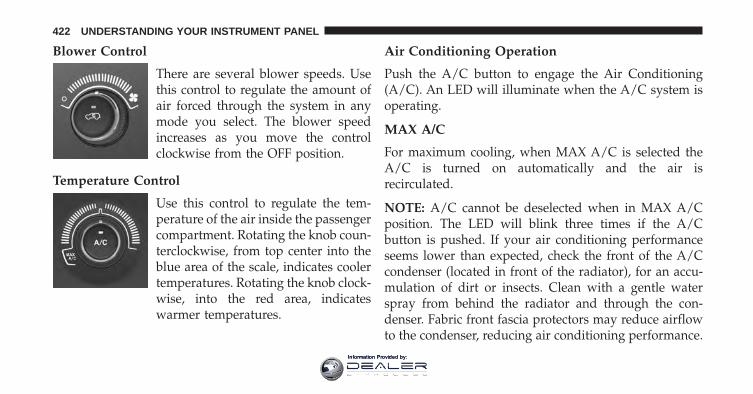
Blower Control
There are several blower speeds. Usethis control to regulate the amount ofair forced through the system in anymode you select. The blower speedincreases as you move the controlclockwise from the OFF position.
Temperature Control
Use this control to regulate the tem-perature of the air inside the passengercompartment. Rotating the knob coun-terclockwise, from top center into theblue area of the scale, indicates coolertemperatures. Rotating the knob clock-wise, into the red area, indicateswarmer temperatures.
Air Conditioning Operation
Push the A/C button to engage the Air Conditioning(A/C). An LED will illuminate when the A/C system isoperating.
MAX A/C
For maximum cooling, when MAX A/C is selected theA/C is turned on automatically and the air isrecirculated.
NOTE: A/C cannot be deselected when in MAX A/Cposition. The LED will blink three times if the A/Cbutton is pushed. If your air conditioning performanceseems lower than expected, check the front of the A/Ccondenser (located in front of the radiator), for an accu-mulation of dirt or insects. Clean with a gentle waterspray from behind the radiator and through the con-denser. Fabric front fascia protectors may reduce airflowto the condenser, reducing air conditioning performance.
422 UNDERSTANDING YOUR INSTRUMENT PANEL
Information Provided by:
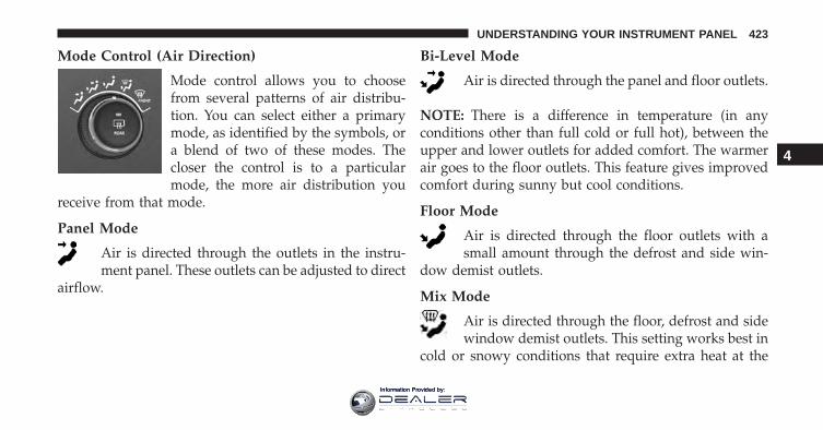
Mode Control (Air Direction)
Mode control allows you to choosefrom several patterns of air distribu-tion. You can select either a primarymode, as identified by the symbols, ora blend of two of these modes. Thecloser the control is to a particularmode, the more air distribution you
receive from that mode.
Panel Mode
Air is directed through the outlets in the instru-ment panel. These outlets can be adjusted to direct
airflow.
Bi-Level Mode
Air is directed through the panel and floor outlets.
NOTE: There is a difference in temperature (in anyconditions other than full cold or full hot), between theupper and lower outlets for added comfort. The warmerair goes to the floor outlets. This feature gives improvedcomfort during sunny but cool conditions.
Floor Mode
Air is directed through the floor outlets with asmall amount through the defrost and side win-
dow demist outlets.
Mix Mode
Air is directed through the floor, defrost and sidewindow demist outlets. This setting works best in
cold or snowy conditions that require extra heat at the
4
UNDERSTANDING YOUR INSTRUMENT PANEL 423
Information Provided by:
windshield. This setting is good for maintaining comfort,while reducing moisture on the windshield.
Defrost Mode
Air is directed through the windshield and sidewindow demist outlets. Use the DEFROST mode
with maximum blower and warm temperature settingsfor best windshield and side window defrosting.
NOTE: The air conditioning compressor operates in MIXand DEFROST, or a blend of these modes even if the A/Cbutton is not pushed. This dehumidifies the air to helpdry the windshield. To improve fuel economy, use thesemodes only when necessary.
Recirculation Control
Push this button to choose between outside air intake orrecirculation of the air inside the vehicle. A LED willilluminate when you are in Recirculation mode. Only usethe Recirculation mode to temporarily block out any
outside odors, smoke, or dust, and to cool the interiorrapidly upon initial start-up in very hot or humidweather.
NOTE:
• If the RECIRCULATION button is pushed when thesystem is in Defrost mode the Recirculation LEDindicator will flash three times and then turn off toindicate Recirculation mode is not allowed.
• Continuous use of the Recirculation mode may makethe inside air stuffy and window fogging may occur.Extended use of this mode is not recommended.
• In cold or damp weather, the use of the Recirculationmode will cause windows to fog on the inside becauseof moisture buildup inside the vehicle. For maximumdefogging, select the outside air position.
424 UNDERSTANDING YOUR INSTRUMENT PANEL
Information Provided by:
• The A/C can be deselected manually without disturb-ing the mode control selection by pushing the A/Cbutton.
Air Outlets
The airflow from each of the instrument panel outlets canbe adjusted for direction, and turned on or off to controlairflow.
NOTE: For maximum airflow to the rear, the centerinstrument panel outlets can be directed toward the rearseat passengers.
Economy Mode
If ECONOMY mode is desired, push the A/C button toturn off the LED indicator and the A/C compressor.Rotate the temperature control knob to the desired tem-perature. Also, make sure to select only Panel, Bi-Level orFloor modes.
Stop/Start System — If Equipped
While in an Autostop, the Climate Controls system mayautomatically adjust airflow to maintain cabin comfort.Customer settings will be maintained upon return to anengine running condition.
Windshield Wiper De-icer — If Equipped
The windshield wiper de-icer is a heating element lo-cated at the base of the windshield.
The windshield wiper de-icer operates automaticallyonce the following conditions are met:
• Activation By Front Defrost
The wiper de-icer activates automatically during a coldweather manual start with full defrost, and when theambient temperature is below 33° F (0.6° C).
4
UNDERSTANDING YOUR INSTRUMENT PANEL 425
Information Provided by:
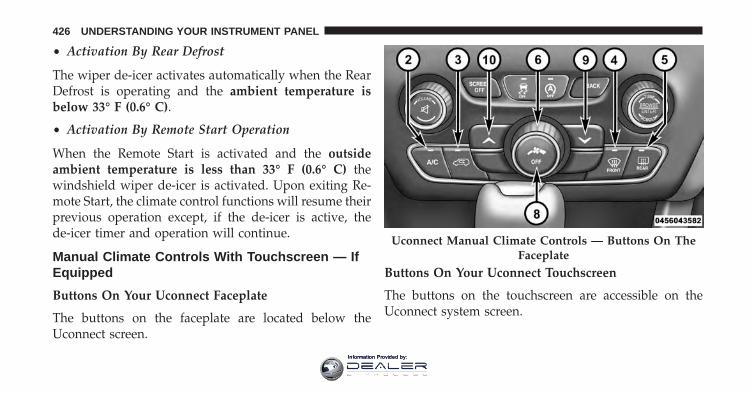
• Activation By Rear Defrost
The wiper de-icer activates automatically when the RearDefrost is operating and the ambient temperature isbelow 33° F (0.6° C).
• Activation By Remote Start Operation
When the Remote Start is activated and the outsideambient temperature is less than 33° F (0.6° C) thewindshield wiper de-icer is activated. Upon exiting Re-mote Start, the climate control functions will resume theirprevious operation except, if the de-icer is active, thede-icer timer and operation will continue.
Manual Climate Controls With Touchscreen — IfEquipped
Buttons On Your Uconnect Faceplate
The buttons on the faceplate are located below theUconnect screen.
Buttons On Your Uconnect Touchscreen
The buttons on the touchscreen are accessible on theUconnect system screen.
Uconnect Manual Climate Controls — Buttons On TheFaceplate
426 UNDERSTANDING YOUR INSTRUMENT PANEL
Information Provided by:
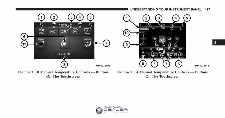
Uconnect 5.0 Manual Temperature Controls — ButtonsOn The Touchscreen
Uconnect 8.4 Manual Temperature Controls — ButtonsOn The Touchscreen
4
UNDERSTANDING YOUR INSTRUMENT PANEL 427
Information Provided by:
Button Descriptions (Applies To Both The Buttons OnYour Faceplate And The Buttons On Your Touchscreen)
1. MAX A/C Button
Push and release to change the current setting, theindicator illuminates when MAX A/C is ON. Performingthis function again will cause the MAX A/C operation toswitch into manual mode and the MAX A/C indicatorwill turn off.
2. A/C Button
Push and release to change the current setting, theindicator illuminates when A/C is ON. Performing thisfunction again will cause the A/C operation to switchinto manual mode and the A/C indicator will turn off.
3. Recirculation Button
Push and release to change the current setting, theindicator illuminates when ON.
4. Front Defrost Button
Push and release to change the current airflow setting toDefrost mode. The indicator illuminates when this fea-ture is ON. Air comes from the windshield and sidewindow demist outlets. When the defrost button isselected, the blower level will increase. Use Defrost modewith maximum temperature settings for best windshieldand side window defrosting and defogging.
5. Rear Defrost Button
Push and release this button to turn on the rear windowdefroster and the heated outside mirrors (if equipped).An indicator will illuminate when the rear windowdefroster is on. The rear window defroster automaticallyturns off after 10 minutes. For each additional push ofthis button, five additional minutes will be added to thetimer function.
428 UNDERSTANDING YOUR INSTRUMENT PANEL
Information Provided by:
CAUTION!
Failure to follow these cautions can cause damage tothe heating elements:• Use care when washing the inside of the rear
window. Do not use abrasive window cleaners onthe interior surface of the window. Use a soft clothand a mild washing solution, wiping parallel to theheating elements. Labels can be peeled off aftersoaking with warm water.
• Do not use scrapers, sharp instruments, or abrasivewindow cleaners on the interior surface of thewindow.
• Keep all objects a safe distance from the window.
6. Blower Control
Blower control is used to regulate the amount of airforced through the climate system. There are sevenblower speeds available. Adjusting the blower will cause
automatic mode to switch to manual operation. Thespeeds can be selected using either the blower controlknob on the faceplate or buttons on the touchscreen asfollows:
Blower Control Knob On The Faceplate
The blower speed increases as you turn the blowercontrol knob clockwise from the lowest blower setting.The blower speed decreases as you turn the blowercontrol knob counterclockwise.
Buttons On The Touchscreen
Use the small blower icon to reduce the blower settingand the large blower icon to increase the blower setting.Blower can also be selected by pressing the blower bararea between the icons.
4
UNDERSTANDING YOUR INSTRUMENT PANEL 429
Information Provided by:
7. Modes
The airflow distribution mode can be adjusted so aircomes from the instrument panel outlets, floor outlets,and demist outlets. The Mode settings are as follows:
• Panel Mode
Air comes from the outlets in the instrumentpanel. Each of these outlets can be individually
adjusted to direct the flow of air. The air vanes of thecenter outlets and outboard outlets can be moved up anddown or side to side to regulate airflow direction. Thereis a shut off wheel located below the air vanes to shut offor adjust the amount of airflow from these outlets.
• Bi-Level Mode
Air comes from the instrument panel outlets andfloor outlets. A slight amount of air is directed
through the defrost and side window demister outlets.
NOTE: BI-LEVEL mode is designed under comfort con-ditions to provide cooler air out of the panel outlets andwarmer air from the floor outlets.
• Floor Mode
Air comes from the floor outlets. A slight amountof air is directed through the defrost and side
window demister outlets.
• Mix Mode
Air comes from the floor, defrost and side windowdemist outlets. This mode works best in cold or
snowy conditions.
NOTE: The air conditioning compressor operates in MIXand DEFROST modes even if the A/C button is notpushed. This dehumidifies the air to help dry the wind-shield. To improve fuel economy, use these modes onlywhen necessary.
430 UNDERSTANDING YOUR INSTRUMENT PANEL
Information Provided by:
8. Climate Control OFF Button
Push and release this button to turn the Climate ControlON/OFF.
9. Temperature Control Down Button (Uconnect 8.4)
Provides temperature control. Push the button on thefaceplate for cooler temperature settings or on the touch-screen, press and slide the button on the touchscreentemperature bar towards the blue arrow button on thetouchscreen for cooler temperature settings.
10. Temperature Control Up Button (Uconnect 8.4)
Provides temperature control. Push the button on thefaceplate for warmer temperature settings or on thetouchscreen, press and slide the button on the touch-screen temperature bar towards the red arrow button onthe touchscreen for warmer temperature settings.
11. Temperature Control (Uconnect 5.0)
Press the temperature button on the touchscreen toregulate the temperature of the air inside the passengercompartment. Moving the temperature bar into the redarea, indicates warmer temperatures. Moving the tem-perature bar into the blue area indicates cooler tempera-tures.
Windshield Wiper De-icer — If Equipped
The windshield wiper de-icer is a heating element lo-cated at the base of the windshield.
The windshield wiper de-icer operates automaticallyonce the following conditions are met:
• Activation By Front Defrost
The wiper de-icer activates automatically during a coldweather manual start with full defrost, and when theambient temperature is below 33° F (0.6° C).
4
UNDERSTANDING YOUR INSTRUMENT PANEL 431
Information Provided by:
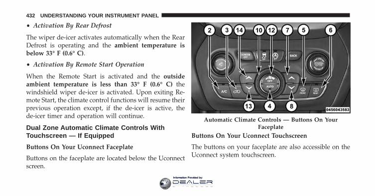
• Activation By Rear Defrost
The wiper de-icer activates automatically when the RearDefrost is operating and the ambient temperature isbelow 33° F (0.6° C).
• Activation By Remote Start Operation
When the Remote Start is activated and the outsideambient temperature is less than 33° F (0.6° C) thewindshield wiper de-icer is activated. Upon exiting Re-mote Start, the climate control functions will resume theirprevious operation except, if the de-icer is active, thede-icer timer and operation will continue.
Dual Zone Automatic Climate Controls WithTouchscreen — If Equipped
Buttons On Your Uconnect Faceplate
Buttons on the faceplate are located below the Uconnectscreen.
Buttons On Your Uconnect Touchscreen
The buttons on your faceplate are also accessible on theUconnect system touchscreen.
Automatic Climate Controls — Buttons On YourFaceplate
432 UNDERSTANDING YOUR INSTRUMENT PANEL
Information Provided by:
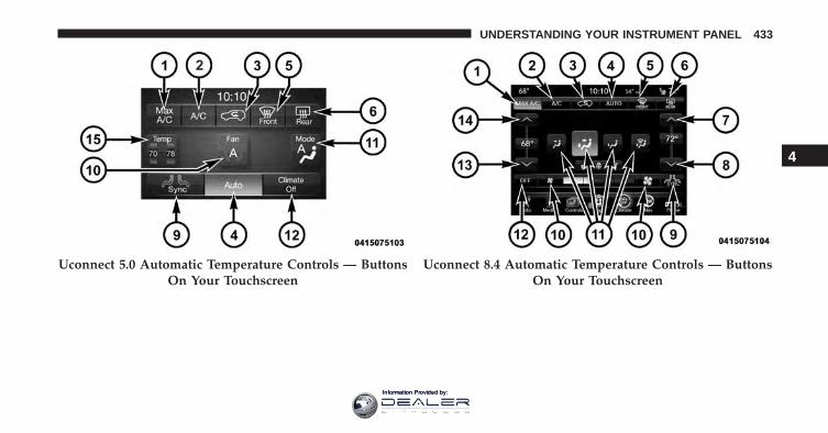
Uconnect 5.0 Automatic Temperature Controls — ButtonsOn Your Touchscreen
Uconnect 8.4 Automatic Temperature Controls — ButtonsOn Your Touchscreen
4
UNDERSTANDING YOUR INSTRUMENT PANEL 433
Information Provided by:
Button Descriptions (Applies To Both The Buttons OnYour Faceplate And The Buttons On Your Touchscreen)
1. MAX A/C Button
Press and release to change the current setting, theindicator illuminates when MAX A/C is ON. Performingthis function again will cause the MAX A/C operation toswitch into manual mode and the MAX A/C indicatorwill turn off.
2. A/C Button
Press and release to change the current setting, theindicator illuminates when A/C is ON. Performing thisfunction again will cause the A/C operation to switchinto manual mode and the A/C indicator will turn off.
3. Recirculation Button
Press and release to change the current setting, theindicator illuminates when ON.
4. AUTO Operation Button
Automatically controls the interior cabin temperature byadjusting airflow distribution and amount. Performingthis function will cause the system to switch betweenmanual mode and automatic modes. Refer to “AutomaticOperation” for more information.
5. Front Defrost Button
Press and release to change the current airflow setting toDefrost mode. The indicator illuminates when this fea-ture is ON. Air comes from the windshield and side
434 UNDERSTANDING YOUR INSTRUMENT PANEL
Information Provided by:
window demist outlets. When the defrost button isselected, the blower level will increase. Use Defrost modewith maximum temperature settings for best windshieldand side window defrosting and defogging. Performingthis function will cause the ATC to switch into manualmode. If the front defrost mode is turned off the climatesystem will return to the previous setting.
6. Rear Defrost Button
Press and release this button to turn on the rear windowdefroster and the heated outside mirrors (if equipped).An indicator will illuminate when the rear windowdefroster is on. The rear window defroster automaticallyturns off after 10 minutes. For each additional press ofthis button, five additional minutes will be added to thetimer function.
CAUTION!
Failure to follow these cautions can cause damage tothe heating elements:• Use care when washing the inside of the rear
window. Do not use abrasive window cleaners onthe interior surface of the window. Use a soft clothand a mild washing solution, wiping parallel to theheating elements. Labels can be peeled off aftersoaking with warm water.
• Do not use scrapers, sharp instruments, or abrasivewindow cleaners on the interior surface of thewindow.
• Keep all objects a safe distance from the window.
4
UNDERSTANDING YOUR INSTRUMENT PANEL 435
Information Provided by:
7. Passenger Temperature Control Up Button (Uconnect8.4 Only)
Provides the passenger with independent temperaturecontrol. Push the button on the faceplate for warmertemperature settings or on the touchscreen, press andslide the button on the touchscreen temperature bartowards the red arrow button on the touchscreen forwarmer temperature settings.
NOTE: Pressing this button while in Sync mode willautomatically exit Sync.
8. Passenger Temperature Control Down Button(Uconnect 8.4 Only)
Provides the passenger with independent temperaturecontrol. Push the button on the faceplate for coolertemperature settings or on the touchscreen, press and
slide the button on the touchscreen temperature bartowards the blue arrow button on the touchscreen forcooler temperature settings.
NOTE: Pressing this button while in Sync mode willautomatically exit Sync.
9. SYNC
Press the Sync button on the touchscreen to toggle theSync feature On/Off. The Sync indicator is illuminatedwhen this feature is enabled. Sync is used to synchronizethe passenger temperature setting with the driver tem-perature setting. Changing the passenger temperaturesetting while in Sync will automatically exit this feature.
436 UNDERSTANDING YOUR INSTRUMENT PANEL
Information Provided by:
10. Blower Control
Blower control is used to regulate the amount of airforced through the climate system. There are sevenblower speeds available. Adjusting the blower will causeautomatic mode to switch to manual operation. Thespeeds can be selected using either the blower controlknob on the faceplate or buttons on the touchscreen asfollows:
Blower Control Knob On The Faceplate
The blower speed increases as you turn the blowercontrol knob clockwise from the lowest blower setting.The blower speed decreases as you turn the blowercontrol knob counterclockwise.
Button On The Touchscreen
Use the small blower icon to reduce the blower settingand the large blower icon to increase the blower setting.Blower can also be selected by pressing the blower bararea between the icons.
11. Modes
The airflow distribution mode can be adjusted so aircomes from the instrument panel outlets, floor outlets,and demist outlets. The Mode settings are as follows:
• Panel Mode
Air comes from the outlets in the instrumentpanel. Each of these outlets can be individually
adjusted to direct the flow of air. The air vanes of thecenter outlets and outboard outlets can be moved up anddown or side to side to regulate airflow direction. Thereis a shut off wheel located below the air vanes to shut offor adjust the amount of airflow from these outlets.
4
UNDERSTANDING YOUR INSTRUMENT PANEL 437
Information Provided by:
• Bi-Level Mode
Air comes from the instrument panel outlets andfloor outlets. A slight amount of air is directed
through the defrost and side window demister outlets.
NOTE: Bi-Level mode is designed under comfort condi-tions to provide cooler air out of the panel outlets andwarmer air from the floor outlets.
• Floor Mode
Air comes from the floor outlets. A slight amountof air is directed through the defrost and side
window demister outlets.
• Mix Mode
Air comes from the floor, defrost and side windowdemist outlets. This mode works best in cold or
snowy conditions.
12. Climate Control OFF Button
Press and release this button to turn the Climate ControlON/OFF.
13. Driver Temperature Control Down Button (Uconnect8.4 Only)
Provides the driver with independent temperature con-trol. Push the button on the faceplate for cooler tempera-ture settings or on the touchscreen, press and slide thebutton on the touchscreen temperature bar towards theblue arrow button on the touchscreen for cooler tempera-ture settings.
NOTE: In Sync mode, this button will also automaticallyadjust the passenger temperature setting at the sametime.
438 UNDERSTANDING YOUR INSTRUMENT PANEL
Information Provided by:
14. Driver Temperature Control Up Button (Uconnect 8.4Only)
Provides the driver with independent temperature con-trol. Push the button on the faceplate for warmer tem-perature settings or on the touchscreen, press and slidethe button on the touchscreen temperature bar towardsthe red arrow button on the touchscreen for warmertemperature settings.
NOTE: In Sync mode, this button will also automaticallyadjust the passenger temperature setting at the sametime.
15. Temperature Control (Uconnect 5.0 Only)
Press the temperature button on the touchscreen to regu-late the temperature of the air inside the passenger com-partment. Moving the temperature bar into the red area,indicates warmer temperatures. Moving the temperaturebar into the blue area indicates cooler temperatures.
Climate Control Functions
A/C (Air Conditioning)
The Air Conditioning (A/C) button allows the operatorto manually activate or deactivate the air conditioningsystem. When the air conditioning system is turned on,cool dehumidified air will flow through the outlets intothe cabin. For improved fuel economy, push the A/Cbutton to turn off the air conditioning and manuallyadjust the blower and airflow mode settings. Also, makesure to select only Panel, Bi-Level or Floor modes.
NOTE:
• If fog or mist appears on the windshield or side glass,select Defrost mode and adjust blower speed ifneeded.
• If your air conditioning performance seems lower thanexpected, check the front of the A/C condenser (lo-cated in front of the radiator), for an accumulation of
4
UNDERSTANDING YOUR INSTRUMENT PANEL 439
Information Provided by:
dirt or insects. Clean with a gentle water spray frombehind the radiator and through the condenser. Fabricfront fascia protectors may reduce airflow to thecondenser, reducing air conditioning performance.
MAX A/C
MAX A/C sets the control for maximum cooling perfor-mance.
Press to toggle between MAX A/C and the prior settings.The button on the touchscreen illuminates when MAXA/C is ON.
In MAX A/C, the blower level and mode position can beadjusted to desired user settings. Pushing other settingswill cause the MAX A/C operation to switch to theselected setting and cause MAX A/C to exit.
Recirculation
When outside air contains smoke, odors, orhigh humidity, or if rapid cooling is desired,you may wish to recirculate interior air bypressing the Recirculation control button. The
recirculation indicator will illuminate when this button isselected. Press the button a second time to turn off theRecirculation mode and allow outside air into the vehicle.
NOTE: In cold weather, use of Recirculation mode maylead to excessive window fogging. The recirculationfeature may be unavailable (button on the touchscreengreyed out) if conditions exist that could create foggingon the inside of the windshield. On systems with ManualClimate Controls, the Recirculation mode is not allowedin Defrost mode to improve window clearing operation.
440 UNDERSTANDING YOUR INSTRUMENT PANEL
Information Provided by:
Recirculation will be disabled automatically if this modeis selected. Attempting to use Recirculation while in thismode will cause the LED in the control button to blinkand then turn off.
Automatic Temperature Control (ATC)
Automatic Operation
1. Push the AUTO button on the faceplate or press the“AUTO” button on the touchscreen.
2. Adjust the temperature you would like the system tomaintain by adjusting the driver and passenger tem-perature buttons on the faceplate or buttons on thetouchscreen. Once the desired temperature is dis-played, the system will achieve and automaticallymaintain that comfort level.
3. When the system is set up for your comfort level, it isnot necessary to change the temperature. You willexperience the greatest efficiency by simply allowingthe system to function automatically.
NOTE:
• It is not necessary to move the temperature settings.The system automatically adjusts the temperature,mode, and blower speed to provide comfort as quicklyas possible.
• The temperature can be displayed in U.S. or Metricunits by selecting the Uconnect customer-programmable feature. Refer to the “Uconnect SystemSettings” in this section of the manual.
To provide you with maximum comfort in the Automaticmode, during cold start-ups the blower fan will remainon low until the engine warms up. The blower willincrease in speed and transition into Auto mode.
4
UNDERSTANDING YOUR INSTRUMENT PANEL 441
Information Provided by:
Manual Operation Override
The system allows for manual selection of blower speed,air distribution mode, A/C status and recirculation con-trol.
The blower fan speed can be set to any fixed speed byadjusting the blower control. The fan will now operate ata fixed speed until additional speeds are selected. Thisallows the front occupants to control the volume of aircirculated in the vehicle and cancel the Auto mode.
The operator can also select the direction of the airflowby selecting one of the available mode settings. A/Coperation and Recirculation control can also be manuallyselected in Manual operation.
NOTE: Each of these features operates independentlyfrom each other. If any feature is controlled manually,temperature control will continue to operate automati-cally.
Operating Tips
NOTE: Refer to the chart at the end of this section forsuggested control settings for various weather condi-tions.
Summer Operation
The engine cooling system must be protected with ahigh-quality antifreeze coolant to provide proper corro-sion protection and to protect against engine overheating.A solution of 50% OAT (Organic Additive Technology)coolant that meets the requirements of FCA MaterialStandard MS.90032 and 50% water is recommended.Refer to “Maintenance Procedures” in “Maintaining YourVehicle” for proper coolant selection.
Winter Operation
Use of the air Recirculation mode during winter monthsis not recommended because it may cause windowfogging.
442 UNDERSTANDING YOUR INSTRUMENT PANEL
Information Provided by:
Vacation Storage
Any time you store your vehicle or keep it out of service(i.e., vacation) for two weeks or more, run the airconditioning system at idle for about five minutes in thefresh air and high blower setting. This will ensureadequate system lubrication to minimize the possibilityof compressor damage when the system is started again.
Window Fogging
Interior fogging on the windshield can be quickly re-moved by turning the mode selector to Defrost. TheDefrost/Floor mode can be used to maintain a clearwindshield and provide sufficient heating. If side win-dow fogging becomes objectionable, increase blowerspeed to improve airflow and clearing of the side win-dows. Vehicle windows tend to fog on the inside in mildbut rainy or humid weather.
NOTE:
• Recirculate without A/C should not be used for longperiods, as fogging may occur.
• Automatic Temperature Controls (ATC) will automati-cally adjust the climate control settings to reduce oreliminate window fogging on the front windshield.When this occurs, recirculation will be unavailable.
Windshield Wiper De-icer — If Equipped
The windshield wiper de-icer is a heating element lo-cated at the base of the windshield.
4
UNDERSTANDING YOUR INSTRUMENT PANEL 443
Information Provided by:
The windshield wiper de-icer operates automaticallyonce the following conditions are met:
• Activation By Front Defrost
The wiper de-icer activates automatically during a coldweather manual start with full defrost, and when theambient temperature is below 33° F (0.6° C).
• Activation By Rear Defrost
The wiper de-icer activates automatically when the RearDefrost is operating and the ambient temperature isbelow 33° F (0.6° C).
• Activation By Remote Start Operation
When the Remote Start is activated and the outsideambient temperature is less than 33° F (0.6° C) thewindshield wiper de-icer is activated. Upon exiting Re-mote Start, the climate control functions will resume theirprevious operation except, if the de-icer is active, thede-icer timer and operation will continue.
Outside Air Intake
Make sure the air intake, located directly in front of thewindshield, is free of obstructions such as leaves. Leavescollected in the air intake may reduce airflow, and if theyenter the plenum, they could plug the water drains. Inwinter months, make sure the air intake is clear of ice,slush, and snow.
A/C Air Filter
The climate control system filters outside air containingdust, pollen and some odors. Strong odors cannot be totallyfiltered out. Refer to “Maintenance Procedures” in “Main-taining Your Vehicle” for filter replacement instructions.
444 UNDERSTANDING YOUR INSTRUMENT PANEL
Information Provided by:
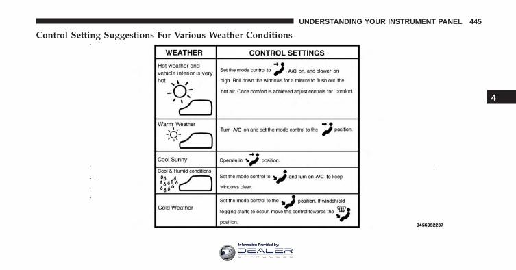
Control Setting Suggestions For Various Weather Conditions
4
UNDERSTANDING YOUR INSTRUMENT PANEL 445
Information Provided by:
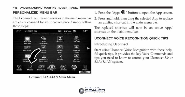
PERSONALIZED MENU BAR
The Uconnect features and services in the main menu barare easily changed for your convenience. Simply followthese steps:
1. Press the “Apps ” button to open the App screen.
2. Press and hold, then drag the selected App to replacean existing shortcut in the main menu bar.
The replaced shortcut will now be an active App/shortcut on the main menu bar.
UCONNECT VOICE RECOGNITION QUICK TIPS
Introducing Uconnect
Start using Uconnect Voice Recognition with these help-ful quick tips. It provides the key Voice Commands andtips you need to know to control your Uconnect 5.0 or8.4A/8.4AN system.
Uconnect 8.4A/8.4AN Main Menu
446 UNDERSTANDING YOUR INSTRUMENT PANEL
Information Provided by:
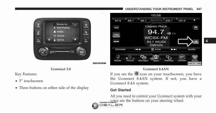
Key Features:
• 5” touchscreen
• Three buttons on either side of the display
If you see the icon on your touchscreen, you havethe Uconnect 8.4AN system. If not, you have aUconnect 8.4A system.
Get Started
All you need to control your Uconnect system with yourvoice are the buttons on your steering wheel.
Uconnect 5.0 Uconnect 8.4AN
4
UNDERSTANDING YOUR INSTRUMENT PANEL 447
Information Provided by:
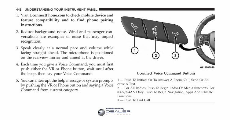
1. Visit UconnectPhone.com to check mobile device andfeature compatibility and to find phone pairinginstructions.
2. Reduce background noise. Wind and passenger con-versations are examples of noise that may impactrecognition.
3. Speak clearly at a normal pace and volume whilefacing straight ahead. The microphone is positionedon the rearview mirror and aimed at the driver.
4. Each time you give a Voice Command, you must firstpush either the VR or Phone button, wait until afterthe beep, then say your Voice Command.
5. You can interrupt the help message or system promptsby pushing the VR or Phone button and saying a VoiceCommand from current category.
Uconnect Voice Command Buttons
1 — Push To Initiate Or To Answer A Phone Call, Send Or Re-ceive A Text2 — For All Radios: Push To Begin Radio Or Media functions. For8.4A/8.4AN Only: Push To Begin Navigation, Apps And ClimateFunctions.3 — Push To End Call
448 UNDERSTANDING YOUR INSTRUMENT PANEL
Information Provided by:
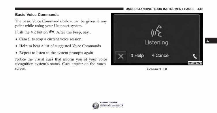
Basic Voice Commands
The basic Voice Commands below can be given at anypoint while using your Uconnect system.
Push the VR button . After the beep, say�
• Cancel to stop a current voice session
• Help to hear a list of suggested Voice Commands
• Repeat to listen to the system prompts again
Notice the visual cues that inform you of your voicerecognition system’s status. Cues appear on the touch-screen. Uconnect 5.0
4
UNDERSTANDING YOUR INSTRUMENT PANEL 449
Information Provided by:
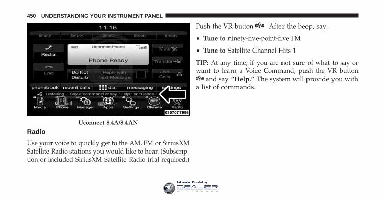
Radio
Use your voice to quickly get to the AM, FM or SiriusXMSatellite Radio stations you would like to hear. (Subscrip-tion or included SiriusXM Satellite Radio trial required.)
Push the VR button . After the beep, say�
• Tune to ninety-five-point-five FM
• Tune to Satellite Channel Hits 1
TIP: At any time, if you are not sure of what to say orwant to learn a Voice Command, push the VR button
and say “Help.” The system will provide you witha list of commands.
Uconnect 8.4A/8.4AN
450 UNDERSTANDING YOUR INSTRUMENT PANEL
Information Provided by:
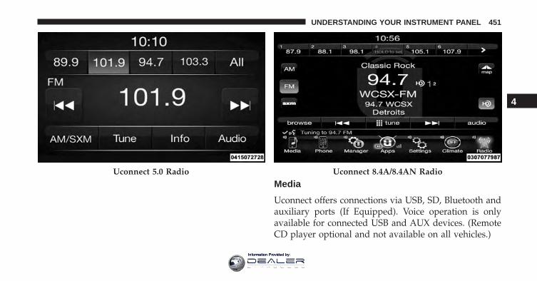
Media
Uconnect offers connections via USB, SD, Bluetooth andauxiliary ports (If Equipped). Voice operation is onlyavailable for connected USB and AUX devices. (RemoteCD player optional and not available on all vehicles.)
Uconnect 5.0 Radio Uconnect 8.4A/8.4AN Radio
4
UNDERSTANDING YOUR INSTRUMENT PANEL 451
Information Provided by:
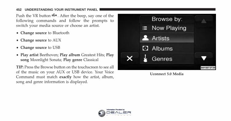
Push the VR button . After the beep, say one of thefollowing commands and follow the prompts toswitch your media source or choose an artist.
• Change source to Bluetooth
• Change source to AUX
• Change source to USB
• Play artist Beethoven; Play album Greatest Hits; Playsong Moonlight Sonata; Play genre Classical
TIP: Press the Browse button on the touchscreen to see allof the music on your AUX or USB device. Your VoiceCommand must match exactly how the artist, album,song and genre information is displayed.
Uconnect 5.0 Media
452 UNDERSTANDING YOUR INSTRUMENT PANEL
Information Provided by:
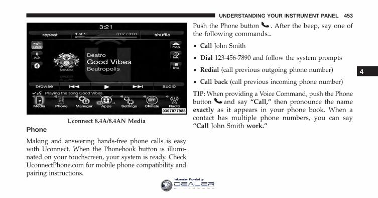
Phone
Making and answering hands-free phone calls is easywith Uconnect. When the Phonebook button is illumi-nated on your touchscreen, your system is ready. CheckUconnectPhone.com for mobile phone compatibility andpairing instructions.
Push the Phone button . After the beep, say one ofthe following commands�
• Call John Smith
• Dial 123-456-7890 and follow the system prompts
• Redial (call previous outgoing phone number)
• Call back (call previous incoming phone number)
TIP: When providing a Voice Command, push the Phonebutton and say “Call,” then pronounce the nameexactly as it appears in your phone book. When acontact has multiple phone numbers, you can say“Call John Smith work.”
Uconnect 8.4A/8.4AN Media
4
UNDERSTANDING YOUR INSTRUMENT PANEL 453
Information Provided by:
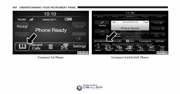
Uconnect 5.0 Phone Uconnect 8.4A/8.4AN Phone
454 UNDERSTANDING YOUR INSTRUMENT PANEL
Information Provided by:
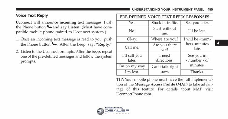
Voice Text Reply
Uconnect will announce incoming text messages. Pushthe Phone button and say Listen. (Must have com-patible mobile phone paired to Uconnect system.)
1. Once an incoming text message is read to you, pushthe Phone button . After the beep, say: “Reply.”
2. Listen to the Uconnect prompts. After the beep, repeatone of the pre-defined messages and follow the systemprompts.
PRE-DEFINED VOICE TEXT REPLY RESPONSESYes. Stuck in traffic. See you later.
No. Start withoutme. I’ll be late.
Okay. Where are you? I will be <num-ber> minutes
late.Call me. Are you thereyet?
I’ll call youlater.
I needdirections.
See you in<number> of
minutes.I’m on my way. Can’t talk rightnow.I’m lost. Thanks.
TIP: Your mobile phone must have the full implementa-tion of the Message Access Profile (MAP) to take advan-tage of this feature. For details about MAP, visitUconnectPhone.com.
4
UNDERSTANDING YOUR INSTRUMENT PANEL 455
Information Provided by:
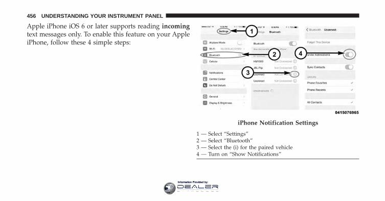
Apple iPhone iOS 6 or later supports reading incomingtext messages only. To enable this feature on your AppleiPhone, follow these 4 simple steps:
iPhone Notification Settings
1 — Select “Settings”2 — Select “Bluetooth”3 — Select the (i) for the paired vehicle4 — Turn on “Show Notifications”
456 UNDERSTANDING YOUR INSTRUMENT PANEL
Information Provided by:
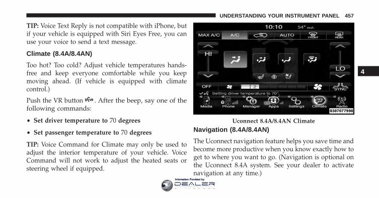
TIP: Voice Text Reply is not compatible with iPhone, butif your vehicle is equipped with Siri Eyes Free, you canuse your voice to send a text message.
Climate (8.4A/8.4AN)
Too hot? Too cold? Adjust vehicle temperatures hands-free and keep everyone comfortable while you keepmoving ahead. (If vehicle is equipped with climatecontrol.)
Push the VR button . After the beep, say one of thefollowing commands:
• Set driver temperature to 70 degrees
• Set passenger temperature to 70 degrees
TIP: Voice Command for Climate may only be used toadjust the interior temperature of your vehicle. VoiceCommand will not work to adjust the heated seats orsteering wheel if equipped.
Navigation (8.4A/8.4AN)
The Uconnect navigation feature helps you save time andbecome more productive when you know exactly how toget to where you want to go. (Navigation is optional onthe Uconnect 8.4A system. See your dealer to activatenavigation at any time.)
Uconnect 8.4A/8.4AN Climate
4
UNDERSTANDING YOUR INSTRUMENT PANEL 457
Information Provided by:
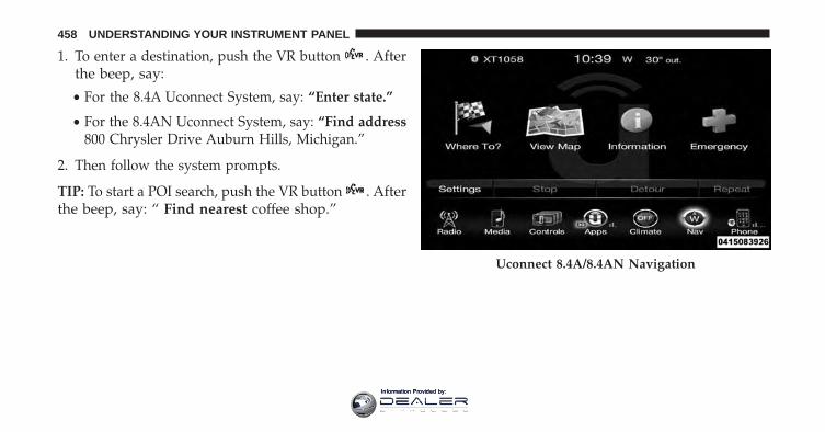
1. To enter a destination, push the VR button . Afterthe beep, say:
• For the 8.4A Uconnect System, say: “Enter state.”
• For the 8.4AN Uconnect System, say: “Find address800 Chrysler Drive Auburn Hills, Michigan.”
2. Then follow the system prompts.
TIP: To start a POI search, push the VR button . Afterthe beep, say: “ Find nearest coffee shop.”
Uconnect 8.4A/8.4AN Navigation
458 UNDERSTANDING YOUR INSTRUMENT PANEL
Information Provided by:
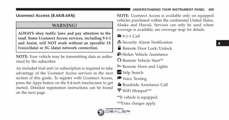
Uconnect Access (8.4A/8.4AN)
WARNING!
ALWAYS obey traffic laws and pay attention to theroad. Some Uconnect Access services, including 9-1-1and Assist, will NOT work without an operable 1X(voice/data) or 3G (data) network connection.
NOTE: Your vehicle may be transmitting data as autho-rized by the subscriber.
An included trial and/or subscription is required to takeadvantage of the Uconnect Access services in the nextsection of this guide. To register with Uconnect Access,press the Apps button on the 8.4-inch touchscreen to getstarted. Detailed registration instructions can be foundon the next page.
NOTE: Uconnect Access is available only on equippedvehicles purchased within the continental United States,Alaska and Hawaii. Services can only be used wherecoverage is available; see coverage map for details.
9-1-1 CallSecurity Alarm NotificationRemote Door Lock/UnlockStolen Vehicle AssistanceRemote Vehicle Start**Remote Horn and LightsYelp SearchVoice TextingRoadside Assistance CallWiFi Hotspot***
**If vehicle is equipped.***Extra charges apply.
4
UNDERSTANDING YOUR INSTRUMENT PANEL 459
Information Provided by:
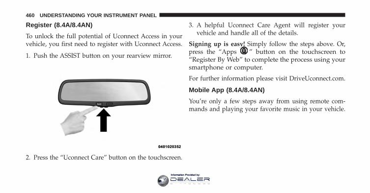
Register (8.4A/8.4AN)
To unlock the full potential of Uconnect Access in yourvehicle, you first need to register with Uconnect Access.
1. Push the ASSIST button on your rearview mirror.
2. Press the “Uconnect Care” button on the touchscreen.
3. A helpful Uconnect Care Agent will register yourvehicle and handle all of the details.
Signing up is easy! Simply follow the steps above. Or,press the “Apps ” button on the touchscreen to“Register By Web” to complete the process using yoursmartphone or computer.
For further information please visit DriveUconnect.com.
Mobile App (8.4A/8.4AN)
You’re only a few steps away from using remote com-mands and playing your favorite music in your vehicle.
460 UNDERSTANDING YOUR INSTRUMENT PANEL
Information Provided by:
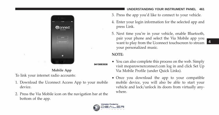
To link your internet radio accounts:
1. Download the Uconnect Access App to your mobiledevice.
2. Press the Via Mobile icon on the navigation bar at thebottom of the app.
3. Press the app you’d like to connect to your vehicle.
4. Enter your login information for the selected app andpress Link.
5. Next time you’re in your vehicle, enable Bluetooth,pair your phone and select the Via Mobile app youwant to play from the Uconnect touchscreen to streamyour personalized music.
NOTE:
• You can also complete this process on the web. Simplyvisit moparownerconnect.com log in and click Set UpVia Mobile Profile (under Quick Links).
• Once you download the app to your compatiblemobile device, you will also be able to start yourvehicle and lock/unlock its doors from virtually any-where.
Mobile App
4
UNDERSTANDING YOUR INSTRUMENT PANEL 461
Information Provided by:
Voice Texting (8.4A/8.4AN)
1. To send a message, push the Phone button . Afterthe beep, say the following command: “Send mes-sage to John Smith.”
2. Listen to the prompt. After the beep, dictate themessage you would like to send. Wait for Uconnect toprocess your message.
3. The Uconnect system will repeat your message andprovide a variety of options to add to, delete, send orhear the message again. After the beep, tell Uconnectwhat you’d like to do. For instance, if you’re happywith your message, after the beep, say: “Send.”
You must be registered with Uconnect Access and have acompatible MAP – enabled smartphone to use your voiceto send a personalized text message. For details aboutMAP, visit UconnectPhone.com.
Apple iPhone iOS6 or later supports reading incomingtext messages only. To enable this feature on your AppleiPhone, follow these 4 simple steps:
462 UNDERSTANDING YOUR INSTRUMENT PANEL
Information Provided by:
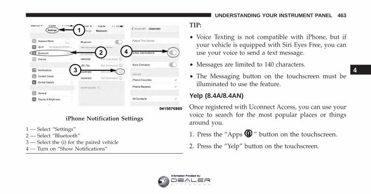
TIP:
• Voice Texting is not compatible with iPhone, but ifyour vehicle is equipped with Siri Eyes Free, you canuse your voice to send a text message.
• Messages are limited to 140 characters.
• The Messaging button on the touchscreen must beilluminated to use the feature.
Yelp (8.4A/8.4AN)
Once registered with Uconnect Access, you can use yourvoice to search for the most popular places or thingsaround you.
1. Press the “Apps ” button on the touchscreen.
2. Press the “Yelp” button on the touchscreen.
iPhone Notification Settings
1 — Select “Settings”2 — Select “Bluetooth”3 — Select the (i) for the paired vehicle4 — Turn on “Show Notifications”
4
UNDERSTANDING YOUR INSTRUMENT PANEL 463
Information Provided by:

3. Once the YELP home screen appears on the touchscreen,push the VR button , then say: “YELP search.”
4. Listen to the system prompts and after the beep, tellUconnect the place or business that you’d likeUconnect to find.
TIP: Once you perform a search, you can reorganize theresults by selecting either the Best Match, Rating orDistance tab on the top of the touchscreen display.
SiriusXM Travel Link (8.4A/8.4AN)
Need to find a gas station, view local movie listings,check a sports score or the 5 - day weather forecast?SiriusXM Travel Link is a suite of services that brings awealth of information right to your Uconnect 8.4ANsystem. (Not available for 8.4A system.)
Yelp
464 UNDERSTANDING YOUR INSTRUMENT PANEL
Information Provided by:
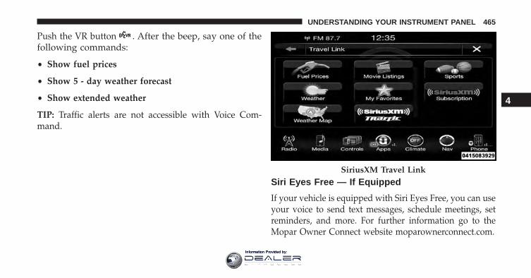
Push the VR button . After the beep, say one of thefollowing commands:
• Show fuel prices
• Show 5 - day weather forecast
• Show extended weather
TIP: Traffic alerts are not accessible with Voice Com-mand.
Siri Eyes Free — If Equipped
If your vehicle is equipped with Siri Eyes Free, you can useyour voice to send text messages, schedule meetings, setreminders, and more. For further information go to theMopar Owner Connect website moparownerconnect.com.
SiriusXM Travel Link
4
UNDERSTANDING YOUR INSTRUMENT PANEL 465
Information Provided by:
Do Not Disturb
With Do Not Disturb, you can disable notifications fromincoming calls and texts, allowing you to keep your eyeson the road and hands on the wheel. For your conve-nience there is a counter display to keep track of yourmissed calls and text messages while you were using DoNot Disturb.
Do Not Disturb can automatically reply with a textmessage, a call or both, when declining an incoming calland send it to voicemail.
Automatic reply messages can be:
• “I am driving right now, I will get back to you shortly.”
• Create a custom auto reply message up to 160 charac-ters.
NOTE: Only the first 25 characters can been seen on thetouchscreen while typing a custom message.
While in Do Not Disturb, Conference Call can be selectedso you can still place a second call without being inter-rupted by incoming calls.
NOTE:
• Reply with text message is not compatible with iP-hones.
• Auto reply with text message is only available onphones that supporting Bluetooth MAP.
General Information
This device complies with FCC rules Part 15 and IndustryCanada RSS-210. Operation is subject to the followingtwo conditions:
1. This device may not cause harmful interference.
2. This device must accept any interference that may bereceived including interference that may cause unde-sired operation.
466 UNDERSTANDING YOUR INSTRUMENT PANEL
Information Provided by:
NOTE:
• The transmitter has been tested and it complies withFCC and IC rules. Changes or modifications not ex-pressly approved by the party responsible for compli-ance could void the user’s authority to operate thedevice.
• The term IC before the certification/registration num-ber only signifies that Industry Canada technical speci-fications were met.
Additional Information
© 2015 FCA US LLC. All rights reserved. Mopar andUconnect are registered trademarks and Mopar OwnerConnect is a trademark of FCA US LLC. Android is atrademark of Google Inc. SiriusXM and all related marksand logos are trademarks of SiriusXM Radio Inc. Yelp,Yelp logo, Yelp burst and related marks are registeredtrademarks of Yelp.
Uconnect System Support:
• U.S. residents call 1-877-855-8400 (24 hours a day 7days a week) or visit DriveUconnect.com
• Canadian residents call 1-800-465-2001 (English) or1-800-387-9983 (French) or visit DriveUconnect.ca
Mon. – Fri., 8:00 am – 8:00 pm, ET
Sat., 9:00 am – 5:00 pm, ET
Sun., Closed
Uconnect Access Services Support 1-855-792-4241 Pleasehave your Uconnect Security PIN ready when you call.
4
UNDERSTANDING YOUR INSTRUMENT PANEL 467
Information Provided by:

Information Provided by:
STARTING AND OPERATING
CONTENTS� STARTING PROCEDURES . . . . . . . . . . . . . . . .474
▫ Normal Starting. . . . . . . . . . . . . . . . . . . . . . .475
▫ Extreme Cold Weather (Below –22°FOr −30°C) . . . . . . . . . . . . . . . . . . . . . . . . . .475
▫ Extended Park Starting. . . . . . . . . . . . . . . . . .475
▫ If Engine Fails To Start . . . . . . . . . . . . . . . . .476
▫ After Starting . . . . . . . . . . . . . . . . . . . . . . . .477
� STOP/START SYSTEM — IF EQUIPPED . . . . . .477
▫ Automatic Mode . . . . . . . . . . . . . . . . . . . . . .477
▫ Possible Reasons The Engine Does NotAutostop . . . . . . . . . . . . . . . . . . . . . . . . . . .478
▫ To Start The Engine While In AutostopMode . . . . . . . . . . . . . . . . . . . . . . . . . . . . . .479
▫ To Manually Turn Off The Stop/StartSystem . . . . . . . . . . . . . . . . . . . . . . . . . . . .481
▫ To Manually Turn On The Stop/Start System . .481
▫ System Malfunction . . . . . . . . . . . . . . . . . . . .481
� ENGINE BLOCK HEATER — IF EQUIPPED . . .482
� AUTOMATIC TRANSMISSION . . . . . . . . . . . .483
▫ Key Ignition Park Interlock. . . . . . . . . . . . . . .484
5
Information Provided by:
▫ Brake/Transmission Shift Interlock System . . .485
▫ Nine-Speed Automatic Transmission . . . . . . . .485
▫ Gear Ranges . . . . . . . . . . . . . . . . . . . . . . . . .487
� FOUR-WHEEL DRIVE OPERATION . . . . . . . . .494
▫ 1-Speed Four-Wheel Drive (4X4) — IfEquipped . . . . . . . . . . . . . . . . . . . . . . . . . . .494
▫ 2-Speed Four-Wheel Drive (4X4) — IfEquipped . . . . . . . . . . . . . . . . . . . . . . . . . . .496
▫ Shift Positions . . . . . . . . . . . . . . . . . . . . . . . .497
▫ Shifting Procedures . . . . . . . . . . . . . . . . . . . .498
▫ Rear Electronic Locker (E-Locker) System — IfEquipped . . . . . . . . . . . . . . . . . . . . . . . . . . .502
� SELEC-TERRAIN . . . . . . . . . . . . . . . . . . . . . .504
▫ Description . . . . . . . . . . . . . . . . . . . . . . . . . .504
� ON-ROAD DRIVING TIPS . . . . . . . . . . . . . . . .506
� OFF-ROAD DRIVING TIPS . . . . . . . . . . . . . . . .506
▫ When To Use 4WD LOW Range . . . . . . . . . . .506
▫ Driving Through Water . . . . . . . . . . . . . . . . .507
▫ Driving In Snow, Mud And Sand . . . . . . . . . .508
▫ Hill Climbing . . . . . . . . . . . . . . . . . . . . . . . .508
▫ Traction Downhill . . . . . . . . . . . . . . . . . . . . .509
▫ After Driving Off-Road . . . . . . . . . . . . . . . . .509
� POWER STEERING . . . . . . . . . . . . . . . . . . . . .510
� ELECTRIC PARK BRAKE (EPB) . . . . . . . . . . . .512
▫ Auto Park Brake . . . . . . . . . . . . . . . . . . . . . .516
▫ SafeHold . . . . . . . . . . . . . . . . . . . . . . . . . . .517
▫ Brake Service Mode . . . . . . . . . . . . . . . . . . . .517
470 STARTING AND OPERATING
Information Provided by:
� BRAKE SYSTEM . . . . . . . . . . . . . . . . . . . . . . .519
� ELECTRONIC BRAKE CONTROL SYSTEM . . . .520
▫ Electronic Brake Force Distribution (EBD) . . . .520
▫ Brake System Warning Light. . . . . . . . . . . . . .520
▫ Anti-Lock Brake System (ABS) . . . . . . . . . . . .520
▫ Anti-Lock Brake Warning Light. . . . . . . . . . . .522
▫ Brake Assist System (BAS) . . . . . . . . . . . . . . .522
▫ Hill Start Assist (HSA) . . . . . . . . . . . . . . . . .523
▫ Traction Control System (TCS) . . . . . . . . . . . .526
▫ Electronic Stability Control (ESC) . . . . . . . . . .527
▫ Electronic Roll Mitigation (ERM) . . . . . . . . . .532
▫ Trailer Sway Control (TSC) . . . . . . . . . . . . . .532
▫ Ready Alert Braking (RAB). . . . . . . . . . . . . . .533
▫ Rainy Brake Support (RBS) . . . . . . . . . . . . . . .533
▫ Dynamic Steering Torque (DST) . . . . . . . . . . .533
▫ Hill Descent Control (HDC) — If Equipped . . .534
▫ Selec Speed Control (SSC) — If Equipped . . . .537
� TIRE SAFETY INFORMATION . . . . . . . . . . . . .541
▫ Tire Markings . . . . . . . . . . . . . . . . . . . . . . . .541
▫ Tire Identification Number (TIN). . . . . . . . . . .544
▫ Tire Terminology And Definitions . . . . . . . . . .546
▫ Tire Loading And Tire Pressure . . . . . . . . . . .547
� TIRES — GENERAL INFORMATION . . . . . . . .552
▫ Tire Pressure . . . . . . . . . . . . . . . . . . . . . . . .552
▫ Tire Inflation Pressures . . . . . . . . . . . . . . . . .553
▫ Tire Pressures For High Speed Operation . . . .555
5
STARTING AND OPERATING 471
Information Provided by:
▫ Radial Ply Tires . . . . . . . . . . . . . . . . . . . . . .555
▫ Tire Types . . . . . . . . . . . . . . . . . . . . . . . . . . .556
▫ Run Flat Tires — If Equipped . . . . . . . . . . . . .558
▫ Spare Tires — If Equipped . . . . . . . . . . . . . . .558
▫ Tire Spinning . . . . . . . . . . . . . . . . . . . . . . . .561
▫ Tread Wear Indicators . . . . . . . . . . . . . . . . . .561
▫ Life Of Tire . . . . . . . . . . . . . . . . . . . . . . . . .562
▫ Replacement Tires . . . . . . . . . . . . . . . . . . . . .563
� TIRE CHAINS (TRACTION DEVICES) . . . . . . .564
� TIRE ROTATION RECOMMENDATIONS . . . . .567
� TIRE PRESSURE MONITOR SYSTEM (TPMS) . .569
▫ Premium System — If Equipped . . . . . . . . . . .572
▫ General Information. . . . . . . . . . . . . . . . . . . .576
� FUEL REQUIREMENTS . . . . . . . . . . . . . . . . . .577
▫ Reformulated Gasoline . . . . . . . . . . . . . . . . .577
▫ Gasoline/Oxygenate Blends . . . . . . . . . . . . . .578
▫ E-85 Usage In Non-Flex Fuel Vehicles . . . . . . .578
▫ MMT In Gasoline . . . . . . . . . . . . . . . . . . . . .579
▫ Materials Added To Fuel . . . . . . . . . . . . . . . .579
▫ Fuel System Cautions. . . . . . . . . . . . . . . . . . .580
▫ Carbon Monoxide Warnings . . . . . . . . . . . . .581
� FLEXIBLE FUEL (2.4L ENGINE ONLY) — IFEQUIPPED . . . . . . . . . . . . . . . . . . . . . . . . . . .581
▫ E-85 General Information . . . . . . . . . . . . . . .581
▫ Ethanol Fuel (E-85) . . . . . . . . . . . . . . . . . . . .582
▫ Fuel Requirements . . . . . . . . . . . . . . . . . . . .582
472 STARTING AND OPERATING
Information Provided by:
▫ Selection Of Engine Oil For Flexible FuelVehicles (E-85) And Gasoline Vehicles . . . . . . .583
▫ Starting . . . . . . . . . . . . . . . . . . . . . . . . . . . .583
▫ Cruising Range . . . . . . . . . . . . . . . . . . . . . . .584
▫ Replacement Parts . . . . . . . . . . . . . . . . . . . .584
▫ Maintenance . . . . . . . . . . . . . . . . . . . . . . . .584
� ADDING FUEL . . . . . . . . . . . . . . . . . . . . . . . .584
▫ Emergency Fuel Filler Door Release. . . . . . . . .587
▫ Loose Fuel Filler Cap Message . . . . . . . . . . . .588
� VEHICLE LOADING . . . . . . . . . . . . . . . . . . . .588
▫ Certification Label . . . . . . . . . . . . . . . . . . . .588
� TRAILER TOWING . . . . . . . . . . . . . . . . . . . . .591
▫ Common Towing Definitions . . . . . . . . . . . . .591
▫ Trailer Hitch Classification . . . . . . . . . . . . . . .594
▫ Trailer Towing Weights (Maximum TrailerWeight Ratings) . . . . . . . . . . . . . . . . . . . . . . .595
▫ Trailer And Tongue Weight . . . . . . . . . . . . . .596
▫ Towing Requirements . . . . . . . . . . . . . . . . . .597
▫ Towing Tips . . . . . . . . . . . . . . . . . . . . . . . . .602
� RECREATIONAL TOWING (BEHINDMOTORHOME, ETC.) . . . . . . . . . . . . . . . . . . .604
▫ Towing This Vehicle Behind Another Vehicle . .604
▫ Recreational Towing — Front-Wheel Drive(FWD) Models . . . . . . . . . . . . . . . . . . . . . . .606
▫ Recreational Towing — 4X4 Models With 1-SpeedPower Transfer Unit. . . . . . . . . . . . . . . . . . . .607
▫ Recreational Towing — 4X4 Models With 2-SpeedPower Transfer Unit. . . . . . . . . . . . . . . . . . . .607
5
STARTING AND OPERATING 473
Information Provided by:
STARTING PROCEDURES
Before starting your vehicle, adjust your seat, adjust bothinside and outside mirrors, and fasten your seat belts.
WARNING!
• When leaving the vehicle, always remove the keyfob from the ignition and lock your vehicle. Ifequipped with Keyless Enter-N-Go, always makesure the keyless ignition node is in “OFF” mode,remove the Key Fob from the vehicle and lock thevehicle.
• Never leave children alone in a vehicle, or withaccess to an unlocked vehicle.
(Continued)
WARNING! (Continued)• Allowing children to be in a vehicle unattended is
dangerous for a number of reasons. A child orothers could be seriously or fatally injured. Chil-dren should be warned not to touch the parkingbrake, brake pedal or the gear selector.
• Do not leave the key fob in or near the vehicle, orin a location accessible to children, and do notleave the ignition of a vehicle equipped withKeyless Enter-N-Go in the ACC or ON/RUN mode.A child could operate power windows, other con-trols, or move the vehicle.
Start the engine with the shift lever in the NEUTRAL orPARK position. Apply the brake before shifting to anydriving range.
474 STARTING AND OPERATING
Information Provided by:
Normal Starting
NOTE: Normal starting of either a cold or a warm engineis obtained without pumping or pressing the acceleratorpedal.
Cycle the ignition switch to the START position andrelease when the engine starts. If the engine fails to startwithin 10 seconds, cycle the ignition switch to theLOCK/OFF position, wait 10 to 15 seconds, then repeatthe “Normal Starting” procedure.
Tip Start Feature
Cycle the ignition switch to START position and release itas soon as the starter engages. The starter motor willcontinue to run, but will automatically disengage itselfwhen the engine is running. If the engine fails to start, thestarter will disengage automatically in 10 seconds. If thisoccurs, cycle the ignition switch to the OFF position, wait10 to 15 seconds, then repeat the “Normal Starting”procedure.
Extreme Cold Weather (Below –22°F Or −30°C)
To ensure reliable starting at these temperatures, use ofan externally powered electric engine block heater (avail-able from your authorized dealer) is recommended.
Extended Park Starting
NOTE: Extended Park condition occurs when the vehiclehas not been started or driven for at least 30 days.
1. Install a battery charger or jumper cables to the batteryto ensure a full battery charge during the crank cycle.
2. Cycle the ignition in the START position and release itwhen the engine starts.
3. If the engine fails to start within ten seconds, cycle theignition to the STOP (OFF/LOCK) position, wait fiveseconds to allow the starter to cool, then repeat theExtended Park Starting procedure.
5
STARTING AND OPERATING 475
Information Provided by:
4. If the engine fails to start after eight attempts, allowthe starter to cool for at least 10 minutes, then repeatthe procedure.
CAUTION!
To prevent damage to the starter, do not crank con-tinuously for more than 10 seconds at a time. Wait 10to 15 seconds before trying again.
If Engine Fails To Start
WARNING!
• Never pour fuel or other flammable liquid into thethrottle body air inlet opening in an attempt to startthe vehicle. This could result in flash fire causingserious personal injury.
(Continued)
WARNING! (Continued)• Do not attempt to push or tow your vehicle to get it
started. Vehicles equipped with an automatic trans-mission cannot be started this way. Unburned fuelcould enter the catalytic converter and once theengine has started, ignite and damage the converterand vehicle.
• If the vehicle has a discharged battery, boostercables may be used to obtain a start from a boosterbattery or the battery in another vehicle. This typeof start can be dangerous if done improperly. Referto “Jump-Starting” in “What To Do In Emergen-cies” for further information.
476 STARTING AND OPERATING
Information Provided by:
With Tip Start
If the engine fails to start after you have followed the�Normal Starting�, “Extreme Cold Weather� and �Ex-tended Park Starting� procedures, it may be flooded. Toclear any excess fuel;
1. Press the accelerator pedal all the way to the floor andhold it
2. Cycle the ignition to the START position and release itas soon as the starter engages. The starter motor willdisengage automatically in 10 seconds.
3. Once this occurs, release the accelerator pedal.
4. Cycle the ignition to the LOCK position, wait 10 to 15seconds, then repeat the “Normal Starting” procedure.
CAUTION!
To prevent damage to the starter, wait 10 to 15seconds before trying again.
After Starting
The idle speed is controlled automatically and it willdecrease as the engine warms up.
STOP/START SYSTEM — IF EQUIPPED
The Stop/Start function is developed to reduce fuelconsumption. The system will stop the engine automati-cally during a vehicle stop if the required conditions aremet. Releasing the brake pedal or pressing the acceleratorpedal will automatically re-start the engine.
Automatic Mode
The Stop/Start feature is enabled after every normalcustomer engine start. At that time, the system will go
5
STARTING AND OPERATING 477
Information Provided by:
into STOP/START READY and if all other conditions aremet, can go into a STOP/START AUTOSTOP ACTIVE“Autostop” mode.
To Activate The Autostop Mode, The Following MustOccur:
• The system must be in STOP/START READY state. ASTOP/START READY message will be displayed inthe Electronic Vehicle Information Center (EVIC) orDriver Information Display (DID) within the Stop/Start section. Refer to “Electronic Vehicle InformationCenter (EVIC)” or “Driver Information Display (DID)”in “Understanding Your Instrument Panel” for furtherinformation.
• The vehicle must be completely stopped.
• The shifter must be in a forward gear and the brakepedal depressed.
The engine will shut down, the tachometer will move tothe zero position and the Stop/Start telltale will illumi-nate indicating you are in Autostop. Customer settingswill be maintained upon return to an engine runningcondition.
Possible Reasons The Engine Does Not Autostop
Prior to engine shut down, the system will check manysafety and comfort conditions to see if they are fulfilled.Detailed information about the operation of the Stop/Start system may be viewed in the EVIC/DID Stop/StartScreen. In the following situations the engine will notstop:
• Driver’s seat belt is not buckled.
• Driver’s door is not closed.
• Battery temperature is too warm or cold.
• Battery charge is low.
478 STARTING AND OPERATING
Information Provided by:
• The vehicle is on a steep grade.
• Cabin heating or cooling is in process and an accept-able cabin temperature has not been achieved.
• HVAC is set to full defrost mode at a high blowerspeed.
• HVAC set to MAX A/C.
• Engine has not reached normal operating temperature.
• The transmission is not in a forward gear.
• Hood is open.
• Vehicle is in 4LO transfer case mode.
• Brake pedal is not pressed with sufficient pressure.
Other Factors Which Can Inhibit Autostop Include:
• Fuel level.
• Accelerator pedal input.
• Engine temp too high.
• 5 MPH threshold not achieved from previous AU-TOSTOP.
• Steering angle beyond threshold.
• ACC is on and speed is set.
It may be possible for the vehicle to be driven severaltimes without the STOP/START system going into aSTOP/START READY state under more extreme condi-tions of the items listed above.
To Start The Engine While In Autostop Mode
While in a forward gear, the engine will start when thebrake pedal is released or the throttle pedal is depressed.The transmission will automatically re-engage upon en-gine restart.
5
STARTING AND OPERATING 479
Information Provided by:
Conditions That Will Cause The Engine To Start Auto-matically While In Autostop Mode:
• The transmission selector is moved out of DRIVE.
• To maintain cabin temperature comfort.
• HVAC is set to full defrost mode.
• HVAC system temperature or fan speed is manuallyadjusted.
• Battery voltage drops too low.
• Low brake vacuum (e.g. after several brake pedalapplications).
• STOP/START OFF switch is pressed.
• A STOP/START system error occurs.
• 4WD system is put into 4LO mode.
Conditions That Force An Application Of The ElectricPark Brake While In Autostop Mode:
• The drivers door is open and brake pedal released.
• The drivers door is open and the drivers seat belt isunbuckled.
• The engine hood has been opened.
• A STOP/START system error occurs.
If the Electric Park Brake is applied with the engine off,the engine may require a manual restart and the electricpark brake may require a manual release (depress brakepedal and press Electric Park Brake switch). Refer to“Electronic Vehicle Information Center (EVIC)” or“Driver Information Display (DID)” in “UnderstandingYour Instrument Panel” for further information.
480 STARTING AND OPERATING
Information Provided by:
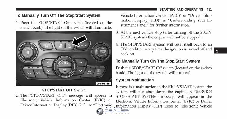
To Manually Turn Off The Stop/Start System
1. Push the STOP/START Off switch (located on theswitch bank). The light on the switch will illuminate.
2. The “STOP/START OFF” message will appear inElectronic Vehicle Information Center (EVIC) orDriver Information Display (DID). Refer to “Electronic
Vehicle Information Center (EVIC)” or “Driver Infor-mation Display (DID)” in “Understanding Your In-strument Panel” for further information.
3. At the next vehicle stop (after turning off the STOP/START system) the engine will not be stopped.
4. The STOP/START system will reset itself back to anON condition every time the ignition is turned off andback on.
To Manually Turn On The Stop/Start System
Push the STOP/START Off switch (located on the switchbank). The light on the switch will turn off.
System Malfunction
If there is a malfunction in the STOP/START system, thesystem will not shut down the engine. A “SERVICESTOP/START SYSTEM” message will appear in theElectronic Vehicle Information Center (EVIC) or DriverInformation Display (DID). Refer to “Electronic Vehicle
STOP/START OFF Switch
5
STARTING AND OPERATING 481
Information Provided by:
Information Center (EVIC)” or “Driver Information Dis-play (DID)“ in “Understanding Your Instrument Panel”for further information.
If the “SERVICE STOP/START SYSTEM” message ap-pears in the EVIC/DID, have the system checked by yourauthorized dealer.
ENGINE BLOCK HEATER — IF EQUIPPED
The engine block heater warms the engine and permitsquicker starts in cold weather.
Connect the cord to a 110-115 Volt AC electrical outletwith a grounded, three-wire extension cord.
For ambient temperatures below 0°F (-18°C), the engineblock heater is recommended. For ambient temperaturesbelow -20°F (-29°C), the engine block heater is required.
The engine block heater cord is routed under the hood,behind to the driver’s side headlamp. Follow the stepsbelow to properly use the engine block heater:
1. Locate the engine block heater cord (behind the driv-er’s side headlamp).
2. Undo the Velcro strap that secures the heater cord inplace.
3. Pull the cord to the front of the vehicle and plug it intoa grounded, three-wire extension cord.
4. After the vehicle is running, reattach the cord to theVelcro strap and properly stow away behind thedriver’s side headlamp.
NOTE:
• The engine block heater cord is a factory installedoption. If your vehicle is not equipped, heater cordsare available from your authorized MOPAR dealer.
482 STARTING AND OPERATING
Information Provided by:

• The engine block heater will require 110 Volts AC and6.5 Amps to activate the heater element.
• The engine block heater must be plugged in at leastone hour to have an adequate warming effect on theengine.
WARNING!
Remember to disconnect the engine block heatercord before driving. Damage to the 110-115 Voltelectrical cord could cause electrocution.
AUTOMATIC TRANSMISSION
WARNING!
• It is dangerous to shift out of PARK or NEUTRALif the engine speed is higher than idle speed. If
(Continued)
WARNING! (Continued)your foot is not firmly pressing the brake pedal, thevehicle could accelerate quickly forward or in re-verse. You could lose control of the vehicle and hitsomeone or something. Only shift into gear whenthe engine is idling normally and your foot isfirmly pressing the brake pedal.
• Unintended movement of a vehicle could injurethose in or near the vehicle. As with all vehicles, youshould never exit a vehicle while the engine isrunning. Before exiting a vehicle, always apply theparking brake, shift the transmission into PARK,turn the engine OFF, and remove the Key Fob. Whenthe ignition is in the LOCK/OFF (key removal)position/mode, the transmission is locked in PARK,securing the vehicle against unwanted movement.
(Continued)
5
STARTING AND OPERATING 483
Information Provided by:
WARNING! (Continued)• When leaving the vehicle, always make sure the
ignition is in the OFF position/mode, remove theKey Fob from the vehicle, and lock the vehicle.
• Never leave children alone in a vehicle, or withaccess to an unlocked vehicle. Allowing children tobe in a vehicle unattended is dangerous for anumber of reasons. A child or others could beseriously or fatally injured. Children should bewarned not to touch the parking brake, brake pedalor the transmission gear selector.
• Do not leave the Key Fob in or near the vehicle (orin a location accessible to children), and do notleave the ignition (in a vehicle equipped withKeyless Enter-N-Go) in the ACC or ON/RUNposition/mode. A child could operate power win-dows, other controls, or move the vehicle.
CAUTION!
Damage to the transmission may occur if the follow-ing precautions are not observed:• Shift into or out of PARK or REVERSE only after
the vehicle has come to a complete stop.• Do not shift between PARK, REVERSE, NEU-
TRAL, or DRIVE when the engine is above idlespeed.
• Before shifting into any gear, make sure your footis firmly pressing the brake pedal.
NOTE: You must press and hold the brake pedal whileshifting out of PARK.
Key Ignition Park Interlock
This vehicle is equipped with a Key Ignition Park Inter-lock which requires the transmission to be in PARKbefore the ignition switch can be turned to the LOCK/OFF (key removal) position. The Key Fob can only be
484 STARTING AND OPERATING
Information Provided by:
removed from the ignition when the ignition is in theLOCK/OFF position, and the transmission is locked inPARK whenever the ignition switch is in the LOCK/OFFposition.
Brake/Transmission Shift Interlock System
This vehicle is equipped with a Brake Transmission ShiftInterlock system (BTSI) that holds the shift lever in PARKunless the brakes are applied. To shift the transmissionout of PARK, the ignition must be turned to the ON/RUN position (engine running or not) and the brakepedal must be pressed.
The brake pedal must also be pressed to shift fromNEUTRAL into DRIVE or REVERSE when the vehicle isstopped or moving at low speeds.
Nine-Speed Automatic Transmission
The transmission gear range (PRND) is displayed bothbeside the shift lever and in the Electronic Vehicle Infor-mation Center (EVIC)/Driver Information Display(DID). To select a gear range, press the lock button on theshift lever and move the lever rearward or forward. Youmust also press the brake pedal to shift the transmissionout of PARK, or to shift from NEUTRAL into DRIVE orREVERSE when the vehicle is stopped or moving at lowspeeds (refer to �Brake/Transmission Shift Interlock Sys-tem� in this section). Select the DRIVE range for normaldriving.
The electronically-controlled transmission provides aprecise shift schedule. The transmission electronics areself-calibrating; therefore, the first few shifts on a newvehicle may be somewhat abrupt. This is a normalcondition, and precision shifts will develop within a fewhundred miles (kilometers).
5
STARTING AND OPERATING 485
Information Provided by:
The nine-speed transmission has been developed to meetthe needs of FCA current and future lineup of FWD/AWD vehicles. Software and calibration is refined tooptimize the customer’s driving experience and fueleconomy. By design, some vehicle and driveline combi-nations utilize 9th gear only in very specific drivingsituations and conditions.
Only shift from DRIVE to PARK or REVERSE when theaccelerator pedal is released and the vehicle is stopped.Be sure to keep your foot on the brake pedal whenshifting between these gears.
The transmission shift lever has PARK, REVERSE, NEU-TRAL, DRIVE, and Electronic Range Select (ERS) shiftpositions. Manual downshifts can be made using the ERSshift control (refer to �Electronic Range Select (ERS)Operation� in this section for further information). Mov-ing the shift lever into the ERS (-/+) position (beside the
DRIVE position) activates ERS mode, displays the cur-rent gear in the instrument cluster, and prevents auto-matic upshifts beyond this gear. In ERS mode, togglingthe shift lever forward (-) or rearward (+) will change thehighest available gear.
NOTE: If the shift lever cannot be moved to the PARK,REVERSE, or NEUTRAL position (when pushed for-ward) it is probably in the ERS (+/-) position (beside theDRIVE position). In ERS mode, the transmission gearlimit (1, 2, 3, etc.) is displayed in the instrument cluster.Move the shift lever to the right (into the DRIVE [D]position) for access to PARK, REVERSE, and NEUTRAL.
486 STARTING AND OPERATING
Information Provided by:
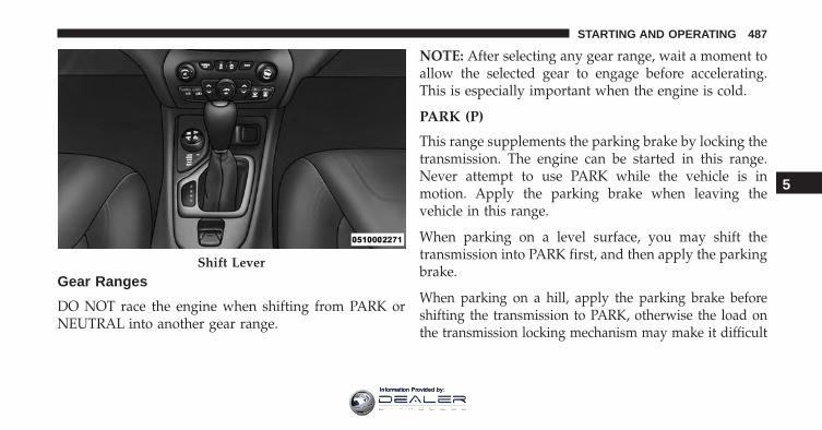
Gear Ranges
DO NOT race the engine when shifting from PARK orNEUTRAL into another gear range.
NOTE: After selecting any gear range, wait a moment toallow the selected gear to engage before accelerating.This is especially important when the engine is cold.
PARK (P)
This range supplements the parking brake by locking thetransmission. The engine can be started in this range.Never attempt to use PARK while the vehicle is inmotion. Apply the parking brake when leaving thevehicle in this range.
When parking on a level surface, you may shift thetransmission into PARK first, and then apply the parkingbrake.
When parking on a hill, apply the parking brake beforeshifting the transmission to PARK, otherwise the load onthe transmission locking mechanism may make it difficult
Shift Lever
5
STARTING AND OPERATING 487
Information Provided by:
to move the shift lever out of PARK. As an added precau-tion, turn the front wheels toward the curb on a downhillgrade and away from the curb on an uphill grade.
WARNING!
• Never use the PARK position as a substitute for theparking brake. Always apply the parking brakefully when parked to guard against vehicle move-ment and possible injury or damage.
• Your vehicle could move and injure you and othersif it is not completely in PARK. Check by trying tomove the shift lever out of PARK with the brakepedal released. Make sure the transmission is inPARK before leaving the vehicle.
• It is dangerous to shift out of PARK or NEUTRALif the engine speed is higher than idle speed. Ifyour foot is not firmly pressing the brake pedal, the
(Continued)
WARNING! (Continued)vehicle could accelerate quickly forward or in re-verse. You could lose control of the vehicle and hitsomeone or something. Only shift into gear whenthe engine is idling normally and your foot isfirmly pressing the brake pedal.
• Unintended movement of a vehicle could injurethose in or near the vehicle. As with all vehicles, youshould never exit a vehicle while the engine isrunning. Before exiting a vehicle, always apply theparking brake, shift the transmission into PARK,turn the engine OFF, and remove the Key Fob. Whenthe ignition is in the LOCK/OFF (key removal)position, the transmission is locked in PARK, secur-ing the vehicle against unwanted movement.
(Continued)
488 STARTING AND OPERATING
Information Provided by:
WARNING! (Continued)• When leaving the vehicle, always make sure the
ignition is in the OFF position, remove the key fobfrom the vehicle and lock the vehicle. If equippedwith Keyless Enter-N-Go, always make sure thekeyless ignition node is in “OFF” mode, removethe Key Fob from the vehicle and lock the vehicle.
• Never leave children alone in a vehicle, or withaccess to an unlocked vehicle. Allowing children tobe in a vehicle unattended is dangerous for anumber of reasons. A child or others could beseriously or fatally injured. Children should bewarned not to touch the parking brake, brake pedalor the shift lever.
• Do not leave the Key Fob in or near the vehicle (orin a location accessible to children), and do notleave the ignition in a vehicle equipped with
(Continued)
WARNING! (Continued)Keyless Enter-N-Go in the ACC or ON/RUN posi-tion. A child could operate power windows, othercontrols, or move the vehicle.
CAUTION!
• Before moving the shift lever out of PARK, youmust turn the ignition switch from the LOCK/OFFposition to the ON/RUN position, and also pressthe brake pedal. Otherwise, damage to the shiftlever could result.
• DO NOT race the engine when shifting fromPARK or NEUTRAL into another gear range, as thiscan damage the drivetrain.
5
STARTING AND OPERATING 489
Information Provided by:
The following indicators should be used to ensure thatyou have engaged the transmission into the PARK posi-tion:
• When shifting into PARK, press the lock button on theshift lever and firmly move the lever all the wayforward until it stops and is fully seated.
• Look at the transmission gear position display andverify that it indicates the PARK position (P).
• With brake pedal released, verify that the shift leverwill not move out of PARK.
REVERSE (R)
This range is for moving the vehicle backward. Shift intoREVERSE only after the vehicle has come to a completestop.
NEUTRAL (N)
Use this range when the vehicle is standing for prolongedperiods with the engine running. The engine may bestarted in this range. Apply the parking brake and shiftthe transmission into PARK if you must leave the vehicle.
WARNING!
Do not coast in NEUTRAL and never turn off theignition to coast down a hill. These are unsafepractices that limit your response to changing trafficor road conditions. You might lose control of thevehicle and have a collision.
490 STARTING AND OPERATING
Information Provided by:
CAUTION!
Towing the vehicle, coasting, or driving for any otherreason with the transmission in NEUTRAL can causesevere transmission damage. Refer to “RecreationalTowing” in “Starting And Operating” and “Towing ADisabled Vehicle” in “What To Do In Emergencies”for further information.
DRIVE (D)
This range should be used for most city and highwaydriving. It provides the smoothest upshifts and down-shifts, and the best fuel economy. The transmissionautomatically upshifts through all forward gears. TheDRIVE position provides optimum driving characteris-tics under all normal operating conditions.
When frequent transmission shifting occurs (such aswhen operating the vehicle under heavy loading condi-tions, in hilly terrain, traveling into strong head winds, or
while towing a heavy trailer), use the Electronic RangeSelect (ERS) shift control (refer to �Electronic Range Select(ERS) Operation� in this section for further information)to select a lower gear range. Under these conditions,using a lower gear range will improve performance andextend transmission life by reducing excessive shiftingand heat buildup.
If the transmission temperature exceeds normal operat-ing limits, the transmission controller may modify thetransmission shift schedule, reduce engine torque,and/or expand the range of torque converter clutchengagement. This is done to prevent transmission dam-age due to overheating.
If the transmission becomes extremely hot, the “Trans-mission Temperature Warning Light” may illuminate andthe transmission may operate differently until the trans-mission cools down.
5
STARTING AND OPERATING 491
Information Provided by:
During cold temperatures, transmission operation maybe modified depending on engine and transmissiontemperature as well as vehicle speed. This feature im-proves warm up time of the engine and transmission toachieve maximum efficiency. Engagement of the torqueconverter clutch, and shifts into 8th or 9th gear, areinhibited until the transmission fluid is warm (refer to the“Note” under “Torque Converter Clutch” in this section).Normal operation will resume once the transmissiontemperature has risen to a suitable level.
SPORT — If Equipped
This mode alters the transmission’s automatic shiftschedule for sportier driving. Upshift speeds are in-creased to make full use of available engine power.
SPORT mode is activated using the rotary switch on thecenter console. Refer to �Selec-Terrain� in this section forfurther information.
Transmission Limp Home Mode
Transmission function is monitored electronically forabnormal conditions. If a condition is detected that couldresult in transmission damage, Transmission Limp HomeMode is activated. In this mode, the transmission remainsin fourth gear regardless of which forward gear isselected. PARK, REVERSE, and NEUTRAL will continueto operate. The Malfunction Indicator Light (MIL) may beilluminated. Limp Home Mode allows the vehicle to bedriven to an authorized dealer for service without dam-aging the transmission.
In the event of a momentary problem, the transmissioncan be reset to regain all forward gears by performing thefollowing steps:
1. Stop the vehicle.
2. Shift the transmission into PARK.
3. Turn the ignition switch to the OFF position.
492 STARTING AND OPERATING
Information Provided by:
4. Wait approximately 10 seconds.
5. Restart the engine.
6. Shift into the desired gear range. If the problem is nolonger detected, the transmission will return to normaloperation.
NOTE: Even if the transmission can be reset, we recom-mend that you visit your authorized dealer at yourearliest possible convenience. Your authorized dealer hasdiagnostic equipment to determine if the problem couldrecur. If the transmission cannot be reset, authorizeddealer service is required.
Electronic Range Select (ERS) Operation
The Electronic Range Select (ERS) shift control allows thedriver to limit the highest available gear. For example, ifyou set the transmission gear limit to 5 (fifth gear), thetransmission will not shift above fifth gear, but will shiftthrough the lower gears normally.
You can switch between DRIVE and ERS mode at anyvehicle speed. When the shift lever is in the DRIVEposition, the transmission will operate automatically,shifting between all available gears.
Moving the shift lever to the ERS position (beside DRIVE)will activate ERS mode, display the current gear in theinstrument cluster, and set that gear as the top availablegear. Once in ERS mode, moving the shift lever forward (-)or rearward (+) will change the top available gear.
To exit ERS mode, simply return the shift lever to theDRIVE position.
WARNING!
Do not downshift for additional engine braking on aslippery surface. The drive wheels could lose theirgrip and the vehicle could skid, causing a collision orpersonal injury.
5
STARTING AND OPERATING 493
Information Provided by:
NOTE: To select the proper gear position for maximumdeceleration (engine braking), move the shift lever intothe ERS position, then simply press and hold it forward(-). The transmission will shift to the range from whichthe vehicle can best be slowed down.
Torque Converter Clutch
A feature designed to improve fuel economy has beenincluded in the automatic transmission on your vehicle.A clutch within the torque converter engages automati-cally at calibrated speeds. This may result in a slightlydifferent feeling or response during normal operation inthe upper gears. When the vehicle speed drops or duringsome accelerations, the clutch automatically disengages.
NOTE: The torque converter clutch will not engage untilthe transmission fluid is warm (usually after 1 to 3 miles[2 to 5 km] of driving). Because the engine speed is higherwhen the torque converter clutch is not engaged, it mayseem as if the transmission is not shifting properly whencold. This is normal. The torque converter clutch willfunction normally once the transmission is sufficientlywarm.
FOUR-WHEEL DRIVE OPERATION
1-Speed Four-Wheel Drive (4X4) — If Equipped
This feature provides on-demand four-wheel drive (4X4).The system is automatic with no driver inputs or addi-tional driving skills required. Under normal drivingconditions, the front wheels provide most of the traction.If the front wheels begin to lose traction, power is shiftedautomatically to the rear wheels. The greater the frontwheel traction loss, the greater the power transfer to therear wheels.
494 STARTING AND OPERATING
Information Provided by:
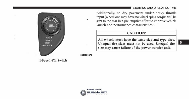
Additionally, on dry pavement under heavy throttleinput (where one may have no wheel spin), torque will besent to the rear in a pre-emptive effort to improve vehiclelaunch and performance characteristics.
CAUTION!
All wheels must have the same size and type tires.Unequal tire sizes must not be used. Unequal tiresize may cause failure of the power transfer unit.
1-Speed 4X4 Switch
5
STARTING AND OPERATING 495
Information Provided by:
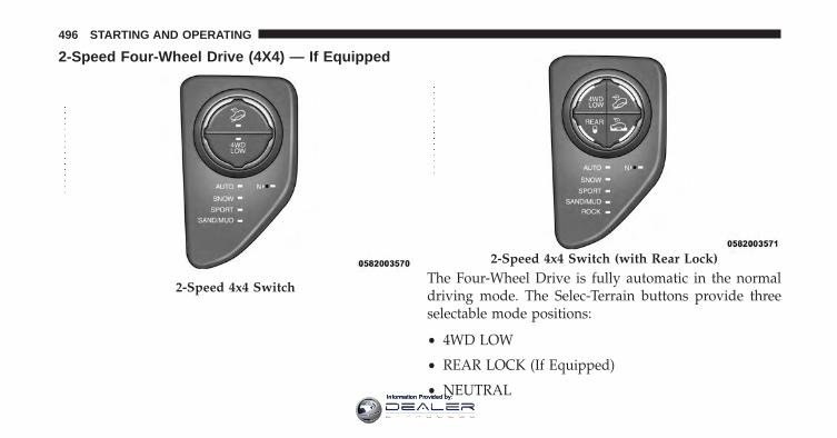
2-Speed Four-Wheel Drive (4X4) — If Equipped
The Four-Wheel Drive is fully automatic in the normaldriving mode. The Selec-Terrain buttons provide threeselectable mode positions:
• 4WD LOW
• REAR LOCK (If Equipped)
• NEUTRAL
2-Speed 4x4 Switch
2-Speed 4x4 Switch (with Rear Lock)
496 STARTING AND OPERATING
Information Provided by:
When additional traction is required, the 4WD LOWrange position can be used to provide an additional gearreduction which allows for increased torque to be deliv-ered to both the front and rear wheels. 4WD LOW isintended for loose, slippery road surfaces only. Driving in4WD LOW on dry, hard-surfaced roads may cause in-creased tire wear and damage to driveline components.
When operating your vehicle in 4WD LOW, the enginespeed is approximately three times that of the normaldriving mode at a given road speed. Take care not tooverspeed the engine and do not exceed 25 mph(40 km/h).
Proper operation of four-wheel drive vehicles dependson tires of equal size, type, and circumference on eachwheel. Any difference will adversely affect shifting andcause damage to the driveline components.
Because four-wheel drive provides improved traction,there is a tendency to exceed safe turning and stoppingspeeds. Do not go faster than road conditions permit.
Shift Positions
For additional information on the appropriate use of each4WD system mode position, see the information below:
NEUTRAL
This range disengages the driveline from the powertrain.It is to be used for flat towing behind another vehicle.Refer to “Recreational Towing” in “Starting And Operat-ing” for further information.
5
STARTING AND OPERATING 497
Information Provided by:
WARNING!
You or others could be injured or killed if you leavethe vehicle unattended with the power transfer unitin the NEUTRAL (N) position without first fullyengaging the parking brake. The NEUTRAL (N)position disengages both the front and rear drive-shafts from the powertrain and will allow the vehicleto roll, even if the automatic transmission is in PARK(or manual transmission is in gear). The parkingbrake should always be applied when the driver isnot in the vehicle.
4WD LOW
This range is for low speed four-wheel drive. It providesan additional gear reduction which allows for increasedtorque to be delivered to both the front and rear wheels
while providing maximum pulling power for loose,slippery road surfaces only. Do not exceed 25 mph(40 km/h).
NOTE: Refer to “Selec-Terrain – If Equipped” for furtherinformation on the various positions and their intendedusages.
Shifting Procedures
Shifting Into 4X4 LOW
With the vehicle at speeds of 0 to 3 mph (0 to 5 km/h), theignition switch in the ON position and the engine run-ning, shift the transmission into NEUTRAL, and push the“4WD LOW” button once. The “4WD LOW” indicatorlight in the instrument cluster will begin to flash andremain on solid when the shift is complete.
498 STARTING AND OPERATING
Information Provided by:
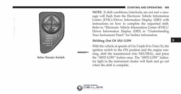
NOTE: If shift conditions/interlocks are not met a mes-sage will flash from the Electronic Vehicle InformationCenter (EVIC)/Driver Information Display (DID) withinstructions on how to complete the requested shift.Refer to “Electronic Vehicle Information Center (EVIC)/Driver Information Display (DID) in “UnderstandingYour Instrument Panel” for further information.
Shifting Out Of 4X4 LOW
With the vehicle at speeds of 0 to 3 mph (0 to 5 km/h), theignition switch in the ON position and the engine run-ning, shift the transmission into NEUTRAL, and pressthe “4WD LOW” button once. The “4WD LOW” indica-tor light in the instrument cluster will flash and go outwhen the shift is complete.
Selec-Terrain Switch
5
STARTING AND OPERATING 499
Information Provided by:
NOTE:
• If shift conditions/interlocks are not met, a message willflash from the Electronic Vehicle Information Center(EVIC)/Driver Information Display (DID) with instruc-tions on how to complete the requested shift. Refer to“Electronic Vehicle Information Center (EVIC)/DriverInformation Display (DID) in “Understanding Your In-strument Panel” for further information.
• Shifting into or out of 4WD LOW is possible with thevehicle completely stopped; however, difficulty mayoccur due to the mating clutch teeth not being prop-erly aligned. Several attempts may be required forclutch teeth alignment and shift completion to occur.The preferred method is with the vehicle rolling 0 to3 mph (0 to 5 km/h). If the vehicle is moving fasterthan 3 mph (5 km/h), the 4WD system will not allowthe shift.
NEUTRAL Shift Procedure
WARNING!
You or others could be injured or killed if you leavethe vehicle unattended with the power transfer unitin the NEUTRAL (N) position without first fullyengaging the parking brake. The NEUTRAL (N)position disengages both the front and rear drive-shafts from the powertrain and will allow the vehicleto roll, even if the automatic transmission is in PARK(or manual transmission is in gear). The parkingbrake should always be applied when the driver isnot in the vehicle.
1. Bring the vehicle to a complete stop and shift thetransmission to PARK.
2. Turn the engine OFF.
500 STARTING AND OPERATING
Information Provided by:
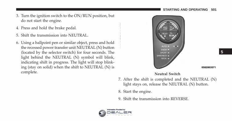
3. Turn the ignition switch to the ON/RUN position, butdo not start the engine.
4. Press and hold the brake pedal.
5. Shift the transmission into NEUTRAL.
6. Using a ballpoint pen or similar object, press and holdthe recessed power transfer unit NEUTRAL (N) button(located by the selector switch) for four seconds. Thelight behind the NEUTRAL (N) symbol will blink,indicating shift in progress. The light will stop blink-ing (stay on solid) when the shift to NEUTRAL (N) iscomplete.
7. After the shift is completed and the NEUTRAL (N)light stays on, release the NEUTRAL (N) button.
8. Start the engine.
9. Shift the transmission into REVERSE.
Neutral Switch
5
STARTING AND OPERATING 501
Information Provided by:
10. Release the brake pedal for five seconds and ensurethat there is no vehicle movement.
11. Shift the transmission to NEUTRAL.
12. Apply the parking brake.
13. Shift the transmission into PARK, turn the engineOFF, and remove the Key Fob.
Repeat steps 1-7 to shift out of NEUTRAL.
Rear Electronic Locker (E-Locker) System — IfEquipped
The Rear E-Locker System features a mechanical lockingrear differential to provide better traction in the 4WDLOW position. The “REAR LOCK” button is on theSelec-Terrain Knob.
Activating The Rear E-Locker
To activate the Rear E-Locker System, the followingconditions must be met:
1. The 4WD system must be in 4WD LOW.
2. The ignition switch in the ON position and the enginerunning.
3. Vehicle speed must be below 15 MPH (24 km/h).
4. To engage Rear E-Locker, push the REAR LOCKbutton once.
Deactivating The Rear E-Locker System
To deactivate the Rear E-Locker System, the followingconditions must be met:
1. Rear E-Locker must be engaged, and the REAR LOCKindicator light on.
502 STARTING AND OPERATING
Information Provided by:
2. The ignition switch in the ON position and the enginerunning.
3. To disengage Rear E-Locker, push the REAR LOCKbutton once.
NOTE:
• It may also be necessary to drive slowly steering backand forth to complete engagement and disengagementof the E-Locker.
• When engaging Rear E-Locker, the indicator lights inthe instrument cluster and on the REAR LOCK buttonwill begin to flash. When the shift is complete theREAR LOCK indicator lights will remain on.
• When disengaging Rear E-Locker, the indicator lightsin the instrument cluster and on the REAR LOCKbutton will begin to flash. When the shift is completethe REAR LOCK indicator lights will remain off.
• Shifting into or out of Rear E-Locker is possible withthe vehicle completely stopped; however, difficultymay occur due to the mating clutch teeth not beingproperly aligned. Several attempts may be required forclutch teeth alignment and shift completion to occur.The preferred method is for the vehicle to be rolling,below 15 MPH (24 km/h), while including right andleft steering maneuvers to allow for the clutch teeth toalign.
• The Rear E-Locker System must be disengaged prior totaking the vehicle out of 4WD LOW range. If 4WDLOW shift conditions/interlocks are not met, a mes-sage will flash from the Electronic Vehicle InformationCenter (EVIC)/Driver Information Display (DID) withinstructions on how to complete the requested shift.
5
STARTING AND OPERATING 503
Information Provided by:
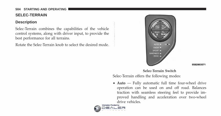
SELEC-TERRAIN
Description
Selec-Terrain combines the capabilities of the vehiclecontrol systems, along with driver input, to provide thebest performance for all terrains.
Rotate the Selec-Terrain knob to select the desired mode.
Selec-Terrain offers the following modes:
• Auto — Fully automatic full time four-wheel driveoperation can be used on and off road. Balancestraction with seamless steering feel to provide im-proved handling and acceleration over two-wheeldrive vehicles.
Selec-Terrain Switch
504 STARTING AND OPERATING
Information Provided by:
• Snow — Tuning set for additional stability in inclem-ent weather. Use on and off road on loose tractionsurfaces such as snow. When in SNOW mode (depend-ing on certain operating conditions), the transmissionmay use second gear (rather than first gear) duringlaunches, to minimize wheel slippage.
• Sport — This mode alters the transmission’s automaticshift schedule for sportier driving. Upshift speeds areincreased to make full use of available engine power.
NOTE: SPORT mode is not available when 4WD LOW isselected.
• Sand/Mud — Off road calibration for use on lowtraction surfaces such as mud, sand, or wet grass.Driveline is maximized for traction. Some binding maybe felt on less forgiving surfaces. The electronic brakecontrols are set to limit traction control management ofthrottle and wheel spin.
• Rock — Off-road calibration only available in 4WDLOW range. Traction based tuning with improvedsteer-ability for use on high traction off-road surfaces.Use for low speed obstacles such as large rocks, deepruts, etc.
NOTE:
• Rock mode is only available on the vehicles equippedwith the Off-Road package.
• Activate the Hill Descent Control or Selec SpeedControl for steep downhill control. See “ElectronicBrake Control System” in this section for furtherinformation.
5
STARTING AND OPERATING 505
Information Provided by:
Electronic Vehicle Information Center(EVIC)/Driver Information Display (DID) DisplayMessages
When the appropriate conditions exist, a message willappear in the EVIC/DID display. Refer to “ElectronicVehicle Information Center (EVIC)/Driver InformationDisplay (DID)” in “Understanding Your InstrumentPanel” for further information.
ON-ROAD DRIVING TIPS
Utility vehicles have higher ground clearance and anarrower track to make them capable of performing in awide variety of off-road applications. Specific designcharacteristics give them a higher center of gravity thanordinary cars.
An advantage of the higher ground clearance is a betterview of the road, allowing you to anticipate problems.They are not designed for cornering at the same speeds as
conventional two-wheel drive vehicles any more thanlow-slung sports cars are designed to perform satisfacto-rily in off-road conditions. If at all possible, avoid sharpturns or abrupt maneuvers. As with other vehicles of thistype, failure to operate this vehicle correctly may result inloss of control or vehicle rollover.
OFF-ROAD DRIVING TIPS
When To Use 4WD LOW Range
When off-road driving, shift to 4WD LOW for additionaltraction and control on slippery or difficult terrain,ascending or descending steep hills, and to increaselow-speed pulling power (refer to “All Wheel Drive andFour-Wheel Drive Operation” in this section for furtherdetails). This range should be limited to extreme situa-tions such as deep snow, mud, or sand where additionallow speed pulling power is needed. Vehicle speeds inexcess of 25 mph (40 km/h) should be avoided when in4WD LOW range.
506 STARTING AND OPERATING
Information Provided by:
Driving Through Water
Although your vehicle is capable of driving throughwater, there are a number of precautions that must beconsidered before entering the water:
CAUTION!
When driving through water, do not exceed 5 mph(8 km/h). Always check water depth before enteringas a precaution, and check all fluids afterward. Driv-ing through water may cause damage that may not becovered by the New Vehicle Limited Warranty.
Driving through water more than a few inches/centimeters deep will require extra caution to ensuresafety and prevent damage to your vehicle. If you mustdrive through water, try to determine the depth and thebottom condition (and location of any obstacles) prior to
entering. Proceed with caution and maintain a steadycontrolled speed less than 5 mph (8 km/h) in deep waterto minimize wave effects.
Flowing Water
If the water is swift flowing and rising (as in stormrun-off) avoid crossing until the water level recedesand/or the flow rate is reduced. If you must crossflowing-water, avoid depths in excess of 9 inches (22 cm).The flowing water can erode the streambed causing yourvehicle to sink into deeper water. Determine exit point(s)that are downstream of your entry point to allow fordrifting.
Standing Water
Avoid driving in standing water deeper than 19 inches(48 cm), and reduce speed appropriately to minimizewave effects. Maximum speed in 19 inches (48 cm) ofwater is less than 5 mph (8 km/h).
5
STARTING AND OPERATING 507
Information Provided by:
Maintenance
After driving through deep water, inspect your vehiclefluids and lubricants (engine, transmission, Power Trans-fer Unit and Rear Drive Module) to assure they have notbeen contaminated. Contaminated fluids and lubricants(milky, foamy in appearance) should be flushed/changedas soon as possible to prevent component damage.
Driving In Snow, Mud And Sand
In heavy snow, when pulling a load, or for additionalcontrol at slower speeds, shift the transmission to a lowgear and shift the 4WD system to the appropriate terrainmode, using 4WD LOW if necessary. Refer to “Four-Wheel Drive Operation” in “Starting And Operating” forfurther information. Do not shift to a lower gear thannecessary to maintain headway. Over-revving the enginecan spin the wheels and traction will be lost.
Avoid abrupt downshifts on icy or slippery roads be-cause engine braking may cause skidding and loss ofcontrol.
Hill Climbing
NOTE: Before attempting to climb a hill, determine theconditions at the crest and/or on the other side.
Before climbing a steep hill, shift the transmission to alower gear and shift the 4WD System to 4WD LOW. Usefirst gear and 4WD LOW for very steep hills.
If you stall or begin to lose headway while climbing asteep hill, allow your vehicle to come to a stop andimmediately apply the brakes. Restart the engine and shiftto REVERSE. Back slowly down the hill allowing thecompression braking of the engine to help regulate yourspeed. If the brakes are required to control vehicle speed,apply them lightly and avoid locking or skidding the tires.
508 STARTING AND OPERATING
Information Provided by:
WARNING!
If the engine stalls or you lose headway or cannotmake it to the top of a steep hill or grade, neverattempt to turn around. To do so may result intipping and rolling the vehicle. Always back straightdown a hill in REVERSE gear carefully. Never backdown a hill in NEUTRAL using only the brake.
NOTE: Remember, never drive diagonally across a hill -drive straight up or down.
If the wheels start to slip as you approach the crest of ahill, ease off the accelerator and maintain headway byturning the front wheels slowly left and right. This mayprovide a fresh “bite” into the surface and will usuallyprovide traction to complete the climb.
Traction Downhill
Shift the transmission into a low gear and the 4WDSystem to 4WD LOW range or Select Hill DescentControl if equipped (refer to �Electronic Brake ControlSystem� in this section for further information). Let thevehicle go slowly down the hill with all four wheelsturning against engine compression drag. This will per-mit you to control the vehicle speed and direction.
When descending mountains or hills, repeated brakingcan cause brake fade with loss of braking control. Avoidrepeated heavy braking by downshifting the transmis-sion whenever possible.
After Driving Off-Road
Off-road operation puts more stress on your vehicle thandoes most on-road driving. After going off-road, it isalways a good idea to check for damage. That way youcan get any problems taken care of right away and haveyour vehicle ready when you need it.
5
STARTING AND OPERATING 509
Information Provided by:
• Completely inspect the underbody of your vehicle.Check tires, body structure, steering, suspension, andexhaust system for damage.
• Inspect the radiator for mud and debris and clean asrequired.
• Check threaded fasteners for looseness, particularly onthe chassis, drivetrain components, steering, and sus-pension. Retighten them, if required, and torque to thevalues specified in the Service Manual.
• Check for accumulations of plants or brush. Thesethings could be a fire hazard. They might hide damageto fuel lines, brake hoses, axle pinion seals, andpropeller shafts.
• After extended operation in mud, sand, water, orsimilar dirty conditions, have the radiator, fan, brakerotors, wheels, brake linings, and axle yokes inspectedand cleaned as soon as possible.
WARNING!
Abrasive material in any part of the brakes may causeexcessive wear or unpredictable braking. You mightnot have full braking power when you need it toprevent a collision. If you have been operating yourvehicle in dirty conditions, get your brakes checkedand cleaned as necessary.
• If you experience unusual vibration after driving inmud, slush or similar conditions, check the wheels forimpacted material. Impacted material can cause awheel imbalance and freeing the wheels of it willcorrect the situation.
POWER STEERING
The electric power steering system will give you goodvehicle response and increased ease of maneuverabilityin tight spaces. The system will vary its assist to provide
510 STARTING AND OPERATING
Information Provided by:
light efforts while parking and good feel while driving. Ifthe electric steering system experiences a fault thatreduces assist or prevents the vehicle from providingassist, you will still have the ability to steer the vehiclemanually.
WARNING!
Continued operation with reduced assist could posea safety risk to yourself and others. Service should beobtained as soon as possible.
If the “SERVICE POWER STEERING� OR�POWER STEERING ASSIST OFF - SERVICESYSTEM” message and a steering wheel iconare displayed on the EVIC/DID screen, it indi-
cates that the vehicle needs to be taken to the dealer forservice. It is likely the vehicle has lost power steeringassistance. Refer to “Electronic Vehicle Information
(EVIC) or �Driver Information Display (DID)” in “Under-standing Your Instrument Panel” for further information.
If the “POWER STEERING SYSTEM HOT - PERFOR-MANCE MAY BE LIMITED” message and an icon aredisplayed on the EVIC/DID screen, it indicates thatextreme steering maneuvers may have occurred, whichcaused an over temperature condition in the powersteering system. You will lose power steering assistancemomentarily until the over temperature condition nolonger exists. Once driving conditions are safe, then pullover and let vehicle idle for a few moments until the lightturns off. Refer to “Electronic Vehicle Information(EVIC)/Driver Information Display (DID)” in “Under-standing Your Instrument Panel” for further information.
5
STARTING AND OPERATING 511
Information Provided by:
NOTE:
• Even if the power steering assistance is no longeroperational, it is still possible to steer the vehicle.Under these conditions there will be a substantialincrease in steering effort, especially at low speeds andduring parking maneuvers.
• If the condition persists, see your authorized dealer forservice.
ELECTRIC PARK BRAKE (EPB)
Your vehicle is equipped with an Electric Park BrakeSystem (EPB) that offers simple operation, and someadditional features that make the parking brake moreconvenient and useful.
The parking brake is primarily intended to prevent thevehicle from rolling while parked. Before leaving thevehicle, make sure that the park brake is applied. Also, becertain to leave the transmission in PARK.
You can engage the park brake in two ways;
• Manually, by applying the park brake switch.
• Automatically, by enabling the Auto Park Brake fea-ture in the customer programmable features section ofthe Uconnect settings.
The park brake switch is located in the center console.
512 STARTING AND OPERATING
Information Provided by:
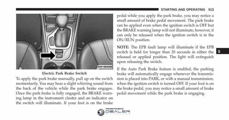
To apply the park brake manually, pull up on the switchmomentarily. You may hear a slight whirring sound fromthe back of the vehicle while the park brake engages.Once the park brake is fully engaged, the BRAKE warn-ing lamp in the instrument cluster and an indicator onthe switch will illuminate. If your foot is on the brake
pedal while you apply the park brake, you may notice asmall amount of brake pedal movement. The park brakecan be applied even when the ignition switch is OFF butthe BRAKE warning lamp will not illuminate, however, itcan only be released when the ignition switch is in theON/RUN position.
NOTE: The EPB fault lamp will illuminate if the EPBswitch is held for longer than 20 seconds in either thereleased or applied position. The light will extinguishupon releasing the switch.
If the Auto Park Brake feature is enabled, the parkingbrake will automatically engage whenever the transmis-sion is placed into PARK, or with a manual transmission,when the ignition switch is turned OFF. If your foot is onthe brake pedal, you may notice a small amount of brakepedal movement while the park brake is engaging.
Electric Park Brake Switch
5
STARTING AND OPERATING 513
Information Provided by:
The park brake will release automatically when theignition switch is ON, the transmission is in DRIVE orREVERSE, the driver seat belt is buckled, and an attemptis made to drive away.
To release the park brake manually, the ignition switchmust be in the ON/RUN position. Put your foot on thebrake pedal, then push the park brake switch downmomentarily. You may hear a slight whirring sound fromthe back of the car while the parking brake disengages.You may also notice a small amount of movement in thebrake pedal. Once the park brake is fully disengaged, TheBRAKE warning lamp in the instrument cluster and theLED indicator on the switch will extinguish.
NOTE: When parking on a hill, it is important to turn thefront wheels toward the curb on a downhill grade andaway from the curb on an uphill grade. Apply the parkbrake before placing the shift lever in PARK, otherwisethe load on the transmission locking mechanism maymake it difficult to move the shift lever out of PARK. Theparking brake should always be applied whenever thedriver is not in the vehicle.
WARNING!
• Never use the PARK position as a substitute for theparking brake. Always apply the parking brakefully when parked to guard against vehicle move-ment and possible injury or damage.
• When leaving the vehicle, always remove the KeyFob from the ignition and lock your vehicle.
(Continued)
514 STARTING AND OPERATING
Information Provided by:
WARNING! (Continued)• Never leave children alone in a vehicle, or with
access to an unlocked vehicle. Allowing children tobe in a vehicle unattended is dangerous for anumber of reasons. A child or others could beseriously or fatally injured. Children should bewarned not to touch the parking brake, brake pedalor the shift lever.
• Do not leave the Key Fob in or near the vehicle, orin a location accessible to children, and do notleave a vehicle equipped with Keyless Enter-N-Goin the ACC or ON/RUN mode. A child couldoperate power windows, other controls, or movethe vehicle.
• Be sure the parking brake is fully disengagedbefore driving; failure to do so can lead to brakefailure and a collision.
(Continued)
WARNING! (Continued)• Always fully apply the parking brake when leav-
ing your vehicle, or it may roll and cause damage orinjury. Also be certain to leave the transmission inPARK. Failure to do so may allow the vehicle to rolland cause damage or injury.
CAUTION!
If the Brake System Warning Light remains on withthe parking brake released, a brake system malfunc-tion is indicated. Have the brake system serviced byan authorized dealer immediately.
If exceptional circumstances should make it necessary toengage the park brake while the vehicle is in motion,maintain upward pressure on the electric park brakeswitch for as long as engagement is desired. The Brakewarning lamp will illuminate, and a continuous chime
5
STARTING AND OPERATING 515
Information Provided by:
will sound. The rear stop lamps will also be illuminatedautomatically while the vehicle remains in motion.
To disengage the park brake while the vehicle is inmotion, release the switch. If the vehicle is brought to acomplete stop using the parking brake, when the vehiclereaches approximately 3 mph, (5 km/h) the parkingbrake will remain engaged.
WARNING!
Driving the vehicle with the parking brake engaged,or repeated use of the parking brake to slow thevehicle may cause serious damage to the brake sys-tem; failure to do so can lead to brake failure and acollision.
In the unlikely event of a malfunction of the Electric ParkBrake system, a yellow EPB fault lamp will illuminate.This may be accompanied by the Brake warning lamp
flashing. In this event, urgent service of the electric parkbrake system is required. Do not rely on the parkingbrake to hold the vehicle stationary.
Auto Park Brake
The electric park brake can be programmed to be appliedautomatically whenever the vehicle is at a standstill andthe automatic transmission is placed in PARK, or with amanual transmission, whenever the ignition switch isturned “OFF”. Auto Park Brake is enabled and disabledby customer selection through the customer program-mable features section of the Uconnect Settings.
Any single auto park brake application can be bypassedby pressing the EPB switch to the release position whilethe transmission is placed in PARK.
516 STARTING AND OPERATING
Information Provided by:
SafeHold
SafeHold is a safety feature of the Electric Park BrakeSystem that will engage the park brake automatically ifthe vehicle is left unsecured while the ignition switch isin RUN.
For automatic transmissions, the park brake will auto-matically engage if all of the following conditions aremet:
• The vehicle is at a standstill.
• There is no attempt to depress the brake pedal oraccelerator pedal.
• The seat belt is unbuckled.
• The driver door is open.
For manual transmissions, the park brake will automati-cally engage if all of the following conditions are met:
• The vehicle is at a standstill.
• There is no attempt to depress the brake pedal oraccelerator pedal.
• The clutch pedal is not pressed.
• The seat belt is unbuckled.
• The driver door is open.
SafeHold can be temporarily bypassed by pressing theElectric Park Brake Switch while the driver door is open.Once manually bypassed, SafeHold will be enabled againonce the vehicle reaches 12 mph (20 km/h) or the ignitionis turned to the OFF position and back to ON again.
Brake Service Mode
We recommend having your brakes serviced by yourauthorized dealer. You should only make repairs forwhich you have the knowledge and the right equipment.You should only enter Brake Service Mode during brakeservice.
5
STARTING AND OPERATING 517
Information Provided by:
When servicing your rear brakes, it may be necessary foryou or your technician to push the rear piston into therear caliper bore. With the electric park brake system, thiscan only be done after retracting the Electric Park Brakeactuator. Fortunately, actuator retraction can be doneeasily by entering the Brake Service Mode through theUconnect Settings in your vehicle. This menu basedsystem will guide you through the steps necessary toretract the EPB actuator in order to perform rear brakeservice.
Service Mode has requirements that must be met in orderto be activated:
• The vehicle must be at a standstill.
• The park brake must be unapplied.
• The transmission must be in Park or Neutral.
While in service mode, the Electric Park Brake fault lampwill flash continuously while the ignition switch is ON.
When brake service work is complete, the following stepsmust be followed to reset the park brake system tonormal operation:
• Ensure the vehicle is at a standstill.
• Press the brake pedal with moderate force.
• Apply the Electric Park Brake Switch.
WARNING!
You can be badly injured working on or around amotor vehicle. Do only that service work for which youhave the knowledge and the right equipment. If youhave any doubt about your ability to perform a servicejob, take your vehicle to a competent mechanic.
518 STARTING AND OPERATING
Information Provided by:
BRAKE SYSTEM
Your vehicle is equipped with dual hydraulicbrake systems. If either of the two hydraulicsystems loses normal capability, the remainingsystem will still function. However, there will
be some loss of overall braking effectiveness. This will beevident by increased pedal travel during application andgreater pedal force required to slow or stop the vehicle. Inaddition, if the malfunction is caused by a leak in thehydraulic system, the “Brake Warning Light” will turn onas the brake fluid level drops in the master cylinder.
In the event power assist is lost for any reason (i.e.,repeated brake applications with the engine OFF) thebrakes will still function. However, the effort required tobrake the vehicle will be much greater than that requiredwith the power system operating.
WARNING!
• Riding the brakes can lead to brake failure andpossibly a collision. Driving with your foot restingor riding on the brake pedal can result in abnor-mally high brake temperatures, excessive liningwear, and possible brake damage. You would nothave your full braking capacity in an emergency.
• Driving a vehicle with the “Brake Warning Light”on is dangerous. A significant decrease in brakingperformance or vehicle stability during brakingmay occur. It will take you longer to stop thevehicle or will make your vehicle harder to control.You could have a collision. Have the vehiclechecked immediately.
5
STARTING AND OPERATING 519
Information Provided by:
ELECTRONIC BRAKE CONTROL SYSTEM
Your vehicle is equipped with an advanced ElectronicBrake Control system (EBC). This system includes Elec-tronic Brake Force Distribution (EBD), Anti-Lock BrakeSystem (ABS), Brake Assist System (BAS), Hill StartAssist (HSA), Traction Control System (TCS), ElectronicStability Control (ESC), and Electronic Roll Mitigation(ERM). These systems work together to enhance bothvehicle stability and control in various driving condi-tions.
Your vehicle may also be equipped with Trailer SwayControl (TSC), Ready Alert Braking (RAB), Rain BrakeSupport (RBS), Dynamic Steering Torque (DST), HillDescent Control (HDC), and Selec-Speed Control (SSC).
Electronic Brake Force Distribution (EBD)
This function manages the distribution of the brakingtorque between the front and rear axles by limitingbraking pressure to the rear axle. This is done to prevent
overslip of the rear wheels to avoid vehicle instability,and to prevent the rear axle from entering ABS before thefront axle.
Brake System Warning Light
The red “Brake System Warning Light” will turn on whenthe ignition switch is turned to the ON position and maystay on for as long as four seconds.
If the “Brake System Warning Light” remains on orcomes on while driving, it indicates that the brake systemis not functioning properly and that immediate service isrequired. If the “Brake System Warning Light” does notcome on when the ignition switch is turned to the ONposition, have the light repaired as soon as possible.
Anti-Lock Brake System (ABS)
The Anti-Lock Brake System (ABS) provides increasedvehicle stability and brake performance under most
520 STARTING AND OPERATING
Information Provided by:
braking conditions. The system automatically preventswheel lock, and enhances vehicle control during braking.
The ABS performs a self-check cycle to ensure that theABS is working properly each time the vehicle is startedand driven. During this self-check you may hear a slightclicking sound as well as some related motor noises.
ABS is activated during braking when the system detectsone or more wheels begins to lock. Road conditions such asice, snow, gravel, bumps, railroad tracks, loose debris, orpanic stops may increase the likelihood of ABS activation(s).
You also may experience the following when ABS activates:
• The ABS motor noise (it may continue to run for ashort time after the stop).
• The clicking sound of solenoid valves.
• Brake pedal pulsations.
• A slight drop of the brake pedal at the end of the stop.
These are all normal characteristics of ABS.
WARNING!
• The ABS contains sophisticated electronic equip-ment that may be susceptible to interferencecaused by improperly installed or high outputradio transmitting equipment. This interferencecan cause possible loss of anti-lock braking capa-bility. Installation of such equipment should beperformed by qualified professionals.
• Pumping of the Anti-Lock Brakes will diminishtheir effectiveness and may lead to a collision.Pumping makes the stopping distance longer. Justpress firmly on your brake pedal when you need toslow down or stop.
• The ABS cannot prevent the natural laws of phys-ics from acting on the vehicle, nor can it increase
(Continued)
5
STARTING AND OPERATING 521
Information Provided by:
WARNING! (Continued)braking or steering efficiency beyond that affordedby the condition of the vehicle brakes and tires orthe traction afforded.
• The ABS cannot prevent collisions, including thoseresulting from excessive speed in turns, followinganother vehicle too closely, or hydroplaning.
• The capabilities of an ABS equipped vehicle mustnever be exploited in a reckless or dangerousmanner that could jeopardize the user’s safety orthe safety of others.
ABS is designed to function with the OEM tires. Modifi-cation may result in degraded ABS performance.
Anti-Lock Brake Warning Light
The amber “Anti-Lock Brake Warning Light” will turn onwhen the ignition switch is turned to the ON positionand may stay on for as long as four seconds.
If the “Anti-Lock Brake Warning Light” remains on orcomes on while driving, it indicates that the anti-lockportion of the brake system is not functioning and thatservice is required. However, the conventional brakesystem will continue to operate normally if the “BrakeSystem Warning Light” is not on.
If the “Anti-Lock Brake Warning Light” is on, the brakesystem should be serviced as soon as possible to restorethe benefits of anti-lock brakes. If the “Anti-Lock BrakeWarning Light” does not come on when the ignitionswitch is turned to the ON position, have the lightrepaired as soon as possible.
Brake Assist System (BAS)
The BAS is designed to optimize the vehicle’s brakingcapability during emergency braking maneuvers. Thesystem detects an emergency braking situation by sens-ing the rate and amount of brake application and thenapplies optimum pressure to the brakes. This can help
522 STARTING AND OPERATING
Information Provided by:
reduce braking distances. The BAS complements theanti-lock brake system (ABS). Applying the brakes veryquickly results in the best BAS assistance. To receive thebenefit of the system, you must apply continuous brak-ing pressure during the stopping sequence, (do not“pump” the brakes). Do not reduce brake pedal pressureunless braking is no longer desired. Once the brake pedalis released, the BAS is deactivated.
WARNING!
The Brake Assist System (BAS) cannot prevent thenatural laws of physics from acting on the vehicle,nor can it increase the traction afforded by prevailingroad conditions. BAS cannot prevent collisions, in-cluding those resulting from excessive speed inturns, driving on very slippery surfaces, or hydro-planing. The capabilities of a BAS-equipped vehicle
(Continued)
WARNING! (Continued)must never be exploited in a reckless or dangerousmanner, which could jeopardize the user’s safety orthe safety of others.
Hill Start Assist (HSA)
The HSA system is designed to mitigate roll back from acomplete stop while on an incline. If the driver releasesthe brake while stopped on an incline, HSA will continueto hold the brake pressure for a short period. If the driverdoes not apply the throttle before this time expires, thesystem will release brake pressure and the vehicle willroll down the hill as normal.
The following conditions must be met in order for HSA toactivate:
• The feature must be enabled.
• The vehicle must be stopped.
5
STARTING AND OPERATING 523
Information Provided by:
• Park brake must be off.
• Driver door must be closed.
• The vehicle must be on a sufficient grade.
• The gear selection must match vehicle uphill direction(i.e., vehicle facing uphill is in forward gear; vehiclebacking uphill is in REVERSE gear).
• HSA will work in REVERSE gear and all forwardgears. The system will not activate if the transmissionis in PARK or NEUTRAL. For vehicles equipped witha manual transmission if the clutch is pressed HSA willremain active.
WARNING!
There may be situations where the Hill Start Assist(HSA) will not activate and slight rolling may occur,
(Continued)
WARNING! (Continued)such as on minor hills or with a loaded vehicle, orwhile pulling a trailer. HSA is not a substitute foractive driving involvement. It is always the driver’sresponsibility to be attentive to distance to othervehicles, people, and objects, and most importantlybrake operation to ensure safe operation of the ve-hicle under all road conditions. Your complete atten-tion is always required while driving to maintainsafe control of your vehicle. Failure to follow thesewarnings can result in a collision or serious personalinjury.
Towing With HSA
HSA will also provide assistance to mitigate roll backwhile towing a trailer.
524 STARTING AND OPERATING
Information Provided by:
WARNING!
• If you use a trailer brake controller with yourtrailer, the trailer brakes may be activated anddeactivated with the brake switch. If so, there maynot be enough brake pressure to hold both thevehicle and the trailer on a hill when the brakepedal is released. In order to avoid rolling down anincline while resuming acceleration, manually ac-tivate the trailer brake or apply more vehicle brakepressure prior to releasing the brake pedal.
• HSA is not a parking brake. Always apply theparking brake fully when leaving your vehicle.Also, be certain to leave the transmission in PARK.
• Failure to follow these warnings can result in acollision or serious personal injury.
Disabling And Enabling HSA
This feature can be turned on or turned off. To change thecurrent setting, proceed as follows:
• For vehicles equipped with the Electronic VehicleInformation Center (EVIC) or Driver Information Dis-play (DID), refer to “Electronic Vehicle InformationCenter (EVIC)” or “Driver Information Display (DID)”in “Understanding Your Instrument Panel” for furtherinformation.
• If disabling HSA using Uconnect Settings, refer to“Uconnect Settings” in “Understanding Your Instru-ment Panel” for further information.
For vehicles not equipped with the EVIC/DID, performthe following steps:
1. Center the steering wheel (front wheels pointingstraight forward).
5
STARTING AND OPERATING 525
Information Provided by:
2. Shift the transmission into PARK.
3. Apply the parking brake.
4. Start the engine.
5. Rotate the steering wheel slightly more than one-halfturn to the left.
6. Push the “ESC Off” button located in the lower switchbank below the climate control four times withintwenty seconds. The “ESC Off Indicator Light” shouldturn on and turn off two times.
7. Rotate the steering wheel back to center and then anadditional slighty more than one-half turn to the right.
8. Turn the ignition switch to the OFF position and thenback to the ON position. If the sequence was com-pleted properly, the “ESC Off Indicator Light” willblink several times to confirm HSA is disabled.
9. Repeat these steps if you want to return this feature toits previous setting.
Traction Control System (TCS)
This system monitors the amount of wheel spin of each ofthe driven wheels. If wheel spin is detected, the TCS mayapply brake pressure to the spinning wheel(s) and/orreduce engine power to provide enhanced accelerationand stability. A feature of the TCS, Brake Limited Differ-ential (BLD), functions similar to a limited slip differen-tial and controls the wheel spin across a driven axle. Ifone wheel on a driven axle is spinning faster than theother, the system will apply the brake of the spinningwheel. This will allow more engine torque to be appliedto the wheel that is not spinning. BLD may remainenabled even if TCS and ESC are in a reduced mode.
526 STARTING AND OPERATING
Information Provided by:
Electronic Stability Control (ESC)
This system enhances directional control and stability ofthe vehicle under various driving conditions. ESC cor-rects for oversteering or understeering of the vehicle byapplying the brake of the appropriate wheel(s) to assist incounteracting the oversteer or understeer condition. En-gine power may also be reduced to help the vehiclemaintain the desired path.
ESC uses sensors in the vehicle to determine the vehiclepath intended by the driver and compares it to the actualpath of the vehicle. When the actual path does not matchthe intended path, ESC applies the brake of the appro-priate wheel to assist in counteracting the oversteer orundersteer condition.
• Oversteer - when the vehicle is turning more thanappropriate for the steering wheel position.
• Understeer - when the vehicle is turning less thanappropriate for the steering wheel position.
The “ESC Activation/Malfunction Indicator Light” lo-cated in the instrument cluster will start to flash as soonas the ESC system becomes active. The “ESC Activation/Malfunction Indicator Light” also flashes when the TCSis active. If the “ESC Activation/Malfunction IndicatorLight” begins to flash during acceleration, ease up on theaccelerator and apply as little throttle as possible. Be sureto adapt your speed and driving to the prevailing roadconditions.
WARNING!
• Electronic Stability Control (ESC) cannot preventthe natural laws of physics from acting on thevehicle, nor can it increase the traction afforded byprevailing road conditions. ESC cannot preventaccidents, including those resulting from excessivespeed in turns, driving on very slippery surfaces, or
(Continued)
5
STARTING AND OPERATING 527
Information Provided by:
WARNING! (Continued)hydroplaning. ESC also cannot prevent accidentsresulting from loss of vehicle control due to inap-propriate driver input for the conditions. Only asafe, attentive, and skillful driver can prevent acci-dents. The capabilities of an ESC equipped vehiclemust never be exploited in a reckless or dangerousmanner which could jeopardize the user’s safety orthe safety of others.
• Vehicle modifications, or failure to properly main-tain your vehicle, may change the handling charac-teristics of your vehicle, and may negatively affectthe performance of the ESC system. Changes to thesteering system, suspension, braking system, tiretype and size or wheel size may adversely affect
(Continued)
WARNING! (Continued)ESC performance. Improperly inflated and un-evenly worn tires may also degrade ESC perfor-mance. Any vehicle modification or poor vehiclemaintenance that reduces the effectiveness of theESC system can increase the risk of loss of vehiclecontrol, vehicle rollover, personal injury and death.
ESC Operating Modes
NOTE: Depending upon model and mode of operation,the ESC system may have multiple operating modes.
ESC On
This is the normal operating mode for the ESC. When-ever the vehicle is started, the ESC system will be in thismode. This mode should be used for most drivingconditions. Alternate ESC modes should only be used forspecific reasons as noted in the following paragraphs.
528 STARTING AND OPERATING
Information Provided by:
Partial Off
The “Partial Off” mode is intended for times when amore spirited driving experience is desired. This modemay modify TCS and ESC thresholds for activation,which allows for more wheel spin than normally al-lowed. This mode may be useful if the vehicle becomesstuck.
To enter the “Partial Off” mode, momentarily push the“ESC Off” switch and the “ESC Off Indicator Light” willilluminate. To turn the ESC on again, momentarily pushthe “ESC Off” switch and the “ESC Off Indicator Light”will turn off.
NOTE: For vehicles with multiple partial ESC modes amomentary button push will toggle the ESC mode.Multiple momentary button pushed may be required toreturn to ESC On.
NOTE:
• When in “Partial Off” mode, the TCS functionality ofESC, (except for the limited slip feature described inthe TCS section), has been disabled and the “ESC OffIndicator Light” will be illuminated. When in “PartialOff” mode, the engine power reduction feature of TCSis disabled, and the enhanced vehicle stability offeredby the ESC system is reduced.
• Trailer Sway control (TSC) is disabled when the ESCsystem is in the “Partial Off” mode.
Full Off – If Equipped
This mode is intended for off-highway or off-road useonly and should not be used on any public roadways. Inthis mode, TCS and ESC features are turned OFF. To enterthe “Full Off” mode, push and hold the “ESC Off” switchfor five seconds while the vehicle is stopped with theengine running. After five seconds, a chime will sound,
5
STARTING AND OPERATING 529
Information Provided by:
the “ESC Off Indicator Light” will illuminate, and the“ESC OFF” message will display in the Electronic VehicleInformation Center (EVIC). To turn ESC ON again,momentarily push the “ESC Off” switch.
NOTE: System may switch from ESC Full Off to Partialmode when vehicle exceeds a predetermined speed.When the vehicle speed slows below the predeterminedspeed the system will return to ESC Full Off.
ESC modes may also be affected by drive modes – ifequipped.
WARNING!
• In the ESC “Full Off” mode, the engine torquereduction and stability features are disabled.Therefore, enhanced vehicle stability offered bythe ESC system is unavailable. In an emergency
(Continued)
WARNING! (Continued)evasive maneuver, the ESC system will not engageto assist in maintaining stability. “ESC Off” modeis intended for off-highway or off-road use only.
• With the ESC switched off, the enhanced vehiclestability offered by ESC is unavailable. In anemergency evasive maneuver, the ESC system willnot engage to assist in maintaining stability. “FullOff” mode is only intended for off-highway oroff-road use.
ESC Activation/Malfunction Indicator Light andESC OFF Indicator Light
The “ESC Activation/Malfunction IndicatorLight” in the instrument cluster will come onwhen the ignition switch is turned to the ONposition. It should go out with the engine
running. If the “ESC Activation/Malfunction Indicator
530 STARTING AND OPERATING
Information Provided by:
Light” comes on continuously with the engine running, amalfunction has been detected in the ESC system. If thislight remains on after several ignition cycles, and thevehicle has been driven several miles (kilometers) atspeeds greater than 30 mph (48 km/h), see your autho-rized dealer as soon as possible to have the problemdiagnosed and corrected.
The “ESC Activation/Malfunction Indicator Light” (lo-cated in the instrument cluster) starts to flash as soon asthe tires lose traction and the ESC system becomes active.The “ESC Activation/Malfunction Indicator Light” alsoflashes when TCS is active. If the “ESC Activation/Malfunction Indicator Light” begins to flash during ac-celeration, ease up on the accelerator and apply as littlethrottle as possible. Be sure to adapt your speed anddriving to the prevailing road conditions.
NOTE:
• The “ESC Activation/Malfunction Indicator Light”and the “ESC OFF Indicator Light” come on momen-tarily each time the ignition switch is turned ON.
• Each time the ignition is turned ON, the ESC systemwill be ON even if it was turned off previously.
• The ESC system will make buzzing or clicking soundswhen it is active. This is normal; the sounds will stopwhen ESC becomes inactive following the maneuverthat caused the ESC activation.
The “ESC OFF Indicator Light” indicates thecustomer has elected to have the ElectronicStability Control (ESC) in a reduced mode.
5
STARTING AND OPERATING 531
Information Provided by:
Electronic Roll Mitigation (ERM)
This system anticipates the potential for wheel lift bymonitoring the driver’s steering wheel input and thespeed of the vehicle. When ERM determines that the rateof change of the steering wheel angle and vehicle’s speedare sufficient to potentially cause wheel lift, it thenapplies the appropriate brake and may also reduceengine power to lessen the chance that wheel lift willoccur. ERM can only reduce the chance of wheel liftoccurring during severe or evasive driving maneuvers; itcannot prevent wheel lift due to other factors, such asroad conditions, leaving the roadway, or striking objectsor other vehicles.
NOTE: ERM is disabled anytime the ESC is in “Full Off”mode (if equipped). Refer to “Electronic Stability Control(ESC)” in this section for a complete explanation of theavailable ESC modes.
WARNING!
Many factors, such as vehicle loading, road condi-tions and driving conditions, influence the chancethat wheel lift or rollover may occur. ERM cannotprevent all wheel lift or roll overs, especially thosethat involve leaving the roadway or striking objectsor other vehicles. The capabilities of an ERM-equipped vehicle must never be exploited in a reck-less or dangerous manner which could jeopardize theuser’s safety or the safety of others.
Trailer Sway Control (TSC)
TSC uses sensors in the vehicle to recognize an exces-sively swaying trailer and will take the appropriateactions to attempt to stop the sway. TSC will becomeactive automatically once an excessively swaying traileris recognized. Note that TSC cannot stop all trailers fromswaying. Always use caution when towing a trailer and
532 STARTING AND OPERATING
Information Provided by:
follow the trailer tongue weight recommendations. Referto “Trailer Towing” in this section for further informa-tion. When TSC is functioning, the “ESC Activation/Malfunction Indicator Light” will flash, the engine powermay be reduced and you may feel the brakes beingapplied to individual wheels to attempt to stop the trailerfrom swaying. TSC is disabled when the ESC system is inthe “Partial Off” or “Full Off” modes.
WARNING!
If TSC activates while driving, slow the vehicledown, stop at the nearest safe location, and adjust thetrailer load to eliminate trailer sway.
Ready Alert Braking (RAB)
Ready Alert Braking may reduce the time required toreach full braking during emergency braking situations.It anticipates when an emergency braking situation may
occur by monitoring how fast the throttle is released bythe driver. The EBC will prepare the brake system for apanic stop.
Rainy Brake Support (RBS)
Rainy Brake Support may improve braking performancein wet conditions. It will periodically apply a smallamount of brake pressure to remove any water buildupon the front brake rotors. It functions when the wind-shield wipers are in LO or HI speed. When Rainy BrakeSupport is active, there is no notification to the driver andno driver interaction is required.
Dynamic Steering Torque (DST)
Dynamic Steering Torque is a feature of the ESC and EPSmodules that provides torque at the steering wheel forcertain driving conditions in which the ESC module isdetecting vehicle instability. The torque that the steeringwheel receives is only meant to help the driver realizeoptimal steering behavior in order to reach/maintain
5
STARTING AND OPERATING 533
Information Provided by:
vehicle stability. The only notification the driver receivesthat the feature is active is the torque applied to thesteering wheel.
NOTE: The DST feature is only meant to help the driverrealize the correct course of action through small torqueson the steering wheel, which means the effectiveness ofthe DST feature is highly dependent on the driverssensitivity and overall reaction to the applied torque. It isvery important to realize that this feature will not steerthe vehicle, meaning the driver is still responsible forsteering the vehicle.
Hill Descent Control (HDC) — If Equipped
HDC is intended for low speed off road driving while in4WD Low Range. HDC maintains vehicle speed whiledescending hills during various driving situations. HDCcontrols vehicle speed by actively controlling the brakes.
HDC has three states:
1. Off (feature is not enabled and will not activate).
2. Enabled (feature is enabled and ready but activationconditions are not met, or driver is actively overridingwith brake or throttle application).
3. Active (feature is enabled and actively controllingvehicle speed).
Enabling HDC
HDC is enabled by pushing the HDC switch, but thefollowing conditions must also be met to enable HDC:
• Driveline is in 4WD Low Range
• Vehicle speed is below 5mph (8 km/h).
• Parking brake is released.
• Driver door is closed.
534 STARTING AND OPERATING
Information Provided by:
Activating HDC
Once HDC is enabled it will activate automatically ifdriven down a grade of sufficient magnitude. The setspeed for HDC is selectable by the driver, and can beadjusted by using the gear shift +/-. The followingsummarizes the HDC set speeds:
HDC Target Set Speeds
• P = No set speed. HDC may be enabled but will notactivate
• R = 0.6 mph (1 km/h)
• N = 1.2 mph (2 km/h)
• D = 0.6 mph (1 km/h)
• 1st = 0.6 mph (1 km/h)
• 2nd = 1.2 mph (2 km/h)
• 3rd = 1.8 mph (3 km/h)
• 4th = 2.5 mph (4 km/h)
• 5th = 3.1 mph (5 km/h)
• 6th = 3.7 mph (6 km/h)
• 7th = 4.3 mph (7 km/h)
• 8th = 5.0 mph (8 km/h)
• 9th = 5.6 mph (9 km/h) – If Equipped
NOTE: During HDC the +/- shifter input is used forHDC target speed selection but will not affect the gearchosen by the transmission. When actively controllingHDC the transmission will shift appropriately for thedriver-selected set speed and corresponding driving con-ditions.
Driver Override
The driver may override HDC activation with throttle orbrake application at anytime.
5
STARTING AND OPERATING 535
Information Provided by:
Deactivating HDC
HDC will be deactivated but remain available if any ofthe following conditions occur:
• Driver overrides HDC set speed with throttle or brakeapplication.
• Vehicle speed exceeds 20 mph (32 km/h) but remainsbelow 40 mph (64 km/h).
• Vehicle is on a downhill grade of insufficient magni-tude, is on level ground, or is on an uphill grade.
• Vehicle is shifted to park.
Disabling HDC
HDC will be deactivated and disabled if any of thefollowing conditions occur:
• The driver pushes the HDC switch.
• The driveline is shifted out of 4WD Low Range.
• The parking brake is applied.
• Driver door opens.
• The vehicle is driven greater than 20 mph (32 km/h)for greater than 70 seconds.
• The vehicle is driven greater than 40 mph (64 km/h)(HDC exits immediately).
• HDC detects excessive brake temperature.
Feedback To The Driver
The instrument cluster has an HDC icon and the HDCswitch has an LED which offer feedback to the driverabout the state HDC is in.
• The cluster icon and switch lamp will illuminate andremain on solid when HDC is enabled or activated.This is the normal operating condition for HDC.
536 STARTING AND OPERATING
Information Provided by:
• The cluster icon and switch lamp will flash for severalseconds then extinguish when the driver pushes theHDC switch but enable conditions are not met.
• The cluster icon and switch lamp will flash for severalseconds then extinguish when HDC disables due toexcess speed.
• The cluster icon and switch lamp will flash when HDCdeactivates due to overheated brakes. The flashing willstop and HDC will activate again once the brakes havecooled sufficiently.
WARNING!
HDC is only intended to assist the driver in control-ling vehicle speed when descending hills. The drivermust remain attentive to the driving conditions andis responsible for maintaining a safe vehicle speed.
Selec Speed Control (SSC) — If Equipped
SSC is intended for off road driving in 4WD Low Rangeonly. SSC maintains vehicle speed by actively controllingengine torque and brakes.
SSC has three states:
1. Off (feature is not enabled and will not activate).
2. Enabled (feature is enabled and ready but activationconditions are not met, or driver is actively overridingwith brake or throttle application).
3. Active (feature is enabled and actively controllingvehicle speed).
Enabling SSC
SSC is enabled by pushing the SSC switch, but thefollowing conditions must also be met to enable SSC:
• Driveline is in 4WD Low Range.
5
STARTING AND OPERATING 537
Information Provided by:
• Vehicle speed is below 5 mph (8 km/h)
• Parking brake is released.
• Driver door is closed.
• Driver is not applying throttle.
Activating SSC
Once SSC is enabled it will activate automatically oncethe following conditions are met:
• Driver releases throttle.
• Driver releases brake.
• Transmission is in any selection other than P.
• Vehicle speed is below 20 mph (32 km/h)
The set speed for SSC is selectable by the driver, and canbe adjusted by using the gear shift +/-. Additionally, theSSC set speed may be reduced when climbing a grade
and the level of set speed reduction depends on themagnitude of grade. The following summarizes the SSCset speeds:
SSC Target Set Speeds
• 1st = .6 mph (1 km/h)
• 2nd = 1.2 mph (2 km/h)
• 3rd = 1.8 mph (3 km/h)
• 4th = 2.5 mph (4 km/h)
• 5th = 3.1 mph (5 km/h)
• 6th = 3.7 mph (6 km/h)
• 7th = 4.3 mph (7 km/h)
• 8th = 5 mph (8 km/h)
• 9th = 5.6 mph (9 km/h) – If Equipped
• REVERSE = .6 mph (1 km/h)
538 STARTING AND OPERATING
Information Provided by:
• NEUTRAL = 1.2 mph (2 km/h)
• PARK = SSC remains enabled but not active
NOTE:
• During SSC the +/- shifter input is used for SSC targetspeed selection but will not affect the gear chosen bythe transmission. While actively controlling SSC thetransmission will shift appropriately for the driver-selected set speed and corresponding driving condi-tions.
• SSC performance is influenced by the Terrain Selectmode. This difference may be notable to the driver andmay be perceived as a varying level of aggressiveness.
Driver Override:
The driver may override SSC activation with throttle orbrake application at any time.
Deactivating SSC
SSC will be deactivated but remain available if any of thefollowing conditions occur:
• Driver overrides SSC set speed with throttle or brakeapplication.
• Vehicle speed exceeds 20 mph (32 km/h) but remainsbelow 40 mph (64 km/h).
• Vehicle is shifted to PARK.
Disabling SSC
SSC will deactivate and be disabled if any of the follow-ing conditions occur:
• The driver pushes the SSC switch.
• The driveline is shifted out of 4WD Low Range.
• The parking brake is applied.
• Driver door opens.
5
STARTING AND OPERATING 539
Information Provided by:
• The vehicle is driven greater than 20 mph (32 km/h)for greater than 70 seconds.
• The vehicle is driven greater than 40 mph (64 km/h)(SSC exits immediately).
Feedback To The Driver:
The instrument cluster has an SSC icon and the SSCswitch has an LED which offer feedback to the driverabout the state SSC is in.
• The cluster icon and switch lamp will illuminate andremain on solid when SSC is enabled or activated. Thisis the normal operating condition for SSC.
• The cluster icon and switch lamp will flash for severalseconds then extinguish when the driver pushes theSSC switch but enable conditions are not met.
• The cluster icon and switch lamp will flash for severalseconds then extinguish when SSC disables due toexcess speed.
• The cluster icon and switch lamp will flash thenextinguish when SSC deactivates due to overheatedbrakes.
WARNING!
SSC is only intended to assist the driver in control-ling vehicle speed when driving in off road condi-tions. The driver must remain attentive to the drivingconditions and is responsible for maintaining a safevehicle speed.
540 STARTING AND OPERATING
Information Provided by:
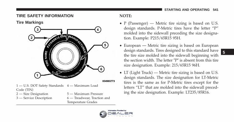
TIRE SAFETY INFORMATION
Tire Markings
NOTE:
• P (Passenger) — Metric tire sizing is based on U.S.design standards. P-Metric tires have the letter “P”molded into the sidewall preceding the size designa-tion. Example: P215/65R15 95H.
• European — Metric tire sizing is based on Europeandesign standards. Tires designed to this standard havethe tire size molded into the sidewall beginning withthe section width. The letter �P� is absent from this tiresize designation. Example: 215/65R15 96H.
• LT (Light Truck) — Metric tire sizing is based on U.S.design standards. The size designation for LT-Metrictires is the same as for P-Metric tires except for theletters “LT” that are molded into the sidewall preced-ing the size designation. Example: LT235/85R16.
1 — U.S. DOT Safety StandardsCode (TIN)
4 — Maximum Load
2 — Size Designation 5 — Maximum Pressure3 — Service Description 6 — Treadwear, Traction and
Temperature Grades
5
STARTING AND OPERATING 541
Information Provided by:
• Temporary spare tires are designed for temporaryemergency use only. Temporary high pressure com-pact spare tires have the letter “T” or “S” molded intothe sidewall preceding the size designation. Example:T145/80D18 103M.
• High flotation tire sizing is based on U.S. designstandards and it begins with the tire diameter moldedinto the sidewall. Example: 31x10.5 R15 LT.
Tire Sizing ChartEXAMPLE:
Example Size Designation: P215/65R15XL 95H, 215/65R15 96H, LT235/85R16C, T145/80D18 103M, 31x10.5 R15 LTP = Passenger car tire size based on U.S. design standards, or�....blank....� = Passenger car tire based on European design standards, orLT = Light truck tire based on U.S. design standards, orT or S = Temporary spare tire or31 = Overall diameter in inches (in)215, 235, 145 = Section width in millimeters (mm)65, 85, 80 = Aspect ratio in percent (%)
– Ratio of section height to section width of tire, or10.5 = Section width in inches (in)
542 STARTING AND OPERATING
Information Provided by:
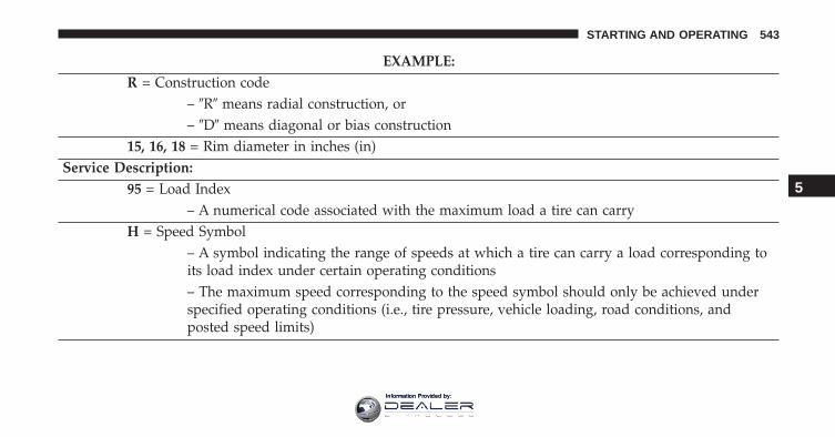
EXAMPLE:R = Construction code
– �R� means radial construction, or– �D� means diagonal or bias construction
15, 16, 18 = Rim diameter in inches (in)Service Description:
95 = Load Index– A numerical code associated with the maximum load a tire can carry
H = Speed Symbol– A symbol indicating the range of speeds at which a tire can carry a load corresponding toits load index under certain operating conditions– The maximum speed corresponding to the speed symbol should only be achieved underspecified operating conditions (i.e., tire pressure, vehicle loading, road conditions, andposted speed limits)
5
STARTING AND OPERATING 543
Information Provided by:
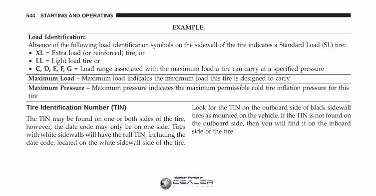
EXAMPLE:Load Identification:Absence of the following load identification symbols on the sidewall of the tire indicates a Standard Load (SL) tire:• XL = Extra load (or reinforced) tire, or• LL = Light load tire or• C, D, E, F, G = Load range associated with the maximum load a tire can carry at a specified pressureMaximum Load – Maximum load indicates the maximum load this tire is designed to carryMaximum Pressure – Maximum pressure indicates the maximum permissible cold tire inflation pressure for thistire
Tire Identification Number (TIN)
The TIN may be found on one or both sides of the tire,however, the date code may only be on one side. Tireswith white sidewalls will have the full TIN, including thedate code, located on the white sidewall side of the tire.
Look for the TIN on the outboard side of black sidewalltires as mounted on the vehicle. If the TIN is not found onthe outboard side, then you will find it on the inboardside of the tire.
544 STARTING AND OPERATING
Information Provided by:
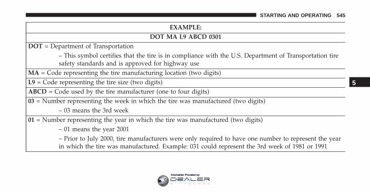
EXAMPLE:DOT MA L9 ABCD 0301
DOT = Department of Transportation– This symbol certifies that the tire is in compliance with the U.S. Department of Transportation tiresafety standards and is approved for highway use
MA = Code representing the tire manufacturing location (two digits)L9 = Code representing the tire size (two digits)ABCD = Code used by the tire manufacturer (one to four digits)03 = Number representing the week in which the tire was manufactured (two digits)
– 03 means the 3rd week01 = Number representing the year in which the tire was manufactured (two digits)
– 01 means the year 2001– Prior to July 2000, tire manufacturers were only required to have one number to represent the yearin which the tire was manufactured. Example: 031 could represent the 3rd week of 1981 or 1991
5
STARTING AND OPERATING 545
Information Provided by:
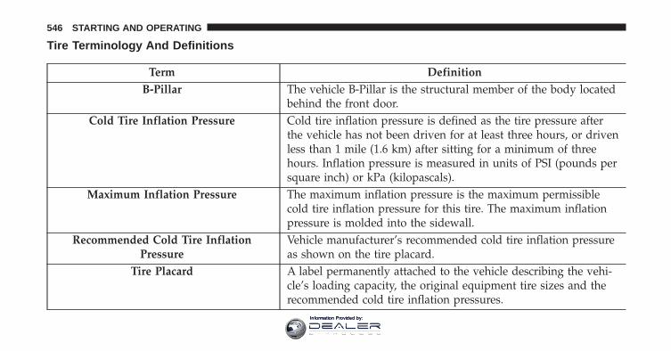
Tire Terminology And Definitions
Term DefinitionB-Pillar The vehicle B-Pillar is the structural member of the body located
behind the front door.Cold Tire Inflation Pressure Cold tire inflation pressure is defined as the tire pressure after
the vehicle has not been driven for at least three hours, or drivenless than 1 mile (1.6 km) after sitting for a minimum of threehours. Inflation pressure is measured in units of PSI (pounds persquare inch) or kPa (kilopascals).
Maximum Inflation Pressure The maximum inflation pressure is the maximum permissiblecold tire inflation pressure for this tire. The maximum inflationpressure is molded into the sidewall.
Recommended Cold Tire InflationPressure
Vehicle manufacturer’s recommended cold tire inflation pressureas shown on the tire placard.
Tire Placard A label permanently attached to the vehicle describing the vehi-cle’s loading capacity, the original equipment tire sizes and therecommended cold tire inflation pressures.
546 STARTING AND OPERATING
Information Provided by:
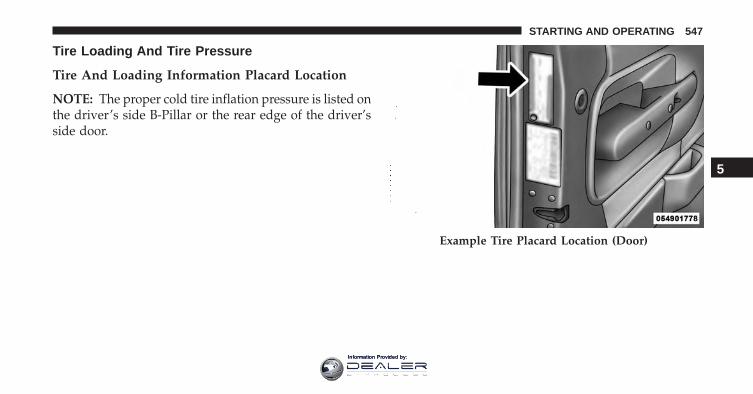
Tire Loading And Tire Pressure
Tire And Loading Information Placard Location
NOTE: The proper cold tire inflation pressure is listed onthe driver’s side B-Pillar or the rear edge of the driver’sside door.
Example Tire Placard Location (Door)
5
STARTING AND OPERATING 547
Information Provided by:
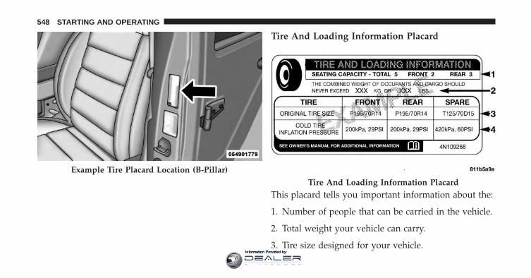
Tire And Loading Information Placard
This placard tells you important information about the:
1. Number of people that can be carried in the vehicle.
2. Total weight your vehicle can carry.
3. Tire size designed for your vehicle.
Example Tire Placard Location (B-Pillar)
Tire And Loading Information Placard
548 STARTING AND OPERATING
Information Provided by:
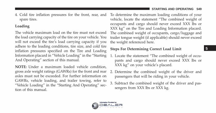
4. Cold tire inflation pressures for the front, rear, andspare tires.
Loading
The vehicle maximum load on the tire must not exceedthe load carrying capacity of the tire on your vehicle. Youwill not exceed the tire’s load carrying capacity if youadhere to the loading conditions, tire size, and cold tireinflation pressures specified on the Tire and LoadingInformation placard in “Vehicle Loading” in the “StartingAnd Operating” section of this manual.
NOTE: Under a maximum loaded vehicle condition,gross axle weight ratings (GAWRs) for the front and rearaxles must not be exceeded. For further information onGAWRs, vehicle loading, and trailer towing, refer to“Vehicle Loading” in the “Starting And Operating” sec-tion of this manual.
To determine the maximum loading conditions of yourvehicle, locate the statement “The combined weight ofoccupants and cargo should never exceed XXX lbs orXXX kg” on the Tire and Loading Information placard.The combined weight of occupants, cargo/luggage andtrailer tongue weight (if applicable) should never exceedthe weight referenced here.
Steps For Determining Correct Load Limit
1. Locate the statement “The combined weight of occu-pants and cargo should never exceed XXX lbs orXXX kg” on your vehicle’s placard.
2. Determine the combined weight of the driver andpassengers that will be riding in your vehicle.
3. Subtract the combined weight of the driver and pas-sengers from XXX lbs or XXX kg.
5
STARTING AND OPERATING 549
Information Provided by:
4. The resulting figure equals the available amount ofcargo and luggage load capacity. For example, if“XXX” amount equals 1,400 lbs (635 kg) and there willbe five 150 lb (68 kg) passengers in your vehicle, theamount of available cargo and luggage load capacityis 650 lbs (295 kg) (since 5 x 150 lbs (68 kg) = 750 lbs(340 kg), and 1400 lbs (635 kg) – 750 lbs (340 kg) =650 lbs [295 kg]).
5. Determine the combined weight of luggage and cargobeing loaded on the vehicle. That weight may notsafely exceed the available cargo and luggage loadcapacity calculated in step 4.
NOTE:
• If your vehicle will be towing a trailer, load from yourtrailer will be transferred to your vehicle. The follow-ing table shows examples on how to calculate totalload, cargo/luggage, and towing capacities of yourvehicle with varying seating configurations and num-ber and size of occupants. This table is for illustrationpurposes only and may not be accurate for the seatingand load carry capacity of your vehicle.
• For the following example, the combined weight ofoccupants and cargo should never exceed 865 lbs(392 kg).
550 STARTING AND OPERATING
Information Provided by:
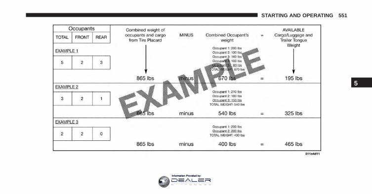
5
STARTING AND OPERATING 551
Information Provided by:
WARNING!
Overloading of your tires is dangerous. Overloadingcan cause tire failure, affect vehicle handling, andincrease your stopping distance. Use tires of therecommended load capacity for your vehicle. Neveroverload them.
TIRES — GENERAL INFORMATION
Tire Pressure
Proper tire inflation pressure is essential to the safe andsatisfactory operation of your vehicle. Four primary areasare affected by improper tire pressure:
• Safety and Vehicle Stability
• Economy
• Tread Wear
• Ride Comfort
Safety
WARNING!
• Improperly inflated tires are dangerous and cancause collisions.
• Underinflation increases tire flexing and can resultin overheating and tire failure.
• Overinflation reduces a tire’s ability to cushionshock. Objects on the road and chuckholes cancause damage that result in tire failure.
• Overinflated or underinflated tires can affect ve-hicle handling and can fail suddenly, resulting inloss of vehicle control.
• Unequal tire pressures can cause steering prob-lems. You could lose control of your vehicle.
(Continued)
552 STARTING AND OPERATING
Information Provided by:
WARNING! (Continued)• Unequal tire pressures from one side of the vehicle
to the other can cause the vehicle to drift to theright or left.
• Always drive with each tire inflated to the recom-mended cold tire inflation pressure.
Both under-inflation and over-inflation affect the stabilityof the vehicle and can produce a feeling of sluggishresponse or over responsiveness in the steering.
NOTE:
• Unequal tire pressures from side to side may causeerratic and unpredictable steering response.
• Unequal tire pressure from side to side may cause thevehicle to drift left or right.
Fuel Economy
Underinflated tires will increase tire rolling resistanceresulting in higher fuel consumption.
Tread Wear
Improper cold tire inflation pressures can cause abnor-mal wear patterns and reduced tread life, resulting in theneed for earlier tire replacement.
Ride Comfort And Vehicle Stability
Proper tire inflation contributes to a comfortable ride.Over-inflation produces a jarring and uncomfortableride.
Tire Inflation Pressures
The proper cold tire inflation pressure is listed on thedriver’s side B-Pillar or rear edge of the driver’s sidedoor.
5
STARTING AND OPERATING 553
Information Provided by:
At least once a month:
• Check and adjust tire pressure with a good qualitypocket-type pressure gauge. Do not make a visualjudgement when determining proper inflation. Tiresmay look properly inflated even when they are under-inflated.
• Inspect tires for signs of tire wear or visible damage.
CAUTION!
After inspecting or adjusting the tire pressure, al-ways reinstall the valve stem cap. This will preventmoisture and dirt from entering the valve stem,which could damage the valve stem.
Inflation pressures specified on the placard are always“cold tire inflation pressure”. Cold tire inflation pressureis defined as the tire pressure after the vehicle has notbeen driven for at least three hours, or driven less than 1
mile (1.6 km) after sitting for a minimum of three hours.The cold tire inflation pressure must not exceed themaximum inflation pressure molded into the tire side-wall.
Check tire pressures more often if subject to a wide rangeof outdoor temperatures, as tire pressures vary withtemperature changes.
Tire pressures change by approximately 1 psi (7 kPa) per12°F (7°C) of air temperature change. Keep this in mindwhen checking tire pressure inside a garage, especially inthe Winter.
Example: If garage temperature = 68°F (20°C) and theoutside temperature = 32°F (0°C) then the cold tireinflation pressure should be increased by 3 psi (21 kPa),which equals 1 psi (7 kPa) for every 12°F (7°C) for thisoutside temperature condition.
554 STARTING AND OPERATING
Information Provided by:
Tire pressure may increase from 2 to 6 psi (13 to 40 kPa)during operation. DO NOT reduce this normal pressurebuild up or your tire pressure will be too low.
Tire Pressures For High Speed Operation
The manufacturer advocates driving at safe speeds andwithin posted speed limits. Where speed limits or condi-tions are such that the vehicle can be driven at highspeeds, maintaining correct tire inflation pressure is veryimportant. Increased tire pressure and reduced vehicleloading may be required for high-speed vehicle opera-tion. Refer to your authorized tire dealer or originalequipment vehicle dealer for recommended safe operat-ing speeds, loading and cold tire inflation pressures.
WARNING!
High speed driving with your vehicle under maxi-mum load is dangerous. The added strain on yourtires could cause them to fail. You could have aserious collision. Do not drive a vehicle loaded to themaximum capacity at continuous speeds above75 mph (120 km/h).
Radial Ply Tires
WARNING!
Combining radial ply tires with other types of tireson your vehicle will cause your vehicle to handlepoorly. The instability could cause a collision. Al-ways use radial ply tires in sets of four. Nevercombine them with other types of tires.
5
STARTING AND OPERATING 555
Information Provided by:

Tire Repair
If your tire becomes damaged, it may be repaired if itmeets the following criteria:
• The tire has not been driven on when flat.
• The damage is only on the tread section of your tire(sidewall damage is not repairable).
• The puncture is no greater than a ¼ of an inch (6 mm).
Consult an authorized tire dealer for tire repairs andadditional information.
Damaged Run Flat tires, or Run Flat tires that haveexperienced a loss of pressure should be replaced imme-diately with another Run Flat tire of identical size andservice description (Load Index and Speed Symbol).
Tire Types
All Season Tires — If Equipped
All Season tires provide traction for all seasons (Spring,Summer, Fall and Winter). Traction levels may varybetween different all season tires. All season tires can beidentified by the M+S, M&S, M/S or MS designation onthe tire sidewall. Use all season tires only in sets of four;failure to do so may adversely affect the safety andhandling of your vehicle.
Summer Or Three Season Tires — If Equipped
Summer tires provide traction in both wet and dryconditions, and are not intended to be driven in snow oron ice. If your vehicle is equipped with Summer tires, beaware these tires are not designed for Winter or colddriving conditions. Install Winter tires on your vehiclewhen ambient temperatures are less than 40°F (5°C) or ifroads are covered with ice or snow. For more informa-tion, contact an authorized dealer.
556 STARTING AND OPERATING
Information Provided by:
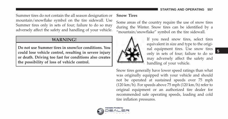
Summer tires do not contain the all season designation ormountain/snowflake symbol on the tire sidewall. UseSummer tires only in sets of four; failure to do so mayadversely affect the safety and handling of your vehicle.
WARNING!
Do not use Summer tires in snow/ice conditions. Youcould lose vehicle control, resulting in severe injuryor death. Driving too fast for conditions also createsthe possibility of loss of vehicle control.
Snow Tires
Some areas of the country require the use of snow tiresduring the Winter. Snow tires can be identified by a“mountain/snowflake” symbol on the tire sidewall.
If you need snow tires, select tiresequivalent in size and type to the origi-nal equipment tires. Use snow tiresonly in sets of four; failure to do somay adversely affect the safety andhandling of your vehicle.
Snow tires generally have lower speed ratings than whatwas originally equipped with your vehicle and shouldnot be operated at sustained speeds over 75 mph(120 km/h). For speeds above 75 mph (120 km/h) refer tooriginal equipment or an authorized tire dealer forrecommended safe operating speeds, loading and coldtire inflation pressures.
5
STARTING AND OPERATING 557
Information Provided by:
While studded tires improve performance on ice, skidand traction capability on wet or dry surfaces may bepoorer than that of non-studded tires. Some states pro-hibit studded tires; therefore, local laws should bechecked before using these tire types.
Run Flat Tires — If Equipped
Run Flat tires allow you the capability to drive 50 miles(80 km) at 50 mph (80 km/h) after a rapid loss of inflationpressure. This rapid loss of inflation is referred to as theRun Flat mode. A Run Flat mode occurs when the tireinflation pressure is of/or below 14 psi (96 kPa). Once aRun Flat tire reaches the run flat mode it has limiteddriving capabilities and needs to be replaced immedi-ately. A Run Flat tire is not repairable.
It is not recommended driving a vehicle loaded at fullcapacity or to tow a trailer while a tire is in the run flatmode.
See the tire pressure monitoring section for more infor-mation.
Spare Tires — If Equipped
NOTE: For vehicles equipped with Tire Service Kitinstead of a spare tire, please refer to “Tire Service Kit” in“What To Do In Emergencies” for further information.
CAUTION!
Because of the reduced ground clearance, do not takeyour vehicle through an automatic car wash with acompact or limited-use temporary spare installed.Damage to the vehicle may result.
558 STARTING AND OPERATING
Information Provided by:
Spare Tire Matching Original Equipped Tire AndWheel — If Equipped
Your vehicle may be equipped with a spare tire andwheel equivalent in look and function to the originalequipment tire and wheel found on the front or rear axleof your vehicle. This spare tire may be used in the tirerotation for your vehicle. If your vehicle has this option,refer to an authorized tire dealer for the recommendedtire rotation pattern.
Compact Spare Tire — If Equipped
The compact spare is for temporary emergency use only.You can identify if your vehicle is equipped with acompact spare by looking at the spare tire description onthe Tire and Loading Information Placard located on thedriver’s side door opening or on the sidewall of the tire.Compact spare tire descriptions begin with the letter “T”or “S” preceding the size designation. Example: T145/80D18 103M.
T, S = Temporary Spare Tire
Since this tire has limited tread life, the original equip-ment tire should be repaired (or replaced) and reinstalledon your vehicle at the first opportunity.
Do not install a wheel cover or attempt to mount aconventional tire on the compact spare wheel, since thewheel is designed specifically for the compact spare tire.Do not install more than one compact spare tire andwheel on the vehicle at any given time.
WARNING!
Compact spares are for temporary emergency useonly. With these spares, do not drive more than50 mph (80 km/h). Temporary use spares have limitedtread life. When the tread is worn to the tread wearindicators, the temporary use spare tire needs to be
(Continued)
5
STARTING AND OPERATING 559
Information Provided by:
WARNING! (Continued)replaced. Be sure to follow the warnings, whichapply to your spare. Failure to do so could result inspare tire failure and loss of vehicle control.
Full Size Spare — If Equipped
The full size spare is for temporary emergency use only.This tire may look like the originally equipped tire on thefront or rear axle of your vehicle, but it is not. This sparetire may have limited tread life. When the tread is wornto the tread wear indicators, the temporary use full sizespare tire needs to be replaced. Since it is not the same asyour original equipment tire, replace (or repair) theoriginal equipment tire and reinstall on the vehicle at thefirst opportunity.
Limited-Use Spare — If Equipped
The limited-use spare tire is for temporary emergencyuse only. This tire is identified by a label located on the
limited-use spare wheel. This label contains the drivinglimitations for this spare. This tire may look like theoriginal equipped tire on the front or rear axle of yourvehicle, but it is not. Installation of this limited-use sparetire affects vehicle handling. Since it is not the same asyour original equipment tire, replace (or repair) theoriginal equipment tire and reinstall on the vehicle at thefirst opportunity.
WARNING!
Limited-use spares are for emergency use only. In-stallation of this limited-use spare tire affects vehiclehandling. With this tire, do not drive more than thespeed listed on the limit-use spare wheel. Keepinflated to the cold tire inflation pressures listed onyour Tire and Loading Information Placard locatedon the driver’s side B-Pillar or the rear edge of the
(Continued)
560 STARTING AND OPERATING
Information Provided by:
WARNING! (Continued)driver’s side door. Replace (or repair) the originalequipment tire at the first opportunity and reinstall iton your vehicle. Failure to do so could result in lossof vehicle control.
Tire Spinning
When stuck in mud, sand, snow, or ice conditions, do notspin your vehicle’s wheels above 30 mph (48 km/h) orfor longer than 30 seconds continuously without stop-ping.
Refer to “Freeing A Stuck Vehicle” in “What To Do InEmergencies” for further information.
WARNING!
Fast spinning tires can be dangerous. Forces gener-ated by excessive wheel speeds may cause tire dam-age or failure. A tire could explode and injure some-one. Do not spin your vehicle’s wheels faster than30 mph (48 km/h) for more than 30 seconds continu-ously when you are stuck, and do not let anyone neara spinning wheel, no matter what the speed.
Tread Wear Indicators
Tread wear indicators are in the original equipment tiresto help you in determining when your tires should bereplaced.
5
STARTING AND OPERATING 561
Information Provided by:
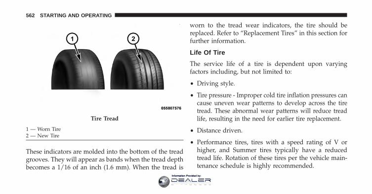
These indicators are molded into the bottom of the treadgrooves. They will appear as bands when the tread depthbecomes a 1/16 of an inch (1.6 mm). When the tread is
worn to the tread wear indicators, the tire should bereplaced. Refer to “Replacement Tires” in this section forfurther information.
Life Of Tire
The service life of a tire is dependent upon varyingfactors including, but not limited to:
• Driving style.
• Tire pressure - Improper cold tire inflation pressures cancause uneven wear patterns to develop across the tiretread. These abnormal wear patterns will reduce treadlife, resulting in the need for earlier tire replacement.
• Distance driven.
• Performance tires, tires with a speed rating of V orhigher, and Summer tires typically have a reducedtread life. Rotation of these tires per the vehicle main-tenance schedule is highly recommended.
Tire Tread
1 — Worn Tire2 — New Tire
562 STARTING AND OPERATING
Information Provided by:
WARNING!
Tires and the spare tire should be replaced after sixyears, regardless of the remaining tread. Failure tofollow this warning can result in sudden tire failure.You could lose control and have a collision resultingin serious injury or death.
Keep dismounted tires in a cool, dry place with as littleexposure to light as possible. Protect tires from contactwith oil, grease, and gasoline.
Replacement Tires
The tires on your new vehicle provide a balance of manycharacteristics. They should be inspected regularly forwear and correct cold tire inflation pressures. The manu-facturer strongly recommends that you use tires equiva-lent to the originals in size, quality and performancewhen replacement is needed. Refer to the paragraph on“Tread Wear Indicator”. Refer to the Tire and Loading
Information placard or the Vehicle Certification Label forthe size designation of your tire. The Load Index andSpeed Symbol for your tire will be found on the originalequipment tire sidewall. See the Tire Sizing Chart ex-ample found in the “Tire Safety Information” section ofthis manual for more information relating to the LoadIndex and Speed Symbol of a tire.
It is recommended to replace the two front tires or tworear tires as a pair. Replacing just one tire can seriouslyaffect your vehicle’s handling. If you ever replace awheel, make sure that the wheel’s specifications matchthose of the original wheels.
It is recommended you contact your authorized tiredealer or original equipment dealer with any questionsyou may have on tire specifications or capability. Failureto use equivalent replacement tires may adversely affectthe safety, handling, and ride of your vehicle.
5
STARTING AND OPERATING 563
Information Provided by:
WARNING!
• Do not use a tire, wheel size or rating other thanthat specified for your vehicle. Some combinationsof unapproved tires and wheels may change sus-pension dimensions and performance characteris-tics, resulting in changes to steering, handling, andbraking of your vehicle. This can cause unpredict-able handling and stress to steering and suspen-sion components. You could lose control and havea collision resulting in serious injury or death. Useonly the tire and wheel sizes with load ratingsapproved for your vehicle.
• Never use a tire with a smaller load index orcapacity, other than what was originally equippedon your vehicle. Using a tire with a smaller loadindex could result in tire overloading and failure.You could lose control and have a collision.
(Continued)
WARNING! (Continued)• Failure to equip your vehicle with tires having
adequate speed capability can result in sudden tirefailure and loss of vehicle control.
CAUTION!
Replacing original tires with tires of a different sizemay result in false speedometer and odometer read-ings.
TIRE CHAINS (TRACTION DEVICES)
Use of traction devices require sufficient tire-to-bodyclearance. Follow these recommendations to guardagainst damage.
• Traction device must be of proper size for the tire, asrecommended by the traction device manufacturer
564 STARTING AND OPERATING
Information Provided by:
• Use on Front Tires Only
• Due to limited clearance, the following traction de-vices are recommended:
Front Wheel Drive (FWD) Models
• Original equipment 225/60R17 and 225/55R18 tiresizes are not chainable.
• The use of 7mm snow chains is permitted with the useof 215/60R17 tires on size 17 x 7.0 ET41 wheels.
Four Wheel Drive (4WD) Non-Trailhawk Models with-out a Two-Speed Power Takeoff Unit
• Original equipment 225/65R17 and 225/60R18 tiresizes are not chainable.
• The use of 9mm snow chains is permitted with the useof 215/60R17 tires on size 17 x 7.0 ET41 wheels.
Four Wheel Drive (4WD) Non-Trailhawk Models with aTwo-Speed Power Takeoff Unit
• The use of 7mm snow chains is permitted with 225/65R17 and 225/60R18 tires.
Four Wheel Drive (4WD) Trailhawk Models
• The use of 9mm snow chains is permitted with the useof 225/65R17 tires on size 17 x 7.5 ET31 wheels.
CAUTION!
• Use on Front Tires Only• Damage to Front Wheel Drive (FWD) Models may
result if tire chains or traction devices are used withoriginal equipment size tires.
• Damage to Four Wheel Drive (4WD) Models with-out a Two-Speed Power Takeoff Unit may result if
(Continued)
5
STARTING AND OPERATING 565
Information Provided by:
CAUTION! (Continued)tire chains or traction devices are used with origi-nal equipment size tires.
• Damage to Four Wheel Drive (4WD) TrailhawkModels may result if tire chains or traction devicesare used with original equipment size tires.
WARNING!
Using tires of different size and type (M+S, Snow)between front and rear axles can cause unpredictablehandling. You could lose control and have a collision.
CAUTION!
To avoid damage to your vehicle or tires, observe thefollowing precautions:• Because of restricted traction device clearance be-
tween tires and other suspension components, it isimportant that only traction devices in good condi-tion are used. Broken devices can cause seriousdamage. Stop the vehicle immediately if noiseoccurs that could indicate device breakage. Removethe damaged parts of the device before further use.
• Install device as tightly as possible and then re-tighten after driving about ½ mile (0.8 km).
• Do not exceed 30 mph (48 km/h).• Drive cautiously and avoid severe turns and large
bumps, especially with a loaded vehicle.• Do not drive for a prolonged period on dry
pavement.
(Continued)
566 STARTING AND OPERATING
Information Provided by:
CAUTION! (Continued)• Observe the traction device manufacturer’s instruc-
tions on the method of installation, operatingspeed, and conditions for use. Always use thesuggested operating speed of the device manufac-turer’s if it is less than 30 mph (48 km/h).
• Do not use traction devices on a compact spare tire.
TIRE ROTATION RECOMMENDATIONS
The tires on the front and rear of your vehicle operate atdifferent loads and perform different steering, handling,and braking functions. For these reasons, they wear atunequal rates.
These effects can be reduced by timely rotation of tires.The benefits of rotation are especially worthwhile withaggressive tread designs such as those on On/Off Roadtype tires. Rotation will increase tread life, help to main-tain mud, snow, and wet traction levels, and contribute toa smooth, quiet ride.
Refer to the “Maintenance Schedule” for the propermaintenance intervals. The reasons for any rapid orunusual wear should be corrected prior to rotation beingperformed.
The suggested Front Wheel Drive (FWD) rotationmethod is the “forward cross” shown in the followingdiagram. This rotation pattern does not apply to somedirectional tires that must not be reversed.
5
STARTING AND OPERATING 567
Information Provided by:
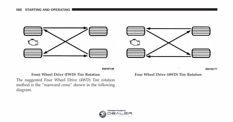
The suggested Four Wheel Drive (4WD) Tire rotationmethod is the “rearward cross” shown in the followingdiagram.
Front Wheel Drive (FWD) Tire Rotation Four Wheel Drive (4WD) Tire Rotation
568 STARTING AND OPERATING
Information Provided by:
CAUTION!
Proper operation of four-wheel drive vehicles de-pends on tires of equal size, type and circumferenceon each wheel. Any difference in tire size can causedamage to the power transfer unit. Tire rotationschedule should be followed to balance tire wear.
TIRE PRESSURE MONITOR SYSTEM (TPMS)
The Tire Pressure Monitor System (TPMS) will warn thedriver of a low tire pressure based on the vehicle recom-mended cold placard pressure.
The tire pressure will vary with temperature by approxi-mately 1 psi (7 kPa) for every 12°F (6.5°C). This meansthat when the outside temperature decreases, the tirepressure will decrease. Tire pressure should always be setbased on cold inflation tire pressure. This is defined asthe tire pressure after the vehicle has not been driven for
at least three hours, or driven less than 1 mile (1.6 km)after a three hour period. The cold tire inflation pressuremust not exceed the maximum inflation pressure moldedinto the tire sidewall. Refer to “Tires – General Informa-tion” in “Starting And Operating” for information onhow to properly inflate the vehicle’s tires. The tirepressure will also increase as the vehicle is driven. This isnormal and there should be no adjustment for thisincreased pressure.
The TPMS will warn the driver of a low tire pressure ifthe tire pressure falls below the low-pressure warninglimit for any reason, including low temperature effectsand natural pressure loss through the tire.
The TPMS will continue to warn the driver of low tirepressure as long as the condition exists, and will not turnoff until the tire pressure is at or above the recommendedcold placard pressure. Once the low tire pressure warn-ing (Tire Pressure Monitoring Telltale Light) illuminates,
5
STARTING AND OPERATING 569
Information Provided by:
you must increase the tire pressure to the recommendedcold placard pressure in order for the “Tire PressureMonitoring Telltale Light” to turn off.
NOTE: When filling warm tires, the tire pressure mayneed to be increased up to an additional 4 psi (30 kPa)above the recommended cold placard pressure in orderto turn the Tire Pressure Monitoring Telltale Light off.
The system will automatically update and the “TirePressure Monitoring Telltale Light” will turn off once thesystem receives the updated tire pressures. The vehiclemay need to be driven for up to 20 minutes above 15 mph(24 km/h) in order for the TPMS to receive this informa-tion.
For example, your vehicle may have a recommended cold(parked for more than three hours) placard pressure of 33psi (227 kPa). If the ambient temperature is 68°F (20°C) andthe measured tire pressure is 28 psi (193 kPa), a tempera-ture drop to 20°F (-7°C) will decrease the tire pressure to
approximately 24 psi (165 kPa). This tire pressure is lowenough to turn ON the “Tire Pressure Monitoring TelltaleLight.” Driving the vehicle may cause the tire pressure torise to approximately 28 psi (193 kPa), but the “TirePressure Monitoring Telltale Light” will still be on. In thissituation, the “Tire Pressure Monitoring Telltale Light” willturn off only after the tires are inflated to the vehicle’srecommended cold placard pressure value.
NOTE: When filling warm tires, the tire pressure mayneed to be increased up to an additional 4 psi (30 kPa)above the recommended cold placard pressure in orderto turn the Tire Pressure Monitoring Telltale Light off.
CAUTION!
• The TPMS has been optimized for the originalequipment tires and wheels. TPMS pressures andwarning have been established for the tire size
(Continued)
570 STARTING AND OPERATING
Information Provided by:
CAUTION! (Continued)equipped on your vehicle. Undesirable system op-eration or sensor damage may result when usingreplacement equipment that is not of the same size,type, and/or style. Aftermarket wheels can causesensor damage.
• Using aftermarket tire sealants may cause the TirePressure Monitoring System (TPMS) sensor to be-come inoperable. After using an aftermarket tiresealant it is recommended that you take yourvehicle to an authorized dealership to have yoursensor function checked.
• After inspecting or adjusting the tire pressure al-ways reinstall the valve stem cap. This will preventmoisture and dirt from entering the valve stem,which could damage the TPMS sensor.
NOTE:
• The TPMS is not intended to replace normal tire careand maintenance, or to provide warning of a tirefailure or condition.
• The TPMS should not be used as a tire pressure gaugewhile adjusting your tire pressure.
• Driving on a significantly underinflated tire causes thetire to overheat and can lead to tire failure. Underin-flation also reduces fuel efficiency and tire tread life,and may affect the vehicle’s handling and stoppingability.
• The TPMS is not a substitute for proper tire mainte-nance, and it is the driver’s responsibility to maintaincorrect tire pressure using an accurate tire pressuregauge, even if underinflation has not reached the levelto trigger illumination of the “Tire Pressure Monitor-ing Telltale Light”.
5
STARTING AND OPERATING 571
Information Provided by:
• Seasonal temperature changes will affect tire pressure,and the TPMS will monitor the actual tire pressure inthe tire.
Premium System — If Equipped
The Tire Pressure Monitor System (TPMS) uses wirelesstechnology with wheel rim mounted electronic sensors tomonitor tire pressure levels. Sensors, mounted to eachwheel as part of the valve stem, transmit tire pressurereadings to the receiver module.
NOTE: It is particularly important for you to check thetire pressure in all of the tires on your vehicle monthlyand to maintain the proper pressure.
The TPMS consists of the following components:
• Receiver Module
• Four Tire Pressure Monitoring Sensors
• Various Tire Pressure Monitoring System messages,which display in the Electronic Vehicle InformationCenter (EVIC) or Driver Information Display (DID).
• Tire Pressure Monitoring Telltale Light
Tire Pressure Monitoring Low Pressure Warnings
The “Tire Pressure Monitoring Telltale Light” willilluminate in the instrument cluster and a chime
will sound when tire pressure is low in one or more of thefour active road tires. In addition, the Electronic VehicleInformation Center (EVIC)/Driver information Display(DID) will display a �Tire Low� message for a minimumof five seconds, an �Inflate to XX� message and a graphicshowing the pressure values of each tire with the low tirepressure values in a different color.
572 STARTING AND OPERATING
Information Provided by:
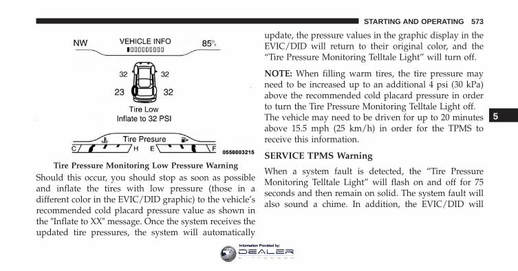
Should this occur, you should stop as soon as possibleand inflate the tires with low pressure (those in adifferent color in the EVIC/DID graphic) to the vehicle’srecommended cold placard pressure value as shown inthe �Inflate to XX� message. Once the system receives theupdated tire pressures, the system will automatically
update, the pressure values in the graphic display in theEVIC/DID will return to their original color, and the“Tire Pressure Monitoring Telltale Light” will turn off.
NOTE: When filling warm tires, the tire pressure mayneed to be increased up to an additional 4 psi (30 kPa)above the recommended cold placard pressure in orderto turn the Tire Pressure Monitoring Telltale Light off.The vehicle may need to be driven for up to 20 minutesabove 15.5 mph (25 km/h) in order for the TPMS toreceive this information.
SERVICE TPMS Warning
When a system fault is detected, the “Tire PressureMonitoring Telltale Light” will flash on and off for 75seconds and then remain on solid. The system fault willalso sound a chime. In addition, the EVIC/DID will
Tire Pressure Monitoring Low Pressure Warning
5
STARTING AND OPERATING 573
Information Provided by:
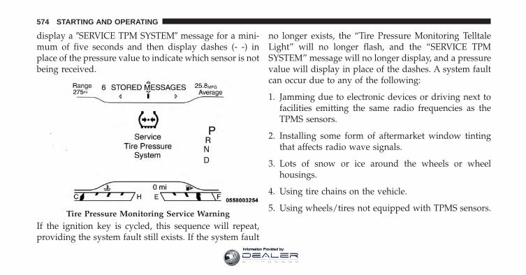
display a �SERVICE TPM SYSTEM� message for a mini-mum of five seconds and then display dashes (- -) inplace of the pressure value to indicate which sensor is notbeing received.
If the ignition key is cycled, this sequence will repeat,providing the system fault still exists. If the system fault
no longer exists, the “Tire Pressure Monitoring TelltaleLight” will no longer flash, and the “SERVICE TPMSYSTEM” message will no longer display, and a pressurevalue will display in place of the dashes. A system faultcan occur due to any of the following:
1. Jamming due to electronic devices or driving next tofacilities emitting the same radio frequencies as theTPMS sensors.
2. Installing some form of aftermarket window tintingthat affects radio wave signals.
3. Lots of snow or ice around the wheels or wheelhousings.
4. Using tire chains on the vehicle.
5. Using wheels/tires not equipped with TPMS sensors.Tire Pressure Monitoring Service Warning
574 STARTING AND OPERATING
Information Provided by:
Vehicles With Matching Full-Size Spare
1. The matching full size spare wheel and tire assemblyhas a tire pressure monitoring sensor that can bemonitored by the TPMS.
2. If you install the full size spare in place of a road tirethat has a pressure below the low-pressure warninglimit, a chime will sound and the “TPMS TelltaleLight” will turn on upon the next ignition key cycle. Inaddition, the EVIC/DID will display a Tire Lowmessage, an �Inflate to XX� message and a graphicshowing the low tire pressure value in a differentcolor.
3. After driving the vehicle for up to 20 minutes above15.5 mph (25 km/h) the “TPMS Telltale Light” willturn OFF, as long as no tire pressure is below thelow-pressure warning limit in any of the four activeroad tires.
4. The EVIC/DID will display a graphic showing the tirepressure value in the same color as the other pressurevalues in place of the different color low tire pressurevalue. The EVIC/DID will also display a “SPARELOW PRESSURE” message to remind you to servicethe flat tire.
Vehicles With Compact Spare or Non-Matching FullSize Spare
1. The compact spare tire or non-matching full size doesnot have a tire pressure monitoring sensor. Therefore,the TPMS will not monitor the pressure in the compactspare tire.
2. If you install the compact or non-matching full sizespare tire in place of a road tire that has a pressurebelow the low-pressure warning limit, upon the nextignition key cycle, the “TPMS Telltale Light” willremain on and a chime will sound. In addition, the
5
STARTING AND OPERATING 575
Information Provided by:
graphic in the EVIC/DID will still display a differentcolor pressure value and an �Inflate to XX� message.
3. After driving the vehicle for up to 20 minutes above15.5 mph (25 km/h), the “TPMS Telltale Light” willflash on and off for 75 seconds and then remain onsolid. In addition, the EVIC/DID will display a “SER-VICE TPM SYSTEM” message for five seconds andthen display dashes (- -) in place of the pressure value.
4. For each subsequent ignition key cycle, a chime willsound, the “TPMS Telltale Light” will flash on and offfor 75 seconds and then remain on solid, and theEVIC/DID will display a “SERVICE TPM SYSTEM”message for five seconds and then display dashes (- -)in place of the pressure value.
5. Once you repair or replace the original road tire andreinstall it on the vehicle in place of the compact spareor non-matching full size, the TPMS will updateautomatically. In addition, the “TPMS Telltale Light”
will turn off and the graphic in the EVIC/DID willdisplay a new pressure value instead of dashes (- -), aslong as no tire pressure is below the low-pressurewarning limit in any of the four active road tires. Thevehicle may need to be driven for up to 20 minutesabove 15.5 mph (25 km/h) in order for the TPMS toreceive this information.
General Information
This device complies with Part 15 of the FCC rules andRSS-210 of Industry Canada. Operation is subject to thefollowing two conditions:
(1) This device may not cause harmful interference.
(2) This device must accept any interference received,including interference that may cause undesired operation.
NOTE: Changes or modifications not expressly approvedby the party responsible for compliance could void theuser’s authority to operate the equipment.
576 STARTING AND OPERATING
Information Provided by:
FUEL REQUIREMENTS
2.4L and 3.2L Engines
This engine is designed to meet all emis-sions regulations and provide optimumfuel economy and performance when us-ing high quality unleaded “Regular” gaso-line having a posted octane number of 87
as specified by the (R+M)/2 method. The use of higheroctane “Premium” gasoline is not required, as it will notprovide any benefit over “Regular” gasoline in theseengines.
While operating on gasoline with an octane number of87, hearing a light knocking sound from the engine is nota cause for concern. However, if the engine is heardmaking a heavy knocking sound, see your dealer imme-diately. Use of gasoline with an octane number lowerthan 87 can cause engine failure and may void or not becovered by the New Vehicle Limited Warranty.
Poor quality gasoline can cause problems such as hardstarting, stalling, and hesitations. If you experience thesesymptoms, try another brand of gasoline before consid-ering service for the vehicle.
Reformulated Gasoline
Many areas of the country require the use of cleanerburning gasoline referred to as “Reformulated Gasoline”.Reformulated gasoline contains oxygenates and are spe-cifically blended to reduce vehicle emissions and im-prove air quality.
The use of reformulated gasoline is recommended. Prop-erly blended reformulated gasoline will provide im-proved performance and durability of engine and fuelsystem components.
5
STARTING AND OPERATING 577
Information Provided by:
Gasoline/Oxygenate Blends
Some fuel suppliers blend unleaded gasoline with oxy-genates such as ethanol.
CAUTION!
DO NOT use gasoline containing methanol or gaso-line containing more than 15% ethanol (E-15). Use ofthese blends may result in starting and drivabilityproblems, damage critical fuel system components,cause emissions to exceed the applicable standard,and/or cause the “Malfunction Indicator Light” toilluminate. Please observe pump labels as theyshould clearly communicate if a fuel contains greaterthan 15% ethanol (E-15).
Problems that result from using gasoline containing morethan 15% ethanol (E-15) or gasoline containing methanol
are not the responsibility of the manufacturer and mayvoid or not be covered under New Vehicle LimitedWarranty.
E-85 Usage In Non-Flex Fuel Vehicles
Non-Flex Fuel Vehicles (FFV) are compatible with gaso-line containing up to 15% ethanol (E-15). Gasoline withhigher ethanol content may void the New Vehicle Lim-ited Warranty.
If a Non-FFV vehicle is inadvertently fueled with E-85fuel, the engine will have some or all of these symptoms:
• Operate in a lean mode.
• OBD II “Malfunction Indicator Light” on.
• Poor engine performance.
• Poor cold start and cold drivability.
• Increased risk for fuel system component corrosion.
578 STARTING AND OPERATING
Information Provided by:
MMT In Gasoline
Methylcyclopentadienyl Manganese Tricarbonyl (MMT)is a manganese-containing metallic additive that isblended into some gasoline to increase octane. Gasolineblended with MMT provides no performance advantagebeyond gasoline of the same octane number withoutMMT. Gasoline blended with MMT reduces spark pluglife and reduces emissions system performance in somevehicles. The manufacturer recommends that gasolinewithout MMT be used in your vehicle. The MMT contentof gasoline may not be indicated on the gasoline pump,therefore, you should ask your gasoline retailer whetherthe gasoline contains MMT. MMT is prohibited in Federaland California reformulated gasoline.
Materials Added To Fuel
Besides using unleaded gasoline with the proper octanerating, gasolines that contain detergents, corrosion andstability additives are recommended. Using gasolines
that have these additives will help improve fueleconomy, reduce emissions, and maintain vehicle perfor-mance. Designated TOP TIER Detergent Gasoline con-tains a higher level of detergents to further aide inminimizing engine and fuel system deposits. When avail-able the usage of Top Tier Detergent gasoline is recom-mended. Visit www.toptiergas.com for a list of TOP TIERDetergent Gasoline Retailers.
Indiscriminate use of fuel system cleaning agents shouldbe avoided. Many of these materials intended for gumand varnish removal may contain active solvents orsimilar ingredients. These can harm fuel system gasketand diaphragm materials.
5
STARTING AND OPERATING 579
Information Provided by:
Fuel System Cautions
CAUTION!
Follow these guidelines to maintain your vehicle’sperformance:• The use of leaded gasoline is prohibited by
Federal law. Using leaded gasoline can impairengine performance and damage the emissionscontrol system.
• An out-of-tune engine or certain fuel or ignitionmalfunctions can cause the catalytic converter tooverheat. If you notice a pungent burning odor orsome light smoke, your engine may be out of tuneor malfunctioning and may require immediate ser-vice. Contact your authorized dealer for serviceassistance.
(Continued)
CAUTION! (Continued)• The use of fuel additives, which are now being
sold as octane enhancers, is not recommended.Most of these products contain high concentrationsof methanol. Fuel system damage or vehicle perfor-mance problems resulting from the use of suchfuels or additives is not the responsibility of themanufacturer and may void or not be coveredunder the New Vehicle Limited Warranty.
NOTE: Intentional tampering with the emissions controlsystem can result in civil penalties being assessed againstyou.
580 STARTING AND OPERATING
Information Provided by:
Carbon Monoxide Warnings
WARNING!
Carbon monoxide (CO) in exhaust gases is deadly.Follow the precautions below to prevent carbonmonoxide poisoning:• Do not inhale exhaust gases. They contain carbon
monoxide, a colorless and odorless gas, which cankill. Never run the engine in a closed area, such asa garage, and never sit in a parked vehicle with theengine running for an extended period. If thevehicle is stopped in an open area with the enginerunning for more than a short period, adjust theventilation system to force fresh, outside air intothe vehicle.
• Guard against carbon monoxide with proper main-tenance. Have the exhaust system inspected every
(Continued)
WARNING! (Continued)time the vehicle is raised. Have any abnormalconditions repaired promptly. Until repaired, drivewith all side windows fully open.
FLEXIBLE FUEL (2.4L ENGINE ONLY) — IFEQUIPPED
E-85 General Information
The information in this section is unique for Flexible Fuelvehicles only. These vehicles can be identified by aunique fuel filler door label that states Ethanol (E-85) orUnleaded Gasoline Only and a yellow fuel cap. Pleaserefer to the other sections of this manual for informationon features that are common between Flexible Fuel andnon-Flexible Fuel powered vehicles.
5
STARTING AND OPERATING 581
Information Provided by:
CAUTION!
Only vehicles with the E-85 fuel filler door label or ayellow gas cap can operate on E-85.
Ethanol Fuel (E-85)
E-85 is a mixture of approximately 85% ethanol and 15%unleaded gasoline.
WARNING!
Ethanol vapors are extremely flammable and couldcause serious personal injury. Never have any smok-ing materials lit or products that can cause spark in ornear the vehicle when removing the fuel filler tubecap (gas cap) or filling the tank. Do not use E-85 as acleaning agent and never use it near an open flame.
Fuel Requirements
If your vehicle is E-85 compatible, it will operate onunleaded gasoline with any octane rating, or solely E-85fuel, or any mixture of these fuels.
For best results, avoid fueling patterns alternatingbetween E-85 and unleaded gasoline.
When switching fuel types:
• Add 5 gallons (19 liters) or more when refueling.
• Drive the vehicle immediately after refueling for atleast 5 miles (8 km).
Observing these precautions will avoid possible hardstarting and/or driveability problems during warm up.
582 STARTING AND OPERATING
Information Provided by:
NOTE:
• Use seasonally adjusted E-85 fuel (ASTM D5798). Withnon-seasonally adjusted E-85 fuel, hard starting andrough idle following start up may be experienced evenif the above recommendations are followed, especiallywhen the ambient temperature is below 32°F (0°C).
• Some additives used in regular gasoline are not fullycompatible with E-85 and may form deposits in yourengine. To eliminate driveability issues that may becaused by these deposits, a supplemental gasolineadditive, such as MOPAR Injector Cleanup or Techronmay be used.
Selection Of Engine Oil For Flexible Fuel Vehicles(E-85) And Gasoline Vehicles
FFV vehicles operated on E-85 require specially formu-lated engine oils. These special requirements are includedin MOPAR engine oils, and in equivalent oils meeting
FCA US Material Standard MS-6395. It is recommendedthat engine oils that are API Certified and meet therequirements of Material Standard MS-6395 be used.MS-6395 contains additional requirements, developedduring extensive fleet testing, to provide additional pro-tection to FCA US LLC engines.
Starting
The characteristics of E-85 fuel make it unsuitable for usewhen ambient temperatures fall below 0°F (-18°C). In therange of 0°F (-18°C) to 32°F (0°C), an increase in the timeit takes for your engine to start may be experienced, anda deterioration in driveability (sags and/or hesitations)until the engine is fully warmed up. These issues may beimproved with the use of seasonally adjusted E-85 fuel.
NOTE: Use of the engine block heater (if equipped) mayimprove engine start time when using E-85 fuel when theambient temperature is less than 32°F (0°C).
5
STARTING AND OPERATING 583
Information Provided by:
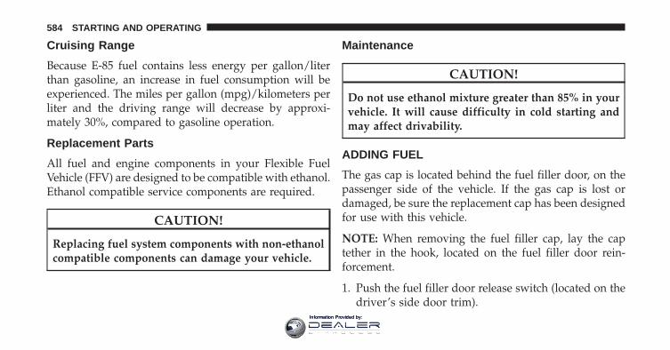
Cruising Range
Because E-85 fuel contains less energy per gallon/literthan gasoline, an increase in fuel consumption will beexperienced. The miles per gallon (mpg)/kilometers perliter and the driving range will decrease by approxi-mately 30%, compared to gasoline operation.
Replacement Parts
All fuel and engine components in your Flexible FuelVehicle (FFV) are designed to be compatible with ethanol.Ethanol compatible service components are required.
CAUTION!
Replacing fuel system components with non-ethanolcompatible components can damage your vehicle.
Maintenance
CAUTION!
Do not use ethanol mixture greater than 85% in yourvehicle. It will cause difficulty in cold starting andmay affect drivability.
ADDING FUEL
The gas cap is located behind the fuel filler door, on thepassenger side of the vehicle. If the gas cap is lost ordamaged, be sure the replacement cap has been designedfor use with this vehicle.
NOTE: When removing the fuel filler cap, lay the captether in the hook, located on the fuel filler door rein-forcement.
1. Push the fuel filler door release switch (located on thedriver’s side door trim).
584 STARTING AND OPERATING
Information Provided by:
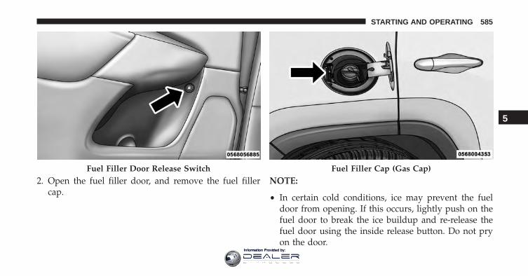
2. Open the fuel filler door, and remove the fuel fillercap.
NOTE:
• In certain cold conditions, ice may prevent the fueldoor from opening. If this occurs, lightly push on thefuel door to break the ice buildup and re-release thefuel door using the inside release button. Do not pryon the door.
Fuel Filler Door Release Switch Fuel Filler Cap (Gas Cap)
5
STARTING AND OPERATING 585
Information Provided by:
• When the fuel nozzle “clicks” or shuts off, the fuel tankis full.
• Tighten the gas cap about one quarter turn until youhear one click. This is an indication that the cap isproperly tightened.
• If the gas cap is not tightened properly, the MIL willcome on. Be sure the gas cap is tightened every timethe vehicle is refueled.
CAUTION!
• Damage to the fuel system or emission controlsystem could result from using an improper fuelfiller cap. A poorly fitting cap could let impuritiesinto the fuel system. Also, a poorly fitting aftermar-ket cap can cause the “Malfunction Indicator Light(MIL)” to illuminate, due to fuel vapors escapingfrom the system.
• A poorly fitting fuel filler cap may cause the MIL toturn on.
• To avoid fuel spillage and overfilling, do not “topoff” the fuel tank after filling.
586 STARTING AND OPERATING
Information Provided by:
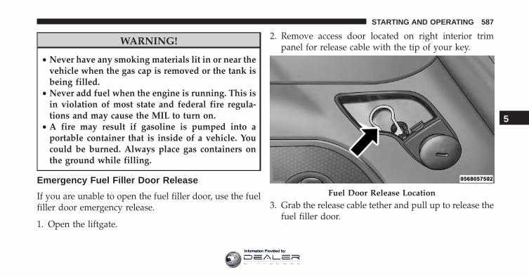
WARNING!
• Never have any smoking materials lit in or near thevehicle when the gas cap is removed or the tank isbeing filled.
• Never add fuel when the engine is running. This isin violation of most state and federal fire regula-tions and may cause the MIL to turn on.
• A fire may result if gasoline is pumped into aportable container that is inside of a vehicle. Youcould be burned. Always place gas containers onthe ground while filling.
Emergency Fuel Filler Door Release
If you are unable to open the fuel filler door, use the fuelfiller door emergency release.
1. Open the liftgate.
2. Remove access door located on right interior trimpanel for release cable with the tip of your key.
3. Grab the release cable tether and pull up to release thefuel filler door.
Fuel Door Release Location
5
STARTING AND OPERATING 587
Information Provided by:
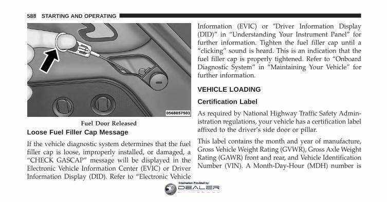
Loose Fuel Filler Cap Message
If the vehicle diagnostic system determines that the fuelfiller cap is loose, improperly installed, or damaged, a“CHECK GASCAP” message will be displayed in theElectronic Vehicle Information Center (EVIC) or DriverInformation Display (DID). Refer to “Electronic Vehicle
Information (EVIC) or �Driver Information Display(DID)” in “Understanding Your Instrument Panel” forfurther information. Tighten the fuel filler cap until a“clicking” sound is heard. This is an indication that thefuel filler cap is properly tightened. Refer to “OnboardDiagnostic System” in “Maintaining Your Vehicle” forfurther information.
VEHICLE LOADING
Certification Label
As required by National Highway Traffic Safety Admin-istration regulations, your vehicle has a certification labelaffixed to the driver’s side door or pillar.
This label contains the month and year of manufacture,Gross Vehicle Weight Rating (GVWR), Gross Axle WeightRating (GAWR) front and rear, and Vehicle IdentificationNumber (VIN). A Month-Day-Hour (MDH) number is
Fuel Door Released
588 STARTING AND OPERATING
Information Provided by:
included on this label and indicates the Month, Day andHour of manufacture. The bar code that appears on thebottom of the label is your VIN.
Gross Vehicle Weight Rating (GVWR)
The GVWR is the total permissible weight of your vehicleincluding driver, passengers, vehicle, options and cargo.The label also specifies maximum capacities of front andrear axle systems (GAWR). Total load must be limited soGVWR and front and rear GAWR are not exceeded.
Payload
The payload of a vehicle is defined as the allowable loadweight a truck can carry, including the weight of thedriver, all passengers, options and cargo.
Gross Axle Weight Rating (GAWR)
The GAWR is the maximum permissible load on the frontand rear axles. The load must be distributed in the cargoarea so that the GAWR of each axle is not exceeded.
Each axle GAWR is determined by the components in thesystem with the lowest load carrying capacity (axle,springs, tires or wheels). Heavier axles or suspensioncomponents sometimes specified by purchasers for in-creased durability does not necessarily increase the vehi-cle’s GVWR.
Tire Size
The tire size on the Vehicle Certification Label representsthe actual tire size on your vehicle. Replacement tiresmust be equal to the load capacity of this tire size.
Rim Size
This is the rim size that is appropriate for the tire sizelisted.
Inflation Pressure
This is the cold tire inflation pressure for your vehicle forall loading conditions up to full GAWR.
5
STARTING AND OPERATING 589
Information Provided by:
Curb Weight
The curb weight of a vehicle is defined as the total weightof the vehicle with all fluids, including vehicle fuel, at fullcapacity conditions, and with no occupants or cargoloaded into the vehicle. The front and rear curb weightvalues are determined by weighing your vehicle on acommercial scale before any occupants or cargo areadded.
Loading
The actual total weight and the weight of the front andrear of your vehicle at the ground can best be determinedby weighing it when it is loaded and ready for operation.
The entire vehicle should first be weighed on a commer-cial scale to insure that the GVWR has not been exceeded.The weight on the front and rear of the vehicle shouldthen be determined separately to be sure that the load isproperly distributed over the front and rear axle. Weigh-ing the vehicle may show that the GAWR of either the
front or rear axles has been exceeded but the total load iswithin the specified GVWR. If so, weight must be shiftedfrom front to rear or rear to front as appropriate until thespecified weight limitations are met. Store the heavieritems down low and be sure that the weight is distributedequally. Stow all loose items securely before driving.
Improper weight distributions can have an adverse effecton the way your vehicle steers and handles and the waythe brakes operate.
CAUTION!
Do not load your vehicle any heavier than the GVWRor the maximum front and rear GAWR. If you do,parts on your vehicle can break, or it can change theway your vehicle handles. This could cause you tolose control. Also overloading can shorten the life ofyour vehicle.
590 STARTING AND OPERATING
Information Provided by:
TRAILER TOWING
In this section you will find safety tips and informationon limits to the type of towing you can reasonably dowith your vehicle. Before towing a trailer, carefullyreview this information to tow your load as efficientlyand safely as possible.
To maintain the New Vehicle Limited Warranty coverage,follow the requirements and recommendations in thismanual concerning vehicles used for trailer towing.
Common Towing Definitions
The following trailer towing related definitions will assistyou in understanding the following information:
Gross Vehicle Weight Rating (GVWR)
The GVWR is the total allowable weight of your vehicle.This includes driver, passengers, cargo and tongueweight. The total load must be limited so that you do not
exceed the GVWR. Refer to “Vehicle Loading/VehicleCertification Label” in “Starting And Operating” forfurther information.
Gross Trailer Weight (GTW)
The GTW is the weight of the trailer plus the weight of allcargo, consumables, and equipment (permanent or tem-porary) loaded in or on the trailer in its �loaded andready for operation� condition.
The recommended way to measure GTW is to put yourfully loaded trailer on a vehicle scale. The entire weightof the trailer must be supported by the scale.
WARNING!
If the Gross Trailer Weight (GTW) is 3,500 lbs(1 587 kg) or more, it is mandatory to use a weight-distributing hitch to ensure stable handling of your
(Continued)
5
STARTING AND OPERATING 591
Information Provided by:
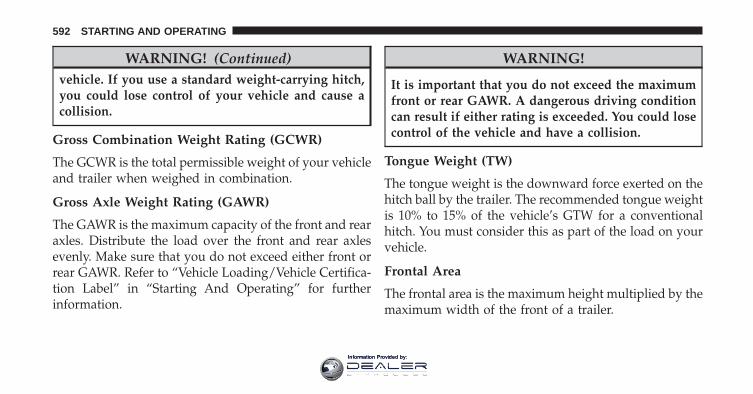
WARNING! (Continued)vehicle. If you use a standard weight-carrying hitch,you could lose control of your vehicle and cause acollision.
Gross Combination Weight Rating (GCWR)
The GCWR is the total permissible weight of your vehicleand trailer when weighed in combination.
Gross Axle Weight Rating (GAWR)
The GAWR is the maximum capacity of the front and rearaxles. Distribute the load over the front and rear axlesevenly. Make sure that you do not exceed either front orrear GAWR. Refer to “Vehicle Loading/Vehicle Certifica-tion Label” in “Starting And Operating” for furtherinformation.
WARNING!
It is important that you do not exceed the maximumfront or rear GAWR. A dangerous driving conditioncan result if either rating is exceeded. You could losecontrol of the vehicle and have a collision.
Tongue Weight (TW)
The tongue weight is the downward force exerted on thehitch ball by the trailer. The recommended tongue weightis 10% to 15% of the vehicle’s GTW for a conventionalhitch. You must consider this as part of the load on yourvehicle.
Frontal Area
The frontal area is the maximum height multiplied by themaximum width of the front of a trailer.
592 STARTING AND OPERATING
Information Provided by:
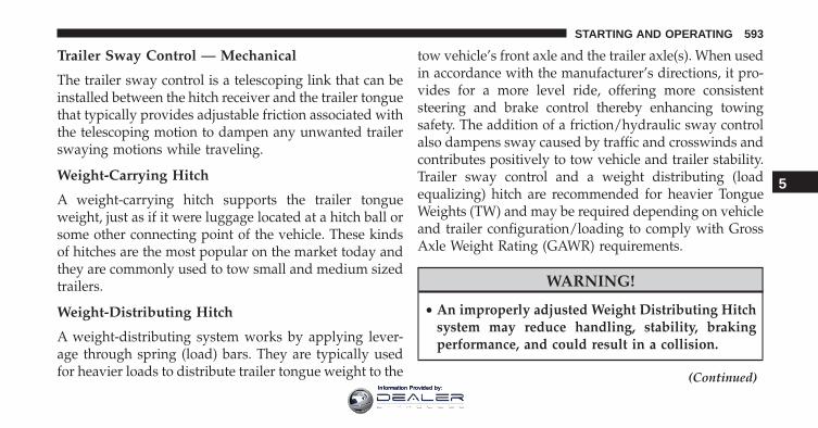
Trailer Sway Control — Mechanical
The trailer sway control is a telescoping link that can beinstalled between the hitch receiver and the trailer tonguethat typically provides adjustable friction associated withthe telescoping motion to dampen any unwanted trailerswaying motions while traveling.
Weight-Carrying Hitch
A weight-carrying hitch supports the trailer tongueweight, just as if it were luggage located at a hitch ball orsome other connecting point of the vehicle. These kindsof hitches are the most popular on the market today andthey are commonly used to tow small and medium sizedtrailers.
Weight-Distributing Hitch
A weight-distributing system works by applying lever-age through spring (load) bars. They are typically usedfor heavier loads to distribute trailer tongue weight to the
tow vehicle’s front axle and the trailer axle(s). When usedin accordance with the manufacturer’s directions, it pro-vides for a more level ride, offering more consistentsteering and brake control thereby enhancing towingsafety. The addition of a friction/hydraulic sway controlalso dampens sway caused by traffic and crosswinds andcontributes positively to tow vehicle and trailer stability.Trailer sway control and a weight distributing (loadequalizing) hitch are recommended for heavier TongueWeights (TW) and may be required depending on vehicleand trailer configuration/loading to comply with GrossAxle Weight Rating (GAWR) requirements.
WARNING!
• An improperly adjusted Weight Distributing Hitchsystem may reduce handling, stability, brakingperformance, and could result in a collision.
(Continued)
5
STARTING AND OPERATING 593
Information Provided by:
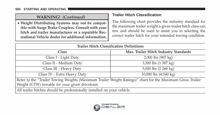
WARNING! (Continued)• Weight Distributing Systems may not be compat-
ible with Surge Brake Couplers. Consult with yourhitch and trailer manufacturer or a reputable Rec-reational Vehicle dealer for additional information.
Trailer Hitch Classification
The following chart provides the industry standard forthe maximum trailer weight a given trailer hitch class cantow and should be used to assist you in selecting thecorrect trailer hitch for your intended towing condition.
Trailer Hitch Classification DefinitionsClass Max. Trailer Hitch Industry Standards
Class I - Light Duty 2,000 lbs (907 kg)Class II - Medium Duty 3,500 lbs (1 587 kg)Class III - Heavy Duty 5,000 lbs (2 268 kg)
Class IV - Extra Heavy Duty 10,000 lbs (4 540 kg)Refer to the “Trailer Towing Weights (Maximum Trailer Weight Ratings)” chart for the Maximum Gross TrailerWeight (GTW) towable for your given drivetrain.All trailer hitches should be professionally installed on your vehicle.
594 STARTING AND OPERATING
Information Provided by:
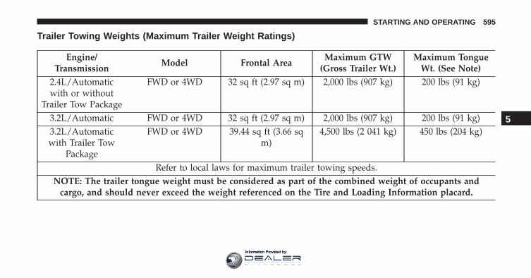
Trailer Towing Weights (Maximum Trailer Weight Ratings)
Engine/Transmission
Model Frontal AreaMaximum GTW
(Gross Trailer Wt.)Maximum Tongue
Wt. (See Note)2.4L/Automaticwith or without
Trailer Tow Package
FWD or 4WD 32 sq ft (2.97 sq m) 2,000 lbs (907 kg) 200 lbs (91 kg)
3.2L/Automatic FWD or 4WD 32 sq ft (2.97 sq m) 2,000 lbs (907 kg) 200 lbs (91 kg)3.2L/Automaticwith Trailer Tow
Package
FWD or 4WD 39.44 sq ft (3.66 sqm)
4,500 lbs (2 041 kg) 450 lbs (204 kg)
Refer to local laws for maximum trailer towing speeds.NOTE: The trailer tongue weight must be considered as part of the combined weight of occupants and
cargo, and should never exceed the weight referenced on the Tire and Loading Information placard.
5
STARTING AND OPERATING 595
Information Provided by:
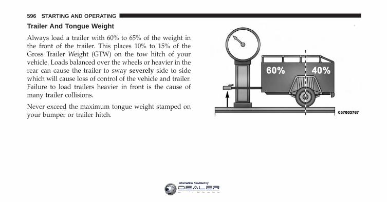
Trailer And Tongue Weight
Always load a trailer with 60% to 65% of the weight inthe front of the trailer. This places 10% to 15% of theGross Trailer Weight (GTW) on the tow hitch of yourvehicle. Loads balanced over the wheels or heavier in therear can cause the trailer to sway severely side to sidewhich will cause loss of control of the vehicle and trailer.Failure to load trailers heavier in front is the cause ofmany trailer collisions.
Never exceed the maximum tongue weight stamped onyour bumper or trailer hitch.
596 STARTING AND OPERATING
Information Provided by:
Consider the following items when computing theweight on the rear axle of the vehicle:
• The tongue weight of the trailer.
• The weight of any other type of cargo or equipmentput in or on your vehicle.
• The weight of the driver and all passengers.
NOTE: Remember that everything put into or on thetrailer adds to the load on your vehicle. Also, additionalfactory-installed options or dealer-installed options mustbe considered as part of the total load on your vehicle.Refer to the “Tire And Loading Information” placard forthe maximum combined weight of occupants and cargofor your vehicle.
Towing Requirements
To promote proper break-in of your new vehicle drive-train components, the following guidelines are recom-mended:
WARNING!
Improper towing can lead to a collision. Follow theseguidelines to make your trailer towing as safe aspossible:• Make certain that the load is secured in the trailer
and that it will not shift during travel. Whentrailering cargo that is not fully secured, dynamicload shifts can occur that may be difficult for thedriver to control. You could lose control of yourvehicle and have a collision.
• When hauling cargo, or towing a trailer, do notoverload your vehicle or trailer. Overloading can
(Continued)
5
STARTING AND OPERATING 597
Information Provided by:
WARNING! (Continued)cause a loss of control, poor performance, or dam-age to brakes, axle, engine, transmission, steering,suspension, chassis structure, or tires.
• Safety chains must always be used between yourvehicle and trailer. Always connect the chains tothe frame or hook retainers of the vehicle hitch.Cross the chains under the trailer tongue and allowenough slack for turning corners.
• Vehicles with trailers should not be parked on agrade. When parking, apply the parking brake onthe tow vehicle. Put the tow vehicle transmission inPARK. Always, block or �chock� the trailer wheels.
• GCWR must not be exceeded.
(Continued)
WARNING! (Continued)• Total weight must be distributed between the tow
vehicle and the trailer such that the following fourratings are not exceeded:
1. GVWR
2. GTW
3. GAWR
4. Tongue weight rating for the trailer hitch uti-lized.
598 STARTING AND OPERATING
Information Provided by:
CAUTION!
• Do not tow a trailer at all during the first 500 miles(805 km) the new vehicle is driven. The engine, axleor other parts could be damaged.
• Then, during the first 500 miles (805 km) that atrailer is towed, do not drive over 50 mph (80 km/h)and do not make starts at full throttle. This helpsthe engine and other parts of the vehicle wear in atthe heavier loads.
Towing Requirements — Tires
• Do not attempt to tow a trailer while using a compactspare tire.
• Proper tire inflation pressures are essential to the safeand satisfactory operation of your vehicle. Refer to“Tires – General Information” in “Starting And Oper-ating” for proper tire inflation procedures.
• Check the trailer tires for proper tire inflation pres-sures before trailer usage.
• Check for signs of tire wear or visible tire damagebefore towing a trailer. Refer to “Tires – GeneralInformation” in “Starting And Operating” for theproper inspection procedure.
• When replacing tires, refer to “Tires – General Infor-mation” in “Starting And Operating” for the propertire replacement procedures. Replacing tires with ahigher load carrying capacity will not increase thevehicle’s GVWR and GAWR limits.
Towing Requirements — Trailer Brakes
• Do not interconnect the hydraulic brake system orvacuum system of your vehicle with that of the trailer.This could cause inadequate braking and possiblepersonal injury.
5
STARTING AND OPERATING 599
Information Provided by:
• An electronically actuated trailer brake controller isrequired when towing a trailer with electronicallyactuated brakes. When towing a trailer equipped witha hydraulic surge actuated brake system, an electronicbrake controller is not required.
• Trailer brakes are recommended for trailers over1,000 lbs (454 kg) and required for trailers in excess of2,000 lbs (907 kg).
WARNING!
• Do not connect trailer brakes to your vehicle’shydraulic brake lines. It can overload your brakesystem and cause it to fail. You might not havebrakes when you need them and could have acollision.
(Continued)
WARNING! (Continued)• Towing any trailer will increase your stopping
distance. When towing you should allow for addi-tional space between your vehicle and the vehiclein front of you. Failure to do so could result in acollision.
CAUTION!
If the trailer weighs more than 1,000 lbs (454 kg)loaded, it should have its own brakes and theyshould be of adequate capacity. Failure to do thiscould lead to accelerated brake lining wear, higherbrake pedal effort, and longer stopping distances.
600 STARTING AND OPERATING
Information Provided by:
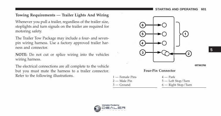
Towing Requirements — Trailer Lights And Wiring
Whenever you pull a trailer, regardless of the trailer size,stoplights and turn signals on the trailer are required formotoring safety.
The Trailer Tow Package may include a four- and seven-pin wiring harness. Use a factory approved trailer har-ness and connector.
NOTE: Do not cut or splice wiring into the vehicleswiring harness.
The electrical connections are all complete to the vehiclebut you must mate the harness to a trailer connector.Refer to the following illustrations.
Four-Pin Connector
1 — Female Pins2 — Male Pin3 — Ground
4 — Park5 — Left Stop/Turn6 — Right Stop/Turn
5
STARTING AND OPERATING 601
Information Provided by:
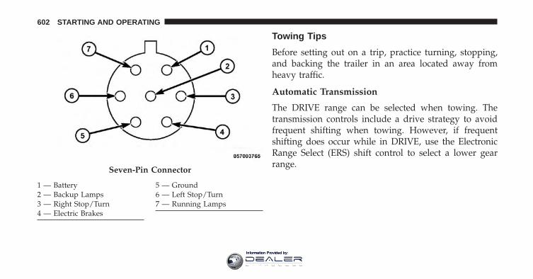
Towing Tips
Before setting out on a trip, practice turning, stopping,and backing the trailer in an area located away fromheavy traffic.
Automatic Transmission
The DRIVE range can be selected when towing. Thetransmission controls include a drive strategy to avoidfrequent shifting when towing. However, if frequentshifting does occur while in DRIVE, use the ElectronicRange Select (ERS) shift control to select a lower gearrange.
Seven-Pin Connector
1 — Battery2 — Backup Lamps3 — Right Stop/Turn4 — Electric Brakes
5 — Ground6 — Left Stop/Turn7 — Running Lamps
602 STARTING AND OPERATING
Information Provided by:
NOTE: Using a lower gear range while operating thevehicle under heavy loading conditions will improveperformance and extend transmission life by reducingexcessive shifting and heat build up. This action will alsoprovide better engine braking.
Electronic Speed Control — If Equipped
• Do not use in hilly terrain or with heavy loads.
• When using the speed control, if you experience speeddrops greater than 10 mph (16 km/h), disengage untilyou can get back to cruising speed.
• Use speed control in flat terrain and with light loads tomaximize fuel efficiency.
Cooling System
To reduce potential for engine and transmission over-heating, take the following actions:
City Driving
When stopped for short periods of time, shift the trans-mission into NEUTRAL and increase engine idle speed.
Highway Driving
Reduce speed.
Air Conditioning
Turn off temporarily.
5
STARTING AND OPERATING 603
Information Provided by:
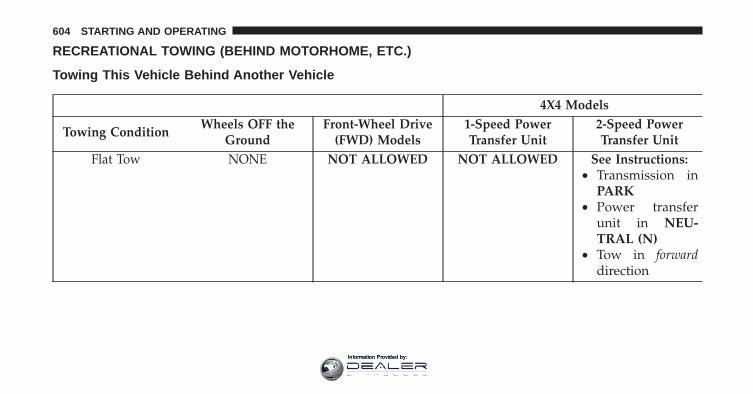
RECREATIONAL TOWING (BEHIND MOTORHOME, ETC.)
Towing This Vehicle Behind Another Vehicle
4X4 Models
Towing ConditionWheels OFF the
GroundFront-Wheel Drive
(FWD) Models1-Speed PowerTransfer Unit
2-Speed PowerTransfer Unit
Flat Tow NONE NOT ALLOWED NOT ALLOWED See Instructions:• Transmission in
PARK• Power transfer
unit in NEU-TRAL (N)
• Tow in forwarddirection
604 STARTING AND OPERATING
Information Provided by:
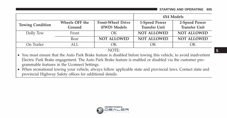
4X4 Models
Towing ConditionWheels OFF the
GroundFront-Wheel Drive
(FWD) Models1-Speed PowerTransfer Unit
2-Speed PowerTransfer Unit
Dolly Tow Front OK NOT ALLOWED NOT ALLOWEDRear NOT ALLOWED NOT ALLOWED NOT ALLOWED
On Trailer ALL OK OK OKNOTE:
• You must ensure that the Auto Park Brake feature is disabled before towing this vehicle, to avoid inadvertentElectric Park Brake engagement. The Auto Park Brake feature is enabled or disabled via the customer pro-grammable features in the Uconnect Settings.
• When recreational towing your vehicle, always follow applicable state and provincial laws. Contact state andprovincial Highway Safety offices for additional details.
5
STARTING AND OPERATING 605
Information Provided by:
Recreational Towing — Front-Wheel Drive (FWD)Models
DO NOT flat tow this vehicle. Damage to the drivetrainwill result.
Recreational towing (for front-wheel drive models) isallowed ONLY if the front wheels are OFF the ground.This may be accomplished using a tow dolly or vehicletrailer. If using a tow dolly, follow this procedure:
1. Properly secure the dolly to the tow vehicle, followingthe dolly manufacturer’s instructions.
2. Drive the front wheels onto the tow dolly.
3. Apply the parking brake. Place the transmission inPARK. Turn the engine OFF.
4. Properly secure the front wheels to the dolly, followingthe dolly manufacturer’s instructions.
5. Turn the ignition to the ON/RUN position, but do notstart the engine.
6. Press and hold the brake pedal.
7. Release the parking brake.
8. Turn the ignition OFF, remove the Key Fob, andrelease the brake pedal.
CAUTION!
• Towing with the front wheels on the ground willcause severe transmission damage. Damage fromimproper towing is not covered under the NewVehicle Limited Warranty.
• Ensure that the Electric Park Brake is released, andremains released, while being towed.
606 STARTING AND OPERATING
Information Provided by:
Recreational Towing — 4X4 Models With 1-SpeedPower Transfer Unit
Recreational towing is not allowed. These models donot have a NEUTRAL (N) position in the power transferunit.
NOTE: This vehicle may be towed on a flatbed or vehicletrailer provided all four wheels are OFF the ground.
CAUTION!
Towing this vehicle with ANY of its wheels on theground can cause severe transmission and/or powertransfer unit damage. Damage from improper tow-ing is not covered under the New Vehicle LimitedWarranty.
Recreational Towing — 4X4 Models With 2-SpeedPower Transfer Unit
The power transfer unit must be shifted into NEUTRAL(N) and the transmission must be in PARK for recre-ational towing. The NEUTRAL (N) selection button isadjacent to the 4WD selector switch. Shifts into and out ofNEUTRAL (N) can take place with the selector switch inany mode position.
CAUTION!
• DO NOT dolly tow any 4x4 vehicle. Towing withonly one set of wheels on the ground (front or rear)will cause severe transmission and/or power trans-fer unit damage. Tow with all four wheels eitherON the ground, or OFF the ground (using a vehicletrailer).
(Continued)
5
STARTING AND OPERATING 607
Information Provided by:
CAUTION! (Continued)• Tow only in a forward direction. Towing this ve-
hicle backwards can cause severe damage to thepower transfer unit.
• The transmission must be in PARK for recreationaltowing.
• Before recreational towing, perform the procedureoutlined under “Shifting into NEUTRAL (N)” to becertain that the power transfer unit is fully inNEUTRAL (N). Otherwise, internal damage willresult.
• Towing this vehicle in violation of the above re-quirements can cause severe transmission and/orpower transfer unit damage. Damage from im-proper towing is not covered under the New Ve-hicle Limited Warranty.
(Continued)
CAUTION! (Continued)• Ensure that the Electric Park Brake is released, and
remains released, while being towed.• Do not use a bumper-mounted clamp-on tow bar
on your vehicle. The bumper face bar will bedamaged.
608 STARTING AND OPERATING
Information Provided by:
Shifting Into NEUTRAL (N)
WARNING!
You or others could be injured or killed if you leavethe vehicle unattended with the power transfer unitin the NEUTRAL (N) position without first fullyengaging the parking brake. The NEUTRAL (N)position disengages both the front and rear drive-shafts from the powertrain and will allow the vehicleto roll, even if the automatic transmission is in PARK(or manual transmission is in gear). The parkingbrake should always be applied when the driver isnot in the vehicle.
Use the following procedure to prepare your vehicle forrecreational towing.
CAUTION!
It is necessary to follow these steps to be certain thatthe power transfer unit is fully in NEUTRAL (N)before recreational towing to prevent damage tointernal parts.
1. Bring the vehicle to a complete stop and shift thetransmission to PARK.
2. Turn the engine OFF.
3. Turn the ignition switch to the ON/RUN position, butdo not start the engine.
5
STARTING AND OPERATING 609
Information Provided by:

4. Press and hold the brake pedal.
5. Shift the transmission into NEUTRAL.
6. Using a ballpoint pen or similar object, push and holdthe recessed NEUTRAL (N) button (located by theselector switch) for four seconds. The light behind theNEUTRAL (N) symbol will blink, indicating shift inprogress. The light will stop blinking (stay on solid)when the shift to NEUTRAL (N) is complete.
7. After the shift is completed and the NEUTRAL (N)light stays on, release the NEUTRAL (N) button.
8. Start the engine.
9. Release the parking brake.
10. Shift the transmission into REVERSE.
Neutral Switch
610 STARTING AND OPERATING
Information Provided by:
11. Release the brake pedal for five seconds and ensurethat there is no vehicle movement.
12. Shift the transmission to NEUTRAL.
13. Apply the parking brake.
14. Shift the transmission into PARK, turn the engineOFF, and remove the key fob.
15. Attach the vehicle to the tow vehicle using a suitabletow bar.
16. Turn the ignition to the ON/RUN position, but donot start the engine.
17. Press and hold the brake pedal.
18. Release the parking brake.
19. Turn the ignition OFF, remove the Key Fob, andrelease the brake pedal.
NOTE:
• Steps 1 through 5 are requirements that must be metbefore pushing the NEUTRAL (N) button, and mustcontinue to be met until the shift has been completed.If any of these requirements are not met before push-ing the NEUTRAL (N) button or are no longer metduring the shift, then the NEUTRAL (N) indicator lightwill flash continuously until all requirements are metor until the NEUTRAL (N) button is released.
• The ignition switch must be in the ON/RUN positionfor a shift to take place and for the position indicatorlights to be operable. If the ignition switch is not in theON/RUN position, the shift will not take place and noposition indicator lights will be on or flashing.
• A flashing NEUTRAL (N) position indicator lightindicates that shift requirements have not been met.
5
STARTING AND OPERATING 611
Information Provided by:
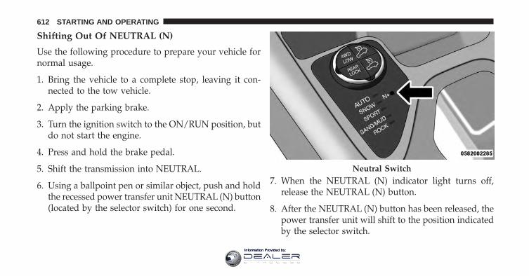
Shifting Out Of NEUTRAL (N)
Use the following procedure to prepare your vehicle fornormal usage.
1. Bring the vehicle to a complete stop, leaving it con-nected to the tow vehicle.
2. Apply the parking brake.
3. Turn the ignition switch to the ON/RUN position, butdo not start the engine.
4. Press and hold the brake pedal.
5. Shift the transmission into NEUTRAL.
6. Using a ballpoint pen or similar object, push and holdthe recessed power transfer unit NEUTRAL (N) button(located by the selector switch) for one second.
7. When the NEUTRAL (N) indicator light turns off,release the NEUTRAL (N) button.
8. After the NEUTRAL (N) button has been released, thepower transfer unit will shift to the position indicatedby the selector switch.
Neutral Switch
612 STARTING AND OPERATING
Information Provided by:
NOTE: When shifting the power transfer unit out ofNEUTRAL (N), the engine should remain OFF to avoidgear clash.
9. Shift the transmission into PARK.
10. Release the brake pedal.
11. Disconnect vehicle from the tow vehicle.
12. Start the engine.
13. Press and hold the brake pedal.
14. Release the parking brake.
15. Shift the transmission into DRIVE, release the brakepedal, and check that the vehicle operates normally.
16. Re-enable the Auto Park Brake feature, if desired.
NOTE:
• Steps 1 through 5 are requirements that must be metbefore pushing the NEUTRAL (N) button, and mustcontinue to be met until the shift has been completed.If any of these requirements are not met before push-ing the NEUTRAL (N) button or are no longer metduring the shift, the NEUTRAL (N) indicator light willflash continuously until all requirements are met oruntil the NEUTRAL (N) button is released.
• The ignition switch must be in the ON/RUN positionfor a shift to take place and for the position indicatorlights to be operable. If the ignition switch is not in theON/RUN position, the shift will not take place and noposition indicator lights will be on or flashing.
• A flashing NEUTRAL (N) position indicator lightindicates that shift requirements have not been met.
5
STARTING AND OPERATING 613
Information Provided by:

Information Provided by:
WHAT TO DO IN EMERGENCIES
CONTENTS� HAZARD WARNING FLASHERS . . . . . . . . . . .617
� IF YOUR ENGINE OVERHEATS . . . . . . . . . . . .617
� WHEEL AND TIRE TORQUESPECIFICATIONS . . . . . . . . . . . . . . . . . . . . . .618
▫ Torque Specifications . . . . . . . . . . . . . . . . . .619
� TIRE SERVICE KIT — IF EQUIPPED . . . . . . . . .620
▫ Tire Service Kit Storage . . . . . . . . . . . . . . . . .621
▫ Tire Service Kit Components And Operation . .621
▫ Tire Service Kit Usage Precautions . . . . . . . . .622
▫ Sealing A Tire With Tire Service Kit . . . . . . . .625
� JACKING AND TIRE CHANGING . . . . . . . . . .631
▫ Jack Location/Spare Tire Stowage . . . . . . . . .632
▫ Preparations For Jacking . . . . . . . . . . . . . . . .634
▫ Jacking Instructions . . . . . . . . . . . . . . . . . . .635
▫ Road Tire Installation . . . . . . . . . . . . . . . . . . .643
� JUMP-STARTING PROCEDURES . . . . . . . . . . .644
▫ Preparations For Jump-Start . . . . . . . . . . . . . .645
▫ Jump Starting Procedure . . . . . . . . . . . . . . . .646
� FREEING A STUCK VEHICLE . . . . . . . . . . . . .648
� RECOVERY STRAP — IF EQUIPPED . . . . . . . . .650
6
Information Provided by:
� SHIFT LEVER OVERRIDE . . . . . . . . . . . . . . . .651
� TOWING A DISABLED VEHICLE . . . . . . . . . . .652
▫ Front-Wheel Drive (FWD) Models . . . . . . . . . .654
▫ 4x4 Models With 1–Speed Power TransferUnit . . . . . . . . . . . . . . . . . . . . . . . . . . . . . . .655
▫ 4x4 Models With 2–Speed Power TransferUnit . . . . . . . . . . . . . . . . . . . . . . . . . . . . . . .656
616 WHAT TO DO IN EMERGENCIES
Information Provided by:
HAZARD WARNING FLASHERS
The Hazard Warning flasher switch is located in theswitch bank below the radio screen.
Push the switch to turn on the Hazard Warningflasher. When the switch is activated, all direc-
tional turn signals will flash on and off to warn oncomingtraffic of an emergency. Push the switch a second time toturn off the Hazard Warning flashers.
This is an emergency warning system and it should notbe used when the vehicle is in motion. Use it when yourvehicle is disabled and it is creating a safety hazard forother motorists.
When you must leave the vehicle to seek assistance, theHazard Warning flashers will continue to operate eventhough the ignition is placed in the OFF position.
NOTE: With extended use the Hazard Warning flashersmay wear down your battery.
IF YOUR ENGINE OVERHEATS
In any of the following situations, you can reduce thepotential for overheating your engine by taking theappropriate action.
• On the highways — slow down.
• In city traffic — while stopped, put transmission inNEUTRAL, but do not increase engine idle speed.
CAUTION!
Driving with a hot cooling system could damageyour vehicle. If the temperature gauge reads “H,”pull over and stop the vehicle. Idle the vehicle withthe air conditioner turned off until the pointer dropsback into the normal range. If the pointer remains onthe “H” and you hear continuous chimes, turn theengine off immediately and call for service.
6
WHAT TO DO IN EMERGENCIES 617
Information Provided by:
NOTE: There are steps that you can take to slow downan impending overheat condition:
• If your air conditioner (A/C) is on, turn it off. The A/Csystem adds heat to the engine cooling system andturning the A/C off can help remove this heat.
• You can also turn the temperature control to maximumheat, the mode control to floor and the blower controlto high. This allows the heater core to act as asupplement to the radiator and aids in removing heatfrom the engine cooling system.
WARNING!
You or others can be badly burned by hot enginecoolant (antifreeze) or steam from your radiator. Ifyou see or hear steam coming from under the hood,do not open the hood until the radiator has had timeto cool. Never try to open a cooling system pressurecap when the radiator or coolant bottle is hot.
WHEEL AND TIRE TORQUE SPECIFICATIONS
Proper lug nut/bolt torque is very important to ensurethat the wheel is properly mounted to the vehicle. Anytime a wheel has been removed and reinstalled on thevehicle the lug nuts/bolts should be torqued using aproperly calibrated torque wrench.
618 WHAT TO DO IN EMERGENCIES
Information Provided by:
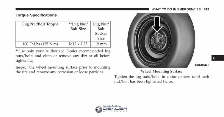
Torque Specifications
Lug Nut/Bolt Torque **Lug Nut/Bolt Size
Lug Nut/Bolt
SocketSize
100 Ft-Lbs (135 N·m) M12 x 1.25 19 mm
**Use only your Authorized Dealer recommended lugnuts/bolts and clean or remove any dirt or oil beforetightening.
Inspect the wheel mounting surface prior to mountingthe tire and remove any corrosion or loose particles.
Tighten the lug nuts/bolts in a star pattern until eachnut/bolt has been tightened twice.
Wheel Mounting Surface
6
WHAT TO DO IN EMERGENCIES 619
Information Provided by:
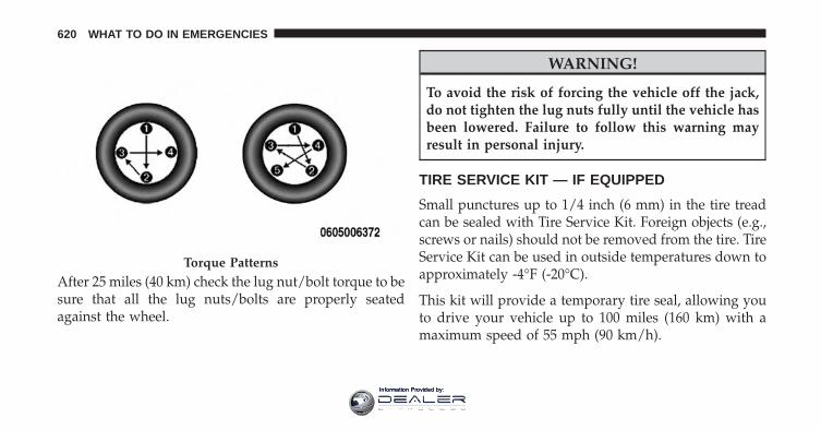
After 25 miles (40 km) check the lug nut/bolt torque to besure that all the lug nuts/bolts are properly seatedagainst the wheel.
WARNING!
To avoid the risk of forcing the vehicle off the jack,do not tighten the lug nuts fully until the vehicle hasbeen lowered. Failure to follow this warning mayresult in personal injury.
TIRE SERVICE KIT — IF EQUIPPED
Small punctures up to 1/4 inch (6 mm) in the tire treadcan be sealed with Tire Service Kit. Foreign objects (e.g.,screws or nails) should not be removed from the tire. TireService Kit can be used in outside temperatures down toapproximately -4°F (-20°C).
This kit will provide a temporary tire seal, allowing youto drive your vehicle up to 100 miles (160 km) with amaximum speed of 55 mph (90 km/h).
Torque Patterns
620 WHAT TO DO IN EMERGENCIES
Information Provided by:
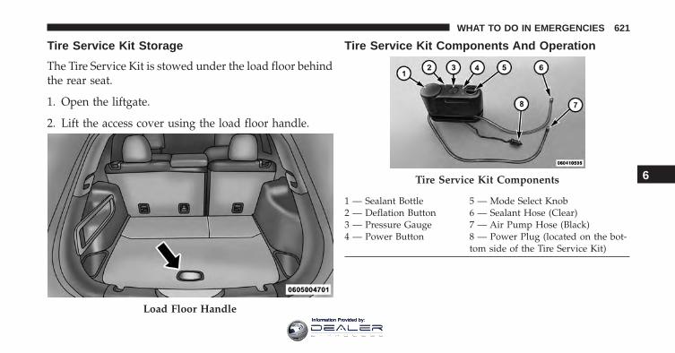
Tire Service Kit Storage
The Tire Service Kit is stowed under the load floor behindthe rear seat.
1. Open the liftgate.
2. Lift the access cover using the load floor handle.
Tire Service Kit Components And Operation
Load Floor Handle
Tire Service Kit Components
1 — Sealant Bottle 5 — Mode Select Knob2 — Deflation Button 6 — Sealant Hose (Clear)3 — Pressure Gauge 7 — Air Pump Hose (Black)4 — Power Button 8 — Power Plug (located on the bot-
tom side of the Tire Service Kit)
6
WHAT TO DO IN EMERGENCIES 621
Information Provided by:
Using The Mode Select Knob And Hoses
Your Tire Service Kit is equipped with the followingsymbols to indicate the air or sealant mode.
Selecting Air Mode
Push in the Mode Select Knob (5) and turn to thisposition for air pump operation only. Use the
Black Air Pump Hose (7) when selecting this mode.
Selecting Sealant Mode
Push in the Mode Select Knob (5) and turn to thisposition to inject the Tire Service Kit Sealant and
to inflate the tire. Use the Sealant Hose (clear hose) (6)when selecting this mode.
Using The Power Button
Push and release the Power Button (4) once toturn On the Tire Service Kit. Push and release the PowerButton (4) again to turn Off the Tire Service Kit.
Using The Deflation Button
Push the Deflation Button (2) to reduce the airpressure in the tire if it becomes over-inflated.
Tire Service Kit Usage Precautions
• Replace the Tire Service Kit Sealant Bottle (1) andSealant Hose (6) prior to the expiration date (printed atthe lower right hand corner on the bottle label) toassure optimum operation of the system. Refer to“Sealing a Tire with Tire Service Kit” section (F)“Sealant Bottle and Hose Replacement”.
622 WHAT TO DO IN EMERGENCIES
Information Provided by:
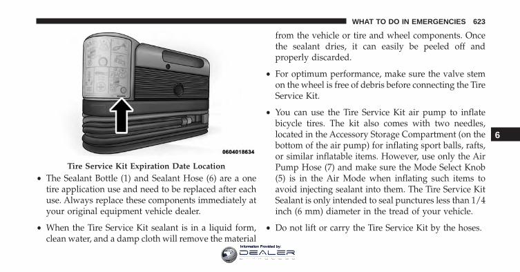
• The Sealant Bottle (1) and Sealant Hose (6) are a onetire application use and need to be replaced after eachuse. Always replace these components immediately atyour original equipment vehicle dealer.
• When the Tire Service Kit sealant is in a liquid form,clean water, and a damp cloth will remove the material
from the vehicle or tire and wheel components. Oncethe sealant dries, it can easily be peeled off andproperly discarded.
• For optimum performance, make sure the valve stemon the wheel is free of debris before connecting the TireService Kit.
• You can use the Tire Service Kit air pump to inflatebicycle tires. The kit also comes with two needles,located in the Accessory Storage Compartment (on thebottom of the air pump) for inflating sport balls, rafts,or similar inflatable items. However, use only the AirPump Hose (7) and make sure the Mode Select Knob(5) is in the Air Mode when inflating such items toavoid injecting sealant into them. The Tire Service KitSealant is only intended to seal punctures less than 1/4inch (6 mm) diameter in the tread of your vehicle.
• Do not lift or carry the Tire Service Kit by the hoses.
Tire Service Kit Expiration Date Location
6
WHAT TO DO IN EMERGENCIES 623
Information Provided by:
WARNING!
• Do not attempt to seal a tire on the side of thevehicle closest to traffic. Pull far enough off theroad to avoid the danger of being hit when usingthe Tire Service Kit.
• Do not use Tire Service Kit or drive the vehicleunder the following circumstances:– If the puncture in the tire tread is approximately
1/4 inch (6 mm) or larger.– If the tire has any sidewall damage.– If the tire has any damage from driving with
extremely low tire pressure.– If the tire has any damage from driving on a flat
tire.– If the wheel has any damage.– If you are unsure of the condition of the tire or
the wheel.
(Continued)
WARNING! (Continued)• Keep Tire Service Kit away from open flames or
heat source.• A loose Tire Service Kit thrown forward in a
collision or hard stop could endanger the occupantsof the vehicle. Always stow the Tire Service Kit inthe place provided. Failure to follow these warn-ings can result in injuries that are serious or fatal toyou, your passengers, and others around you.
• Take care not to allow the contents of Tire ServiceKit to come in contact with hair, eyes, or clothing.Tire Service Kit sealant is harmful if inhaled,swallowed, or absorbed through the skin. It causesskin, eye, and respiratory irritation. Flush immedi-ately with plenty of water if there is any contactwith eyes or skin. Change clothing as soon aspossible, if there is any contact with clothing.
(Continued)
624 WHAT TO DO IN EMERGENCIES
Information Provided by:
WARNING! (Continued)• Tire Service Kit Sealant solution contains latex. In
case of an allergic reaction or rash, consult a phy-sician immediately. Keep Tire Service Kit out ofreach of children. If swallowed, rinse mouth imme-diately with plenty of water and drink plenty ofwater. Do not induce vomiting! Consult a physicianimmediately.
Sealing A Tire With Tire Service Kit
(A) Whenever You Stop To Use Tire Service Kit:
1. Pull over to a safe location and turn on the vehicle’sHazard Warning flashers.
2. Verify that the valve stem (on the wheel with thedeflated tire) is in a position that is near to the ground.This will allow the Tire Service Kit Hoses (6) and (7) toreach the valve stem and keep the Tire Service Kit flat
on the ground. This will provide the best positioningof the kit when injecting the sealant into the deflatedtire and running the air pump. Move the vehicle asnecessary to place the valve stem in this positionbefore proceeding.
3. Place the transmission in PARK (auto transmission) orin Gear (manual transmission) and place the ignitionin the OFF position.
4. Set the parking brake.
(B) Setting Up To Use Tire Service Kit:
1. Push in the Mode Select Knob (5) and turn to theSealant Mode position.
2. Uncoil the Sealant Hose (6) and then remove the capfrom the fitting at the end of the hose.
3. Place the Tire Service Kit flat on the ground next to thedeflated tire.
6
WHAT TO DO IN EMERGENCIES 625
Information Provided by:
4. Remove the cap from the valve stem and then screwthe fitting at the end of the Sealant Hose (6) onto thevalve stem.
5. Uncoil the Power Plug (8) and insert the plug into thevehicle’s 12 Volt power outlet.
NOTE: Do not remove foreign objects (e.g., screws ornails) from the tire.
(C) Injecting Tire Service Kit Sealant Into TheDeflated Tire:
• Always start the engine before turning ON the TireService Kit.
NOTE: Manual transmission vehicles must have theparking brake engaged and the shift lever in NEUTRAL.
• After pushing the Power Button (4), the sealant (whitefluid) will flow from the Sealant Bottle (1) through theSealant Hose (6) and into the tire.
NOTE: Sealant may leak out through the puncture in thetire.
If the sealant (white fluid) does not flow within 0 – 10seconds through the Sealant Hose (6):
1. Push the Power Button (4) to turn Off the Tire ServiceKit. Disconnect the Sealant Hose (6) from the valvestem. Make sure the valve stem is free of debris.Reconnect the Sealant Hose (6) to the valve stem.Check that the Mode Select Knob (5) is in the SealantMode position and not Air Mode. Push the PowerButton (4) to turn On the Tire Service Kit.
2. Connect the Power Plug (8) to a different 12 Voltpower outlet in your vehicle or another vehicle, ifavailable. Make sure the engine is running beforeturning ON the Tire Service Kit.
3. The Sealant Bottle (1) may be empty due to previoususe. Call for assistance.
626 WHAT TO DO IN EMERGENCIES
Information Provided by:
NOTE: If the Mode Select Knob (5) is on Air Mode andthe pump is operating, air will dispense from the AirPump Hose (7) only, not the Sealant Hose (6).
If the sealant (white fluid) does flow through theSealant Hose (6):
1. Continue to operate the pump until sealant is nolonger flowing through hose (typically takes 30 - 70seconds). As the sealant flows through the SealantHose (6), the Pressure Gauge (3) can read as high as 70psi (4.8 Bar). The Pressure Gauge (3) will decreasequickly from approximately 70 psi (4.8 Bar) to theactual tire pressure when the Sealant Bottle (1) isempty.
2. The pump will start to inject air into the tire immedi-ately after the Sealant Bottle (1) is empty. Continue tooperate the pump and inflate the tire to the pressureindicated on the tire pressure label on the driver-side
latch pillar (recommended pressure). Check the tirepressure by looking at the Pressure Gauge (3).
If the tire does not inflate to at least 26 psi (1.8 Bar)pressure within 15 minutes:
• The tire is too badly damaged. Do not attempt to drivethe vehicle further. Call for assistance.
NOTE: If the tire becomes over-inflated, push the Defla-tion Button to reduce the tire pressure to the recom-mended inflation pressure before continuing.
If the tire inflates to the recommended pressure or is atleast 26 psi (1.8 Bar) pressure within 15 minutes:
1. Push the Power Button (4) to turn off the Tire ServiceKit.
2. Remove the Speed Limit sticker from the top of theSealant Bottle (1) and place the sticker on the instru-ment panel.
6
WHAT TO DO IN EMERGENCIES 627
Information Provided by:
3. Immediately disconnect the Sealant Hose (6) from thevalve stem, reinstall the cap on the fitting at the end ofthe hose, and place the Tire Service Kit in the vehiclestorage location. Quickly proceed to (D) “Drive Ve-hicle.”
CAUTION!
• The metal end fitting from Power Plug (8) may gethot after use, so it should be handled carefully.
• Failure to reinstall the cap on the fitting at the endof the Sealant Hose (6) can result in sealant con-tacting your skin, clothing, and the vehicle’s inte-rior. It can also result in sealant contacting internalTire Service Kit components which may causepermanent damage to the kit.
(D) Drive Vehicle:
Immediately after injecting sealant and inflating the tire,drive the vehicle 5 miles (8 km) or 10 minutes to ensuredistribution of the Tire Service Kit Sealant within the tire.Do not exceed 55 mph (90 km/h).
WARNING!
Tire Service Kit is not a permanent flat tire repair.Have the tire inspected and repaired or replaced afterusing Tire Service Kit. Do not exceed 55 mph (90km/h) until the tire is repaired or replaced. Failure tofollow this warning can result in injuries that areserious or fatal to you, your passengers, and othersaround you.
628 WHAT TO DO IN EMERGENCIES
Information Provided by:
(E) After Driving:
Pull over to a safe location. Refer to “Whenever You Stopto Use Tire Service Kit” before continuing.
1. Push in the Mode Select Knob (5) and turn to the AirMode position.
2. Uncoil the power plug and insert the plug into thevehicle’s 12 Volt power outlet.
3. Uncoil the Air Pump Hose (7) (black in color) andscrew the fitting at the end of hose (7) onto the valvestem.
4. Check the pressure in the tire by reading the PressureGauge (3).
If tire pressure is less than 19 psi (1.3 Bar):
The tire is too badly damaged. Do not attempt to drivethe vehicle further. Call for assistance.
If the tire pressure is 19 psi (1.3 Bar) or higher:
1. Push the Power Button (4) to turn on Tire Service Kitand inflate the tire to the pressure indicated on the tireand loading information label on the driver-side dooropening.
NOTE: If the tire becomes over-inflated, push the Defla-tion Button to reduce the tire pressure to the recom-mended inflation pressure before continuing.
6
WHAT TO DO IN EMERGENCIES 629
Information Provided by:
2. Disconnect the Tire Service Kit from the valve stem,reinstall the cap on the valve stem and unplug from 12Volt outlet.
3. Place the Tire Service Kit in its proper storage area inthe vehicle.
4. Have the tire inspected and repaired or replaced at theearliest opportunity at an authorized dealer or tireservice center.
5. Remove the Speed Limit sticker from the instrumentpanel after the tire has been repaired.
6. Replace the Sealant Bottle (1) and Sealant Hose (6)assembly at your authorized dealer as soon as pos-sible. Refer to (F) “Sealant Bottle and Hose Replace-ment”.
NOTE: When having the tire serviced, advise the autho-rized dealer or service center that the tire has been sealedusing the Tire Service Kit.
(F) Sealant Bottle And Hose Replacement:
1. Uncoil the Sealant Hose (6) (clear in color).
2. Locate the round Sealant Bottle release button in therecessed area under the sealant bottle.
3. Push the Sealant Bottle release button. The SealantBottle (1) will pop up. Remove the bottle and disposeof it accordingly.
4. Clean any remaining sealant from the Tire Service Kithousing.
630 WHAT TO DO IN EMERGENCIES
Information Provided by:
5. Position the new Sealant Bottle (1) in the housing sothat the Sealant Hose (6) aligns with the hose slot inthe front of the housing. Push the bottle into thehousing. An audible click will be heard indicating thebottle is locked into place.
6. Verify that the cap is installed on the fitting at the endof the Sealant Hose (6) and return the hose to itsstorage area (located on the bottom of the air pump).
7. Return the Tire Service Kit to its storage location in thevehicle.
JACKING AND TIRE CHANGING
WARNING!
• Do not attempt to change a tire on the side of thevehicle close to moving traffic. Pull far enough offthe road to avoid the danger of being hit whenoperating the jack or changing the wheel.
• Being under a jacked-up vehicle is dangerous. Thevehicle could slip off the jack and fall on you. Youcould be crushed. Never put any part of your bodyunder a vehicle that is on a jack. If you need to getunder a raised vehicle, take it to a service centerwhere it can be raised on a lift.
• Never start or run the engine while the vehicle ison a jack.
(Continued)
6
WHAT TO DO IN EMERGENCIES 631
Information Provided by:
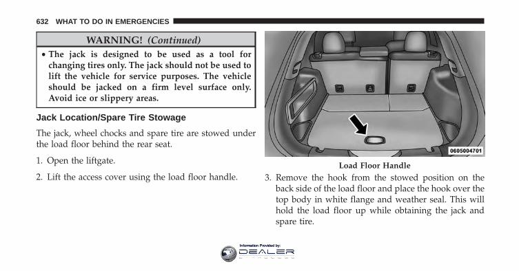
WARNING! (Continued)• The jack is designed to be used as a tool for
changing tires only. The jack should not be used tolift the vehicle for service purposes. The vehicleshould be jacked on a firm level surface only.Avoid ice or slippery areas.
Jack Location/Spare Tire Stowage
The jack, wheel chocks and spare tire are stowed underthe load floor behind the rear seat.
1. Open the liftgate.
2. Lift the access cover using the load floor handle. 3. Remove the hook from the stowed position on theback side of the load floor and place the hook over thetop body in white flange and weather seal. This willhold the load floor up while obtaining the jack andspare tire.
Load Floor Handle
632 WHAT TO DO IN EMERGENCIES
Information Provided by:
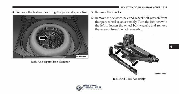
4. Remove the fastener securing the jack and spare tire. 5. Remove the chocks.
6. Remove the scissors jack and wheel bolt wrench fromthe spare wheel as an assembly. Turn the jack screw tothe left to loosen the wheel bolt wrench, and removethe wrench from the jack assembly.
Jack And Spare Tire Fastener
Jack And Tool Assembly
6
WHAT TO DO IN EMERGENCIES 633
Information Provided by:
NOTE: The jack handle attaches to the side of the jackwith two attachment points. When the jack is partiallyexpanded, the tension between the two attachmentpoints holds the jack handle in place.
7. Remove the spare tire.
WARNING!
A loose tire or jack thrown forward in a collision orhard stop could endanger the occupants of the ve-hicle. Always stow the jack parts and the spare tire inthe places provided. Have the deflated (flat) tirerepaired or replaced immediately.
Preparations For Jacking
1. Park the vehicle on a firm level surface as far from theedge of the roadway as possible. Avoid icy or slipperyareas.
WARNING!
Do not attempt to change a tire on the side of thevehicle close to moving traffic, pull far enough offthe road to avoid being hit when operating the jackor changing the wheel.
2. Turn on the Hazard Warning flasher.
634 WHAT TO DO IN EMERGENCIES
Information Provided by:
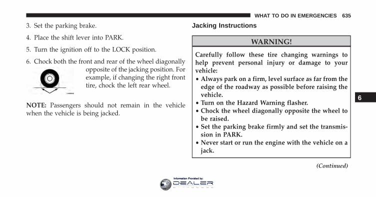
3. Set the parking brake.
4. Place the shift lever into PARK.
5. Turn the ignition off to the LOCK position.
6. Chock both the front and rear of the wheel diagonallyopposite of the jacking position. Forexample, if changing the right fronttire, chock the left rear wheel.
NOTE: Passengers should not remain in the vehiclewhen the vehicle is being jacked.
Jacking Instructions
WARNING!
Carefully follow these tire changing warnings tohelp prevent personal injury or damage to yourvehicle:• Always park on a firm, level surface as far from the
edge of the roadway as possible before raising thevehicle.
• Turn on the Hazard Warning flasher.• Chock the wheel diagonally opposite the wheel to
be raised.• Set the parking brake firmly and set the transmis-
sion in PARK.• Never start or run the engine with the vehicle on a
jack.
(Continued)
6
WHAT TO DO IN EMERGENCIES 635
Information Provided by:
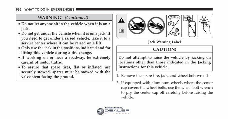
WARNING! (Continued)• Do not let anyone sit in the vehicle when it is on a
jack.• Do not get under the vehicle when it is on a jack. If
you need to get under a raised vehicle, take it to aservice center where it can be raised on a lift.
• Only use the jack in the positions indicated and forlifting this vehicle during a tire change.
• If working on or near a roadway, be extremelycareful of motor traffic.
• To assure that spare tires, flat or inflated, aresecurely stowed, spares must be stowed with thevalve stem facing the ground.
CAUTION!
Do not attempt to raise the vehicle by jacking onlocations other than those indicated in the JackingInstructions for this vehicle.
1. Remove the spare tire, jack, and wheel bolt wrench.
2. If equipped with aluminum wheels where the centercap covers the wheel bolts, use the wheel bolt wrenchto pry the center cap off carefully before raising thevehicle.
Jack Warning Label
636 WHAT TO DO IN EMERGENCIES
Information Provided by:
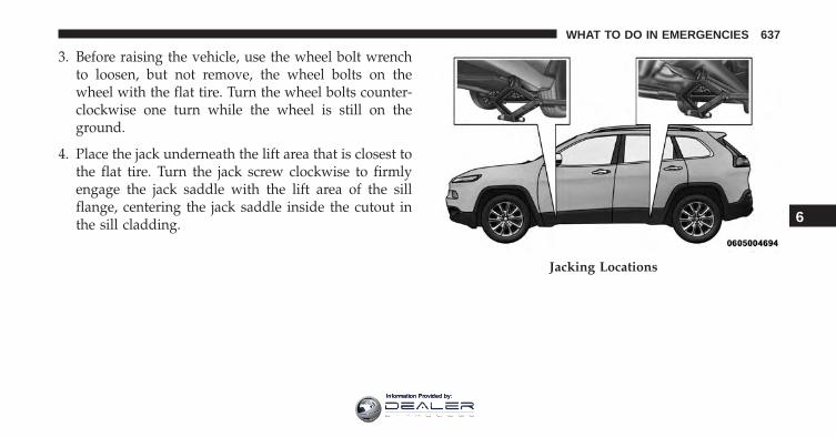
3. Before raising the vehicle, use the wheel bolt wrenchto loosen, but not remove, the wheel bolts on thewheel with the flat tire. Turn the wheel bolts counter-clockwise one turn while the wheel is still on theground.
4. Place the jack underneath the lift area that is closest tothe flat tire. Turn the jack screw clockwise to firmlyengage the jack saddle with the lift area of the sillflange, centering the jack saddle inside the cutout inthe sill cladding.
Jacking Locations
6
WHAT TO DO IN EMERGENCIES 637
Information Provided by:
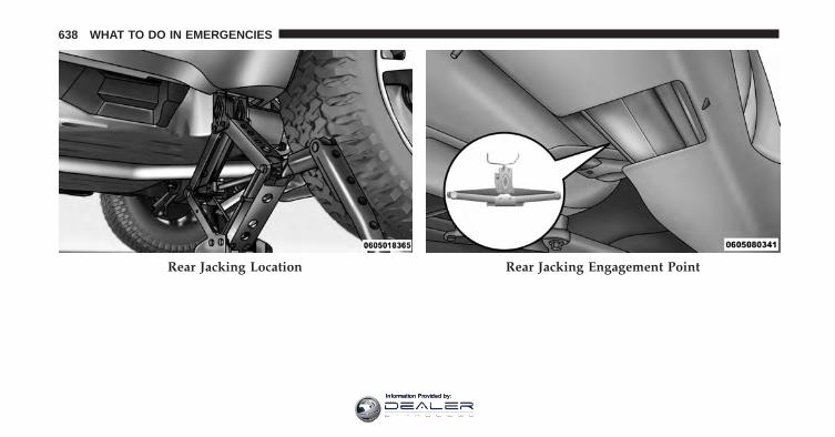
Rear Jacking Location Rear Jacking Engagement Point
638 WHAT TO DO IN EMERGENCIES
Information Provided by:
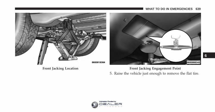
5. Raise the vehicle just enough to remove the flat tire.Front Jacking Location Front Jacking Engagement Point
6
WHAT TO DO IN EMERGENCIES 639
Information Provided by:
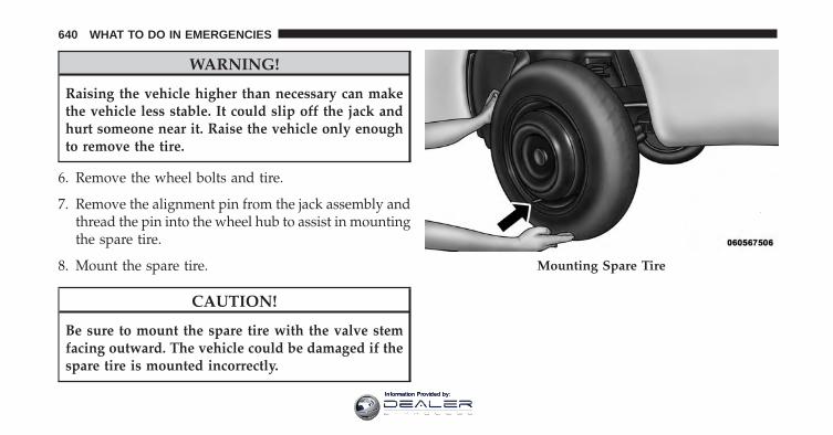
WARNING!
Raising the vehicle higher than necessary can makethe vehicle less stable. It could slip off the jack andhurt someone near it. Raise the vehicle only enoughto remove the tire.
6. Remove the wheel bolts and tire.
7. Remove the alignment pin from the jack assembly andthread the pin into the wheel hub to assist in mountingthe spare tire.
8. Mount the spare tire.
CAUTION!
Be sure to mount the spare tire with the valve stemfacing outward. The vehicle could be damaged if thespare tire is mounted incorrectly.
Mounting Spare Tire
640 WHAT TO DO IN EMERGENCIES
Information Provided by:
NOTE:
• For vehicles so equipped, do not attempt to install acenter cap or wheel cover on the compact spare.
• Refer to “Compact Spare Tire” and to “Limited-UseSpare” under “Tires—General Information” in“Starting and Operating” for additional warnings,cautions, and information about the spare tire, itsuse, and operation.
9. Install the wheel bolts with the threaded end of thewheel bolt toward the wheel. Lightly tighten thewheel bolts.
WARNING!
To avoid the risk of forcing the vehicle off the jack,do not fully tighten the wheel bolts until the vehiclehas been lowered. Failure to follow this warning mayresult in serious injury.
10. Lower the vehicle to the ground by turning the jackhandle counterclockwise.
11. Finish tightening the wheel bolts. Push down on thewrench while at the end of the handle for increasedleverage. Tighten the wheel bolts in a star patternuntil each wheel bolt has been tightened twice. Referto “Torque Specifications” in this section for theproper lug bolt torque. If in doubt about the correcttightness, have them checked with a torque wrenchby your authorized dealer or at a service station. 6
WHAT TO DO IN EMERGENCIES 641
Information Provided by:
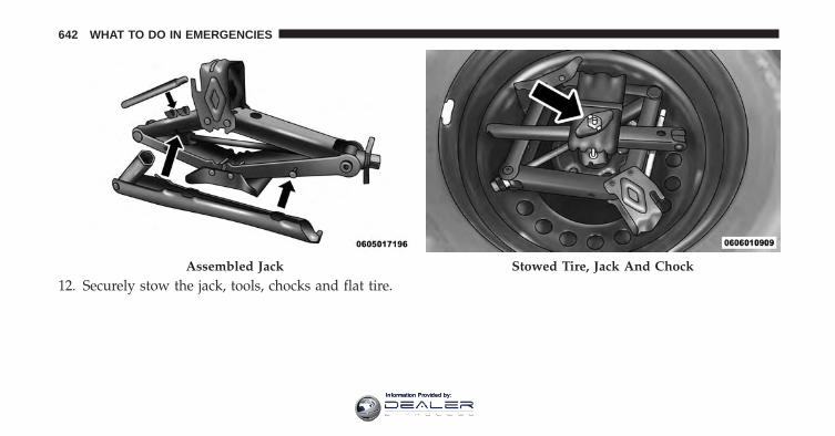
12. Securely stow the jack, tools, chocks and flat tire.Assembled Jack Stowed Tire, Jack And Chock
642 WHAT TO DO IN EMERGENCIES
Information Provided by:
WARNING!
A loose tire or jack thrown forward in a collision orhard stop could endanger the occupants of the ve-hicle. Always stow the jack parts and the spare tire inthe places provided. Have the deflated (flat) tirerepaired or replaced immediately.
Road Tire Installation
1. Mount the road tire on the axle.
2. Install the remaining wheel bolts with the threadedend of the wheel bolt toward the wheel. Lightlytighten the wheel bolts.
WARNING!
To avoid the risk of forcing the vehicle off the jack,do not tighten the lug nuts fully until the vehicle hasbeen lowered. Failure to follow this warning mayresult in serious injury.
3. Lower the vehicle to the ground by turning the jackhandle counterclockwise.
4. Finish tightening the wheel bolts. Push down on thewrench while at the end of the handle for increasedleverage. Tighten the wheel bolts in a star pattern untileach wheel bolt has been tightened twice. Refer to“Torque Specifications” in this section for the properlug bolt torque. If in doubt about the correct tightness,have them checked with a torque wrench by yourauthorized dealer or service station.
6
WHAT TO DO IN EMERGENCIES 643
Information Provided by:
5. Lower the jack until it is free. Remove the wheelchocks. Reassemble the lug wrench to the jack assem-bly and stow it in the spare tire area. Secure theassembly using the means provided. Release the park-ing brake before driving the vehicle.
6. After 25 miles (40 km) check the wheel bolt torquewith a torque wrench to ensure that all wheel bolts areproperly seated against the wheel.
JUMP-STARTING PROCEDURES
If your vehicle has a discharged battery it can be jump-started using a set of jumper cables and a battery inanother vehicle or by using a portable battery boosterpack. Jump-starting can be dangerous if done improperlyso please follow the procedures in this section carefully.
NOTE: When using a portable battery booster packfollow the manufacturer’s operating instructions andprecautions.
CAUTION!
Do not use a portable battery booster pack or anyother booster source with a system voltage greaterthan 12 Volts or damage to the battery, starter motor,alternator or electrical system may occur.
WARNING!
Do not attempt jump-starting if the battery is frozen.It could rupture or explode and cause personal injury.
644 WHAT TO DO IN EMERGENCIES
Information Provided by:
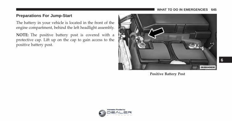
Preparations For Jump-Start
The battery in your vehicle is located in the front of theengine compartment, behind the left headlight assembly.
NOTE: The positive battery post is covered with aprotective cap. Lift up on the cap to gain access to thepositive battery post.
Positive Battery Post
6
WHAT TO DO IN EMERGENCIES 645
Information Provided by:
WARNING!
• Take care to avoid the radiator cooling fan when-ever the hood is raised. It can start anytime theignition switch is ON. You can be injured bymoving fan blades.
• Remove any metal jewelry such as rings, watchbands and bracelets that could make an inadvertentelectrical contact. You could be seriously injured.
• Batteries contain sulfuric acid that can burn yourskin or eyes and generate hydrogen gas which isflammable and explosive. Keep open flames orsparks away from the battery.
1. Set the parking brake, shift the automatic transmissioninto PARK and turn the ignition to LOCK.
2. Turn off the heater, radio, and all unnecessary electri-cal accessories.
3. If using another vehicle to jump-start the battery, parkthe vehicle within the jumper cables reach, set theparking brake and make sure the ignition is OFF.
WARNING!
Do not allow vehicles to touch each other as thiscould establish a ground connection and personalinjury could result.
Jump Starting Procedure
WARNING!
Failure to follow this jump-starting procedure couldresult in personal injury or property damage due tobattery explosion.
646 WHAT TO DO IN EMERGENCIES
Information Provided by:
CAUTION!
Failure to follow these procedures could result indamage to the charging system of the booster vehicleor the discharged vehicle.
Connecting The Jumper Cables
1. Connect the positive (+) end of the jumper cable to thepositive (+) post of the discharged vehicle.
2. Connect the opposite end of the positive (+) jumpercable to the positive (+) post of the booster battery.
3. Connect the negative (-) end of the jumper cable to thenegative (-) post of the booster battery.
4. Connect the opposite end of the negative (-) jumpercable to a good engine ground (exposed metal part ofthe discharged vehicle’s engine) away from the batteryand the fuel injection system.
WARNING!
Do not connect the jumper cable to the negative (-)post of the discharged battery. The resulting electri-cal spark could cause the battery to explode andcould result in serious injury. Only use the specificground point, do not use any other exposed metalparts.
5. Start the engine in the vehicle that has the boosterbattery, let the engine idle a few minutes, and thenstart the engine in the vehicle with the dischargedbattery.
6
WHAT TO DO IN EMERGENCIES 647
Information Provided by:
6. Once the engine is started, remove the jumper cablesin the reverse sequence:
Disconnecting The Jumper Cables
1. Disconnect the negative (-) end of the jumper cablefrom the engine ground of the vehicle with the dis-charged battery.
2. Disconnect the opposite end of the negative (-) jumpercable from the negative (-) post of the booster battery.
3. Disconnect the positive (+) end of the jumper cablefrom the positive (+) post of the booster battery.
4. Disconnect the opposite end of the positive (+) jumpercable from the positive (+) post of the vehicle with thedischarged battery.
If frequent jump starting is required to start your vehicleyou should have the battery and charging system in-spected at your authorized dealer.
CAUTION!
Accessories plugged into the vehicle power outletsdraw power from the vehicle’s battery, even when notin use (i.e., cellular devices, etc.). Eventually, ifplugged in long enough without engine operation,the vehicle’s battery will discharge sufficiently todegrade battery life and/or prevent the engine fromstarting.
FREEING A STUCK VEHICLE
If your vehicle becomes stuck in mud, sand or snow, itcan often be moved using a rocking motion. Turn thesteering wheel right and left to clear the area around thefront wheels. Press and hold the lock button on the shiftlever. Then shift back and forth between DRIVE andREVERSE, while gently pressing the accelerator.
648 WHAT TO DO IN EMERGENCIES
Information Provided by:
NOTE: Shifts between DRIVE and REVERSE can only beachieved at wheel speeds of 5 mph (8 km/h) or less.Whenever the transmission remains in NEUTRAL formore than two seconds, you must push the brake pedalto engage DRIVE or REVERSE.
Use the least amount of accelerator pedal pressure thatwill maintain the rocking motion without spinning thewheels or racing the engine.
CAUTION!
• Racing the engine or spinning the wheels may leadto transmission overheating and failure. Allow theengine to idle with the transmission in NEUTRALfor at least one minute after every five rocking-motion cycles. This will minimize overheating andreduce the risk of transmission failure during pro-longed efforts to free a stuck vehicle.
(Continued)
CAUTION! (Continued)• When “rocking” a stuck vehicle by shifting be-
tween DRIVE and REVERSE, do not spin thewheels faster than 15 mph (24 km/h), or drivetraindamage may result.
• Revving the engine or spinning the wheels too fastmay lead to transmission overheating and failure.It can also damage the tires. Do not spin the wheelsabove 30 mph (48 km/h) while in gear (no trans-mission shifting occurring).
NOTE: Push the “ESC Off” switch (if necessary), to placethe Electronic Stability Control (ESC) system in “PartialOff” mode, before rocking the vehicle. Refer to “Elec-tronic Brake Control” in “Starting And Operating” forfurther information. Once the vehicle has been freed,push the �ESC Off� switch again to restore “ESC On”mode.
6
WHAT TO DO IN EMERGENCIES 649
Information Provided by:
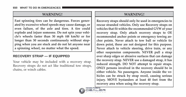
WARNING!
Fast spinning tires can be dangerous. Forces gener-ated by excessive wheel speeds may cause damage, oreven failure, of the axle and tires. A tire couldexplode and injure someone. Do not spin your vehi-cle’s wheels faster than 30 mph (48 km/h) or forlonger than 30 seconds continuously without stop-ping when you are stuck and do not let anyone neara spinning wheel, no matter what the speed.
RECOVERY STRAP — IF EQUIPPED
Your vehicle may be included with a recovery strap.Recovery straps do not act like traditional tow straps,chains, or winch cables.
WARNING!
Recovery straps should only be used in emergencies torescue stranded vehicles. Only use Recovery straps onvehicles that fit within the recommended GVW of yourrecovery strap. Only attach recovery straps to OErecommended anchor points or emergency towing an-chor points. Never attach to tow ball or vehicle tiedown point, these are not designed for this purpose.Never attach to vehicle steering, drive train, or anyother suspension components. NEVER pull a strapover sharp edges or abrasive surfaces that can damagethe recovery strap. NEVER use a damaged strap, it hasreduced strength. DO NOT attempt to repair straps.ONLY persons involved in the recovery should be ineither vehicle. No passengers. Anyone inside the ve-hicles can be struck by strap recoil, causing seriousinjury. MOVE bystanders at least 40 feet from therecovery area when using the recovery strap.
650 WHAT TO DO IN EMERGENCIES
Information Provided by:
Using Recovery Strap
1. Review all warnings and instructions first.
2. Position the recovery vehicle.
3. Connect the recovery strap.
4. Add a recovery damper or blanket.
5. Clear the danger zone.
6. Safely and slowly start pulling.
7. Disconnect the recovery strap after both vehicle aresecure and parked.
SHIFT LEVER OVERRIDE
If a malfunction occurs and the shift lever cannot bemoved out of the PARK position, you can use thefollowing procedure to temporarily move the shift lever:
1. Turn the engine OFF.
2. Apply the parking brake.
3. Using a screwdriver or similar tool, carefully separatethe shifter bezel and boot assembly from the centerconsole.
4. Press and maintain firm pressure on the brake pedal.
5. Insert a small screwdriver or similar tool down intothe shift lever override access hole (at the right frontcorner of the shift lever assembly), and push and holdthe override release lever down.
6. Move the shift lever to the NEUTRAL position.
7. The vehicle may then be started in NEUTRAL.
8. Reinstall the shift lever boot.
6
WHAT TO DO IN EMERGENCIES 651
Information Provided by:
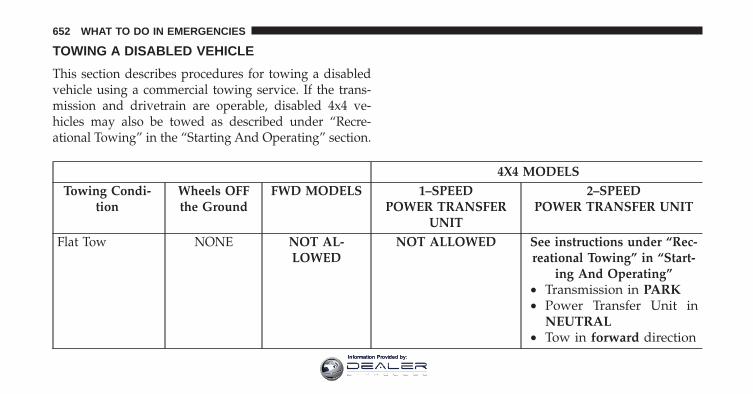
TOWING A DISABLED VEHICLE
This section describes procedures for towing a disabledvehicle using a commercial towing service. If the trans-mission and drivetrain are operable, disabled 4x4 ve-hicles may also be towed as described under “Recre-ational Towing” in the “Starting And Operating” section.
4X4 MODELSTowing Condi-
tionWheels OFFthe Ground
FWD MODELS 1–SPEEDPOWER TRANSFER
UNIT
2–SPEEDPOWER TRANSFER UNIT
Flat Tow NONE NOT AL-LOWED
NOT ALLOWED See instructions under “Rec-reational Towing” in “Start-
ing And Operating”• Transmission in PARK• Power Transfer Unit in
NEUTRAL• Tow in forward direction
652 WHAT TO DO IN EMERGENCIES
Information Provided by:
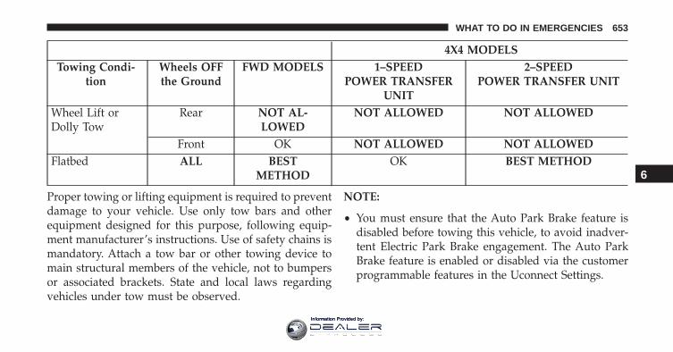
4X4 MODELSTowing Condi-
tionWheels OFFthe Ground
FWD MODELS 1–SPEEDPOWER TRANSFER
UNIT
2–SPEEDPOWER TRANSFER UNIT
Wheel Lift orDolly Tow
Rear NOT AL-LOWED
NOT ALLOWED NOT ALLOWED
Front OK NOT ALLOWED NOT ALLOWEDFlatbed ALL BEST
METHODOK BEST METHOD
Proper towing or lifting equipment is required to preventdamage to your vehicle. Use only tow bars and otherequipment designed for this purpose, following equip-ment manufacturer’s instructions. Use of safety chains ismandatory. Attach a tow bar or other towing device tomain structural members of the vehicle, not to bumpersor associated brackets. State and local laws regardingvehicles under tow must be observed.
NOTE:
• You must ensure that the Auto Park Brake feature isdisabled before towing this vehicle, to avoid inadver-tent Electric Park Brake engagement. The Auto ParkBrake feature is enabled or disabled via the customerprogrammable features in the Uconnect Settings.
6
WHAT TO DO IN EMERGENCIES 653
Information Provided by:
• Vehicles with a discharged battery or total electricalfailure when the electric parking brake (EPB) is engaged,will need a wheel dolly or jack to raise the rear wheelsoff the ground when moving the vehicle onto a flatbed.
If you must use the accessories (wipers, defrosters, etc.)while being towed, the ignition must be in the ON/RUNposition, not the ACC position. Note that the Safeholdfeature will engage the Electric Park Brake whenever thedriver’s door is opened (if the ignition is ON, transmis-sion is not in PARK, and brake pedal is released). If youare towing this vehicle with the ignition in the ON/RUNposition, you must manually disable the Electric ParkBrake each time the driver’s door is opened, by pressingthe brake pedal and then pushing the EPB switch down.
If the key fob is unavailable, or the vehicle’s battery isdischarged, refer to “Shift Lever Override” in this sectionfor instructions on shifting the transmission out of PARKso that the vehicle can be moved.
CAUTION!
• Do not use sling type equipment when towing.Vehicle damage may occur.
• When securing the vehicle to a flat bed truck, donot attach to front or rear suspension components.Damage to your vehicle may result from impropertowing.
• Ensure that the Electric Park Brake is released, andremains released, while being towed.
Front-Wheel Drive (FWD) Models
The manufacturer recommends towing your vehicle withall four wheels OFF the ground using a flatbed.
If flatbed equipment is not available, this vehicle musttowed with the front wheels OFF the ground (using atowing dolly, or wheel lift equipment with the frontwheels raised).
654 WHAT TO DO IN EMERGENCIES
Information Provided by:
Ensure that the Electric Park Brake is released, andremains released, while being towed.
CAUTION!
Towing this vehicle in violation of the above require-ments can cause severe transmission damage. Dam-age from improper towing is not covered under theNew Vehicle Limited Warranty.
4x4 Models With 1–Speed Power Transfer Unit
The manufacturer requires towing with all four wheelsOFF the ground.
Acceptable methods are to tow the vehicle on a flatbed,or with one end of vehicle raised and the opposite end ona towing dolly.
CAUTION!
• DO NOT tow this vehicle with ANY of its wheelson the ground. Damage to the drivetrain will result.
• Front or rear wheel lifts must not be used. Internaldamage to the transmission or power transfer unitwill occur if a front or rear wheel lift is used whentowing.
• Towing this vehicle in violation of the above re-quirements can cause severe transmission and/orpower transfer unit damage. Damage from im-proper towing is not covered under the New Ve-hicle Limited Warranty.
6
WHAT TO DO IN EMERGENCIES 655
Information Provided by:
4x4 Models With 2–Speed Power Transfer Unit
The manufacturer recommends towing with all fourwheels OFF the ground.
Acceptable methods are to tow the vehicle on a flatbed orwith one end of the vehicle raised and the opposite endon a towing dolly.
If flatbed equipment is not available and the PowerTransfer Unit is operable, vehicles with a 2–speed PowerTransfer Unit may be towed (in the forward direction,with ALL wheels on the ground), under the followingconditions:
• The Power Transfer Unit must be in NEUTRAL (N).
• The transmission must be in PARK.
• Ensure that the Electric Park Brake is released, andremains released, while being towed.
Refer to “Recreational Towing” in “Starting and Operat-ing” for detailed instructions.
CAUTION!
• Front or rear wheel lifts must not be used. Internaldamage to the transmission or power transfer unitwill occur if a front or rear wheel lift is used whentowing.
• Towing this vehicle in violation of the above re-quirements can cause severe transmission and/orpower transfer unit damage. Damage from im-proper towing is not covered under the New Ve-hicle Limited Warranty.
656 WHAT TO DO IN EMERGENCIES
Information Provided by:
MAINTAINING YOUR VEHICLE
CONTENTS� ENGINE COMPARTMENT — 2.4L . . . . . . . . . .659
� ENGINE COMPARTMENT — 3.2L . . . . . . . . . .660
� ONBOARD DIAGNOSTIC SYSTEM — OBD II . .661
▫ Loose Fuel Filler Cap Message . . . . . . . . . . . .661
� EMISSIONS INSPECTION AND MAINTENANCEPROGRAMS . . . . . . . . . . . . . . . . . . . . . . . . . .662
� REPLACEMENT PARTS . . . . . . . . . . . . . . . . . .663
� DEALER SERVICE . . . . . . . . . . . . . . . . . . . . . .664
� MAINTENANCE PROCEDURES . . . . . . . . . . .664
▫ Engine Oil . . . . . . . . . . . . . . . . . . . . . . . . . .665
▫ Engine Oil Filter . . . . . . . . . . . . . . . . . . . . . .668
▫ Engine Air Cleaner Filter . . . . . . . . . . . . . . . .669
▫ Accessory Drive Belt Inspection . . . . . . . . . . .672
▫ Maintenance-Free Battery . . . . . . . . . . . . . . .674
▫ Air Conditioner Maintenance . . . . . . . . . . . . .675
▫ Body Lubrication . . . . . . . . . . . . . . . . . . . . .679
▫ Windshield Wiper Blades . . . . . . . . . . . . . . .680
▫ Adding Washer Fluid . . . . . . . . . . . . . . . . . .687
▫ Exhaust System . . . . . . . . . . . . . . . . . . . . . .688
▫ Cooling System . . . . . . . . . . . . . . . . . . . . . .690
7
Information Provided by:
▫ Brake System . . . . . . . . . . . . . . . . . . . . . . . .696
▫ Automatic Transmission . . . . . . . . . . . . . . . .698
▫ Appearance Care And Protection FromCorrosion . . . . . . . . . . . . . . . . . . . . . . . . . . .700
� FUSES . . . . . . . . . . . . . . . . . . . . . . . . . . . . . .706
▫ Power Distribution Center . . . . . . . . . . . . . . .707
▫ Interior Fuses . . . . . . . . . . . . . . . . . . . . . . . .716
� VEHICLE STORAGE . . . . . . . . . . . . . . . . . . . .718
� REPLACEMENT BULBS . . . . . . . . . . . . . . . . .718
� BULB REPLACEMENT . . . . . . . . . . . . . . . . . .720
▫ Low Beam And High Beam Headlamps . . . . .720
▫ Front Turn Signals And Front Side MarkerLamps . . . . . . . . . . . . . . . . . . . . . . . . . . . . .721
▫ Front Fog Lamp . . . . . . . . . . . . . . . . . . . . . .722
▫ Front Fog Lamp (Trailhawk) . . . . . . . . . . . . .722
▫ Bodyside Mounted Back-up Lamp . . . . . . . . .723
▫ Liftgate Mounted Back-up Lamp . . . . . . . . . .723
▫ License Plate Lamp . . . . . . . . . . . . . . . . . . . .724
� FLUID CAPACITIES . . . . . . . . . . . . . . . . . . . .725
� FLUIDS, LUBRICANTS, AND GENUINEPARTS . . . . . . . . . . . . . . . . . . . . . . . . . . . . . .726
▫ Engine . . . . . . . . . . . . . . . . . . . . . . . . . . . . .726
▫ Chassis . . . . . . . . . . . . . . . . . . . . . . . . . . . .728
658 MAINTAINING YOUR VEHICLE
Information Provided by:
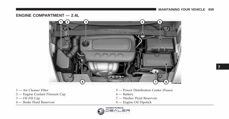
ENGINE COMPARTMENT — 2.4L
1 — Air Cleaner Filter 5 — Power Distribution Center (Fuses)2 — Engine Coolant Pressure Cap 6 — Battery3 — Oil Fill Cap 7 — Washer Fluid Reservoir4 — Brake Fluid Reservoir 8 — Engine Oil Dipstick
7
MAINTAINING YOUR VEHICLE 659
Information Provided by:
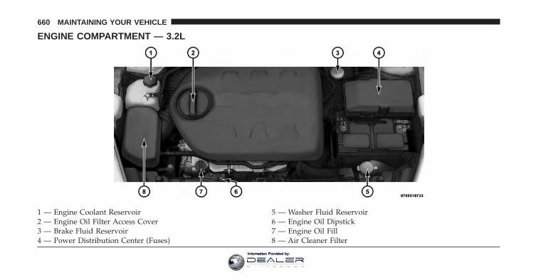
ENGINE COMPARTMENT — 3.2L
1 — Engine Coolant Reservoir 5 — Washer Fluid Reservoir2 — Engine Oil Filter Access Cover 6 — Engine Oil Dipstick3 — Brake Fluid Reservoir 7 — Engine Oil Fill4 — Power Distribution Center (Fuses) 8 — Air Cleaner Filter
660 MAINTAINING YOUR VEHICLE
Information Provided by:
ONBOARD DIAGNOSTIC SYSTEM — OBD II
Your vehicle is equipped with a sophisticated OnboardDiagnostic system called OBD II. This system monitorsthe performance of the emissions, engine, and automatictransmission control systems. When these systems areoperating properly, your vehicle will provide excellentperformance and fuel economy, as well as engine emis-sions well within current government regulations.
If any of these systems require service, the OBD II systemwill turn on the Malfunction Indicator Light (MIL). It willalso store diagnostic codes and other information toassist your service technician in making repairs. Al-though your vehicle will usually be drivable and notneed towing, see your authorized dealer for service assoon as possible.
CAUTION!
• Prolonged driving with the MIL on could causefurther damage to the emission control system. Itcould also affect fuel economy and driveability.The vehicle must be serviced before any emissionstests can be performed.
• If the MIL is flashing while the engine is running,severe catalytic converter damage and power losswill soon occur. Immediate service is required.
Loose Fuel Filler Cap Message
If the vehicle diagnostic system determines that the fuelfiller cap is loose, improperly installed, or damaged, a“CHECK GASCAP” message will be displayed in theElectronic Vehicle Information Center (EVIC) or DriverInformation Display (DID). Refer to “Electronic VehicleInformation (EVIC) or �Driver Information Display(DID)” in “Understanding Your Instrument Panel” for
7
MAINTAINING YOUR VEHICLE 661
Information Provided by:
further information. Tighten the fuel filler cap until a“clicking” sound is heard. This is an indication that thefuel filler cap is properly tightened. Refer to “OnboardDiagnostic System” in “Maintaining Your Vehicle” forfurther information.
EMISSIONS INSPECTION AND MAINTENANCEPROGRAMS
In some localities, it may be a legal requirement to passan inspection of your vehicle’s emissions control system.Failure to pass could prevent vehicle registration.
For states that require an Inspection and Mainte-nance (I/M), this check verifies the “MalfunctionIndicator Light (MIL)” is functioning and is not
on when the engine is running, and that the OBD IIsystem is ready for testing.
Normally, the OBD II system will be ready. The OBD IIsystem may not be ready if your vehicle was recently
serviced, recently had a dead battery or a battery replace-ment. If the OBD II system should be determined notready for the I/M test, your vehicle may fail the test.
Your vehicle has a simple ignition actuated test, whichyou can use prior to going to the test station. To check ifyour vehicle’s OBD II system is ready, you must do thefollowing:
1. Cycle the ignition switch to the ON position, but donot crank or start the engine.
NOTE: If you crank or start the engine, you will have tostart this test over.
2. As soon as you cycle the ignition switch to the ONposition, you will see the Malfunction Indicator Light(MIL) symbol come on as part of a normal bulb check.
662 MAINTAINING YOUR VEHICLE
Information Provided by:
3. Approximately 15 seconds later, one of two things willhappen:
• The MIL will flash for about 10 seconds and thenreturn to being fully illuminated until you turn OFFthe ignition or start the engine. This means that yourvehicle’s OBD II system is not ready and you shouldnot proceed to the I/M station.
• The MIL will not flash at all and will remain fullyilluminated until you place the ignition in the offposition or start the engine. This means that yourvehicle’s OBD II system is ready and you can proceedto the I/M station.
If your OBD II system is not ready, you should see yourauthorized dealer or repair facility. If your vehicle wasrecently serviced or had a battery failure or replacement,you may need to do nothing more than drive yourvehicle as you normally would in order for your OBD II
system to update. A recheck with the above test routinemay then indicate that the system is now ready.
Regardless of whether your vehicle’s OBD II system isready or not, if the MIL is illuminated during normalvehicle operation you should have your vehicle servicedbefore going to the I/M station. The I/M station can failyour vehicle because the MIL is on with the enginerunning.
REPLACEMENT PARTS
Use of genuine MOPAR parts for normal/scheduledmaintenance and repairs is highly recommended to en-sure the designed performance. Damage or failurescaused by the use of non-MOPAR parts for maintenanceand repairs will not be covered by the New VehicleLimited Warranty.
7
MAINTAINING YOUR VEHICLE 663
Information Provided by:
DEALER SERVICE
Your authorized dealer has the qualified service person-nel, special tools, and equipment to perform all serviceoperations in an expert manner. Service Manuals areavailable which include detailed service information foryour vehicle. Refer to these Service Manuals beforeattempting any procedure yourself.
NOTE: Intentional tampering with emissions controlsystems may void your warranty and could result in civilpenalties being assessed against you.
WARNING!
You can be badly injured working on or around amotor vehicle. Only do service work for which youhave the knowledge and the proper equipment. If youhave any doubt about your ability to perform a servicejob, take your vehicle to a competent mechanic.
MAINTENANCE PROCEDURES
The pages that follow contain the required maintenanceservices determined by the engineers who designed yourvehicle.
Besides those maintenance items specified in the fixed“Maintenance Schedule”, there are other componentswhich may require servicing or replacement in the future.
CAUTION!
• Failure to properly maintain your vehicle or per-form repairs and service when necessary couldresult in more costly repairs, damage to othercomponents or negatively impact vehicle perfor-mance. Immediately have potential malfunctionsexamined by an authorized dealer or qualifiedrepair center.
(Continued)
664 MAINTAINING YOUR VEHICLE
Information Provided by:
CAUTION! (Continued)• Your vehicle has been built with improved fluids
that protect the performance and durability of yourvehicle and also allow extended maintenance inter-vals. Do not use chemical flushes in these compo-nents as the chemicals can damage your engine,transmission or air conditioning. Such damage isnot covered by the New Vehicle Limited Warranty.If a flush is needed because of component malfunc-tion, use only the specified fluid for the flushingprocedure.
Engine Oil
Checking Oil Level
To assure proper engine lubrication, the engine oil mustbe maintained at the correct level. Check the oil level at
regular intervals, such as every month. The best time tocheck the engine oil level is about five minutes after afully warmed up engine is shut off.
Checking the oil while the vehicle is on level ground willimprove the accuracy of the oil level readings.
There are three possible dipstick types,
• Crosshatched zone.
• Crosshatched zone marked SAFE.
• Crosshatched zone marked with MIN at the low end ofthe range and MAX at the high end of the range.
NOTE: Always maintain the oil level within the cross-hatch markings on the dipstick.
Adding 1 quart (1.0 liters) of oil when the reading is at thelow end of the dipstick range will raise the oil level to thehigh end of the range marking.
7
MAINTAINING YOUR VEHICLE 665
Information Provided by:
CAUTION!
Overfilling or underfilling the crankcase will causeaeration or loss of oil pressure. This could damageyour engine.
Change Engine Oil
The oil change indicator system will remind you that it istime to take your vehicle in for scheduled maintenance.Refer to the “Maintenance Schedule” for further informa-tion.
NOTE: Under no circumstances should oil change inter-vals exceed 10,000 miles (16,000 km), twelve months or350 hours of engine run time, whichever comes first. The350 hours of engine run or idle time is generally only aconcern for fleet customers.
Engine Oil Selection
For best performance and maximum protection under alltypes of operating conditions, the manufacturer onlyrecommends engine oils that are API Certified and meetthe requirements of FCA US Material Standard MS-6395.
American Petroleum Institute (API) Engine OilIdentification Symbol
This symbol means that the oil hasbeen certified by the AmericanPetroleum Institute (API). Themanufacturer only recommendsAPI Certified engine oils.
This symbol certifies 0W-20, 5W-20, 0W-30, 5W-30 and 10W-30 en-gine oils.
666 MAINTAINING YOUR VEHICLE
Information Provided by:
CAUTION!
Do not use chemical flushes in your engine oil as thechemicals can damage your engine. Such damage isnot covered by the New Vehicle Limited Warranty.
Engine Oil Viscosity (SAE Grade) — 2.0L, 2.4LEngine
MOPAR SAE 0W-20 engine oil approved to FCA USMaterial Standard MS-6395 such as Pennzoil, Shell Helixor equivalent is recommended for all operating tempera-tures. This engine oil improves low temperature startingand vehicle fuel economy.
The engine oil filler cap also shows the recommendedengine oil viscosity for your engine. For information onengine oil filler cap location, refer to “Engine Compart-ment” in this section.
Lubricants which do not have both the engine oil certi-fication mark and the correct SAE viscosity grade num-ber should not be used.
Engine Oil Viscosity (SAE Grade) — 3.2L Engine
MOPAR SAE 5W-20 engine oil or equivalent Pennzoil orShell Helix is recommended for all operating tempera-tures. This engine oil improves low temperature startingand vehicle fuel economy. The engine oil filler cap alsoshows the recommended engine oil viscosity for yourengine. For information on engine oil filler cap location,refer to “Engine Compartment” in “Maintaining YourVehicle” for further information.
Lubricants which do not have both the engine oil certi-fication mark and the correct SAE viscosity grade num-ber should not be used.
7
MAINTAINING YOUR VEHICLE 667
Information Provided by:
Synthetic Engine Oils
You may use synthetic engine oils provided the recom-mended oil quality requirements are met, and the recom-mended maintenance intervals for oil and filter changesare followed.
Synthetic engine oils which do not have both the engineoil certification mark and the correct SAE viscosity gradenumber should not be used.
Materials Added To Engine Oil
The manufacturer strongly recommends against the addi-tion of any additives (other than leak detection dyes) to theengine oil. Engine oil is an engineered product and itsperformance may be impaired by supplemental additives.
Disposing Of Used Engine Oil And Oil Filters
Care should be taken in disposing of used engine oil andoil filters from your vehicle. Used oil and oil filters,indiscriminately discarded, can present a problem to the
environment. Contact your authorized dealer, servicestation or governmental agency for advice on how andwhere used oil and oil filters can be safely discarded inyour area.
Engine Oil Filter
The engine oil filter should be replaced with a new filterat every engine oil change.
Engine Oil Filter Selection
This manufacturer’s engines have a full-flow type dispos-able oil filter. Use a filter of this type for replacement. Thequality of replacement filters varies considerably. Onlyhigh quality filters should be used to assure most efficientservice. MOPAR engine oil filters are high quality oilfilters and are recommended.
668 MAINTAINING YOUR VEHICLE
Information Provided by:
Engine Air Cleaner Filter
Refer to the “Maintenance Schedule” for the propermaintenance intervals.
NOTE: Be sure to follow the “Sever Duty Conditions”maintenance interval if applicable.
WARNING!
The air induction system (air cleaner, hoses, etc.) canprovide a measure of protection in the case of enginebackfire. Do not remove the air induction system (aircleaner, hoses, etc.) unless such removal is necessaryfor repair or maintenance. Make sure that no one isnear the engine compartment before starting thevehicle with the air induction system (air cleaner,hoses, etc.) removed. Failure to do so can result inserious personal injury.
Engine Air Cleaner Filter Selection
The quality of replacement engine air cleaner filtersvaries considerably. Only high quality filters should beused to assure most efficient service. MOPAR engine aircleaner filters are a high quality filter and are recom-mended.
Engine Air Cleaner Filter Inspection andReplacement
Inspect engine air cleaner filter for dirt and or debris, ifyou find evidence of either dirt or debris you shouldchange your air cleaner filter.
Engine Air Cleaner Filter Removal
1. Remove the screws from the air cleaner cover.
7
MAINTAINING YOUR VEHICLE 669
Information Provided by:
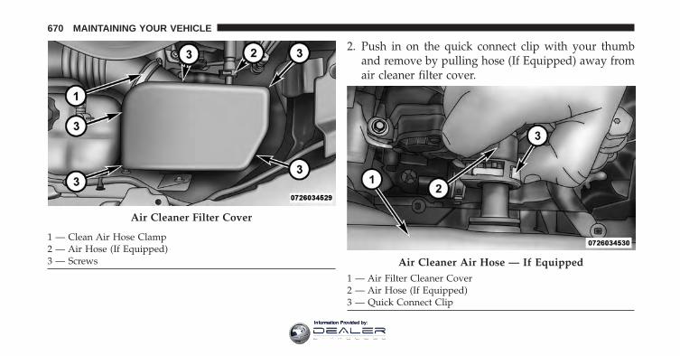
2. Push in on the quick connect clip with your thumband remove by pulling hose (If Equipped) away fromair cleaner filter cover.
Air Cleaner Filter Cover
1 — Clean Air Hose Clamp2 — Air Hose (If Equipped)3 — Screws Air Cleaner Air Hose — If Equipped
1 — Air Filter Cleaner Cover2 — Air Hose (If Equipped)3 — Quick Connect Clip
670 MAINTAINING YOUR VEHICLE
Information Provided by:
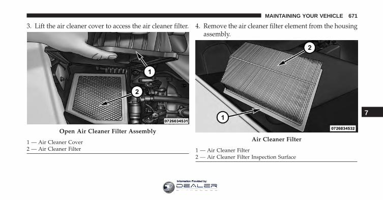
3. Lift the air cleaner cover to access the air cleaner filter. 4. Remove the air cleaner filter element from the housingassembly.
Open Air Cleaner Filter Assembly
1 — Air Cleaner Cover2 — Air Cleaner Filter
Air Cleaner Filter
1 — Air Cleaner Filter2 — Air Cleaner Filter Inspection Surface
7
MAINTAINING YOUR VEHICLE 671
Information Provided by:
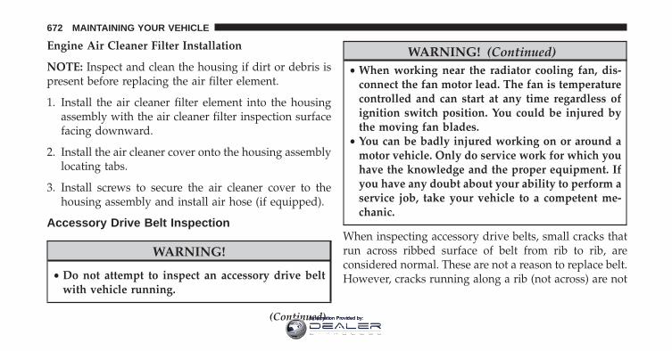
Engine Air Cleaner Filter Installation
NOTE: Inspect and clean the housing if dirt or debris ispresent before replacing the air filter element.
1. Install the air cleaner filter element into the housingassembly with the air cleaner filter inspection surfacefacing downward.
2. Install the air cleaner cover onto the housing assemblylocating tabs.
3. Install screws to secure the air cleaner cover to thehousing assembly and install air hose (if equipped).
Accessory Drive Belt Inspection
WARNING!
• Do not attempt to inspect an accessory drive beltwith vehicle running.
(Continued)
WARNING! (Continued)• When working near the radiator cooling fan, dis-
connect the fan motor lead. The fan is temperaturecontrolled and can start at any time regardless ofignition switch position. You could be injured bythe moving fan blades.
• You can be badly injured working on or around amotor vehicle. Only do service work for which youhave the knowledge and the proper equipment. Ifyou have any doubt about your ability to perform aservice job, take your vehicle to a competent me-chanic.
When inspecting accessory drive belts, small cracks thatrun across ribbed surface of belt from rib to rib, areconsidered normal. These are not a reason to replace belt.However, cracks running along a rib (not across) are not
672 MAINTAINING YOUR VEHICLE
Information Provided by:
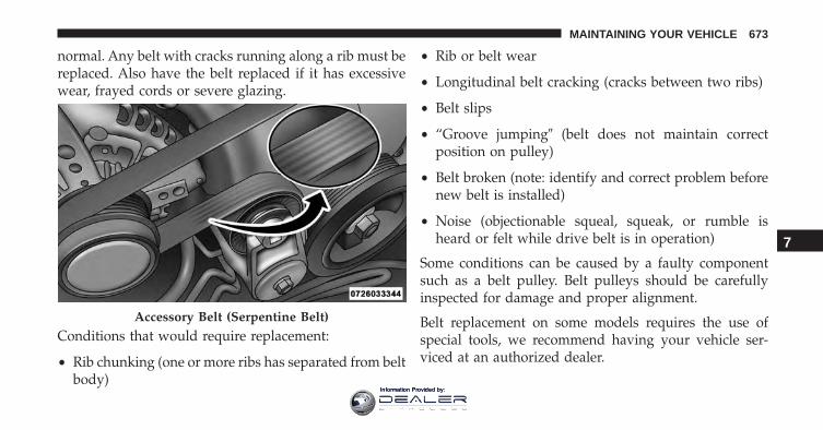
normal. Any belt with cracks running along a rib must bereplaced. Also have the belt replaced if it has excessivewear, frayed cords or severe glazing.
Conditions that would require replacement:
• Rib chunking (one or more ribs has separated from beltbody)
• Rib or belt wear
• Longitudinal belt cracking (cracks between two ribs)
• Belt slips
• “Groove jumping� (belt does not maintain correctposition on pulley)
• Belt broken (note: identify and correct problem beforenew belt is installed)
• Noise (objectionable squeal, squeak, or rumble isheard or felt while drive belt is in operation)
Some conditions can be caused by a faulty componentsuch as a belt pulley. Belt pulleys should be carefullyinspected for damage and proper alignment.
Belt replacement on some models requires the use ofspecial tools, we recommend having your vehicle ser-viced at an authorized dealer.
Accessory Belt (Serpentine Belt)
7
MAINTAINING YOUR VEHICLE 673
Information Provided by:
Maintenance-Free Battery
Your vehicle is equipped with a maintenance-free battery.You will never have to add water, nor is periodic main-tenance required.
WARNING!
• Battery fluid is a corrosive acid solution and canburn or even blind you. Do not allow battery fluidto contact your eyes, skin, or clothing. Do not leanover a battery when attaching clamps. If acidsplashes in eyes or on skin, flush the area imme-diately with large amounts of water. Refer to“Jump-Starting Procedures” in “What To Do InEmergencies” for further information.
• Battery gas is flammable and explosive. Keepflame or sparks away from the battery. Do not usea booster battery or any other booster source with
(Continued)
WARNING! (Continued)an output greater than 12 Volts. Do not allow cableclamps to touch each other.
• Battery posts, terminals, and related accessoriescontain lead and lead compounds. Wash handsafter handling.
CAUTION!
• It is essential when replacing the cables on thebattery that the positive cable is attached to thepositive post and the negative cable is attached tothe negative post. Battery posts are marked positive(+) and negative (-) and are identified on thebattery case. Cable clamps should be tight on theterminal posts and free of corrosion.
(Continued)
674 MAINTAINING YOUR VEHICLE
Information Provided by:
CAUTION! (Continued)• If a “fast charger” is used while the battery is in the
vehicle, disconnect both vehicle battery cables be-fore connecting the charger to the battery. Do notuse a “fast charger” to provide starting voltage.
Air Conditioner Maintenance
For best possible performance, your air conditioner shouldbe checked and serviced by an authorized dealer at thestart of each warm season. This service should includecleaning of the condenser fins and a performance test.Drive belt tension should also be checked at this time.
WARNING!
• Use only refrigerants and compressor lubricantsapproved by the manufacturer for your air condi-tioning system. Some unapproved refrigerants areflammable and can explode, injuring you. Otherunapproved refrigerants or lubricants can cause thesystem to fail, requiring costly repairs. Refer toWarranty Information Book, located on the DVD,for further warranty information.
• The air conditioning system contains refrigerantunder high pressure. To avoid risk of personalinjury or damage to the system, adding refrigerantor any repair requiring lines to be disconnectedshould be done by an experienced technician.
7
MAINTAINING YOUR VEHICLE 675
Information Provided by:
CAUTION!
Do not use chemical flushes in your air conditioningsystem as the chemicals can damage your air condi-tioning components. Such damage is not covered bythe New Vehicle Limited Warranty.
Refrigerant Recovery And Recycling R134a — IfEquipped
R-134a Air Conditioning Refrigerant is a hydrofluoro-carbon (HFC) that is endorsed by the EnvironmentalProtection Agency and is an ozone-saving product. How-ever, the manufacturer recommends that air conditioningservice be performed by authorized dealer or otherservice facilities using recovery and recycling equipment.
NOTE: Use only manufacturer approved A/C systemPAG compressor oil and refrigerants.
Refrigerant Recovery And Recycling HFO 1234yf— If Equipped
HFO 1234yf Air Conditioning Refrigerant is a hydro-fluoolefine HFO that is endorsed by the EnvironmentalProtection Agency and is an ozone-saving product with alow GWP (Global Warming Potential). However, themanufacturer recommends that air conditioning servicebe performed by authorized dealer or other servicefacilities using recovery and recycling equipment.
NOTE: Use only manufacturer approved A/C systemPAG compressor oil and refrigerants.
676 MAINTAINING YOUR VEHICLE
Information Provided by:
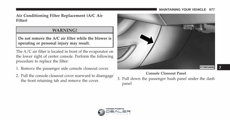
Air Conditioning Filter Replacement (A/C AirFilter)
WARNING!
Do not remove the A/C air filter while the blower isoperating or personal injury may result.
The A/C air filter is located in front of the evaporator onthe lower right of center console. Perform the followingprocedure to replace the filter:
1. Remove the passenger side console closeout cover.
2. Pull the console closeout cover rearward to disengagethe front retaining tab and remove the cover. 3. Pull down the passenger hush panel under the dash
panel
Console Closeout Panel
7
MAINTAINING YOUR VEHICLE 677
Information Provided by:
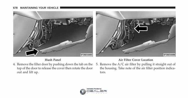
4. Remove the filter door by pushing down the tab on thetop of the door to release the cover then rotate the doorout and lift up.
5. Remove the A/C air filter by pulling it straight out ofthe housing. Take note of the air filter position indica-tors.
Hush Panel Air Filter Cover Location
678 MAINTAINING YOUR VEHICLE
Information Provided by:
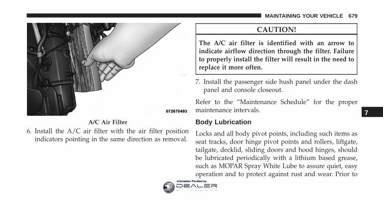
6. Install the A/C air filter with the air filter positionindicators pointing in the same direction as removal.
CAUTION!
The A/C air filter is identified with an arrow toindicate airflow direction through the filter. Failureto properly install the filter will result in the need toreplace it more often.
7. Install the passenger side hush panel under the dashpanel and console closeout.
Refer to the “Maintenance Schedule” for the propermaintenance intervals.
Body Lubrication
Locks and all body pivot points, including such items asseat tracks, door hinge pivot points and rollers, liftgate,tailgate, decklid, sliding doors and hood hinges, shouldbe lubricated periodically with a lithium based grease,such as MOPAR Spray White Lube to assure quiet, easyoperation and to protect against rust and wear. Prior to
A/C Air Filter
7
MAINTAINING YOUR VEHICLE 679
Information Provided by:
the application of any lubricant, the parts concernedshould be wiped clean to remove dust and grit; afterlubricating excess oil and grease should be removed.Particular attention should also be given to hood latchingcomponents to ensure proper function. When performingother underhood services, the hood latch, release mecha-nism and safety catch should be cleaned and lubricated.
The external lock cylinders should be lubricated twice ayear, preferably in the Fall and Spring. Apply a smallamount of a high quality lubricant, such as MOPAR LockCylinder Lubricant directly into the lock cylinder.
Windshield Wiper Blades
Clean the rubber edges of the wiper blades and thewindshield periodically with a sponge or soft cloth and amild nonabrasive cleaner. This will remove accumula-tions of salt or road film.
Operation of the wipers on dry glass for long periodsmay cause deterioration of the wiper blades. Always usewasher fluid when using the wipers to remove salt or dirtfrom a dry windshield.
Avoid using the wiper blades to remove frost or ice fromthe windshield. Keep the blade rubber out of contact withpetroleum products such as engine oil, gasoline, etc.
NOTE: Life expectancy of wiper blades varies depend-ing on geographical area and frequency of use. Poorperformance of blades may be present with chattering,marks, water lines or wet spots. If any of these conditionsare present, clean the wiper blades or replace as neces-sary.
680 MAINTAINING YOUR VEHICLE
Information Provided by:
The wiper blades and wiper arms should be inspectedperiodically, not just when wiper performance problemsare experienced. This inspection should include the fol-lowing points:
• Wear Or Uneven Edges
• Foreign Material
• Hardening Or Cracking
• Deformation Or Fatigue
If a wiper blade or wiper arm is damaged, replace theaffected wiper arm or blade with a new unit. Do notattempt to repair a wiper arm or blade that is damaged.
Front Wiper Blade Removal/Installation
CAUTION!
Do not allow the wiper arm to spring back againstthe glass without the wiper blade in place or the glassmay be damaged.
1. Lift the wiper arm to raise the wiper blade off of theglass, until the wiper arm is in the full up position.
7
MAINTAINING YOUR VEHICLE 681
Information Provided by:
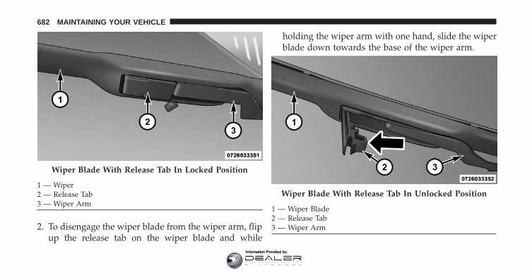
2. To disengage the wiper blade from the wiper arm, flipup the release tab on the wiper blade and while
holding the wiper arm with one hand, slide the wiperblade down towards the base of the wiper arm.
Wiper Blade With Release Tab In Locked Position
1 — Wiper2 — Release Tab3 — Wiper Arm
Wiper Blade With Release Tab In Unlocked Position
1 — Wiper Blade2 — Release Tab3 — Wiper Arm
682 MAINTAINING YOUR VEHICLE
Information Provided by:
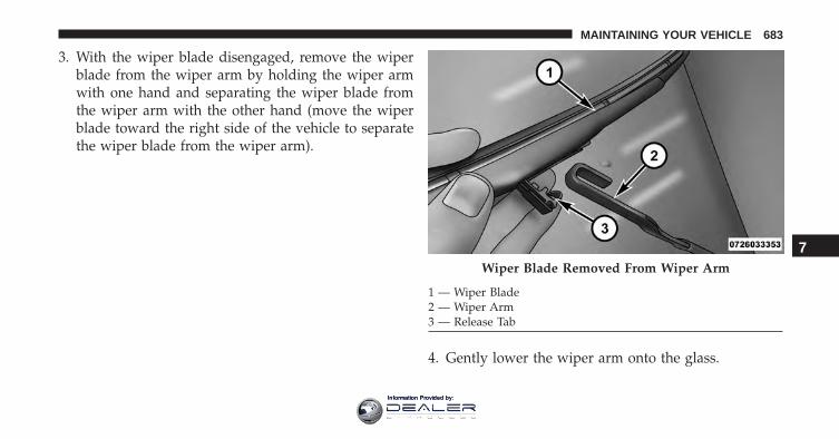
3. With the wiper blade disengaged, remove the wiperblade from the wiper arm by holding the wiper armwith one hand and separating the wiper blade fromthe wiper arm with the other hand (move the wiperblade toward the right side of the vehicle to separatethe wiper blade from the wiper arm).
4. Gently lower the wiper arm onto the glass.
Wiper Blade Removed From Wiper Arm
1 — Wiper Blade2 — Wiper Arm3 — Release Tab
7
MAINTAINING YOUR VEHICLE 683
Information Provided by:
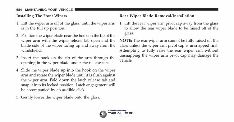
Installing The Front Wipers
1. Lift the wiper arm off of the glass, until the wiper armis in the full up position.
2. Position the wiper blade near the hook on the tip of thewiper arm with the wiper release tab open and theblade side of the wiper facing up and away from thewindshield.
3. Insert the hook on the tip of the arm through theopening in the wiper blade under the release tab.
4. Slide the wiper blade up into the hook on the wiperarm and rotate the wiper blade until it is flush againstthe wiper arm. Fold down the latch release tab andsnap it into its locked position. Latch engagement willbe accompanied by an audible click.
5. Gently lower the wiper blade onto the glass.
Rear Wiper Blade Removal/Installation
1. Lift the rear wiper arm pivot cap away from the glassto allow the rear wiper blade to be raised off of theglass.
NOTE: The rear wiper arm cannot be fully raised off theglass unless the wiper arm pivot cap is unsnapped first.Attempting to fully raise the rear wiper arm withoutunsnapping the wiper arm pivot cap may damage thevehicle.
684 MAINTAINING YOUR VEHICLE
Information Provided by:
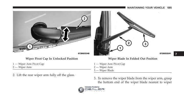
2. Lift the rear wiper arm fully off the glass.3. To remove the wiper blade from the wiper arm, grasp
the bottom end of the wiper blade nearest to wiper
Wiper Pivot Cap In Unlocked Position
1 — Wiper Arm Pivot Cap2 — Wiper Arm
Wiper Blade In Folded Out Position
1 — Wiper Arm Pivot Cap2 — Wiper Arm3 — Wiper Blade
7
MAINTAINING YOUR VEHICLE 685
Information Provided by:
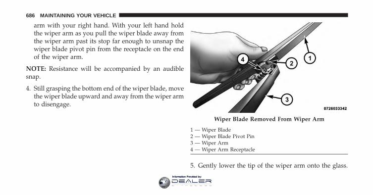
arm with your right hand. With your left hand holdthe wiper arm as you pull the wiper blade away fromthe wiper arm past its stop far enough to unsnap thewiper blade pivot pin from the receptacle on the endof the wiper arm.
NOTE: Resistance will be accompanied by an audiblesnap.
4. Still grasping the bottom end of the wiper blade, movethe wiper blade upward and away from the wiper armto disengage.
5. Gently lower the tip of the wiper arm onto the glass.
Wiper Blade Removed From Wiper Arm
1 — Wiper Blade2 — Wiper Blade Pivot Pin3 — Wiper Arm4 — Wiper Arm Receptacle
686 MAINTAINING YOUR VEHICLE
Information Provided by:
Installing The Rear Wiper
1. Lift the rear wiper arm pivot cap away from the glassto allow the rear wiper blade to be raised off of theglass.
NOTE: The rear wiper arm cannot be fully raised off theglass unless the wiper arm pivot cap is unsnapped first.Attempting to fully raise the rear wiper arm withoutunsnapping the wiper arm pivot cap may damage thevehicle.
2. Lift the rear wiper arm fully off the glass.
3. Insert the wiper blade pivot pin into the opening onthe end of the wiper arm. Grab the bottom end of thewiper arm with one hand, and press the wiper bladeflush with the wiper arm until it snaps into place.
4. Lower the wiper blade onto the glass and snap thewiper arm pivot cap back into place.
Adding Washer Fluid
The windshield and rear window washers share the samefluid reservoir. The fluid reservoir is located in the frontof the engine compartment. Be sure to check the fluidlevel in the reservoir at regular intervals. Fill the reservoirwith windshield washer solvent (not radiator antifreeze)and operate the system for a few seconds to flush out theresidual water.
When refilling the washer fluid reservoir, take somewasher fluid and apply it to a cloth or towel and wipeclean the wiper blades, this will help blade performance.
To prevent freeze-up of your windshield washer systemin cold weather, select a solution or mixture that meets orexceeds the temperature range of your climate. Thisrating information can be found on most washer fluidcontainers.
7
MAINTAINING YOUR VEHICLE 687
Information Provided by:
WARNING!
Commercially available windshield washer solventsare flammable. They could ignite and burn you. Caremust be exercised when filling or working aroundthe washer solution.
Exhaust System
The best protection against carbon monoxide entry intothe vehicle body is a properly maintained engine exhaustsystem.
If you notice a change in the sound of the exhaust system;or if the exhaust fumes can be detected inside the vehicle;or when the underside or rear of the vehicle is damaged;have an authorized technician inspect the complete ex-haust system and adjacent body areas for broken, dam-aged, deteriorated, or mispositioned parts. Open seamsor loose connections could permit exhaust fumes to seepinto the passenger compartment. In addition, have the
exhaust system inspected each time the vehicle is raisedfor lubrication or oil change. Replace as required.
WARNING!
• Exhaust gases can injure or kill. They containcarbon monoxide (CO), which is colorless andodorless. Breathing it can make you unconsciousand can eventually poison you. To avoid breathingCO, refer to “Safety Tips/Exhaust Gas” in “ThingsTo Know Before Starting Your Vehicle” for furtherinformation.
• A hot exhaust system can start a fire if you parkover materials that can burn. Such materials mightbe grass or leaves coming into contact with yourexhaust system. Do not park or operate your ve-hicle in areas where your exhaust system can con-tact anything that can burn.
688 MAINTAINING YOUR VEHICLE
Information Provided by:
CAUTION!
• The catalytic converter requires the use of un-leaded fuel only. Leaded gasoline will destroy theeffectiveness of the catalyst as an emissions controldevice and may seriously reduce engine perfor-mance and cause serious damage to the engine.
• Damage to the catalytic converter can result if yourvehicle is not kept in proper operating condition.In the event of engine malfunction, particularlyinvolving engine misfire or other apparent loss ofperformance, have your vehicle serviced promptly.Continued operation of your vehicle with a severemalfunction could cause the converter to overheat,resulting in possible damage to the converter andvehicle.
Under normal operating conditions, the catalytic con-verter will not require maintenance. However, it is im-portant to keep the engine properly tuned to assureproper catalyst operation and prevent possible catalystdamage.
NOTE: Intentional tampering with emissions controlsystems can result in civil penalties being assessedagainst you.
In unusual situations involving grossly malfunctioningengine operation, a scorching odor may suggest severeand abnormal catalyst overheating. If this occurs, stopthe vehicle, turn off the engine and allow it to cool.Service, including a tune-up to manufacturer’s specifica-tions, should be obtained immediately.
7
MAINTAINING YOUR VEHICLE 689
Information Provided by:
To minimize the possibility of catalytic converter damage:
• Do not shut off the engine or interrupt the ignition,when the transmission is in gear and the vehicle is inmotion.
• Do not try to start the engine by pushing or towing thevehicle.
• Do not idle the engine with any spark plug wiresdisconnected or removed, such as when diagnostictesting, or for prolonged periods during very roughidle or malfunctioning operating conditions.
Cooling System
WARNING!
You or others can be badly burned by hot enginecoolant (antifreeze) or steam from your radiator. If
(Continued)
WARNING! (Continued)you see or hear steam coming from under the hood,do not open the hood until the radiator has had timeto cool. Never try to open a cooling system pressurecap when the radiator or coolant bottle is hot.
Engine Coolant Checks
Check the engine coolant (antifreeze) protection every 12months (before the onset of freezing weather, whereapplicable). If the engine coolant (antifreeze) is dirty, thesystem should be drained, flushed, and refilled withfresh OAT coolant (conforming to MS.90032) by anauthorized dealer. Check the front of the A/C condenserfor any accumulation of bugs, leaves, etc. If dirty, clean bygently spraying water from a garden hose verticallydown the face of the condenser.
690 MAINTAINING YOUR VEHICLE
Information Provided by:
Check the engine cooling system hoses for brittle rubber,cracking, tears, cuts, and tightness of the connection atthe coolant recovery bottle and radiator. Inspect theentire system for leaks.
With the engine at normal operating temperature (butnot running), check the cooling system pressure cap forproper vacuum sealing by draining a small amount ofengine coolant (antifreeze) from the radiator drain cock.If the cap is sealing properly, the engine coolant (anti-freeze) will begin to drain from the coolant recoverybottle. DO NOT REMOVE THE COOLANT PRESSURECAP WHEN THE COOLING SYSTEM IS HOT.
Cooling System — Drain, Flush And Refill
NOTE: Some vehicles require special tools to add coolantproperly. Failure to fill these systems properly could leadto severe internal engine damage. If any coolant isneeded to be added to the system please contact yourlocal authorized dealer.
If the engine coolant (antifreeze) is dirty or containsvisible sediment, have an authorized dealer clean andflush with OAT coolant (antifreeze) (conforming toMS.90032).
Refer to the “Maintenance Schedule” for the propermaintenance intervals.
Selection Of Coolant
Refer to “Fluids, Lubricants, And Genuine Parts” in“Maintaining Your Vehicle” for further information.
CAUTION!
• Mixing of engine coolant (antifreeze) other thanspecified Organic Additive Technology (OAT) en-gine coolant (antifreeze), may result in enginedamage and may decrease corrosion protection.
(Continued)
7
MAINTAINING YOUR VEHICLE 691
Information Provided by:
CAUTION! (Continued)Organic Additive Technology (OAT) engine cool-ant is different and should not be mixed withHybrid Organic Additive Technology (HOAT) en-gine coolant (antifreeze) or any “globally compat-ible” coolant (antifreeze). If a non-OAT enginecoolant (antifreeze) is introduced into the coolingsystem in an emergency, the cooling system willneed to be drained, flushed, and refilled with freshOAT coolant (conforming to MS.90032), by an au-thorized dealer as soon as possible.
• Do not use water alone or alcohol-based enginecoolant (antifreeze) products. Do not use additionalrust inhibitors or antirust products, as they may notbe compatible with the radiator engine coolant andmay plug the radiator.
(Continued)
CAUTION! (Continued)• This vehicle has not been designed for use with
propylene glycol-based engine coolant (antifreeze).Use of propylene glycol-based engine coolant (an-tifreeze) is not recommended.
Adding Coolant
Your vehicle has been built with an improved enginecoolant (OAT coolant conforming to MS.90032) that al-lows extended maintenance intervals. This engine cool-ant (antifreeze) can be used up to ten years or 150,000miles (240,000 km) before replacement. To prevent reduc-ing this extended maintenance period, it is important thatyou use the same engine coolant (OAT coolant conform-ing to MS.90032) throughout the life of your vehicle.
692 MAINTAINING YOUR VEHICLE
Information Provided by:
Please review these recommendations for using OrganicAdditive Technology (OAT) engine coolant (antifreeze)that meets the requirements of FCA Material StandardMS.90032. When adding engine coolant (antifreeze):
• We recommend using MOPAR Antifreeze/Coolant 10Year/150,000 Mile Formula OAT (Organic AdditiveTechnology) that meets the requirements of FCA Ma-terial Standard MS.90032.
• Mix a minimum solution of 50% OAT engine coolantthat meets the requirements of FCA Material StandardMS.90032 and distilled water. Use higher concentra-tions (not to exceed 70%) if temperatures below −34°F(−37°C) are anticipated.
• Use only high purity water such as distilled or deion-ized water when mixing the water/engine coolant(antifreeze) solution. The use of lower quality waterwill reduce the amount of corrosion protection in theengine cooling system.
Please note that it is the owner’s responsibility to main-tain the proper level of protection against freezing ac-cording to the temperatures occurring in the area wherethe vehicle is operated.
NOTE:
• Some vehicles require special tools to add coolantproperly. Failure to fill these systems properly couldlead to severe internal engine damage. If any coolant isneeded to be added to the system, please contact yourlocal authorized dealer.
• Mixing engine coolant (antifreeze) types is not recom-mended and can result in cooling system damage. IfHOAT and OAT coolant are mixed in an emergency,have a authorized dealer drain, flush, and refill withOAT coolant (conforming to MS.90032) as soon aspossible.
7
MAINTAINING YOUR VEHICLE 693
Information Provided by:
Cooling System Pressure Cap
The cap must be fully tightened to prevent loss of enginecoolant (antifreeze), and to ensure that engine coolant(antifreeze) will return to the radiator from the coolantrecovery tank.
The cap should be inspected and cleaned if there is anyaccumulation of foreign material on the sealing surfaces.
WARNING!
• Do not open hot engine cooling system. Never addengine coolant (antifreeze) when the engine isoverheated. Do not loosen or remove the cap to coolan overheated engine. Heat causes pressure tobuild up in the cooling system. To prevent scaldingor injury, do not remove the pressure cap while thesystem is hot or under pressure.
(Continued)
WARNING! (Continued)• Do not use a pressure cap other than the one
specified for your vehicle. Personal injury or en-gine damage may result.
Disposal Of Used Engine Coolant
Used ethylene glycol-based engine coolant (antifreeze) isa regulated substance requiring proper disposal. Checkwith your local authorities to determine the disposalrules for your community. To prevent ingestion by ani-mals or children, do not store ethylene glycol-basedengine coolant in open containers or allow it to remain inpuddles on the ground. If ingested by a child or pet, seekemergency assistance immediately. Clean up any groundspills immediately.
694 MAINTAINING YOUR VEHICLE
Information Provided by:
Coolant Level
The coolant bottle provides a quick visual method fordetermining that the coolant level is adequate. With theengine OFF and cold, the level of the engine coolant(antifreeze) in the bottle should be between the rangesindicated on the bottle.
The radiator normally remains completely full, so there isno need to remove the radiator/coolant pressure capunless checking for engine coolant (antifreeze) freezepoint or replacing coolant. Advise your service attendantof this. As long as the engine operating temperature issatisfactory, the coolant bottle need only be checked oncea month.
When additional engine coolant (antifreeze) is needed tomaintain the proper level, only OAT coolant that meetsthe requirements of FCA Material Standard MS.90032should be added to the coolant bottle. Do not overfill.
Points To Remember
NOTE: When the vehicle is stopped after a few miles/kilometers of operation, you may observe vapor comingfrom the front of the engine compartment. This is nor-mally a result of moisture from rain, snow, or highhumidity accumulating on the radiator and being vapor-ized when the thermostat opens, allowing hot enginecoolant (antifreeze) to enter the radiator.
If an examination of your engine compartment shows noevidence of radiator or hose leaks, the vehicle may besafely driven. The vapor will soon dissipate.
• Do not overfill the coolant expansion bottle.
• Check the coolant freeze point in the radiator and in thecoolant expansion bottle. If engine coolant (antifreeze)needs to be added, the contents of the coolant expansionbottle must also be protected against freezing.
7
MAINTAINING YOUR VEHICLE 695
Information Provided by:
• If frequent engine coolant (antifreeze) additions arerequired, the cooling system should be pressure testedfor leaks.
• Maintain engine coolant (antifreeze) concentration at aminimum of 50% OAT coolant (conforming toMS.90032) and distilled water for proper corrosionprotection of your engine which contains aluminumcomponents.
• Make sure that the coolant expansion bottle overflowhoses are not kinked or obstructed.
• Keep the front of the radiator clean. If your vehicle isequipped with air conditioning, keep the front of thecondenser clean.
• Do not change the thermostat for Summer or Winteroperation. If replacement is ever necessary, install ONLYthe correct type thermostat. Other designs may result inunsatisfactory engine coolant (antifreeze) performance,poor gas mileage, and increased emissions.
Brake System
In order to assure brake system performance, all brakesystem components should be inspected periodically.Refer to the “Maintenance Schedule” for the propermaintenance intervals.
WARNING!
Riding the brakes can lead to brake failure andpossibly a collision. Driving with your foot resting orriding on the brake pedal can result in abnormallyhigh brake temperatures, excessive lining wear, andpossible brake damage. You would not have your fullbraking capacity in an emergency.
Brake Master Cylinder
The fluid in the master cylinder should be checked whenperforming under hood services or immediately if the“Brake Warning Light” is illuminated.
696 MAINTAINING YOUR VEHICLE
Information Provided by:
Be sure to clean the top of the master cylinder area beforeremoving the cap. If necessary, add fluid to bring thefluid level up to the requirements described on the brakefluid reservoir. With disc brakes, fluid level can beexpected to fall as the brake pads wear. Brake fluid levelshould be checked when pads are replaced. However,low fluid level may be caused by a leak and a checkupmay be needed.
Use only manufacturer’s recommended brake fluid. Re-fer to “Fluids, Lubricants, And Genuine Parts” in “Main-taining Your Vehicle” for further information.
WARNING!
• Use only manufacturer’s recommended brakefluid. Refer to “Fluids, Lubricants, And GenuineParts” in “Maintaining Your Vehicle” for furtherinformation. Using the wrong type of brake fluid
(Continued)
WARNING! (Continued)can severely damage your brake system and/orimpair its performance. The proper type of brakefluid for your vehicle is also identified on theoriginal factory installed hydraulic master cylinderreservoir.
• To avoid contamination from foreign matter ormoisture, use only new brake fluid or fluid that hasbeen in a tightly closed container. Keep the mastercylinder reservoir cap secured at all times. Brakefluid in a open container absorbs moisture from theair resulting in a lower boiling point. This maycause it to boil unexpectedly during hard or pro-longed braking, resulting in sudden brake failure.This could result in a collision.
• Overfilling the brake fluid reservoir can result inspilling brake fluid on hot engine parts, causing
(Continued)
7
MAINTAINING YOUR VEHICLE 697
Information Provided by:
WARNING! (Continued)the brake fluid to catch fire. Brake fluid can alsodamage painted and vinyl surfaces, care should betaken to avoid its contact with these surfaces.
• Do not allow petroleum based fluid to contaminatethe brake fluid. Brake seal components could bedamaged, causing partial or complete brake failure.This could result in a collision.
Automatic Transmission
Selection Of Lubricant
It is important to use the proper transmission fluid toensure optimum transmission performance and life. Useonly the manufacturer’s specified transmission fluid.Refer to “Fluids, Lubricants, And Genuine Parts” in thissection for fluid specifications. It is important to maintainthe transmission fluid at the correct level using therecommended fluid.
NOTE: No chemical flushes should be used in anytransmission; only the approved lubricant should beused.
CAUTION!
Using a transmission fluid other than the manufac-turer’s recommended fluid may cause deteriorationin transmission shift quality and/or torque convertershudder. Refer to “Fluids, Lubricants, And GenuineParts” in this section for fluid specifications.
Special Additives
The manufacturer strongly recommends against usingany special additives in the transmission. AutomaticTransmission Fluid (ATF) is an engineered product andits performance may be impaired by supplemental addi-tives. Therefore, do not add any fluid additives to the
698 MAINTAINING YOUR VEHICLE
Information Provided by:
transmission. Avoid using transmission sealers as theymay adversely affect seals.
CAUTION!
Do not use chemical flushes in your transmission asthe chemicals can damage your transmission compo-nents. Such damage is not covered by the NewVehicle Limited Warranty.
Fluid Level Check
The fluid level is preset at the factory and does notrequire adjustment under normal operating conditions.Routine fluid level checks are not required, therefore thetransmission has no dipstick. Your authorized dealer cancheck your transmission fluid level using special servicetools. If you notice fluid leakage or transmission malfunc-tion, visit your authorized dealer immediately to have
the transmission fluid level checked. Operating the ve-hicle with an improper fluid level can cause severetransmission damage.
CAUTION!
If a transmission fluid leak occurs, visit your autho-rized dealer immediately. Severe transmission dam-age may occur. Your authorized dealer has the propertools to adjust the fluid level accurately.
Fluid And Filter Changes
Under normal operating conditions, the fluid installed atthe factory will provide satisfactory lubrication for thelife of the vehicle.
Routine fluid and filter changes are not required. How-ever, change the fluid and filter if the fluid becomescontaminated (with water, etc.), or if the transmission isdisassembled for any reason.
7
MAINTAINING YOUR VEHICLE 699
Information Provided by:
Appearance Care And Protection From Corrosion
Protection Of Body And Paint From Corrosion
Vehicle body care requirements vary according to geo-graphic locations and usage. Chemicals that make roadspassable in snow and ice and those that are sprayed ontrees and road surfaces during other seasons are highlycorrosive to the metal in your vehicle. Outside parking,which exposes your vehicle to airborne contaminants,road surfaces on which the vehicle is operated, extremehot or cold weather and other extreme conditions willhave an adverse effect on paint, metal trim, and under-body protection.
The following maintenance recommendations will enableyou to obtain maximum benefit from the corrosionresistance built into your vehicle.
What Causes Corrosion?
Corrosion is the result of deterioration or removal ofpaint and protective coatings from your vehicle.
The most common causes are:
• Road salt, dirt and moisture accumulation.
• Stone and gravel impact.
• Insects, tree sap and tar.
• Salt in the air near seacoast localities.
• Atmospheric fallout/industrial pollutants.
Washing
• Wash your vehicle regularly. Always wash your ve-hicle in the shade using MOPAR Car Wash, or a mildcar wash soap, and rinse the panels completely withclear water.
700 MAINTAINING YOUR VEHICLE
Information Provided by:
• If insects, tar, or other similar deposits have accumu-lated on your vehicle, use MOPAR Super Kleen Bugand Tar Remover to remove.
• Use a high quality cleaner wax, such as MOPARCleaner Wax to remove road film, stains and to protectyour paint finish. Take care never to scratch the paint.
• Avoid using abrasive compounds and power buffingthat may diminish the gloss or thin out the paint finish.
CAUTION!
• Do not use abrasive or strong cleaning materialssuch as steel wool or scouring powder that willscratch metal and painted surfaces.
• Use of power washers exceeding 1,200 psi (8 274kPa) can result in damage or removal of paint anddecals.
Special Care
• If you drive on salted or dusty roads or if you drivenear the ocean, hose off the undercarriage at least oncea month.
• It is important that the drain holes in the lower edgesof the doors, rocker panels, and trunk be kept clear andopen.
• If you detect any stone chips or scratches in the paint,touch them up immediately. The cost of such repairs isconsidered the responsibility of the owner.
• If your vehicle is damaged due to a collision or similarcause that destroys the paint and protective coating,have your vehicle repaired as soon as possible. Thecost of such repairs is considered the responsibility ofthe owner.
7
MAINTAINING YOUR VEHICLE 701
Information Provided by:
• If you carry special cargo such as chemicals, fertilizers,de-icer salt, etc., be sure that such materials are wellpackaged and sealed.
• If a lot of driving is done on gravel roads, considermud or stone shields behind each wheel.
• Use MOPAR Touch Up Paint on scratches as soon aspossible. Your authorized dealer has touch up paint tomatch the color of your vehicle.
Wheel And Wheel Trim Care
• All wheels and wheel trim, especially aluminum andchrome plated wheels, should be cleaned regularlywith a mild soap and water to prevent corrosion.
• To remove heavy soil and/or excessive brake dust, useMOPAR Wheel Cleaner.
NOTE: If your vehicle is equipped with Dark Vapor orBlack Satin Chrome wheels DO NOT USE wheel cleaners,abrasives or polishing compounds. They will perma-nently damage this finish and such damage is not cov-ered by the New Vehicle Limited Warranty. USE ONLYMILD SOAP AND WATER WITH A SOFT CLOTH. Usedon a regular basis this is all that is required to maintainthis finish.
CAUTION!
Do not use scouring pads, steel wool, a bristle brush,or metal polishes. Do not use oven cleaner. Theseproducts may damage the wheel’s protective finish.Avoid automatic car washes that use acidic solutionsor harsh brushes that may damage the wheel’s pro-tective finish. Only MOPAR Wheel Cleaner orequivalent is recommended.
702 MAINTAINING YOUR VEHICLE
Information Provided by:

Stain Repel Fabric Cleaning Procedure — IfEquipped
Stain Repel seats may be cleaned in the following man-ner:
• Remove as much of the stain as possible by blottingwith a clean, dry towel.
• Blot any remaining stain with a clean, damp towel.
• For tough stains, apply MOPAR Total Clean, or a mildsoap solution to a clean, damp cloth and remove stain.Use a fresh, damp towel to remove soap residue.
• For grease stains, apply MOPAR Multi-PurposeCleaner to a clean, damp cloth and remove stain. Usea fresh, damp towel to remove soap residue.
• Do not use any harsh solvents or any other form ofprotectants on Stain Repel products.
Interior Care
Use MOPAR Total Clean to clean fabric upholstery andcarpeting.
Use MOPAR Total Clean to clean vinyl upholstery.
MOPAR Total Clean is specifically recommended forleather upholstery.
Your leather upholstery can be best preserved by regularcleaning with a damp soft cloth. Small particles of dirtcan act as an abrasive and damage the leather upholsteryand should be removed promptly with a damp cloth.Stubborn soils can be removed easily with a soft clothand MOPAR Total Clean. Care should be taken to avoidsoaking your leather upholstery with any liquid. Pleasedo not use polishes, oils, cleaning fluids, solvents, deter-gents, or ammonia-based cleaners to clean your leatherupholstery. Application of a leather conditioner is notrequired to maintain the original condition.
7
MAINTAINING YOUR VEHICLE 703
Information Provided by:
WARNING!
Do not use volatile solvents for cleaning purposes.Many are potentially flammable, and if used inclosed areas they may cause respiratory harm.
CAUTION!
Direct contact of air fresheners, insect repellents,suntan lotions, or hand sanitizers to the plastic,painted, or decorated surfaces of the interior maycause permanent damage. Wipe away immediately.
CAUTION!
Damage caused by these type of products may not becovered by your New Vehicle Limited Warranty.
CAUTION!
Do not use Alcohol and Alcohol-based and/or Ketonbased cleaning products to clean leather seats, asdamage to the seat may result.
Cleaning Headlights
Your vehicle is equipped with plastic headlights and foglights that are lighter and less susceptible to stone break-age than glass headlights.
Plastic is not as scratch resistant as glass and thereforedifferent lens cleaning procedures must be followed.
To minimize the possibility of scratching the lenses andreducing light output, avoid wiping with a dry cloth. Toremove road dirt, wash with a mild soap solution fol-lowed by rinsing.
Do not use abrasive cleaning components, solvents, steelwool or other aggressive material to clean the lenses.
704 MAINTAINING YOUR VEHICLE
Information Provided by:
Glass Surfaces
All glass surfaces should be cleaned on a regular basiswith MOPAR Glass Cleaner, or any commercialhousehold-type glass cleaner. Never use an abrasive typecleaner. Use caution when cleaning the inside rear win-dow equipped with electric defrosters or windowsequipped with radio antennas. Do not use scrapers orother sharp instrument that may scratch the elements.
When cleaning the rear view mirror, spray cleaner on thetowel or cloth that you are using. Do not spray cleanerdirectly on the mirror.
Cleaning Plastic Instrument Cluster Lenses
The lenses in front of the instruments in this vehicle aremolded in clear plastic. When cleaning the lenses, caremust be taken to avoid scratching the plastic.
1. Clean with a wet soft cloth. A mild soap solution maybe used, but do not use high alcohol content orabrasive cleaners. If soap is used, wipe clean with aclean damp cloth.
2. Dry with a soft cloth.
Seat Belt Maintenance
Do not bleach, dye or clean the belts with chemicalsolvents or abrasive cleaners. This will weaken the fabric.Sun damage can also weaken the fabric.
If the belts need cleaning, use a mild soap solution orlukewarm water. Do not remove the belts from thevehicle to wash them. Dry with a soft cloth.
Replace the belts if they appear frayed or worn or if thebuckles do not work properly.
7
MAINTAINING YOUR VEHICLE 705
Information Provided by:
WARNING!
A frayed or torn belt could rip apart in a collision andleave you with no protection. Inspect the belt systemperiodically, checking for cuts, frays, or loose parts.Damaged parts must be replaced immediately. Donot disassemble or modify the system. Seat beltassemblies must be replaced after a collision if theyhave been damaged (i.e., bent retractor, torn web-bing, etc.).
FUSES
WARNING!
• When replacing a blown fuse, always use an appro-priate replacement fuse with the same amp rating asthe original fuse. Never replace a fuse with another
(Continued)
WARNING! (Continued)fuse of higher amp rating. Never replace a blownfuse with metal wires or any other material. Failureto use proper fuses may result in serious personalinjury, fire and/or property damage.
• Before replacing a fuse, make sure that the ignitionis off and that all the other services are switched offand/or disengaged.
• If the replaced fuse blows again, contact an autho-rized dealer.
• If a general protection fuse for safety systems (airbag system, braking system), power unit systems(engine system, gearbox system) or steering systemblows, contact an authorized dealer.
706 MAINTAINING YOUR VEHICLE
Information Provided by:
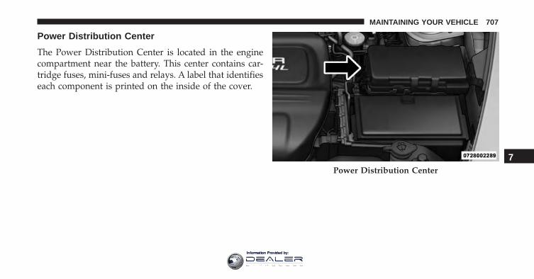
Power Distribution Center
The Power Distribution Center is located in the enginecompartment near the battery. This center contains car-tridge fuses, mini-fuses and relays. A label that identifieseach component is printed on the inside of the cover.
Power Distribution Center
7
MAINTAINING YOUR VEHICLE 707
Information Provided by:
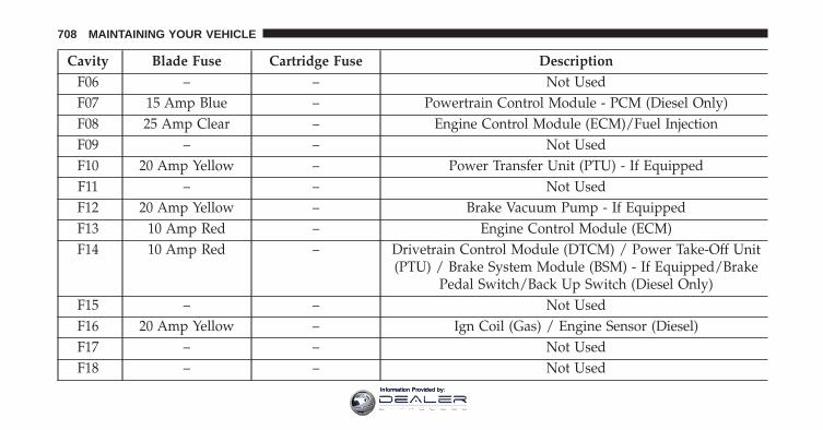
Cavity Blade Fuse Cartridge Fuse DescriptionF06 – – Not UsedF07 15 Amp Blue – Powertrain Control Module - PCM (Diesel Only)F08 25 Amp Clear – Engine Control Module (ECM)/Fuel InjectionF09 – – Not UsedF10 20 Amp Yellow – Power Transfer Unit (PTU) - If EquippedF11 – – Not UsedF12 20 Amp Yellow – Brake Vacuum Pump - If EquippedF13 10 Amp Red – Engine Control Module (ECM)F14 10 Amp Red – Drivetrain Control Module (DTCM) / Power Take-Off Unit
(PTU) / Brake System Module (BSM) - If Equipped/BrakePedal Switch/Back Up Switch (Diesel Only)
F15 – – Not UsedF16 20 Amp Yellow – Ign Coil (Gas) / Engine Sensor (Diesel)F17 – – Not UsedF18 – – Not Used
708 MAINTAINING YOUR VEHICLE
Information Provided by:
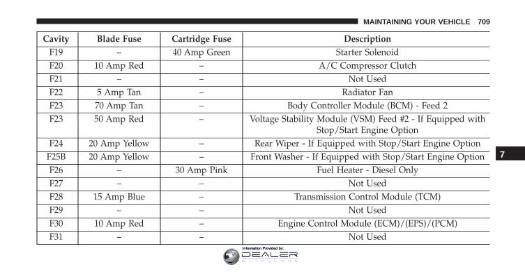
Cavity Blade Fuse Cartridge Fuse DescriptionF19 – 40 Amp Green Starter SolenoidF20 10 Amp Red – A/C Compressor ClutchF21 – – Not UsedF22 5 Amp Tan – Radiator FanF23 70 Amp Tan – Body Controller Module (BCM) - Feed 2F23 50 Amp Red – Voltage Stability Module (VSM) Feed #2 - If Equipped with
Stop/Start Engine OptionF24 20 Amp Yellow – Rear Wiper - If Equipped with Stop/Start Engine Option
F25B 20 Amp Yellow – Front Washer - If Equipped with Stop/Start Engine OptionF26 – 30 Amp Pink Fuel Heater - Diesel OnlyF27 – – Not UsedF28 15 Amp Blue – Transmission Control Module (TCM)F29 – – Not UsedF30 10 Amp Red – Engine Control Module (ECM)/(EPS)/(PCM)F31 – – Not Used
7
MAINTAINING YOUR VEHICLE 709
Information Provided by:
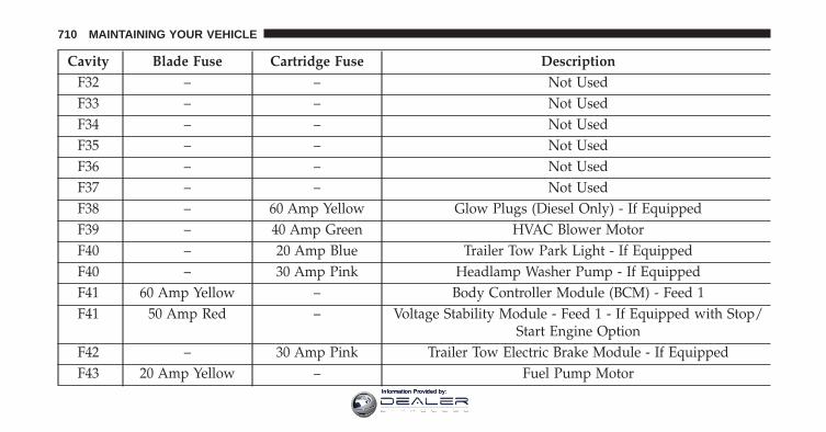
Cavity Blade Fuse Cartridge Fuse DescriptionF32 – – Not UsedF33 – – Not UsedF34 – – Not UsedF35 – – Not UsedF36 – – Not UsedF37 – – Not UsedF38 – 60 Amp Yellow Glow Plugs (Diesel Only) - If EquippedF39 – 40 Amp Green HVAC Blower MotorF40 – 20 Amp Blue Trailer Tow Park Light - If EquippedF40 – 30 Amp Pink Headlamp Washer Pump - If EquippedF41 60 Amp Yellow – Body Controller Module (BCM) - Feed 1F41 50 Amp Red – Voltage Stability Module - Feed 1 - If Equipped with Stop/
Start Engine OptionF42 – 30 Amp Pink Trailer Tow Electric Brake Module - If EquippedF43 20 Amp Yellow – Fuel Pump Motor
710 MAINTAINING YOUR VEHICLE
Information Provided by:
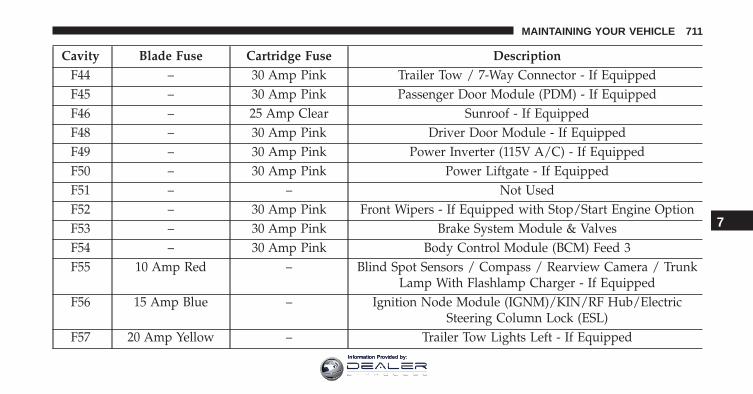
Cavity Blade Fuse Cartridge Fuse DescriptionF44 – 30 Amp Pink Trailer Tow / 7-Way Connector - If EquippedF45 – 30 Amp Pink Passenger Door Module (PDM) - If EquippedF46 – 25 Amp Clear Sunroof - If EquippedF48 – 30 Amp Pink Driver Door Module - If EquippedF49 – 30 Amp Pink Power Inverter (115V A/C) - If EquippedF50 – 30 Amp Pink Power Liftgate - If EquippedF51 – – Not UsedF52 – 30 Amp Pink Front Wipers - If Equipped with Stop/Start Engine OptionF53 – 30 Amp Pink Brake System Module & ValvesF54 – 30 Amp Pink Body Control Module (BCM) Feed 3F55 10 Amp Red – Blind Spot Sensors / Compass / Rearview Camera / Trunk
Lamp With Flashlamp Charger - If EquippedF56 15 Amp Blue – Ignition Node Module (IGNM)/KIN/RF Hub/Electric
Steering Column Lock (ESL)F57 20 Amp Yellow – Trailer Tow Lights Left - If Equipped
7
MAINTAINING YOUR VEHICLE 711
Information Provided by:
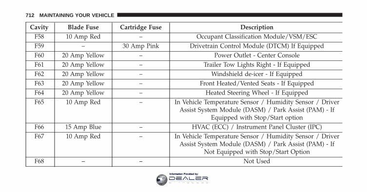
Cavity Blade Fuse Cartridge Fuse DescriptionF58 10 Amp Red – Occupant Classification Module/VSM/ESCF59 – 30 Amp Pink Drivetrain Control Module (DTCM) If EquippedF60 20 Amp Yellow – Power Outlet - Center ConsoleF61 20 Amp Yellow – Trailer Tow Lights Right - If EquippedF62 20 Amp Yellow – Windshield de-icer - If EquippedF63 20 Amp Yellow – Front Heated/Vented Seats - If EquippedF64 20 Amp Yellow – Heated Steering Wheel - If EquippedF65 10 Amp Red – In Vehicle Temperature Sensor / Humidity Sensor / Driver
Assist System Module (DASM) / Park Assist (PAM) - IfEquipped with Stop/Start option
F66 15 Amp Blue – HVAC (ECC) / Instrument Panel Cluster (IPC)F67 10 Amp Red – In Vehicle Temperature Sensor / Humidity Sensor / Driver
Assist System Module (DASM) / Park Assist (PAM) - IfNot Equipped with Stop/Start Option
F68 – – Not Used
712 MAINTAINING YOUR VEHICLE
Information Provided by:
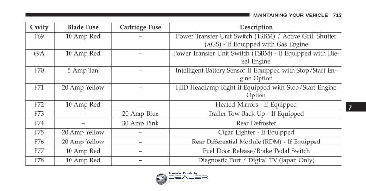
Cavity Blade Fuse Cartridge Fuse DescriptionF69 10 Amp Red – Power Transfer Unit Switch (TSBM) / Active Grill Shutter
(AGS) - If Equipped with Gas Engine69A 10 Amp Red – Power Transfer Unit Switch (TSBM) - If Equipped with Die-
sel EngineF70 5 Amp Tan – Intelligent Battery Sensor If Equipped with Stop/Start En-
gine OptionF71 20 Amp Yellow – HID Headlamp Right if Equipped with Stop/Start Engine
OptionF72 10 Amp Red – Heated Mirrors - If EquippedF73 – 20 Amp Blue Trailer Tow Back Up - If EquippedF74 – 30 Amp Pink Rear DefrosterF75 20 Amp Yellow – Cigar Lighter - If EquippedF76 20 Amp Yellow – Rear Differential Module (RDM) - If EquippedF77 10 Amp Red – Fuel Door Release/Brake Pedal SwitchF78 10 Amp Red – Diagnostic Port / Digital TV (Japan Only)
7
MAINTAINING YOUR VEHICLE 713
Information Provided by:
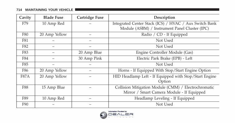
Cavity Blade Fuse Cartridge Fuse DescriptionF79 10 Amp Red – Integrated Center Stack (ICS) / HVAC / Aux Switch Bank
Module (ASBM) / Instrument Panel Cluster (IPC)F80 20 Amp Yellow – Radio / CD - If EquippedF81 – – Not UsedF82 – – Not UsedF83 – 20 Amp Blue Engine Controller Module (Gas)F84 – 30 Amp Pink Electric Park Brake (EPB) - LeftF85 – – Not UsedF86 20 Amp Yellow – Horns - If Equipped With Stop/Start Engine Option
F87A 20 Amp Yellow – HID Headlamp Left - If Equipped with Stop/Start EngineOption
F88 15 Amp Blue – Collision Mitigation Module (CMM) / ElectrochromaticMirror / Smart Camera Module - If Equipped
F89 10 Amp Red – Headlamp Leveling - If EquippedF90 – – Not Used
714 MAINTAINING YOUR VEHICLE
Information Provided by:
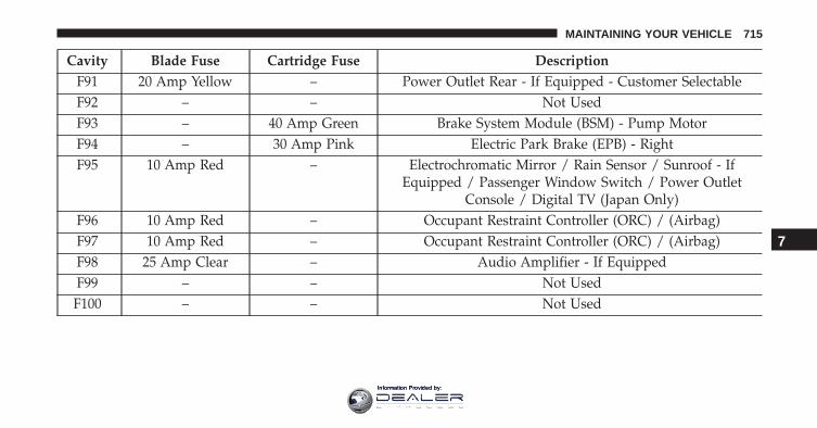
Cavity Blade Fuse Cartridge Fuse DescriptionF91 20 Amp Yellow – Power Outlet Rear - If Equipped - Customer SelectableF92 – – Not UsedF93 – 40 Amp Green Brake System Module (BSM) - Pump MotorF94 – 30 Amp Pink Electric Park Brake (EPB) - RightF95 10 Amp Red – Electrochromatic Mirror / Rain Sensor / Sunroof - If
Equipped / Passenger Window Switch / Power OutletConsole / Digital TV (Japan Only)
F96 10 Amp Red – Occupant Restraint Controller (ORC) / (Airbag)F97 10 Amp Red – Occupant Restraint Controller (ORC) / (Airbag)F98 25 Amp Clear – Audio Amplifier - If EquippedF99 – – Not UsedF100 – – Not Used
7
MAINTAINING YOUR VEHICLE 715
Information Provided by:
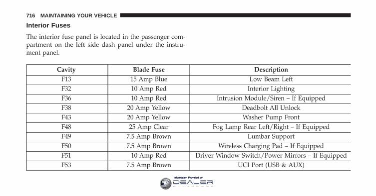
Interior Fuses
The interior fuse panel is located in the passenger com-partment on the left side dash panel under the instru-ment panel.
Cavity Blade Fuse DescriptionF13 15 Amp Blue Low Beam LeftF32 10 Amp Red Interior LightingF36 10 Amp Red Intrusion Module/Siren – If EquippedF38 20 Amp Yellow Deadbolt All UnlockF43 20 Amp Yellow Washer Pump FrontF48 25 Amp Clear Fog Lamp Rear Left/Right – If EquippedF49 7.5 Amp Brown Lumbar SupportF50 7.5 Amp Brown Wireless Charging Pad – If EquippedF51 10 Amp Red Driver Window Switch/Power Mirrors – If EquippedF53 7.5 Amp Brown UCI Port (USB & AUX)
716 MAINTAINING YOUR VEHICLE
Information Provided by:
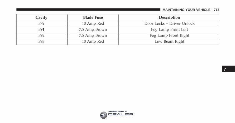
Cavity Blade Fuse DescriptionF89 10 Amp Red Door Locks – Driver UnlockF91 7.5 Amp Brown Fog Lamp Front LeftF92 7.5 Amp Brown Fog Lamp Front RightF93 10 Amp Red Low Beam Right
7
MAINTAINING YOUR VEHICLE 717
Information Provided by:
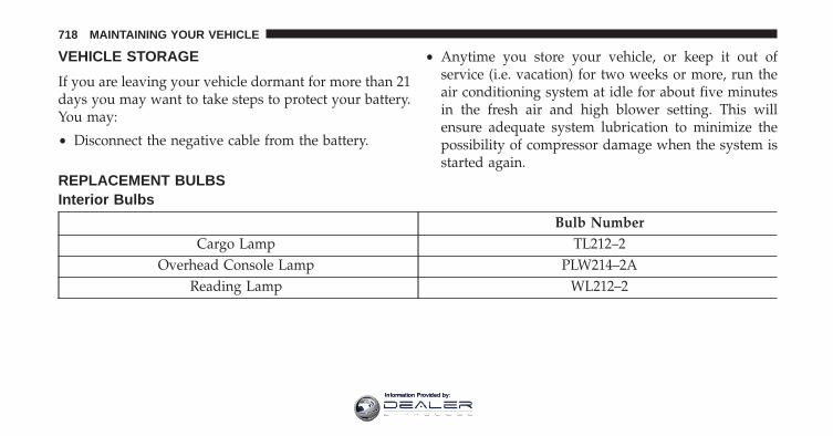
VEHICLE STORAGE
If you are leaving your vehicle dormant for more than 21days you may want to take steps to protect your battery.You may:
• Disconnect the negative cable from the battery.
• Anytime you store your vehicle, or keep it out ofservice (i.e. vacation) for two weeks or more, run theair conditioning system at idle for about five minutesin the fresh air and high blower setting. This willensure adequate system lubrication to minimize thepossibility of compressor damage when the system isstarted again.
REPLACEMENT BULBSInterior Bulbs
Bulb NumberCargo Lamp TL212–2
Overhead Console Lamp PLW214–2AReading Lamp WL212–2
718 MAINTAINING YOUR VEHICLE
Information Provided by:
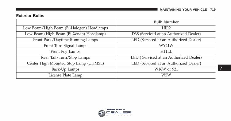
Exterior Bulbs
Bulb NumberLow Beam/High Beam (Bi-Halogen) Headlamps HIR2Low Beam/High Beam (Bi-Xenon) Headlamps D3S (Serviced at an Authorized Dealer)
Front Park/Daytime Running Lamps LED (Serviced at an Authorized Dealer)Front Turn Signal Lamps WY21W
Front Fog Lamps H11LLRear Tail/Turn/Stop Lamps LED ( Serviced at an Authorized Dealer)
Center High Mounted Stop Lamp (CHMSL) LED (Serviced at an Authorized Dealer)Back-Up Lamps W16W or 921
License Plate Lamp W5W
7
MAINTAINING YOUR VEHICLE 719
Information Provided by:
BULB REPLACEMENT
NOTE: Lens fogging can occur under certain atmo-spheric conditions. This will usually clear as atmosphericconditions change to allow the condensation to changeback into a vapor. Turning the lamps on will usuallyaccelerate the clearing process.
Low Beam And High Beam Headlamps
Bi-Xenon High Intensity Discharge (HID)Headlamps — If Equipped
The headlamps contain a type of high voltage dischargelight source. High voltage can remain in the circuit evenwith the headlamp switch off. Because of this, you shouldnot attempt to service a HID headlamp light sourceyourself. If an HID headlamp light source fails, take yourvehicle to an authorized dealer for service.
NOTE: On vehicles equipped with HID headlamps,when the headlamps are turned on, there is a blue hue tothe lights. This diminishes and becomes more white afterapproximately 10 seconds, as the system charges.
WARNING!
A transient high voltage occurs at the bulb sockets ofHID headlamps when the headlamp switch is turnedON. It may cause serious electrical shock or electro-cution if not serviced properly. See your authorizeddealer for service.
Bi-Halogen Headlamps
1. Remove the 3 hex head screws from the wheel liner.
2. Pull the exterior edge of the liner towards the tire togain access to the headlamp bulb cap.
720 MAINTAINING YOUR VEHICLE
Information Provided by:
3. Firmly grasp the cap and rotate it counterclockwise tounlock it.
4. Firmly grasp the bulb and connector assembly androtate counterclockwise to remove from the housing.
5. Disconnect the bulb from the electrical connector andthen connect the replacement bulb.
CAUTION!
Do not touch the new bulb with your fingers. Oilcontamination will severely shorten bulb life. If thebulb comes in contact with any oily surface, clean thebulb with rubbing alcohol.
6. Install the bulb and connector assembly into theheadlamp housing and rotate clockwise to lock it inplace.
7. Install the bulb cap in the headlamp housing androtate clockwise to lock it in place.
8. Install the 3 hex head screws into the wheel liner.
Front Turn Signals And Front Side Marker Lamps
1. Open the hood.
NOTE: Removal of the air cleaner filter housing may benecessary prior to replacing bulbs in the upper lampassembly on the passenger side of the vehicle.
2. Twist the appropriate bulb and socket assembly coun-terclockwise, and then remove the bulb and socketassembly from the lamp housing.
3. Pull the bulb out of the socket and insert the replace-ment bulb.
4. Install the bulb and socket assembly into the housing,and rotate the socket clockwise to lock it in place.
7
MAINTAINING YOUR VEHICLE 721
Information Provided by:
5. Re-install air cleaner filter housing if removed.
Front Fog Lamp
1. Remove the 3 hex head screws from the wheel liner.
2. Pull the exterior edge of the liner towards the tire togain access to the bulb.
3. Rotate the bulb’s socket counterclockwise, and removethe bulb and socket assembly from the fog lamphousing.
4. Pull the bulb out of the socket and insert the replace-ment bulb.
CAUTION!
Do not touch the new bulb with your fingers. Oilcontamination will severely shorten bulb life. If thebulb comes in contact with any oily surface, clean thebulb with rubbing alcohol.
5. Install the bulb and socket assembly into the into thefog lamp housing, and rotate the connector clockwiseto lock it in place.
6. Install the 3 hex head screws into the wheel liner.
Front Fog Lamp (Trailhawk)
1. Unlock lower access door in wheel liner.
2. Reach behind the fog lamp housing to access the bulb.
3. Squeeze the two tabs on the side of the bulb socket andpull straight out from the fog lamp.
4. Disconnect the wire harness from the bulb.
722 MAINTAINING YOUR VEHICLE
Information Provided by:
CAUTION!
Do not touch the new bulb with your fingers. Oilcontamination will severely shorten bulb life. If thebulb comes in contact with any oily surface, clean thebulb with rubbing alcohol.
5. Reconnect the wiring harness to the new bulb andreinstall by inserting the new bulb straight into the foglamp housing until it locks in place.
6. Lock the lower door in the wheel liner.
Bodyside Mounted Back-up Lamp
1. Open the liftgate.
2. Remove the screws that fasten the tail lamp housing tothe vehicle.
3. Grasp the tail lamp and pull firmly rearward todisengage the lamp from the vehicle.
4. Disconnect the electrical connector.
5. Twist the socket counterclockwise and remove fromhousing.
6. Pull the bulb to remove it from the socket.
7. Replace the bulb and install the socket.
8. Reconnect the electrical connector.
9. Reinstall the tail lamp housing and screws.
10. Close the liftgate.
Liftgate Mounted Back-up Lamp
1. Open the liftgate.
2. Use a fiber stick or flat blade screw driver to pry thelower trim from the liftgate.
3. Once the trim is loose, pull it back exposing the trimpanel.
7
MAINTAINING YOUR VEHICLE 723
Information Provided by:
4. Using a fiber stick or flat blade screw driver, open thetrim panel exposing the back of the liftgate lamp.
5. Disconnect the electrical connector.
6. Twist the socket counterclockwise and remove fromlamp.
7. Pull the bulb to remove it from the socket.
8. Replace the bulb, reinstall the socket.
9. Connect the electrical connector.
10. Reinstall the trim panel and the lower trim.
11. Close the liftgate.
License Plate Lamp
1. Using a small screwdriver, press inward the lockingtab on the side of the lamp assembly and pull down onthe lamp assembly for removal.
2. Pull bulb from socket, replace, and reinstall the lampassembly into place ensuring the locking tab is secure.
724 MAINTAINING YOUR VEHICLE
Information Provided by:
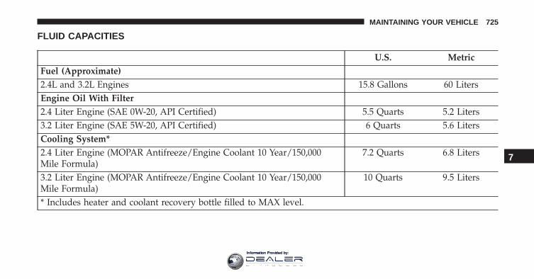
FLUID CAPACITIES
U.S. MetricFuel (Approximate)2.4L and 3.2L Engines 15.8 Gallons 60 LitersEngine Oil With Filter2.4 Liter Engine (SAE 0W-20, API Certified) 5.5 Quarts 5.2 Liters3.2 Liter Engine (SAE 5W-20, API Certified) 6 Quarts 5.6 LitersCooling System*2.4 Liter Engine (MOPAR Antifreeze/Engine Coolant 10 Year/150,000Mile Formula)
7.2 Quarts 6.8 Liters
3.2 Liter Engine (MOPAR Antifreeze/Engine Coolant 10 Year/150,000Mile Formula)
10 Quarts 9.5 Liters
* Includes heater and coolant recovery bottle filled to MAX level.
7
MAINTAINING YOUR VEHICLE 725
Information Provided by:
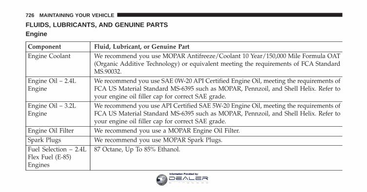
FLUIDS, LUBRICANTS, AND GENUINE PARTSEngine
Component Fluid, Lubricant, or Genuine PartEngine Coolant We recommend you use MOPAR Antifreeze/Coolant 10 Year/150,000 Mile Formula OAT
(Organic Additive Technology) or equivalent meeting the requirements of FCA StandardMS.90032.
Engine Oil – 2.4LEngine
We recommend you use SAE 0W-20 API Certified Engine Oil, meeting the requirements ofFCA US Material Standard MS-6395 such as MOPAR, Pennzoil, and Shell Helix. Refer toyour engine oil filler cap for correct SAE grade.
Engine Oil – 3.2LEngine
We recommend you use API Certified SAE 5W-20 Engine Oil, meeting the requirements ofFCA US Material Standard MS-6395 such as MOPAR, Pennzoil, and Shell Helix. Refer toyour engine oil filler cap for correct SAE grade.
Engine Oil Filter We recommend you use a MOPAR Engine Oil Filter.Spark Plugs We recommend you use MOPAR Spark Plugs.Fuel Selection – 2.4LFlex Fuel (E-85)Engines
87 Octane, Up To 85% Ethanol.
726 MAINTAINING YOUR VEHICLE
Information Provided by:
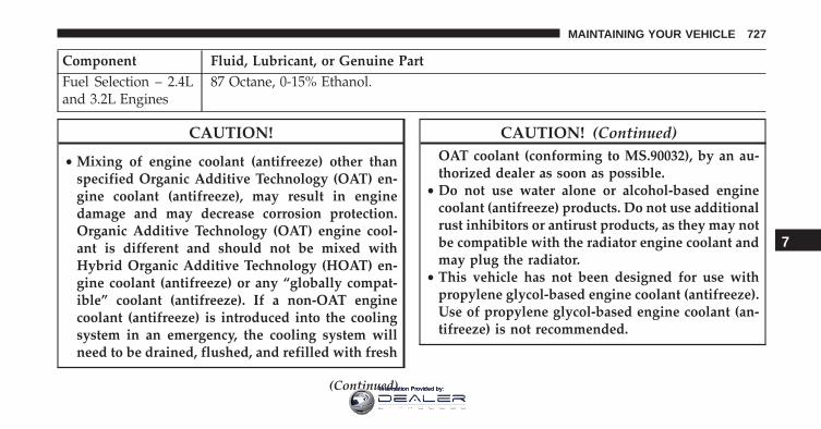
Component Fluid, Lubricant, or Genuine PartFuel Selection – 2.4Land 3.2L Engines
87 Octane, 0-15% Ethanol.
CAUTION!
• Mixing of engine coolant (antifreeze) other thanspecified Organic Additive Technology (OAT) en-gine coolant (antifreeze), may result in enginedamage and may decrease corrosion protection.Organic Additive Technology (OAT) engine cool-ant is different and should not be mixed withHybrid Organic Additive Technology (HOAT) en-gine coolant (antifreeze) or any “globally compat-ible” coolant (antifreeze). If a non-OAT enginecoolant (antifreeze) is introduced into the coolingsystem in an emergency, the cooling system willneed to be drained, flushed, and refilled with fresh
(Continued)
CAUTION! (Continued)OAT coolant (conforming to MS.90032), by an au-thorized dealer as soon as possible.
• Do not use water alone or alcohol-based enginecoolant (antifreeze) products. Do not use additionalrust inhibitors or antirust products, as they may notbe compatible with the radiator engine coolant andmay plug the radiator.
• This vehicle has not been designed for use withpropylene glycol-based engine coolant (antifreeze).Use of propylene glycol-based engine coolant (an-tifreeze) is not recommended.
7
MAINTAINING YOUR VEHICLE 727
Information Provided by:
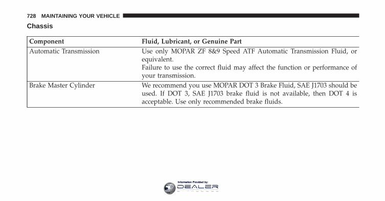
Chassis
Component Fluid, Lubricant, or Genuine PartAutomatic Transmission Use only MOPAR ZF 8&9 Speed ATF Automatic Transmission Fluid, or
equivalent.Failure to use the correct fluid may affect the function or performance ofyour transmission.
Brake Master Cylinder We recommend you use MOPAR DOT 3 Brake Fluid, SAE J1703 should beused. If DOT 3, SAE J1703 brake fluid is not available, then DOT 4 isacceptable. Use only recommended brake fluids.
728 MAINTAINING YOUR VEHICLE
Information Provided by:
MAINTENANCE SCHEDULES
CONTENTS� MAINTENANCE SCHEDULE . . . . . . . . . . . . .730 ▫ Maintenance Chart. . . . . . . . . . . . . . . . . . . . .732
8
Information Provided by:
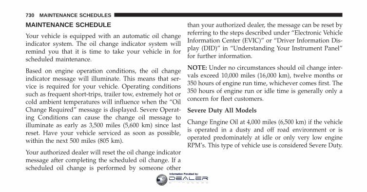
MAINTENANCE SCHEDULE
Your vehicle is equipped with an automatic oil changeindicator system. The oil change indicator system willremind you that it is time to take your vehicle in forscheduled maintenance.
Based on engine operation conditions, the oil changeindicator message will illuminate. This means that ser-vice is required for your vehicle. Operating conditionssuch as frequent short-trips, trailer tow, extremely hot orcold ambient temperatures will influence when the “OilChange Required” message is displayed. Severe Operat-ing Conditions can cause the change oil message toilluminate as early as 3,500 miles (5,600 km) since lastreset. Have your vehicle serviced as soon as possible,within the next 500 miles (805 km).
Your authorized dealer will reset the oil change indicatormessage after completing the scheduled oil change. If ascheduled oil change is performed by someone other
than your authorized dealer, the message can be reset byreferring to the steps described under “Electronic VehicleInformation Center (EVIC)” or “Driver Information Dis-play (DID)” in “Understanding Your Instrument Panel”for further information.
NOTE: Under no circumstances should oil change inter-vals exceed 10,000 miles (16,000 km), twelve months or350 hours of engine run time, whichever comes first. The350 hours of engine run or idle time is generally only aconcern for fleet customers.
Severe Duty All Models
Change Engine Oil at 4,000 miles (6,500 km) if the vehicleis operated in a dusty and off road environment or isoperated predominately at idle or only very low engineRPM’s. This type of vehicle use is considered Severe Duty.
730 MAINTENANCE SCHEDULES
Information Provided by:
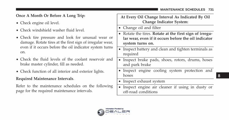
Once A Month Or Before A Long Trip:
• Check engine oil level.
• Check windshield washer fluid level.
• Check tire pressure and look for unusual wear ordamage. Rotate tires at the first sign of irregular wear,even if it occurs before the oil indicator system turnson.
• Check the fluid levels of the coolant reservoir andbrake master cylinder, fill as needed.
• Check function of all interior and exterior lights.
Required Maintenance Intervals.
Refer to the maintenance schedules on the followingpage for the required maintenance intervals.
At Every Oil Change Interval As Indicated By OilChange Indicator System:
• Change oil and filter• Rotate the tires. Rotate at the first sign of irregu-
lar wear, even if it occurs before the oil indicatorsystem turns on.
• Inspect battery and clean and tighten terminals asrequired
• Inspect brake pads, shoes, rotors, drums, hosesand park brake
• Inspect engine cooling system protection andhoses
• Inspect exhaust system• Inspect engine air cleaner if using in dusty or
off-road conditions
8
MAINTENANCE SCHEDULES 731
Information Provided by:
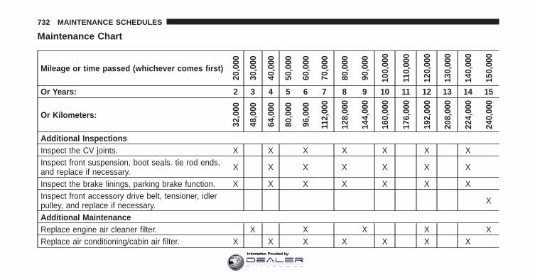
Maintenance Chart
Mileage or time passed (whichever comes first)
20,0
00
30,0
00
40,0
00
50,0
00
60,0
00
70,0
00
80,0
00
90,0
00
100,
000
110,
000
120,
000
130,
000
140,
000
150,
000
Or Years: 2 3 4 5 6 7 8 9 10 11 12 13 14 15
Or Kilometers:
32,0
00
48,0
00
64,0
00
80,0
00
96,0
00
112,
000
128,
000
144,
000
160,
000
176,
000
192,
000
208,
000
224,
000
240,
000
Additional InspectionsInspect the CV joints. X X X X X X XInspect front suspension, boot seals. tie rod ends,and replace if necessary. X X X X X X X
Inspect the brake linings, parking brake function. X X X X X X XInspect front accessory drive belt, tensioner, idlerpulley, and replace if necessary. X
Additional MaintenanceReplace engine air cleaner filter. X X X X XReplace air conditioning/cabin air filter. X X X X X X X
732 MAINTENANCE SCHEDULES
Information Provided by:
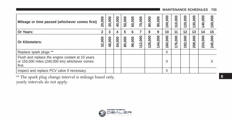
Mileage or time passed (whichever comes first)
20,0
00
30,0
00
40,0
00
50,0
00
60,0
00
70,0
00
80,0
00
90,0
00
100,
000
110,
000
120,
000
130,
000
140,
000
150,
000
Or Years: 2 3 4 5 6 7 8 9 10 11 12 13 14 15
Or Kilometers:
32,0
00
48,0
00
64,0
00
80,0
00
96,0
00
112,
000
128,
000
144,
000
160,
000
176,
000
192,
000
208,
000
224,
000
240,
000
Replace spark plugs ** XFlush and replace the engine coolant at 10 yearsor 150,000 miles (240,000 km) whichever comesfirst.
X X
Inspect and replace PCV valve if necessary. X
** The spark plug change interval is mileage based only,yearly intervals do not apply.
8
MAINTENANCE SCHEDULES 733
Information Provided by:
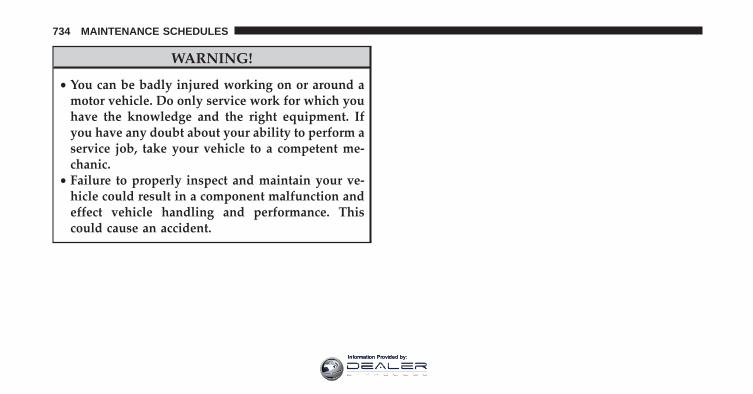
WARNING!
• You can be badly injured working on or around amotor vehicle. Do only service work for which youhave the knowledge and the right equipment. Ifyou have any doubt about your ability to perform aservice job, take your vehicle to a competent me-chanic.
• Failure to properly inspect and maintain your ve-hicle could result in a component malfunction andeffect vehicle handling and performance. Thiscould cause an accident.
734 MAINTENANCE SCHEDULES
Information Provided by:
IF YOU NEED CONSUMER ASSISTANCE
CONTENTS� SUGGESTIONS FOR OBTAINING SERVICE FOR
YOUR VEHICLE . . . . . . . . . . . . . . . . . . . . . . .737
▫ Prepare For The Appointment. . . . . . . . . . . . .737
▫ Prepare A List . . . . . . . . . . . . . . . . . . . . . . . .737
▫ Be Reasonable With Requests . . . . . . . . . . . . .737
� IF YOU NEED ASSISTANCE . . . . . . . . . . . . . .737
▫ FCA US LLC Customer Center . . . . . . . . . . . .738
▫ FCA Canada Inc. Customer Center . . . . . . . . .738
▫ In Mexico Contact . . . . . . . . . . . . . . . . . . . . .739
▫ Puerto Rico And U.S. Virgin Islands . . . . . . . .739
▫ Customer Assistance For The Hearing OrSpeech Impaired (TDD/TTY) . . . . . . . . . . . . .739
▫ Service Contract . . . . . . . . . . . . . . . . . . . . . .739
� WARRANTY INFORMATION . . . . . . . . . . . . .741
� MOPAR PARTS . . . . . . . . . . . . . . . . . . . . . . . .741
� REPORTING SAFETY DEFECTS . . . . . . . . . . . .741
▫ In The 50 United States AndWashington, D.C.. . . . . . . . . . . . . . . . . . . . . .741
▫ In Canada . . . . . . . . . . . . . . . . . . . . . . . . . . .741
� PUBLICATION ORDER FORMS . . . . . . . . . . . .742
9
Information Provided by:
� DEPARTMENT OF TRANSPORTATION UNIFORMTIRE QUALITY GRADES . . . . . . . . . . . . . . . . .743
▫ Treadwear. . . . . . . . . . . . . . . . . . . . . . . . . . .743
▫ Traction Grades . . . . . . . . . . . . . . . . . . . . . . .743
▫ Temperature Grades. . . . . . . . . . . . . . . . . . . .744
736 IF YOU NEED CONSUMER ASSISTANCE
Information Provided by:
SUGGESTIONS FOR OBTAINING SERVICE FORYOUR VEHICLE
Prepare For The Appointment
If you are having warranty work done, be sure to havethe right papers with you. Take your warranty folder. Allwork to be performed may not be covered by thewarranty. Discuss additional charges with the servicemanager. Keep a maintenance log of your vehicle’sservice history. This can often provide a clue to thecurrent problem.
Prepare A List
Make a written list of your vehicle’s problems or thespecific work you want done. If you’ve had an accidentor work done that is not on your maintenance log, let theservice advisor know.
Be Reasonable With Requests
If you list a number of items and you must have yourvehicle by the end of the day, discuss the situation withthe service advisor and list the items in order of priority.At many authorized dealers, you may obtain a rentalvehicle at a minimal daily charge. If you need a rental, itis advisable to make these arrangements when you callfor an appointment.
IF YOU NEED ASSISTANCE
The manufacturer and its authorized dealer are vitallyinterested in your satisfaction. We want you to be happywith our products and services.
Warranty service must be done by an authorized dealer.We strongly recommend that you take the vehicle to anauthorized dealer. They know your vehicle the best, andare most concerned that you get prompt and high qualityservice. The manufacturer’s authorized dealer have the
9
IF YOU NEED CONSUMER ASSISTANCE 737
Information Provided by:
facilities, factory-trained technicians, special tools, andthe latest information to ensure the vehicle is fixedcorrectly and in a timely manner.
This is why you should always talk to an authorizeddealer service manager first. Most matters can be re-solved with this process.
• If for some reason you are still not satisfied, talk to thegeneral manager or owner of the authorized dealer.They want to know if you need assistance.
• If an authorized dealer is unable to resolve the con-cern, you may contact the manufacturer’s customercenter.
Any communication to the manufacturer’s customer cen-ter should include the following information:
• Owner’s name and address
• Owner’s telephone number (home and office)
• Authorized dealer name
• Vehicle Identification Number (VIN)
• Vehicle delivery date and mileage
FCA US LLC Customer Center
P.O. Box 21–8004
Auburn Hills, MI 48321–8004
Phone: (877) 426-5337
FCA Canada Inc. Customer Center
P.O. Box 1621
Windsor, Ontario N9A 4H6
Phone: (800) 465-2001 English / (800) 387-9983 French
738 IF YOU NEED CONSUMER ASSISTANCE
Information Provided by:
In Mexico Contact
Av. Prolongacion Paseo de la Reforma, 1240
Sante Fe C.P. 05109
Mexico, D. F.
In Mexico City: 5081-7568
Outside Mexico City: 1-800-505-1300
Puerto Rico And U.S. Virgin Islands
Customer Service Chrysler International Services LLC
P.O. Box 191857
San Juan 00919-1857
Tel.: (787) 782-5757
Fax: (787) 782-3345
Customer Assistance For The Hearing Or SpeechImpaired (TDD/TTY)
To assist customers who have hearing difficulties, themanufacturer has installed special TDD (Telecommuni-cation Devices for the Deaf) equipment at its customercenter. Any hearing or speech impaired customer, whohas access to a TDD or a conventional teletypewriter(TTY) in the United States, can communicate with themanufacturer by dialing 1-800-380-CHRY.
Canadian residents with hearing difficulties that requireassistance can use the special needs relay service offeredby Bell Canada. For TTY teletypewriter users, dial 711and for Voice callers, dial 1-800-855-0511 to connect witha Bell Relay Service operator.
Service Contract
You may have purchased a service contract for a vehicleto help protect you from the high cost of unexpectedrepairs after the manufacturer’s New Vehicle Limited
9
IF YOU NEED CONSUMER ASSISTANCE 739
Information Provided by:
Warranty expires. The manufacturer stands behind onlythe manufacturer’s service contracts. If you purchased amanufacturer’s service contract, you will receive PlanProvisions and an Owner Identification Card in the mailwithin three weeks of the vehicle delivery date. If youhave any questions about the service contract, call themanufacturer’s Service Contract National CustomerHotline at 1-800-521-9922 (Canadian residents, call (800)465-2001 English / (800) 387-9983 French).
The manufacturer will not stand behind any servicecontract that is not the manufacturer’s service contract. Itis not responsible for any service contract other than themanufacturer’s service contract. If you purchased a ser-vice contract that is not a manufacturer’s service contract,and you require service after the manufacturer’s NewVehicle Limited Warranty expires, please refer to thecontract documents, and contact the person listed inthose documents.
We appreciate that you have made a major investmentwhen you purchased the vehicle. An authorized dealerhas also made a major investment in facilities, tools, andtraining to assure that you are absolutely delighted withthe ownership experience. You will be pleased with theirsincere efforts to resolve any warranty issues or relatedconcerns.
WARNING!
Engine exhaust (internal combustion engines only),some of its constituents, and certain vehicle compo-nents contain, or emit, chemicals known to the Stateof California to cause cancer and birth defects, orother reproductive harm. In addition, certain fluidscontained in vehicles and certain products of compo-nent wear contain, or emit, chemicals known to theState of California to cause cancer and birth defects,or other reproductive harm.
740 IF YOU NEED CONSUMER ASSISTANCE
Information Provided by:

WARRANTY INFORMATION
See the Warranty Information Booklet, located on theDVD, for the terms and provisions of FCA US LLCwarranties applicable to this vehicle and market.
MOPAR PARTS
MOPAR fluids, lubricants, parts, and accessories areavailable from an authorized dealer. They are recom-mended for your vehicle in order to help keep the vehicleoperating at its best.
REPORTING SAFETY DEFECTS
In The 50 United States And Washington, D.C.
If you believe that your vehicle has a defect that couldcause a crash or cause injury or death, you shouldimmediately inform the National Highway Traffic SafetyAdministration (NHTSA) in addition to notifying themanufacturer.
If NHTSA receives similar complaints, it may open aninvestigation, and if it finds that a safety defect exists ina group of vehicles, it may order a recall and remedycampaign. However, NHTSA cannot become involved inindividual problems between you, your authorizeddealer, and the manufacturer.
To contact NHTSA, you may either call the Auto SafetyHotline toll free at 1-888-327-4236 (TTY: 1-800-424-9153),or go to http://www.safercar.gov; or write to: Adminis-trator, NHTSA, 1200 New Jersey Avenue, SE., WestBuilding, Washington, D.C. 20590.
You can also obtain other information about motorvehicle safety from http://www.safercar.gov.
In Canada
If you believe that your vehicle has a safety defect, youshould contact the Customer Service Department imme-diately. Canadian customers who wish to report a safety
9
IF YOU NEED CONSUMER ASSISTANCE 741
Information Provided by:
defect to the Canadian government should contact Trans-port Canada, Motor Vehicle Defect Investigations andRecalls at 1-800-333-0510 or go to http://www.tc.gc.ca/roadsafety/
PUBLICATION ORDER FORMS
To order the following manuals, you may use either thewebsite or the phone numbers listed below. Visa, Mas-tercard, American Express, and Discover orders are ac-cepted. If you prefer mailing your payment, please callfor an order form.
NOTE: A street address is required when orderingmanuals (no P.O. Boxes).
Service Manuals
These comprehensive Service Manuals provide the infor-mation that students and professional technicians need indiagnosing/troubleshooting, problem solving, maintain-ing, servicing, and repairing FCA US LLC vehicles. A
complete working knowledge of the vehicle, system,and/or components is written in straightforward lan-guage with illustrations, diagrams, and charts.
Diagnostic Procedure Manuals
Diagnostic Procedure Manuals are filled with diagrams,charts and detailed illustrations. These practical manualsmake it easy for students and technicians to find and fixproblems on computer-controlled vehicle systems andfeatures. They show exactly how to find and correctproblems the first time, using step-by-step troubleshoot-ing and drivability procedures, proven diagnostic testsand a complete list of all tools and equipment.
Owner’s Manuals
These Owner’s Manuals have been prepared with theassistance of service and engineering specialists to acquaintyou with specific FCA US LLC vehicles. Included are
742 IF YOU NEED CONSUMER ASSISTANCE
Information Provided by:
starting, operating, emergency and maintenance proce-dures as well as specifications, capabilities and safety tips.
Call toll free at:
• 1-800-890-4038 (U.S.)
• 1-800-387-1143 (Canada)
Or
Visit us on the Worldwide Web at:
• www.techauthority.com
DEPARTMENT OF TRANSPORTATION UNIFORMTIRE QUALITY GRADES
The following tire grading categories were established bythe National Highway Traffic Safety Administration. Thespecific grade rating assigned by the tire’s manufacturerin each category is shown on the sidewall of the tires onyour vehicle.
All passenger vehicle tires must conform to Federalsafety requirements in addition to these grades.
Treadwear
The Treadwear grade is a comparative rating, based onthe wear rate of the tire when tested under controlledconditions on a specified government test course. Forexample, a tire graded 150 would wear one and one-halftimes as well on the government course as a tire graded100. The relative performance of tires depends upon theactual conditions of their use, however, and may departsignificantly from the norm due to variations in drivinghabits, service practices, and differences in road charac-teristics and climate.
Traction Grades
The Traction grades, from highest to lowest, are AA, A, B,and C. These grades represent the tire’s ability to stop onwet pavement, as measured under controlled conditions on
9
IF YOU NEED CONSUMER ASSISTANCE 743
Information Provided by:
specified government test surfaces of asphalt and concrete.A tire marked C may have poor traction performance.
WARNING!
The traction grade assigned to this tire is based onstraight-ahead braking traction tests, and does notinclude acceleration, cornering, hydroplaning, orpeak traction characteristics.
Temperature Grades
The temperature grades are A (the highest), B, and C,representing the tire’s resistance to the generation of heatand its ability to dissipate heat, when tested undercontrolled conditions on a specified indoor laboratorytest wheel. Sustained high temperature can cause the
material of the tire to degenerate and reduce tire life, andexcessive temperature can lead to sudden tire failure. Thegrade C corresponds to a level of performance, which allpassenger vehicle tires must meet under the FederalMotor Vehicle Safety Standard No. 109. Grades B and Arepresent higher levels of performance on the laboratorytest wheel, than the minimum required by law.
WARNING!
The temperature grade for this tire is established fora tire that is properly inflated and not overloaded.Excessive speed, under-inflation, or excessive load-ing, either separately or in combination, can causeheat buildup and possible tire failure.
744 IF YOU NEED CONSUMER ASSISTANCE
Information Provided by:

INDEX
10
Information Provided by:
About Your Brakes . . . . . . . . . . . . . . . . . . . . . . . .519Adaptive Cruise Control (ACC) (Cruise Control) . . .187Adding Engine Coolant (Antifreeze) . . . . . . . . . . . .692Additives, Fuel . . . . . . . . . . . . . . . . . . . . . . . . . . .579Air Bag. . . . . . . . . . . . . . . . . . . . . . . . . . . . . . .66, 67
Advance Front Air Bag . . . . . . . . . . . . . . . . . . . .68Air Bag Operation . . . . . . . . . . . . . . . . . . . . . . .69Air Bag Warning Light . . . . . . . . . . . . . . . . . .70, 87Driver Knee Air Bag . . . . . . . . . . . . . . . . . . . . . .79Enhanced Accident Response . . . . . . . . . . . . . . . .86Event Data Recorder (EDR) . . . . . . . . . . . . . . . . .90Front Air Bag . . . . . . . . . . . . . . . . . . . . . . . .66, 70Front Passenger Knee Air Bag . . . . . . . . . . . . . . .79If A Deployment Occurs . . . . . . . . . . . . . . . . . . .85Knee Impact Bolsters . . . . . . . . . . . . . . . . . . . . .79Maintaining Your Air Bag System . . . . . . . . . . . .89Redundant Air Bag Warning Light . . . . . . . . . . . .89Side Air Bags . . . . . . . . . . . . . . . . . . . . . . . . . . .79Transporting Pets . . . . . . . . . . . . . . . . . . . . . . .113
Air Bag Deployment . . . . . . . . . . . . . . . . . . . . . . . .66Air Bag Light . . . . . . . . . . . . . . . . . . . . . .87, 116, 328Air Bag Maintenance . . . . . . . . . . . . . . . . . . . . . . .89Air Cleaner, Engine (Engine Air Cleaner Filter) . . . .669Air Conditioner Maintenance . . . . . . . . . . . . . . . . .675Air Conditioning . . . . . . . . . . . . . . . . . . . . . .421, 426Air Conditioning Controls . . . . . . . . . . . . . . . .421, 426Air Conditioning Filter . . . . . . . . . . . . . . . . . .444, 677Air Conditioning, Operating Tips. . . . . . . . . . .442, 445Air Conditioning Refrigerant . . . . . . . . . . . . . .675, 676Air Conditioning System . . . . . . .421, 426, 432, 441, 675Air Filter . . . . . . . . . . . . . . . . . . . . . . . . . . . . . . .669Air Pressure, Tires. . . . . . . . . . . . . . . . . . . . . . . . .553Alarm
Arm The System . . . . . . . . . . . . . . . . . . . . . . . .20Alarm, Panic . . . . . . . . . . . . . . . . . . . . . . . . . . . . .25Alarm (Security Alarm) . . . . . . . . . . . . . . . . . .19, 331Alarm System (Security Alarm) . . . . . . . . . . . . . . . .19All Wheel Drive (AWD). . . . . . . . . . . . . . . . . . . . .494
746 INDEX
Information Provided by:
Alterations/Modifications, Vehicle . . . . . . . . . . . . . . .8Antifreeze (Engine Coolant). . . . . . . . . . . . . . .691, 725
Disposal . . . . . . . . . . . . . . . . . . . . . . . . . . . . . .694Anti-Lock Brake System (ABS) . . . . . . . . . . . . . . . .520Anti-Lock Warning Light . . . . . . . . . . . . . . . . . . . .345Appearance Care . . . . . . . . . . . . . . . . . . . . . . . . .700Arming System (Security Alarm) . . . . . . . . . . . . . . .19Assist, Hill Start . . . . . . . . . . . . . . . . . . . . . . . . . .523Auto Down Power Windows . . . . . . . . . . . . . . . . . .46Automatic Door Locks . . . . . . . . . . . . . . . . . . . .36, 37Automatic Headlights . . . . . . . . . . . . . . . . . . . . . .166Automatic High Beams . . . . . . . . . . . . . . . . . . . . .168Automatic Temperature Control (ATC). . . .421, 432, 441Automatic Transaxle . . . . . . . . . . . . . . . . . . . . . . .483Automatic Transmission . . . . . . . . . . . . . . . . .485, 699
Adding Fluid . . . . . . . . . . . . . . . . . . . . . . .699, 728Fluid And Filter Changes . . . . . . . . . . . . . . . . . .699Fluid Change . . . . . . . . . . . . . . . . . . . . . . . . . .699Fluid Level Check . . . . . . . . . . . . . . . . . . .698, 699
Fluid Type . . . . . . . . . . . . . . . . . . . . . . . . .698, 728Special Additives . . . . . . . . . . . . . . . . . . . . . . .698Torque Converter . . . . . . . . . . . . . . . . . . . . . . .494
Auto Unlock, Doors . . . . . . . . . . . . . . . . . . . . . . . .37Auto Up Power Windows . . . . . . . . . . . . . . . . . . . .46Auxiliary Electrical Outlet (Power Outlet) . . . . . . . .296Auxiliary Power Outlet . . . . . . . . . . . . . . . . . . . . .296Axle Fluid . . . . . . . . . . . . . . . . . . . . . . . . . . . . . .728Axle Lubrication . . . . . . . . . . . . . . . . . . . . . . . . . .728
Battery . . . . . . . . . . . . . . . . . . . . . . . . . . . . .334, 674Charging System Light . . . . . . . . . . . . . . . . . . .334Keyless Transmitter Replacement (RKE) . . . . . . . .26
Belts, Seat. . . . . . . . . . . . . . . . . . . . . . . . . . . . . . .116Blind Spot Monitoring . . . . . . . . . . . . . . . . . . . . . .137Body Mechanism Lubrication . . . . . . . . . . . . . . . . .679B-Pillar Location . . . . . . . . . . . . . . . . . . . . . . . . . .547Brake Assist System . . . . . . . . . . . . . . . . . . . . . . .522Brake Control System, Electronic . . . . . . . . . . . . . .520
10
INDEX 747
Information Provided by:
Brake Fluid . . . . . . . . . . . . . . . . . . . . . . . . . . . . .728Brakes . . . . . . . . . . . . . . . . . . . . . . . . . . . . . . . . .519Brake System . . . . . . . . . . . . . . . . . . . . . . . . .519, 696
Fluid Check . . . . . . . . . . . . . . . . . . . . . . . .696, 728Master Cylinder . . . . . . . . . . . . . . . . . . . . . . . .696Warning Light . . . . . . . . . . . . . . . . . . . . . . . . .329
Brake/Transmission Interlock. . . . . . . . . . . . . . . . .485Brightness, Interior Lights . . . . . . . . . . . . . . . . . . .172Bulb Replacement. . . . . . . . . . . . . . . . . . . . . .718, 720Bulbs, Light . . . . . . . . . . . . . . . . . . . . . . . . . .118, 718
Camera, Rear . . . . . . . . . . . . . . . . . . . . . . . . . . . .280Capacities, Fluid . . . . . . . . . . . . . . . . . . . . . . . . . .725Caps, Filler
Fuel . . . . . . . . . . . . . . . . . . . . . . . . . . . . . . . . .584Oil (Engine) . . . . . . . . . . . . . . . . . . . .659, 660, 667Radiator (Coolant Pressure) . . . . . . . . . . . . . . . .694
Carbon Monoxide Warning . . . . . . . . . . . . . . .115, 581Cargo Area Features . . . . . . . . . . . . . . . . . . . . . . .309
Cargo Compartment . . . . . . . . . . . . . . . . . . . . . . .309Cargo Load Floor . . . . . . . . . . . . . . . . . . . . . . . . .309Cargo Tie-Downs . . . . . . . . . . . . . . . . . . . . . . . . .310Car Washes . . . . . . . . . . . . . . . . . . . . . . . . . . . . .700Certification Label. . . . . . . . . . . . . . . . . . . . . . . . .588Changing A Flat Tire . . . . . . . . . . . . . . . . . . . . . . .631Chart, Tire Sizing . . . . . . . . . . . . . . . . . . . . . . . . .542Check Engine Light (Malfunction Indicator Light) . .662Checking Your Vehicle For Safety . . . . . . . . . . . . . .114Checks, Safety. . . . . . . . . . . . . . . . . . . . . . . . . . . .114Child Restraint . . . . . . . . . . . . . . . . . . . . . . . . . . . .91Child Restraints
Booster Seats . . . . . . . . . . . . . . . . . . . . . . . . . . .96Child Restraints . . . . . . . . . . . . . . . . . . . . . . . . .91Child Seat Installation . . . . . . . . . . . . . . . . . . . .110How To Stow An Unused ALR Seat Belt . . . . . . .107Infants And Child Restraints . . . . . . . . . . . . . . . .94Install A LATCH-Compatible Child Restraint . . . .105
748 INDEX
Information Provided by:
Installing Child Restraints Using The Vehicle SeatBelt . . . . . . . . . . . . . . . . . . . . . . . . . . . . . . . . .108LATCH Positions . . . . . . . . . . . . . . . . . . . . . . . .99Locating The LATCH Anchorages . . . . . . . . . . . .102Lower Anchors And Tethers For Children . . . . . . .98Older Children And Child Restraints . . . . . . . . . .94Seating Positions . . . . . . . . . . . . . . . . . . . . . . . .97
Child Safety Locks . . . . . . . . . . . . . . . . . . . . . . . . .37Clean Air Gasoline . . . . . . . . . . . . . . . . . . . . . . . .577Cleaning
Wheels . . . . . . . . . . . . . . . . . . . . . . . . . . . . . . .702Climate Control . . . . . . . . . . . . . . . . . . . . . . . . . .421
Automatic . . . . . . . . . . . . . . . . . . . . . . . . . . . .421Coin Holder . . . . . . . . . . . . . . . . . . . . . . . . . . . . .307Cold Weather Operation . . . . . . . . . . . . . . . . . . . .475Compact Disc (CD) Maintenance . . . . . . . . . . . . . .418Compact Spare Tire . . . . . . . . . . . . . . . . . . . . . . . .559Console . . . . . . . . . . . . . . . . . . . . . . . . . . . . . . . .307Console, Floor . . . . . . . . . . . . . . . . . . . . . . . . . . .307
Contract, Service . . . . . . . . . . . . . . . . . . . . . . . . . .739Coolant Pressure Cap (Radiator Cap) . . . . . . . . . . .694Cooling System. . . . . . . . . . . . . . . . . . . . . . . . . . .690
Adding Coolant (Antifreeze) . . . . . . . . . . . . . . .692Coolant Capacity . . . . . . . . . . . . . . . . . . . . . . .725Coolant Level . . . . . . . . . . . . . . . . . . . . . . . . . .695Disposal Of Used Coolant . . . . . . . . . . . . . . . . .694Drain, Flush, And Refill . . . . . . . . . . . . . . . . . . .691Inspection . . . . . . . . . . . . . . . . . . . . . . . . .690, 695Points To Remember . . . . . . . . . . . . . . . . . . . . .695Pressure Cap . . . . . . . . . . . . . . . . . . . . . . . . . .694Radiator Cap . . . . . . . . . . . . . . . . . . . . . . . . . .694Selection Of Coolant (Antifreeze) . . . . . .691, 725, 726
Corrosion Protection . . . . . . . . . . . . . . . . . . . . . . .700Cruise Control (Speed Control). . . . . . . . . . . . . . . .187Cruise Light. . . . . . . . . . . . . . . . . . . . . . . . . .357, 358Cupholders . . . . . . . . . . . . . . . . . . . . . . . . . . . . .305Customer Assistance . . . . . . . . . . . . . . . . . . . . . . .737
10
INDEX 749
Information Provided by:
Data Recorder, Event . . . . . . . . . . . . . . . . . . . . . . .90Daytime Brightness, Interior Lights. . . . . . . . . . . . .174Daytime Running Lights . . . . . . . . . . . . . . . . . . . .168Dealer Service. . . . . . . . . . . . . . . . . . . . . . . . . . . .664Defroster, Rear Window. . . . . . . . . . . . . . . . . . . . .313Defroster, Windshield . . . . . . . . . . . . . . . .116, 423, 424Diagnostic System, Onboard . . . . . . . . . . . . . . . . .661Dimmer Switch, Headlight. . . . . . . . . . . . . . . . . . .171Dipsticks
Oil (Engine) . . . . . . . . . . . . . . . . . . . . . . . . . . .665Disabled Vehicle Towing . . . . . . . . . . . . . . . . . . . .652Disposal
Antifreeze (Engine Coolant) . . . . . . . . . . . . . . . .694Door Ajar . . . . . . . . . . . . . . . . . . . . . . . . . . .336, 337Door Ajar Light . . . . . . . . . . . . . . . . . . . . . . .336, 337Door Locks
Door Locks . . . . . . . . . . . . . . . . . . . . . . . . . . . .34Key Fob . . . . . . . . . . . . . . . . . . . . . . . . . . . . . . .34Remote . . . . . . . . . . . . . . . . . . . . . . . . . . . . . . .34
Remote Keyless Entry (RKE) . . . . . . . . . . . . . . . .34Door Locks, Automatic . . . . . . . . . . . . . . . . . . . . . .36Door Opener, Garage. . . . . . . . . . . . . . . . . . . . . . .282Driver Information Display
DID . . . . . . . . . . . . . . . . . . . . . . . . . . . . . . . . .373Instrument Cluster Display . . . . . . . . . . . . . . . .373
Driver Information Display (DID)Instrument Cluster . . . . . . . . . . . . . . . . . . . . . .372Oil Change . . . . . . . . . . . . . . . . . . . . . . . . . . . .372
Driver’s Seat Back Tilt . . . . . . . . . . . . . . . . . . . . . .149Driving . . . . . . . . . . . . . . . . . . . . . . . . . . . . . . . .506
E-85 Fuel . . . . . . . . . . . . . . . . . . . . . . . . . . . . . . .581Electrical Outlet, Auxiliary (Power Outlet) . . . . . . . .296Electric Parking Brake . . . . . . . . . . . . . . . . . . . . . .512Electric Remote Mirrors . . . . . . . . . . . . . . . . . . . . .134Electronic Brake Control System . . . . . . . . . . . . . . .520
Anti-Lock Brake System . . . . . . . . . . . . . . . . . .520Electronic Roll Mitigation . . . . . . . . . . . . . . . . .532
750 INDEX
Information Provided by:
Traction Control System . . . . . . . . . . . . . . . . . . .526Electronic Range Select (ERS) . . . . . . . . . . . . . . . . .493Electronic Speed Control (Cruise Control) . . . . .183, 187Electronic Stability Control (ESC) . . . . . . . . . . . . . .527Electronic Throttle Control Warning Light . . . . . . . .335Electronic Vehicle Information Center (EVIC) . . . . . .280
Change Engine Oil . . . . . . . . . . . . . . . . . . . . . .363Electronic Vehicle Information Center (EVIC) . . . .361Selectable Menu Items . . . . . . . . . . . . . . . . . . . .364
Emergency, In Case OfHazard Warning Flasher . . . . . . . . . . . . . . . . . .617Jacking . . . . . . . . . . . . . . . . . . . . . . . . . . . . . . .631Jump Starting . . . . . . . . . . . . . . . . . . . . . . . . . .644Overheating . . . . . . . . . . . . . . . . . . . . . . . . . . .617
Emission Control System Maintenance . . . . . . . . . .662Engine. . . . . . . . . . . . . . . . . . . . . . . . . . . . . .659, 660
Air Cleaner . . . . . . . . . . . . . . . . . . . . . . . . . . .669Block Heater . . . . . . . . . . . . . . . . . . . . . . . . . .482Break-In Recommendations . . . . . . . . . . . . . . . .113
Checking Oil Level . . . . . . . . . . . . . . . . . . . . . .665Coolant (Antifreeze) . . . . . . . . . . . . . . . . . . . . .726Cooling . . . . . . . . . . . . . . . . . . . . . . . . . . . . . .690Exhaust Gas Caution . . . . . . . . . . . . . . . . .115, 581Fails To Start . . . . . . . . . . . . . . . . . . . . . . . . . .476Flooded, Starting . . . . . . . . . . . . . . . . . . . . . . .476Fuel Requirements . . . . . . . . . . . . . . . . . . . . . .577Jump Starting . . . . . . . . . . . . . . . . . . . . . . . . . .644Oil . . . . . . . . . . . . . . . . . . . . . . . . . . .665, 725, 726Oil Filler Cap . . . . . . . . . . . . . . . . . . .659, 660, 667Oil Filter . . . . . . . . . . . . . . . . . . . . . . . . . . . . .668Oil Selection . . . . . . . . . . . . . . . . . . . . . . .666, 725Oil Synthetic . . . . . . . . . . . . . . . . . . . . . . . . . .668Overheating . . . . . . . . . . . . . . . . . . . . . . . . . . .617Starting . . . . . . . . . . . . . . . . . . . . . . . . . . .474, 475
Engine Oil Viscosity . . . . . . . . . . . . . . . . . . . . . . .667Engine Oil Viscosity Chart . . . . . . . . . . . . . . . . . . .667Enhanced Accident Response Feature . . . . . . . . . . . .86Entry System, Illuminated . . . . . . . . . . . . . . . . . . . .22
10
INDEX 751
Information Provided by:
Ethanol . . . . . . . . . . . . . . . . . . . . . . . . . . . . .578, 581Event Data Recorder . . . . . . . . . . . . . . . . . . . . . . . .90Exhaust Gas Caution. . . . . . . . . . . . . . . . . . . .115, 581Exhaust System . . . . . . . . . . . . . . . . . . . . . . .115, 688Exterior Lighting. . . . . . . . . . . . . . . . . . . . . . . . . .165Exterior Lights . . . . . . . . . . . . . . . . . . . . . . . . . . .118
FiltersAir Cleaner . . . . . . . . . . . . . . . . . . . . . . . . . . .669Air Conditioning . . . . . . . . . . . . . . . . . . . .444, 677Engine Oil . . . . . . . . . . . . . . . . . . . . . . . . .668, 726Engine Oil Disposal . . . . . . . . . . . . . . . . . . . . .668
FlashersHazard Warning . . . . . . . . . . . . . . . . . . . . . . . .617Turn Signal . . . . . . . . . . . . . . . . . .118, 170, 355, 721
Flash-To-Pass . . . . . . . . . . . . . . . . . . . . . . . . . . . .171Flexible Fuel Vehicles
Cruising Range . . . . . . . . . . . . . . . . . . . . . . . . .584Engine Oil . . . . . . . . . . . . . . . . . . . . . . . . . . . .583
Fuel Requirements . . . . . . . . . . . . . . . . . . .581, 582Maintenance . . . . . . . . . . . . . . . . . . . . . . . . . . .584Replacement Parts . . . . . . . . . . . . . . . . . . . . . . .584Starting . . . . . . . . . . . . . . . . . . . . . . . . . . . . . .583
Flooded Engine Starting . . . . . . . . . . . . . . . . . . . .476Floor Console . . . . . . . . . . . . . . . . . . . . . . . . . . . .307Fluid, Brake . . . . . . . . . . . . . . . . . . . . . . . . . . . . .728Fluid Capacities . . . . . . . . . . . . . . . . . . . . . . . . . .725Fluid Leaks . . . . . . . . . . . . . . . . . . . . . . . . . . . . .118Fluid Level Checks
Brake . . . . . . . . . . . . . . . . . . . . . . . . . . . . . . . .696Engine Oil . . . . . . . . . . . . . . . . . . . . . . . . . . . .665
Fluids, Lubricants And Genuine Parts . . . . . . . . . . .726Fog Lights. . . . . . . . . . . . . . . . . . . . . . . .169, 337, 722Fog Light Service . . . . . . . . . . . . . . . . . . . . . . . . .722Folding Rear Seat . . . . . . . . . . . . . . . . . . . . . . . . .157Forward Collision Warning . . . . . . . . . . . . . . . . . .214Four Wheel Drive . . . . . . . . . . . . . . . . . . . . . . . . .504Freeing A Stuck Vehicle . . . . . . . . . . . . . . . . . . . . .648
752 INDEX
Information Provided by:
Fuel . . . . . . . . . . . . . . . . . . . . . . . . . . . . . . . . . . .577Additives . . . . . . . . . . . . . . . . . . . . . . . . . . . . .579Clean Air . . . . . . . . . . . . . . . . . . . . . . . . . . . . .577Ethanol . . . . . . . . . . . . . . . . . . . . . . . . . . .578, 581Filler Cap (Gas Cap) . . . . . . . . . . . . . . . . . . . . .584Gasoline . . . . . . . . . . . . . . . . . . . . . . . . . . . . . .577Light . . . . . . . . . . . . . . . . . . . . . . . . . . . . . . . .346Materials Added . . . . . . . . . . . . . . . . . . . . . . . .579Methanol . . . . . . . . . . . . . . . . . . . . . . . . . . . . .578Octane Rating . . . . . . . . . . . . . . . . . . . . . .577, 726Requirements . . . . . . . . . . . . . . . . . . . . . . . . . .577Specifications . . . . . . . . . . . . . . . . . . . . . . . . . .726Tank Capacity . . . . . . . . . . . . . . . . . . . . . . . . . .725
Fuel, Flexible . . . . . . . . . . . . . . . . . . . . . . . . . . . .581Fuses . . . . . . . . . . . . . . . . . . . . . . . . . . . . . . . . . .706
Garage Door Opener (HomeLink) . . . . . . . . . .282, 289Gas Cap (Fuel Filler Cap) . . . . . . . . . . . . . . . . . . .584Gasoline, Clean Air . . . . . . . . . . . . . . . . . . . . . . . .577
Gasoline (Fuel) . . . . . . . . . . . . . . . . . . . . . . . . . . .577Gasoline, Reformulated . . . . . . . . . . . . . . . . . . . . .577Gear Ranges . . . . . . . . . . . . . . . . . . . . . . . . . . . . .487Gear Select Lever Override . . . . . . . . . . . . . . . . . .651Glass Cleaning . . . . . . . . . . . . . . . . . . . . . . . . . . .705Gross Axle Weight Rating . . . . . . . . . . . . . . . . . . .592Gross Vehicle Weight Rating. . . . . . . . . . . . . . . . . .591GVWR . . . . . . . . . . . . . . . . . . . . . . . . . . . . . . . . .589
Hazard Warning Flasher . . . . . . . . . . . . . . . . . . . .617Headlights
Automatic . . . . . . . . . . . . . . . . . . . . . . . . . . . .166Bulb Replacement . . . . . . . . . . . . . . . . . . . . . . .720Cleaning . . . . . . . . . . . . . . . . . . . . . . . . . . . . .704Delay . . . . . . . . . . . . . . . . . . . . . . . . . . . . . . . .167High Beam/Low Beam Select Switch . . . . . . . . .171Lights On Reminder . . . . . . . . . . . . . . . . . . . . .169On With Wipers . . . . . . . . . . . . . . . . . . . . . . . .166Passing . . . . . . . . . . . . . . . . . . . . . . . . . . . . . .171
10
INDEX 753
Information Provided by:
Replacing . . . . . . . . . . . . . . . . . . . . . . . . . . . . .720Switch . . . . . . . . . . . . . . . . . . . . . . . . . . . . . . .165Time Delay . . . . . . . . . . . . . . . . . . . . . . . . . . . .167
Head Restraints . . . . . . . . . . . . . . . . . . . . . . . . . .153Head Rests . . . . . . . . . . . . . . . . . . . . . . . . . . . . . .153Heated Mirrors . . . . . . . . . . . . . . . . . . . . . . . . . . .136Heater . . . . . . . . . . . . . . . . . . . . . . . . . . . . . .421, 426Heater, Engine Block . . . . . . . . . . . . . . . . . . . . . . .482High Beam/Low Beam Select (Dimmer) Switch . . . .171Hill Descent Control . . . . . . . . . . . . . . . . . . . . . . .534Hill Descent Control Indicator . . . . . . . . . . . . . . . .534Hill Start Assist. . . . . . . . . . . . . . . . . . . . . . . . . . .523Hitches
Trailer Towing . . . . . . . . . . . . . . . . . . . . . . . . .594Holder, Coin. . . . . . . . . . . . . . . . . . . . . . . . . . . . .307Holder, Cup . . . . . . . . . . . . . . . . . . . . . . . . . . . . .305HomeLink (Garage Door Opener). . . . . . . . . . . . . .282Hood Release . . . . . . . . . . . . . . . . . . . . . . . . . . . .164
IgnitionKey . . . . . . . . . . . . . . . . . . . . . . . . . . . . . . . . . .12
Illuminated Entry . . . . . . . . . . . . . . . . . . . . . . . . . .22Immobilizer (Sentry Key) . . . . . . . . . . . . . . . . . . . .17Inside Rearview Mirror . . . . . . . . . . . . . . . . . . . . .126Instrument Cluster . . . . . . . .321, 324, 332, 333, 349, 355
Instrument Cluster . . . . . . . . . . . . . . . . . . .363, 372Instrument Panel And Controls . . . . . . . . . . . . . . .320Instrument Panel Lens Cleaning . . . . . . . . . . . . . . .705Interior Appearance Care . . . . . . . . . . . . . . . . . . . .703Interior Fuses . . . . . . . . . . . . . . . . . . . . . . . . . . . .716Interior Lights . . . . . . . . . . . . . . . . . . . . . . . . . . .172Intermittent Wipers (Delay Wipers). . . . . . . . . . . . .176Introduction . . . . . . . . . . . . . . . . . . . . . . . . . . . . . .4Inverter, Power . . . . . . . . . . . . . . . . . . . . . . . . . . .300
Jacking Instructions . . . . . . . . . . . . . . . . . . . . . . . .635Jack Location . . . . . . . . . . . . . . . . . . . . . . . . . . . .632Jack Operation . . . . . . . . . . . . . . . . . . . . . . . .631, 635
754 INDEX
Information Provided by:
Jump Starting . . . . . . . . . . . . . . . . . . . . . . . . . . . .644
Key FobArm The Alarm . . . . . . . . . . . . . . . . . . . . . . . . .20Panic Alarm . . . . . . . . . . . . . . . . . . . . . . . . . . . .25Programming Additional Key Fobs . . . . . . . . .19, 26Programming Additional Transmitters . . . . . . .19, 26
Key-In Reminder . . . . . . . . . . . . . . . . . . . . . . . . . .15Keyless Enter-N-Go . . . . . . . . . . . . . . . . . . . . . . . .39
Lock The Vehicle’s Doors . . . . . . . . . . . . . . . . . .390Passive Entry Programming . . . . . . . . . . . . . . . .390Unlock Liftgate . . . . . . . . . . . . . . . . . . . . . . . . .390
Keyless Entry System . . . . . . . . . . . . . . . . . . . . . . .23Key, Replacement . . . . . . . . . . . . . . . . . . . . . . . . . .18Keys . . . . . . . . . . . . . . . . . . . . . . . . . . . . . . . . . . .12Key, Sentry (Immobilizer) . . . . . . . . . . . . . . . . . . . .17
Lane Change And Turn Signals . . . . . . . . . . . . . . .170Lane Change Assist . . . . . . . . . . . . . . . . . . . . . . . .171
LaneSense . . . . . . . . . . . . . . . . . . . . . . . . . . . . . .218Lap/Shoulder Belts. . . . . . . . . . . . . . . . . . . . . . . . .56Latches . . . . . . . . . . . . . . . . . . . . . . . . . . . . . . . .118
Hood . . . . . . . . . . . . . . . . . . . . . . . . . . . . . . . .164Lead Free Gasoline . . . . . . . . . . . . . . . . . . . . . . . .577Leaks, Fluid . . . . . . . . . . . . . . . . . . . . . . . . . . . . .118Life Of Tires . . . . . . . . . . . . . . . . . . . . . . . . . . . . .562Liftgate . . . . . . . . . . . . . . . . . . . . . . . . . . . . . . . . .48Liftgate Window Wiper/Washer . . . . . . . . . . . . . . .312Light Bulbs . . . . . . . . . . . . . . . . . . . . . . . . . .118, 718Lights . . . . . . . . . . . . . . . . . . . . . . . . . . . . . .118, 165
Air Bag . . . . . . . . . . . . . . . . . . . . . . . .87, 116, 328Automatic Headlights . . . . . . . . . . . . . . . . . . . .166Back-Up . . . . . . . . . . . . . . . . . . . . . . . . . . . . . .723Battery Saver . . . . . . . . . . . . . . . . . . . . . . . . . .174Brake Assist Warning . . . . . . . . . . . . . . . . . . . .530Brake Warning . . . . . . . . . . . . . . . . . . . . . . . . .329Bulb Replacement . . . . . . . . . . . . . . . . . . . .718, 720Cruise . . . . . . . . . . . . . . . . . . . . . . . . . . . .357, 358
10
INDEX 755
Information Provided by:
Daytime Running . . . . . . . . . . . . . . . . . . . . . . .168Dimmer Switch, Headlight . . . . . . . . . . . . .170, 171Engine Temperature Warning . . . . . . . . . . . . . . .332Exterior . . . . . . . . . . . . . . . . . . . . . . . . . . . . . .118Fog . . . . . . . . . . . . . . . . . . . . . . . . . .169, 337, 722Hazard Warning Flasher . . . . . . . . . . . . . . . . . .617Headlights . . . . . . . . . . . . . . . . . . . . . . . . .165, 720Headlights On Reminder . . . . . . . . . . . . . . . . . .169Headlights On With Wipers . . . . . . . . . . . . . . . .166Headlight Switch . . . . . . . . . . . . . . . . . . . . . . .165High Beam . . . . . . . . . . . . . . . . . . . . . . . . . . . .171High Beam/Low Beam Select . . . . . . . . . . . . . . .171Hill Descent Control Indicator . . . . . . . . . . . . . .534Illuminated Entry . . . . . . . . . . . . . . . . . . . . . . . .22Instrument Cluster . . . . . . . . . . . . . . . . . . . . . .165Intensity Control . . . . . . . . . . . . . . . . . . . . . . . .172Interior . . . . . . . . . . . . . . . . . . . . . . . . . . . . . .172License . . . . . . . . . . . . . . . . . . . . . . . . . . . . . .724Lights On Reminder . . . . . . . . . . . . . . . . . . . . .169
Low Fuel . . . . . . . . . . . . . . . . . . . . . . . . . . . . .346Malfunction Indicator (Check Engine) . . . . . . . . .338Parade Mode (Daytime Brightness) . . . . . . . . . . .174Park . . . . . . . . . . . . . . . . . . . . . . . . . . . . .354, 356Passing . . . . . . . . . . . . . . . . . . . . . . . . . . . . . .171Rear Servicing . . . . . . . . . . . . . . . . . . . . . . . . .723Rear Tail Lamps . . . . . . . . . . . . . . . . . . . . . . . .723Seat Belt Reminder . . . . . . . . . . . . . . . . . . . . . .327Security Alarm . . . . . . . . . . . . . . . . . . . . . . . . .331Service . . . . . . . . . . . . . . . . . . . . . . . . . . .718, 720Side Marker . . . . . . . . . . . . . . . . . . . . . . . . . . .721Tire Pressure Monitoring (TPMS) . . . . . . . . .342, 569Traction Control . . . . . . . . . . . . . . . . . . . . . . . .530Turn Signal . . . . . . . . . . . . . .118, 170, 355, 721, 723Vanity Mirror . . . . . . . . . . . . . . . . . . . . . . . . . .136Warning (Instrument Cluster Description) . . .332, 355
Load Floor, Cargo . . . . . . . . . . . . . . . . . . . . . . . . .309Loading Vehicle . . . . . . . . . . . . . . . . . . . . . . . . . .588
Tires . . . . . . . . . . . . . . . . . . . . . . . . . . . . . . . .547
756 INDEX
Information Provided by:
Locks . . . . . . . . . . . . . . . . . . . . . . . . . . . . . . . . . .34Automatic Door . . . . . . . . . . . . . . . . . . . . . . . . .36Auto Unlock . . . . . . . . . . . . . . . . . . . . . . . . . . .37Child Protection . . . . . . . . . . . . . . . . . . . . . . . . .37Door . . . . . . . . . . . . . . . . . . . . . . . . . . . . . . . . .34Power Door . . . . . . . . . . . . . . . . . . . . . . . . . . . .35
Low Tire Pressure System . . . . . . . . . . . . . . . . . . .569Lubrication, Body . . . . . . . . . . . . . . . . . . . . . . . . .679Luggage Carrier . . . . . . . . . . . . . . . . . . . . . . . . . .314Lug Nuts . . . . . . . . . . . . . . . . . . . . . . . . . . . . . . .618
Maintenance Free Battery. . . . . . . . . . . . . . . . . . . .674Maintenance Procedures . . . . . . . . . . . . . . . . . . . .664Maintenance Schedule . . . . . . . . . . . . . . . . . . . . . .730Malfunction Indicator Light (Check Engine) . . .338, 662Manual, Service . . . . . . . . . . . . . . . . . . . . . . . . . .742Marker Lights, Side. . . . . . . . . . . . . . . . . . . . . . . .721Master Cylinder (Brakes) . . . . . . . . . . . . . . . . . . . .696Memory Feature (Memory Seat) . . . . . . . . . . . . . . .160
Memory Seat . . . . . . . . . . . . . . . . . . . . . . . . . . . .160Memory Seats And Radio . . . . . . . . . . . . . . . . . . .160Methanol . . . . . . . . . . . . . . . . . . . . . . . . . . . . . . .578Mirrors . . . . . . . . . . . . . . . . . . . . . . . . . . . . . . . .126
Electric Powered . . . . . . . . . . . . . . . . . . . . . . . .134Electric Remote . . . . . . . . . . . . . . . . . . . . . . . . .134Heated . . . . . . . . . . . . . . . . . . . . . . . . . . . . . . .136Outside . . . . . . . . . . . . . . . . . . . . . . . . . . . . . .133Rearview . . . . . . . . . . . . . . . . . . . . . . . . . . . . .126Vanity . . . . . . . . . . . . . . . . . . . . . . . . . . . . . . .136
Modifications/Alterations, Vehicle . . . . . . . . . . . . . . .8Monitor, Tire Pressure System . . . . . . . . . . . . . . . .569MOPAR Parts. . . . . . . . . . . . . . . . . . . . . . . . .663, 741MTBE/ETBE . . . . . . . . . . . . . . . . . . . . . . . . . . . .578Multi-Function Control Lever . . . . . . . . . . . . . . . . .170
New Vehicle Break-In Period . . . . . . . . . . . . . . . . .113
Occupant Restraints . . . . . . . . . . . . . . . . . . . . . . . .52
10
INDEX 757
Information Provided by:
Octane Rating, Gasoline (Fuel) . . . . . . . . . . . . .577, 726Oil, Engine . . . . . . . . . . . . . . . . . . . . . . . . . .665, 726
Capacity . . . . . . . . . . . . . . . . . . . . . . . . . . . . .725Change Interval . . . . . . . . . . . . . . . . . . . . . . . .666Checking . . . . . . . . . . . . . . . . . . . . . . . . . . . . .665Dipstick . . . . . . . . . . . . . . . . . . . . . . . . . . . . . .665Disposal . . . . . . . . . . . . . . . . . . . . . . . . . . . . . .668Filter . . . . . . . . . . . . . . . . . . . . . . . . . . . . .668, 726Filter Disposal . . . . . . . . . . . . . . . . . . . . . . . . .668Identification Logo . . . . . . . . . . . . . . . . . . . . . .666Materials Added To . . . . . . . . . . . . . . . . . . . . . .668Pressure Warning Light . . . . . . . . . . . . . . . . . . .332Recommendation . . . . . . . . . . . . . . . . . . . .666, 725Synthetic . . . . . . . . . . . . . . . . . . . . . . . . . . . . .668Viscosity . . . . . . . . . . . . . . . . . . . . . . . . . .667, 725
Oil Filter, Change . . . . . . . . . . . . . . . . . . . . . . . . .668Oil Filter, Selection . . . . . . . . . . . . . . . . . . . . . . . .668Oil Pressure Light . . . . . . . . . . . . . . . . . . . . . . . . .332Onboard Diagnostic System . . . . . . . . . . . . . . . . . .661
Opener, Garage Door (HomeLink) . . . . . . . . . . . . .282Operating Precautions . . . . . . . . . . . . . . . . . . . . . .661Operator Manual (Owner’s Manual) . . . . . . . . . . . . .5Outside Rearview Mirrors . . . . . . . . . . . . . . . . . . .133Overheating, Engine . . . . . . . . . . . . . . . . . . . . . . .617Owner’s Manual (Operator Manual) . . . . . . . . . .5, 742
Paint Care . . . . . . . . . . . . . . . . . . . . . . . . . . . . . .700Panic Alarm . . . . . . . . . . . . . . . . . . . . . . . . . . . . . .25Parking Brake. . . . . . . . . . . . . . . . . . . . . . . . . . . .512ParkSense System, Rear. . . . . . . . . . . . . . . . . .229, 239Passing Light . . . . . . . . . . . . . . . . . . . . . . . . . . . .171Personalized Menu Bar . . . . . . . . . . . . . . . . . . . . .446Pets . . . . . . . . . . . . . . . . . . . . . . . . . . . . . . . . . . .113Placard, Tire And Loading Information . . . . . . . . . .548Power
Brakes . . . . . . . . . . . . . . . . . . . . . . . . . . . . . . .519Door Locks . . . . . . . . . . . . . . . . . . . . . . . . . . . .35Inverter . . . . . . . . . . . . . . . . . . . . . . . . . . . . . .300
758 INDEX
Information Provided by:
Lift Gate . . . . . . . . . . . . . . . . . . . . . . . . . . . . . .50Mirrors . . . . . . . . . . . . . . . . . . . . . . . . . . . . . .134Outlet (Auxiliary Electrical Outlet) . . . . . . . . . . .296Sunroof . . . . . . . . . . . . . . . . . . . . . . . . . . . . . .291Windows . . . . . . . . . . . . . . . . . . . . . . . . . . . . . .45
Pregnant Women And Seat Belts . . . . . . . . . . . . . . .63Preparation For Jacking . . . . . . . . . . . . . . . . . . . . .634Pretensioners
Seat Belts . . . . . . . . . . . . . . . . . . . . . . . . . . . . . .63Programming Transmitters (Remote Keyless Entry) . .23
Radial Ply Tires . . . . . . . . . . . . . . . . . . . . . . . . . .555Radiator Cap (Coolant Pressure Cap) . . . . . . . . . . .694Radio Frequency
General Information . . . . . . . . . . . .17, 19, 29, 34, 44Radio Operation . . . . . . . . . . . . . . . . . . . . . . . . . .419Radio Remote Controls . . . . . . . . . . . . . . . . . . . . .416Radio (Sound Systems) . . . . . . . . . . . . . . . . . . . . .415Rain Sensitive Wiper System . . . . . . . . . . . . . . . . .179
Rear Camera . . . . . . . . . . . . . . . . . . . . . . . . . . . .280Rear Cross Path . . . . . . . . . . . . . . . . . . . . . . . . . .143Rear ParkSense System . . . . . . . . . . . . . . . . . .229, 239Rear Seat, Folding . . . . . . . . . . . . . . . . . . . . . . . . .157Rear Window Defroster . . . . . . . . . . . . . . . . . . . . .313Rear Window Features . . . . . . . . . . . . . . . . . . . . .312Rear Wiper/Washer. . . . . . . . . . . . . . . . . . . . . . . .312Recorder, Event Data . . . . . . . . . . . . . . . . . . . . . . .90Recreational Towing . . . . . . . . . . . . . . . . . . . . . . .604
Shifting Into Power Transfer Unit Neutral (N) . . .609Shifting Into Transfer Case Neutral (N) . . . . . . . .609Shifting Out Of Power Transfer UnitNeutral (N) . . . . . . . . . . . . . . . . . . . . . . . . . . .612Shifting Out Of Transfer Case Neutral (N) . . . . . .612
Reformulated Gasoline . . . . . . . . . . . . . . . . . . . . .577Refrigerant . . . . . . . . . . . . . . . . . . . . . . . . . . . . . .676Release, Hood. . . . . . . . . . . . . . . . . . . . . . . . . . . .164Reminder, Lights On . . . . . . . . . . . . . . . . . . . . . . .169Reminder, Seat Belt. . . . . . . . . . . . . . . . . . . . . . . . .54
10
INDEX 759
Information Provided by:
Remote ControlStarting System . . . . . . . . . . . . . . . . . . . . . . . . .30
Remote Keyless Entry (RKE) . . . . . . . . . . . . . . . . . .23Arm The Alarm . . . . . . . . . . . . . . . . . . . . . . . . .20Panic Alarm . . . . . . . . . . . . . . . . . . . . . . . . . . . .25Programming Additional Key Fobs . . . . . . . . .19, 26Programming Additional Transmitters . . . . . . .19, 26
Remote Sound System (Radio) Controls . . . . . . . . .416Remote Starting
Exit Remote Start Mode . . . . . . . . . . . . . . . . . . .32Uconnect Customer Programmable Features . .33, 392Uconnect Settings . . . . . . . . . . . . . . . . . . . .33, 392
Remote Starting System. . . . . . . . . . . . . . . . . . . . . .30Replacement Bulbs . . . . . . . . . . . . . . . . . . . . . . . .718Replacement Keys . . . . . . . . . . . . . . . . . . . . . . . . .18Replacement Parts. . . . . . . . . . . . . . . . . . . . . . . . .663Replacement Tires . . . . . . . . . . . . . . . . . . . . . . . . .563Reporting Safety Defects . . . . . . . . . . . . . . . . . . . .741Restraint, Head. . . . . . . . . . . . . . . . . . . . . . . . . . .153
Restraints, Child . . . . . . . . . . . . . . . . . . . . . . . . . . .91Restraints, Occupant . . . . . . . . . . . . . . . . . . . . . . . .52Roll Over Warning . . . . . . . . . . . . . . . . . . . . . . . . . .4Roof Type Carrier . . . . . . . . . . . . . . . . . . . . . . . . .314Rotation, Tires . . . . . . . . . . . . . . . . . . . . . . . . . . .567
Safety Checks Inside Vehicle. . . . . . . . . . . . . . . . . .116Safety Checks Outside Vehicle . . . . . . . . . . . . . . . .118Safety Defects, Reporting . . . . . . . . . . . . . . . . . . . .741Safety, Exhaust Gas . . . . . . . . . . . . . . . . . . . . . . . .115Safety Information, Tire . . . . . . . . . . . . . . . . . . . . .541Safety Tips . . . . . . . . . . . . . . . . . . . . . . . . . . . . . .114Schedule, Maintenance . . . . . . . . . . . . . . . . . . . . .730Seat Belt
Adjustable Upper Shoulder Belt Anchorage . . . . . .61Automatic Locking Retractor (ALR) . . . . . . . . . . .64Energy Management Feature . . . . . . . . . . . . . . . .64Lap/Shoulder Belt Operation . . . . . . . . . . . . . . . .59Lap/Shoulder Belts . . . . . . . . . . . . . . . . . . . . . . .56
760 INDEX
Information Provided by:
Lap/Shoulder Belt Untwisting . . . . . . . . . . . . . . .61Pregnant Women . . . . . . . . . . . . . . . . . . . . . . . .63Seat Belt Extender . . . . . . . . . . . . . . . . . . . . . . .62Seat Belt Pretensioner . . . . . . . . . . . . . . . . . . . . .63Seat Belt Reminder . . . . . . . . . . . . . . . . . . . . . . .54Seat Belt System . . . . . . . . . . . . . . . . . . . . . . . . .52
Seat Belt Maintenance . . . . . . . . . . . . . . . . . . . . . .705Seat Belt Reminder . . . . . . . . . . . . . . . . . . . . . . . . .54Seat Belts. . . . . . . . . . . . . . . . . . . . . . . . . . . . .54, 116
Adjustable Shoulder Belt . . . . . . . . . . . . . . . . . . .61Adjustable Upper Shoulder Anchorage . . . . . . . . .61Child Restraint . . . . . . . . . . . . . . . . . . . . . . . . . .91Extender . . . . . . . . . . . . . . . . . . . . . . . . . . . . . .62Front Seat . . . . . . . . . . . . . . . . . . . . . . . .54, 56, 59Inspection . . . . . . . . . . . . . . . . . . . . . . . . . . . .116Operating Instructions . . . . . . . . . . . . . . . . . . . .59Pregnant Women . . . . . . . . . . . . . . . . . . . . . . . .63Pretensioners . . . . . . . . . . . . . . . . . . . . . . . . . . .63Rear Seat . . . . . . . . . . . . . . . . . . . . . . . . . . . . . .56
Reminder . . . . . . . . . . . . . . . . . . . . . . . . . . . . .327Untwisting Procedure . . . . . . . . . . . . . . . . . . . . .61
Seats . . . . . . . . . . . . . . . . . . . . . . . . . . . . . . .146, 151Adjustment . . . . . . . . . . . . . . . . . . . . . . . .146, 148Easy Entry . . . . . . . . . . . . . . . . . . . . . . . . . . . .163Head Restraints . . . . . . . . . . . . . . . . . . . . . . . .153Heated . . . . . . . . . . . . . . . . . . . . . . . . . . . . . . .151Memory . . . . . . . . . . . . . . . . . . . . . . . . . . . . . .160Rear Folding . . . . . . . . . . . . . . . . . . . . . . . . . .157Seatback Release . . . . . . . . . . . . . . . . . . . .149, 157Tilting . . . . . . . . . . . . . . . . . . . . . . . . . . . . . . .149Vented . . . . . . . . . . . . . . . . . . . . . . . . . . . . . . .152Ventilated . . . . . . . . . . . . . . . . . . . . . . . . . . . . .152
Security Alarm. . . . . . . . . . . . . . . . . . . . . . . . .19, 331Arm The System . . . . . . . . . . . . . . . . . . . . . . . .20
Selec-Terrain . . . . . . . . . . . . . . . . . . . . . . . . . . . . .504Selection Of Coolant (Antifreeze) . . . . . . . . . . . . . .726SENTRY KEY
Key Programming . . . . . . . . . . . . . . . . . . . . . . .19
10
INDEX 761
Information Provided by:
Sentry Key (Immobilizer) . . . . . . . . . . . . . . . . . . . .17Sentry Key Replacement . . . . . . . . . . . . . . . . . . . . .18Service Assistance . . . . . . . . . . . . . . . . . . . . . . . . .737Service Contract . . . . . . . . . . . . . . . . . . . . . . . . . .739Service Manuals . . . . . . . . . . . . . . . . . . . . . . . . . .742Shifting
Automatic Transmission . . . . . . . . . . . . . . . . . .485Power Transfer Unit, Shifting Into Power TransferUnit Neutral (N) . . . . . . . . . . . . . . . . . . . .609, 612Transfer Case, Shifting Into Transfer CaseNeutral (N) . . . . . . . . . . . . . . . . . . . . . . . . . . .609Transfer Case, Shifting Out Of Transfer CaseNeutral (N) . . . . . . . . . . . . . . . . . . . . . . . . . . .612
Shift Lever Override . . . . . . . . . . . . . . . . . . . . . . .651Shoulder Belts . . . . . . . . . . . . . . . . . . . . . . . . . . . .56Side View Mirror Adjustment. . . . . . . . . . . . . . . . .133Signals, Turn. . . . . . . . . . . . . . . . . . .118, 170, 355, 721Snow Chains (Tire Chains) . . . . . . . . . . . . . . . . . . .564Snow Tires . . . . . . . . . . . . . . . . . . . . . . . . . . . . . .557
Spare Tire . . . . . . . . . . . . . . . . . . . . . . . .558, 559, 560Spark Plugs . . . . . . . . . . . . . . . . . . . . . . . . . . . . .726Specifications
Fuel (Gasoline) . . . . . . . . . . . . . . . . . . . . . . . . .726Oil . . . . . . . . . . . . . . . . . . . . . . . . . . . . . . . . . .726
Speed ControlAccel/Decel . . . . . . . . . . . . . . . . . . . . . . . .185, 186Cancel . . . . . . . . . . . . . . . . . . . . . . . . . . . . . . .185
Speed Control (Cruise Control) . . . . . . . . . . . .183, 187Starting . . . . . . . . . . . . . . . . . . . . . . . . . .30, 474, 475
Cold Weather . . . . . . . . . . . . . . . . . . . . . . . . . .475Engine Fails To Start . . . . . . . . . . . . . . . . . . . . .476Remote . . . . . . . . . . . . . . . . . . . . . . . . . . . . . . .30
Starting And Operating. . . . . . . . . . . . . . . . . .474, 475Starting Procedures. . . . . . . . . . . . . . . . . . . . .474, 475Steering
Column Controls . . . . . . . . . . . . . . . . . . . . . . .170Tilt Column . . . . . . . . . . . . . . . . . . . . . . . . . . .180Wheel, Heated . . . . . . . . . . . . . . . . . . . . . . . . .181
762 INDEX
Information Provided by:
Wheel, Tilt . . . . . . . . . . . . . . . . . . . . . . . . . . . .180Steering Wheel Audio Controls . . . . . . . . . . . . . . .416Steering Wheel Mounted Sound System Controls . . .416Storage . . . . . . . . . . . . . . . . . . . . . . . . . . . . .308, 718Storage, Vehicle . . . . . . . . . . . . . . . . . . . . . . .443, 718Storing Your Vehicle . . . . . . . . . . . . . . . . . . . . . . .718Stuck, Freeing. . . . . . . . . . . . . . . . . . . . . . . . . . . .648Sun Roof . . . . . . . . . . . . . . . . . . . . . . . . . . . . . . .291Sun Visor Extension . . . . . . . . . . . . . . . . . . . . . . .137Supplemental Restraint System - Air Bag . . . . . . . . .67Sway Control, Trailer . . . . . . . . . . . . . . . . . . .532, 593Synthetic Engine Oil . . . . . . . . . . . . . . . . . . . . . . .668System, Remote Starting . . . . . . . . . . . . . . . . . . . . .30
Telescoping Steering Column . . . . . . . . . . . . . . . . .180Temperature Control, Automatic (ATC). . . . . . .432, 441Tie Down Hooks, Cargo . . . . . . . . . . . . . . . . . . . .310Tilt Steering Column . . . . . . . . . . . . . . . . . . . . . . .180Time Delay, Headlight . . . . . . . . . . . . . . . . . . . . . .167
Tip Start. . . . . . . . . . . . . . . . . . . . . . . . . . . . . . . .475Tire And Loading Information Placard . . . . . . .547, 548Tire Markings . . . . . . . . . . . . . . . . . . . . . . . . . . . .541Tires . . . . . . . . . . . . . . . . . . . . .118, 552, 558, 559, 743
Aging (Life Of Tires) . . . . . . . . . . . . . . . . . . . . .562Air Pressure . . . . . . . . . . . . . . . . . . . . . . . . . . .552Chains . . . . . . . . . . . . . . . . . . . . . . . . . . . . . . .564Changing . . . . . . . . . . . . . . . . . . . . . . . . . . . . .631Compact Spare . . . . . . . . . . . . . . . . . . . . . . . . .559General Information . . . . . . . . . . . . . . .552, 558, 559High Speed . . . . . . . . . . . . . . . . . . . . . . . . . . .555Inflation Pressures . . . . . . . . . . . . . . . . . . . . . . .553Jacking . . . . . . . . . . . . . . . . . . . . . . . . . . . . . . .631Life Of Tires . . . . . . . . . . . . . . . . . . . . . . . . . . .562Load Capacity . . . . . . . . . . . . . . . . . . . . . .547, 549Pressure Monitor System (TPMS) . . . . . . . . . . . .569Pressure Warning Light . . . . . . . . . . . . . . . . . . .342Quality Grading . . . . . . . . . . . . . . . . . . . . . . . .743Radial . . . . . . . . . . . . . . . . . . . . . . . . . . . . . . .555
10
INDEX 763
Information Provided by:
Replacement . . . . . . . . . . . . . . . . . . . . . . . . . . .563Rotation . . . . . . . . . . . . . . . . . . . . . . . . . . . . . .567Safety . . . . . . . . . . . . . . . . . . . . . . . . . . . .541, 552Sizes . . . . . . . . . . . . . . . . . . . . . . . . . . . . . . . .542Snow Tires . . . . . . . . . . . . . . . . . . . . . . . . . . . .557Spare Tire . . . . . . . . . . . . . . . . . . . . . .558, 559, 560Spinning . . . . . . . . . . . . . . . . . . . . . . . . . . . . .561Trailer Towing . . . . . . . . . . . . . . . . . . . . . . . . .599Tread Wear Indicators . . . . . . . . . . . . . . . . . . . .561
Tire Safety Information . . . . . . . . . . . . . . . . . . . . .541Tire Service Kit . . . .620, 621, 622, 625, 626, 628, 629, 630Tongue Weight/Trailer Weight . . . . . . . . . . . . . . . .596To Open Hood . . . . . . . . . . . . . . . . . . . . . . . . . . .164Torque Converter Clutch . . . . . . . . . . . . . . . . . . . .494Towing . . . . . . . . . . . . . . . . . . . . . . . . . .591, 595, 652
Disabled Vehicle . . . . . . . . . . . . . . . . . . . . . . . .652Recreational . . . . . . . . . . . . . . . . . . . . . . . . . . .604
Towing Vehicle Behind A Motorhome . . . . . . . . . . .604Traction Control . . . . . . . . . . . . . . . . . . . . . . . . . .526
Trailer Sway Control (TSC) . . . . . . . . . . . . . . . . . .532Trailer Towing . . . . . . . . . . . . . . . . . . . . . . . . . . .591
Cooling System Tips . . . . . . . . . . . . . . . . . . . . .603Hitches . . . . . . . . . . . . . . . . . . . . . . . . . . . . . .594Minimum Requirements . . . . . . . . . . . . . . . . . .597Trailer And Tongue Weight . . . . . . . . . . . . .595, 596Wiring . . . . . . . . . . . . . . . . . . . . . . . . . . . . . . .601
Trailer Towing Guide. . . . . . . . . . . . . . . . . . . . . . .595Trailer Weight . . . . . . . . . . . . . . . . . . . . . . . . . . . .595Transaxle . . . . . . . . . . . . . . . . . . . . . . . . . . . . . . .483
Automatic . . . . . . . . . . . . . . . . . . . . . . . . . . . .483Operation . . . . . . . . . . . . . . . . . . . . . . . . . . . . .483
Transfer CaseFluid . . . . . . . . . . . . . . . . . . . . . . . . . . . . . . . .728
Transmission . . . . . . . . . . . . . . . . . . . . . . . . . . . .485Automatic . . . . . . . . . . . . . . . . . . . . . . . . .485, 698Fluid . . . . . . . . . . . . . . . . . . . . . . . . . . . . . . . .728Maintenance . . . . . . . . . . . . . . . . . . . . . . . . . . .698
Transmitter Battery Service (Remote Keyless Entry) . .26
764 INDEX
Information Provided by:
Transmitter, Garage Door Opener (HomeLink) . . . . .282Transmitter Programming
(Remote Keyless Entry). . . . . . . . . . . . . . . . . .23, 26Transmitter, Remote Keyless Entry (RKE) . . . . . . . . .23Transporting Pets . . . . . . . . . . . . . . . . . . . . . . . . .113Tread Wear Indicators . . . . . . . . . . . . . . . . . . . . . .561Turn Signals . . . . . . . . . . . . . . . . . . . . . .170, 355, 721
UconnectCustomer Programmable Features . . . . . . . . .33, 392Operation . . . . . . . . . . . . . . . . . . . . . . . . . . . . .415Screen Activated Features . . . . . . . . . . . . . . . . . .24Uconnect Settings . . . . . . . . . . . . . . . . . .25, 33, 392
Uconnect 8.4A/8.4AN Voice RecognitionAdditional Information . . . . . . . . . . . . . . . . . . .467Do Not Disturb . . . . . . . . . . . . . . . . . . . . . . . .466General Information . . . . . . . . . . . . . . . . . . . . .466Siri Eyes Free . . . . . . . . . . . . . . . . . . . . . . . . . .465
Uconnect Settings . . . . . . . . . . . . . . . . . . . . . . .24, 25
Customer Programmable Features . . . . . . . . . . .390Passive Entry Programming . . . . . . . . . . . . . . . .390Uconnect Settings . . . . . . . . . . . . . . . . . . . . . . .390
Uconnect Voice Command . . . . . . . . . . . . . . . . . . .446Uniform Tire Quality Grades . . . . . . . . . . . . . . . . .743Universal Transmitter . . . . . . . . . . . . . . . . . . . . . .282Unleaded Gasoline . . . . . . . . . . . . . . . . . . . . . . . .577Untwisting Procedure, Seat Belt . . . . . . . . . . . . . . . .61
Vanity Mirrors . . . . . . . . . . . . . . . . . . . . . . . . . . .136Vehicle Identification Number (VIN) . . . . . . . . . . . . .7Vehicle Loading . . . . . . . . . . . . . . . . . . . . . . .549, 588Vehicle Modifications/Alterations . . . . . . . . . . . . . . .8Vehicle Security Alarm (Security Alarm) . . . . . . . . . .19Vehicle Storage. . . . . . . . . . . . . . . . . . . . . . . .443, 718Viscosity, Engine Oil . . . . . . . . . . . . . . . . . . . . . . .667Voice Recognition System (VR) . . . . . . . . . . . . . . . .446
Warning Flasher, Hazard . . . . . . . . . . . . . . . . . . . .617
10
INDEX 765
Information Provided by:
Warning, Roll Over . . . . . . . . . . . . . . . . . . . . . . . . .4Warnings And Cautions . . . . . . . . . . . . . . . . . . . . . .7Warranty Information . . . . . . . . . . . . . . . . . . . . . .741Washers, Windshield. . . . . . . . . . . . . . . . . . . .174, 687Washing Vehicle . . . . . . . . . . . . . . . . . . . . . . . . . .700Wheel And Wheel Trim . . . . . . . . . . . . . . . . . . . . .702Wheel And Wheel Trim Care . . . . . . . . . . . . . . . . .702Wind Buffeting . . . . . . . . . . . . . . . . . . . . . . . .48, 295Window Fogging . . . . . . . . . . . . . . . . . . . . . . . . .443Windows . . . . . . . . . . . . . . . . . . . . . . . . . . . . . . . .45
Power . . . . . . . . . . . . . . . . . . . . . . . . . . . . . . . .45Windshield Defroster . . . . . . . . . . . . . . . . . . . . . . .116Windshield Washers . . . . . . . . . . . . . . . . . . . .174, 687
Fluid . . . . . . . . . . . . . . . . . . . . . . . . . . . . . . . .687Windshield Wiper Blades . . . . . . . . . . . . . . . . . . . .680Windshield Wipers . . . . . . . . . . . . . . . . . . . . . . . .174Wiper Blade Replacement . . . . . . . . . . . . . . . . . . .680Wipers, Intermittent . . . . . . . . . . . . . . . . . . . . . . .176Wipers, Rain Sensitive . . . . . . . . . . . . . . . . . . . . . .179Wireless Charging Pad. . . . . . . . . . . . . . . . . . . . . .302
766 INDEX
Information Provided by:
INSTALLATION OF RADIO TRANSMITTINGEQUIPMENTSpecial design considerations are incorporated into thisvehicle’s electronic system to provide immunity to radiofrequency signals. Mobile two-way radios and telephoneequipment must be installed properly by trained person-nel. The following must be observed during installation.
The positive power connection should be made directlyto the battery and fused as close to the battery as possible.The negative power connection should be made to bodysheet metal adjacent to the negative battery connection.This connection should not be fused.
Antennas for two-way radios should be mounted on theroof or the rear area of the vehicle. Care should be usedin mounting antennas with magnet bases. Magnets mayaffect the accuracy or operation of the compass onvehicles so equipped.
The antenna cable should be as short as practical androuted away from the vehicle wiring when possible. Useonly fully shielded coaxial cable.
Carefully match the antenna and cable to the radio toensure a low Standing Wave Ratio (SWR).
Mobile radio equipment with output power greater thannormal may require special precautions.
All installations should be checked for possible interfer-ence between the communications equipment and thevehicle’s electronic systems.
Information Provided by:

First EditionPrinted in U.S.A.
STICK WITH THE SPECIALISTS®
16MK74-126-AA©2015 FCA US LLC. All Rights Reserved.Jeep is a registered trademark of FCA US LLC.
Information Provided by: