€¦ · · 2016-05-19‘‘600’’ denotes the maximum rated (AC) voltage. ... AC15 A300 6 3...
20
If you need detailed product information, or help choosing the right product for your application, see our Interactive Catalog Use the Interactive Catalog to access the most complete and up-to-date information available The Interactive Catalog provides an extensive collection of product specifications, application data, and technical literature that can be searched based on criteria you select This PDF catalog information was published in November 2000 Sensing and Control Honeywell Inc 11 West Spring Street Freeport, IL 61032 www.honeywell.com/sensing Sensing and Control Interactive Catalog... Click this icon to try the Interactive Catalog Interactive Catalog Supplements Catalog PDFs
Transcript of €¦ · · 2016-05-19‘‘600’’ denotes the maximum rated (AC) voltage. ... AC15 A300 6 3...

�������������� ������������������������� ������������������������������������ ����������������������������� ����������������������� ����������������������� ���������������������������� �� ��
����������������� ������������������������� �������������������������������� ��������������������� � ����������������������������������������������� ���
������� ���� ��������������!������ ��������"��������#$$$�
�������������� ����������������� ����������������������������������
www.honeywell.com/sensing
Sensing and ControlInteractiveCatalog...
������������������ �����������������������
��������������� ����������������� �����

Limit and Enclosed Switches GLS SeriesGlobal Limit Switches
Honeywell 1 Sensing and Control 1 1-800-537-6945 USA 1 F1-815-235-6847 International 1 1-800-737-3360 Canada A11
GENERAL INFORMATIONThe GLS series is specifically designed forworld-wide applications and is supportedby Honeywell global resources for sales andafter sales service.
Over 300 versions designed to the newestIEC standard are available and include awide range of EN50041 and EN50047 typeswitches. Miniature EN50047 limit switchesare available in metal and double insulatedenclosures and a metal enclosed 3-cableentry version (EN50047 mounting compat-ible) is also offered. The larger EN50041switches include metal enclosed standardand plug-in versions.
Standard GLS switch circuit variations in-clude 2 and 4-circuit snap action versionswith forced disconnect mechanism and two2-circuit slow make and break versions.Two-circuit bifurcated contact versions al-low direct PLC interface. Plug-in GLS switchtypes feature a 2-circuit snap action switchwith forced disconnect.
GLS includes features to make quick in-stallation easier and safer. Screwdriverguides, wire guides and finger guard pro-tection are provided.
Customers will benefit from Honeywell’svast experience in serving world industriesover many years. To minimize plant down-time and reduced maintenance costs, theGLS series includes plug-in and indicatorswitches with single or twin LEDs.
All EN50041 products feature modular con-structions. Head, body or basic switch com-ponents are available separately as replace-ment parts. GLS allows end user mainten-ance inventories and costs to be contained.Most GLS versions are interchangeable withalmost all other makes of EN50041/47switches.
TYPICAL APPLICATIONS1 Machine tools: metal fabrication
equipment, presses, transfer lines andspecial machinery
1 Material handling equipment:conveyors, elevators, cranes and hoists
1 Packaging machinery and processequipment
1 Textile machinery1 Construction machinery and equipment,
vehicles and lift trucks
FEATURES1 Designed to the new IEC standard for
world-wide applications1 EN50041 metal standard and plug-in
versions1 EN50047 metal and double insulated
versions1 EN50047 mounting compatible, 3-cable
entry metal versions1 UL, CSA, and CE1 Sealing up to IP 67/NEMA 41 International conduit sizes1 Snap action and slow action mechanism
with forced disconnect1 Direct PLC interface compatible (two
circuit)1 Galvanically isolated contacts (two
circuit)1 Modular construction reduces
maintenance parts costs1 Design for ease of installation1 Five basic switch versions1 Wide choice of actuators
Lim
it/En
closed
Limit and Enclosed SwitchesStandards/How to read and understand the bar chart information
A12 Honeywell 1 Sensing and Control 1 1-800-537-6945 USA 1 F1-815-235-6847 International 1 1-800-737-3360 Canada
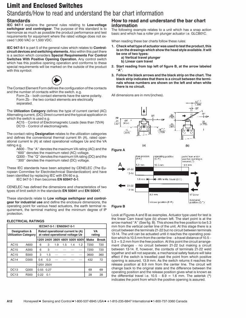
StandardsIEC 947-1 explains the general rules relating to Low-voltageswitchgear and controlgear. The purpose of this standard is toharmonize as much as possible the product performance and testrequirements for equipment where the rated voltage does not ex-ceed 1,000 VAC or 1,500 VDC.
IEC 947-5-1 is part 5 of the general rules which relates to Control-circuit devices and switching elements. Also within this part thereis a section which considers Special Requirements For ControlSwitches With Positive Opening Operation. Any control switchwhich has this positive opening operation and conforms to thesespecial requirements will be marked on the outside of the productwith this symbol:
The Contact Element Form defines the configuration of the contactsand the number of contacts within the switch. e.g.
Form Za – both contact elements have the same polarity.Form Zb – the two contact elements are electricallyseparated.
The Utilization Category defines the type of current carried (AC)Alternating current, (DC) Direct current and the typical application inwhich the switch is used e.g.
AC15 – Control of Electromagnetic Loads (less than 72VA)DC13 – Control of electromagnets.
The contact rating Designation relates to the utilization categoriesand defines the conventional thermal current lth (A), rated oper-ational current le (A) at rated operational voltages Ue and the VArating e.g.
A600 – The ‘‘A’’ denotes the maximum VA rating (AC) and the‘‘600’’ denotes the maximum rated (AC) voltage.Q300 – The ‘‘Q’’ denotes the maximum VA rating (DC) and the‘‘300’’ denotes the maximum rated (DC) voltage.
These IEC standards have been adopted by CENELEC (The Eu-ropean Commitee for Electrotechnical Standardization) and havebeen identified by replacing IEC with EN 60 e.g.
IEC 947-5-1 then becomes EN 60947-5-1.
CENELEC has defined the dimensions and characteristics of twotypes of limit switch in the standards EN 50041 and EN 50047.
These standards relate to Low voltage switchgear and control-gear for industrial use and define the enclosure dimensions, theoperating point for various head actuators, the earth terminal re-quirement, the terminal marking and the minimum degree of IPprotection.
ELECTRICAL RATINGSIEC947-5-1 / EN60947-5-1
Designation & Rated operational current le (A) VAUtilization Category at rated operational voltage Ue rating
120V 240V 380V 480V 500V 600V Make Break
AC15 A600 6 3 1.9 1.5 1.4 1.2 7200 720
AC15 A300 6 3 — — — — 7200 720
AC15 B300 3 1.5 — — — — 3600 360
AC14 D300 0.6 0.3 — — — — 432 72
125V 250V
DC13 Q300 0.55 0.27 69 69
DC13 R300 0.22 0.1 28 28
How to read and understand the bar chartinformationThe following example relates to a unit which has a snap actionbasic and which has a roller pin plunger actuator i.e. GLCB01C.
When reading these bar charts follow these rules:1. Check what type of actuator was used to test the product, this
is on the drawings which show the head style available. It willbe one of two types:
a) Vertical travel plungerb) Linear cam travel
2. Start reading from top left of figure B, at the arrow labeled‘‘A’’.
3. Follow the black arrows and the black strip on the chart. Theblack strip indicates that there is a circuit between the termi-nals whose numbers are shown on the left and when whitethere is no circuit.
All dimensions are in mm/(inches).
Figure A
Figure B
Look at Figures A and B as examples. Actuator type used for test isthe linear Cam travel type (b) shown left. The start point is at thearrow marked ‘‘A’’ (See fig. B). This shows the free position to be 5.3mm from the vertical center line of the unit. At this stage there is acircuit between the terminals 21-22 but no circuit between terminals13-14. The unit can be actuated until it reaches the operating posi-tion which is 10.5 mm from the center line – a travel distance of 10.5 –5.3 = 5.2 mm from the free position. At this point the circuit arrange-ment changes – no circuit between 21-22 but making a circuitbetween 13-14. If, however, the contacts of terminals 21-22 weldtogether and will not separate, a mechanical safety feature will takeeffect if the switch is travelled past the point from which positiveopening is assured, 13.9 mm. As the switch returns it reaches therelease position at 8.9 mm from the center line. The circuit willchange back to the original state and the difference between theoperating position and the release position gives what is known asthe differential travel i.e. 10.5 – 8.9 = 1.6 mm. The asterisk (*)indicates the point from which the positive opening is assured.

Limit and Enclosed SwitchesDegree of Protection
Honeywell 1 Sensing and Control 1 1-800-537-6945 USA 1 F1-815-235-6847 International 1 1-800-737-3360 Canada A13
IP ClassificationThe IEC 529 standard describes a system for classifying the degreeof protection provided by the enclosures of electrical equipment.The level of protection given by the enclosure is indicated by the IPcode.This code system uses the letters ‘‘IP’’ (International Protection)followed by up to four digits. Normally only the first two digits areused.
IP 1stDigit
2ndDigit
3rdDigit
4thDigit
The first digit is numerical and indicates the level of protection withinthe enclosure against the ingress of solid foreign objects and ac-cess to hazardous parts by persons.The second digit is also numerical and indicates the level of protec-tion against the ingress of WATER into the enclosure.The third digit is a letter and indicates a higher level of protection forpersons against access to hazardous parts.The fourth digit is also a letter and is used in exceptional cases forsupplementary information.If the first or second digit is not required to be specified, then it isreplaced by the letter ‘‘X’’ (‘‘XX’’ if both digits are not required).While the tables below serve as a guide to the level of protection,Honeywell recommends that customers refer to the full official IECspecification for the exact definitions. If in doubt about the degree ofprotection required for a particular application, please consult yourlocal Honeywell office.
Note:The IEC 529 standard does not relate to protection against rust,corrosion, icing or corrosive solvents (e.g. cutting fluids) and thatproduct coded IP 67 may not necessarily meet IP 66 requirements.
First Digit Protection against ingress of solid objects
IP TEST0 no protection1 protected against solid objects with a diameter greater
than 50 mm.2 protected against solid objects with a diameter greater
than 12 mm.3 protected against solid objects with a diameter greater
than 2.5 mm.4 protected against solid objects with a diameter greater
than 1 mm.5 protected against dust-limited ingress (no harmful
deposit)6 totally protected against dust
Second Digit Protection against ingress of water
IP TEST0 no protection1 protected against vertically falling drops of water.2 protected against vertically falling drops of water when
the enclosure is tilted at an angle up to 15 degrees.3 protected against water sprayed at an angle of 60
degrees from the vertical4 protected against splashing water from all directions –
limited ingress (no harmful effects)5 protected against low pressure jets of water from all
directions – limited ingress permitted6 protected against powerful jets of water from all
directions – limited ingress permitted7 protected against the effects of temporary immersion in
water8 protected against the effects of continuous immersion in
water
NEMA Classification (USA)NEMA (National Electrical Manufacturer’s Association) pre-pares standards which define a product, process or procedure withreference to one or more of the following: nomenclature, composi-tion, construction, dimensions, tolerances, safety, operating char-acteristics, performance, quality, electrical rating, testing and theservice for which designed.This standard provides degrees of protection for Enclosures forElectrical Equipement (1000 Volts Maximum) similar to that of theIEC 529 standard. The reference standard herein reflects the latestdata in the NEMA Standards Publication when this information wentto print.
Non-hazardous locationsType 1enclosures are intended for indoor use primarily to provide adegree of protection against contact with the enclosed equipment.Type 3 enclosures are intended for outdoor use primarily to pro-vide a degree of protection against windblown dust, rain, sleet, andexternal ice formation.Type 4 enclosures are intended for indoor or outdoor use primarilyto provide a degree of protection against windblown dust and rain,splashing water, and hose-directed water.Type 4X enclosures are intended for indoor or outdoor use primar-ily to provide a degree of protection against corrosion, windblowndust and rain, splashing water, and hose-directed water.Type 6 enclosures are intended for indoor or outdoor use primarilyto provide a degree of protection against the entry of water duringoccasional temporary submersion at a limited depth.Type 6P enclosures are intended for indoor or outdoor use primar-ily to provide a degree of protection against the entry of water duringprolonged submersion at a limited depth.Type 12 enclosures are intended for indoor use primarily to providea degree of protection against dust, falling dirt, and dripping non-corrosive liquids.Type 13 enclosures are intended for indoor use primarily to providea degree of protection against dust, spraying water, oil and non-corrosive coolant.Note: Enclosures are based, in general, on the broad definitionsoutlined in NEMA Standards. Therefore, it will be necessary toascertain that a particular enclosure will be adequate when exposedto the specific conditions that might exist in intended applications.Except as might otherwise be noted, all references to productsrelative to NEMA enclosure type are based on Honeywell evaluationand Underwriter’s Laboratory (UL) tested.This NEMA Standards Publication does test for environmental con-ditions such as corrosion, rust, icing, oil, and coolants. The IEC 529does not, and does not specify degree of protection against me-chanical damage of equipment. For this reason, and because thetests and evaluations for other characteristics are not identical, theIEC Enclosure Classification Designations cannot be exactly equa-ted with NEMA Enclosure Type Numbers.
Lim
it/En
closed
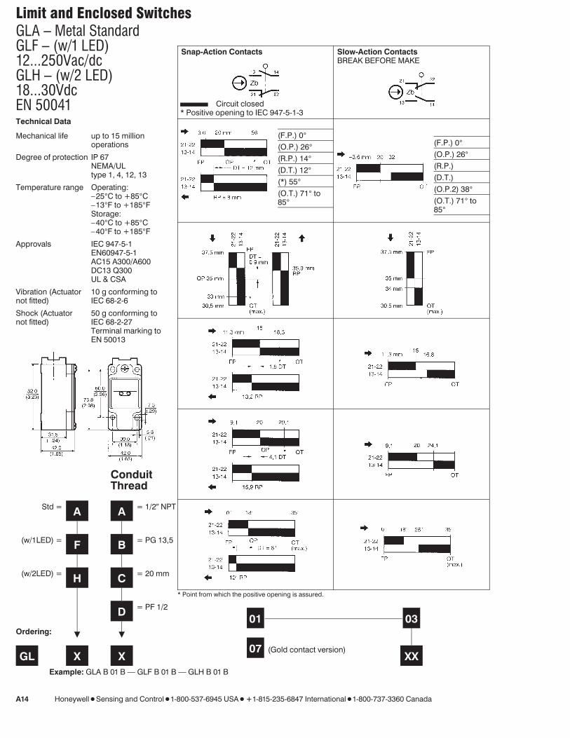
Limit and Enclosed SwitchesGLA – Metal StandardGLF – (w/1 LED)12...250Vac/dcGLH – (w/2 LED)18...30VdcEN 50041
A14 Honeywell 1 Sensing and Control 1 1-800-537-6945 USA 1 F1-815-235-6847 International 1 1-800-737-3360 Canada
Technical Data
Mechanical life up to 15 millionoperations
Degree of protection IP 67NEMA/ULtype 1, 4, 12, 13
Temperature range Operating:–25°C to +85°C–13°F to +185°FStorage:–40°C to +85°C–40°F to +185°F
Approvals IEC 947-5-1EN60947-5-1AC15 A300/A600DC13 Q300UL & CSA
Vibration (Actuatornot fitted)
10 g conforming toIEC 68-2-6
Shock (Actuatornot fitted)
50 g conforming toIEC 68-2-27Terminal marking toEN 50013
Snap-Action Contacts
Circuit closed* Positive opening to IEC 947-5-1-3
Slow-Action ContactsBREAK BEFORE MAKE
(F.P.) 0°(O.P.) 26°(R.P.) 14°(D.T.) 12°(*) 55°(O.T.) 71° to85°
(F.P.) 0°(O.P.) 26°(R.P.)(D.T.)(O.P.2) 38°(O.T.) 71° to85°
* Point from which the positive opening is assured.
01 03
X07 (Gold contact version)
Ordering:
GL X X XXExample: GLA B 01 B — GLF B 01 B — GLH B 01 B
ConduitThread
Std = A A = 1/2N NPT
(w/1LED) = F B = PG 13,5
(w/2LED) = H C = 20 mm
D = PF 1/2
X X

Limit and Enclosed Switches
Honeywell 1 Sensing and Control 1 1-800-537-6945 USA 1 F1-815-235-6847 International 1 1-800-737-3360 Canada A15
Slow-Action ContactsMAKE BEFORE BREAK
Snap-Action ContactsDOUBLE POLE
Actuator Types
(F.P.) 0°(O.P.) 26°(R.P.)(D.T.)(O.P.2) 38°(O.T.) 71° to85°
(F.P.) 0°(O.P.) 26°(R.P.) 14°(D.T.) 12°(*) 55°(O.T.) 71° to85°
(GLA) (GLF, GLH)
04 20 or 24
XXX
A1BAdditional
levers available(see page A24)
B
C
D
E7B
X
Lim
it/En
closed

Limit and Enclosed SwitchesGLB – Metal Plug-inGLG – (w/1LED) 12...250Vac/dcGLJ – (w/2LED) 18...30VdcEN 50041
A16 Honeywell 1 Sensing and Control 1 1-800-537-6945 USA 1 F1-815-235-6847 International 1 1-800-737-3360 Canada
Technical Data
Mechanical life up to 15 million operations
Degree of protection IP 67NEMA/UL type 1, 4, 12, 13
Temperature range Operating:–25°C to +85°C–13°F to +185°FStorage:–40°C to +85°C–40°F to +185°F
Approvals IEC 947-5-1EN60947-5-1AC15 A300/A600DC13 Q300UL & CSA
Vibration (Actuator not fitted) 10 g conforming to IEC 68-2-6
Shock (Actuator not fitted) 50 g conforming to IEC 68-2-27Terminal marking to EN 50013
Snap-Action Contacts
Circuit closed* Positive opening to IEC 947-5-1-3
(F.P.) 0°(O.P.) 26°(R.P.) 14°(D.T.) 12°(*) 55°(O.T.) 71° to85°
* Point from which the positive opening is assured.(GLB only)
02
Ordering:
GL X XExample: GLB B 02 B — GLG B 12 B — GLJ B 13 B
ConduitThread
Plug-in = B A = 1/2N NPT
(w/1LED) = G B = PG 13,5
(w/2LED) = J C = 20 mm
D = PF 1/2
X X

Limit and Enclosed Switches
Honeywell 1 Sensing and Control 1 1-800-537-6945 USA 1 F1-815-235-6847 International 1 1-800-737-3360 Canada A17
Snap-Action Contacts Snap-Action Contacts Actuator Types
(F.P.) 0°(O.P.) 26°(R.P.) 14°(D.T.) 12°(*) 55°(O.T.) 71° to85°
(F.P.) 0°(O.P.) 26°(R.P.) 14°(D.T.) 12°(*) 55°(O.T.) 71° to85°
(GLG only) (GLJ only)
12 13
X
XX XXX
A1BAdditional
levers available(see page A24)
B
C
D
E7B
X
Lim
it/En
closed

Limit and Enclosed SwitchesGLCEN 50047Metal standard
A18 Honeywell 1 Sensing and Control 1 1-800-537-6945 USA 1 F1-815-235-6847 International 1 1-800-737-3360 Canada
Technical Data
Mechanical life up to 15 million operations
Degree of protection IP 66NEMA/UL type 1, 4, 12, 13
Temperature range Operating:–25°C to +85°C–13°F to +185°FStorage:–40°C to +85°C–40°F to +185°F
Approvals IEC 947-5-1EN60947-5-1AC15 A300DC13 Q300UL & CSA
Vibration (Actuator not fitted) 10 g conforming to IEC 68-2-6
Shock (Actuator not fitted) 50 g conforming to IEC 68-2-27Terminal marking to EN 50013
Snap-Action Contacts
Circuit closed* Positive opening to IEC 947-5-1-3
(F.P.) 0°(O.P.) 26°(R.P.) 14°(D.T.) 12°(*) 55°(O.T.) 61° to 75°
* Point from which the positive opening is assured.
01
Ordering:
GLC XExample: GLC B 01 B
Conduit Thread
A = 1/2N NPT adapter
B = PG 13,5
C = 20 mm
D = PF 1/2
X

Limit and Enclosed Switches
Honeywell 1 Sensing and Control 1 1-800-537-6945 USA 1 F1-815-235-6847 International 1 1-800-737-3360 Canada A19
Slow-Action ContactsBREAK BEFORE MAKE
Slow-Action ContactsMAKE BEFORE BREAK
Actuator Types
(F.P.) 0°(O.P.) 26°(R.P.)(D.T.)(O.P.2) 39°(O.T.) 61° to75°
(F.P.) 0°(O.P.) 26°(R.P.)(D.T.)(O.P.2) 39°(O.T.) 61° to75°
03 04
X
XX XXX
A1BAdditional
levers available(see page A24)
B
C
D
E7B
X
Lim
it/En
closed
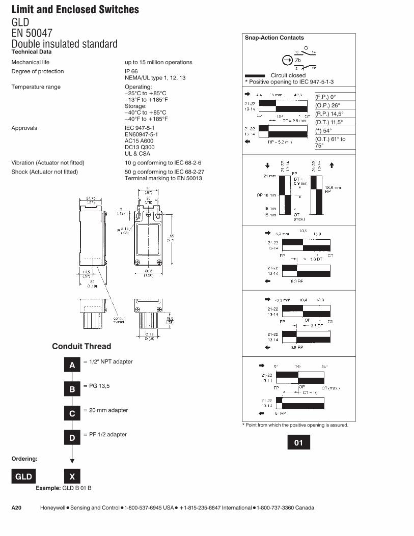
Limit and Enclosed SwitchesGLDEN 50047Double insulated standard
A20 Honeywell 1 Sensing and Control 1 1-800-537-6945 USA 1 F1-815-235-6847 International 1 1-800-737-3360 Canada
Technical Data
Mechanical life up to 15 million operations
Degree of protection IP 66NEMA/UL type 1, 12, 13
Temperature range Operating:–25°C to +85°C–13°F to +185°FStorage:–40°C to +85°C–40°F to +185°F
Approvals IEC 947-5-1EN60947-5-1AC15 A600DC13 Q300UL & CSA
Vibration (Actuator not fitted) 10 g conforming to IEC 68-2-6
Shock (Actuator not fitted) 50 g conforming to IEC 68-2-27Terminal marking to EN 50013
Snap-Action Contacts
Circuit closed* Positive opening to IEC 947-5-1-3
(F.P.) 0°(O.P.) 26°(R.P.) 14,5°(D.T.) 11,5°(*) 54°(O.T.) 61° to75°
* Point from which the positive opening is assured.
01
Ordering:
GLD XExample: GLD B 01 B
Conduit Thread
A = 1/2N NPT adapter
B = PG 13,5
C = 20 mm adapter
D = PF 1/2 adapter
X

Limit and Enclosed Switches
Honeywell 1 Sensing and Control 1 1-800-537-6945 USA 1 F1-815-235-6847 International 1 1-800-737-3360 Canada A21
Slow-Action ContactsBREAK BEFORE MAKE
Slow-Action ContactsMAKE BEFORE BREAK
Actuator Types
(F.P.) 0°(O.P.) 26°(R.P.)(D.T.)(O.P.2) 39°(O.T.) 61° to75°
(F.P.) 0°(O.P.) 26°(R.P.)(D.T.)(O.P.2) 39°(O.T.) 61° to75°
03 04
X
XX XXX
A1BAdditional
levers available(see page A24)
B
C
D
E7B
X
Lim
it/En
closed
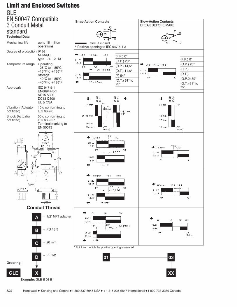
Limit and Enclosed SwitchesGLEEN 50047 Compatible3 Conduit Metalstandard
A22 Honeywell 1 Sensing and Control 1 1-800-537-6945 USA 1 F1-815-235-6847 International 1 1-800-737-3360 Canada
Technical Data
Mechanical life up to 15 millionoperations
Degree of protection IP 66NEMA/ULtype 1, 4, 12, 13
Temperature range Operating:–25°C to +85°C–13°F to +185°FStorage:–40°C to +85°C–40°F to +185°F
Approvals IEC 947-5-1EN60947-5-1AC15 A300DC13 Q300UL & CSA
Vibration (Actuatornot fitted)
10 g conforming toIEC 68-2-6
Shock (Actuatornot fitted)
50 g conforming toIEC 68-2-27Terminal marking toEN 50013
Snap-Action Contacts
Circuit closed* Positive opening to IEC 947-5-1-3
Slow-Action ContactsBREAK BEFORE MAKE
(F.P.) 0°(O.P.) 26°(R.P.) 14,5°(D.T.) 11,5°(*) 54°(O.T.) 61° to75°
(F.P.) 0°(O.P.) 26°(R.P.)(D.T.)(O.P.2) 39°(O.T.) 61° to75°
* Point from which the positive opening is assured.
01 03
X
Ordering:
GLE X XXExample: GLE B 01 B
Conduit Thread
A = 1/2N NPT adapter
B = PG 13,5
C = 20 mm
D = PF 1/2
X

Limit and Enclosed Switches
Honeywell 1 Sensing and Control 1 1-800-537-6945 USA 1 F1-815-235-6847 International 1 1-800-737-3360 Canada A23
Slow-Action ContactsMAKE BEFORE BREAK
Snap-Action ContactsDOUBLE POLE
Actuator Types
(F.P.) 0°(O.P.) 26°(R.P.)(D.T.)(O.P.2) 39°(O.T.) 61° to75°
(F.P.) 0°(O.P.) 26°(R.P.) 18°(D.T.) 8°(*) 54°(O.T.) 61° to75°
04 24
XXX
A1BAdditional
levers available(see page A24)
B
C
D
E7B
X
Lim
it/En
closed

Limit and Enclosed SwitchesAdditional Lever Types
A24 Honeywell 1 Sensing and Control 1 1-800-537-6945 USA 1 F1-815-235-6847 International 1 1-800-737-3360 Canada
For use with all Side Rotary Head Style.Figure 1 illustrates Miniature Din lever types conforming to EN 50047 while Figure 2illustrates Standard Din lever types which conform to EN 50041.
All dimensions are in mm/(inches).
GLC, GLD, GLE (EN 50047)
Side Rotary Roller LeverA1A Plastic RollerA1B Metal Roller
Side Rotary Adjustable LeverA2A Plastic RollerA2B Metal Roller
Side Rotary Adjustable RodA4J Metal Rod Head
Offset Side Rotary Roller LeverA5A Plastic RollerA5B Metal Roller Head
Side Rotary Conveyor LeverA9A Ceramic Roller
Figure 1
GLA, GLB, GLF, GLH, GLG, GLJ (EN 50041)
Side Rotary Roller LeverA1A Plastic RollerA1B Metal Roller
Side Rotary Adjustable LeverA2A Plastic RollerA2B Metal Roller
Offset Side Rotary Roller LeverA5A – Plastic RollerA5B – Metal Roller
Side Rotary Adjustable RodA4J Metal Rod Head
Figure 2

Limit and Enclosed SwitchesSpare Parts for the GLS Series
Honeywell 1 Sensing and Control 1 1-800-537-6945 USA 1 F1-815-235-6847 International 1 1-800-737-3360 Canada A25
To order spare parts for your particular GLS simply use the GLS number on the front of the switch to identify the construction used andtherefore the spare part you need.
For Example: The part No: GLAB01E7BGLA B 01 E7B
Wobble Head01 Basic Snap Action
B Thread PG13.5EN 50041 Body
For Example: The part No: GLDC04A1BGLD C 04 A1B
Fixed Side Rotary Steel Roller04 Make Before Break Slow Action
C Thread 20 mmEN 50047 Body
From the tables below it is possible to obtain replacement Basic Switches, Heads, Actuators, Levers and LED Assemblies.
Note: Spare parts should only be used to replace parts on existing listings. Honeywell accepts no liability for parts used in combinations notrecognized by Honeywell as valid listings.
Basic Switches
Body Basic SwitchType 01 02 03 04 12 13 20 24
GLA GLZ301 GLZ303 GLZ304 GLZ320
GLB GLZ3021
GLC GLZ301 GLZ303 GLZ304
GLD GLZ301 GLZ303 GLZ304
GLE GLZ301 GLZ303 GLZ304 GLZ324
GLF GLZ301 GLZ303 GLZ304
GLG GLZ3121
GLH GLZ301 GLZ303 GLZ304
GLJ GLZ3131
Note 1: For these spares you will receive the front of the body with no head. To replace the faulty switch/LED assembly remove the old body and old head. Retrofit the headonto the replacement and plug in the spare switch/LED assembly into the old base.
Heads
Body Head TypesType A B C D E7A E7B E7D K8A K8B K8C
GLA GLZ1AA GLZ1AB GLZ1AC GLZ1AD GLZ1AE7A GLZ1AE7B GLZ1AE7D GLZ1AK8A GLZ1AK8B GLZ1AK8C
GLB GLZ1AA GLZ1AB GLZ1AC GLZ1AD GLZ1AE7A GLZ1AE7B GLZ1AE7D GLZ1AK8A GLZ1AK8B GLZ1AK8C
GLC N/A N/A N/A N/A N/A N/A N/A N/A N/A
GLD N/A N/A N/A N/A N/A N/A N/A N/A N/A
GLE N/A N/A N/A N/A N/A N/A N/A N/A N/A
GLF GLZ1AA GLZ1AB GLZ1AC GLZ1AD GLZ1AE7A GLZ1AE7B GLZ1AE7D GLZ1AK8A GLZ1AK8B GLZ1AK8C
GLG GLZ1AA GLZ1AB GLZ1AC GLZ1AD GLZ1AE7A GLZ1AE7B GLZ1AE7D GLZ1AK8A GLZ1AK8B GLZ1AK8C
GLH GLZ1AA GLZ1AB GLZ1AC GLZ1AD GLZ1AE7A GLZ1AE7B GLZ1AE7D GLZ1AK8A GLZ1AK8B GLZ1AK8C
GLJ GLZ1AA GLZ1AB GLZ1AC GLZ1AD GLZ1AE7A GLZ1AE7B GLZ1AE7D GLZ1AK8A GLZ1AK8B GLZ1AK8C
Levers / Actuators (For GLZ1AA Head Type Only (side rotary))
Body Lever Actuator TypeType 1A 1B 2A 2B 4J 5B
GLA GLZ51A GLZ51B GLZ52A GLZ52B GLZ54J GLZ55B
GLB GLZ51A GLZ51B GLZ52A GLZ52B GLZ54J GLZ55B
GLC N/A N/A N/A N/A N/A N/A
GLD N/A N/A N/A N/A N/A N/A
GLE N/A N/A N/A N/A N/A N/A
GLF GLZ51A GLZ51B GLZ52A GLZ52B GLZ54J GLZ55B
GLG GLZ51A GLZ51B GLZ52A GLZ52B GLZ54J GLZ55B
GLH GLZ51A GLZ51B GLZ52A GLZ52B GLZ54J GLZ55B
GLJ GLZ51A GLZ51B GLZ52A GLZ52B GLZ54J GLZ55B
Lim
it/En
closed

Limit and Enclosed Switches
A26 Honeywell 1 Sensing and Control 1 1-800-537-6945 USA 1 F1-815-235-6847 International 1 1-800-737-3360 Canada
LED AssembliesBody LED-Assembly TYPEType 1-LED 2-LED
GLA
GLB
GLC
GLD
GLE
GLF GLZ6F
GLG
GLH GLZ6H
GLJ
Parts DescriptionHeads
GLZ1AA Side Rotary HeadGLZ1AB Top Pin Plunger HeadGLZ1AC Top Roller Plunger HeadGLZ1AD Roller Arm HeadGLZ1AE7A Plastic Wobble Stick Head AssemblyGLZ1AE7B Coil Wobble Stick Head AssemblyGLZ1AE7D Coil Whisker Head AssemblyGLZ1AK8A 140mm Cat’s Whisker Head AssemblyGLZ1AK8B 190mm Cat’s Whisker Head AssemblyGLZ1AK8C Cat’s Whisker Head Assembly
Basics
GLZ301 Snap Action SPDT (01)GLZ302 Snap Action SPDT Plug-In (02) see Note 1 on page A25GLZ303 SPDT Break Before Make (03)GLZ304 SPDT Make Before Break (04)GLZ312 Snap Action SPDT 1 LED Plug-In (12) see Note 1 on page A25GLZ313 Snap Action SPDT 2 LED Plug-In (13) see Note 1 on page A25GLZ320 Snap Action DPDT (20)GLZ324 Snap Action DPDT for 3 Conduit (24)
Actuators
GLZ51A Side Rotary Fixed Lever Nylon Roller ActuatorGLZ51B Side Rotary Fixed Lever Steel Roller ActuatorGLZ52A Side Rotary Adjustable Lever Nylon Roller ActuatorGLZ52B Side Rotary Adjustable Lever Steel Roller ActuatorGLZ54J Side Rotary Adjustable Rod ActuatorGLZ55B Side Rotary Fixed Offset Lever Steel Roller
LED Assemblies
GLZ6F Spare 1 LED Assembly for GLF...GLZ6H Spare 2 LED Assembly for GLH...
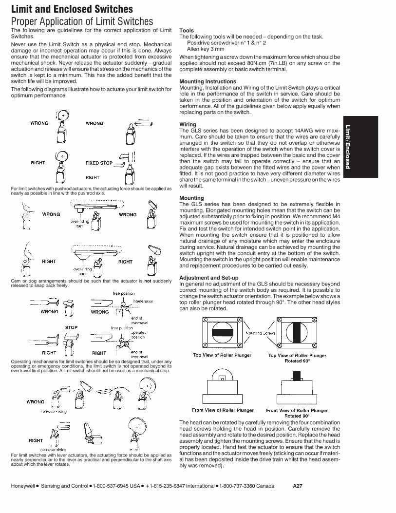
Limit and Enclosed SwitchesProper Application of Limit Switches
Honeywell 1 Sensing and Control 1 1-800-537-6945 USA 1 F1-815-235-6847 International 1 1-800-737-3360 Canada A27
The following are guidelines for the correct application of LimitSwitches.Never use the Limit Switch as a physical end stop. Mechanicaldamage or incorrect operation may occur if this is done. Alwaysensure that the mechanical actuator is protected from excessivemechanical shock. Never release the actuator suddenly – gradualactuation and release will ensure that stress on the mechanics of theswitch is kept to a minimum. This has the added benefit that theswitch life will be improved.The following diagrams illustrate how to actuate your limit switch foroptimum performance.
For limit switches with pushrod actuators, the actuating force should be applied asnearly as possible in line with the pushrod axis.
Cam or dog arrangements should be such that the actuator is not suddenlyreleased to snap back freely.
Operating mechanisms for limit switches should be so designed that, under anyoperating or emergency conditions, the limit switch is not operated beyond itsovertravel limit position. A limit switch should not be used as a mechanical stop.
For limit switches with lever actuators, the actuating force should be applied asnearly perpendicular to the lever as practical and perpendicular to the shaft axisabout which the lever rotates.
ToolsThe following tools will be needed – depending on the task.
Posidrive screwdriver n° 1 & n° 2Allen key 3 mm
When tightening a screw down the maximum force which should beapplied should not exceed 80N.cm (7in.LB) on any screw on thecomplete assembly or basic switch terminal.
Mounting InstructionsMounting, Installation and Wiring of the Limit Switch plays a criticalrole in the performance of the switch in service. Care should betaken in the position and orientation of the switch for optimumperformance. All of the guidelines given below apply equally whenreplacing parts on the switch.
WiringThe GLS series has been designed to accept 14AWG wire maxi-mum. Care should be taken to ensure that the wires are carefullyarranged in the switch so that they do not overlap or otherwiseinterfere with the operation of the switch when the switch cover isreplaced. If the wires are trapped between the basic and the coverthen the switch may fail to operate correctly – ensure that anadequate gap exists between the fitted wires and the cover whenfitted. It is not good practice to have very different diameter wiresshare the same terminal in the switch – uneven pressure on the wireswill result.
MountingThe GLS series has been designed to be extremely flexible inmounting. Elongated mounting holes mean that the switch can beadjusted substantially prior to fixing in position. We recommend M4maximum screws be used for mounting the switch in its application.Fix and test the switch for intended switch point in the application.When mounting the switch ensure that it is positioned to allownatural drainage of any moisture which may enter the enclosureduring service. Natural drainage can be achieved by mounting theswitch upright with the conduit entry at the bottom of the switch.Mounting the switch in the upright position will enable maintenanceand replacement procedures to be carried out easily.
Adjustment and Set-upIn general no adjustment of the GLS should be necessary beyondcorrect mounting of the switch body as required. It is possible tochange the switch actuator orientation. The example below shows atop roller plunger head rotated through 90°. The other head stylescan also be rotated.
The head can be rotated by carefully removing the four combinationhead screws holding the head in position. Carefully remove thehead assembly and rotate to the desired position. Replace the headassembly and tighten the mounting screws. Ensure that the head isproperly located. Hand test the actuator to ensure that the switchfunctions and the actuator moves freely (sticking can occur if materi-al has been deposited inside the drive train whilst the head assem-bly was removed).
Lim
it/En
closed
Limit and Enclosed Switches
A28 Honeywell 1 Sensing and Control 1 1-800-537-6945 USA 1 F1-815-235-6847 International 1 1-800-737-3360 Canada
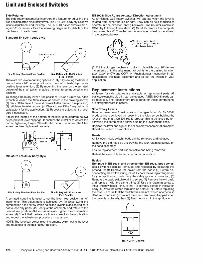
Side RotariesThe side rotary assemblies incorporate a feature for adjusting thefree position of the side rotary lever. The EN 50041body style allowsinfinite adjustment and reclamp. The EN 50047 style allows clamp-ing in 10° increments. See the following diagrams for details of themechanism in each case.
Standard EN 50041 body style
There are two lever mounting options: (1) By fully seating the lever inone of the four 90° detent positions on the shaft hub which providespositive lever retention; (2) By mounting the lever on the serratedportion of the shaft (which enables the lever to be mounted in anyposition).To change the rotary lever’s free position: (1) Use a 3 mm hex Allenwrench to loosen the Allen screw, as shown in the drawing above;(2) Back off the lever 2 mm and move it to the desired free position;(3) retighten the Allen screw; (4) Check to see if the free position issatisfactory for the application; (5) Repeat the adjustment proce-dure if necessary.A teller tab located at the bottom of the lever (see diagram below)helps prevent lever slippage. It enables the installer to detect thecorrect tightening torque. When this tab cannot be moved, the Allenscrew has been tightened properly.
Miniature EN 50047 body style
A serrated coupling is used to set the lever free position in 10°increments. This adjustment is achieved by: (1) Unscrewing thecombination head screw which holds the lever in place, taking carenot to lose any parts; (2) Readjust the assembly and rotate to thedesired free position; (3) Re-assemble and tighten the combinationscrew. (4) Check that the free position is correct for the applicationand repeat the adjustment procedure if necessary.NOTE: The lever can be set in 90° increments by removing the leverand rotating it to the desired 90° position.
EN 50041 Side Rotary Actuator Direction AdjustmentAs furnished, GLS rotary switches will operate when the lever isrotated from either the left or right. They can be field modified tooperate in one direction only (Clockwise CW; Counter clockwiseCCW) by following these steps: (1) Carefully remove the completehead assembly; (2) Turn the head assembly upside down as shownin the drawing below.
(3) Pull the plunger mechanism out and rotate it through 90° degreeincrements until the alignment tab points to the desired function(CW, CCW, or CW and CCW). (4) Push plunger mechanism in. (5)Reassemble the head assembly and re-test the switch in yourapplication.
Replacement InstructionsAll levers for side rotaries are available as replacment parts. Allbasics, except the plug-in, can be replaced. All EN 50041heads canbe replaced. The replacement procedures for these componentsare straightforward in nature.
Side Rotary LeversRemove the old lever from the product being replaced. On EN 50041product this is achieved by loosening the Allen screw holding thelever on the shaft. On EN 50047 product this is achieved by un-screwing the combination screw holding the lever on the shaft.Replace the lever and tighten the Allen screw or combination screw.Retest the switch in its application.
HeadsAll EN 50041 style switch heads can be removed and replaced.Remove the old head by unscrewing the four retaining screws onthe head assembly.Ensure replacement part is identical to one being removed.Re-test the assembly and ensure correct operation.
BasicsNon plug-in EN 50041 and three conduit EN 50047 body styles.Basic switches can be removed and replaced by following thisprocedure: (1) Remove the cover from the body; (2) Before dis-connecting the switch wiring, carefully note the wiring arrangementfor your application, particularly the safety ground connection; (3)Remove the basic switch retaining screw; (4) Remove the old basicand replace it with the same thing; (5) Use the retaining screw toinstall the new basic – ensure that it is correctly seated in the switchbody; (6) Wire the switch terminals as before; (7) Before replacingthe cover – ensure that the switch wires are not twisted or otherwiselifted from the basic (to prevent them from becoming trapped whenthe cover is replaced); then (8) Test the switch in the application.
Limit and Enclosed Switches
Honeywell 1 Sensing and Control 1 1-800-537-6945 USA 1 F1-815-235-6847 International 1 1-800-737-3360 Canada A29
Miniature EN 50047 body styleUse same replacement procedure as above except that no retainingscrew is involved. The basic switch is secured in the miniaturehousings by a press fit. To remove an inoperative switch, merelygrasp the basic firmly and pull it out of the housing. Insert the newswitch in its place. Then wire the new basic as before and test it in theapplication.
Plug-in EN 50041 body styleThe switch enclosure portion of this two-piece body style plugs intoa pre-wired terminal block mounted in the application. Replacementis accomplished by unplugging the old switch enclosure and plug-ging-in a new switch enclosure (basics are permanently staked inthe switch enclosure).
LED WiringThe GLF, GLG, GLH and GLJ versions of GLS (EN 50041) comecomplete with LED indicators. These indicators can be wired in avariety of ways. The standard adopted in the GLG (1 LED Plug-inbody) and in the GLJ (2 LED Plug-in body) versions is to use green toindicate power available and yellow to indicate operation. Operationcan indicate actuator free or actuator operated depending on thewireing arrangement employed.The table below indicates the body styles and indicators offered.
Body Function Spec.
GLF... 1 LED 12 → 250V AC and DC Less than1,5mA draw
GLG... 1 LED plug-in 12 → 250V AC and DC Less than1,5mA draw
GLH... 2 LED 18 → 30V DC 7mA typ. current draw
GLJ... 2 LED plug-in 18 → 30V DC 7mA typ. current draw
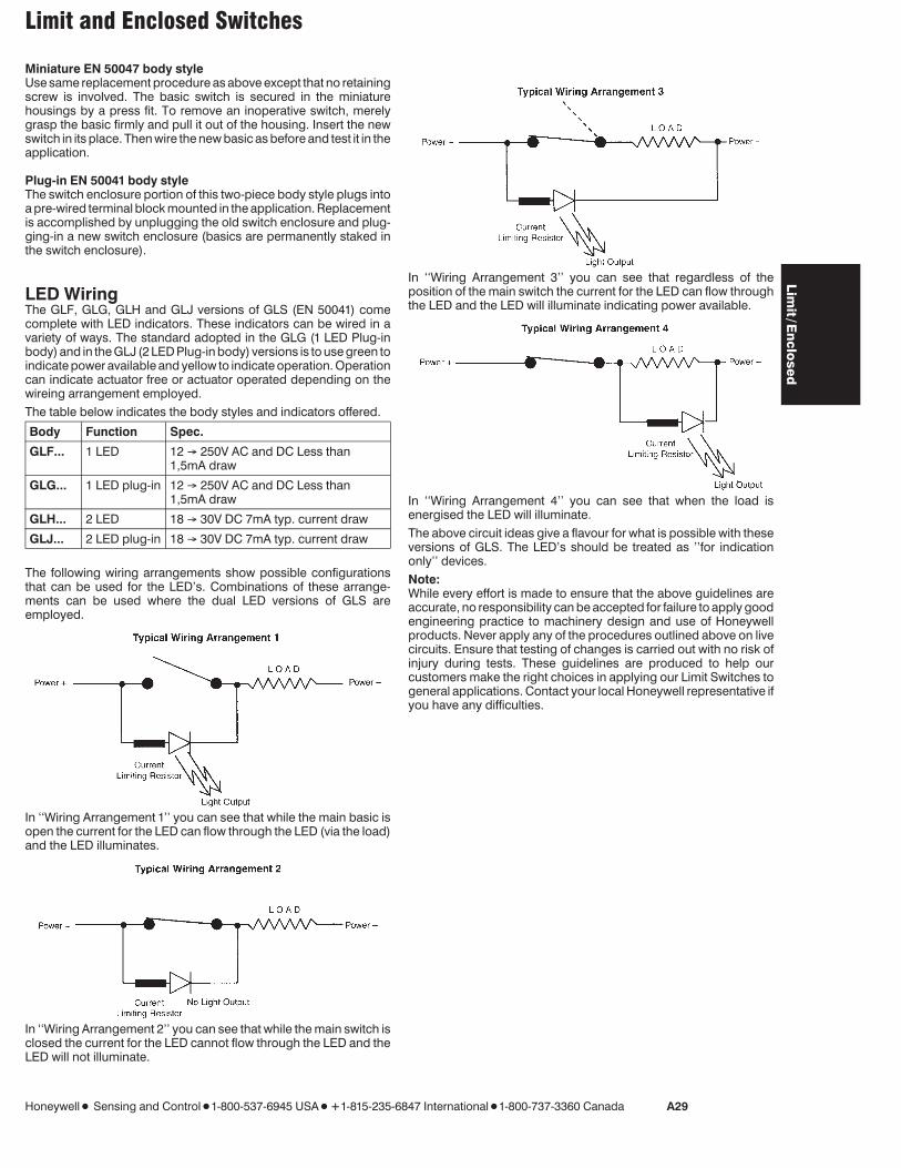
The following wiring arrangements show possible configurationsthat can be used for the LED’s. Combinations of these arrange-ments can be used where the dual LED versions of GLS areemployed.
In ‘‘Wiring Arrangement 1’’ you can see that while the main basic isopen the current for the LED can flow through the LED (via the load)and the LED illuminates.
In ‘‘Wiring Arrangement 2’’ you can see that while the main switch isclosed the current for the LED cannot flow through the LED and theLED will not illuminate.
In ‘‘Wiring Arrangement 3’’ you can see that regardless of theposition of the main switch the current for the LED can flow throughthe LED and the LED will illuminate indicating power available.
In ‘‘Wiring Arrangement 4’’ you can see that when the load isenergised the LED will illuminate.The above circuit ideas give a flavour for what is possible with theseversions of GLS. The LED’s should be treated as ’’for indicationonly’’ devices.Note:While every effort is made to ensure that the above guidelines areaccurate, no responsibility can be accepted for failure to apply goodengineering practice to machinery design and use of Honeywellproducts. Never apply any of the procedures outlined above on livecircuits. Ensure that testing of changes is carried out with no risk ofinjury during tests. These guidelines are produced to help ourcustomers make the right choices in applying our Limit Switches togeneral applications. Contact your local Honeywell representative ifyou have any difficulties.
Lim
it/En
closed