· PDF file · 2016-05-13Specifications of WAVE/DSRC Models ... WSM Service...
112
Copyright © 2015 by EstiNet Technologies Inc. All rights reserved www.EstiNet.com GRAPHIC USER INTERFACE (GUI) MANUAL VANET MODULE OF ESTINET SIMULATOR 9.0 V1.0 EstiNet A professional company in Software-Defined Networks (SDN)
Transcript of · PDF file · 2016-05-13Specifications of WAVE/DSRC Models ... WSM Service...

Copyright © 2015 by EstiNet Technologies Inc. All rights reserved www.EstiNet.com
GRAPHIC USER INTERFACE (GUI) MANUAL
VANET MODULE OF ESTINET SIMULATOR 9.0
V1.0
EstiNet
A professional company in
Software-Defined Networks (SDN)

2
Revision History
Rev. Date
Author
Revision Description
1.0 March. 3, 2015
Jackie Chang
Initial version
3
Copyright © 2015 by EstiNet. All rights reserved.
The drawings, specifications and the data contain herein are the exclusive property of EstiNet.
Issued in strict confidence and shall not, without the prior written permission of EstiNet., be
reproduced, copied or used, in parts or as a whole, for any purpose whatsoever, except the
manufacture of articles for EstiNet.
EstiNet reserves the right to make revisions to this document and the product described
herein without obligation to notify any person or entity of any such changes.
Warning
This document is intended for EstiNet’s customer use only. A Non-‐Disclosure Agreement
(NDA) approved by V.P of EstiNet Marketing Department is required to release this document
under any circumstances.
Reviewed By: Date: / /
Approved By: Date: / /
Released By: Date: / /
EstiNet is the registered trademarks of EstiNet Inc.

4
TABLE OF CONTENTS
VANET—Vehicular Ad Hoc Network ................................................................................................................. 5
ITS Network Concept .......................................................................................................................................... 6
Specifications of WAVE/DSRC Models ............................................................................................................... 7
OBUs and RSUs Supported by ESTINET ........................................................................................................... 10
IEEE 802.11p/1609 ........................................................................................................................................... 11
Introduction to OBUs and RSUs ...................................................................................................................... 11
Constructing a Road Structure ......................................................................................................................... 17
Accessing Road Map Files ................................................................................................................................ 20
Adding and Deploying Vehicles ....................................................................................................................... 25
Landmark Addition and Deployment .............................................................................................................. 29
Designation of Landmark Settings for ITS Vehicles ......................................................................................... 32
Settings for and Definition of Vehicle Driving Behavior .................................................................................. 43
Car Profile ......................................................................................................................................................... 43
Car Agent and Signal Agent Programs ............................................................................................................. 48
IEEE 802.11P/1609 Communications Settings ................................................................................................. 51
Provider/User Service Settings ........................................................................................................................ 54
CCH Service Settings ......................................................................................................................................... 70
WSM Service Settings ...................................................................................................................................... 73
WSM and WSM_Forwarding Applications ...................................................................................................... 76
Introduction to the Multi-Interface Car ........................................................................................................... 82
Conclusion ...................................................................................................................................................... 111
References ...................................................................................................................................................... 112

5
VANET—Vehicular Ad Hoc Network
The chapters in this manual explain the concept of the Intelligent Transportation System (ITS)
network and the operation of the wireless access in vehicular environments (WAVE) mode
(802.11p/1609). Diagrams and relevant explanations are then used to illustrate the configuration of
the ITS network in EstiNet. The overall structure of the chapters comprises two perspectives through
which an introduction to the system is provided: 1) the deployment of the ITS road network
infrastructure and the settings for vehicle driving behavior; 2) a user manual for the manipulation
of 802.11p/1609.3/1609.4 service settings from a communication perspective.
The first section includes the types of and an introduction to ITS vehicles currently available from
EstiNet, as well as descriptions of ITS vehicle deployment methods, road network deployment
methods, landmark deployment methods, methods of accessing real-world maps, map capture,
functions related to traffic lights at intersections (agent/module programs), and an introduction to
the agent/module programs controlling vehicle driving behavior. The second section provides
802.119/1609.3 service settings and 1609.4 channel interval settings, including settings for 1609.3
provider, user, WAVE short message (WSM), and control channel (CCH) services, and an introduction
to1609.4 channel interval parameter settings and WSM and WSM_Forwarding, which are user-level
applications provided by EstiNet.

6
ITS Network Concept
The ITS is a smart platform that integrates road networks with communications networks. This
integration enables numerous novel transportation and communications network applications. For
example, vehicular and pedestrian safety can be increased and the communications quality for
vehicles in a highly mobile vehicular network can be improved. In this type of communications
network, road network and vehicle status information can be distributed to moving vehicles.
WAVE and dedicated short-range communications (DSRC) are the core technology of the ITS. Based
on the IEEE 802.11p/1609 standard, the on-board unit (OBU) and road-side unit (RSU) transmit
information through a 5.9 GHz (5.85-5.925 GHz) frequency band when the vehicle is in a state of
high-speed movement, thereby establishing vehicle-to-vehicle (V2V) and vehicle-to-infrastructure
(V2I) short-range communication. In the next chapter, WAVE/DSRC is discussed in detail based on
the IEEE 802.11p/1609 standard framework.
To satisfy the increasing demands for simulation in an ITS network, EstiNet has provided a
comprehensive solution for the simulation of vehicular network environments. Other tools also
provide solutions; however, in most of these tools, the connection or association between road
network and communications network simulations is established using a loosely coupled protocol.
By contrast, the EstiNet solution closely integrates road network and communications network
simulations.
This unparalleled advantage characterizes EstiNet as a useful tool in ITS research communities. More
information on EstiNet capabilities for conducting ITS research is available in “NCTUns 5.0: A
Network Simulator for IEEE 802.11(p) and 1609 Wireless Vehicular Network Researches [1],” which
was published at the second IEEE International Symposium on Wireless Vehicular Communications
(WiVeC, 2008).
7
Specifications of WAVE/DSRC Models
Currently, the main WAVE-related standards are IEEE 802.11p; IEEE 1609.3; and IEEE 1609.4. The
IEEE 1609 series standards are a dedicated short-range DSRC mechanism based on the 802.11p
communications protocol and proposed by the Institute of Electrical and Electronics Engineers (IEEE)
in response to WAVE. This was done to accommodate relevant ITS applications, including V2V and
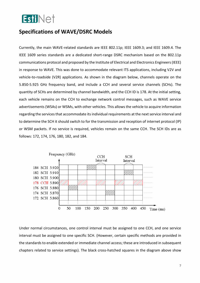
vehicle-to-roadside (V2R) applications. As shown in the diagram below, channels operate on the
5.850-5.925 GHz frequency band, and include a CCH and several service channels (SCHs). The
quantity of SCHs are determined by channel bandwidth, and the CCH ID is 178. At the initial setting,
each vehicle remains on the CCH to exchange network control messages, such as WAVE service
advertisements (WSAs) or WSMs, with other vehicles. This allows the vehicle to acquire information
regarding the services that accommodate its individual requirements at the next service interval and
to determine the SCH it should switch to for the transmission and reception of internet protocol (IP)
or WSM packets. If no service is required, vehicles remain on the same CCH. The SCH IDs are as
follows: 172, 174, 176, 180, 182, and 184.
Under normal circumstances, one control interval must be assigned to one CCH, and one service
interval must be assigned to one specific SCH. (However, certain specific methods are provided in
the standards to enable extended or immediate channel access; these are introduced in subsequent
chapters related to service settings). The black cross-hatched squares in the diagram above show

8
that when a service interval is switched to an SCH, nodes on the SCH can exchange IP and WSM
packets. The times defined by the red-lined squares indicate that after a 50-ms duration [5], the
interval returns to a CCH to receive other service advertisements and information to locate higher
priority services requiring updates in the surrounding reception range. The default duration of the
service intervals and control intervals is set to 50 ms, as recommended by the 1609.4 standard [5].
However, this standard also specifies that values for the two intervals may be adjusted within
different applications. EstiNet provides greater flexibility by allowing users to adjust the duration of
service and control intervals. Further details are introduced in subsequent chapters.
The diagram below shows the integration of IEEE 802.11p/1609 and EstiNet module frameworks or
planes, which are divided into the data and management planes. The data plane supports IP and
non-IP services, such as IPv6 and the WAVE short message protocol (WSMP). When a higher layer
application must transmit or receive data packets, service settings, such as provider, user, WSM,
and CCH services, are sent to standard 1609.3, enabling identification of the correct channel for
receiving or transmitting during the transmission of packets. In EstiNet, users initiate this procedure,
and the graphical user interface (GUI) can be used to implement service settings. Service setting
methods are introduced in later chapters on the four service settings (i.e., provider, user, WSM, and
CCH service settings).
WSMP and WAVE management entity (WME) are implemented using the following source codes in
the EstiNet simulation engine: WSM.cc and wme.cc, respectively. The WME module, located on the
left of the management plane, mainly processes the four service settings (i.e., provider, user, WSM,
and CCH service settings). According to the service setting elements provided by the higher layer, a
WME module communicates with the lower layer to determine the correct SCH that the medium
access control/physical layer (MAC/PHY) should switch to, or notifies the lower layer to send the
WSAs (or the VSAs in the MAC layer). In addition, 802.11p and 1609.4 are implemented by the
mac80211p.cc source codes in EstiNet. All entities related to the physical layer, including codes, are
implemented using phy80211p.cc.

9
10
OBUs and RSUs Supported by ESTINET
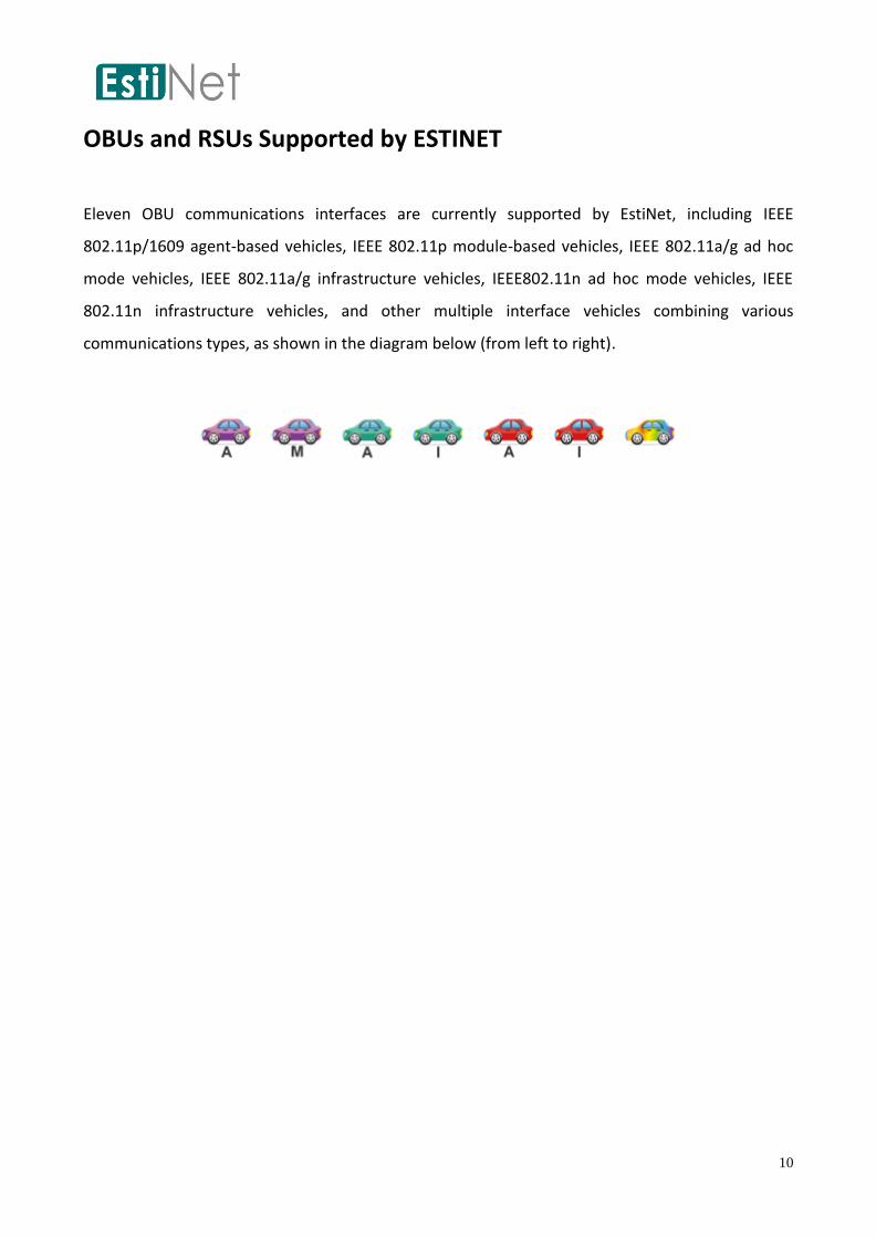
Eleven OBU communications interfaces are currently supported by EstiNet, including IEEE
802.11p/1609 agent-based vehicles, IEEE 802.11p module-based vehicles, IEEE 802.11a/g ad hoc
mode vehicles, IEEE 802.11a/g infrastructure vehicles, IEEE802.11n ad hoc mode vehicles, IEEE
802.11n infrastructure vehicles, and other multiple interface vehicles combining various
communications types, as shown in the diagram below (from left to right).

11
IEEE 802.11p/1609
Introduction to OBUs and RSUs
The description of OBUs in EstiNet focus on introductions to IEEE 802.11p/1609 agent-based
vehicles and IEEE 802.11p/1609 module-based vehicles, as well as design differences and
advantages and disadvantages during use. The introduction to EstiNet IEEE 802.11p/1609 RSUs,
which are illustrated with their protocol stacks in the diagram below, details and introduces IEEE
802.11p/1609 OBUs and RSUs. This is primarily because, if communication behavior is to be
implemented, compliance with 1609.3 service setting rules must be met before switching to the
correct channel for communications. Therefore, in subsequent chapters on the four service settings,
focus is directed at the three IEEE 802.11p/1609 ITS communications devices. In addition, multiple
interface vehicles combining various communications types are compatible with multiple
communications interface installation. Subsequent discussions provide instructions on adjusting
settings in the GUI.
An IEEE 802.11p/1609 RSU is a router, whereas an IEEE 802.11a/g/n access point (AP) is a switch.
Thus, the first has a specific IP address and can be used to transmit and receive Internet packets and
transfer them to IEEE 802.11p/1609 networks. The diagram below shows an RSU connected to a
host, which is then connected to the Internet. The RSU has two communications protocol stacks:
IEEE 802.11p/1609 and IEEE 802.3.

12
In EstiNet, two types of IEEE 802.11p/1609 OBUs are used because different methods exist for
controlling vehicle driving intelligence implementation. As shown in the diagram below, Icon “a”
indicates that the IEEE 802.11p/1609 OBU is an agent-controlled OBU. Vehicle driving intelligence is
controlled by a real-world user-level application. Icon “m” indicates a module-controlled OBU,

13
suggesting that vehicle driving intelligence is embedded or written in the “node” modules of the
EstiNet simulation engine. Both OBUs have specific advantages and disadvantages. An agent-
controlled OBU is essentially a standard real application; the coding is simple and similar to that of
writing a generalized application in Linux. However, one deficiency of this model is that each vehicle
runs a specific agent program, and, consequently, independent procedures must be executed or
activated in the Linux system. If a simulation contains thousands of OBUs, the combined resources
required (e.g., CPU information and main memory) might exceed available system resources,
thereby slowing the simulation speed. By contrast, a module-controlled OBU is controlled by the
node module in the EstiNet simulation engine. This module is a C++ function with multiple members,
and is compiled and associated within the codes of the simulation engine. Controlling such an OBU
does not require the execution of an independent procedure as does an agent-controlled OBU.
Therefore, although one simulation case might contain thousands of OBUs, no additional
procedures are executed and Linux resources are not wasted. Because of the described reasoning,
a simulation using a module-controlled OBU outperforms and is more ideal than one employing an
agent-controlled OBU regarding simulation speed and memory usage. However, the disadvantage
of this method is that developing a module-controlled OBU requires knowledge of writing and
modifying EstiNet modules. Consequently, in consideration of user convenience, the two IEEE
802.11p/1609 OBUs are appropriate for differing applications. EstiNet offers both OBUs to users to
enable them to select the application most suitable to their specific requirements. The protocol
stack content for both IEEE 802.11p/1609 OBUs are shown in the diagram below.
14
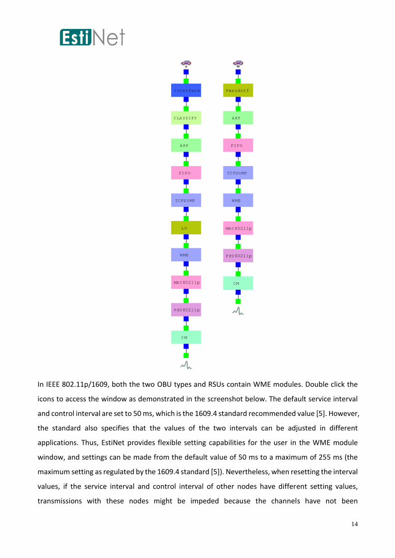
In IEEE 802.11p/1609, both the two OBU types and RSUs contain WME modules. Double click the
icons to access the window as demonstrated in the screenshot below. The default service interval
and control interval are set to 50 ms, which is the 1609.4 standard recommended value [5]. However,
the standard also specifies that the values of the two intervals can be adjusted in different
applications. Thus, EstiNet provides flexible setting capabilities for the user in the WME module
window, and settings can be made from the default value of 50 ms to a maximum of 255 ms (the
maximum setting as regulated by the 1609.4 standard [5]). Nevertheless, when resetting the interval
values, if the service interval and control interval of other nodes have different setting values,
transmissions with these nodes might be impeded because the channels have not been

15
synchronously switched or have already been switched. The advertiser identifier is identical to the
host name, with Node + ID as the default setting.
After the 1609.3 service settings are complete, either an IEEE 802.11p/1609 RSU or OBU can be
selected to serve as the provider or user (only one role can be adopted for one node at a time) based
on differing service control settings. If a higher layer requests provider services from service settings,
the provider role is adopted; the provider role must periodically broadcast WSAs on the CCH control
interval to enable other users (user roles) to determine whether to operate on a SCH based on the
WSA service content. This process assists users in switching to the SCH designated by the provider
service during the service interval. However, if a higher layer requests user services for IEEE
802.11p/1609 nodes regarding service settings, the user role is adopted. When the user role is in
the control interval, it listens to whether the WSA contains service content and an SCH that conforms
to user service. If the result is positive, the user role switches to that particular SCH in the next
service interval for transmission or reception. In this manner, IEEE 802.11p/1609 is different from
other communications protocols. Subsequent chapters provide introductions for designating RSU or
OBU service settings in the GUI, as well as detailed explanations and introductions regarding various
setting fields details.
In the WAVE mode, the addition of a basic service set (BSS) for IEEE 802.11p/1609 does not require
authentication and association procedures because wireless communications between vehicles in a
highly mobile vehicular network environment are extremely fragile (Note: both procedures are
required in IEEE 802.11a/g/n to add an infrastructure BSS for the nodes in the Infrastructure Mode).
Because of these conditions, adding a BSS to a rapidly moving vehicle using traditional methods is
difficult. Consequently, a vehicle can exchange data by quickly receiving WSMs during a control

16
interval. Alternatively, an SCH that can be used to accomplish data exchanges can be quickly
determined through provider and user services, which can periodically receive updated service
advertisement information on the CCH. Subsequent chapters provide explanations regarding the
adjustment of settings for provider and user services for IEEE 802.11p/1609 RSUs and OBUs. The
standard also contains CCH and WSM service settings, which are provided in the EstiNet IEEE
802.11p/1609 module and are introduced later in this manual.
17
Constructing a Road Structure
An ITS network consists of numerous mobile nodes and vehicles that possess communications
network capabilities and travel on road networks. This type of network model raises numerous
possibilities and opportunities for new applications and research. For example, if data are shared
between moving OBUs and RSUs during a routing location situation, vehicles can travel at
appropriate speeds, make safer turns at intersections, and avoid collisions with other vehicles.
Building a road network is the first step in constructing an ITS network simulation. This chapter
presents an explanation of road network construction in EstiNet.
The GUI of EstiNet provides two methods for constructing a road network: The first is accomplished
by accessing shape or open street map (OSM) files, which is explained in the following chapter,
“Accessing Road Map Files.” The second method is achieved by manually using road objects supplied
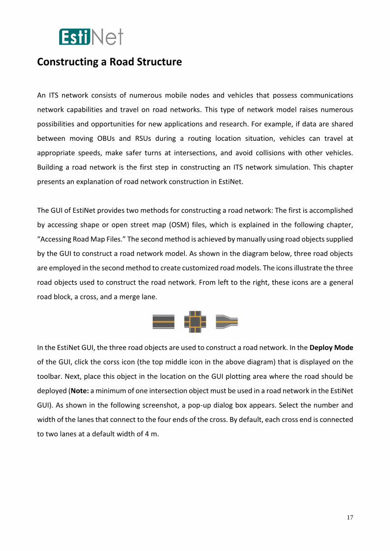
by the GUI to construct a road network model. As shown in the diagram below, three road objects
are employed in the second method to create customized road models. The icons illustrate the three
road objects used to construct the road network. From left to the right, these icons are a general
road block, a cross, and a merge lane.
In the EstiNet GUI, the three road objects are used to construct a road network. In the Deploy Mode
of the GUI, click the corss icon (the top middle icon in the above diagram) that is displayed on the
toolbar. Next, place this object in the location on the GUI plotting area where the road should be
deployed (Note: a minimum of one intersection object must be used in a road network in the EstiNet
GUI). As shown in the following screenshot, a pop-up dialog box appears. Select the number and
width of the lanes that connect to the four ends of the cross. By default, each cross end is connected
to two lanes at a default width of 4 m.

18
To continue, select a general road block object, and place it near one of the four ends of the cross
(Note: ensure that the road block is properly connected to the cross to prevent errors). A dialog box,
as shown above, appears, and the width and number of lanes may be selected (Note: the settings
must be identical to those for the cross to which the lanes are connected). After confirmation, the
road blocks can be connected to gradually form a road network. The last road block must be
connected to the cross to complete the operation. Furthermore, road network deployment can be
increased or decreased to satisfy user requirements. (Note: Any occurrence of red and folded or
bent roads indicates that, in the final plotting of the road in the GUI, folding occurred. To resolve
this problem, move the cursor to adjust the positions of the road blocks or delete the red and folded
sections. Reconnecting the road blocks should prevent this issue.)
Selecting a merge lane object triggers the following dialog box to open. The first option, “Number
of lanes of the ‘From’ road (in both directions),” determines the number of merging lanes. The
second option, “Number of lanes of the ‘To’ road (in both directions),” determines the number of
lanes after merging. The third option determines the width of each lane, and is set to 4 m by default.
Finally, the fourth option determines the orientation of the object (vertical or horizontal). The
default orientation is horizontal.

19
The following screenshot is a road network constructed using the objects described above. Users
can create their own road networks by using the three road network objects.
20
Accessing Road Map Files
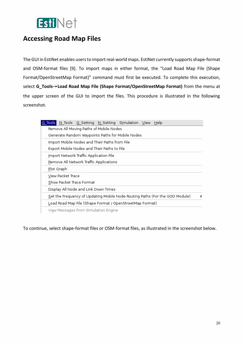
The GUI in EstiNet enables users to import real-world maps. EstiNet currently supports shape-format
and OSM-format files [9]. To import maps in either format, the “Load Road Map File (Shape
Format/OpenStreetMap Format)” command must first be executed. To complete this execution,
select G_Tools→Load Road Map File (Shape Format/OpenStreetMap Format) from the menu at
the upper screen of the GUI to import the files. This procedure is illustrated in the following
screenshot.
To continue, select shape-format files or OSM-format files, as illustrated in the screenshot below.

21
Determine whether the map file is measured in units of longitude and latitude or meters to allow
for the correct interpretation of the file, as shown in the screenshot below. Longitude and latitude
is the default unit selection. Roads are represented as lines on the maps. Before loading or reading
a map, determine the number of road lanes (default setting: two lanes for one road) and the lane
width (default: 4 m), as shown in the dialog box below.
The accessed map file is converted by the GUI program into a structure compatible with EstiNet. The
following screenshot presents a loaded road network.
22
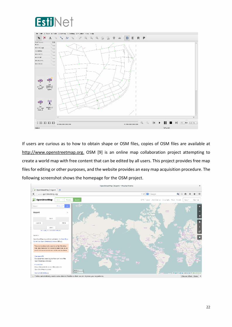
If users are curious as to how to obtain shape or OSM files, copies of OSM files are available at
http://www.openstreetmap.org. OSM [9] is an online map collaboration project attempting to
create a world map with free content that can be edited by all users. This project provides free map
files for editing or other purposes, and the website provides an easy map acquisition procedure. The
following screenshot shows the homepage for the OSM project.

23
To proceed, enter a desired location in the search box on the left, as shown below. Enter a key word,
such as “Taichung,” and the OSM website searches for locations near Taichung City; the map can
then be enlarged for viewing convenience.
Next, select Export, which is the fourth option on the top in the second column from the left. Choose
OpenStreetMap XML Data as the export format. Users may also Manually Select a Different Area
to select a smaller area, as shown below.

24
After determining the range and file format for exportation, click Export, and a Save dialog box
appears. Thus, obtaining an OSM file is extremely straightforward and convenient.

25
Adding and Deploying Vehicles
Once the road network is established, ITS vehicles are deployed. EstiNet provides two methods for
vehicle deployment. The first method is achieved by selecting desired ITS vehicle icons from the
toolbar and dragging them to the road network individually. The vehicle icons can be placed on the
roads as desired. Ensure that the ITS vehicles are correctly placed on the roads; otherwise, the car-
agent programs (vehicle driving intelligence program) or node-module programs (vehicle driving
intelligence portions) cannot detect movement data for the ITS vehicle. This is because a moving
vehicle requires road data to determine and conduct driving actions or behaviors, such as moving
forward, turning, or overtaking other vehicles. Therefore, if an ITS vehicle is not deployed onto a
road, when the simulation begins, it stops off-road and ceases to function. The functions of the car-
agent program are further discussed in later chapters.
The described deployment method demonstrates optimal results with small topology files because
the number of ITS vehicles is small and deployment occurs in a prompt manner. However, the
deployment of a large road network with a vast amount of ITS vehicles is time consuming for users
and requires substantial effort . To address and overcome this issue, EstiNet provides a convenient
tool that automatically and randomly deploys a large amount of ITS vehicles on road networks. This
tool is available in the GUI menu in N_Tools → ITS Network → Deploy cars automatically, as shown
in the screenshot below. (The tool is only available after all road networks are deployed.)

26
Select the tool and a dialog box appears. First, choose an ITS vehicle type to deploy. In the example
in the following screenshot, an IEEE 802.11p-agent-controlled vehicle is selected. Subsequently, set
the average deployment distance between vehicles when in the same lane (i.e., deployment density;
in the figure the default distance is 500 m). The third option determines the number of vehicles of
this type that should be deployed (the maximum number of vehicles that can be deployed in the
simulation). Click OK after the settings are complete. The GUI automatically deploys all vehicles
without placing them outside the road parameters (however, the vehicles can be dragged outside
road parameters manually after deployment). Deployment density limitations may restrict the
number of vehicles to a smaller number than that set in the dialog box.
Automatic deployment of ITS vehicles has two advantages. First, safe deployment is guaranteed.
Vehicles are not deployed outside road parameters (unless users manually drag the vehicles off-
road after deployment); thus, the program functions in a manner that better satisfies user
expectations (otherwise, users may wonder why potentially off-road vehicles exhibit no movement).
The second advantage is that a larger number of vehicles are quickly deployed. Individual vehicle
deployment can be difficult and irritating for users. Fortunately, this interface assists users with
rapid high-quantity vehicle deployment, and saves time regarding trial and error, slowly dragging
vehicles, and determining vehicle position.

27
In the above screenshot of ITS vehicle deployment settings, 10 IEEE 802.11p agent-controlled OBUs
were deployed at distances of 500 m per vehicle. The automatic deployment action can be chosen
several times to deploy additional vehicles.

28
In addition, if you want more precise location of designated car on the road, you can select "Show
Car Location" under N_Setting, then you will gain the location point of designated car.

29
Landmark Addition and Deployment
When ITS vehicles are deployed in a road network, three default directions can be selected when
these vehicles are at an intersection (the road from which the vehicles enter the intersection is
excluded as a possible direction). A random road is selected for the vehicle to travel along using the
Random waypoint model [1], [2], [3]. Thus, during the simulation, all vehicles move randomly in the
road network without a fixed routing rule. However, EstiNet also supports a movement model based
on landmarks [1]. If specific landmarks are designated for an ITS vehicle, the vehicle moves toward
the direction of the designated destination or landmark. In the EstiNet GUI, three landmark types
are supported and can be defined by users. Landmarks can be scenic spots of varying popularity or
different tourist attractions (e.g., red landmarks are restaurants and green landmarks are
recreational venues).
Landmarks can only be deployed after a road network is constructed. Two deployment methods are
provided in EstiNet for landmarks: manual and automatic deployment. Manual landmark
deployment is similar to that for vehicle deployment. Select the landmark icon from the
toolbar in the GUI Deploy Mode, as shown below. A dialog box appears, and users determine the
landmark type for deployment. The default deployment type is blue (Type 1) landmarks. To continue,
place the landmarks on specific roads in the road network individually. Ensure that the landmarks
are placed on the roads; otherwise, the car-agent program (vehicle driving intelligence program) or
the node-module program (vehicle driving intelligence portions) cannot detect the landmark data
or information during simulation (the landmark is a type of road data or information). To move
toward landmarks, vehicles must receive landmark and road data to select a direction for turning at
the intersections.

30
The EstiNet GUI also provides a tool for quick, automatic, and mass landmark deployment. As shown
below, this tool is accessed through N_Tools→ITS Network→Landmark deployment setting in the
GUI menu.
After making a selection, a dialog box appears, as shown in the screenshot below. The design for the
two options shown below is identical to that used for vehicle deployment. The average distance on
the lanes between landmarks can be selected, with a default distance of 500 m. In addition, the
maximum number of deployed landmarks can also be chosen. Subsequently, the user selects the
percentage the three landmark types occupy within the maximum number of landmarks. (Note:
Because certain percentages round the decimal when calculating landmark amount, the actual
number of landmarks may be lower than the maximum number.) After settings are complete and

31
OK is selected, the GUI automatically deploys all landmarks and landmark types without placing
them outside of road parameters.
The sum of the deployed landmark percentages must be 100%. The screenshot below shows the
deployment of 10 landmarks. Tip: In the Edit Property Mode, the Landmark ID and corresponding
type appear when the cursor is placed on the landmark. Double click a landmark to change its type.

32
Designation of Landmark Settings for ITS Vehicles
If users wish to move their vehicles toward a certain type of landmark after the road network, ITS
vehicles, and landmarks are deployed, the landmark type the vehicles are to follow must be set. The
advantage of this method is that these settings can simulate traffic jams and congestion surrounding
popular scenic areas, a situation which has been discussed in numerous studies [1]. After the road
network, ITS vehicles, and landmarks are deployed in EstiNet and when GUI is converted to the Edit
Property Mode, develop configuration settings using N_Tools → ITS Network → Configure cars
landmarks in the menu, as shown in the screenshot below.
After selection, the pop-up dialog box shown in the figure below provides two methods to designate
landmarks for ITS vehicles. One is automated assignment, which randomly designates Landmark IDs
to ITS vehicles based on the three landmark percentages. The other method allows users to
manually designate specific Landmark IDs to specific ITS vehicles. Initially, no ITS vehicle is assigned
to a landmark. Consequently, the initial value for each vehicle is -1, meaning that the next road
direction is randomly selected at an intersection. The following section elucidates the procedures
for automated and manual landmark assignment.
33
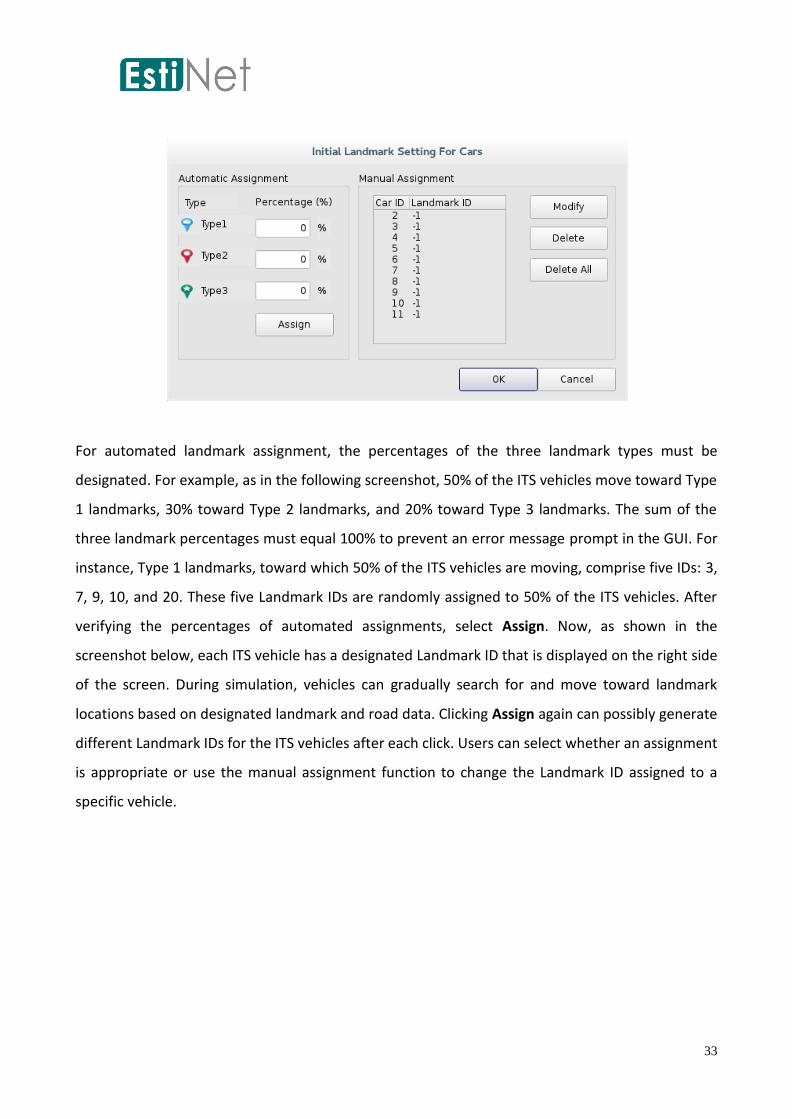
For automated landmark assignment, the percentages of the three landmark types must be
designated. For example, as in the following screenshot, 50% of the ITS vehicles move toward Type
1 landmarks, 30% toward Type 2 landmarks, and 20% toward Type 3 landmarks. The sum of the
three landmark percentages must equal 100% to prevent an error message prompt in the GUI. For
instance, Type 1 landmarks, toward which 50% of the ITS vehicles are moving, comprise five IDs: 3,
7, 9, 10, and 20. These five Landmark IDs are randomly assigned to 50% of the ITS vehicles. After
verifying the percentages of automated assignments, select Assign. Now, as shown in the
screenshot below, each ITS vehicle has a designated Landmark ID that is displayed on the right side
of the screen. During simulation, vehicles can gradually search for and move toward landmark
locations based on designated landmark and road data. Clicking Assign again can possibly generate
different Landmark IDs for the ITS vehicles after each click. Users can select whether an assignment
is appropriate or use the manual assignment function to change the Landmark ID assigned to a
specific vehicle.
34
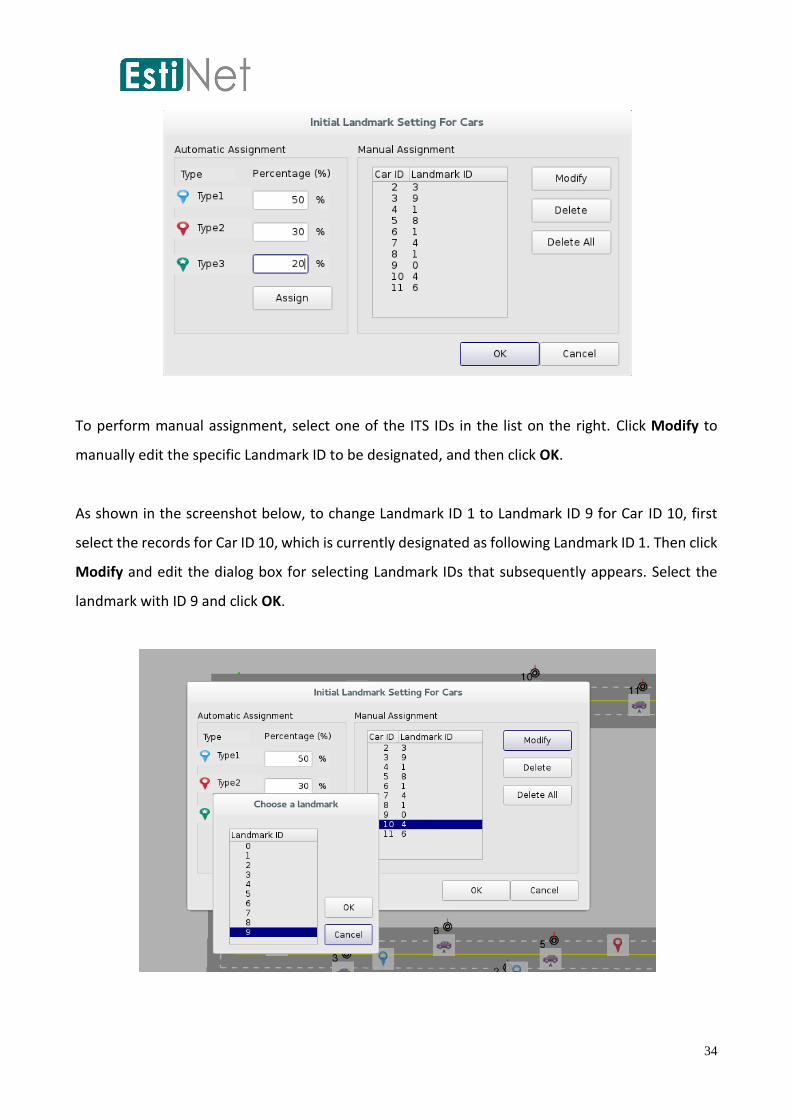
To perform manual assignment, select one of the ITS IDs in the list on the right. Click Modify to
manually edit the specific Landmark ID to be designated, and then click OK.
As shown in the screenshot below, to change Landmark ID 1 to Landmark ID 9 for Car ID 10, first
select the records for Car ID 10, which is currently designated as following Landmark ID 1. Then click
Modify and edit the dialog box for selecting Landmark IDs that subsequently appears. Select the
landmark with ID 9 and click OK.
35
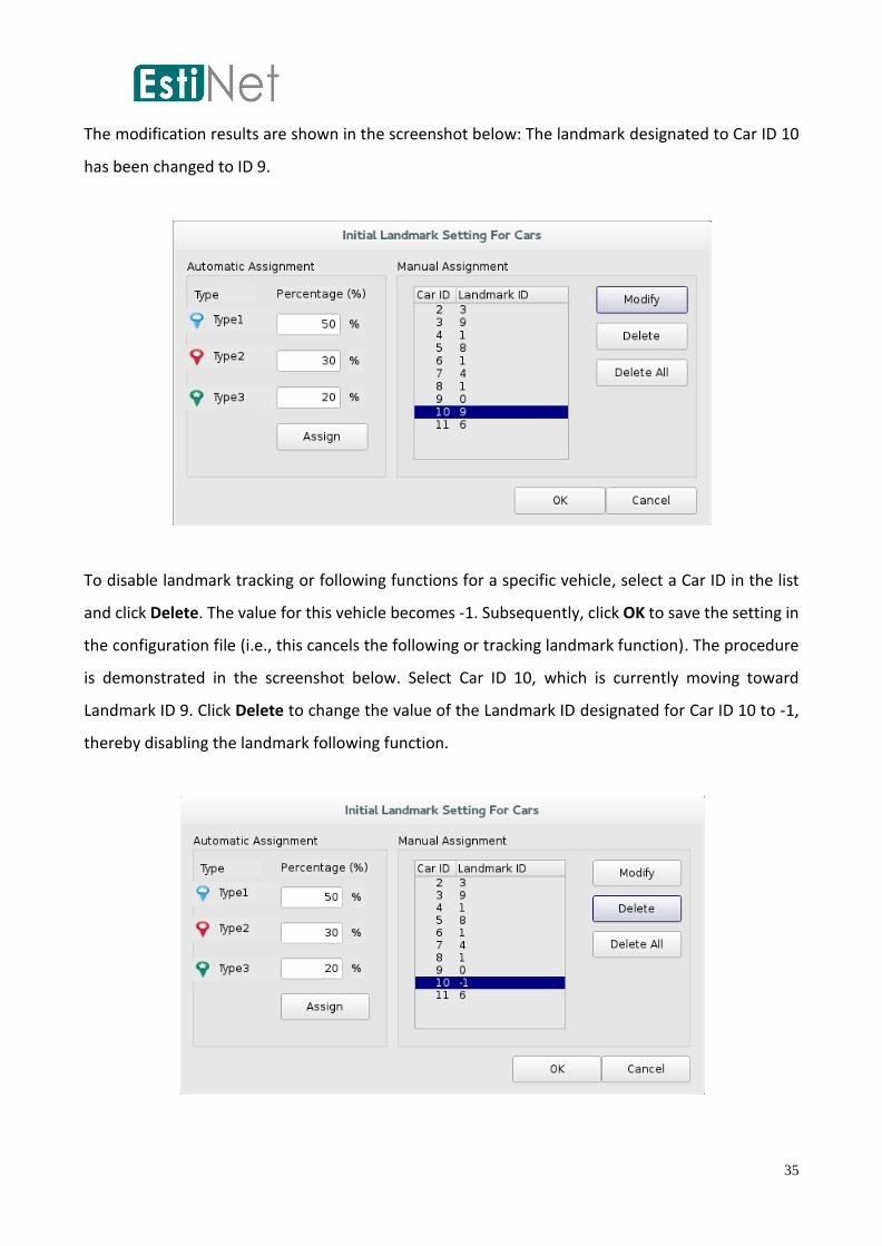
The modification results are shown in the screenshot below: The landmark designated to Car ID 10
has been changed to ID 9.
To disable landmark tracking or following functions for a specific vehicle, select a Car ID in the list
and click Delete. The value for this vehicle becomes -1. Subsequently, click OK to save the setting in
the configuration file (i.e., this cancels the following or tracking landmark function). The procedure
is demonstrated in the screenshot below. Select Car ID 10, which is currently moving toward
Landmark ID 9. Click Delete to change the value of the Landmark ID designated for Car ID 10 to -1,
thereby disabling the landmark following function.

36
To disable landmark tracking and following functions for all vehicles, directly select Delete All and
click OK. As shown in the screenshot below, Landmark IDs designated for all Car IDs have been
changed to -1.
In the simulation, after an ITS vehicle arrives at the landmark destination, it randomly selects a
landmark of the same type as the currently assigned landmark and travels toward this new landmark.
For instance, the landmark assigned in this example is a Type 1 Landmark ID; when the vehicle
arrives at its destination, it randomly selects another Type 1 Landmark ID for its next destination. A
relevant example is presented below: In the figure below, the road network is designed as a grid, in
which 26 IEEE 802.11p module-based ITS vehicles are deployed. In addition, the three types of
landmarks are deployed manually. However, the three landmark types are separately clustered in
different locations: blue landmarks (Type 2) are clustered in the middle left position; red landmarks
(Type 1) are clustered in the middle upper position; and green landmarks (Type 3) are clustered in
the lower right.

37
Landmarks can be assigned to vehicles based on the procedures described above, and users can also
adopt automated assignment. For instance, in the screenshot below, one third of the vehicles are
assigned red landmarks (Type 1), one third are assigned blue landmarks (Type 2), and one third are
assigned green landmarks (Type 3).
Next, disable the traffic light function to ensure that ITS vehicles are not affected by traffic light
interference. When a user selects any intersection, a dialog box appears (see below). The default
setting activates the traffic light function (i.e., Enable Traffic Light Controller is checked), as shown
in the figure below. The traffic light function is implemented using the two options in the bottom of
the diagram: 1) A general signal-agent application written in Linux, and 2) a traffic light program
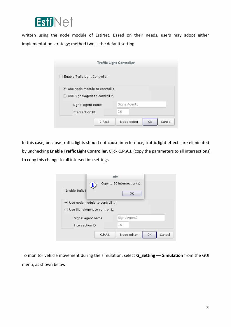
38
written using the node module of EstiNet. Based on their needs, users may adopt either
implementation strategy; method two is the default setting.
In this case, because traffic lights should not cause interference, traffic light effects are eliminated
by unchecking Enable Traffic Light Controller. Click C.P.A.I. (copy the parameters to all intersections)
to copy this change to all intersection settings.
To monitor vehicle movement during the simulation, select G_Setting → Simulation from the GUI
menu, as shown below.

39
In the third tab (i.e., Real Time), Playback packet transmission and node movement after
simulation is selected as the default mode. This option broadcasts all results only after the
simulation. Select Display packet transmission and node movement during simulation
To monitor vehicle movement during the simulation, as shown in the screenshot below.
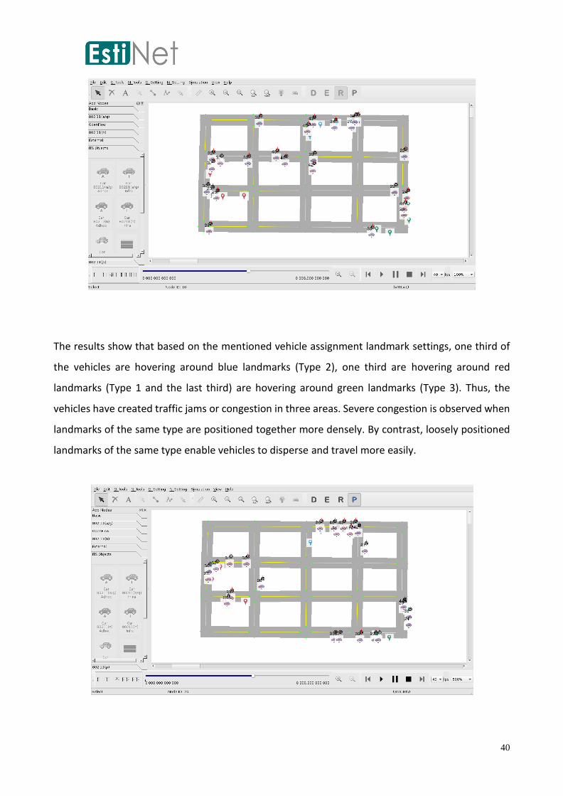
After settings are complete, enter Run Mode to begin the simulation. Vehicle movement is now
monitored during the simulation, as shown in the screenshot below.
40
The results show that based on the mentioned vehicle assignment landmark settings, one third of
the vehicles are hovering around blue landmarks (Type 2), one third are hovering around red
landmarks (Type 1 and the last third) are hovering around green landmarks (Type 3). Thus, the
vehicles have created traffic jams or congestion in three areas. Severe congestion is observed when
landmarks of the same type are positioned together more densely. By contrast, loosely positioned
landmarks of the same type enable vehicles to disperse and travel more easily.

41
If users wish to analyze the path of each vehicle, a file extension node location log (nll) is located in
the .results directory, which is at the same level as the topology file. Using this nll file, users can
access the position, velocity, and acceleration speed of each vehicle for each unit of time.
Alternatively, open N_Setting → 802.11(p) Wireless Network → Show Moving Path through the
GUI to access the same data. However, this method displays numerous vehicle paths and path
information and is not recommend for execution. The procedure is illustrated in the screenshot
below.
The paths of specific vehicles can also be observed. As shown below, select an IEEE 802.11a/g vehicle
and do not assign it a landmark. Double click to enter the settings introduction; at the bottom of the
settings introduction a Show Path option is presented. This check box is unchecked by default. Check
this box to display only the path of the selected vehicle in the Playback Mode after the simulation
is complete.

42
43
Settings for and Definition of Vehicle Driving Behavior
Car Profile
After an ITS vehicular environment is deployed, the user may wish to control the driving behavior of
each ITS vehicle. To achieve this objective, EstiNet implements a car profile method, which enables
each vehicle to possess a unique and automatic driving behavior. These driving behaviors are
recorded in the car profiles. Five car profile templates are currently supported by EstiNet. The setting
files are accessed by either an agent or a node-module application dependent on the vehicular type
(agent based or module based). Detailed setting procedures are described in the following section.
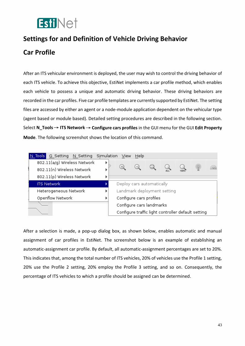
Select N_Tools → ITS Network → Configure cars profiles in the GUI menu for the GUI Edit Property
Mode. The following screenshot shows the location of this command.
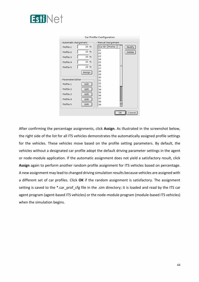
After a selection is made, a pop-up dialog box, as shown below, enables automatic and manual
assignment of car profiles in EstiNet. The screenshot below is an example of establishing an
automatic-assignment car profile. By default, all automatic-assignment percentages are set to 20%.
This indicates that, among the total number of ITS vehicles, 20% of vehicles use the Profile 1 setting,
20% use the Profile 2 setting, 20% employ the Profile 3 setting, and so on. Consequently, the
percentage of ITS vehicles to which a profile should be assigned can be determined.
44
After confirming the percentage assignments, click Assign. As illustrated in the screenshot below,
the right side of the list for all ITS vehicles demonstrates the automatically assigned profile settings
for the vehicles. These vehicles move based on the profile setting parameters. By default, the
vehicles without a designated car profile adopt the default driving parameter settings in the agent
or node-module application. If the automatic assignment does not yield a satisfactory result, click
Assign again to perform another random profile assignment for ITS vehicles based on percentage.
A new assignment may lead to changed driving simulation results because vehicles are assigned with
a different set of car profiles. Click OK if the random assignment is satisfactory. The assignment
setting is saved to the *.car_prof_cfg file in the .sim directory; it is loaded and read by the ITS car
agent program (agent-based ITS vehicles) or the node-module program (module-based ITS vehicles)
when the simulation begins.

45
To manually assign profiles, select any record in the list on the right. For example, select the record
for Car ID 21, as shown above. Click Modify and a dialog box appears, as shown below. The Default
Mode will select the currently designated profile, which can be manually changed at the discretion
of the user. After verification, click OK to complete the modification. This function is useful when
users would like specific car profiles assigned to specific vehicles during simulation.
The screenshot below shows the dialog box that appears to enable users to change the car profile
for a selected ITS vehicle.

46
The screenshot below shows the modified result, in which Profile 5 is now assigned to Car ID 21. To
disable profile settings for ITS vehicles, select a record and click Delete to clear the settings. For
example, select Car ID 21 and click Delete, as shown below.
After deletion, the setting field for the profile settings of Car ID 21 is cleared, as shown below.
47
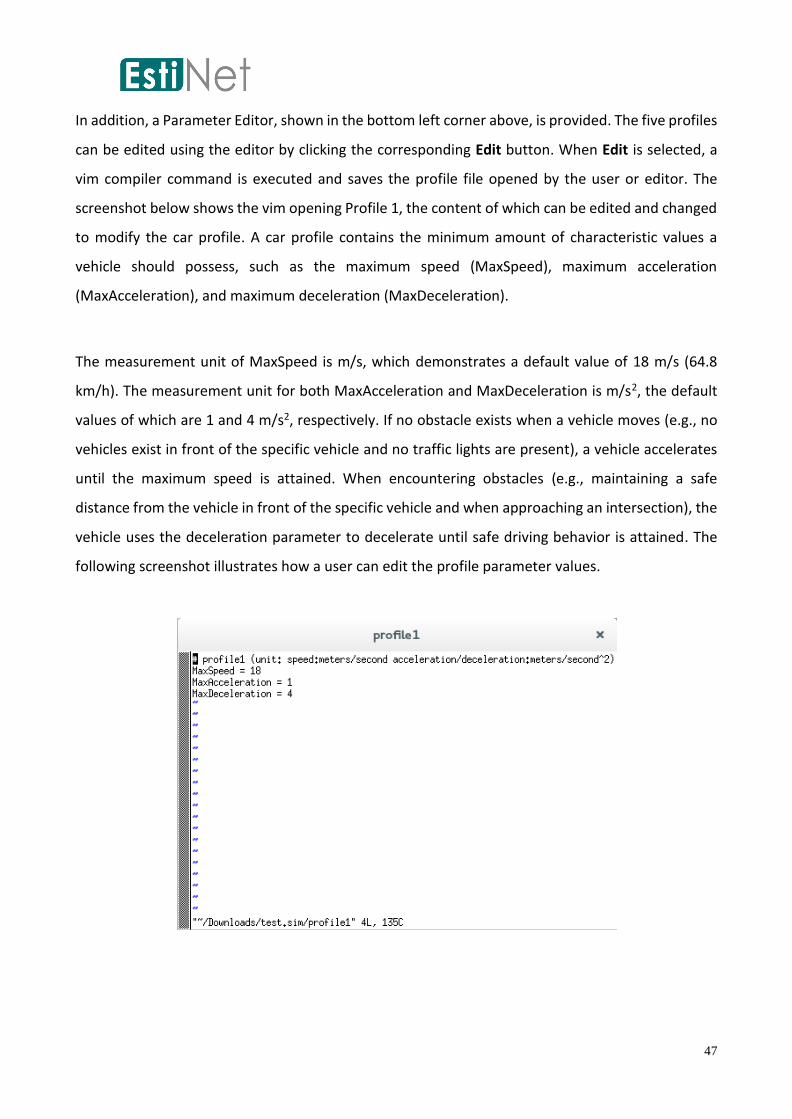
In addition, a Parameter Editor, shown in the bottom left corner above, is provided. The five profiles
can be edited using the editor by clicking the corresponding Edit button. When Edit is selected, a
vim compiler command is executed and saves the profile file opened by the user or editor. The
screenshot below shows the vim opening Profile 1, the content of which can be edited and changed
to modify the car profile. A car profile contains the minimum amount of characteristic values a
vehicle should possess, such as the maximum speed (MaxSpeed), maximum acceleration
(MaxAcceleration), and maximum deceleration (MaxDeceleration).
The measurement unit of MaxSpeed is m/s, which demonstrates a default value of 18 m/s (64.8
km/h). The measurement unit for both MaxAcceleration and MaxDeceleration is m/s2, the default
values of which are 1 and 4 m/s2, respectively. If no obstacle exists when a vehicle moves (e.g., no
vehicles exist in front of the specific vehicle and no traffic lights are present), a vehicle accelerates
until the maximum speed is attained. When encountering obstacles (e.g., maintaining a safe
distance from the vehicle in front of the specific vehicle and when approaching an intersection), the
vehicle uses the deceleration parameter to decelerate until safe driving behavior is attained. The
following screenshot illustrates how a user can edit the profile parameter values.

48
Car Agent and Signal Agent Programs
After an intersection is deployed, if it is selected as being executed by the Signal Agent, a
SignalAgent1 application is automatically activated when the simulation begins. The Signal Agent
controls changes in the traffic lights (as shown below). Alternatively, users can control or implement
the traffic lights by using the node module, which is the default setting. The current Signal Agent
name cannot be modified. Furthermore, by editing the settings for the SignalAgent1 program, users
can determine traffic-light behavior. The source code for SignalAgent1 is located in the source code
path directory in the EstiNet installation package:
estinetse/appliation/its/VehicularNetwork/SignalAgent1.cc.
Similarly, at the beginning of the ITS vehicle simulation, a CarAgent application is automatically
executed. The CarAgent application controls vehicle driving behavior. Moreover, specific car profile
input parameters can be designated to control driving behavior.
This type of user-level and real-world application is written using C/C++. To execute this command
string during the simulation, it must be entered into Application for the ITS vehicle in the GUI (refer
to the screenshot below).
However, automatically deploying hundreds of ITS vehicles in the road network may be required
during this process. If this situation occurs, users are required to open a dialog box for each ITS
vehicle and enter the CarAgent command string manually, which is inconvenient and time-

49
consuming. Therefore, a default “CarAgent -s” command string is input into Application for each
deployed agent-based ITS vehicle in the GUI program. This command executes the CarAgent
program by default during the simulation. If users prefer a CarAgent program with different driving
behavior, the default CarAgent can be replaced by a customized program. Users can locate and
modify the CarAgent source code in the EstiNet installation package based on their requirements.
The source code is located in the source code path directory in the EstiNet installation package:
estinetse/appliation/its/VehicularNetwork/CarAgent.cc.
The “-s” parameter in “CarAgent -s” represents the switch lane function, which is turned on by
default. This function is only available and functional for multi-lane roads. If vehicles are detected in
the front of a specific car and the road provides more than one lane, users can determine whether
the vehicle should switch to another lane (Note: the switch lane function is not activated when only
one lane exists). Other parameters also exist. For example, “-its” indicates that a CarAgent program
can transmit its own packets, which may include robust road information that can be broadcast to
other CarAgents; “-p” designates the port transmitting the packets (4000 by default); and “- v”
determines the driving velocity or speed of the CarAgent.

50
The CarAgent program is a preset tool in the EstiNet installation package, and serves as the
implementation of a conceptual reference, demonstrating that this type of Agent program can use
logical driving behavior and intelligence to drive ITS vehicles.
Similar parameter settings are available for module-based ITS vehicles. Car IDs and the switch lane
function option (which is selected as a default setting) appear after a module-based vehicle is
selected.
The preceding chapters provided instructions for deploying the infrastructure of the ITS road
networks and introduced settings for vehicular driving behavior. The subsequent chapters illustrate
the service settings for IEEE 802.11p/1609.3 from a communications perspective. These chapters
discuss 1609.3 provider, user, WSM, and CCH service settings, as well as introduce and provide
setting examples for WSM and WSM_Forwarding, which are two user-level applications provided
by EstiNet.

51
IEEE 802.11P/1609 Communications Settings
IEEE 802.119/1609 consists of the data plane and the management plane. The data plane supports
IP services and the WSMP. In addition, regarding the selection of transport layer protocols that are
higher than the IP layer, UDP is required and TCP is optional. These two communications protocols
are supported by EstiNet traffic tools. General IP data are transmitted through the IP layer. However,
real-time data are transmitted by the WSMP protocol because these data should be sent and
received promptly without experiencing general packaging in the TCP/IP.
When applications in a higher layer are required to send or receive data packets, service settings
must be executed to verify whether a provider or user role is to be adopted. A provider must send
WSAs during the control interval to all ITS vehicles, which then compare the WSA service content
with their own user service demands. Consequently, when the next service interval begins, the
applications are switched to the same SCH for application. If the data packets sent and received by
applications in the higher layer require the use of the WSMP protocol, the determination of
provider/user service is not required because transmission occurs through either the CCH or the
SCH. However, the receiver must still set WSM service and determine which WSM packets for the
provider service identifier (PSID) will be received.
EstiNet supports the following 1609.3 service requests: provider, user, CCH, and WSM. Provider
service requests indicate that the higher level must employ WSA to broadcast the services provided
by the provider. A WSA packet contains a maximum of 32 services, which are distinguished by the
PSID, and provides the service-accessed SCH. In addition to the mentioned functions, provider
service requests are used to broadcast configuration information, such as enhanced distributed
channel access (EDCA) parameters or system information (e.g., country or geographical information).
User service requests are services requested by the higher layer. If any service in the WSAs that are
received by the WAVE devices fulfills certain conditions, channels can then be determined according
to the information provided by the WSAs and the service can be used. WSM service requests
indicate that the higher layer hopes to receive WSM information that fulfills a certain PSID. When a
WAVE device receives a WSM, it compares whether the PSID of the WSM corresponds to an
application in the higher layer to determine reception of the packet. CCH service requests are
52
submitted by the higher layer, which intends to access the CCH continuously during a certain interval,
such as WSM activities or WSA reception.
Thus, the following descriptions show 1) how using the EstiNet GUI to adjust provider service
settings can enable a certain node to become the provider and send WSAs; 2) how other nodes can
become the user through the adjustment of user-service settings; 3) how to adjust CCH service
settings; and 4) how to adjust WSM service settings. Users can easily and flexibly adjust these four
settings through the EstiNet GUI, and the GUI provides parameter settings for the four services.
Regarding a detailed description of service settings, the following chapters introduce procedures for
GUI settings and the parameters in the four service settings. Furthermore, EstiNet provides two
applications (WSMs and WSM_Forwarding) for WSM packet transmission, which are presented in
later chapters.
In addition, to increase the flexibility of multi-channel operation, IEEE 1609.4 provides four channel
access mechanisms for users: 1) continuous access, 2) alternating access, 3) immediate access, and
4) extended access, as shown in the diagram below. These four channel access methods can be
adjusted and set from higher to lower levels using the four GUI service setting interfaces. The
continuous access mechanism monitors the CCH continuously. If no service is requested for
execution, the device remains on the CCH by default. Moreover, 1609.3 CCH services can be adopted
directly to perform applications that must remain on the CCH for a certain interval. Alternating
access uses the SCH during the service interval and the CCH during the control interval. This access
alternates between the SCH and CCH based on the cycle of the sync interval, and if the 1609.3 service
is not designated as another channel access method, the alternating access mechanism is adopted.
Users may switch immediately to the desired SCH through the immediate access mechanism, and
with the extended access mechanism, users can extend the period of use for a particular SCH to
increase transmission performance. The procedure is illustrated in the diagram below.
In the diagram below, the initial channel interval is known as the guard interval, which includes the
time required for alternation or switching and synchronization. A sync interval comprises a control
interval, a service interval, and two guard intervals to exchange all types of data (e.g., management,
control, and information). By default, both the control interval and service interval are 50 ms, the
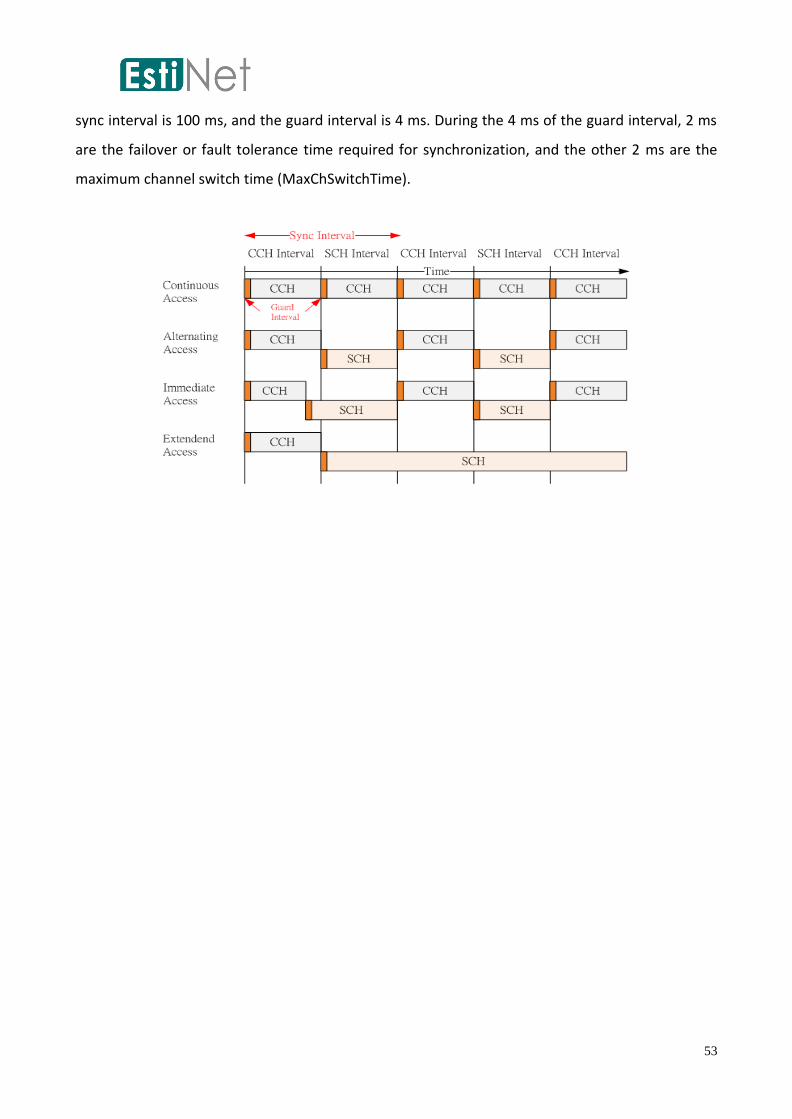
53
sync interval is 100 ms, and the guard interval is 4 ms. During the 4 ms of the guard interval, 2 ms
are the failover or fault tolerance time required for synchronization, and the other 2 ms are the
maximum channel switch time (MaxChSwitchTime).

54
Provider/User Service Settings
To familiarize users with provider/user service settings, the following sections offer an example that
discusses the communication between two ITS OBU vehicles or the communication between one
RSU and one ITS OBU vehicle using a simple topography format. In the GUI topology below, Nodes
2, 3, and 4 are set so that they are covered by the communications range (the subnet should be set
first). Node 3 attempts to communicate with Node 4, and Node 2 is the provider that broadcasts
WSA to notify Nodes 3 and 4 of the available SCH for access. (Users may also set Node 3 as the
provider and Node 4 as the user.)
Note: If an RSU exists in the above figure, the GUI must include Nodes 2, 3, and 4 in the same subnet.
To achieve this result, first click the select wireless to form a subnet icon (see figure below) in the
GUI toolbar, as shown in the screenshot below.
Next, click Nodes 2, 3, and 4 consecutively using the left button on the mouse. Right click to finish
the process, and a child window for subnet formation appears, as shown in the screenshot below.

55
The subnet can also be managed through N_Tools → 802.11(p) Wireless Network → Manage
802.11(p) Subnets in the GUI menu, as illustrated in the screenshot below.
After selecting the above command, the following dialog box appears, in which Nodes 2, 3, and 4
belong to Subnet ID 1. On the right of the dialog box Delete Subnet, which deletes the information
of any selected subnet, is shown. After the subnet is deleted, users can select a new subnet by
following the same procedure described above.

56
After the subnet is established, Nodes 2, 3, and 4 can communicate with each other and their
distance is controlled by the communications range. To adjust provider service settings, first select
Node 2 of the IEEE 802.11p/1609 RSU. In the Edit Property Mode of the GUI, double click Node 2,
and a dialog box, as shown in the screenshot, appears. Select Provider/User Service Setting. The
upper section of the tab displays the entries for each provider service. To the right of the tab are
buttons, including Add, Edit, and Delete, that create, modify, and remove the information of a new
provider service, respectively. DelAll and CpyAll can also be used to adjust or give similar service
settings to numerous OBUs and RSUs. For example, use CypAll to copy a PSID 2 provider service
setting to multiple other RSUs or OBUs and use DelAll to simultaneously delete settings.
After selecting Node 2, click Add next to the upper Provider Service Information Table to add a new
setting for the provider service. As shown in the screenshot below, a settings window with nearly
20 settings (including optional settings) appears.
Time (s): This column refers to the point when specific service information is processed by the
provider service during simulation.
Action: This column refers to the action to be executed by the provider when the simulation time
reaches a designated point. The full use edition of 1609.3 defines the three provider service actions
as Add, Delete, and Modify, which are all supported by EstiNet. The Add function creates a new

57
provider service in the 1609.3 management information base (MIB) and prepares to send the WSA.
If the node has not been established as the provider, it sets itself as the provider at this time and
creates new WSA content in preparation for transmission. If the node is originally a provider, it
modifies the MIB (the management information table in the WME module) and the previous WSA
content and attempts to add new provider service information. Unless the WSA contains more than
32 provider services, a new WSA packet is created for transmission. A maximum of 128 provider
services (equivalent to 4 WSA packets) can be sent or transmitted. The Delete function or action
deletes a certain entry of the provider service information stored in the MIB and modifies or deletes
WSA content. Typically, Delete is executed after a provider service is added. The Modify function or
action changes provider service content stored in the MIB and edits WSA content. This function is
also frequently executed after the addition of provider services.
PSID: This column is used to distinguish and identify the service ID. The current length of a PSID has
been changed from the original fixed length of 4 octets to a variable value, which can be greater
than or equal to 5 octets, but which is often retained at a lower level. At present, the EstiNet PSIDs
can support a range from 0 to 999999999.

58
Service Priority: This column defines the priority level of a certain provider service. A higher value
indicates that the service possesses a higher priority to access an SCH. No influence or effects occur
when two PSIDs with different priority levels hope to access the same SCH; however, if two PSID
provider services with different priority levels request two different SCHs, the SCH requested by the
59
provider service with higher priority is selected as the primary SCH. The range for service priority
constitutes integer values ranging from 0 to 63 (0 being the lowest and 63 the highest).
Channel Access: Two methods are available, alternating (default) and continuous. The default
alternating channel access mechanism remains on the CCH during the control interval and switches
to the SCH during the service interval. After transmitting the WSA in the first CCH, the continuous
channel access mechanism remains on the SCH after the next service interval rather than switching
back to the CCH. Transmission continues and is increased until the end of all services. Unless
amendments are made to the provider service, the mechanism does not return to the CCH to send
new WSAs.
Service Channel ID: This column defines the SCH ID used by the service. The available and
permissible SCH IDs include 172, 174, 176, 180, 182, and 184.
Provider Service Context (PSC; WSA): This is an optional setting (i.e., a specific setting is not
required). A provider service can be described by the PSC using ASCII strings. The maximum number
of bytes is 31.
The WSA Repeat Rate (times/5 s): The number of WSAs sent during every 5 s interval. This default
parameter is set to 50 WSAs/5 s. Therefore, one WSA message is sent in each control interval. This
setting provides a range from 0 to 255. The minimum value 0 sends only one WSA message during
the entire simulation. With a maximum value of 255, the setting is ignored and only one WSA is sent
if the service has designated a MAC address.
IP Service: This setting determines whether the IP service is supported. The default is supported.
Service Port: This optional setting is only available after IP service is provided. Port IDs can be
assigned using integers ranging from 1 to 65535 (0 if service is not limited by the setting of a certain
Port ID).
Transmit Power Level (Service; dBm): An optional setting (i.e., a specific setting is not required) that,
if activated, determines the power transmitted by the provider services in SCHs.
Transmit Power Used (WSA; dBm): An optional setting (i.e., a specific setting is not required) that,
if activated, determines the power of WSA transmission.
Data Rate (Service; Mbps): An optional setting (i.e., a specific setting is not required) that, if
activated, determines the transmitted data rate of provider services on SCHs. Data rate settings
permissible in EstiNet include 3, 4.5, 6, 9, 12, 18, 24, and 27 Mbps.
60
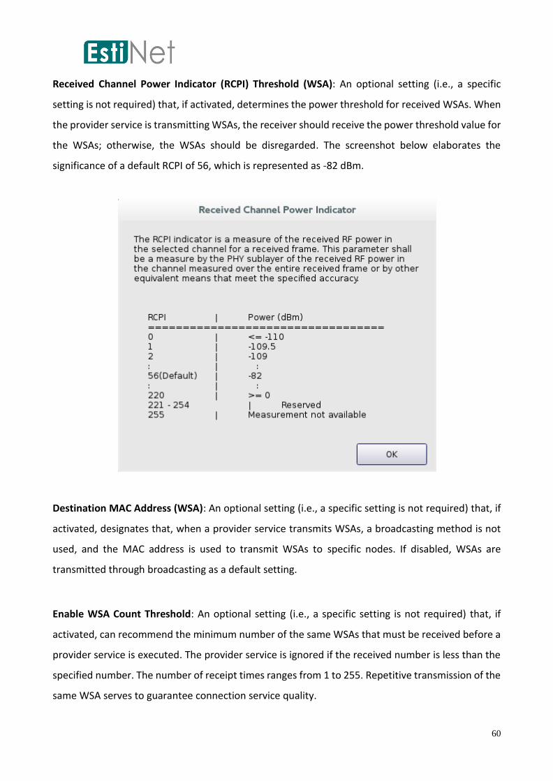
Received Channel Power Indicator (RCPI) Threshold (WSA): An optional setting (i.e., a specific
setting is not required) that, if activated, determines the power threshold for received WSAs. When
the provider service is transmitting WSAs, the receiver should receive the power threshold value for
the WSAs; otherwise, the WSAs should be disregarded. The screenshot below elaborates the
significance of a default RCPI of 56, which is represented as -82 dBm.
Destination MAC Address (WSA): An optional setting (i.e., a specific setting is not required) that, if
activated, designates that, when a provider service transmits WSAs, a broadcasting method is not
used, and the MAC address is used to transmit WSAs to specific nodes. If disabled, WSAs are
transmitted through broadcasting as a default setting.
Enable WSA Count Threshold: An optional setting (i.e., a specific setting is not required) that, if
activated, can recommend the minimum number of the same WSAs that must be received before a
provider service is executed. The provider service is ignored if the received number is less than the
specified number. The number of receipt times ranges from 1 to 255. Repetitive transmission of the
same WSA serves to guarantee connection service quality.
61
WSA Count Interval (number of 100 ms periods): An optional setting (i.e., a specific setting is not
required) that, if activated, is used in coordinate with Enable WSA Count Threshold and can
determine the time interval for WSA reception using a unit of 100 ms. The setting value ranges from
1 to 255, and the default value is 1 s (i.e., the default setting value is 10). If the Enable WSA Count
Threshold setting value is activated and this setting is disabled, the WSA must be received within a
minimum of 1 s by default. This option further guarantees connection service quality.
Enable Advertiser ID (WSA): An optional setting (i.e., a specific setting is not required) that, if
activated, inserts an advertiser identifier (32 bytes is the maximum length) into WSA packets. When
this option is enabled in EstiNet, node IDs are inserted into packets. The main purpose of these IDs
is for device identification, which is different from service identification using PSC.
Enable EDCA (Service): An optional setting (i.e., a specific setting is not required) that, if activated,
determines the quality of service (QoS) settings in the SCH for the provider service transmission.
When the EDCA Setting option is activated, this action is enabled (and can edit the QoS setting value
in the MAC). If this setting is enabled but the parameters in the EDCA Setting dialog box are not
modified, default QoS settings in the MAC module are primarily adopted.
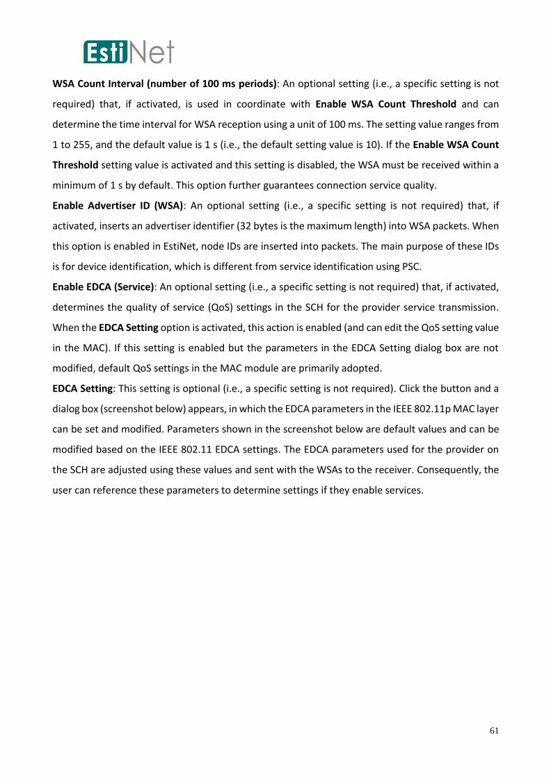
EDCA Setting: This setting is optional (i.e., a specific setting is not required). Click the button and a
dialog box (screenshot below) appears, in which the EDCA parameters in the IEEE 802.11p MAC layer
can be set and modified. Parameters shown in the screenshot below are default values and can be
modified based on the IEEE 802.11 EDCA settings. The EDCA parameters used for the provider on
the SCH are adjusted using these values and sent with the WSAs to the receiver. Consequently, the
user can reference these parameters to determine settings if they enable services.

62
If users are unsure as to how to modify these 20 settings, they should choose the default values and
modify only the critical parameters, such as PSID and SCH ID. As shown in the screenshot below, in
the settings for the provider service added in Node 2, only PSID (1) and SCH ID (172) are modified;
other parameters remain at their default settings.
63
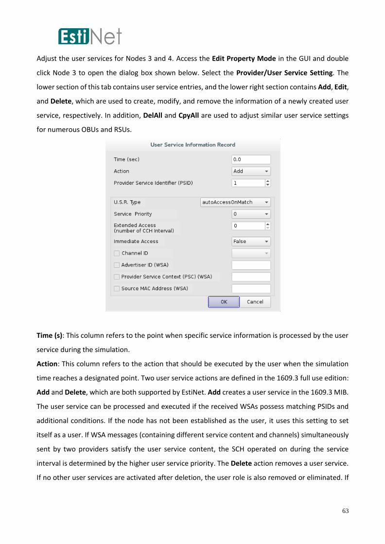
Adjust the user services for Nodes 3 and 4. Access the Edit Property Mode in the GUI and double
click Node 3 to open the dialog box shown below. Select the Provider/User Service Setting. The
lower section of this tab contains user service entries, and the lower right section contains Add, Edit,
and Delete, which are used to create, modify, and remove the information of a newly created user
service, respectively. In addition, DelAll and CpyAll are used to adjust similar user service settings
for numerous OBUs and RSUs.
Time (s): This column refers to the point when specific service information is processed by the user
service during the simulation.
Action: This column refers to the action that should be executed by the user when the simulation
time reaches a designated point. Two user service actions are defined in the 1609.3 full use edition:
Add and Delete, which are both supported by EstiNet. Add creates a user service in the 1609.3 MIB.
The user service can be processed and executed if the received WSAs possess matching PSIDs and
additional conditions. If the node has not been established as the user, it uses this setting to set
itself as a user. If WSA messages (containing different service content and channels) simultaneously
sent by two providers satisfy the user service content, the SCH operated on during the service
interval is determined by the higher user service priority. The Delete action removes a user service.
If no other user services are activated after deletion, the user role is also removed or eliminated. If
64
other user services that were activated by the WSA remain in progress, the user role is retained, or
a lower priority user service is activated.
PSID: This column is used to distinguish and identify the service ID. Currently, the length of the PSID
has been changed from the original fixed length of 4 octets to a variable value, which can be greater
than or equal to 5 octets but is still retained at a lower level. At present, the EstiNet PSID supports
a range from 0 to 999999999.
User Service Request (U. S. R. ) Type: Currently EstiNet supports two types of user service requests:
auto-access on service match and auto-access unconditionally. The first is the default value: it
assumes that user comparison is executed after the WSA is received to determine the execution of
user services. The second request unconditionally and automatically activates user services and
switches SCHs; it does not require provider WSAs for communication and is compatible with V2V
applications.
Service Priority: This column defines the priority level of a certain user service. A higher value
indicates that the service has a higher priority to access SCHs. For example, no effects occur when
two user services with different priority levels that are activated after comparing WSAs attempt to
access the same SCH; however, if two services with different priority levels request two different
SCHs, the SCH requested by the user service with higher priority is selected. The service priority
range constitutes integer values ranging from 0 to 63 (0 being the lowest and 63 the highest).
Extended Access (Number of Control Intervals): The default for this option is 0. When the value is
0, this indicates that a general alternating channel access mechanism is adopted, in which channel
access remains on the SCH during the service interval and switches to the CCH during the control
interval. The setting values range from 1 to 255; these values indicate the number of times that
services may remain on the SCH without switching to the CCH during the control interval after
entering the SCH. Value 255 provides unlimited access to the SCHs. Entering a value between 1 and
255 indicates that continuous SCH access is necessary to increase the transmission rates until the
end of services. Unless the services are modified or other services intervene (e.g., CCH services or
user services with higher priority levels), the set extended service interval continues until
completion.
Immediate Access: This option enables immediate access. The default value is False. If the setting is
switched to True, SCHs are accessed immediately with no requirement to wait until the subsequent
service interval.

65
Channel ID: This setting is optional (i.e., a specific setting is not required). If enabled, this setting
requires WSA comparison services to include PSID and future SCH ID comparisons. User services are
activated only if the comparison results are successful. The permissible SCH IDs include 172, 174,
176, 180, 182, and 184.
PSC (WSA): This setting is optional (i.e., a specific setting is not required). If enabled, this option
requests WSA comparison services to include PSID comparisons, as well as comparisons to
determine whether PSC content matches the requirements of the user services. User services are
only activated if the comparison results are positive or successful.
Source MAC Address (WSA): This setting is optional (i.e., a specific setting is not required). If enabled,
this option requests WSA comparison services to include PSID comparisons, as well as comparisons
of the WSA transmitter MAC address. User services are only activated if the comparison results are
positive or complementary.
The PSID of Node 3 is set at 1, which is the same setting for Node 2 of the provider. Other PSIDs are
set based on WSA content comparisons. Consequently, after the user service PSID is set at one, the
process is complete. The results of adding a user service are displayed in the screenshot below. In
addition, the user service settings of Node 3 can be copied to the other OBU, which is Node 4. In
Node 3, select Provider/User Service Setting; when selected, a user service portion is viewable in
the bottom section of the menu. Click CpyAll, located on the right of the user service section, check
All Other OBU Nodes, and click OK. After this procedure is completed, Node 4 has the same user
service settings as Node 3.

66
To continue, Node 3 is designated as the transmitter that sends packets to Node 4, as shown in the
screenshot below. In Application for Node 3, enter the traffic generation tool transmitter command.
Designate the Port ID as 2000, and assign IP address 1.0.2.3 to Node 4.
67
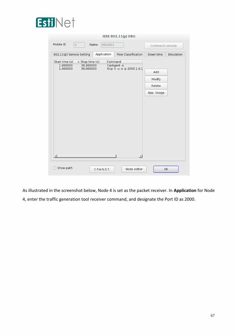
As illustrated in the screenshot below, Node 4 is set as the packet receiver. In Application for Node
4, enter the traffic generation tool receiver command, and designate the Port ID as 2000.

68
After all settings are adjusted, switch to the Run Mode to start the simulation. The screenshot below
shows the simulation result. After Node 2 (functioning as the provider) sends the WSA containing
PSID 1 service, Nodes 3 and 4 receive the WSA and activate their user services if PSID 1 matches
their requirements or is of interest. In addition, Nodes 3 and 4 both switch to SCH 172 during the
service interval. Packet transmission from Node 3 to Node 4 is successful because both nodes are
operating on SCH 172. On the scroll bar representing time at the bottom of the screen, the green
segments indicate data transmission, and the intervening intervals indicate the time frames that
node operation reverted to the CCH during the control interval. No data were transmitted at this
time, and transmission and reception were suspended until the next service interval.

69

70
CCH Service Settings
CCH service refers to continuous access to the CCH requested by a higher layer during a certain
period. Using the topology discussed in the previous sections, Node 3 sends data to Node 4 on SCH
172 after their user services are set and receive WSA comparisons. When the simulation reaches the
fifth second, Node 3 must revert to the CCH for 5 s because, for certain reasons (e.g., receiving
emergency WSMs), it must return to the control interval for a lengthy period to monitor control
messages. This section first introduces how to adjust the CCH service settings for Node 3.
Access Edit Property Mode in the GUI and double click Node 3. A dialog box (screenshot below)
appears. Select CCH Service Setting; the left side displays the CCH service entries and the right side
displays Add, Edit, and Delete. These three buttons are used to create, modify, and remove new
CCH service data or information. The DelAll and CpyAll buttons are used to adjust and provide
similar CCH service settings for numerous OBUs and RSUs. Descriptions of fields and relevant values
in the new settings dialog box that appears after Add is selected are as follows:
71
Time (s): This field indicates the point when specific CCH service information is processed in the
simulation.
Action: This field indicates the required action that the provider or user must or should initiate when
the simulation time reaches a designated point. The 1609.3 full use edition defines two CCH service
actions: Add and Delete; both are supported by EstiNet. Add creates a CCH service in the 1609.3
MIB. The service is executed or activated depending on the Channel Interval and Service Priority
options shown in the next screenshot. An activated service remains on the CCH until the CCH service
is terminated or is subject to intervention (e.g., a delete action is executed or provider/user services
that have higher priority are received after CCH service execution).
Channel Interval: This field shows three values: CCH, SCH, and BOTH. Select the CCH interval to
allow services to operate on the CCH during the control interval. This option is typically used to
override or prevent the continuous access requested by provider services and the immediate and
extended access requested by user services. Select the SCH interval to allow services to operate on
the CCH during the service interval, and select BOTH to allow services to operate on the CCH during
either the service or the control interval.
Service Priority: This option defines the priority level of a given CCH service. A higher value indicates
that the CCH service has a higher priority to access SCHs. Service priority is an integer ranging from
0 to 63 (0 is the lowest and 63 the highest). When a CCH service is activated, its priority is compared
with the provider/user service that is currently activated. If the CCH service has a priority that is
higher than the provider/user service, the provider/user service is terminated and operations switch
to the CCH.
For example, add a CCH service that is activated in the fifth second at Node 3. Request the service
to remain on the CCH during the service interval with Priority 10, which is greater than the priority
of the user service of Node 3. Add another action that deletes the created CCH service in the tenth
second, which suspends transmission from the fifth to the tenth second. The procedure is illustrated
in the screenshot below. (Note: When establishing the Delete action, the channel interval content
values should be consistent with the service priority content values.)
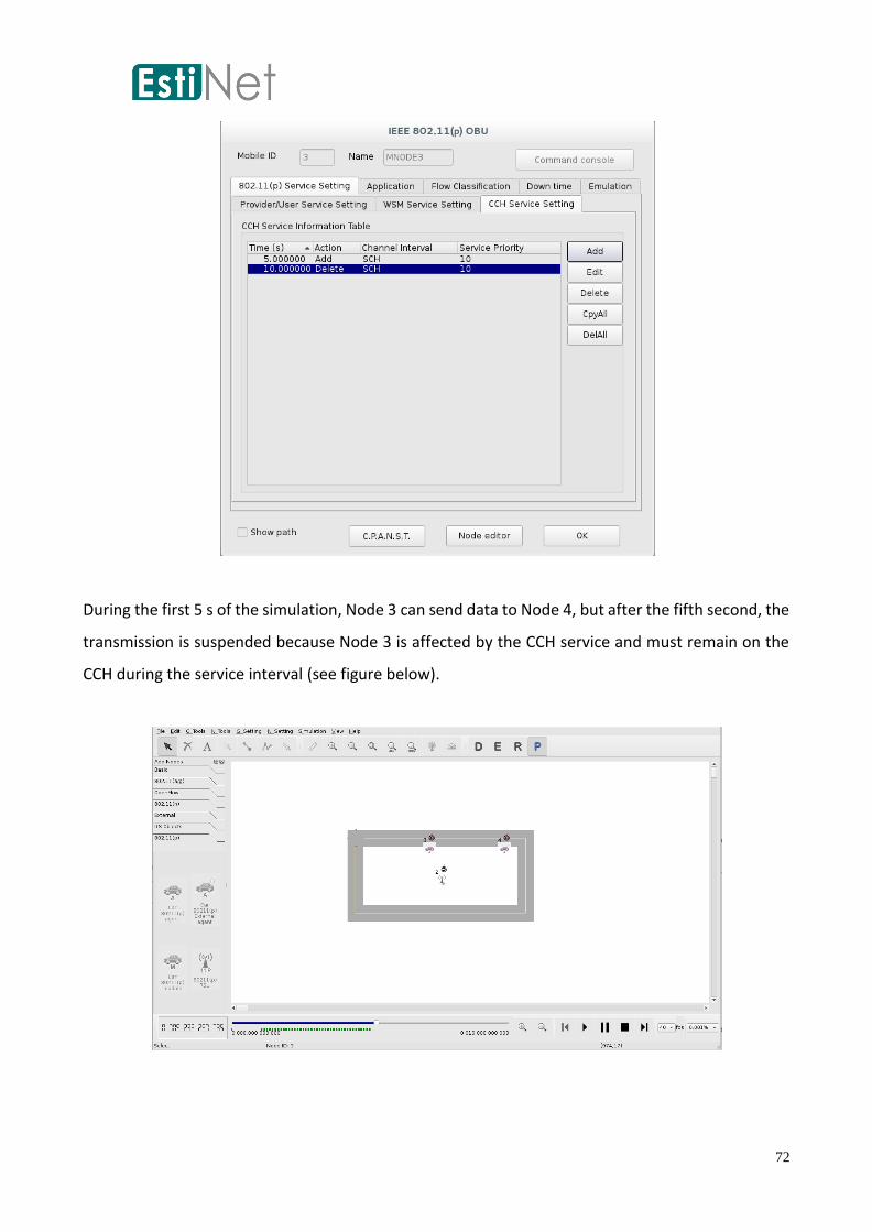
72
During the first 5 s of the simulation, Node 3 can send data to Node 4, but after the fifth second, the
transmission is suspended because Node 3 is affected by the CCH service and must remain on the
CCH during the service interval (see figure below).

73
WSM Service Settings
WSM service requests are WSM information that matches a specific PSID and are requested by a
higher layer. When a WAVE device receives a WSM, it compares whether the PSID of the WSM
corresponds to an application in the higher layer to determine whether to receive the packet. In the
topology discussed in the previous chapters, Node 3 must remain on the CCH to receive the WSM
packets (PSID 2; e.g., emergency road status messages) sent by RSU Node 2 during CCH service
suspension for the fifth to tenth seconds. Consequently, the following section describes how to add
a WSM service at Node 3 to receive the WSM packets.
First a WSM application is added at RSU Node 2 to transmit WSMs. Double click RSU Node 2. Input
“WSM-psid 2” in Application to define the PSID of this WSM packet as 2. Time should be set from
the fifth to the tenth second. The same settings are applied to Node 3.
After application settings for Node 3 are adjusted, select WSM Service Setting to prepare for the
activation of WSM services. The columns or fields in this tab are shown in the screenshot below and
then explained.

74
Time (s): This field refers to the point when specific WSM service information is processed during
the simulation.
Action: This field refers to the action that should be executed when the simulation time reaches a
designated point. Two WSM service actions are defined in the 1609.3 full use edition: Add and
Delete, and both are supported by EstiNet. Add creates a WSM service in 1609.3 MIB, and Delete
removes a WSM service from 1609.3 MIB.
PSID: This column is used to distinguish and identify the service ID. Currently, the length of a PSID
has been changed from an original fixed length of 4 octets to a variable value that is greater than or
equal to 5 octets but is still retained at a lower value. EstiNet supports a range of PSIDs from 0 to
999999999.
Therefore, the start time for Node 3 should be set to 5 s because this node must receive the WSM
packets (containing PSID 2) sent by Node 2 in the fifth second. Add WSM service with a PSID of 2.
Delete this service in the tenth second, as shown in the screenshot below.

75
During the first 5 s of the simulation, Node 3 sends data to Node 4, but after the fifth second. The
node is affected by the CCH service and must remain on the CCH during the service interval and
begin to transmit several WSM packets. As shown in the screenshot below, broadcast WSM packet
logs are found in the log file.

76
WSM and WSM_Forwarding Applications
IEEE 1609.3 specifications define WSMP as the Layer 3 and Layer 4 protocols that manage WSM
transmission and reception. Consequently, the most intuitive implementation method is to support
the WSMP and implement it in the core of Linux. However, because of the unique characteristics of
EstiNet, the implementation of WSMP in the Linux core requires modifying the current Linux core
network subsystems and socket application programming interface (API), necessitating intensive
effort and requiring complex subsequent maintenance.
To resolve this issue, EstiNet actualizes WSMP by implementing WSM transmission using user-level
C/C++ programs, which may be easily accessed by users executing WSM programs or
WSM_Forwarding during simulation. These two programs are included in the EstiNet installation
package and are automatically installed in the /usr/local/estinet/tools/ directory. The source codes
for these two programs are located in the $package/estinetse/application/its/VehicularNetwork/
directory. The $package represents the directory in which EstiNet source codes are installed. Thus,
these two programs can be easily modified to satisfy user needs.
In the previous chapter, the operation and use of the WSM application was discussed using WSM
services. Nevertheless, this application includes numerous other parameters that can be identified
using App. Usage in Application. The parameters are introduced as follows:
Operation input: WSM [-psid ###] [options]
PSID values or other option settings must be added to the end of the command string.
-psid ###: This value is required and enables WSM service to designate service WSM packets and
receive them. The value range that can be supported is 0 to 999999999.
Option values are as follows:
-ch ###: This value determines the channel on which WSM packets are transmitted. WSMs are
transmitted on either CCHs or SCHs; therefore, the channel settings that can be used are 172,174,
176, 178, 180, 182, and 184. If this option is disabled or is not chosen, WSMs are transmitted on any
channel.

77
-t ###: If this value is not defined, the default transmission frequency is 1 time/s. The measurement
unit for this value is a microsecond.
-w ###: This option enables the application to log received WSM packets. File names should be
attached to the parameter string.
-d ###: This option adjusts the data rate required for WSM packet transmission. Available data rates
are 3, 4.5, 6, 9, 12, 18, 24, and 27 Mbps.
-txp ###: This option determines the transmission power of WSM packet transmission. The power
setting ranges from -127 to 127 dBm.
-s: This option activates WSMP Safe Supplement. Methods listed here are from the appendix of the
1609.3 full use edition, and enable supplementary data for the transmitter to prevent data loss
during channel switching. Details are recorded in 1609.3 Appendix F [7].
-prio ###: This option is used to set user priority (UP). Users in the MAC layer are allocated to and
categorized into different queues and access categories according to UP. The UP default values for
best effort, background, video, and voice are 0 and 3, 1 and 2, 5 and 6, and 7 and 8, respectively.
-expt ###: This option determines the duration or period from the production to the termination or
expiration of a WSM packet. Packets exceeding the duration are abandoned in the WME or MAC
layers.
-dest ###: This option determines the destination MAC address of WSM packets. By default, WSM
packets are broadcast if no specific value is designated for this option.
Operation input for WSM_Forwarding is as follows: [-psid ###] [-options]. Parameter meanings are
the same as those for the WSM application described above.
The following is a WSM_Forwarding example. The RSU Node 2 in the center is connected to an
Internet Host Node 5, whereas Nodes 3 and 4 are on the road. The three nodes are covered by the
transmission range. The RSU attempts to forward the Internet packets transmitted from the host as
WSM packets to Nodes 3 and 4. The procedure is illustrated in the diagram below.

78
First adjust the settings for the forwarding program of RSU Node 2. After entering Node 2, select
Application, and input “WSM_Forwarding-psid 1,” to convert or package the forwarded Internet
packets as WSM packets with PSID 1, as shown in the screenshot below.
Then adjust the settings for the traffic command transmitted by Host Node 5. Double click Host
Node 5, and select Application to input commands. Designate the IP address as the IP of the RSU.
Note: The WSM_Forwarding program receives Internet packets using the special Port 5000;
therefore, “-p 5000” must be added to the command string to forward packets as WSMs. Please
refer to the screenshot below.

79
To continue, allow Nodes 3 and 4 to receive WSM packets with PSID 1. As shown in the screenshot
below, first adjust the WSM service, then click CpyAll to copy settings to all OBUs: Nodes 3 and 4.

80
Enter “WSM-psid 1” in the Application tab for Nodes 3 and 4 to enable higher layer applications to
receive lower layer WSM packets. The procedure is illustrated in the screenshot below.
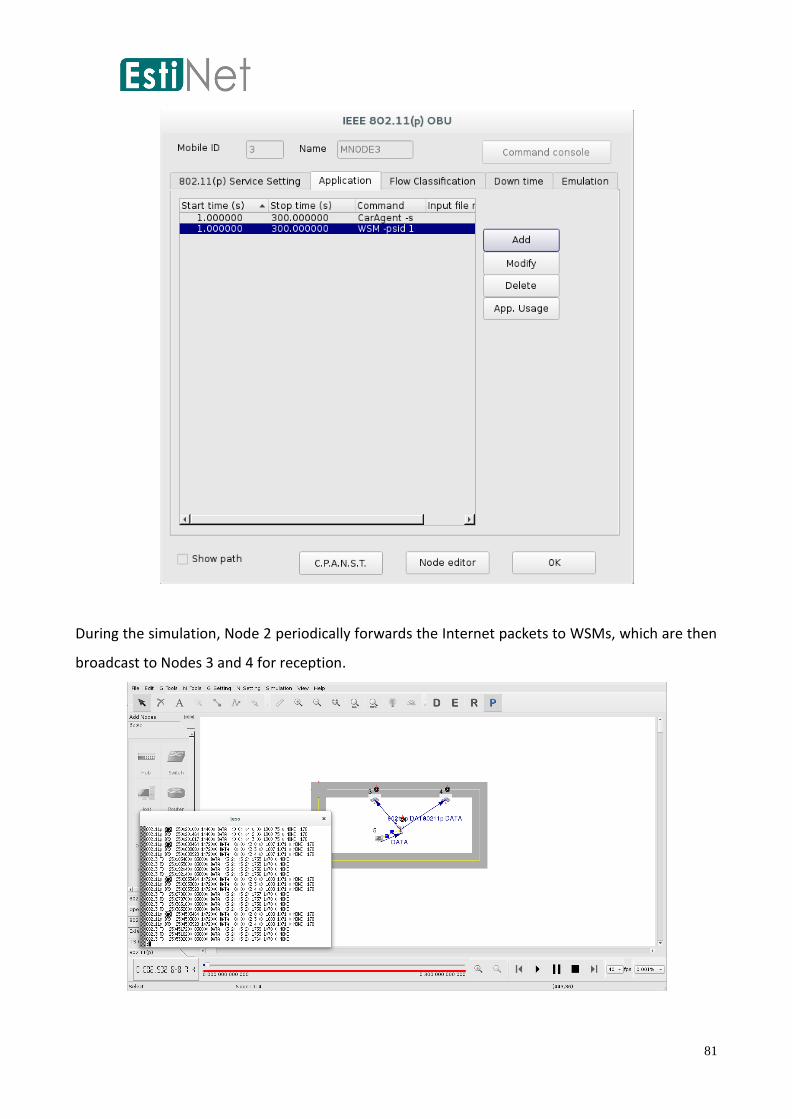
81
During the simulation, Node 2 periodically forwards the Internet packets to WSMs, which are then
broadcast to Nodes 3 and 4 for reception.

82
Introduction to the Multi-Interface Car
Multi-Interface car is a single ITS vehicle equipped with multiple communication interfaces. This type
of vehicle is represented as the colorful car icon listed in "ITS OBJECTS" GUI toolkit (left side of the
screen), as small car picture shown below. These communication interfaces are not only limited to
the same type of communication protocol, but also applied in different protocols. So far, in one ITS
car, EsiNet support 5 types of network interface card, which are ad-hoc mode of 80211a/g,
infrastructure of 80211a/g, ad-hoc mode of 80211n, infrastructure of 80211n, and 80211p in agent-
based car.
The setting procedures are illustrated in the screenshots below. First, deploy a road network, and
deploy multiple interface cars on the roads by clicking on the relevant car icon in the GUI toolbar.
Once one multiple interface car is deployed on the road, a dialog box will show up, and request for

83
the numbers and types of network interface cards in the multiple interface car. Currently, five types
of network interface cards are supported by EstiNet, as shown in the following figure. From the
figure below, a multiple interface car is equipped with one IEEE 802.11a/g ad hoc mode, one 802.11n
ad hoc mode, and two IEEE 802.11p agent-based network interface cards.
If you want to add/delete numbers of interface cards in the multi-interface car, to double click the
car icon in D mode. A dialog will pop out as figure shown below, press “Add” button to create
more interfaces in the node, or press “Delete” button to remove selected interface card.

84
Double click Node 2(Multi-Interface Car) in the E Mode, the following dialog box will show up, which
contains two tabs. The Application tab includes a “CarAgent - s” command, which controls vehicle
driving intelligence.
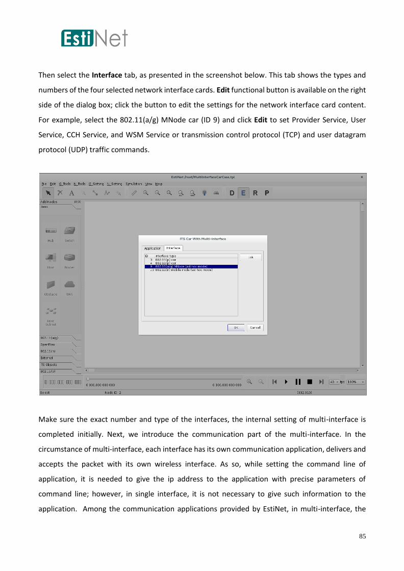
85
Then select the Interface tab, as presented in the screenshot below. This tab shows the types and
numbers of the four selected network interface cards. Edit functional button is available on the right
side of the dialog box; click the button to edit the settings for the network interface card content.
For example, select the 802.11(a/g) MNode car (ID 9) and click Edit to set Provider Service, User
Service, CCH Service, and WSM Service or transmission control protocol (TCP) and user datagram
protocol (UDP) traffic commands.
Make sure the exact number and type of the interfaces, the internal setting of multi-interface is
completed initially. Next, we introduce the communication part of the multi-interface. In the
circumstance of multi-interface, each interface has its own communication application, delivers and
accepts the packet with its own wireless interface. As so, while setting the command line of
application, it is needed to give the ip address to the application with precise parameters of
command line; however, in single interface, it is not necessary to give such information to the
application. Among the communication applications provided by EstiNet, in multi-interface, the
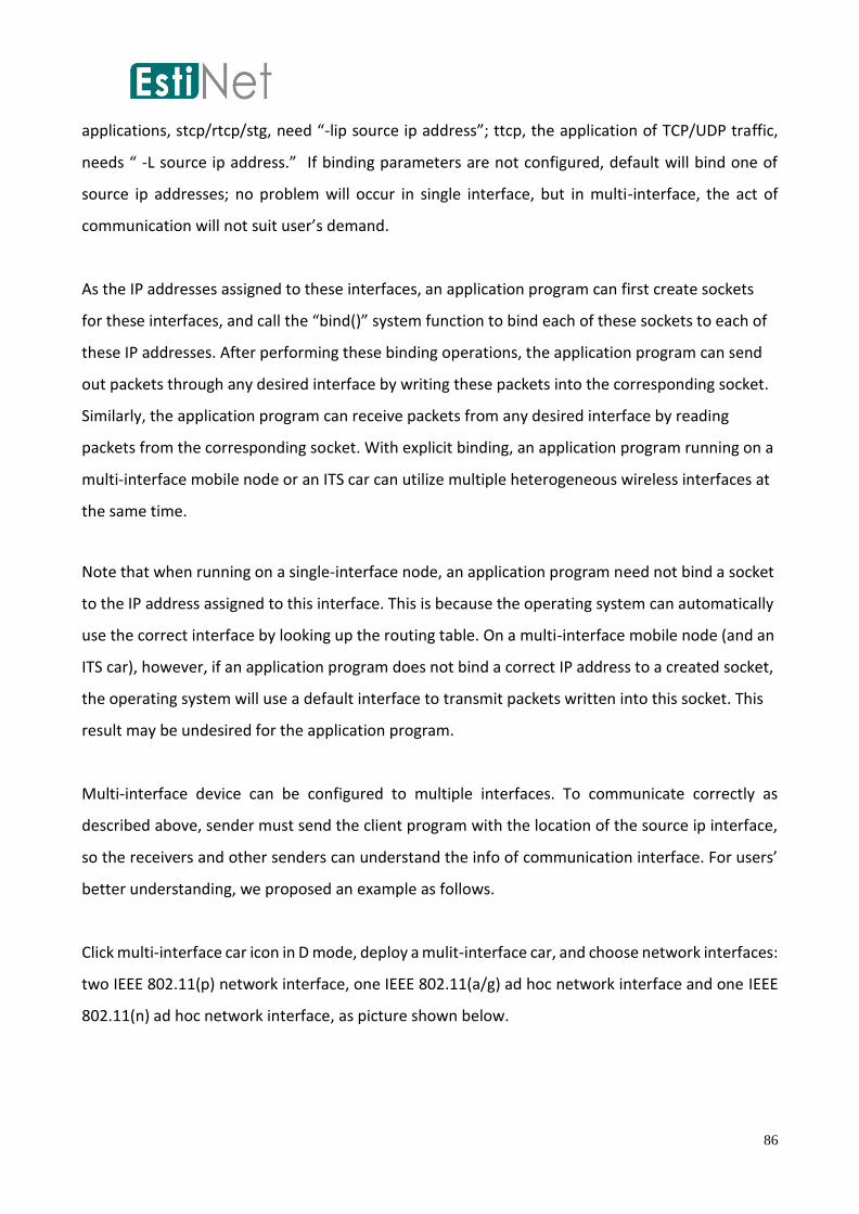
86
applications, stcp/rtcp/stg, need “-lip source ip address”; ttcp, the application of TCP/UDP traffic,
needs “ -L source ip address.” If binding parameters are not configured, default will bind one of
source ip addresses; no problem will occur in single interface, but in multi-interface, the act of
communication will not suit user’s demand.
As the IP addresses assigned to these interfaces, an application program can first create sockets
for these interfaces, and call the “bind()” system function to bind each of these sockets to each of
these IP addresses. After performing these binding operations, the application program can send
out packets through any desired interface by writing these packets into the corresponding socket.
Similarly, the application program can receive packets from any desired interface by reading
packets from the corresponding socket. With explicit binding, an application program running on a
multi-interface mobile node or an ITS car can utilize multiple heterogeneous wireless interfaces at
the same time.
Note that when running on a single-interface node, an application program need not bind a socket
to the IP address assigned to this interface. This is because the operating system can automatically
use the correct interface by looking up the routing table. On a multi-interface mobile node (and an
ITS car), however, if an application program does not bind a correct IP address to a created socket,
the operating system will use a default interface to transmit packets written into this socket. This
result may be undesired for the application program.
Multi-interface device can be configured to multiple interfaces. To communicate correctly as
described above, sender must send the client program with the location of the source ip interface,
so the receivers and other senders can understand the info of communication interface. For users’
better understanding, we proposed an example as follows.
Click multi-interface car icon in D mode, deploy a mulit-interface car, and choose network interfaces:
two IEEE 802.11(p) network interface, one IEEE 802.11(a/g) ad hoc network interface and one IEEE
802.11(n) ad hoc network interface, as picture shown below.
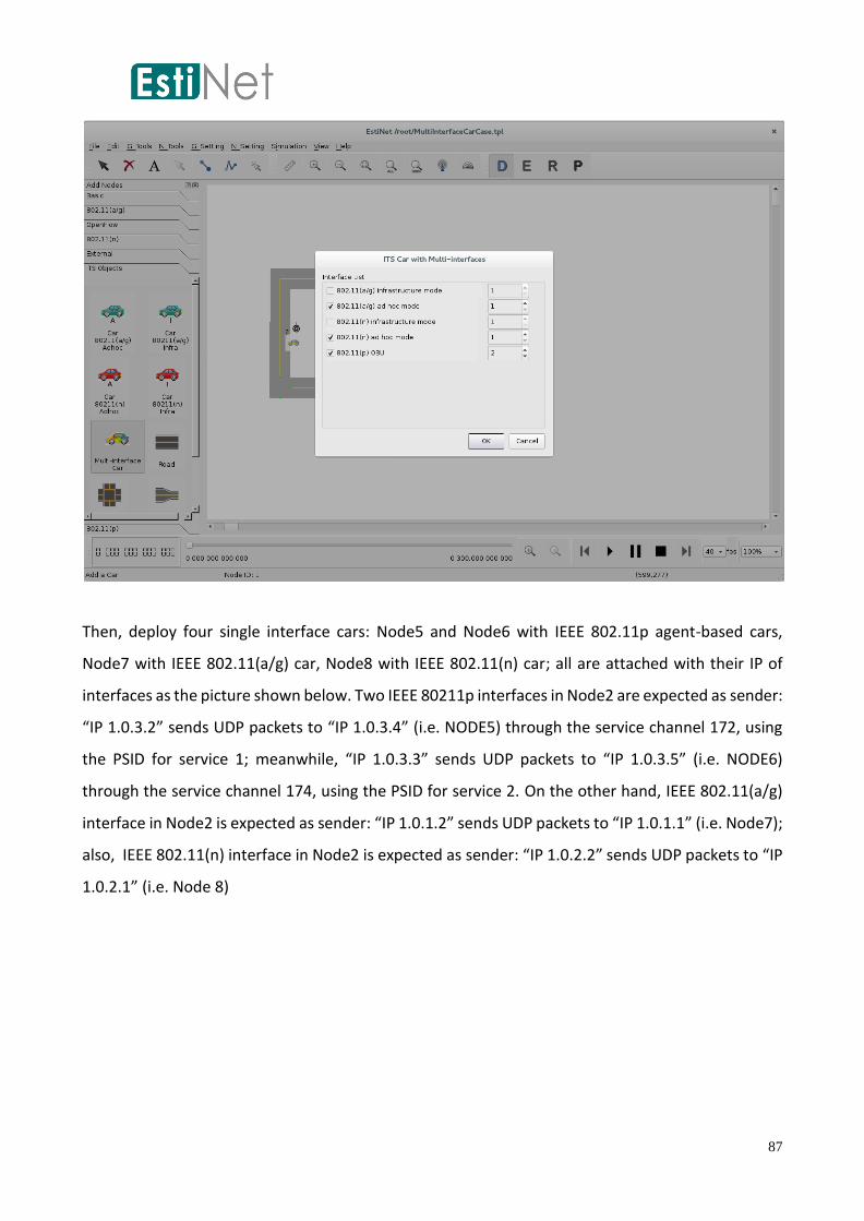
87
Then, deploy four single interface cars: Node5 and Node6 with IEEE 802.11p agent-based cars,
Node7 with IEEE 802.11(a/g) car, Node8 with IEEE 802.11(n) car; all are attached with their IP of
interfaces as the picture shown below. Two IEEE 80211p interfaces in Node2 are expected as sender:
“IP 1.0.3.2” sends UDP packets to “IP 1.0.3.4” (i.e. NODE5) through the service channel 172, using
the PSID for service 1; meanwhile, “IP 1.0.3.3” sends UDP packets to “IP 1.0.3.5” (i.e. NODE6)
through the service channel 174, using the PSID for service 2. On the other hand, IEEE 802.11(a/g)
interface in Node2 is expected as sender: “IP 1.0.1.2” sends UDP packets to “IP 1.0.1.1” (i.e. Node7);
also, IEEE 802.11(n) interface in Node2 is expected as sender: “IP 1.0.2.2” sends UDP packets to “IP
1.0.2.1” (i.e. Node 8)
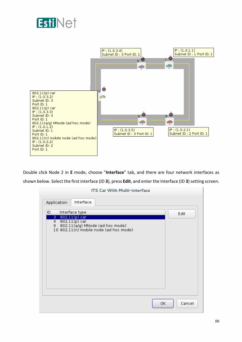
88
Double click Node 2 in E mode, choose "Interface" tab, and there are four network interfaces as
shown below. Select the first interface (ID 3), press Edit, and enter the Interface (ID 3) setting screen.

89
Setting ID 3 as a provider role, Provider Service is added by pressing the "Add" button in provider
service information table shown in the following figure.
Set the PSID value of Provider Service to 1, the channel id to 172, and keep the other parameters to
the default value as figure shown below. Press "OK" button after your setting, you can view Provider
Service in the provider service information table.

90
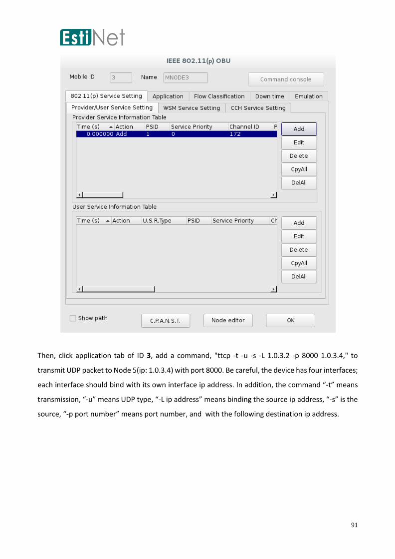
91
Then, click application tab of ID 3, add a command, "ttcp -t -u -s -L 1.0.3.2 -p 8000 1.0.3.4," to
transmit UDP packet to Node 5(ip: 1.0.3.4) with port 8000. Be careful, the device has four interfaces;
each interface should bind with its own interface ip address. In addition, the command “-t” means
transmission, “-u” means UDP type, “-L ip address” means binding the source ip address, “-s” is the
source, “-p port number” means port number, and with the following destination ip address.

92

93
Return to the "Interface" tab of Node 2, select ID 4, and press the "Edit" button as the following
dialog.
The second interface (ID 4) also acts as a provider role, so we need to add Provider Service. To click
"Add" button of provider service information table to add a Provider Service. The PSID of the
provider service is 2, and the channel id is 174. Other settings to the default value. Finally, to click
"OK", we can see the provider service in the provider service information table as below figure.

94

95

96
Then, click application tab of ID 4, add a command, "ttcp -t -u -s -L 1.0.3.3 -p 8001 1.0.3.5" to transmit
UDP packet to Node 6(ip: 1.0.3.5) with port 8001. Be careful, the device has four interfaces; each
interface should bind with its own interface ip address.

97
Return to the "Interface" tag of Node 2, select ID 9 and press the "Edit" button as the following
dialog.

98
Then, click application tab of ID 9, add a command, "ttcp -t -u -s -L 1.0.1.2 -p 8002 1.0.1.1" to transmit
UDP packet to Node 7(ip: 1.0.1.1) with port 8002. Be careful, the device has four interfaces; each
interface should bind with its own interface ip address.
Return to the "Interface" tag of Node 2, to select ID 10 and press the "Edit" button as the following
dialog.

99
Then, click application tab of ID 10, add a command, "ttcp -t -u -s -L 1.0.2.2 -p 8003 1.0.2.1" to
transmit UDP packet to Node 8(ip: 1.0.2.1) with port 8003. Be careful, the device has four interfaces;
each interface should bind with its own interface ip address.

100
Now, the configuration of four interfaces in the Multi-Interface (Node 2) is completed. All of the four
interfaces in Node 2 are senders, then we configure the interface settings as receiver in Node 5,
Node 6, Node 7 and Node 8.
The receiving nodes, in this example, Node 5, Node6, Node 7 and Node 8, act as the receiving end.
The Node 5 and Node 6 act as user role in IEEE 802.11p/1609.3. First, double click on Node 5, and
pop a dialog as the following figure.
Setting Node 5 as a user role, User Service is added by pressing the "Add" button in user service
information table shown in the following figure.

101
Set the PSID value of User Service to 1, the other setting to the default value as figure shown below.
Press "OK" button after your setting, you can view user service in user service information table.

102
Then, click application tab of Node 5, add a command, "ttcp -r -u -s -p 8000 -w log1" to receive UDP
packet from Node 2(ip: 1.0.3.2) with port 8000. In addition, the command "-r" means receive mode,
"-u" means UDP type, "-s" is sink, "-p port number" means port number, and “-w filename” means
log per-second throughput to file (log1).

103
Setting Node 6 as a user role too. User Service is added by pressing the "Add" button in user service
information table shown in the following figure.

104
Set The PSID of User Service to 2 and keep the other parameters to the default value as figure shown
below. Press "OK" button after your setting, you can view User Service in user service information
table.

105

106
Then, click application tab of Node 6, add a command, "ttcp -r -u -s -p 8001 -w log2" to receive UDP
packet from Node 2(ip: 1.0.3.3) with port 8001.

107
Double click Node 7 in E mode, and then click application tab and add a command, "ttcp -r -u -s -p
8002 -w log3" to receive UDP packet from Node 2(ip: 1.0.1.2) with port 8002.
Finally, double click Node 8 in E mode, and then click application tab and add a command, "ttcp -r -
u -s -p 8003 -w log4" to receive UDP packet from Node 2(ip: 1.0.2.2) with port 8003.

108
After the setup is complete, enter the R mode to start the simulation. After successfully simulation,
you will see the following screen with four sets of traffic transmission, and also the four log files,
which you can see the throughput of each interface.
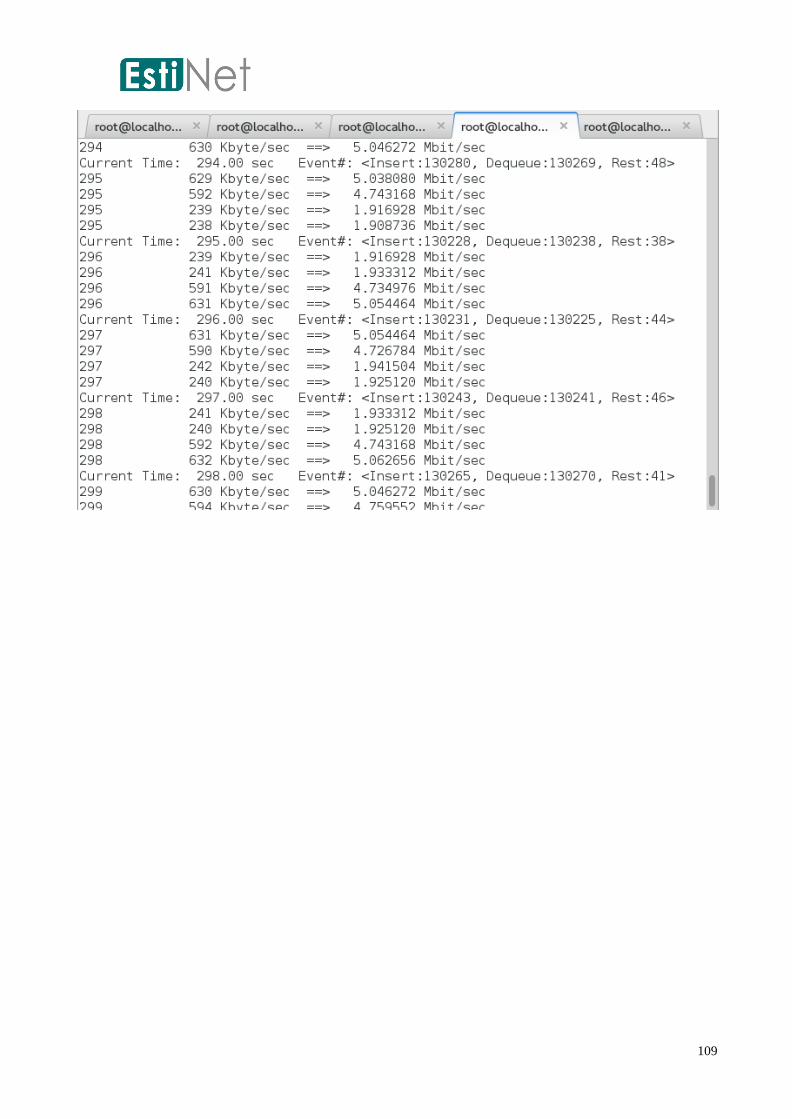
109
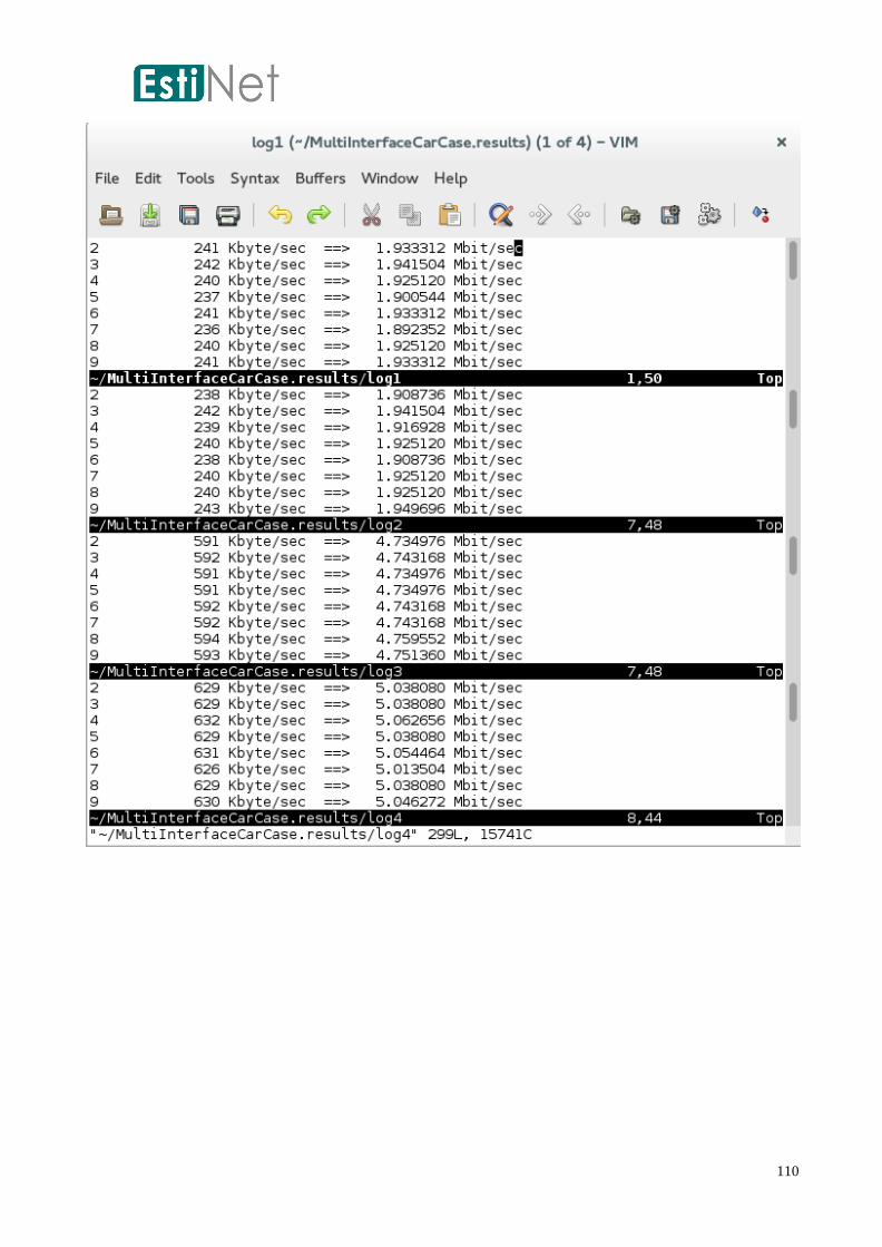
110
111
Conclusion
The chapters in this manual provide concrete descriptions of the procedures for constructing
wireless vehicular network environments using EstiNet. Using the GUI of EstiNet, various types of
infrastructure, such as ITS communications vehicles, road networks, intersections, and landmarks,
are quickly and easily deployed. Through the EstiNet simulation engine and vehicular intelligent
control applications, intelligent transportation vehicles drive in a vehicular network environment
that has low latency or delays and real-time notification through the adoption of WAVE/ DSRC
technology. In addition, the simulation results can encourage and inspire more study topics on
VANET regarding both research and applications of V2V and V2R [1], [2], [3]. From an industry
perspective, by using the EstiNet VANET for simulation before mass producing products,
manufacturers can enhance their understanding of simulation effects for IEEE 802.11p/1609
technology specifications in specific vehicular environments, such as urban areas with high
congestion and traffic density or tourist attractions with numerous landmarks and scenic locations.
Simulations assist industries in reducing development time during research and development for
products, decreasing technical complexity and lowering development costs. Furthermore,
simulation research can be used to develop and discover additional application services for people,
vehicles, roads, and various environments. This process can allow industries to realize increased
business opportunities and can finally encourage greater benefits and contributions for society.

112
References
[1] S.Y. Wang and Y.W. Li, “Evaluations of Intelligent Traffic Signal Control Algorithms under Realistic
Landmark-‐based Traffic Patterns over the NCTUns Network Simulator,” IEEE ITSC 2012
(International Conference on Intelligent Transportation Systems), September 16 -‐ 19, 2012,
Anchorage, Alaska, USA.
[2] S.Y. Wang and C.C. Lin, “NCTUns 5.0: A Network Simulator for IEEE 802.11(p) and 1609 Wireless
Vehicular Network Researches,” the 2nd IEEE International Symposium on Wireless Vehicular
Communications(WiVeC 2008).
[3]S.Y. Wang, C.L. Chou, Y.H. Chiu, Y.S. Tseng, M.S. Hsu, Y.W. Cheng, W.L. Liu, and T.W. Ho, “NCTUns
4.0: An Integrated Simulation Platform for Vehicular Traffic, Communication , and Network
Researches,” 1st IEEE International Symposium on Wireless Vehicular Communications, September
30 -‐ October 1, 2007, Baltimore, MD, USA.
[4]”IEEE Std 802.11p-‐2010 (Amendment to IEEE Std 802.11-‐2007 as amended by IEEE Std 802.11k-‐
2008, IEEE Std 802.11r-‐2008, IEEE Std 802.11y-‐2008, IEEE Std
802.11n-‐2009, and IEEE Std 802.11w-‐2009,” July 15, 2010
[5]”IEEE Std 802.11-‐2007 (Revision of IEEE Std 802.11-‐1999),” June 12, 2007
[6] “ IEEE P1609.0™/D3.02.0 Draft Guide for Wireless Access in Vehicular
Environments (WAVE) -‐ Architecture,”, February 2012
[7]”IEEE Std 1609.3-‐2010, IEEE Standard for Wireless Access in Vehicular
Environments(WAVE) –Networking Services“, December 30, 2010
[8]” IEEE Std 1609.4-‐2010, IEEE Standard for Wireless Access in Vehicular
Environments (WAVE) – Multi-‐channel Operation,” February 7, 2011.
[9]”Design and Implementation of a more Realistic Radio Propagation Model for
Vehicular Networks over the NCTUns Network Simulator”, WCNC, March 2011. [10]
http://www.openstreetmap.org/