2015-2016 Altima; I4 with DTC P0776 Stored · 2015-2016 Altima (L33) with 4 cylinder only CVT . ......
83
1/83 Classification: Reference: Date: AT16-001 NTB16-110 November 14, 2016 2015-2016 ALTIMA; 4 CYLINDER WITH DTC P0776 STORED APPLIED VEHICLE: APPLIED TRANSMISSTION: 2015-2016 Altima (L33) with 4 cylinder only CVT IF YOU CONFIRM The MIL is ON with DTC P0776 (PC SOLENOID B – Pressure Control Solenoid “B” Performance/Stuck OFF) stored. NOTE: If this issue should occur: P1715 (INPUT SPEED SENSOR) may be stored with DTC P0776. The vehicle may hesitate and/or have reduced power. ACTION Refer to the Repair Flow Chart on page 2 for CVT repair. CAUTION: Always handle the CVT and component assemblies carefully and with the appropriate lifting tools. Pages 53 and 82 must be printed and attached to the repair order. IMPORTANT: The purpose of ACTION (above) is to give you a quick idea of the work you will be performing. You MUST closely follow the entire SERVICE PROCEDURE as it contains information that is essential to successfully completing this repair. Nissan Bulletins are intended for use by qualified technicians, not 'do-it-yourselfers'. Qualified technicians are properly trained individuals who have the equipment, tools, safety instruction, and know-how to do a job properly and safely. NOTE: If you believe that a described condition may apply to a particular vehicle, DO NOT assume that it does. See your Nissan dealer to determine if this applies to your vehicle.
Transcript of 2015-2016 Altima; I4 with DTC P0776 Stored · 2015-2016 Altima (L33) with 4 cylinder only CVT . ......

1/83
Classification: Reference: Date:
AT16-001 NTB16-110 November 14 , 2016
2015-2016 ALTIMA; 4 CYLINDER WITH DTC P0776 STORED APPLIED VEHICLE: APPLIED TRANSMISSTION:
2015-2016 Altima (L33) with 4 cylinder only CVT
IF YOU CONFIRM The MIL is ON with DTC P0776 (PC SOLENOID B – Pressure Control Solenoid “B” Performance/Stuck OFF) stored.
NOTE: If this issue should occur:
P1715 (INPUT SPEED SENSOR) may be stored with DTC P0776.
The vehicle may hesitate and/or have reduced power. ACTION
Refer to the Repair Flow Chart on page 2 for CVT repair.
CAUTION: Always handle the CVT and component assemblies carefully and with the appropriate lifting tools.
Pages 53 and 82 must be printed and attached to the repair order.
IMPORTANT: The purpose of ACTION (above) is to give you a quick idea of the work you will be performing. You MUST closely follow the entire SERVICE PROCEDURE as it contains information that is essential to successfully completing this repair.
Nissan Bulletins are intended for use by qualified technicians, not 'do-it-yourselfers'. Qualified technicians are properly trained individuals who have the equipment, tools, safety instruction, and know-how to do a job properly and safely. NOTE: If you believe that a described condition may apply to a particular vehicle, DO NOT assume that it does. See your Nissan dealer to determine if this applies to your vehicle.

Repair Flow Chart
Evidence of CVT belt slippage
Remove the control valve (valve body) and
inspect the belt
The CVT belt / pulley
checks out OK
Replace the sub assembly Page 16
NOTE: Valve body will also
be replaced with sub-assembly
Replace the valve body only
Page 64
For model year 2015 vehicles only:
Check TCM part number and if needed perform reprogramming
Page 71
MIL ON with DTC P0776 (P1715 may be stored with
DTC P0776)
Vehicle may hesitate or have reduced power
2/83 NTB16-110

Table of Contents Required Tools / Material
Essential Tools
Weights
Precautions when Disassembling a CVT Assembly
Control Valve (Valve Body) Removal and CVT Belt Inspection
CVT Assembly Removal
Remove the Converter Housing, Oil Seals, Oil Pump Cover, Oil Pump and Oil Filter
Clean the CVT case surfaces
Clean the Oil Passages in the CVT Case, Oil Pump Cover, and CVT Filter Area
New Pump Installation
Replace the Side Cover – Pulleys and Belt (sub-assembly)
Clutch Total Endplay Adjustment – Thrust Bearing Selection
Clean the Converter Housing Passages
CVT Reassembly
Control Valve (Valve Body) Strainer and Pan Installation
Install the CVT Assembly
Reprogram TCM
Trouble Shooting
PARTS INFORMATION
CLAIMS INFORMATION
PARTS KITS REFERENCE TABLE
page 4
page 4
page 5
page 6
page 7
page 16
page 19
page 27 page 28
page 30
page 32
page 49
page 54
page 56
page 64
page 70
page 71
page 78
page 80
page 81
page 82
3/83 NTB16-110
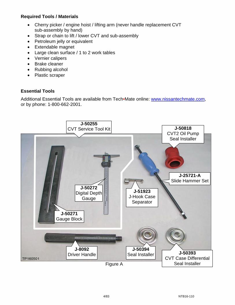
Required Tools / Materials
Cherry picker / engine hoist / lifting arm (never handle replacement CVT sub-assembly by hand)
Strap or chain to lift / lower CVT and sub-assembly Petroleum jelly or equivalent Extendable magnet Large clean surface / 1 to 2 work tables Vernier calipers Brake cleaner Rubbing alcohol Plastic scraper
Essential Tools
Additional Essential Tools are available from Tech•Mate online: www.nissantechmate.com, or by phone: 1-800-662-2001.
Figure A
J-50271 Gauge Block
J-51923 J-Hook Case
Separator
J-50394 Seal Installer J-50393
CVT Case Differential Seal Installer
J-25721-A Slide Hammer Set
J-50818 CVT2 Oil Pump
Seal Installer
J-50272 Digital Depth
Gauge
J-50255 CVT Service Tool Kit
J-8092 Driver Handle
4/83 NTB16-110

Essential Tools (continued)
J-51959 Guide Pins
Figure B
J-51909 Lifting Fixture (side cover) J-51595-1
Eyelet & linkage
J-51595 Lifting Fixture (top)
Figure C Figure D Tech Cam J-51951
Lens swab J-51963 (not part of J-51951)
Remove protective film before first use
Figure E
Additional Tech Cam J-51951 kits or components are available from Tech•Mate.
Weights
CVT assembly: 300 lbs. approximately CVT sub-assembly: 65 lbs. approximately
5/83 NTB16-110

SERVICE PROCEDURE Precautions when Disassembling a CVT Assembly Transmissions are vulnerable to particles (dust, metal, lint, etc.).
When disassembling a CVT, make sure your work environment (shop, workbench, etc.), transmission area (sub-frame, oil pan, harness connector, etc.), and your hands are free of contamination. IMPORTANT:
Wash and clean the exterior of the CVT assembly prior to disassembling.
CAUTION: Cover all air breather and drive shaft holes to prevent water intrusion. Apply rust penetrant to locator / dowel pins on torque converter housing and side
cover of CVT and allow to soak as needed. Refrigerating oil seals may help in assembly (axle and T/C seals). Only disassemble those parts which are mentioned in this bulletin. Make sure all parts are clean prior to assembling / installing.
Unpack service parts just before installation.
Figure F
Figure G
Store the related parts that have been removed separately to prevent being mixed up; small cups can be used.
IMPORTANT: The CVT unit “wiring harness connector” will be reused during this procedure. The wiring harness can be disconnected from the valve body at the wiring harness connector and remain in the CVT. Wiring harness
connector
6/83 NTB16-110

Control Valve (Valve Body) Removal and CVT Belt Inspection 1. Write down all radio station presets.
Presets 1 2 3 4 5 6 AM FM 1 FM 2 SAT 1 SAT 2/3 Bass Treble Balance Fade Speed Sen. Vol.
2. Disconnect both battery cables, negative cable first. 3. Remove the valve body.
Before lifting the vehicle;
Place the transmission gear selector in Neutral.
Refer to the appropriate ESM, section TM – Transaxle & Transmission, for valve body removal.
NOTE: The number ‘7’ is on the head of all bolts that need to be removed for valve body removal. Do not remove any bolt that does not have the number ‘7’.
CAUTION: Never allow any chemicals or fluids other than NS-3 CVT fluid or equivalent to enter the CVT assembly. Never allow any foreign debris, dust, dirt, etc. to enter the CVT assembly.
For additional information, see video # 544: “CVT Belt Inspection”. This video is
located under the TECH TRAINING GARAGE VIDEOS tab in Virtual Academy.
7/83 NTB16-110

Exploded View
(Total of 9 bolts)
Figure 1A
1. Transaxle assembly 2. Terminal cord assembly 3. CVT fluid temperature sensor bracket
4. Control valve 5. Bracket 6. O-ring 7. New-style oil strainer assembly 8. Old-style oil strainer assembly 9. Oil pan gasket 10. Oil pan 11. Drain plug 12. Drain plug gasket 13. Magnet 14. Spring washer 15. Manual plate 16.
19. Lip seal
O-ring 17. Snap ring 18. Overflow plug
8/83 NTB16-110
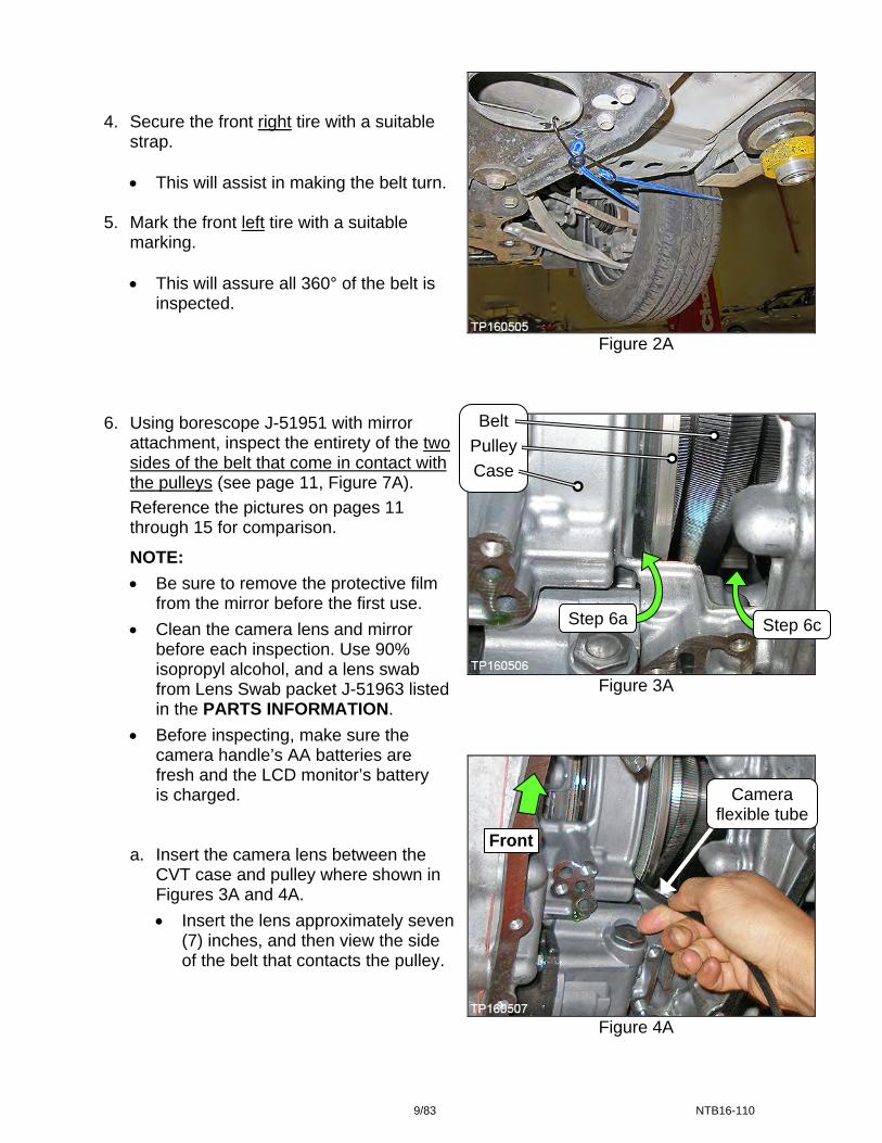
4. Secure the front right tire with a suitable
strap.
This will assist in making the belt turn. 5. Mark the front left tire with a suitable
marking.
This will assure all 360° of the belt is inspected.
6. Using borescope J-51951 with mirror
attachment, inspect the entirety of the two sides of the belt that come in contact with the pulleys (see page 11, Figure 7A).
Reference the pictures on pages 11 through 15 for comparison.
NOTE:
Be sure to remove the protective film from the mirror before the first use.
Clean the camera lens and mirror before each inspection. Use 90% isopropyl alcohol, and a lens swab from Lens Swab packet J-51963 listed in the PARTS INFORMATION.
Before inspecting, make sure the camera handle’s AA batteries are fresh and the LCD monitor’s battery is charged.
a. Insert the camera lens between the CVT case and pulley where shown in Figures 3A and 4A.
Insert the lens approximately seven(7) inches, and then view the side of the belt that contacts the pulley.
Figure 2A
Belt
Pulley
Case
Step 6a Step 6c
Figure 3A
Camera flexible tube
Front
Figure 4A
9/83 NTB16-110
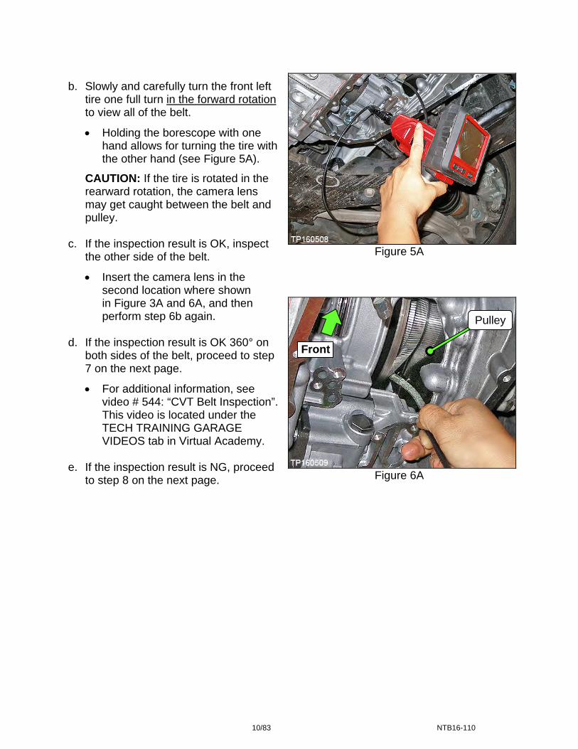
b. Slowly and carefully turn the front left tire one full turn in the forward rotation to view all of the belt.
Holding the borescope with one hand allows for turning the tire with the other hand (see Figure 5A).
CAUTION: If the tire is rotated in the rearward rotation, the camera lens may get caught between the belt and pulley.
c. If the inspection result is OK, inspect
the other side of the belt.
Insert the camera lens in the second location where shown in Figure 3A and 6A, and then perform step 6b again.
d. If the inspection result is OK 360° on
both sides of the belt, proceed to step 7 on the next page.
For additional information, see video # 544: “CVT Belt Inspection”. This video is located under the TECH TRAINING GARAGE VIDEOS tab in Virtual Academy.
e. If the inspection result is NG, proceed
to step 8 on the next page.
Figure 5A
Pulley
Front
Figure 6A
10/83 NTB16-110

7. If the belt inspection result is OK, replace only the valve body and reprogram TCM.
For valve body replacement, go to page 64, Control Valve (Valve Body) Installation.
8. If the belt inspection result is NG, replace the CVT sub-assembly, valve body and
reprogram TCM.
Go to CVT Assembly Removal, page 16.
Inspect these sides
Do not inspect these sides
Figure 7A
11/83 NTB16-110
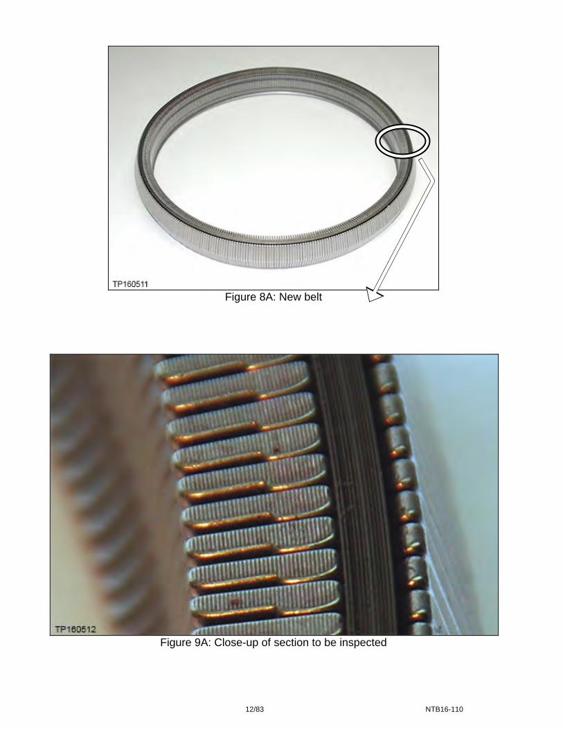
Figure 8A: New belt
Figure 9A: Close-up of section to be inspected
12/83 NTB16-110

Pictures in Figures 10A and 11A were taken with borescope J-51951.
OK
Visual lines
Figure 10A: Belt is OK
OK
Visual lines
Figure 11A: Belt is OK
13/83 NTB16-110

Figure 12A: Example of NG belt
NG
NG
Lines “smeared”
Scuffing
Figure 13A: Example of NG belt
14/83 NTB16-110

Pictures in Figures 14A-16A were taken with borescope J-51951.
Figure 14A: Example of NG belt
Figure 15A: Example of NG belt
NG
NG
NG
Figure 16A: Example of NG belt
15/83 NTB16-110
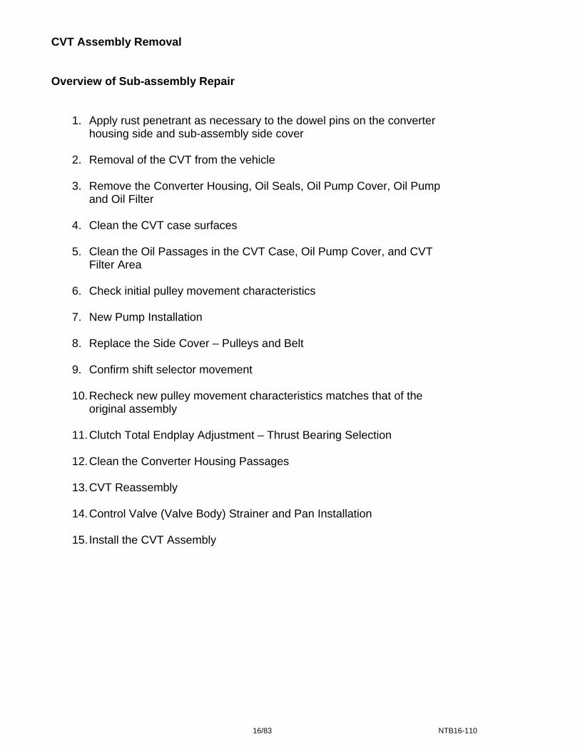
CVT Assembly Removal Overview of Sub-assembly Repair
1. Apply rust penetrant as necessary to the dowel pins on the converter housing side and sub-assembly side cover
2. Removal of the CVT from the vehicle
3. Remove the Converter Housing, Oil Seals, Oil Pump Cover, Oil Pump
and Oil Filter
4. Clean the CVT case surfaces
5. Clean the Oil Passages in the CVT Case, Oil Pump Cover, and CVT Filter Area
6. Check initial pulley movement characteristics
7. New Pump Installation
8. Replace the Side Cover – Pulleys and Belt
9. Confirm shift selector movement
10. Recheck new pulley movement characteristics matches that of the
original assembly
11. Clutch Total Endplay Adjustment – Thrust Bearing Selection
12. Clean the Converter Housing Passages
13. CVT Reassembly
14. Control Valve (Valve Body) Strainer and Pan Installation
15. Install the CVT Assembly
16/83 NTB16-110

1. Temporarily install the oil pan gasket and oil pan with four oil pan bolts to corners of the
oil pan, hand tight (Figure 1B).
NOTE: If the control valve has not yet been reinstalled, it is not necessary to do so. A new one will be installed later in this service procedure.
Figure 1B
2. Remove the CVT from the vehicle.
Refer to the Electronic Service Manual (ESM), section TM-Transaxle & Transmission for removal information.
17/83 NTB16-110
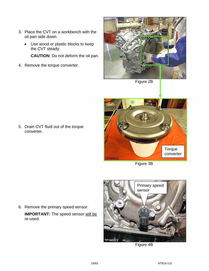
3. Place the CVT on a workbench with the
oil pan side down.
Use wood or plastic blocks to keep the CVT steady.
CAUTION: Do not deform the oil pan. 4. Remove the torque converter. 5. Drain CVT fluid out of the torque
converter. 6. Remove the primary speed sensor.
IMPORTANT: The speed sensor will be re-used.
Figure 2B
Figure 3B
Torque converter
Primary speed sensor
Figure 4B
18/83 NTB16-110

Remove the Converter Housing, Oil Seals, Oil Pump Cover, Oil Pump and Oil Filter
1. Remove all 23 converter housing
mounting bolts (see Figure 1C).
Loosen the bolts with hand tools only.
NOTE:
o These bolts will be replaced with new ones and will not be reused.
o Apply rust remover to the dowel pins if needed.
Dowel Pin
Figure 1C 2. Separate and then remove the converter housing from the CVT case.
Use Slide Hammer J-25721-A and Slide Hammer Bolt J-50255-UPD with J-Hook J-51923 at the cut out areas similar to the one shown in Figure 2C and Figure 3C.
CAUTION: DO NOT use a pry-bar, chisel, etc. to separate the side cover from the CVT case.
J-25721-A -----
J-50255-UPD-----
J-51923
One of three cutout areas
Figure 2C Figure 3C
19/83 NTB16-110

3. Note the location of the pin shown in Figure 4C.
CAUTION: This pin can slip out during movement of the CVT while converter housing is removed.
Figure 4C
Figure 5C
5. Carefully remove the reduction gear assembly (Figure 6C). 6. Carefully remove the differential assembly (Figure 7C).
4. Remove the O-ring from the input shaft.
This O-ring will be replaced with a new one.
O-ring
Reduction gear assembly
Differential assembly
Figure 6C Figure 7C
20/83 NTB16-110
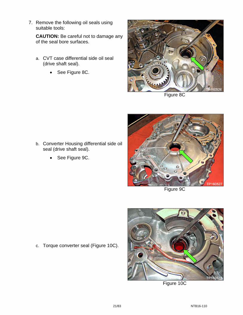
Figure 8C
Figure 9C
Figure 10C
7. Remove the following oil seals using suitable tools:
CAUTION: Be careful not to damage any of the seal bore surfaces.
a. CVT case differential side oil seal (drive shaft seal).
See Figure 8C.
b. Converter Housing differential side oil seal (drive shaft seal).
See Figure 9C.
c. Torque converter seal (Figure 10C).
21/83 NTB16-110

8. Remove the two (2) nuts from baffle
plate A, and then remove baffle plate A (see Figure 11C).
CAUTION: To avoid rounding off these nuts, it is best to use a 3/8 inch drive 6-pt 10 mm socket.
Baffle plate A
Baffle plate nuts
Figure 11C 9. Remove the oil pump chain, driven and drive sprockets as one assembly (Figure 12C).
Spread the snap ring to remove sprocket (Figure 13C).
IMPORTANT: The drive sprocket has a specific top and bottom. Keep the sprockets and chain together after removed.
Driven sprocket
Drive sprocket
Snap ring Oil pump chain
Figure 12C Figure 13C
22/83 NTB16-110
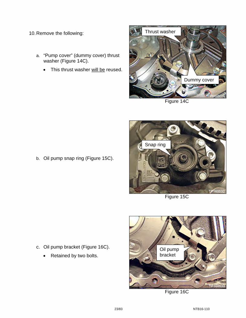
Thrust washer 10. Remove the following:
a. “Pump cover” (dummy cover) thrust washer (Figure 14C).
This thrust washer will be reused.
Dummy cover
Figure 14C
Snap ring
b. Oil pump snap ring (Figure 15C).
Figure 15C
c. Oil pump bracket (Figure 16C). Oil pump bracket
Retained by two bolts.
Figure 16C
23/83 NTB16-110

11. Remove the three bolts from baffle plate
B, and then remove baffle plate B (Figure 17C).
Baffle plate B
Figure 17C
12. Remove the two bolts from baffle plate C,
and then remove baffle plate C (Figure 18C).
Baffle plate C
13. Remove the five dummy cover bolts, and
then remove the dummy cover. See Figure 19C. Figure 18C
NOTE: These bolts will be reused.
IMPORTANT:
Lift the dummy cover from sides ONLY. Do NOT lift from the input shaft (Figure 19C). This can lift the clutch pack out.
Do NOT remove the lathe cut seals (Figure 20C) from the dummy cover. These seals will be reused.
Figure 19C Figure 20C
Dummy cover
Lathe cut seals
Dummy cover
Do not lift here
24/83 NTB16-110

14. Remove the thrust bearing from the
clutch assembly bore (Figure 21C). Thrust bearing
NOTE: This bearing will not be re-used. 15. Wipe any metallic debris from the face of
the secondary speed sensor (Figure 21C).
Figure 21C
Secondary speed sensor
Oil pan gasket surface
Figure 22C
Figure 23C
Top of CVT 16. Remove the oil pump as follows:
a. Remove the fitting bolt located above the left rear corner of the oil pan gasket surface (Figure 22C). Fitting bolt
b. Remove the three oil pump Allen-head bolts, and remove the oil pump (Figure 23C).
NOTE:
o Do NOT discard the Allen-head bolts. Bolts will be re-used.
o New oil pump will be installed at later steps.
25/83 NTB16-110

17. Remove CVT fluid filter as follows:
a. Remove the 4 bolts and then remove the CVT fluid filter cover (Figure 24C).
NOTE: Bolts will be reused.
CVT fluid filter cover Figure 24C
b. Remove the CVT fluid filter with
grommet seal and O-ring seal (Figure 25C). Fluid filter
Discard the oil filter and seal. They will be replaced.
Grommet is fitted to the bottom end of the filter and is included with replacement filter (Figure 26C).
O-ring seal
Figure 25C
Grommet
Figure 26C
26/83 NTB16-110
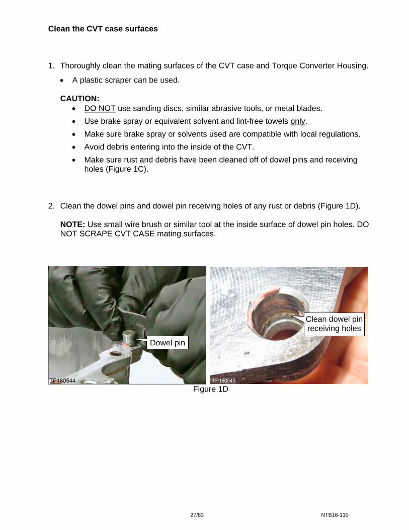
Clean the CVT case surfaces 1. Thoroughly clean the mating surfaces of the CVT case and Torque Converter Housing.
A plastic scraper can be used.
CAUTION: DO NOT use sanding discs, similar abrasive tools, or metal blades.
Use brake spray or equivalent solvent and lint-free towels only.
Make sure brake spray or solvents used are compatible with local regulations.
Avoid debris entering into the inside of the CVT.
Make sure rust and debris have been cleaned off of dowel pins and receiving holes (Figure 1C).
2. Clean the dowel pins and dowel pin receiving holes of any rust or debris (Figure 1D).
NOTE: Use small wire brush or similar tool at the inside surface of dowel pin holes. DO NOT SCRAPE CVT CASE mating surfaces.
Clean dowel pin receiving holes
Dowel pin
Figure 1D
27/83 NTB16-110
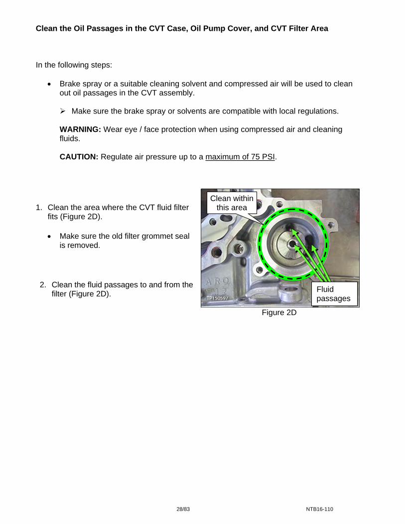
Clean the Oil Passages in the CVT Case, Oil Pump Cover, and CVT Filter Area In the following steps:
Brake spray or a suitable cleaning solvent and compressed air will be used to clean out oil passages in the CVT assembly.
Make sure the brake spray or solvents are compatible with local regulations.
WARNING: Wear eye / face protection when using compressed air and cleaning fluids.
CAUTION: Regulate air pressure up to a maximum of 75 PSI.
Figure 2D
Clean within this area 1. Clean the area where the CVT fluid filter
fits (Figure 2D).
Make sure the old filter grommet seal is removed.
2. Clean the fluid passages to and from the
filter (Figure 2D). Fluid passages
28/83 NTB16-110

3. Spray brake clean in all oil passages of the CVT case where shown in Figure 3D and
Figure 4D. 4. Apply compressed air in the same passages.
NOTE: Do not stand in front of the passages while using compressed air.
Figure 3D
Figure 4D
5. Temporarily install fluid filter cover.
Apply cleaner, and then 75 PSI maximum air pressure in these passages.
Air pressure comes out these passages.
29/83 NTB16-110
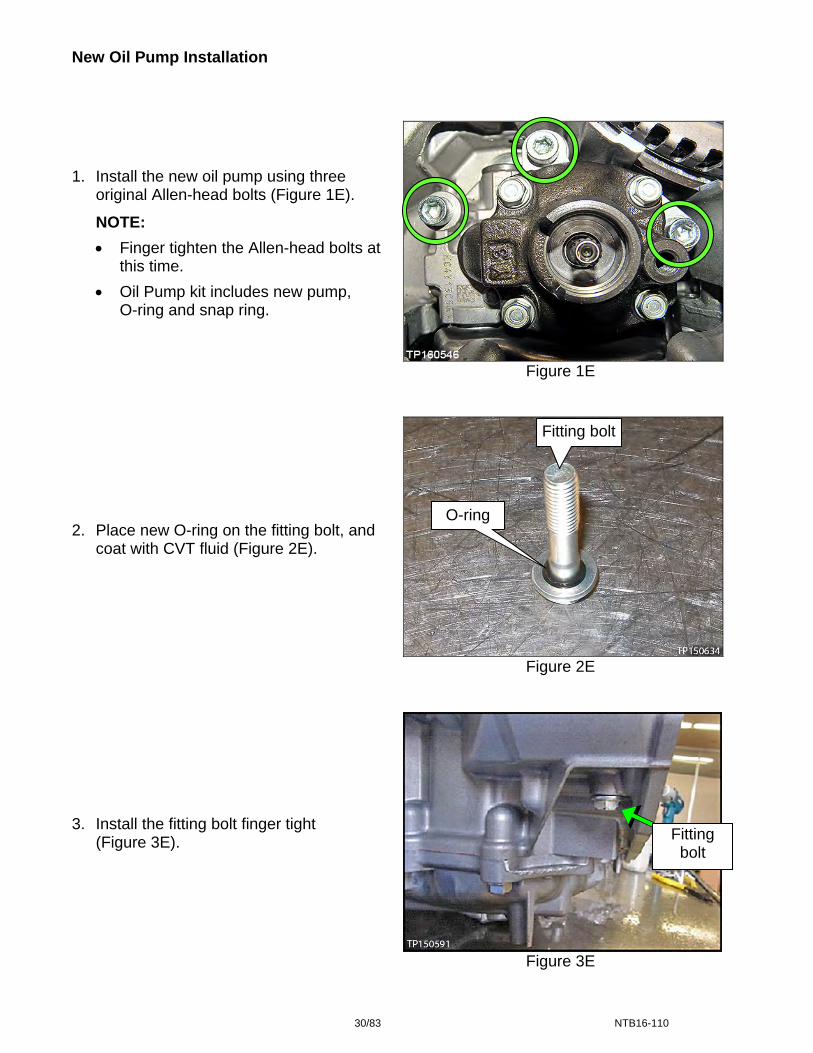
New Oil Pump Installation
1. Install the new oil pump using three original Allen-head bolts (Figure 1E).
NOTE:
Finger tighten the Allen-head bolts at this time.
Oil Pump kit includes new pump, O-ring and snap ring.
Figure 1E
Fitting bolt O-ring 2. Place new O-ring on the fitting bolt, and
coat with CVT fluid (Figure 2E). Figure 2E
3. Install the fitting bolt finger tight
(Figure 3E). Fitting bolt
Figure 3E
30/83 NTB16-110

4. Torque the three Allen head bolts and fitting bolt.
Allen head bolt torque: 17.6 – 20.6 N•m (1.79 – 2.1 kg-m, 13.0 – 15.2 ft-lb)
Fitting bolt torque: 26.0 – 30.0 N•m (2.65 – 3.06 kg-m, 19.2 – 22.1 ft-lb)
5. Install the new snap ring (Figure 4E).
Snap ring
Figure 4E
31/83 NTB16-110
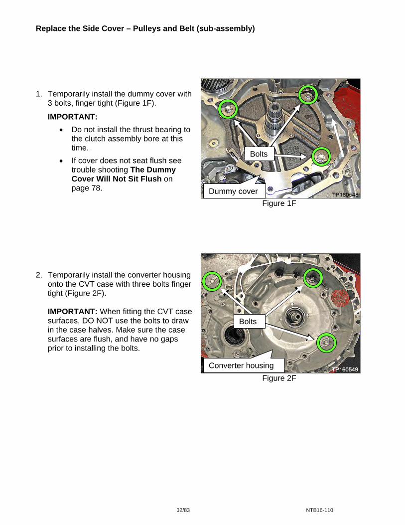
Replace the Side Cover – Pulleys and Belt (sub-assembly)
Figure 1F
Figure 2F
1. Temporarily install the dummy cover with 3 bolts, finger tight (Figure 1F).
IMPORTANT:
Do not install the thrust bearing to the clutch assembly bore at this time.
If cover does not seat flush see trouble shooting The Dummy Cover Will Not Sit Flush on page 78.
2. Temporarily install the converter housing onto the CVT case with three bolts finger tight (Figure 2F).
IMPORTANT: When fitting the CVT case surfaces, DO NOT use the bolts to draw in the case halves. Make sure the case surfaces are flush, and have no gaps prior to installing the bolts.
Dummy cover
Converter housing
Bolts
Bolts
32/83 NTB16-110
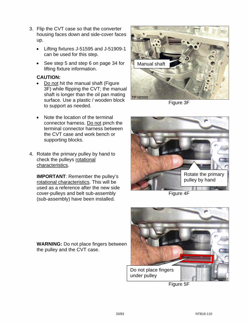
3. Flip the CVT case so that the converter housing faces down and side-cover facesup.
Lifting fixtures J-51595 and J-51909-1 can be used for this step.
See step 5 and step 6 on page 34 for lifting fixture information.
Manual shaft
CAUTION: Do not hit the manual shaft (Figure
3F) while flipping the CVT; the manual shaft is longer than the oil pan mating surface. Use a plastic / wooden block to support as needed.
Figure 3F
Note the location of the terminal
connector harness.
Do not pinch the terminal connector harness between the CVT case and work bench or supporting blocks.
4. Rotate the primary pulley by hand to check the pulleys rotational characteristics.
Rotate the primary pulley by hand
IMPORTANT: Remember the pulley’s rotational characteristics. This will be used as a reference after the new side cover-pulleys and belt sub-assembly (sub-assembly) have been installed.
Figure 4F
WARNING: Do not place fingers between the pulley and the CVT case.
Figure 5F
Do not place fingers under pulley
33/83 NTB16-110
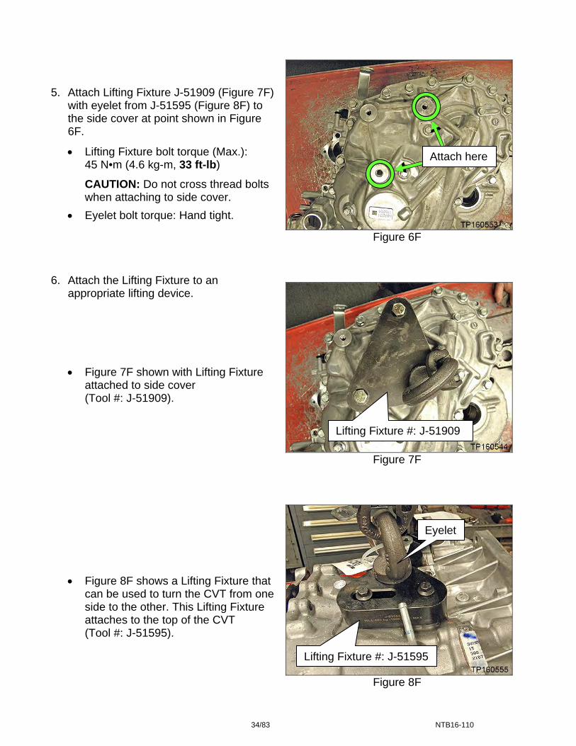
5. Attach Lifting Fixture J-51909 (Figure 7F)
with eyelet from J-51595 (Figure 8F) to the side cover at point shown in Figure 6F.
Figure 6F
Figure 7F
Figure 8F
Lifting Fixture bolt torque (Max.): 45 N•m (4.6 kg-m, 33 ft-lb)
Attach here
CAUTION: Do not cross thread bolts when attaching to side cover.
Eyelet bolt torque: Hand tight. 6. Attach the Lifting Fixture to an
appropriate lifting device.
Figure 7F shown with Lifting Fixture attached to side cover (Tool #: J-51909).
Lifting Fixture #: J-51909 Eyelet
Figure 8F shows a Lifting Fixture that can be used to turn the CVT from one side to the other. This Lifting Fixture attaches to the top of the CVT (Tool #: J-51595).
Lifting Fixture #: J-51595
34/83 NTB16-110
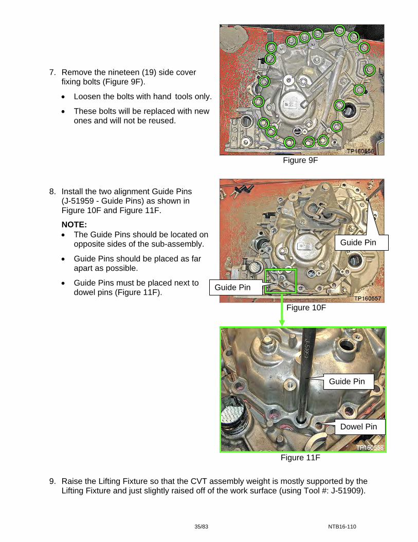
Figure 9F
Figure 10F
Figure 11F
9. Raise the Lifting Fixture so that the CVT assembly weight is mostly supported by the Lifting Fixture and just slightly raised off of the work surface (using Tool #: J-51909).
7. Remove the nineteen (19) side cover fixing bolts (Figure 9F).
Loosen the bolts with hand tools only.
These bolts will be replaced with new ones and will not be reused.
8. Install the two alignment Guide Pins (J-51959 - Guide Pins) as shown in Figure 10F and Figure 11F.
NOTE: The Guide Pins should be located on
opposite sides of the sub-assembly. Guide Pin
Guide Pins should be placed as far apart as possible.
Guide Pins must be placed next to dowel pins (Figure 11F).
Guide Pin
Guide Pin
Dowel Pin
35/83 NTB16-110
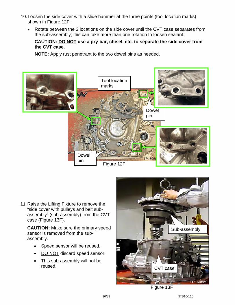
10. Loosen the side cover with a slide hammer at the three points (tool location marks) shown in Figure 12F.
Rotate between the 3 locations on the side cover until the CVT case separates from the sub-assembly; this can take more than one rotation to loosen sealant.
CAUTION: DO NOT use a pry-bar, chisel, etc. to separate the side cover from the CVT case.
NOTE: Apply rust penetrant to the two dowel pins as needed.
Figure 12F
Figure 13F
11. Raise the Lifting Fixture to remove the
“side cover with pulleys and belt sub-assembly” (sub-assembly) from the CVT case (Figure 13F).
CAUTION: Make sure the primary speed sensor is removed from the sub-assembly.
Speed sensor will be reused.
DO NOT discard speed sensor.
This sub-assembly will not be reused.
Sub-assembly
CVT case
Tool location marks
Dowel pin
Dowel pin
36/83 NTB16-110
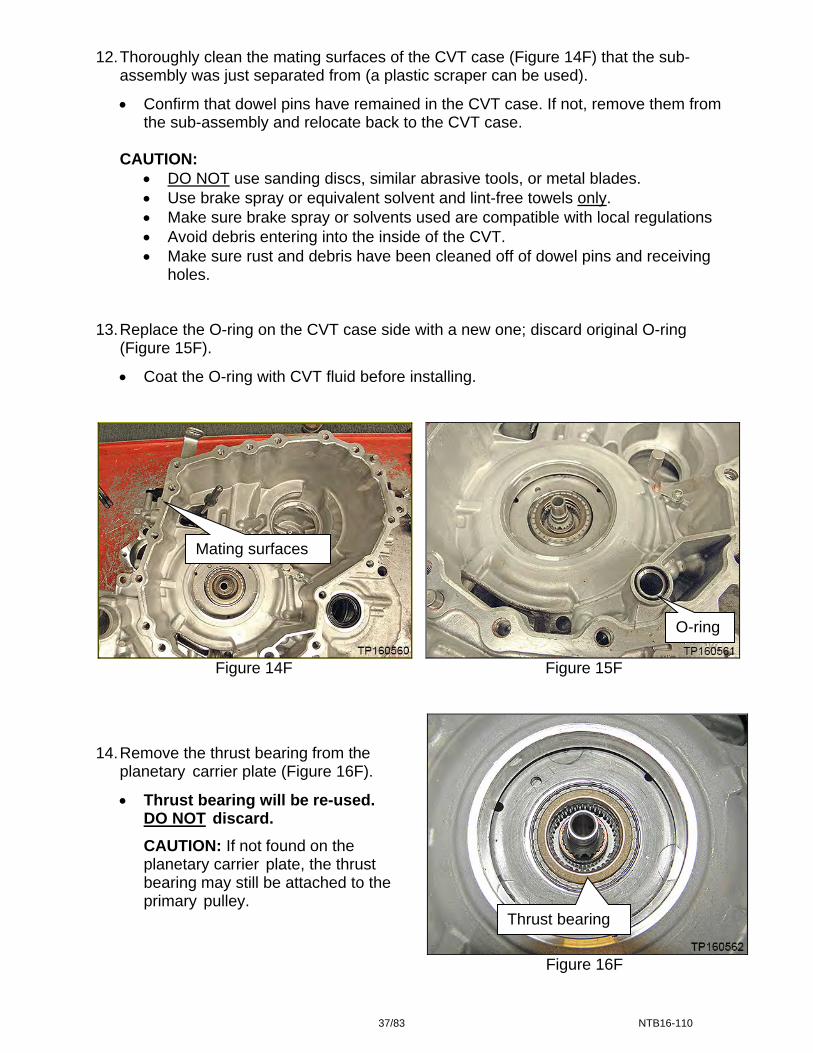
12. Thoroughly clean the mating surfaces of the CVT case (Figure 14F) that the sub-assembly was just separated from (a plastic scraper can be used).
Confirm that dowel pins have remained in the CVT case. If not, remove them from the sub-assembly and relocate back to the CVT case.
CAUTION:
DO NOT use sanding discs, similar abrasive tools, or metal blades. Use brake spray or equivalent solvent and lint-free towels only. Make sure brake spray or solvents used are compatible with local regulations Avoid debris entering into the inside of the CVT. Make sure rust and debris have been cleaned off of dowel pins and receiving
holes. 13. Replace the O-ring on the CVT case side with a new one; discard original O-ring
(Figure 15F).
Coat the O-ring with CVT fluid before installing.
Mating surfaces
O-ring
Figure 14F Figure 15F
14. Remove the thrust bearing from the planetary carrier plate (Figure 16F).
Thrust bearing will be re-used. DO NOT discard.
CAUTION: If not found on the planetary carrier plate, the thrust bearing may still be attached to the primary pulley.
Thrust bearing
Figure 16F
37/83 NTB16-110

15. Rotate the shift select lever counter clockwise to the “L” range position (Figure 17F), so that the park pawl is at its lowest position (Figure 18F).
Shift select lever
Figure 17F
Park pawl
Figure 18F
Lifting Fixture 16. Attach the Lifting Fixture to the new sub-
assembly.
CAUTION: Do not cross thread side cover holes when installing the Lifting Fixture. Always start bolts by hand.
Sub-assembly
Figure 19F
38/83 NTB16-110
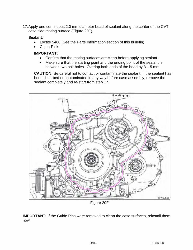
17. Apply one continuous 2.0 mm diameter bead of sealant along the center of the CVT
case side mating surface (Figure 20F).
Sealant: Loctite 5460 (See the Parts Information section of this bulletin) Color: Pink
IMPORTANT: Confirm that the mating surfaces are clean before applying sealant. Make sure that the starting point and the ending point of the sealant is
between two bolt holes. Overlap both ends of the bead by 3 – 5 mm.
CAUTION: Be careful not to contact or contaminate the sealant. If the sealant has been disturbed or contaminated in any way before case assembly, remove the sealant completely and re-start from step 17.
Figure 20F
IMPORTANT: If the Guide Pins were removed to clean the case surfaces, reinstall them now.
39/83 NTB16-110

18. Install the original thrust bearing on the primary pulley of the new sub-assembly part (Figure 21F).
CAUTION: The thrust bearing has two sides. Reference Figure 21F for bearing orientation.
Apply petroleum jelly or equivalent to the original thrust bearing to hold it in place on the primary pulley.
Primary pulley
Thrust bearing
Figure 21F
19. Coat the primary pulley bearing, secondary pulley gear teeth and the secondary bearing with CVT fluid prior to installation (Figure 22F).
CAUTION: Do NOT drip any CVT fluid onto the sealant. The following Figures are for reference only and may or may not have the sealant in place, or have the old sealant removed. Clean the surfaces and apply sealant when and where instructed.
Figure 22F
20. Route the Guide Pins into the appropriate CVT holes one at a time (the Guide Pins are different lengths).
Coat these surfaces with CVT fluid
40/83 NTB16-110
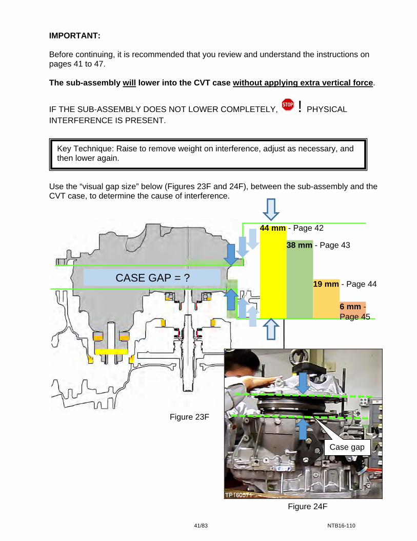
IMPORTANT: Before continuing, it is recommended that you review and understand the instructions on pages 41 to 47. The sub-assembly will lower into the CVT case without applying extra vertical force.
IF THE SUB-ASSEMBLY DOES NOT LOWER COMPLETELY, ! PHYSICAL INTERFERENCE IS PRESENT.
Key Technique: Raise to remove weight on interference, adjust as necessary, and then lower again.
Use the “visual gap size” below (Figures 23F and 24F), between the sub-assembly and the CVT case, to determine the cause of interference.
Figure 23F
Figure 24F
38 mm - Page 43
19 mm - Page 44
44 mm - Page 42
CASE GAP = ?
6 mm - Page 45
Case gap
41/83 NTB16-110
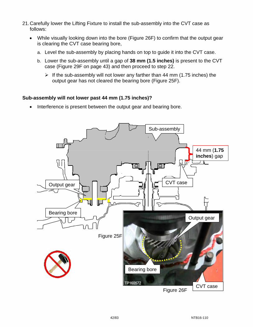
21. Carefully lower the Lifting Fixture to install the sub-assembly into the CVT case as
follows:
While visually looking down into the bore (Figure 26F) to confirm that the output gear is clearing the CVT case bearing bore,
a. Level the sub-assembly by placing hands on top to guide it into the CVT case.
b. Lower the sub-assembly until a gap of 38 mm (1.5 inches) is present to the CVT case (Figure 29F on page 43) and then proceed to step 22.
If the sub-assembly will not lower any farther than 44 mm (1.75 inches) the output gear has not cleared the bearing bore (Figure 25F).
Sub-assembly will not lower past 44 mm (1.75 inches)?
Interference is present between the output gear and bearing bore.
Sub-assembly
44 mm (1.75 inches) gap
CVT case Output gear
Bearing bore
Figure 25F
Figure 26F
Output gear
Bearing bore
CVT case
42/83 NTB16-110

CAUTION: In the following steps be careful not to contact or contaminate the sealant. If the sealant has been disturbed or contaminated in any way before case assembly, remove the sealant completely and re-start from step 17 on page 39. 22. Align the parking rod with the parking pawl as follows:
IMPORTANT: Perform step 22 while the sub-assembly has a 38 mm gap (1.5 inches) to the CVT case (Figure 29F).
c. Rotate the shift select lever clockwise on the side of the CVT to adjust the park rod
to the highest position.
d. Use a magnet, or similar tool, to align the park rod in the CVT case ( in Figure 28F) with the opening in the parking pawl ( in Figure 27F) in the side cover.
NOTE: If the parking rod is not located correctly it will keep the case from lowering. The following Figures are for reference only.
Figure 27F Figure 28F
Figure 29F
Side cover
Pocket magnet CVT case
Parking pawl
Parking rod
Sub-assembly
38 mm (1.5 inches) gap
CVT case
43/83 NTB16-110
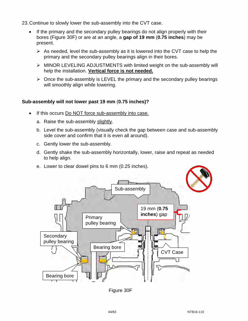
23. Continue to slowly lower the sub-assembly into the CVT case.
If the primary and the secondary pulley bearings do not align properly with their bores (Figure 30F) or are at an angle, a gap of 19 mm (0.75 inches) may be present.
As needed, level the sub-assembly as it is lowered into the CVT case to help the primary and the secondary pulley bearings align in their bores.
MINOR LEVELING ADJUSTMENTS with limited weight on the sub-assembly will help the installation. Vertical force is not needed.
Once the sub-assembly is LEVEL the primary and the secondary pulley bearings will smoothly align while lowering.
Sub-assembly will not lower past 19 mm (0.75 inches)?
If this occurs Do NOT force sub-assembly into case.
a. Raise the sub-assembly slightly.
b. Level the sub-assembly (visually check the gap between case and sub-assembly side cover and confirm that it is even all around).
c. Gently lower the sub-assembly.
d. Gently shake the sub-assembly horizontally, lower, raise and repeat as needed to help align.
e. Lower to clear dowel pins to 6 mm (0.25 inches).
Sub-assembly
19 mm (0.75 inches) gap
Figure 30F
Bearing bore
Primary pulley bearing
Secondary pulley bearing
Bearing bore CVT Case
44/83 NTB16-110
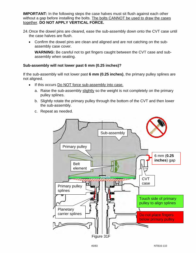
IMPORTANT: In the following steps the case halves must sit flush against each other without a gap before installing the bolts. The bolts CANNOT be used to draw the cases together. DO NOT APPLY VERTICAL FORCE. 24. Once the dowel pins are cleared, ease the sub-assembly down onto the CVT case until
the case halves are flush.
Confirm the dowel pins are clean and aligned and are not catching on the sub-assembly case cover.
WARNING: Be careful not to get fingers caught between the CVT case and sub-assembly when seating.
Sub-assembly will not lower past 6 mm (0.25 inches)? If the sub-assembly will not lower past 6 mm (0.25 inches), the primary pulley splines are not aligned.
If this occurs Do NOT force sub-assembly into case.
a. Raise the sub-assembly slightly so the weight is not completely on the primary pulley splines.
b. Slightly rotate the primary pulley through the bottom of the CVT and then lower the sub-assembly.
c. Repeat as needed.
Sub-assembly
Primary pulley
6 mm (0.25 inches) gap
Belt element
CVT case
Primary pulley splines
Touch side of primary pulley to align splines
Planetary carrier splines Do not place fingers
below primary pulley
Figure 31F
45/83 NTB16-110
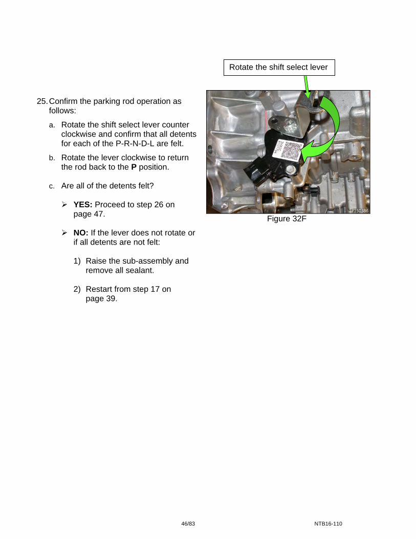
Figure 32F
Rotate the shift select lever 25. Confirm the parking rod operation as
follows:
a. Rotate the shift select lever counter clockwise and confirm that all detents for each of the P-R-N-D-L are felt.
b. Rotate the lever clockwise to return the rod back to the P position.
c. Are all of the detents felt?
YES: Proceed to step 26 on
page 47.
NO: If the lever does not rotate or if all detents are not felt:
1) Raise the sub-assembly and
remove all sealant.
2) Restart from step 17 on page 39.
46/83 NTB16-110

26. Install the new side cover bolts for sub-assembly to the CVT case (Figure 33F).
Torque the first eight (8) bolts marked as in the sequence numbered in Figure 33F below, and then torque the rest of the bolts in a clockwise manner.
Bolt torque: 45 N•m (4.6 kg-m, 33 ft-lb) 19 pieces.
Figure 33F
27. Confirm the rotational smoothness of the primary pulley as follows:
a. With clean hand, access the primary pulley from the bottom of the CVT to rotate.
b. Rotate the primary pulley by hand and confirm that the characteristic is the same as previously checked at step 4 (page 33), prior to removing the original sub-assembly.
c. Is the rotational characteristic worse than before the sub-assembly was replaced?
NO: The rotational characteristic is the same or better; proceed to step 28.
YES:
1) Remove the sub-assembly from the CVT case.
2) Wipe and clean the sealant completely from both the CVT case rim and side cover rim.
Refer to step 7 – 12 and 14 – 16 of “Replace Side Cover – Pulleys and Belt”.
3) Restart sub-assembly installation from Step 17 of “Replace Side Cover – Pulleys and Belt” on Page 39.
4) Return to step 27 and recheck rotational characteristic. 28. Remove the Lifting Fixture and Guide Pins.
8
5
1
3
6
24
7
Torque un-numbered bolts in clockwise pattern
47/83 NTB16-110
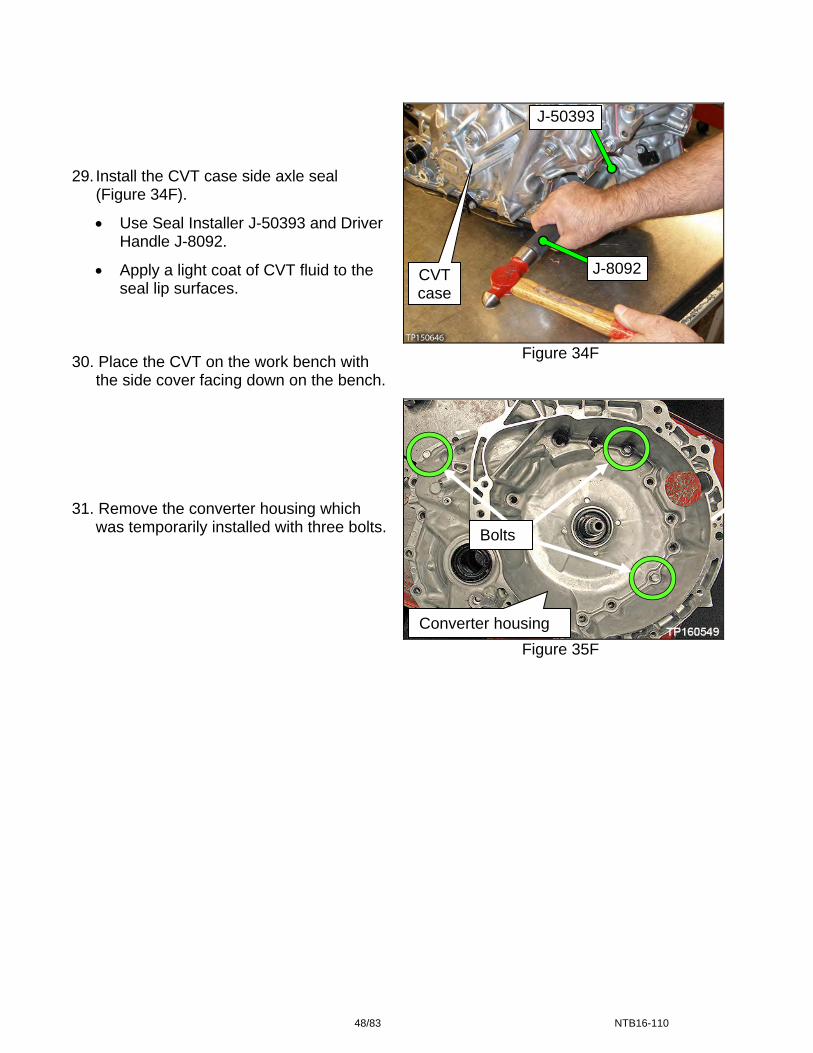
Figure 34F
Figure 35F
29. Install the CVT case side axle seal
(Figure 34F).
Use Seal Installer J-50393 and Driver Handle J-8092.
Apply a light coat of CVT fluid to the seal lip surfaces.
30. Place the CVT on the work bench with
the side cover facing down on the bench. 31. Remove the converter housing which
was temporarily installed with three bolts.
CVT case
Converter housing
J-50393
J-8092
Bolts
48/83 NTB16-110
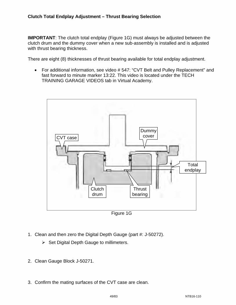
Clutch Total Endplay Adjustment – Thrust Bearing Selection IMPORTANT: The clutch total endplay (Figure 1G) must always be adjusted between the clutch drum and the dummy cover when a new sub-assembly is installed and is adjusted with thrust bearing thickness. There are eight (8) thicknesses of thrust bearing available for total endplay adjustment.
For additional information, see video # 547: “CVT Belt and Pulley Replacement” and fast forward to minute marker 13:22. This video is located under the TECH TRAINING GARAGE VIDEOS tab in Virtual Academy.
Dummy cover CVT case
Total endplay
Clutch drum
Thrust bearing
Figure 1G 1. Clean and then zero the Digital Depth Gauge (part #: J-50272).
Set Digital Depth Gauge to millimeters.
2. Clean Gauge Block J-50271. 3. Confirm the mating surfaces of the CVT case are clean.
49/83 NTB16-110

4. Calculate the average (D) clutch
assembly bore depth (Figure 2G) as follows:
IMPORTANT: Measurements are required from two opposite ends to obtain the average.
Figure 2G
Clutch assembly bore
a. Position the Gauge Block over the clutch assembly bore on the surface where the dummy cover seats (Figure 3G).
IMPORTANT: This surface is lower than the CVT case to torque converterhousing surface.
Gauge Block Dummy
cover seat Figure 3G
NOTE: The clutch assembly should sit 2-3 mm lower than the dummy cover seat (Figure 4G).
Dummy cover seat
b. Confirm the Gauge Block is not sitting
on the clutch assembly or against the input shaft.
NOTE: If the clutch assembly is sitting higher than the dummy cover surface, see trouble shooting The Dummy Cover Will Not Sit Flush on page 78. Clutch assembly
Figure 4G
50/83 NTB16-110

c. Position the Depth Gauge on the Gauge Block (Figure 5G).
Depth Gauge Datum level
NOTE: Make sure the Depth Gauge’s datum level is flush with the top of the Gauge Block.
d. Carefully slide the gauge down until it bottoms out on the bottom of the clutch assembly bore. Write this measurement as D1 (use millimeters).
Clutch assembly bore
NOTE: Do not measure from the clutch assembly bore shown in red (Figure 6G).
Gauge Block
Figure 5G
Do not measure from this raised step (highlighted in red).
Measure here; D2
Measure here; D1
Figure 6G
e. Measure this same distance on the opposite side (180 degrees) of the clutch assembly bore and write it as D2.
f. Using the formula below, calculate the average and write down the calculated value as D.
(D1 + D2)
D = -------------- Write the measurement for “D” here _____ mm
2
51/83 NTB16-110

5. Measure the average (H) dummy cover height (Figure 8G) as follows:
Clean surfaces Clean here
a. Clean the dummy cover surfaces that contact the CVT case and thrust bearing (Figure 7G).
Figure 7G
c. Position the Depth Gauge on the Gauge Block over an outer end of the dummy cover (Figure 8G).
NOTE: Make sure the Depth Gauge’s datum level is flush with the top of the Gauge Block.
d. Carefully slide the Depth Gauge down until it contacts the dummy cover surface that mates with the CVT case. Write this measurement as H1 (use millimeters).
e. Measure this same distance on the opposite side of the dummy cover and it write as H2 (Figure 8G).
CAUTION: Use brake spray (or equivalent) and lint-free towel only. Make sure the brake spray or solvents used are compatible with local regulations.
Clean here b. Place the dummy cover upside down
on a work bench, and place the Gauge Block onto the thrust bearing surface (Figure 8G).
Gauge Block
Figure 8G
f. Using the formula below, calculate the average and then write down the calculated value as H.
(H1 + H2) H =
2
(H1 + H2) H = --------------- Write the measurement for “H” here _____ mm 2
52/83 NTB16-110
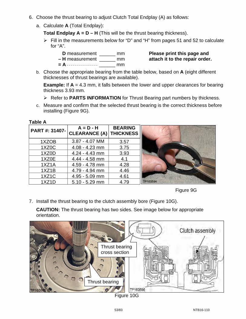
6. Choose the thrust bearing to adjust Clutch Total Endplay (A) as follows:
a. Calculate A (Total Endplay):
Total Endplay A = D – H (This will be the thrust bearing thickness).
Fill in the measurements below for “D” and “H” from pages 51 and 52 to calculate for “A”.
D measurement ______ mm Please print this page and – H measurement ______ mm attach it to the repair order. = A - - - - - - - - - - - - - - - - ______ mm
b. Choose the appropriate bearing from the table below, based on A (eight different thicknesses of thrust bearings are available).
Example: If A = 4.3 mm, it falls between the lower and upper clearances for bearing thickness 3.93 mm.
Refer to PARTS INFORMATION for Thrust Bearing part numbers by thickness.
c. Measure and confirm that the selected thrust bearing is the correct thickness before installing (Figure 9G).
Table A
PART #: 31407- A = D - H
CLEARANCE (A)BEARING
THICKNESS
1XZOB 3.87 - 4.07 MM 3.571XZ0C 4.08 - 4.23 mm 3.751XZ0D 4.24 - 4.43 mm 3.931XZ0E 4.44 - 4.58 mm 4.11XZ1A 4.59 - 4.78 mm 4.281XZ1B 4.79 - 4.94 mm 4.461XZ1C 4.95 - 5.09 mm 4.611XZ1D 5.10 - 5.29 mm 4.79
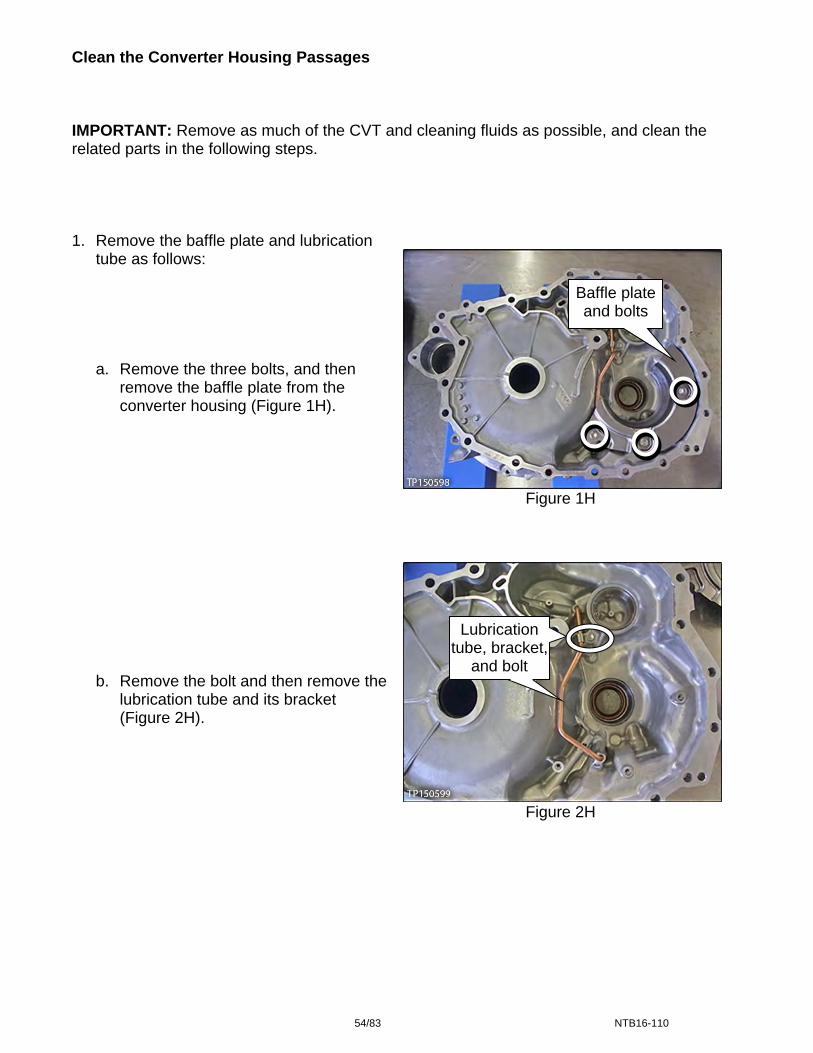
Figure 9G 7. Install the thrust bearing to the clutch assembly bore (Figure 10G).
CAUTION: The thrust bearing has two sides. See image below for appropriate orientation.
Thrust bearing cross section
Thrust bearing
Figure 10G
53/83 NTB16-110
Clean the Converter Housing Passages IMPORTANT: Remove as much of the CVT and cleaning fluids as possible, and clean the related parts in the following steps.
1. Remove the baffle plate and lubrication tube as follows:
Baffle plate and bolts
a. Remove the three bolts, and then remove the baffle plate from the converter housing (Figure 1H).
Figure 1H
Figure 2H
Lubrication tube and bracket
Lubrication tube, bracket,
and bolt
b. Remove the bolt and then remove the lubrication tube and its bracket (Figure 2H).
54/83 NTB16-110

2. Clean the oil passages of the converter housing, lubrication tube and dummy cover with brake spray (or equivalent) where shown in Figures 3H and 4H below.
NOTE: Do not stand in front of the passages shown while using compressed air.
Figure 3H
Figure 4H
3. Install the lubrication tube and bracket, and then the baffle plate with three bolts (Figure 5H).
Bolt torque: 5.9 N•m (0.6kg-m, 52 in-lb.)
Figure 5H
Air pressure comes out these
passages
Lubrication tube and bracket
Lubrication tube and bracket
Baffle plate and bolts
Apply cleaner, and then 75 PSI air pressure to
these passages
Apply cleaner, and then 75 PSI air pressure to this
passage
Air pressure comes out here
Apply 75 PSI maximum air pressure
in these passages
55/83 NTB16-110

CVT Reassembly
1. Install a new torque converter seal with Seal Installer J-50818 (Figure 1I).
Place the torque converter housing flat during installation. J-50818
Apply a light coat of CVT fluid to the seal lip surfaces.
The torque converter housing seal will be 0.5 mm (0.020 inches) below the bore’s surface when the seal installer bottoms out.
Figure 1I
Figure 2I
Figure 3I
J-50394
2. Install the torque converter housing side axle seal (Figure 2I).
Use Seal Installer J-50394 and Driver Handle J-8092.
J-8092
Apply a light coat of CVT fluid to the seal lip surfaces. Converter
housing Dummy
cover lathe cut seals
3. Apply petroleum jelly or equivalent to the
dummy cover’s lathe cut seals (Figure 3I) before installing the dummy cover to the CVT case.
56/83 NTB16-110

Figure 4I
Figure 5I
Figure 6I
Input shaft 4. Confirm that the input shaft’s lathe cut
seals are in the correct locations.
5. Install the dummy cover first, then baffle plate C, and then the related bolts finger tight (Figure 5I).
IMPORTANT: Visually check that the dummy cover is fully seated on the CVT case. If it is not, refer to Trouble Shooting pages 78 – 79.
Do not force the dummy cover into place.
Make sure the dummy cover is fully seated before installing the bolts.
Do not torque these bolts at this time. 6. Install baffle plate B and “L” bracket with
the related bolts finger tight (Figure 6I). 7. Torque the bolts from step 5 and 6 in the
following order:
a. Baffle plate B bolts: 5.9 N•m (0.6 kg- m, 52.2 in-lb.)
b. “L” bracket bolts: 25.5 N-m (2.6 kg-m, 19 ft- lb). Torque 1 and then 2 .
c. Dummy cover and baffle plate C bolts torque: 19.0 N•m (1.9 kg-m, 14 ft-lb.)
2
1 “L” bracket and bolts 1 2
Input shaft lathe cut
seals
Dummy cover, baffle plate C, and
bolts
Baffle plate B and bolts
57/83 NTB16-110
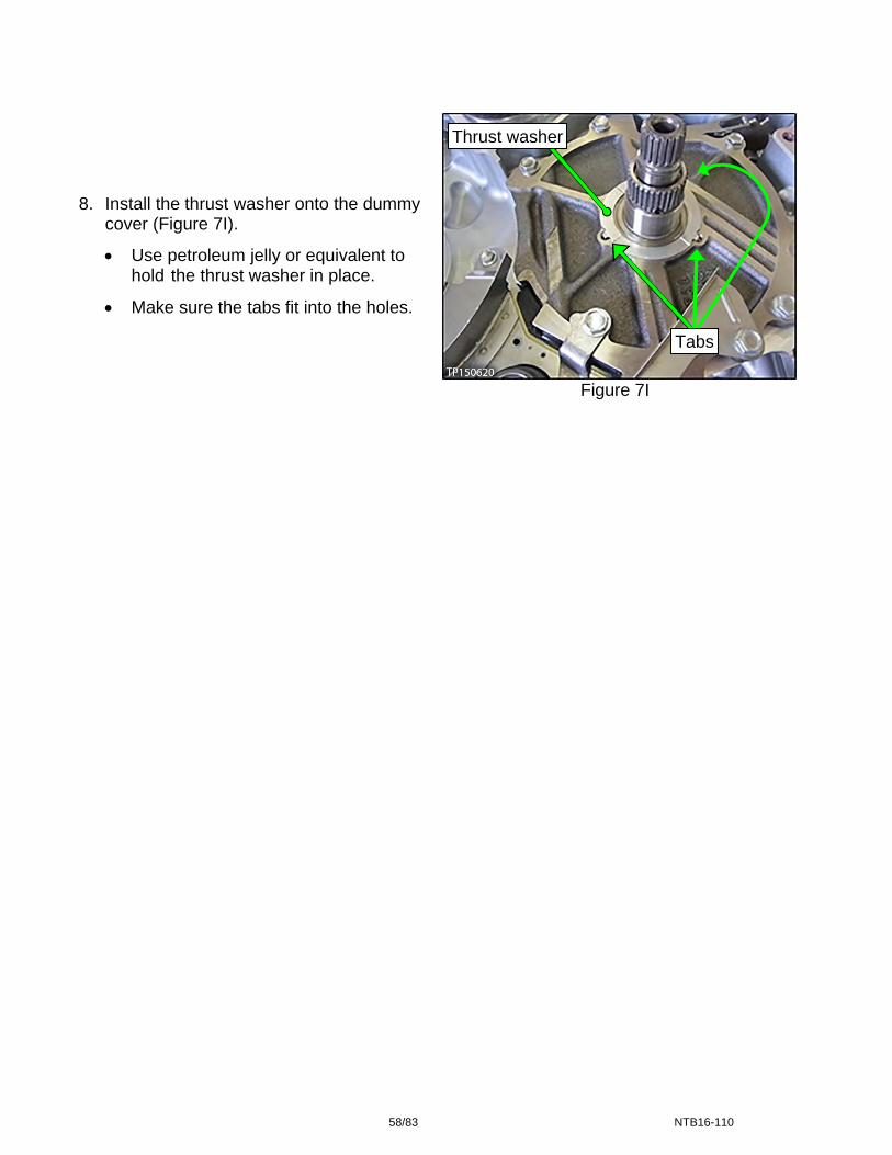
Figure 7I
Thrust washer
8. Install the thrust washer onto the dummy
cover (Figure 7I).
Use petroleum jelly or equivalent to hold the thrust washer in place.
Make sure the tabs fit into the holes.
Tabs
58/83 NTB16-110

Figure 8I
Figure 9I
Figure 10I
9. Install the drive sprocket, driven sprocket,
and chain as an assembly (Figure 8I).
Make sure the raised edge (wider edge) on the drive sprocket is facing up (Figure 9I).
a. Expand the snap ring with a suitable tool, and then push down on the driven sprocket until it bottoms out (Figure 10I).
b. Release the snap ring and then pull up on the driven sprocket until the snap ring locks into its groove.
NOTE: A click sound is heard when the snap ring locks in place.
Driven sprocket
Drive sprocket Chain Driven sprocket
Raised edge
Snap ring ends
59/83 NTB16-110

First baffle
plate nuts
10. Install baffle plate A with two nuts (Figure 11I).
Nut torque: 5.9 N•m (0.6 kg-m, 52.2 in-lb.)
Figure 11I
11. Install a new O-ring on the input shaft
(Figure 12I). O-ring
Apply CVT fluid to the O-ring and O-ring groove before installing.
Figure 12I 12. Install the differential assembly and the reduction gear assembly into the CVT case
(Figure 13I).
Thoroughly clean each assembly before installing.
Oil the bearings and gear teeth with CVT fluid before installing.
Reduction gear assembly Differential
assembly
Figure 13I
60/83 NTB16-110
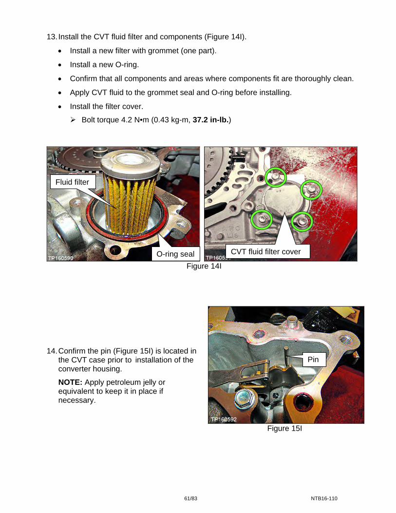
13. Install the CVT fluid filter and components (Figure 14I).
Install a new filter with grommet (one part).
Install a new O-ring.
Confirm that all components and areas where components fit are thoroughly clean.
Apply CVT fluid to the grommet seal and O-ring before installing.
Install the filter cover.
Bolt torque 4.2 N•m (0.43 kg-m, 37.2 in-lb.)
Figure 14I
Figure 15I
14. Confirm the pin (Figure 15I) is located in the CVT case prior to installation of the converter housing.
NOTE: Apply petroleum jelly or equivalent to keep it in place if necessary.
Pin
Fluid filter
CVT fluid filter cover O-ring seal
61/83 NTB16-110

15. Apply one continuous 2.0 mm (0.8 inches) diameter bead (Figure 16I) of pink colored
Loctite 5460 Sealant (see the Parts Information section of this bulletin).
Before sealant application, make sure the mating surfaces are clean from oil, dirt, old sealant, etc. (Figure 16I).
IMPORTANT: Have the converter housing ready for installation prior to applying the sealant.
NOTE: Start applying sealant where shown, making sure that the starting point and the
ending point are about the middle between the bolt holes. Overlap both ends of the bead by 3-5 mm (0.12-0.20 inches). Make sure to apply sealant around the center bolt hole.
Figure 16I
Also apply sealant around this bolt hole
62/83 NTB16-110
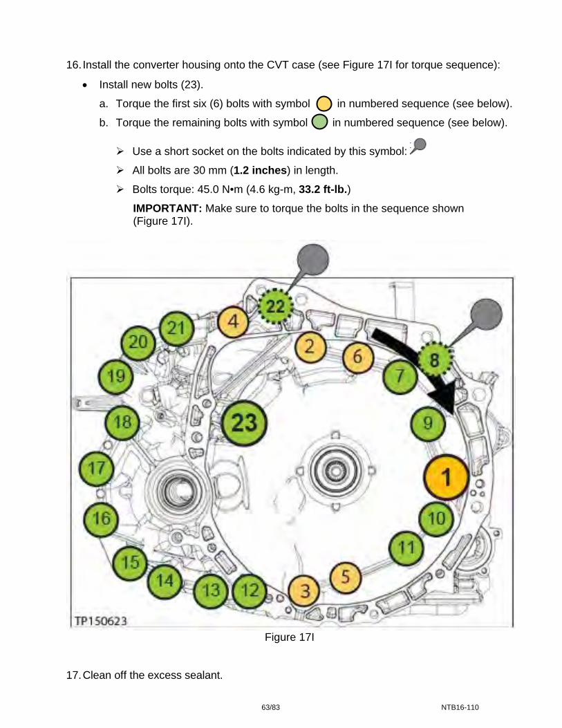
16. Install the converter housing onto the CVT case (see Figure 17I for torque sequence):
Install new bolts (23).
a. Torque the first six (6) bolts with symbol in numbered sequence (see below).
b. Torque the remaining bolts with symbol in numbered sequence (see below).
Use a short socket on the bolts indicated by this symbol:
All bolts are 30 mm (1.2 inches) in length.
Bolts torque: 45.0 N•m (4.6 kg-m, 33.2 ft-lb.)
IMPORTANT: Make sure to torque the bolts in the sequence shown (Figure 17I).
Figure 17I
17. Clean off the excess sealant.
63/83 NTB16-110

Control Valve (Valve Body) Strainer and Pan Installation IMPORTANT:
Installation steps in this bulletin may contain different style parts than what were originally installed in the CVT. Pay careful attention, REASSEMBLY MAY NOT BE IDENTICAL TO DISASSEMBLY.
Confirm that the QR label, control valve and CD part numbers all match before
installing the control valve (refer to NTB12-103).
For additional information, see video # 547: “CVT Belt and Pulley Replacement” and fast forward to minute marker 20:09. This video is located under the TECH TRAINING GARAGE VIDEOS tab in Virtual Academy.
CAUTION: Handle the valve body carefully.
NOTE: If an oil strainer bracket was removed, discard it. An oil strainer bracket (Figure 1J) will not be used with the new oil strainer. Oil strainer
bracket
Figure 1J
1. Install a new lip seal (Figure 2J).
Do NOT reuse the old lip seal.
Apply a small amount of petroleum jelly or equivalent to the lip seal to keep it in place on the CVT. Lip seal
Figure 2J
64/83 NTB16-110

Figure 3J
Figure 4J Figure 5J
2. Install the Control Valve with eleven (11) mounting bolts (Figure 3J).
IMPORTANT: Leave four (4) bolt holes blank at this step.
CAUTION: Make sure the wiring harness does not get pinched (see Figures 4J and 5J for correct routing).
54 mm (2.125 inches) long bolt ; 7 pieces
44 mm (1.73 inches) long bolt ; 2 pieces
25 mm long (1 inch) long bolt ; 2 pieces
CAUTION: The two 25 mm bolts are installed WITHOUT the strainer bracket.
Bolt torque: 7.9 N•m (0.81 kg-m, 70 in-lb.)
Correctly routed Incorrectly routed
25 mm bolts
44 mm bolts
65/83 NTB16-110
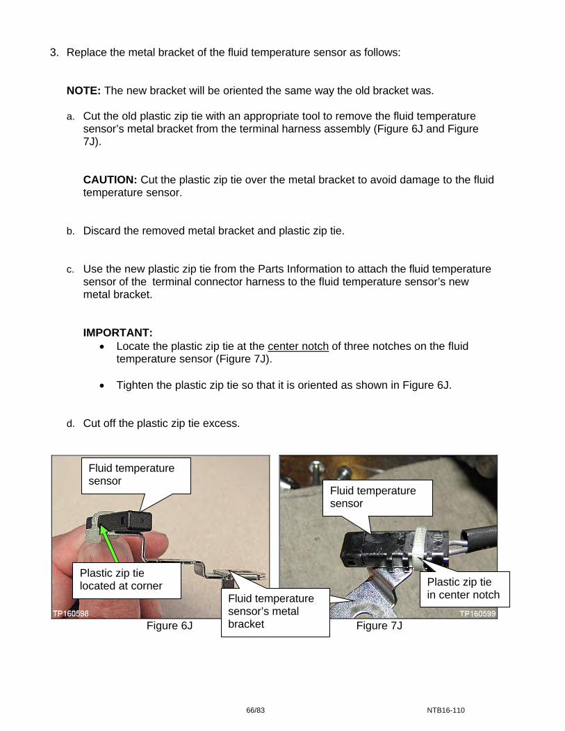
3. Replace the metal bracket of the fluid temperature sensor as follows:
NOTE: The new bracket will be oriented the same way the old bracket was.
a. Cut the old plastic zip tie with an appropriate tool to remove the fluid temperature sensor’s metal bracket from the terminal harness assembly (Figure 6J and Figure 7J).
CAUTION: Cut the plastic zip tie over the metal bracket to avoid damage to the fluid temperature sensor.
b. Discard the removed metal bracket and plastic zip tie.
c. Use the new plastic zip tie from the Parts Information to attach the fluid temperature sensor of the terminal connector harness to the fluid temperature sensor’s new metal bracket.
IMPORTANT: Locate the plastic zip tie at the center notch of three notches on the fluid
temperature sensor (Figure 7J).
Tighten the plastic zip tie so that it is oriented as shown in Figure 6J.
d. Cut off the plastic zip tie excess.
Fluid temperature sensor
Fluid temperature sensor
Plastic zip tie located at corner
Figure 6J Figure 7J
Plastic zip tie in center notch Temperatur
e sensor b k t
Fluid temperature sensor’s metal bracket
66/83 NTB16-110
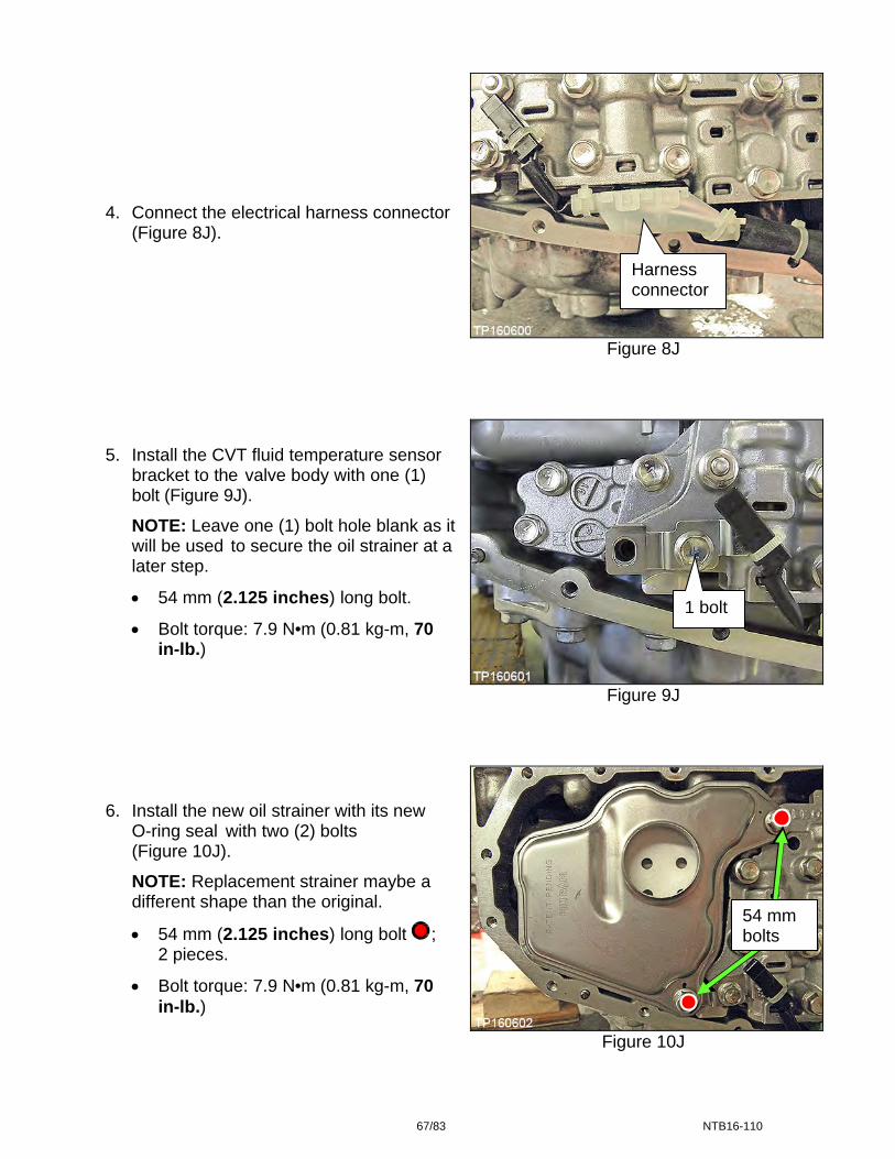
4. Connect the electrical harness connector
(Figure 8J).
Harness connector
Figure 8J
5. Install the CVT fluid temperature sensor
bracket to the valve body with one (1) bolt (Figure 9J).
NOTE: Leave one (1) bolt hole blank as itwill be used to secure the oil strainer at a later step.
54 mm (2.125 inches) long bolt. 1 bolt
Bolt torque: 7.9 N•m (0.81 kg-m, 70 in-lb.)
Figure 9J
6. Install the new oil strainer with its new
O-ring seal with two (2) bolts (Figure 10J).
Figure 10J
NOTE: Replacement strainer maybe a different shape than the original.
54 mm (2.125 inches) long bolt ; 2 pieces.
Bolt torque: 7.9 N•m (0.81 kg-m, 70 in-lb.)
54 mm bolts
67/83 NTB16-110
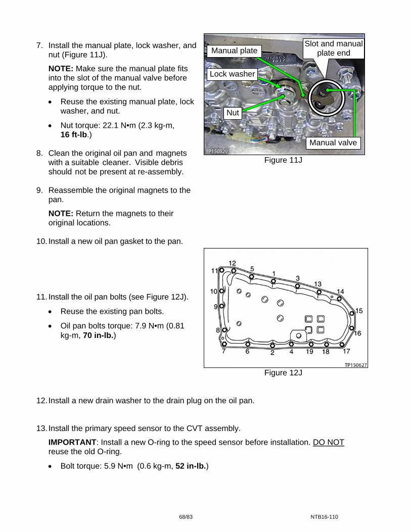
Figure 11J
Figure 12J
12. Install a new drain washer to the drain plug on the oil pan. 13. Install the primary speed sensor to the CVT assembly.
IMPORTANT: Install a new O-ring to the speed sensor before installation. DO NOT reuse the old O-ring.
Bolt torque: 5.9 N•m (0.6 kg-m, 52 in-lb.)
7. Install the manual plate, lock washer, and nut (Figure 11J).
NOTE: Make sure the manual plate fits into the slot of the manual valve before applying torque to the nut.
Reuse the existing manual plate, lock washer, and nut.
Nut torque: 22.1 N•m (2.3 kg-m, 16 ft-lb.)
8. Clean the original oil pan and magnets
with a suitable cleaner. Visible debris should not be present at re-assembly.
9. Reassemble the original magnets to the
pan.
NOTE: Return the magnets to their original locations.
10. Install a new oil pan gasket to the pan. 11. Install the oil pan bolts (see Figure 12J).
Reuse the existing pan bolts.
Oil pan bolts torque: 7.9 N•m (0.81 kg-m, 70 in-lb.)
Slot and manual plate end
Lock washer
Nut
Manual plate
Manual valve
68/83 NTB16-110
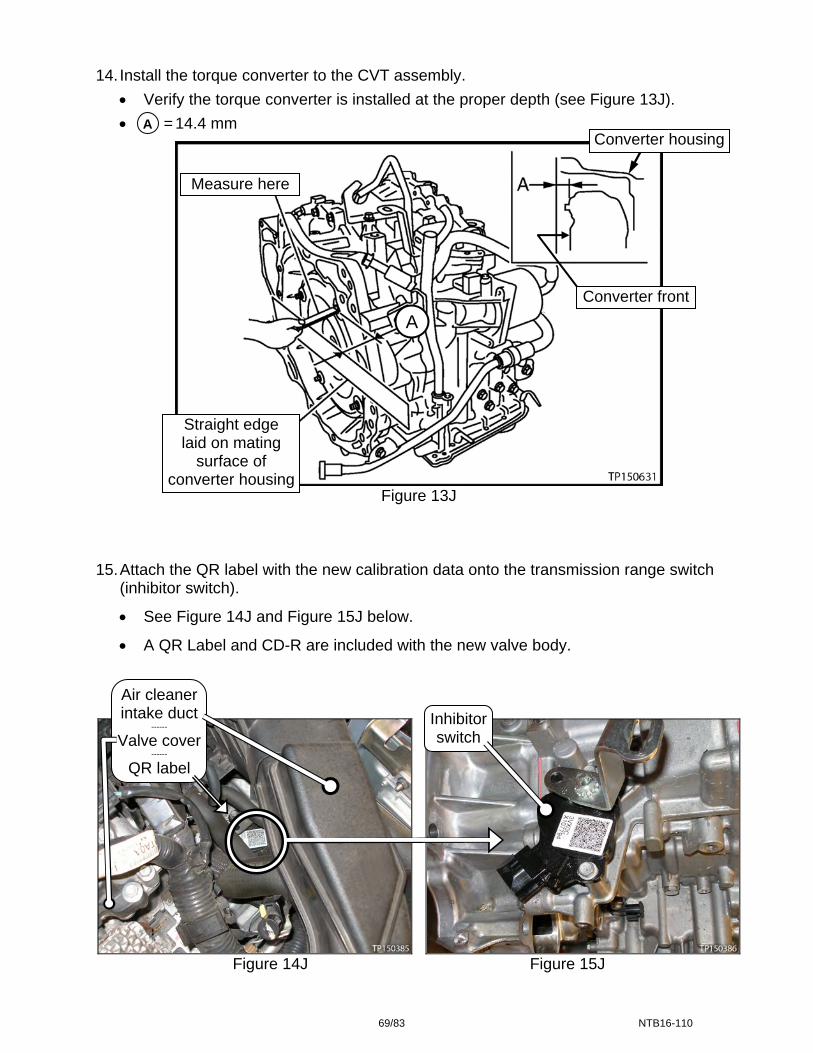
14. Install the torque converter to the CVT assembly.
Verify the torque converter is installed at the proper depth (see Figure 13J).
= 14.4 mm A
Converter housing
Measure here
Converter front
A
Straight edge laid on mating
surface of converter housing
Figure 13J 15. Attach the QR label with the new calibration data onto the transmission range switch
(inhibitor switch).
See Figure 14J and Figure 15J below.
A QR Label and CD-R are included with the new valve body.
Air cleaner intake duct Inhibitor
switch
Figure 14J Figure 15J
------
Valve cover ------
QR label
69/83 NTB16-110
Install the CVT Assembly 1. Install the CVT assembly in the vehicle.
Refer to the Electronic Service Manual (ESM), section TM-Transaxle & Transmission, for CVT installation.
2. Flush the CVT cooler.
IMPORTANT: A CVT Cooler flush is required. Refer to bulletin NTB15-013 to perform CVT Cooler flush.
3. Connect both battery cables, negative cable last. 4. Reset/reinitialize systems as needed.
Refer to the ESM, section PG – Power Supply & Ground Elements, for a listing of systems that require reset/initialization after reconnecting the 12V battery.
Look in the PG section index for ADDITIONAL SERVICE WHEN REMOVING BATTERY NEGATIVE TERMINAL.
This list often includes items such as radio, power windows, clock, sunroof, etc.
5. IMPORTANT: Install Write IP Characteristics to the TCM.
Refer to TM – Transaxle & Transmission / RE0F10D / BASIC INSPECTION, and perform ADDITIONAL SERVICE WHEN REPLACING TRANSAXLE ASSEMBLY.
6. Verify the CVT operates normally and no abnormal noises are heard during a test drive.
70/83 NTB16-110

TCM Reprogramming NOTE:
Most instructions for reprogramming with CONSULT-III plus (C-III plus) are displayed on the CONSULT PC screen.
If you are not familiar with the reprogramming procedure, click here. This will link
you to the "CONSULT- III plus Reprogramming" general procedure.
CAUTION:
Connect the GR8 to the vehicle battery, set to “power supply” mode. If the vehicle battery voltage drops below 12.0V or rises above 15.5V during reprogramming, the TCM may be damaged.
Be sure to turn OFF all vehicle electrical loads. If a vehicle electrical load remains ON, the TCM may be damaged.
Be sure to connect the AC Adapter. If the CONSULT PC battery voltage drops during reprogramming, the process will be interrupted and the TCM may be damaged.
Turn OFF all external Bluetooth® devices (e.g., cell phones, printers, etc.) within range of the CONSULT PC and the VI. If Bluetooth® signal waves are within range of the CONSULT PC during reprogramming, reprogramming may be interrupted and the TCM may be damaged.
71/83 NTB16-110

1. Connect the CONSULT PC to the vehicle to begin the reprogramming procedure. 2. Start C-III plus. 3. Wait for the plus VI to be recognized.
The serial number will display when the plus VI is recognized. 4. Select Re/programming, Configuration.
Step 3: plus VI is
recognized
Step 4
Figure 1K 5. Follow the on-screen instructions and navigate the C-III plus to the screen shown in
Figure 2K on the next page.
72/83 NTB16-110

6. When you get to the screen shown in Figure 2K, confirm this bulletin applies as follows.
A. Find the TCM Part Number and write it on the repair order.
NOTE: This is the current TCM Part Number (P/N).
Figure 2K
B. Compare the P/N you wrote down to the numbers in the Current TCM Part Number column in Table B below.
If there is a match, this bulletin applies. Continue with the reprogramming
procedure.
If there is not a match, reprogramming is not needed. Table B
MODEL MODEL YEAR
CURRENT TCM PART NUMBER BEFORE REPROGRAMMING: 31036 -
Altima (4-cyl engine only)
2015 9HM0A, 9HM0C, 9HM0D, 9HM0E
TRANSMISSION 6A: Current TCM P/N
31036 -
73/83 NTB16-110

7. Follow the on-screen instructions to navigate C-III plus and reprogram the TCM.
NOTE:
In some cases, more than one new P/N for reprogramming is available.
If more than one new P/N is available, the screen in Figure 3K displays.
Select and use the reprogramming option that does not have the message “Caution! Use ONLY with NTBXX-XXX”.
If you get this screen and it is blank (no reprogramming listed), it means there is no
reprogramming available for this vehicle.
TRANSMISSION
Figure 3K
74/83 NTB16-110

8. When the screen in Figure 4K displays, reprogramming is complete.
NOTE: If the screen in Figure 4K does not display (indicating that reprogramming did not complete), refer to the information on the next page.
9. Disconnect the battery charger from the vehicle. 10. Select Next.
Step 10
Figure 4K
NOTE:
In the next step (page 77) you will perform Erase All DTCs.
DTC erase is required before C-III plus will provide the final reprogramming confirmation report.
75/83 NTB16-110

TCM Recovery:
Do not disconnect plus VI or shut down C-III plus if reprogramming does not complete.
If reprogramming does not complete and the “!?” icon displays as shown in Figure 5K:
Check battery voltage (12.0–15.5 V).
Ignition is ON, engine OFF.
External Bluetooth® devices
are OFF.
Figure 5K
If reprogramming does not complete and the “X” icon displays as shown in Figure 6K:
All electrical loads are OFF.
Select retry and follow the
on screen instructions.
“Retry” may not go through on first attempt and can be selected more than once.
Check battery voltage (12.0 – 15.5 V).
CONSULT A/C adapter is
plugged in.
Ignition is ON, engine OFF.
Transmission is in Park.
All C-III plus / VI cables are securely connected.
All C-III plus updates are
installed. Figure 6K
Home, and restart Select the reprogram procedure from the beginning.
76/83 NTB16-110
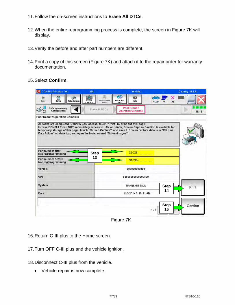
11. Follow the on-screen instructions to Erase All DTCs.
12. When the entire reprogramming process is complete, the screen in Figure 7K will display.
13. Verify the before and after part numbers are different.
14. Print a copy of this screen (Figure 7K) and attach it to the repair order for warranty documentation.
15. Select Confirm.
Figure 7K
16. Return C-III plus to the Home screen.
17. Turn OFF C-III plus and the vehicle ignition.
18. Disconnect C-III plus from the vehicle.
Vehicle repair is now complete.
Step 15
Step 31036 - _ _ _ _ _
13 31036 - _ _ _ _ _
Step TRANSMISSION
14
77/83 NTB16-110
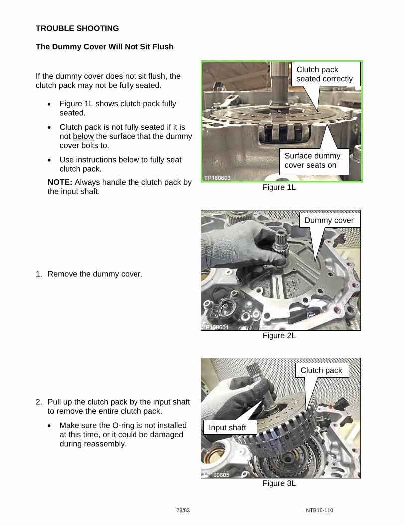
TROUBLE SHOOTING The Dummy Cover Will Not Sit Flush
Clutch pack seated correctly If the dummy cover does not sit flush, the
clutch pack may not be fully seated.
Figure 1L shows clutch pack fully seated.
Clutch pack is not fully seated if it is not below the surface that the dummy cover bolts to.
Surface dummy cover seats on
Use instructions below to fully seat clutch pack.
NOTE: Always handle the clutch pack by the input shaft. Figure 1L
Dummy cover 1. Remove the dummy cover.
Figure 2L
Clutch pack
2. Pull up the clutch pack by the input shaft
to remove the entire clutch pack.
Make sure the O-ring is not installed at this time, or it could be damaged during reassembly.
Input shaft
Figure 3L
78/83 NTB16-110

Clutch pack
Clutch pack layers 3. Gently using an appropriate tool align the
layers of the clutch pack.
Bottom of the clutch pack shown in Figure 4L.
Appropriate tool
Align layers
Figure 4L
4. Re-insert the entire clutch pack while holding the input shaft.
5. Gently jiggle the input shaft until the
clutch pack seats below case lip. Input shaft
6. If the clutch pack does not seat, rotate back and forth from the input shaft and jiggle.
7. If the clutch pack still does not seat,
repeat from step 2. Clutch pack
Figure 5L
79/83 NTB16-110
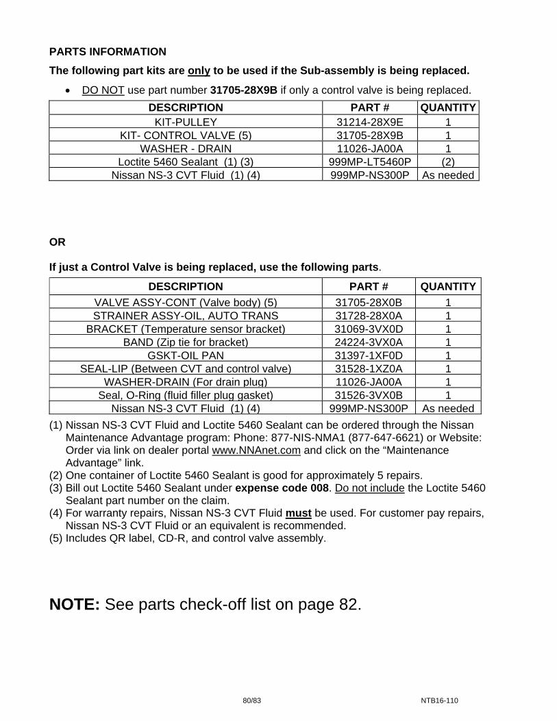
PARTS INFORMATION
The following part kits are only to be used if the Sub-assembly is being replaced.
DO NOT use part number 31705-28X9B if only a control valve is being replaced.
DESCRIPTION PART # QUANTITYKIT-PULLEY 31214-28X9E 1
KIT- CONTROL VALVE (5) 31705-28X9B 1WASHER - DRAIN 11026-JA00A 1
Loctite 5460 Sealant (1) (3) 999MP-LT5460P (2)Nissan NS-3 CVT Fluid (1) (4) 999MP-NS300P As needed
OR If just a Control Valve is being replaced, use the following parts.
DESCRIPTION PART # QUANTITY
VALVE ASSY-CONT (Valve body) (5) 31705-28X0B 1STRAINER ASSY-OIL, AUTO TRANS 31728-28X0A 1
BRACKET (Temperature sensor bracket) 31069-3VX0D 1BAND (Zip tie for bracket) 24224-3VX0A 1
GSKT-OIL PAN 31397-1XF0D 1SEAL-LIP (Between CVT and control valve) 31528-1XZ0A 1
WASHER-DRAIN (For drain plug) 11026-JA00A 1Seal, O-Ring (fluid filler plug gasket) 31526-3VX0B 1
Nissan NS-3 CVT Fluid (1) (4) 999MP-NS300P As needed
(1) Nissan NS-3 CVT Fluid and Loctite 5460 Sealant can be ordered through the Nissan Maintenance Advantage program: Phone: 877-NIS-NMA1 (877-647-6621) or Website: Order via link on dealer portal www.NNAnet.com and click on the “Maintenance Advantage” link.
(2) One container of Loctite 5460 Sealant is good for approximately 5 repairs. (3) Bill out Loctite 5460 Sealant under expense code 008. Do not include the Loctite 5460
Sealant part number on the claim. (4) For warranty repairs, Nissan NS-3 CVT Fluid must be used. For customer pay repairs,
Nissan NS-3 CVT Fluid or an equivalent is recommended. (5) Includes QR label, CD-R, and control valve assembly.
NOTE: See parts check-off list on page 82.
80/83 NTB16-110

CLAIMS INFORMATION
Submit a Primary Part (PP) type line claim using the following claims coding: OPERATION PFP OP CODE SYM DIAG FRT
CVT R&R
(1)
JD01AA
ZE 32
(2) JD023A
Inspect CVT Belt, Belt = NG (Includes control valve R&I)
JX36AA 2.2
Replace CVT Sub-assembly JX45AA 2.9Reprogram TCM JE99AA (2)
(1) Reference the electronic Parts Catalog (FAST or equivalent) and use the CVT assembly part number for the vehicle being repaired as the Primary Failed Part.
(2) Reference the current Nissan Warranty Flat Rate Manual and use the indicated Flat Rate Time. NOTE: FRT allows adequate time to access DTC codes. No other diagnostic procedures subsequently required. Do NOT claim any diagnostic OP Codes with this claim.
EXPENSE CODE
EXPENSE CODE DESCRIPTION MAX AMOUNT 008 5460 Sealant $12.46
OR
Submit a Primary Part (PP) type line claim using the following claims coding: OPERATION PFP OP CODE SYM DIAG FRT
Inspect CVT Belt, Belt = OK(1)
JX37AAZE 32
0.3Replace Valve Body JD48AA (2)
Reprogram TCM JE99AA (2)
(1) Reference the Parts Information Table and use the applicable Control Valve Assembly Part Number (31705-*****) as the Primary Failed Part.
(2) Reference the current Nissan Warranty Flat Rate Manual and use the indicated Flat Rate Time. NOTE: FRT allows adequate time to access DTC codes. No other diagnostic procedures subsequently required. Do NOT claim any diagnostic OP Codes with this claim.
81/83 NTB16-110
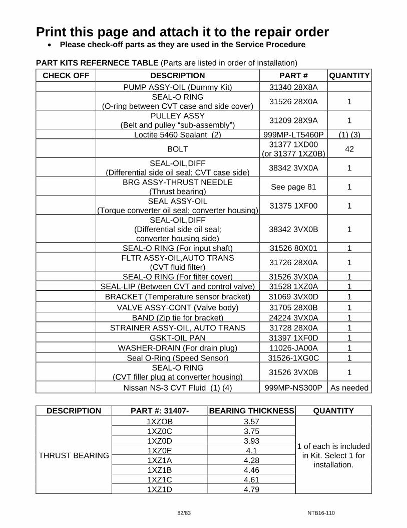
Print this page and attach it to the repair order Please check-off parts as they are used in the Service Procedure
PART KITS REFERNECE TABLE (Parts are listed in order of installation)
CHECK OFF DESCRIPTION PART # QUANTITY
PUMP ASSY-OIL (Dummy Kit) 31340 28X8A
SEAL-O RING (O-ring between CVT case and side cover)
31526 28X0A 1
PULLEY ASSY
(Belt and pulley “sub-assembly”)31209 28X9A 1
Loctite 5460 Sealant (2) 999MP-LT5460P (1) (3)
BOLT 31377 1XD00
(or 31377 1XZ0B) 42
SEAL-OIL,DIFF (Differential side oil seal; CVT case side)
38342 3VX0A 1
BRG ASSY-THRUST NEEDLE
(Thrust bearing)See page 81 1
SEAL ASSY-OIL (Torque converter oil seal; converter housing)
31375 1XF00 1
SEAL-OIL,DIFF (Differential side oil seal; converter housing side)
38342 3VX0B 1
SEAL-O RING (For input shaft) 31526 80X01 1
FLTR ASSY-OIL,AUTO TRANS
(CVT fluid filter)31726 28X0A 1
SEAL-O RING (For filter cover) 31526 3VX0A 1 SEAL-LIP (Between CVT and control valve) 31528 1XZ0A 1 BRACKET (Temperature sensor bracket) 31069 3VX0D 1 VALVE ASSY-CONT (Valve body) 31705 28X0B 1 BAND (Zip tie for bracket) 24224 3VX0A 1 STRAINER ASSY-OIL, AUTO TRANS 31728 28X0A 1 GSKT-OIL PAN 31397 1XF0D 1 WASHER-DRAIN (For drain plug) 11026-JA00A 1 Seal O-Ring (Speed Sensor) 31526-1XG0C 1
SEAL-O RING
(CVT filler plug at converter housing)31526 3VX0B 1
Nissan NS-3 CVT Fluid (1) (4) 999MP-NS300P As needed
DESCRIPTION PART #: 31407- BEARING THICKNESS QUANTITY
THRUST BEARING
1XZOB 3.57
1 of each is included in Kit. Select 1 for
installation.
1XZ0C 3.751XZ0D 3.931XZ0E 4.11XZ1A 4.281XZ1B 4.461XZ1C 4.611XZ1D 4.79
82/83 NTB16-110
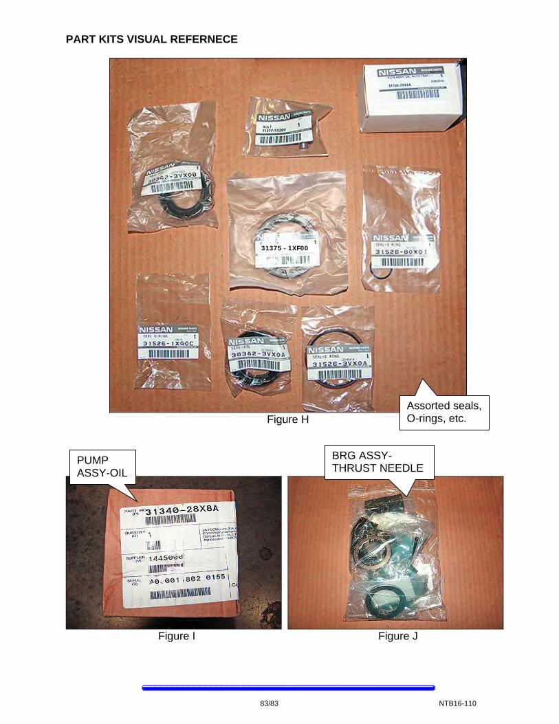
PART KITS VISUAL REFERNECE
31375 - 1XF00
Assorted seals, O-rings, etc. Figure H
83/83 NTB16-110
BRG ASSY-THRUST NEEDLE
PUMP ASSY-OIL
Figure I Figure J