ViPER Video Annotation and Performance Evaluation viper-toolkit.sf.net.

ViperChrysler Group LLC
OWNER ’S MANUAL
2014
20
14
Vip
er
14ZD-126-AA First Edition Printed in U.S.A.
VEHICLES SOLD IN CANADAWith respect to any Vehicles Sold in Canada, the nameChrysler Group LLC shall be deemed to be deleted and thename Chrysler Canada Inc. used in substitution therefore.
DRIVING AND ALCOHOLDrunken driving is one of the most frequent causes ofaccidents.
Your driving ability can be seriously impaired with bloodalcohol levels far below the legal minimum. If you aredrinking, don’t drive. Ride with a designated non-drinkingdriver, call a cab, a friend, or use public transportation.
WARNING!
Driving after drinking can lead to an accident. Yourperceptions are less sharp, your reflexes are slower,and your judgment is impaired when you have beendrinking. Never drink and then drive.
This manual illustrates and describes the operation offeatures and equipment that are either standard oroptional on this vehicle. This manual may also include adescription of features and equipment that are no longeravailable or were not ordered on this vehicle. Pleasedisregard any features and equipment described in thismanual that are not on this vehicle.
Chrysler Group LLC reserves the right to make changesin design and specifications, and/or make additions to orimprovements to its products without imposing anyobligation upon itself to install them on products previ-ously manufactured.
Copyright © 2013 Chrysler Group LLC
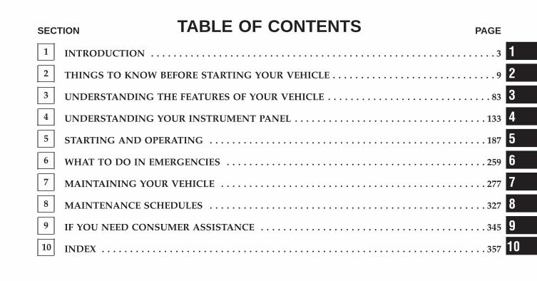
TABLE OF CONTENTSSECTION PAGE
1 INTRODUCTION . . . . . . . . . . . . . . . . . . . . . . . . . . . . . . . . . . . . . . . . . . . . . . . . . . . . . . . . . . . . . 3
2 THINGS TO KNOW BEFORE STARTING YOUR VEHICLE . . . . . . . . . . . . . . . . . . . . . . . . . . . . . 9
3 UNDERSTANDING THE FEATURES OF YOUR VEHICLE . . . . . . . . . . . . . . . . . . . . . . . . . . . . . 83
4 UNDERSTANDING YOUR INSTRUMENT PANEL . . . . . . . . . . . . . . . . . . . . . . . . . . . . . . . . . . 133
5 STARTING AND OPERATING . . . . . . . . . . . . . . . . . . . . . . . . . . . . . . . . . . . . . . . . . . . . . . . . . 187
6 WHAT TO DO IN EMERGENCIES . . . . . . . . . . . . . . . . . . . . . . . . . . . . . . . . . . . . . . . . . . . . . . 259
7 MAINTAINING YOUR VEHICLE . . . . . . . . . . . . . . . . . . . . . . . . . . . . . . . . . . . . . . . . . . . . . . . 277
8 MAINTENANCE SCHEDULES . . . . . . . . . . . . . . . . . . . . . . . . . . . . . . . . . . . . . . . . . . . . . . . . . 327
9 IF YOU NEED CONSUMER ASSISTANCE . . . . . . . . . . . . . . . . . . . . . . . . . . . . . . . . . . . . . . . . 345
10 INDEX . . . . . . . . . . . . . . . . . . . . . . . . . . . . . . . . . . . . . . . . . . . . . . . . . . . . . . . . . . . . . . . . . . . . 357
1
2
3
4
5
6
7
8
9
10

INTRODUCTION
CONTENTS� INTRODUCTION . . . . . . . . . . . . . . . . . . . . . . . .4
� HOW TO USE THIS MANUAL . . . . . . . . . . . . . .4
� WARNINGS AND CAUTIONS . . . . . . . . . . . . . .6
� VEHICLE IDENTIFICATION NUMBER . . . . . . . .6
� VEHICLE MODIFICATIONS/ALTERATIONS . . . .7
1
INTRODUCTION
Congratulations on selecting your new Chrysler GroupLLC vehicle. Be assured that it represents precisionworkmanship, distinctive styling, and high quality - allessentials that are traditional to our vehicles.
This Owner’s Manual has been prepared with the assis-tance of service and engineering specialists to acquaintyou with the operation and maintenance of your vehicle.It is supplemented by Warranty Information, and variouscustomer-oriented documents. Please take the time toread these publications carefully. Following the instruc-tions and recommendations in this manual will helpassure safe and enjoyable operation of your vehicle.
NOTE: After reviewing the owner information, itshould be stored in the vehicle for convenient referenc-ing and remain with the vehicle when sold.
When it comes to service, remember that your authorizeddealer knows your vehicle best, has factory-trained tech-nicians and genuine parts, and cares about your satisfac-tion.
HOW TO USE THIS MANUAL
Consult the Table of Contents to determine which sectioncontains the information you desire.
Since the specification of your vehicle depends on theitems of equipment ordered, certain descriptions andillustrations may differ from your vehicle’s equipment.
The detailed index at the back of this Owner’s Manualcontains a complete listing of all subjects.
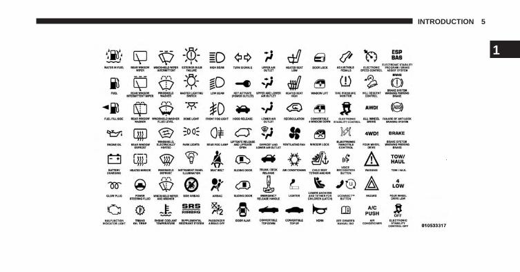
Consult the following table for a description of thesymbols that may be used on your vehicle or throughoutthis Owner’s Manual:
4 INTRODUCTION
1
INTRODUCTION 5
WARNINGS AND CAUTIONS
This Owners Manual contains WARNINGS against op-erating procedures that could result in a collision orbodily injury. It also contains CAUTIONS against proce-dures that could result in damage to your vehicle. If youdo not read this entire Owners Manual, you may missimportant information. Observe all Warnings and Cau-tions.
VEHICLE IDENTIFICATION NUMBER
The Vehicle Identification Number (VIN) is on the leftfront corner of the instrument panel and is visible fromoutside the vehicle through the windshield. This numberalso appears on the top surface of the right-hand sidetunnel frame rail near the center of the vehicle, theoutboard facing surface of the right-hand side B-Pillarframe rail, as well as the Automobile Information Disclo-sure Label affixed to a window on your vehicle, thevehicle registration, and the title.
6 INTRODUCTION
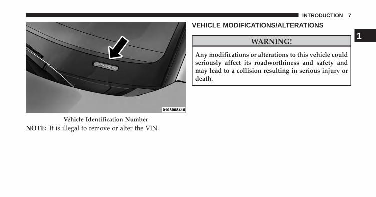
NOTE: It is illegal to remove or alter the VIN.
VEHICLE MODIFICATIONS/ALTERATIONS
WARNING!
Any modifications or alterations to this vehicle couldseriously affect its roadworthiness and safety andmay lead to a collision resulting in serious injury ordeath.
Vehicle Identification Number
1
INTRODUCTION 7

THINGS TO KNOW BEFORE STARTING YOUR VEHICLE
CONTENTS� A WORD ABOUT YOUR KEYS . . . . . . . . . . . . .12
▫ Keyless Ignition Node (KIN) . . . . . . . . . . . . . .12
▫ Key Fob . . . . . . . . . . . . . . . . . . . . . . . . . . . . .13
▫ Ignition Or Accessory On Message . . . . . . . . . .15
� SENTRY KEY® . . . . . . . . . . . . . . . . . . . . . . . . .16
▫ Replacement Keys . . . . . . . . . . . . . . . . . . . . .17
▫ Customer Key Programming . . . . . . . . . . . . . .18
▫ General Information . . . . . . . . . . . . . . . . . . . .18
� VEHICLE SECURITY ALARM SYSTEM . . . . . . .18
▫ Rearming of the System . . . . . . . . . . . . . . . . . .18
▫ To Arm The System. . . . . . . . . . . . . . . . . . . . .18
▫ To Disarm The System . . . . . . . . . . . . . . . . . . .19
� ILLUMINATED ENTRY . . . . . . . . . . . . . . . . . . .20
� REMOTE KEYLESS ENTRY (RKE) . . . . . . . . . . .21
▫ To Unlock The Doors. . . . . . . . . . . . . . . . . . . .22
▫ To Lock The Doors . . . . . . . . . . . . . . . . . . . . .22
▫ To Unlatch The Liftgate . . . . . . . . . . . . . . . . . .23
▫ Using The Panic Alarm . . . . . . . . . . . . . . . . . .23
▫ Programming Additional Transmitters . . . . . . .23
▫ Transmitter Battery Replacement . . . . . . . . . . .23
2
▫ General Information . . . . . . . . . . . . . . . . . . . .26
� DOOR LOCKS . . . . . . . . . . . . . . . . . . . . . . . . .27
▫ Power Door Locks . . . . . . . . . . . . . . . . . . . . .27
� WINDOWS . . . . . . . . . . . . . . . . . . . . . . . . . . .30
▫ Power Windows . . . . . . . . . . . . . . . . . . . . . . .30
▫ Auto-Down Feature . . . . . . . . . . . . . . . . . . . .31
▫ AUTO-Up Feature With Anti-PinchProtection — If Equipped . . . . . . . . . . . . . . . .31
▫ Reset Auto-Up . . . . . . . . . . . . . . . . . . . . . . . .32
� LIFTGATE . . . . . . . . . . . . . . . . . . . . . . . . . . . .32
� OCCUPANT RESTRAINTS . . . . . . . . . . . . . . . .34
▫ Lap/Shoulder Belts . . . . . . . . . . . . . . . . . . . .36
▫ Lap/Shoulder Belt Operating Instructions . . . .39
▫ Lap/Shoulder Belt Untwisting Procedure . . . . .43
▫ Automatic Locking Retractor Mode (ALR) —If Equipped . . . . . . . . . . . . . . . . . . . . . . . . . .43
▫ Seat Belt Pretensioners . . . . . . . . . . . . . . . . . .44
▫ Enhanced Seat Belt Use Reminder System(BeltAlert®) . . . . . . . . . . . . . . . . . . . . . . . . . .45
▫ Seat Belts and Pregnant Women . . . . . . . . . . . .46
▫ Seat Belt Extender . . . . . . . . . . . . . . . . . . . . .46
▫ Supplemental Restraint System (SRS) —Air Bags . . . . . . . . . . . . . . . . . . . . . . . . . . . .46
▫ Advanced Front Air Bag Features . . . . . . . . . . .51
▫ Air Bag Deployment Sensors And Controls . . . .51
▫ Child Restraints . . . . . . . . . . . . . . . . . . . . . . .68
� BREAK-IN RECOMMENDATIONS . . . . . . . . . . .78
10 THINGS TO KNOW BEFORE STARTING YOUR VEHICLE
� SAFETY TIPS . . . . . . . . . . . . . . . . . . . . . . . . . .78
▫ Transporting Passengers. . . . . . . . . . . . . . . . . .78
▫ Exhaust Gas . . . . . . . . . . . . . . . . . . . . . . . . .79
▫ Safety Checks You Should Make Inside TheVehicle . . . . . . . . . . . . . . . . . . . . . . . . . . . . .80
▫ Periodic Safety Checks You Should MakeOutside The Vehicle . . . . . . . . . . . . . . . . . . . .81 2
THINGS TO KNOW BEFORE STARTING YOUR VEHICLE 11
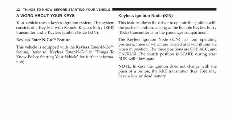
A WORD ABOUT YOUR KEYS
Your vehicle uses a keyless ignition system. This systemconsists of a Key Fob with Remote Keyless Entry (RKE)transmitter and a Keyless Ignition Node (KIN).
Keyless Enter-N-Go™ Feature
This vehicle is equipped with the Keyless Enter-N-Go™feature, (refer to �Keyless Enter-N-Go� in �Things ToKnow Before Starting Your Vehicle� for further informa-tion).
Keyless Ignition Node (KIN)
This feature allows the driver to operate the ignition withthe push of a button, as long as the Remote Keyless Entry(RKE) transmitter is in the passenger compartment.
The Keyless Ignition Node (KIN) has four operatingpositions, three of which are labeled and will illuminatewhen in position. The three positions are OFF, ACC, andON/RUN. The fourth position is START, during startRUN will illuminate.
NOTE: In case the ignition does not change with thepush of a button, the RKE transmitter (Key Fob) mayhave a low or dead battery.
12 THINGS TO KNOW BEFORE STARTING YOUR VEHICLE
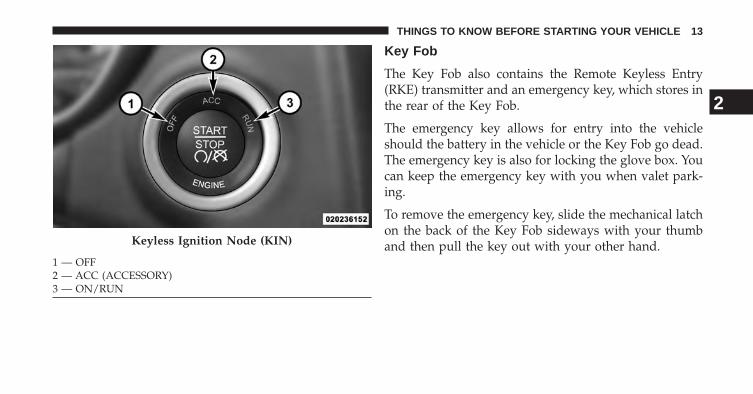
Key Fob
The Key Fob also contains the Remote Keyless Entry(RKE) transmitter and an emergency key, which stores inthe rear of the Key Fob.
The emergency key allows for entry into the vehicleshould the battery in the vehicle or the Key Fob go dead.The emergency key is also for locking the glove box. Youcan keep the emergency key with you when valet park-ing.
To remove the emergency key, slide the mechanical latchon the back of the Key Fob sideways with your thumband then pull the key out with your other hand.Keyless Ignition Node (KIN)
1 — OFF2 — ACC (ACCESSORY)3 — ON/RUN
2
THINGS TO KNOW BEFORE STARTING YOUR VEHICLE 13
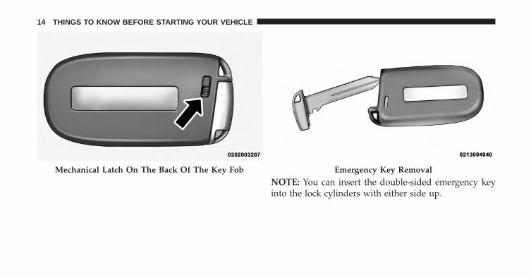
NOTE: You can insert the double-sided emergency keyinto the lock cylinders with either side up.
Mechanical Latch On The Back Of The Key Fob Emergency Key Removal
14 THINGS TO KNOW BEFORE STARTING YOUR VEHICLE
Ignition Or Accessory On Message
Opening the driver’s door when the ignition is in ACC orON (engine not running), a chime will sound to remindyou to cycle the ignition to OFF. In addition to the chime,the ignition or accessory on message will display in thecluster.
NOTE: With the Uconnect® system, the power windowswitches, radio and power outlets will remain active forup to 10 minutes after the ignition is cycled to the OFFposition. Opening either front door will cancel thisfeature. The time for this feature is programmable. Referto “Uconnect® Settings” in “Understanding Your Instru-ment Panel” for further information.
WARNING!
• When leaving the vehicle, always remove the KeyFob from the vehicle and lock your vehicle.
• Never leave children alone in a vehicle, or withaccess to an unlocked vehicle.
• Allowing children to be in a vehicle unattended isdangerous for a number of reasons. A child orothers could be seriously or fatally injured. Chil-dren should be warned not to touch the parkingbrake, brake pedal or the shift lever.
• Do not leave the Key Fob in or near the vehicle, orin a location accessible to children, and do notleave the ignition of a vehicle equipped withKeyless Enter-N-Go™ in the ACC or ON/RUNmode. A child could operate power windows, othercontrols, or move the vehicle.
(Continued)
2
THINGS TO KNOW BEFORE STARTING YOUR VEHICLE 15
WARNING! (Continued)• Do not leave children or animals inside parked
vehicles in hot weather. Interior heat build-up maycause serious injury or death.
CAUTION!
An unlocked car is an invitation to thieves. Alwaysremove the Key Fob from vehicle, cycle the ignitionOFF and lock all doors when leaving the vehicleunattended.
SENTRY KEY®
The Sentry Key® Immobilizer system prevents unauthor-ized vehicle operation by disabling the engine. Thesystem does not need to be armed or activated. Operationis automatic, regardless of whether the vehicle is lockedor unlocked.
The system uses a Key Fob with Remote Keyless Entry(RKE) transmitter, a Keyless Ignition Node (KIN) and aRF receiver to prevent unauthorized vehicle operation.Therefore, only Key Fobs that are programmed to thevehicle can be used to start and operate the vehicle.
After cycling the ignition to the ON/RUN position, theVehicle Security Light will turn on for three seconds for abulb check. If the light remains on after the bulb check, itindicates that there is a problem with the electronics. Inaddition, if the light begins to flash after the bulb check,it indicates that someone used an invalid Key Fob to startthe engine. Either of these conditions will result in theengine being shut off after two seconds.
If the Vehicle Security Light turns on during normalvehicle operation (vehicle running for longer than 10seconds), it indicates that there is a fault in the electron-ics. Should this occur, have the vehicle serviced as soonas possible by an authorized dealer.
16 THINGS TO KNOW BEFORE STARTING YOUR VEHICLE
CAUTION!
The Sentry Key® Immobilizer system is not compat-ible with some aftermarket remote starting systems.Use of these systems may result in vehicle startingproblems and loss of security protection.
All of the Key Fobs provided with your new vehicle havebeen programmed to the vehicle electronics.
Replacement Keys
NOTE: Only Key Fobs that are programmed to thevehicle electronics can be used to start and operate thevehicle. Once a Key Fob is programmed to a vehicle, itcannot be programmed to any other vehicle.
CAUTION!
• Always remove the Key Fobs from the vehicle andlock all doors when leaving the vehicle unat-tended.
• For vehicles equipped with Keyless Enter-N-Go™,always remember to place the ignition in the OFFposition.
At the time of purchase, the original owner is providedwith a four-digit Personal Identification Number (PIN).Keep the PIN in a secure location. This number isrequired for authorized dealer replacement of Key Fobs.Duplication of Key Fobs may be performed at an autho-rized dealer, this procedure consists of programming ablank Key Fob to the vehicle electronics. A blank Key Fobis one that has never been programmed.
2
THINGS TO KNOW BEFORE STARTING YOUR VEHICLE 17
NOTE: When having the Sentry Key® Immobilizer Sys-tem serviced, bring all vehicle keys with you to anauthorized dealer.
Customer Key Programming
Programming Key Fobs or RKE transmitters may beperformed at an authorized dealer.
General Information
The Sentry Key® system complies with FCC rules Part 15and with RSS-210 of Industry Canada. Operation issubject to the following conditions:
• This device may not cause harmful interference.
• This device must accept any interference that may bereceived, including interference that may cause unde-sired operation.
VEHICLE SECURITY ALARM SYSTEM
The Vehicle Security Alarm monitors the doors, liftgate,and hood for unauthorized entry and the ignition forunauthorized operation. If something triggers the alarm,the Vehicle Security Alarm will prevent the vehicle fromstarting. It will also sound the horn and flash the parklights, and taillights.
Rearming of the System
If something triggers the alarm, and no action is taken todisarm it, the Vehicle Security Alarm will turn off thehorn after three minutes, turn off all of the visual signals(flashing lights) after 15 minutes, and then rearm itself.
To Arm The System
Follow these steps to arm the Vehicle Security Alarm:
1. Make sure the vehicle ignition system is the �OFF�position.
18 THINGS TO KNOW BEFORE STARTING YOUR VEHICLE
2. Perform one of the following methods to lock thevehicle:
Press LOCK on the interior power door lock switch withthe driver and/or passenger door open.
Press the LOCK button on the Remote Keyless Entry(RKE) transmitter.
3. If any doors are open, close them.
Entering The Liftgate With The System Armed
NOTE: Using the key to open the liftgate while theVehicle Security Alarm is armed will trigger the alarm.
Press the LIFTGATE release button on the RKE transmit-ter twice to allow access without triggering the alarm orhaving to disarm the Vehicle Security Alarm. Then,within 30 seconds, open the liftgate by using the keycylinder or the LIFTGATE release switch located in theexterior liftgate handle.
To Disarm The System
The Vehicle Security Alarm can be disarmed using any ofthe following methods:
• Press the UNLOCK button on the Remote KeylessEntry (RKE) transmitter.
• Cycle the vehicle ignition system out of the OFFposition:• Press the Keyless Enter-N-Go™ Start/Stop button
(requires at least one valid Key Fob in the vehicle).
NOTE:
• The liftgate key cylinder cannot arm or disarm theVehicle Security Alarm.
• When the Vehicle Security Alarm is armed, the interiorpower door lock switches will not unlock the doors.
The Vehicle Security Alarm is designed to protect yourvehicle; however, you can create conditions where the
2
THINGS TO KNOW BEFORE STARTING YOUR VEHICLE 19
system will give you a false alarm. If one of the previ-ously described arming sequences has occurred, theVehicle Security Alarm will arm regardless of whetheryou are in the vehicle or not. If you remain in the vehicleand open a door, the alarm will sound. If this occurs,disarm the Vehicle Security Alarm.
If the Vehicle Security Alarm is armed and the batterybecomes disconnected, the Vehicle Security Alarm willremain armed when the battery is reconnected; theexterior lights will flash, the horn will sound. If thisoccurs, disarm the Vehicle Security Alarm.
Tamper Alert
If something has triggered the Vehicle Security Alarm inyour absence, the horn will sound three times and theexterior lights will blink three times when you disarm theVehicle Security Alarm. Check the vehicle for tampering.
Electronic Immobilization System
The Electronic Immobilization system prevents unau-thorized vehicle operation by disabling the engine. Thesystem does not need to be armed or activated. Operationis automatic, regardless of whether the vehicle is lockedor unlocked.
ILLUMINATED ENTRY
The interior lights will turn on whenever a door isopened or the liftgate is opened and the dimmer switch isnot in the defeat position.
The interior lights will turn on, remain on for approxi-mately 30 seconds, and then fade to off if any of thefollowing occur:
• A door is opened using the outside door handle andthen closed.
• A door is unlocked using the Remote Keyless Entry(RKE) transmitter.
20 THINGS TO KNOW BEFORE STARTING YOUR VEHICLE
The interior lights will turn on and remain on for aboutfour seconds and then fade to off if a door is openedusing the inside door handle.
NOTE: None of the courtesy lights will operate if thedimmer control is in the “defeat” position (extremedownward position), unless the overhead map/readinglights are turned on manually.
REMOTE KEYLESS ENTRY (RKE)
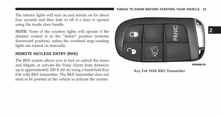
The RKE system allows you to lock or unlock the doorsand liftgate, or activate the Panic Alarm from distancesup to approximately 200 ft (60 m) using a hand-held KeyFob with RKE transmitter. The RKE transmitter does notneed to be pointed at the vehicle to activate the system.
Key Fob With RKE Transmitter
2
THINGS TO KNOW BEFORE STARTING YOUR VEHICLE 21
To Unlock The Doors
Press and release the UNLOCK button on the RKEtransmitter once to unlock the driver’s door or twice tounlock both doors and the liftgate. The park lights andturn signal lights will flash to acknowledge the signaland the illuminated entry system will turn on. refer to“Uconnect® Access Programmable Settings” in “Under-standing Your Instrument Panel” for further information.
Remote Key Unlock, Driver Door/Both Doors First
This feature lets you program the system to unlock eitherthe driver’s door or all doors on the first press of theUNLOCK button on the RKE transmitter. To change thecurrent setting, refer to “Uconnect® Access Settings” in“Understanding Your Instrument Panel” for further in-formation.
Flash Lights With Remote Key Lock
This feature lets you program the system to unlock eitherthe driver’s door or all doors on the first press of theUNLOCK button on the RKE transmitter. To change thecurrent setting, refer to “Uconnect® Access Settings” in“Understanding Your Instrument Panel” for further in-formation.
To Lock The Doors
Press and release the LOCK button on the RKE transmit-ter to lock the doors. The horn will chirp once and thepark lights and turn signal lights will flash to acknowl-edge the signal.
22 THINGS TO KNOW BEFORE STARTING YOUR VEHICLE
Sound Horn With Remote Key Lock
This feature will cause the horn to chirp when the doorsare locked with the RKE transmitter. This feature can beturned on or turned off. To change the current setting,refer to “Uconnect® Access Settings” in “UnderstandingYour Instrument Panel” for further information.
To Unlatch The Liftgate
Press the LIFTGATE button on the RKE transmitter twotimes within five seconds to unlatch the liftgate.
Using The Panic Alarm
To turn the Panic Alarm feature on or off, press and holdthe PANIC button on the RKE transmitter for at least onesecond and release. When the Panic Alarm is on, theheadlights will turn on, the park lights will flash, thehorn will pulse on and off, and the interior lights willturn on.
The Panic Alarm will stay on for three minutes unlessyou turn it off by either pressing the PANIC button asecond time or drive the vehicle at a speed of 15 mph(24 km/h) or greater.
NOTE: The interior lights will turn off if you cycle theignition switch to the ACC or ON/RUN position whilethe Panic Alarm is activated. However, the exterior lightsand horn will remain on.
Programming Additional Transmitters
Programming Key Fobs or RKE transmitters may beperformed at an authorized dealer.
Transmitter Battery Replacement
The recommended replacement battery is one CR2032battery.
2
THINGS TO KNOW BEFORE STARTING YOUR VEHICLE 23
NOTE:
• Perchlorate Material — special handling may apply.See www.dtsc.ca.gov/hazardouswaste/perchlorate
• Do not touch the battery terminals that are on the backhousing or the printed circuit board.
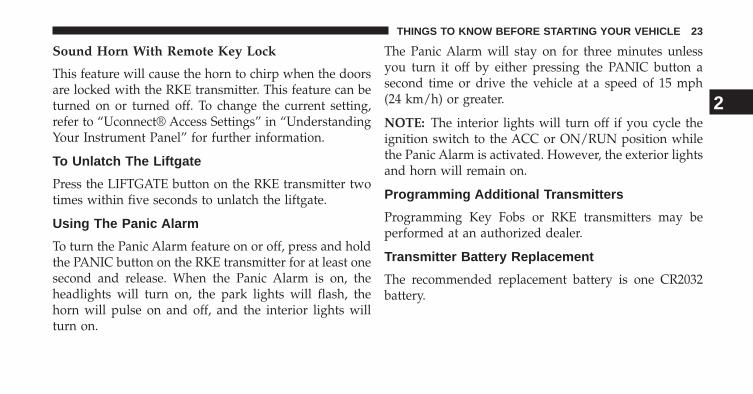
1. Remove the emergency key by sliding the mechanicallatch on the back of the RKE transmitter sidewayswith your thumb and then pull the key out with yourother hand.
2. Insert the tip of the emergency key or a #2 flat bladescrewdriver into the slot and gently pry the two halvesof the RKE transmitter apart. Make sure not to damagethe seal during removal.
Emergency Key Removal
24 THINGS TO KNOW BEFORE STARTING YOUR VEHICLE
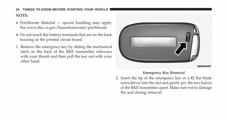
3. Remove the battery by turning the back cover over(battery facing downward) and tapping it lightly on asolid surface such as a table or similar, then replace thebattery. When replacing the battery, match the + signon the battery to the + sign on the inside of the batteryclip, located on the back cover. Avoid touching thenew battery with your fingers. Skin oils may causebattery deterioration. If you touch a battery, clean itwith rubbing alcohol.
4. To assemble the RKE transmitter case, snap the twohalves together.
Separating The RKE Transmitter Case
2
THINGS TO KNOW BEFORE STARTING YOUR VEHICLE 25
General Information
This RKE transmitter complies with FCC rules Part 15.Operation is subject to the following conditions:
1. This device may not cause harmful interference.
2. This device must accept any interference that may bereceived, including interference that may cause unde-sired operation.
If your RKE transmitter fails to operate from a normaldistance, check for these two conditions:
1. Closeness to a radio transmitter, such as a radio stationtower, airport transmitter, and some mobile or CBradios can affect transmitter operation. To verify if thisis the cause, move the vehicle to another area and testRKE transmitter operation.
2. The RKE transmitter may become “out of sync” andwill no longer function if operated more than 255times while out of range of the vehicle (23 ft or 7 m) orif operated while the vehicle battery is dead or discon-nected. To “synchronize” the RKE transmitter, cyclethe ignition to the OFF position. Close the hood and alldoors. Press both buttons on the RKE transmitter forabout 10 seconds. The horn will chirp once to ac-knowledge the signal. Normal RKE transmitter opera-tion should resume.
3. The RKE transmitter battery may be weak or dead.The expected life of the battery is a minimum of threeyears.
26 THINGS TO KNOW BEFORE STARTING YOUR VEHICLE
DOOR LOCKS
WARNING!
• Do not touch the exhaust pipe sill covers whenentering or exiting your vehicle. They can be hotenough to burn you. Observe the warning labels oneach door closure panel.
• For personal security in the event of an collision,lock the vehicle doors as you drive as well as whenyou park and leave the vehicle.
• When leaving the vehicle, always cycle the ignitionto the OFF position lock, and lock your vehicle.Unsupervised use of vehicle equipment may causesevere personal injuries and death.
(Continued)
WARNING! (Continued)• Never leave children alone in a vehicle. Leaving
unattended children in a vehicle is dangerous for anumber of reasons. A child or others could beinjured seriously or fatally. Don’t leave the ignitionin the ON position. A child could operate powerwindows, other controls, or move the vehicle.
Power Door Locks
A power door lock switch is on each door trim panel. Usethis switch to lock or unlock the doors.
WARNING!
• For personal security and safety in the event of acollision, lock the vehicle doors before you drive aswell as when you park and leave the vehicle.
(Continued)
2
THINGS TO KNOW BEFORE STARTING YOUR VEHICLE 27
WARNING! (Continued)• Never leave children alone in a vehicle, or with
access to an unlocked vehicle. Allowing children tobe in a vehicle unattended is dangerous for anumber of reasons. A child or others could beseriously or fatally injured. Children should bewarned not to touch the parking brake, brake pedalor the shift lever.
• Do not leave the Key Fob in or near the vehicle, orin a location accessible to children. A child couldoperate power windows, other controls, or movethe vehicle.
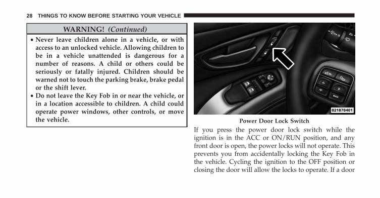
If you press the power door lock switch while theignition is in the ACC or ON/RUN position, and anyfront door is open, the power locks will not operate. Thisprevents you from accidentally locking the Key Fob inthe vehicle. Cycling the ignition to the OFF position orclosing the door will allow the locks to operate. If a door
Power Door Lock Switch
28 THINGS TO KNOW BEFORE STARTING YOUR VEHICLE
is open, and the ignition is in the ACC or ON/RUNposition, a chime will sound as a reminder to remove theKey Fob.
Automatic Door Locks
The auto door lock feature default condition is enabled.When enabled, the door locks will lock automaticallywhen the vehicle’s speed exceeds 5 mph (8 km/h). Theauto door lock feature can be enabled or disabled by yourauthorized dealer for service.
Automatic Unlock Doors On Exit
The doors will unlock automatically on vehicles withpower door locks if:
1. The Automatic Unlock Doors On Exit feature is en-abled.
2. The driver door is opened.
3. The doors were not previously unlocked.
Automatic Unlock Doors On Exit Programming
To change the current setting, refer to “Uconnect® Set-tings” in “Understanding Your Instrument Panel” forfurther information.
NOTE: Use the Automatic Unlock Doors On Exit featurein accordance with local laws.
2
THINGS TO KNOW BEFORE STARTING YOUR VEHICLE 29
WINDOWS
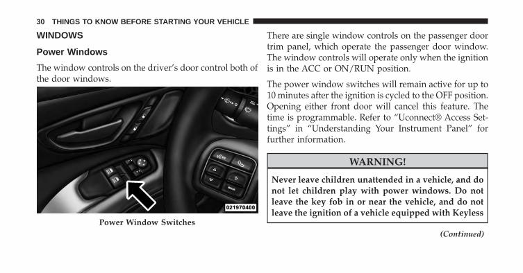
Power Windows
The window controls on the driver’s door control both ofthe door windows.
There are single window controls on the passenger doortrim panel, which operate the passenger door window.The window controls will operate only when the ignitionis in the ACC or ON/RUN position.
The power window switches will remain active for up to10 minutes after the ignition is cycled to the OFF position.Opening either front door will cancel this feature. Thetime is programmable. Refer to “Uconnect® Access Set-tings” in “Understanding Your Instrument Panel” forfurther information.
WARNING!
Never leave children unattended in a vehicle, and donot let children play with power windows. Do notleave the key fob in or near the vehicle, and do notleave the ignition of a vehicle equipped with Keyless
(Continued)Power Window Switches
30 THINGS TO KNOW BEFORE STARTING YOUR VEHICLE
WARNING! (Continued)Enter-N-Go™ in the ACC or ON/RUN mode. Occu-pants, particularly unattended children, can becomeentrapped by the windows while operating thepower window switches. Such entrapment may re-sult in serious injury or death.
Auto-Down Feature
Both power window switches have an AUTO-downfeature. Press the window switch to the second detent,release, and the window will go down automatically.
To open the window part way, press the window switchto the first detent and release it when you want thewindow to stop.
To stop the window from going all the way down duringthe AUTO-down operation, pull up on the switch briefly.
AUTO-Up Feature With Anti-Pinch Protection — IfEquipped
Lift the window switch to the second detent, release, andthe window will go up automatically.
To stop the window from going all the way up during theAUTO-up operation, push down on the switch briefly.
To close the window part way, lift the window switch tothe first detent and release it when you want the windowto stop.
NOTE:
• If the window runs into any obstacle during auto-closure, it will reverse direction and then go backdown. Remove the obstacle and use the windowswitch again to close the window.
2
THINGS TO KNOW BEFORE STARTING YOUR VEHICLE 31
• Any impact due to rough road conditions may triggerthe auto-reverse function unexpectedly during auto-closure. If this happens, pull the switch lightly to thefirst detent and hold to close the window manually.
WARNING!
There is no anti-pinch protection when the windowis almost closed. Be sure to clear all objects from thewindow before closing.
Reset Auto-Up
Should the Auto Up feature stop working, the windowprobably needs to be reset. To reset Auto Up:
1. Make sure the door is fully closed.
2. Pull the window switch up to close the windowcompletely and continue to hold the switch up for anadditional two seconds after the window is closed.
3. Push the window switch down firmly to the seconddetent to open the window completely and continueto hold the switch down for an additional two secondsafter the window is fully open.
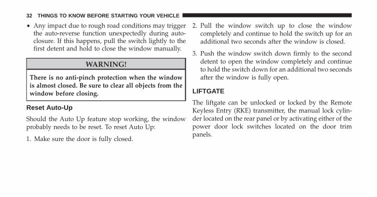
LIFTGATE
The liftgate can be unlocked or locked by the RemoteKeyless Entry (RKE) transmitter, the manual lock cylin-der located on the rear panel or by activating either of thepower door lock switches located on the door trimpanels.
32 THINGS TO KNOW BEFORE STARTING YOUR VEHICLE
To unlock the liftgate with the RKE transmitter, press theLIFTGATE button on the RKE transmitter two times.
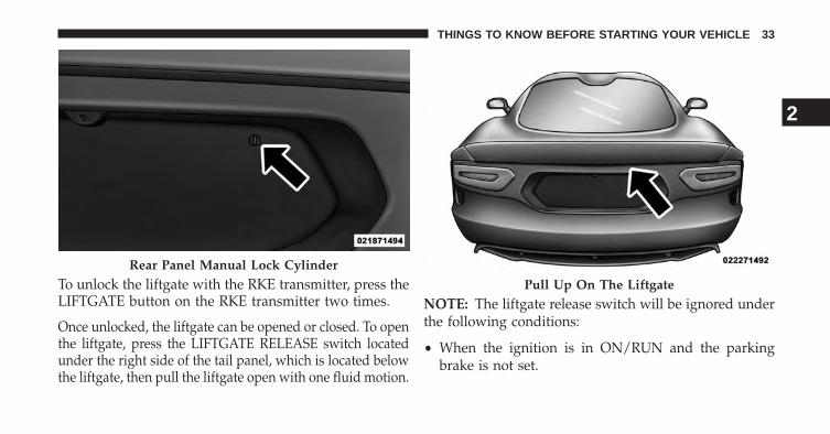
Once unlocked, the liftgate can be opened or closed. To openthe liftgate, press the LIFTGATE RELEASE switch locatedunder the right side of the tail panel, which is located belowthe liftgate, then pull the liftgate open with one fluid motion.
NOTE: The liftgate release switch will be ignored underthe following conditions:
• When the ignition is in ON/RUN and the parkingbrake is not set.
Rear Panel Manual Lock Cylinder
Pull Up On The Liftgate
2
THINGS TO KNOW BEFORE STARTING YOUR VEHICLE 33
• When vehicle speed is not 0 mph (0 km/h).
• When all doors are locked (except for RKE transmitterliftgate access). Refer to “Entering the Liftgate with theSystem Armed — Coupe” under “Security AlarmSystem” for additional information.
The liftgate ajar icon will illuminate in the ElectronicVehicle Information Center (EVIC) when the liftgate isopen.
WARNING!
• Driving with the liftgate open can allow poisonousexhaust gases into your vehicle. You and yourpassengers could be injured by these fumes. Keepthe liftgate closed when you are operating thevehicle.
(Continued)
WARNING! (Continued)• If you are required to drive with the liftgate open,
make sure that all windows are closed, and theclimate control blower switch is set at high speed.Do not use the recirculation mode.
Gas props support the liftgate in the open position.However, because the gas pressure drops with tempera-ture, it may be necessary to assist the props whenopening the liftgate in cold weather.
OCCUPANT RESTRAINTS
Some of the most important safety features in yourvehicle are the restraint systems:
• Three-point lap and shoulder belts for all seatingpositions
• Advanced Front Air Bags for driver and front passen-ger
34 THINGS TO KNOW BEFORE STARTING YOUR VEHICLE
• An energy-absorbing steering column and steeringwheel
• Knee bolsters/blockers for front seat occupants
• Seat belts incorporate pretensioners to enhance occu-pant protection by managing occupant energy duringan impact event
• Passenger side seatbelt incorporates an Automatic Lock-ing Retractor (ALR), which locks the seat belt webbinginto position by extending the belt all the way out andthen adjusting the belt to the desired length to restrain achild seat or secure a large item in a seat — if equipped
If you will be carrying children too small for adult-sizedseat belts, the seat belts or tether anchor feature also canbe used to hold infant and child restraint systems. Formore information on the tether anchor, refer to ChildRestraint Tether Anchor.
WARNING!
• Never place a rear facing infant seat in front of anair bag. A deploying passenger Advanced Front AirBag can cause death or serious injury to a child 12years or younger, including a child in a rearwardfacing infant seat.
• Only use a rearward-facing child restraint in avehicle with a rear seat.
NOTE: The Advanced Front Air bags have a multistageinflator design. This allows the air bag to have differentrates of inflation based on several factors, including theseverity and type of collision.
Please pay close attention to the information in thissection. It tells you how to use your restraint systemproperly, to keep you and your passengers as safe aspossible.
2
THINGS TO KNOW BEFORE STARTING YOUR VEHICLE 35
WARNING!
In a collision, you and your passengers can suffermuch greater injuries if you are not properly buckledup. You can strike the interior of your vehicle or otherpassengers, or you can be thrown out of the vehicle.Always be sure you and others in your vehicle arebuckled up properly.
Buckle up even though you are an excellent driver, evenon short trips. Someone on the road may be a poor driverand cause an collision that includes you. This can happenfar away from home or on your own street.
Research has shown that seat belts save lives, and theycan reduce the seriousness of injuries in an collision.Some of the worst injuries happen when people arethrown from the vehicle. Seat belts reduce the possibilityof ejection and the risk of injury caused by striking theinside of the vehicle. Everyone in a motor vehicle shouldbe belted at all times.
Lap/Shoulder Belts
Each seat belt is a combined lap/shoulder belt system.The belt webbing retractor will lock only during verysudden stops or impacts. This feature allows the shoulderportion of the belt to move freely with you under normalconditions. However, in an collision, the belt will lockand reduce your risk of striking the inside of the vehicleor being thrown out of the vehicle.
36 THINGS TO KNOW BEFORE STARTING YOUR VEHICLE
WARNING!
• It is extremely dangerous to ride in a cargo area,inside or outside of a vehicle. In a collision, peopleriding in these areas are more likely to be seriouslyinjured or killed.
• Do not allow people to ride in any area of yourvehicle that is not equipped with seats and seatbelts.
• Be sure everyone in your vehicle is in a seat andusing a seat belt properly.
• Wearing a seat belt incorrectly is dangerous. Seatbelts are designed to go around the large bones ofyour body. These are the strongest parts of yourbody and can take the force of a collision they best.
(Continued)
WARNING! (Continued)• Wearing your belt in the wrong place can make
your injuries in a collision much worse. You mightsuffer internal injuries, or you could even slide outof part of the belt. Follow these instructions wearyou seat belt safely and to keep your passengerssafe, too.
• Two people should never be belted into a singleseat belt. People belted together can crash into oneanother in an collision, hurting one another badly.Never use a lap/shoulder belt or a lap belt for morethan one person, no matter what their size.
2
THINGS TO KNOW BEFORE STARTING YOUR VEHICLE 37
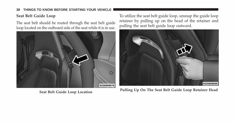
Seat Belt Guide Loop
The seat belt should be routed through the seat belt guideloop located on the outboard side of the seat while it is in use.
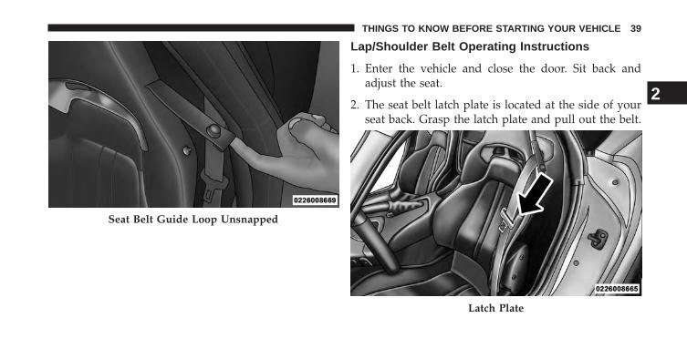
To utilize the seat belt guide loop, unsnap the guide loopretainer by pulling up on the head of the retainer andpulling the seat belt guide loop outward.
Seat Belt Guide Loop Location Pulling Up On The Seat Belt Guide Loop Retainer Head
38 THINGS TO KNOW BEFORE STARTING YOUR VEHICLE
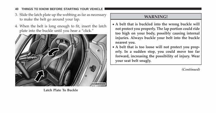
Lap/Shoulder Belt Operating Instructions
1. Enter the vehicle and close the door. Sit back andadjust the seat.
2. The seat belt latch plate is located at the side of yourseat back. Grasp the latch plate and pull out the belt.
Seat Belt Guide Loop Unsnapped
Latch Plate
2
THINGS TO KNOW BEFORE STARTING YOUR VEHICLE 39
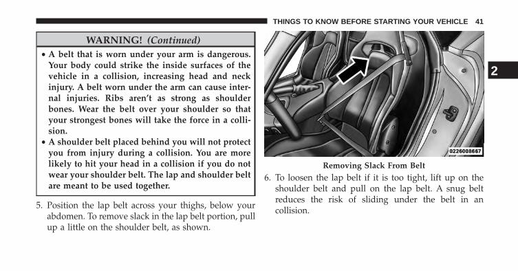
3. Slide the latch plate up the webbing as far as necessaryto make the belt go around your lap.
4. When the belt is long enough to fit, insert the latchplate into the buckle until you hear a “click.”
WARNING!
• A belt that is buckled into the wrong buckle willnot protect you properly. The lap portion could ridetoo high on your body, possibly causing internalinjuries. Always buckle your belt into the bucklenearest you.
• A belt that is too loose will not protect you prop-erly. In a sudden stop, you could move too farforward, increasing the possibility of injury. Wearyour seat belt snugly.
(Continued)
Latch Plate To Buckle
40 THINGS TO KNOW BEFORE STARTING YOUR VEHICLE
WARNING! (Continued)• A belt that is worn under your arm is dangerous.
Your body could strike the inside surfaces of thevehicle in a collision, increasing head and neckinjury. A belt worn under the arm can cause inter-nal injuries. Ribs aren’t as strong as shoulderbones. Wear the belt over your shoulder so thatyour strongest bones will take the force in a colli-sion.
• A shoulder belt placed behind you will not protectyou from injury during a collision. You are morelikely to hit your head in a collision if you do notwear your shoulder belt. The lap and shoulder beltare meant to be used together.
5. Position the lap belt across your thighs, below yourabdomen. To remove slack in the lap belt portion, pullup a little on the shoulder belt, as shown.
6. To loosen the lap belt if it is too tight, lift up on theshoulder belt and pull on the lap belt. A snug beltreduces the risk of sliding under the belt in ancollision.
Removing Slack From Belt
2
THINGS TO KNOW BEFORE STARTING YOUR VEHICLE 41
WARNING!
• A lap belt worn too high can increase the risk ofinjury in a collision. The belt forces won’t be at thestrong hip and pelvic bones, but across your abdo-men. Always wear the lap part of your seat belt aslow as possible and keep it snug.
• A twisted belt may not protect you properly. In acollision, it could even cut into you. Be sure the beltis straight. If you can’t straighten a belt in yourvehicle, take it to your authorized dealer immedi-ately and have it fixed.
7. Position the shoulder belt on your chest so that it iscomfortable and not resting on your neck. The retrac-tor will withdraw any slack in the belt.
8. To release the belt, push the red button in the buckle.The belt will retract automatically to its stowed posi-tion. If necessary, slide the latch plate down thewebbing to allow it to retract fully.
WARNING!
A frayed or torn belt could rip apart in a collision andleave you with no protection. Inspect the belt systemperiodically, checking for cuts, frays, or loose parts.Damaged parts must be replaced immediately. Donot disassemble or modify the system. Seat beltassemblies must be replaced after a collision if theyhave been damaged (bent retractor, torn webbing,etc.).
42 THINGS TO KNOW BEFORE STARTING YOUR VEHICLE

Lap/Shoulder Belt Untwisting Procedure
Use the following procedure to untwist a twisted lap/shoulder belt.
1. Position the latch plate as close as possible to theanchor point.
2. At about 6 to 12 in (15 to 30 cm) above the latch plate,grasp and twist the belt webbing 180 degrees to createa fold that begins immediately above the latch plate.
3. Slide the latch plate upward over the folded webbing.The folded webbing must enter the slot at the top ofthe latch plate.
4. Continue to slide the latch plate up until it clears thefolded webbing.
Automatic Locking Retractor Mode (ALR) — IfEquipped
In this mode, the shoulder belt is automatically pre-locked. The belt will still retract to remove any slack inthe shoulder belt. The Automatic Locking Mode is avail-able on all passenger-seating positions with a combina-tion lap/shoulder belt. Use the Automatic Locking Modeanytime a child safety seat is installed in a seatingposition that has a belt with this feature. Children 12years old and under should always be properly re-strained in a vehicle with a rear seat.
How To Engage The Automatic Locking Mode
1. Buckle the combination lap and shoulder belt.
2. Grasp the shoulder portion and pull downward untilthe entire belt is extracted.
2
THINGS TO KNOW BEFORE STARTING YOUR VEHICLE 43
3. Allow the belt to retract. As the belt retracts, you willhear a clicking sound. This indicates the safety belt isnow in the Automatic Locking Mode.
How To Disengage The Automatic Locking Mode
Unbuckle the combination lap/shoulder belt and allow itto retract completely to disengage the Automatic LockingMode and activate the vehicle sensitive (emergency)locking mode.
WARNING!
• The belt and retractor assembly must be replaced ifthe seat belt assembly Automatic Locking Retractor(ALR) feature or any other seat belt function is notworking properly when checked according to theprocedures in the Service Manual.
• Failure to replace the belt and retractor assemblycould increase the risk of injury in collisions.
Seat Belt Pretensioners
The seat belts for both front seating positions areequipped with pretensioning devices that are designed toremove slack from the seat belt in the event of ancollision. These devices may improve the performance ofthe seat belt by assuring that the belt is tight about theoccupant early in an collision. Pretensioners work for allsize occupants, including those in child restraints.
NOTE: These devices are not a substitute for proper seatbelt placement by the occupant. The seat belt still must beworn snugly and positioned properly.
The pretensioners are triggered by the Occupant Re-straint Controller (ORC). Like the air bags, the preten-sioners are single use items. A deployed pretensioner ora deployed air bag must be replaced immediately.
44 THINGS TO KNOW BEFORE STARTING YOUR VEHICLE
Enhanced Seat Belt Use Reminder System(BeltAlert®)
BeltAlert® is a feature intended to remind the driver andfront passenger (if equipped with front passengerBeltAlert®) to fasten their seat belts. The feature is activewhenever the ignition is on. If the driver or front seatpassenger is unbelted, the Seat Belt Reminder Light willturn on and remain on until both front seat belts arefastened.
The BeltAlert® warning sequence begins after the vehiclespeed is over 5 mph (8 km/h), by blinking the Seat BeltReminder Light and sounding an intermittent chime.Once the sequence starts, it will continue for the entireduration or until the respective seatbelts are fastened.After the sequence completes, the Seat Belt ReminderLight remains illuminated until the respective seat beltsare fastened. The driver should instruct all other occu-pants to fasten their seat belts. If a front seat belt is
unbuckled while traveling at speeds greater than 5 mph(8 km/h), BeltAlert® will provide both audio and visualnotification.
The front passenger seat BeltAlert® is not active whenthe front passenger seat is unoccupied. BeltAlert® maybe triggered when an animal or heavy object is on thefront passenger seat or when the seat is folded flat (ifequipped). It is recommended that pets be restrained inthe rear seat (if equipped) in pet harnesses or pet carriersthat are secured by seat belts, and cargo is properlystowed.
BeltAlert® can be enabled or disabled by your autho-rized dealer. Chrysler Group LLC does not recommenddeactivating BeltAlert®.
NOTE: Although BeltAlert® has been deactivated, theSeat Belt Reminder Light will continue to illuminatewhile the driver’s or front passenger (if equipped withBeltAlert®) seat belt remains unfastened.
2
THINGS TO KNOW BEFORE STARTING YOUR VEHICLE 45
Seat Belts and Pregnant Women
We recommend that pregnant women use the seat beltsthroughout their pregnancy. Keeping the mother safe isthe best way to keep the baby safe.
Pregnant women should wear the lap portion of the beltacross the thighs and as snug across the hips as possible.Keep the belt low so that it does not come across theabdomen. That way the strong bones of the hips will takethe force if there is an collision.
Seat Belt Extender
If a seat belt is too short, even when extended fully, yourauthorized dealer can provide you with a seat beltextender. This extender should only be used if theexisting belt is not long enough. When it is not required,remove the extender, and store it.
WARNING!
Using a seat belt extender when not needed canincrease the risk of injury in a collision. Only use theseat belt extender when the lap belt is not longenough when it is worn low and snug, and in therecommended seating positions. Remove and storethe extender when not needed.
Supplemental Restraint System (SRS) — Air Bags
This vehicle has Advanced Front Air Bags for the driverand passenger as a supplement to the seat belt restraintsystems. The driver’s Advanced Front Air Bag ismounted in the steering wheel. The passenger’s Ad-vanced Front Air Bag is mounted underneath a cover inthe passenger’s side of the instrument panel. The wordsSRS/AIRBAG is embossed on the air bag covers.
46 THINGS TO KNOW BEFORE STARTING YOUR VEHICLE
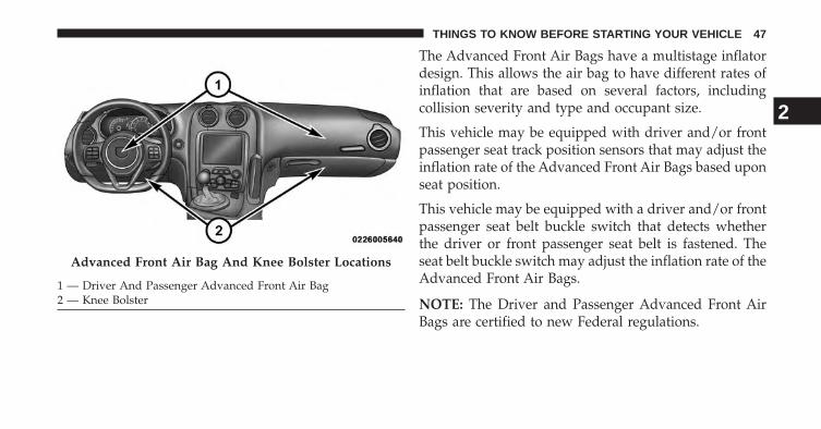
The Advanced Front Air Bags have a multistage inflatordesign. This allows the air bag to have different rates ofinflation that are based on several factors, includingcollision severity and type and occupant size.
This vehicle may be equipped with driver and/or frontpassenger seat track position sensors that may adjust theinflation rate of the Advanced Front Air Bags based uponseat position.
This vehicle may be equipped with a driver and/or frontpassenger seat belt buckle switch that detects whetherthe driver or front passenger seat belt is fastened. Theseat belt buckle switch may adjust the inflation rate of theAdvanced Front Air Bags.
NOTE: The Driver and Passenger Advanced Front AirBags are certified to new Federal regulations.
Advanced Front Air Bag And Knee Bolster Locations
1 — Driver And Passenger Advanced Front Air Bag2 — Knee Bolster
2
THINGS TO KNOW BEFORE STARTING YOUR VEHICLE 47
WARNING!
• No objects should be placed over or near the airbag on the instrument panel, because any suchobjects could cause harm if the vehicle is in acollision severe enough to cause the air bag toinflate.
• Do not put anything on or around the air bagcovers or attempt to open them manually. You maydamage the air bags and you could be injuredbecause the air bags may no longer be functional.The protective covers for the air bag cushions aredesigned to open only when the air bags areinflating.
• Do not drill, cut or tamper with the knee bolster inany way.
(Continued)
WARNING! (Continued)• Do not mount any accessories to the knee bolster
such as alarm lights, stereos, citizen band radios,etc.
• Relying on the air bags alone could lead to moresevere injuries in a collision. The air bags workwith your seat belt to restrain you properly. Insome collisions, air bags won’t deploy at all. Al-ways wear your seat belts even though you have airbags.
• Being too close to the steering wheel or instrumentpanel during air bag deployment could cause seri-ous injury. Air bags need room to inflate. Sit back,extending your arms comfortably to reach the steer-ing wheel or instrument panel.
48 THINGS TO KNOW BEFORE STARTING YOUR VEHICLE
NOTE:
• The passenger Advanced Front Air Bag may be deac-tivated if the Occupant Classification System (refer to“Air Bag Deployment Sensors And Controls”) esti-mates the seat is empty or is occupied by someone thatis classified in the “child” category. This could be achild, a teenager, or even a small adult. Therefore, evenif the driver’s Advanced Front Air Bag deploys, thepassenger’s Advanced Front Air Bag may not deploy.
• Air bag covers may not be obvious in the interior trim;but they will open during air bag deployment.
• After any collision, the vehicle should be taken to anauthorized dealer immediately.
Here are some simple steps you can take to minimizethe risk of harm from a deploying air bag:
1. Children 12 years old and under should always ridebuckled up in a vehicle with a rear seat.
WARNING!
• Never place a rear facing infant seat in front of anair bag. A deploying passenger Advanced Front AirBag can cause death or serious injury to a child 12years or younger, including a child in a rearwardfacing infant seat.
• Only use a rearward-facing child restraint in avehicle with a rear seat.
Children that are not big enough to wear the vehicle seatbelt properly (see section on Child Restraints) should besecured in a vehicle with a rear seat in child restraints orbelt positioning booster seats. Older children who do notuse child restraints or belt-positioning booster seats
2
THINGS TO KNOW BEFORE STARTING YOUR VEHICLE 49
should ride properly buckled up in a vehicle with a rearseat. Never allow children to slide the shoulder beltbehind them or under their arm.
If a child from 2 to 12 years old (not in a rear facing childseat) must ride in the front passenger seat, move the seatas far back as possible and use the proper child restraint.(Refer to “Child Restraints”) You should read the instruc-tions provided with your child restraint to make sure thatyou are using it properly.
2. All occupants should always wear their lap andshoulder belts properly.
3. The driver and front passenger seats should be movedback as far as practical to allow the Advanced FrontAir Bags room to inflate.
4. If the air bag system in this vehicle needs to bemodified to accommodate a disabled person, contactthe Customer Center. Phone numbers are providedunder “If You Need Assistance.”
Air Bag System Components
Your vehicle may be equipped with the following air bagsystem components:
• Occupant Restraint Controller (ORC)
• Air Bag Warning Light
• Steering Wheel and Column
• Instrument Panel
• Knee Impact Bolsters
• Driver Advanced Front Air Bag
• Passenger Advanced Front Air Bag
• Front Impact Sensors
• Front Seat Belt Pretensioners, Seat Belt Buckle Switch,and Seat Track Position Sensors
50 THINGS TO KNOW BEFORE STARTING YOUR VEHICLE
• Occupant Classification System (OCS)• Occupant Classification Module (OCM)• Passenger Air Bag Disable (PAD) Indicator Light• Bladder• Belt Tension Sensor
Advanced Front Air Bag Features
The Advanced Front Air Bag system has multistagedriver and front passenger air bags. This system providesoutput appropriate to the severity and type of collision asdetermined by the Occupant Restraint Controller (ORC),which may receive information from the front impactsensors.
The first stage inflator is triggered immediately during animpact that requires air bag deployment. This low outputis used in less severe collisions. A higher energy output isused for more severe collisions.
Knee Impact Bolsters
The Knee Impact Bolsters help protect the knees of thedriver and front passenger, and position the front occu-pants for the best interaction with the Advanced FrontAir Bags.
Along with seat belts and pretensioners, Advanced FrontAir Bags work with the knee impact bolsters to provideimproved protection for the driver and front passenger.
Air Bag Deployment Sensors And Controls
Occupant Restraint Controller (ORC)
The ORC is part of a Federally regulated safety systemrequired for this vehicle.
The ORC determines if deployment of the front air bagsin a frontal collision is required. Based on the impactsensors signals, a central electronic ORC deploys theAdvanced Front Air Bags, and seat belt pretentioners, asrequired, depending on several factors, including the
2
THINGS TO KNOW BEFORE STARTING YOUR VEHICLE 51
severity and type of impact. The ORC may deactivate thePassenger Advanced Front Air Bag based on input fromthe Occupant Classification System (OCS).
Advanced Front Air Bags are designed to provide addi-tional protection by supplementing the seat belts incertain frontal collisions depending on the severity andtype of collision. Advanced Front Air Bags are notexpected to reduce the risk of injury in rear, side, orrollover collisions.
The Advanced Front Air Bags will not deploy in allfrontal collisions, including some that may produce sub-stantial vehicle damage — for example, some pole colli-sions, truck underrides, and angle offset collisions. Onthe other hand, depending on the type and location ofimpact, Advanced Front Air Bags may deploy in crasheswith little vehicle front-end damage but that produce asevere initial deceleration.
Because air bag sensors measure vehicle decelerationover time, vehicle speed and damage by themselves arenot good indicators of whether or not an air bag shouldhave deployed.
Seat belts are necessary for your protection in all colli-sions, and also are needed to help keep you in position,away from an inflating air bag.
The ORC monitors the readiness of the electronic parts ofthe air bag system whenever the ignition is in the STARTor ON/RUN position. If the ignition is in the OFFposition, in the ACC position, the air bag system is not onand the air bags will not inflate.
The ORC contains a backup power supply system thatmay deploy the air bags even if the battery loses power orit becomes disconnected prior to deployment.
The ORC turns on the Air Bag Warning Light andPassenger Air Bag Disable (PAD) Indicator Light for
52 THINGS TO KNOW BEFORE STARTING YOUR VEHICLE
four to eight seconds as a self-check when the ignition isfirst turned to ON/RUN. After the self-check, the Air BagWarning Light will turn off and the PAD Indicator Lightwill function normally (Refer to “Passenger Air BagDisable (PAD) Indicator Light”). If the ORC detects amalfunction in any part of the system, it turns on the AirBag Warning Light either momentarily or continuously.A single chime will sound if the light comes on againafter initial startup.
It also includes diagnostics that will illuminate the instru-ment cluster Air Bag Warning Light if a malfunction isnoted that could affect the Air Bag system. The diagnos-tics also record the nature of the malfunction.
WARNING!
Ignoring the Air Bag Warning Light in your instru-ment panel could mean you won’t have the air bags
(Continued)
WARNING! (Continued)to protect you in a collision. If the light does not comeon as a bulb check when the ignition is first turnedon, stays on after you start the vehicle, or if it comeson as you drive, have an authorized dealer service theair bag system immediately.
Driver Air Bag/Passenger Advanced Front Air BagInflator Units
The Driver Advanced Front Air Bag Inflator Unit ismounted in the steering wheel. The Passenger AdvancedFront Air Bag Inflator Unit is mounted underneath acover in the passenger side of the instrument panel.When the ORC detects a collision requiring the Ad-vanced Front Air Bags, it signals the inflator units. A largequantity of non-toxic gas is generated to inflate theAdvanced Front Air Bags. Different air bag inflation ratesmay be possible based on several factors, includingcollision type, severity and occupant size. The steering
2
THINGS TO KNOW BEFORE STARTING YOUR VEHICLE 53
wheel hub trim cover and the upper right side of theinstrument panel separate and then fold out of the way,as the air bags inflate to their full size. The air bags inflatefully in about 50 to 70 ms. This is about half of the timeit takes to blink your eyes. The air bags then deflatequickly while helping to restrain the driver and passen-ger. The Advanced Front Air Bag gas is vented towardthe instrument panel through vent holes in the air bagmaterial. In this way, the air bags do not interfere withyour control of the vehicle.
Occupant Classification System (OCS) — FrontPassenger Seat
The OCS is part of a Federally regulated safety system forthis vehicle. It is designed to deactivate the front passen-ger Advanced Front Air Bag for an unoccupied seat andfor occupants classified in a category other than a prop-erly seated adult. This could be a child, teenager, or evenan adult.
WARNING!
• Never place a rear facing infant seat in front of anair bag. A deploying passenger Advanced Front AirBag can cause death or serious injury to a child 12years or younger, including a child in a rearwardfacing infant seat.
• Only use a rearward-facing child restraint in avehicle with a rear seat.
The Passenger Advanced Front Air Bag may be deacti-vated if the OCS estimates that:
• The front passenger seat is unoccupied or has verylight objects in it
• The front passenger seat is occupied by a rearward-facing infant seat
54 THINGS TO KNOW BEFORE STARTING YOUR VEHICLE
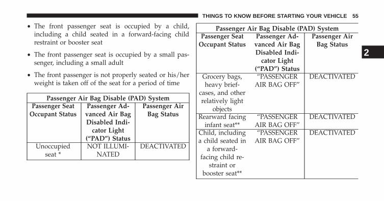
• The front passenger seat is occupied by a child,including a child seated in a forward-facing childrestraint or booster seat
• The front passenger seat is occupied by a small pas-senger, including a small adult
• The front passenger is not properly seated or his/herweight is taken off of the seat for a period of time
Passenger Air Bag Disable (PAD) SystemPassenger Seat
Occupant StatusPassenger Ad-
vanced Air BagDisabled Indi-
cator Light(“PAD”) Status
Passenger AirBag Status
Unoccupiedseat *
NOT ILLUMI-NATED
DEACTIVATED
Passenger Air Bag Disable (PAD) SystemPassenger Seat
Occupant StatusPassenger Ad-
vanced Air BagDisabled Indi-
cator Light(“PAD”) Status
Passenger AirBag Status
Grocery bags,heavy brief-
cases, and otherrelatively light
objects
“PASSENGERAIR BAG OFF”
DEACTIVATED
Rearward facinginfant seat**
“PASSENGERAIR BAG OFF”
DEACTIVATED
Child, includinga child seated in
a forward-facing child re-
straint orbooster seat**
“PASSENGERAIR BAG OFF”
DEACTIVATED
2
THINGS TO KNOW BEFORE STARTING YOUR VEHICLE 55
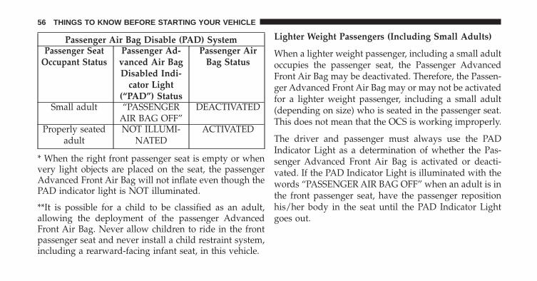
Passenger Air Bag Disable (PAD) SystemPassenger Seat
Occupant StatusPassenger Ad-
vanced Air BagDisabled Indi-
cator Light(“PAD”) Status
Passenger AirBag Status
Small adult “PASSENGERAIR BAG OFF”
DEACTIVATED
Properly seatedadult
NOT ILLUMI-NATED
ACTIVATED
* When the right front passenger seat is empty or whenvery light objects are placed on the seat, the passengerAdvanced Front Air Bag will not inflate even though thePAD indicator light is NOT illuminated.
**It is possible for a child to be classified as an adult,allowing the deployment of the passenger AdvancedFront Air Bag. Never allow children to ride in the frontpassenger seat and never install a child restraint system,including a rearward-facing infant seat, in this vehicle.
Lighter Weight Passengers (Including Small Adults)
When a lighter weight passenger, including a small adultoccupies the passenger seat, the Passenger AdvancedFront Air Bag may be deactivated. Therefore, the Passen-ger Advanced Front Air Bag may or may not be activatedfor a lighter weight passenger, including a small adult(depending on size) who is seated in the passenger seat.This does not mean that the OCS is working improperly.
The driver and passenger must always use the PADIndicator Light as a determination of whether the Pas-senger Advanced Front Air Bag is activated or deacti-vated. If the PAD Indicator Light is illuminated with thewords “PASSENGER AIR BAG OFF” when an adult is inthe front passenger seat, have the passenger repositionhis/her body in the seat until the PAD Indicator Lightgoes out.
56 THINGS TO KNOW BEFORE STARTING YOUR VEHICLE
If the PAD Indicator Light is illuminated with the words“PASSENGER AIR BAG OFF” the Passenger AdvancedFront Air Bag will not inflate in the event of a collision.
The Occupant Classification System (OCS) consists ofthe following:
• Occupant Restraint Controller (ORC)
• Occupant Classification Module (OCM) located under-neath the front passenger seat
• Bladder located beneath the passenger seat cushionfoam
• Passenger Air Bag Disabled (PAD) Indicator Light– an amber light located in the center of the instrumentpanel
• Air Bag Warning Light
Occupant Classification Module (OCM)
The Occupant Classification Module (OCM) is locatedunderneath the passenger seat.
The OCM uses input from the Bladder to classify theoccupant in the passenger seat into a size category. TheOCM communicates this information to the ORC. TheORC may deactivate the Passenger Advanced Front AirBag deployment based on occupant classification.
Bladder
The Bladder is located beneath the passenger seat cush-ion foam. The Bladder sends signals to the OCM forclassifying the occupant in the front passenger seat. Anyweight on the seat will be sensed by the Bladder. In orderfor the OCS to operate as designed, it is important for thefront passenger to be seated properly and properlywearing the seat belt.
2
THINGS TO KNOW BEFORE STARTING YOUR VEHICLE 57

Properly seated passengers are:
• Sitting upright
• Facing forward
• Sitting in the center of the seat with their feet comfort-ably on or near the floor
• Sitting with their back against the seat back and theseat back in an upright position
WARNING!
Occupants in the front passenger seat sitting improperlymay deactivate the Passenger Advanced Front Air Bag.This may result in serious injury or death in a collision.Always wear your seat belt and sit properly, with the seatback in an upright position, your back against the seatback, sitting upright, facing forward, in the center of theseat, with your feet comfortably on or near the floor.
Do not decrease the passenger’s total seated weight onthe passenger seat
Decreasing the passenger’s total seated weight on thepassenger seat may result in serious injury or death. TheOCS determines the most probable classification of theoccupant that it detects. The OCS bladder will detect thepassenger’s decreased total seated weight, which mayresult in deactivation of the Passenger Advanced FrontAir Bag in a collision and may cause serious injury ordeath. This does not mean that the OCS is workingimproperly. Decreasing the passenger’s total seatedweight on the passenger seat may result in deactivationof the Passenger Advanced Front Air Bag under certainconditions, for example:
• The front passenger’s weight is transferred to anotherpart of the vehicle (like the door, arm rest or instru-ment panel)
58 THINGS TO KNOW BEFORE STARTING YOUR VEHICLE
• The front passenger leans forward, sideways or turnsaround
• The front passenger seatback is not in the full uprightposition
• Objects are lodged under the passenger seat
• Objects are lodged between the passenger seat andcenter console
• Anything that may decrease the passenger’s totalseated weight
Do not increase the passenger’s total seated weight onthe passenger seat
Increasing the passenger’s total seated weight on thepassenger seat may result in serious injury or death. TheOCS determines the most probable classification of theoccupant that it detects. The OCS bladder will detect thepassenger’s increased total seated weight, which may
result in activation of the Passenger Advanced Front AirBag in a collision and may cause serious injury or death.This does not mean that the OCS is working improperly.Increasing the passenger’s total seated weight on thepassenger seat may result in activation of the PassengerAdvanced Front Air Bag under certain conditions, forexample:
• The front passenger leans forward, sideways or turnsaround
• The front passenger seatback is not in the full uprightposition
• The front passenger carries or holds an object whileseated (e.g., backpack, box, etc.)
• Objects are lodged under the passenger seat
• Objects are lodged between the passenger seat andcenter console
2
THINGS TO KNOW BEFORE STARTING YOUR VEHICLE 59
• Accessories that may increase the total seated weight onthe passenger seat are attached to the passenger seat
• Anything that may increase the passenger’s totalseated weight
The Air Bag Warning Light will illuminate wheneverthe OCS is unable to classify the front passenger seatstatus or when there is a fault present in the OCS.
WARNING!
Ignoring the Air Bag Warning Light in your instru-ment panel could mean you won’t have the air bagsto protect you in a collision. If the light does not comeon as a bulb check when the ignition is first turnedon, stays on after you start the vehicle, or if it comeson as you drive, have an authorized dealer service theair bag system immediately.
WARNING!
If there is a fault present in the OCS, both the PADIndicator Light and the Air Bag Warning Light willilluminate to show that the Passenger AdvancedFront Air Bag is deactivated. Should this occur, thePassenger Advanced Front Air Bag will remain deac-tivated until the fault is cleared. This indicates thatyou should take the vehicle to an authorized dealerfor service immediately.
Passenger Advanced Front Air Bag Disabled (PAD)Indicator Light
The PAD Indicator Light (an amber light located in thecenter of the instrument panel) tells the driver and frontpassenger when the Passenger Advanced Front Air Bag isdeactivated. The PAD Indicator light illuminates thewords “PASSENGER AIR BAG OFF” to show that thePassenger Advanced Front Air Bag will not inflate during
60 THINGS TO KNOW BEFORE STARTING YOUR VEHICLE
a collision. When the right front passenger seat is emptyor when very light objects are placed on the seat, thePassenger Advanced Front Air Bag will not inflate eventhough the PAD indicator light is not illuminated.
The PAD indicator light should not be illuminated whenan adult passenger is properly seated in the front passen-ger seat. In this case, the Passenger Advanced Front AirBag is ready to be inflated if a collision requires Passen-ger Advanced Front Air Bag deployment. Drivers andadult passengers should verify that the PAD IndicatorLight is not illuminated when an adult is riding in thefront passenger seat. If an adult occupant’s weight istransferred to another part of the vehicle (like the door orinstrument panel), the Passenger Advanced Front AirBag may be deactivated and the PAD Indicator Light willbe illuminated.
The Passenger Advanced Front Air Bag will be deacti-vated for most any size child who is seated properly inthe passenger seat and for most properly installed childrestraint systems. However, under certain conditions,even with a properly installed child restraint system, thePAD Indicator Light may not be illuminated, eventhough the Advanced Front Air Bag is deactivated. Thiscan occur if the child restraint is lighter than the thresh-old weight necessary to illuminate the PAD IndicatorLight. In any case, DO NOT assume the passengerAdvanced Front Air Bag is deactivated unless the PADIndicator Light is illuminated with the words “PASSEN-GER AIR BAG OFF.”
2
THINGS TO KNOW BEFORE STARTING YOUR VEHICLE 61
If the PAD Indicator Light is Illuminated for an AdultPassenger:
If an adult passenger is seated in the passenger seat, butthe PAD Indicator Light is illuminated, the passengermay be sitting improperly. Follow the steps below toallow the OCS to detect the adult passenger’s total seatedweight to activate the Passenger Advanced Front Air Bag:
1. Turn off the vehicle and have the adult passenger stepout of the vehicle.
2. Remove any extra materials from the passenger seat,such as; cushions, pads, seat covers, seat massagers,blankets, extra clothing, etc.
3. Place the seatback in the full upright position.
4. Have the adult passenger sit upright in the passengerseat, sitting in the center of the seat cushion, with thepassenger’s legs fully extended.
5. Restart the vehicle and have the passenger remain inthis sitting position for two to three minutes afterrestarting the vehicle.
WARNING!
If the PAD Indicator Light remains illuminated foran adult passenger, have an authorized dealer servicethe air bag system immediately. Failure to do so maycause serious injury or death. If the PAD IndicatorLight is illuminated with the words “PASSENGERAIR BAG OFF” the Passenger Advanced Front AirBag will not inflate in the event of a collision.
62 THINGS TO KNOW BEFORE STARTING YOUR VEHICLE
WARNING!
• Never place a rear facing infant seat in front of anair bag. A deploying passenger Advanced Front AirBag can cause death or serious injury to a child 12years or younger, including a child in a rearwardfacing infant seat.
• Only use a rearward-facing child restraint in avehicle with a rear seat.
The passenger seat assembly contains critical compo-nents that may affect Passenger Advanced Front Air Baginflation. In order for the OCS to properly classify a frontseat passenger, the OCS components must function asdesigned. Do not make any modifications to the frontpassenger seat components, assembly, or to the seatcover. If the seat, trim cover, or cushion needs service forany reason, take the vehicle to your authorized dealer.Only Chrysler Group LLC approved seat accessories maybe used.
The following requirements must be strictly followed:
• Do not modify the front passenger seat assembly orcomponents in any way.
• Do not use prior or future model year seat covers orcushions not designated by Chrysler Group LLC forthe specific model being repaired. Always use thecorrect seat cover and cushion specified for the vehicle.
• Do not replace the seat cover or cushion with anaftermarket seat cover or cushion.
• Do not add a secondary seat cover or mat.
• At no time should any supplemental restraint system(SRS) component or SRS related component or fastenerbe modified or replaced with any part except thosewhich are approved by Chrysler Group LLC.
2
THINGS TO KNOW BEFORE STARTING YOUR VEHICLE 63
WARNING!
Unapproved modifications or service procedures to thepassenger seat assembly, its related components, seatcover or cushion may inadvertently change the air bagdeployment in case of a frontal collision. This couldresult in death or serious injury to the front passengerif the vehicle is involved in a collision. A modifiedvehicle may not comply with required Federal MotorVehicle Safety Standards (FMVSS) and/or CanadianMotor Vehicle Safety Standards (CMVSS).
Front Impact Sensors
In front impacts, impact sensors can aid the ORC indetermining appropriate response to impact events.
Enhanced Accident Response System
In the event of an impact causing air bag deployment, if thecommunication network remains intact, and the power
remains intact, depending on the nature of the event theORC will determine whether to have the Enhanced Acci-dent Response System perform the following functions:
• Cut off fuel to the engine.
• Flash hazard lights as long as the battery has power oruntil the ignition is cycled to OFF.
• Turn on the interior lights, which remain on as long asthe battery has power or until the ignition is cycled toOFF.
• Unlock the doors automatically.
If A Deployment Occurs
The Advanced Front Air Bags are designed to deflateimmediately after deployment.
NOTE: Front air bags will not deploy in all collisions.This does not mean something is wrong with the air bagsystem.
64 THINGS TO KNOW BEFORE STARTING YOUR VEHICLE
If you do have a collision, which deploys the air bags, anyor all of the following may occur:
• The nylon air bag material may sometimes causeabrasions and/or skin reddening to the driver andfront passenger as the air bags deploy and unfold. Theabrasions are similar to friction rope burns or thoseyou might get sliding along a carpet or gymnasiumfloor. They are not caused by contact with chemicals.They are not permanent and normally heal quickly.However, if you haven’t healed significantly within afew days, or if you have any blistering, see your doctorimmediately.
• As the air bags deflate, you may see some smoke-likeparticles. The particles are a normal by-product of theprocess that generates the non-toxic gas used for airbag inflation. These airborne particles may irritate theskin, eyes, nose, or throat. If you have skin or eyeirritation, rinse the area with cool water. For nose orthroat irritation, move to fresh air. If the irritation
continues, see your doctor. If these particles settle onyour clothing, follow the garment manufacturer’s in-structions for cleaning.
Do not drive your vehicle after the air bags have de-ployed. If you are involved in another collision, the airbags will not be in place to protect you.
WARNING!
Deployed air bags and seat belt pretensioners can notprotect you in another collision. Have the air bags,seat belt pretensioners, and the front seat belt retrac-tor assemblies replaced by an authorized dealer im-mediately. Also, have the Occupant Restraint Con-troller (ORC) system serviced as well.
2
THINGS TO KNOW BEFORE STARTING YOUR VEHICLE 65
Maintaining Your Air Bag System
WARNING!
• Modifications to any part of the air bag systemcould cause it to fail when you need it. You couldbe injured if the air bag system is not there toprotect you. Do not modify the components orwiring, including adding any kind of badges orstickers to the steering wheel hub trim cover or theupper right side of the instrument panel. Do notmodify the front bumper, vehicle body structure, oradd aftermarket side steps or running boards.
• It is dangerous to try to repair any part of the airbag system yourself. Be sure to tell anyone whoworks on your vehicle that it has an air bag system.
(Continued)
WARNING! (Continued)• Do not attempt to modify any part of your air bag
system. The air bag may inflate accidentally or maynot function properly if modifications are made.Take your vehicle to an authorized dealer for anyair bag system service. If your seat, including yourtrim cover and cushion, needs to be serviced in anyway (including removal or loosening/tightening ofseat attachment bolts), take the vehicle to yourauthorized dealer. Only manufacturer approvedseat accessories may be used. If it is necessary tomodify the air bag system for persons with dis-abilities, contact your authorized dealer.
66 THINGS TO KNOW BEFORE STARTING YOUR VEHICLE
Air Bag Warning Light
You will want to have the air bags ready toinflate for your protection in a collision. TheAir Bag Warning Light monitors the internalcircuits and interconnecting wiring associated
with air bag system electrical components. While the airbag system is designed to be maintenance free, if any ofthe following occurs, have an authorized dealer servicethe air bag system immediately.
• The Air Bag Warning Light does not come on duringthe four to eight seconds when the ignition is firstcycled to the ON/RUN position.
• The Air Bag Warning Light remains on after the four toeight-second interval.
• The Air Bag Warning Light comes on intermittently orremains on while driving.
NOTE: If the speedometer, tachometer, or any enginerelated gauges are not working, the Occupant RestraintController (ORC) may also be disabled. The air bags maynot be ready to inflate for your protection. Promptlycheck the fuse block for blown fuses. Refer to the labellocated on the inside of the fuse block cover for theproper air bag fuses. See your authorized dealer if thefuse is good.
Event Data Recorder (EDR)
This vehicle is equipped with an event data recorder(EDR). The main purpose of an EDR is to record, incertain crash or near crash-like situations, such as an airbag deployment or hitting a road obstacle, data that willassist in understanding how a vehicle’s systems per-formed. The EDR is designed to record data related tovehicle dynamics and safety systems for a short period oftime, typically 30 seconds or less. The EDR in this vehicleis designed to record such data as:
• How various systems in your vehicle were operating;
2
THINGS TO KNOW BEFORE STARTING YOUR VEHICLE 67
• Whether or not the driver and passenger safety beltswere buckled/fastened;
• How far (if at all) the driver was depressing theaccelerator and/or brake pedal; and,
• How fast the vehicle was traveling.
These data can help provide a better understanding ofthe circumstances in which crashes and injuries occur.
NOTE: EDR data are recorded by your vehicle only if anon-trivial crash situation occurs; no data are recorded bythe EDR under normal driving conditions and no per-sonal data (e.g., name, gender, age, and crash location)are recorded. However, other parties, such as law en-forcement, could combine the EDR data with the type ofpersonally identifying data routinely acquired during acrash investigation.
To read data recorded by an EDR, special equipment isrequired, and access to the vehicle or the EDR is needed.In addition to the vehicle manufacturer, other parties,such as law enforcement, that have the special equip-ment, can read the information if they have access to thevehicle or the EDR.
Child Restraints
Everyone in your vehicle needs to be buckled up all thetime, including babies and children. Every state in theUnited States and all Canadian provinces require smallchildren ride in proper restraint systems. This is the law,and you can be prosecuted for ignoring it.
WARNING!
In a collision, an unrestrained child can become aprojectile inside the vehicle. The force required to
(Continued)
68 THINGS TO KNOW BEFORE STARTING YOUR VEHICLE
WARNING! (Continued)hold even an infant on your lap could become sogreat that you could not hold the child, no matterhow strong you are. The child and others could bebadly injured. Any child riding in your vehicleshould be in a proper restraint for the child’s size.
There are different sizes and types of restraints forchildren from newborn size to the child almost largeenough for an adult safety belt. Always check the childseat Owner’s Manual to ensure you have the correct seatfor your child. Use the restraint that is correct for yourchild.
Before buying any restraint system, make sure that it hasa label certifying that it meets all applicable SafetyStandards. You should also make sure that you can installit in the vehicle where you will use it.
NOTE:
• For additional information, refer to www.seatcheck.orgor call 1–866–SEATCHECK.
• Canadian residents should refer to Transport Canada’swebsite for additional information:• http://www.tc.gc.ca/eng/roadsafety/safedrivers-
childsafety-index-53.htm
2
THINGS TO KNOW BEFORE STARTING YOUR VEHICLE 69
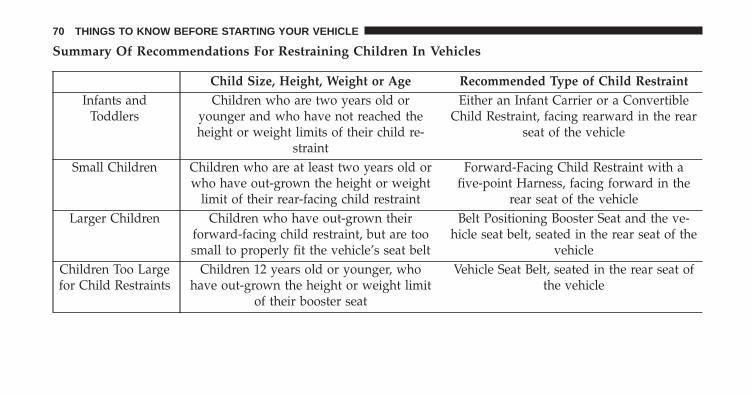
Summary Of Recommendations For Restraining Children In Vehicles
Child Size, Height, Weight or Age Recommended Type of Child RestraintInfants and
ToddlersChildren who are two years old or
younger and who have not reached theheight or weight limits of their child re-
straint
Either an Infant Carrier or a ConvertibleChild Restraint, facing rearward in the rear
seat of the vehicle
Small Children Children who are at least two years old orwho have out-grown the height or weight
limit of their rear-facing child restraint
Forward-Facing Child Restraint with afive-point Harness, facing forward in the
rear seat of the vehicleLarger Children Children who have out-grown their
forward-facing child restraint, but are toosmall to properly fit the vehicle’s seat belt
Belt Positioning Booster Seat and the ve-hicle seat belt, seated in the rear seat of the
vehicleChildren Too Largefor Child Restraints
Children 12 years old or younger, whohave out-grown the height or weight limit
of their booster seat
Vehicle Seat Belt, seated in the rear seat ofthe vehicle
70 THINGS TO KNOW BEFORE STARTING YOUR VEHICLE
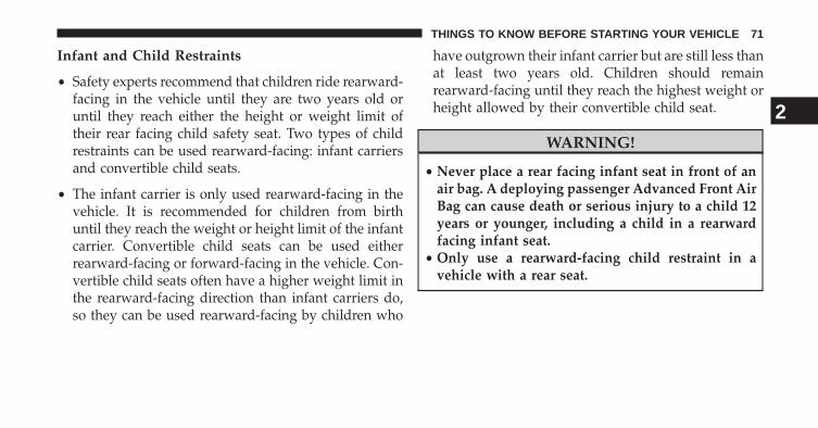
Infant and Child Restraints
• Safety experts recommend that children ride rearward-facing in the vehicle until they are two years old oruntil they reach either the height or weight limit oftheir rear facing child safety seat. Two types of childrestraints can be used rearward-facing: infant carriersand convertible child seats.
• The infant carrier is only used rearward-facing in thevehicle. It is recommended for children from birthuntil they reach the weight or height limit of the infantcarrier. Convertible child seats can be used eitherrearward-facing or forward-facing in the vehicle. Con-vertible child seats often have a higher weight limit inthe rearward-facing direction than infant carriers do,so they can be used rearward-facing by children who
have outgrown their infant carrier but are still less thanat least two years old. Children should remainrearward-facing until they reach the highest weight orheight allowed by their convertible child seat.
WARNING!
• Never place a rear facing infant seat in front of anair bag. A deploying passenger Advanced Front AirBag can cause death or serious injury to a child 12years or younger, including a child in a rearwardfacing infant seat.
• Only use a rearward-facing child restraint in avehicle with a rear seat.
2
THINGS TO KNOW BEFORE STARTING YOUR VEHICLE 71
Older Children and Child Restraints
Children who are two years old or who have outgrowntheir rear-facing convertible child seat can ride forward-facing in the vehicle. Forward-facing child seats andconvertible child seats used in the forward-facing direc-tion are for children who are over two years old or whohave outgrown the rear-facing weight or height limit oftheir rear-facing convertible child seat. Children shouldremain in a forward-facing child seat with a harness foras long as possible, up to the highest weight or heightallowed by the child seat.
All children whose weight or height is above theforward-facing limit for the child seat should use abelt-positioning booster seat until the vehicle’s seat beltsfit properly. If the child cannot sit with knees bent overthe vehicle’s seat cushion while the child’s back is againstthe seatback, they should use a belt-positioning booster
seat. The child and belt-positioning booster seat are heldin the vehicle by the seat belt.
WARNING!
• Improper installation can lead to failure of aninfant or child restraint. It could come loose in acollision. The child could be badly injured orkilled. Follow the child restraint manufacturer’sdirections exactly when installing an infant orchild restraint.
• When your child restraint is not in use, secure it inthe vehicle with the seat belt or tether anchorage, orremove it from the vehicle. Do not leave it loose inthe vehicle. In a sudden stop or accident, it couldstrike the occupants or seatbacks and cause seriouspersonal injury.
72 THINGS TO KNOW BEFORE STARTING YOUR VEHICLE
Children Too Large for Booster Seats
Children who are large enough to wear the shoulder beltcomfortably, and whose legs are long enough to bendover the front of the seat when their back is against theseatback, should use the seat belt in the seat. Use thissimple 5-step test to decide whether the child can use thevehicle’s seat belt alone:
• Can the child sit all the way back against the back ofthe vehicle seat?
• Do the child’s knees bend comfortably over the front ofthe vehicle seat – while they are still sitting all the wayback?
• Does the shoulder belt cross the child’s shoulderbetween their neck and arm?
• Is the lap part of the belt as low as possible, touchingthe child’s thighs and not their stomach?
• Can the child stay seated like this for the whole trip?
If the answer to any of these questions was “no,” then thechild still needs to use a booster seat in this vehicle. If thechild is using the lap/shoulder belt, check belt fit peri-odically. A child’s squirming or slouching can move thebelt out of position. If the shoulder belt contacts the faceor neck, move the child closer to the center of the vehicle.Never allow a child to put the shoulder belt under an armor behind their back.
WARNING!
Improper installation of a child restraint to the tetheranchorage can lead to failure of an infant or childrestraint. The child could be badly injured or killed.Follow the manufacturer’s directions exactly wheninstalling an infant or child restraint.
2
THINGS TO KNOW BEFORE STARTING YOUR VEHICLE 73
Installing Child Restraints Using The Vehicle Seatbelt
The passenger seat belt is equipped with an automaticlocking retractor for child restraint system installation. Itis designed to keep the lap portion the seat belt tightaround the child restraint (Refer to “Automatic LockingMode”).
Installing a Child Restraint with a Switchable AutomaticLocking Retractor (ALR):
1. Place the child seat in the center of the seatingposition.
2. Pull enough of the seat belt webbing from the retractorto pass it through the belt path of the child restraint.Do not twist the belt webbing in the belt path.
3. Slide the latch plate into the buckle until you hear a“click.”
4. Pull on the webbing to make the lap portion tightagainst the child seat.
5. To lock the seat belt, pull down on the shoulder part ofthe belt until you have pulled all the seat belt webbingout of the retractor. Then, allow the webbing to retractback into the retractor. As the webbing retracts, youwill hear a clicking sound. This means the seat belt isnow in the Automatic Locking mode.
6. Try to pull the webbing out of the retractor. If it islocked, you should not be able to pull out any web-bing. If the retractor is not locked, repeat step 5.
7. Finally, pull up on any excess webbing to tighten thelap portion around the child restraint while you pushthe child restraint rearward and downward into thevehicle seat.
74 THINGS TO KNOW BEFORE STARTING YOUR VEHICLE
8. If the child restraint has a top tether strap and theseating position has a top tether anchorage, connectthe tether strap to the anchorage and tighten the tetherstrap. See section �Child Restraint Tether Anchorage�for directions to attach a tether anchor.
9. Test that the child restraint is installed tightly bypulling back and forth on the child seat at the beltpath. It should not move more than 1 inch (25.4 mm)in any direction.
Any seat belt system will loosen with time, so check thebelt occasionally, and pull it tight if necessary.
Child Restraint Tether Anchorage
Always use the tether anchor when using theseat belt to install a forward facing child re-straint, up to the recommended weight limit ofthe child restraint. There is a tether strap an-
chor located behind the child tether access cover behindthe passenger seat to the anchor.
To attach a child restraint tether strap to the anchor:
1. Move the seat forward.
2. Move the seatback to its full forward position.
3. Remove the child tether access cover by prying eitherside with a screwdriver or similar tool, as shown.
2
THINGS TO KNOW BEFORE STARTING YOUR VEHICLE 75
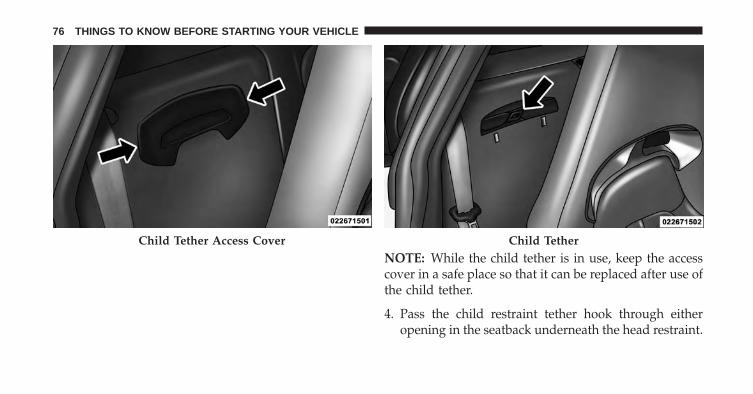
NOTE: While the child tether is in use, keep the accesscover in a safe place so that it can be replaced after use ofthe child tether.
4. Pass the child restraint tether hook through eitheropening in the seatback underneath the head restraint.
Child Tether Access Cover Child Tether
76 THINGS TO KNOW BEFORE STARTING YOUR VEHICLE
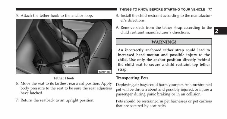
5. Attach the tether hook to the anchor loop.
6. Move the seat to its farthest rearward position. Applybody pressure to the seat to be sure the seat adjustershave latched.
7. Return the seatback to an upright position.
8. Install the child restraint according to the manufactur-er’s directions.
9. Remove slack from the tether strap according to thechild restraint manufacturer’s directions.
WARNING!
An incorrectly anchored tether strap could lead toincreased head motion and possible injury to thechild. Use only the anchor position directly behindthe child seat to secure a child restraint top tetherstrap.
Transporting Pets
Deploying air bags could harm your pet. An unrestrainedpet will be thrown about and possibly injured, or injure apassenger during panic braking or in an collision.
Pets should be restrained in pet harnesses or pet carriersthat are secured by seat belts.
Tether Hook
2
THINGS TO KNOW BEFORE STARTING YOUR VEHICLE 77
BREAK-IN RECOMMENDATIONS
A long break-in period is not required for the drivetrain(engine, transmission, and rear axle) in your new vehicle.Following these few simple guidelines is all that isnecessary for a good break-in.
For the first 500 miles (800 km):
• Keep your vehicle speed below the legal, posted speedlimit and your engine speed below 4,000 RPM.
• Avoid driving at a constant speed, either fast or slow,for long periods.
• Do not make any full throttle starts and avoid fullthrottle acceleration.
• Use the proper gear for your speed range.
• Wait until the engine has reached normal operatingtemperature before driving at the recommended maxi-mum break-in speed.
• Avoid excessive idling.
• Check the engine oil level at every fuel fill.
NOTE: A new engine will consume some oil during thefirst few thousand miles (kilometers) of operation. Thisshould be considered a normal part of the break-in andnot interpreted as a sign of difficulty.
SAFETY TIPS
Transporting Passengers
NEVER TRANSPORT PASSENGERS IN THE CARGOAREA.
WARNING!
• Do not leave children or animals inside parkedvehicles in hot weather. Interior heat build-up maycause serious injury or death.
(Continued)
78 THINGS TO KNOW BEFORE STARTING YOUR VEHICLE

WARNING! (Continued)• It is extremely dangerous to ride in a cargo area,
inside or outside of a vehicle. In a collision, peopleriding in these areas are more likely to be seriouslyinjured or killed.
• Do not allow people to ride in any area of yourvehicle that is not equipped with seats and seatbelts.
• Be sure everyone in your vehicle is in a seat andusing a seat belt properly.
Exhaust Gas
WARNING!
Exhaust gases can injure or kill. They contain carbonmonoxide (CO), which is colorless and odorless.Breathing it can make you unconscious and can
(Continued)
WARNING! (Continued)eventually poison you. To avoid breathing (CO),follow these safety tips:• Do not run the engine in a closed garage or in
confined areas any longer than needed to moveyour vehicle in or out of the area.
• If you are required to drive with the trunk/liftgate/rear doors open, make sure that all windows areclosed and the climate control BLOWER switch isset at high speed. DO NOT use the recirculationmode.
• If it is necessary to sit in a parked vehicle with theengine running, adjust your heating or coolingcontrols to force outside air into the vehicle. Set theblower at high speed.
The best protection against carbon monoxide entry intothe vehicle body is a properly maintained engine exhaustsystem.
2
THINGS TO KNOW BEFORE STARTING YOUR VEHICLE 79
Whenever a change is noticed in the sound of the exhaustsystem, when exhaust fumes can be detected inside thevehicle, or when the underside or rear of the vehicle isdamaged, have a competent mechanic inspect the com-plete exhaust system and adjacent body areas for broken,damaged, deteriorated, or mispositioned parts. Openseams or loose connections could permit exhaust fumesto seep into the passenger compartment. In addition,inspect the exhaust system each time the vehicle is raisedfor lubrication or oil change. Replace as required.
Safety Checks You Should Make Inside TheVehicle
Seat Belts
Inspect the belt system periodically, checking for cuts,frays, and loose parts. Damaged parts must be replacedimmediately. Do not disassemble or modify the system.
Front seat belt assemblies must be replaced after acollision. Seat belt assemblies must be replaced after acollision if they have been damaged (i.e., bent retractor,torn webbing, etc.). If there is any question regarding beltor retractor condition, replace the belt.
Air Bag Warning Light
The light should come on and remain on for four to eightseconds as a bulb check when the ignition is first cycledto ON. If the light is not lit during starting, see yourauthorized dealer. If the light stays on, flickers, or comeson while driving, have the system checked by an autho-rized dealer.
Defroster
Check operation by selecting the defrost mode and placethe blower control on high speed. You should be able to feelthe air directed against the windshield. See your autho-rized dealer for service if your defroster is inoperable.
80 THINGS TO KNOW BEFORE STARTING YOUR VEHICLE
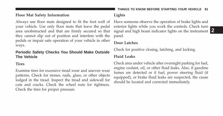
Floor Mat Safety Information
Always use floor mats designed to fit the foot well ofyour vehicle. Use only floor mats that leave the pedalarea unobstructed and that are firmly secured so thatthey cannot slip out of position and interfere with thepedals or impair safe operation of your vehicle in otherways.
Periodic Safety Checks You Should Make OutsideThe Vehicle
Tires
Examine tires for excessive tread wear and uneven wearpatterns. Check for stones, nails, glass, or other objectslodged in the tread. Inspect the tread and sidewall forcuts and cracks. Check the wheel nuts for tightness.Check the tires for proper pressure.
Lights
Have someone observe the operation of brake lights andexterior lights while you work the controls. Check turnsignal and high beam indicator lights on the instrumentpanel.
Door Latches
Check for positive closing, latching, and locking.
Fluid Leaks
Check area under vehicle after overnight parking for fuel,engine coolant, oil, or other fluid leaks. Also, if gasolinefumes are detected or if fuel, power steering fluid (ifequipped), or brake fluid leaks are suspected, the causeshould be located and corrected immediately.
2
THINGS TO KNOW BEFORE STARTING YOUR VEHICLE 81

UNDERSTANDING THE FEATURES OF YOUR VEHICLE
CONTENTS� MIRRORS . . . . . . . . . . . . . . . . . . . . . . . . . . . . .86
▫ Automatic Dimming Mirror . . . . . . . . . . . . . .86
▫ Outside Mirrors . . . . . . . . . . . . . . . . . . . . . . .88
▫ Power Mirrors . . . . . . . . . . . . . . . . . . . . . . . .88
▫ Vanity Mirror . . . . . . . . . . . . . . . . . . . . . . . . .89
� SEATS . . . . . . . . . . . . . . . . . . . . . . . . . . . . . . .90
▫ Manual Seats . . . . . . . . . . . . . . . . . . . . . . . . .90
▫ Power Seats . . . . . . . . . . . . . . . . . . . . . . . . . .93
▫ Non-Adjustable Head Restraints . . . . . . . . . . .96
� TO OPEN AND CLOSE THE HOOD . . . . . . . . .96
� LIGHTS . . . . . . . . . . . . . . . . . . . . . . . . . . . . . .98
▫ Headlight Switch . . . . . . . . . . . . . . . . . . . . . .98
▫ Automatic Headlights . . . . . . . . . . . . . . . . . . .99
▫ Headlights On With Wipers (Available withAutomatic Headlights Only) . . . . . . . . . . . . .100
▫ Headlight Time Delay . . . . . . . . . . . . . . . . . .100
▫ Daytime Running Lights . . . . . . . . . . . . . . . .101
▫ Lights-On Reminder . . . . . . . . . . . . . . . . . . .101
▫ Multifunction Lever . . . . . . . . . . . . . . . . . . .101
▫ Turn Signals . . . . . . . . . . . . . . . . . . . . . . . . .102
3
▫ High/Low Beam Switch . . . . . . . . . . . . . . . .102
▫ Flash-To-Pass . . . . . . . . . . . . . . . . . . . . . . . .102
▫ Interior Lights . . . . . . . . . . . . . . . . . . . . . . .103
� WINDSHIELD WIPERS AND WASHERS . . . . . .105
▫ Intermittent Wiper System . . . . . . . . . . . . . . .105
▫ Wiper Operation . . . . . . . . . . . . . . . . . . . . . .105
▫ Mist Feature . . . . . . . . . . . . . . . . . . . . . . . . .106
▫ Windshield Washers . . . . . . . . . . . . . . . . . . .106
▫ Headlights On With Wipers (Available withAutomatic Headlights Only) . . . . . . . . . . . . .107
� TILT STEERING COLUMN . . . . . . . . . . . . . . .107
� ADJUSTABLE PEDALS . . . . . . . . . . . . . . . . . .108
▫ Adjustable Foot Rest . . . . . . . . . . . . . . . . . . .110
� ELECTRONIC SPEED CONTROL . . . . . . . . . . .110
▫ To Activate . . . . . . . . . . . . . . . . . . . . . . . . . .111
▫ To Set A Desired Speed . . . . . . . . . . . . . . . . .112
▫ To Deactivate. . . . . . . . . . . . . . . . . . . . . . . . .112
▫ To Resume Speed. . . . . . . . . . . . . . . . . . . . . .112
▫ To Vary The Speed Setting . . . . . . . . . . . . . . .112
▫ To Accelerate For Passing . . . . . . . . . . . . . . . .113
� PARKVIEW® REAR BACK UP CAMERA — IFEQUIPPED . . . . . . . . . . . . . . . . . . . . . . . . . . .114
▫ Turning ParkView® On Or Off — WithTouch—Screen Radio . . . . . . . . . . . . . . . . . . .115
� GARAGE DOOR OPENER — IF EQUIPPED . . .116
▫ Before You Begin Programming HomeLink® . .117
▫ Programming A Rolling Code . . . . . . . . . . . . .117
84 UNDERSTANDING THE FEATURES OF YOUR VEHICLE
▫ Programming A Non-Rolling Code . . . . . . . . .120
▫ Canadian/Gate Operator Programming . . . . . .121
▫ Using HomeLink®. . . . . . . . . . . . . . . . . . . . .122
▫ Security . . . . . . . . . . . . . . . . . . . . . . . . . . . .122
▫ Troubleshooting Tips . . . . . . . . . . . . . . . . . . .123
▫ General Information. . . . . . . . . . . . . . . . . . . .124
� ELECTRICAL POWER OUTLETS . . . . . . . . . . .124
� CUPHOLDERS — If Equipped . . . . . . . . . . . . .127
� STORAGE . . . . . . . . . . . . . . . . . . . . . . . . . . . .127
▫ Glovebox Storage. . . . . . . . . . . . . . . . . . . . . .127
▫ Console Features . . . . . . . . . . . . . . . . . . . . . .128
▫ Door Storage . . . . . . . . . . . . . . . . . . . . . . . . .130
� REAR WINDOW FEATURES . . . . . . . . . . . . . .131
▫ Rear Window Defroster . . . . . . . . . . . . . . . . .131
3
UNDERSTANDING THE FEATURES OF YOUR VEHICLE 85
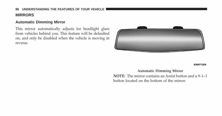
MIRRORS
Automatic Dimming Mirror
This mirror automatically adjusts for headlight glarefrom vehicles behind you. This feature will be defaultedon, and only be disabled when the vehicle is moving inreverse.
NOTE: The mirror contains an Assist button and a 9–1–1button located on the bottom of the mirror.
Automatic Dimming Mirror
86 UNDERSTANDING THE FEATURES OF YOUR VEHICLE
Assist Call
The rear view mirror contains an ASSIST push buttonwhich automatically connects the vehicle occupants toone of several predefined locations for immediate sup-port:
• Roadside Assistance – If you get a flat tire, or need atow, just press the Assist button and you’ll be con-nected to someone who can help. Roadside Assistancewill know what vehicle you’re driving and its location.Additional fees may apply for roadside Assistance.
• Uconnect® Access Customer Care – In-vehicle supportfor Uconnect® Access and Uconnect® Access via Mo-bile features.
• Vehicle Customer Care – Total support for all othervehicle issues.
9-1-1 Call
Report an accident without taking your eyes off the road.Just press 9-1-1 on your mirror and connect.
CAUTION!
To avoid damage to the mirror during cleaning, neverspray any cleaning solution directly onto the mirror.Apply the solution onto a clean cloth and wipe themirror clean.
3
UNDERSTANDING THE FEATURES OF YOUR VEHICLE 87
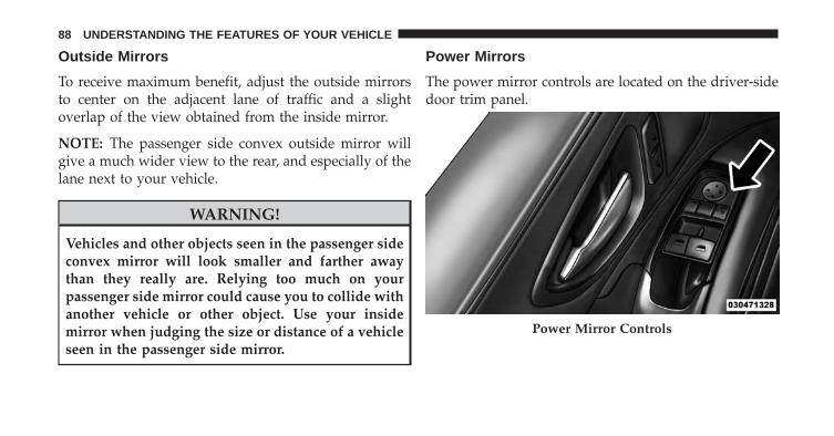
Outside Mirrors
To receive maximum benefit, adjust the outside mirrorsto center on the adjacent lane of traffic and a slightoverlap of the view obtained from the inside mirror.
NOTE: The passenger side convex outside mirror willgive a much wider view to the rear, and especially of thelane next to your vehicle.
WARNING!
Vehicles and other objects seen in the passenger sideconvex mirror will look smaller and farther awaythan they really are. Relying too much on yourpassenger side mirror could cause you to collide withanother vehicle or other object. Use your insidemirror when judging the size or distance of a vehicleseen in the passenger side mirror.
Power Mirrors
The power mirror controls are located on the driver-sidedoor trim panel.
Power Mirror Controls
88 UNDERSTANDING THE FEATURES OF YOUR VEHICLE
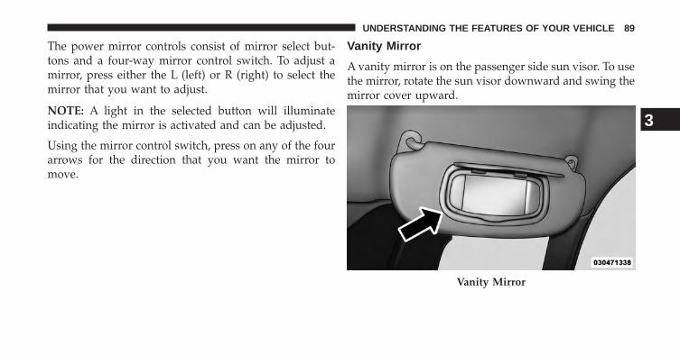
The power mirror controls consist of mirror select but-tons and a four-way mirror control switch. To adjust amirror, press either the L (left) or R (right) to select themirror that you want to adjust.
NOTE: A light in the selected button will illuminateindicating the mirror is activated and can be adjusted.
Using the mirror control switch, press on any of the fourarrows for the direction that you want the mirror tomove.
Vanity Mirror
A vanity mirror is on the passenger side sun visor. To usethe mirror, rotate the sun visor downward and swing themirror cover upward.
Vanity Mirror
3
UNDERSTANDING THE FEATURES OF YOUR VEHICLE 89
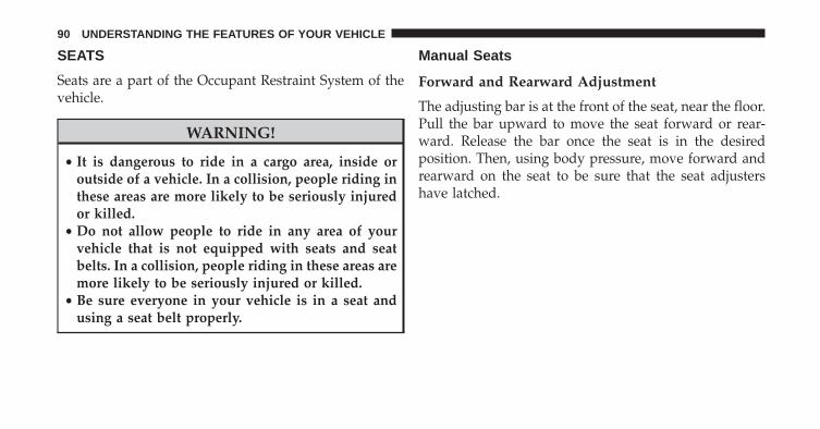
SEATS
Seats are a part of the Occupant Restraint System of thevehicle.
WARNING!
• It is dangerous to ride in a cargo area, inside oroutside of a vehicle. In a collision, people riding inthese areas are more likely to be seriously injuredor killed.
• Do not allow people to ride in any area of yourvehicle that is not equipped with seats and seatbelts. In a collision, people riding in these areas aremore likely to be seriously injured or killed.
• Be sure everyone in your vehicle is in a seat andusing a seat belt properly.
Manual Seats
Forward and Rearward Adjustment
The adjusting bar is at the front of the seat, near the floor.Pull the bar upward to move the seat forward or rear-ward. Release the bar once the seat is in the desiredposition. Then, using body pressure, move forward andrearward on the seat to be sure that the seat adjustershave latched.
90 UNDERSTANDING THE FEATURES OF YOUR VEHICLE
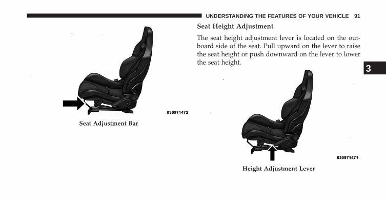
Seat Height Adjustment
The seat height adjustment lever is located on the out-board side of the seat. Pull upward on the lever to raisethe seat height or push downward on the lever to lowerthe seat height.
Seat Adjustment Bar
Height Adjustment Lever
3
UNDERSTANDING THE FEATURES OF YOUR VEHICLE 91
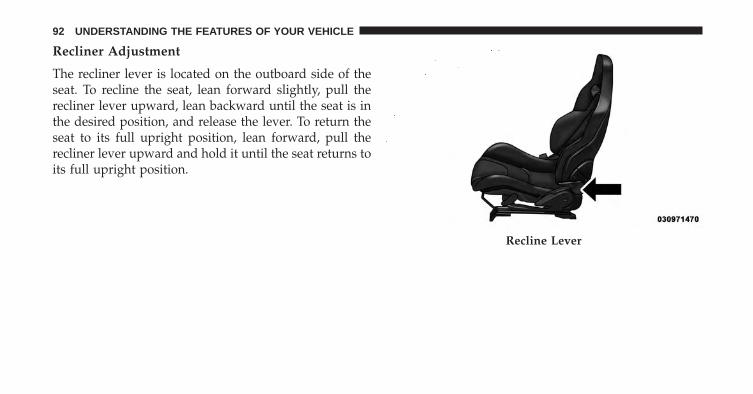
Recliner Adjustment
The recliner lever is located on the outboard side of theseat. To recline the seat, lean forward slightly, pull therecliner lever upward, lean backward until the seat is inthe desired position, and release the lever. To return theseat to its full upright position, lean forward, pull therecliner lever upward and hold it until the seat returns toits full upright position.
Recline Lever
92 UNDERSTANDING THE FEATURES OF YOUR VEHICLE

WARNING!
• Adjusting a seat while driving may be dangerous.Moving a seat while driving could result in loss ofcontrol which could cause a collision and seriousinjury or death.
• Seats should be adjusted before fastening the seatbelts and while the vehicle is parked. Seriousinjury or death could result from a poorly adjustedseat belt.
• Do not ride with the seatback reclined so that theshoulder belt is no longer resting against yourchest. In a collision you could slide under the seatbelt, which could result in serious injury or death.
Power Seats
On models equipped with power seats, the power seatswitch is located on the outboard side of the seat near thefloor.
Power Seat Switch
3
UNDERSTANDING THE FEATURES OF YOUR VEHICLE 93
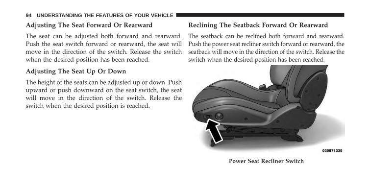
Adjusting The Seat Forward Or Rearward
The seat can be adjusted both forward and rearward.Push the seat switch forward or rearward, the seat willmove in the direction of the switch. Release the switchwhen the desired position has been reached.
Adjusting The Seat Up Or Down
The height of the seats can be adjusted up or down. Pushupward or push downward on the seat switch, the seatwill move in the direction of the switch. Release theswitch when the desired position is reached.
Reclining The Seatback Forward Or Rearward
The seatback can be reclined both forward and rearward.Push the power seat recliner switch forward or rearward, theseatback will move in the direction of the switch. Release theswitch when the desired position has been reached.
Power Seat Recliner Switch
94 UNDERSTANDING THE FEATURES OF YOUR VEHICLE
WARNING!
• Adjusting a seat while driving may be dangerous.Moving a seat while driving could result in loss ofcontrol which could cause a collision and seriousinjury or death.
• Seats should be adjusted before fastening the seatbelts and while the vehicle is parked. Seriousinjury or death could result from a poorly adjustedseat belt.
• Do not ride with the seatback reclined so that theshoulder belt is no longer resting against your chest.In a collision you could slide under the seat belt,which could result in serious injury or death.
CAUTION!
Do not place any article under a power seat orimpede its ability to move as it may cause damage tothe seat controls. Seat travel may become limited ifmovement is stopped by an obstruction in the seat’spath.
3
UNDERSTANDING THE FEATURES OF YOUR VEHICLE 95
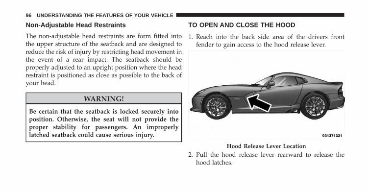
Non-Adjustable Head Restraints
The non-adjustable head restraints are form fitted intothe upper structure of the seatback and are designed toreduce the risk of injury by restricting head movement inthe event of a rear impact. The seatback should beproperly adjusted to an upright position where the headrestraint is positioned as close as possible to the back ofyour head.
WARNING!
Be certain that the seatback is locked securely intoposition. Otherwise, the seat will not provide theproper stability for passengers. An improperlylatched seatback could cause serious injury.
TO OPEN AND CLOSE THE HOOD
1. Reach into the back side area of the drivers frontfender to gain access to the hood release lever.
2. Pull the hood release lever rearward to release thehood latches.
Hood Release Lever Location
96 UNDERSTANDING THE FEATURES OF YOUR VEHICLE
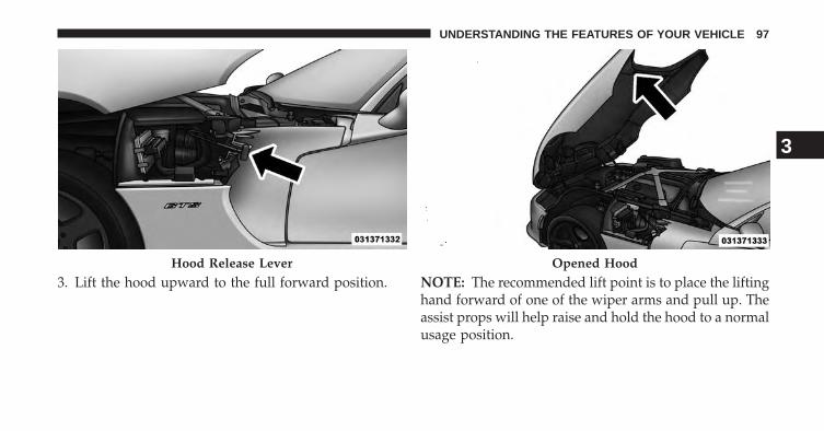
3. Lift the hood upward to the full forward position. NOTE: The recommended lift point is to place the liftinghand forward of one of the wiper arms and pull up. Theassist props will help raise and hold the hood to a normalusage position.
Hood Release Lever Opened Hood
3
UNDERSTANDING THE FEATURES OF YOUR VEHICLE 97
CAUTION!
• Do not leave the hood open in areas where stronggust of wind are likely. Such a place might be bythe side of the road where large trucks pass by.Strong gusts of wind may damage the hood. Al-ways close the hood in such situations.
• To prevent possible damage, do not slam the hoodto close it. Simply lower the hood until it is openapproximately 18 in (30 cm) and then drop it. Thisshould secure both latches. If both latches did notsecure, a slight push effort in the same area usedfor opening the hood (front of wiper arm) needs tobe applied to secure the latches. Never drive thevehicle unless the hood is fully closed with bothlatches engaged.
WARNING!
Be sure the hood is fully latched before driving yourvehicle. If the hood is not fully latched, it could openwhen the vehicle is in motion and block your vision.Failure to follow this warning could result in seriousinjury or death.
LIGHTS
Headlight Switch
The headlight switch is located on the left side ofthe instrument panel. This switch controls theoperation of the headlights, parking lights, instru-
ment panel lights, instrument panel light dimming andinterior lights.
98 UNDERSTANDING THE FEATURES OF YOUR VEHICLE
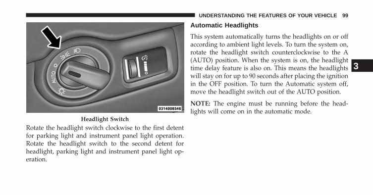
Rotate the headlight switch clockwise to the first detentfor parking light and instrument panel light operation.Rotate the headlight switch to the second detent forheadlight, parking light and instrument panel light op-eration.
Automatic Headlights
This system automatically turns the headlights on or offaccording to ambient light levels. To turn the system on,rotate the headlight switch counterclockwise to the A(AUTO) position. When the system is on, the headlighttime delay feature is also on. This means the headlightswill stay on for up to 90 seconds after placing the ignitionin the OFF position. To turn the Automatic system off,move the headlight switch out of the AUTO position.
NOTE: The engine must be running before the head-lights will come on in the automatic mode.
Headlight Switch
3
UNDERSTANDING THE FEATURES OF YOUR VEHICLE 99
Headlights On With Wipers (Available withAutomatic Headlights Only)
When this feature is active, the headlights will turn onapproximately 10 seconds after the wipers are turned onif the headlight switch is placed in the AUTO position. Inaddition, the headlights will turn off when the wipers areturned off if they were turned on by this feature.
NOTE: The Headlights On with Wipers feature can beturned on or off using the Uconnect® System, refer to“Uconnect® Settings” in “Understanding Your Instru-ment Panel” for further information.
Headlight Time Delay
This feature provides the safety of headlight illuminationfor up to 90 seconds (programmable) when leaving yourvehicle in an unlit area.
To activate the delay feature, place the ignition in the OFFposition while the headlights are still on. Then, turn off
the headlights within 45 seconds. The delay intervalbegins when the headlight switch is turned off.
If you turn the headlights or parking lights on, or placethe ignition in ACC or RUN, the system will cancel thedelay.
If you turn the headlights off before the ignition, they willturn off in the normal manner.
NOTE:
• The lights must be turned off within 45 seconds ofplacing the ignition in the OFF position to activate thisfeature.
• The headlight delay time is programmable using theUconnect® System, refer to “Uconnect® Settings” in“Understanding Your Instrument Panel” for furtherinformation.
100 UNDERSTANDING THE FEATURES OF YOUR VEHICLE
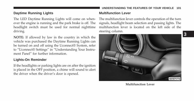
Daytime Running Lights
The LED Daytime Running Lights will come on when-ever the engine is running and the park brake is off. Theheadlight switch must be used for normal nighttimedriving.
NOTE: If allowed by law in the country in which thevehicle was purchased the Daytime Running Lights canbe turned on and off using the Uconnect® System, referto “Uconnect® Settings” in “Understanding Your Instru-ment Panel” for further information.
Lights-On Reminder
If the headlights or parking lights are on after the ignitionis placed in the OFF position, a chime will sound to alertthe driver when the driver’s door is opened.
Multifunction Lever
The multifunction lever controls the operation of the turnsignals, headlight beam selection and passing lights. Themultifunction lever is located on the left side of thesteering column.
Multifunction Lever
3
UNDERSTANDING THE FEATURES OF YOUR VEHICLE 101
Turn Signals
Move the multifunction lever up or down and the arrowson each side of the instrument cluster flash to showproper operation of the front and rear turn signal lights.
NOTE:
• If either light remains on and does not flash, or there isa very fast flash rate, check for a defective outside lightbulb. If an indicator fails to light when the lever ismoved, it would suggest that the indicator bulb isdefective.
• A “Turn Signal On” message will appear in the EVIC(if equipped) and a continuous chime will sound if thevehicle is driven more than 1 mile (1.6 km) with eitherturn signal on.
High/Low Beam Switch
Push the multifunction lever away from you to switchthe headlights to high beam. Pull the multifunction levertoward you to switch the headlights back to low beam.
Flash-To-Pass
You can signal another vehicle with your headlights bylightly pulling the multifunction lever toward you. Thiswill turn on the high beams headlights until the lever isreleased.
102 UNDERSTANDING THE FEATURES OF YOUR VEHICLE
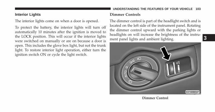
Interior Lights
The interior lights come on when a door is opened.
To protect the battery, the interior lights will turn offautomatically 10 minutes after the ignition is moved tothe LOCK position. This will occur if the interior lightswere switched on manually or are on because a door isopen. This includes the glove box light, but not the trunklight. To restore interior light operation, either turn theignition switch ON or cycle the light switch.
Dimmer Controls
The dimmer control is part of the headlight switch and islocated on the left side of the instrument panel. Rotatingthe dimmer control upward with the parking lights orheadlights on will increase the brightness of the instru-ment panel lights and ambient lighting.
Dimmer Control
3
UNDERSTANDING THE FEATURES OF YOUR VEHICLE 103
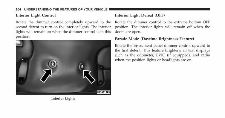
Interior Light Control
Rotate the dimmer control completely upward to thesecond detent to turn on the interior lights. The interiorlights will remain on when the dimmer control is in thisposition.
Interior Light Defeat (OFF)
Rotate the dimmer control to the extreme bottom OFFposition. The interior lights will remain off when thedoors are open.
Parade Mode (Daytime Brightness Feature)
Rotate the instrument panel dimmer control upward tothe first detent. This feature brightens all text displayssuch as the odometer, EVIC (if equipped), and radiowhen the position lights or headlights are on.
Interior Lights
104 UNDERSTANDING THE FEATURES OF YOUR VEHICLE
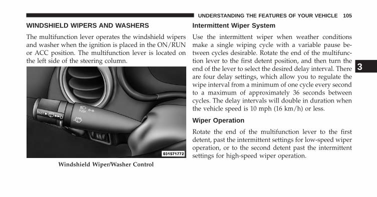
WINDSHIELD WIPERS AND WASHERS
The multifunction lever operates the windshield wipersand washer when the ignition is placed in the ON/RUNor ACC position. The multifunction lever is located onthe left side of the steering column.
Intermittent Wiper System
Use the intermittent wiper when weather conditionsmake a single wiping cycle with a variable pause be-tween cycles desirable. Rotate the end of the multifunc-tion lever to the first detent position, and then turn theend of the lever to select the desired delay interval. Thereare four delay settings, which allow you to regulate thewipe interval from a minimum of one cycle every secondto a maximum of approximately 36 seconds betweencycles. The delay intervals will double in duration whenthe vehicle speed is 10 mph (16 km/h) or less.
Wiper Operation
Rotate the end of the multifunction lever to the firstdetent, past the intermittent settings for low-speed wiperoperation, or to the second detent past the intermittentsettings for high-speed wiper operation.
Windshield Wiper/Washer Control
3
UNDERSTANDING THE FEATURES OF YOUR VEHICLE 105
CAUTION!
• Turn the windshield wipers off when drivingthrough an automatic car wash. Damage to thewindshield wipers may result if the wiper controlis left in any position other than off.
• In cold weather, always turn off the wiper switchand allow the wipers to return to the “Park” posi-tion before turning off the engine. If the wiperswitch is left on and the wipers freeze to thewindshield, damage to the wiper motor may occurwhen the vehicle is restarted.
• Always remove any buildup of snow that preventsthe windshield wiper blades from returning to theoff position. If the windshield wiper control isturned off and the blades cannot return to the offposition, damage to the wiper motor may occur.
Mist Feature
When a single wipe to clear off road mist or spray froma passing vehicle is needed, push the washer knob,located on the end of the multifunction lever, inward tothe first detent and release. The wipers will cycle onetime and automatically shut off.
NOTE: The mist feature does not activate the washerpump; therefore, no washer fluid will be sprayed on thewindshield. The wash function must be used in order tospray the windshield with washer fluid.
Windshield Washers
To use the windshield washer, push the washer knob,located on the end of the multifunction lever, inward tothe second detent. Washer fluid will be sprayed and thewiper will operate for two to three cycles after the washerknob is released from this position. If the washer knob isdepressed while in the delay range, the wiper willoperate for several seconds after the washer knob is
106 UNDERSTANDING THE FEATURES OF YOUR VEHICLE
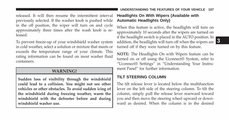
released. It will then resume the intermittent intervalpreviously selected. If the washer knob is pushed whilein the off position, the wiper will turn on and cycleapproximately three times after the wash knob is re-leased.
To prevent freeze-up of your windshield washer systemin cold weather, select a solution or mixture that meets orexceeds the temperature range of your climate. Thisrating information can be found on most washer fluidcontainers.
WARNING!
Sudden loss of visibility through the windshieldcould lead to a collision. You might not see othervehicles or other obstacles. To avoid sudden icing ofthe windshield during freezing weather, warm thewindshield with the defroster before and duringwindshield washer use.
Headlights On With Wipers (Available withAutomatic Headlights Only)
When this feature is active, the headlights will turn onapproximately 10 seconds after the wipers are turned onif the headlight switch is placed in the AUTO position. Inaddition, the headlights will turn off when the wipers areturned off if they were turned on by this feature.
NOTE: The Headlights On with Wipers feature can beturned on or off using the Uconnect® System, refer to“Uconnect® Settings” in “Understanding Your Instru-ment Panel” for further information.
TILT STEERING COLUMN
The tilt release lever is located below the multifunctionlever on the left side of the steering column. To tilt thecolumn, simply pull the release lever rearward towardyou and then move the steering wheel upward or down-ward as desired. When the column is in the desired
3
UNDERSTANDING THE FEATURES OF YOUR VEHICLE 107
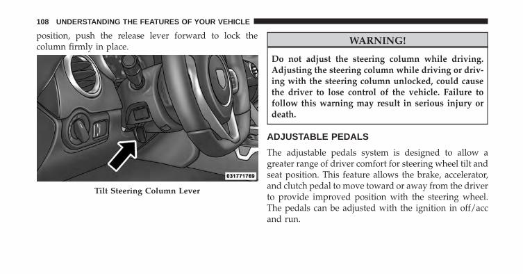
position, push the release lever forward to lock thecolumn firmly in place.
WARNING!
Do not adjust the steering column while driving.Adjusting the steering column while driving or driv-ing with the steering column unlocked, could causethe driver to lose control of the vehicle. Failure tofollow this warning may result in serious injury ordeath.
ADJUSTABLE PEDALS
The adjustable pedals system is designed to allow agreater range of driver comfort for steering wheel tilt andseat position. This feature allows the brake, accelerator,and clutch pedal to move toward or away from the driverto provide improved position with the steering wheel.The pedals can be adjusted with the ignition in off/accand run.
Tilt Steering Column Lever
108 UNDERSTANDING THE FEATURES OF YOUR VEHICLE
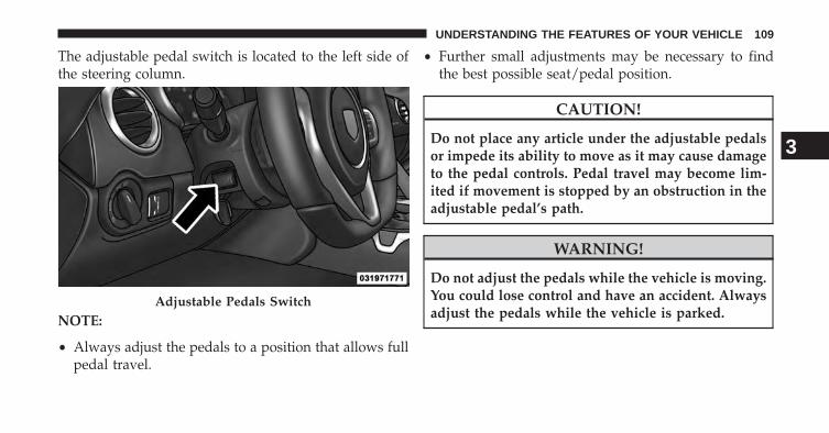
The adjustable pedal switch is located to the left side ofthe steering column.
NOTE:
• Always adjust the pedals to a position that allows fullpedal travel.
• Further small adjustments may be necessary to findthe best possible seat/pedal position.
CAUTION!
Do not place any article under the adjustable pedalsor impede its ability to move as it may cause damageto the pedal controls. Pedal travel may become lim-ited if movement is stopped by an obstruction in theadjustable pedal’s path.
WARNING!
Do not adjust the pedals while the vehicle is moving.You could lose control and have an accident. Alwaysadjust the pedals while the vehicle is parked.
Adjustable Pedals Switch
3
UNDERSTANDING THE FEATURES OF YOUR VEHICLE 109
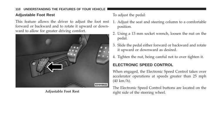
Adjustable Foot Rest
This feature allows the driver to adjust the foot restforward or backward and to rotate it upward or down-ward to allow for greater driving comfort.
To adjust the pedal:
1. Adjust the seat and steering column to a comfortableposition.
2. Using a 13 mm socket wrench, loosen the nut on thepedal.
3. Slide the pedal either forward or backward and rotateit upward or downward as desired.
4. Tighten the nut, being careful not to over tighten it.
ELECTRONIC SPEED CONTROL
When engaged, the Electronic Speed Control takes overaccelerator operations at speeds greater than 25 mph(40 km/h).
The Electronic Speed Control buttons are located on theright side of the steering wheel.Adjustable Foot Rest
110 UNDERSTANDING THE FEATURES OF YOUR VEHICLE
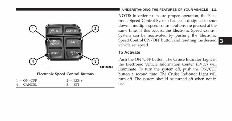
NOTE: In order to ensure proper operation, the Elec-tronic Speed Control System has been designed to shutdown if multiple speed control buttons are pressed at thesame time. If this occurs, the Electronic Speed ControlSystem can be reactivated by pushing the ElectronicSpeed Control ON/OFF button and resetting the desiredvehicle set speed.
To Activate
Push the ON/OFF button. The Cruise Indicator Light inthe Electronic Vehicle Information Center (EVIC) willilluminate. To turn the system off, push the ON/OFFbutton a second time. The Cruise Indicator Light willturn off. The system should be turned off when not inuse.
Electronic Speed Control Buttons
1 — ON/OFF 2 — RES +4 — CANCEL 3 — SET -
3
UNDERSTANDING THE FEATURES OF YOUR VEHICLE 111
WARNING!
Leaving the Electronic Speed Control system onwhen not in use is dangerous. You could accidentallyset the system or cause it to go faster than you want.You could lose control and have an accident. Alwaysleave the system OFF when you are not using it.
To Set A Desired Speed
Turn the Electronic Speed Control ON. When the vehiclehas reached the desired speed, press the SET (-) buttonand release. Release the accelerator and the vehicle willoperate at the selected speed.
NOTE: The vehicle should be traveling at a steady speedand on level ground before pressing the SET (-) button.
To Deactivate
A soft tap on the brake pedal, pushing the CANCELbutton, or normal brake pressure while slowing thevehicle will deactivate Electronic Speed Control withouterasing the set speed memory. Pressing the ON/OFFbutton or turning the ignition switch OFF erases the setspeed memory.
To Resume Speed
To resume a previously set speed, push the RES (+)button and release. Resume can be used at any speedabove 20 mph (32 km/h).
To Vary The Speed Setting
When the Electronic Speed Control is set, you can in-crease speed by pushing the RES (+) button. If the buttonis continually pressed, the set speed will continue toincrease until the button is released, then the new setspeed will be established.
112 UNDERSTANDING THE FEATURES OF YOUR VEHICLE
Pressing the RES (+) button once will result in a 1 mph(1.0 km/h) increase in set speed. Each subsequent tap ofthe button results in an increase of 1 mph (1.0 km/h).
To decrease speed while the Electronic Speed Control isset, push the SET (-) button. If the button is continuallyheld in the SET (-) position, the set speed will continue todecrease until the button is released. Release the buttonwhen the desired speed is reached, and the new set speedwill be established.
Pressing the SET (-) button once will result in a 1 mph(1.0 km/h) decrease in set speed. Each subsequent tap ofthe button results in a decrease of 1 mph (1.0 km/h).
NOTE: Tap results of 1 mph or 1 km/h depends onselection of US or METRIC units in the EVIC displaysettings menu, or the RADIO settings menu (dependenton vehicle configuration).
To Accelerate For Passing
Press the accelerator as you would normally. When thepedal is released, the vehicle will return to the set speed.
Using Electronic Speed Control On Hills
NOTE: The Electronic Speed Control system maintainsspeed up and down hills. A slight speed change onmoderate hills is normal.
On steep hills, a greater speed loss or gain may occur soit may be preferable to drive without Electronic SpeedControl.
WARNING!
Electronic Speed Control can be dangerous where thesystem cannot maintain a constant speed. Your ve-hicle could go too fast for the conditions, and you
(Continued)
3
UNDERSTANDING THE FEATURES OF YOUR VEHICLE 113
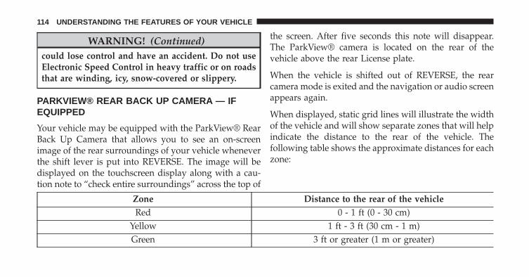
WARNING! (Continued)could lose control and have an accident. Do not useElectronic Speed Control in heavy traffic or on roadsthat are winding, icy, snow-covered or slippery.
PARKVIEW® REAR BACK UP CAMERA — IFEQUIPPED
Your vehicle may be equipped with the ParkView® RearBack Up Camera that allows you to see an on-screenimage of the rear surroundings of your vehicle wheneverthe shift lever is put into REVERSE. The image will bedisplayed on the touchscreen display along with a cau-tion note to “check entire surroundings” across the top of
the screen. After five seconds this note will disappear.The ParkView® camera is located on the rear of thevehicle above the rear License plate.
When the vehicle is shifted out of REVERSE, the rearcamera mode is exited and the navigation or audio screenappears again.
When displayed, static grid lines will illustrate the widthof the vehicle and will show separate zones that will helpindicate the distance to the rear of the vehicle. Thefollowing table shows the approximate distances for eachzone:
Zone Distance to the rear of the vehicleRed 0 - 1 ft (0 - 30 cm)
Yellow 1 ft - 3 ft (30 cm - 1 m)Green 3 ft or greater (1 m or greater)
114 UNDERSTANDING THE FEATURES OF YOUR VEHICLE
WARNING!
Drivers must be careful when backing up even whenusing the ParkView® Rear Back Up Camera. Alwayscheck carefully behind your vehicle, and be sure tocheck for pedestrians, animals, other vehicles, ob-structions, or blind spots before backing up. You areresponsible for the safety of your surroundings andmust continue to pay attention while backing up.Failure to do so can result in serious injury or death.
CAUTION!
• To avoid vehicle damage, ParkView® should onlybe used as a parking aid. The ParkView® camera isunable to view every obstacle or object in yourdrive path.
(Continued)
CAUTION! (Continued)• To avoid vehicle damage, the vehicle must be
driven slowly when using ParkView® to be able tostop in time when an obstacle is seen. It is recom-mended that the driver look frequently over his/hershoulder when using ParkView®.
NOTE: If snow, ice, mud, or any foreign substancebuilds up on the camera lens, clean the lens, rinse withwater, and dry with a soft cloth. Do not cover the lens.
Turning ParkView® On Or Off — WithTouch—Screen Radio
1. Turn the Radio on.
2. Press the “More” soft-key.
3. Press the “Settings” soft-key.
3
UNDERSTANDING THE FEATURES OF YOUR VEHICLE 115
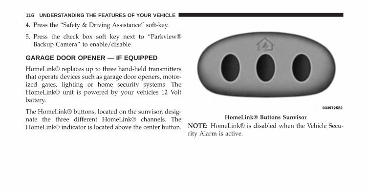
4. Press the “Safety & Driving Assistance” soft-key.
5. Press the check box soft key next to “Parkview®Backup Camera” to enable/disable.
GARAGE DOOR OPENER — IF EQUIPPED
HomeLink® replaces up to three hand-held transmittersthat operate devices such as garage door openers, motor-ized gates, lighting or home security systems. TheHomeLink® unit is powered by your vehicles 12 Voltbattery.
The HomeLink® buttons, located on the sunvisor, desig-nate the three different HomeLink® channels. TheHomeLink® indicator is located above the center button. NOTE: HomeLink® is disabled when the Vehicle Secu-
rity Alarm is active.
HomeLink® Buttons Sunvisor
116 UNDERSTANDING THE FEATURES OF YOUR VEHICLE
Before You Begin Programming HomeLink®
Be sure that your vehicle is parked outside of the garagebefore you begin programming.
For more efficient programming and accurate transmis-sion of the radio-frequency signal it is recommended thata new battery be placed in the hand-held transmitter ofthe device that is being programmed to the HomeLink®system.
Erase all channels before you begin programming. Toerase the channels place the ignition in the ON/RUNposition and press and hold the two outside HomeLink®buttons (I and III) for up 20 seconds or until the redindicator flashes.
NOTE:
• Erasing all channels should only be performed whenprogramming HomeLink® for the first time. Do noterase channels when programming additional buttons.
• If you have any problems, or require assistance, pleasecall toll-free 1–800–355–3515 or, on the Internet atwww.HomeLink.com for information or assistance.
Programming A Rolling Code
For programming garage door openers that were manu-factured after 1995. These garage door openers can beidentified by the “LEARN” or “TRAIN” button locatedwhere the hanging antenna is attached to the garage dooropener. It is NOT the button that is normally used toopen and close the door. The name and color of thebutton may vary by manufacturer.
3
UNDERSTANDING THE FEATURES OF YOUR VEHICLE 117
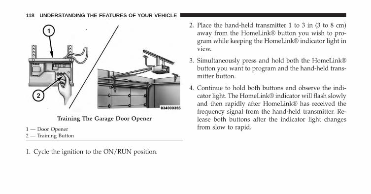
1. Cycle the ignition to the ON/RUN position.
2. Place the hand-held transmitter 1 to 3 in (3 to 8 cm)away from the HomeLink® button you wish to pro-gram while keeping the HomeLink® indicator light inview.
3. Simultaneously press and hold both the HomeLink®button you want to program and the hand-held trans-mitter button.
4. Continue to hold both buttons and observe the indi-cator light. The HomeLink® indicator will flash slowlyand then rapidly after HomeLink® has received thefrequency signal from the hand-held transmitter. Re-lease both buttons after the indicator light changesfrom slow to rapid.
Training The Garage Door Opener
1 — Door Opener2 — Training Button
118 UNDERSTANDING THE FEATURES OF YOUR VEHICLE
5. At the garage door opener motor (in the garage),locate the “LEARN” or “TRAINING” button. This canusually be found where the hanging antenna wire isattached to the garage door opener/device motor.Firmly press and release the “LEARN” or “TRAIN-ING” button. On some garage door openers/devicesthere may be a light that blinks when the garage dooropener/device is in the LEARN/TRAIN mode.
NOTE: You have 30 seconds in which to initiate the nextstep after the LEARN button has been pressed.
6. Return to the vehicle and press the programmedHomeLink® button twice (holding the button for twoseconds each time). If the garage door opener/deviceactivates, programming is complete.
NOTE: If the garage door opener/device does not acti-vate, press the button a third time (for two seconds) tocomplete the training.
To program the remaining two HomeLink® buttons,repeat each step for each remaining button. DO NOTerase the channels.
Reprogramming A Single HomeLink® Button
To reprogram a channel that has been previously trained,follow these steps:
1. Cycle the ignition to the ON/RUN position.
2. Press and hold the desired HomeLink® button untilthe indicator light begins to flash after 20 seconds. Donot release the button.
3. Without releasing the button proceed with “Program-ming A Rolling Code” Step 2 and follow all remainingsteps.
3
UNDERSTANDING THE FEATURES OF YOUR VEHICLE 119
Programming A Non-Rolling Code
For programming Garage Door Openers manufacturedbefore 1995.
1. Cycle the ignition to the ON/RUN position.
2. Place the hand-held transmitter 1 to 3 in (3 to 8 cm)away from the HomeLink® button you wish to pro-gram while keeping the HomeLink® indicator light inview.
3. Simultaneously press and hold both the HomeLink®button you want to program and the hand-held trans-mitter button.
4. Continue to hold both buttons and observe the indi-cator light. HomeLink® indicator will flash slowlyand then rapidly after HomeLink® has received thefrequency signal from the hand-held transmitter. Re-lease both buttons after the indicator light changesfrom slow to rapid.
5. Press and hold the programmed HomeLink® buttonand observe the indicator light.• If the indicator light stays on constantly, program-
ming is complete and the garage door/device shouldactivate when the HomeLink® button is pressed.
• To program the remaining two HomeLink® buttons,repeat each step for each remaining button. DO NOTerase the channels.
Reprogramming A Single HomeLink® Button
To reprogram a channel that has been previously trained,follow these steps:
1. Cycle the ignition to the ON/RUN position.
2. Press and hold the desired HomeLink® button untilthe indicator light begins to flash after 20 seconds. Donot release the button.
120 UNDERSTANDING THE FEATURES OF YOUR VEHICLE
3. Without releasing the button proceed with “Program-ming A Non-Rolling Code” Step 2 and follow allremaining steps.
Canadian/Gate Operator Programming
For programming transmitters in Canada/United Statesthat require the transmitter signals to “time-out” afterseveral seconds of transmission.
Canadian radio frequency laws require transmitter sig-nals to time-out (or quit) after several seconds of trans-mission – which may not be long enough for HomeLink®to pick up the signal during programming. Similar to thisCanadian law, some U.S. gate operators are designed totime-out in the same manner.
It may be helpful to unplug the device during the cyclingprocess to prevent possible overheating of the garagedoor or gate motor.
1. Cycle the ignition to the ON/RUN position.
2. Place the hand-held transmitter 1 to 3 in (3 to 8 cm)away from the HomeLink® button you wish to pro-gram while keeping the HomeLink® indicator light inview.
3. Continue to press and hold the HomeLink® button,while you press and release (“cycle”), your hand-heldtransmitter every two seconds until HomeLink® hassuccessfully accepted the frequency signal. The indi-cator light will flash slowly and then rapidly whenfully trained.
4. Watch for the HomeLink® indicator to change flashrates. When it changes, it is programmed. It may takeup to 30 seconds or longer in rare cases. The garagedoor may open and close while you are programming.
3
UNDERSTANDING THE FEATURES OF YOUR VEHICLE 121
5. Press and hold the programmed HomeLink® buttonand observe the indicator light.• If the indicator light stays on constantly, program-
ming is complete and the garage door/device shouldactivate when the HomeLink® button is pressed.
• To program the two remaining HomeLink® buttons,repeat each step for each remaining button. DO NOTerase the channels.
If you unplugged the garage door opener/device forprogramming, plug it back in at this time.
Reprogramming A Single HomeLink® Button
To reprogram a channel that has been previously trained,follow these steps:
1. Cycle the ignition to the ON/RUN position.
2. Press and hold the desired HomeLink® button untilthe indicator light begins to flash after 20 seconds. Donot release the button.
3. Without releasing the button proceed with“Canadian/Gate Operator Programming” Step 2 andfollow all remaining steps.
Using HomeLink®
To operate, press and release the programmedHomeLink® button. Activation will now occur for theprogrammed device (i.e., garage door opener, gate opera-tor, security system, entry door lock, home/office light-ing, etc.,). The hand-held transmitter of the device mayalso be used at any time.
Security
It is advised to erase all channels before you sell or turnin your vehicle.
To do this, press and hold the two outside buttons for 20seconds until the red indicator flashes. Note that allchannels will be erased. Individual channels cannot beerased.
122 UNDERSTANDING THE FEATURES OF YOUR VEHICLE
The HomeLink® Universal Transceiver is disabled whenthe Vehicle Security Alarm is active.
Troubleshooting Tips
If you are having trouble programming HomeLink®,here are some of the most common solutions:
• Replace the battery in the original hand-held transmit-ter.
• Press the LEARN button on the Garage Door Openerto complete the training for a Rolling Code.
• Did you unplug the device for programming andremember to plug it back in?
If you have any problems, or require assistance, pleasecall toll-free 1–800–355–3515 or, on the Internet atwww.HomeLink.com for information or assistance.
WARNING!
• Your motorized door or gate will open and closewhile you are programming the universal trans-ceiver. Do not program the transceiver if people,pets or other objects are in the path of the door orgate. Only use this transceiver with a garage dooropener that has a “stop and reverse” feature asrequired by Federal safety standards. This includesmost garage door opener models manufacturedafter 1982. Do not use a garage door opener withoutthese safety features. Call toll-free 1–800–355–3515or, on the Internet at www.HomeLink.com forsafety information or assistance.
• Vehicle exhaust contains carbon monoxide, a dan-gerous gas. Do not run your vehicle in the garagewhile programming the transceiver. Exhaust gascan cause serious injury or death.
3
UNDERSTANDING THE FEATURES OF YOUR VEHICLE 123
General Information
This device complies with FCC rules Part 15 and IndustryCanada RSS-210. Operation is subject to the followingtwo conditions:
1. This device may not cause harmful interference.
2. This device must accept any interference that may bereceived including interference that may cause unde-sired operation.
NOTE:
• The transmitter has been tested and it complies with FCCand IC rules. Changes or modifications not expresslyapproved by the party responsible for compliance couldvoid the user’s authority to operate the device.
• The term IC before the certification/registration num-ber only signifies that Industry Canada technical speci-fications were met.
ELECTRICAL POWER OUTLETS
Your vehicle is equipped with two 12 Volt (13 Amp)power outlet that can be used to power cellular phones,small electronics and other low powered electrical acces-sories.
One power outlet is located on the center console to theright of the shifter. Push down on the power outlet toaccess the opening. Push down on it again to close. Thispower outlet is powered when the ignition is in the ONor ACC position.
124 UNDERSTANDING THE FEATURES OF YOUR VEHICLE
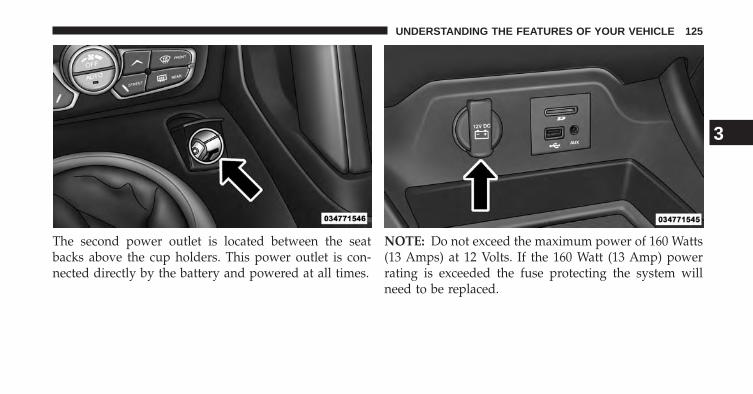
The second power outlet is located between the seatbacks above the cup holders. This power outlet is con-nected directly by the battery and powered at all times.
NOTE: Do not exceed the maximum power of 160 Watts(13 Amps) at 12 Volts. If the 160 Watt (13 Amp) powerrating is exceeded the fuse protecting the system willneed to be replaced.
3
UNDERSTANDING THE FEATURES OF YOUR VEHICLE 125
WARNING!
To avoid serious injury or death:• Only devices designed for use in this type of outlet
should be inserted into any 12 Volt outlet.• Do not touch with wet hands.• Close the lid when not in use and while driving the
vehicle.• If this outlet is mishandled, it may cause an electric
shock and failure.
CAUTION!
• Many accessories that can be plugged in drawpower from the vehicle’s battery, even when not inuse (i.e., cellular phones, etc.). Eventually, ifplugged in long enough, the vehicle’s battery willdischarge sufficiently to degrade battery life and/orprevent the engine from starting.
• Accessories that draw higher power (i.e., coolers,vacuum cleaners, lights, etc.) will degrade the bat-tery even more quickly. Only use these intermit-tently and with greater caution.
• After the use of high power draw accessories, orlong periods of the vehicle not being started (withaccessories still plugged in), the vehicle must bedriven a sufficient length of time to allow thegenerator to recharge the vehicle’s battery.
126 UNDERSTANDING THE FEATURES OF YOUR VEHICLE
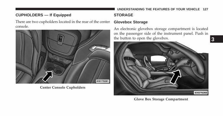
CUPHOLDERS — If Equipped
There are two cupholders located in the rear of the centerconsole.
STORAGE
Glovebox Storage
An electronic glovebox storage compartment is locatedon the passenger side of the instrument panel. Push inthe button to open the glovebox.
Center Console Cupholders
Glove Box Storage Compartment
3
UNDERSTANDING THE FEATURES OF YOUR VEHICLE 127
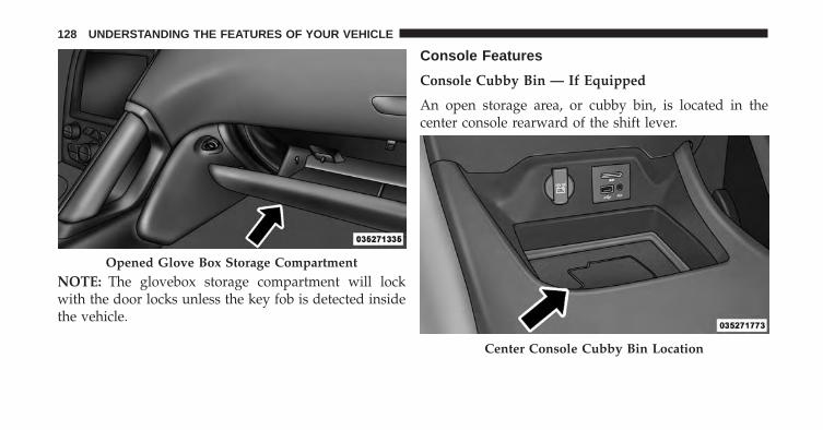
NOTE: The glovebox storage compartment will lockwith the door locks unless the key fob is detected insidethe vehicle.
Console Features
Console Cubby Bin — If Equipped
An open storage area, or cubby bin, is located in thecenter console rearward of the shift lever.
Opened Glove Box Storage Compartment
Center Console Cubby Bin Location
128 UNDERSTANDING THE FEATURES OF YOUR VEHICLE
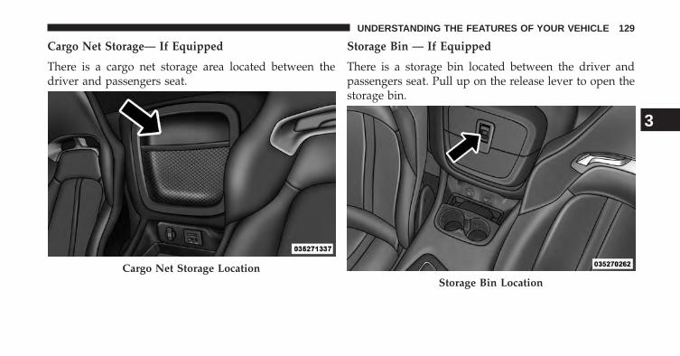
Cargo Net Storage— If Equipped
There is a cargo net storage area located between thedriver and passengers seat.
Storage Bin — If Equipped
There is a storage bin located between the driver andpassengers seat. Pull up on the release lever to open thestorage bin.
Cargo Net Storage LocationStorage Bin Location
3
UNDERSTANDING THE FEATURES OF YOUR VEHICLE 129
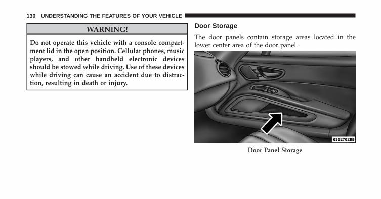
WARNING!
Do not operate this vehicle with a console compart-ment lid in the open position. Cellular phones, musicplayers, and other handheld electronic devicesshould be stowed while driving. Use of these deviceswhile driving can cause an accident due to distrac-tion, resulting in death or injury.
Door Storage
The door panels contain storage areas located in thelower center area of the door panel.
Door Panel Storage
130 UNDERSTANDING THE FEATURES OF YOUR VEHICLE
REAR WINDOW FEATURES
Rear Window Defroster
The rear window defroster button is located onthe climate control panel. Press this button to turn
on the rear window defroster. An indicator in the buttonwill illuminate when the rear window defroster is on. Therear window defroster automatically turns off after ap-proximately 10 minutes. For an additional five minutes ofoperation, press the button a second time.
NOTE: To prevent excessive battery drain, use the rearwindow defroster only when the engine is operating.
CAUTION!
Failure to follow these cautions can cause damage tothe heating elements:• Use care when washing the inside of the rear
window. Do not use abrasive window cleaners onthe interior surface of the window. Use a soft clothand a mild washing solution, wiping parallel to theheating elements. Labels can be peeled off aftersoaking with warm water.
• Do not use scrapers, sharp instruments, or abrasivewindow cleaners on the interior surface of thewindow.
• Keep all objects a safe distance from the window.
3
UNDERSTANDING THE FEATURES OF YOUR VEHICLE 131

UNDERSTANDING YOUR INSTRUMENT PANEL
CONTENTS� INSTRUMENT PANEL FEATURES . . . . . . . . . .135
� INSTRUMENT CLUSTER . . . . . . . . . . . . . . . . .136
� INSTRUMENT CLUSTER DESCRIPTIONS . . . . .137
� ELECTRONIC VEHICLE INFORMATIONCENTER (EVIC) . . . . . . . . . . . . . . . . . . . . . . . .148
▫ Electronic Vehicle Information Center (EVIC)Displays . . . . . . . . . . . . . . . . . . . . . . . . . . . .150
▫ Electronic Vehicle Information Center (EVIC)Messages . . . . . . . . . . . . . . . . . . . . . . . . . . .152
▫ EVIC Amber Telltales . . . . . . . . . . . . . . . . . . .154
▫ EVIC Red Telltales . . . . . . . . . . . . . . . . . . . . .154
▫ EVIC Green Telltales . . . . . . . . . . . . . . . . . . .156
▫ EVIC Selectable Menu Items . . . . . . . . . . . . . .156
▫ Screen Setup Driver Selectable Items . . . . . . . .162
� Uconnect® SETTINGS. . . . . . . . . . . . . . . . . . . .163
▫ Hard-Keys . . . . . . . . . . . . . . . . . . . . . . . . . .164
▫ Soft-Keys . . . . . . . . . . . . . . . . . . . . . . . . . . .164
▫ Customer Programmable Features —Uconnect® System Settings. . . . . . . . . . . . . . .164
� Uconnect® RADIOS — IF EQUIPPED . . . . . . . .176
� iPod®/USB/MP3 CONTROL — IF EQUIPPED . .176
4
� STEERING WHEEL AUDIO CONTROLS . . . . . .176
▫ Radio Operation . . . . . . . . . . . . . . . . . . . . . .177
� RADIO ANTENNA . . . . . . . . . . . . . . . . . . . . .177
� RADIO OPERATION AND MOBILE PHONES . .177
� CLIMATE CONTROLS . . . . . . . . . . . . . . . . . . .177
▫ Automatic Temperature Control (ATC). . . . . . .178
▫ Summer Operation . . . . . . . . . . . . . . . . . . . .184
▫ Winter Operation. . . . . . . . . . . . . . . . . . . . . .184
▫ Vacation/Storage . . . . . . . . . . . . . . . . . . . . .184
▫ Window Fogging and Frosting . . . . . . . . . . . .184
▫ Outside Air Intake . . . . . . . . . . . . . . . . . . . . .185
▫ Control Setting Suggestions for VariousWeather Conditions . . . . . . . . . . . . . . . . . . .185
134 UNDERSTANDING YOUR INSTRUMENT PANEL
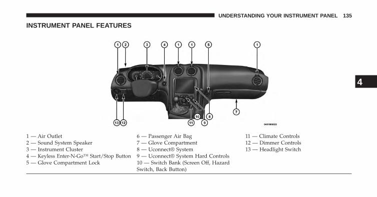
INSTRUMENT PANEL FEATURES
1 — Air Outlet 6 — Passenger Air Bag 11 — Climate Controls2 — Sound System Speaker 7 — Glove Compartment 12 — Dimmer Controls3 — Instrument Cluster 8 — Uconnect® System 13 — Headlight Switch4 — Keyless Enter-N-Go™ Start/Stop Button 9 — Uconnect® System Hard Controls5 — Glove Compartment Lock 10 — Switch Bank (Screen Off, Hazard
Switch, Back Button)
4
UNDERSTANDING YOUR INSTRUMENT PANEL 135
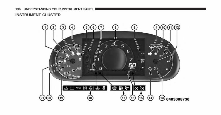
INSTRUMENT CLUSTER
136 UNDERSTANDING YOUR INSTRUMENT PANEL
INSTRUMENT CLUSTER DESCRIPTIONS
1. Speedometer
Indicates vehicle speed.
2. Air Bag Warning Light
This light will turn on for four to eight secondsas a bulb check when the ignition is first cycledto ON/RUN. If the light is either not on duringstarting, stays on, or turns on while driving,
have the system inspected at an authorized dealer assoon as possible. Refer to “Occupant Restraints” in“Things To Know Before Starting Your Vehicle” forfurther information.
3. Seat Belt Reminder Light
When the ignition is first cycled to ON/RUN, thislight will turn on for four to eight seconds as abulb check. During the bulb check, if the driver’s
seat belt is unbuckled, a chime will sound. After the bulbcheck or when driving, if the driver’s seat belt remainsunbuckled, the Seat Belt Reminder Light will illuminateand the chime will sound. Refer to “Occupant Restraints”in “Things To Know Before Starting Your Vehicle” forfurther information.
4. Turn Signal Indicators
The arrow will flash with the exterior turn signalwhen the turn signal lever is operated.
If the vehicle electronics sense that the vehicle is drivenmore than 1 mile (1.6 km) with either turn signal on, acontinuous chime will sound to alert you to turn thesignals off. If either indicator flashes at a rapid rate, checkfor a defective outside light bulb.
4
UNDERSTANDING YOUR INSTRUMENT PANEL 137
Both turn signal arrows will flash in unison with the frontand rear turn signals when the HAZARD WARNINGbutton is operated.
NOTE: Leaving the hazard flashers on for extendedperiods will wear down the battery.
5. Electronic Stability Control (ESC) Activation/Malfunction Indicator Light — If Equipped
The “ESC Activation/Malfunction IndicatorLight” in the instrument cluster will come onwhen the ignition is cycled to the ON/RUNposition. It should go out with the engine run-
ning. If the “ESC Activation/Malfunction Indicator Light”comes on continuously with the engine running, a mal-function has been detected in the ESC system. If this lightremains on after several ignition cycles, and the vehicle hasbeen driven several miles (kilometers) at speeds greaterthan 30 mph (48 km/h), see your authorized dealer as soonas possible to have the problem diagnosed and corrected.
NOTE:
• The “ESC Off Indicator Light” and the “ESCActivation/Malfunction Indicator Light” come on mo-mentarily each time the ignition is cycled to ON/RUN.
• Each time the ignition is cycled to ON/RUN, the ESCsystem will be ON, even if it was turned off previously.
• The ESC system will make buzzing or clicking soundswhen it is active. This is normal; the sounds will stopwhen ESC becomes inactive following the maneuverthat caused the ESC activation.
6. EVIC Menu Set (Selectable ICONS)
The EVIC displays are located In the center portion of thecluster and consists of eight section:
• Speedometer (Digital or Analog) (km/h or mph)
138 UNDERSTANDING YOUR INSTRUMENT PANEL
• Main Screen — The inner ring of the display willilluminate in gray under normal conditions, yellow fornon critical warning, red for critical warnings andwhite for on demand information.
• Selectable Information (Compass, Temp, Range, toEmpty, Trip A, Trip B, Average MPG)
• Menu Titles / Odometer
• Menu Set (Selectable Icons)
• Shift Lever Status (PRNDL)
• Reconfigurable Telltales
• Audio / Phone Information
• Sub-menu Current Position — Whenever there aresub-menus available, the position within the sub-menus is here
Refer to Electronic Vehicle Information Center (EVIC) forfurther information.
7. Brake Warning Light
This light monitors various brake functions,including brake fluid level and parking brakeapplication. If the brake light turns on it mayindicate that the parking brake is applied, that
the brake fluid level is low, or that there is a problem withthe anti-lock brake system reservoir.
If the light remains on when the parking brake has beendisengaged, and the fluid level is at the full mark on themaster cylinder reservoir, it indicates a possible brakehydraulic system malfunction or that a problem with theBrake Booster has been detected by the Anti-Lock BrakeSystem (ABS) / Electronic Stability Control (ESC) system.In this case, the light will remain on until the conditionhas been corrected. If the problem is related to the brakebooster, the ABS pump will run when applying the brakeand a brake pedal pulsation may be felt during each stop.
4
UNDERSTANDING YOUR INSTRUMENT PANEL 139
The dual brake system provides a reserve braking capac-ity in the event of a failure to a portion of the hydraulicsystem. A leak in either half of the dual brake system isindicated by the Brake Warning Light, which will turn onwhen the brake fluid level in the master cylinder hasdropped below a specified level.
The light will remain on until the cause is corrected.
WARNING!
Driving a vehicle with the red brake light on isdangerous. Part of the brake system may have failed.It will take longer to stop the vehicle. You could havea collision. Have the vehicle checked immediately.
Vehicles equipped with the Anti-Lock Brake System(ABS), are also equipped with Electronic Brake ForceDistribution (EBD). In the event of an EBD failure, theBrake Warning Light will turn on along with the ABSLight. Immediate repair to the ABS system is required.
Operation of the Brake Warning Light can be checked bycycling the ignition from the OFF position to the ON/RUN position. The light should illuminate for approxi-mately two seconds. The light should then turn off unlessthe parking brake is applied or a brake fault is detected.If the light does not illuminate, have the light inspectedby an authorized dealer.
The light also will turn on when the parking brake isapplied with the ignition in the ON/RUN position.
NOTE: This light shows only that the parking brake isapplied. It does not show the degree of brake application.
8. Tachometer
This gauge measures engine revolutions-per-minute(RPM x 1000)
140 UNDERSTANDING YOUR INSTRUMENT PANEL
9. Oil Pressure Warning Light
This light indicates low engine oil pressure. Thelight should turn on momentarily when the engine isstarted. If the light turns on while driving, stop thevehicle and shut off the engine as soon as possible. Achime will sound when this light turns on.
Do not operate the vehicle until the cause is corrected.This light does not indicate how much oil is in the engine.The engine oil level must be checked under the hood.
The oil level should be maintained in the �SAFE� zone atall times. Oil level below the �SAFE� zone can cause theoil pressure warning lamp to illuminate under someconditions and can cause engine damage.
10. Vehicle Security Light — If Equipped
This light will flash at a fast rate for approxi-mately 15 seconds, when the vehicle securityalarm is arming, and then will flash slowlyuntil the vehicle is disarmed.
11. High Beam Indicator
This indicator shows that the high beam head-lights are on. Push the multifunction lever for-
ward to switch the headlights to high beam, and pulltoward yourself (normal position) to return to low beam.
12. Fuel Gauge/Fuel Door Reminder
The pointer shows the level of fuel in the fuel tank whenthe ignition is in the ON/RUN position. The arrow in thissymbol is a reminder that the Fuel Filler Door is locatedon the left side of the vehicle.
4
UNDERSTANDING YOUR INSTRUMENT PANEL 141
13. Tire Pressure Monitoring Telltale Light — If Equipped
Each tire, should be checked monthly when coldand inflated to the inflation pressure recom-mended by the vehicle manufacturer on thevehicle placard or tire inflation pressure label. (If
your vehicle has tires of a different size than the sizeindicated on the vehicle placard or tire inflation pressurelabel, you should determine the proper tire inflation pres-sure for those tires.)
As an added safety feature, your vehicle has beenequipped with a Tire Pressure Monitoring System (TPMS)that illuminates a low tire pressure telltale when one ormore of your tires is significantly under-inflated. Accord-ingly, when the low tire pressure telltale illuminates, youshould stop and check your tires as soon as possible, andinflate them to the proper pressure. Driving on a signifi-cantly under-inflated tire causes the tire to overheat andcan lead to tire failure. Under-inflation also reduces fuel
efficiency and tire tread life, and may affect the vehicle’shandling and stopping ability.
Please note that the TPMS is not a substitute for propertire maintenance, and it is the driver’s responsibility tomaintain correct tire pressure, even if under-inflation hasnot reached the level to trigger illumination of the TPMSlow tire pressure telltale.
Your vehicle has also been equipped with a TPMS malfunc-tion indicator to indicate when the system is not operatingproperly. The TPMS malfunction indicator is combinedwith the low tire pressure telltale. When the system detectsa malfunction, the telltale will flash for approximately oneminute and then remain continuously illuminated. Thissequence will continue upon subsequent vehicle start-upsas long as the malfunction exists. When the malfunctionindicator is illuminated, the system may not be able todetect or signal low tire pressure as intended. TPMSmalfunctions may occur for a variety of reasons, includingthe installation of replacement or alternate tires or wheels
142 UNDERSTANDING YOUR INSTRUMENT PANEL
on the vehicle that prevent the TPMS from functioningproperly. Always check the TPMS malfunction telltale afterreplacing one or more tires or wheels on your vehicle, toensure that the replacement or alternate tires and wheelsallow the TPMS to continue to function properly.
CAUTION!
The TPMS has been optimized for the originalequipment tires and wheels. TPMS pressures andwarning have been established for the tire sizeequipped on your vehicle. Undesirable system opera-tion or sensor damage may result when using re-placement equipment that is not of the same size,type, and/or style. Aftermarket wheels can causesensor damage. Do not use tire sealant from a can orbalance beads if your vehicle is equipped with aTPMS, as damage to the sensors may result.
14. Malfunction Indicator Light (MIL)
The Malfunction Indicator Light (MIL) is part ofan onboard diagnostic system, called OBD, thatmonitors engine control systems. The light will
illuminate when the ignition is in the ON/RUN position,before engine start. If the bulb does not come on whencycling the ignition from OFF to ON/RUN, have thecondition checked promptly.
Certain conditions, such as poor fuel quality, etc., mayilluminate the MIL after engine start. The vehicle shouldbe serviced if the light stays on through several of yourtypical driving cycles. In most situations, the vehicle willdrive normally and will not require towing.
4
UNDERSTANDING YOUR INSTRUMENT PANEL 143
CAUTION!
Prolonged driving with the Malfunction IndicatorLight (MIL) on could cause damage to the enginecontrol system. It also could affect fuel economy anddriveability. If the MIL is flashing, severe catalyticconverter damage and power loss will soon occur.Immediate service is required.
WARNING!
A malfunctioning catalytic converter, as referencedabove, can reach higher temperatures than in normaloperating conditions. This can cause a fire if youdrive slowly or park over flammable substances suchas dry plants, wood, cardboard, etc. This could resultin death or serious injury to the driver, occupants orothers.
15. Electronic Speed Control Indicator Lights• Electronic Speed Control ON Indicator
This light will turn on when the electronicspeed control is ON. For further information,refer to “Electronic Speed Control” in “Under-standing The Features Of Your Vehicle.”
• Electronic Speed Control SET IndicatorThis light will turn on when the electronicspeed control is SET. For further information,refer to “Electronic Speed Control” in “Under-standing The Features Of Your Vehicle.”
16. Cruise Speed Set Value
Speed value shown when set.
144 UNDERSTANDING YOUR INSTRUMENT PANEL
17. EVIC Amber Telltale Lights
When the appropriate conditions exist, the followingEVIC Amber Telltale Lights will display:• Windshield Washer Fluid Low Indicator — If Equipped
This light will turn on to indicate the wind-shield washer fluid is low
• Low Fuel LightWhen the fuel level reaches approximately 3.0 gal(11.0 L) this light will turn on, and remain on untilfuel is added.
18. EVIC Red Telltale Lights
When the appropriate conditions exist, the followingEVIC Red Telltale Lights will display:• Engine Temperature
This telltale warns of an overheated engine con-dition. As temperatures rise and the gauge ap-proaches H, or 260°F, this telltale will illuminate
and a single chime will sound after reaching a setthreshold. Further overheating will cause the tempera-ture gauge to pass H, or 260°F, a continuous chime willoccur until the engine is allowed to cool.If the telltale turns on while driving, safely pull over andstop the vehicle. If the A/C system is on, turn it off. Also,shift the transmission into NEUTRAL and idle the ve-hicle. If the temperature reading does not return tonormal, turn the engine off immediately and call forservice. Refer to “If Your Engine Overheats” in “What ToDo In Emergencies” for more information.
4
UNDERSTANDING YOUR INSTRUMENT PANEL 145
• Charging SystemThis telltale shows the status of the electricalcharging system. If the telltale stays on or comes
on while driving, turn off some of the vehicle’s non-essential electrical devices or increase engine speed (if atidle). If the charging system telltale remains on, it meansthat the vehicle is experiencing a problem with thecharging system. Obtain SERVICE IMMEDIATELY. Seean authorized dealer.If jump starting is required, refer to “Jump StartingProcedures” in “What To Do In Emergencies”.• Oil Pressure Warning
This telltale indicates low engine oil pressure. Ifthe light turns on while driving, stop the vehicle
and shut off the engine as soon as possible. A chime willsound for four minutes when this light turns on.Do not operate the vehicle until the cause is corrected.This light does not show how much oil is in the engine.The engine oil level must be checked under the hood.
• Electronic Throttle Control (ETC)This telltale informs you of a problem with theElectronic Throttle Control (ETC) system. If thetelltale comes on while driving, have the sys-tem checked by an authorized dealer.
If a problem is detected, the telltale will come on whilethe engine is running. Cycle the ignition when the vehiclehas completely stopped and the shift lever is placed inthe NEUTRAL position and the parking brake applied.The telltale should turn off.If the telltale remains lit with the engine running, yourvehicle will usually be drivable. However, see an autho-rized dealer for service as soon as possible. If the telltaleis flashing when the engine is running, immediate serviceis required. You may experience reduced performance, anelevated/rough idle or engine stall and your vehicle mayrequire towing.
146 UNDERSTANDING YOUR INSTRUMENT PANEL
• Oil Temperature Warning LightThis telltale indicates high engine oil tempera-ture. If the light turns on while driving, stopthe vehicle and shut off the engine as soon aspossible. A chime will sound for four minutes
when this light turns on.• Door Ajar
This telltale turns on when one or more doorsare ajar. The telltale will show which doors areajar.
19. Anti-Lock Brake (ABS) Light
This light monitors the Anti-Lock Brake System(ABS). The light will turn on when the ignitionis cycled to the ON/RUN position and maystay on for as long as four seconds.
If the ABS light remains on or turns on while driving, itindicates that the Anti-Lock portion of the brake systemis not functioning and that service is required. However,
the conventional brake system will continue to operatenormally if the BRAKE warning light is not on.
If the ABS light is on, the brake system should be servicedas soon as possible to restore the benefits of Anti-Lockbrakes. If the ABS light does not turn on when theignition is cycled to the ON/RUN position, have the lightinspected by an authorized dealer.
20. Park/Headlight ON Indicator — If Equipped
This indicator will illuminate when the parklights or headlights are turned on.
21. Electronic Stability Control (ESC) OFF IndicatorLight — If Equipped
This light indicates the Electronic Stability Con-trol (ESC) is off.
4
UNDERSTANDING YOUR INSTRUMENT PANEL 147
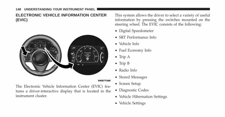
ELECTRONIC VEHICLE INFORMATION CENTER(EVIC)
The Electronic Vehicle Information Center (EVIC) fea-tures a driver-interactive display that is located in theinstrument cluster.
This system allows the driver to select a variety of usefulinformation by pressing the switches mounted on thesteering wheel. The EVIC consists of the following:
• Digital Speedometer
• SRT Performance Info
• Vehicle Info
• Fuel Economy Info
• Trip A
• Trip B
• Radio Info
• Stored Messages
• Screen Setup
• Diagnostic Codes
• Vehicle Hibernation Settings
• Vehicle Settings
148 UNDERSTANDING YOUR INSTRUMENT PANEL
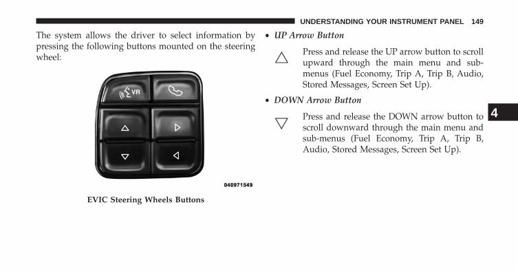
The system allows the driver to select information bypressing the following buttons mounted on the steeringwheel:
• UP Arrow Button
Press and release the UP arrow button to scrollupward through the main menu and sub-menus (Fuel Economy, Trip A, Trip B, Audio,Stored Messages, Screen Set Up).
• DOWN Arrow Button
Press and release the DOWN arrow button toscroll downward through the main menu andsub-menus (Fuel Economy, Trip A, Trip B,Audio, Stored Messages, Screen Set Up).
EVIC Steering Wheels Buttons
4
UNDERSTANDING YOUR INSTRUMENT PANEL 149
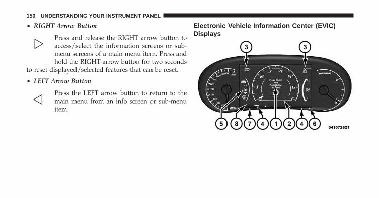
• RIGHT Arrow Button
Press and release the RIGHT arrow button toaccess/select the information screens or sub-menu screens of a main menu item. Press andhold the RIGHT arrow button for two seconds
to reset displayed/selected features that can be reset.
• LEFT Arrow Button
Press the LEFT arrow button to return to themain menu from an info screen or sub-menuitem.
Electronic Vehicle Information Center (EVIC)Displays
150 UNDERSTANDING YOUR INSTRUMENT PANEL
The EVIC displays are located in the center portion of thecluster and consists of the following sections:
1. Main Screen — The inner ring of the display willilluminate in grey under normal conditions, yellow fornon critical warnings, red for critical warnings andwhite for on demand information.
2. Audio / Phone Information and Sub-menu Informa-tion — Whenever there are sub-menus available, theposition within the sub-menus is shown here.
3. Reconfigurable Telltales/Information
4. Telltales/Indicators
5. Selectable Information (Vehicle Info, SRT, Fuel Economy,Stored Messages, Audio, Trip A, Trip B, Average MPG)
6. Suspension Status — The suspension status icon willilluminate in this area. Refer to “Starting And Operat-ing” for further information.
7. ESC Status — The ESC status icon will illuminate inthis area. Refer to “Starting And Operating” for fur-ther information.
8. Launch Control status when launch control mode isentered. Refer to “Starting And Operating” for furtherinformation.
The main display area will normally display the mainmenu or the screens of a selected feature of the mainmenu. The main display area also displays “pop up”messages that consist of approximately 60 possible warn-ing or information messages. These pop up messages fallinto several categories:
• Five Second Stored Messages
When the appropriate conditions occur, this type ofmessage takes control of the main display area for fiveseconds and then returns to the previous screen. Most ofthe messages of this type are then stored (as long as thecondition that activated it remains active) and can be
4
UNDERSTANDING YOUR INSTRUMENT PANEL 151
reviewed from the “Messages” main menu item. As longas there is a stored message, an “i” will be displayed inthe EVIC’s compass/outside temp line. Examples of thismessage type are “Right Front Turn Signal Lamp Out”and “Low Tire Pressure”.
• Unstored Messages
This message type is displayed indefinitely or until thecondition that activated the message is cleared. Examplesof this message type are “Turn Signal On” (if a turn signalis left on) and “Lights On” (if driver leaves the vehicle).
• Five Second Unstored Messages
When the appropriate conditions occur, this type ofmessage takes control of the main display area for fiveseconds and then returns to the previous screen. Anexample of this message type is “Automatic High BeamsOn”.
Electronic Vehicle Information Center (EVIC)Messages
• Front Seatbelts Unbuckled
• Driver Seatbelt Unbuckled
• Passenger Seatbelt Unbuckled
• Key Fob Battery Low
• Service Airbag System
• ESC Status (ESC OFF, ESC ON, ESC SPORT, ESCTRACK, RAIN MODE) — Refer to “Starting AndOperating” for further information.
• Oil Pressure Low
• Fuel Low
• Service Antilock Brake System
• Service Electronic Throttle Control
152 UNDERSTANDING YOUR INSTRUMENT PANEL
• Cruise Off
• Cruise Ready
• Cruise Set To XXX MPH
• Tire Pressure Screen With Low Tire Pressure Warnings
• Service Tire Pressure System
• Parking Brake Engaged
• Brake Fluid Low
• Service Electronic Braking System
• Engine Temperature Hot
• Battery Voltage Low
• Service Electronic Throttle Control
• Lights On
• Right Turn Signal Light Out
• Left Turn Signal Light Out
• Turn Signal On
• Service Airbag System
• Service Airbag Warning Light
• Driver Seatbelt Unbuckled
• Passenger Seatbelt Unbuckled
• Front Seatbelts Unbuckled
• Door Open
• Doors Open
• Engage Park Brake to Prevent Rolling
4
UNDERSTANDING YOUR INSTRUMENT PANEL 153
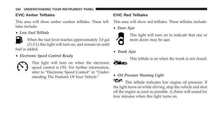
EVIC Amber Telltales
This area will show amber caution telltales. These tell-tales include:
• Low Fuel Telltale
When the fuel level reaches approximately 3.0 gal(11.0 L) this light will turn on, and remain on until
fuel is added.
• Electronic Speed Control Ready
This light will turn on when the electronicspeed control is ON. For further information,refer to “Electronic Speed Control” in “Under-standing The Features Of Your Vehicle.”
EVIC Red Telltales
This area will show red telltales. These telltales include:
• Door Ajar
This light will turn on to indicate that one ormore doors may be ajar.
• Trunk Ajar
This telltale is on when the trunk is not closed.
• Oil Pressure Warning Light
This telltale indicates low engine oil pressure. Ifthe light turns on while driving, stop the vehicle and shutoff the engine as soon as possible. A chime will sound forfour minutes when this light turns on.
154 UNDERSTANDING YOUR INSTRUMENT PANEL
Do not operate the vehicle until the cause is corrected.This light does not show how much oil is in the engine.The engine oil level must be checked under the hood.
The oil level should be maintained in the �SAFE� zone atall times. Oil level below the �SAFE� zone can cause theoil pressure warning lamp to illuminate under someconditions and can cause engine damage.
• Charging System Light
This light shows the status of the electrical chargingsystem. If the light stays on or comes on while
driving, turn off some of the vehicle’s non-essential elec-trical devices or increase engine speed (if at idle). If thecharging system light remains on, it means that the vehicleis experiencing a problem with the charging system. ObtainSERVICE IMMEDIATELY. See an authorized dealer.
If jump starting is required, refer to “Jump StartingProcedures” in “What To Do In Emergencies”.
• Electronic Throttle Control (ETC) Light
This light informs you of a problem with theElectronic Throttle Control (ETC) system. Thelight will come on when the ignition is firstcycled ON and remain on briefly as a bulb
check. If the light does not come on during starting, havethe system checked by an authorized dealer.
If a problem is detected, the light will come on while theengine is running. Cycle the ignition when the vehiclehas completely stopped and the shift lever is in Neutral,with the Parking Brake applied. The light should turn off.
If the light remains lit with the engine running, yourvehicle will usually be drivable. However, see an autho-rized dealer for service as soon as possible. If the light isflashing when the engine is running, immediate service isrequired. You may experience reduced performance, anelevated/rough idle or engine stall and your vehicle mayrequire towing.
4
UNDERSTANDING YOUR INSTRUMENT PANEL 155
• Engine Temperature Warning Light
This light warns of an overheated engine condi-tion. As temperatures rise and the gauge ap-
proaches H, this indicator will illuminate and a singlechime will sound after reaching a set threshold. Furtheroverheating will cause the temperature gauge to pass H,the indicator will continuously flash and a continuouschime will occur until the engine is allowed to cool.
If the light turns on while driving, safely pull over andstop the vehicle. If the A/C system is on, turn it off. Also,shift the transmission into NEUTRAL and idle the ve-hicle. If the temperature reading does not return tonormal, turn the engine off immediately and call forservice. Refer to “If Your Engine Overheats” in “What ToDo In Emergencies” for more information.
EVIC Green Telltales
• Electronic Speed Control SET
This telltale will illuminate green when the elec-tronic speed control is SET. For further informa-tion, refer to “Electronic Speed Control” in “Un-derstanding The Features Of Your Vehicle.”
EVIC Selectable Menu Items
Press and release the UP or DOWN arrow buttons until thedesired Selectable Menu icon is highlighted in the EVIC.
Tachometer
Press and release the UP or DOWN arrowbutton until the Tachometer icon is highlightedin the EVIC. Press and release the RIGHTarrow button to change the display between
full tachometer or with digital speedometer.
156 UNDERSTANDING YOUR INSTRUMENT PANEL
MPH — km/h
Press and release the UP or DOWN arrow button untilthe MPH-km/h icon is highlighted in the EVIC. Pressand release the RIGHT arrow button to change thedisplay between MPH or km/h
Vehicle Info (Customer Information Features)
Press and release the UP or DOWN arrowbutton until the Vehicle Info icon is highlightedin the EVIC. Press and release the RIGHTarrow button and Coolant Temp will be dis-
played. Press the UP or DOWN arrow button to scrollthrough the following information sub-menus:
Tire Pressure
Press and release the UP or DOWN arrow button until“Tire Pressure” is highlighted in the EVIC. Press andrelease the RIGHT arrow button and one of the followingwill be displayed:
• If tire pressure is OK for all tires a vehicle ICON isdisplayed with tire pressure values in each corner ofthe ICON.
• If one or more tires have low pressure, The tirepressure values in each corner of the ICON with thepressure value of the low tire displayed in a differentcolor than the other tire pressure value.
• If the Tire Pressure system requires service, “ServiceTire Pressure System” is displayed.
Tire PSI is an information only function and cannot bereset. Press and release the LEFT arrow button to returnto the main menu.
4
UNDERSTANDING YOUR INSTRUMENT PANEL 157
Refer to “Tire Pressure Monitoring System (TPMS)”under “Starting and Operating” for further information.
Coolant Temperature
Press and release the UP or DOWN arrow button until“Coolant Temperature” is highlighted in the EVIC. Pressand release the RIGHT arrow button and the coolanttemperature will be displayed.
Oil Temperature
Press and release the UP or DOWN arrow button until“Oil Temperature” is highlighted in the EVIC. Press andrelease the RIGHT arrow button and the oil temperaturewill be displayed.
Battery Voltage
Press and release the UP or DOWN arrow button until“Battery Voltage” is highlighted in the EVIC. Press andrelease the RIGHT arrow button and the battery voltagewill be displayed.
Intake Air Temp.
Press and release the UP or DOWN arrow button until“Intake Air Temp.” is highlighted in the EVIC. Press andrelease the RIGHT arrow button and the intake airtemperature will be displayed.
Current Torque
Press and release the UP or DOWN arrow button until“Current Torque” is highlighted in the EVIC. Press andrelease the RIGHT arrow button and the current torquewill be displayed.
Current Power
Press and release the UP or DOWN arrow button until“Current Power” is highlighted in the EVIC. Press andrelease the RIGHT arrow button and the current powerwill be displayed.
158 UNDERSTANDING YOUR INSTRUMENT PANEL
SRT Performance Info
WARNING!
Measurement of vehicle statistics with the Perfor-mance Features is intended for off-highway or off-road use only and should not be done on any publicroadways. It is recommended that these features beused in a controlled environment and within thelimits of the law. The capabilities of the vehicle asmeasured by the performance pages must never beexploited in a reckless or dangerous manner, whichcan jeopardize the user’s safety or the safety ofothers. Only a safe, attentive, and skillful driver canprevent accidents.
Press and release the UP or DOWN arrow button untilthe SRT icon is highlighted in the EVIC. Press and releasethe RIGHT arrow button and 0–60 MPH Duration will bedisplayed. Press the UP or DOWN arrow button to scrollthrough the following information sub-menus:
Braking Distance
Press and release the UP or DOWN arrow button untilthe last Braking Distance information is displayed.
1/8 Mile Top Speed & Duration
Press and release the UP or DOWN arrow button untilthe last 1/8 Mile Top Speed & Duration information isdisplayed.
Current G-Forces
Press and release the UP or DOWN arrow button untilthe Current G-Forces are displayed.
4
UNDERSTANDING YOUR INSTRUMENT PANEL 159
Peak G-Forces
Press and release the UP or DOWN arrow button untilthe Peak G-Forces are displayed.
0–60 MPH
Press and release the UP or DOWN arrow button untilthe last 0–60 MPH information is displayed.
Fuel Economy
Press and release the UP or DOWN arrowbutton until the Fuel Economy icon is high-lighted. Press the RIGHT arrow button and thenext screen will display the following:
• Average Fuel Economy/Miles Per Gallon (MPG Bargraph)
• Range To Empty (RTE)
• Current Miles Per Gallon (MPG)
Trip A
Press and release the UP or DOWN arrowbutton until the Trip A icon is highlighted inthe EVIC. The Trip A information will displaythe following:
• Distance
• Average Fuel Economy
• Average Speed
• Elapsed Time
Hold the SELECT/RIGHT arrow button to reset all theinformation.
160 UNDERSTANDING YOUR INSTRUMENT PANEL
Trip B
Press and release Up & Down arrow button untilthe Trip B icon is highlighted in the EVIC. TheTrip B information will display the following:
• Distance
• Average Fuel Economy
• Average Speed
• Elapsed Time
Hold the SELECT/RIGHT arrow button to reset all theinformation.
Audio
Press and release the UP or DOWN arrow buttonuntil the Audio display icon is highlighted in theEVIC. Press and release the SELECT/RIGHTarrow button to display the active source.
Stored Messages
Press and release the UP arrow button until theMessages display icon is highlighted in theEVIC. This feature shows the number of storedwarning messages. Pressing the RIGHT arrow
button will allow you to see what the stored messages are.
4
UNDERSTANDING YOUR INSTRUMENT PANEL 161
Diagnostic Codes
Press and release the UP or DOWN arrowbutton until the Diagnostic Code icon is high-lighted in the EVIC. Press and release theRIGHT arrow button to display any present
diagnostic trouble codes along with a brief definition.
Vehicle Hibernation
Press and release the UP or DOWN arrowbutton until the Hibernation icon is highlightedin the EVIC. Press and release the RIGHTarrow button to activate the Vehicle Hiberna-
tion Mode, which minimizes vehicle battery drain whilethe vehicle is being stored.
Screen Setup Driver Selectable Items
Upper Left
• None
• Compass
• Outside Temp (default setting)
• Time
• Range To Empty (RTE)
• Average MPG
• Current MPG
• Trip A
• Trip B
• Coolant Temp.
• Oil Temp.
• Battery Voltage
162 UNDERSTANDING YOUR INSTRUMENT PANEL
Upper Right
• None
• Compass (default setting)
• Outside Temp
• Time
• Range To Empty (RTE)
• Average MPG
• Current MPG
• Trip A
• Trip B
• Coolant Temp.
• Oil Temp.
• Battery Voltage
Restore To Defaults (Restores All Settings To DefaultSettings)
• Cancel
• Okay
Uconnect® SETTINGS
The Uconnect® system uses a combination of soft andhard keys located on the center of the instrument panelthat allows you to access and change the customerprogrammable features.
4
UNDERSTANDING YOUR INSTRUMENT PANEL 163
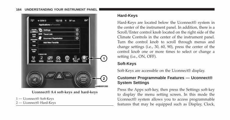
Hard-Keys
Hard-Keys are located below the Uconnect® system inthe center of the instrument panel. In addition, there is aScroll/Enter control knob located on the right side of theClimate Controls in the center of the instrument panel.Turn the control knob to scroll through menus andchange settings (i.e., 30, 60, 90), press the center of thecontrol knob one or more times to select or change asetting (i.e., ON, OFF).
Soft-Keys
Soft-Keys are accessible on the Uconnect® display.
Customer Programmable Features — Uconnect®System Settings
Press the Apps soft-key, then press the Settings soft-keyto display the menu setting screen. In this mode theUconnect® system allows you to access programmablefeatures that may be equipped such as Display, Clock,
Uconnect® 8.4 soft-keys and hard-keys
1 — Uconnect® Soft-Keys2 — Uconnect® Hard-Keys
164 UNDERSTANDING YOUR INSTRUMENT PANEL
Safety/Assistance, Lights, Doors & Locks, Auto-OnComfort, Engine Off Operation, Compass Settings, Au-dio, Phone/Bluetooth and SiriusXM Setup.
NOTE: Only one touchscreen area may be selected at atime.
When making a selection, press the soft-key to enter thedesired mode. Once in the desired mode press andrelease the preferred setting until a check-mark appearsnext to the setting, showing that setting has been se-lected.
Once the setting is complete press the Back Arrowsoft-key to return to the previous menu or press the Xsoft-key to close out of the settings screen. Pressing theUp or Down Arrow soft-keys on the right side of thescreen will allow you to toggle up or down through theavailable settings.
Display
After pressing the Display soft-key the following settingswill be available.
• Display Mode
When in this display you may select one of the autodisplay settings. To change Mode status, touch andrelease the Day, Night or Auto soft-key. Then touch thearrow back soft-key.
• Display Brightness With Headlights ON
When in this display, you may select the brightness withthe headlights on. Adjust the brightness with the + and –setting soft-keys or by selecting any point on the scalebetween the + and – soft-keys. Then touch the arrow backsoft-key.
4
UNDERSTANDING YOUR INSTRUMENT PANEL 165
• Display Brightness With Headlights OFF
When in this display, you may select the brightness withthe headlights off. Adjust the brightness with the + and –setting soft-keys or by selecting any point on the scalebetween the + and – soft-keys. Then touch the arrow backsoft-key.
• Set Language
When in this display, you may select one of threelanguages for all display nomenclature, including the tripfunctions and the navigation system (if equipped). Touchthe Set Language soft-key and then touch the desiredlanguage soft-key until a check-mark appears next to thelanguage, showing that setting has been selected. Touchthe back arrow soft-key to return to the previous menu.
• Units
When in this display, you may select to have the EVIC,odometer, and navigation system (if equipped) changedbetween US and Metric units of measure. Touch US orMetric until a check-mark appears next to the setting,showing that setting has been selected. Touch the backarrow soft-key to return to the previous menu.
• Voice Response Length
When in this display, you may change the Voice Re-sponse Length settings. To change the Voice ResponseLength, touch the Brief or Detailed soft-key until acheck-mark appears next to the setting, showing thatsetting has been selected. Touch the back arrow soft-keyto return to the previous menu.
166 UNDERSTANDING YOUR INSTRUMENT PANEL
• Touchscreen Beep
When in this display, you may turn on or shut off thesound heard when a touch screen button (soft-key) ispressed. Touch the Touchscreen Beep soft-key until acheck-mark appears next to the setting, showing thatsetting has been selected. Touch the back arrow soft-keyto return to the previous menu.
• Fuel Saver Display
When in this display. the fuel saver mode will be dis-played in the driver screen. Touch the Fuel Saver Displaysoft-key until a check-mark appears next to the setting,showing that setting has been selected. Touch the backarrow soft-key to return to the previous menu.
• Navigation Turn-By-Turn In Cluster — If Equipped
When this feature is selected, the turn-by-turn directionswill appear in the display as the vehicle approaches adesignated turn within a programmed route. To make
your selection, touch the Navigation Turn-By-Turn InCluster soft-key, until a check-mark appears next to thesetting, showing that setting has been selected. Touch theback arrow soft-key to return to the previous menu.
Clock
After pressing the Clock soft-key the following settingswill be available.
• Sync Time With GPS
When in this display, you may automatically have theradio set the time. To change the Sync Time setting touchthe Sync with GPS Time soft-key until a check-markappears next to the setting, showing that setting has beenselected. Touch the back arrow soft-key to return to theprevious menu.
4
UNDERSTANDING YOUR INSTRUMENT PANEL 167
• Set Time Hours
When in this display, you may adjust the hours. The Syncwith GPS Time soft-key must be unchecked. To makeyour selection touch the + or - soft-keys to adjust thehours up or down. Touch the back arrow soft-key toreturn to the previous menu or touch the X soft-key toclose out of the settings screen.
• Set Time Minutes
When in this display, you may adjust the minutes. TheSync with GPS Time soft-key must be unchecked. Tomake your selection touch the + or - soft-keys to adjustthe minutes up or down. Touch the back arrow soft-keyto return to the previous menu or touch the X soft-key toclose out of the settings screen.
• Time Format
When in this display, you may select the time formatdisplay setting. Touch the Time Format soft-key until a
check-mark appears next to the 12hrs or 24hrs setting,showing that setting has been selected. Touch the backarrow soft-key to return to the previous menu.
Safety / Assistance
After pressing the Safety / Assistance soft-key the fol-lowing settings will be available.
• ParkView® Backup Camera
Your vehicle may be equipped with the ParkView® RearBack Up Camera that allows you to see an on-screenimage of the rear surroundings of your vehicle wheneverthe shift lever is put into REVERSE. The image will bedisplayed on the radio touchscreen display along with acaution note to “check entire surroundings” across thetop of the screen. After five seconds, this note willdisappear. The ParkView® camera is located on the rearof the vehicle above the rear License plate. To make yourselection, touch the ParkView® Backup Camera soft-key,
168 UNDERSTANDING YOUR INSTRUMENT PANEL
until a check-mark appears next to setting, showing thatsetting has been selected. Touch the back arrow soft-keyto return to the previous menu.
• Hill Start Assist
Your vehicle may be equipped with the Hill Start Assistthat provides start assistance when the vehicle is on anincline. To make your selection, touch the Hill Start Assistsoft-key, until a check-mark appears next to setting,showing that setting has been selected. Touch the backarrow soft-key to return to the previous menu.
• Rain Sensing Wipers
When this feature is selected, the windshield wiper speedis automatically adjusted based on the amount of precipi-tation. To make your selection, touch the Rain SensingWipers soft-key, until a check-mark appears next tosetting, showing that setting has been selected. Touch theback arrow soft-key to return to the previous menu.
Lights
After pressing the Lights soft-key the following settingswill be available.
• Headlight Illumination On Approach
When this feature is selected, the headlights will activateand remain on for 0, 30, 60, or 90 seconds when the doorsare unlocked with the Remote Keyless Entry (RKE)transmitter. To change the Illuminated Approach status,touch the + or - soft-key to select your desired timeinterval. Touch the back arrow soft-key to return to theprevious menu.
• Headlights With Wipers — If Equipped
When this feature is selected, and the headlight switch isin the AUTO position, the headlights will turn on ap-proximately 10 seconds after the wipers are turned on.The headlights will also turn off when the wipers areturned off if they were turned on by this feature. To make
4
UNDERSTANDING YOUR INSTRUMENT PANEL 169
your selection, touch the Headlights With Wipers soft-key, until a check-mark appears next to setting, showingthat setting has been selected. Touch the back arrowsoft-key to return to the previous menu.
• Auto High Beams — If Equipped
When this feature is selected, the headlights will auto-matically activate/deactivate the high beam headlightswhen approaching another vehicle. To make your selec-tion, touch the Auto High Beams soft-key, until a check-mark appears next to setting, showing that setting hasbeen selected. Touch the back arrow soft-key to return tothe previous menu. Refer to “Lights / SmartBeam™ — IfEquipped” in “Understanding The Features Of YourVehicle” for further information.
• Daytime Running Lights – If Equipped
When this feature is selected, the headlights will turn onwhenever the engine is running. To make your selection,touch the Daytime Running Lights soft-key, until acheck-mark appears next to setting, showing that settinghas been selected. Touch the back arrow soft-key toreturn to the previous menu.
• Flash Headlights With Lock
When this feature is selected, the headlights will flashwhen the doors are locked or unlocked with the RemoteKeyless Entry (RKE) transmitter. This feature may beselected with or without the sound horn on lock featureselected. To make your selection, touch the Flash Head-lights with Lock soft-key, until a check-mark appearsnext to setting, showing that setting has been selected.Touch the back arrow soft-key to return to the previousmenu.
170 UNDERSTANDING YOUR INSTRUMENT PANEL
Doors & Locks
After pressing the Doors & Locks soft-key the followingsettings will be available.
• Auto Unlock On Exit
When this feature is selected, all doors will unlock whenthe vehicle is stopped and the transmission is in thePARK or NEUTRAL position and the driver’s door isopened. To make your selection, touch the Auto UnlockOn Exit soft-key, until a check-mark appears next tosetting, showing that setting has been selected. Touch theback arrow soft-key to return to the previous menu.
• Flash Headlight With Lock
When this feature is selected, the front and headlightswill flash when the doors are locked or unlocked with theRemote Keyless Entry (RKE) transmitter. To make yourselection, touch the Flash Lights With Lock soft-key, until
a check-mark appears next to setting, showing thatsetting has been selected. Touch the back arrow soft-keyto return to the previous menu.
• Sound Horn With Lock
When this feature is selected, the horn will sound whenthe Key Fob Lock button is pressed. To make yourselection, touch the Sound Horn With Lock soft-key, untila check-mark appears next to setting, showing thatsetting has been selected. Touch the back arrow soft-keyto return to the previous menu.
• 1st Press Of Key Fob Unlocks
When 1st Press Of Key Fob Unlocks is selected, only thedriver’s door will unlock on the first press of the RemoteKeyless Entry (RKE) transmitter UNLOCK button. When1st Press Of Key Fob Unlocks is selected, you must pressthe RKE transmitter UNLOCK button twice to unlock the
4
UNDERSTANDING YOUR INSTRUMENT PANEL 171
passenger’s doors. When Unlock All Doors On 1st Pressis selected, all of the doors will unlock on the first pressof the RKE transmitter UNLOCK button.
NOTE: If the vehicle is programmed 1st Press Of KeyFob Unlocks, all doors will unlock no matter whichPassive Entry equipped door handle is grasped. If 1stPress Of Key Fob Unlocks is programmed, only thedriver’s door will unlock when the driver’s door isgrasped. With Passive Entry, if 1st Press Of Key FobUnlocks is programmed touching the handle more thanonce will only result in the driver’s door opening. Ifdriver door first is selected, once the driver door isopened, the interior door lock/unlock switch can be usedto unlock all doors (or use RKE transmitter).
Engine Off Options
After pressing the Engine Off Options soft-key the fol-lowing settings will be available.
• Engine Off Power Delay
When this feature is selected, the power windowswitches, radio, Uconnect® phone system (if equipped),DVD video system (if equipped), power sunroof (ifequipped), and power outlets will remain active for up to10 minutes after the ignition is cycled to OFF. Openingeither front door will cancel this feature. To change theEngine Off Power Delay status touch the 0 seconds, 45seconds, 5 minutes or 10 minutes soft-key. Then touch thearrow back soft-key.
172 UNDERSTANDING YOUR INSTRUMENT PANEL
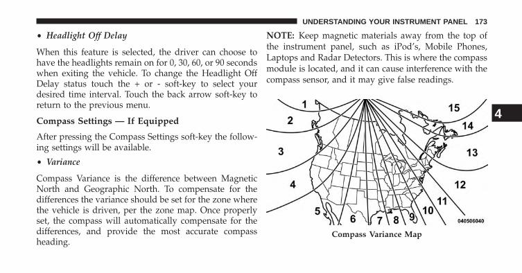
• Headlight Off Delay
When this feature is selected, the driver can choose tohave the headlights remain on for 0, 30, 60, or 90 secondswhen exiting the vehicle. To change the Headlight OffDelay status touch the + or - soft-key to select yourdesired time interval. Touch the back arrow soft-key toreturn to the previous menu.
Compass Settings — If Equipped
After pressing the Compass Settings soft-key the follow-ing settings will be available.
• Variance
Compass Variance is the difference between MagneticNorth and Geographic North. To compensate for thedifferences the variance should be set for the zone wherethe vehicle is driven, per the zone map. Once properlyset, the compass will automatically compensate for thedifferences, and provide the most accurate compassheading.
NOTE: Keep magnetic materials away from the top ofthe instrument panel, such as iPod’s, Mobile Phones,Laptops and Radar Detectors. This is where the compassmodule is located, and it can cause interference with thecompass sensor, and it may give false readings.
Compass Variance Map
4
UNDERSTANDING YOUR INSTRUMENT PANEL 173
• Perform Compass Calibration
Touch the Calibration soft-key to change this setting. Thiscompass is self-calibrating, which eliminates the need tomanually reset the compass. When the vehicle is new, thecompass may appear erratic and the EVIC will displayCAL until the compass is calibrated. You may alsocalibrate the compass by pressing the ON soft-key andcompleting one or more 360-degree turns (in an area freefrom large metal or metallic objects) until the CALindicator displayed in the EVIC turns off. The compasswill now function normally.
Audio
After pressing the Audio soft-key the following settingswill be available.
• Balance/Fade
When in this display you may adjust the Balance andFade settings.
• Equalizer
When in this display you may adjust the Bass, Mid andTreble settings. Adjust the settings with the + and – settingsoft-keys or by selecting any point on the scale between the+ and – soft-keys. Then touch the arrow back soft-key.
NOTE: Bass/Mid/Treble allow you to simply slide yourfinger up or down to change the setting as well as touchdirectly on the desired setting.
• Speed Adjusted Volume
This feature increases or decreases volume relative to vehiclespeed. To change the Speed Adjusted Volume touch the Off,1, 2 or 3 soft-key. Then touch the arrow back soft-key.
• Surround Sound
This feature provides simulated surround sound mode.To make your selection, touch the Surround Soundsoft-key, select On or Off followed by pressing the arrowback soft-key.
174 UNDERSTANDING YOUR INSTRUMENT PANEL
Phone/Bluetooth
After pressing the Phone/Bluetooth soft-key the follow-ing settings will be available:
• Paired Devices
This feature shows which phones are paired to the Phone /Bluetooth® system. For further information, refer to theUconnect® Supplement Manual.
SiriusXM Setup
After pressing the SIRIUS Setup soft-key the followingsettings will be available:
• Channel Skip
SiriusXM can be programmed to designate a group ofchannels that are the most desirable to listen to or toexclude undesirable channels while scanning. To makeyour selection, touch the Channel Skip soft-key, select thechannels you would like to skip followed by pressing thearrow back soft-key.
• Subscription Information
New vehicle purchasers or lessees will receive a freelimited time subscription to SiriusXM Satellite Radio withyour radio. Following the expiration of the free services, itwill be necessary to access the information on the Subscrip-tion Information screen in order to re-subscribe.
Touch the Subscription Info soft-key to access the Sub-scription Information screen.
Write down the SIRIUS ID numbers for your receiver. Toreactivate your service, either call the number listed onthe screen or visit the provider online.
NOTE: SiriusXM Travel Link is a separate subscriptionand is available for U.S. residents only.
4
UNDERSTANDING YOUR INSTRUMENT PANEL 175
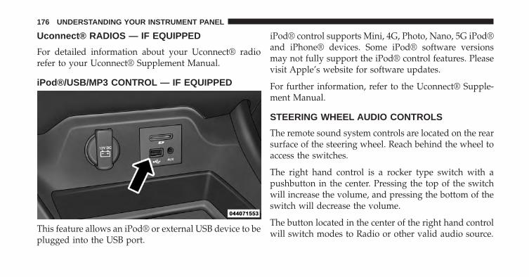
Uconnect® RADIOS — IF EQUIPPED
For detailed information about your Uconnect® radiorefer to your Uconnect® Supplement Manual.
iPod®/USB/MP3 CONTROL — IF EQUIPPED
This feature allows an iPod® or external USB device to beplugged into the USB port.
iPod® control supports Mini, 4G, Photo, Nano, 5G iPod®and iPhone® devices. Some iPod® software versionsmay not fully support the iPod® control features. Pleasevisit Apple’s website for software updates.
For further information, refer to the Uconnect® Supple-ment Manual.
STEERING WHEEL AUDIO CONTROLS
The remote sound system controls are located on the rearsurface of the steering wheel. Reach behind the wheel toaccess the switches.
The right hand control is a rocker type switch with apushbutton in the center. Pressing the top of the switchwill increase the volume, and pressing the bottom of theswitch will decrease the volume.
The button located in the center of the right hand controlwill switch modes to Radio or other valid audio source.
176 UNDERSTANDING YOUR INSTRUMENT PANEL
The left hand control is a rocker type switch with apushbutton in the center. The function of the left handcontrol is different depending on which mode you are in.
The following describes the left hand control operation ineach mode.
Radio Operation
Pressing the top of the switch will SEEK up for the nextlistenable station and pressing the bottom of the switchwill SEEK down for the next listenable station.
The button located in the center of the left hand controlwill tune to the next pre-set station that you haveprogrammed in the radio pre-set pushbuttons.
RADIO ANTENNA
The radio antenna is located in the windshield.
RADIO OPERATION AND MOBILE PHONES
Under certain conditions, the mobile phone being on inyour vehicle can cause erratic or noisy performance fromyour radio. This condition may be lessened or eliminatedby relocating the mobile phone antenna. This condition isnot harmful to the radio. If your radio performance doesnot satisfactorily “clear” by the repositioning of theantenna, it is recommended that the radio volume beturned down or off during mobile phone operation whennot using Uconnect® (if equipped).
CLIMATE CONTROLS
The Climate Control System allows you to regulate thetemperature, amount, and direction of air circulatingthroughout the vehicle. The controls are located on theinstrument panel below the radio.
4
UNDERSTANDING YOUR INSTRUMENT PANEL 177
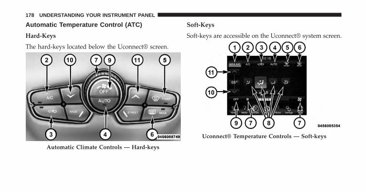
Automatic Temperature Control (ATC)
Hard-Keys
The hard-keys located below the Uconnect® screen.
Soft-Keys
Soft-keys are accessible on the Uconnect® system screen.
Automatic Climate Controls — Hard-keys
Uconnect® Temperature Controls — Soft-keys
178 UNDERSTANDING YOUR INSTRUMENT PANEL
Button Descriptions (Applies To Both Hard-keys AndSoft-keys)
1. MAX A/C Button
Press and release to change the current setting, theindicator illuminates when MAX A/C is ON. Performingthis function again will cause the MAX A/C operation toswitch into manual mode and the MAX A/C indicatorwill turn off.
2. A/C Button
Press and release to change the current setting, theindicator illuminates when A/C is ON. Performing thisfunction again will cause the A/C operation to switchinto manual mode and the A/C indicator will turn off.
3. Recirculation Button
Press and release to change the current setting, theindicator illuminates when ON.
4. AUTO Temperature Control
Controls airflow temperature, distribution, volume, andthe amount of air recirculation automatically. Press andrelease to select. Refer to “Automatic Operation” formore information. Performing this function will causethe ATC to switch between manual mode and automaticmodes.
4
UNDERSTANDING YOUR INSTRUMENT PANEL 179
5. Front Defrost Button
Press and release to change the current airflow setting toDefrost mode. The indicator illuminates when this fea-ture is ON. Performing this function will cause the ATCto switch into manual mode. The blower speed mayincrease when Defrost mode is selected. If the frontdefrost mode is turned off the climate system will returnthe previous setting.
6. Rear Defrost Button
Press and release this button to turn on the rear windowdefroster and the heated outside mirrors (if equipped).An indicator will illuminate when the rear windowdefroster is on. The rear window defroster automaticallyturns off after 10 minutes.
CAUTION!
Failure to follow these cautions can cause damage tothe heating elements:• Use care when washing the inside of the rear
window. Do not use abrasive window cleaners onthe interior surface of the window. Use a soft clothand a mild washing solution, wiping parallel to theheating elements. Labels can be peeled off aftersoaking with warm water.
• Do not use scrapers, sharp instruments, or abrasivewindow cleaners on the interior surface of thewindow.
• Keep all objects a safe distance from the window.
180 UNDERSTANDING YOUR INSTRUMENT PANEL
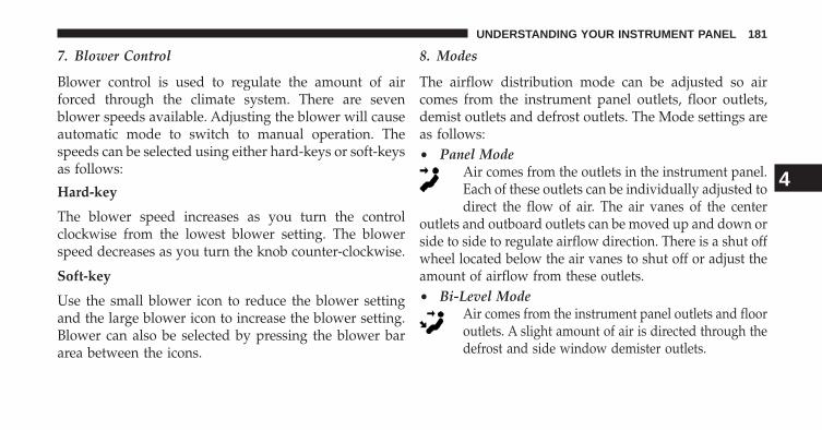
7. Blower Control
Blower control is used to regulate the amount of airforced through the climate system. There are sevenblower speeds available. Adjusting the blower will causeautomatic mode to switch to manual operation. Thespeeds can be selected using either hard-keys or soft-keysas follows:
Hard-key
The blower speed increases as you turn the controlclockwise from the lowest blower setting. The blowerspeed decreases as you turn the knob counter-clockwise.
Soft-key
Use the small blower icon to reduce the blower settingand the large blower icon to increase the blower setting.Blower can also be selected by pressing the blower bararea between the icons.
8. Modes
The airflow distribution mode can be adjusted so aircomes from the instrument panel outlets, floor outlets,demist outlets and defrost outlets. The Mode settings areas follows:• Panel Mode
Air comes from the outlets in the instrument panel.Each of these outlets can be individually adjusted todirect the flow of air. The air vanes of the center
outlets and outboard outlets can be moved up and down orside to side to regulate airflow direction. There is a shut offwheel located below the air vanes to shut off or adjust theamount of airflow from these outlets.• Bi-Level Mode
Air comes from the instrument panel outlets and flooroutlets. A slight amount of air is directed through thedefrost and side window demister outlets.
4
UNDERSTANDING YOUR INSTRUMENT PANEL 181
NOTE: BI-LEVEL mode is designed under comfort con-ditions to provide cooler air out of the panel outlets andwarmer air from the floor outlets.• Floor Mode
Air comes from the floor outlets. A slight amountof air is directed through the defrost and sidewindow demister outlets.
• Mix ModeAir comes from the floor, defrost and side windowdemist outlets. This mode works best in cold orsnowy conditions.
9. Climate Control OFF Button
Press and release this button to turn the Climate ControlON/OFF.
10. Temperature Control Down Button
Push the button for cooler temperature settings.
11. Temperature Control Up Button
Push the button for warmer temperature settings.
Automatic Operation
1. Press the AUTO hard-key or soft-key button on theAutomatic Temperature Control (ATC) Panel.
2. Next, adjust the temperature you would like thesystem to maintain by adjusting the driver and pas-senger temperature hard or soft control buttons. Oncethe desired temperature is displayed, the system willachieve and automatically maintain that comfort level.
3. When the system is set up for your comfort level, it isnot necessary to change the settings. You will experi-ence the greatest efficiency by simply allowing thesystem to function automatically.
182 UNDERSTANDING YOUR INSTRUMENT PANEL
NOTE:
• It is not necessary to move the temperature settings forcold or hot vehicles. The system automatically adjuststhe temperature, mode, and blower speed to providecomfort as quickly as possible.
• The temperature can be displayed in U.S. or Metricunits by selecting the US/M customer-programmablefeature. Refer to the “Uconnect® System Settings” inthis section of the manual.
To provide you with maximum comfort in the Automaticmode, during cold start-ups the blower fan will remainon low until the engine warms up. The blower willincrease in speed and transition into Auto mode.
Recirculation Control
When outside air contains smoke, odors, or high humid-ity, or if rapid cooling is desired, you may wish torecirculate interior air by pressing the RECIRCULATIONcontrol button. Recirculation mode should only be usedtemporarily. The recirculation LED will illuminate on theblower control knob when this button is selected. Pushthe button a second time to turn off the Recirculationmode LED and allow outside air into the vehicle.
NOTE: In cold weather, use of Recirculation mode maylead to excessive window fogging. The Recirculationmode is not allowed in Defrost mode to improve windowclearing operation. Recirculation will be disabled auto-matically if these modes are selected.
4
UNDERSTANDING YOUR INSTRUMENT PANEL 183
Summer Operation
The engine cooling system must be protected with ahigh-quality antifreeze coolant to provide proper corro-sion protection and to protect against engine overheating.A solution of 50% ethylene glycol antifreeze coolant and50% water is recommended. Refer to “Maintenance Pro-cedures” in “Maintaining Your Vehicle” for proper cool-ant selection.
Winter Operation
To ensure the best possible heater and defroster perfor-mance, make sure the engine cooling system is function-ing properly and the proper amount, type, and concen-tration of coolant is used. Refer to “MaintenanceProcedures” in “Maintaining Your Vehicle” for propercoolant selection. Use of the air Recirculation modeduring Winter months is not recommended because itmay cause window fogging.
Vacation/Storage
Any time you store your vehicle or keep it out of service(i.e., vacation) for two weeks or more, run the airconditioning system at idle for about five minutes infresh air with the blower setting in high. This will ensureadequate system lubrication to minimize the possibilityof compressor damage when the system is started again.
Window Fogging and Frosting
Vehicle windows tend to fog on the inside of the glass inmild, rainy and/or humid weather. Windows may froston the inside of the glass in very cold weather. To clearthe windows, select Defrost or Mix mode and increasethe front blower speed. Do not use the Recirculationmode without A/C for long periods, as fogging mayoccur.
184 UNDERSTANDING YOUR INSTRUMENT PANEL
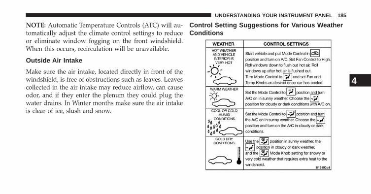
NOTE: Automatic Temperature Controls (ATC) will au-tomatically adjust the climate control settings to reduceor eliminate window fogging on the front windshield.When this occurs, recirculation will be unavailable.
Outside Air Intake
Make sure the air intake, located directly in front of thewindshield, is free of obstructions such as leaves. Leavescollected in the air intake may reduce airflow, can causeodor, and if they enter the plenum they could plug thewater drains. In Winter months make sure the air intakeis clear of ice, slush and snow.
Control Setting Suggestions for Various WeatherConditions
4
UNDERSTANDING YOUR INSTRUMENT PANEL 185

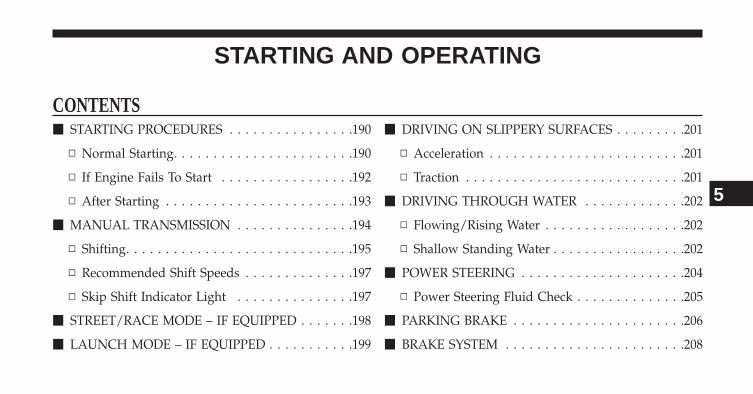
STARTING AND OPERATING
CONTENTS� STARTING PROCEDURES . . . . . . . . . . . . . . . .190
▫ Normal Starting. . . . . . . . . . . . . . . . . . . . . . .190
▫ If Engine Fails To Start . . . . . . . . . . . . . . . . .192
▫ After Starting . . . . . . . . . . . . . . . . . . . . . . . .193
� MANUAL TRANSMISSION . . . . . . . . . . . . . . .194
▫ Shifting. . . . . . . . . . . . . . . . . . . . . . . . . . . . .195
▫ Recommended Shift Speeds . . . . . . . . . . . . . .197
▫ Skip Shift Indicator Light . . . . . . . . . . . . . . .197
� STREET/RACE MODE – IF EQUIPPED . . . . . . .198
� LAUNCH MODE – IF EQUIPPED . . . . . . . . . . .199
� DRIVING ON SLIPPERY SURFACES . . . . . . . . .201
▫ Acceleration . . . . . . . . . . . . . . . . . . . . . . . . .201
▫ Traction . . . . . . . . . . . . . . . . . . . . . . . . . . . .201
� DRIVING THROUGH WATER . . . . . . . . . . . . .202
▫ Flowing/Rising Water . . . . . . . . . . . . . . . . . .202
▫ Shallow Standing Water . . . . . . . . . . . . . . . . .202
� POWER STEERING . . . . . . . . . . . . . . . . . . . . .204
▫ Power Steering Fluid Check . . . . . . . . . . . . . .205
� PARKING BRAKE . . . . . . . . . . . . . . . . . . . . . .206
� BRAKE SYSTEM . . . . . . . . . . . . . . . . . . . . . . .208
5
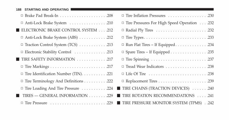
▫ Brake Pad Break-In . . . . . . . . . . . . . . . . . . . .208
▫ Anti-Lock Brake System . . . . . . . . . . . . . . . .210
� ELECTRONIC BRAKE CONTROL SYSTEM . . . .212
▫ Anti-Lock Brake System (ABS) . . . . . . . . . . . .212
▫ Traction Control System (TCS) . . . . . . . . . . . .213
▫ Electronic Stability Control . . . . . . . . . . . . . .213
� TIRE SAFETY INFORMATION . . . . . . . . . . . . .217
▫ Tire Markings . . . . . . . . . . . . . . . . . . . . . . . .217
▫ Tire Identification Number (TIN). . . . . . . . . . .221
▫ Tire Terminology And Definitions . . . . . . . . . .222
▫ Tire Loading And Tire Pressure . . . . . . . . . . .224
� TIRES — GENERAL INFORMATION . . . . . . . .229
▫ Tire Pressure . . . . . . . . . . . . . . . . . . . . . . . .229
▫ Tire Inflation Pressures . . . . . . . . . . . . . . . . .230
▫ Tire Pressures For High Speed Operation . . . .232
▫ Radial Ply Tires . . . . . . . . . . . . . . . . . . . . . .232
▫ Tire Types . . . . . . . . . . . . . . . . . . . . . . . . . . .233
▫ Run Flat Tires – If Equipped . . . . . . . . . . . . . .234
▫ Spare Tires – If Equipped . . . . . . . . . . . . . . . .235
▫ Tire Spinning . . . . . . . . . . . . . . . . . . . . . . . .237
▫ Tread Wear Indicators . . . . . . . . . . . . . . . . . .238
▫ Life Of Tire . . . . . . . . . . . . . . . . . . . . . . . . .238
▫ Replacement Tires . . . . . . . . . . . . . . . . . . . . .239
� TIRE CHAINS (TRACTION DEVICES) . . . . . . .240
� TIRE ROTATION RECOMMENDATIONS . . . . .241
� TIRE PRESSURE MONITOR SYSTEM (TPMS) . .242
188 STARTING AND OPERATING
▫ Premium System . . . . . . . . . . . . . . . . . . . . . .245
� FUEL REQUIREMENTS . . . . . . . . . . . . . . . . . .247
▫ 8.4L Engine . . . . . . . . . . . . . . . . . . . . . . . . . .247
▫ Reformulated Gasoline . . . . . . . . . . . . . . . . .248
▫ Gasoline/Oxygenate Blends . . . . . . . . . . . . . .248
▫ E-85 Usage In Non-Flex Fuel Vehicles . . . . . . .249
▫ MMT In Gasoline . . . . . . . . . . . . . . . . . . . . .249
▫ Materials Added To Fuel . . . . . . . . . . . . . . . .250
▫ Fuel System Cautions. . . . . . . . . . . . . . . . . . .250
▫ Carbon Monoxide Warnings . . . . . . . . . . . . .251
� ADDING FUEL . . . . . . . . . . . . . . . . . . . . . . . .251
▫ Emergency Fuel Filler Door Release. . . . . . . . .253
� TRAILER TOWING . . . . . . . . . . . . . . . . . . . . .255
� RECREATIONAL TOWING (BEHINDMOTORHOME, ETC.) . . . . . . . . . . . . . . . . . . .256
▫ Towing This Vehicle Behind Another Vehicle(Flat towing with all four wheels on theground) . . . . . . . . . . . . . . . . . . . . . . . . . . . .256
� GROUND CLEARANCE . . . . . . . . . . . . . . . . .257
5
STARTING AND OPERATING 189

STARTING PROCEDURES
Before starting your vehicle, adjust your seat, adjust theinside and outside mirrors, fasten your seat belt, and ifpresent, instruct any other occupant to buckle their seatbelt.
WARNING!
Never leave children alone in a vehicle. Leavingunattended children in a vehicle is dangerous for anumber of reasons. A child or others could be seri-ously or fatally injured. Do not leave the key fob inor near the vehicle (or in a location accessible tochildren), and do not leave a vehicle equipped withKeyless Enter-N-Go™ in the ACC or ON/RUN mode.A child could operate power windows, other con-trols, or move the vehicle.
CAUTION!
Long periods of engine idling, especially at higherthan normal engine idle speeds, can cause excessiveexhaust temperatures, which can damage your ve-hicle. Do not leave your vehicle unattended with theengine running.
Normal Starting
CAUTION!
The engine in your vehicle is designed for operationdown to 0°F (-18°C). Starting the engine below 0°F(-18°C) coolant temperature creates a potential forscuffing or seizing of internal components in thishigh performance engine. To prevent engine damage,do not start the engine at temperatures below 0°F(-18°C).
190 STARTING AND OPERATING
NOTE:
• You must disarm the security system in order to startthe engine. Refer to “Security Alarm System” in“Things To Know Before Starting Your Vehicle” forfurther information.
• Normal starting of either a cold or a warm engine doesnot require pumping or pressing the accelerator pedal.However, if the engine has not started within threeseconds, slightly press the accelerator pedal whilecontinuing to crank. If the engine fails to start within15 seconds, wait five seconds, then repeat the “NormalStarting” procedure.
To Start The Engine:
1. Fully apply the parking brake.
2. Press the clutch pedal to the floor.
NOTE: The engine will not start unless the clutch pedalis pressed to the floor.
3. Place the shift lever in NEUTRAL.
4. Press the red ENGINE START/STOP button locatedon the instrument panel. Release the button when theengine starts.
5
STARTING AND OPERATING 191
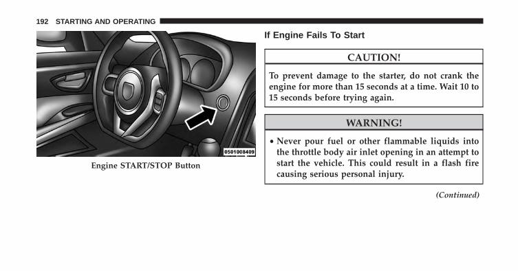
If Engine Fails To Start
CAUTION!
To prevent damage to the starter, do not crank theengine for more than 15 seconds at a time. Wait 10 to15 seconds before trying again.
WARNING!
• Never pour fuel or other flammable liquids intothe throttle body air inlet opening in an attempt tostart the vehicle. This could result in a flash firecausing serious personal injury.
(Continued)
Engine START/STOP Button
192 STARTING AND OPERATING
WARNING! (Continued)• Do not attempt to push or tow your vehicle to get it
started. Unburned fuel could enter the catalyticconverter and once the engine has started, igniteand damage the converter and vehicle. If the ve-hicle has a discharged battery, booster cables maybe used to obtain a start from a booster battery orthe battery in another vehicle. This type of start canbe dangerous if done improperly, so follow thisprocedure carefully. Refer to “Jump Starting” in“What To Do In Emergencies” for further informa-tion.
If the engine is flooded, it may start to run, but not haveenough power to continue running when the ENGINESTART button is released. If this occurs, continue crank-ing up to 15 seconds with the accelerator pedal pushedall the way to the floor. Release the accelerator pedal andthe ENGINE START button once the engine is runningsmoothly.
If the engine shows no sign of starting after two 15second periods of cranking with the accelerator pedalheld to the floor, the “Normal Starting” procedure shouldbe repeated.
After Starting
The idle speed is controlled automatically and it willdecrease as the engine warms up.
5
STARTING AND OPERATING 193
MANUAL TRANSMISSION
NOTE: The parking brake should be engaged and theshift lever placed into REVERSE before leaving thevehicle, especially when parked on an incline.
Your vehicle is equipped with a high torque capacity dualdisc clutch. The clutch pedal must be fully pressed to thefloor during each shift. As you release the clutch pedal,lightly press the accelerator pedal.
CAUTION!
• Never drive with your foot resting on the clutchpedal, or try to hold the vehicle on a hill with theclutch pedal partially engaged, as this will causeabnormal wear on the clutch.
(Continued)
CAUTION! (Continued)• Failure to press the clutch pedal fully to the floor
may cause increased shift efforts, and may result indamage to the clutch and transmission.
• Do not rest your hand on the shift lever whiledriving, as this may result in transmission damage.
• Do not attempt to shift the transmission if the rearwheels are spinning due to loss of traction. Dam-age to the transmission may occur.
Ensure the transmission is in first gear when movingforward from a standing position.
CAUTION!
Failure to start out in first gear when moving forwardfrom a starting position may result in damage to theclutch.
194 STARTING AND OPERATING
Shifting
Fully press the clutch pedal and lift your foot off theaccelerator pedal before shifting gears. As you release theclutch pedal, lightly press the accelerator pedal. Damageto the transmission or clutch may occur if you do notfully press the clutch pedal and lift off of the acceleratorpedal when shifting.
The six-speed manual transmission has a spring thatcenters the shift lever near third and fourth gear. Thisspring helps you know which gear you are in when youare shifting. Be careful when shifting from first to secondor downshifting from sixth to fifth.
The spring will try to pull the shift lever toward third andfourth gear. Make sure you move the shift lever intosecond or fifth gear. If you let the shift lever move in thedirection of the pulling, you may end shifting from firstto fourth or from sixth to third gear.
You will find it easier to use only the lower gears for mostcity driving. For steady highway driving with lightaccelerations, sixth gear is recommended.
Never drive with your foot resting on the clutch pedal, ortry to hold the vehicle on a hill with the clutch pedalpartially engaged. This will cause abnormal wear on theclutch.
Never shift into REVERSE until the vehicle has come to acomplete stop.
5
STARTING AND OPERATING 195
NOTE:
• Your vehicle is equipped with a transmission reverseinhibitor system. When vehicle speed is greater than3 mph (5 km/h), the reverse inhibitor activates to helpprevent shifts into REVERSE. When at a complete stop,you may notice light shift efforts into REVERSE withthe ignition in the ON position, and increased shiftefforts into REVERSE with the ignition in the OFFposition. This is normal operation of the transmissionreverse inhibitor system.
• Shifting gears during cold weather may require anincreased effort until the transmission lubricant iswarm. This is normal and not harmful to the transmis-sion.
• Due to the high performance nature of your drivetrain,a certain amount of noise from the transmission isnormal. This noise can be most noticeable when thevehicle is idling in NEUTRAL with the clutch engaged(clutch pedal released), but it may also be heard whendriving. The noise may also be more noticeable whenthe transmission is warm. This noise is normal and isnot an indication of a problem with your clutch ortransmission.
• You must always use first gear (or Reverse) whenstarting from a standing position.
CAUTION!
Always make sure the vehicle comes to a completestop before shifting into REVERSE. Failure to do somay result in transmission damage.
196 STARTING AND OPERATING
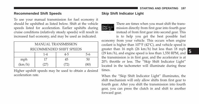
Recommended Shift Speeds
To use your manual transmission for fuel economy itshould be upshifted as listed below. Shift at the vehiclespeeds listed for acceleration. Earlier upshifts duringcruise conditions (relatively steady speeds) will result inincreased fuel economy, and may be used as indicated.
MANUAL TRANSMISSIONRECOMMENDED SHIFT SPEEDS
1-4 4-5 5-6mph 17 45 50
(km/h) (27) (72) (80)
Higher upshift speeds may be used to obtain a desiredacceleration rate.
Skip Shift Indicator Light
There are times when you must shift the trans-mission directly from first gear into fourth gearinstead of from first gear into second gear. Thisis to help you get the best possible fuel
economy from your vehicle. This occurs when enginecoolant is higher than 107°F (42°C), and vehicle speed isgreater than 16 mph (26 km/h) but less than 18 mph(29 km/h), and engine speed is less than 1,550 RPM, andthe transmission is in first gear, and the accelerator is at20% throttle or less. The “Skip Shift Indicator Light”located in the tachometer will illuminate during thesetimes.
When the “Skip Shift Indicator Light” illuminates, theshift mechanism will only allow shifts from first gear tofourth gear. After you shift the transmission into fourthgear, you can press the clutch in and shift to anotherforward gear.
5
STARTING AND OPERATING 197
Downshifting - Proper downshifting will improve fueleconomy and prolong engine life.
To maintain a safe speed and prolong brake life, down-shift to maintain a safe speed when descending a steepgrade.
CAUTION!
If you skip more than one gear while downshiftingor downshift at too high a vehicle speed, you coulddamage the engine, transmission, or clutch.
WARNING!
Skipping more than one gear while downshifting,could cause you to lose control of your vehicle. Youcould have a collision.
STREET/RACE MODE – IF EQUIPPED
This vehicle is equipped with an electronic controlleddamping system. This system allows for a street suspen-sion damping setting or a firmer race suspension damp-ing setting. When in street mode the system automati-cally shifts the suspension dampers to the firmer Racedamping setting during some hard acceleration andbraking situations. The system also reduces body roll andpitch in many driving situations including accelerationand braking. There are two modes of operation:
NOTE: With the ignition in the ON/RUN position, thesuspension damping system will be in the last mode thesystem was in when the vehicle was turned off. Thedriver can select either Street or Race damping mode atany time.
• Street Mode — This mode will give a sporty, butcomfortable ride. Within this mode, the suspensionwill adapt to the vehicle inputs, including vehicle
198 STARTING AND OPERATING
speed, braking and acceleration. This mode is driverselectable when the vehicle is placed in STREET mode(press the “STREET” button on the Instrument Panel).This mode will set the suspension for maximumperformance handling and is intended for a smootherride on the various types of pavement and roadconditions while still providing damping levels appro-priate extreme capabilities.
• Race Mode — This mode is driver selectable when thevehicle is placed in RACE mode (press the “RACE”button on the Instrument Panel). This mode is for trackuse only and will supply maximum grip to the tires.
NOTE: The RACE setting will provide a firmer ride.
• When RACE mode is enabled, a Shock symbol with“RACE” next to it will light up in the instrumentcluster.
LAUNCH MODE – IF EQUIPPED
This system maximizes acceleration traction for straightline racing.
1. Bring the vehicle to complete stop on a level tracksurface with the engine running.
2. Set the steering wheel for straight ahead driving.
3. Fully depress the clutch and select the first gearposition.
4. Press and release the “LAUNCH” Button (Located onthe steering wheel controls).
5
STARTING AND OPERATING 199
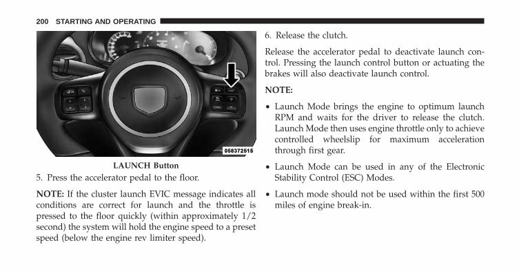
5. Press the accelerator pedal to the floor.
NOTE: If the cluster launch EVIC message indicates allconditions are correct for launch and the throttle ispressed to the floor quickly (within approximately 1/2second) the system will hold the engine speed to a presetspeed (below the engine rev limiter speed).
6. Release the clutch.
Release the accelerator pedal to deactivate launch con-trol. Pressing the launch control button or actuating thebrakes will also deactivate launch control.
NOTE:
• Launch Mode brings the engine to optimum launchRPM and waits for the driver to release the clutch.Launch Mode then uses engine throttle only to achievecontrolled wheelslip for maximum accelerationthrough first gear.
• Launch Mode can be used in any of the ElectronicStability Control (ESC) Modes.
• Launch mode should not be used within the first 500miles of engine break-in.
LAUNCH Button
200 STARTING AND OPERATING
DRIVING ON SLIPPERY SURFACES
Acceleration
WARNING!
Rapid acceleration on slippery surfaces is dangerous.You could lose control of the vehicle and possiblyhave a collision. Accelerate slowly and carefullywhenever there is likely to be poor traction (ice,snow, wet, mud, loose sand, etc.).
Traction
When driving on wet or slushy roads, it is possible for awedge of water to build up between the tire and roadsurface. This is hydroplaning and may cause partial orcomplete loss of vehicle control and stopping ability. Toreduce this possibility, the following precautions should beobserved:
1. Slow down during rainstorms or when roads are slushy.
2. Slow down if road has standing water or puddles.
CAUTION!
Driving your vehicle through deep puddles at speedsover 5 mph (8 km/h), may cause water to be ingestedinto the engine. This can cause severe engine dam-age.
3. Replace tires when tread wear indicators first becomevisible.
4. Keep tires properly inflated.
5. Maintain enough distance between your vehicle andthe vehicle in front of you to avoid a collision in asudden stop.
5
STARTING AND OPERATING 201
DRIVING THROUGH WATER
Driving through water more than a few inches/centimeters deep will require extra caution to ensuresafety and prevent damage to your vehicle.
Flowing/Rising Water
WARNING!
Do not drive on or across a road or path where wateris flowing and/or rising (as in storm run-off). Flow-ing water can wear away the road or path’s surfaceand cause your vehicle to sink into deeper water.Furthermore, flowing and/or rising water can carryyour vehicle away swiftly. Failure to follow thiswarning may result in injuries that are serious orfatal to you, your passengers, and others around you.
Shallow Standing Water
Although your vehicle is capable of driving throughshallow standing water, consider the following Cautionand Warning before doing so.
CAUTION!
• Always check the depth of the standing waterbefore driving through it. Never drive throughstanding water that is deeper than the bottom ofthe tire rims mounted on the vehicle.
• Determine the condition of the road or the paththat is under water and if there are any obstacles inthe way before driving through the standing water.
• Do not exceed 5 mph (8 km/h) when drivingthrough standing water. This will minimize waveeffects.
(Continued)
202 STARTING AND OPERATING
CAUTION! (Continued)• Driving through standing water may cause damage
to your vehicle’s drivetrain components. Alwaysinspect your vehicle’s fluids (i.e., engine oil, trans-mission, axle, etc.) for signs of contamination (i.e.,fluid that is milky or foamy in appearance) afterdriving through standing water. Do not continue tooperate the vehicle if any fluid appears contami-nated, as this may result in further damage. Suchdamage is not covered by the New Vehicle LimitedWarranty.
• Getting water inside your vehicle’s engine cancause it to lock up and stall out, and cause seriousinternal damage to the engine. Such damage is notcovered by the New Vehicle Limited Warranty.
WARNING!
• Driving through standing water limits your vehi-cle’s traction capabilities. Do not exceed 5 mph(8 km/h) when driving through standing water.
• Driving through standing water limits your vehi-cle’s braking capabilities, which increases stoppingdistances. Therefore, after driving through stand-ing water, drive slowly and lightly press on thebrake pedal several times to dry the brakes.
• Failure to follow these warnings may result ininjuries that are serious or fatal to you, your pas-sengers, and others around you.
5
STARTING AND OPERATING 203
POWER STEERING
The standard power steering system will give you goodvehicle response and increased ease of maneuverabilityin tight spaces. The system will provide mechanicalsteering capability if power assist is lost.
If for some reason the power assist is interrupted, it willstill be possible to steer your vehicle. Under these condi-tions, you will observe a substantial increase in steeringeffort, especially at very low vehicle speeds and duringparking maneuvers.
NOTE:
• Increased noise levels at the end of the steering wheeltravel are considered normal and do not indicate thatthere is a problem with the power steering system.
• Upon initial start-up in cold weather, the power steer-ing pump may make noise for a short amount of time.This is due to the cold, thick fluid in the steeringsystem. This noise should be considered normal, and itdoes not in any way damage the steering system.
WARNING!
Continued operation with reduced power steeringassist could pose a safety risk to yourself and others.Service should be obtained as soon as possible.
CAUTION!
Prolonged operation of the steering system at the endof the steering wheel travel will increase the steeringfluid temperature and it should be avoided whenpossible. Damage to the power steering pump mayoccur.
204 STARTING AND OPERATING
Power Steering Fluid Check
Checking the power steering fluid level at a definedservice interval is not required. The fluid should only bechecked if a leak is suspected, abnormal noises areapparent, and/or the system is not functioning as antici-pated. Coordinate inspection efforts through an autho-rized dealer.
CAUTION!
Do not use chemical flushes in your power steeringsystem as the chemicals can damage your powersteering components. Such damage is not covered bythe New Vehicle Limited Warranty.
WARNING!
Fluid level should be checked on a level surface andwith the engine off to prevent injury from movingparts and to ensure accurate fluid level reading. Donot overfill. Use only manufacturer’s recommendedpower steering fluid.
If necessary, add fluid to restore to the proper indicatedlevel. With a clean cloth, wipe any spilled fluid from allsurfaces. Refer to “Fluids, Lubricants, and GenuineParts” in “Maintaining Your Vehicle” for further informa-tion.
5
STARTING AND OPERATING 205
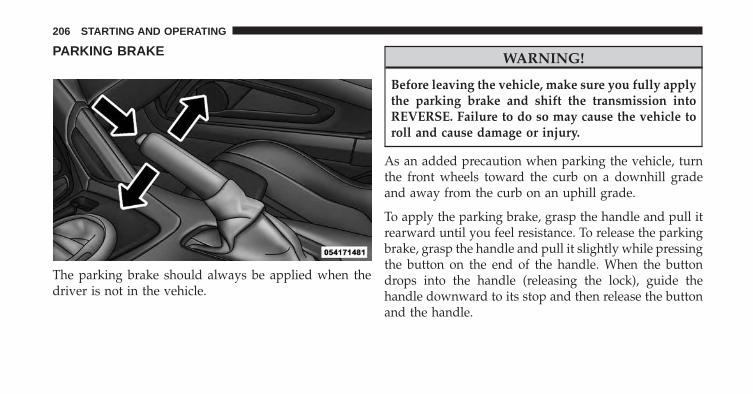
PARKING BRAKE
The parking brake should always be applied when thedriver is not in the vehicle.
WARNING!
Before leaving the vehicle, make sure you fully applythe parking brake and shift the transmission intoREVERSE. Failure to do so may cause the vehicle toroll and cause damage or injury.
As an added precaution when parking the vehicle, turnthe front wheels toward the curb on a downhill gradeand away from the curb on an uphill grade.
To apply the parking brake, grasp the handle and pull itrearward until you feel resistance. To release the parkingbrake, grasp the handle and pull it slightly while pressingthe button on the end of the handle. When the buttondrops into the handle (releasing the lock), guide thehandle downward to its stop and then release the buttonand the handle.
206 STARTING AND OPERATING
The “Brake System Warning Light” in the instrumentcluster will turn on when the ignition is in the ON/RUNposition and the parking brake is applied.
NOTE: This light only shows that the parking brake isapplied or a brake/ABS system fault. It does not showthe degree of brake application. If the “Brake SystemWarning Light” is illuminated when the parking brake isnot applied please see your authorized dealer.
WARNING!
• Never leave children alone in a vehicle. Leavingchildren in a vehicle unattended is dangerous for anumber of reasons. A child or others could beinjured seriously or fatally. Do not leave the keyfob in or near the vehicle (or in a location accessibleto children), and do not leave a vehicle equippedwith Keyless Enter-N-Go in the ACC or ON/RUNmode. A child could operate power windows, othercontrols, or move the vehicle.
• Ensure the parking brake is fully disengaged be-fore driving. Failure to do so can lead to brakefailure, and an accident.
5
STARTING AND OPERATING 207
BRAKE SYSTEM
Your vehicle is equipped with dual hydraulicbrake systems. If either of the two hydraulicsystems loses normal capability, the remainingsystem will still function. However, there will
be some loss of overall braking effectiveness. You maynotice increased pedal travel during application, greaterpedal force required to slow or stop, and potentialactivation of the “Brake System Warning Light.”
In the event power assist is lost for any reason (i.e.,repeated brake applications with the engine off) thebrakes will still function. However, the effort required tobrake the vehicle will be much greater than that requiredwith the power system operating.
Brake Pad Break-In
NOTE: Your vehicle is equipped with a high perfor-mance braking system. The brake pads are a semi-metallic compound, which offer superior fade resistancefor consistent operation. A compromise to using this typeof brake pad is that the brakes may squeal slightly undercertain weather and operating conditions (.i.e., duringlight brake applications).
The brakes on your new vehicle do not require a longbreak-in period. However, you should avoid repeatedhard brake applications from high speeds during initialbreak-in. In addition, you should avoid severe brakeloading, such as may be encountered when descendinglong mountain grades.
208 STARTING AND OPERATING
Safe Operating Tips
WARNING!
To use your brakes and accelerator more safely,follow these tips:• Do not “ride” the brakes by resting your foot on the
pedal. This could overheat the brakes and result inunpredictable braking action, longer stopping dis-tances, or brake damage.
• When descending mountains or hills, repeatedbraking can cause brake fade with loss of brakingcontrol. Avoid repeated heavy braking by down-shifting the transmission whenever possible.
(Continued)
WARNING! (Continued)• Do not drive too fast for road conditions, especially
when roads are wet or slushy. A wedge of water canbuild up between the tire tread and the road. Thishydroplaning action can cause loss of traction,braking ability, and control.
• After going through deep water or a car wash,brakes may become wet, resulting in decreasedperformance and unpredictable braking action.Dry the brakes by gentle, intermittent pedal actionwhile driving at very slow speeds.
5
STARTING AND OPERATING 209
Anti-Lock Brake System
The Anti-Lock Brake System (ABS) is designed to aid thedriver in maintaining vehicle control under adverse brak-ing conditions. The system operates with a separate com-puter to modulate hydraulic pressure to prevent wheellock-up and help avoid skidding on slippery surfaces.
NOTE: During severe braking conditions, a pulsing sen-sation may occur and a clicking noise will be heard. Thisis normal, indicating that the ABS is functioning.
The ABS conducts a low-speed self-test at approximately12 mph (20 km/h). If you have your foot lightly on thebrake pedal while this test is occurring, you may feel aslight pedal movement. The movement can be moreapparent on ice and snow and be considered normal.
The ABS pump motor runs during the self-test at 12 mph(20 km/h) and during an ABS stop. The pump motormakes a low humming noise during operation, which isnormal.
CAUTION!
The Anti-Lock Brake System is subject to possibledetrimental effects of electronic interference causedby improperly installed aftermarket radios or tele-phones.
WARNING!
• The Anti-Lock Brake System (ABS) contains so-phisticated electronic equipment that may be sus-ceptible to interference caused by improperly in-stalled or high output radio transmittingequipment. This interference can cause possibleloss of anti-lock braking capability. Installation ofsuch equipment should be performed by qualifiedprofessionals.
(Continued)
210 STARTING AND OPERATING
WARNING! (Continued)• Pumping of the Anti-Lock Brakes will diminish
their effectiveness and may lead to a collision.Pumping makes the stopping distance longer. Justpress firmly on your brake pedal when you need toslow down or stop.
• The Anti-Lock Brake System (ABS) cannot preventthe natural laws of physics from acting on thevehicle, nor can it increase braking or steeringefficiency beyond that afforded by the condition ofthe vehicle brakes and tires or the traction afforded.
• The Anti-Lock Brake System (ABS) cannot preventcollisions, including those resulting from excessivespeed in turns, following another vehicle tooclosely, or hydroplaning.
(Continued)
WARNING! (Continued)• The capabilities of an Anti-Lock Brake System
(ABS) equipped vehicle must never be exploited ina reckless or dangerous manner, that could jeopar-dize the user’s safety or the safety of others.
All vehicle wheels and tires must be the same size andtype as the original equipment and the tires must beproperly inflated to produce accurate signals for thecomputer.
WARNING!
Significant over or under-inflation of tires, or mixingsizes of tires or wheels on the vehicle can lead to lossof braking effectiveness.
5
STARTING AND OPERATING 211
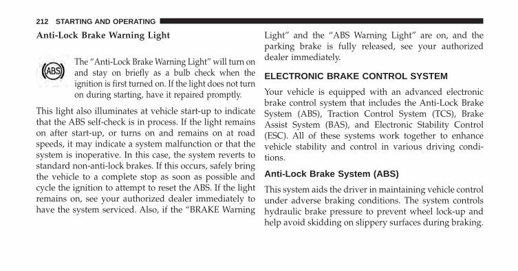
Anti-Lock Brake Warning Light
The “Anti-Lock Brake Warning Light” will turn onand stay on briefly as a bulb check when theignition is first turned on. If the light does not turnon during starting, have it repaired promptly.
This light also illuminates at vehicle start-up to indicatethat the ABS self-check is in process. If the light remainson after start-up, or turns on and remains on at roadspeeds, it may indicate a system malfunction or that thesystem is inoperative. In this case, the system reverts tostandard non-anti-lock brakes. If this occurs, safely bringthe vehicle to a complete stop as soon as possible andcycle the ignition to attempt to reset the ABS. If the lightremains on, see your authorized dealer immediately tohave the system serviced. Also, if the “BRAKE Warning
Light” and the “ABS Warning Light” are on, and theparking brake is fully released, see your authorizeddealer immediately.
ELECTRONIC BRAKE CONTROL SYSTEM
Your vehicle is equipped with an advanced electronicbrake control system that includes the Anti-Lock BrakeSystem (ABS), Traction Control System (TCS), BrakeAssist System (BAS), and Electronic Stability Control(ESC). All of these systems work together to enhancevehicle stability and control in various driving condi-tions.
Anti-Lock Brake System (ABS)
This system aids the driver in maintaining vehicle controlunder adverse braking conditions. The system controlshydraulic brake pressure to prevent wheel lock-up andhelp avoid skidding on slippery surfaces during braking.
212 STARTING AND OPERATING
WARNING!
The ABS cannot prevent the natural laws of physicsfrom acting on the vehicle, nor can it increase thetraction afforded by prevailing road conditions. TheABS cannot prevent collisions, including those re-sulting from excessive speed in turns, driving onvery slippery surfaces, or hydroplaning. The capa-bilities of an ABS-equipped vehicle must never beexploited in a reckless or dangerous manner whichcould jeopardize the user’s safety or the safety ofothers.
Traction Control System (TCS)
The TCS system monitors the amount of wheel spin ofeach driven wheel. If wheel spin is detected, brakepressure is applied to the slipping wheel(s) and enginepower is reduced to provide enhanced acceleration andstability.
Electronic Stability Control
In full on mode the TCS system enhances directionalcontrol and stability of the vehicle under various drivingconditions. The ESC corrects for oversteering and under-steering the vehicle by applying the brake of the appro-priate wheel. Engine power may also be reduced to assistin counteracting the condition of oversteer or understeerand help the vehicle maintain the desired path.
In full on mode ESC utilizes sensors in the vehicle todetermine the path that the driver intends to steer thevehicle and compares it to the actual path of the vehicle.When the actual path does not match the intended path,the ESC applies the brake of the appropriate wheel toassist in counteracting the condition of oversteer orundersteer.
• Oversteer – when the vehicle is turning more thanappropriate for the steering wheel position.
5
STARTING AND OPERATING 213
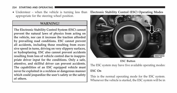
• Understeer – when the vehicle is turning less thanappropriate for the steering wheel position.
WARNING!
The Electronic Stability Control System (ESC) cannotprevent the natural laws of physics from acting onthe vehicle, nor can it increase the traction affordedby prevailing road conditions. ESC cannot preventall accidents, including those resulting from exces-sive speed in turns, driving on very slippery surfaces,or hydroplaning. ESC also cannot prevent accidentsresulting from loss of vehicle control due to inappro-priate driver input for the conditions. Only a safe,attentive, and skillful driver can prevent accidents.The capabilities of an ESC equipped vehicle mustnever be exploited in a reckless or dangerous mannerwhich could jeopardize the user’s safety or the safetyof others.
Electronic Stability Control (ESC) Operating Modes
The ESC system may have five available operating modes:
ESC On
This is the normal operating mode for the ESC system.Whenever the vehicle is started, the ESC system will be in
ESC Button
214 STARTING AND OPERATING
this mode. The ESC On mode should be used for mostdriving situations. The ESC should only be turned OFFfor specific reasons as noted in the following paragraphs.
ESC Full Off
The ESC Off mode is intended for off-highway or off-roaduse only and should not be used on any public roadways.In this mode, all TCS and ESC stability features are turnedOFF. To enter the “Full Off” mode, press and hold the “ESCOff” switch for five seconds while the vehicle is stoppedwith the engine running. After five seconds, a chime willsound, the “ESC Activation/Malfunction Indicator Light”will illuminate, and the �ESC OFF� message will display inthe vehicle cluster (left of the odometer). The “ESC OFF”message may appear in the Electronic Vehicle InformationCenter (EVIC). Refer to “Electronic Vehicle InformationCenter (EVIC)” in “Understanding Your Instrument Panel”for further information. To turn ESC ON again, momen-tarily press the “ESC Off” switch.
WARNING!
With the ESC switched OFF, the enhanced vehiclestability offered by ESC is unavailable. In an emer-gency evasive maneuver, the ESC system will notengage to assist in maintaining stability. The “FullOff” ESC mode is intended for off-highway or off-road only.
Sport Mode - If Equipped
Sport mode has reduced traction control and reducedstability control. To enter the “Sport Mode” mode, pressthe “ESC” switch once (located on the steering wheel).The “ESC Sport Light” will illuminate, and the �ESCSPORT� message will display in the vehicle cluster (left ofthe odometer). Refer to “Electronic Vehicle InformationCenter (EVIC)” in “Understanding Your InstrumentPanel” for further information.
5
STARTING AND OPERATING 215
Track Mode - If Equipped
Track Mode has no traction control and has reducedstability control. To enter the “Track Mode” mode, pressthe “ESC” switch twice. The “ESC Track Light” willilluminate, and the �ESC TRACK� message will display inthe vehicle cluster (left of the odometer). Refer to “Elec-tronic Vehicle Information Center (EVIC)” in “Under-standing Your Instrument Panel” for further information.
Rain Mode
Rain mode offers increased traction control and stabilitycontrol for low traction conditions such as wet roads, dryroads during cold temperatures, or when the driver
wants enhanced stability due to lack of familiarity orexperience with the vehicle’s response. To enter the “RainMode” mode, press the “ESC” switch three times. The“ESC Rain Light” will illuminate, and the �ESC RAIN�message will display in the vehicle cluster (left of theodometer). Refer to “Electronic Vehicle Information Cen-ter (EVIC)” in “Understanding Your Instrument Panel”for further information.
NOTE: Some models may not offer “Sport” or “Track”Mode.
216 STARTING AND OPERATING
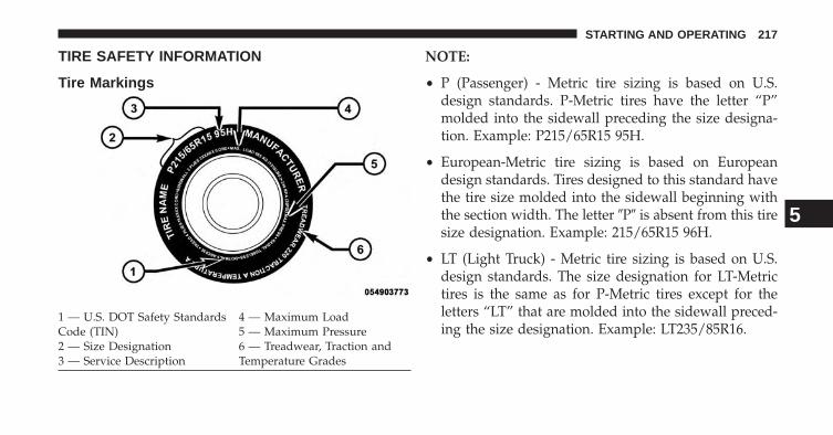
TIRE SAFETY INFORMATION
Tire Markings
NOTE:
• P (Passenger) - Metric tire sizing is based on U.S.design standards. P-Metric tires have the letter “P”molded into the sidewall preceding the size designa-tion. Example: P215/65R15 95H.
• European-Metric tire sizing is based on Europeandesign standards. Tires designed to this standard havethe tire size molded into the sidewall beginning withthe section width. The letter �P� is absent from this tiresize designation. Example: 215/65R15 96H.
• LT (Light Truck) - Metric tire sizing is based on U.S.design standards. The size designation for LT-Metrictires is the same as for P-Metric tires except for theletters “LT” that are molded into the sidewall preced-ing the size designation. Example: LT235/85R16.
1 — U.S. DOT Safety StandardsCode (TIN)
4 — Maximum Load
2 — Size Designation5 — Maximum Pressure
3 — Service Description6 — Treadwear, Traction andTemperature Grades
5
STARTING AND OPERATING 217
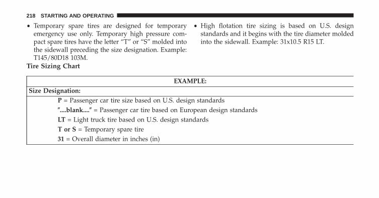
• Temporary spare tires are designed for temporaryemergency use only. Temporary high pressure com-pact spare tires have the letter “T” or “S” molded intothe sidewall preceding the size designation. Example:T145/80D18 103M.
• High flotation tire sizing is based on U.S. designstandards and it begins with the tire diameter moldedinto the sidewall. Example: 31x10.5 R15 LT.
Tire Sizing Chart
EXAMPLE:Size Designation:
P = Passenger car tire size based on U.S. design standards�....blank....� = Passenger car tire based on European design standardsLT = Light truck tire based on U.S. design standardsT or S = Temporary spare tire31 = Overall diameter in inches (in)
218 STARTING AND OPERATING
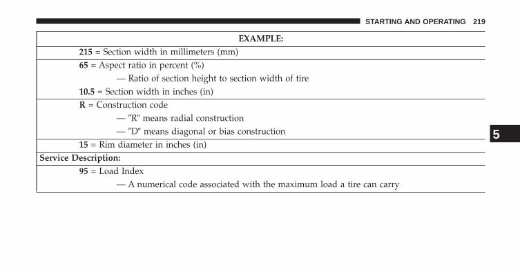
EXAMPLE:215 = Section width in millimeters (mm)65 = Aspect ratio in percent (%)
— Ratio of section height to section width of tire10.5 = Section width in inches (in)R = Construction code
— �R� means radial construction— �D� means diagonal or bias construction
15 = Rim diameter in inches (in)Service Description:
95 = Load Index— A numerical code associated with the maximum load a tire can carry
5
STARTING AND OPERATING 219
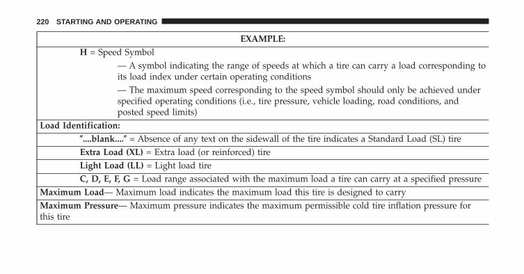
EXAMPLE:H = Speed Symbol
— A symbol indicating the range of speeds at which a tire can carry a load corresponding toits load index under certain operating conditions— The maximum speed corresponding to the speed symbol should only be achieved underspecified operating conditions (i.e., tire pressure, vehicle loading, road conditions, andposted speed limits)
Load Identification:�....blank....� = Absence of any text on the sidewall of the tire indicates a Standard Load (SL) tireExtra Load (XL) = Extra load (or reinforced) tireLight Load (LL) = Light load tireC, D, E, F, G = Load range associated with the maximum load a tire can carry at a specified pressure
Maximum Load— Maximum load indicates the maximum load this tire is designed to carryMaximum Pressure— Maximum pressure indicates the maximum permissible cold tire inflation pressure forthis tire
220 STARTING AND OPERATING
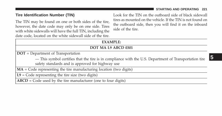
Tire Identification Number (TIN)
The TIN may be found on one or both sides of the tire,however, the date code may only be on one side. Tireswith white sidewalls will have the full TIN, including thedate code, located on the white sidewall side of the tire.
Look for the TIN on the outboard side of black sidewalltires as mounted on the vehicle. If the TIN is not found onthe outboard side, then you will find it on the inboardside of the tire.
EXAMPLE:DOT MA L9 ABCD 0301
DOT = Department of Transportation— This symbol certifies that the tire is in compliance with the U.S. Department of Transportation tiresafety standards and is approved for highway use
MA = Code representing the tire manufacturing location (two digits)L9 = Code representing the tire size (two digits)ABCD = Code used by the tire manufacturer (one to four digits)
5
STARTING AND OPERATING 221
EXAMPLE:DOT MA L9 ABCD 0301
03 = Number representing the week in which the tire was manufactured (two digits)— 03 means the 3rd week
01 = Number representing the year in which the tire was manufactured (two digits)— 01 means the year 2001— Prior to July 2000, tire manufacturers were only required to have one number to represent theyear in which the tire was manufactured. Example: 031 could represent the 3rd week of 1981 or 1991
Tire Terminology And Definitions
Term DefinitionB-Pillar The vehicle B-Pillar is the structural member of the body located
behind the front door.
222 STARTING AND OPERATING
Term DefinitionCold Tire Inflation Pressure Cold tire inflation pressure is defined as the tire pressure after
the vehicle has not been driven for at least 3 hours, or driven lessthan 1 mile (1.6 km) after sitting for a three hour period. Inflationpressure is measured in units of PSI (pounds per square inch) orkPa (kilopascals).
Maximum Inflation Pressure The maximum inflation pressure is the maximum permissiblecold tire inflation pressure for this tire. The maximum inflationpressure is molded into the sidewall.
Recommended Cold Tire InflationPressure
Vehicle manufacturer’s recommended cold tire inflation pressureas shown on the tire placard.
Tire Placard A paper label permanently attached to the vehicle describing thevehicle’s loading capacity, the original equipment tire sizes andthe recommended cold tire inflation pressures.
5
STARTING AND OPERATING 223
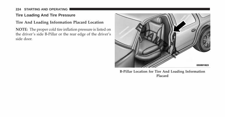
Tire Loading And Tire Pressure
Tire And Loading Information Placard Location
NOTE: The proper cold tire inflation pressure is listed onthe driver’s side B-Pillar or the rear edge of the driver’sside door.
B-Pillar Location for Tire And Loading InformationPlacard
224 STARTING AND OPERATING
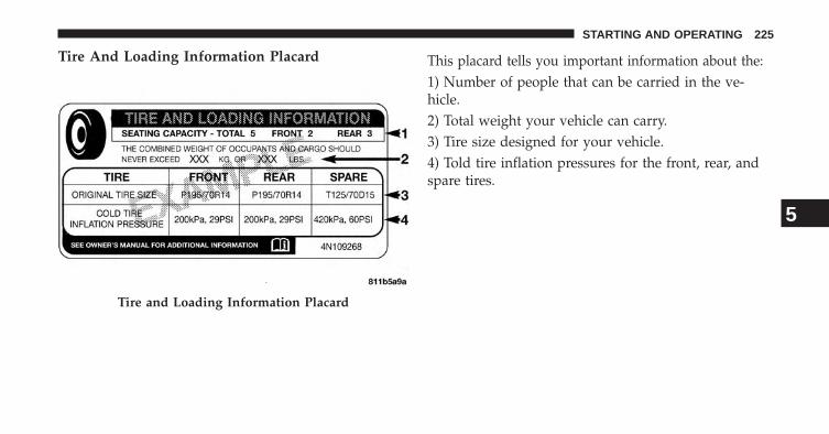
Tire And Loading Information Placard This placard tells you important information about the:1) Number of people that can be carried in the ve-hicle.2) Total weight your vehicle can carry.3) Tire size designed for your vehicle.4) Told tire inflation pressures for the front, rear, andspare tires.
Tire and Loading Information Placard
5
STARTING AND OPERATING 225

Loading
The vehicle maximum load on the tire must not exceedthe load carrying capacity of the tire on your vehicle. Youwill not exceed the tire’s load carrying capacity if youadhere to the loading conditions, tire size, and cold tireinflation pressures specified on the Tire and LoadingInformation placard and in the “Vehicle Loading” sectionof this manual.
NOTE: Under a maximum loaded vehicle condition,gross axle weight ratings (GAWRs) for the front and rearaxles must not be exceeded. For further information onGAWRs, vehicle loading, and trailer towing, refer to“Vehicle Loading” in this section.
To determine the maximum loading conditions of yourvehicle, locate the statement “The combined weight ofoccupants and cargo should never exceed XXX lbs orXXX kg” on the Tire and Loading Information placard.
The combined weight of occupants, cargo/luggage andtrailer tongue weight (if applicable) should never exceedthe weight referenced here.
Steps For Determining Correct Load Limit
1. Locate the statement “The combined weight of occu-pants and cargo should never exceed XXX lbs orXXX kg” on your vehicle’s placard.
2. Determine the combined weight of the driver andpassengers that will be riding in your vehicle.
3. Subtract the combined weight of the driver and pas-sengers from XXX lbs or XXX kg.
226 STARTING AND OPERATING
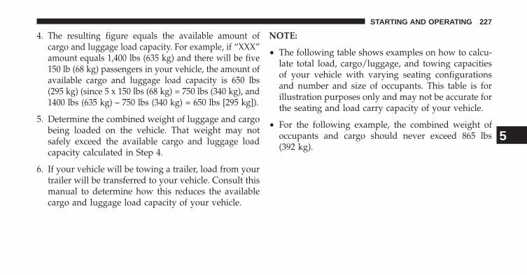
4. The resulting figure equals the available amount ofcargo and luggage load capacity. For example, if “XXX”amount equals 1,400 lbs (635 kg) and there will be five150 lb (68 kg) passengers in your vehicle, the amount ofavailable cargo and luggage load capacity is 650 lbs(295 kg) (since 5 x 150 lbs (68 kg) = 750 lbs (340 kg), and1400 lbs (635 kg) – 750 lbs (340 kg) = 650 lbs [295 kg]).
5. Determine the combined weight of luggage and cargobeing loaded on the vehicle. That weight may notsafely exceed the available cargo and luggage loadcapacity calculated in Step 4.
6. If your vehicle will be towing a trailer, load from yourtrailer will be transferred to your vehicle. Consult thismanual to determine how this reduces the availablecargo and luggage load capacity of your vehicle.
NOTE:
• The following table shows examples on how to calcu-late total load, cargo/luggage, and towing capacitiesof your vehicle with varying seating configurationsand number and size of occupants. This table is forillustration purposes only and may not be accurate forthe seating and load carry capacity of your vehicle.
• For the following example, the combined weight ofoccupants and cargo should never exceed 865 lbs(392 kg).
5
STARTING AND OPERATING 227
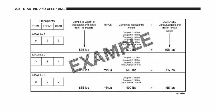
228 STARTING AND OPERATING
WARNING!
Overloading of your tires is dangerous. Overloadingcan cause tire failure, affect vehicle handling, andincrease your stopping distance. Use tires of therecommended load capacity for your vehicle. Neveroverload them.
TIRES — GENERAL INFORMATION
Tire Pressure
Proper tire inflation pressure is essential to the safe andsatisfactory operation of your vehicle. Three primaryareas are affected by improper tire pressure:
Safety
WARNING!
• Improperly inflated tires are dangerous and cancause collisions.
• Under-inflation increases tire flexing and can re-sult in over-heating and tire failure.
• Over-inflation reduces a tire’s ability to cushionshock. Objects on the road and chuckholes cancause damage that result in tire failure.
• Over-inflated or under-inflated tires can affect ve-hicle handling and can fail suddenly, resulting inloss of vehicle control.
• Unequal tire pressures can cause steering prob-lems. You could lose control of your vehicle.
(Continued)
5
STARTING AND OPERATING 229
WARNING! (Continued)• Unequal tire pressures from one side of the vehicle
to the other can cause the vehicle to drift to theright or left.
• Always drive with each tire inflated to the recom-mended cold tire inflation pressure.
Economy
Improper inflation pressures can cause uneven wear pat-terns to develop across the tire tread. These abnormal wearpatterns will reduce tread life resulting in a need for earliertire replacement. Under-inflation also increases tire rollingresistance resulting in higher fuel consumption.
Ride Comfort And Vehicle Stability
Proper tire inflation contributes to a comfortable ride.Over-inflation produces a jarring and uncomfortableride. Both under-inflation and over-inflation affect the
stability of the vehicle and can produce a feeling ofsluggish response or over responsiveness in the steering.
NOTE:
• Unequal tire pressures from side to side may causeerratic and unpredictable steering response.
• Unequal tire pressure from side to side may cause thevehicle to drift left or right.
Tire Inflation Pressures
The proper cold tire inflation pressure is listed on thedriver’s side “B” Pillar or rear edge of the driver’s side door.
At least once a month:
• Check and adjust tire pressure with a good qualitypocket-type pressure gauge. Do not make a visual judge-ment when determining proper inflation. Tires may lookproperly inflated even when they are under-inflated.
• Inspect tires for signs of tire wear or visible damage.
230 STARTING AND OPERATING
CAUTION!
After inspecting or adjusting the tire pressure, al-ways reinstall the valve stem cap. This will preventmoisture and dirt from entering the valve stem,which could damage the valve stem.
Inflation pressures specified on the placard are always“cold tire inflation pressure”. Cold tire inflation pressureis defined as the tire pressure after the vehicle has notbeen driven for at least three hours, or driven less than 1mile (1.6 km) after a three hour period. The cold tireinflation pressure must not exceed the maximum infla-tion pressure molded into the tire sidewall.
Check tire pressures more often if subject to a wide rangeof outdoor temperatures, as tire pressures vary withtemperature changes.
Tire pressures change by approximately 1 psi (7 kPa) per12°F (7°C) of air temperature change. Keep this in mindwhen checking tire pressure inside a garage, especially inthe winter.
Example: If garage temperature = 68°F (20°C) and theoutside temperature = 32°F (0°C) then the cold tireinflation pressure should be increased by 3 psi (21 kPa),which equals 1 psi (7 kPa) for every 12°F (7°C) for thisoutside temperature condition.
Tire pressure may increase from 2 to 6 psi (13 to 40 kPa)during operation. DO NOT reduce this normal pressurebuild up or your tire pressure will be too low.
5
STARTING AND OPERATING 231
Tire Pressures For High Speed Operation
The manufacturer advocates driving at safe speeds andwithin posted speed limits. Where speed limits or condi-tions are such that the vehicle can be driven at highspeeds, maintaining correct tire inflation pressure is veryimportant. Increased tire pressure and reduced vehicleloading may be required for high-speed vehicle opera-tion. Refer to your authorized tire or original equipmentvehicle dealer for recommended safe operating speeds,loading and cold tire inflation pressures.
WARNING!
High speed driving with your vehicle under maxi-mum load is dangerous. The added strain on yourtires could cause them to fail. You could have aserious collision. Do not drive a vehicle loaded to themaximum capacity at continuous speeds above75 mph (120 km/h).
Radial Ply Tires
WARNING!
Combining radial ply tires with other types of tireson your vehicle will cause your vehicle to handlepoorly. The instability could cause a collision. Al-ways use radial ply tires in sets of four. Nevercombine them with other types of tires.
Tire Repair
If your tire becomes damaged, it may be repaired if itmeets the following criteria:
• The tire has not been driven on when flat.
• The damage is only on the tread section of your tire(sidewall damage is not repairable).
• The puncture is no greater than ¼� (6 mm).
232 STARTING AND OPERATING
Consult an authorized tire dealer for tire repairs andadditional information.
Damaged Run Flat tires, or Run Flat tires that haveexperienced a loss of pressure should be replaced imme-diately with another Run Flat tire of identical size andservice description (Load Index and Speed Code).
Tire Types
All Season Tires – If Equipped
All Season tires provide traction for all seasons (spring,summer, fall and winter). Traction levels may vary be-tween different all season tires. All season tires can beidentified by the M+S, M&S, M/S or MS designation onthe tire sidewall. Use all season tires only in sets of four;failure to do so may adversely affect the safety andhandling of your vehicle.
Summer Or Three Season Tires – If Equipped
Summer tires provide traction in both wet and dryconditions, and are not intended to be driven in snow oron ice. Summer tires will not contain the all seasondesignation or mountain/snowflake symbol on the tiresidewall. Use summer tires only in sets of four; failure todo so may adversely affect the safety and handling ofyour vehicle.
Snow Tires
Some areas of the country require the use of snow tiresduring the winter. Snow tires can be identified by amountain/snowflake symbol on the tire sidewall.
If you need snow tires, select tires equivalent in size andtype to the original equipment tires. Use snow tires onlyin sets of four; failure to do so may adversely affect thesafety and handling of your vehicle.
5
STARTING AND OPERATING 233
Snow tires generally have lower speed ratings than whatwas originally equipped with your vehicle and shouldnot be operated at sustained speeds over 75 mph(120 km/h). For speeds above 75 mph (120 km/h) refer tooriginal equipment or an authorized tire dealer forrecommended safe operating speeds, loading and coldtire inflation pressures.
While studded tires improve performance on ice, skidand traction capability on wet or dry surfaces may bepoorer than that of non-studded tires. Some states pro-hibit studded tires; therefore, local laws should bechecked before using these tire types.
Run Flat Tires – If Equipped
Run Flat tires allow you the capability to drive 50 miles(80 km) at 50 mph (80 km/h) after a rapid loss of inflationpressure. This rapid loss of inflation is referred to as theRun Flat mode. A Run Flat mode occurs when the tireinflation pressure is of/or below 14 psi (96 kPa). Once aRun Flat tire reaches the run flat mode it has limiteddriving capabilities and needs to be replaced immedi-ately. A Run Flat tire is not repairable.
It is not recommended driving a vehicle loaded at fullcapacity or to tow a trailer while a tire is in the run flatmode.
See the tire pressure monitoring section for more infor-mation.
234 STARTING AND OPERATING
Spare Tires – If Equipped
NOTE: For vehicles equipped with TIREFIT instead of aspare tire, please refer to “TIREFIT KIT” in “What To DoIn Emergencies” for further information.
CAUTION!
Because of the reduced ground clearance, do not takeyour vehicle through an automatic car wash with acompact, full size or limited-use temporary spareinstalled. Damage to the vehicle may result.
Spare Tire Matching Original Equipped Tire AndWheel – If Equipped
Your vehicle may be equipped with a spare tire andwheel equivalent in look and function to the originalequipment tire and wheel found on the front or rear axleof your vehicle. This spare tire may be used in the tire
rotation for your vehicle. If your vehicle has this optionrefer to an authorized tire dealer for the recommendedtire rotation pattern.
Compact Spare Tire – If Equipped
The compact spare is for temporary emergency use only.You can identify if your vehicle is equipped with acompact spare by looking at the spare tire description onthe Tire and Loading Information Placard located on thedriver’s side door opening or on the sidewall of the tire.Compact spare tire descriptions begin with the letter “T”or “S” preceding the size designation. Example: T145/80D18 103M.
T, S = Temporary Spare Tire
Since this tire has limited tread life the original equip-ment tire should be repaired (or replaced) and reinstalledon your vehicle at the first opportunity.
5
STARTING AND OPERATING 235
Do not install a wheel cover or attempt to mount aconventional tire on the compact spare wheel, since thewheel is designed specifically for the compact spare tire.Do not install more than one compact spare tire andwheel on the vehicle at any given time.
WARNING!
Compact spares are for temporary emergency useonly. With these spares, do not drive more than50 mph (80 km/h). Temporary use spares have limitedtread life. When the tread is worn to the tread wearindicators, the temporary use spare tire needs to bereplaced. Be sure to follow the warnings, whichapply to your spare. Failure to do so could result inspare tire failure and loss of vehicle control.
Full Size Spare – If Equipped
The full size spare is for temporary emergency use only. Thistire may look like the originally equipped tire on the front orrear axle of your vehicle, but it is not. This spare tire mayhave limited tread life. When the tread is worn to the treadwear indicators, the temporary use full size spare tire needsto be replaced. Since it is not the same as your originalequipment tire, replace (or repair) the original equipmenttire and reinstall on the vehicle at the first opportunity.
Limited-Use Spare – If Equipped
The limited-use spare tire is for temporary emergencyuse only. This tire is identified by a label located on thelimited-use spare wheel. This label contains the drivinglimitations for this spare. This tire may look like theoriginal equipped tire on the front or rear axle of yourvehicle, but it is not. Installation of this limited-use sparetire affects vehicle handling. Since it is not the same asyour original equipment tire, replace (or repair) the
236 STARTING AND OPERATING
original equipment tire and reinstall on the vehicle at thefirst opportunity.
WARNING!
Limited-use spares are for emergency use only. In-stallation of this limited-use spare tire affects vehiclehandling. With this tire, do not drive more than thespeed listed on the limit-use spare wheel. Keepinflated to the cold tire inflation pressures listed onyour Tire and Loading Information Placard locatedon the driver’s side B-Pillar or the rear edge of thedriver’s side door. Replace (or repair) the originalequipment tire at the first opportunity and reinstall iton your vehicle. Failure to do so could result in lossof vehicle control.
Tire Spinning
When stuck in mud, sand, snow, or ice conditions, do notspin your vehicle’s wheels above 30 mph (48 km/h) orfor longer than 30 seconds continuously without stop-ping.
Refer to “Freeing A Stuck Vehicle” in “What To Do InEmergencies” for further information.
WARNING!
Fast spinning tires can be dangerous. Forces gener-ated by excessive wheel speeds may cause tire dam-age or failure. A tire could explode and injure some-one. Do not spin your vehicle’s wheels faster than30 mph (48 km/h) for more than 30 seconds continu-ously when you are stuck, and do not let anyone neara spinning wheel, no matter what the speed.
5
STARTING AND OPERATING 237
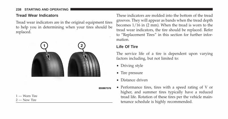
Tread Wear Indicators
Tread wear indicators are in the original equipment tiresto help you in determining when your tires should bereplaced.
These indicators are molded into the bottom of the treadgrooves. They will appear as bands when the tread depthbecomes 1/16 in (2 mm). When the tread is worn to thetread wear indicators, the tire should be replaced. Referto “Replacement Tires” in this section for further infor-mation.
Life Of Tire
The service life of a tire is dependent upon varyingfactors including, but not limited to:
• Driving style
• Tire pressure
• Distance driven
• Performance tires, tires with a speed rating of V orhigher, and summer tires typically have a reducedtread life. Rotation of these tires per the vehicle main-tenance schedule is highly recommended.
1 — Worn Tire2 — New Tire
238 STARTING AND OPERATING
WARNING!
Tires and the spare tire should be replaced after sixyears, regardless of the remaining tread. Failure tofollow this warning can result in sudden tire failure.You could lose control and have a collision resultingin serious injury or death.
Keep dismounted tires in a cool, dry place with as littleexposure to light as possible. Protect tires from contactwith oil, grease, and gasoline.
Replacement Tires
The tires on your new vehicle provide a balance of manycharacteristics. They should be inspected regularly forwear and correct cold tire inflation pressure. The manu-facturer strongly recommends that you use tires equiva-lent to the originals in size, quality and performancewhen replacement is needed. Refer to the paragraph on“Tread Wear Indicators.” Refer to the Tire and Loading
Information placard or the Vehicle Certification Label forthe size designation of your tire. The Load Index andSpeed Symbol for your tire will be found on the originalequipment tire sidewall. See the Tire Sizing Chart ex-ample found in the Tire Safety Information section of thismanual for more information relating to the Load Indexand Speed Symbol of a tire.
It is recommended to replace the two front tires or tworear tires as a pair. Replacing just one tire can seriouslyaffect your vehicle’s handling. If you ever replace awheel, make sure that the wheel’s specifications matchthose of the original wheels.
It is recommended you contact your authorized tire ororiginal equipment dealer with any questions you mayhave on tire specifications or capability. Failure to useequivalent replacement tires may adversely affect thesafety, handling, and ride of your vehicle.
5
STARTING AND OPERATING 239
WARNING!
• Do not use a tire, wheel size or rating other thanthat specified for your vehicle. Some combinationsof unapproved tires and wheels may change sus-pension dimensions and performance characteris-tics, resulting in changes to steering, handling, andbraking of your vehicle. This can cause unpredict-able handling and stress to steering and suspen-sion components. You could lose control and havea collision resulting in serious injury or death. Useonly the tire and wheel sizes with load ratingsapproved for your vehicle.
• Never use a tire with a smaller load index orcapacity, other than what was originally equippedon your vehicle. Using a tire with a smaller loadindex could result in tire overloading and failure.You could lose control and have a collision.
(Continued)
WARNING! (Continued)• Failure to equip your vehicle with tires having
adequate speed capability can result in sudden tirefailure and loss of vehicle control.
CAUTION!
Replacing original tires with tires of a different size mayresult in false speedometer and odometer readings.
TIRE CHAINS (TRACTION DEVICES)
Due to limited clearance, tire chains or traction devicesare not recommended.
CAUTION!
Damage to the vehicle may result if tire chains areused.
240 STARTING AND OPERATING
TIRE ROTATION RECOMMENDATIONS
Tires on the front and rear axles of vehicles operate atdifferent loads and perform different steering, driving,and braking functions. For these reasons, they wear atunequal rates.
These effects can be reduced by timely rotation of tires.The benefits of rotation are especially worthwhile withaggressive tread designs such as those on all season typetires. Rotation will increase tread life, help to maintainmud, snow, and wet traction levels, and contribute to asmooth, quiet ride.
Refer to the “Maintenance Schedule” for the propermaintenance interval. Remember, more frequent rotationis permissible if desired. Also, correct for anything caus-ing rapid or unusual wear prior to performing the tirerotation.
NOTE: Each wheel on your vehicle contains a tire pres-sure sensor. The Tire Pressure Monitor System (TPMS)learns the location of each sensor though system pro-gramming. Although not required, the manufacturerrecommends reprogramming the TPMS after rotating thetires so that the system can relearn each sensor’s location.See your authorized dealer for system reprogramming.
5
STARTING AND OPERATING 241
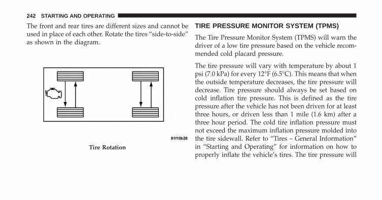
The front and rear tires are different sizes and cannot beused in place of each other. Rotate the tires “side-to-side”as shown in the diagram.
TIRE PRESSURE MONITOR SYSTEM (TPMS)
The Tire Pressure Monitor System (TPMS) will warn thedriver of a low tire pressure based on the vehicle recom-mended cold placard pressure.
The tire pressure will vary with temperature by about 1psi (7.0 kPa) for every 12°F (6.5°C). This means that whenthe outside temperature decreases, the tire pressure willdecrease. Tire pressure should always be set based oncold inflation tire pressure. This is defined as the tirepressure after the vehicle has not been driven for at leastthree hours, or driven less than 1 mile (1.6 km) after athree hour period. The cold tire inflation pressure mustnot exceed the maximum inflation pressure molded intothe tire sidewall. Refer to “Tires – General Information”in “Starting and Operating” for information on how toproperly inflate the vehicle’s tires. The tire pressure will
Tire Rotation
242 STARTING AND OPERATING
also increase as the vehicle is driven - this is normal andthere should be no adjustment for this increased pres-sure.
The TPMS will warn the driver of a low tire pressure ifthe tire pressure falls below the low-pressure warninglimit for any reason, including low temperature effectsand natural pressure loss through the tire.
The TPMS will continue to warn the driver of low tirepressure as long as the condition exists, and will not turnoff until the tire pressure is at or above the recommendedcold placard pressure. Once the low tire pressure warn-ing (Tire Pressure Monitoring [TPM] Telltale Light) illu-minates, you must increase the tire pressure to therecommended cold placard pressure in order for the TPMTelltale Light to turn off. The system will automaticallyupdate and the TPM Telltale Light will turn off once thesystem receives the updated tire pressures. The vehicle
may need to be driven for up to 20 minutes above 15 mph(24 km/h) in order for the TPMS to receive this informa-tion.
For example, your vehicle may have a recommendedcold (parked for more than three hours) placard pressureof 30 psi (207 kPa). If the ambient temperature is 68°F(20°C) and the measured tire pressure is 27 psi (186 kPa),a temperature drop to 20°F (-7°C) will decrease the tirepressure to approximately 23 psi (158 kPa). This tirepressure is sufficiently low enough to urn ON the TPMTelltale Light. Driving the vehicle may cause the tirepressure to rise to approximately 27 psi (186 kPa), but theTPM Telltale Light will still be ON. In this situation, theTPM Telltale Light will turn OFF only after the tires areinflated to the vehicle’s recommended cold placard pres-sure value.
5
STARTING AND OPERATING 243
CAUTION!
• The TPMS has been optimized for the originalequipment tires and wheels. TPMS pressures andwarning have been established for the tire sizeequipped on your vehicle. Undesirable system op-eration or sensor damage may result when usingreplacement equipment that is not of the same size,type, and/or style. Aftermarket wheels can causesensor damage. Do not use aftermarket tire sealantsor balance beads if your vehicle is equipped with aTPMS, as damage to the sensors may result.
• After inspecting or adjusting the tire pressure,always reinstall the valve stem cap. This willprevent moisture and dirt from entering the valvestem, which could damage the TPM sensor.
NOTE:
• The TPMS is not intended to replace normal tire careand maintenance or to provide warning of a tire failureor condition.
• The TPMS should not be used as a tire pressure gaugewhile adjusting your tire pressure.
• Driving on a significantly under-inflated tire causesthe tire to overheat and can lead to tire failure.Under-inflation also reduces fuel efficiency and tiretread life, and may affect the vehicle’s handling andstopping ability.
• The TPMS is not a substitute for proper tire mainte-nance, and it is the driver’s responsibility to maintaincorrect tire pressure using an accurate tire pressuregauge, even if under-inflation has not reached the levelto trigger illumination of the TPM Telltale Light.
244 STARTING AND OPERATING
• Seasonal temperature changes will affect tire pressure,and the TPMS will monitor the actual tire pressure inthe tire.
Premium System
The Tire Pressure Monitor System (TPMS) uses wirelesstechnology with wheel rim mounted electronic sensors tomonitor tire pressure levels. Sensors mounted to eachwheel as part of the valve stem transmit tire pressurereadings to the receiver module. It is particularly impor-tant for you to check the tire pressure in all of the tires onyour vehicle monthly and to maintain the proper pres-sure. The TPMS consists of the following components:• Receiver module, • Four TPM sensors, • Various TPMSmessages, which display in the Electronic Vehicle Infor-mation Center (EVIC), and • TPM Telltale Light
Tire Pressure Monitoring Low Pressure Warnings
The TPM Telltale Light will illuminate in the instru-ment cluster and a chime will sound when tirepressure is low in one or more of the four active
road tires. In addition, the EVIC will display a �LOW TIRE�message and a graphic showing the pressure values of eachtire with the low tire pressure values flashing or changingcolor. An �Inflate to XX� message will also be displayed.
Should this occur, you should stop as soon as possibleand inflate the tires with a low pressure condition (thosein a different color in the EVIC graphic) to the vehicle’srecommended cold placard pressure inflation value asshown in the �Inflate to XX� message. Once the systemreceives the updated tire pressures, the system willautomatically update, the graphic display in the EVICwill change color back to the original color, and the TPMTelltale Light will turn off. The vehicle may need to bedriven for up to 20 minutes above 15 mph (24 km/h) inorder for the TPMS to receive this information.
5
STARTING AND OPERATING 245
Service TPMS Warning
If a system fault is detected, the TPM Telltale Light willflash on and off for 75 seconds and then remain on solid.The system fault will also sound a chime. In addition, theEVIC will display a �SERVICE TPM SYSTEM� message fora minimum of five seconds and then display dashes (- -)in place of the pressure value to indicate which sensor isnot being received.
If the ignition switch is cycled, this sequence will repeat,providing the system fault still exists. If the system faultno longer exists, the TPM Telltale Light will no longerflash, and the �SERVICE TPM SYSTEM� message will nolonger display, and a pressure value will display in placeof the dashes. A system fault can occur due to any of thefollowing:
1. Signal interference due to electronic devices or drivingnext to facilities emitting the same radio frequencies asthe TPM sensors.
2. Installing aftermarket window tinting that containsmaterials that may block radio wave signals.
3. Accumulation of snow or ice around the wheels orwheel housings.
4. Using tire chains on the vehicle.
5. Using wheels/tires not equipped with TPM sensors.
The EVIC will also display a �SERVICE TPM SYSTEM�message for a minimum of five seconds when a systemfault related to an incorrect sensor location fault isdetected. In this case, the �SERVICE TPM SYSTEM�message is then followed with a graphic display withpressure values still shown. This indicates that the pres-sure values are still being received from the TPM sensorsbut they may not be located in the correct vehicleposition. The system still needs to be serviced as long asthe �SERVICE TPM SYSTEM� message is displayed.
246 STARTING AND OPERATING
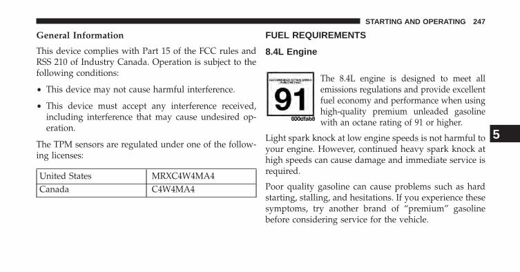
General Information
This device complies with Part 15 of the FCC rules andRSS 210 of Industry Canada. Operation is subject to thefollowing conditions:
• This device may not cause harmful interference.
• This device must accept any interference received,including interference that may cause undesired op-eration.
The TPM sensors are regulated under one of the follow-ing licenses:
United States MRXC4W4MA4Canada C4W4MA4
FUEL REQUIREMENTS
8.4L Engine
The 8.4L engine is designed to meet allemissions regulations and provide excellentfuel economy and performance when usinghigh-quality premium unleaded gasolinewith an octane rating of 91 or higher.
Light spark knock at low engine speeds is not harmful toyour engine. However, continued heavy spark knock athigh speeds can cause damage and immediate service isrequired.
Poor quality gasoline can cause problems such as hardstarting, stalling, and hesitations. If you experience thesesymptoms, try another brand of “premium” gasolinebefore considering service for the vehicle.
5
STARTING AND OPERATING 247
Over 40 automobile manufacturers around the worldhave issued and endorsed consistent gasoline specifica-tions (the World Wide Fuel Charter, WWFC) whichdefine fuel properties necessary to deliver enhancedemissions, engine performance, and durability for yourvehicle. The manufacturer recommends the use of gaso-lines that meet the WWFC specifications if they areavailable.
Reformulated Gasoline
Many areas of the country require the use of cleanerburning gasoline referred to as “Reformulated Gasoline.”Reformulated gasolines contain oxygenates and are spe-cifically blended to reduce vehicle emissions and im-prove air quality.
The manufacturer supports the use of reformulated gaso-lines. Properly blended reformulated gasolines will pro-vide excellent performance and durability of engine andfuel system components.
Gasoline/Oxygenate Blends
Some fuel suppliers blend unleaded gasoline with oxy-genates such as Ethanol. Fuels blended with oxygenatesmay be used in your vehicle.
CAUTION!
DO NOT use gasoline containing Methanol or gaso-line containing more than 10% Ethanol. Use of theseblends may result in starting and drivability prob-lems, damage critical fuel system components, causeemissions to exceed the applicable standard, and/orcause the “Malfunction Indicator Light” to illumi-nate. Pump labels should clearly communicate if afuel contains greater than 10% Ethanol.
Problems that result from using gasoline containingMethanol or gasoline containing more than 10% Ethanolare not the responsibility of the manufacturer and maynot be covered under New Vehicle Limited Warranty.
248 STARTING AND OPERATING
E-85 Usage In Non-Flex Fuel Vehicles
Non-Flex Fuel Vehicle (FFV) is compatible with gasolinecontaining 10% ethanol (E10). Gasoline with higher etha-nol content may void the New Vehicle Limited Warranty.
If a Non-FFV vehicle is inadvertently fueled with E-85fuel, the engine will have some or all of these symptoms:
• Operate in a lean mode.
• OBD II “Malfunction Indicator Light” on.
• Poor engine performance.
• Poor cold start and cold drivability.
• Increased risk for fuel system component corrosion.
To fix a Non-FFV vehicle inadvertently fueled once withE-85 perform the following:
• Drain the fuel tank (see your authorized dealer.)
• Change the engine oil and oil filter.
• Disconnect and reconnect the battery to reset theengine controller memory.
More extensive repairs will be required for prolongedexposure to E-85 fuel.
MMT In Gasoline
MMT (Methylcyclopentadienyl Manganese Tricarbonyl)is a manganese-containing metallic additive that isblended into some gasoline to increase octane. Gasolineblended with MMT provides no performance advantagebeyond gasoline of the same octane number withoutMMT. Gasoline blended with MMT reduces spark pluglife and reduces emissions system performance in somevehicles. The manufacturer recommends that gasolinewithout MMT be used in your vehicle. The MMT contentof gasoline may not be indicated on the gasoline pump,therefore, you should ask your gasoline retailer whetherthe gasoline contains MMT. MMT is prohibited in Federaland California reformulated gasoline.
5
STARTING AND OPERATING 249
Materials Added To Fuel
All gasoline sold in the United States is required tocontain effective detergent additives. Use of additionaldetergents or other additives is not needed under normalconditions and they would result in additional cost.Therefore, you should not have to add anything to thefuel.
Fuel System Cautions
CAUTION!
Follow these guidelines to maintain your vehicle’sperformance:• The use of leaded gas is prohibited by Federal law.
Using leaded gasoline can impair engine perfor-mance and damage the emissions control system.
(Continued)
CAUTION! (Continued)• An out-of-tune engine or certain fuel or ignition
malfunctions can cause the catalytic converter tooverheat. If you notice a pungent burning odor orsome light smoke, your engine may be out of tuneor malfunctioning and may require immediate ser-vice. Contact your authorized dealer for serviceassistance.
• The use of fuel additives, which are now beingsold as octane enhancers, is not recommended.Most of these products contain high concentrationsof methanol. Fuel system damage or vehicle perfor-mance problems resulting from the use of suchfuels or additives is not the responsibility of themanufacturer.
NOTE: Intentional tampering with the emissions controlsystem can result in civil penalties being assessed againstyou.
250 STARTING AND OPERATING
Carbon Monoxide Warnings
WARNING!
Carbon monoxide (CO) in exhaust gases is deadly.Follow the precautions below to prevent carbonmonoxide poisoning:• Do not inhale exhaust gases. They contain carbon
monoxide, a colorless and odorless gas, which cankill. Never run the engine in a closed area, such asa garage, and never sit in a parked vehicle with theengine running for an extended period. If thevehicle is stopped in an open area with the enginerunning for more than a short period, adjust theventilation system to force fresh, outside air intothe vehicle.
(Continued)
WARNING! (Continued)• Guard against carbon monoxide with proper main-
tenance. Have the exhaust system inspected everytime the vehicle is raised. Have any abnormalconditions repaired promptly. Until repaired, drivewith all side windows fully open.
• Keep the trunk closed when driving your vehicle toprevent carbon monoxide and other poisonous ex-haust gases from entering the vehicle.
ADDING FUEL
1. Press the fuel filler door release switch (located in thedriver’s door map pocket).
2. Open the fuel filler door.
3. There is no fuel filler cap. A flapper door inside thepipe seals the system.
5
STARTING AND OPERATING 251
4. Insert the fuel nozzle fully into the filler pipe – thenozzle opens and holds the flapper door while refuel-ing.
NOTE: Only the correct size nozzle opens the latchesallowing the flapper door to open.
5. Fill the vehicle with fuel – when the fuel nozzle“clicks” or shuts off the fuel tank is full.
6. Remove the fuel nozzle and close the fuel door.
NOTE: A funnel is provided (located in the trunk in thespare tire area) to open the flapper door to allow foremergency refueling with a gas can.
CAUTION!
To avoid fuel spillage and overfilling, do not “topoff” the fuel tank after filling.
WARNING!
• Never have any smoking materials lit in or near thevehicle when the fuel door is open or the tank isbeing filled.
• Never add fuel when the engine is running. This isin violation of most state and federal fire regula-tions and may cause the “Malfunction IndicatorLight” to turn on.
• A fire may result if fuel is pumped into a portablecontainer that is inside of a vehicle. You could beburned. Always place fuel containers on theground while filling.
252 STARTING AND OPERATING
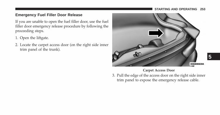
Emergency Fuel Filler Door Release
If you are unable to open the fuel filler door, use the fuelfiller door emergency release procedure by following theproceeding steps.
1. Open the liftgate.
2. Locate the carpet access door (on the right side innertrim panel of the trunk).
3. Pull the edge of the access door on the right side innertrim panel to expose the emergency release cable.
Carpet Access Door
5
STARTING AND OPERATING 253
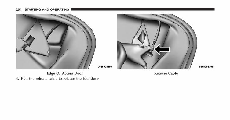
4. Pull the release cable to release the fuel door.Edge Of Access Door Release Cable
254 STARTING AND OPERATING
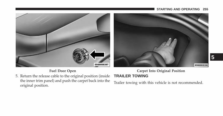
5. Return the release cable to the original position (insidethe inner trim panel) and push the carpet back into theoriginal position.
TRAILER TOWING
Trailer towing with this vehicle is not recommended.
Fuel Door Open Carpet Into Original Position
5
STARTING AND OPERATING 255
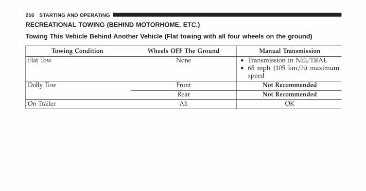
RECREATIONAL TOWING (BEHIND MOTORHOME, ETC.)
Towing This Vehicle Behind Another Vehicle (Flat towing with all four wheels on the ground)
Towing Condition Wheels OFF The Ground Manual TransmissionFlat Tow None • Transmission in NEUTRAL
• 65 mph (105 km/h) maximumspeed
Dolly Tow Front Not RecommendedRear Not Recommended
On Trailer All OK
256 STARTING AND OPERATING
GROUND CLEARANCE
The front and rear fascias and side sills ride low andground clearance is limited.
CAUTION!
Damage to the front and rear fascias and side sills canoccur if you disregard the low ground clearance inthese areas of your vehicle. Pay close attention whenparking to avoid running into parking curbs. Exer-cise caution when entering or exiting steep drive-ways, or when pulling off the road onto soft shoul-ders.
5
STARTING AND OPERATING 257

WHAT TO DO IN EMERGENCIES
CONTENTS� HAZARD WARNING FLASHER . . . . . . . . . . .260
� IF YOUR ENGINE OVERHEATS . . . . . . . . . . . .260
� TIREFIT KIT . . . . . . . . . . . . . . . . . . . . . . . . . .261
▫ TIREFIT Storage . . . . . . . . . . . . . . . . . . . . . .262
▫ TIREFIT Kit Components And Operation . . . . .262
▫ TIREFIT Usage Precautions. . . . . . . . . . . . . . .264
▫ Sealing A Tire With TIREFIT . . . . . . . . . . . . . .266
� JUMP-STARTING PROCEDURES . . . . . . . . . . .272
� FREEING A STUCK VEHICLE . . . . . . . . . . . . .275
� TOWING A DISABLED VEHICLE . . . . . . . . . . .276 6
HAZARD WARNING FLASHER
The Hazard Warning flasher switch is located in thecenter of the instrument panel above the climate controls.
Press the switch to turn on the Hazard Warningflasher. When the switch is activated, all direc-
tional turn signals will flash on and off to warn oncomingtraffic of an emergency. Press the switch a second time toturn off the Hazard Warning flasher.
This is an emergency warning system and it should notbe used when the vehicle is in motion. Use it when yourvehicle is disabled and it is creating a safety hazard forother motorists.
When you must leave the vehicle to seek assistance, theHazard Warning flasher will continue to operate eventhough the ignition is placed in the OFF position.
NOTE: With extended use the Hazard Warning flashermay wear down your battery.
IF YOUR ENGINE OVERHEATS
In any of the following situations, you can reduce thepotential for overheating by taking the appropriate action.
• On the highways — Slow down and use the highestgear possible.
• In city traffic — While stopped, put the transmissionin NEUTRAL, but do not increase engine idle speed.
260 WHAT TO DO IN EMERGENCIES
• In city traffic — While moving, shift into the highestgear possible to reduce engine RPM.
NOTE: There are steps that you can take to slow downan impending overheat condition:
• If your air conditioner (A/C) is on, turn it off. The A/Csystem adds heat to the engine cooling system andturning the A/C off can help remove this heat.
• You can also turn the temperature control to maximumheat, the mode control to floor and the blower controlto high. This allows the heater core to act as asupplement to the radiator and aids in removing heatfrom the engine cooling system.
WARNING!
You or others can be badly burned by hot enginecoolant (antifreeze) or steam from your radiator. Ifyou see or hear steam coming from under the hood,do not open the hood until the radiator has had timeto cool. Never try to open a cooling system pressurecap when the radiator or coolant bottle is hot.
TIREFIT KIT
Small punctures up to ¼” (6 mm) in the tire tread can besealed with TIREFIT. Foreign objects (e.g., screws or nails)should not be removed from the tire. TIREFIT can be used inoutside temperatures down to approximately -4°F (-20°C).
This kit will provide a temporary tire seal, allowing youto drive your vehicle up to 100 miles (160 km) with amaximum speed of 55 mph (88 km/hr).
6
WHAT TO DO IN EMERGENCIES 261
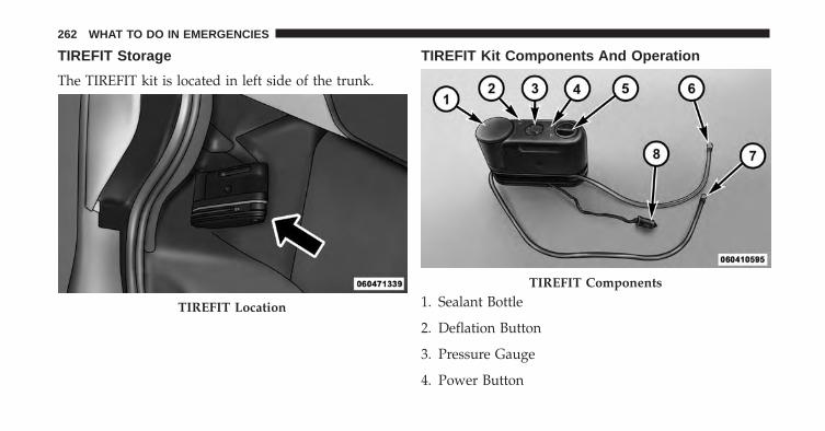
TIREFIT Storage
The TIREFIT kit is located in left side of the trunk.
TIREFIT Kit Components And Operation
1. Sealant Bottle
2. Deflation Button
3. Pressure Gauge
4. Power Button
TIREFIT Location
TIREFIT Components
262 WHAT TO DO IN EMERGENCIES
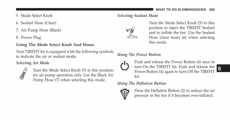
5. Mode Select Knob
6. Sealant Hose (Clear)
7. Air Pump Hose (Black)
8. Power Plug
Using The Mode Select Knob And Hoses
Your TIREFIT kit is equipped with the following symbolsto indicate the air or sealant mode.
Selecting Air Mode
Turn the Mode Select Knob (5) to this positionfor air pump operation only. Use the Black AirPump Hose (7) when selecting this mode.
Selecting Sealant Mode
Turn the Mode Select Knob (5) to thisposition to inject the TIREFIT Sealantand to inflate the tire. Use the SealantHose (clear hose) (6) when selectingthis mode.
Using The Power Button
Push and release the Power Button (4) once toturn On the TIREFIT kit. Push and release thePower Button (4) again to turn Off the TIREFITkit.
Using The Deflation Button
Press the Deflation Button (2) to reduce the airpressure in the tire if it becomes over-inflated.
6
WHAT TO DO IN EMERGENCIES 263
TIREFIT Usage Precautions
• Using the TIREFIT sealant may cause the Tire PressureMonitoring System (TPMS) to become inoperable. It isrecommended that you take your vehicle to an autho-rized dealer to have the sensor function checked.
• Replace the TIREFIT Sealant Bottle (1) and SealantHose (6) prior to the expiration date (printed on thebottle label) to assure optimum operation of the sys-tem. Refer to “Sealing a Tire with TIREFIT” section (F)“Sealant Bottle and Hose Replacement.”
• The Sealant Bottle (1) and Sealant Hose (6) are a onetire application use. After each use, always replacethese components immediately at an authorizeddealer.
• When the TIREFIT sealant is in a liquid form, cleanwater, and a damp cloth will remove the material from
the vehicle or tire and wheel components. Once thesealant dries, it can easily be peeled off and properlydiscarded.
• For optimum performance, make sure the valve stemon the wheel is free of debris before connecting theTIREFIT kit.
• You can use the TIREFIT air pump to inflate bicycletires. The kit also comes with two needles, located inthe Accessory Storage Compartment (on the bottom ofthe air pump) for inflating sport balls, rafts, or similarinflatable items. However, use only the Air Pump Hose(7) and make sure the Mode Select Knob (5) is in theAir Mode when inflating such items to avoid injectingsealant into them. The TIREFIT Sealant is only in-tended to seal punctures less than ¼ in (6 mm)diameter in the tread of your vehicle.
• Do not lift or carry the TIREFIT kit by the hoses.
264 WHAT TO DO IN EMERGENCIES
WARNING!
• Do not attempt to seal a tire on the side of thevehicle closest to traffic. Pull far enough off theroad to avoid the danger of being hit when usingthe TIREFIT kit.
• Do not use TIREFIT or drive the vehicle under thefollowing circumstances:– If the puncture in the tire tread is approximately
1/4 in. (6 mm) or larger.– If the tire has any sidewall damage.– If the tire has any damage from driving with
extremely low tire pressure.– If the tire has any damage from driving on a flat
tire.– If the wheel has any damage.– If you are unsure of the condition of the tire or
the wheel.
(Continued)
WARNING! (Continued)• Keep TIREFIT away from open flames or heat
source.• A loose TIREFIT kit thrown forward in a collision
or hard stop could endanger the occupants of thevehicle. Always stow the TIREFIT kit in the placeprovided. Failure to follow these warnings canresult in injuries that are serious or fatal to you,your passengers, and others around you.
• Take care not to allow the contents of TIREFIT tocome in contact with hair, eyes, or clothing. TIRE-FIT is harmful if inhaled, swallowed, or absorbedthrough the skin. It causes skin, eye, and respira-tory irritation. Flush immediately with plenty ofwater if there is any contact with eyes or skin.Change clothing as soon as possible, if there is anycontact with clothing.
(Continued)
6
WHAT TO DO IN EMERGENCIES 265
WARNING! (Continued)• TIREFIT Sealant solution contains latex. In case of
an allergic reaction or rash, consult a physicianimmediately. Keep TIREFIT out of reach of children.If swallowed, rinse mouth immediately with plentyof water and drink plenty of water. Do not inducevomiting! Consult a physician immediately.
Sealing A Tire With TIREFIT
(A) Whenever You Stop To Use TIREFIT:
1. Pull over to a safe location and turn on the vehicle’sHazard Warning flashers.
2. Verify that the valve stem (on the wheel with thedeflated tire) is in a position that is near to the ground.This will allow the TIREFIT Hoses (6) and (7) to reachthe valve stem and keep the TIREFIT kit flat on theground. This will provide the best positioning of the kit
when injecting the sealant into the deflated tire andrunning the air pump. Move the vehicle as necessary toplace the valve stem in this position before proceeding.
3. Place the transmission in Gear and place the ignitionin the OFF position.
4. Set the parking brake.
(B) Setting Up To Use TIREFIT:
1. Turn the Mode Select Knob (5) to the Sealant Modeposition.
2. Uncoil the Sealant Hose (6) and then remove the capfrom the fitting at the end of the hose.
3. Place the TIREFIT kit flat on the ground next to thedeflated tire.
4. Remove the cap from the valve stem and then screwthe fitting at the end of the Sealant Hose (6) onto thevalve stem.
266 WHAT TO DO IN EMERGENCIES
5. Uncoil the Power Plug (8) and insert the plug into thevehicle’s 12 Volt power outlet.
NOTE: Do not remove foreign objects (e.g., screws ornails) from the tire.
(C) Injecting TIREFIT Sealant Into The Deflated Tire:
• Always start the engine before turning ON the TIRE-FIT kit.
NOTE: Manual transmission vehicles must have theparking brake engaged and the shift lever in NEUTRAL.
• After pressing the Power Button (4), the sealant (whitefluid) will flow from the Sealant Bottle (1) through theSealant Hose (6) and into the tire.
NOTE: Sealant may leak out through the puncture in thetire.
If the sealant (white fluid) does not flow within 0 – 10seconds through the Sealant Hose (6):
1. Press the Power Button (4) to turn Off the TIREFIT kit.Disconnect the Sealant Hose (6) from the valve stem.Make sure the valve stem is free of debris. Reconnectthe Sealant Hose (6) to the valve stem. Check that theMode Select Knob (5) is in the Sealant Mode positionand not Air Mode. Press the Power Button (4) to turnOn the TIREFIT kit.
2. Connect the Power Plug (8) to a different 12 Voltpower outlet in your vehicle or another vehicle, ifavailable. Make sure the engine is running beforeturning ON the TIREFIT kit.
3. The Sealant Bottle (1) may be empty due to previoususe. Call for assistance.
6
WHAT TO DO IN EMERGENCIES 267
NOTE: If the Mode Select Knob (5) is on Air Mode andthe pump is operating, air will dispense from the AirPump Hose (7) only, not the Sealant Hose (6).
If the sealant (white fluid) does flow through theSealant Hose (6):
1. Continue to operate the pump until sealant is nolonger flowing through hose (typically takes 30 - 70seconds). As the sealant flows through the SealantHose (6), the Pressure Gauge (3) can read as high as 70psi (5 Bar). The Pressure Gauge (3) will decreasequickly from approximately 70 psi (5 Bar) to the actualtire pressure when the Sealant Bottle (1) is empty.
2. The pump will start to inject air into the tire immedi-ately after the Sealant Bottle (1) is empty. Continue tooperate the pump and inflate the tire to the pressureindicated on the tire pressure label on the driver-sidelatch pillar (recommended pressure). Check the tirepressure by looking at the Pressure Gauge (3).
If the tire does not inflate to at least 26 psi (1.8 Bar)pressure within 15 minutes:
• The tire is too badly damaged. Do not attempt to drivethe vehicle further. Call for assistance.
NOTE: If the tire becomes over-inflated, press the Defla-tion Button to reduce the tire pressure to the recom-mended inflation pressure before continuing.
If the tire inflates to the recommended pressure or is atleast 26 psi (1.8 Bar) pressure within 15 minutes:
1. Press the Power Button (4) to turn off the TIREFIT kit.
2. Remove the Speed Limit sticker from the top of theSealant Bottle (1) and place the sticker on the instru-ment panel.
268 WHAT TO DO IN EMERGENCIES
3. Immediately disconnect the Sealant Hose (6) from thevalve stem, reinstall the cap on the fitting at the end ofthe hose, and place the TIREFIT kit in the vehiclestorage location. Quickly proceed to (D) “Drive Ve-hicle.”
CAUTION!
• The metal end fitting from Power Plug (8) may gethot after use, so it should be handled carefully.
• Failure to reinstall the cap on the fitting at the endof the Sealant Hose (6) can result in sealant con-tacting your skin, clothing, and the vehicle’s inte-rior. It can also result in sealant contacting internalTIREFIT kit components which may cause perma-nent damage to the kit.
(D) Drive Vehicle:
Immediately after injecting sealant and inflating the tire,drive the vehicle 5 miles (8 km) or 10 minutes to ensuredistribution of the TIREFIT Sealant within the tire. Do notexceed 55 mph (88 km/h).
WARNING!
TIREFIT is not a permanent flat tire repair. Have thetire inspected and repaired or replaced after usingTIREFIT. Do not exceed 55 mph (88 km/h) until thetire is repaired or replaced. Failure to follow thiswarning can result in injuries that are serious or fatalto you, your passengers, and others around you.
6
WHAT TO DO IN EMERGENCIES 269
(E) After Driving:
Pull over to a safe location. Refer to “Whenever You Stopto Use TIREFIT” before continuing.
1. Turn the Mode Select Knob (5) to the Air Modeposition.
2. Uncoil the power plug and insert the plug into thevehicle’s 12 Volt power outlet.
3. Uncoil the Air Pump Hose (7) (black in color) andscrew the fitting at the end of hose (7) onto the valvestem.
4. Check the pressure in the tire by reading the PressureGauge (3).
If tire pressure is less than 19 psi (1.3 Bar), the tire is toobadly damaged. Do not attempt to drive the vehiclefurther. Call for assistance.
If the tire pressure is 19 psi (1.3 Bar) or higher:
1. Press the Power Button (4) to turn on TIREFIT andinflate the tire to the pressure indicated on the tire andloading information label on the driver-side dooropening.
NOTE: If the tire becomes over-inflated, press the Defla-tion Button to reduce the tire pressure to the recom-mended inflation pressure before continuing.
2. Disconnect the TIREFIT kit from the valve stem,reinstall the cap on the valve stem and unplug from 12Volt outlet.
3. Place the TIREFIT kit in its proper storage area in thevehicle.
4. Have the tire inspected and repaired or replaced at theearliest opportunity at an authorized dealer or tireservice center.
270 WHAT TO DO IN EMERGENCIES
5. Replace the Sealant Bottle (1) and Sealant Hose (6)assembly at your authorized dealer as soon as pos-sible. Refer to “(F) Sealant Bottle and Hose Replace-ment.”
NOTE: When having the tire serviced, advise the autho-rized dealer or service center that the tire has been sealedusing the TIREFIT service kit.
(F) Sealant Bottle And Hose Replacement:
1. Uncoil the Sealant Hose (6) (clear in color).
2. Locate the round Sealant Bottle release button in therecessed area under the sealant bottle.
3. Press the Sealant Bottle release button. The SealantBottle (1) will pop up. Remove the bottle and disposeof it accordingly.
4. Clean any remaining sealant from the TIREFIT hous-ing.
5. Position the new Sealant Bottle (1) in the housing sothat the Sealant Hose (6) aligns with the hose slot inthe front of the housing. Press the bottle into thehousing. An audible click will be heard indicating thebottle is locked into place.
6. Verify that the cap is installed on the fitting at the endof the Sealant Hose (6) and return the hose to itsstorage area (located on the bottom of the air pump).
7. Return the TIREFIT kit to its storage location in thevehicle.
6
WHAT TO DO IN EMERGENCIES 271
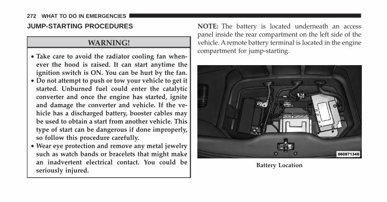
JUMP-STARTING PROCEDURES
WARNING!
• Take care to avoid the radiator cooling fan when-ever the hood is raised. It can start anytime theignition switch is ON. You can be hurt by the fan.
• Do not attempt to push or tow your vehicle to get itstarted. Unburned fuel could enter the catalyticconverter and once the engine has started, igniteand damage the converter and vehicle. If the ve-hicle has a discharged battery, booster cables maybe used to obtain a start from another vehicle. Thistype of start can be dangerous if done improperly,so follow this procedure carefully.
• Wear eye protection and remove any metal jewelrysuch as watch bands or bracelets that might makean inadvertent electrical contact. You could beseriously injured.
NOTE: The battery is located underneath an accesspanel inside the rear compartment on the left side of thevehicle. A remote battery terminal is located in the enginecompartment for jump-starting.
Battery Location
272 WHAT TO DO IN EMERGENCIES
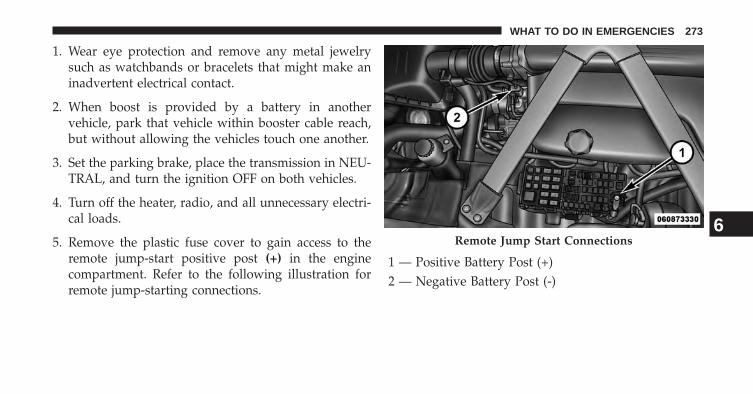
1. Wear eye protection and remove any metal jewelrysuch as watchbands or bracelets that might make aninadvertent electrical contact.
2. When boost is provided by a battery in anothervehicle, park that vehicle within booster cable reach,but without allowing the vehicles touch one another.
3. Set the parking brake, place the transmission in NEU-TRAL, and turn the ignition OFF on both vehicles.
4. Turn off the heater, radio, and all unnecessary electri-cal loads.
5. Remove the plastic fuse cover to gain access to theremote jump-start positive post (+) in the enginecompartment. Refer to the following illustration forremote jump-starting connections.
1 — Positive Battery Post (+)2 — Negative Battery Post (-)
Remote Jump Start Connections6
WHAT TO DO IN EMERGENCIES 273
CAUTION!
Failure to follow these procedures could result indamage to the charging system of the booster vehicleor the discharged vehicle.
6. Connect the positive (+) end of the jumper cable to theremote positive (+) post of the discharged vehicle.
7. Connect the opposite end of the positive (+) jumpercable to the positive (+) post of the booster battery.
8. Connect the negative end (-) of the jumper cable to thenegative (-) post of the booster battery.
9. Connect the opposite end of the negative (-) jumpercable to the remote negative (-) post of the vehicle withthe discharged battery.
WARNING!
Do not connect the cable to the negative post (-) of thedischarged battery. The resulting electrical sparkcould cause the battery to explode and could result inpersonal injury.
10. Start the engine in the vehicle that has the boosterbattery, let the engine idle a few minutes, and thenstart the engine in the vehicle with the dischargedbattery.
Once the engine is started, remove the jumper cables inthe reverse sequence:
11. Disconnect the negative (-) jumper cable from theremote negative (-) post of the vehicle with thedischarged battery.
12. Disconnect the negative end (-) of the jumper cablefrom the negative (-) post of the booster battery.
274 WHAT TO DO IN EMERGENCIES
13. Disconnect the positive (+) jumper cable from thepositive (+) post of the booster battery.
14. Disconnect the positive (+) end of the jumper cablefrom the remote positive (+) post of the dischargedvehicle.
If frequent jump-starting is required to start your vehicleyou should have the battery and charging system in-spected at your authorized dealer.
CAUTION!
Accessories plugged into the vehicle power outletsdraw power from the vehicle’s battery, even when notin use (i.e., cellular phones, etc.). Eventually, ifplugged in long enough without engine operation,the vehicle’s battery will discharge sufficiently todegrade battery life and/or prevent the engine fromstarting.
FREEING A STUCK VEHICLE
If your vehicle becomes stuck in mud, sand, or snow, itcan often be moved using a rocking motion. Turn yoursteering wheel right and left to clear the area around thefront wheels. Then shift back and forth between 1st gearand REVERSE, while gently pressing the accelerator. Usethe least amount of pressure to maintain the rockingmotion, without spinning the wheels, or racing theengine.
CAUTION!
• When “rocking” a stuck vehicle by shifting be-tween 1st gear and REVERSE, do not spin thewheels faster than 15 mph (24 km/h), or drivetraindamage may result.
(Continued)
6
WHAT TO DO IN EMERGENCIES 275
CAUTION! (Continued)• Revving the engine or spinning the wheels too fast
may lead to transmission overheating and failure.It can also damage the tires. Do not spin the wheelsabove 30 mph (48 km/h) while in gear (no trans-mission shifting occurring).
WARNING!
Fast spinning tires can be dangerous. Forces gener-ated by excessive wheel speeds may cause damage, oreven failure, of the axle and tires. A tire couldexplode and injure someone. Do not spin your vehi-cle’s wheels faster than 30 mph (48 km/h) or forlonger than 30 seconds continuously without stop-ping when you are stuck. And do not let anyone neara spinning wheel, no matter what the speed.
TOWING A DISABLED VEHICLE
Do not tow with sling-type equipment. Only use flatbedequipment. Always comply with applicable state or localtowing ordinances.
CAUTION!
Towing this vehicle in violation of the above require-ments can cause severe transmission damage. Dam-age from improper towing is not covered under theNew Vehicle Limited Warranty.
276 WHAT TO DO IN EMERGENCIES
MAINTAINING YOUR VEHICLE
CONTENTS� ENGINE COMPARTMENT — 8.4L . . . . . . . . . .279
� ONBOARD DIAGNOSTIC SYSTEM (OBD II) . . .280
� EMISSIONS INSPECTION AND MAINTENANCEPROGRAMS . . . . . . . . . . . . . . . . . . . . . . . . . .280
� REPLACEMENT PARTS . . . . . . . . . . . . . . . . . .282
� DEALER SERVICE . . . . . . . . . . . . . . . . . . . . . .282
� MAINTENANCE PROCEDURES . . . . . . . . . . .283
▫ Engine Oil . . . . . . . . . . . . . . . . . . . . . . . . . .284
▫ Engine Oil Filter . . . . . . . . . . . . . . . . . . . . . .286
▫ Engine Air Cleaner Filter . . . . . . . . . . . . . . . .286
▫ Maintenance-Free Battery . . . . . . . . . . . . . . .287
▫ Hibernation Mode . . . . . . . . . . . . . . . . . . . .289
▫ Air Conditioner Maintenance . . . . . . . . . . . . .290
▫ Body Lubrication . . . . . . . . . . . . . . . . . . . . .291
▫ Wiper Blades . . . . . . . . . . . . . . . . . . . . . . . .292
▫ Adding Washer Fluid . . . . . . . . . . . . . . . . . .293
▫ Exhaust System . . . . . . . . . . . . . . . . . . . . . .293
▫ Cooling System . . . . . . . . . . . . . . . . . . . . . .296
▫ Brake System . . . . . . . . . . . . . . . . . . . . . . . .302
▫ Manual Transmission . . . . . . . . . . . . . . . . . .304
7
▫ Hydraulic Clutch . . . . . . . . . . . . . . . . . . . . .305
▫ Rear Axle . . . . . . . . . . . . . . . . . . . . . . . . . . .305
▫ Appearance Care And Protection FromCorrosion . . . . . . . . . . . . . . . . . . . . . . . . . . .306
� FUSES . . . . . . . . . . . . . . . . . . . . . . . . . . . . . .311
▫ Power Distribution Center . . . . . . . . . . . . . . .312
� VEHICLE STORAGE . . . . . . . . . . . . . . . . . . . .320
� REPLACEMENT BULBS . . . . . . . . . . . . . . . . .322
� BULB REPLACEMENT . . . . . . . . . . . . . . . . . .323
▫ Front Headlamp, Front Park/Turn SignalLamp . . . . . . . . . . . . . . . . . . . . . . . . . . . . . .323
▫ Front/Rear Side Marker Lamp . . . . . . . . . . . .323
▫ Taillamp, Tail/Stop Lamp . . . . . . . . . . . . . . . .323
▫ Rear Turn Signal Lamp . . . . . . . . . . . . . . . . .323
▫ Backup Lamps. . . . . . . . . . . . . . . . . . . . . . . .323
� FLUID CAPACITIES . . . . . . . . . . . . . . . . . . . .324
� FLUIDS, LUBRICANTS AND GENUINEPARTS . . . . . . . . . . . . . . . . . . . . . . . . . . . . . .325
▫ Engine . . . . . . . . . . . . . . . . . . . . . . . . . . . . .325
▫ Chassis . . . . . . . . . . . . . . . . . . . . . . . . . . . .326
278 MAINTAINING YOUR VEHICLE
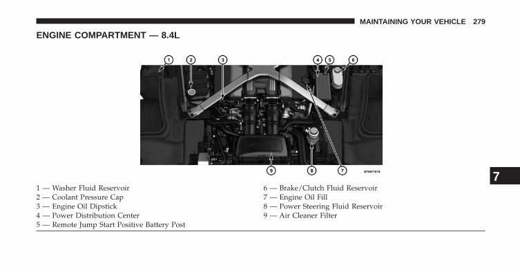
ENGINE COMPARTMENT — 8.4L
1 — Washer Fluid Reservoir 6 — Brake/Clutch Fluid Reservoir2 — Coolant Pressure Cap 7 — Engine Oil Fill3 — Engine Oil Dipstick 8 — Power Steering Fluid Reservoir4 — Power Distribution Center 9 — Air Cleaner Filter5 — Remote Jump Start Positive Battery Post
7
MAINTAINING YOUR VEHICLE 279
ONBOARD DIAGNOSTIC SYSTEM (OBD II)
To meet new government regulations and promotecleaner air, your vehicle is equipped with a sophisticatedonboard diagnostic system called OBD II. This systemmonitors the performance of the emissions and enginecontrol systems. When these systems are operating prop-erly, your vehicle will provide excellent performance andfuel economy, as well as engine emissions well withincurrent government regulations.
If any of these systems require service, the OBD II systemwill turn on the Malfunction Indicator Light. It will alsostore diagnostic codes and other information to assistyour service technician in making repairs. Although yourvehicle will usually be drivable and not need towing, seeyour authorized dealer for service as soon as possible.
CAUTION!
Prolonged driving with the light on could causefurther damage to the emission control system. Itcould also affect fuel economy and driveability. Thevehicle must be serviced before any state emissionstests can be performed.
If the light is flashing, severe catalytic converter damageand power loss will soon occur. Immediate service isrequired.
EMISSIONS INSPECTION AND MAINTENANCEPROGRAMS
In some localities, it may be a legal requirement to passan inspection of your vehicle’s emissions control system.Failure to pass could prevent vehicle registration.
For states that require an Inspection and Mainte-nance (I/M), this check verifies the “Malfunction
280 MAINTAINING YOUR VEHICLE
Indicator Light (MIL)” is functioning and is not on whenthe engine is running, and that the OBD II system isready for testing.
Normally, the OBD II system will be ready. The OBD IIsystem may not be ready if your vehicle was recentlyserviced, recently had a dead battery or a battery replace-ment. If the OBD II system should be determined notready for the I/M test, your vehicle may fail the test.
Your vehicle has a simple ignition key-actuated test,which you can use prior to going to the test station. Tocheck if your vehicle’s OBD II system is ready, you mustdo the following:
1. Cycle the ignition switch to the ON position, but donot crank or start the engine.
NOTE: If you crank or start the engine, you will have tostart this test over.
2. As soon as you cycle the ignition switch to the ONposition, you will see the MIL symbol come on as partof a normal bulb check.
3. Approximately 15 seconds later, one of two things willhappen:
• The MIL will flash for about 10 seconds and thenreturn to being fully illuminated until you turn OFFthe ignition or start the engine. This means that yourvehicle’s OBD II system is not ready and you shouldnot proceed to the I/M station.
• The MIL will not flash at all and will remain fullyilluminated until you turn OFF the ignition or start theengine. This means that your vehicle’s OBD II systemis ready and you can proceed to the I/M station.
If your OBD II system is not ready, you should see yourauthorized dealer or repair facility. If your vehicle wasrecently serviced or had a battery failure or replacement,
7
MAINTAINING YOUR VEHICLE 281
you may need to do nothing more than drive yourvehicle as you normally would in order for your OBD IIsystem to update. A recheck with the above test routinemay then indicate that the system is now ready.
Regardless of whether your vehicle’s OBD II system isready or not, if the MIL is illuminated during normalvehicle operation you should have your vehicle servicedbefore going to the I/M station. The I/M station can failyour vehicle because the MIL is on with the enginerunning.
REPLACEMENT PARTS
Use of genuine MOPAR® parts for normal/scheduledmaintenance and repairs is highly recommended to en-sure the designed performance. Damage or failurescaused by the use of non-MOPAR® parts for mainte-nance and repairs will not be covered by the New VehicleLimited Warranty.
DEALER SERVICE
Your authorized dealer has the qualified service person-nel, special tools, and equipment to perform all serviceoperations in an expert manner. Service Manuals areavailable which include detailed service information foryour vehicle. Refer to these Service Manuals beforeattempting any procedure yourself.
NOTE: Intentional tampering with emissions controlsystems may void your warranty and could result in civilpenalties being assessed against you.
WARNING!
You can be badly injured working on or around amotor vehicle. Only do service work for which youhave the knowledge and the proper equipment. Ifyou have any doubt about your ability to perform aservice job, take your vehicle to a competent me-chanic.
282 MAINTAINING YOUR VEHICLE
MAINTENANCE PROCEDURES
The pages that follow contain the required maintenanceservices determined by the engineers who designed yourvehicle.
Besides those maintenance items specified in the fixed“Maintenance Schedule”, there are other componentswhich may require servicing or replacement in the future.
CAUTION!
• Failure to properly maintain your vehicle or per-form repairs and service when necessary couldresult in more costly repairs, damage to othercomponents or negatively impact vehicle perfor-mance. Immediately have potential malfunctionsexamined by an authorized dealer or qualifiedrepair center.
(Continued)
CAUTION! (Continued)• Your vehicle has been built with improved fluids
that protect the performance and durability of yourvehicle and also allow extended maintenance inter-vals. Do not use chemical flushes in these compo-nents as the chemicals can damage your engine,transmission, power steering or air conditioning.Such damage is not covered by the New VehicleLimited Warranty. If a flush is needed because ofcomponent malfunction, use only the specifiedfluid for the flushing procedure.
7
MAINTAINING YOUR VEHICLE 283
Engine Oil
Checking Oil Level
To assure proper engine lubrication, the engine oil mustbe maintained at the correct level. Check the oil level atregular intervals, such as every fuel stop. The best time tocheck the oil level is approximately five minutes after afully warmed engine is shut off. Do not check oil levelbefore starting the engine after it has sat overnight.Checking engine oil level when the engine is cold willgive you an incorrect reading.
Checking the oil while the vehicle is on level ground alsowill improve the accuracy of the oil level readings. Addoil only when the level is below the SAFE mark.
CAUTION!
Overfilling or underfilling will cause oil aeration orloss of oil pressure. This could damage your engine.
Change Engine Oil
Refer to the “Maintenance Schedule” for the propermaintenance intervals.
NOTE: Under no circumstances should oil change inter-vals exceed 6,000 miles (10,000 km) or six months,whichever occurs first.
Engine Oil Selection
For best performance and maximum protection under alltypes of operating conditions, the manufacturer onlyrecommends full synthetic engine oils that meet therequirements of Chrysler Material Standard MS-12633.
The manufacturer recommends the use of a full synthetic0W-40 or equivalent engine oil.
284 MAINTAINING YOUR VEHICLE
CAUTION!
Do not use chemical flushes in your engine oil as thechemicals can damage your engine. Such damage isnot covered by the New Vehicle Limited Warranty.
Engine Oil Viscosity (SAE Grade)
SAE 0W-40 engine oil such as MOPAR® or PennzoilUltra is preferred for use in all operating temperatures.
The engine oil filler cap also shows the recommendedengine oil viscosity for your engine. For information onengine oil filler cap location, refer to “Engine Compart-ment” in “Maintaining Your Vehicle” for further informa-tion.
Materials Added To Engine Oil
The manufacturer strongly recommends against the ad-dition of any additives (other than leak detection dyes) tothe engine oil. Engine oil is an engineered product and itsperformance may be impaired by supplemental addi-tives.
Disposing Of Used Engine Oil And Oil Filters
Care should be taken in disposing of used engine oil andoil filters from your vehicle. Used oil and oil filters,indiscriminately discarded, can present a problem to theenvironment. Contact your authorized dealer, servicestation or governmental agency for advice on how andwhere used oil and oil filters can be safely discarded inyour area.
7
MAINTAINING YOUR VEHICLE 285
Engine Oil Filter
The engine oil filter should be replaced with a new filterat every engine oil change.
Engine Oil Filter Selection
This manufacturer’s engines have a full-flow type oilfilter. Use a filter of this type for replacement. The qualityof replacement filters varies considerably. Only highquality filters should be used to assure most efficientservice. MOPAR® engine oil filters are a high quality oilfilter and are recommended.
Engine Air Cleaner Filter
Refer to the “Maintenance Schedule” for the propermaintenance intervals.
WARNING!
The air induction system (air cleaner, hoses, etc.) canprovide a measure of protection in the case of enginebackfire. Do not remove the air induction system (aircleaner, hoses, etc.) unless such removal is necessaryfor repair or maintenance. Make sure that no one isnear the engine compartment before starting thevehicle with the air induction system (air cleaner,hoses, etc.) removed. Failure to do so can result inserious personal injury.
286 MAINTAINING YOUR VEHICLE
Engine Air Cleaner Filter Selection
The quality of replacement engine air cleaner filtersvaries considerably. Only high quality filters should beused to assure most efficient service. MOPAR® engine aircleaner filters are a high quality filter and are recom-mended.
CAUTION!
Some aftermarket air cleaners and filters can causemass air flow sensor issues which can lead to adriveability problem or a limp home condition.
Maintenance-Free Battery
The top of the maintenance-free battery is vented, andmust be replaced with a vented battery.
The battery is located underneath an access panel insidethe rear compartment on the left side of the vehicle. Aremote battery terminal is located in the engine compart-ment for jump-starting. Refer to “Jump-Starting Proce-dures” in “What To Do In Emergencies” for furtherinformation.
To gain access to the battery, remove the floor portion ofthe rear compartment carpet.
7
MAINTAINING YOUR VEHICLE 287
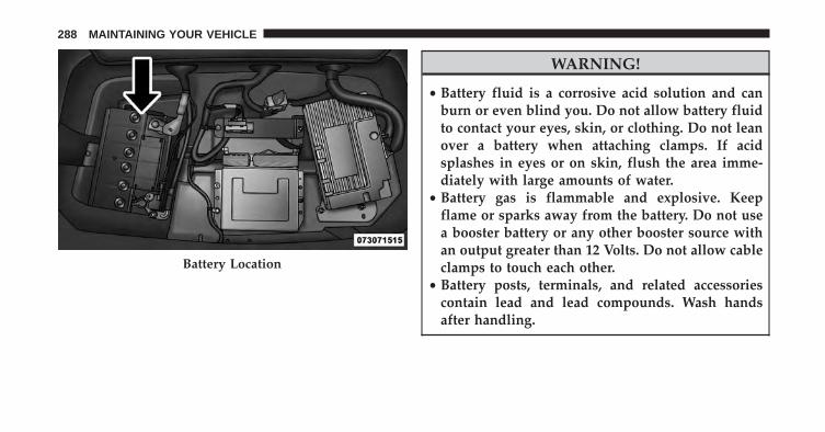
WARNING!
• Battery fluid is a corrosive acid solution and canburn or even blind you. Do not allow battery fluidto contact your eyes, skin, or clothing. Do not leanover a battery when attaching clamps. If acidsplashes in eyes or on skin, flush the area imme-diately with large amounts of water.
• Battery gas is flammable and explosive. Keepflame or sparks away from the battery. Do not usea booster battery or any other booster source withan output greater than 12 Volts. Do not allow cableclamps to touch each other.
• Battery posts, terminals, and related accessoriescontain lead and lead compounds. Wash handsafter handling.
Battery Location
288 MAINTAINING YOUR VEHICLE
CAUTION!
• It is essential when replacing the cables on thebattery that the positive cable is attached to thepositive post and the negative cable is attached tothe negative post. Battery posts are marked positive(+) and negative (-) and are identified on thebattery case. Cable clamps should be tight on theterminal posts and free of corrosion.
• If a “fast charger” is used while the battery is in thevehicle, disconnect both vehicle battery cables be-fore connecting the charger to the battery. Do notuse a “fast charger” to provide starting voltage.
Hibernation Mode
The Hibernation mode feature conserves battery powerwhen storing the vehicle. It allows for up to three monthsof storage time without losing radio and engine control-ler adaptive memory. Using this feature is an alternativeto disconnecting the battery.
NOTE: This vehicle is designed to sit in storage with afully charged battery for up to 30 days. If you plan tostore the vehicle longer than 30 days, we recommenddoing one of the following:
• Disconnect the battery.
• Use the battery charger.
• Put the vehicle into Hibernation mode (3-monthcharge).
7
MAINTAINING YOUR VEHICLE 289
To Activate Hibernation Mode
1. Cycle the ignition switch to (ACCY).
2. Select Hibernation mode within the Electronic VehicleInformation Center (EVIC).
3. Press and hold the right arrow button on the steeringwheel controls for 1 second. Vehicle will countdownfrom ten seconds and enter Hibernation Mode.
NOTE: You may press the right arrow button on thesteering wheel controls during the countdown to abortHibernation Mode.
To Deactivate Hibernation Mode
1. Press the RKE UNLOCK button to unlock the vehicle.
2. Press the ignition switch to the ON/RUN position.
Air Conditioner Maintenance
For best possible performance, your air conditionershould be checked and serviced by an authorized dealerat the start of each warm season. This service shouldinclude cleaning of the condenser fins and a performancetest. Drive belt tension should also be checked at thistime.
CAUTION!
Do not use chemical flushes in your air conditioningsystem as the chemicals can damage your air condi-tioning components. Such damage is not covered bythe New Vehicle Limited Warranty.
290 MAINTAINING YOUR VEHICLE
WARNING!
• Use only refrigerants and compressor lubricantsapproved by the manufacturer for your air condi-tioning system. Some unapproved refrigerants areflammable and can explode, injuring you. Otherunapproved refrigerants or lubricants can cause thesystem to fail, requiring costly repairs. Refer toWarranty Information Book, located on the DVD,for further warranty information.
• The air conditioning system contains refrigerantunder high pressure. To avoid risk of personalinjury or damage to the system, adding refrigerantor any repair requiring lines to be disconnectedshould be done by an experienced technician.
Refrigerant Recovery And Recycling
R-134a Air Conditioning Refrigerant is a hydrofluoro-carbon (HFC) that is endorsed by the EnvironmentalProtection Agency and is an ozone-saving product. How-ever, the manufacturer recommends that air conditioningservice be performed by authorized dealer or otherservice facilities using recovery and recycling equipment.
NOTE: Use only manufacturer approved A/C systemsealers, stop leak products, seal conditioners, compressoroil, and refrigerants.
Body Lubrication
Locks and all body pivot points, including such items asseat tracks, door hinge pivot points and rollers, liftgate,tailgate, sliding doors and hood hinges, should be lubri-cated periodically with a lithium based grease, such asMOPAR® Spray White Lube to assure quiet, easy opera-tion and to protect against rust and wear. Prior to theapplication of any lubricant, the parts concerned should
7
MAINTAINING YOUR VEHICLE 291
be wiped clean to remove dust and grit; after lubricatingexcess oil and grease should be removed. Particularattention should also be given to hood latching compo-nents to ensure proper function. When performing otherunderhood services, the hood latch, release mechanismand safety catch should be cleaned and lubricated.
The external lock cylinders should be lubricated twice ayear, preferably in the Fall and Spring. Apply a smallamount of a high quality lubricant, such as MOPAR®Lock Cylinder Lubricant directly into the lock cylinder.
Wiper Blades
Clean the rubber edges of the wiper blades and thewindshield and rear window periodically with a spongeor soft cloth and a mild nonabrasive cleaner. This willremove accumulations of salt, waxes, or road film, andhelp reduce streaking and smearing.
Operation of the wipers on dry glass for long periodsmay cause deterioration of the wiper blades. Always usewasher fluid when using the wipers to remove salt or dirtfrom a dry windshield or rear window.
Avoid using the wiper blades to remove frost or ice fromthe windshield or rear window. Make sure that they arenot frozen to the glass before turning them on to avoiddamaging the blade. Keep the blade rubber out of contactwith petroleum products such as engine oil, gasoline, etc.
NOTE: Life expectancy of wiper blades varies depend-ing on geographical area and frequency of use. Poorperformance of blades may be present with chattering,marks, water lines or wet spots. If any of these conditionsare present, clean the wiper blades or replace as neces-sary.
292 MAINTAINING YOUR VEHICLE
Adding Washer Fluid
The windshield washer fluid reservoir is located in thefront of the engine compartment on the passenger side ofthe vehicle. Be sure to check the fluid level in thereservoir at regular intervals. Fill the reservoir withwindshield washer solvent (not engine coolant (anti-freeze) and operate the system for a few seconds to flushout the residual water.
WARNING!
Commercially available windshield washer solventsare flammable. They could ignite and burn you. Caremust be exercised when filling or working aroundthe washer solution.
Exhaust System
The best protection against carbon monoxide entry intothe vehicle body is a properly maintained engine exhaustsystem.
If you notice a change in the sound of the exhaust system;or if the exhaust fumes can be detected inside the vehicle;or when the underside or rear of the vehicle is damaged;have an authorized technician inspect the complete ex-haust system and adjacent body areas for broken, dam-aged, deteriorated, or mispositioned parts. Open seamsor loose connections could permit exhaust fumes to seepinto the passenger compartment. In addition, have theexhaust system inspected each time the vehicle is raisedfor lubrication or oil change. Replace as required.
7
MAINTAINING YOUR VEHICLE 293
WARNING!
• Exhaust gases can injure or kill. They containcarbon monoxide (CO), which is colorless andodorless. Breathing it can make you unconsciousand can eventually poison you. To avoid breathingCO, refer to “Safety Tips/Exhaust Gas” in “ThingsTo Know Before Starting Your Vehicle” for furtherinformation.
• A hot exhaust system can start a fire if you parkover materials that can burn. Such materials mightbe grass or leaves coming into contact with yourexhaust system. Do not park or operate your ve-hicle in areas where your exhaust system can con-tact anything that can burn.
CAUTION!
• The catalytic converter requires the use of un-leaded fuel only. Leaded gasoline will destroy theeffectiveness of the catalyst as an emissions controldevice and may seriously reduce engine perfor-mance and cause serious damage to the engine.
• Damage to the catalytic converter can result if yourvehicle is not kept in proper operating condition.In the event of engine malfunction, particularlyinvolving engine misfire or other apparent loss ofperformance, have your vehicle serviced promptly.Continued operation of your vehicle with a severemalfunction could cause the converter to overheat,resulting in possible damage to the converter andvehicle.
294 MAINTAINING YOUR VEHICLE
Under normal operating conditions, the catalytic con-verter will not require maintenance. However, it is im-portant to keep the engine properly tuned to assureproper catalyst operation and prevent possible catalystdamage.
NOTE: Intentional tampering with emissions controlsystems can result in civil penalties being assessedagainst you.
In unusual situations involving grossly malfunctioningengine operation, a scorching odor may suggest severeand abnormal catalyst overheating. If this occurs, stopthe vehicle, turn off the engine and allow it to cool.Service, including a tune-up to manufacturer’s specifica-tions, should be obtained immediately.
To minimize the possibility of catalytic converter dam-age:
• Do not shut off the engine or interrupt the ignition,when the transmission is in gear and the vehicle is inmotion.
• Do not try to start the engine by pushing or towing thevehicle.
• Do not idle the engine with any spark plug wiresdisconnected or removed, such as when diagnostictesting, or for prolonged periods during very roughidle or malfunctioning operating conditions.
7
MAINTAINING YOUR VEHICLE 295
Cooling System
WARNING!
• When working near the radiator cooling fan, dis-connect the fan motor lead or cycle the ignitionswitch to the LOCK position. The fan is tempera-ture controlled and can start at any time the igni-tion switch is in the ON position.
• You or others can be badly burned by hot enginecoolant (antifreeze) or steam from your radiator. Ifyou see or hear steam coming from under the hood,do not open the hood until the radiator has hadtime to cool. Never try to open a cooling systempressure cap when the radiator is hot.
Coolant Checks
Check engine coolant (antifreeze) protection every 12months (before the onset of freezing weather, whereapplicable). If the engine coolant (antifreeze) is dirty, thesystem should be drained, flushed, and refilled withfresh OAT coolant (conforming to MS-12106) by anauthorized dealer. Check the front of the A/Ccondenser/radiator for any accumulation of bugs, leaves,etc. If dirty, clean by gently spraying water from a gardenhose vertically down the face of the condenser/radiator.
Check the coolant recovery bottle tubing for brittle rub-ber, cracking, tears, cuts, and tightness of the connectionat the bottle and radiator. Inspect the entire system forleaks.
With the engine at normal operating temperature (butnot running), check the cooling system pressure cap forproper vacuum sealing by draining a small amount ofengine coolant (antifreeze) from the radiator drain cock.
296 MAINTAINING YOUR VEHICLE
If the cap is sealing properly, the engine coolant (anti-freeze) will begin to drain from the coolant recoverybottle. DO NOT REMOVE THE COOLANT PRESSURECAP WHEN THE COOLING SYSTEM IS HOT.
Cooling System – Drain, Flush, And Refill
If the engine coolant (antifreeze) is dirty or contains visiblesediment, have an authorized dealer clean and flush withOAT coolant (antifreeze) (conforming to MS-12106).
Refer to the “Maintenance Schedule” for the propermaintenance intervals.
Selection Of Coolant
Refer to “Fluids, Lubricants, and Genuine Parts” in“Maintaining Your Vehicle” for further information.
CAUTION!
• Mixing of engine coolant (antifreeze) other thanspecified Organic Additive Technology (OAT) en-gine coolant (antifreeze), may result in enginedamage and may decrease corrosion protection.Organic Additive Technology (OAT) engine cool-ant is different and should not be mixed withHybrid Organic Additive Technology (HOAT) en-gine coolant (antifreeze) or any “globally compat-ible” coolant (antifreeze). If a non-OAT enginecoolant (antifreeze) is introduced into the coolingsystem in an emergency, the cooling system willneed to be drained, flushed, and refilled with freshOAT coolant (conforming to MS-12106), by anauthorized dealer as soon as possible.
(Continued)
7
MAINTAINING YOUR VEHICLE 297
CAUTION! (Continued)• Do not use water alone or alcohol-based engine
coolant (antifreeze) products. Do not use additionalrust inhibitors or antirust products, as they may notbe compatible with the radiator engine coolant andmay plug the radiator.
• This vehicle has not been designed for use withpropylene glycol-based engine coolant (antifreeze).Use of propylene glycol-based engine coolant (an-tifreeze) is not recommended.
Adding Coolant
Your vehicle has been built with an improved enginecoolant (OAT coolant conforming to MS-12106) thatallows extended maintenance intervals. This engine cool-ant (antifreeze) can be used up to ten years or 150,000miles (240,000 km) before replacement. To prevent reduc-ing this extended maintenance period, it is important that
you use the same engine coolant (OAT coolant conform-ing to MS-12106) throughout the life of your vehicle.
Please review these recommendations for using OrganicAdditive Technology (OAT) engine coolant (antifreeze)that meets the requirements of Chrysler Material Stan-dard MS-12106. When adding engine coolant (antifreeze):
• We recommend using MOPAR® Antifreeze/Coolant10 Year/150,000 Mile Formula OAT (Organic AdditiveTechnology) that meets the requirements of ChryslerMaterial Standard MS-12106.
• Mix a minimum solution of 50% OAT engine coolantthat meets the requirements of Chrysler Material Stan-dard MS-12106 and distilled water. Use higher concen-trations (not to exceed 70%) if temperatures below−34° F (−37° C) are anticipated.
• Use only high purity water such as distilled or deion-ized water when mixing the water/engine coolant
298 MAINTAINING YOUR VEHICLE
(antifreeze) solution. The use of lower quality waterwill reduce the amount of corrosion protection in theengine cooling system.
Please note that it is the owner’s responsibility to main-tain the proper level of protection against freezing ac-cording to the temperatures occurring in the area wherethe vehicle is operated.
NOTE: Mixing engine coolant (antifreeze) types is notrecommended and can result in cooling system damage.If HOAT and OAT coolant are mixed in an emergency,have a authorized dealer drain, flush, and refill with OATcoolant (conforming to MS-12106) as soon as possible.
Cooling System Pressure Cap
The cap must be fully tightened to prevent loss of enginecoolant (antifreeze), and to insure that engine coolant(antifreeze) will return to the radiator from the coolantrecovery bottle.
The cap should be inspected and cleaned if there is anyaccumulation of foreign material on the sealing surfaces.
WARNING!
• The warning words “DO NOT OPEN HOT” on thecooling system pressure cap are a safety precaution.Never add engine coolant (antifreeze) when theengine is overheated. Do not loosen or remove thecap to cool an overheated engine. Heat causespressure to build up in the cooling system. Toprevent scalding or injury, do not remove thepressure cap while the system is hot or underpressure.
• Do not use a pressure cap other than the onespecified for your vehicle. Personal injury or en-gine damage may result.
7
MAINTAINING YOUR VEHICLE 299
Disposal Of Used Engine Coolant
Used ethylene glycol-based engine coolant (antifreeze) isa regulated substance requiring proper disposal. Checkwith your local authorities to determine the disposalrules for your community. To prevent ingestion by ani-mals or children, do not store ethylene glycol-basedengine coolant (antifreeze) in open containers or allow itto remain in puddles on the ground. If ingested by a childor pet, seek emergency assistance immediately. Clean upany ground spills immediately.
Coolant Level
The coolant bottle provides a quick visual method fordetermining that the coolant level is adequate. With theengine OFF and cold, the level of the engine coolant(antifreeze) in the bottle should be between the rangesindicated on the bottle.
The radiator normally remains completely full, so there isno need to remove the radiator cap unless checking for
engine coolant (antifreeze) freeze point or replacing cool-ant. Advise your service attendant of this. As long as theengine operating temperature is satisfactory, the coolantbottle need only be checked once a month.
When additional engine coolant (antifreeze) is needed tomaintain the proper level, only OAT coolant that meetsthe requirements of Chrysler Material Standard MS-12106 should be added to the coolant bottle. Do notoverfill.
Points To Remember
NOTE: When the vehicle is stopped after a few miles/kilometers of operation, you may observe vapor comingfrom the front of the engine compartment. This is nor-mally a result of moisture from rain, snow, or highhumidity accumulating on the radiator and being vapor-ized when the thermostat opens, allowing hot enginecoolant (antifreeze) to enter the radiator.
300 MAINTAINING YOUR VEHICLE
If an examination of your engine compartment shows noevidence of radiator or hose leaks, the vehicle may besafely driven. The vapor will soon dissipate.
• Do not overfill the coolant expansion bottle.
• Check the coolant freeze point in the radiator and inthe coolant expansion bottle. If engine coolant (anti-freeze) needs to be added, the contents of the coolantexpansion bottle must also be protected against freez-ing.
• If frequent engine coolant (antifreeze) additions arerequired, the cooling system should be pressure testedfor leaks.
• Maintain engine coolant (antifreeze) concentration at aminimum of 50% OAT coolant (conforming to MS-12106) and distilled water for proper corrosion protec-tion of your engine which contains aluminum compo-nents.
• Make sure that the coolant expansion bottle overflowhoses are not kinked or obstructed.
• Keep the front of the radiator clean. If your vehicle isequipped with air conditioning, keep the front of thecondenser clean.
• Do not change the thermostat for Summer or Winteroperation. If replacement is ever necessary, installONLY the correct type thermostat. Other designs mayresult in unsatisfactory engine coolant (antifreeze)performance, poor gas mileage, and increased emis-sions.
7
MAINTAINING YOUR VEHICLE 301
Brake System
To ensure brake system performance, all brake systemcomponents should be inspected periodically. Refer to“Maintenance Schedule” for the proper maintenanceintervals.
WARNING!
Riding the brakes can lead to brake failure andpossibly an accident. Driving with your foot restingor riding on the brake pedal can result in abnormallyhigh brake temperatures, excessive lining wear, andpossible brake damage. You would not have your fullbraking capacity in an emergency.
Master Cylinder – Brake Fluid Level Check
Check the fluid level in the master cylinder immediately ifthe brake system warning light indicates system failure.
Check the fluid level in the master cylinder when per-forming underhood services.
Clean the top of the master cylinder area before removingthe cap. If necessary, add fluid to bring the fluid level up tothe requirements described on the brake fluid reservoir.
Overfilling of fluid is not recommended because it maycause leaking in the system.
With disc brakes, fluid level can be expected to fall as thebrake pads wear. However, low fluid level may be causedby a leak and a checkup may be needed.
Use only the manufacturer’s recommended brake fluid.Refer to “Fluids, Lubricants, and Genuine Parts” in“Maintaining Your Vehicle” for further information. Use
302 MAINTAINING YOUR VEHICLE
of a brake fluid that may have a lower initial boilingpoint or unidentified as to specification, may result insudden brake failure during hard prolonged braking.
WARNING!
• Use only manufacturer’s recommended brakefluid. Refer to “Fluids, Lubricants, and GenuineParts” in “Maintaining Your Vehicle” for furtherinformation. Using the wrong type of brake fluidcan severely damage your brake system and/orimpair its performance. The proper type of brakefluid for your vehicle is also identified on theoriginal factory installed hydraulic master cylinderreservoir.
(Continued)
WARNING! (Continued)• To avoid contamination from foreign matter or
moisture, use only new brake fluid or fluid that hasbeen in a tightly closed container. Keep the mastercylinder reservoir cap secured at all times. Brakefluid in a open container absorbs moisture from theair resulting in a lower boiling point. This maycause it to boil unexpectedly during hard or pro-longed braking, resulting in sudden brake failure.This could result in a accident.
• Overfilling the brake fluid reservoir can result inspilling brake fluid on hot engine parts, causingthe brake fluid to catch fire. Brake fluid can alsodamage painted and vinyl surfaces, care should betaken to avoid its contact with these surfaces.
(Continued)
7
MAINTAINING YOUR VEHICLE 303
WARNING! (Continued)• Do not allow petroleum based fluid to contaminate
the brake fluid. Brake seal components could bedamaged, causing partial or complete brake failure.This could result in an accident.
Change Brake Fluid
Brake fluid will tend to absorb moisture from the atmo-sphere over time. If the fluid becomes contaminated withwater, brake performance will deteriorate. Therefore, thebrake fluid must be changed at the intervals specified inthe “Maintenance Schedule.” Refer to “MaintenanceSchedule” for further information. See your authorizeddealer for service.
Manual Transmission
Transmission Fluid Level Check
Check the fluid in the transmission when performingother underbody services.
Check the fluid level by removing the fill plug located onthe left side of the transmission. The fluid level should beapproximately 1/4 in (6.4 mm) below the bottom of thefill hole. Add fluid, if necessary, to maintain the properlevel. Refer to “Fluids, Lubricants, and Genuine Parts” in“Maintaining Your Vehicle” for further information.
NOTE: DO NOT overfill transmission, damage canoccur.
304 MAINTAINING YOUR VEHICLE
CAUTION!
Using a transmission fluid other than the manufac-turer’s recommended fluid may cause deteriorationin transmission shift quality and/or damage to thetransmission. Refer to “Fluids, Lubricants, andGenuine Parts” in this section for fluid specifica-tions.
Change Transmission Fluid
Refer to “Maintenance Schedule” for the proper mainte-nance intervals. If contaminated with water, change thefluid immediately. See your authorized dealer for service.
Hydraulic Clutch
Master Cylinder – Clutch Fluid Level Check
The clutch hydraulic system is fed by a segregatedvolume of fluid within the brake system master cylinderreservoir. In the event of leakage or wear, use only the
manufacturer’s recommended brake fluid. Refer to “Flu-ids, Lubricants, and Genuine Parts” in “Maintaining YourVehicle” for further information.
Rear Axle
Axle Lubricant Level Check
Check the exterior of the axle for evidence of gear oilleakage every 12 months or 6,000 miles (10 000 km). Thischeck should be made with the vehicle level and on theground or raised on an axle and wheel type hoist. Theaxle lubricant level should be between the bottom of thefiller plug and a point approximately 3/8 inch (9.5 mm)below the filler plug. If adding axle lubricant, use onlythe manufacturer’s recommended axle lubricant. Refer to“Fluids, Lubricants, and Genuine Parts” in “MaintainingYour Vehicle” for further information.
7
MAINTAINING YOUR VEHICLE 305
CAUTION!
Using axle fluid other than the manufactured recom-mended fluid may cause a shudder/noise issue. referto “Fluids Lubes and Genuine Parts” in “ Maintain-ing Your Vehicle” for further information.
Change Axle Lubricant
Refer to “Maintenance Schedule” for the proper mainte-nance intervals. Change the lubricant immediately ifcontaminated with water. See your authorized dealer forservice.
Appearance Care And Protection From Corrosion
Protection Of Body And Paint From Corrosion
Vehicle body care requirements vary according to geo-graphic locations and usage. Chemicals that make roadspassable in snow and ice, and chemicals that are sprayedon trees and road surfaces during other seasons, are
highly corrosive to the metal in your vehicle. Outsideparking, which exposes your vehicle to airborne contami-nants, road surfaces on which the vehicle is operated,extreme hot or cold weather and other extreme condi-tions will have an adverse effect on paint, metal trim, andunderbody protection.
The following maintenance recommendations will enableyou to obtain maximum benefit from the corrosionresistance built into your vehicle.
Washing
• Wash your vehicle regularly. Always wash your ve-hicle in the shade using MOPAR® Car Wash, or a mildcar wash soap, and rinse the panels completely withclear water.
• If insects, tar, or other similar deposits have accumu-lated on your vehicle, use MOPAR® Super Kleen Bugand Tar Remover to remove.
306 MAINTAINING YOUR VEHICLE
• Use a high quality cleaner wax, such as MOPAR®Cleaner Wax to remove road film, stains and to protectyour paint finish. Take care never to scratch the paint.
• Avoid using abrasive compounds and power buffing thatmay diminish the gloss or thin out the paint finish.
CAUTION!
• Do not use abrasive or strong cleaning materialssuch as steel wool or scouring powder that willscratch metal and painted surfaces.
• Use of power washers exceeding 1,200 psi (8 274kPa) can result in damage or removal of paint anddecals.
Wheel And Wheel Trim Care
• All wheels and wheel trim, especially aluminum andchrome plated wheels, should be cleaned regularlywith a mild soap and water to prevent corrosion.
• To remove heavy soil and/or excessive brake dust, useMOPAR® Wheel Cleaner.
CAUTION!
Do not use scouring pads, steel wool, a bristle brush,or metal polishes. Do not use oven cleaner. Theseproducts may damage the wheel’s protective finish.Avoid automatic car washes that use acidic solutionsor harsh brushes that may damage the wheel’s pro-tective finish. Only MOPAR® Wheel Cleaner orequivalent is recommended.
7
MAINTAINING YOUR VEHICLE 307
Interior Care
Use MOPAR® Total Clean to clean fabric upholstery andcarpeting.
Use MOPAR® Total Clean to clean vinyl upholstery.
MOPAR® Total Clean is specifically recommended forleather upholstery.
Your leather upholstery can be best preserved by regularcleaning with a damp soft cloth. Small particles of dirtcan act as an abrasive and damage the leather upholsteryand should be removed promptly with a damp cloth.Stubborn soils can be removed easily with a soft clothand MOPAR® Total Clean. Care should be taken to avoidsoaking your leather upholstery with any liquid. Pleasedo not use polishes, oils, cleaning fluids, solvents, deter-gents, or ammonia-based cleaners to clean your leatherupholstery. Application of a leather conditioner is notrequired to maintain the original condition.
WARNING!
Do not use volatile solvents for cleaning purposes.Many are potentially flammable, and if used inclosed areas they may cause respiratory harm.
CAUTION!
Do not use Alcohol and Alcohol-based and/or Ketonbased cleaning products to clean leather seats, asdamage to the seat may result.
Leather or Vinyl Seat/Trim Care and Cleaning
Leather is best preserved by regular cleaning with adamp soft cloth. Small particles of dirt can act as anabrasive and damage the leather surface and should beremoved immediately with a damp cloth. Stubborn soilscan be removed easily with a soft cloth and MOPAR®Total Clean or equivalent. Care should be taken to avoid
308 MAINTAINING YOUR VEHICLE
soaking the leather with any liquid. Please do not usepolishes, oils, cleaning fluids, solvents, detergents, orammonia-based cleaners to clean the leather. Applicationof a leather conditioner is not required to maintain theoriginal condition.
Glass Surfaces
All glass surfaces should be cleaned on a regular basiswith MOPAR® Glass Cleaner, or any commercialhousehold-type glass cleaner. Never use an abrasive typecleaner. Use caution when cleaning the inside rear win-dow equipped with electric defrosters or the right rearquarter window equipped with the radio antenna. Donot use scrapers or other sharp instrument that mayscratch the elements.
When cleaning the rear view mirror, spray cleaner on thetowel or rag that you are using. Do not spray cleanerdirectly on the mirror.
Cleaning Plastic Instrument Cluster Lenses
The lenses in front of the instruments in this vehicle aremolded in clear plastic. When cleaning the lenses, caremust be taken to avoid scratching the plastic.
1. Clean with a wet soft rag. A mild soap solution may beused, but do not use high alcohol content or abrasivecleaners. If soap is used, wipe clean with a clean damprag.
2. Dry with a soft cloth.
Seat Belt Maintenance
Do not bleach, dye or clean the belts with chemicalsolvents or abrasive cleaners. This will weaken the fabric.Sun damage can also weaken the fabric.
If the belts need cleaning, use a mild soap solution orlukewarm water. Do not remove the belts from the car towash them. Dry with a soft cloth.
7
MAINTAINING YOUR VEHICLE 309
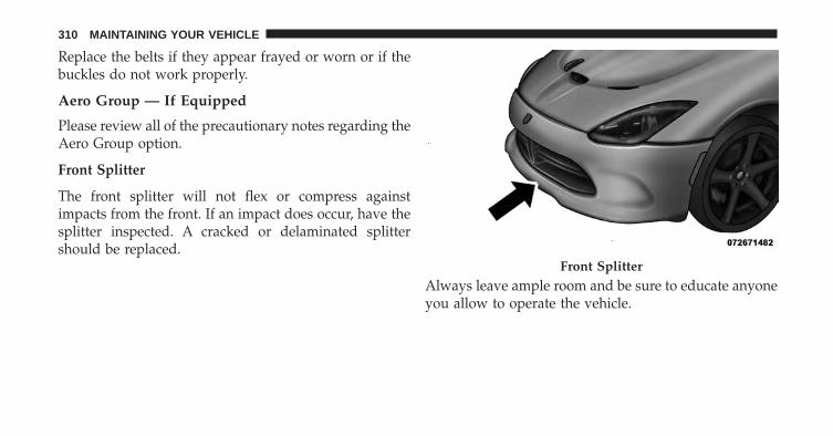
Replace the belts if they appear frayed or worn or if thebuckles do not work properly.
Aero Group — If Equipped
Please review all of the precautionary notes regarding theAero Group option.
Front Splitter
The front splitter will not flex or compress againstimpacts from the front. If an impact does occur, have thesplitter inspected. A cracked or delaminated splittershould be replaced.
Always leave ample room and be sure to educate anyoneyou allow to operate the vehicle.
Front Splitter
310 MAINTAINING YOUR VEHICLE
CAUTION!
Use care when approaching parking blocks, tallspeed bumps and garage curbs. These surfaces candamage your splitter.
Use caution when driving up to sloped surfaces or overspeed bumps. Approaching a speed bump or a slope at aslight angle may improve your clearance.
CAUTION!
• Hard contact with steep ramps may cause damageto your splitter.
• Replace rub strips when they are worn down to 3/8inch (10 mm) on the front edge. This will avoiddamage to the carbon fiber panel
FUSES
WARNING!
• When replacing a blown fuse, always use an ap-propriate replacement fuse with the same amprating as the original fuse. Never replace a fusewith another fuse of higher amp rating. Neverreplace a blown fuse with metal wires or any othermaterial. Failure to use proper fuses may result inserious personal injury, fire and/or property dam-age.
• Before replacing a fuse, make sure that the ignitionis off and that all the other services are switched offand/or disengaged.
7
MAINTAINING YOUR VEHICLE 311
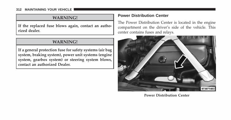
WARNING!
If the replaced fuse blows again, contact an autho-rized dealer.
WARNING!
If a general protection fuse for safety systems (air bagsystem, braking system), power unit systems (enginesystem, gearbox system) or steering system blows,contact an authorized Dealer.
Power Distribution Center
The Power Distribution Center is located in the enginecompartment on the driver’s side of the vehicle. Thiscenter contains fuses and relays.
Power Distribution Center
312 MAINTAINING YOUR VEHICLE
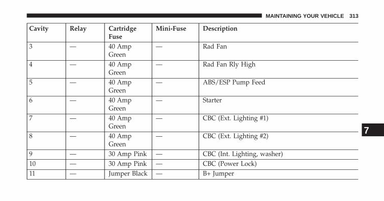
Cavity Relay CartridgeFuse
Mini-Fuse Description
3 — 40 AmpGreen
— Rad Fan
4 — 40 AmpGreen
— Rad Fan Rly High
5 — 40 AmpGreen
— ABS/ESP Pump Feed
6 — 40 AmpGreen
— Starter
7 — 40 AmpGreen
— CBC (Ext. Lighting #1)
8 — 40 AmpGreen
— CBC (Ext. Lighting #2)
9 — 30 Amp Pink — CBC (Int. Lighting, washer)10 — 30 Amp Pink — CBC (Power Lock)11 — Jumper Black — B+ Jumper
7
MAINTAINING YOUR VEHICLE 313
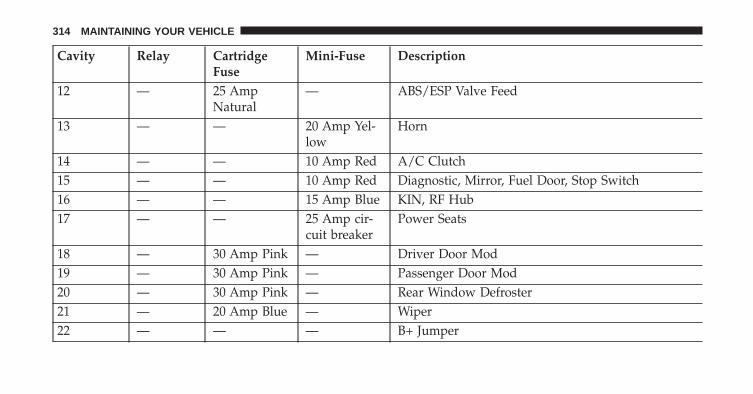
Cavity Relay CartridgeFuse
Mini-Fuse Description
12 — 25 AmpNatural
— ABS/ESP Valve Feed
13 — — 20 Amp Yel-low
Horn
14 — — 10 Amp Red A/C Clutch15 — — 10 Amp Red Diagnostic, Mirror, Fuel Door, Stop Switch16 — — 15 Amp Blue KIN, RF Hub17 — — 25 Amp cir-
cuit breakerPower Seats
18 — 30 Amp Pink — Driver Door Mod19 — 30 Amp Pink — Passenger Door Mod20 — 30 Amp Pink — Rear Window Defroster21 — 20 Amp Blue — Wiper22 — — — B+ Jumper
314 MAINTAINING YOUR VEHICLE
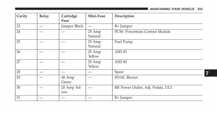
Cavity Relay CartridgeFuse
Mini-Fuse Description
23 — Jumper Black — B+ Jumper24 — — 25 Amp
NaturalPCM- Powertrain Control Module
25 — — 25 AmpNatural
Fuel Pump
26 — — 20 AmpYellow
ASD #1
27 — — 20 AmpYellow
ASD #2
28 — — — Spare29 — 40 Amp
Green— HVAC Blower
30 — 20 Amp Yel-low
— RR Power Outlet, Adj. Pedals, UCI
31 — — — B+ Jumper
7
MAINTAINING YOUR VEHICLE 315
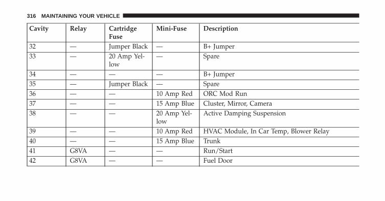
Cavity Relay CartridgeFuse
Mini-Fuse Description
32 — Jumper Black — B+ Jumper33 — 20 Amp Yel-
low— Spare
34 — — — B+ Jumper35 — Jumper Black — Spare36 — — 10 Amp Red ORC Mod Run37 — — 15 Amp Blue Cluster, Mirror, Camera38 — — 20 Amp Yel-
lowActive Damping Suspension
39 — — 10 Amp Red HVAC Module, In Car Temp, Blower Relay40 — — 15 Amp Blue Trunk41 G8VA — — Run/Start42 G8VA — — Fuel Door
316 MAINTAINING YOUR VEHICLE
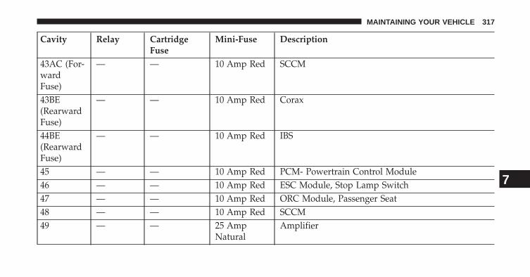
Cavity Relay CartridgeFuse
Mini-Fuse Description
43AC (For-wardFuse)
— — 10 Amp Red SCCM
43BE(RearwardFuse)
— — 10 Amp Red Corax
44BE(RearwardFuse)
— — 10 Amp Red IBS
45 — — 10 Amp Red PCM- Powertrain Control Module46 — — 10 Amp Red ESC Module, Stop Lamp Switch47 — — 10 Amp Red ORC Module, Passenger Seat48 — — 10 Amp Red SCCM49 — — 25 Amp
NaturalAmplifier
7
MAINTAINING YOUR VEHICLE 317
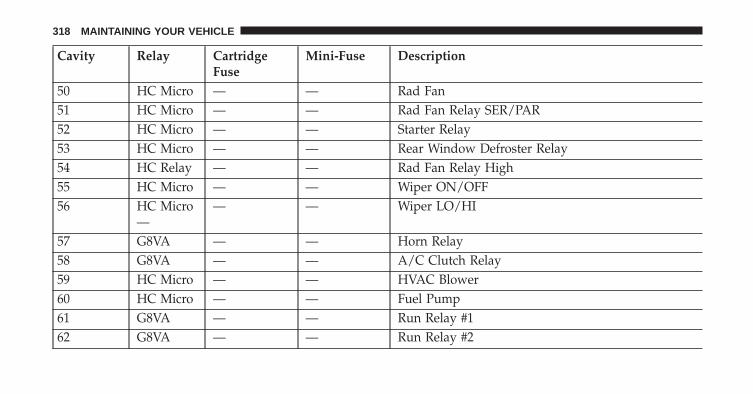
Cavity Relay CartridgeFuse
Mini-Fuse Description
50 HC Micro — — Rad Fan51 HC Micro — — Rad Fan Relay SER/PAR52 HC Micro — — Starter Relay53 HC Micro — — Rear Window Defroster Relay54 HC Relay — — Rad Fan Relay High55 HC Micro — — Wiper ON/OFF56 HC Micro
—— — Wiper LO/HI
57 G8VA — — Horn Relay58 G8VA — — A/C Clutch Relay59 HC Micro — — HVAC Blower60 HC Micro — — Fuel Pump61 G8VA — — Run Relay #162 G8VA — — Run Relay #2
318 MAINTAINING YOUR VEHICLE
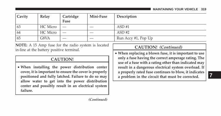
Cavity Relay CartridgeFuse
Mini-Fuse Description
63 HC Micro — — ASD #164 HC Micro — — ASD #265 G8VA — — Run Accy #1, Pop Up
NOTE: A 15 Amp fuse for the radio system is locatedin-line at the battery positive terminal.
CAUTION!
• When installing the power distribution centercover, it is important to ensure the cover is properlypositioned and fully latched. Failure to do so mayallow water to get into the power distributioncenter and possibly result in an electrical systemfailure.
(Continued)
CAUTION! (Continued)• When replacing a blown fuse, it is important to use
only a fuse having the correct amperage rating. Theuse of a fuse with a rating other than indicated mayresult in a dangerous electrical system overload. Ifa properly rated fuse continues to blow, it indicatesa problem in the circuit that must be corrected. 7
MAINTAINING YOUR VEHICLE 319
VEHICLE STORAGE
We recommend that you follow these guidelines forstoring your vehicle for extended periods.
• Fill the fuel tank. This will prevent water condensationinside the tank. If you plan to store your vehicle morethan two months, add an anti-oxidant fuel stabilizer tothe fuel tank.
• Change the oil to remove any corrosive combustionrelated acids in the crankcase.
• Check that the radiator coolant level of protection is toat least -20°F (-29°C).
• Make sure that all tires are inflated to the optimumpressure.
• Wash and wax the vehicle to protect the finish.
• Store the vehicle in a dry, well-ventilated location.
• Move the wiper blades away from the windshield.
• Block the wheels. Do not apply the parking brake.
• Cut blocks of plywood about the same size of the tires.Cover each block with indoor/outdoor carpeting andplace them between the tires and concrete. This willprevent tire flat spotting.
• For long-term storage, remove the tires and put thevehicle up on blocks. Stack the tires on plywood andcover with a tarp to prevent flat spotting.
• If the vehicle will be subjected to freezing tempera-tures, either remove the battery and store it in a dry,well ventilated area or connect a trickle charger (1.5Amp) with automatic shutdown / overcharge protec-tion to the battery. However, do not leave the tricklecharger hooked up to the battery without beingplugged in to a 110 Volt AC outlet, as this will result infurther drain on the vehicle’s battery. If the vehicle isnot going to be driven in the next three weeks, performthe battery recharge procedure in the Service Manual.
320 MAINTAINING YOUR VEHICLE
Then, either disconnect the battery at the negativeterminal or use the “Battery Save Feature” to conservebattery power. Refer to “Maintenance Procedures/Battery Save Feature” in “Maintaining Your Vehicle”for further information.
• Cover the vehicle whenever possible to prevent acci-dental damage to the finish.
NOTE: Disconnecting the battery causes the engine con-trol system to lose memory of some “learned” functions.After reconnecting the battery, the engine may run roughuntil the control module “relearns” these functions. Us-ing the Battery Save Feature will prevent the enginecontroller from loosing its memory.
CAUTION!
Use care when disconnecting the remote positivecable. It is connected to the battery and can short outto any metal on the vehicle. Always tape or wrap theexposed cable end to prevent electrical shorts.
Check the battery every four to six weeks to ensure thatthe voltage is above 12.10 Volts. The voltage will dropmore rapidly in hot temperatures. If battery voltagedrops below 12.10 Volts, follow the battery rechargeprocedure in the Service Manual.
7
MAINTAINING YOUR VEHICLE 321
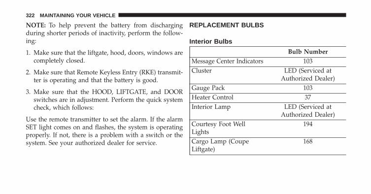
NOTE: To help prevent the battery from dischargingduring shorter periods of inactivity, perform the follow-ing:
1. Make sure that the liftgate, hood, doors, windows arecompletely closed.
2. Make sure that Remote Keyless Entry (RKE) transmit-ter is operating and that the battery is good.
3. Make sure that the HOOD, LIFTGATE, and DOORswitches are in adjustment. Perform the quick systemcheck, which follows:
Use the remote transmitter to set the alarm. If the alarmSET light comes on and flashes, the system is operatingproperly. If not, there is a problem with a switch or thesystem. See your authorized dealer for service.
REPLACEMENT BULBS
Interior Bulbs
Bulb NumberMessage Center Indicators 103Cluster LED (Serviced at
Authorized Dealer)Gauge Pack 103Heater Control 37Interior Lamp LED (Serviced at
Authorized Dealer)Courtesy Foot WellLights
194
Cargo Lamp (CoupeLiftgate)
168
322 MAINTAINING YOUR VEHICLE
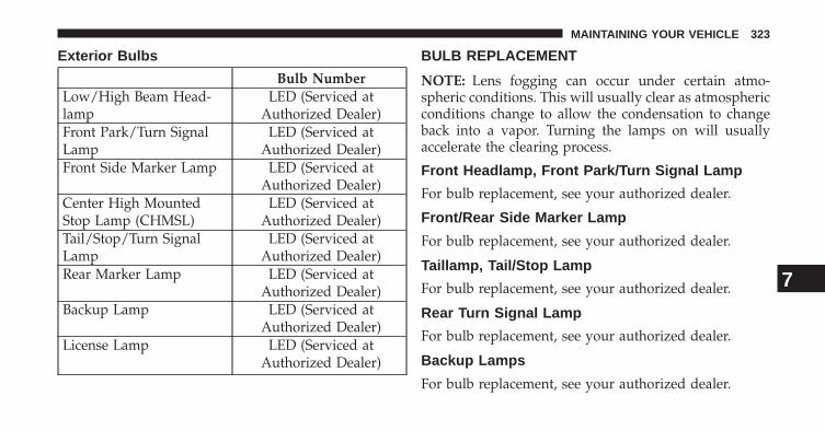
Exterior Bulbs
Bulb NumberLow/High Beam Head-lamp
LED (Serviced atAuthorized Dealer)
Front Park/Turn SignalLamp
LED (Serviced atAuthorized Dealer)
Front Side Marker Lamp LED (Serviced atAuthorized Dealer)
Center High MountedStop Lamp (CHMSL)
LED (Serviced atAuthorized Dealer)
Tail/Stop/Turn SignalLamp
LED (Serviced atAuthorized Dealer)
Rear Marker Lamp LED (Serviced atAuthorized Dealer)
Backup Lamp LED (Serviced atAuthorized Dealer)
License Lamp LED (Serviced atAuthorized Dealer)
BULB REPLACEMENT
NOTE: Lens fogging can occur under certain atmo-spheric conditions. This will usually clear as atmosphericconditions change to allow the condensation to changeback into a vapor. Turning the lamps on will usuallyaccelerate the clearing process.
Front Headlamp, Front Park/Turn Signal Lamp
For bulb replacement, see your authorized dealer.
Front/Rear Side Marker Lamp
For bulb replacement, see your authorized dealer.
Taillamp, Tail/Stop Lamp
For bulb replacement, see your authorized dealer.
Rear Turn Signal Lamp
For bulb replacement, see your authorized dealer.
Backup Lamps
For bulb replacement, see your authorized dealer.
7
MAINTAINING YOUR VEHICLE 323
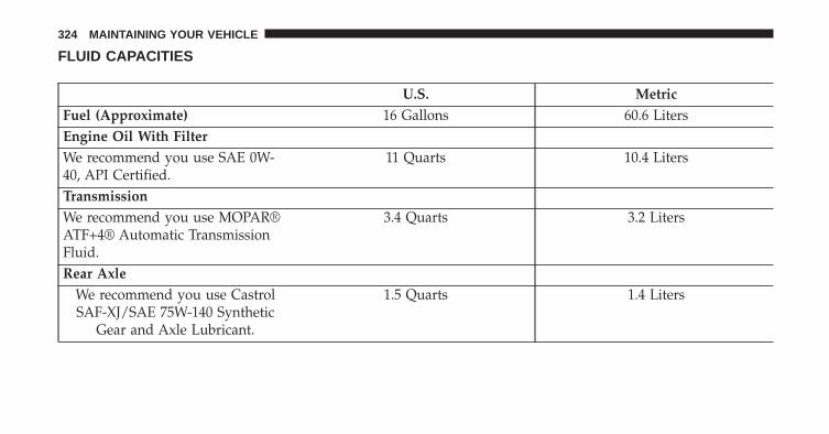
FLUID CAPACITIES
U.S. MetricFuel (Approximate) 16 Gallons 60.6 LitersEngine Oil With FilterWe recommend you use SAE 0W-40, API Certified.
11 Quarts 10.4 Liters
TransmissionWe recommend you use MOPAR®ATF+4® Automatic TransmissionFluid.
3.4 Quarts 3.2 Liters
Rear AxleWe recommend you use CastrolSAF-XJ/SAE 75W-140 Synthetic
Gear and Axle Lubricant.
1.5 Quarts 1.4 Liters
324 MAINTAINING YOUR VEHICLE
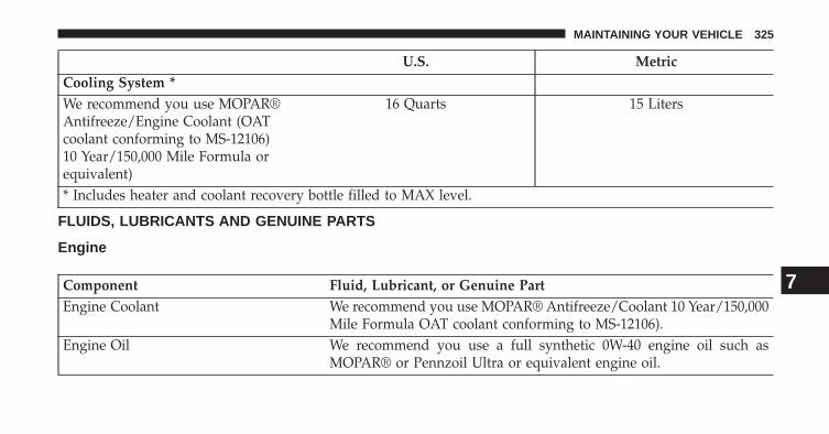
U.S. MetricCooling System *We recommend you use MOPAR®Antifreeze/Engine Coolant (OATcoolant conforming to MS-12106)10 Year/150,000 Mile Formula orequivalent)
16 Quarts 15 Liters
* Includes heater and coolant recovery bottle filled to MAX level.
FLUIDS, LUBRICANTS AND GENUINE PARTS
Engine
Component Fluid, Lubricant, or Genuine PartEngine Coolant We recommend you use MOPAR® Antifreeze/Coolant 10 Year/150,000
Mile Formula OAT coolant conforming to MS-12106).Engine Oil We recommend you use a full synthetic 0W-40 engine oil such as
MOPAR® or Pennzoil Ultra or equivalent engine oil.
7
MAINTAINING YOUR VEHICLE 325
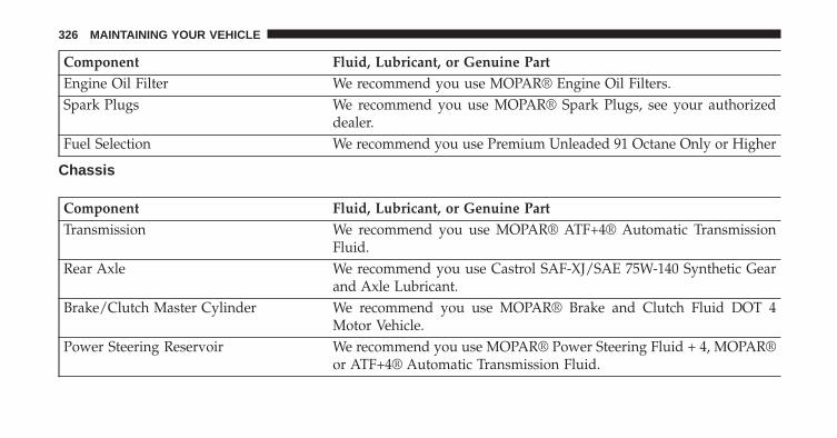
Component Fluid, Lubricant, or Genuine PartEngine Oil Filter We recommend you use MOPAR® Engine Oil Filters.Spark Plugs We recommend you use MOPAR® Spark Plugs, see your authorized
dealer.Fuel Selection We recommend you use Premium Unleaded 91 Octane Only or Higher
Chassis
Component Fluid, Lubricant, or Genuine PartTransmission We recommend you use MOPAR® ATF+4® Automatic Transmission
Fluid.Rear Axle We recommend you use Castrol SAF-XJ/SAE 75W-140 Synthetic Gear
and Axle Lubricant.Brake/Clutch Master Cylinder We recommend you use MOPAR® Brake and Clutch Fluid DOT 4
Motor Vehicle.Power Steering Reservoir We recommend you use MOPAR® Power Steering Fluid + 4, MOPAR®
or ATF+4® Automatic Transmission Fluid.
326 MAINTAINING YOUR VEHICLE
MAINTENANCE SCHEDULES
CONTENTS� MAINTENANCE SCHEDULES . . . . . . . . . . . . .328
▫ Required Maintenance Intervals . . . . . . . . . . .329
8
MAINTENANCE
SCHEDULES
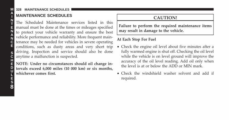
MAINTENANCE SCHEDULES
The Scheduled Maintenance services listed in thismanual must be done at the times or mileages specifiedto protect your vehicle warranty and ensure the bestvehicle performance and reliability. More frequent main-tenance may be needed for vehicles in severe operatingconditions, such as dusty areas and very short tripdriving. Inspection and service should also be doneanytime a malfunction is suspected.
NOTE: Under no circumstances should oil change in-tervals exceed 6,000 miles (10 000 km) or six months,whichever comes first.
CAUTION!
Failure to perform the required maintenance itemsmay result in damage to the vehicle.
At Each Stop For Fuel
• Check the engine oil level about five minutes after afully warmed engine is shut off. Checking the oil levelwhile the vehicle is on level ground will improve theaccuracy of the oil level reading. Add oil only whenthe level is at or below the ADD or MIN mark.
• Check the windshield washer solvent and add ifrequired.
8
MAINTENANCE
SCHEDULES
328 MAINTENANCE SCHEDULES
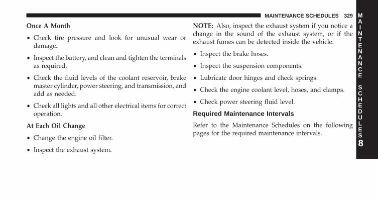
Once A Month
• Check tire pressure and look for unusual wear ordamage.
• Inspect the battery, and clean and tighten the terminalsas required.
• Check the fluid levels of the coolant reservoir, brakemaster cylinder, power steering, and transmission, andadd as needed.
• Check all lights and all other electrical items for correctoperation.
At Each Oil Change
• Change the engine oil filter.
• Inspect the exhaust system.
NOTE: Also, inspect the exhaust system if you notice achange in the sound of the exhaust system, or if theexhaust fumes can be detected inside the vehicle.
• Inspect the brake hoses.
• Inspect the suspension components.
• Lubricate door hinges and check springs.
• Check the engine coolant level, hoses, and clamps.
• Check power steering fluid level.
Required Maintenance Intervals
Refer to the Maintenance Schedules on the followingpages for the required maintenance intervals.
8
MAINTENANCE
SCHEDULES
MAINTENANCE SCHEDULES 329

6,000 Miles (10,000 km) or 6Months Maintenance ServiceSchedule❏ Change the engine oil and engine oil
filter.❏ Rotate tires.
Odometer Reading Date
Repair Order # Dealer Code
Signature, Authorized Service Center
12,000 Miles (20,000 km) or 12 Months Maintenance ServiceSchedule❏ Change the engine oil and engine oil filter.❏ Rotate tires.❏ Replace the air conditioning filter (if equipped).❏ Inspect the brake linings, and replace if necessary.❏ Inspect the exhaust system. Perform the first inspection at 12,000 miles (20 000 km)
or 12 months.❏ Inspect the manual transmission fluid, add as necessary.❏ Inspect the front suspension and tie rod ends for cracks or leaks and all parts for
damage, wear, improper looseness or end play; replace if necessary.
Odometer Reading Date
Repair Order # Dealer Code
Signature, Authorized Service Center
8
MAINTENANCE
SCHEDULES
330 MAINTENANCE SCHEDULES
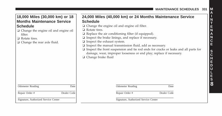
18,000 Miles (30,000 km) or 18Months Maintenance ServiceSchedule❏ Change the engine oil and engine oil
filter.❏ Rotate tires.❏ Change the rear axle fluid.
Odometer Reading Date
Repair Order # Dealer Code
Signature, Authorized Service Center
24,000 Miles (40,000 km) or 24 Months Maintenance ServiceSchedule❏ Change the engine oil and engine oil filter.❏ Rotate tires.❏ Replace the air conditioning filter (if equipped).❏ Inspect the brake linings, and replace if necessary.❏ Inspect the exhaust system.❏ Inspect the manual transmission fluid, add as necessary.❏ Inspect the front suspension and tie rod ends for cracks or leaks and all parts for
damage, wear, improper looseness or end play; replace if necessary.❏ Change brake fluid
Odometer Reading Date
Repair Order # Dealer Code
Signature, Authorized Service Center
8
MAINTENANCE
SCHEDULES
MAINTENANCE SCHEDULES 331
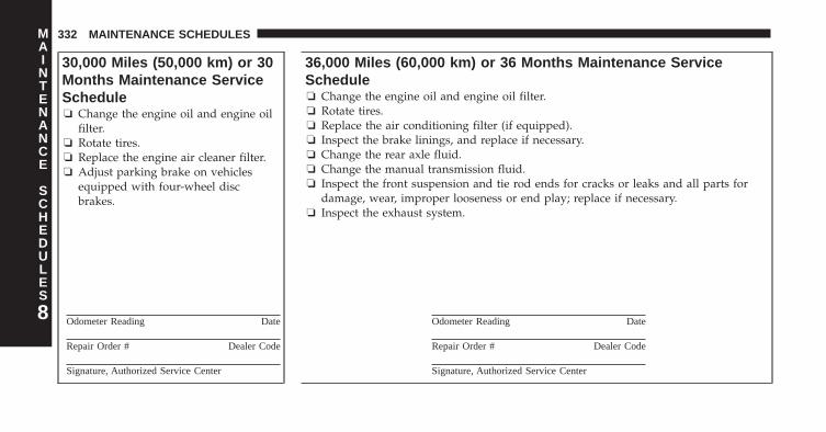
30,000 Miles (50,000 km) or 30Months Maintenance ServiceSchedule❏ Change the engine oil and engine oil
filter.❏ Rotate tires.❏ Replace the engine air cleaner filter.❏ Adjust parking brake on vehicles
equipped with four-wheel discbrakes.
Odometer Reading Date
Repair Order # Dealer Code
Signature, Authorized Service Center
36,000 Miles (60,000 km) or 36 Months Maintenance ServiceSchedule❏ Change the engine oil and engine oil filter.❏ Rotate tires.❏ Replace the air conditioning filter (if equipped).❏ Inspect the brake linings, and replace if necessary.❏ Change the rear axle fluid.❏ Change the manual transmission fluid.❏ Inspect the front suspension and tie rod ends for cracks or leaks and all parts for
damage, wear, improper looseness or end play; replace if necessary.❏ Inspect the exhaust system.
Odometer Reading Date
Repair Order # Dealer Code
Signature, Authorized Service Center
8
MAINTENANCE
SCHEDULES
332 MAINTENANCE SCHEDULES

42,000 Miles (70,000 km) or 42Months Maintenance ServiceSchedule❏ Change the engine oil and engine oil
filter.❏ Rotate tires.
Odometer Reading Date
Repair Order # Dealer Code
Signature, Authorized Service Center
48,000 Miles (80,000 km) or 48 Months Maintenance ServiceSchedule❏ Change the engine oil and engine oil filter.❏ Rotate tires.❏ Replace the air conditioning filter (if equipped).❏ Inspect the brake linings, and replace if necessary.❏ Inspect the exhaust system.❏ Inspect the front suspension and tie rod ends for cracks or leaks and all parts for
damage, wear, improper looseness or end play; replace if necessary.❏ Inspect the manual transmission fluid, add as necessary.❏ Change brake fluid
Odometer Reading Date
Repair Order # Dealer Code
Signature, Authorized Service Center
8
MAINTENANCE
SCHEDULES
MAINTENANCE SCHEDULES 333
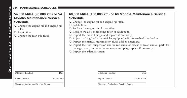
54,000 Miles (90,000 km) or 54Months Maintenance ServiceSchedule❏ Change the engine oil and engine oil
filter.❏ Rotate tires.❏ Change the rear axle fluid.
Odometer Reading Date
Repair Order # Dealer Code
Signature, Authorized Service Center
60,000 Miles (100,000 km) or 60 Months Maintenance ServiceSchedule❏ Change the engine oil and engine oil filter.❏ Rotate tires.❏ Replace the engine air cleaner filter.❏ Replace the air conditioning filter (if equipped).❏ Inspect the brake linings, and replace if necessary.❏ Adjust parking brake on vehicles equipped with four-wheel disc brakes.❏ Inspect the manual transmission fluid, add as necessary.❏ Inspect the front suspension and tie rod ends for cracks or leaks and all parts for
damage, wear, improper looseness or end play; replace if necessary.❏ Inspect the exhaust system.
Odometer Reading Date
Repair Order # Dealer Code
Signature, Authorized Service Center
8
MAINTENANCE
SCHEDULES
334 MAINTENANCE SCHEDULES
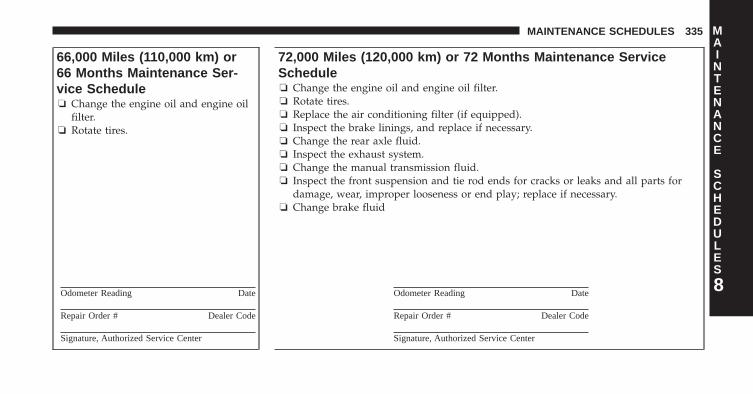
66,000 Miles (110,000 km) or66 Months Maintenance Ser-vice Schedule❏ Change the engine oil and engine oil
filter.❏ Rotate tires.
Odometer Reading Date
Repair Order # Dealer Code
Signature, Authorized Service Center
72,000 Miles (120,000 km) or 72 Months Maintenance ServiceSchedule❏ Change the engine oil and engine oil filter.❏ Rotate tires.❏ Replace the air conditioning filter (if equipped).❏ Inspect the brake linings, and replace if necessary.❏ Change the rear axle fluid.❏ Inspect the exhaust system.❏ Change the manual transmission fluid.❏ Inspect the front suspension and tie rod ends for cracks or leaks and all parts for
damage, wear, improper looseness or end play; replace if necessary.❏ Change brake fluid
Odometer Reading Date
Repair Order # Dealer Code
Signature, Authorized Service Center
8
MAINTENANCE
SCHEDULES
MAINTENANCE SCHEDULES 335
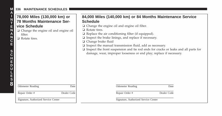
78,000 Miles (130,000 km) or78 Months Maintenance Ser-vice Schedule❏ Change the engine oil and engine oil
filter.❏ Rotate tires.
Odometer Reading Date
Repair Order # Dealer Code
Signature, Authorized Service Center
84,000 Miles (140,000 km) or 84 Months Maintenance ServiceSchedule❏ Change the engine oil and engine oil filter.❏ Rotate tires.❏ Replace the air conditioning filter (if equipped).❏ Inspect the brake linings, and replace if necessary.❏ Change brake fluid❏ Inspect the manual transmission fluid, add as necessary.❏ Inspect the front suspension and tie rod ends for cracks or leaks and all parts for
damage, wear, improper looseness or end play; replace if necessary.
Odometer Reading Date
Repair Order # Dealer Code
Signature, Authorized Service Center
8
MAINTENANCE
SCHEDULES
336 MAINTENANCE SCHEDULES
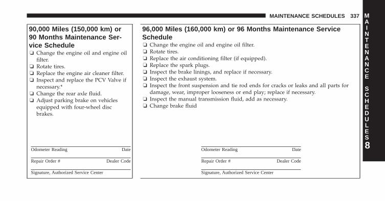
90,000 Miles (150,000 km) or90 Months Maintenance Ser-vice Schedule❏ Change the engine oil and engine oil
filter.❏ Rotate tires.❏ Replace the engine air cleaner filter.❏ Inspect and replace the PCV Valve if
necessary.*❏ Change the rear axle fluid.❏ Adjust parking brake on vehicles
equipped with four-wheel discbrakes.
Odometer Reading Date
Repair Order # Dealer Code
Signature, Authorized Service Center
96,000 Miles (160,000 km) or 96 Months Maintenance ServiceSchedule❏ Change the engine oil and engine oil filter.❏ Rotate tires.❏ Replace the air conditioning filter (if equipped).❏ Replace the spark plugs.❏ Inspect the brake linings, and replace if necessary.❏ Inspect the exhaust system.❏ Inspect the front suspension and tie rod ends for cracks or leaks and all parts for
damage, wear, improper looseness or end play; replace if necessary.❏ Inspect the manual transmission fluid, add as necessary.❏ Change brake fluid
Odometer Reading Date
Repair Order # Dealer Code
Signature, Authorized Service Center
8
MAINTENANCE
SCHEDULES
MAINTENANCE SCHEDULES 337
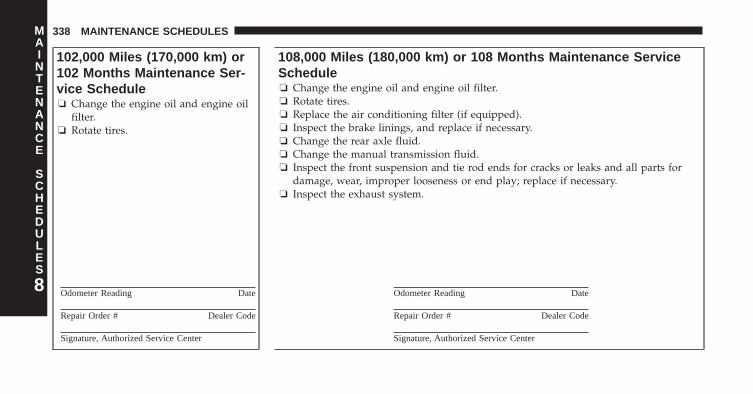
102,000 Miles (170,000 km) or102 Months Maintenance Ser-vice Schedule❏ Change the engine oil and engine oil
filter.❏ Rotate tires.
Odometer Reading Date
Repair Order # Dealer Code
Signature, Authorized Service Center
108,000 Miles (180,000 km) or 108 Months Maintenance ServiceSchedule❏ Change the engine oil and engine oil filter.❏ Rotate tires.❏ Replace the air conditioning filter (if equipped).❏ Inspect the brake linings, and replace if necessary.❏ Change the rear axle fluid.❏ Change the manual transmission fluid.❏ Inspect the front suspension and tie rod ends for cracks or leaks and all parts for
damage, wear, improper looseness or end play; replace if necessary.❏ Inspect the exhaust system.
Odometer Reading Date
Repair Order # Dealer Code
Signature, Authorized Service Center
8
MAINTENANCE
SCHEDULES
338 MAINTENANCE SCHEDULES
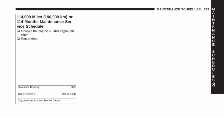
114,000 Miles (190,000 km) or114 Months Maintenance Ser-vice Schedule❏ Change the engine oil and engine oil
filter.❏ Rotate tires.
Odometer Reading Date
Repair Order # Dealer Code
Signature, Authorized Service Center
8
MAINTENANCE
SCHEDULES
MAINTENANCE SCHEDULES 339
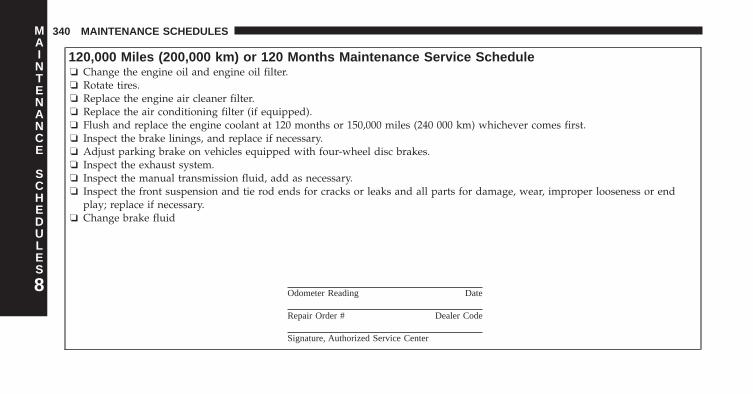
120,000 Miles (200,000 km) or 120 Months Maintenance Service Schedule❏ Change the engine oil and engine oil filter.❏ Rotate tires.❏ Replace the engine air cleaner filter.❏ Replace the air conditioning filter (if equipped).❏ Flush and replace the engine coolant at 120 months or 150,000 miles (240 000 km) whichever comes first.❏ Inspect the brake linings, and replace if necessary.❏ Adjust parking brake on vehicles equipped with four-wheel disc brakes.❏ Inspect the exhaust system.❏ Inspect the manual transmission fluid, add as necessary.❏ Inspect the front suspension and tie rod ends for cracks or leaks and all parts for damage, wear, improper looseness or end
play; replace if necessary.❏ Change brake fluid
Odometer Reading Date
Repair Order # Dealer Code
Signature, Authorized Service Center
8
MAINTENANCE
SCHEDULES
340 MAINTENANCE SCHEDULES

126,000 Miles (210,000 km) or126 Months Maintenance Ser-vice Schedule❏ Change the engine oil and engine oil
filter.❏ Rotate tires.❏ Change the rear axle fluid.
Odometer Reading Date
Repair Order # Dealer Code
Signature, Authorized Service Center
132,000 Miles (220,000 km) or 132 Months Maintenance ServiceSchedule❏ Change the engine oil and engine oil filter.❏ Rotate tires.❏ Replace the air conditioning filter (if equipped).❏ Inspect the brake linings, and replace if necessary.❏ Inspect the manual transmission fluid, add as necessary.❏ Inspect the front suspension and tie rod ends for cracks or leaks and all parts for
damage, wear, improper looseness or end play; replace if necessary.❏ Inspect the exhaust system.
Odometer Reading Date
Repair Order # Dealer Code
Signature, Authorized Service Center
8
MAINTENANCE
SCHEDULES
MAINTENANCE SCHEDULES 341
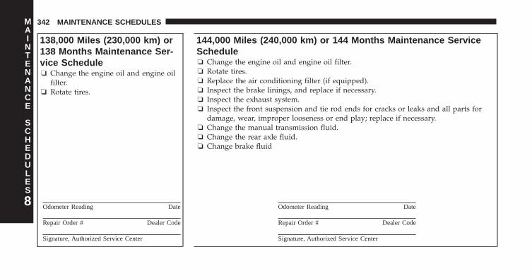
138,000 Miles (230,000 km) or138 Months Maintenance Ser-vice Schedule❏ Change the engine oil and engine oil
filter.❏ Rotate tires.
Odometer Reading Date
Repair Order # Dealer Code
Signature, Authorized Service Center
144,000 Miles (240,000 km) or 144 Months Maintenance ServiceSchedule❏ Change the engine oil and engine oil filter.❏ Rotate tires.❏ Replace the air conditioning filter (if equipped).❏ Inspect the brake linings, and replace if necessary.❏ Inspect the exhaust system.❏ Inspect the front suspension and tie rod ends for cracks or leaks and all parts for
damage, wear, improper looseness or end play; replace if necessary.❏ Change the manual transmission fluid.❏ Change the rear axle fluid.❏ Change brake fluid
Odometer Reading Date
Repair Order # Dealer Code
Signature, Authorized Service Center
8
MAINTENANCE
SCHEDULES
342 MAINTENANCE SCHEDULES
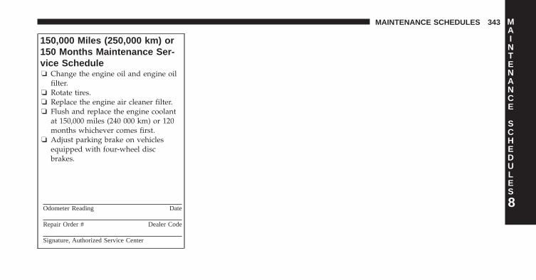
150,000 Miles (250,000 km) or150 Months Maintenance Ser-vice Schedule❏ Change the engine oil and engine oil
filter.❏ Rotate tires.❏ Replace the engine air cleaner filter.❏ Flush and replace the engine coolant
at 150,000 miles (240 000 km) or 120months whichever comes first.
❏ Adjust parking brake on vehiclesequipped with four-wheel discbrakes.
Odometer Reading Date
Repair Order # Dealer Code
Signature, Authorized Service Center
8
MAINTENANCE
SCHEDULES
MAINTENANCE SCHEDULES 343
* This maintenance is recommended by the manufacturerto the owner, but is not required to maintain emissionswarranty.
WARNING!
• You can be badly injured working on or around amotor vehicle. Do only service work for which youhave the knowledge and the right equipment. Ifyou have any doubt about your ability to perform aservice job, take your vehicle to a competent me-chanic.
• Failure to properly inspect and maintain your ve-hicle could result in a component malfunction andeffect vehicle handling and performance. Thiscould cause an accident.8
MAINTENANCE
SCHEDULES
344 MAINTENANCE SCHEDULES
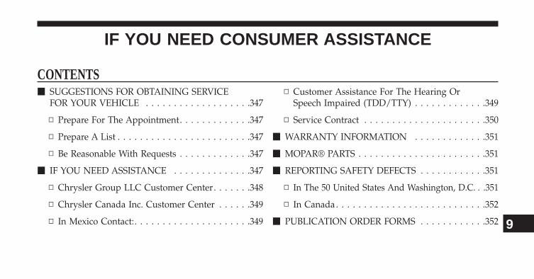
IF YOU NEED CONSUMER ASSISTANCE
CONTENTS� SUGGESTIONS FOR OBTAINING SERVICE
FOR YOUR VEHICLE . . . . . . . . . . . . . . . . . . .347
▫ Prepare For The Appointment. . . . . . . . . . . . .347
▫ Prepare A List . . . . . . . . . . . . . . . . . . . . . . . .347
▫ Be Reasonable With Requests . . . . . . . . . . . . .347
� IF YOU NEED ASSISTANCE . . . . . . . . . . . . . .347
▫ Chrysler Group LLC Customer Center. . . . . . .348
▫ Chrysler Canada Inc. Customer Center . . . . . .349
▫ In Mexico Contact:. . . . . . . . . . . . . . . . . . . . .349
▫ Customer Assistance For The Hearing OrSpeech Impaired (TDD/TTY) . . . . . . . . . . . . .349
▫ Service Contract . . . . . . . . . . . . . . . . . . . . . .350
� WARRANTY INFORMATION . . . . . . . . . . . . .351
� MOPAR® PARTS . . . . . . . . . . . . . . . . . . . . . . .351
� REPORTING SAFETY DEFECTS . . . . . . . . . . . .351
▫ In The 50 United States And Washington, D.C. . .351
▫ In Canada . . . . . . . . . . . . . . . . . . . . . . . . . . .352
� PUBLICATION ORDER FORMS . . . . . . . . . . . .352 9
� DEPARTMENT OF TRANSPORTATIONUNIFORM TIRE QUALITY GRADES . . . . . . . .353
▫ Treadwear. . . . . . . . . . . . . . . . . . . . . . . . . . .354
▫ Traction Grades . . . . . . . . . . . . . . . . . . . . . . .354
▫ Temperature Grades. . . . . . . . . . . . . . . . . . . .355
346 IF YOU NEED CONSUMER ASSISTANCE
SUGGESTIONS FOR OBTAINING SERVICE FORYOUR VEHICLE
Prepare For The Appointment
If you are having warranty work done, be sure to havethe right papers with you. Take your warranty folder. Allwork to be performed may not be covered by thewarranty. Discuss additional charges with the servicemanager. Keep a maintenance log of your vehicle’sservice history. This can often provide a clue to thecurrent problem.
Prepare A List
Make a written list of your vehicle’s problems or thespecific work you want done. If you’ve had an accidentor work done that is not on your maintenance log, let theservice advisor know.
Be Reasonable With Requests
If you list a number of items and you must have yourvehicle by the end of the day, discuss the situation withthe service advisor and list the items in order of priority.At many authorized dealer, you may obtain a rentalvehicle at a minimal daily charge. If you need a rental, itis advisable to make these arrangements when you callfor an appointment.
IF YOU NEED ASSISTANCE
The manufacturer and its authorized dealer are vitallyinterested in your satisfaction. We want you to be happywith our products and services.
9
IF YOU NEED CONSUMER ASSISTANCE 347
Warranty service must be done by an authorized dealer.We strongly recommend that you take the vehicle to anauthorized dealer. They know your vehicle the best, andare most concerned that you get prompt and high qualityservice. The manufacturer’s authorized dealer have thefacilities, factory-trained technicians, special tools, andthe latest information to ensure the vehicle is fixedcorrectly and in a timely manner.
This is why you should always talk to an authorizeddealer service manager first. Most matters can be re-solved with this process.
• If for some reason you are still not satisfied, talk to thegeneral manager or owner of the authorized dealer.They want to know if you need assistance.
• If an authorized dealer is unable to resolve the con-cern, you may contact the manufacturer’s customercenter.
Any communication to the manufacturer’s customer cen-ter should include the following information:
• Owner’s name and address
• Owner’s telephone number (home and office)
• Authorized dealer name
• Vehicle Identification Number (VIN)
• Vehicle delivery date and mileage
Chrysler Group LLC Customer Center
P.O. Box 21–8004
Auburn Hills, MI 48321–8004
Phone: (855) SRT–TEAM
348 IF YOU NEED CONSUMER ASSISTANCE
Chrysler Canada Inc. Customer Center
P.O. Box 1621
Windsor, Ontario N9A 4H6
Phone: (800) 465–2001 English / (800) 387–9983 French
In Mexico Contact:
Av. Prolongacion Paseo de la Reforma, 1240
Sante Fe C.P. 05109
Mexico, D. F.
In Mexico City: 5081-7568
Outside Mexico City: 1-800-505-1300
Customer Assistance For The Hearing Or SpeechImpaired (TDD/TTY)
To assist customers who have hearing difficulties, themanufacturer has installed special TDD (Telecommuni-cation Devices for the Deaf) equipment at its customercenter. Any hearing or speech impaired customer, whohas access to a TDD or a conventional teletypewriter(TTY) in the United States, can communicate with themanufacturer by dialing 1–800–380–CHRY.
Canadian residents with hearing difficulties that requireassistance can use the special needs relay service offeredby Bell Canada. For TTY teletypewriter users, dial 711and for Voice callers, dial 1 800 855-0511 to connect witha Bell Relay Service operator.
9
IF YOU NEED CONSUMER ASSISTANCE 349
Service Contract
You may have purchased a service contract for a vehicleto help protect you from the high cost of unexpectedrepairs after the manufacturer’s New Vehicle LimitedWarranty expires. The manufacturer stands behind onlythe manufacturer’s service contracts. If you purchased amanufacturer’s service contract, you will receive PlanProvisions and an Owner Identification Card in the mailwithin three weeks of the vehicle delivery date. If youhave any questions about the service contract, call themanufacturer’s Service Contract National CustomerHotline at 1-800-521-9922 (Canadian residents, call (800)465–2001 English / (800) 387–9983 French).
The manufacturer will not stand behind any servicecontract that is not the manufacturer’s service contract. Itis not responsible for any service contract other than themanufacturer’s service contract. If you purchased a ser-vice contract that is not a manufacturer’s service contract,and you require service after the manufacturer’s New
Vehicle Limited Warranty expires, please refer to thecontract documents, and contact the person listed inthose documents.
We appreciate that you have made a major investmentwhen you purchased the vehicle. An authorized dealerhas also made a major investment in facilities, tools, andtraining to assure that you are absolutely delighted withthe ownership experience. You will be pleased with theirsincere efforts to resolve any warranty issues or relatedconcerns.
WARNING!
Engine exhaust, some of its constituents, and certainvehicle components contain, or emit, chemicalsknown to the State of California to cause cancer andbirth defects, or other reproductive harm. In addi-tion, certain fluids contained in vehicles and certain
(Continued)
350 IF YOU NEED CONSUMER ASSISTANCE
WARNING! (Continued)products of component wear contain, or emit, chemi-cals known to the State of California to cause cancerand birth defects, or other reproductive harm.
WARRANTY INFORMATION
See the Warranty Information Booklet, located on theDVD, for the terms and provisions of Chrysler GroupLLC warranties applicable to this vehicle and market.
MOPAR® PARTS
MOPAR® fluids, lubricants, parts, and accessories areavailable from an authorized dealer. They are recom-mended for your vehicle in order to help keep the vehicleoperating at its best.
REPORTING SAFETY DEFECTS
In The 50 United States And Washington, D.C.
If you believe that your vehicle has a defect that couldcause a crash or cause injury or death, you shouldimmediately inform the National Highway Traffic SafetyAdministration (NHTSA) in addition to notifying themanufacturer.
If NHTSA receives similar complaints, it may open aninvestigation, and if it finds that a safety defect exists ina group of vehicles, it may order a recall and remedycampaign. However, NHTSA cannot become involved inindividual problems between you, your authorizeddealer, and the manufacturer.
9
IF YOU NEED CONSUMER ASSISTANCE 351

To contact NHTSA, you may either call the Auto SafetyHotline toll free at 1–888–327–4236 (TTY: 1–800–424–9153), or go to http://www.safercar.gov; or write to:Administrator, NHTSA, 1200 New Jersey Avenue, SE.,West Building, Washington, D.C. 20590. You can alsoobtain other information about motor vehicle safety fromhttp://www.safercar.gov.
In Canada
If you believe that your vehicle has a safety defect, youshould contact the Customer Service Department immedi-ately. Canadian customers who wish to report a safety defectto the Canadian government should contact TransportCanada, Motor Vehicle Defect Investigations and Recalls at1-800-333-0510 or go to http://www.tc.gc.ca/roadsafety/
PUBLICATION ORDER FORMS
To order the following manuals, you may use either thewebsite or the phone numbers listed below. Visa, Mas-tercard, American Express, and Discover orders are ac-cepted. If you prefer mailing your payment, please callfor an order form.
NOTE: A street address is required when orderingmanuals (no P.O. Boxes).
Service Manuals
These comprehensive Service Manuals provide the infor-mation that students and professional technicians need indiagnosing/troubleshooting, problem solving, maintain-ing, servicing, and repairing Chrysler Group LLC ve-hicles. A complete working knowledge of the vehicle,system, and/or components is written in straightforwardlanguage with illustrations, diagrams, and charts.
352 IF YOU NEED CONSUMER ASSISTANCE
Diagnostic Procedure Manuals
Diagnostic Procedure Manuals are filled with diagrams,charts and detailed illustrations. These practical manualsmake it easy for students and technicians to find and fixproblems on computer-controlled vehicle systems andfeatures. They show exactly how to find and correctproblems the first time, using step-by-step troubleshoot-ing and drivability procedures, proven diagnostic testsand a complete list of all tools and equipment.
Owner’s Manuals
These Owner’s Manuals have been prepared with theassistance of service and engineering specialists to ac-quaint you with specific Chrysler Group LLC vehicles.Included are starting, operating, emergency and mainte-nance procedures as well as specifications, capabilitiesand safety tips.
Call toll free at:
• 1–800–890–4038 (U.S.)
• 1–800–387–1143 (Canada)
Or
Visit us on the Worldwide Web at:
• www.techauthority.com
DEPARTMENT OF TRANSPORTATION UNIFORMTIRE QUALITY GRADES
The following tire grading categories were established bythe National Highway Traffic Safety Administration. Thespecific grade rating assigned by the tire’s manufacturerin each category is shown on the sidewall of the tires onyour vehicle.
All passenger car tires must conform to Federal safetyrequirements in addition to these grades.
9
IF YOU NEED CONSUMER ASSISTANCE 353
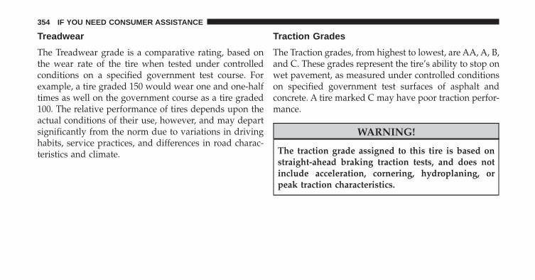
Treadwear
The Treadwear grade is a comparative rating, based onthe wear rate of the tire when tested under controlledconditions on a specified government test course. Forexample, a tire graded 150 would wear one and one-halftimes as well on the government course as a tire graded100. The relative performance of tires depends upon theactual conditions of their use, however, and may departsignificantly from the norm due to variations in drivinghabits, service practices, and differences in road charac-teristics and climate.
Traction Grades
The Traction grades, from highest to lowest, are AA, A, B,and C. These grades represent the tire’s ability to stop onwet pavement, as measured under controlled conditionson specified government test surfaces of asphalt andconcrete. A tire marked C may have poor traction perfor-mance.
WARNING!
The traction grade assigned to this tire is based onstraight-ahead braking traction tests, and does notinclude acceleration, cornering, hydroplaning, orpeak traction characteristics.
354 IF YOU NEED CONSUMER ASSISTANCE
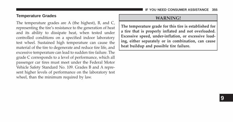
Temperature Grades
The temperature grades are A (the highest), B, and C,representing the tire’s resistance to the generation of heatand its ability to dissipate heat, when tested undercontrolled conditions on a specified indoor laboratorytest wheel. Sustained high temperature can cause thematerial of the tire to degenerate and reduce tire life, andexcessive temperature can lead to sudden tire failure. Thegrade C corresponds to a level of performance, which allpassenger car tires must meet under the Federal MotorVehicle Safety Standard No. 109. Grades B and A repre-sent higher levels of performance on the laboratory testwheel, than the minimum required by law.
WARNING!
The temperature grade for this tire is established fora tire that is properly inflated and not overloaded.Excessive speed, under-inflation, or excessive load-ing, either separately or in combination, can causeheat buildup and possible tire failure.
9
IF YOU NEED CONSUMER ASSISTANCE 355


INDEX
10
About Your Brakes . . . . . . . . . . . . . . . . . . . . . . . .208ABS (Anti-Lock Brake System) . . . . . . . . . . . . . . . .210Adding Engine Coolant (Antifreeze) . . . . . . . . . . . .298Adding Fuel . . . . . . . . . . . . . . . . . . . . . . . . . . . . .251Adding Washer Fluid . . . . . . . . . . . . . . . . . . . . . .293Additives, Fuel . . . . . . . . . . . . . . . . . . . . . . . . . . .250Adjustable Pedals . . . . . . . . . . . . . . . . . . . . . . . . .108Airbag. . . . . . . . . . . . . . . . . . . . . . . . . . . . . . . . . .46Airbag Deployment . . . . . . . . . . . . . . . . . . . . . . . .51Airbag Light . . . . . . . . . . . . . . . . . . . . . . . . . . . . .51Airbag Maintenance . . . . . . . . . . . . . . . . . . . . . . . .66Air Cleaner, Engine (Engine Air Cleaner Filter) . . . .286Air Conditioner Maintenance . . . . . . . . . . . . . . . . .290Air Conditioning, Operating Tips . . . . . . . . . . . . . .185Air Conditioning Refrigerant . . . . . . . . . . . . . . . . .290Air Conditioning System . . . . . . . . . . . . . . . . . . . .290Air Pressure, Tires. . . . . . . . . . . . . . . . . . . . . . . . .230Alarm Light . . . . . . . . . . . . . . . . . . . . . . . . . . . . .141Alarm System (Security Alarm) . . . . . . . . . . . . . . . .18
Alterations/Modifications, Vehicle . . . . . . . . . . . . . . .7Antenna. . . . . . . . . . . . . . . . . . . . . . . . . . . . . . . .177Antifreeze (Engine Coolant) . . . . . . . . . . . . . . . . . .297
Capacities . . . . . . . . . . . . . . . . . . . . . . . . . . . .324Disposal . . . . . . . . . . . . . . . . . . . . . . . . . . . . . .300
Anti-Lock Brake System (ABS) . . . . . . . . . . . . . . . .210Anti-Lock Warning Light . . . . . . . . . . . . . . . . . . . .147Anti-Theft Security Alarm (Theft Alarm) . . . . . . . . . .18Appearance Care . . . . . . . . . . . . . . . . . . . . . . . . .306Auto Down Power Windows . . . . . . . . . . . . . . . . . .31Automatic Door Locks . . . . . . . . . . . . . . . . . . . . . .29Automatic Headlights . . . . . . . . . . . . . . . . . . . . . . .99Auto Unlock, Doors . . . . . . . . . . . . . . . . . . . . . . . .29Auto Up Power Windows . . . . . . . . . . . . . . . . . . . .31Auxiliary Electrical Outlet (Power Outlet) . . . . . . . .124Auxiliary Power Outlet . . . . . . . . . . . . . . . . . . . . .124
Battery . . . . . . . . . . . . . . . . . . . . . . . . . . . . . . . . .287Emergency Starting . . . . . . . . . . . . . . . . . . . . . .272
358 INDEX
Jump Starting . . . . . . . . . . . . . . . . . . . . . . . . . .272Keyless Transmitter Replacement (RKE) . . . . . . . .23Location . . . . . . . . . . . . . . . . . . . . . . . . . . . . . .287Saving Feature (Protection) . . . . . . . . . . . . . . . .289Storing Vehicle . . . . . . . . . . . . . . . . . . . . . . . . .289
Belts, Seat . . . . . . . . . . . . . . . . . . . . . . . . . . . . . . .34Bladder . . . . . . . . . . . . . . . . . . . . . . . . . . . . . . . . .57Body Mechanism Lubrication . . . . . . . . . . . . . . . . .291B-Pillar Location . . . . . . . . . . . . . . . . . . . . . . . . . .224Brake Control System, Electronic . . . . . . . . . . . . . .212Brake, Parking . . . . . . . . . . . . . . . . . . . . . . . . . . .206Brake System . . . . . . . . . . . . . . . . . . . . . . . . . . . .208
Anti-Lock (ABS) . . . . . . . . . . . . . . . . . . . . . . . .208Fluid Check . . . . . . . . . . . . . . . . . . . . . . . . . . .302Master Cylinder . . . . . . . . . . . . . . . . . . . . . . . .302Warning Light . . . . . . . . . . . . . . . . . . . . . . . . .139
Break-In Recommendations, New Vehicle . . . . . . . . .78Brightness, Interior Lights . . . . . . . . . . . . . . . . . . .103Bulb Replacement . . . . . . . . . . . . . . . . . . . . . . . . .323
Bulbs, Light . . . . . . . . . . . . . . . . . . . . . . . . . . . . . .81
Camera, Rear . . . . . . . . . . . . . . . . . . . . . . . . . . . .114Capacities, Antifreeze (Engine Coolant) . . . . . . . . . .324Capacities, Fluid . . . . . . . . . . . . . . . . . . . . . . . . . .324Caps, Filler
Oil (Engine) . . . . . . . . . . . . . . . . . . . . . . . . . . .285Power Steering . . . . . . . . . . . . . . . . . . . . . . . . .205Radiator (Coolant Pressure) . . . . . . . . . . . . . . . .299
Carbon Monoxide Warning . . . . . . . . . . . . . . . . . . .79Car Washes . . . . . . . . . . . . . . . . . . . . . . . . . . . . .306Cellular Phone . . . . . . . . . . . . . . . . . . . . . . . . . . .177Chains, Tire . . . . . . . . . . . . . . . . . . . . . . . . . . . . .240Chart, Tire Sizing . . . . . . . . . . . . . . . . . . . . . . . . .218Check Engine Light (Malfunction Indicator Light) . .143Checking Your Vehicle For Safety . . . . . . . . . . . . . . .78Checks, Safety . . . . . . . . . . . . . . . . . . . . . . . . . . . .78Child Restraint . . . . . . . . . . . . . . . . . . . . . . . . . . . .68Child Restraint Tether Anchors . . . . . . . . . . . . . . . .75 10
INDEX 359

Clean Air Gasoline . . . . . . . . . . . . . . . . . . . . . . . .248Cleaning
Wheels . . . . . . . . . . . . . . . . . . . . . . . . . . . . . . .307Windshield Wiper Blades . . . . . . . . . . . . . . . . . .292
Climate Control . . . . . . . . . . . . . . . . . . . . . . . . . .177Clutch Fluid . . . . . . . . . . . . . . . . . . . . . . . . . . . . .305Compact Spare Tire . . . . . . . . . . . . . . . . . . . . . . . .235Contract, Service . . . . . . . . . . . . . . . . . . . . . . . . . .350Coolant Pressure Cap (Radiator Cap) . . . . . . . . . . .299Cooling System. . . . . . . . . . . . . . . . . . . . . . . . . . .296
Adding Coolant (Antifreeze) . . . . . . . . . . . . . . .298Coolant Capacity . . . . . . . . . . . . . . . . . . . . . . .324Coolant Level . . . . . . . . . . . . . . . . . . . . . . . . . .296Disposal of Used Coolant . . . . . . . . . . . . . . . . .300Drain, Flush, and Refill . . . . . . . . . . . . . . . . . . .297Inspection . . . . . . . . . . . . . . . . . . . . . . . . . . . .300Points to Remember . . . . . . . . . . . . . . . . . . . . .300Pressure Cap . . . . . . . . . . . . . . . . . . . . . . . . . .299Radiator Cap . . . . . . . . . . . . . . . . . . . . . . . . . .299
Selection of Coolant (Antifreeze) . . . . . . . . . . . . .297Corrosion Protection . . . . . . . . . . . . . . . . . . . . . . .306Cruise Light . . . . . . . . . . . . . . . . . . . . . . . . . . . . .144Cupholders . . . . . . . . . . . . . . . . . . . . . . . . . . . . .127Customer Assistance . . . . . . . . . . . . . . . . . . . . . . .347
Data Recorder, Event . . . . . . . . . . . . . . . . . . . . . . .67Daytime Brightness, Interior Lights. . . . . . . . . . . . .104Daytime Running Lights . . . . . . . . . . . . . . . . . . . .101Dealer Service. . . . . . . . . . . . . . . . . . . . . . . . . . . .282Defroster, Rear Window. . . . . . . . . . . . . . . . . . . . .131Defroster, Windshield . . . . . . . . . . . . . . . . . . . . . . .80Delay (Intermittent) Wipers . . . . . . . . . . . . . . . . . .105Diagnostic System, Onboard . . . . . . . . . . . . . . . . .280Dimmer Switch, Headlight. . . . . . . . . . . . . . . . . . .102Dipsticks
Power Steering . . . . . . . . . . . . . . . . . . . . . . . . .205Disposal
Antifreeze (Engine Coolant) . . . . . . . . . . . . . . . .300
360 INDEX
Door Locks . . . . . . . . . . . . . . . . . . . . . . . . . . . . . .27Door Locks, Automatic . . . . . . . . . . . . . . . . . . . . . .29Door Opener, Garage. . . . . . . . . . . . . . . . . . . . . . .116Doors . . . . . . . . . . . . . . . . . . . . . . . . . . . . . . . . . .27Driving
Through Flowing, Rising, or Shallow StandingWater . . . . . . . . . . . . . . . . . . . . . . . . . . . . . . . .202
Electrical Outlet, Auxiliary (Power Outlet) . . . . . . . .124Electric Remote Mirrors. . . . . . . . . . . . . . . . . . . . . .88Electronic Brake Control System . . . . . . . . . . . . . . .212
Traction Control System . . . . . . . . . . . . . . . . . . .213Electronic Speed Control (Cruise Control) . . . . . . . .110Electronic Stability Control (ESC) . . . . . . . . . . . . . .213Electronic Vehicle Information Center (EVIC) . . . . . .114Emergency Brake . . . . . . . . . . . . . . . . . . . . . . . . .206Emergency, In Case of
Freeing Vehicle When Stuck . . . . . . . . . . . . . . . .275Hazard Warning Flasher . . . . . . . . . . . . . . . . . .260
Jump Starting . . . . . . . . . . . . . . . . . . . . . . . . . .272Overheating . . . . . . . . . . . . . . . . . . . . . . . . . . .260Towing . . . . . . . . . . . . . . . . . . . . . . . . . . . . . .276
Emission Control System Maintenance . . . . . . . . . .280Engine . . . . . . . . . . . . . . . . . . . . . . . . . . . . . . . . .279
Air Cleaner . . . . . . . . . . . . . . . . . . . . . . . . . . .286Break-In Recommendations . . . . . . . . . . . . . . . . .78Checking Oil Level . . . . . . . . . . . . . . . . . . . . . .284Compartment . . . . . . . . . . . . . . . . . . . . . . . . . .279Coolant (Antifreeze) . . . . . . . . . . . . . . . . . . . . .296Cooling . . . . . . . . . . . . . . . . . . . . . . . . . . . . . .296Exhaust Gas Caution . . . . . . . . . . . . . . . . . . . . .34Fails to Start . . . . . . . . . . . . . . . . . . . . . . . . . . .192Flooded, Starting . . . . . . . . . . . . . . . . . . . . . . .192Fuel Requirements . . . . . . . . . . . . . . . . . . . . . .247Oil . . . . . . . . . . . . . . . . . . . . . . . . . . . . . . . . . .284Oil Change Interval . . . . . . . . . . . . . . . . . . . . . .284Oil Filler Cap . . . . . . . . . . . . . . . . . . . . . . . . . .285Oil Selection . . . . . . . . . . . . . . . . . . . . . . . . . . .284 10
INDEX 361
Overheating . . . . . . . . . . . . . . . . . . . . . . . . . . .260Engine Oil Viscosity . . . . . . . . . . . . . . . . . . . . . . .285Enhanced Accident Response Feature . . . . . . . . . . . .64Ethanol . . . . . . . . . . . . . . . . . . . . . . . . . . . . . . . .248Event Data Recorder . . . . . . . . . . . . . . . . . . . . . . . .67Exhaust Gas Caution. . . . . . . . . . . . . . . . . . . . . . . .34Exhaust System . . . . . . . . . . . . . . . . . . . . . . . . . . .79Exterior Lighting . . . . . . . . . . . . . . . . . . . . . . . . . .98Exterior Lights . . . . . . . . . . . . . . . . . . . . . . . . . . . .81
Filler Location Fuel . . . . . . . . . . . . . . . . . . . . . . . .141Filters
Air Cleaner . . . . . . . . . . . . . . . . . . . . . . . . . . .286Engine Oil . . . . . . . . . . . . . . . . . . . . . . . . . . . .286Engine Oil Disposal . . . . . . . . . . . . . . . . . . . . .285
FlashersHazard Warning . . . . . . . . . . . . . . . . . . . . . . . .260Turn Signal . . . . . . . . . . . . . . . . . . . . . . . . . . . .81
Flash-To-Pass . . . . . . . . . . . . . . . . . . . . . . . . . . . .102
Flooded Engine Starting . . . . . . . . . . . . . . . . . . . .192Fluid Capacities . . . . . . . . . . . . . . . . . . . . . . . . . .324Fluid Leaks . . . . . . . . . . . . . . . . . . . . . . . . . . . . . .81Fluid Level Checks
Brake . . . . . . . . . . . . . . . . . . . . . . . . . . . . . . . .302Capacities . . . . . . . . . . . . . . . . . . . . . . . . . . . .324Clutch Fluid . . . . . . . . . . . . . . . . . . . . . . . . . . .305Cooling System . . . . . . . . . . . . . . . . . . . . . . . . .296Engine Oil . . . . . . . . . . . . . . . . . . . . . . . . . . . .284Manual Transmission . . . . . . . . . . . . . . . . . . . .304Power Steering . . . . . . . . . . . . . . . . . . . . . . . . .205
Fluids, Lubricants and Genuine Parts . . . . . . . . . . .325Four-Way Hazard Flasher . . . . . . . . . . . . . . . . . . .260Freeing A Stuck Vehicle . . . . . . . . . . . . . . . . . . . . .275Fuel . . . . . . . . . . . . . . . . . . . . . . . . . . . . . . . . . . .247
Additives . . . . . . . . . . . . . . . . . . . . . . . . . . . . .250Clean Air . . . . . . . . . . . . . . . . . . . . . . . . . . . . .248Ethanol . . . . . . . . . . . . . . . . . . . . . . . . . . . . . .248Filler Door (Gas Cap) . . . . . . . . . . . . . . . . . . . .141
362 INDEX
Gasoline . . . . . . . . . . . . . . . . . . . . . . . . . . . . . .247Gauge . . . . . . . . . . . . . . . . . . . . . . . . . . . . . . .141Materials Added . . . . . . . . . . . . . . . . . . . . . . . .250Methanol . . . . . . . . . . . . . . . . . . . . . . . . . . . . .248Octane Rating . . . . . . . . . . . . . . . . . . . . . . . . . .247Requirements . . . . . . . . . . . . . . . . . . . . . . . . . .247Tank Capacity . . . . . . . . . . . . . . . . . . . . . . . . . .324
Fuses . . . . . . . . . . . . . . . . . . . . . . . . . . . . . . . . . .311
Garage Door Opener (HomeLink®). . . . . . . . . . . . .116Gasoline, Clean Air . . . . . . . . . . . . . . . . . . . . . . . .248Gasoline (Fuel) . . . . . . . . . . . . . . . . . . . . . . . . . . .247Gasoline, Reformulated . . . . . . . . . . . . . . . . . . . . .248Gauges
Fuel . . . . . . . . . . . . . . . . . . . . . . . . . . . . . . . . .141Speedometer . . . . . . . . . . . . . . . . . . . . . . . . . .137Tachometer . . . . . . . . . . . . . . . . . . . . . . . . . . . .140
General Information . . . . . . . . . . . . . . . . . . . . . . . .18Glass Cleaning . . . . . . . . . . . . . . . . . . . . . . . . . . .309
Ground Clearance . . . . . . . . . . . . . . . . . . . . . . . . .257
HazardDriving Through Flowing, Rising, or ShallowStanding Water . . . . . . . . . . . . . . . . . . . . . . . . .202
Hazard Warning Flasher . . . . . . . . . . . . . . . . . . . .260Headlights
Automatic . . . . . . . . . . . . . . . . . . . . . . . . . . . . .99Delay . . . . . . . . . . . . . . . . . . . . . . . . . . . . . . . .100High Beam/Low Beam Select Switch . . . . . . . . .102Lights On Reminder . . . . . . . . . . . . . . . . . . . . .101On With Wipers . . . . . . . . . . . . . . . . . . . . . . . .100Passing . . . . . . . . . . . . . . . . . . . . . . . . . . . . . .102Switch . . . . . . . . . . . . . . . . . . . . . . . . . . . . . . . .98Time Delay . . . . . . . . . . . . . . . . . . . . . . . . . . . .100
Head Restraints . . . . . . . . . . . . . . . . . . . . . . . . . . .96High Beam/Low Beam Select (Dimmer) Switch . . . .102Holder, Cup . . . . . . . . . . . . . . . . . . . . . . . . . . . . .127HomeLink® (Garage Door Opener). . . . . . . . . . . . .116 10
INDEX 363
Hood Release . . . . . . . . . . . . . . . . . . . . . . . . . . . . .96Hydraulic Clutch Fluid . . . . . . . . . . . . . . . . . . . . .305
Illuminated Entry . . . . . . . . . . . . . . . . . . . . . . . . . .20Immobilizer (Sentry Key) . . . . . . . . . . . . . . . . . . . .16Infant Restraint . . . . . . . . . . . . . . . . . . . . . . . . . . .68Inside Rearview Mirror . . . . . . . . . . . . . . . . . . . . . .86Instrument Cluster . . . . . . . . . . . . . . . . . . . . . . . .137Instrument Panel and Controls . . . . . . . . . . . . . . . .135Instrument Panel Lens Cleaning . . . . . . . . . . . . . . .309Interior Appearance Care . . . . . . . . . . . . . . . . . . . .308Interior Lights . . . . . . . . . . . . . . . . . . . . . . . . . . .103Intermittent Wipers (Delay Wipers). . . . . . . . . . . . .105Introduction . . . . . . . . . . . . . . . . . . . . . . . . . . . . . .4
Jump Starting . . . . . . . . . . . . . . . . . . . . . . . . . . . .272
Key Fob. . . . . . . . . . . . . . . . . . . . . . . . . . . . . . . . .12Key-In Reminder . . . . . . . . . . . . . . . . . . . . . . . . . .15
Keyless Entry System . . . . . . . . . . . . . . . . . . . . . . .12Keyless Go. . . . . . . . . . . . . . . . . . . . . . . . . . . . . . .12Key, Programming . . . . . . . . . . . . . . . . . . . . . . . . .18Key, Replacement . . . . . . . . . . . . . . . . . . . . . . . . . .17Key, Sentry (Immobilizer) . . . . . . . . . . . . . . . . . . . .16Knee Bolster. . . . . . . . . . . . . . . . . . . . . . . . . . . . . .46
Lane Change and Turn Signals . . . . . . . . . . . . . . . .102Lap/Shoulder Belts. . . . . . . . . . . . . . . . . . . . . . . . .36Latches . . . . . . . . . . . . . . . . . . . . . . . . . . . . . . . . .81
Hood . . . . . . . . . . . . . . . . . . . . . . . . . . . . . . . .96Latch Plate. . . . . . . . . . . . . . . . . . . . . . . . . . . . . . .39Lead Free Gasoline . . . . . . . . . . . . . . . . . . . . . . . .247Leaks, Fluid . . . . . . . . . . . . . . . . . . . . . . . . . . . . . .81Life of Tires . . . . . . . . . . . . . . . . . . . . . . . . . . . . .238Liftgate . . . . . . . . . . . . . . . . . . . . . . . . . . . . . . . . .32Light Bulbs . . . . . . . . . . . . . . . . . . . . . . . . . . . . . .81Lights . . . . . . . . . . . . . . . . . . . . . . . . . . . . . . . . . .81
Airbag . . . . . . . . . . . . . . . . . . . . . . . . . . . . . . . .67
364 INDEX
Alarm . . . . . . . . . . . . . . . . . . . . . . . . . . . . . . .141Anti-Lock . . . . . . . . . . . . . . . . . . . . . . . . . . . . .147Automatic Headlights . . . . . . . . . . . . . . . . . . . . .99Brake Warning . . . . . . . . . . . . . . . . . . . . . . . . .139Bulb Replacement . . . . . . . . . . . . . . . . . . . . . . .322Cruise . . . . . . . . . . . . . . . . . . . . . . . . . . . . . . .144Daytime Running . . . . . . . . . . . . . . . . . . . . . . .101Dimmer Switch, Headlight . . . . . . . . . . . . . . . . .101Exterior . . . . . . . . . . . . . . . . . . . . . . . . . . . . . . .81Hazard Warning Flasher . . . . . . . . . . . . . . . . . .260Headlights . . . . . . . . . . . . . . . . . . . . . . . . . . . . .98Headlights On Reminder . . . . . . . . . . . . . . . . . .101Headlights On With Wipers . . . . . . . . . . . . . . . .100Headlight Switch . . . . . . . . . . . . . . . . . . . . . . . .98High Beam . . . . . . . . . . . . . . . . . . . . . . . . . . . .102High Beam Indicator . . . . . . . . . . . . . . . . . . . . .141High Beam/Low Beam Select . . . . . . . . . . . . . . .102Illuminated Entry . . . . . . . . . . . . . . . . . . . . . . . .20Instrument Cluster . . . . . . . . . . . . . . . . . . . . . . .98
Intensity Control . . . . . . . . . . . . . . . . . . . . . . . .103Interior . . . . . . . . . . . . . . . . . . . . . . . . . . . . . .103Lights On Reminder . . . . . . . . . . . . . . . . . . . . .101Malfunction Indicator (Check Engine) . . . . . . . . .143Oil Pressure . . . . . . . . . . . . . . . . . . . . . . . . . . .141Parade Mode (Daytime Brightness) . . . . . . . . . . .104Passing . . . . . . . . . . . . . . . . . . . . . . . . . . . . . .102Seat Belt Reminder . . . . . . . . . . . . . . . . . . . . . .137Security Alarm (Theft Alarm) . . . . . . . . . . . . . . .141Service . . . . . . . . . . . . . . . . . . . . . . . . . . . . . . .322Service Engine Soon (Malfunction Indicator) . . . .143Theft Alarm (Security Alarm) . . . . . . . . . . . . . . .141Tire Pressure Monitoring (TPMS) . . . . . . . . . . . .142Turn Signal . . . . . . . . . . . . . . . . . . . . . . . . . . . .81Vanity Mirror . . . . . . . . . . . . . . . . . . . . . . . . . . .89Warning (Instrument Cluster Description) . . . . . .137
Loading VehicleTires . . . . . . . . . . . . . . . . . . . . . . . . . . . . . . . .224
Locks . . . . . . . . . . . . . . . . . . . . . . . . . . . . . . . . . .27 10
INDEX 365
Automatic Door . . . . . . . . . . . . . . . . . . . . . . . . .29Auto Unlock . . . . . . . . . . . . . . . . . . . . . . . . . . .29Door . . . . . . . . . . . . . . . . . . . . . . . . . . . . . . . . .27Power Door . . . . . . . . . . . . . . . . . . . . . . . . . . . .27
Low Tire Indicator . . . . . . . . . . . . . . . . . . . . . . . .242Low Tire Pressure System . . . . . . . . . . . . . . . . . . .242Lubrication, Body . . . . . . . . . . . . . . . . . . . . . . . . .291
Maintenance Free Battery. . . . . . . . . . . . . . . . . . . .287Maintenance Procedures . . . . . . . . . . . . . . . . . . . .283Maintenance Schedule . . . . . . . . . . . . . . . . . . . . . .328Malfunction Indicator Light (Check Engine). . . . . . .143Manual, Service . . . . . . . . . . . . . . . . . . . . . . . . . .352Manual Transmission . . . . . . . . . . . . . . . . . . . . . .194
Fluid Level Check . . . . . . . . . . . . . . . . . . . . . . .304Lubricant Selection . . . . . . . . . . . . . . . . . . . . . .326Shift Speeds . . . . . . . . . . . . . . . . . . . . . . . . . . .197
Methanol . . . . . . . . . . . . . . . . . . . . . . . . . . . . . . .248Mirrors . . . . . . . . . . . . . . . . . . . . . . . . . . . . . . . . .86
Electric Remote . . . . . . . . . . . . . . . . . . . . . . . . .88Outside . . . . . . . . . . . . . . . . . . . . . . . . . . . . . . .88Rearview . . . . . . . . . . . . . . . . . . . . . . . . . . . . . .86Vanity . . . . . . . . . . . . . . . . . . . . . . . . . . . . . . . .89
Modifications/Alterations, Vehicle . . . . . . . . . . . . . . .7Monitor, Tire Pressure System . . . . . . . . . . . . . . . .242Mopar Parts . . . . . . . . . . . . . . . . . . . . . . . . . . . . .282MTBE/ETBE . . . . . . . . . . . . . . . . . . . . . . . . . . . .248Multi-Function Control Lever . . . . . . . . . . . . . . . . .101
New Vehicle Break-In Period . . . . . . . . . . . . . . . . . .78
Occupant Restraints . . . . . . . . . . . . . . . . . . . . . . . .34Octane Rating, Gasoline (Fuel) . . . . . . . . . . . . . . . .247Oil, Engine . . . . . . . . . . . . . . . . . . . . . . . . . . . . . .284
Capacity . . . . . . . . . . . . . . . . . . . . . . . . . . . . .324Change Interval . . . . . . . . . . . . . . . . . . . . . . . .284Checking . . . . . . . . . . . . . . . . . . . . . . . . . . . . .284Dipstick . . . . . . . . . . . . . . . . . . . . . . . . . . . . . .284
366 INDEX
Disposal . . . . . . . . . . . . . . . . . . . . . . . . . . . . . .285Filter . . . . . . . . . . . . . . . . . . . . . . . . . . . . . . . .286Filter Disposal . . . . . . . . . . . . . . . . . . . . . . . . .285Materials Added to . . . . . . . . . . . . . . . . . . . . . .285Recommendation . . . . . . . . . . . . . . . . . . . . . . .284Viscosity . . . . . . . . . . . . . . . . . . . . . . . . . . . . .285
Oil Filter, Selection . . . . . . . . . . . . . . . . . . . . . . . .286Onboard Diagnostic System . . . . . . . . . . . . . . . . . .280Opener, Garage Door (HomeLink®) . . . . . . . . . . . .116Operator Manual (Owner’s Manual) . . . . . . . . . . . . .4Outside Rearview Mirrors . . . . . . . . . . . . . . . . . . . .88Overheating, Engine . . . . . . . . . . . . . . . . . . . . . . .260Owner’s Manual (Operator Manual) . . . . . . . . . . . . .4
Paint Care . . . . . . . . . . . . . . . . . . . . . . . . . . . . . .306Panic Alarm . . . . . . . . . . . . . . . . . . . . . . . . . . . . . .23Parking Brake. . . . . . . . . . . . . . . . . . . . . . . . . . . .206Parking On Hill . . . . . . . . . . . . . . . . . . . . . . . . . .206Passing Light . . . . . . . . . . . . . . . . . . . . . . . . . . . .102
Pedals, Adjustable. . . . . . . . . . . . . . . . . . . . . . . . .108Pets. . . . . . . . . . . . . . . . . . . . . . . . . . . . . . . . . . . .77Pets, Transporting. . . . . . . . . . . . . . . . . . . . . . . . . .77Placard, Tire and Loading Information . . . . . . . . . .225Power
Brakes . . . . . . . . . . . . . . . . . . . . . . . . . . . . . . .208Door Locks . . . . . . . . . . . . . . . . . . . . . . . . . . . .27Mirrors . . . . . . . . . . . . . . . . . . . . . . . . . . . . . . .88Outlet (Auxiliary Electrical Outlet) . . . . . . . . . . .124Steering . . . . . . . . . . . . . . . . . . . . . . . . . . . . . .204Windows . . . . . . . . . . . . . . . . . . . . . . . . . . . . . .30
Pregnant Women and Seat Belts . . . . . . . . . . . . . . . .46Pretensioners
Seat Belts . . . . . . . . . . . . . . . . . . . . . . . . . . . . . .44Programming Transmitters (Remote Keyless Entry) . .23
Radial Ply Tires . . . . . . . . . . . . . . . . . . . . . . . . . .232Radiator Cap (Coolant Pressure Cap) . . . . . . . . . . .299Radio Antenna . . . . . . . . . . . . . . . . . . . . . . . . . . .177 10
INDEX 367

Radio Operation . . . . . . . . . . . . . . . . . . . . . . . . . .177Rear Camera. . . . . . . . . . . . . . . . . . . . . . . . . . . . .114Rear Liftgate . . . . . . . . . . . . . . . . . . . . . . . . . . . . .32Rear Window Defroster . . . . . . . . . . . . . . . . . . . . .131Rear Window Features . . . . . . . . . . . . . . . . . . . . .131Reclining Front Seats . . . . . . . . . . . . . . . . . . . . . . .92Recorder, Event Data . . . . . . . . . . . . . . . . . . . . . . .67Recreational Towing . . . . . . . . . . . . . . . . . . . . . . .256Reformulated Gasoline . . . . . . . . . . . . . . . . . . . . .248Refrigerant . . . . . . . . . . . . . . . . . . . . . . . . . . . . . .291Reminder, Lights On . . . . . . . . . . . . . . . . . . . . . . .101Reminder, Seat Belt. . . . . . . . . . . . . . . . . . . . . . . . .45Remote Keyless Entry (RKE) . . . . . . . . . . . . . . . . . .21Remote Sound System (Radio) Controls . . . . . . . . .176Replacement Keys . . . . . . . . . . . . . . . . . . . . . . . . .17Replacement Parts. . . . . . . . . . . . . . . . . . . . . . . . .282Replacement Tires . . . . . . . . . . . . . . . . . . . . . . . . .239Reporting Safety Defects . . . . . . . . . . . . . . . . . . . .351Restraint, Head . . . . . . . . . . . . . . . . . . . . . . . . . . .96
Restraints, Child . . . . . . . . . . . . . . . . . . . . . . . . . . .68Restraints, Infant . . . . . . . . . . . . . . . . . . . . . . . . . .71Restraints, Occupant . . . . . . . . . . . . . . . . . . . . . . . .34Rocking Vehicle When Stuck . . . . . . . . . . . . . . . . .275Rotation, Tires . . . . . . . . . . . . . . . . . . . . . . . . . . .241
Safety Checks Inside Vehicle . . . . . . . . . . . . . . . . . .80Safety Checks Outside Vehicle . . . . . . . . . . . . . . . . .81Safety Defects, Reporting . . . . . . . . . . . . . . . . . . . .351Safety, Exhaust Gas. . . . . . . . . . . . . . . . . . . . . . . . .34Safety Information, Tire . . . . . . . . . . . . . . . . . . . . .217Safety Tips . . . . . . . . . . . . . . . . . . . . . . . . . . . . . . .78Schedule, Maintenance . . . . . . . . . . . . . . . . . . . . .328Seat Belt Maintenance . . . . . . . . . . . . . . . . . . . . . .309Seat Belt Reminder . . . . . . . . . . . . . . . . . . . . . . . . .45Seat Belts . . . . . . . . . . . . . . . . . . . . . . . . . . . . . . . .34
And Pregnant Women . . . . . . . . . . . . . . . . . . . . .46Child Restraint . . . . . . . . . . . . . . . . . . . . . . . . . .68Extender . . . . . . . . . . . . . . . . . . . . . . . . . . . . . .46
368 INDEX
Inspection . . . . . . . . . . . . . . . . . . . . . . . . . . . . .80Operating Instructions . . . . . . . . . . . . . . . . . . . .39Pretensioners . . . . . . . . . . . . . . . . . . . . . . . . . . .44Untwisting Procedure . . . . . . . . . . . . . . . . . . . . .43
Seats . . . . . . . . . . . . . . . . . . . . . . . . . . . . . . . . . . .90Adjustment . . . . . . . . . . . . . . . . . . . . . . . . . . . .90Reclining . . . . . . . . . . . . . . . . . . . . . . . . . . . . . .92
Security Alarm (Theft Alarm). . . . . . . . . . . . . . . . . .18Selection of Coolant (Antifreeze). . . . . . . . . . . . . . .325Selection of Oil . . . . . . . . . . . . . . . . . . . . . . . . . . .284Sentry Key (Immobilizer) . . . . . . . . . . . . . . . . . . . .16Sentry Key Programming . . . . . . . . . . . . . . . . . . . .18Sentry Key Replacement . . . . . . . . . . . . . . . . . . . . .17Service Assistance . . . . . . . . . . . . . . . . . . . . . . . . .347Service Contract . . . . . . . . . . . . . . . . . . . . . . . . . .350Service Engine Soon Light (Malfunction Indicator) . .143Service Manuals . . . . . . . . . . . . . . . . . . . . . . . . . .352Shift Indicator Light . . . . . . . . . . . . . . . . . . . . . . .197Shift Speeds . . . . . . . . . . . . . . . . . . . . . . . . . . . . .194
Shoulder Belts . . . . . . . . . . . . . . . . . . . . . . . . . . . .36Signals, Turn . . . . . . . . . . . . . . . . . . . . . . . . . . . . .81Snow Chains (Tire Chains) . . . . . . . . . . . . . . . . . . .240Snow Tires . . . . . . . . . . . . . . . . . . . . . . . . . . . . . .233Spare Tire. . . . . . . . . . . . . . . . . . . . . . . . . . . . . . .235Speed Control (Cruise Control) . . . . . . . . . . . . . . . .110Speedometer. . . . . . . . . . . . . . . . . . . . . . . . . . . . .137Sport Mode . . . . . . . . . . . . . . . . . . . . . . . . . . . . .147Starting . . . . . . . . . . . . . . . . . . . . . . . . . . . . . . . .190
Emergency (Jump Starting) . . . . . . . . . . . . . . . .272Engine Fails to Start . . . . . . . . . . . . . . . . . . . . .192
Starting and Operating . . . . . . . . . . . . . . . . . . . . .190Starting Procedures . . . . . . . . . . . . . . . . . . . . . . . .190Steering
Column Controls . . . . . . . . . . . . . . . . . . . . . . .101Power . . . . . . . . . . . . . . . . . . . . . . . . . . . . . . .204Tilt Column . . . . . . . . . . . . . . . . . . . . . . . . . . .107
Steering Wheel Audio Controls . . . . . . . . . . . . . . .176Steering Wheel Mounted Sound System Controls . . .176 10
INDEX 369
Storage . . . . . . . . . . . . . . . . . . . . . . . . . . . . . . . .320Storage, Vehicle. . . . . . . . . . . . . . . . . . . . . . . . . . .184Stuck, Freeing. . . . . . . . . . . . . . . . . . . . . . . . . . . .275Supplemental Restraint System - Airbag . . . . . . . . . .46
Tachometer. . . . . . . . . . . . . . . . . . . . . . . . . . . . . .140Theft Alarm (Security Alarm). . . . . . . . . . . . . . . . . .18Theft System (Security Alarm) . . . . . . . . . . . . . . . . .18Tilt Steering Column . . . . . . . . . . . . . . . . . . . . . . .107Time Delay, Headlight . . . . . . . . . . . . . . . . . . . . . .100Tire and Loading Information Placard . . . . . . . . . . .224TIREFIT . . . . . . . . . . . . . . . . . . . . . . . . . . . . . . . .261Tire Markings . . . . . . . . . . . . . . . . . . . . . . . . . . . .217Tires . . . . . . . . . . . . . . . . . . . . . . . . . . . . . . . . . . .81
Aging (Life of Tires) . . . . . . . . . . . . . . . . . . . . .238Air Pressure . . . . . . . . . . . . . . . . . . . . . . . . . . .229Chains . . . . . . . . . . . . . . . . . . . . . . . . . . . . . . .240Compact Spare . . . . . . . . . . . . . . . . . . . . . . . . .235General Information . . . . . . . . . . . . . . . . . . . . .229
High Speed . . . . . . . . . . . . . . . . . . . . . . . . . . .232Inflation Pressures . . . . . . . . . . . . . . . . . . . . . . .230Life of Tires . . . . . . . . . . . . . . . . . . . . . . . . . . .238Load Capacity . . . . . . . . . . . . . . . . . . . . . . . . .224Pressure Monitor System (TPMS) . . . . . . . . . . . .242Pressure Warning Light . . . . . . . . . . . . . . . . . . .142Quality Grading . . . . . . . . . . . . . . . . . . . . . . . .353Radial . . . . . . . . . . . . . . . . . . . . . . . . . . . . . . .232Replacement . . . . . . . . . . . . . . . . . . . . . . . . . . .239Rotation . . . . . . . . . . . . . . . . . . . . . . . . . . . . . .241Safety . . . . . . . . . . . . . . . . . . . . . . . . . . . . . . .217Sizes . . . . . . . . . . . . . . . . . . . . . . . . . . . . . . . .218Snow Tires . . . . . . . . . . . . . . . . . . . . . . . . . . . .233Spinning . . . . . . . . . . . . . . . . . . . . . . . . . . . . .237Tread Wear Indicators . . . . . . . . . . . . . . . . . . . .238
Tire Safety Information . . . . . . . . . . . . . . . . . . . . .217Towing . . . . . . . . . . . . . . . . . . . . . . . . . . . . . . . .255
Disabled Vehicle . . . . . . . . . . . . . . . . . . . . . . . .276Recreational . . . . . . . . . . . . . . . . . . . . . . . . . . .256
370 INDEX
Traction . . . . . . . . . . . . . . . . . . . . . . . . . . . . . . . .201Traction Control . . . . . . . . . . . . . . . . . . . . . . . . . .213Trailer Towing . . . . . . . . . . . . . . . . . . . . . . . . . . .255Transmission . . . . . . . . . . . . . . . . . . . . . . . . . . . .304
Fluid . . . . . . . . . . . . . . . . . . . . . . . . . . . . . . . .326Shifting . . . . . . . . . . . . . . . . . . . . . . . . . . . . . .194
Transmitter Battery Service (Remote Keyless Entry) . .23Transmitter Programming (Remote Keyless Entry) . . .23Transmitter, Remote Keyless Entry (RKE) . . . . . . . . .21Transporting Pets . . . . . . . . . . . . . . . . . . . . . . . . . .77Tread Wear Indicators . . . . . . . . . . . . . . . . . . . . . .238Turn Signals . . . . . . . . . . . . . . . . . . . . . . . . . . . . .102
Uniform Tire Quality Grades . . . . . . . . . . . . . . . . .353Universal Transmitter . . . . . . . . . . . . . . . . . . . . . .116Unleaded Gasoline . . . . . . . . . . . . . . . . . . . . . . . .247Untwisting Procedure, Seat Belt . . . . . . . . . . . . . . . .43Upholstery Care . . . . . . . . . . . . . . . . . . . . . . . . . .308
Vanity Mirrors . . . . . . . . . . . . . . . . . . . . . . . . . . . .89Vehicle Identification Number (VIN) . . . . . . . . . . . . .6Vehicle Loading . . . . . . . . . . . . . . . . . . . . . . . . . .226Vehicle Modifications/Alterations . . . . . . . . . . . . . . .7Vehicle Storage . . . . . . . . . . . . . . . . . . . . . . . . . . .184Vehicle Theft Alarm (Security Alarm) . . . . . . . . . . . .18Vinyl Trim . . . . . . . . . . . . . . . . . . . . . . . . . . . . . .308Viscosity, Engine Oil . . . . . . . . . . . . . . . . . . . . . . .285
Warning Flasher, Hazard . . . . . . . . . . . . . . . . . . . .260Warning Lights (Instrument Cluster Description) . . .137Warnings and Cautions. . . . . . . . . . . . . . . . . . . . . . .6Warranty Information . . . . . . . . . . . . . . . . . . . . . .351Washer
Adding Fluid . . . . . . . . . . . . . . . . . . . . . . . . . .293Washers, Windshield . . . . . . . . . . . . . . . . . . . . . . .106Washing Vehicle . . . . . . . . . . . . . . . . . . . . . . . . . .306Water
Driving Through . . . . . . . . . . . . . . . . . . . . . . . .202 10
INDEX 371
Wheel and Wheel Trim . . . . . . . . . . . . . . . . . . . . .307Wheel and Wheel Trim Care . . . . . . . . . . . . . . . . .307Window Fogging . . . . . . . . . . . . . . . . . . . . . . . . .184Windows . . . . . . . . . . . . . . . . . . . . . . . . . . . . . . . .30
Power . . . . . . . . . . . . . . . . . . . . . . . . . . . . . . . .30Windshield Defroster . . . . . . . . . . . . . . . . . . . . . . .80Windshield Washers . . . . . . . . . . . . . . . . . . . . . . .105Windshield Wiper Blades . . . . . . . . . . . . . . . . . . . .292Windshield Wipers . . . . . . . . . . . . . . . . . . . . . . . .105Wiper Blade Replacement . . . . . . . . . . . . . . . . . . .292Wipers, Intermittent . . . . . . . . . . . . . . . . . . . . . . .105
372 INDEX
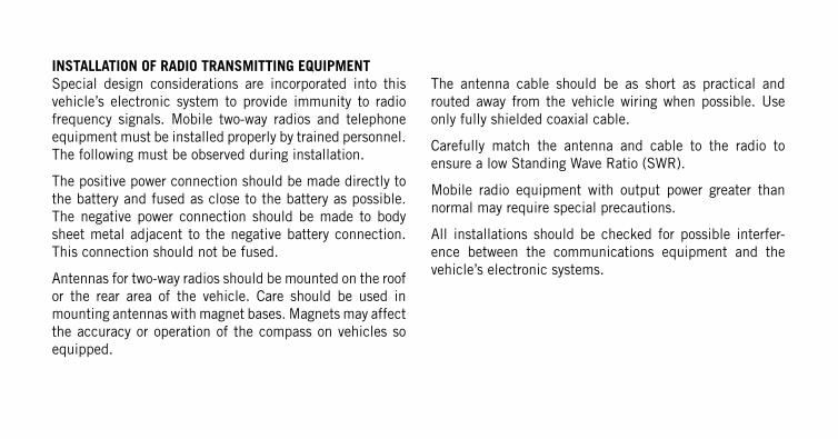
INSTALLATION OF RADIO TRANSMITTING EQUIPMENTSpecial design considerations are incorporated into thisvehicle’s electronic system to provide immunity to radiofrequency signals. Mobile two-way radios and telephoneequipment must be installed properly by trained personnel.The following must be observed during installation.
The positive power connection should be made directly tothe battery and fused as close to the battery as possible.The negative power connection should be made to bodysheet metal adjacent to the negative battery connection.This connection should not be fused.
Antennas for two-way radios should be mounted on the roofor the rear area of the vehicle. Care should be used inmounting antennas with magnet bases. Magnets may affectthe accuracy or operation of the compass on vehicles soequipped.
The antenna cable should be as short as practical androuted away from the vehicle wiring when possible. Useonly fully shielded coaxial cable.
Carefully match the antenna and cable to the radio toensure a low Standing Wave Ratio (SWR).
Mobile radio equipment with output power greater thannormal may require special precautions.
All installations should be checked for possible interfer-ence between the communications equipment and thevehicle’s electronic systems.
ViperChrysler Group LLC
OWNER ’S MANUAL
2014
20
14
Vip
er
14ZD-126-AA First Edition Printed in U.S.A.