2013 Edition FlangEd Fittings
33
2013 EDITION FLANGED FITTINGS DUCTILE IRON INDUSTRIAL APPLICATIONS, WATER & WASTEWATER 30"-64" NSF ® Certified to ANSI/NSF 61
Transcript of 2013 Edition FlangEd Fittings

2 0 1 3 E d i t i o n
FlangEd FittingsductilE iron
industrial applications, watEr & wastEwatEr
30"-64"
NSF®
Certified toANSI/NSF 61
Flanged FittingsNSF®
Certified toANSI/NSF 61
p 2866.
DIP.
PIPE
2 0 1 3 E d i t i o n
REVISED 10.13U.S. PiPE And FoUndRY Co. FLAnGEd di FittinGS BRo-101
table of contentsFlanged Fittings for Water 3Flange Details 5Flanged Fittings 6 90º and 45º Bend 6 22-1/2º and 11-1/4º Bends 7 Tees 8 Crosses 11 90˚ Base Bends 14 Base Tees 15
Base Drilling Details for Base Bends and Tees 18
Concentric Reducers 19
Eccentric Reducers 21
90º Long Radius Bends 23 Reducing Bends 90˚ 24 Blind Flanges 25 Wye Branches 26 True Wyes 27
Straight Flare 28Flange and Flare 90º Bends (Standard and Long Radius) 29
Method of Designating Outlets of Reducing Fittings in Specifications 30
Method of Designating Location of Tapped Holes When Specified 31
Combination of Standard Fittings That May be Used in Place of Special Fittings 32
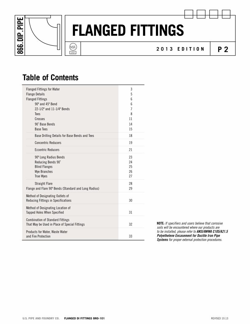
Products for Water, Waste Water and Fire Protection 33
Note: If specifiers and users believe that corrosive soils will be encountered where our products are to be installed, please refer to ANSI/AWWA C105/A21.5 Polyethelene Encasement for Ductile Iron Pipe Systems for proper external protection procedures.
Flanged FittingsNSF®
Certified toANSI/NSF 61
p 3866.
DIP.
PIPE
2 0 1 3 E d i t i o n
REVISED 10.13U.S. PiPE And FoUndRY Co. FLAnGEd di FittinGS BRo-101
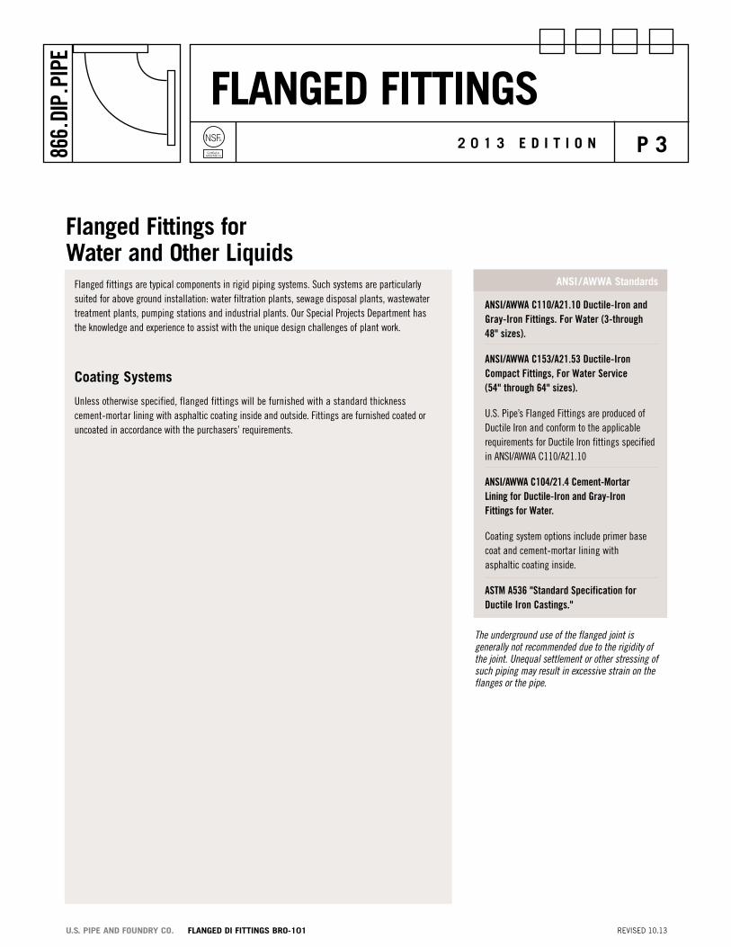
Flanged Fittings for water and other liquids
ANSI/AWWA C110/A21.10 Ductile-Iron and Gray-Iron Fittings. For Water (3-through 48" sizes).
ANSI/AWWA C153/A21.53 Ductile-Iron Compact Fittings, For Water Service (54" through 64" sizes).
U.S. Pipe’s Flanged Fittings are produced of Ductile Iron and conform to the applicable requirements for Ductile Iron fittings specified in ANSI/AWWA C110/A21.10
ANSI/AWWA C104/21.4 Cement-Mortar Lining for Ductile-Iron and Gray-Iron Fittings for Water.
Coating system options include primer base coat and cement-mortar lining with asphaltic coating inside.
AStM A536 "Standard Specification for Ductile Iron Castings."
ansi /awwa standardsFlanged fittings are typical components in rigid piping systems. Such systems are particularly suited for above ground installation: water filtration plants, sewage disposal plants, wastewater treatment plants, pumping stations and industrial plants. Our Special Projects Department has the knowledge and experience to assist with the unique design challenges of plant work.
coating systems
Unless otherwise specified, flanged fittings will be furnished with a standard thickness cement-mortar lining with asphaltic coating inside and outside. Fittings are furnished coated or uncoated in accordance with the purchasers’ requirements.
The underground use of the flanged joint is generally not recommended due to the rigidity of the joint. Unequal settlement or other stressing of such piping may result in excessive strain on the flanges or the pipe.

Flanged FittingsNSF®
Certified toANSI/NSF 61
p 4866.
DIP.
PIPE
2 0 1 3 E d i t i o n
REVISED 10.13U.S. PiPE And FoUndRY Co. FLAnGEd di FittinGS BRo-101
accessoriesThe gaskets and bolts to be used with flanged pipe and fittings should be selected by the purchaser with due consideration for the particular service and installation requirements. Flanged joint accessories (bolts, nuts and gaskets) can be furnished by U.S. Pipe if so specified. U.S. Pipe's FULL FACE FLANGE-TYTE™ Gaskets or RING FLANGE-TYTE™ Gaskets (4" through 64"size) are recommended for all flanged joints.
Flange compatibility and pressure ratingsThe flanges of ANSI/AWWA C110/A21.10 and C153/A21.53 standards conform to the drilling and facing of ANSI B16.1 Class 125 flanges. This B16.1 Class 125 designation leads some to conclude that these AWWA flanges are only rated at 125 psi service which is not correct. ANSI/AWWA C110/A21.10 flanged fittings are rated for 350 psi operating pressure for 3" through 12" sizes, 250 psi operating pressure for 14" through 48" sizes and ANSI/AWWA C153/A21.53 fittings are rated for 150 psi operating pressure for 54" through 64" sizes. These ratings are at ambient temperatures with at least a 2:1 factor of safety. Special gaskets such as U.S. Pipe’s FULL FACE FLANGE-TYTE™ Gaskets or RING FLANGE-TYTE™ Gaskets are required for operating pressures greater than 250 psi.
(Flanges of Ductile Iron fittings meeting the requirements of ANSI/AWWA C110/A21.10 cannot be joined with Class 250 ANSI B16.1 flanges.)
special service requirementsWhen requesting prices for flanged piping other than water service, please furnish complete information regarding the type of material to be conveyed, composition, concentration, pH, pressure and temperature.
Flanged Fittings for water and other liquids (cont.)
Note: U.S. Pipe recommends the use of FULL FACE FLANGE-TYTE® Gaskets or RING FLANGE-TYTE® Gaskets with Ductile Iron flanged joint products supplied by U.S. Pipe. These gaskets were designed specifically for the unique surface of Ductile Iron. Flat rubber gaskets are NOT considered equal in performance and may not provide the sealing capability the project requires. In addition, their use could result in unintended damage to the flanges and threads of the fabricated pipe by applying excess torque to the bolts/flanges in order to seal the joint.
Flanged FittingsNSF®
Certified toANSI/NSF 61
p 5866.
DIP.
PIPE
2 0 1 3 E d i t i o n
REVISED 10.13U.S. PiPE And FoUndRY Co. FLAnGEd di FittinGS BRo-101
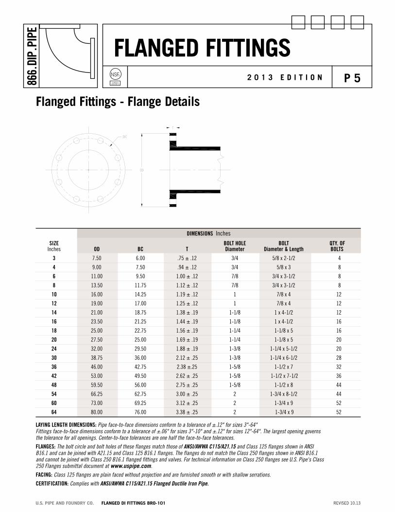
DIMeNSIoNS Inches
SIze BoLt HoLe BoLt Qty. oF Inches oD BC t Diameter Diameter & Length BoLtS
3 7.50 6.00 .75 ± .12 3/4 5/8 x 2-1/2 4
4 9.00 7.50 .94 ± .12 3/4 5/8 x 3 8
6 11.00 9.50 1.00 ± .12 7/8 3/4 x 3-1/2 8
8 13.50 11.75 1.12 ± .12 7/8 3/4 x 3-1/2 8
10 16.00 14.25 1.19 ± .12 1 7/8 x 4 12
12 19.00 17.00 1.25 ± .12 1 7/8 x 4 12
14 21.00 18.75 1.38 ± .19 1-1/8 1 x 4-1/2 12
16 23.50 21.25 1.44 ± .19 1-1/8 1 x 4-1/2 16
18 25.00 22.75 1.56 ± .19 1-1/4 1-1/8 x 5 16
20 27.50 25.00 1.69 ± .19 1-1/4 1-1/8 x 5 20
24 32.00 29.50 1.88 ± .19 1-3/8 1-1/4 x 5-1/2 20
30 38.75 36.00 2.12 ± .25 1-3/8 1-1/4 x 6-1/2 28
36 46.00 42.75 2.38 ±.25 1-5/8 1-1/2 x 7 32
42 53.00 49.50 2.62 ± .25 1-5/8 1-1/2 x 7-1/2 36
48 59.50 56.00 2.75 ± .25 1-5/8 1-1/2 x 8 44
54 66.25 62.75 3.00 ± .25 2 1-3/4 x 8-1/2 44
60 73.00 69.25 3.12 ± .25 2 1-3/4 x 9 52
64 80.00 76.00 3.38 ± .25 2 1-3/4 x 9 52
LAyING LeNGtH DIMeNSIoNS: Pipe face-to-face dimensions conform to a tolerance of ±.12" for sizes 3"-64" Fittings face-to-face dimensions conform to a tolerance of ±.06" for sizes 3"-10" and ±.12" for sizes 12"-64". The largest opening governs the tolerance for all openings. Center-to-face tolerances are one half the face-to-face tolerances.
FLANGeS: The bolt circle and bolt holes of these flanges match those of ANSI/AWWA C115/A21.15 and Class 125 flanges shown in ANSI B16.1 and can be joined with A21.15 and Class 125 B16.1 flanges. The flanges do not match the Class 250 flanges shown in ANSI B16.1 and cannot be joined with Class 250 B16.1 flanged fittings and valves. For technical information on Class 250 flanges see U.S. Pipe's Class 250 Flanges submittal document at www.uspipe.com.
FACING: Class 125 flanges are plain faced without projection and are furnished smooth or with shallow serrations.
CeRtIFICAtIoN: Complies with ANSI/AWWA C115/A21.15 Flanged Ductile Iron Pipe.
Flanged Fittings - Flange details

Flanged FittingsNSF®
Certified toANSI/NSF 61
p 6866.
DIP.
PIPE
2 0 1 3 E d i t i o n
REVISED 10.13U.S. PiPE And FoUndRY Co. FLAnGEd di FittinGS BRo-101
Note: Actual weights of fittings, sizes 54"-64", may exceed those shown.
For flange details see page 5.
Sizes 30"-48" conform to ANSI/AWWA C110/A2l.10.
Sizes 54"-64" conform to ANSI/AWWA C153/A21.53.
DIMeNSIoNS WeIGHt PReSSuRe Inches Pounds SIze RAtING 90º 45º 90º 45º Inches psi t A R A R
30 250 1.03 25.0 21.5 15.0 27.75 1430 1120
36 250 1.15 28.0 24.5 18.0 35.00 2380 1966
42 250 1.28 31.0 27.5 21.0 42.25 3271 3138
48 250 1.42 34.0 30.5 24.0 49.50 4755 3580
54 150 1.55 39.0 34.5 20.5 42.34 6085 4344
60 150 1.50 43.0 36.5 23.5 44.08 7705 5493
64 150 1.50 48.0 38.8 25.0 45.85 9197 6635
Flanged Fittings - 90º and 45º Bends
Flanged FittingsNSF®
Certified toANSI/NSF 61
p 7866.
DIP.
PIPE
2 0 1 3 E d i t i o n
REVISED 10.13U.S. PiPE And FoUndRY Co. FLAnGEd di FittinGS BRo-101
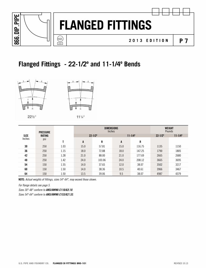
Note: Actual weights of fittings, sizes 54"-64", may exceed those shown.
For flange details see page 5.
Sizes 30"-48" conform to ANSI/AWWA C110/A2l.10.
Sizes 54"-64" conform to ANSI/AWWA C153/A21.53.
DIMeNSIoNS WeIGHt PReSSuRe Inches Pounds SIze RAtING 22-1/2º 11-1/4º 22-1/2º 11-1/4º Inches psi t A R A R 30 250 1.03 15.0 57.81 15.0 116.75 1135 1150
36 250 1.15 18.0 72.88 18.0 147.25 1790 1805
42 250 1.28 21.0 88.00 21.0 177.69 2665 2680
48 250 1.42 24.0 103.06 24.0 208.12 3665 3695
54 150 1.55 14.0 37.65 12.0 38.07 3502 3217
60 150 1.50 14.0 38.36 10.5 40.61 3966 3467
64 150 1.50 13.5 39.06 9.5 38.07 4987 4379
Flanged Fittings - 22-1/2º and 11-1/4º Bends

Flanged FittingsNSF®
Certified toANSI/NSF 61
p 8866.
DIP.
PIPE
2 0 1 3 E d i t i o n
REVISED 10.13U.S. PiPE And FoUndRY Co. FLAnGEd di FittinGS BRo-101
Note: Actual weights of fittings, sizes 54"-64", may exceed those shown.
Flanged Fittings - tees
SIze PReSSuRe RAtING DIMeNSIoNS WeIGHt Inches psi Inches Pounds
RuN BRANCH t t1 H J tee
30 06 250 1.03 .55 18.0 23.0 1366
30 08 250 1.03 .60 18.0 23.0 1388
30 10 250 1.03 .68 18.0 23.0 1408
30 12 250 1.03 .75 18.0 23.0 1436
30 14 250 1.03 .66 18.0 23.0 1603
30 16 250 1.03 .70 18.0 23.0 1634
30 18 250 1.03 .75 18.0 23.0 1889
30 20 250 1.03 .80 18.0 23.0 1934
30 24 250 1.03 .89 25.0 25.0 2218
30 30 250 1.03 1.03 25.0 25.0 2451
36 06 250 1.15 .55 20.0 26.0 2330
36 08 250 1.15 .60 20.0 26.0 2351
36 10 250 1.15 .68 20.0 26.0 2370
36 12 250 1.15 .75 20.0 26.0 2395
36 14 250 1.15 .66 20.0 26.0 2436
36 16 250 1.15 .70 20.0 26.0 2465
36 18 250 1.15 .75 20.0 26.0 2493
36 20 250 1.15 .80 20.0 26.0 2533
36 24 250 1.15 .89 20.0 26.0 2618
36 30 250 1.15 1.03 28.0 28.0 2919
36 36 250 1.15 1.15 28.0 28.0 3268

Flanged FittingsNSF®
Certified toANSI/NSF 61
p 9866.
DIP.
PIPE
2 0 1 3 E d i t i o n
REVISED 10.13U.S. PiPE And FoUndRY Co. FLAnGEd di FittinGS BRo-101
Note: Actual weights of fittings, sizes 54"-64", may exceed those shown.
SIze PReSSuRe RAtING DIMeNSIoNS WeIGHt Inches psi Inches Pounds
RuN BRANCH t t1 H J tee
42 12 250 1.28 .75 23.0 30.0 3417
42 14 250 1.28 .66 23.0 30.0 3457
42 16 250 1.28 .70 23.0 30.0 3485
42 18 250 1.28 .75 23.0 30.0 3512
42 20 250 1.28 .80 23.0 30.0 3551
42 24 250 1.28 .89 23.0 30.0 3631
42 30 250 1.28 1.03 31.0 31.0 4742
42 36 250 1.78 1.58 31.0 31.0 4980
42 42 250 1.78 1.78 31.0 31.0 5476
48 12 250 1.42 .75 26.0 34.0 5170
48 14 250 1.42 .66 26.0 34.0 5208
48 16 250 1.42 .70 26.0 34.0 5235
48 18 250 1.42 .75 26.0 34.0 5261
48 20 250 1.42 .80 26.0 34.0 5299
48 24 250 1.42 .89 26.0 34.0 5375
48 30 250 1.42 1.03 26.0 34.0 5476
48 36 250 1.42 1.15 34.0 34.0 6575
48 42 250 1.96 1.78 34.0 34.0 6892
48 48 250 1.96 1.96 34.0 34.0 7559
54 30 150 1.55 1.00 31.0 37.0 5918
54 36 150 1.55 1.15 31.0 37.0 6044
54 42 150 1.55 1.28 39.0 39.0 7432
54 48 150 1.55 1.42 39.0 39.0 7661
54 54 150 1.55 1.55 39.0 39.0 8277
Flanged Fittings - tees (cont.)

Flanged FittingsNSF®
Certified toANSI/NSF 61
p 10866.
DIP.
PIPE
2 0 1 3 E d i t i o n
REVISED 10.13U.S. PiPE And FoUndRY Co. FLAnGEd di FittinGS BRo-101
Flanged Fittings - tees (cont.)
Note: Actual weights of fittings, sizes 54"-64", may exceed those shown.
SIze PReSSuRe RAtING DIMeNSIoNS WeIGHt Inches psi Inches Pounds RuN BRANCH t t1 H J tee
60 30 150 1.50 1.00 33.0 42.0 7204
60 36 150 1.50 1.15 33.0 42.0 7357
60 42 150 1.50 1.28 43.0 43.0 9058
60 48 150 1.50 1.42 43.0 43.0 9291
60 54 150 1.50 1.55 43.0 43.0 9678
60 60 150 1.50 1.50 43.0 43.0 10369
64 36 150 1.50 1.15 32.0 44.0 8584
64 42 150 1.50 1.28 48.0 45.0 11322
64 48 150 1.50 1.42 48.0 45.0 11521
64 54 150 1.50 1.55 48.0 46.0 11914
64 60 150 1.50 1.50 48.0 46.0 12368
64 64 150 1.50 1.50 48.0 48.0 13466

Flanged FittingsNSF®
Certified toANSI/NSF 61
p 11866.
DIP.
PIPE
2 0 1 3 E d i t i o n
REVISED 10.13U.S. PiPE And FoUndRY Co. FLAnGEd di FittinGS BRo-101
Note: Actual weights of fittings, sizes 54"-64", may exceed those shown.
Flanged Fittings - crosses
SIze PReSSuRe RAtING DIMeNSIoNS WeIGHt Inches psi Inches Pounds
RuN BRANCH t t1 H J CRoSS
30 06 250 1.03 .55 11.0 23.0 1404
30 08 250 1.03 .60 11.0 23.0 1448
30 10 250 1.03 .68 11.0 23.0 1489
30 12 250 1.03 .75 11.0 23.0 1543
30 14 250 1.03 .66 18.0 23.0 1977
30 16 250 1.03 .70 18.0 23.0 2039
30 18 250 1.03 .75 18.0 23.0 2103
30 20 250 1.03 .80 18.0 23.0 2193
30 24 250 1.03 .89 25.0 25.0 2810
30 30 250 1.03 1.03 25.0 25.0 3276
36 06 250 1.15 .55 20.0 26.0 2537
36 08 250 1.15 .60 20.0 26.0 2579
36 10 250 1.15 .68 20.0 26.0 2617
36 12 250 1.15 .75 20.0 26.0 2667
36 14 250 1.15 .66 20.0 26.0 2749
36 16 250 1.15 .70 20.0 26.0 2806
36 18 250 1.15 .75 20.0 26.0 2862
36 20 250 1.15 .80 20.0 26.0 2943
36 24 250 1.15 .89 20.0 26.0 3114
36 30 250 1.15 1.03 28.0 28.0 4020
36 36 250 1.15 1.15 28.0 28.0 4754

Flanged FittingsNSF®
Certified toANSI/NSF 61
p 12866.
DIP.
PIPE
2 0 1 3 E d i t i o n
REVISED 10.13U.S. PiPE And FoUndRY Co. FLAnGEd di FittinGS BRo-101
SIze PReSSuRe RAtING DIMeNSIoNS WeIGHt Inches psi Inches Pounds
RuN BRANCH t t1 H J CRoSS
42 12 250 1.28 .75 23.0 30.0 3786
42 14 250 1.28 .66 23.0 30.0 3865
42 16 250 1.28 .70 23.0 30.0 3921
42 18 250 1.28 .75 23.0 30.0 3975
42 20 250 1.28 .80 23.0 30.0 4053
42 24 250 1.28 .89 23.0 30.0 4214
42 30 250 1.28 1.03 31.0 31.0 5197
42 36 250 1.78 1.58 31.0 31.0 5673
42 42 250 1.78 1.78 31.0 31.0 6663
48 12 250 1.42 .75 26.0 34.0 5275
48 14 250 1.42 .66 26.0 34.0 5351
48 16 250 1.42 .70 26.0 34.0 5405
48 18 250 1.42 .75 26.0 34.0 5457
48 20 250 1.42 .80 26.0 34.0 5532
48 24 250 1.42 .89 26.0 34.0 5685
48 30 250 1.42 1.03 26.0 34.0 5887
48 36 250 1.42 1.15 34.0 34.0 7187
48 42 250 1.96 1.78 34.0 34.0 7820
48 48 250 1.96 1.96 34.0 34.0 9156
54 30 150 1.55 1.00 31.0 37.0 6105
54 36 150 1.55 1.15 31.0 37.0 6358
54 42 150 1.55 1.28 39.0 39.0 8004
54 48 150 1.55 1.42 39.0 39.0 8462
54 54 150 1.55 1.55 39.0 39.0 9694
Note: Actual weights of fittings, sizes 54"-64", may exceed those shown.
Flanged Fittings - crosses (cont.)

Flanged FittingsNSF®
Certified toANSI/NSF 61
p 13866.
DIP.
PIPE
2 0 1 3 E d i t i o n
REVISED 10.13U.S. PiPE And FoUndRY Co. FLAnGEd di FittinGS BRo-101
Flanged Fittings - crosses (cont.)
Note: Actual weights of fittings, sizes 54"-64", may exceed those shown.
SIze PReSSuRe RAtING DIMeNSIoNS WeIGHt Inches psi Inches Pounds RuN BRANCH t t1 H J CRoSS
60 30 150 1.50 1.00 33.0 42.0 7472
60 36 150 1.50 1.15 33.0 42.0 7779
60 42 150 1.50 1.28 43.0 43.0 9718
60 48 150 1.50 1.42 43.0 43.0 10185
60 54 150 1.50 1.55 43.0 43.0 10959
60 60 150 1.50 1.50 43.0 43.0 12341
64 36 150 1.50 1.15 32.0 44.0 8998
64 42 150 1.50 1.28 48.0 45.0 11984
64 48 150 1.50 1.42 48.0 45.0 12382
64 54 150 1.50 1.55 48.0 46.0 13167
64 60 150 1.50 1.50 48.0 46.0 14076
64 64 150 1.50 1.50 48.0 48.0 16272

Flanged FittingsNSF®
Certified toANSI/NSF 61
p 14866.
DIP.
PIPE
2 0 1 3 E d i t i o n
REVISED 10.13U.S. PiPE And FoUndRY Co. FLAnGEd di FittinGS BRo-101
Flanged Fittings - 90º Base Bends
Note: Actual weights of fittings, sizes 54"-64", may exceed those shown.
For flange detail see page 5.
Dimension “R” is a finished dimension; unfinished bases will be 1/8" longer. For base drilling details see page 18. *Not included in AWWA C110 or C153
SIze PReSSuRe DIMeNSIoNS WeIGHt Inches RAtING Inches Pounds psi R S DIAMeteR t u BASe BeND BASe oNLy
30 250 23.00 16.00 1.19 1.15 1620 190
36 250 26.00 19.00 1.25 1.15 2385 250
42 250 30.00 23.50 1.44 1.28 3465 410
48 250 34.00 25.00 1.56 1.42 4610 515
54* 250 38.00 27.50 1.69 1.55 6841 1050
60* 250 42.00 32.00 1.88 1.75 8851 1500
64* 250 44.00 38.75 2.12 1.75 11731 2250
Flanged FittingsNSF®
Certified toANSI/NSF 61
p 15866.
DIP.
PIPE
2 0 1 3 E d i t i o n
REVISED 10.13U.S. PiPE And FoUndRY Co. FLAnGEd di FittinGS BRo-101
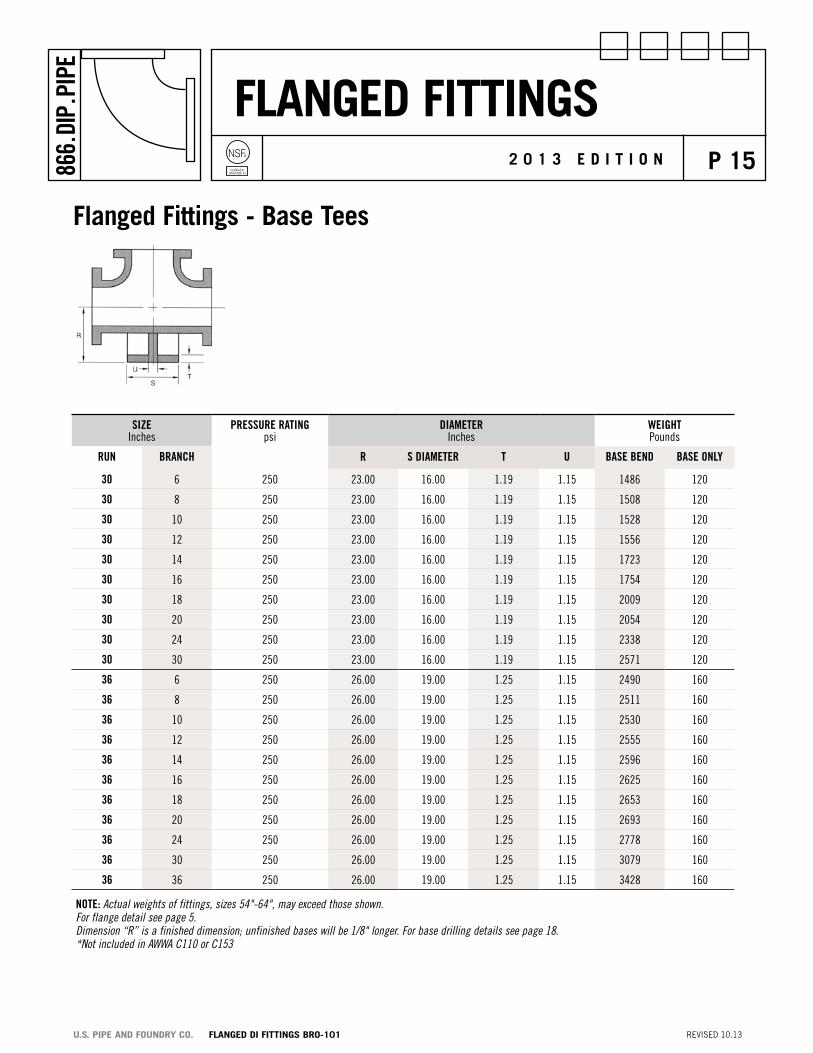
Flanged Fittings - Base tees
SIzeInches
PReSSuRe RAtINGpsi
DIAMeteRInches
WeIGHtPounds
RuN BRANCH R S DIAMeteR t u BASe BeND BASe oNLy
30 6 250 23.00 16.00 1.19 1.15 1486 120
30 8 250 23.00 16.00 1.19 1.15 1508 120
30 10 250 23.00 16.00 1.19 1.15 1528 120
30 12 250 23.00 16.00 1.19 1.15 1556 120
30 14 250 23.00 16.00 1.19 1.15 1723 120
30 16 250 23.00 16.00 1.19 1.15 1754 120
30 18 250 23.00 16.00 1.19 1.15 2009 120
30 20 250 23.00 16.00 1.19 1.15 2054 120
30 24 250 23.00 16.00 1.19 1.15 2338 120
30 30 250 23.00 16.00 1.19 1.15 2571 120
36 6 250 26.00 19.00 1.25 1.15 2490 160
36 8 250 26.00 19.00 1.25 1.15 2511 160
36 10 250 26.00 19.00 1.25 1.15 2530 160
36 12 250 26.00 19.00 1.25 1.15 2555 160
36 14 250 26.00 19.00 1.25 1.15 2596 160
36 16 250 26.00 19.00 1.25 1.15 2625 160
36 18 250 26.00 19.00 1.25 1.15 2653 160
36 20 250 26.00 19.00 1.25 1.15 2693 160
36 24 250 26.00 19.00 1.25 1.15 2778 160
36 30 250 26.00 19.00 1.25 1.15 3079 160
36 36 250 26.00 19.00 1.25 1.15 3428 160
Note: Actual weights of fittings, sizes 54"-64", may exceed those shown.For flange detail see page 5. Dimension “R” is a finished dimension; unfinished bases will be 1/8" longer. For base drilling details see page 18.*Not included in AWWA C110 or C153

Flanged FittingsNSF®
Certified toANSI/NSF 61
p 16866.
DIP.
PIPE
2 0 1 3 E d i t i o n
REVISED 10.13U.S. PiPE And FoUndRY Co. FLAnGEd di FittinGS BRo-101
SIzeInches
PReSSuRe RAtINGpsi
DIAMeteRInches
WeIGHtPounds
RuN BRANCH R S DIAMeteR t u BASe BeND BASe oNLy
42 12 250 30.00 23.50 1.44 1.28 3687 270
42 14 250 30.00 23.50 1.44 1.28 3727 270
42 16 250 30.00 23.50 1.44 1.28 3755 270
42 18 250 30.00 23.50 1.44 1.28 3782 270
42 20 250 30.00 23.50 1.44 1.28 3821 270
42 24 250 30.00 23.50 1.44 1.28 3901 270
42 30 250 30.00 23.50 1.44 1.28 5012 270
42 36 250 30.00 23.50 1.44 1.28 5250 270
42 42 250 30.00 23.50 1.44 1.28 5746 270
48 12 250 34.00 25.00 1.56 1.42 5505 335
48 14 250 34.00 25.00 1.56 1.42 5543 335
48 16 250 34.00 25.00 1.56 1.42 5570 335
48 18 250 34.00 25.00 1.56 1.42 5596 335
48 20 250 34.00 25.00 1.56 1.42 5634 335
48 24 250 34.00 25.00 1.56 1.42 5710 335
48 30 250 34.00 25.00 1.56 1.42 5811 335
48 36 250 34.00 25.00 1.56 1.42 6910 335
48 42 250 34.00 25.00 1.56 1.42 7227 335
48 48 250 34.00 25.00 1.56 1.42 7894 335
Flanged Fittings - Base tees (cont.)
Note: Actual weights of fittings, sizes 54"-64", may exceed those shown.For flange detail see page 5. Dimension “R” is a finished dimension; unfinished bases will be 1/8" longer. For base drilling details see page 18.*Not included in AWWA C110 or C153

Flanged FittingsNSF®
Certified toANSI/NSF 61
p 17866.
DIP.
PIPE
2 0 1 3 E d i t i o n
REVISED 10.13U.S. PiPE And FoUndRY Co. FLAnGEd di FittinGS BRo-101
Flanged Fittings - Base tees (cont.)
SIzeInches
PReSSuRe RAtINGpsi
DIAMeteRInches
WeIGHtPounds
RuN BRANCH R S DIAMeteR t u BASe BeND BASe oNLy
54 30 250 38.00 27.50 1.69 1.55 6483 565
54 36 250 38.00 27.50 1.69 1.55 6609 565
54 42 250 38.00 27.50 1.69 1.55 7997 565
54 48 250 38.00 27.50 1.69 1.55 8226 565
54 54 250 38.00 27.50 1.69 1.55 8842 565
60 36 250 42.00 32.00 1.88 1.75 8212 855
60 42 250 42.00 32.00 1.88 1.75 9913 855
60 48 250 42.00 32.00 1.88 1.75 10146 855
60 54 250 42.00 32.00 1.88 1.75 10533 855
60 60 250 42.00 32.00 1.88 1.75 11224 855
64 36 250 44.00 38.75 2.12 1.75 9859 1275
64 42 250 44.00 38.75 2.12 1.75 12597 1275
64 48 250 44.00 38.75 2.12 1.75 12796 1275
64 54 250 44.00 38.75 2.12 1.75 13189 1275
64 60 250 44.00 38.75 2.12 1.75 13643 1275
64 64 250 44.00 38.75 2.12 1.75 14741 1275
Note: Actual weights of fittings, sizes 54"-64", may exceed those shown.For flange detail see page 5. Dimension “R” is a finished dimension; unfinished bases will be 1/8" longer. For base drilling details see page 18.*Not included in AWWA C110 or C153
Flanged FittingsNSF®
Certified toANSI/NSF 61
p 18866.
DIP.
PIPE
2 0 1 3 E d i t i o n
REVISED 10.13U.S. PiPE And FoUndRY Co. FLAnGEd di FittinGS BRo-101
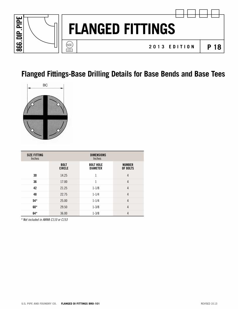
SIze FIttING DIMeNSIoNS Inches Inches
BoLt BoLt HoLe NuMBeR CIRCLe DIAMeteR oF BoLtS
30 14.25 1 4
36 17.00 1 4
42 21.25 1-1/8 4
48 22.75 1-1/4 4
54* 25.00 1-1/4 4
60* 29.50 1-3/8 4
64* 36.00 1-3/8 4
Flanged Fittings-Base drilling details for Base Bends and Base tees
* Not included in AWWA C110 or C153

Flanged FittingsNSF®
Certified toANSI/NSF 61
p 19866.
DIP.
PIPE
2 0 1 3 E d i t i o n
REVISED 10.13U.S. PiPE And FoUndRY Co. FLAnGEd di FittinGS BRo-101
Certified toANSI/NSF 61
Flanged Fittings - concentric reducers
Concentric
SIze PReSSuRe RAtING DIMeNSIoNS WeIGHt Inches psi Inches Pounds
RuN BRANCH t t1 L
30 12 250 1.03 .75 30 962
30 14 250 1.03 .66 30 1101
30 16 250 1.03 .70 30 1066
30 18 250 1.03 .75 30 1121
30 20 250 1.03 .80 30 1065
30 24 250 1.03 .89 30 1196
36 14 250 1.15 .66 36 1290
36 16 250 1.15 .70 36 1115
36 18 250 1.15 .75 36 1548
36 20 250 1.15 .80 36 1626
36 24 250 1.15 .89 36 1393
36 30 250 1.15 1.03 36 1578
42 20 250 1.28 .80 42 2187
42 24 250 1.28 .89 42 2366
42 30 250 1.28 1.03 42 1848
42 36 250 1.28 1.15 42 2104
48 24 250 1.42 .89 48 3080
48 30 250 1.42 1.03 48 3370
48 36 250 1.42 1.15 48 3237
48 42 250 1.42 1.28 48 3650
54 30 150 .90 1.00 32 2659
54 36 150 .90 1.15 28 2627
54 42 150 .90 1.25 25 2730
54 48 150 .90 1.40 18 2545

Flanged FittingsNSF®
Certified toANSI/NSF 61
p 20866.
DIP.
PIPE
2 0 1 3 E d i t i o n
REVISED 10.13U.S. PiPE And FoUndRY Co. FLAnGEd di FittinGS BRo-101
Note: Actual weights of fittings, sizes 54"-64" may exceed those shown.
Sizes 3"-48" conform to ANSI/AWWA C110/A21.10.
Sizes 54"-64" conform to ANSI/AWWA C153/A21.53.
For flange details see page 5.
On reducers of certain end combinations the number of bolt holes on one flange have an odd number in one quadrant and the opposite flange has an even number of holes in the same quadrant so that there are only four positions in which the reducers can be placed to properly assemble with the adjacent piping. Please take particular note that flange reducers have the vertical centerline marked on the edge of the flange. If assembled with the centerline in the vertical plane, the casting will properly assemble.
Flanged Fittings - concentric reducers (cont.)
SIze PReSSuRe RAtING DIMeNSIoNS WeIGHt Inches psi Inches Pounds
RuN BRANCH t t1 L
60 36 150 .94 1.15 32 3315
60 42 150 .94 1.25 26 3315
60 48 150 .94 1.40 20 3141
60 54 150 .94 .90 15 2925
64 36 150 .99 1.15 35 4163
64 42 150 .99 1.25 30 4178
64 48 150 .99 1.40 25 4103
64 54 150 .99 .90 18 3773
64 60 150 .99 .94 17 4100

Flanged FittingsNSF®
Certified toANSI/NSF 61
p 21866.
DIP.
PIPE
2 0 1 3 E d i t i o n
REVISED 10.13U.S. PiPE And FoUndRY Co. FLAnGEd di FittinGS BRo-101
Certified toANSI/NSF 61
Flanged Fittings - Eccentric reducers
eccentric
SIze PReSSuRe RAtING DIMeNSIoNS WeIGHt Inches psi Inches Pounds
RuN BRANCH t t1 L
30 12 250 1.03 .75 30 962
30 14 250 1.03 .66 30 1011
30 16 250 1.03 .70 30 1066
30 18 250 1.03 .75 30 1121
30 20 250 1.03 .80 30 1065
30 24 250 1.03 .89 30 1196
36 14 250 1.15 .66 – 1290
36 16 250 1.15 .70 – 1115
36 18 250 1.15 .75 36 1548
36 20 250 1.15 .80 36 1626
36 24 250 1.15 .89 36 1393
36 30 250 1.15 1.03 36 1578
42 20 250 1.28 .80 42 2187
42 24 250 1.28 .89 42 2366
42 30 250 1.28 1.03 42 1848
42 36 250 1.28 1.15 42 2104
48 24 250 1.42 .89 48 3080
48 30 250 1.42 1.03 48 3370
48 36 250 1.42 1.15 48 3237
48 42 250 1.42 1.28 48 3650
54 30 150 .90 1.00 41 2926
54 36 150 .90 1.15 28 2548
54 42 150 .90 1.25 25 2693
54 48 150 .90 1.40 18 2579

Flanged FittingsNSF®
Certified toANSI/NSF 61
p 22866.
DIP.
PIPE
2 0 1 3 E d i t i o n
REVISED 10.13U.S. PiPE And FoUndRY Co. FLAnGEd di FittinGS BRo-101
Note: Actual weights of fittings, sizes 54"-64" may exceed those shown.
Sizes 3"-48" conform to ANSI/AWWA C110/A21.10.
Sizes 54"-64" conform to ANSI/AWWA C153/A21.53.
For flange details see page 5.
On reducers of certain end combinations the number of bolt holes on one flange have an odd number in one quadrant and the opposite flange has an even number of holes in the same quadrant so that there are only four positions in which the reducers can be placed to properly assemble with the adjacent piping. Please take particular note that flange reducers have the vertical centerline marked on the edge of the flange. If assembled with the centerline in the vertical plane, the casting will properly assemble.
*Not included in AWWA C110 or C153
SIze PReSSuRe RAtING DIMeNSIoNS WeIGHt Inches psi Inches Pounds
RuN BRANCH t t1 L
60 42 150 .94 1.25 29 3663
60 48 150 .94 1.40 23 3429
60 54 150 .94 .90 15 2959
64 42 150 .99 1.25 – –
64 48 150 .99 1.40 – –
64 54 150 .99 .90 19.5 3989
64 60 150 .99 .94 17 4075
Flanged Fittings - Eccentric reducers (cont.)

Flanged FittingsNSF®
Certified toANSI/NSF 61
p 23866.
DIP.
PIPE
2 0 1 3 E d i t i o n
REVISED 10.13U.S. PiPE And FoUndRY Co. FLAnGEd di FittinGS BRo-101
Note: Thicknesses and Dimensions Conforming to ANSI B16.1
For flange details see page 5.
90º BeND LoNG RADIuS NoMINAL PReSSuRe WALL B WeIGHtS SIze RAtING tHICkNeSS Inches Pounds Inches psi Inches
30 250 1.03 41.5 2105
36 250 1.15 49 3285
42 250 1.28 56.5 4865
48 250 1.42 64 6790
Flanged Fittings – 90º long radius Bends
Flanged FittingsNSF®
Certified toANSI/NSF 61
p 24866.
DIP.
PIPE
2 0 1 3 E d i t i o n
REVISED 10.13U.S. PiPE And FoUndRY Co. FLAnGEd di FittinGS BRo-101
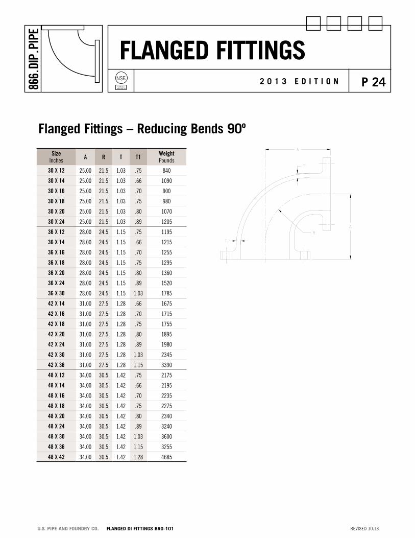
Flanged Fittings – reducing Bends 90º
SizeInches A R t t1 Weight
Pounds
30 X 12 25.00 21.5 1.03 .75 840
30 X 14 25.00 21.5 1.03 .66 1090
30 X 16 25.00 21.5 1.03 .70 900
30 X 18 25.00 21.5 1.03 .75 980
30 X 20 25.00 21.5 1.03 .80 1070
30 X 24 25.00 21.5 1.03 .89 1205
36 X 12 28.00 24.5 1.15 .75 1195
36 X 14 28.00 24.5 1.15 .66 1215
36 X 16 28.00 24.5 1.15 .70 1255
36 X 18 28.00 24.5 1.15 .75 1295
36 X 20 28.00 24.5 1.15 .80 1360
36 X 24 28.00 24.5 1.15 .89 1520
36 X 30 28.00 24.5 1.15 1.03 1785
42 X 14 31.00 27.5 1.28 .66 1675
42 X 16 31.00 27.5 1.28 .70 1715
42 X 18 31.00 27.5 1.28 .75 1755
42 X 20 31.00 27.5 1.28 .80 1895
42 X 24 31.00 27.5 1.28 .89 1980
42 X 30 31.00 27.5 1.28 1.03 2345
42 X 36 31.00 27.5 1.28 1.15 3390
48 X 12 34.00 30.5 1.42 .75 2175
48 X 14 34.00 30.5 1.42 .66 2195
48 X 16 34.00 30.5 1.42 .70 2235
48 X 18 34.00 30.5 1.42 .75 2275
48 X 20 34.00 30.5 1.42 .80 2340
48 X 24 34.00 30.5 1.42 .89 3240
48 X 30 34.00 30.5 1.42 1.03 3600
48 X 36 34.00 30.5 1.42 1.15 3255
48 X 42 34.00 30.5 1.42 1.28 4685

Flanged FittingsNSF®
Certified toANSI/NSF 61
p 25866.
DIP.
PIPE
2 0 1 3 E d i t i o n
REVISED 10.13U.S. PiPE And FoUndRY Co. FLAnGEd di FittinGS BRo-101
Certified toANSI/NSF 61
Note: Actual weights of fittings, sizes 54"-64", may exceed those shown.
For bolt hole details see page 5.
DIMeNSIoNS Inches
SIze PReSSuRe RAtING DIAMeteR tHICkNeSS WALL BLIND FLANGeS Inches psi oF FLANGe oF FLANGe tHICkNeSS Pounds o Q V
30 250 38.75 2.12 1.37 500
36 250 46.00 2.38 1.58 790
42 250 53.00 2.62 1.78 1175
48 250 59.50 2.75 1.96 1585
54 150 66.25 3.00 2.23 2260
60 150 73.00 3.12 2.63 2955
64 150 80.00 3.38 2.81 3855
Flanged Fittings – Blind Flanges
2" - 10"
12" - 48"

Flanged FittingsNSF®
Certified toANSI/NSF 61
p 26866.
DIP.
PIPE
2 0 1 3 E d i t i o n
REVISED 10.13U.S. PiPE And FoUndRY Co. FLAnGEd di FittinGS BRo-101
30 16 250 1.03 .70 49 10 49 3330
30 18 250 1.03 .75 49 10 49 3408
30 20 250 1.03 .80 49 10 49 3502
30 24 250 1.03 .89 49 10 49 3696
30 30 250 1.03 1.03 49 10 49 4056
36 16 250 1.15 .70 60 19.5 60 5368
36 18 250 1.15 .75 60 19.5 60 5469
36 20 250 1.15 .80 60 19.5 60 5592
36 24 250 1.15 .89 60 19.5 60 5818
36 30 250 1.15 1.03 60 19.5 60 6234
36 36 250 1.15 1.15 60 19.5 60 6681
42 24 250 1.78 1.16 69 20 69 8092
42 30 150 1.78 1.37 69 20 69 8544
42 36 150 1.78 1.58 69 20 69 9033
42 42 250 1.78 1.78 69 20 69 9667
48 24 250 1.96 1.16 77.5 21 77.5 11021
48 30 250 1.96 1.37 77.5 21 77.5 11504
48 36 250 1.96 1.58 77.5 21 77.5 12031
48 42 150 1.96 1.78 77.5 21 77.5 12705
48 48 150 1.96 1.96 77.5 21 77.5 13480
Flanged Fittings – wye Branches
SIze PReSSuRe RAtING DIMeNSIoNS WeIGHt Inches psi Inches Pounds
WALL tHICkNeSS A B C
RuN BRANCH RuN BRANCH
For flange details see page 5

Flanged FittingsNSF®
Certified toANSI/NSF 61
p 27866.
DIP.
PIPE
2 0 1 3 E d i t i o n
REVISED 10.13U.S. PiPE And FoUndRY Co. FLAnGEd di FittinGS BRo-101
For flange details see page 5.
SIze t R B L WeIGHt Inches Pounds
30 1.03 30 38.75 24 1100
36 1.15 10 46.00 24 1460
42 1.28 10 53.00 24 1534
48 1.42 10 59.50 24 1865
54 .90 10 25.00 24 2012
Flanged Fittings – straight Flare

Flanged FittingsNSF®
Certified toANSI/NSF 61
p 28866.
DIP.
PIPE
2 0 1 3 E d i t i o n
REVISED 10.13U.S. PiPE And FoUndRY Co. FLAnGEd di FittinGS BRo-101
For flange details see page 5.
Flange and Flare 90º Bends standard and long radiusMiscellaneous Flanged Fittings
DIMeNSIoNSInches
WeIGHtPounds
DIMeNSIoNSInches
WeIGHtPounds
StANDARD LoNG RADIuS
SIze A B CDIAMeteR
WALLt
SIze A B
30 25 36 38.75 1.03 1970 30 41.5 48.5 2190
36 28 38 46 1.15 2730 36 49 56 3465
42 31 35 53 1.28 3200 42 65.5 63.5 5150
48 34 46 59.5 1.42 5235 48 64 64 6750

Flanged FittingsNSF®
Certified toANSI/NSF 61
p 29866.
DIP.
PIPE
2 0 1 3 E d i t i o n
REVISED 10.13U.S. PiPE And FoUndRY Co. FLAnGEd di FittinGS BRo-101
Method of designating outlets of reducing Fittings in specifications
Note: The largest opening establishes the basic size of a reducing fitting. The largest opening is named first, except for bullhead tees which are reducing on both runs and for double branch elbows where both branches are reducing, the outlet is the largest opening and named last in both cases.
In designating the openings of reducing fittings they should be read in the order indicated by the sequence of the letters a, b, c and d. In designating the outlets of side outlet reducing fittings the side outlet is named last and in the case of the cross which is not shown the side outlet is designated by the letter e. Fittings of the configurations shown on this page that are not covered on pages 6 through 28 may be furnished on special order. Consult your nearest U.S. Pipe Sales Representative.

Flanged FittingsNSF®
Certified toANSI/NSF 61
p 30866.
DIP.
PIPE
2 0 1 3 E d i t i o n
REVISED 10.13U.S. PiPE And FoUndRY Co. FLAnGEd di FittinGS BRo-101
Note: The above sketches show two views of the same fitting and represent fittings with symmetrical shapes, with the exception of the side outlet elbow and the side outlet tee (straight sizes).
Fittings of the configurations shown on this page that are not covered on pages 6 through 28 may be furnished on special order. Consult your nearest U.S. Pipe Sales Representative.
Method of designating location of tapped Holes when specified

Flanged FittingsNSF®
Certified toANSI/NSF 61
p 31866.
DIP.
PIPE
2 0 1 3 E d i t i o n
REVISED 10.13U.S. PiPE And FoUndRY Co. FLAnGEd di FittinGS BRo-101
The illustrations in the “SPECIAL” columns on this page indicate typical fittings that are often required with a combination of bell, plain end, and flange outlets. The laying dimensions of these fittings are not covered by any standard and they are therefore usually named “SPECIAL” inasmuch as they are made to order to suit certain conditions in piping installations.
To the right of each “SPECIAL” fitting is shown a combination of Standard fittings that can be used to obtain the same outlet effects as the Specials. The laying dimensions may not be interchangeable since the dimensions of the Standard fittings are fixed whereas the Special can be made to a variety of desired lengths.
The use of Standard fittings wherever possible is always recommended as the most economical and such fittings can usually be shipped out of stock. In sending inquiries for fittings of dimensions deviating from the Standard, state specifically the type of outlets wanted, reading, sizes, etc., as shown on this page, and give exact dimension from the center line to outlet.
combination of standard Fittingsthat May be used in place of special Fittings

Flanged FittingsNSF®
Certified toANSI/NSF 61
p 32866.
DIP.
PIPE
2 0 1 3 E d i t i o n
REVISED 10.13U.S. PiPE And FoUndRY Co. FLAnGEd di FittinGS BRo-101
Products for Water, Wastewater and Fire Protectionductile iron pipe siZE rangE
TYTON JOINT® Pipe 3"-64" Ductile Iron
Mechanical Joint Pipe 4"-12" Ductile Iron
TR FLEX® Pipe 4"-36" Ductile Iron
HP LOK® Pipe 30"-64" Ductile Iron
Flanged Pipe 3"-64" Ductile Iron
Grooved Pipe 4”-36” Ductile Iron
USIFLEX® Boltless Ball Joint Pipe 4"-48" Ductile Iron For Subaqueous Installations
restrained Joints
TR FLEX® Restrained Joint 4"-36" Ductile Iron
HP LOK® Restrained Joint 30"-64" Ductile Iron
MJ FIELD LOK® Gaskets 4"-24"
FIELD LOK 350® Gaskets 4"-24"
FIELD LOK® Gasket 30" & 36"
TR FLEX GRIPPER® Rings 4"-36" Ductile Iron
TR TELE FLEX® Assemblies 4"-24" Ductile Iron
Fittings
TYTON® Fittings 14"-24" Ductile Iron
TRIM TYTON® Fittings 4”-12” Ductile Iron
TR FLEX® Fittings and TR FLEX® Telescoping Sleeves 4"-36" Ductile Iron
HP LOK® Fittings and HP LOK® Telescoping Sleeves 30”-64” Ductile Iron
Mechanical Joint Fittings 30"-48" Ductile Iron
Flanged Fittings 30"-64" Ductile Iron
XTRA FLEX® Couplings 4"-24" Ductile Iron
Miscellaneous products
PROTECTO 401™ Lined Ductile Iron Pipe for 4"-64" Ductile Iron Domestic Sewage and Industrial Wastes
GLASS Lined Ductile Iron Pipe for Wastewater 4”-30” Ductile Iron Treatment Plants
RING FLANGE-TYTE® Gaskets 4"-36"
FULL FACE FLANGE-TYTE® Gaskets 4"-64"
MJ Harness-Lok 4”-48” Ductile Iron
Saddle Outlets Various Ductile Iron
Welded Outlets Various Ductile Iron
Polyethylene Encasement 4"-64"
Our products are manufactured in conformance with National Standards so that our customers may be assured of getting the performance and longevity they expect. Use of accessories or other appurtenances that do not comply with recognized standards may jeopardize the performance and longevity of the project.

Flanged FittingsNSF®
Certified toANSI/NSF 61
p 33866.
DIP.
PIPE
2 0 1 3 E d i t i o n
P.o. BoX 10406BIRMINGHAM, AL 35202
866.DIP.PIPe (866.347.7473)FAX: 205.254.7165
eMAIL: [email protected]
All U.S. Pipe brochures and/or products are subject to change without further notice.