2012.02.01 - Cold-Formed Steel Design 2007 Edition - S100
54
b COLD-FORMED 2007 EDITI SE University, February 2012 b Roger L Wei-Wen Yu Center for Co Missouri University of S by STEEL DESIGN: ION – S100 1 by LaBoube old-Formed Steel Structures Science and Technology
description
steel desing
Transcript of 2012.02.01 - Cold-Formed Steel Design 2007 Edition - S100
by
COLD-FORMED STEEL DESIGN:
2007 EDITION
SE University, February 2012
by
Roger LaBoube
Wei-Wen Yu Center for Cold
Missouri University of Science and Technology
by
FORMED STEEL DESIGN:
2007 EDITION – S100
1
by
LaBoube
Yu Center for Cold-Formed Steel Structures
Missouri University of Science and Technology
What are the changes in 2007?
Why is cold-formed steel
so much more
complex than hot
SE University, February 2012
Or
Is it really that much different?
What are the changes in 2007?
formed steel
so much more
complex than hot-roll design?
2
Or
Is it really that much different?
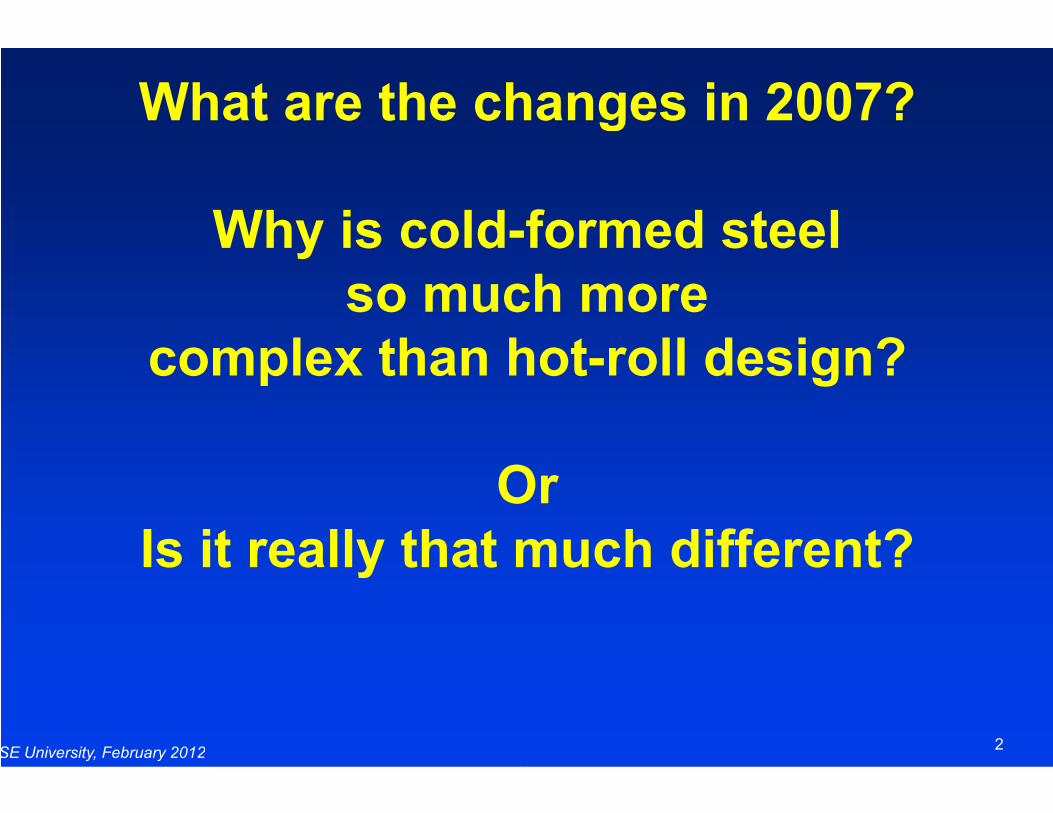
SOME TYPICAL COLD
CROSS SECTIONSStuds or Joists
SE University, February 2012
Other Shapes
SOME TYPICAL COLD-FORMED SHAPE
CROSS SECTIONS
3
Think about the behavior
SOME TYPICAL COLD
CROSS SECTIONS
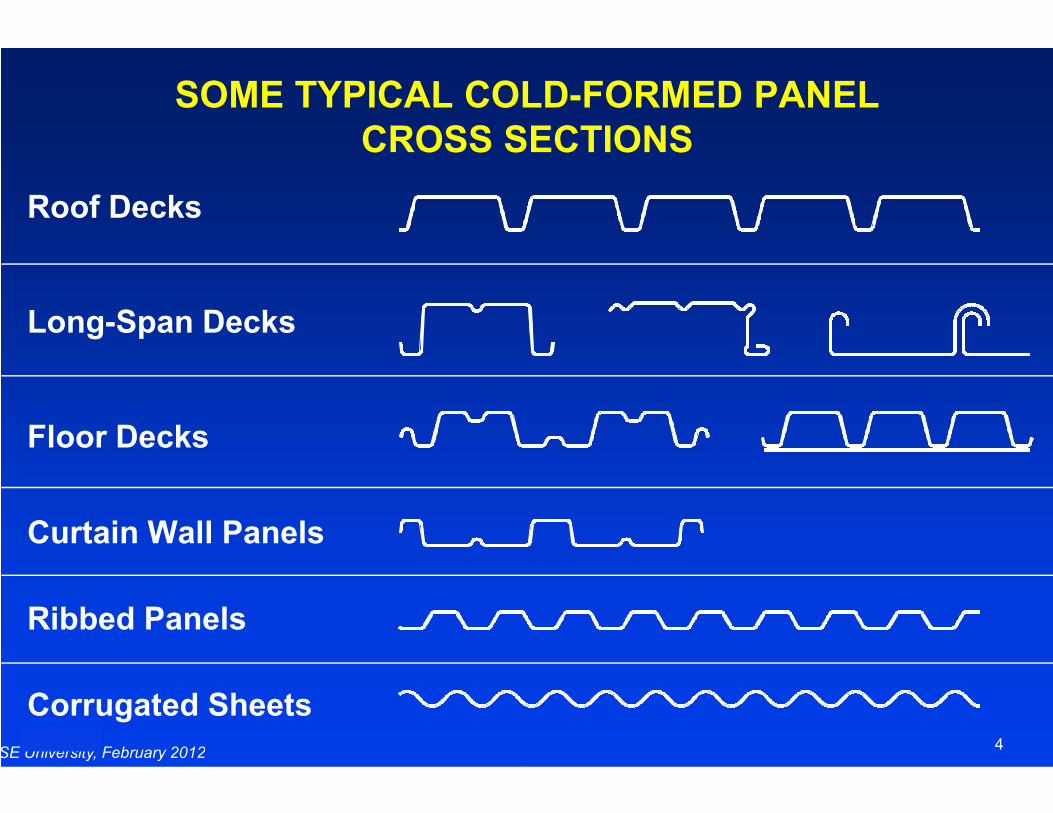
Roof Decks
Long-Span Decks
SE University, February 2012
Floor Decks
Curtain Wall Panels
Ribbed Panels
Corrugated Sheets
SOME TYPICAL COLD-FORMED PANEL
CROSS SECTIONS
4
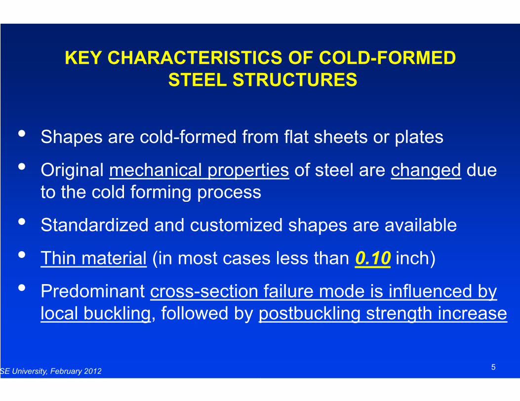
KEY CHARACTERISTICS OF COLD
STEEL STRUCTURES
• Shapes are cold-formed from flat sheets or plates
• Original mechanical propertiesto the cold forming process
SE University, February 2012
to the cold forming process
• Standardized and customized shapes are available
• Thin material (in most cases less than
• Predominant cross-section failure mode is influenced by local buckling, followed by postbuckling strength increase
KEY CHARACTERISTICS OF COLD-FORMED
STEEL STRUCTURES
formed from flat sheets or plates
mechanical properties of steel are changed due to the cold forming process
5
to the cold forming process
Standardized and customized shapes are available
(in most cases less than 0.10 inch)
section failure mode is influenced by postbuckling strength increase
Specification Applicable in North America
Canada
Mexico
United States
SE University, February 2012
United States
Specification Applicable in North America
Canada
Mexico
United States
6
United States
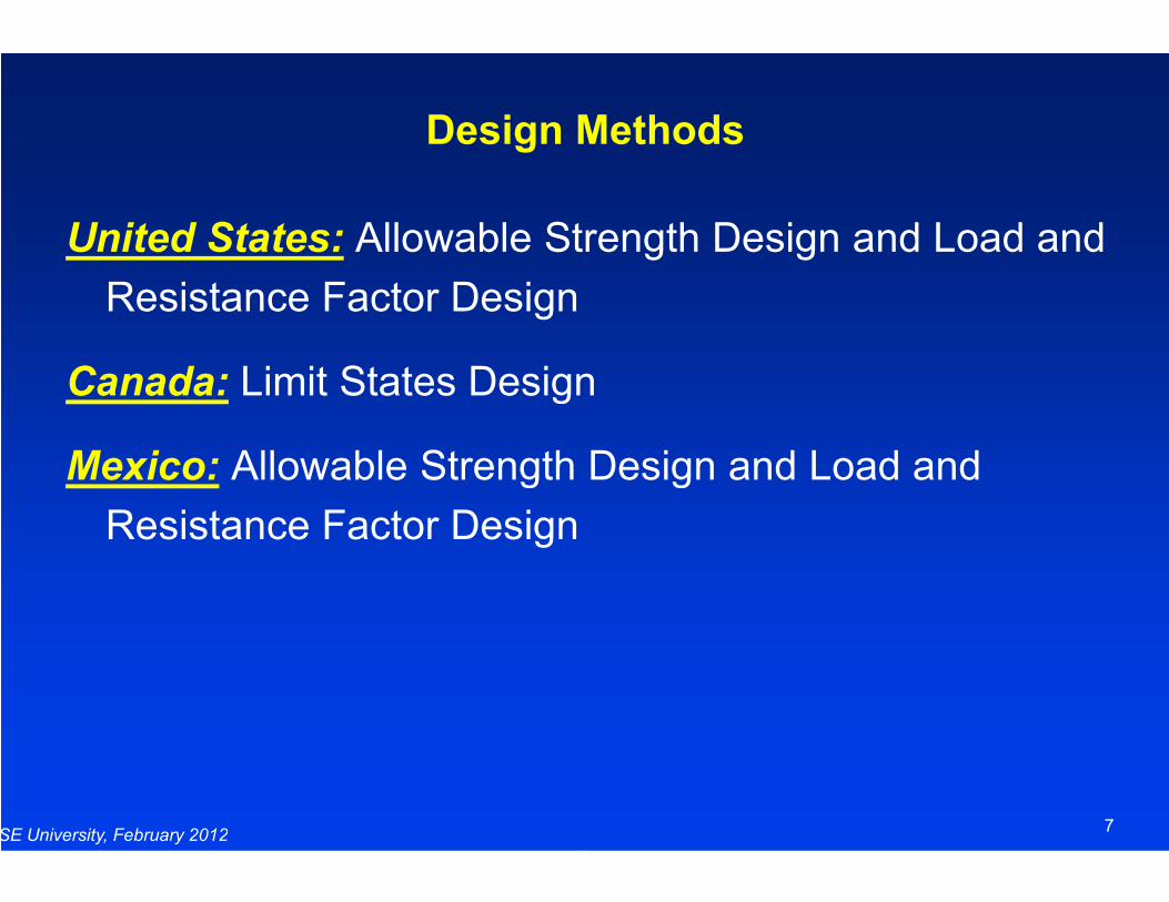
Design Methods
United States: Allowable Strength Design and Load and
Resistance Factor Design
Canada: Limit States Design
Mexico: Allowable Strength Design and Load and
SE University, February 2012
Mexico: Allowable Strength Design and Load and
Resistance Factor Design
Design Methods
Allowable Strength Design and Load and
Limit States Design
Allowable Strength Design and Load and
7
Allowable Strength Design and Load and
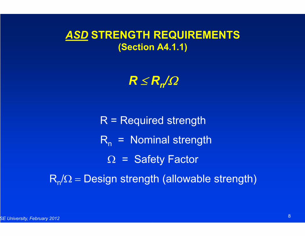
ASD STRENGTH REQUIREMENTS(Section A4.1.1)
R ≤ ≤ ≤ ≤ R
R = Required strength
SE University, February 2012
R = Required strength
Rn = Nominal strength
Ω = Safety Factor
Rn/Ω = Design strength (allowable strength)
STRENGTH REQUIREMENTS(Section A4.1.1)
Rn/ΩΩΩΩ
R = Required strength
8
R = Required strength
= Nominal strength
= Safety Factor
Design strength (allowable strength)
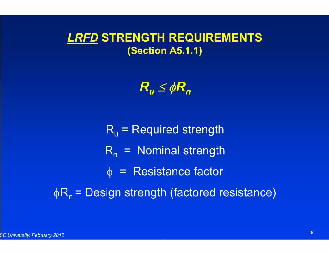
LRFD STRENGTH REQUIREMENTS(Section A5.1.1)
Ru ≤ φ≤ φ≤ φ≤ φ
R = Required strength
SE University, February 2012
Ru = Required strength
Rn = Nominal strength
φ = Resistance factor
φRn = Design strength (factored resistance)
STRENGTH REQUIREMENTS(Section A5.1.1)
≤ φ≤ φ≤ φ≤ φRn
= Required strength
9
= Required strength
= Nominal strength
= Resistance factor
= Design strength (factored resistance)
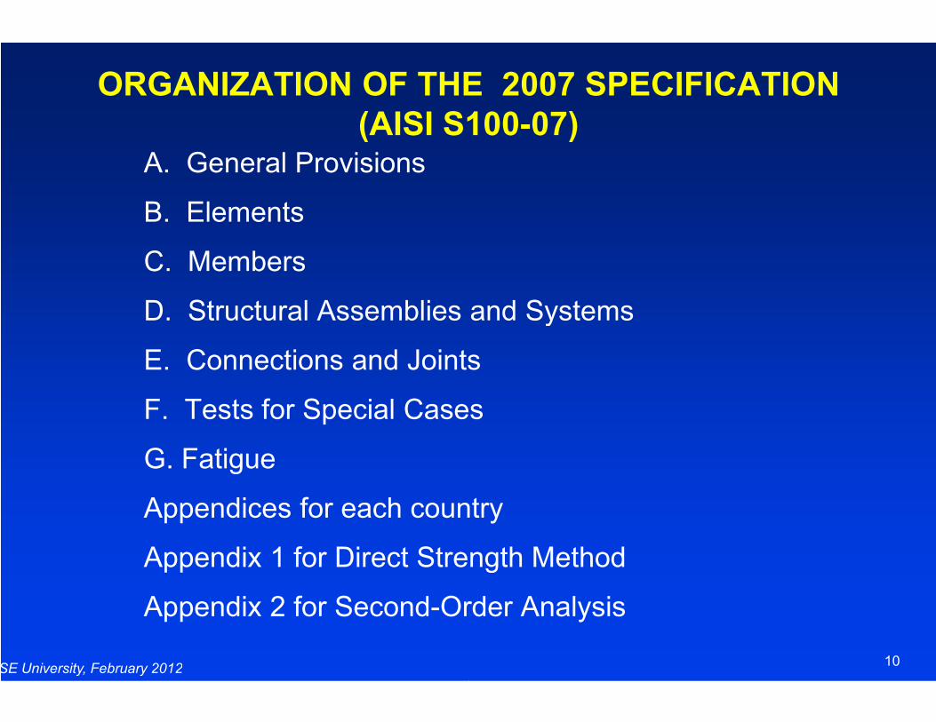
ORGANIZATION OF THE 2007 SPECIFICATION
(AISI S100A. General Provisions
B. Elements
C. Members
D. Structural Assemblies and Systems
E. Connections and Joints
SE University, February 2012
E. Connections and Joints
F. Tests for Special Cases
G. Fatigue
Appendices for each country
Appendix 1 for Direct Strength Method
Appendix 2 for Second-Order Analysis
ORGANIZATION OF THE 2007 SPECIFICATION
(AISI S100-07)
D. Structural Assemblies and Systems
E. Connections and Joints
10
E. Connections and Joints
F. Tests for Special Cases
Appendices for each country
Appendix 1 for Direct Strength Method
Order Analysis
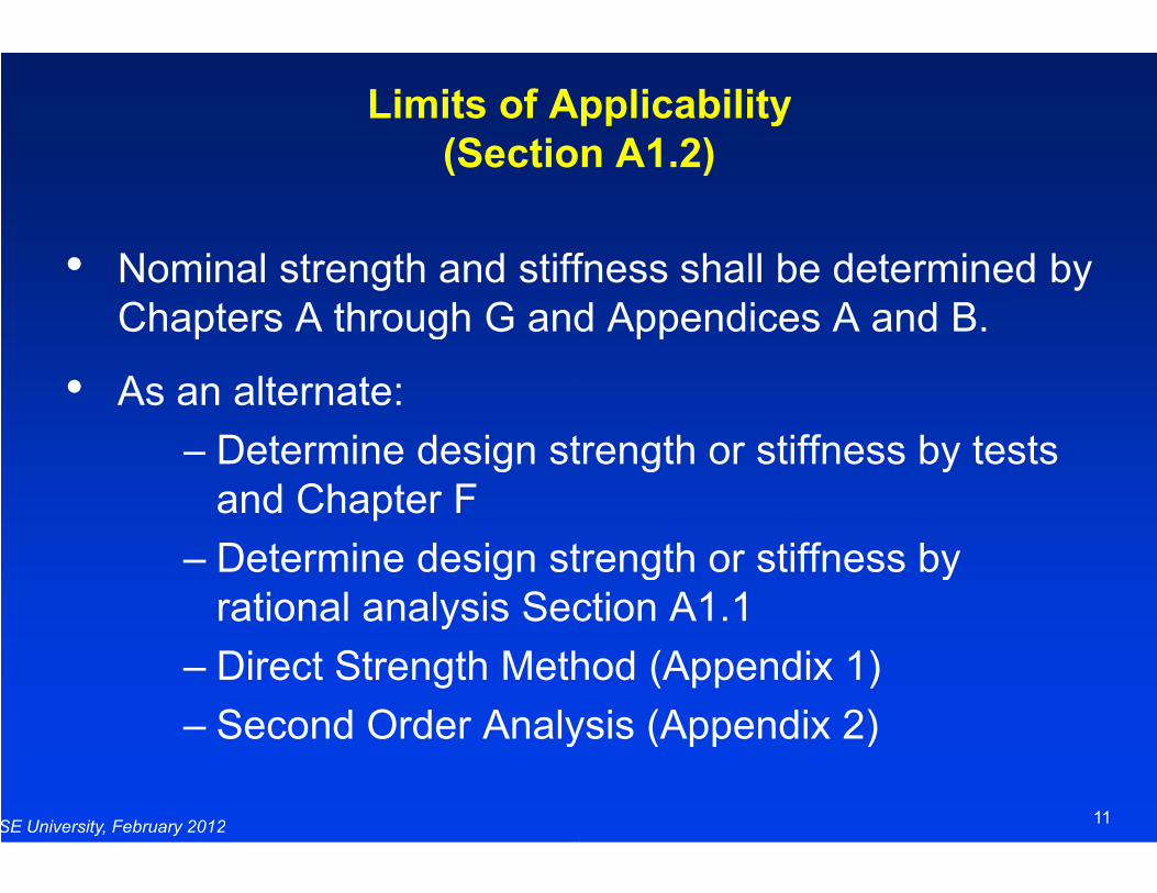
Limits of Applicability
(Section A1.2)
• Nominal strength and stiffness shall be determined by Chapters A through G and Appendices A and B.
• As an alternate:
– Determine design strength or stiffness by tests
SE University, February 2012
– Determine design strength or stiffness by tests and Chapter F
– Determine design strength or stiffness by rational analysis Section A1.1
– Direct Strength Method (Appendix 1)
– Second Order Analysis (Appendix 2)
Limits of Applicability
(Section A1.2)
Nominal strength and stiffness shall be determined by Chapters A through G and Appendices A and B.
Determine design strength or stiffness by tests
11
Determine design strength or stiffness by tests
Determine design strength or stiffness by rational analysis Section A1.1
Direct Strength Method (Appendix 1)
Second Order Analysis (Appendix 2)
STEEL MATERIALS AND PRODUCTS(Section A1.1)
The Specification Covers
• Steel:
SE University, February 2012
• Steel Products:
• Members:
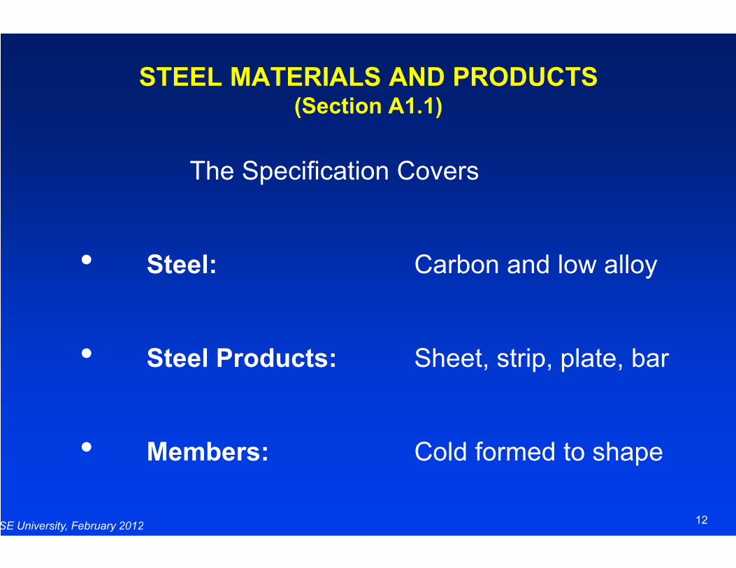
STEEL MATERIALS AND PRODUCTS(Section A1.1)
The Specification Covers
Carbon and low alloy
12
Sheet, strip, plate, bar
Cold formed to shape

TYPICAL APPROVED STEELS(Section A2.1)
16 Approved Steels in Section A2.1.
ASTM A653 Steel Sheet, Zinc Coated (Galvanized) or Zinc-Iron Alloy-Coated (Galvannealed) by the HotProcess
SE University, February 2012
ProcessFy = 33 to 50 ksi Fu = 45 to 70 ksiFy = 80 ksi Fu = 82 ksi
ASTM A792 Steel Sheet, 55% AluminumCoated by the Hot-Dip ProcessFy = 33 to 50 ksi Fu = 45 to 70 ksiFy = 80 ksi Fu = 82 ksi
TYPICAL APPROVED STEELS(Section A2.1)
16 Approved Steels in Section A2.1.
Steel Sheet, Zinc Coated (Galvanized) or Coated (Galvannealed) by the Hot-Dip
13
= 45 to 70 ksi= 82 ksi
Steel Sheet, 55% Aluminum-Zinc Alloy-Dip Process
= 45 to 70 ksi= 82 ksi

TYPICAL APPROVED STEELS(Section A2.1)
ASTM A1011 Steel Sheet, HotStructural, High Strength LowFormability
SE University, February 2012
ASTM A1003 Steel Sheet, Carbon, MetallicNonmetallic-Coated for Cold Formed Framing Members
(Replaced A653 for framing members)
TYPICAL APPROVED STEELS(Section A2.1)
Steel Sheet, Hot-Rolled, Carbon, Structural, High Strength Low-Alloy with improved
14
Steel Sheet, Carbon, Metallic- and Coated for Cold Formed Framing
(Replaced A653 for framing members)
TYPICAL APPROVED STEELS(Section A2.1)
ASTM A1039 Steel Sheet, HotCommercial and Structural, Produced by TwinCasting Process.
Grades: 40, 50, 55, 60, 70, and 80.
SE University, February 2012
Grades: 40, 50, 55, 60, 70, and 80.
Steel thicknesses less than 0.064”, Fmeet ductility requirements of 10% Section A2.3.1. Thus Section A2.3.2 applies.
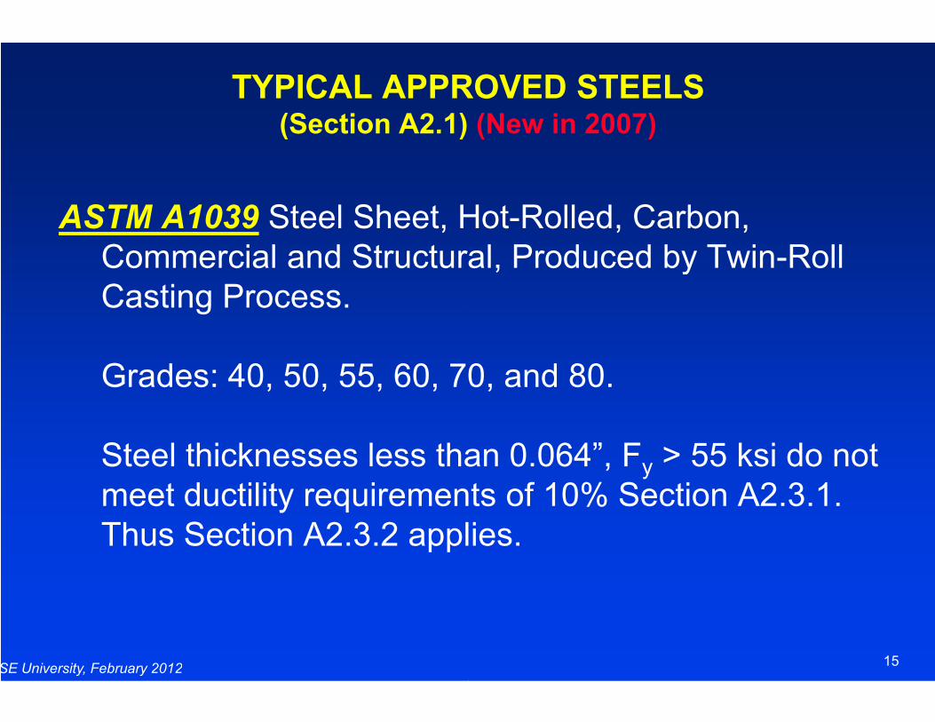
TYPICAL APPROVED STEELS(Section A2.1) (New in 2007)
Steel Sheet, Hot-Rolled, Carbon, Commercial and Structural, Produced by Twin-Roll
Grades: 40, 50, 55, 60, 70, and 80.
15
Grades: 40, 50, 55, 60, 70, and 80.
Steel thicknesses less than 0.064”, Fy > 55 ksi do not meet ductility requirements of 10% Section A2.3.1. Thus Section A2.3.2 applies.
OTHER STRUCTURAL QUALITY STEELS(Section A2.2)
Maximum Thickness
Published Material Specification with Specified
SE University, February 2012
Published Material Specification with Specified Mechanical and Chemical Properties
Minimum Ductility Requirements of Section A2.3
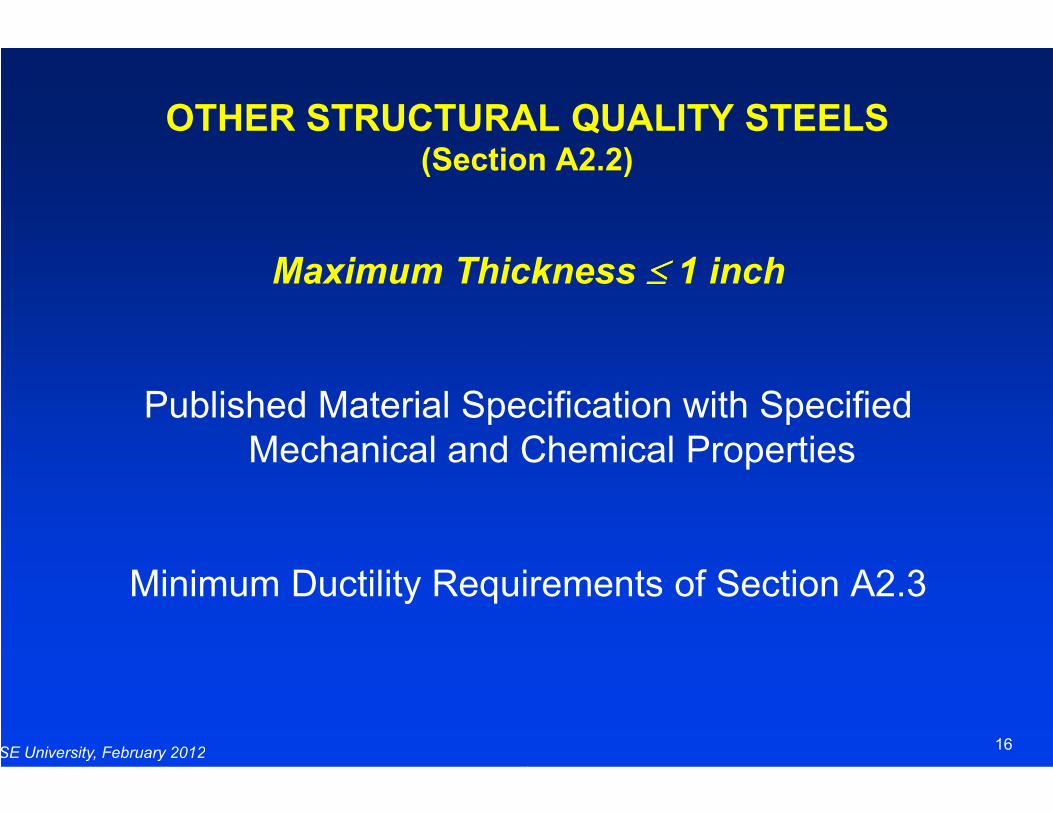
OTHER STRUCTURAL QUALITY STEELS(Section A2.2)
Maximum Thickness ≤≤≤≤ 1 inch
Published Material Specification with Specified
16
Published Material Specification with Specified Mechanical and Chemical Properties
Minimum Ductility Requirements of Section A2.3
REQUIRED DUCTILITY(Section A2.3.1)
Fu/Fy ≥≥≥≥
SE University, February 2012
Elongation ≥ 10% (two
≥ 7% (eight
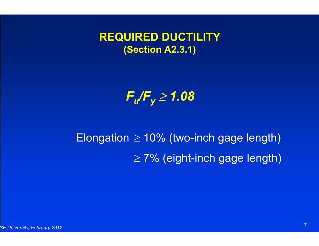
REQUIRED DUCTILITY(Section A2.3.1)
≥≥≥≥ 1.08
17
10% (two-inch gage length)
7% (eight-inch gage length)
LOW DUCTILITY STEELS(Section A2.3.2)
ASTM A653, A792, A875 and A1008, Grade 80 material
May be used for deck and panel profiles
SE University, February 2012
Limits on Fy and Fu
Alternatively, suitability shall be determined by tests.
Exceptions: Multi-web configurations (flexural strength)
Closed box sections (compression strength)
LOW DUCTILITY STEELS(Section A2.3.2)
ASTM A653, A792, A875 and A1008, Grade 80 material
used for deck and panel profiles
18
Alternatively, suitability shall be determined by tests.
web configurations (flexural strength)
Closed box sections (compression strength)
BUCKLING MODES
(Overall & Cross Section)
SE University, February 2012
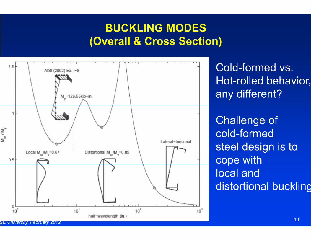
BUCKLING MODES
(Overall & Cross Section)
Cold-formed vs.Hot-rolled behavior,any different?
Challenge of
19
Challenge of cold-formedsteel design is to cope with local and distortional buckling.
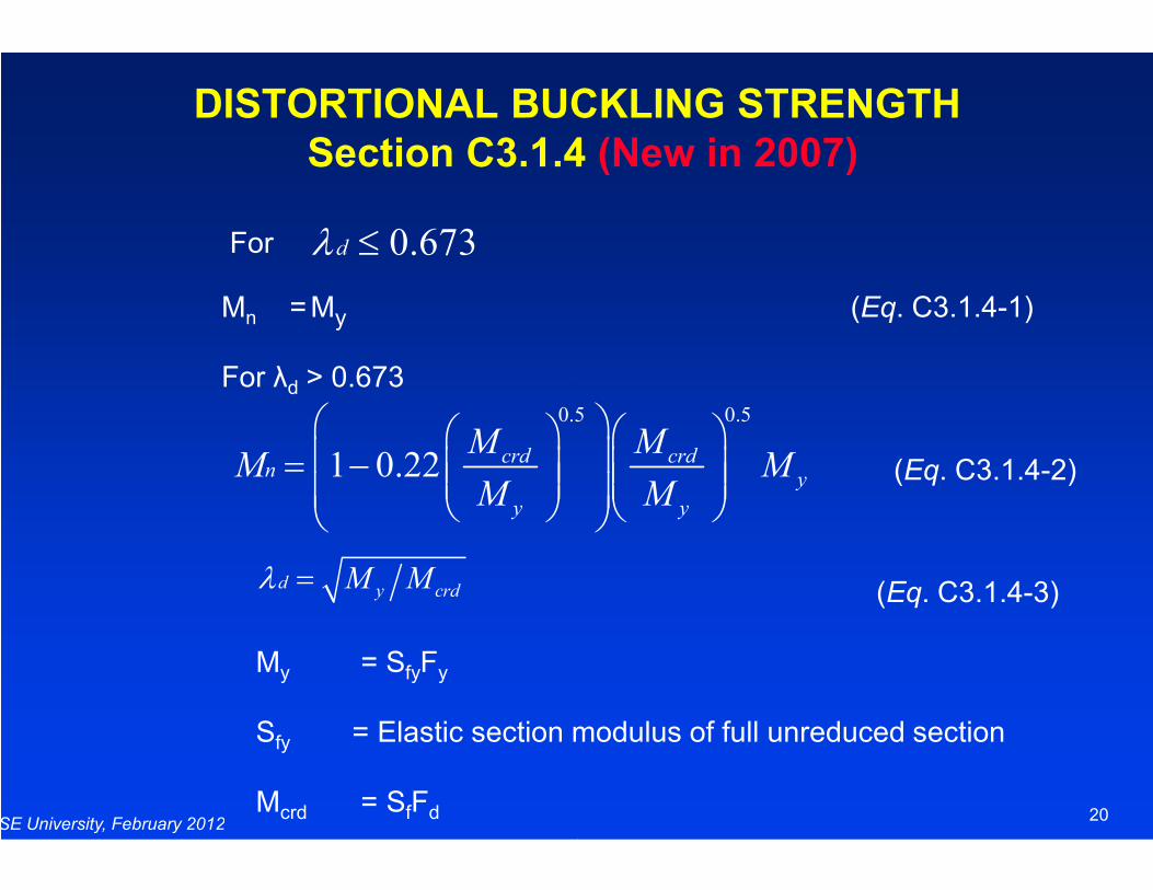
DISTORTIONAL BUCKLING STRENGTH
Section C3.1.4
0.673dλ ≤
0.5 0.5
1 0.22 crd crdM MM M
= −
For
Mn =My
For λd > 0.673
SE University, February 2012
1 0.22 crd crdn
y y
M MM M
M M
= −
d y crdM Mλ =
My = SfyFy
Sfy = Elastic section modulus of full unreduced section
Mcrd = SfFd
DISTORTIONAL BUCKLING STRENGTH
Section C3.1.4 (New in 2007)
0.5 0.5
crd crdM MM M
(Eq. C3.1.4-1)
20
crd crdy
y y
M MM M
M M
(Eq. C3.1.4-2)
Elastic section modulus of full unreduced section
(Eq. C3.1.4-3)
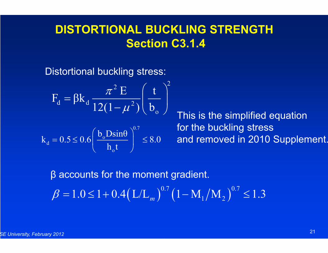
DISTORTIONAL BUCKLING STRENGTH
Section C3.1.4
Distortional buckling stress:
2
d d 2
o
E tF βk
12(1 ) b
πµ
= −
0.7
SE University, February 2012
β accounts for the moment gradient.
0.7
od
o
b Dsinθk 0.5 0.6 8.0
h t
= ≤ ≤
( )0.7 0.71.0 1 0.4 L/L 1 M M 1.3mβ = ≤ + − ≤
DISTORTIONAL BUCKLING STRENGTH
Section C3.1.4
Distortional buckling stress:
This is the simplified equation for the buckling stress
2
o
E t
12(1 ) b
21
accounts for the moment gradient.
for the buckling stress and removed in 2010 Supplement.
( )0.7 0.7
1 21.0 1 0.4 L/L 1 M M 1.3= ≤ + − ≤
DISTORTIONAL BUCKLING STRENGTH
Section C3.1.4
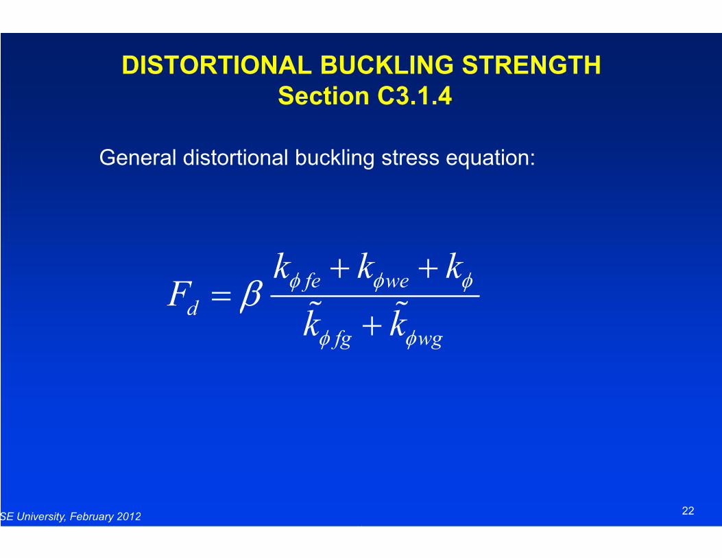
General distortional buckling stress equation:
fe wek k kF
φ φ φβ+ +
=
SE University, February 2012
fe we
d
fg wg
k k kF
k k
φ φ φ
φ φ
β+ +
=% %
DISTORTIONAL BUCKLING STRENGTH
Section C3.1.4
General distortional buckling stress equation:
fe wek k kφ φ φ+ +
22
fe we
fg wg
k k k
k k
φ φ φ
φ φ
+ +
+% %
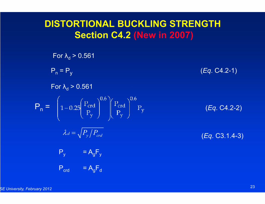
DISTORTIONAL BUCKLING STRENGTH
Section C4.2
For λd > 0.561
Pn = Py
For λd > 0.561
P =
SE University, February 2012
d y crdP Pλ =
Py = AgFy
Pcrd = AgFd
Pn =
DISTORTIONAL BUCKLING STRENGTH
Section C4.2 (New in 2007)
(Eq. C4.2-1)
23
(Eq. C4.2-2)
(Eq. C3.1.4-3)
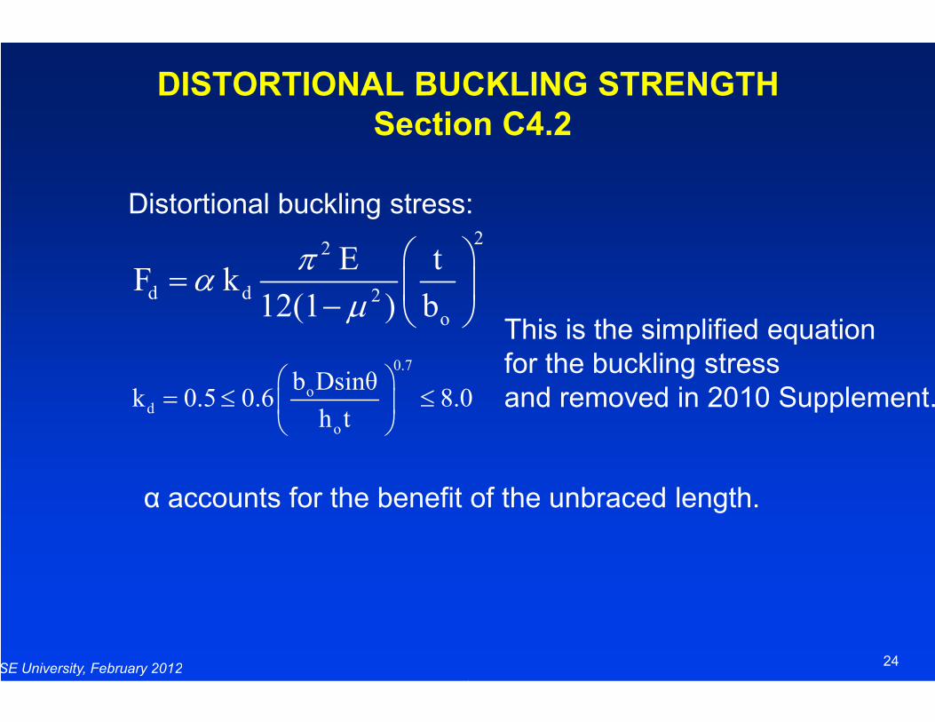
DISTORTIONAL BUCKLING STRENGTH
Section C4.2
Distortional buckling stress:
2
d d 2
o
E tF k
12(1 ) b
πα
µ
= − 0.7
SE University, February 2012
α accounts for the benefit of the unbraced length.
0.7
od
o
b Dsinθk 0.5 0.6 8.0
h t
= ≤ ≤
DISTORTIONAL BUCKLING STRENGTH
Section C4.2
Distortional buckling stress:2
o
E t
12(1 ) b
This is the simplified equation
for the buckling stress
24
accounts for the benefit of the unbraced length.
k 0.5 0.6 8.0
for the buckling stress and removed in 2010 Supplement.
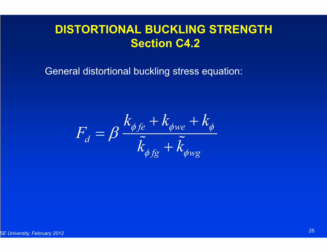
DISTORTIONAL BUCKLING STRENGTH
Section C4.2
General distortional buckling stress equation:
fe wek k kF
φ φ φβ+ +
=
SE University, February 2012
fe we
d
fg wg
k k kF
k k
φ φ φ
φ φ
β+ +
=% %
DISTORTIONAL BUCKLING STRENGTH
Section C4.2
General distortional buckling stress equation:
fe wek k kφ φ φ+ +
25
fe we
fg wg
k k k
k k
φ φ φ
φ φ
+ +
+% %
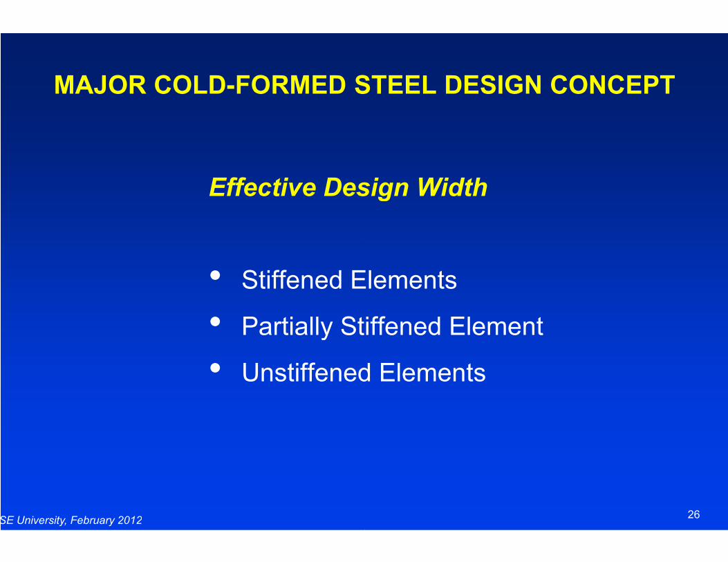
MAJOR COLD-FORMED STEEL DESIGN CONCEPT
Effective Design Width
• Stiffened Elements
SE University, February 2012
• Stiffened Elements
• Partially Stiffened Element
• Unstiffened Elements
FORMED STEEL DESIGN CONCEPT
Effective Design Width
Stiffened Elements
26
Stiffened Elements
Partially Stiffened Element
Unstiffened Elements
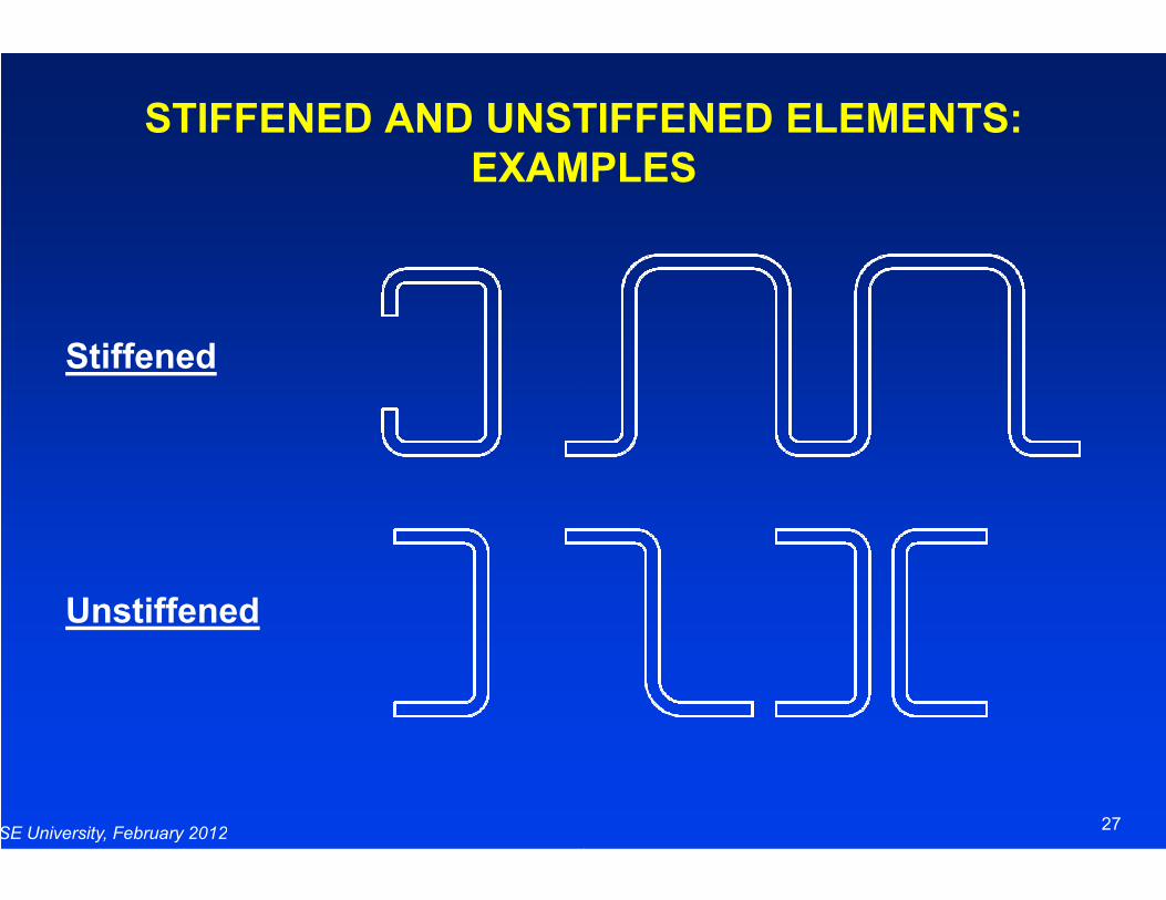
STIFFENED AND UNSTIFFENED ELEMENTS:
EXAMPLES
Stiffened
SE University, February 2012
Unstiffened
STIFFENED AND UNSTIFFENED ELEMENTS:
EXAMPLES
27
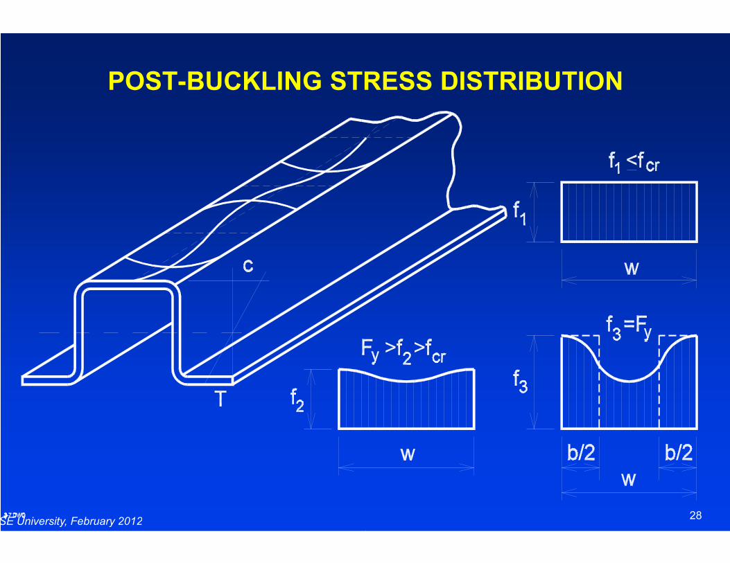
POST-BUCKLING STRESS DISTRIBUTION
SE University, February 2012
BUCKLING STRESS DISTRIBUTION
28

EFFECTIVE WIDTH CONCEPT
SE University, February 2012
o
w
fdx = b∫
EFFECTIVE WIDTH CONCEPT
29
fdx = bfmax
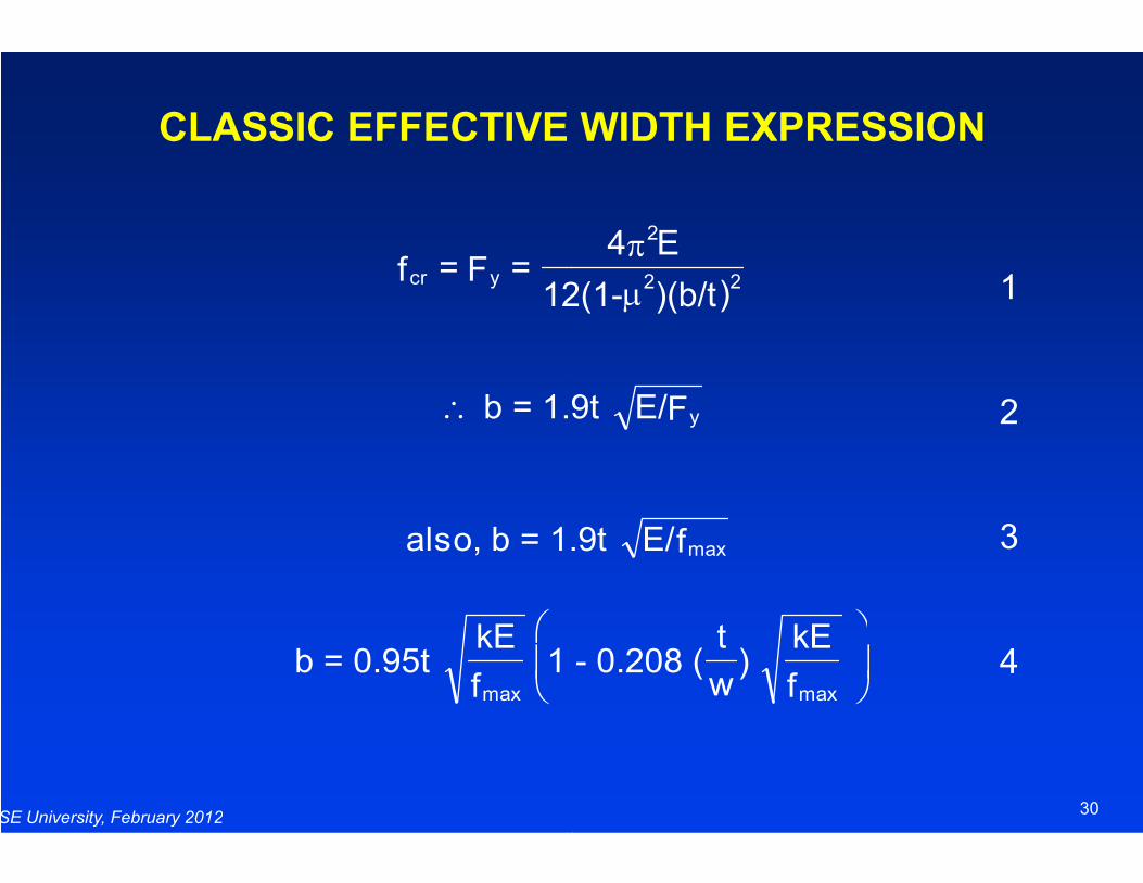
CLASSIC EFFECTIVE WIDTH EXPRESSION
cr yf = F = 12(1-
∴ b = 1.9t
SE University, February 2012
b = 0.95t kE
f 1 - 0.208
max
also, b = 1.9t
CLASSIC EFFECTIVE WIDTH EXPRESSION
1
2
2
2 2
4 E
12(1- )(b/t)
π
µ
= 1.9t E/Fy
30
3
41 - 0.208 (t
w)
kE
f
max
= 1.9t E/fmax
BASIC EFFECTIVE WIDTH EXPRESSION(Section B2.1)
b = w when
w when = b ρ
0.22
SE University, February 2012Used in all cases of effective width considerations
= λ
0.22 - (1 = ρ
12(1 k = F cr
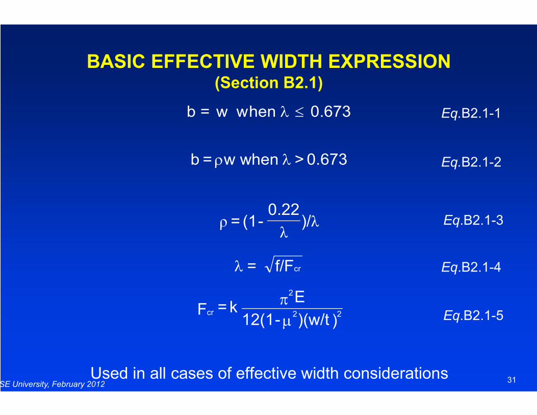
BASIC EFFECTIVE WIDTH EXPRESSION(Section B2.1)
Eq.B2.1-1
Eq.B2.1-2
hen 0.673λ ≤
0.673 > w when λ
0.22
31
Eq.B2.1-3
Eq.B2.1-4
Eq.B2.1-5
Used in all cases of effective width considerations
f/Fcr
)/0.22
λλ
))(w/t-12(1
E22
2
µπ
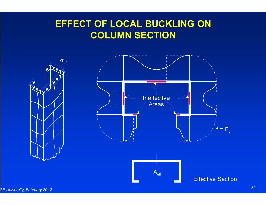
EFFECT OF LOCAL BUCKLING ON
COLUMN SECTION
σult
SE University, February 2012
EFFECT OF LOCAL BUCKLING ON
COLUMN SECTION
IneffecitveAreas
32
f = Fy
Aeff
Effective Section
Areas
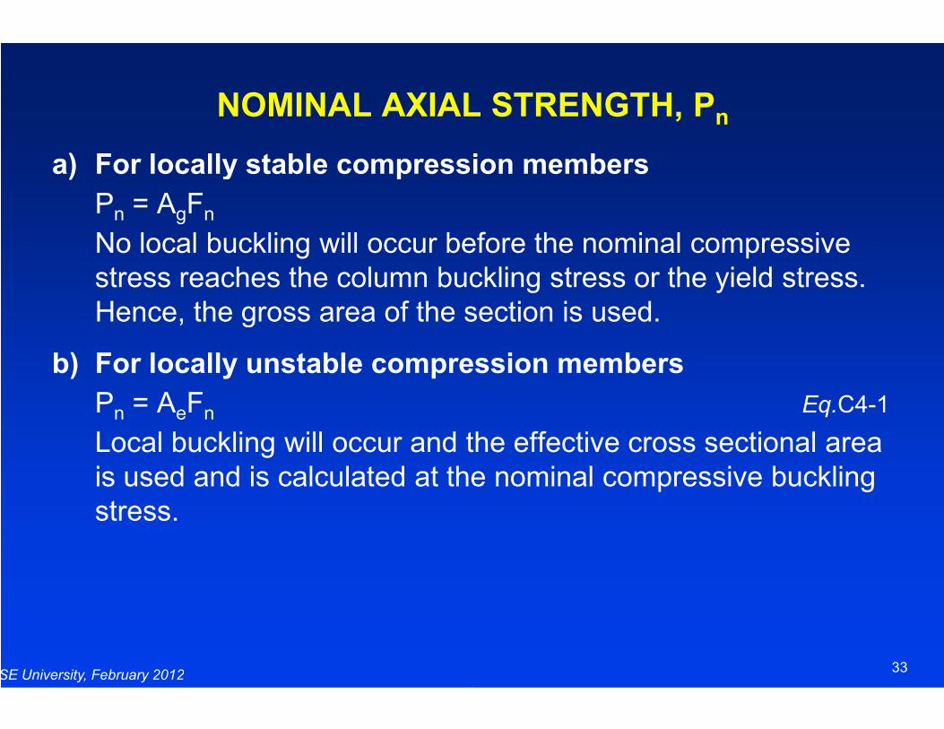
NOMINAL AXIAL STRENGTH, P
a) For locally stable compression members
Pn = AgFn
No local buckling will occur before the nominal compressive stress reaches the column buckling stress or the yield stress. Hence, the gross area of the section is used.
b) For locally unstable compression members
SE University, February 2012
b) For locally unstable compression members
Pn = AeFn
Local buckling will occur and the effective cross sectional area is used and is calculated at the nominal compressive buckling stress.
NOMINAL AXIAL STRENGTH, Pn
For locally stable compression members
No local buckling will occur before the nominal compressive stress reaches the column buckling stress or the yield stress. Hence, the gross area of the section is used.
For locally unstable compression members
33
For locally unstable compression members
Eq.C4-1
Local buckling will occur and the effective cross sectional area is used and is calculated at the nominal compressive buckling
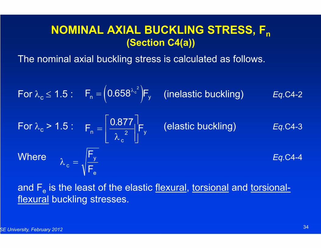
NOMINAL AXIAL BUCKLING STRESS, F(Section C4(a))
The nominal axial buckling stress is calculated as follows.
For λc ≤ 1.5 :
For λ > 1.5 : F =
0 877.F
( )Fn = 0 6582
. λc Fy
SE University, February 2012
For λc > 1.5 :
Where
and Fe is the least of the elastic flexuralflexural buckling stresses.
Fn =
0 8772
.
λ c
yF
λ c
y
e
F
F=
NOMINAL AXIAL BUCKLING STRESS, Fn(Section C4(a))
The nominal axial buckling stress is calculated as follows.
(inelastic buckling) Eq.C4-2
(elastic buckling) Eq.C4-3
34
(elastic buckling) Eq.C4-3
Eq.C4-4
flexural, torsional and torsional-
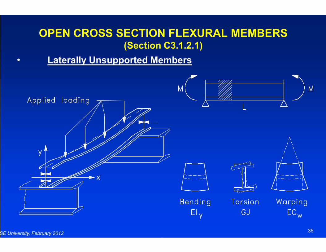
OPEN CROSS SECTION FLEXURAL MEMBERS (Section C3.1.2.1)
• Laterally Unsupported Members
SE University, February 2012
OPEN CROSS SECTION FLEXURAL MEMBERS (Section C3.1.2.1)
Laterally Unsupported Members
35
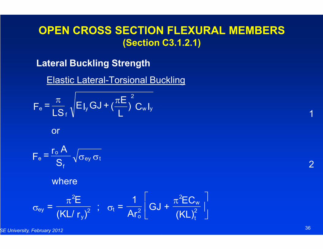
OPEN CROSS SECTION FLEXURAL MEMBERS(Section C3.1.2.1)
Lateral Buckling Strength
Elastic Lateral-Torsional Buckling
IC)L
E( + GJIE
LS = F yw
2
yf
e
ππ
SE University, February 2012
or
where
S
A r = F tey
f
oe σσ
ey
2
2y
to2 =
E
(KL/ r ) ; =
1
Ar GJ + σ
πσ
OPEN CROSS SECTION FLEXURAL MEMBERS(Section C3.1.2.1)
Torsional Buckling
1
36
2
2
w
t
2GJ + EC
(KL)
π
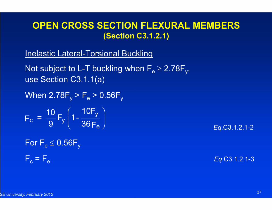
Inelastic Lateral-Torsional Buckling
Not subject to L-T buckling when F
use Section C3.1.1(a)
When 2.78Fy > Fe > 0.56Fy
OPEN CROSS SECTION FLEXURAL MEMBERS (Section C3.1.2.1)
SE University, February 2012
For Fe ≤ 0.56Fy
Fc = Fe
F36
F10 - 1 F
9
10 = F
e
yyc
Torsional Buckling
T buckling when Fe ≥ 2.78Fy,
OPEN CROSS SECTION FLEXURAL MEMBERS (Section C3.1.2.1)
37
Eq.C3.1.2.1-2
e Eq.C3.1.2.1-3
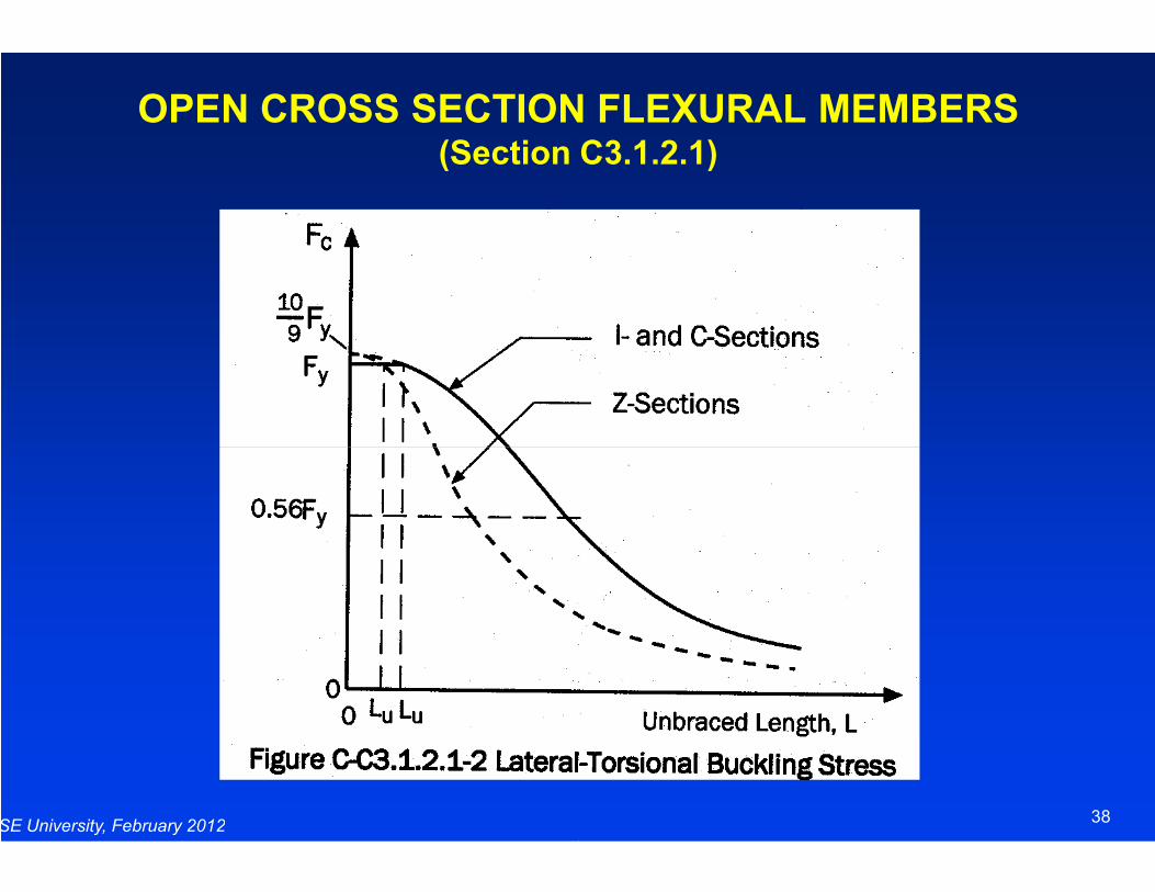
OPEN CROSS SECTION FLEXURAL MEMBERS(Section C3.1.2.1)
SE University, February 2012
OPEN CROSS SECTION FLEXURAL MEMBERS(Section C3.1.2.1)
38
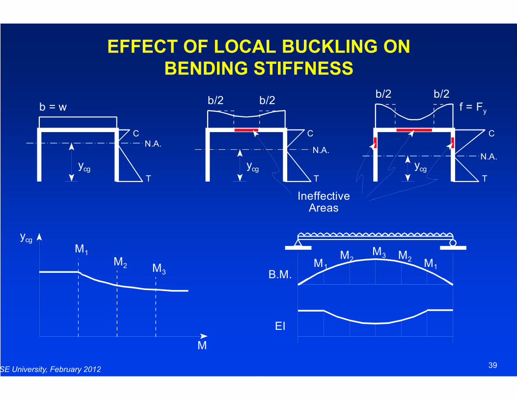
EFFECT OF LOCAL BUCKLING ON
BENDING STIFFNESS
b = wb/2
CN.A.
ycg ycg
T
SE University, February 2012
ycg
M3
M2
M1
M
EFFECT OF LOCAL BUCKLING ON
BENDING STIFFNESS
b/2f = Fy
C
T
C
T
N.A.N.A.
ycg
b/2b/2
Ineffective
39
M2 M1
M3 M2M1
B.M.
EI
IneffectiveAreas
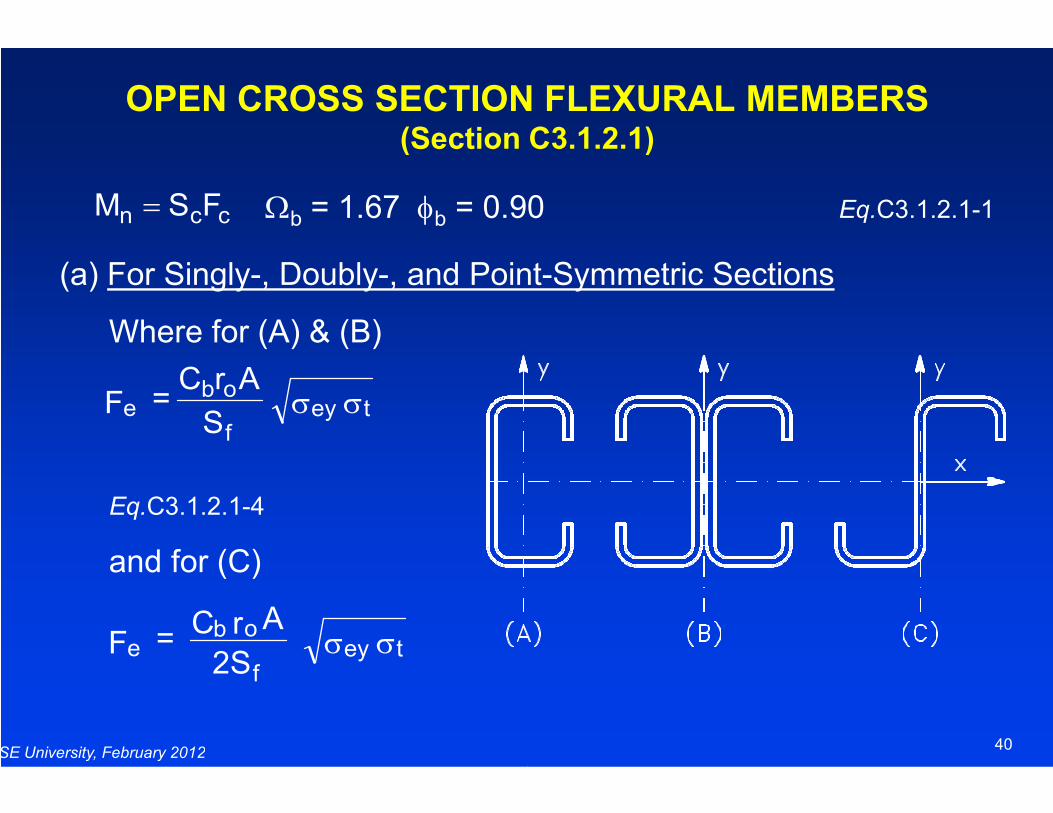
OPEN CROSS SECTION FLEXURAL MEMBERS (Section C3.1.2.1)
Ωb = 1.67 φb = 0.90
(a) For Singly-, Doubly-, and Point
Where for (A) & (B)
S
ArC = F tey
obe σσ
ccn FSM =
SE University, February 2012
Eq.C3.1.2.1-4
and for (C)
S
= F teyf
e σσ
2S
Ar C = F tey
f
obe σσ
OPEN CROSS SECTION FLEXURAL MEMBERS (Section C3.1.2.1)
= 0.90 Eq.C3.1.2.1-1
, and Point-Symmetric Sections
40
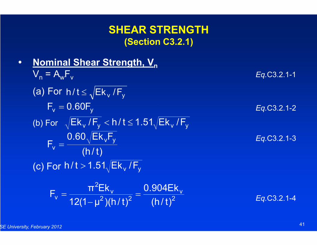
SHEAR STRENGTH(Section C3.2.1)
Nominal Shear Strength, VnVn = AwFv
(a) For
(b) For
yv F/Ekt/h ≤
yv F60.0F =
yv Ek51.1t/hF/Ek ≤<
SE University, February 2012
(b) For
(c) For
yv Ek51.1t/hF/Ek ≤<
)t/h(
FEk60.0F
yvv =
yv F/Ek51.1t/h >
22v
2
vh(
904.0
)t/h)(µ1(12
EkπF =
−=
SHEAR STRENGTH(Section C3.2.1)
Eq.C3.2.1-1
Eq.C3.2.1-2
yv F/Ek
41
Eq.C3.2.1-3
Eq.C3.2.1-4
yv F/Ek
2v
)t/h
Ek904

WEB CRIPPLING (Section C3.4)
Basic Web Crippling Equation
+
−=
t
NC1
t
RC1sinFCtP NRy
2n θ
SE University, February 2012
Web crippling coefficients C, CR, Cappropriate tables for fastened or unfastened
R/t = inside bend radius ratio N/t = bearing length ratio h/t = web slenderness ratio
WEB CRIPPLING (Section C3.4)
Eq.C3.4.1-1
−
t
hC1
t
Nh
42
, CN, and Ch are given in the unfastened to the support.
R/t = inside bend radius ratio N/t = bearing length ratio
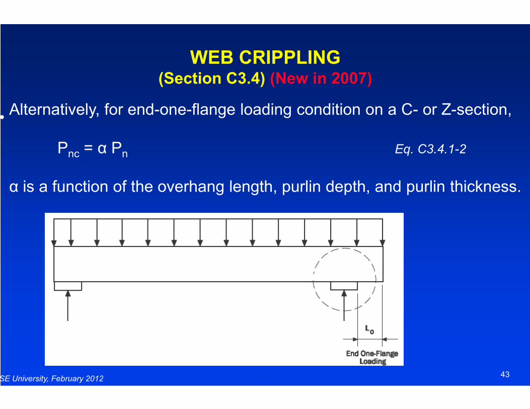
WEB CRIPPLING (Section C3.4)
• Alternatively, for end-one-flange loading condition on a C
Pnc = α Pn
α is a function of the overhang length, purlin depth, and purlin thickness.
SE University, February 2012
WEB CRIPPLING (Section C3.4) (New in 2007)
flange loading condition on a C- or Z-section,
Eq. C3.4.1-2
is a function of the overhang length, purlin depth, and purlin thickness.
43
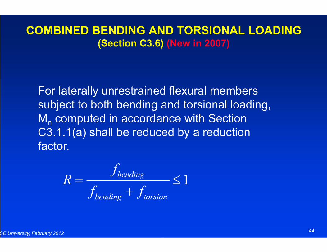
COMBINED BENDING AND TORSIONAL LOADING (Section C3.6)
For laterally unrestrained flexural members subject to both bending and torsional loading, Mn computed in accordance with Section C3.1.1(a) shall be reduced by a reduction
SE University, February 2012
n
C3.1.1(a) shall be reduced by a reduction factor.
bending
bending torsion
fR
f f= ≤
+
COMBINED BENDING AND TORSIONAL LOADING (Section C3.6) (New in 2007)
For laterally unrestrained flexural members subject to both bending and torsional loading,
computed in accordance with Section C3.1.1(a) shall be reduced by a reduction
44
C3.1.1(a) shall be reduced by a reduction
1bending torsion
= ≤
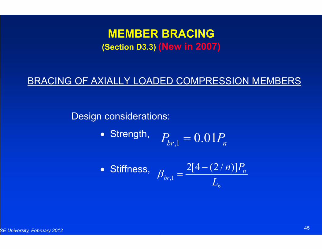
MEMBER BRACING(Section D3.3) (New in 2007)
BRACING OF AXIALLY LOADED COMPRESSION MEMBERS
Design considerations:
SE University, February 2012
• Strength,
• Stiffness,
P P
β
MEMBER BRACING(New in 2007)
BRACING OF AXIALLY LOADED COMPRESSION MEMBERS
Design considerations:
45
,1 0.01br nP P=
,1
2[4 (2 / )] nbr
b
n P
Lβ
−=
Standards for Cold
Light-Frame Construction
COLD-FORMED STEEL LIGHT
(Section D4)
SE University, February 2012
Light-Frame Construction
Standards for Cold-Formed Steel
Frame Construction
FORMED STEEL LIGHT-FRAME CONSTRUCTION
(Section D4) (New in 2007)
46
Frame Construction
AISI COFS Mission
• To eliminate regulatory barriers and increase the reliability and cost competitiveness of cold-formed steel framing in residential and light commercial building construction through improved design and installation standards.
SE University, February 2012
AISI COFS Mission
To eliminate regulatory barriers and increase the reliability and formed steel framing in residential
and light commercial building construction through improved standards.
47
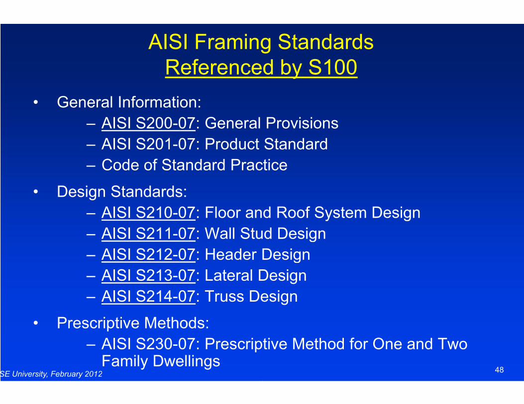
AISI Framing StandardsReferenced by S100
• General Information:
– AISI S200-07: General Provisions
– AISI S201-07: Product Standard
– Code of Standard Practice
• Design Standards:
SE University, February 2012
– AISI S210-07: Floor and Roof System Design
– AISI S211-07: Wall Stud Design
– AISI S212-07: Header Design
– AISI S213-07: Lateral Design
– AISI S214-07: Truss Design
• Prescriptive Methods:
– AISI S230-07: Prescriptive Method for One and Two Family Dwellings
AISI Framing StandardsReferenced by S100
: General Provisions
07: Product Standard
Code of Standard Practice
48
: Floor and Roof System Design
: Wall Stud Design
: Header Design
: Lateral Design
: Truss Design
07: Prescriptive Method for One and Two
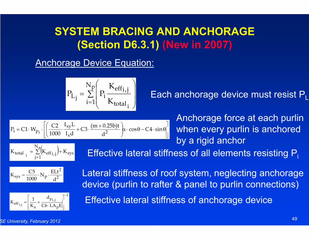
SYSTEM BRACING AND ANCHORAGE
(Section D6.3.1)
∑=
=
p
i
j
N
1i total
j,ieffiLK
KPP
Anchorage Device Equation:
Each anchorage device must resist P
SE University, February 2012
⋅−θ⋅α
+⋅+⋅⋅⋅= 4Ccos
d
t)b25.0m(3C
dI
LI
1000
2CW1CP
2x
xypi i
( ) sys
N
1jj,iefftotal KKK
a
i += ∑
=
2
2
psysd
ELtN
1000
5CK ⋅⋅=
1
p
p
aeff
ELA6C
d
K
1K
j,i
ji,
−
⋅+=
Effective lateral stiffness of all elements resisting P
Lateral stiffness of roof system, neglecting anchoragedevice (purlin to rafter & panel to purlin connections)
Effective lateral stiffness of anchorage device
SYSTEM BRACING AND ANCHORAGE
(Section D6.3.1) (New in 2007)
Each anchorage device must resist PL
Anchorage force at each purlin
49
θsin
Effective lateral stiffness of all elements resisting Pi
Lateral stiffness of roof system, neglecting anchoragedevice (purlin to rafter & panel to purlin connections)
Effective lateral stiffness of anchorage device
Anchorage force at each purlinwhen every purlin is anchoredby a rigid anchor
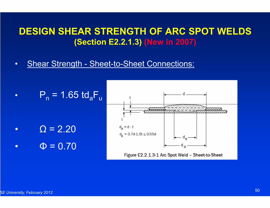
DESIGN SHEAR STRENGTH OF ARC SPOT WELDS(Section E2.2.1.3)
• Shear Strength - Sheet-to-Sheet Connections:
• Pn = 1.65 tdaFu
SE University, February 2012
• Ω = 2.20
• Φ = 0.70
DESIGN SHEAR STRENGTH OF ARC SPOT WELDS(Section E2.2.1.3) (New in 2007)
Sheet Connections:
50
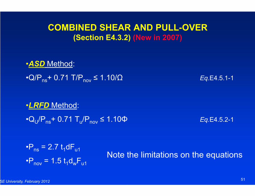
COMBINED SHEAR AND PULL(Section E4.3.2)
•ASD Method:
•Q/Pns+ 0.71 T/Pnov ≤ 1.10/Ω
SE University, February 2012
•LRFD Method:
•QU/Pns+ 0.71 Tu/Pnov ≤ 1.10Φ
•Pns = 2.7 t1dFu1
•Pnov = 1.5 t1dwFu1
Note the limitations on the equations
COMBINED SHEAR AND PULL-OVER(Section E4.3.2) (New in 2007)
Eq.E4.5.1-1
51
Eq.E4.5.2-1
Note the limitations on the equations
Cold-Formed Steel Design, 4th Edition
The book expanded on to reflect:2007 North American 2007 North American Framing Standards
SE University, February 2012
and other newly published standards and documents.
Ordering information:www.ccfssonline.org
Price: $110 plus shipping
Formed Steel Design, 4th Edition
he book has been thoroughly updated andexpanded on to reflect:
North American Specification2007 North American Framing Standards
52
other newly published standards documents.
Ordering information:www.ccfssonline.org
Price: $110 plus shipping
Wei-Wen Yu
Center for Cold-Formed Steel Structure
SE University, February 2012
Center for Cold-Formed Steel Structure
[email protected], 573
Wen Yu
Formed Steel Structure
53
Formed Steel Structure
[email protected], 573-341-4481

QUESTIONS?
SE University, February 2012
QUESTIONS?
54