
2011_467890-87654
23
Craniofacial Implant Surgery Douglas P. Sinn, DDS a, *, Edmond Bedrossian, DDS b , Allison K. Vest, MBBS, MS, CCA c Reconstruction of acquired or congenitally absent facial structures such as ears, eyes, the nose, and other structures is a challenging task for the reconstructive surgeon. Often, inadequate soft tissue, cartilaginous structure, or osseous structure exists for a reconstruction that is both functional and aesthetic. The use of external titanium cranial implants for prosthetic reconstruction in the head and neck region was developed from the pioneering work of Branemark, Briene, Adell Lindstrom, and other investigators in the late 1960s and early 1970s. 1–5 Because this technology emerged as a reliable reconstruction method for the maxillofacial/oral region, early work began regarding extraoral applications of the titanium osseointe- grated implant. Initially, concerns regarding long-term stability and recurrent infection were vocalized by many investigators. Subsequently, however, work in the late 1970s and early 1980s by Tjellstrom, Albrektsson, Branemark, and Lindstrom revealed that the extraoral application of titanium implants for prosthetic reconstruction, bone- anchored conductive hearing aids, and other applications was a reliable technique. 6–12 Following the initial application of this technology for auricular reconstruction, other reconstructive procedures using osseointegrated retention such as orbital, nasal, and frontal prostheses have been evaluated in the literature. PROSTHETIC RECONSTRUCTION Most researchers agree that prosthetic reconstruction of the ear results in a cosmeti- cally superior result when than that of autogenous reconstruction. This disparity does This article was previously published in the May 2011 issue of Oral and Maxillofacial Surgery Clinics of North America. a Division of Oral and Maxillofacial Surgery, Department of Surgery, UT Southwestern Medical School at Dallas, 5323 Harry Hines Boulevard, Dallas, TX 75390, USA b Implant Training, Department of Oral and Maxillofacial Residency Training Program, Dugoni School of Dentistry, 2155 Webster Street, San Francisco, CA 94115, USA c Medical Arts Prosthetics, LLC, 10501 North Central Expressway, Suite 314, Dallas, TX 75231, USA * Corresponding author. 1752 North Broad Park Circle, Suite 100, Mansfield, TX 76063. E-mail address: [email protected] KEYWORDS Cranial implants Facial reconstruction Craniofacial congenital defects Acquired facial defects Dent Clin N Am 55 (2011) 847–869 doi:10.1016/j.cden.2011.07.012 dental.theclinics.com 0011-8532/11/$ – see front matter Ó 2011 Elsevier Inc. All rights reserved.
-
Upload
kochikaghochi -
Category
Documents
-
view
212 -
download
0
description
4657uykj
Transcript of 2011_467890-87654

Craniofacial ImplantSurgery
Douglas P. Sinn, DDSa,*, Edmond Bedrossian, DDSb,Allison K. Vest, MBBS, MS, CCAc
KEYWORDS
� Cranial implants � Facial reconstruction� Craniofacial congenital defects � Acquired facial defects
Reconstruction of acquired or congenitally absent facial structures such as ears, eyes,the nose, and other structures is a challenging task for the reconstructive surgeon.Often, inadequate soft tissue, cartilaginous structure, or osseous structure exists fora reconstruction that is both functional and aesthetic.The use of external titanium cranial implants for prosthetic reconstruction in the head
and neck region was developed from the pioneering work of Branemark, Briene, AdellLindstrom, and other investigators in the late 1960s and early 1970s.1–5 Because thistechnology emerged as a reliable reconstruction method for the maxillofacial/oralregion, early work began regarding extraoral applications of the titanium osseointe-grated implant. Initially, concerns regarding long-term stability and recurrent infectionwere vocalized by many investigators. Subsequently, however, work in the late 1970sand early 1980s by Tjellstrom, Albrektsson, Branemark, and Lindstrom revealed thatthe extraoral application of titanium implants for prosthetic reconstruction, bone-anchored conductive hearing aids, and other applications was a reliable technique.6–12
Following the initial application of this technology for auricular reconstruction, otherreconstructive procedures using osseointegrated retention such as orbital, nasal,and frontal prostheses have been evaluated in the literature.
PROSTHETIC RECONSTRUCTION
Most researchers agree that prosthetic reconstruction of the ear results in a cosmeti-cally superior result when than that of autogenous reconstruction. This disparity does
This article was previously published in the May 2011 issue of Oral and Maxillofacial SurgeryClinics of North America.a Division of Oral and Maxillofacial Surgery, Department of Surgery, UT Southwestern MedicalSchool at Dallas, 5323 Harry Hines Boulevard, Dallas, TX 75390, USAb Implant Training, Department of Oral and Maxillofacial Residency Training Program, DugoniSchool of Dentistry, 2155 Webster Street, San Francisco, CA 94115, USAc Medical Arts Prosthetics, LLC, 10501 North Central Expressway, Suite 314, Dallas, TX 75231,USA* Corresponding author. 1752 North Broad Park Circle, Suite 100, Mansfield, TX 76063.E-mail address: [email protected]
Dent Clin N Am 55 (2011) 847–869doi:10.1016/j.cden.2011.07.012 dental.theclinics.com0011-8532/11/$ – see front matter � 2011 Elsevier Inc. All rights reserved.
Sinn et al848
not imply that traditional reconstructive techniques cannot achieve an excellentaesthetic result; however, the complex anatomy of structures such as the ears andnose can be extremely difficult to reconstruct and nearly impossible to replicatewith traditional reconstructive surgery. Implant-retained prostheses offer an excellentreconstructive option that provides for excellent symmetry, color, and anatomic detail.Further, prosthetic reconstruction offers a rescue option for unacceptable or failedautogenous grafting procedures.12–14
Implant-retained prostheses offer several advantages over more traditional pros-thetic techniques. Cranial implants provide secure attachment of the prosthesis thatobviates the need for adhesives, double-sided tape, glasses, or other more traditionalfixation methods, which may compromise prosthetic stability. Cranial implantsenhance the patient’s quality of life via improved self-image, greater activity leveldue to superior retention, and ease of prosthesis management. Traditional adhesiveshave several disadvantages such as discoloration of the prosthesis, skin reactions(especially in irradiated areas), and poor performance during activity or perspira-tion.12,13,15 Another significant advantage of cranial implantation is that the techniqueavoids distortion of tissues inherent in traditional surgical reconstruction, which allowsfor superior tumor surveillance. It has been suggested, despite difficulties withosseointegration in irradiated bone, that cranial implants may have an advantage inthe irradiated patient who has poor-quality soft tissues available for reconstruction.16
Several disadvantages to prosthetic reconstruction exist, including the necessity ofprosthetic or implant maintenance because of normal wear and discoloration anddepending on the level of the patient’s activity. The prosthesis may be dislodged atinopportune times such as during social or athletic events, and some investigatorshave noted that some patients may have adverse psychological effects related tothe prosthesis.12–15
AUTOGENOUS RECONSTRUCTION
The advantages of using autogenous tissue in head and neck reconstruction follow thegenerally accepted principles of reconstruction, that is, stable long-term reconstruc-tion with living tissue with an intact blood supply. An inherent advantage with autog-enous reconstruction is the potential to fight infection and heal.14,15 In addition, thecartilaginous framework may have some growth potential in younger patients.17 Tradi-tional techniques allow for reconstruction of partial deformities (preserving localtissue), whereas prosthetic reconstruction is usually reserved for total loss of thestructure and may actually require removal of local tissues to facilitate prosthetic reha-bilitation. Traditional reconstruction may be a superior option for the poorly compliantpatient as well. An added advantage is the elimination of prosthetic support and main-tenance, which can be a significant expense to the patient.The primary disadvantage of autogenous reconstruction is that the final result is
often less than satisfactory to the surgeon, and the patient, in terms of aestheticoutcome.18 In reference to auricular reconstruction, Wilkes noted, “the final recon-structed ear is acceptable aesthetically but less likely to exactly match the contralat-eral side when compared to a prosthetic ear.”14 Autogenous reconstruction generallyrequires multiple-staged procedures andmay necessitate the use of tissue expansion,multiple grafts, or adjacent tissue transfers (such as a temporoparietal flap). Suchprocedures are technically more demanding and may increase the risk of surgicalcomplications such as flap necrosis, nerve injury, alopecia, and infection. Greatersurgical and donor site morbidities (ie, costochondral grafting) are further disadvan-tages to traditional reconstructive surgery. The time required for reconstruction is
Craniofacial Implant Surgery 849
another issue to consider, with the average time for classic 4-stage reconstructionbeing around 9 to 18 months, with an additional 3 months if tissue expansion isrequired. For prosthetic reconstruction (in the nonirradiated patient) with cranialimplants, only 3 to 5 months is needed.14
TEMPORAL IMPLANTS
In the case of temporal bone cranial implants for auricular reconstruction, an anteriorlyor inferiorly based subperiosteal flap is the most preferred. Careful dissection to avoidperforation is necessary, especially in the previously operated patient or in the preop-eratively irradiated region. The subcutaneous region of the flap is meticulously thinnedin order to prevent soft tissue mobility around the implant. The presence of soft tissuemobility at the implant/soft tissue interface may lead to significant soft tissue reac-tions.19 An appropriate (approximately�25mm) amount of the flap width is maintainedto ensure vascularity of the pedicle. Lundgren and colleagues20 proposed the idealpositioning parameters and recommended placement approximately 18 mm from theexternal auditory canal at the 6-, 9-, and 12-o’clock positions for the right ear and atthe 12-, 3-, and 6-o’clock positions for the left ear. The distance between implantsshould be approximately 11 mm (center to center). Generally, the authors have foundthese estimates to be accurate; however, local anatomic considerations often necessi-tate theplacement of implants into nonideal locations. Prosthetic reconstruction shouldstill be possible, provided the surgeon does not exceed the parameters outlined by thesurgical guide. The implant-retainingmagnetsmust be containedwithin the confines ofthe final prosthesis in order to achieve anoptimal outcome. It is important to position theimplants so that the final prosthetic ear is as symmetric as possible.The complication rate is extremely low, although dural exposure may occur in some
patients during the surgical procedure, which can be managed conservatively, usuallyhealing uneventfully. In general, middle cranial fossa or sigmoid sinus exposure doesnot create a problem in most cases. Injury to aberrant anatomic variants of the intra-temporal portion of the facial nerve is rare but should be considered when operatingon younger patients or patients with craniofacial anomalies.19,21,22
ORBITAL IMPLANTS
Because of the osseous anatomy of the orbit, orbital implants must be placed radiallywithin the orbital rim to provide adequate bone thickness for retention. Generally,implant placement within the lateral rim is recommended because of the increasedthickness of the bone in this region. The authors have found the medial orbit to beproblematic in most cases, secondary to lack of adequate bone and increasedanatomic complexity due to the lacrimal fossa. Unfortunately, this means that thedesired axial loading of the implants is impossible in this region, which is less favorablebiomechanically than other craniofacial implant regions. Therefore, meticulous tech-nique and consideration for staged bone grafting may be required for a successfulimplant-retained orbital prosthesis. Usually, 3 to 4 implants are placed in the lateralrim to provide adequate prosthetic stability. Further, the implants must be placed suffi-ciently within the orbit, slightly behind the rim, to allow adequate prosthetic thicknessto provide camouflage for implant fixtures.
NASAL IMPLANTS
Implantation of the nasal region can be technically challenging because of the pooravailability of quality bone. The more complex anatomy of the nasal cavity and the

Sinn et al850
thin friable tissue in the area add to the difficulty of cranial implantation in this region.This difficulty is especially true for the irradiated patient. Implants are generally placedin a triangular arrangement, with 1 fixture placed superiorly (radix) and 2 placed ina lateral position to the frontal process of the maxilla. The implants must be placedslightly within the nasal cavity to engage adequate bone and, as in the case of theorbital reconstruction, provide for adequate prosthetic thickness.
SURGICAL TECHNIQUE
When considering the placement of maxillofacial implants in any type of maxillofacialdefect, the fixtures should be placed with the planned prosthetic framework in mind.The angle of the implants should allow an emergence profile, allowing for a properprosthetic design without interfering with the ideal sculpture of the prosthesis. Mis-placed implants may cause poor aesthetic outcome. Proper spacing and angles ofthe implants are necessary to allow manipulation of the prosthetic components.
Computer-Guided Treatment Planning
The Maxillofacial Concept software allows collaboration between the surgeon, themaxillofacial prosthodontist, and/or the anaplastologist in treatment planning for thepatient with maxillofacial defects. The 2-dimensional Digital Imaging and Communica-tions in Medicine (DICOM) files of the patient are converted into a 3-dimensional (3D)format, allowing better visualization of the remaining osseous tissues by the surgicalteam. The patient’s soft tissue can also be reformatted and superimposed onto thereconfigured 3D bone volume, showing the topography of the patient’s remainingfacial and intraoral architecture.Themaxillofacial prosthodontist and the anaplastologist can assess the thickness of
the soft tissue and guide the surgical team in locating implants, abutments, and theprosthetic framework. By using the information provided by the Maxillofacial Conceptsoftware, the team can plan implant positions that best comply with surgical and theprosthetic principles. The surgical team can preoperatively position implants, evaluateangulation and the trajectory (Fig. 1), select final abutments (Fig. 2), and modify thetreatment plan as needed until optimal implant positions for the support of the
Fig. 1. The maxillofacial concept software allows the 3D active positioning of the implantsduring treatment planning.

Fig. 2. Addition of abutments to the planned implant positions allows for better visualiza-tion of the trajectory of the implants.
Craniofacial Implant Surgery 851
maxillofacial prosthesis are obtained. The goal is to have a transparent transition lineand aesthetic emergence profile. The final treatment plan is then taken to the oper-ating room and the “virtual surgery” performed in the actual patient (Fig. 3).
Overlying soft tissuesEqual importance is given to the presence of healthy overlying and surrounding peri-implant soft tissues. Whether it is cutaneous or mucosal tissue, the clinicians must beaware of the thickness of the tissues to allow a maintainable environment around theprosthetic substructures. The management of the periabutment soft tissue is similar tointraoral management of soft tissue surrounding abutments. Thinning of flaps isusually necessary to allow a maintainable depth of soft tissue around the maxillofacialabutments.
Transition lineThe transition line of the prosthesis with the patient’s skin should be subtle and lowprofile for a lifelike appearance (Fig. 4). In any type of defect, the fixtures should be
Fig. 3. Virtual surgery of a complex maxillofacial defect.

Fig. 4. Feathered margin of the prosthesis allows for a subtle transition line between theprosthesis and the patient’s skin.
Sinn et al852
placed with the planned prosthetic framework in mind. The placement of the implantsshould allow for adequate emergence profile, allowing for proper bar design and/ormagnet placement without interfering with the ideal sculpture of the prosthesis. Properspacing and angles of the implants are also necessary to allow manipulation of theprosthetic screws by drivers that are needed during fabrication and delivery of themaxillofacial prosthesis.
Extraoral implantsCraniofacial implants can be regular platform implants. Extraoral implants used to dateinclude machined surface, regular platform, 4.0-mm BrAnemark implants. However,extraoral implants used for the BAHA (Cochlears Americas, Englewood, CA, USA)appliance or to support a prosthetic ear are not regular platform BrAnemark implants.Implants used for the ear prosthesis are specially designed to support ear reconstruc-tion or the BAHA appliance. Vistafix (Cochlears Americas, Englewood, CA, USA)implants, also developed by BrAnemark (currently revised), are now the implants ofchoice for ear prosthetic stability and BAHA hearing aids (Fig. 5). They are availablein 3.0 and 4.0 mm lengths, with a 1.5-mm collar that is slightly submerged in thebone to increase the area of bone contact surface (Fig. 6). Vistafix implants may beused for the ear, nose, and orbit.
Intraoral and intranasal implantsIntraoral and intranasal implants are also the machined surface regular platformimplants or cranial implants available from Vistafix (Cochlear). If zygomatic bone isused for anchoring implants, several approaches were considered. For patientshaving had partial or total maxillectomies, regular platform implants were used inthe remaining portion of the zygomatic body to allow for contralateral point stabiliza-tion of the prosthetic framework. If the maxillary residual arch is intact, the BrAnemarkzygomatic implant with the 45� angulated platform can also be used.

Fig. 5. Vistafix cranial implant for temporal bone with collar to increase surface areabecause the 3 and 4 mm lengths of the implant provide limited surface area.
Craniofacial Implant Surgery 853
Preparing the osteotomyMost cases are treated in the operating room under general anesthesia. After sterilepreparation and draping of the patient, lidocaine with epinephrine is administered tothe surgical field to allow better control of hemostasis. Sharp dissection through theepithelium, the connective tissue, and the periosteum exposes the residual bonydefect. The drilling sequence to prepare the osteotomy is the same as that for conven-tional intraoral implants. The surgeon has to judge clinically the quality of bone whilepreparing the osteotomy. When using cranial implants (Vistafix) the osteotomy can becompleted with 1 specially designed drill that is either 3 or 4 mm in length and createsthe collar osteotomy simultaneously (see Fig. 6).
Fig. 6. (A, B) Vistafix drill bit that creates implant osteotomy and countersink for the collarsimultaneously.

Sinn et al854
Orbital Defects
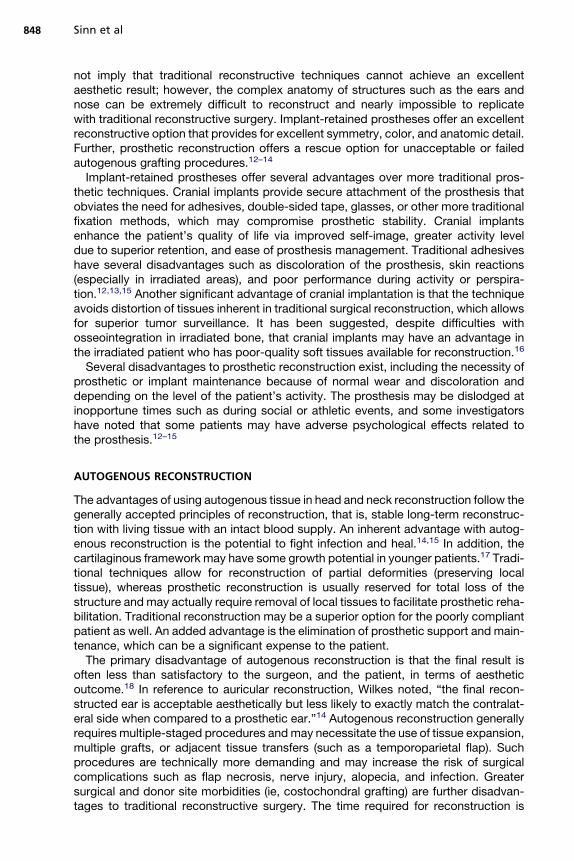
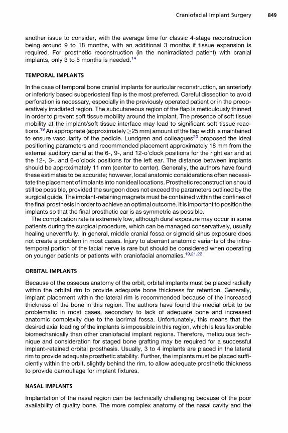
Placement of 2 to 3 implants is generally adequate for support of the substructure andthe orbital prosthesis. The preferred site is the lateral supraorbital rim, if it has not beenresected. However, implants may be placed in the residual periorbital bony rim. Aspecial consideration in treatment planning of the orbital prosthesis is the availabledepth of the orbital defect. Inadequate orbital depths do not allow the tipping of thetrajectory of the implant into the center of the orbit, resulting in inadequate spacefor the fabrication of the substructure and the orbital prosthesis. Virtual planning ofthe implants is performed, and the orbital depth is established intraoperatively bydebulking the orbital contents. The implants are placed as planned at 35 N cm(Fig. 7). Immediate postoperative implant positioning must be done in conjunctionwith proposed virtual planning. Computer-guided treatment planning allows posi-tioning of the implants in appropriate bony volume in concert with the proper trajectoryfor reconstruction of the maxillofacial prosthesis (Fig. 8). After exposure of the orbitalrim, a round bur is used to identify the implant position (Fig. 9). On completion of the2 mm osteotomy, a paralleling pin is placed to evaluate the trajectory (Fig. 10). Thefinal osteotomy depth of 3 mm is followed by insertion of the implant. Most proceduresfollow a 1-stage protocol in which the temporary healing abutment is placed at thetime of the implant surgery, with adaptation of the soft tissues (Figs. 11 and 12).Once the second implant is placed, the position of the actual surgery can becompared with the virtual surgery using the treatment planning software. Triple antibi-otic ointment application and periimplant surface pressure dressings complete thesurgical treatment. Osseointegration for 3 to 4 months is followed by fabrication ofthe substructure and the prosthetic device (Figs. 13 and 14).
Nasal Defects
Placement of the implants for supporting a nasal prosthesis is unique because accessby the maxillofacial prosthodontist must be considered during treatment planning for
Fig. 7. The implants are placed with 35 N cm insertion torque.

Fig. 8. Preoperative virtual planning of a 30-year-old man for implants to support an orbitalprosthesis.
Craniofacial Implant Surgery 855
the position of the implants. The generally accessible bone volumes, which cansupport the implants, are in the premaxilla. Placing 2 implants through the nasal floorat positions corresponding with the dental positions No. 7 and No. 10 is recommended(Fig. 15). During treatment planning, especially in the fully dentate patient, consider-ation of vital structures, including the teeth and nasopalatine canals, is essential.The use of the maxillofacial planning software allows for visualization for avoiding vitalstructures (Fig. 16). Aesthetic considerations of the final prosthesis must also beconsidered. In cases in which oncological resection was not orchestrated with maxil-lofacial reconstruction, the excess soft tissue can hinder an aesthetic prostheticoutcome (Fig. 17).Following virtual treatment planning, 2 implants are placed with implant platforms
tilted outward to allow easy access by the maxillofacial prosthodontist. The 1-stagesurgical protocol is followed. However, it is prudent to place the final abutment atthe time of surgery. Placement of the final abutment and impression coping at thetime of surgery are done in conjunction with placement of a triple antibiotic pressure
Fig. 9. To initiate the osteotomy, a round bur is used.
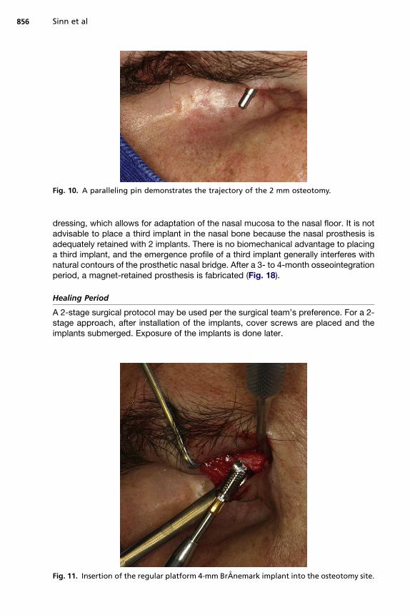
Fig. 10. A paralleling pin demonstrates the trajectory of the 2 mm osteotomy.
Sinn et al856
dressing, which allows for adaptation of the nasal mucosa to the nasal floor. It is notadvisable to place a third implant in the nasal bone because the nasal prosthesis isadequately retained with 2 implants. There is no biomechanical advantage to placinga third implant, and the emergence profile of a third implant generally interferes withnatural contours of the prosthetic nasal bridge. After a 3- to 4-month osseointegrationperiod, a magnet-retained prosthesis is fabricated (Fig. 18).
Healing Period
A 2-stage surgical protocol may be used per the surgical team’s preference. For a 2-stage approach, after installation of the implants, cover screws are placed and theimplants submerged. Exposure of the implants is done later.
Fig. 11. Insertion of the regular platform 4-mm BrAnemark implant into the osteotomy site.

Fig. 12. Placement of a healing abutment completes the 1-stage protocol.
Fig. 13. Metal framework with a magnet used as the retentive component for theprosthesis.
Fig. 14. Final magnet-retained orbital prosthesis.
Craniofacial Implant Surgery 857
Fig. 15. Implants to retain a nasal prosthesis is placed through the nasal floor (arrows) inproximity to teeth Nos. 7 and 10.
Fig. 16. The nasal floor, the hard palate, and the position of the existing teeth are readilyvisualized during the virtual planning. A safe distance is maintained between the vital teethand the implant.
Fig. 17. (A, B) Inadequate resection and site preparation result in an unaesthetic transitionline between the prosthesis and the patient’s skin.
Sinn et al858

Fig. 18. (A–C) Abutment level impression is taken after osseointegration of the implants fol-lowed by fabrication of the superstructure and the final magnet-retained nasal prosthesis.
Craniofacial Implant Surgery 859
SOFT TISSUE REACTIONS AND INFECTIONS
The rate of soft tissue reactions around percutaneous implants has been reported tobe between 3% and 60%, with significant variation reported depending on the stateddefinitions used to define a reaction.23,24 Most investigators have noted soft tissuereactions in around 3% to 7% of percutaneous implants, with most of the reactionsbeing mild erythema or irritation.16,25 In a total of 2624 postoperative implant observa-tions in 309 cranial implants (follow-up from 1–12 years), Westin and colleagues19
reported a 3% incidence of significant skin reactions. Abu-Serriah and colleagues26

Sinn et al860
found soft tissue infection to be the most common complication in a group of 150cranial implants. They also observed a decreased infection incidence after the first2 years of service in the temporal region. However, implants in the orbital and nasalregions exhibited a constant rate of soft tissue complications over time.
RADIATION AND CRANIAL IMPLANTATION
When using cranial implants for reconstruction of oncological defects of the facialskeleton, placement of implants into irradiated bone is inevitable. As with all irradiatedtissues, soft tissue fibrosis coupled with the loss of the microvasculature occurs in therecipient bed. The resulting decreased oxygen tension has a negative effect on theability to place titanium implants and obtain successful integration. Most investigatorsreport significantly increased failure rates (ranging from 17%–42%) for cranial implantsplaced into irradiated bone.16,21,27–30 When examining 81 cranial implants, Jacobssonand colleagues25 described a success rate of 62.7% (vs 92.1% in nonirradiated bone).Implants that were lost in irradiated bone when placed after a 12-month period weregenerally successful. The orbit is an especially difficult location to achieve implant inte-gration after radiation therapy.31,32 In a group of 24 orbital implants, Roumanas andcolleagues22 observed a high rate of loss in the irradiated orbit and reporteda 100% complication rate, with complications including failure to osseointegrate,late failure, tissue inflammation, and soft tissue recession. Successful implantationof the orbit is significantly more difficult to accomplish in the irradiated patient, withmost studies reporting success rates in the range of 50% to 66%.22,25,27 Despitethe adverse effect of radiation regarding cranial implant osseointegration, the risk ofcraniofacial osteoradionecrosis is low and seldom observed.16,22,27,31 The timing ofimplant placement at the conclusion of radiation therapy remains controversial withmost researchers recommending a delay of 6 to 19 months before implantplacement.22,26,27
The use of hyperbaric oxygen (HBO) has been advocated by multiple studies in theliterature to improve integration rates and optimize soft tissue healing when placingcranial implants into irradiated bone.16,26,27 When examining 125 irradiated cranialimplants, Granstrom and colleagues27 noted that 38.4% of irradiated implants werelost in the irradiated group versus 17% in the nonirradiated group. Of the irradiatedimplants, 45 received preoperative HBO therapy, and no implants were lost in thisgroup. It was concluded that HBO was extremely beneficial in the irradiated fieldbefore the placement of cranial implants. In reference to the proposed soft tissuebenefits of HBO, no statistical difference in local skin reactions was observed betweenpatients who received HBO therapy and those who did not.
PROSTHETIC CONSIDERATIONS
A stable and consistent prosthetic attachment is crucial to the successful rehabilita-tion of the patient who underwent maxillofacial surgery. For the anaplastologist orpractitioner who is designing and fabricating prostheses, implementing cranialimplants can significantly help meet the needs of the patient. Anaplastology iscommonly defined as the application of prosthetic materials for reconstruction of anabsent, disfigured, or missing body part (from the Greek anameaning again, and plas-tos meaning something made or formed). “The anaplastologist is charged with theformidable task of restoring the delicate beauty of the human ear.”33 This task isassigned and applied to all facial prosthetic reconstructions.
Craniofacial Implant Surgery 861
PREOPERATIVE PLANNING
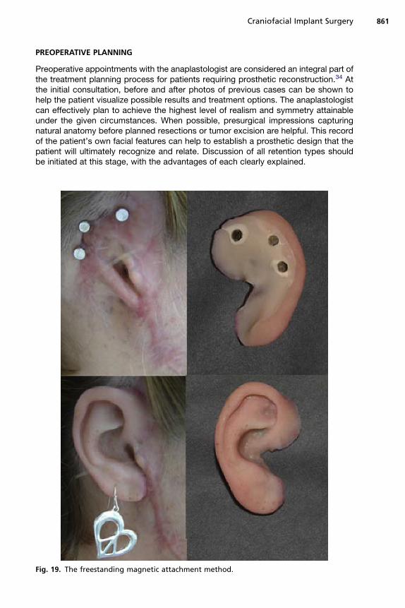
Preoperative appointments with the anaplastologist are considered an integral part ofthe treatment planning process for patients requiring prosthetic reconstruction.34 Atthe initial consultation, before and after photos of previous cases can be shown tohelp the patient visualize possible results and treatment options. The anaplastologistcan effectively plan to achieve the highest level of realism and symmetry attainableunder the given circumstances. When possible, presurgical impressions capturingnatural anatomy before planned resections or tumor excision are helpful. This recordof the patient’s own facial features can help to establish a prosthetic design that thepatient will ultimately recognize and relate. Discussion of all retention types shouldbe initiated at this stage, with the advantages of each clearly explained.
Fig. 19. The freestanding magnetic attachment method.

Sinn et al862
Options with Cranial Implant Surgery
An implant-retained prosthesis provides a secure and consistent method of attach-ment. Themechanical connection between the patient and the prosthesis can alleviatepsychological concerns that the prosthesis will become loose or dislodge at anytime.35 It also ensures exact positioning without the need of a mirror or care giver.In addition, the life span of an implant-retained prosthesis is typically longer thanthat requiring adhesive because of the less wear and tear associated with the adhesiveremoval process.When the surgically placed implant-retained type is chosen, the bar and clip versus
magnetic attachment option should be decided presurgically (Figs. 19 and 20). Thisdecision will determine how many exposed implants are needed. Experience hasshown that the gold bar arrangement proves more difficult for many patients to clean
Fig. 20. The gold bar and clip attachment method.

Fig. 21. Patient cast, prototyped model, and the final prosthesis, respectively.
Craniofacial Implant Surgery 863
than the freestanding abutments for magnetic attachment. The magnetic attachmentrequires little manual dexterity. The recently developed Maxi O-ring Magnet by Mag-naCap System, Technovent Ltd, Newport, South Wales, UK, “provides far superiorretention to that of conventional magnets.”36 In the authors’ experience, using only1 of these O-ring magnets in a prosthesis meets or surpasses the retention of a barand clip design.
Auricular Considerations
Advancements in 3D technology, such as scanning and milling machines, provide foraccurate reproduction of contralateral auricular forms. Using such devices helps thepractitioner accurately and quickly achieve a certain level of symmetry (Fig. 21). The
Fig. 22. Modification of cartilaginous tissue for the construction of a neotragus and pros-thetic reconstruction.

Sinn et al864
patient’s existing auricular cast is scanned, digitally mirror imaged, and milled in 3D.This shape gives the anaplastologist a reliable reference to design the final auricularprosthesis.In congenital cases, there are often several options to consider. Cartilaginous
remnants from failed autogenous reconstructions can be retained or sculpted andrepositioned for the construction of a neotragus. The presence of a tragus allowsthe anterior prosthetic margins to be elegantly concealed behind this anatomic feature(Fig. 22). Symmetric and well-positioned microtic tissue can remain underneath animplant-retained auricular prosthesis. Microtic tissue compromising the aestheticoutcome should be removed at the time of implant placement. However, this stepshould be clearly discussed with the patient before surgery, thus allowing plenty oftime for decision making. It is not uncommon for the patient to feel emotionallyattached to his/her microtic remnant.
TEMPLATES
Implants should be placed in an area of the prosthesis that is thick enough to containand naturally disguise retentive hardware. Designing a prototype prosthesis beforesurgery determines areas of thickness and other important features. The prototype
Fig. 23. (A–C) Ideal locations within the antihelix portion of the surgical template.

Craniofacial Implant Surgery 865
can then be used in the construction of the surgical template. The template shoulddesignate preferred implant locations (Fig. 23A, C) and other optional sites in casefavored locations are not acceptable due to poor bone quality. Templates shouldconform passively to the surgical site during surgery. Nearby anatomic features shouldbe built into the template design to ensure proper placement. Various materials, suchas acrylic or silicone, are used in template fabrication.
Auricular Templates
The basic reference mark in locating potential auricular implant sites is the middle ofthe external auditory canal. Using this landmark, the ideal location is found to beapproximately 20 mm from the center of the external auditory meatus. Using theselocations within the template should allow for retentive hardware to be concealed inthe antihelix portion of the prosthesis (see Fig. 23).
CONSTRUCTION OF THE PROSTHESIS
The final visual prosthetic result depends on achieving a delicate balance of manyfactors during all stages of construction. Fabrication begins with capturing an accu-rate impression. Soft tissue movement, areas of sensitivity, and hair surrounding thesite should be taken into account.An accurate impression material must be used to precisely register the abutments
and record soft tissue. Applying 2 layers of polyvinyl siloxane material provides therequired exactness. A thin light-bodied layer is applied followed by a heavy-bodiedmaterial to stabilize the impression hardware (Fig. 24). For magnetic attachments(see Fig. 24), the transfer magnet remains within the impression and is used for regis-tering the laboratory analogue abutments within the cast. The cast obtained from thiscaptured impression serves as the master cast on which the definitive prosthesis is
Fig. 24. (A) Transfer magnets in location. (B) Two-layered impression technique.

Fig. 25. Margins of an orbital prosthesis disguised behind the patient’s frames.
Sinn et al866
built. Input and feedback from the patient should be especially encouraged during thisstage. A prototype form should be tried on and examined by both the patient and theanaplastologist. The boundary of an orbital prosthesis can be effectively disguisedbehind the edges of the patient’s glasses (Fig. 25).
Color and Tinting of the Prosthesis
Creating realistic skin colors in silicone requires selecting a combination of colorantthat mimics the absorption and transmission of human skin.37 To achieve a high levelof realism, several factors must be taken into consideration: opacity/translucency, hue(color), value (too dark or too light), and chroma (intensity).33 Various lighting condi-tions can alter any of these aspects of color.The final result should be undetected at a normal conversational distance and
should prevent the patient from having his/her condition recognized in social situa-tions. This result transforms the patient’s self-esteem and overall presentation.Symmetry, organic form, and attention to color detail contribute to the patient’sacceptance of the prosthetic silicone feature.
SUMMARY
Extraoral cranial implant-retained prosthetic reconstructions have been proved to behighly successful. Replacement of the eyes, ears, nose, and larger areas includingcombined midface defects, which frequently have no other option available, hasbeen done successfully. Burn patients and those with congenital defects are goodcandidates for this type of reconstruction, especially after autogenous attempts

Craniofacial Implant Surgery 867
have failed. Cranial implant prosthetic reconstruction should be considered as a viableoption for difficult craniofacial defects.
REFERENCES
1. Branemark PI, Adell R, Breine U, et al. Intra-osseous anchorage of dental pros-thesis. I. Experimental studies. Scand J Plast Reconstr Surg 1969;3:81–100.
2. Adell R, Hansson BO, Branemark PI, et al. Intra-osseous anchorage of dentalprosthesis. II. Review of clinical approaches. Scand J Plast Reconstr Surg1970;4:19–34.
3. Branemark PI, Breine U, Hallen O, et al. Repair of defects in mandible. Scand JPlast Reconstr Surg 1970;4:100–8.
4. Branemark PI, Breine U, Adell R, et al. Experimentella studier av intraosseal for-ankring av dentala proteser. Rsbok/Goteborgs Tandlakare-Sallskaps 1970;9–25[in Swedish].
5. Branemark PI, Adell R, Hansson BO. Kakrekonstruktion och benforankrand bet-tersattning. Tandlakartidningen 1971;63:486–97 [in Swedish].
6. Tjellstrom A, Hakansson B, Lindstrom J, et al. Analysis of the mechanical imped-ance of bone-anchored hearing aids. Acta Otolaryngol 1980;89:85–92.
7. Tjellstrom A, Lindstrom J, Nylen O, et al. The bone-anchored auricular episthesis.Laryngoscope 1981;91:811–915.
8. Albrektsson T, Branemark PI, Hansson HA, et al. Osseointegrated titaniumimplants. Requirements for ensuring a long-lasting direct bone-to-implantanchorage in man. Acta Orthop Scand 1981;52:155–70.
9. Tjellstrom A, Lindstrom J, Hallen O, et al. Osseointegrated titanium implants in thetemporal bone. A clinical study on bone-anchored hearing aids. Am J Otol 1981;2:304–10.
10. Branemark PI, Albrektsson T. Titanium implants permanently penetrating humanskin. Scand J Plast Reconstr Surg 1982;16:17–21.
11. Tjellstrom A, Lindstrom J, Nylen O, et al. Directly bone-anchored implants for fixa-tion of aural episthesis. Biomaterials 1983;4:55–7.
12. Tjellstrom A, Rosenhall U, Lindstrom J, et al. Five year experience with skin-penetrating bone-anchored implants in the temporal bone. Acta Otolaryngol1983;95:568–75.
13. Tjellstrom A, Yontichev E, Lindstrom J, et al. Five years experience with bone-anchored auricular prosthesis. Otolaryngol Head Neck Surg 1985;93:366–72.
14. Wilkes GH, Wolfaardt J. Osseointegrated alloplastic versus autogenous earreconstruction: criteria for treatment selection. Plast Reconstr Surg 1994;93:967–79.
15. Wolfaardt JF, Tam V, Faulkner M, et al. Mechanical behavior of three maxillofacialprosthetic adhesive systems: a pilot project. J Prosthet Dent 1992;68:943.
16. Granstrom G, Tjellstrom A, Branemark P, et al. Bone-anchored reconstruction ofthe irradiated head and neck cancer patient. Otolaryngol Head Neck Surg 1993;108:334–43.
17. Thomson HG, Winslow J. Microtia reconstruction: does the cartilage frameworkgrow? Plast Reconstr Surg 1989;84:908.
18. Brent B. Personal approach to total auricular construction. Clin Plast Surg 1981;8:211–21.
19. Westin T, Tjellstrom A, Hammerlid E, et al. Long-term study of quality and safety ofosseointegration for the retention of auricular prostheses. Otolaryngol Head NeckSurg 1999;121:133–43.
Sinn et al868
20. Lundgren S, Moy PK, Beurmer J, et al. Surgical considerations for endosseousimplants in the craniofacial region: a 3-year report. Int J Oral Maxillofac Surg1993;22:272–7.
21. Wolfaardt J, Wilkes G, Parel S, et al. Craniofacial osseointegration: the Canadianexperience. Int J Oral Maxillofac Implants 1993;8:197–204.
22. Roumanas E, Nishimura R, Beumer J, et al. Craniofacial defect and osseointe-grated implants: six-year follow-up report on the success rates of craniofacialimplants at UCLA. Int J Oral Maxillofac Implants 1994;9:579–85.
23. Abu-Serriah MM, McGowan DA, Moos KF, et al. Outcome of extraoral craniofacialendosseous implants. Br J Oral Maxillofac Surg 2001;39:269–75.
24. Holgers KM, Tjellstrom A. Soft tissue reaction around percutaneous implants:a clinical study on skin-penetrating titanium implants used for bone-anchoredauricular prostheses. Int J Oral Maxillofac Implants 1987;2:35–8.
25. Jacobsson M, Tjellstrom A, Fine L, et al. A retrospective study of osseointegratedskin-penetrating titanium fixtures used for retaining facial prostheses. Int J OralMaxillofac Implants 1992;75:523–8.
26. Abu-Serriah MM, McGowan DA, Moos KF, et al. Extraoral craniofacial endo-sseous implants and radiotherapy. Int J Oral Maxillofac Surg 2003;32:585–92.
27. Granstrom G, Bergstrom K, Tjellstrom A, et al. A detailed analysis of titaniumimplants 1994;653–62.
28. Scheon PJ, Raghoebar GM, Reinstema H, et al. Treatment outcome of bone-anchored craniofacial prostheses after tumor surgery. Cancer 2001;92(12):3045–50.
29. Granstrom G, Jacobsson M, Tjellstrom A. Titanium implants in irradiated tissue:benefits from hyperbaric oxygen. Int J Oral Maxillofac Implants 1992;7:15–25.
30. JacobssonM, TjellstromA, Thomsen P, et al. Integration of titanium implant in irradi-ated bone: histologic and clinical study. Ann Otol Rhinol Laryngol 1988;97:337–40.
31. Parel SM, Tjellstrom A. The United States and Swedish experience with osseoin-tegration and facial prosthesis. Int J Oral Maxillofac Implants 1991;6:75–9.
32. Gion GG. Surgical versus prosthetic reconstruction of microtia. The case for pros-thetic reconstruction. J Oral Maxillofac Surg 2006;64:1639–54.
33. Hemar P, Reidinger-Keller AM. Optimal surgical procedures following tumorresection for successful prosthetic rehabilitation by means of osseointegratedcraniofacial implants. Int J Anaplast 2009;3:17–24.
34. Schaaf NG, Kielich M. Implant-retained facial prostheses. In: McKinstry RE,editor. Fundamental of facial prosthetics. Arlington (VA): ABI Professional Publi-cations; 1995. p. 169–79.
35. Thomas KF. Prosthetic rehabilitation. London: Quintessence Publishing; 1994. 21.p. 169–93.
36. Vistafix� treatment guide. Engelwood (CO): Cochlear Americas; 2007. p. 17.37. Tanner P. The use of light remittance measurements to determine intrinsic
pigment concentrations in designing a realistic auricular prosthesis. Int J Ana-plast 2008;2:7–14.
FURTHER READINGS
Belus JF, Kaplanski P, Blanc JL, et al. Orbito-maxillo-facial rehabilitation with osteoin-tegrated prostheses. Ann Otolaryngol Chir Cervicofac 1996;113(7–8):397–407 [inFrench].
Cervelli V, Bottini DJ, Arpino A, et al. Orbital reconstruction: bone-anchored implants.J Craniofac Surg 2006;17(5):848–53.

Craniofacial Implant Surgery 869
Miles BA, Sinn DP, Gion GG. Experience with cranial implant-based prosthetic recon-struction. J Craniofac Surg 2006;17(5):889–97.
Roumanas ED, Chang TL, Beumer J. Use of osseointegrated implants in the restora-tion of head and neck defects. J Calif Dent Assoc 2006;34(9):711–8.
Schaaf NG. Maxillofacial prosthetics in the head and neck cancer patient. Cancer1984;54(Suppl 11):2682–90.
Tolman DE, Tjellstrom A, Woods JE. Reconstructing the human face by using thetissue-integrated prosthesis. Mayo Clin Proc 1998;73(12):1171–5.
Van Doorne JM. Extra-oral prosthetics; past and present. J Invest Surg 1994;7(4):267–74.


