2011 - Shihlin Electric · non-earthing Neutral point non-earthing Normal working conditions...
12
2011.09
Transcript of 2011 - Shihlin Electric · non-earthing Neutral point non-earthing Normal working conditions...

2011.09
2011.09_e


01
SURG
E PROTEC
TIVE D
EVIC
E
Low Voltage System Surge Protective Device
BHP SeriesSucceeding the world-famous tradition of the Circuit Breaker, the Surge Protective Device (SPD), available in six rating classes (180, 100, 65, 40, 30, 15kA), launched by Shihlin Electric can be used in a variety of thunder-striking hazardous areas. It is mainly used for surge protection of electrical power.
With professional specialty in design and manufacturing, the drawable Surge Protective Device developed by Shihlin Electric not only complies with the international professional standard but also features superior quality, sophisticated design, excellent function, safety and high reliability. It is easy for installation and maintenance without disconnecting the power.
Protect Features
1 Application: Protect electric system and unloading electrical apparatus from thunder and instantaneous over-voltage2 Compliance with IEC standard, and CE Certi�cation3 Class II protection for testing 8/20µs waveform, which also can be converted to 10/350µs for Class I protection4 Faster response less than 25ns5 Standard module-type design. DIN-Rail 35mm mounting6 Equip with the visual failure indicator7 Automatic trigger for SPD replacement8 Each unit is provided with an auxiliary alarm contact set9 Counter can be added10 Operating temperature: -40℃~ +80℃11 It is applicable for AC and DC power system12 Dust/ water resistant class: IP20
Terminology
1 Maximum continuous operational voltage – Uc (V): When applying maximum e�ective value or DC voltage to the SPD, its normal function will not be degraded or restricted.
2 Protection level – Up (kV): Maximum allowable residual voltage after diverting the surge current – The smaller the value, the better the surge protection e�ect.
3 Nominal discharge current – In (kA): When applying 8/20µs waveform, the surge impact to the peak current �owing through the SPD is over 10 times.
4 Maximum discharge current Imax (kA) – 8/20µs: The higher the value, the better the surge protection e�ect. The surge impact is over 1 time.
5 Reaction time (tA): Demonstrates the action sensitivity and the breaking time of the components in the protective device.

02
SURG
E PROTEC
TIVE D
EVIC
E
BHP
Catalogue
Type
CommonDi�erential
CommonDi�erential
Grounding system
Maximumdischarge current
(Imax)
Number of poles(P)
R: with alarm auxiliary contact Blank: without alarm auxiliary contact
The standard operation voltage Uc (V) is below table. PS: Maximum Operation Voltage Uc (V): 660V
Maximumdischarge current
Standard operation voltage
To enable the surge protective device to work, please understand the following speci�cation:1. The grounding system type of the protected device and the maximum operating voltage of the power grid Us.max2. The impulse withstand voltage of the protected device.
•Common mode protection:Earth wire protection by each wire (earth wire protection by phase wire and neutral wire).
•Di�erential mode protection:Protection of earth wire and neutral wire by each wire (neutral wire protection by phase wire and earth wire protection by neutral wire).
SPD Before RCD After RCD Neutral point non-earthing
Neutral point non-earthing
Normal working conditions‧Frequency: the AC power frequency shall be 48~50Hz.‧Voltage: the voltage continuously supplied between the wiring terminals of the surge protective device shall not exceed
its maximum continuous operating voltage Uc.‧Elevation: less than 2,000m.‧Use and storage temperature: - Normal range: -5℃~ +40℃; - Ultimate range: -40℃~ +80℃;‧Humidity–relative humidity: 30%~ 90% under ambient temperature.
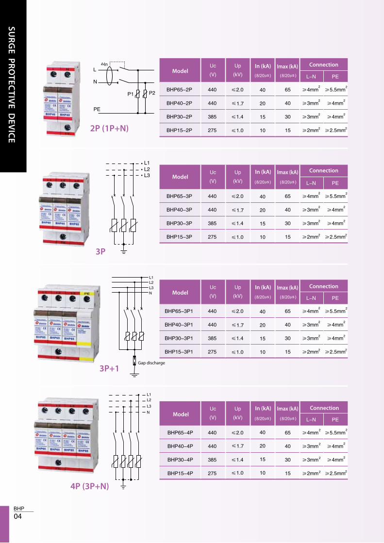
1P
1P+1
2P (1P+N)
3P
3P+1
4P (3P+N)
CommonDi�erential
CommonDi�erential
CommonDi�erential

03
SURG
E PROTEC
TIVE D
EVIC
E
Combination selection of surge protective device and circuit breakerThe internal core of SPD is one zinc-oxide pressure-sensitive element and zinc oxide consists of grains. When the surge current with energy through the SPD far exceeds its speci�ed value, ceramic breakdown will happen, and certain grain boundary layers in the ceramic will be damaged. Under extreme circumstances, excessive heat generated by over high continuous load will damage the grains, and even break the grains down under serious conditions, leading to the fusion of ZnO grains and thus causing short circuit. Since there is no time for the burst heat to transfer to the thermal cuto� mechanism, fuse or circuit breaker must be used for cutting o� the power.Even under the condition of precise parameter selection, the over high temperature rise and burst of the SPD due to overload are not eliminated.
MCBSPD
Max. discharge current Imax Rated current Trip characteristic Model
Special notes: 1. The X in the breaker model indicates the pole number, for example, to design a breaker for BHP40, in combination with 4-pole 25A breaker,the model shall be BHA24 C25.
2. The breaking capacity of the breaker must be larger than the maximum short circuit current at this position.3. Protection shall be provided for each pole of the surge protective device.4. For PT secondary line protection, due to the restriction of the maximum load current of PT, full consideration shall be given to the following
circumstances:(1) The maximum short circuit current of PT, it is noted that, when discharge with excessive energy gets SPD breakdown and short-circuit,
the secondary line shall not have high voltage paralysis. At this moment, the release current and quick response capacity of the breaker must be considered.
(2) Fuse may be considered, since standard fuse cannot be broken down by the pulse current, by contrast, the breaker can protect from the damages caused by the continuous surge with follow current or energy.
Plug-In type speci�cation
ModelConnection
ConnectionModel
40
20
15
10
40
20
15
10
1.7
1.0
1.0
1.7
Imax (kA)In (kA)
Imax (kA)In (kA)
1P
1P+1
04
SURG
E PROTEC
TIVE D
EVIC
E
Model
Model
Model
Model
Connection
Connection
Connection
Connection
Gap discharge
40
20
15
101.0
1.7
40
20
15
101.0
1.7
40
20
15
101.0
1.7
40
20
15
101.0
1.7
Imax (kA)In (kA)
Imax (kA)In (kA)
Imax (kA)In (kA)
Imax (kA)In (kA)
2P (1P+N)
3P
3P+1
4P (3P+N)

05
SURG
E PROTEC
TIVE D
EVIC
E
Installation method of SPD1. The cable for connecting SPD shall be as short as possible, since
the impedance of the wire can weaken the protection function of SPD.
2. To realize e�ective protection, it is suggested to install one lead-in device to locally divide the current at the inlet of the device.
3. When one switch device and one SPD are mounted in a serial manner, the wire shall be as short as possible.
Overlong grounding cable Short grounding cable
The plug-in module of BHP series plug-in surge protective device, there is unique pilot hole at the bottom of the base, cores of different specifications cannot be plugged in if interchanging positions. The core side is high-grade insulation material, therefore, when pulling out the core, it will not contact with charged body.
ModelConnection
Fixed type speci�cation
Dimension
Imax (kA)In (kA)

06
SURG
E PROTEC
TIVE D
EVIC
E
SPD wiring example
TN-C system three phase
TN-C-S system three phase
IT system three phase Single-Phase Power Supply Scheme
Special notes:
TN-S system three phase
Time-delay leakage protector shall be selected for the RCD in the power supply system; leakage protector insensitive to atmospheric over-voltage shall be selected for the RCD installed in residences and o�ce buildings.
Protection equipm
ent
Protection equipm
ent
SPD
SPD
SPD
SPD
Grounding connection Grounding connection
SPD
SPD
First side protection Second side protection
Protection equipm
ent
Protection equipm
ent

07
SURG
E PROTEC
TIVE D
EVIC
E
TT System Scheme 1
TT System Scheme 1 TT System Scheme 2
TT System Scheme 2
Special notes:Time-delay leakage protector shall be selected for the RCD in the power supply system; leakage protector insensitive to atmospheric over-voltage shall be selected for the RCD installed in residences and o�ce buildings.
Protection equipm
ent
Protection equipm
ent
SPD
SPDSPD
SPD SPD
Grounding connection
Main panel
Main panel Main panel
Counter
Counter sensorCounter Sensor
Gas discharge device
Secondary protection Secondary protection
Main panel Main panel
SPD
Secondary protection
Type
Pulse
Pulse falling edge, �ash accumulation record
Dimension
Digital memory method
Minimum interval between counter pulses
Count display method
Counting method
Maximum count
Counter pulse threshold
Rated working voltage
2 digits LED red
Lightning strike pulse counter can count the discharge pulses and storethem to the single-chip FLASH, and features intuitive display and small volume.
1kA
200ms
TN-C TN-S IT
Grounding connection
Gas dischange device
4P 3P+1

08
SURG
E PROTEC
TIVE D
EVIC
E


2011.09
2011.09_e