Team Atomica Conceptual Designs for cycling apparel and swimwear
date post
21-Dec-2015Category
view
215download
1
2011
CoDR
Team NameConceptual Design Review
University/InstitutionTeam Members
Date
1

2011
CoDR
User Notes
• You can reformat this to fit your design, but be sure to cover at least the information requested on the following slides
• This template contains all of the information you are required to convey at the CoDR level. If you have questions, please on’t hesitate to contact me directly:
[email protected] 720-234-4902
2
AcknowledgementThanks to Emily Logan for developing the general layout and content of these slides

2011
CoDR
Purpose of CoDR
• Confirm that:– Science objectives are
understood and well-defined– Preliminary mission
requirements are defined and traceable to science objectives
– Understand concept of operations
– Technology dependencies and alternative strategies for achieving science objectives
3
gnurf.net
2011
CoDR
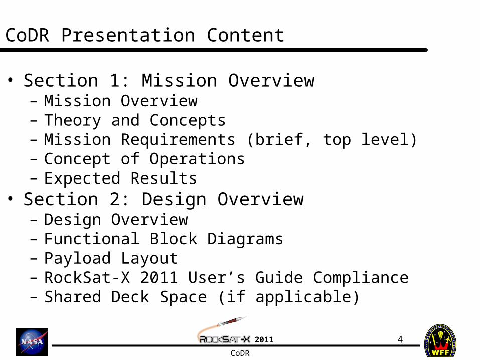
CoDR Presentation Content
4
• Section 1: Mission Overview– Mission Overview– Theory and Concepts– Mission Requirements (brief, top level)– Concept of Operations– Expected Results
• Section 2: Design Overview– Design Overview– Functional Block Diagrams– Payload Layout– RockSat-X 2011 User’s Guide Compliance– Shared Deck Space (if applicable)

2011
CoDR
CoDR Presentation Contents
• Section 3: Management– Team Organization– Schedule– Budget– Mentors (Faculty, industry)
• Section 4: Conclusions
5
jessicaswanson.com
2011
CoDR
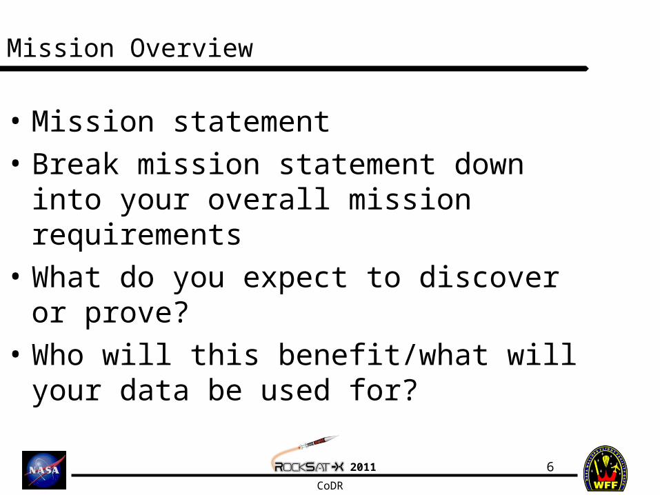
Mission Overview
• Mission statement• Break mission statement down into
your overall mission requirements• What do you expect to discover or
prove?• Who will this benefit/what will your
data be used for?
6
2011
CoDR
Mission Overview: Theory and Concepts
• Give a brief overview of the underlying science concepts and theory
• What other research has been performed in the past?– Results?
7

2011
CoDR
Mission Overview: Mission Requirements
• Project requirements derived from mission statement– Break down into mission objectives, system
level objectives (example on following slide)• Minimum success criteria
– What is the least amount of data you can collect that will still constitute a success?
8
crestock.com

2011
CoDR
Mission Overview: Mission Requirements
• The payload shall conform to the requirements set forth in the 2011 RockSat-X User Guide
• The system shall measure the numerical density of charged particles in the upper atmosphere from 30±5 km to 50±5 km
• The system should measure the numerical density of charged particles in the upper atmosphere from 30±1 km to 50±1 km
Shall is legally binding and indicative of minimum success
Should are an ideal metrics of performance that would lead to better science/performance, but are not required for minimum success.
9
crestock.com

2011
CoDR
Mission Overview: Concept of Operations
• Based on science objectives, diagram of what the payload will be doing during flight, highlights areas of interest
• Example on following 2 slides
10

2011
CoDR
Example ConOps
t ≈ 1.3 min
Altitude: 75 km
Event A Occurs
t ≈ 15 min
Splash Down
t ≈ 1.7 min
Altitude: 95 km
Event B Occurs
-G switch triggered
-All systems on
-Begin data collection
t = 0 min
t ≈ 4.0 min
Altitude: 95 km
Event C OccursApogee
t ≈ 2.8 min
Altitude: ≈115 km
End of Orion Burn
t ≈ 0.6 min
Altitude: 52 km
t ≈ 4.5 min
Altitude: 75 km
Event D Occurs
Altitude
t ≈ 5.5 min
Chute Deploys

2011
CoDR
1
2
3
4
5
6
1. Launch 1. Launch Telemetry/GPS beginsTelemetry/GPS begins
2. Launch to Apogee2. Launch to Apogee Telemetry/GPS continuesTelemetry/GPS continues
3. Apogee3. Apogee Nose cone separationNose cone separation Skin separationSkin separation De-spin to TBD rateDe-spin to TBD rate Option to align with B FieldOption to align with B Field Telemetry/GPS continuesTelemetry/GPS continues
4. Descent4. Descent Telemetry/GPS continuesTelemetry/GPS continues
5. Chute Deploy5. Chute Deploy Telemetry/GPS continuesTelemetry/GPS continues
6. Landing6. Landing Telemetry/GPS terminatesTelemetry/GPS terminates Payloads recoveredPayloads recovered
ACS Activated (if desired)ACS Activated (if desired)
Example ConOps
12
2011
CoDR
Mission Overview: Expected Results
13
• This is vital in showing you understand the science concepts
• Go over what you expect to find– Ex. What wavelengths do you expect to
see? How many particles do you expect to measure? How well do you expect the spin stabilizer to work (settling time?)? How many counts of radiation? etc
2011
CoDR
Design Overview
14
• Utilization of heritage elements (designs/features used on previous flights) defined. How will you be modifying them for your specific mission?– Will you be using stacked
configuration, makrolon, same type of sensor as a previous flight?
• Major technology dependencies: what kind of sensors will you need?– What do the capabilities of the sensors
need to be? (ex. For an optical sensor, what wavelengths should it be able to detect? This is based on project requirements)
clipartguide.com

2011
CoDR
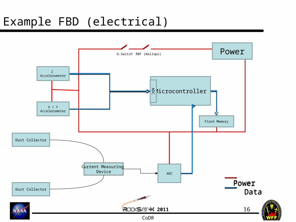
Design Overview: Functional Block Diagrams
• Functional block diagram– Shows how systems interact
with each other– Mechanical – will show how
payload is configured, especially if there are sensors external to the payload
– Electrical – shows how data will be recorded, stored
• Example on following slide
15
blogs.msdn.com
2011
CoDR
Example FBD (electrical)
16
Microcontroller
PowerG-Switch RBF (Wallops)
AD
CDust Collector
Dust Collector
ADC
Flash Memory
Z Accelerometer
X / Y Accelerometer
Current Measuring Device
Power Data
Power Data

2011
CoDR
Example FBD – mechanical/system (rough diagram)
17
Makrolon plate
Electronics - storing data
(mounted to plate)
Power
RockSat-X Deck
Sensor(s)
Electronics – controlling sensor (mounted to plate)
Hardware mounted to RockSat-X Deck
Mounts to RockSat-X Payload Deck

2011
CoDR
Design Overview: Payload Layout
• Initial drawings / layout in canister• Preliminary idea of how many plates you will use (if you
plan on using plate configuration), else idea of where and how things will be mounted
• Show where electronics boards (~how many?), sensors, power will be mounted– A little more organized than system block diagram (actually
shows standoffs, spacing between elements)
18
classymommy.com
This is NOT required at the CoDR level. If you can include this, you are ahead of the game!

2011
CoDR
Design Overview: RockSat-X 2011 User’s Guide Compliance
19
• Rough Order of Magnitude (ROM) mass estimate
• Estimate on payload dimensions (will it fit in the payload space?)
• Deployables/booms?• How many ADC lines?
– Do you understand the format?• Asynchronous use?
– Do you understand the format?• Parallel use?
– Do you understand the format?• Power lines and timer use?
– What do you know so far?• CG requirement
– Do you understand the requirement• Are you utilizing high voltage?

2011
CoDR
Design Overview: Shared Can Logistics
20
• Who are you sharing with?– Summary of your partner’s
mission (1 line)• Plan for collaboration
– How do you communicate?– How will you share designs
(solidworks, any actual fit checks before next June)?
• Structural interface – will you be joining with standoffs or something else (again, be wary of clearance)?
grandpmr.com

2011
CoDR
Management
21
• Team organization chart• Preliminary schedule for the
semester• Monetary budget• Team mentors (industry, faculty)?
Don’t let the schedule sneak up on you!

2011
CoDR
• Restate mission• Issues, concerns, any questions• Plan for where you will take your design
from here?– Anything you need to investigate further?– Are you ready make subsystem and lower level
requirements to come up with a rough-draft design for PDR?
Conclusion
22