©2011 Caterpillar® All rights reserved. - Borusan Cat and Generator Set Ratings For offshore...
83
©2011 Caterpillar® All rights reserved.
Transcript of ©2011 Caterpillar® All rights reserved. - Borusan Cat and Generator Set Ratings For offshore...

©2011 Caterpillar® All rights reserved.


©2011 Caterpillar® All rights reserved.
Introduction ......................................................................... 1
Engine Selection ........................................................................................ 1
Engine and Generator Set Ratings................................................................ 1
Basic C175 Diesel Engine Design .......................................... 1
Example Diesel Generator Package Scope of Supply ............. 2
Air Inlet System ........................................................................................ 2
Communications ....................................................................................... 2
Cooling System ......................................................................................... 2
Engine Control System ............................................................................... 2
Exhaust System ........................................................................................ 2
Fuel System .............................................................................................. 2
Instrumentation ......................................................................................... 3
Protection System ..................................................................................... 3
Starting System ........................................................................................ 4
General .................................................................................................... 4
Generators ........................................................................... 5
Cat® Kato Drilling Generator ....................................................................... 5
Technical Data ...................................................................... 8
C175-16 Technical Data Sheet ................................................................... 8
Lubrication Oil System ........................................................ 11
General .................................................................................................. 11
Internal Lubrication System ...................................................................... 11
Prelubrication .......................................................................................... 11
Postlubrication ........................................................................................ 11
Oil Requirements ..................................................................................... 12
Oil Change Interval .................................................................................. 12

©2011 Caterpillar® All rights reserved.
Inclination Capability ................................................................................ 13
Customer Piping Connections ................................................................... 13
Crankcase Ventilation System ............................................. 14
Crankcase Emissions ............................................................................... 14
Crankcase Fumes Disposal ....................................................................... 14
Customer Piping Connections ................................................................... 14
Fuel System ....................................................................... 15
General .................................................................................................. 15
External Fuel System Design Considerations ............................................... 16
Miscellaneous Fuel System Considerations ................................................. 17
Fuel Recommendations ............................................................................ 17
Customer Piping Connections ................................................................... 17
Cooling System .................................................................. 18
General .................................................................................................. 18
Internal Cooling System ........................................................................... 18
External Cooling System .......................................................................... 18
External Cooling System Design Considerations .......................................... 19
Cooling Water Requirements ..................................................................... 21
Customer Piping Connections ................................................................... 21
Starting Air System ............................................................ 22
General .................................................................................................. 22
Internal Starting Air System ...................................................................... 22
External Starting Air System Design Considerations ..................................... 22
Engine Piping Connections ........................................................................ 22
Combustion Air System ...................................................... 23
General .................................................................................................. 23
Combustion Air System Design Considerations ........................................... 23

©2011 Caterpillar® All rights reserved.
Engine Room Ventilation ..................................................... 25
General .................................................................................................. 25
Sizing Considerations ............................................................................... 25
Engine Room Temperature ........................................................................ 26
Ventilation Fans ...................................................................................... 28
Exhaust Fans .......................................................................................... 29
Routing Considerations ............................................................................ 29
Exhaust System .................................................................. 34
General .................................................................................................. 34
Exhaust System Design Considerations ...................................................... 34
Engine Governing and Control System ................................ 36
Introduction ............................................................................................ 36
Generator Engine Governing System .......................................................... 36
Engine Monitoring and Shutdown ....................................... 36
Engine Shutdown .................................................................................... 36
Alarms ................................................................................................... 36
Engine Derate ......................................................................................... 36
Sensors .................................................................................................. 36
MDP 3.0 (Standard Panel) ........................................................................ 37
GMS 3.0 (Optional Panel) ......................................................................... 39
Packaged Genset Foundation and Mounting ........................ 43
Foundation Design ................................................................................... 43
Mounting ................................................................................................ 43
General Arrangement Drawings .......................................... 44
C175-16 Diesel Generator Package General Arrangement Drawings .............. 44
Petroleum C175-16 P&ID Drawings ........................................................... 50

©2011 Caterpillar® All rights reserved.
Miscellaneous .................................................................... 55
C175 Witness Test Description ................................................................. 55
Maintenance Interval Schedule .................................................................. 57
Reference Material ............................................................. 59
Project Checklist ................................................................ 60
Environmental / Site Conditions ................................................................. 60
Air Intake System .................................................................................... 61
Engine Cooling System ............................................................................ 62
Generator Cooling ................................................................................... 63
Starting System ...................................................................................... 64
Exhaust System ...................................................................................... 65
Fuel System ............................................................................................ 66
Engine Lubrication System ........................................................................ 67
Generator Lubrication ............................................................................... 68
Mounting ................................................................................................ 69
Control / Monitoring System ..................................................................... 70
Engine Room Ventilation System ............................................................... 71
Crankcase Ventilation .............................................................................. 72
Generator Requirements ........................................................................... 73
Special Testing ....................................................................................... 74
Documentation ....................................................................................... 74
Spare Parts / Special Tools ....................................................................... 75
Lifting .................................................................................................... 75
Training .................................................................................................. 76
Signatures .............................................................................................. 76
Cat®, Caterpillar, their respective logos, “Caterpillar Yellow” and the Power edge trade dress, as well as corporate and product identity used herein, are trademarks of Caterpillar and may not be used without permission.

©2011 Caterpillar® All rights reserved. 1
GE
NE
RA
L
Introduction
Engine Selection The use of Caterpillar engines in Petroleum Offshore Electric Power Generation
applications requires specific considerations for engine selection and installation to ensure dependable performance and a long, trouble-free life.
Engine and Generator Set Ratings For offshore drilling rigs, Caterpillar provides C175 engine ratings designed for
40% Load Factor and 6,000 operating hours per year. Caterpillar supplied generators are rated for Continuous operation. This type of package allows the generator set to be operated above the 40% load factor for extended periods of time due to weather related situations with only a minor reduction in Time Before Overhaul hours. Overload power of 110% of the continuous power at a speed corresponding to the engine application is permitted for a period of 1 hour, with or without interruption, within 12 hours of operation. The engine/generator set shall not experience any alarm conditions while running at 110% load for on continuous hour. Additionally, the engine/generator set shall have the ability to run 100% load without interruption.
For other applications, site load requirements and number of operating hours should be reviewed with a Caterpillar dealer to determine the best product and rating fit for the application.
Basic C175 Diesel Engine Design The C175 Drilling Module for offshore platform applications is a modern, highly
efficient, EPA Marine Tier 2, IMO II certified engine series. These are four stroke, non-reversible engines rated at speeds of 1200 rpm intended for use as electric power generator drivers for offshore platforms.

C175 PETROLEUM OFFSHORE PROJECT GUIDE
©2011 Caterpillar® All rights reserved. 2
GE
NE
RA
L
Example Diesel Generator Package Scope of Supply The following is a typical scope of supply for a C175-16 offshore drilling module.
This is an example only; the scope of supply varies with the application to meet specific customer needs, based on additional options discussed in the system sections.
Air Inlet System • Corrosion resistant separate circuit aftercooler core
• Regular duty air cleaners with service indicator
• Dual turbochargers
Communications • J1939 data link
Cooling System • Auxiliary low temperature coolant pump
• Gear driven centrifugal high and low temperature coolant pumps
• Engine oil cooler
• Electronic thermostats in both high and low temperature circuits
Engine Control System • Cat® ADEM™ A4 engine control unit (ECU)
• Cat® common rail fuel system
• Rigid wiring harness
Exhaust System • Dry gas-tight exhaust manifolds with thermo-laminated heat shields
• Dual turbochargers with water-cooled bearings and thermo-laminated heat shields
• Vertical exhaust outlet
Fuel System • Cat® common rail fuel system with electronically controlled injectors
• Series Four-micron-rated fuel filters with service indicators with duplex capability
• Electric fuel priming pump
• Gear driven fuel transfer pump

©2011 Caterpillar® All rights reserved. 3
GE
NE
RA
L
Instrumentation • Engine oil pressure
• Engine water temperature
• Fuel pressure
• System DC voltage
• Available with optional thermo couple module
• Fuel filter differential
• Engine speed
• Overspeed shutdown notification light with optional annunciator
• Oil filter differential
• Hour meter
• Lube oil system
• Top mounted dual crankcase breathers
• Oil filter with service indicators
• Oil level gauge
• Oil filler
• Gear type oil pump
• Deep sump oil pan
Protection System ADEM A4 ECU monitoring system provides engine deration, alarm, or shutdown
strategies to protect against adverse operating conditions. Selected parameters are customer programmable. Initially set as follows:
Safety shutoff protection - electrical: • Oil pressure
• Water temperature
• Overspeed
• Crankcase pressure
• Aftercooler temperature
• Air inlet shutoff activated on overspeed or emergency stop
• Oil pressure and water temperature (non-redundant, uses OP and WT sensors)
• Overspeed (redundant and independent of engine governing system)
Alarms - electrical: • ECU voltage
• Oil pressure
• Water temperature (low and high)
• Overspeed

C175 PETROLEUM OFFSHORE PROJECT GUIDE
©2011 Caterpillar® All rights reserved. 4
GE
NE
RA
L
• Crankcase pressure
• Aftercooler temperature Low water level (sensor is optional attachment)
• Air inlet restriction
• Exhaust stack temperature
• Filter differential pressure (oil and fuel)
Derate - electrical: • High water temperature
• Crankcase pressure
• Aftercooler temperature
• Air inlet restriction
• Altitude
• Exhaust temperature
• Alarm switches (oil pressure and water temperature), for connection to customer-supplied alarm panel
Starting System • Air starting motor - RH, 415 to 690 kPa (60 to 100 psi dynamic)
General • Vibration damper and guard
• Cat® yellow paint
• Close-coupled two-bearing generator

©2011 Caterpillar® All rights reserved. 5
GE
NE
RA
L
Generators Caterpillar C175 Offshore Generator Sets are packaged with close-coupled two-
bearing generators, matched to the engine output to provide the customer maximum electrical output to meet their requirements, as well as marine classification requirements for the application. Generator specifications and generator testing requirements will need to be reviewed during the pre-sale phase of the project and established prior to order placement. Options to be considered should include sub-transient reactance needed to meet transient responses required and type of current transformers to be mounted and supplied for the project. Below is an example of the data that is available in TMI.
The following Technical Data Sheet represents the latest available C175 series technical information at the time of publication and is subject to change. For the current Technical data sheet please reference LEHW6097 in Electronic Media Center or view the data in TMI base off the feature code.
Cat® Kato Drilling Generator Specifications
Poles 6 Excitation PMG Pitch 0.778
Connection Wye Maximum Overspeed (60 seconds) 125%
Number of Bearings 2 Number of Leads 6 Number of Terminals 4
Ratings
Power 1833.3 ekW
kVa 2619 Pf 0.7 Voltage – L.L… 600 V
Voltage – L.N… 346 V Current – L.L… 2520 A Frequency 60 Hz
Speed 1200 rpm
Exciter Armature Data at Full Load, 0.7 pf
Voltage 192.0 V Current 102.0 A

C175 PETROLEUM OFFSHORE PROJECT GUIDE
©2011 Caterpillar® All rights reserved. 6
GE
NE
RA
L
Temperature and Insulation Data
Ambient Temperature 50°C (122°F)
Temperature Rise 90°C (194°F) Insulation Class F Insulation Resistance (as shipped) 100 Megaohms (at 40°C)
Resistances
Base Impedance 0.137 ohms Stator (at 25°C) 0.001 ohms
Field (at 25°C) 1.30 ohms Zero Sequence R0 0.00 ohms Positive Sequence R1 0.00 ohms
Short Circuit Ratio 0.68
Fault Currents Instantaneous 3-Ø Symmetrical Fault Current 12,001 amps
Instantaneous L-N Symmetrical Fault Current 13,747 amps
Instantaneous L-L Symmetrical Fault Current 9,489 amps
Efficiency and Heat Dissipation (per NEMA and IEC at 95°C)
Load PU Kilowatts Efficiency Heat Rejection
0.25 458.3 90.9% 156,598 Btu/hr 0.5 916.7 94.3% 189,105 Btu/hr
0.75 1375.0 95.1% 241,795 Btu/hr 1.00 1833.3 94.8% 343,214 Btu/hr
Time Constants OC Transient - Direct Axis T’DO 2.955 sec. SC Transient - Direct Axis T’D 0.557 sec. OC Subtransient - Direct Axis T”DO 0.030 sec. SC Subtransient - Direct Axis T”D 0.022 sec. OC Subtransient - Quadrature Axis T”QO 0.015 sec. SC Subtransient - Quadrature Axis T”Q 0.004 sec. Armature SC TA 0.079 sec.
©2011 Caterpillar® All rights reserved. 7
GE
NE
RA
L
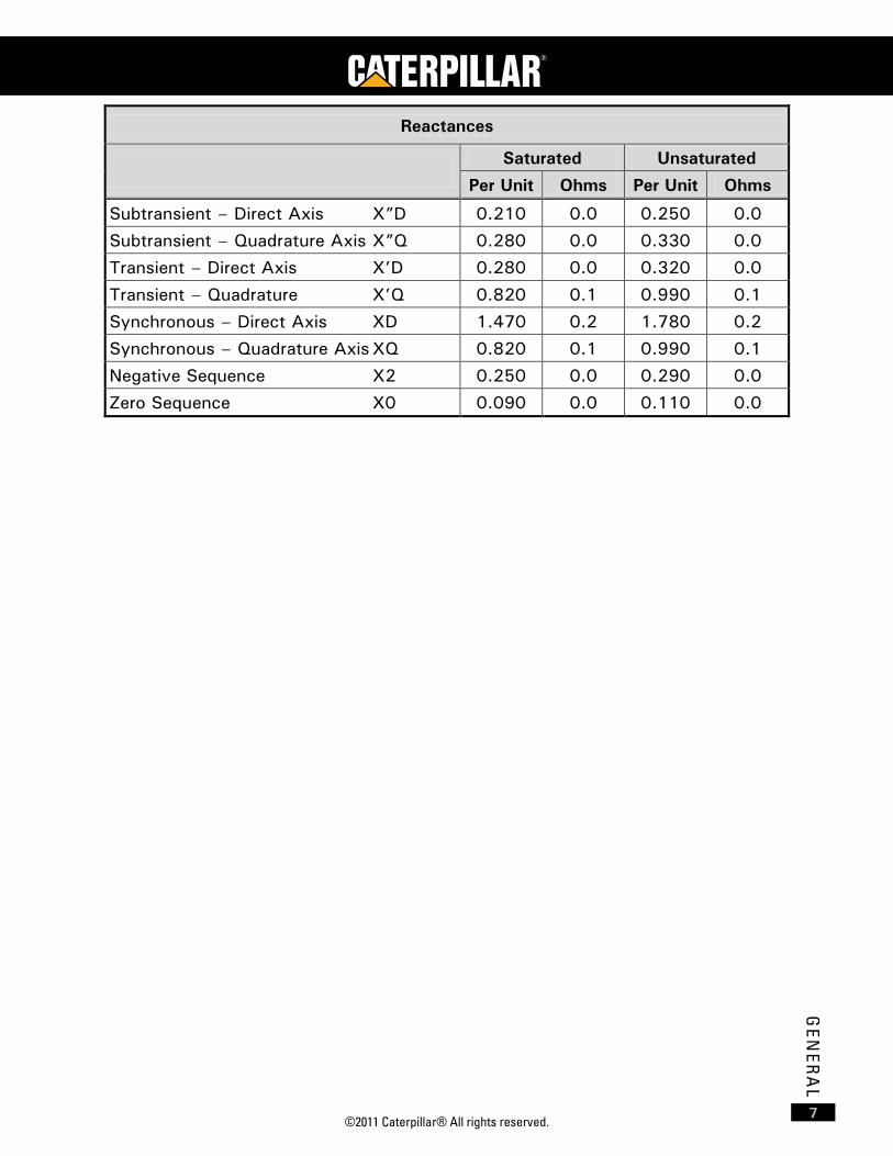
Reactances
Saturated Unsaturated
Per Unit Ohms Per Unit Ohms
Subtransient – Direct Axis X”D 0.210 0.0 0.250 0.0 Subtransient – Quadrature Axis X”Q 0.280 0.0 0.330 0.0 Transient – Direct Axis X’D 0.280 0.0 0.320 0.0
Transient – Quadrature X’Q 0.820 0.1 0.990 0.1 Synchronous – Direct Axis XD 1.470 0.2 1.780 0.2 Synchronous – Quadrature Axis XQ 0.820 0.1 0.990 0.1
Negative Sequence X2 0.250 0.0 0.290 0.0 Zero Sequence X0 0.090 0.0 0.110 0.0

C175 PETROLEUM OFFSHORE PROJECT GUIDE
©2011 Caterpillar® All rights reserved. 8
TE
CH
NIC
AL
DA
TA
Technical Data
C175-16 Technical Data Sheet The following Technical Data Sheet represents the latest available C175 series
technical information at the time of publication and is subject to change. For the current Technical data sheet please reference LEHW6097 in Electronic Media Center or view the data in TMI base off the feature code.
C175-16 System Description Metric
(English)
Engine Power 1930 kW (2586 hp)
BMEP @ Rated 2280 kPa (331 psi)
BSFC @ Rated 205 g/kW-hr
(0.337 lbs/bhp-hr)
Fuel Rate @ Rated 471.6 L/hr (125 gal/hr)
Total Fuel Rate with Bypass 529 L/hr
(140 gal/hr)
Maximum Allowable Fuel Temperature to Engine 70°C
(158°F)
Air Flow 11,949 kg/hr
(26,344 lbs/hr)
Air Flow based on 25°C (77°F) inlet temperature and 105 kPa (15.2 psi) inlet pressure
10,398 m³/hr (6119 cfm)
Maximum Allowable Air Temperature to Air Filters 45°C
(113°F)
Exhaust Flow 12,345 kg/hr
(27,216 lbs/hr)
Exhaust Flow based on 425°C (797°F) stack temperature and 105 kPa (15.2 psi) stack pressure
24,618 m³/hr (14,490 cfm)
Maximum Allowable Exhaust Backpressure 6.7 kPa
(27 in. H2O)
SCAC Heat Rejection 193 kW
(10,963 Btu/min)
SCAC Return Temperature to Engine at 30°C (86°F) Ambient
48°C (118°F)
JW Heat Rejection 1010 kW
(54,451 Btu/min)

©2011 Caterpillar® All rights reserved. 9
TE
CH
NIC
AL D
AT
A
System Description Metric (English)
Radiated Convective Heat Rejection 161 kW
(9,128 Btu/min)
SCAC Water Flow (min-max) 875-1080 L/min (231-285 gpm)
JW Flow 2000 L/min (528 gpm)
JW Outlet Flange 152 mm ANSI/DIN (6 in. ANSI/DIN)
JW Inlet Flange (pump) 152 mm ANSI/DIN (6 in. ANSI/DIN)
Aftercooler Outlet Flange 76 mm ANSI/DIN (3 in. ANSI/DIN)
Aftercooler Inlet Flange 152 mm ANSI/DIN (6 in. ANSI/DIN)
Exhaust Outlet Flange (single) 406 mm (16 in) adapter available
356 mm (14 in)
Engine Performance is corrected to inlet air standard conditions of 99 kPa (29.31 in. Hg) dry barometer and 25°C (77°F) temperature. These values correspond to the standard atmospheric pressure and temperature as shown in SAE J1995. Performance measured using a standard fuel with fuel gravity of 35 degrees API having a lower heating value of 42,780 kJ/kg (18,390 BTU/lb) when used at 29°C (84.2°F) where the density is 838.9 g/L (7.001 lb/U.S. gal). The corrected performance values shown for Cat® engines will approximate the values obtained when the observed performance data is corrected to SAE J1995, ISO 3046-2, ISO 8665, ISO 2288, ISO 9249, ISO 1585, EEC 80/1269, and DIN 70020 standard reference conditions.

C175 PETROLEUM OFFSHORE PROJECT GUIDE
©2011 Caterpillar® All rights reserved. 10
TE
CH
NIC
AL
DA
TA

©2011 Caterpillar® All rights reserved. 11
LUB
RIC
AT
ION
OIL S
YS
TE
M
Lubrication Oil System
General The lube system contains an oil cooler, oil filter, gear driven oil pump, pre-lube
pump and an oil pan that meets offshore tilt requirements. The following data represent the data available at the time of publication of this guide and is subject to change. For the current data on the lube system please reference LEBW4957 in Electronic Media Center or view the available component data in TMI.
Internal Lubrication System The lube system is designed to provide a constant supply of filtered, high
pressure oil. The system is meets the tilt requirements for non-emergency offshore operations.
Oil Coolers The engines are equipped an oil-to-water oil cooler providing 95°C (203°F) oil
temperature.
Oil Pan and Filters The oil pan is equipped with a 24 mesh wire screen and meets the tilt
requirements for non-emergency offshore operations. The simplex oil filter provides filtration and contains pressure sensors to determine the differential pressure for filter service. The normal operating oil pressure is 600 kPa (87 psi) and the differential specifies the filters to be changed at 100 kPa (14.5 psi) pressure drop across the filters.
Centrifugal Filters A centrifugal oil filter is not offered at this time.
Oil Pump The oil pump provides high pressure oil flow to the engine oil flow to the engine.
Prelubrication Prelubrication is a requirement for the Petroleum C175 engine. Air prelube is the
standard offering with electric prelube as an option.
Air Prelube System The pneumatic intermittent prelube system uses a package-mounted pump that is
engaged immediately prior to engine start-up.
Electric Prelube System The electric prelube system uses a package-mounted pump that is engaged
immediately prior to engine start-up.
Postlubrication The Petroleum C175 offshore drilling module does not have a "post-lube" feature.
During shutdown, the engine oil pump provides sufficient lubrication due to the inertia from the generator keeping the engine components rotating.

C175 PETROLEUM OFFSHORE PROJECT GUIDE
©2011 Caterpillar® All rights reserved. 12
LUB
RIC
AT
ION
OIL
SY
ST
EM
Oil Requirements Due to significant variations in the quality and performance of commercially
available lubrication oils, Caterpillar recommends the oils listed in the following table for the C175 engine. Additional information can be found in publication PEHJ0059.
CAT® DEO (Diesel Engine Oil) for C175 Diesel Engine
Caterpillar Oil SAE Viscosity Grade TBN
Ambient Temperature Minimum Maximum
DEO SAE 15W-40 11.3 -9.50°C (15°F) 50°C (122°F)
SAE 10W-30 11.3 -18°C (0°F) 40°C (104°F)
Use of Commercial Oil Caterpillar does not recommend the names of other commercial brands of lube
oils, but has established guidelines for their use. Commercially available lubrication oils may be used in Caterpillar C175 Engines, but they must have proof of performance in Caterpillar’s Field Performance Evaluation, included in Caterpillar document SEBU6251.
Oil Change Interval To achieve maximum life from the engine oil and provide optimum protection for
the internal engine components, a Scheduled Oil Sampling program (S•O•S) should be used. This program is available through the Caterpillar dealer network. If an S•O•S analysis program is not available, the oil change interval is recommended in accordance with the following table.
Oil Change Intervals for C175 Diesel Engines
Engine Model Lube Oil Capacity Oil Change Interval
C175-16 946 L (250 gal) 1000 Service Hours
Scheduled Oil Sampling TBN, viscosity and oil consumption trends must be analyzed every 250 hours.
The S•O•S analysis involves a two-part test program:
• Wear Analysis The Wear Analysis identifies engine wear elements present in the oil. These elements indicate the condition of the engine.
• Oil Condition Analysis The Oil Condition Analysis identifies the wear status of the oil. The program will determine oil change intervals based on trend analysis and condemning limits established for the engine.

©2011 Caterpillar® All rights reserved. 13
LUB
RIC
AT
ION
OIL S
YS
TE
M
Change Interval without Oil Analysis Results If S•O•S analysis results are not available, the initial oil change interval should be
used to determine oil change intervals. Even though oil sampling results may not be available on the recommended 250 hour intervals, oil samples should be analyzed at every oil change period, even if the turnaround time for the data is long.
Inclination Capability For offshore applications with tilt requirements, the Caterpillar packaged Offshore
Generator Sets utilize a deep wet sump and provides
• Static Fore/Aft: 15°
• Static Athwartship: 22.5°
• Dynamic (all directions): 22.5°.
Customer Piping Connections Engine Connections
• Oil Fill and Drain: 38 mm (1-1/2 in. 150# ANSI Flange)

C175 PETROLEUM OFFSHORE PROJECT GUIDE
©2011 Caterpillar® All rights reserved. 14
CR
AN
KC
AS
E V
EN
TIL
LAT
ION
SY
ST
EM
Crankcase Ventilation System
Crankcase Emissions Crankcase emissions result from combustion byproducts and/or exhaust fumes
escaping around the piston rings and into the crankcase, commonly called blow-by. If not controlled, this blow-by can contaminate the lube oil and pressurize the crankcase, possibly leading to an oil leak.
Venting the emissions to the atmosphere is a simple solution to release the pressure and trapped fumes. Managing the emissions, however, adds complexity to crankcase ventilation systems.
Current C175 diesel engines require crankcase fumes be vented to atmosphere. Crankcase breathers are provided on the Petroleum C175 engine to allow this gas to escape. A closed-loop, on-engine crankcase filtration system for the Petroleum C175 engine is not available at this time.
For the current data on the lube system please reference LEBW4958 in Electronic Media Center.
Crankcase Fumes Disposal Do not vent crankcase and integral oil sump fumes into the engine room. The oily
fumes will have a tendency to clog air filters.
Crankcase fumes should be discharged directly to the atmosphere through a venting system individual for each engine.
The engine has breathers located on each cylinder bank on the engine. Crankcase fumes vent pipes must be of sufficient size to prevent the buildup of excessive backpressure in the crankcase. Formulas for calculating backpressure can be found in the Crankcase Ventilation section of the current Application and Installation Guide. For blow-by on a new engine and a worn engine data please see TMI.
Loops or low points in a crankcase vent pipe must be avoided to prevent liquid locks from the condensation in the pipe and thus restricting the discharge of fumes. Where horizontal runs are required, install the pipe with a gradual rise of 41.7 mm/m, (½ in/ft), slope from the engine. The weight of the vent pipes will require separate off-engine supports as part of the installation design. Further additional flexible connections will need to be installed to accommodate the engine movement.
The pipe should vent directly into the atmosphere at a well-considered location and be fitted with a gooseneck or similar arrangement to keep rain or water spray from entering the engine. Consideration should also be given to other equipment located near the discharge area. If not located properly, the oil carryover can accumulate over time and become unsightly.
Customer Piping Connections Rubber boot for 60.3 mm (2.375 in.) O.D. Tubing. The two connections are
found on the top right and left of the flywheel housing.

©2011 Caterpillar® All rights reserved. 15
FUE
L SY
ST
EM
Fuel System
General The C175 engine utilizes a high pressure common rail fuel system. The major
components of the fuel system are:
• Primary, Secondary and Tertiary Fuel Filters
• High Pressure Rail
• Fuel Transfer Pump
• Fuel Control Valve
• High Pressure Pump
• Electronic Fuel Injectors
The following data represent the data available at the time of publication of this guide and is subject to change. For the current data on the fuel system please reference LEBW4976 in Electronic Media Center.
Fuel Transfer Pump The fuel goes from the fuel tank to the primary fuel filter/water separator, and
then the fuel is pressurized to 650 kPa (+/-100 kPa(ABSOLUTE) tolerance of the fuel pressure regulator) gauge pressure (approximately 95 psi) by the fuel transfer pump. The pressurized fuel is then sent through the secondary/tertiary fuel filter (to insure clean fuel).
High Pressure Pump The High Pressure Fuel Pump increases the fuel pressure, again, and pumps the
fuel to the high pressure fuel lines (double walled for best fuel containment), through a high pressure fuel control valve (FCV), and finally to the electronic injector to be dispersed into the cylinder.
CAUTION: The electronic injector is pressurized up to 180,000 kPa (26,000 psi). Personal injury or death can result from improperly checking for a fuel leak. Always use a board or cardboard when checking for a leak. Escaping air or fluid under pressure, even a pin-hole size leak, can penetrate body tissue causing serious injury, and possible death. If fluid is injected into your skin, it must be treated immediately by a doctor familiar with this type of injury.
Fuel Control Valve The fuel control valve (FCV) controls flow to the high pressure pump. The ECM
sends a desired throttle position to the FCV. The FCV has on-board electronics to control and maintain the necessary valve position. The electronic fuel injectors are controlled by the ECM for precise timing and delivery of the fuel.
Electric Fuel Injectors The fuel Injectors are controlled by the ECM for precise timing and delivery of the
fuel.

C175 PETROLEUM OFFSHORE PROJECT GUIDE
©2011 Caterpillar® All rights reserved. 16
FUE
L S
YS
TE
M
External Fuel System Design Considerations Diesel fuel supply systems must ensure a continuous and clean supply of fuel to
the engine’s fuel system.
The external fuel system typically has three major components:
• A fuel storage system
• A fuel transfer system
• A fuel filtration system.
Each of these systems demands careful attention to ensure the success of each installation.
Fuel Storage System The minimum pressure at the transfer pump is:
• -40 kPa(g) with dirty primary filters
• -20 kPa(g) with clean primary filters.
The maximum pressure is 69 kPa(g).
Caterpillar fuel transfer pumps lifting capability is equivalent to 40 kPa inlet restriction.
Fuel Transfer System Line Restriction - The piping carrying fuel to the fuel transfer pump and the return
line carrying excess fuel to the tank should be no smaller than the engine connections. The maximum inlet flow restriction is 20 kPa at rated speed. Air in the system causes hard starting, erratic engine operation and will erode injectors.
Return Line - The return line should enter the top of the tank without shutoff valves. Bypass (return) fuel leaving the engine pressure regulator should be returned to the engine day tank. The maximum allowable fuel return line restriction is 60 kPa.
Fuel Filtration System Primary Fuel Filter - Caterpillar requires the use of a primary filter/separator prior
to the fuel transfer pump. On-engine filtration consists of secondary and tertiary 4-micron fuel filters.

©2011 Caterpillar® All rights reserved. 17
FUE
L SY
ST
EM
Miscellaneous Fuel System Considerations Flexible Connections - Connections to the engine must be flexible hose and must
be located directly at the engine inlet and outlet to accommodate engine motion.
Fuel Temperature - Engines are power set at the factory with 70°C (158°F) fuel to the engine transfer pump. Higher fuel temperatures will reduce fuel stop power capability. The "fuel stop" power reduction is 1% for each 5.6°C (10 °F) fuel supply temperature increase above 30°C (86°F). If the engine is operating below the "fuel stop" limit, the governor will add fuel as required to maintain the required engine speed. The classification societies have a maximum return to tank fuel temperature. This temperature is related to the fuel flash point. The minimum allowable viscosity of the fuel entering the engine is 1.4 cSt.
Fuel Coolers - The C175 has minimal fuel heat rejection therefore the need for fuel coolers is project specific and depends greatly on day tank size and location. Calculations for determining the need for a fuel cooler are contained in publication LEBW4976 (Diesel – fuels and fuel systems) and publication REHS4726. Refer to the following table for fuel heat rejection data. If a heat exchanger is used, it must not contain copper. When copper comes in contact with the fuel it has been found to cause issues with the C175 engines. The max fuel inlet temp is 70C.
Fuel Cooler Fuel Flow and Heat Rejection
Engine Rated Speed Max Fuel Flow to Return Line
Fuel Heat Rejection
C175-16 1200 rpm 35 L/min
(9.2 US gal/min) 2.2 kW
(712 Btu/min)
Fuel Recommendations The fuels recommended for use in Caterpillar C175 series diesel engines are No.
2-D diesel fuel and No. 2 fuel oil. Refer to publication SEBU6251 for additional explanation of acceptable fuels.
Customer Piping Connections Engine Fuel Line Connections
• Fuel Supply: 1-7/16 ORFS
• Excess Fuel Return: 1-3/16 ORFS

C175 PETROLEUM OFFSHORE PROJECT GUIDE
©2011 Caterpillar® All rights reserved. 18
CO
OLI
NG
SY
ST
EM
Cooling System
General The cooling system configuration for the Petroleum C175 consists of a jacket
water system (JW) for engine and oil cooling and a separate circuit for turbocharger (charge air) cooling, also known as a SCAC system. The engine comes from the factory with Preservation. The system must be drained and refilled with coolant prior to operation.
Internal Cooling System Fresh Water Pumps
The Petroleum C175 engine has two gear-driven centrifugal water pumps mounted on the front housing. The left-hand pump (viewed from the flywheel end) supplies coolant to the oil cooler, 1st stage aftercooler, block and heads. The right-hand pump supplies coolant to the 2nd stage aftercooler circuit.
Coolant Temperature Control The C175 engine uses fluid inlet sensed, outlet controlled electronic temperature
regulators for uniform coolant temperature to the aftercooler, oil cooler, and cylinder block.
External Cooling System Cooling Methods
The Petroleum C175 engine can be cooled with off package mounted radiators or plate type heat exchangers. The selected cooling method must provide the required coolant temperature and flow at the SCAC pump inlet to meet the applicable emission requirements. Below is a list of considerations for sizing radiators and heat exchangers.
• Maximum ambient temp
• Maximum cooling water temp
• External cooling water (fresh or sea-water)
• Internal cooling water composition (i.e. 50% ethylene glycol)
• Engine performance data (for up-to-date numbers see TMI)
Expansion Tanks The jacket water circuit and the aftercooler circuit both require an expansion
tank. Its primary function is to contain the expansion volume of the coolant as it heats up. The expansion tank size should be at least 15% of the total system volume. This provides for expansion plus reserve. To find out what type of expansion tank your system needs (full flow or partial flow) please see the expansion tank section in the Cooling Systems A&I guide (LEBW4978).

©2011 Caterpillar® All rights reserved. 19
CO
OLIN
G S
YS
TE
M
External Cooling System Design Considerations Coolant Flow Control
The external circuit resistance setting establishes the total circuit flow by balancing total circuit losses with the characteristic pump performance curves. Correct external resistance is very important. Excessive high restriction results in reduced coolant flow and system effectiveness. Excessive low restriction may cause high fluid velocity resulting in cavitation/early component erosion. Below are the pump performance curves at the time of publication. For current data please refer to TMI.
SCAC Pump Performance
Jacket Water Pump Performance

C175 PETROLEUM OFFSHORE PROJECT GUIDE
©2011 Caterpillar® All rights reserved. 20
CO
OLI
NG
SY
ST
EM
Jacket Water Heaters Jacket water heaters may be required to meet cold starting and load acceptance
criteria. To provide for the optimum usage of the heater, Caterpillar routes the heater water into the top of the cylinder block and exit at the bottom to maintain block temperature. Caterpillar offers an optional 9 kW heater for installations.
System Pressures Correct cooling system pressure minimizes pump cavitation and increases pump
efficiency. The combination of static and dynamic pressure heads must meet the pressure criteria listed in the technical data.
Venting Proper venting is required for all applications. Vent lines should be routed to an
expansion tank at a constant upward slope. On the Petroleum C175 there are three venting locations; two JW and one AC. The AC only needs vented when filling the system. Please see the installation drawings in this project guide for location.
System Monitoring During the design and installation phase it is important that provisions are made
to measure pressure and temperature differentials across major system components. This allows accurate documentation of the cooling system during the commissioning procedure. Future system problems or component deterioration (such as fouling) are easier to identify if basic data is available.
Serviceability Suitable access should be provided for cleaning, removal or replacement of all
system components. Isolation valves should be installed as deemed necessary to facilitate such work.
System Pressures and Velocities The following pressure and velocity limits apply to C175 series engines:
Water Pump Pressures:
Maximum Allowable Static Head 175 kPa(g) Minimum SCAC Inlet Pressure (dynamic) -6 kPa(g) Minimum Jacket Water Heater Sizing. W Inlet Pressure
-6 kPa(g)
Maximum Operating Pressures:
Engine Cooling Circuits 300 kPa(g)
Water Velocities:
Pressurized Lines 5.4 m/s Pressurized Thin Walled Tubes 7 m/s Suction Lines (Pump Inlet) 1.5 m/s Low Velocity De-aeration Line 0.6 m/s

©2011 Caterpillar® All rights reserved. 21
CO
OLIN
G S
YS
TE
M
Cooling Water Requirements Water Quality, Rust Inhibitors and Antifreeze
Maintaining water quality is very important in closed cooling systems. Excessive hardness will cause deposits, fouling and reduced effectiveness of cooling system components. Caterpillar has available coolant inhibitor to properly condition the cooling water. When using Caterpillar inhibitor, the cooling water piping must not be galvanized and aluminum should not be used. If the piping is galvanized, the zinc will react with the coolant inhibitor and form clogs, which will interfere with the system operation.
Customer Piping Connections
Engine Connections
Engine Cooling Water Inlet/Outlet 6 in. ANSI Flange AC Cooling Water Inlet 6 in. ANSI Flange AC Cooling Water Outlet 3 in. ANSI Flange

C175 PETROLEUM OFFSHORE PROJECT GUIDE
©2011 Caterpillar® All rights reserved. 22
ST
AR
TIN
G A
IR S
YS
TE
M
Starting Air System
General The C175 Petroleum engine starting system consists of a standard turbine air
starter or electric starters as an optional attachment.
Internal Starting Air System The standard turbine starter operates on air inlet pressures from 415 to 690 kPa
(60.2 to 100.1 psi). These pressures are required at the starter inlet port. An air tank pressure below 415 kPa will not start the engine because of pressure drop associated with the air supply lines. For initial system evaluation, assume a 200 kPa (29 psi) pressure drop between the tank and the air starter inlet.
A pressure regulator is necessary when the supply pressure at the starter exceeds 690 kPa (100.1 psi).
The quantity of air required for each start and the size of the air receiver depend upon cranking time and air-starter consumption.
The C175 air starter consumption is:
• 26.2 m3/min @ 689 kPa (925 scFm @ 100 psi)
• 21.6 m3/min @ 552 kPa (762 scFm @ 80 psi).
External Starting Air System Design Considerations The starting air receiver size is normally determined by the requirements of the
classification society for the number of starts or start attempts.
The size of the air receivers should be increased if the starting air receiver also supplies air for purposes other than the main engine starting (e.g. engine air prelube, work air, auxiliary gensets). The Caterpillar supplied air prelube pump consumption rate is 31 l/sec @ 690 kPa (8.2 g/sec @ 100.1 psi) free air consumption.
Engine Piping Connections The C175 turbine type starters must be supplied with clean air. Deposits of oil-
water mixture must be removed by traps installed in the lines. Lines should slope towards the traps and away from the engine. The air supply pipes should be short with the number of elbows kept to a minimum and at least equal in size to the engine inlet connection, which is 1½” NPTF. Please contact the ASC for a DTO to provide the strainer.

©2011 Caterpillar® All rights reserved. 23
CO
MB
US
TIO
N A
IR S
YS
TE
M
Combustion Air System
General The aftercooler system is a High Performance Air Cooling (HPAC) system
designed in a modular layout. The aftercooler is a two stage system consisting of jacket water cooled first stage and a separate circuit second stage.
The maximum inlet air temperature to the turbocharger is 50°C (122°F) and is in accordance with the marine society rules for equipment performance and will provide good engine component life. For temperatures above 50°C (122°F), the engine may derate to a power output level required for safe engine operation.
The C175 Engine normally draws engine combustion air in one of two ways:
• The engine room is supplied with air for engine combustion as well as for removal of radiated heat. Engine-mounted air filters provide combustion air filtration.
• The engine room is supplied with ventilation air for engine heat removal and the engine combustion air is supplied separately through a dedicated, filtered air intake system.
Either system should be designed to provide sufficient clean air for combustion and heat removal based on the ambient conditions and the maximum ratings for each piece of installed equipment (i.e. marine auxiliary engines, pumps, and switchgear). For classed vessels, the specific societies have well-defined rules for the design parameters.
The amount of combustion air necessary for the C175 Engine is specified in the technical data section of this manual. The amount of radiated heat emitted by each engine is also specified.
Combustion Air System Design Considerations Engine Room Supplied Air
The location and design of the engine room air intakes should consider the following:
• The supply air outlets should be close to and directed at the engine turbocharger air intakes.
• Additional air should flow along the generator, coupling and engine to absorb the radiated heat. The air flow should flow in the order stated above as the radiated heat from the engine will cause unnecessary temperature rise in the generator.
• The engine room air inlets should be placed such that water or dirt cannot enter.
• Installations intended for operation in extreme cold may require heated air for starting purposes. In addition, it may be necessary to control the inlet boost pressure for cold air installations. Contact your Caterpillar dealer or the regional Caterpillar representative for further information when extreme ambient conditions are expected.

C175 PETROLEUM OFFSHORE PROJECT GUIDE
©2011 Caterpillar® All rights reserved. 24
CO
MB
US
TIO
N A
IR S
YS
TE
M
Separate Combustion Air System Supplying the engines with direct outside air for combustion, if possible, is
beneficial to the installation for a number of reasons. It reduces the air movement in the engine room, may reduce the cooling load on the charge air cooler, reduce the maximum heat load on the cooling water heat exchanger and in turn reduce the required sea water circulation in the system. Direct air to the turbocharger inlet may provide a larger margin against engine load reduction brought on by high air inlet temperatures.
It should be expected that, if the turbocharger inlets are supplied with engine room air, a temperature rise of 5 to 10°C (9 to 18°F) above ambient would take place. By supplying the engines with direct outside air the vessel will also reduce the required fan work.
If the engine combustion air is supplied through a separate, dedicated air system, the engine room design should consider the following.
The entire intake system, including clean air filters should have an initial restriction of no greater than 254 mm H2O (10 in. H2O). The maximum inlet restriction with dirty air filters should not exceed 635 mm H2O (25 in. H2O).
Flexible connections are necessary to isolate engine vibration from the ducting system. Locate the flex connection as close to the engine as possible, but be aware of the excessive heat generated by the exhaust system. Avoid supporting excessive lengths of ductwork off the turbocharger.
Caterpillar has specially designed the air intake components to provide the proper airflow pattern before the turbocharger. Turbocharger performance may be adversely affected if these components are not used.

©2011 Caterpillar® All rights reserved. 25
EN
GIN
E R
OO
M V
EN
TILA
TIO
N
Engine Room Ventilation
General Although not part of Caterpillar’s Scope of Supply for a typical diesel generator
package, the engine room ventilation system is a vital part of a successful installation. The two primary aspects of a properly designed engine room ventilation system addressed in this document are cooling air and combustion air.
• Cooling Air: The flow of air required to carry away the radiated heat of the engine(s) and other engine room machinery.
• Combustion Air: The flow of air required to burn the fuel in the engine(s).
Both of these have a direct impact on an engine’s or packaged unit’s performance, and must be considered in the design of an engine room ventilation system. However, it is important to note that all equipment within the engine room space, not only the diesel generator packages, must be given consideration in the overall ventilation system design process. For the current data please see publication LEBW4971 on Engine Room Ventilation in TMI.
Sizing Considerations Cooling Air
Engine room ventilation air (cooling air) has two basic purposes:
• To provide an environment that permits the machinery and equipment to function properly with dependable service life.
• To provide an environment in which personnel can work comfortably.
A small percentage of fuel consumed by an engine is lost to the environment in the form of heat radiated to the surrounding air. In addition, heat from generator inefficiencies and exhaust piping can easily equal engine radiated heat. Any resulting elevated temperatures in the engine room may adversely affect maintenance, personnel, switchgear, and engine or generator set performance. The use of insulated exhaust pipes, silencer, and jacket water pipes will reduce the amount of heat radiated by auxiliary sources.
Radiated heat from the engines and other machinery in the engine room is absorbed by engine room surfaces. Some of the heat is transferred to atmosphere, but the remaining radiated heat must be carried away by the ventilation system.
A system for exhausting ventilation air from the engine room must be included in the ventilation system design. The engine(s) will not be able to carry all of the heated ventilation air from the engine room by way of the exhaust piping.
Combustion Air In many installations, combustion air is drawn from outside of the engine room
via ductwork, in which case, the combustion air is not a factor in the ventilation system design calculations. However, many installations require that combustion air be drawn directly from the engine room. In these installations, combustion air requirements become a significant ventilation system design parameter. Engine

C175 PETROLEUM OFFSHORE PROJECT GUIDE
©2011 Caterpillar® All rights reserved. 26
EN
GIN
E R
OO
M V
EN
TIL
AT
ION
specific combustion air requirements can be found in TMI for the specific engine and rating.
Ventilation Air Flow Required ventilation air flow depends on the desired engine room air temperature
as well as the cooling air and combustion air requirements outlined above. While it is understood that total engine room ventilation air flow must take all equipment and machinery into account, the following sections provide a means for estimating the air flow required for the successful operation of Caterpillar engines and packages.
In general, changing the air in the engine room every one or two minutes will be adequate, if flow routing is proper.
Provisions should be made by the installer to provide incoming ventilation air of 0.1 to 0.2 m3/min (4 to 8 cfm) per installed horsepower. This does not include combustion air for the engines.
Engine Room Temperature A properly designed engine room ventilation system will maintain engine room air
temperatures within 8.5 to 12.5°C (15 to 22.5°F) above the ambient air temperature (ambient air temperature refers to the air temperature surrounding the power plant, vessel, etc.). Maximum engine room temperatures should not exceed 50°C (122°F). If they do, then outside air should be ducted directly to the engine air cleaners. The primary reason for cooling an engine room is to protect various components from excessive temperatures. Items that require cool air are:
• Electrical and electronic components
• Air cleaner inlets
• Torsional dampers
• Generators or other driven equipment
• Engine room for the engine operator or service personnel.

©2011 Caterpillar® All rights reserved. 27
EN
GIN
E R
OO
M V
EN
TILA
TIO
N
Radiant Heat
Engine Radiant Heat Engine generated heat must be taken into consideration and for the Petroleum
C175 161kW (9,128 Btu/min) should be used for the engine radiant heat. This data is the current data that was available at the time of publication and is subject to change. For the current radiant heat data please reference TMI.
Generator Radiant Heat For generator set installations, the heat radiated by the generator can be
estimated by the following formulas:
HRG (kW) = P x [1/EFF - 1]
HRG (Btu/min) = P x [1/EFF - 1] x 56.9
Where:
HRG = Heat Radiated by the Generator (kW), (Btu/min)
P = Generator Output at Maximum Engine Rating (ekW)
Eff = Generator Efficiency %/100% (Example: Eff = 95%/100% = 0.95)
Example: A C175-16, 1833 ekW generator set has a generator efficiency of 94.8%. What
is the generator radiant heat for this genset?
Solution: P = 1833 ekW
Efficiency = (94.8%/100%) = 0.948
HRG = 1833 x [(1/0.948) – 1]
HRG = 101 kW
HRG = 1833 x [(1/0.948) – 1] x 56.9
HRG = 5,720 Btu/min
Calculating Required Ventilation Air Flow Engine room ventilation air required for Caterpillar engines and packages can be
estimated by the following formula, assuming 38°C (100°F) ambient air temperature.
V = H
+ Combustion Air D x Cp x ΔT
Where:
V = Ventilating Air (m3/min), (cfm)
H = Heat Radiation i.e. engine, generator, aux (kW), (Btu/min)
D = Density of Air at 38°C (100°F) (1.14 kg/m3), (0.071 lb/ft3)
Cp = Specific Heat of Air (0.017 kW x min/kg x °C), (0.24 Btu/°F)
ΔT = Permissible temperature rise in engine room (°C), (°F)

C175 PETROLEUM OFFSHORE PROJECT GUIDE
©2011 Caterpillar® All rights reserved. 28
EN
GIN
E R
OO
M V
EN
TIL
AT
ION
Temperature Rise The temperature rise in the engine room resulting from these heat sources can
adversely affect maintenance personnel, switchgear, and generator set performance. A 7 to 10°C (15 to 20°F) temperature rise is a reasonable target for engine rooms. In cold climates, discomfort may be caused by the flow of cold air. Restrict flow only if engine combustion air is available.
Example: A C175, 1833 ekW genset has the following data:
Heat rejection: 101 kW (5,720 Btu/min)
Temperature rise: 10°C (20°F)
Solution: The estimated engine room ventilation required for this arrangement:
V = 101
= 541 m3/min 1.099 x 0.017 x 10
V = 5720
= 16,784 cfm 0.071 x 0.24 x 20
Ventilation Fans In modern installations, except for special applications, natural draft ventilation is
too bulky for practical consideration. Adequate quantities of fresh air are best supplied by powered (fan-assisted) ventilation systems.
Fan Location Fans are most effective when they withdraw ventilation air from the engine room
and exhaust the hot air to the atmosphere. However, ideal engine room ventilation systems will utilize both supply and exhaust fans. This will allow the system designer the maximum amount of control over ventilation air distribution.
Fan Type Ventilation fans are typically of the vane-axial, tube-axial or propeller type, or the
centrifugal type (squirrel cage blowers). The selection of fan type is usually determined by ventilation air volume and pressure requirements, and also by space limitations within the engine room. When mounting exhaust fans in ventilation air discharge ducts, which are the most effective location, the fan motors should be mounted outside the direct flow of hot ventilating air for longest motor life. The design of centrifugal fans (squirrel cage blowers) is ideal in this regard, but their size, relative to the vane-axial or tube-axial fans, sometimes puts them at a disadvantage.
Fan Sizing Fan sizing involves much more than just selecting a fan that will deliver the air
flow volume needed to meet the cooling air and combustion air requirements determined earlier in this section. It requires a basic understanding of fan performance characteristics and ventilation system design parameters.

©2011 Caterpillar® All rights reserved. 29
EN
GIN
E R
OO
M V
EN
TILA
TIO
N
Similar to a centrifugal pump, a fan operates along a specific fan curve that relates a fan’s volume flow rate (m3/min or cfm) to pressure rise (mm H2O or in. H2O) at a constant fan speed. Therefore, fan selection not only requires that the volume flow rate be known, but also that the ventilation distribution system be known in order to estimate the system pressure rise. This information allows the optimum fan to be selected from a set of manufacturers’ fan curves or tables.
Exhaust Fans Ventilation air exhaust systems should be designed to maintain a slight positive or
negative pressure in the engine room, depending on the specific application.
Generally, maintaining a slight positive pressure in the engine room is recommended, but should normally not exceed 50 kPa (200 in. H2O). This positive pressure accomplishes several things:
• It prevents the ingress of dust and dirt, which is especially beneficial for those applications involving engines that draw their combustion air from the engine room.
• It creates an out draft to expel heat and odor from the engine room.
Some applications require that a slight negative pressure be maintained in the engine room, but normally not in excess of 12.7 mm H2O (0.5 in. H2O). The excess exhaust ventilation air accomplishes several things:
• It compensates for the thermal expansion of incoming air.
• It creates an in draft to confine heat and odor to the engine room.
Two Speed Fan Motors Operation in extreme cold weather may require reducing ventilation airflow to
avoid uncomfortably cold working conditions in the engine room. This can be easily done by providing ventilation fans with two speed (100% and 50% or 67% speeds) motors.
Routing Considerations Correct Ventilation Air Routing is vital for creating and maintaining the optimum
engine room environment required to properly support the operation of Caterpillar engines and packaged units. Maintaining recommended air temperatures in the engine room is impossible without proper routing of the ventilation air.
Fresh air inlets should be located as far from the sources of heat as practical and as high as possible; and since heat causes air to rise, it should be exhausted from the engine room at the highest point possible, preferably directly over the engine. Where possible, individual exhaust suction points should be located directly above the primary heat sources in order to remove the heat before it has a chance to mix with engine room air and raise the average temperature. However, it must be noted that this practice will also require that ventilation supply air be properly distributed around the primary heat sources. Avoid ventilation air supply ducts that blow cool air directly toward hot engine components. This mixes the hottest air in the engine room with incoming cool air, raising the temperature of all the air in the engine room, and leaves areas of the engine room with no appreciable ventilation.

C175 PETROLEUM OFFSHORE PROJECT GUIDE
©2011 Caterpillar® All rights reserved. 30
EN
GIN
E R
OO
M V
EN
TIL
AT
ION
For offshore applications, where the potential exists for sea water to be drawn into the ventilation air supply, combustion air should be delivered in a manner that will preclude any sea water from being ingested by the turbochargers through the air intake filters.
These general routing principles, while driven by the same basic principles of heat transfer, will vary with the specific application. This section discusses the general considerations relating to 1 and 2 engine applications, multiple engine (3+) applications, and several special applications.
1 and 2 Engine Applications These applications will generally require smaller engine rooms, which may
sometimes preclude the use of good routing practices.
Recommended ventilation systems for these applications, presented in order of preference, are described below.
Ventilation Types 1 and 2 (Preferred Design) Outside air is brought into the engine room through a system of ducts. These
ducts should be routed between engines, at floor level, and discharge air up at the engines and generators. The most economical method is to use a service platform, built up around the engines, to function as the top of this duct. See Figure 2.
This requires the service platform to be constructed of solid, nonskid plate rather than perforated or expanded grating. The duct outlet will be the clearance between the decking and oilfield base.
Ventilation air exhaust fans should be mounted or ducted at the highest point in the engine room. They should be directly over heat sources.
This system provides the best ventilation with the least amount of air required. In addition, the upward flow of air around the engine serves as a shield which minimizes the amount of heat released into the engine room. Air temperature in the exhaust air duct will be higher than engine room air temperature.
Ventilation Type 1
Figure 1

©2011 Caterpillar® All rights reserved. 31
EN
GIN
E R
OO
M V
EN
TILA
TIO
N
Ventilation Type 2
Ventilation Type 3 (Alternate Design) If Ventilation Type 1 is not feasible, the following method is recommended;
however, it will require approximately 50% more air flow.
Outside air is brought into the engine room as far away as practical from heat sources, utilizing fans or large intake ducts. The air is discharged into the engine room as low as possible as illustrated in Figure 3. Allow air to flow across the engine room from the cool air entry point(s) toward sources of engine heat such as the engine, exposed exhaust components, generators, or other large sources of heat.
Ventilation air exhaust fans should be mounted or ducted at the highest point in the engine room. Preferably, they should be directly over heat sources.
Engine heat will be dissipated with this system, but a certain amount of heat will still radiate and heat up all adjacent engine room surfaces.
If the air is not properly routed, it will rise to the ceiling before it gets to the engines.
Ventilation Type 3
Figure 2
Figure 3

C175 PETROLEUM OFFSHORE PROJECT GUIDE
©2011 Caterpillar® All rights reserved. 32
EN
GIN
E R
OO
M V
EN
TIL
AT
ION
This system will work only where the air inlets circulate the air between the engines, for 2 engine applications. Air inlets located at the end of the engine room will provide adequate ventilation to only the engine closest to the inlet.
Ventilation Type 4 (Alternate Design) If Ventilation Types 1 and 2 are not feasible, the following method can be used;
however, it provides the least efficient ventilation and requires approximately 2.5 times the air flow of Ventilation Types 1 and 2.
Outside air is brought into the engine room using supply fans, and discharged toward the turbocharger air inlets on the engines as illustrated in Figure 4.
Ventilation exhaust fans should be mounted or ducted from the corners of the engine room.
This system mixes the hottest air in the engine room with the incoming cool air, raising the temperature of all air in the engine room. It also interferes with the natural convection flow of hot air rising to exhaust fans. Engine rooms can be ventilated this way, but it requires extra large capacity ventilating fans.
Ventilation Type 4
Multiple Engine (3+) Applications Multiple engine applications, involving three or more engines or packaged units,
will generally require larger engine rooms than those needed for 1 and 2 engine applications.
In general, the recommended ventilation systems outlined for 1 and 2 engine applications also apply to multiple engine applications. However, there are several additional considerations that are specific to multiple engines.
As previously mentioned, the application of normal temperature rise guidelines for determining large multiple engine site ventilation requirements will generally result in extremely large volumes of air. Therefore, the guidelines used for these sites are significantly more generous; however, even with the increased temperature rise allowed, the ventilation requirements will be significant. Large multiple engine sites will generally utilize multiple ventilation fans, often using one or two fans for each
Figure 4

©2011 Caterpillar® All rights reserved. 33
EN
GIN
E R
OO
M V
EN
TILA
TIO
N
engine. This practice allows for a very simple arrangement requiring minimal ductwork.
The use of multiple ventilation fans, either supply or exhaust, will require that air flow between the engines be arranged, either by fan placement or by distribution ductwork. Figure 5 and Figure 6 show examples of correct and incorrect air flow patterns for multiple engine sites.
Correct Air Flow
Incorrect Air Flow
Figure 5
Figure 6

C175 PETROLEUM OFFSHORE PROJECT GUIDE
©2011 Caterpillar® All rights reserved. 34
EX
HA
US
T S
YS
TE
M
Exhaust System
General The C175 engine uses a cross flow exhaust system. Exhaust gases from one
manifold powers the opposite turbocharger and vice-versa.
Exhaust System Design Considerations Exhaust backpressure limit
The total C175 exhaust backpressure limit is 6.7 kPa (27 in. H2O). This level was established with an emphasis on low specific fuel consumption and exhaust valve temperatures. Therefore, to achieve proper performance of the engine, the exhaust backpressures must be kept below this limit.
System backpressure should be measured in a straight length of the exhaust pipe at least 3 to 5 pipe diameters away from the last size transition from the turbocharger outlet. System backpressure measurement is part of the engine commissioning.
Turbochargers The turbochargers are located at the flywheel end of the engine. The
turbocharger exhaust outlet is a 430 mm (14”) flange connection. Optional attachments for these turbochargers include ø 355 mm (14”) flexible bellows,
expansion transitions from ø 355 mm (14”) to ø 406 mm (16”) and exhaust flanges with bolting and mounting hardware. Also available is a 355 mm (14”)-457 mm (18”) expander and exhaust flanges with bolting and mounting hardware for longer exhaust runs.
The exhaust bellows are intended to compensate for thermal growth and movement of the engine. The exhaust system structure immediately after the engine exhaust bellows must be a fixed/rigid point. The supplied exhaust bellows will only handle the engine movement and thermal growth. No additional external loading is allowed on the turbochargers.
Exhaust Slobber (Extended Periods of Low Load) Prolonged low load operation should be followed by periodic operation at higher
load to burn out exhaust deposits. Low load operation is below 456 kPa bmep (approximately 20% load, depending on rating). The engine should be operated above 1709 kPa bmep (about 75% load, depending on rating) periodically to burn out the exhaust deposits.
Exhaust Piping A common exhaust system for multiple gensets is not acceptable. An exhaust
system combined with other engines allows operating engines to force exhaust gases into engines not operating. The water vapor condenses in the cold engines and may cause engine damage. Additionally, soot clogs turbochargers, aftercoolers, and cleaner elements. Valves separating engine's exhaust systems are also discouraged. High temperatures warp valve seats and soot deposit causes leakage.
©2011 Caterpillar® All rights reserved. 35
EX
HA
US
T S
YS
TE
M
The exhaust pipe diameter is based on engine output, gas flow, and length of pipe and number of bends. Sharp bends should be avoided, and where necessary, should have the largest possible radius. The minimum radius should be 1½ pipe diameters.
The piping should be as short as possible and insulated. The insulation should be protected by mechanical lagging to keep it intact. All flexible exhaust fittings should be insulated using removable quilted blankets. It is recommended to provide the system with a valve drain arrangement to prevent rainwater from entering the engine during prolonged shutdown periods. For testing purposes, the exhaust system must have a test port installed after the turbocharger outlet. This test port should be a 10 to 13 mm (0.394 to 0.512 in.) plugged pipe welded to the exhaust piping and of sufficient length to bring it to the outer surface of the insulated piping.
Exhaust piping must be able to expand and contract. It is required that one fixed point be installed directly after the flexible exhaust fitting at the turbocharger outlet. This will prevent the transmission of forces resulting from weight, thermal expansion or lateral displacement of the external exhaust piping from acting on the turbocharger.

C175 PETROLEUM OFFSHORE PROJECT GUIDE
©2011 Caterpillar® All rights reserved. 36
EN
GIN
E G
OV
ER
NIN
G A
ND
CO
NT
RO
L S
YS
TE
M
Engine Governing and Control System
Introduction This section and the following section describe the ADEM A4 ECU monitoring
system. The standard control system offering is the Caterpillar MPD 3.0. The system is capable of communicating with the vessel main control system through J1939.
Generator Engine Governing System • ADEM A4
• Direct Rack
Engine Monitoring and Shutdown
Engine Shutdown The Petroleum C175 is installed with safety shutoff protection – electrical for oil
pressure, water temperature, overspeed, crankcase pressure, aftercooler temperature, air inlet shutoff activated on overspeed or emergency stop, oil pressure and water temperature (non-redundant, uses OP and WT sensors) and overspeed (redundant and independent of engine). High oil mist level alarm and/or shutdown are not available as this is to satisfy marine societies which require this feature on engines above 2250 bkW.
Alarms Alarms for the Petroleum C175 are ECU voltage, Oil pressure, Water pressure
(low and high), Overspeed, Crankcase pressure, Aftercooler temperature, Low water level (sensor is optional attachment) and Filter differential pressure (oil and fuel).
Engine Derate The Petroleum C175 will derate with the following:
• High water temperature
• Crankcase pressure
• Aftercooler temperature
• Air inlet restriction
• Altitude and Exhaust temperature.
Sensors The engine is installed with sensors for pressure and temperature. For general
location and type of sensor used please see the specific P&ID drawing in each system section of this guide.

©2011 Caterpillar® All rights reserved. 37
EN
GIN
E G
OV
ER
NIN
G A
ND
CO
NT
RO
L SY
ST
EM
MDP 3.0 (Standard Panel) The Instrument panel used on the Petroleum C175 module is the MPD 3.0 panel.
Below is a brief description of the MPD 3.0 instrument panel. More information can be found in the publication LEGM8130.
The MPD 3.0 panel uses the color MPD display panel which is easy to use and offers the same features and capabilities as the MPD but in a color display. This uses a high-resolution screen (640 by 480 pixels) that is a fully graphic, transflective, positive image LCD with adjustable illumination levels that can display up to four NTSC camera inputs. Red LED edge lighting for gauges and function buttons provides low light level visibility. The screen has viewing angles up to 115°. Customized screens can be designed on-screen or via the screen builder software for up to three different users to display different engine parameters on different sizes and types of gauges. The custom screen files can be flashed to the MPD using the Caterpillar electronic service tool (ET). An SAE J1939 data link provides information from the engine ECU to the display module.
Color Marine MDP

C175 PETROLEUM OFFSHORE PROJECT GUIDE
©2011 Caterpillar® All rights reserved. 38
EN
GIN
E G
OV
ER
NIN
G A
ND
CO
NT
RO
L S
YS
TE
M
©2011 Caterpillar® All rights reserved. 39
EN
GIN
E G
OV
ER
NIN
G A
ND
CO
NT
RO
L SY
ST
EM
GMS 3.0 (Optional Panel) There is an optional instrument panel that can be used on the Petroleum C175
drilling module which will monitor the engine along with the generator. The GMS3.0 will monitor the same parameters as the MPD 3.0 plus the listed parameters below. For more detailed information please reference publication UENR2430.
Marine alarm Inputs and Outputs • Generator space heater output
• Emergency oil pump start output
• Emergency cooling pump start output
• Summary shutdown output
• Generator drive end bearing RTD input
• Generator non-drive engine bearing RTD input
• Stator A, B, and C RTD inputs
• Driven equipment electric lube pump output
• Generator air lubrication pump enable output
• Generator frequency, voltage, and current monitoring
• Additional Inputs and Outputs for factory or customer provided options:
• Engine coolant tank level input
• Engine oil contamination input (customer provided sensor)
• Engine aftercooler tank level input
• Seawater pressure input
• Starting air pressure input
• Fuel tank level sensor
• Driven equipment oil level input
• Emergency sea water pump start output
• Generator drive end bearing flow switch
• Generator non-drive end bearing flow switch
• AC voltage available switch
• Generator lube oil temp high switch
• Multiple configurable spare inputs for switches and analog sensors
Hardware • Auto Maskin components DCU 410 (Engine Monitoring and Control Unit)
• SDU 410 (Safety Unit)
• RIO 410 (I/O Expansion Unit)
• RIO 425 (Generator Interface Unit)
An optional remote panel (RP 410) unit can be quoted via DTO.

C175 PETROLEUM OFFSHORE PROJECT GUIDE
©2011 Caterpillar® All rights reserved. 40
EN
GIN
E G
OV
ER
NIN
G A
ND
CO
NT
RO
L S
YS
TE
M
Engine Monitoring and Control Unit The DCU 410 is the engine monitoring and control unit. One panel is required for
each engine. The DCU 410 has a color screen and buttons for user interaction.
Safety Unit The Safety Unit is linked to the DCU engine control unit, and is mandatory in
classed installations that are to be type approved.

©2011 Caterpillar® All rights reserved. 41
EN
GIN
E G
OV
ER
NIN
G A
ND
CO
NT
RO
L SY
ST
EM
I/O Expansion Unit The I/O expansion unit, and is linked to the DCU. The DCU will find the I/O
Expansion Unit automatically. A maximum of four RIO units can be connected to one DCU.
Generator Interface Unit The generator interface unit is linked to the DCU. The DCU will find the generator
interface unit automatically. When connected, a new page is made available on the DCU and on the remote panel that displays generator parameters. The following list is a few of the parameters that are shown: phase voltages, phase currents, frequency, power, efficiency factor, etc.
Remote Panel The remote panel is used in conjunction with the DCU engine panels. Numerous
RP remote panels can be connected together in the same Ethernet network.

C175 PETROLEUM OFFSHORE PROJECT GUIDE
©2011 Caterpillar® All rights reserved. 42
EN
GIN
E G
OV
ER
NIN
G A
ND
CO
NT
RO
L S
YS
TE
M

©2011 Caterpillar® All rights reserved. 43
PA
CK
AG
ED
GE
NS
ET
FOU
ND
AT
ION
AN
D M
OU
NT
ING
Packaged Genset Foundation and Mounting
Foundation Design This section deals with packaged generator set foundations and their relationship
to platform framing.
Exact analytical methods cannot always be used to design foundations. The design is also influenced by several factors, including previous successful installations, the designer's experience, and the basic dimensions of the specific package being installed.
The generator set foundation must resist vertical, horizontal and fore-and-aft deflection. If the engine foundation has too little resistance against deflection, it may show up during the alignment of the engines as the mount depressions may be influenced by the combination of foundation deflection and engine forces, and may be out of tolerance.
The generator set foundation must have sufficient rigidity to transmit static and dynamic forces from the package into the foundation.
Mounting C175 Drilling Modules are furnished on Caterpillar designed rigid inner bases in
order to maintain alignment between engine, generator and other engine driven equipment. The inner base is mounted to an outer base with three spring isolators. This mounting is similar to the 3500 series offshore drilling modules.

C175 PETROLEUM OFFSHORE PROJECT GUIDE
©2011 Caterpillar® All rights reserved. 44
GE
NE
RA
L A
RR
AN
GE
ME
NT
DR
AW
ING
S
General Arrangement Drawings
C175-16 Diesel Generator Package General Arrangement Drawings Right Side View

©2011 Caterpillar® All rights reserved. 45
GE
NE
RA
L AR
RA
NG
EM
EN
T D
RA
WIN
GS
Front View

C175 PETROLEUM OFFSHORE PROJECT GUIDE
©2011 Caterpillar® All rights reserved. 46
GE
NE
RA
L A
RR
AN
GE
ME
NT
DR
AW
ING
S
Left Side View

©2011 Caterpillar® All rights reserved. 47
GE
NE
RA
L AR
RA
NG
EM
EN
T D
RA
WIN
GS
Rear View

C175 PETROLEUM OFFSHORE PROJECT GUIDE
©2011 Caterpillar® All rights reserved. 48
GE
NE
RA
L A
RR
AN
GE
ME
NT
DR
AW
ING
S
Top View

©2011 Caterpillar® All rights reserved. 49
GE
NE
RA
L AR
RA
NG
EM
EN
T D
RA
WIN
GS
Mounting Flanges

C175 PETROLEUM OFFSHORE PROJECT GUIDE
©2011 Caterpillar® All rights reserved. 50
GE
NE
RA
L A
RR
AN
GE
ME
NT
DR
AW
ING
S
Petroleum C175-16 P&ID Drawings Lubrication Oil System

©2011 Caterpillar® All rights reserved. 51
GE
NE
RA
L AR
RA
NG
EM
EN
T D
RA
WIN
GS
Cooling System

C175 PETROLEUM OFFSHORE PROJECT GUIDE
©2011 Caterpillar® All rights reserved. 52
GE
NE
RA
L A
RR
AN
GE
ME
NT
DR
AW
ING
S
Starting Air System

©2011 Caterpillar® All rights reserved. 53
GE
NE
RA
L AR
RA
NG
EM
EN
T D
RA
WIN
GS
Fuel System

C175 PETROLEUM OFFSHORE PROJECT GUIDE
©2011 Caterpillar® All rights reserved. 54
GE
NE
RA
L A
RR
AN
GE
ME
NT
DR
AW
ING
S
Intake / Exhaust System

©2011 Caterpillar® All rights reserved. 55
MIS
CE
LLAN
EO
US
Miscellaneous
C175 Witness Test Description Caterpillar C175 engines have an option for Witness Testing to be conducted in
the Lafayette Package test cells. No customers or dealer personnel are allowed in the test cell while the engines are running, and no customer instrumentation may be connected to the engines, packages, or test cell data acquisition and reporting systems.
Standard testing includes a load test, transient response test, and vibration test, described as follows.
1. The load test uses 0.8 PF unless otherwise noted, and is recorded at 30 minute intervals:
• 30 minutes @ 50% rated load
• 30 minutes @ 75% rated load
• 120 minutes @ 100% rated load
• 60 minutes @ 110% rated load, 1.0 PF
The cylinder and exhaust temperatures are manually recorded. All other data is recorded electronically and printed by computer.
2. The transient response test is performed at 0.8 PF with load stepping from 0% to 100% ekW, with pre-determined intervals depending on engine frequency, then back to 0%, with examples as follows:
3. The vibration test is taken at 0% and 100% load, and printed by computer. This is a 14-point, 1-dimensional test around the operating genset package to ensure no unusual vibration is occurring on the as-built configuration.
The standard testing also includes the following data as obtained through the data acquisition system:
Performance Data • rpm
• Real Power (ekW)
• Reactive Power (kVAR)
• Power Factor
• Frequency
• Fuel Rate (g/min)
• Specific Fuel Consumption (g/min)
Electrical Data • Voltage A-B
• Voltage B-C
• Voltage C-A
• Average Voltage
• Current Phase A
• Current Phase B
• Current Phase C
• Average Current

C175 PETROLEUM OFFSHORE PROJECT GUIDE
©2011 Caterpillar® All rights reserved. 56
MIS
CE
LLA
NE
OU
S
Pressures (kPa) • JW Pump Inlet
• JW Pump Outlet
• AC Outlet
• Engine Fuel
• Supply Fuel
• Oil
• Boost
• AC/OC Pump In
• AC/OC Pump Out
Generator RTD • Stator Phase A
• Stator Phase B
• Stator Phase C
• Front Bearing
• Rear Bearing
Temperatures (Deg C) • JW Inlet
• JW Outlet
• Oil
• Inlet Manifold
• AC Outlet
• AC/OC In
• AC/OC Out
• Inlet Fuel
• Inlet Air
• Turbocharger Outlet
General Information • Customer Name
• Test Date
• ESO Number
• ENGINE DATA:
• Engine Serial Number
• Engine Arrangement
• E Model
• Engine
• Engine Setting (bkW, rpm)
• OT or 2T
Generator Data • Generator Serial Number
• Generator Arrangement
• Volts/Phase/Hertz
• ekW
• ekVA
• Power Factor
Test Operation Data • Test Cell (East or West) • Test Cell Operator
Test Conditions • Barometer (kPa)
• Dew Point (deg C)
• Fuel Density (degree API)
Lastly, the following temperatures are recorded during load testing at 50%, 75%, 100% (3 separate recordings at this load), and 110% (2 separate recordings at this load) power:
• Exhaust Manifold (Left)
• Exhaust Manifold (Right)
• Cylinders 1 through 16 individually, or as a function
of total cylinder count (6, 8, or 12)
©2011 Caterpillar® All rights reserved. 57
MIS
CE
LLAN
EO
US
Maintenance Interval Schedule Ensure that all safety information, warnings, and instructions are read and
understood before any operation or any maintenance procedures are performed.
The user is responsible for the performance of maintenance, including all adjustments, the use of proper lubricants, fluids, filters, and the replacement of components due to normal wear and aging. Failure to adhere to proper maintenance intervals and procedures may result in diminished performance of the product and/or accelerated wear of components.
Use mileage, fuel consumption, service hours, or calendar time, whichever occurs first, in order to determine the maintenance intervals. Products that operate in severe operating conditions may require more frequent maintenance.
Every Service Hour o Trend Data - Record
Daily o Air Starting Motor Lubricator Oil Level - Check o Air Tank Moisture and Sediment - Drain o Cooling System Coolant Level - Check o Driven Equipment – Inspect/Replace/Lubricate o Engine Air Cleaner Service Indicator - Inspect o Engine Air Precleaner - Clean o Engine Oil Level - Check o Fuel System Primary Filter/Water Separator - Drain o Fuel Tank Water and Sediment - Drain o Instrument Panel – Inspect o Walk-Around Inspection
Every Week o Jacket Water Heater - Check
Every 250 Service Hours o Cooling System Coolant Sample (Level 1) – Obtain o Cooling System Supplemental Coolant Additive (SCA) – Test/Add
Every 250 Service Hours or 6 Weeks o Air Shutoff – Test o Engine Oil Sample – Obtain o Oil Mist Detector - Check
Every 500 Service Hours or 3 Months o Engine Mounts – Inspect o Engine Protective Devices - Check
Initial 1000 Service Hours or 6 Months o Engine Valve Bridge, Lash, and Injector Fuel Timing – Check/Adjust o Engine Valve Rotators - Inspect

C175 PETROLEUM OFFSHORE PROJECT GUIDE
©2011 Caterpillar® All rights reserved. 58
MIS
CE
LLA
NE
OU
S
Every 1000 Service Hours or 6 Months o Barring Device – Lubricate o Cooling System Coolant Sample (Level 2) – Obtain o Engine Mounts – Check o Engine Oil Filter – Change o Exhaust Piping – Inspect o Fuel System Primary Filter/Water Separator Element – Replace o Fuel system Secondary Filter – Replace o Prelube Pump – Lubricate o Speed Sensor – Clean/Inspect
Every 2000 Service Hours o Air Starting Motor Lubricator Bowl - Clean
Every 2000 Service Hours or 1 Year o Aftercooler Condensation – Drain o Engine Valve Bridge, Lash, and Injector Fuel Timing – Check/Adjust o Engine Valve Rotators – Inspect o Oil Mist Detector – Clean/Replace
Every 4000 Service Hours or 1 Year o Aftercooler Core – Clean/Test o Starting Motor – Inspect o Water Temperature Regulator - Replace
Every 8000 Service Hours or 1 Year o Engine Protection Devices - Calibrate
Every 8000 Service Hours or 3 Years o Camshaft Roller Followers – Inspect o Cooling System Coolant (DEAC) – Change o Cooling System Coolant Extender (ELC) – Add o Crankshaft Vibration Damper – Inspect o Driven Equipment – Check o Engine Oil Temperature Regulator – Replace o Exhaust Shields – Inspect o Turbocharger – Inspect o Water Pump - Inspect
Between 16,000 and 24,000 Service Hours o Top End Overhaul
Every 16,000 Service Hours or 6 Years o Cooling System Coolant (ELC) - Change
Between 36,000 and 44,000 Service Hours o Major Overhaul

©2011 Caterpillar® All rights reserved. 59
RE
FER
EN
CE
MA
TE
RIA
L
Reference Material The following information is provided as additional reference to subjects
discussed in this guide.
LEHW6097 Spec Sheet
LESW0037 Sales Toolkit
LEDW0002 Brochure
LEXW0114 Product News
KENR6415 Disassembly & Assembly
KENR6659 Electrical Schematic
SEBU8333 Operation and maintenance manual
SEBP4709 Parts Identification
DM8825 Performance Number
KENR5454 Troubleshooting
KENR5453 System Operation Testing & Adjusting
LEBW4951 Air Intake Systems
LEBW4978 Cooling Systems
LEBW4958 Crankcase Ventilation
LEBW4976 Diesel Fuels & Diesel Fuel Systems
LEBW4971 Engine Room Ventilation
LEBW4970 Exhaust Systems
LEBW4957 Lubrication Systems
LEBW4974 Mounting
LEBW4980 Starting Systems
LEBW4995 Petroleum Applications
LEEEW0003 Project Checklist
UENR2430 GMS 3.0 panel
LEXM8526 Color MPD
SEBU6251 Diesel Engine Fluids Recommendations

C175 PETROLEUM OFFSHORE PROJECT GUIDE
©2011 Caterpillar® All rights reserved. 60
PR
OJ
EC
T C
HE
CK
LIS
T
Project Checklist General Information
Customer Rig Name Rig (New or Rebuild)
Shipyard Dealer Dealer Contact
Cat® A&I Contact
Application Summary
Application Prime Power: Continuous: @ % load
Emergency Genset: Engine Model Number of Packages Needed
Expected Annual Operating Hours
Environmental / Site Conditions Ambient Temperature
Max:
Min: Atmospheric Conditions Typical Relative Humidity: %
Air Quality Salty Dusty Clean
Additional Information

©2011 Caterpillar® All rights reserved. 61
PR
OJ
EC
T C
HE
CK
LIST
Air Intake System Item Response / Comment
Based on air quality single element filter, double element or other? If other describe request.
Engine room temperature good for combustion air or will air need to be outside piping into air cleaner?
If piped to cleaner, is the pipe run isolated from engine vibration?
Piping sized and routed correctly?
Air intake system Piping & Instrumentation Diagram (P&ID) reviewed?
Additional Information

C175 PETROLEUM OFFSHORE PROJECT GUIDE
©2011 Caterpillar® All rights reserved. 62
PR
OJ
EC
T C
HE
CK
LIS
T
Engine Cooling System Item Response / Comment
Radiator or Heat Exchanger (HEX) cooled?
If radiator, mounting location? If radiator, Caterpillar provided? If not who is and reason why not Caterpillar supplied.
Engine SCAC heat rejection and SCAC pump flow. (Found in TMI)
Engine JW heat rejection and JW pump flow. (Found in TMI)
Engine cooling system vents reviewed? (Location, size and routing to radiator)
If HEX, Caterpillar provided? If not who is and reason why not Caterpillar supplied.
If HEX, mounting location requested.
If HEX, what is the cold side media, flow and temperature?
IF HEX, expansion tank supplied by Caterpillar? If not who is and is it sized correctly?
Cooling water treatment to be used?
Jacket water vents and cooling circuit located on Generator Arrangement drawings and connection sized noted?
SCAC water vents and cooling circuit located on General Arrangement drawings and connection sized noted?
Cooling system P&ID reviewed? Additional Information

©2011 Caterpillar® All rights reserved. 63
PR
OJ
EC
T C
HE
CK
LIST
Generator Cooling Item Response / Comment
If the generator is to be water cooled, will it have its own HEX?
If the generator is to be water cooled, will it share a HEX with engine cooling?
If the generator is to be water cooled, who will provide the piping?
Is there a preferred side (LH or RH) of the generator cooling connections?
What are the cold side media, flow and temperature?
Additional Information

C175 PETROLEUM OFFSHORE PROJECT GUIDE
©2011 Caterpillar® All rights reserved. 64
PR
OJ
EC
T C
HE
CK
LIS
T
Starting System Item Response / Comment
Starting motors to be Air or Electric.
Starting system to have dual starting methods? If so what is requested?
What is the number of starts required for this application?
If air start is to be used, silencer to be used and routing been considered?
What is the start time required for this application?
Name all the air systems that will need to be considered for the Air tank.
What is the starting motor’s air consumption?
If air pre-lube is used, what is the motor’s air consumption?
If air pre-lube is used for the generator, what is the motor’s air consumption?
If electric starting motor, are batteries required and are they Cat® provided? If not who is and are they sized correctly?
If batteries are used, is a box and/or battery rack needed? If so Caterpillar provided? If not who?
Air inlet to the starter located on General Arrangement drawings and connection sized noted?
Air starting system P&ID reviewed?
Additional Information

©2011 Caterpillar® All rights reserved. 65
PR
OJ
EC
T C
HE
CK
LIST
Exhaust System Item Response / Comment
The engine can only have 27 inches of water of backpressure. Has each engines exhaust run been calculated to verify backpressure?
Single 14 inch vertical exhaust outlet at engine. Is an expander and bellows needed? If so what size?
Who is providing the muffler/silencer? If not Caterpillar provided, who will be providing and why not Caterpillar?
Type of muffler/silencer to be used. (Spark arresting, end in/ end out, side in/ end out and what noise reduction is needed?
Has consideration for after treatment in the exhaust run?
Is there a drain available so rain water and condensation do not enter engine?
Are the bellows offset within Caterpillar specification at rated load and speed?
Exhaust system P&ID reviewed?
Additional Information

C175 PETROLEUM OFFSHORE PROJECT GUIDE
©2011 Caterpillar® All rights reserved. 66
PR
OJ
EC
T C
HE
CK
LIS
T
Fuel System Item Response / Comment
Has LEBW4979 (Diesel – Fuels and Fuel Systems) been reviewed for fuel to be used?
With the C175 fuel system there is minimum heat rise to the return fuel. Is a fuel cooler still required? If so what type? (radiator HEX)
If HEX fuel cooling, what is the cooling media, temp and flow?
Fuel system on General Arrangement drawings and connection sized noted?
Fuel system P&ID reviewed? Additional Information

©2011 Caterpillar® All rights reserved. 67
PR
OJ
EC
T C
HE
CK
LIST
Engine Lubrication System Item Response / Comment
Type of oil to be used? Pre-lube to be air or electric? If air pre-lube consideration take for air tank sizing?
If generator needs pre-lubed will there be an air pre-lube or electric pre-lube be used?
If air pre-lube on the generator has there been consideration taken for air tank sizing?
If electric, consideration for battery size?
Lube system on General Arrangement drawings and connection sized noted?
Lube system P&ID reviewed? Additional Information

C175 PETROLEUM OFFSHORE PROJECT GUIDE
©2011 Caterpillar® All rights reserved. 68
PR
OJ
EC
T C
HE
CK
LIS
T
Generator Lubrication Item Response / Comment
Does the generator type of bearing require Pre-lubrication?
If the generator does require pre-lube, what type is required? (Air or Electric)
Are the generator bearings self-lubricating?
If a lubrication module is needed for the generator, describe what is needed and location of the module.
Additional Information

©2011 Caterpillar® All rights reserved. 69
PR
OJ
EC
T C
HE
CK
LIST
Mounting Item Response / Comment
Standard package is inner tube base 3 point mounted with spring isolator to outer tube base. Is a different mounting system required? If so explain what is needed and why.
If I-beam base is used, 3 point mounting or other?
Mounting system on Generator Arrangement drawings reviewed?
Additional Information

C175 PETROLEUM OFFSHORE PROJECT GUIDE
©2011 Caterpillar® All rights reserved. 70
PR
OJ
EC
T C
HE
CK
LIS
T
Control / Monitoring System Item Response / Comment
Description of MPD 3.0 controls reviewed in Pricelist and are they acceptable for this project?
Description of GMS 3.0 controls reviewed in Pricelist and are they acceptable for this project?
If the MPD 3.0 or GMS 3.0 controls do not satisfy control and monitoring requirements explain what is needed.
If other than standard mounted, define the location of the control/monitoring panel. (Package mounted location or remote mounted)
Additional Information

©2011 Caterpillar® All rights reserved. 71
PR
OJ
EC
T C
HE
CK
LIST
Engine Room Ventilation System Item Response / Comment
Engine room ambient air temperature.
Engine and generator radiant heat.
Ventilation type to be used. Quantity of air calculation for proper engine room ventilation.
Ventilation fan information. (Location, flow and number of fans used)
Additional Information

C175 PETROLEUM OFFSHORE PROJECT GUIDE
©2011 Caterpillar® All rights reserved. 72
PR
OJ
EC
T C
HE
CK
LIS
T
Crankcase Ventilation Item Response / Comment
Consideration to route crankcase ventilation to atmosphere and not engine room?
Are the vent pipes sized to accommodate a worn engine? (Blow-by rate of 0.04 m3/hr bkW (1 ft3/hr bhp).
Are the vent pipes sized with the maximum of 13 mm H2O (0.5 in. H2O) pressure drop at full load.
Is there consideration taken for gradual rise in horizontal piping?
Crankcase breathers located on Generator Arrangement drawings and connection sized noted? (60.3 mm)
Additional Information
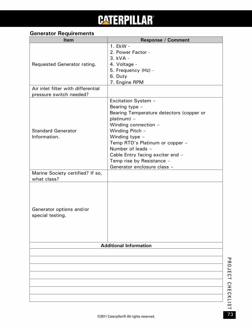
©2011 Caterpillar® All rights reserved. 73
PR
OJ
EC
T C
HE
CK
LIST
Generator Requirements Item Response / Comment
Requested Generator rating.
1. EkW - 2. Power Factor - 3. kVA - 4. Voltage - 5. Frequency (Hz) - 6. Duty 7. Engine RPM
Air inlet filter with differential pressure switch needed?
Standard Generator Information.
Excitation System – Bearing type – Bearing Temperature detectors (copper or platinum) – Winding connection – Winding Pitch – Winding type – Temp RTD’s Platinum or copper – Number of leads – Cable Entry facing exciter end – Temp rise by Resistance – Generator enclosure class –
Marine Society certified? If so, what class?
Generator options and/or special testing.
Additional Information

C175 PETROLEUM OFFSHORE PROJECT GUIDE
©2011 Caterpillar® All rights reserved. 74
PR
OJ
EC
T C
HE
CK
LIS
T
Special Testing Item Response / Comment
Testing requested. (Witness, marine society TVA, FEA and/or other.
Additional Information
Documentation Item Response / Comment
Project installation drawings required? (Mechanical, electrical and/or P&ID)
CERTS: IMO Emissions, Marine Society, etc….
Additional Information
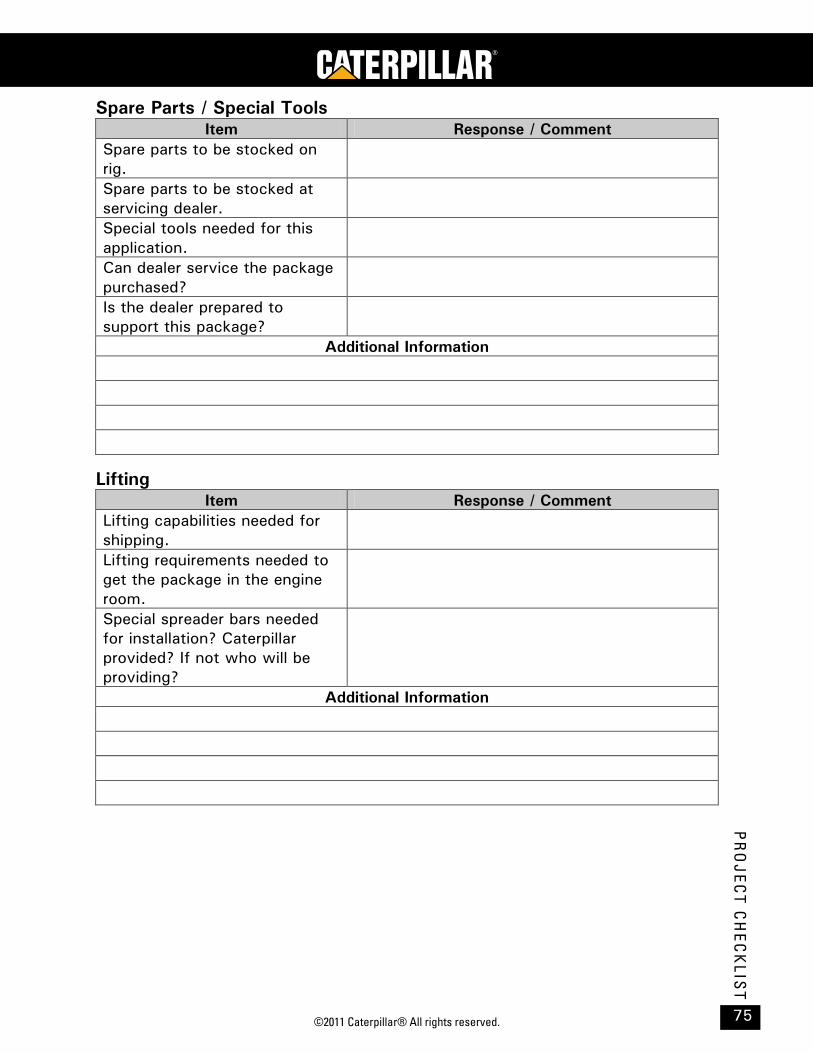
©2011 Caterpillar® All rights reserved. 75
PR
OJ
EC
T C
HE
CK
LIST
Spare Parts / Special Tools Item Response / Comment
Spare parts to be stocked on rig.
Spare parts to be stocked at servicing dealer.
Special tools needed for this application.
Can dealer service the package purchased?
Is the dealer prepared to support this package?
Additional Information
Lifting Item Response / Comment
Lifting capabilities needed for shipping.
Lifting requirements needed to get the package in the engine room.
Special spreader bars needed for installation? Caterpillar provided? If not who will be providing?
Additional Information

C175 PETROLEUM OFFSHORE PROJECT GUIDE
©2011 Caterpillar® All rights reserved. 76
PR
OJ
EC
T C
HE
CK
LIS
T
Training Item Response / Comment
Have dealer personnel (TC, mechanics, electricians, commissioning) been trained on package?
Have rig personnel (mechanics, electricians, commissioning) been trained on package to be used?
Additional Information
Signatures The following parties have discussed and agreed to the results and required
action during the design review process.
Customer Signature:
Date:
Dealer Signature:
Date:
A&I Engineer*:
Date:
* If the order is a Price List, an A&I engineer signature is not needed.

LEBW0010-00 ©2011 Caterpillar® Printed in U.S.A. All rights reserved.


![Caterpillar Industrial Engines Ratings Guide[1]](https://static.fdocuments.us/doc/165x107/55cf9dde550346d033af97e0/caterpillar-industrial-engines-ratings-guide1.jpg)