
201001-00367-00-EN-REP-0005 Rev 2 30 April FINAL · ndertake det r bores to en e constructi o...
64
Proposed Katherine to Gove Gas Pipeline Draft Environmental Impact Statement Water Resources Assessment Appendix B
Transcript of 201001-00367-00-EN-REP-0005 Rev 2 30 April FINAL · ndertake det r bores to en e constructi o...
Proposed Katherine to Gove Gas Pipeline Draft Environmental Impact Statement
Water Resources Assessment
Appendix B

PACIFIC ALUMINIUM
Katherine to Gove Gas Pipeline Water Resources Assessments
201001-00367 – 00-EN-REP-0005
29-April-13
Level 3, 60 Albert Street Brisbane QLD 4000 Australia Telephone: +61 7 3239 7400 Facsimile: +61 7 3221 7791 www.worleyparsons.com ABN 61 001 279 812 © Copyright 2013 WorleyParsons
WorleyParsonsresources & energy
KATHERINE TO GOVE GAS PIPELINE
WATER RESOURCES ASSESSMENTS
Disclaimer
This repoft has been prepared on behalf of and for the exclusive use of Pacific Aluminium, and issubject to and nsued in accordance with the agreement betvveen Pacific Aluminium andWorleyParsons. WorleyParsons accepts no liability or responsibility whatsoever for it in respect ofany use of or reliance upon this repoft by any third pafty.
Copying this repoñ without the permission of Pacific Aluminium or WorleyParsons r's nofpermitted.
PROJECT 2OIOO1-00367 - KATHERINE TO GOVE GAS PIPELINE
REV DESCRIPTION ORIG REVIEW DATE CLIENTAPPROVAL
DATE
2 lssued for Use a- N/A
A
Document No : 201001 EN-REP-OOOs
S 29April-13
Page ii
K
W
C
1
2
3
4
5
6
7
KATHERINE T
WATER RESO
Document NoRevision: 2
CONTEN
INT
Purp1.1
ABB
AVA
Data3.1
PRO
REL
SUR
Rain6.1
Soil6.2
Surf6.3
6.3.
6.3.
Was6.4
Imp6.5
Con6.6
6.6.
Cros6.7
6.7.
6.7.
6.7.
6.7.
Stor6.8
Man6.9
P6.10
C6.11
HYD
TO GOVE GAS
OURCES ASS
o.: 201001-00
TS
RODUCTION
pose of Repo
BREVIATION
AILABLE DA
a Limitations
OJECT WAT
LEVANT LEG
RFACE WAT
nfall .............
s and Topog
face Runoff .
1 Water st
2 Hydrote
stewater man
acts on Hydr
nstruction Im
1 Constru
ssing Constr
1 Horizont
2 Alternat
3 Trenche
4 Potentia
rmwater Man
nagement of
Proposed Mit
Conclusions .
DROGEOLO
S PIPELINE
ESSMENTS
0367-00-EN-R
N .................
ort ................
NS ................
ATA ...............
s ...................
TER SUPPLY
GISLATION .
TER ASSESS
....................
graphy ..........
....................
torages and
st water .......
nagement ....
rologic Regim
pacts – Strea
ction Progra
ruction Techn
tal Directiona
ives to HDD
ed Crossings
al Impacts on
nagement ....
Surface Wa
tigation Meas
....................
OGY ASSESS
REP-0005
....................
....................
....................
....................
....................
Y STRATEG
....................
SMENT .......
....................
....................
....................
drains .........
....................
....................
me of Waterc
am Crossing
am ................
niques .........
al Drilling .....
...................
s ...................
n Stream Hyd
....................
ater ...............
sures ...........
....................
SMENT .......
...................
...................
...................
...................
...................
Y ................
...................
...................
...................
...................
...................
...................
...................
...................
courses ......
gs ................
...................
...................
...................
...................
...................
draulics .......
...................
...................
...................
...................
...................
....................
....................
....................
....................
....................
....................
....................
....................
....................
....................
....................
....................
....................
....................
....................
....................
....................
....................
....................
....................
....................
....................
....................
....................
....................
....................
....................
...................
...................
...................
...................
...................
...................
...................
...................
...................
...................
...................
...................
...................
...................
...................
...................
...................
...................
...................
...................
...................
...................
...................
...................
...................
...................
...................
Page
.................. 1
.................. 1
.................. 4
.................. 5
.................. 5
.................. 6
.................. 8
................ 10
................ 10
................ 10
................ 11
................ 15
................ 16
................ 19
................ 19
................ 22
................ 22
................ 22
................ 22
................ 22
................ 23
................ 24
................ 24
................ 25
................ 26
................ 27
................ 29
e iii
4
5
5
6
8
0
0
0
5
6
9
9
2
2
2
2
2
3
4
4
5
6
7
9

K
W
8
A
A
A
A
KATHERINE T
WATER RESO
Document NoRevision: 2
Reg7.1
Gro7.2
7.2.
7.2.
7.2.
7.2.
Wat7.3
7.3.grou
Pote7.4
7.4.
7.4.
Reg7.5
CON7.6
7.6.
FUR7.7
REF
Appendice
APPENDIX 1
APPENDIX 2
APPENDIX 3
TO GOVE GAS
OURCES ASS
o.: 201001-00
gional Hydrog
undwater Ma
1 Daly Riv
2 Daly Riv
3 Proteroz
4 McArthu
ter supplies f
1 Water reundwater .....
ential environ
1 Acid Su
2 Potentia
gulatory requ
NCLUSIONS
1 Identifie
RTHER INVE
FERENCES
es
- SURFACE
- EXISITING
- ACID SUL
S PIPELINE
ESSMENTS
0367-00-EN-R
geology .......
anagement U
ver Basin –T
ver Basin – J
zoic Sedimen
ur Basin........
for proposed
equirements ....................
nmental risks
lfate Soils (A
al environme
irements for
S ...................
d Risks ........
ESTIGATION
....................
E WATER MA
G GROUNDW
LFATE SOILS
REP-0005
....................
Units (GMUs
indall Limest
Jinduckin For
ntary GMUs
....................
d KGGP cons
for KGGP p....................
s from KGGP
ASS) ............
ntal receptor
r the Take, U
....................
....................
NS ...............
....................
APS
WATER BOR
S RISK MAP
...................
s) .................
tone ............
rmation .......
(North East
...................
struction ......
ipeline infras...................
P developme
...................
rs ................
se or Dispos
...................
...................
...................
...................
RES ALONG
P RESULTS
....................
....................
....................
....................
NT, Bulman
....................
....................
structure: Pot....................
ent ...............
....................
....................
sal of ground
....................
....................
....................
....................
G THE KGGP
...................
...................
...................
...................
& Adelaide
...................
...................
otential sourc...................
...................
...................
...................
dwater .........
...................
...................
...................
...................
P
Page
................ 29
................ 32
................ 32
................ 33
River) ...... 33
................ 33
................ 34
ce of ................ 35
................ 38
................ 38
................ 39
................ 39
................ 40
................ 41
................ 43
................ 46
e iv
9
2
2
3
3
3
4
5
8
8
9
9
0
3
6

K
W
1
PreTlo
Pfupg
TAK3locopcoe
1
Tre
B
Im
KATHERINE T
WATER RESO
Document NoRevision: 2
INT
Pacific Aluminefinery at Go
Territory. Theocations for s
Power and steuel oil. In ordroposed to pas will help u
The KatherineAmadeus GasKGGP would
00mm and aocations alonompressor srocessing ofonstruction cquipment ac
Pu.1
This report haequirements
Baseline
mpacts
TO GOVE GAS
OURCES ASS
o.: 201001-00
TRODUC
nium (a businove, 650 kilome Gove minesmelting and
eam for the Gder to reduceprovide the faunderpin the
e to Gove Gas Pipeline atbe a high pr
a design openg the route station. The f gas would bcorridor and wccess tracks
urpose o
as been prepof the EIS g
Provide a bartificial, epimpacted bdrainage pa
Provide a daffected by
Provide detand bank plocations. Inpipeline, in work.
Describe hodescribed a
Detail the eDescribe th
S PIPELINE
ESSMENTS
0367-00-EN-R
TION
ness unit of Rmetres (km)
e and refinery further proc
Gove Refinee fuel oil conacility with nalong term op
as Pipeline (a point appr
ressure, steerating life of such as metsupplied gasbe required. would includto facilitate c
f Report
pared to Paciuidelines:
broad descripphemeral or py the projectatterns, flow,
description ofy the undergr
tails of the poprofiles and dnclude informparticular th
ow the pipeliabove.
extent of de-whe potential im
REP-0005
Rio Tinto) oweast of Darwy produce higcessing.
ery and mininsumption anatural gas asperating viab
KGGP) is prroximately 20el pipeline ap50 years. It tering facilities from the AmThe pipeline
de supportingconstruction
t
ific Aluminium
ption of any wpermanent, it. Include a d, likelihood o
f relevant groround pipes a
otential locatdescribe selemation on thehe timing (and
ine might imp
watering thatimpacts inclu
wns and opewin in north egh grade alu
ng operationsnd improve os an alternatibility of the R
oposed to de0 km south o
pproximately will also incl
es, scraper smadeus Pipee would be cg infrastructuactivities.
m to support
waterways oincluding sprdescription ofof flooding an
oundwater reand excavati
tions of pipelection criteriae flow regimed volume) of
pact on the s
t may be requding the effe
rates a bauxeast Arnhem mina which i
s are currentperating costve fuel sourc
Refinery.
eliver naturalof Katherine, 603 km longude above g
stations, maineline is sales onstructed wre such as te
t the draft EIS
r other wetlarings and mof catchment s
nd present wa
esources in aion.
line waterwaa for determine of the watef flows in rela
surface and g
quired for instects of localis
xite mine andLand, Northis then shipp
tly generatedts at the Refce. The lowe
l gas from thto the Gove
g with a nomground facilitnline valves quality so n
within a 30 memporary wo
S and addres
and habitat, nound springssystems, exi
water uses.
any areas lik
ay crossings ning the finalerways in theation to any c
ground wate
tallation of thsed lowering
Pag
d alumina ern
ped to other
d from importfinery, it is er cost natur
he existing NT Refinery. Tinal diameteries at specifiand a o additional
m wide ork camps an
ss the releva
natural or , that may beisting surface
kely to be
including bel crossing
e vicinity of thconstruction
r features
he pipeline. g of
e 1
ted
ral
T The r of ic
nd
ant
e e
d
he

KATHERINE TO GOVE GAS PIPELINE
WATER RESOURCES ASSESSMENTS
Document No.: 201001-00367-00-EN-REP-0005 Page 2 Revision: 2
groundwater tables (ie, zone of influence), associated disturbance to wetland and aquatic flora and fauna (if any).
Provide details of typical waterway crossings that would be constructed and likely
impacts associated with crossing at each intended location. Consider and discuss the
risks associated with the proximity of the proposed condensate pipeline to borefields or aquifer recharge zones that may supply potable water.
Detail the potential impacts from wastewater generated by construction/operational water use including translocation or introduction of non-endemic aquatic fauna and flora.
Management Detail safeguards and management strategies used to minimise the impacts of pipeline
construction and operation on the hydrological features described above. In particular, provide details on the following:
o Measures to safeguard surface and groundwater resources including options for the
appropriate treatment and disposal of construction and operational wastewater, and discharge of abstracted water. Identify the preferred option and the selection criteria use.;
o Measures to ensure the beds and banks of water courses remain stable and protected from the natural forces of erosion as required, incorporating preferred methodologies of DLRM (Department of Land and Resource Management) where
practicable particularly where there has been any disturbance to the bank or to the bed.
o Measures to safeguard downstream water quality including appropriate
management of any acid sulphate soils excavated and wetland crossings.
This report discusses the potential risks (if any) caused to surface water systems (major and minor watercourses) and groundwater assets as a result of the construction and operation of the KGGP. The risks and mitigation measures discussed in this report include:
Land clearing for the right of way and topsoil stockpiling;
Disturbances to waterways due to construction activities where the pipelines cross water courses;
Negative changes to the hydrologic regime of watercourses as a result of surface water abstraction to meet construction water requirements (e.g. to supply water for potable water for camps, dust suppression, hydrostatic pressure testing of pipeline infrastructure);
Increased erosion and sediment generation due to construction activities;
Impact on water quality due to discharge of pressure test water and sewerage effluent from construction camps; and
Fuel and chemical storage and waste disposal during pipeline construction and operation.

KATHERINE TO GOVE GAS PIPELINE
WATER RESOURCES ASSESSMENTS
Document No.: 201001-00367-00-EN-REP-0005 Page 3 Revision: 2
This report is structured to address the assessment of surface water and groundwater issues of the draft EIS.
1. Section 6 Surface Water Assessment and 2. Section 7 Hydrogeology Assessment.
KATHERINE TO GOVE GAS PIPELINE
WATER RESOURCES ASSESSMENTS
Document No.: 201001-00367-00-EN-REP-0005 Page 4 Revision: 2
2 ABBREVIATIONS
ASS Acid Sulfate Soils
BoM Bureau of Meteorology
DLRM Department of Land and Resource Management
EIS Environmental Impact Statement
ESCP Erosion and Sediment Control Plan
GDE Groundwater Dependent Ecosystems
GL Gigalitres
GMU Groundwater Management Units
HDD Horizontal Directional Drilling
KGGP Katherine to Gove Gas Pipeline
RoW Right of Way
SWMP Stormwater Management Plan
TDS Total Dissolved Solids
UA Unincorporated Area
WAP Water Allocation Plan
WCD Water Control District
K
W
3
T
3
ABwuoth
Nres2se
It a
KATHERINE T
WATER RESO
Document NoRevision: 2
3 AV
The assessm
Climati
Stream
Report
Report
Trans T(TTP, 2
Impactsof Draft
Report
Report
Report
Da3.1
Available streBoM databaswater and gro
ndertake detr bores to en
he constructi
No detailed sueport, so deturface water0km of the Reason surve
t is proposednd data colle
TO GOVE GAS
OURCES ASS
o.: 201001-00
VAILABLE
ent of surfac
c data obtain
mflow data fro
‘North Austr
‘North Austr
Territory Und2004).
s on Hydrolot EIS (EWLS
‘Water Reso
‘Jawoyn wa
‘Water Reso
ta Limita
eamflow dataes. The data
oundwater retailed assessnable quantiton period.
urvey of the ailed descriprs were not aRoW with a vy during 201
d that appropection.
S PIPELINE
ESSMENTS
0367-00-EN-R
E DATA
ce water and
ned from the
om the Depa
ralian Sustain
ralian Sustain
derground Pi
ogy & Water S, 2004).
ources of We
ter study’ (D
ources of Ea
ations
a has been soa available wesources. It wsments of thetative guideli
pipeline RoWptions of wateable to be proview to identif
3.
riate manage
REP-0005
groundwate
Bureau of M
rtment of La
nable Yields
nable Yields
peline Wade
Quality from
est Arnhem L
. George, 20
st Arnhem L
ourced from was sufficient was not posse volumes ofnes to be de
W (Right of Werway crossiovided. It is hfying which o
ement plans
er issues has
Meteorology
nd and Reso
’ (CSIRO, 20
’ (CSIRO, 20
eye to Gove
the Trans T
Land’ (U. Zaa
001).
and’ (U. Zaa
DLRM and rto derive a g
sible during thf water that c
eveloped for
Way) has beeings and locahowever, inteof these may
will be prep
s been based
(BoM, 2013)
ource Manag
009).
009).
in the Northe
erritory Pipe
ar, 2003).
ar, G. Prowse
rainfall data hgeneral undehe design phcan be obtainmanagemen
en undertakeations of propended to ideny be suitable
ared followin
d on the follo
).
gement (DLR
ern Territory
eline Project –
e and I. Matt
has been soerstanding ofhase of the pned from indnt of water re
en at the timeposed extracntify all boresfor use durin
ng additional
Pag
wing:
RM, 2013).
– Draft EIS,
– Appendix G
hews, 1999)
urced from f the surface
project to ividual streasources duri
e of writing thctions from s drilled withng the dry
investigation
e 5
G
).
ms ing
his
in
n

KATHERINE TO GOVE GAS PIPELINE
WATER RESOURCES ASSESSMENTS
Document No.: 201001-00367-00-EN-REP-0005 Page 6 Revision: 2
4 PROJECT WATER SUPPLY STRATEGY
Construction of the gas pipeline has the potential to impact on surface water and groundwater resources due to:
Extractions of water required for construction activities; and
Physical changes to waterways and topography along the right of way (ROW).
Water is required for the following construction activities:
Potable water for construction camps;
Hydrotesting of pipeline;
HDD (Horizontal Directional Drilling) creek crossings;
Dust suppression;
Compaction of trench backfill; and
Washdown of vehicles and other miscellaneous purposes.
The projected water usage for the construction period is summarized in Table 4-1.
Table 4-1 Projected Water Usage During Construction Period
Activity Volume (ML) Daily Demand (kL/d)
Camps Potable Water 50 300
Hydrotesting 24-46 variable
HDD 0.77 23
Dust suppression 132 800
Miscellaneous uses Minor <2
In order to satisfy the projected water usage, it is proposed to extract water from surface water sources where practicable and sustainable, with minor supplementary extraction from groundwater via existing or new bores, where practicable and sustainable.
The Australian Drinking Water Guidelines (ADWG, 1996) states that good drinking water has a TDS of less than 500mg/L, and that a TDS of 500 – 1000 mg/L is acceptable according to taste, while TDS greater than 1000mg/L may be associated with excessive scaling, corrosion and unsatisfactory taste.
The limited water quality data available for surface waters in the Roper River Basin and other river basins in West Arnhem Land indicate TDS generally less than 500mg/L, total alkalinity less than 300 mg/L and pH of 6.1-8.2. Therefore, it is anticipated that water extracted from surface water resources will require sterilisation and minimal treatment for potable use.
KATHERINE TO GOVE GAS PIPELINE
WATER RESOURCES ASSESSMENTS
Document No.: 201001-00367-00-EN-REP-0005 Page 7 Revision: 2
In general, the groundwater naturally has a low pH, caused by high levels of dissolved carbon dioxide and can be treated by aeration as is done for the Nhulunbuy water supply (U. Zaar et. al., 1999). Additionally groundwater in West Arnhem Land, which represents approximately half of the pipeline route, has been assessed as suitable for potable use without treatment (U. Zaar, 2003). It is anticipated that water extracted from groundwater bores will require sterilisation and minimal treatment for potable use. Section 6.3.2 of the hydrogeological assessment provides further details of groundwater quality.
The projected construction and camp, non-potable water use includes dust suppression, access track maintenance, vehicle wash-down and other ancillary purposes. It is anticipated that water extracted for non-potable uses, excluding hydrotest water, will not require any treatment. Hydrotest water use and disposal is discussed below in 6.3.2.
If an adequate supply of water cannot be obtained locally from surface water or groundwater, it will be necessary to transport water from other sources. In particular, it may be necessary to transport potable water from Katherine and Gove if the extracted surface water or groundwater quality is not able to be easily treated to potable quality.
The strategy for water supply during the construction period has not been finalised at this time due to insufficient information on flows and water quality available from surface water and groundwater resources, as discussed in 3.1.
Additional investigations of the ‘dry’ season flow behaviour of the surface watercourses and baseflow from groundwater are to be undertaken in order to derive trigger and threshold criteria for appropriate management of extractions from surface water or groundwater sources. The additional investigations may include hydrologic and hydrogeologic modelling and the installation of temporary stream and borehole monitoring equipment to record water levels and selected quality parameters.
KATHERINE TO GOVE GAS PIPELINE
WATER RESOURCES ASSESSMENTS
Document No.: 201001-00367-00-EN-REP-0005 Page 8 Revision: 2
5 RELEVANT LEGISLATION
The management and protection of water resources in the Northern Territory is controlled under the Water Act 2011 (hereafter The Water Act). The Water Act governs the extent to which both surface and groundwater can be used, and for what purpose. For example, waste discharge to natural waters is prohibited unless licensed under the Water Act. Waste Discharge Licences are only available in areas where Beneficial Uses have been declared. If waste is to be discharged to a waterway in areas where no such declaration has been made, the Beneficial Uses must be determined and declared prior to licence issue. This process is normally done in full consultation with the community and as such, may be prohibitive from a timing perspective. With reference to Subsection (3) of the Water Act, Beneficial Uses mean the uses of water. The following are Beneficial Uses of water:
Agriculture – to provide irrigation water for primary production including related research;
Aquaculture – to provide water for commercial production of aquatic animals including related research;
Public water supply – to provide source water for drinking purposes delivered through community water supply systems;
Environment – to provide water to maintain the health of aquatic ecosystems;
Cultural – to provide water to meet aesthetic, recreational and cultural needs;
Industry – to provide water for industry, including secondary industry and a mining or petroleum activity, and for other industry uses not referred to elsewhere in this subsection; and
Rural stock and domestic – to provide water for the purposes permitted under sections 10, 11 and 14.
Under Part 3, Division 1 of the Water Act, various stipulations are made for the control, protection and management of water resources. For example, under Section 22A and 22B of the Water Act, Beneficial uses within Water Control Districts (WCD) are described. At present the only WAP present on the KGGP route is in the Daly River Basin; forming the Daly-Roper WCD.
The Northern Territory Water Act (2011) prohibits the unauthorised taking or use of surface water and unlicensed extraction of groundwater. Under the Act, the Administrator may, on the recommendation of the Minister, by notice in the Gazette, declare that a licence is not required for the taking or use of surface water of a class, kind, description or volume, or at a rate or for a purpose, specified in the notice. Additionally, the Administrator may, on the recommendation of the Minister, by notice in the Gazette, declare that a provision of the Act does not apply to or in relation to a bore, or to drainage water or waste, of a class or description specified in the notice.
KATHERINE TO GOVE GAS PIPELINE
WATER RESOURCES ASSESSMENTS
Document No.: 201001-00367-00-EN-REP-0005 Page 9 Revision: 2
Section 7 of the Water Act, however states that:
7 Application of Act to mining or petroleum activity
(1) Section 15 does not apply to an interference with, or the obstruction of, a waterway if the interference or obstruction occurs in the course of a mining or petroleum activity.
(2) Section 16 does not apply to waste that comes into contact with water, or water that is polluted, if:
(a) the contact or pollution occurs in the course of carrying out a mining or petroleum activity; and
(b) the waste or polluted water is confined within the mining site or petroleum site on which the activity is being carried out.
(3) Subject to subsection (4), Parts 5 and 6 do not apply to an action or omission by a person, or to an action or omission caused, suffered or permitted by a person to be done, or to be omitted to be done, by another person, if the action or omission occurs in the course of carrying out a mining or petroleum activity.
(4) Part 6, Division 5 applies to the disposal underground of waste in the course of carrying out a mining or petroleum activity on a mining site or petroleum site if the waste is not confined within the mining site or petroleum site.
Section 15 refers to the obstruction or interference with a waterway; Section 16 refers to the prohibition of pollution; Part 5 refers to surface water works and extraction and Part 6 refers to Groundwater works and extraction.
Consequently, no licenses for extraction of surface or groundwater will be required. It should be noted; however, that this exemption does NOT extend to Section 16 which requires that a waste discharge licence be obtained prior to the discharge of any contaminated water directly into surface or groundwater.

K
W
6
6
TAMsoa
T
P
A
6
Tgd
KATHERINE T
WATER RESO
Document NoRevision: 2
6 SU
Ra6.1
The area encAustralia, withMarch. Annuaouthern sectre summariz
Table 6-1 An
Period
Ra
(mm
Jan 426
Feb 374
Mar 321
Apr 101
May 21.
Jun 1.9
Jul 1.2
Aug 5.0
Sep 15.
Oct 70.
Nov 139
Dec 251
Annual 1729
So6.2
The region coranitic in origeposited on
TO GOVE GAS
OURCES ASS
o.: 201001-00
URFACE W
infall
ompassing th approximatal rainfall vartion. Rainfall zed in Table
nual Rainfa
Darwin
in
m)
Pot. E
(mm
6.6 186
4.3 159
.3 176
.2 189
.2 210
9 204
2 210
0 223
.7 228
.2 248
9.3 222
.3 204
9.3 2462
ils and T
ontains rocksgin and undetop of these
S PIPELINE
ESSMENTS
0367-00-EN-R
WATER A
he KGGP rotely 90% of aries from up tand evapora6-1.
ll and Poten
Evap.
m)
Rai
(mm
6.0 275
9.6 283
6.7 274
9.0 228
0.8 89.
4.0 31.
0.8 18.
3.2 5.5
8.0 5.8
8.0 11.
2.0 44.
4.6 181
2.7 1461
Topograp
s from the Mcerlie most of t
granites to f
REP-0005
ASSESS
oute is locateall rain fallingto 1,800mm ation data re
ntial Evapor
Gove
in
m)
Pot. Ev
(mm
5.0 176
.2 156
.5 155
.8 159
7 167
1 156
4 161
5 189
8 201
4 223
4 219
.2 207
1.7 2171
phy
cArthur Basinthe region. Sform the Arn
MENT
d within the g during the win the northecorded at Bu
ration
vap.
m)
Rai
(mm
.7 261.
.0 246.
.0 204.
.0 44.3
.4 5.1
.0 0.4
.2 1.1
.1 1.7
.0 6.8
.2 33.2
.0 88.0
.7 223.
1.3 1133
n and the ArStrata of the hem Land P
tropical monwet season bern section toureau of Met
Katherine
n
m)
Pot. Ev
(mm
.9 161.
.0 156.
.2 173.
3 183.
173.
4 147.
170.
7 201.
8 228.
2 244.
0 222.
.9 189.
3.0 2250
afura Basin. Kombolgie Slateau; this fe
nsoonal belt obetween Novo less than 9teorology (Bo
vap.
m)
Rain
(mm
.2 182.8
.0 176.5
.6 174.8
.0 55.9
.6 10.7
.0 5.1
.5 1.1
.5 0.7
.0 1.8
.9 13.5
.0 42.4
.1 131.6
0.4 815.5
The oldest rSandstone hafeature domin
Page
of northern vember and 900mm in theoM) stations
Ngukurr
n
m)
Pot. Ev
(mm)
8 182.9
5 170.8
8 173.6
9 183.0
7 173.6
159.0
170.5
207.7
231.0
5 272.8
4 255.0
6 226.3
5 2406.2
rocks are ave been nates the
10
e
ap.
)
9
8
6
0
6
0
5
7
0
8
0
3
2

K
W
reu
Sa
6
TRbRb(DRra1ing
TDDs
T
Smlagflop
KATHERINE T
WATER RESO
Document NoRevision: 2
egional landsndermining e
Soils are mosnd alluvial so
Su6.3
The pipeline pRiver basin, th
etween KathRoper River d
asins drain nDwg 201001
River basin arainfall (appro800mm) (Bo
n Table 6-1. Preater than a
The streamfloDepartment oDLRM are shhown on Fig
Table 6-2 Str
Gauge ID
G8250002
G8260053
G8260219
G9030003
G9030088/9
Surface runofmost watercoarger rivers aroundwater. ow) of the murposes alon
TO GOVE GAS
OURCES ASS
o.: 201001-00
scape. The seffect of wav
stly skeletal ooils on the flo
rface Ru
passes throuhe central poherine and Gdrains eastwanorthwards to-00367-GIS-re located soox. 800-1100oM, 2013), wPotential evaannual rainfa
ow characterof Land Resoown in Tableure 6-2 (Dwg
reamflow Da
Stream
Goyder Rive
Latram Rive
Giddy River
Wilton River
WaterhouseRiver
ff is generallyurses ceasin
are ‘permaneSection 7.3.
major river sysng the KGGP
S PIPELINE
ESSMENTS
0367-00-EN-R
sandstone clive erosion at
or stony on thoodplains. A
unoff
ugh the uppeortion of the Gove. The Daards to the Go the Arafura-SKT-019 incouth of the A0mm) than thith the bulk oaporation is aall.
istics of the wource Manage 6-2, with gag 201001-00
ata Summar
Period oRecord
er 1/9/67 –1/9/02
er 1/11/63 –1/11/85
1/9/71 –1/11/86
r 1/9/67 –1/6/78
e 1/12/60 –1/8/04
y limited to thng to flow duent’ streams, 1 and Table stems whereP route.
REP-0005
iffs of the Arntheir base d
he hills and ppproximately
er section of tGoyder Rive
aly River basGulf of Carpea Sea. The mcluded in App
Arnhem Land he northern bof the rainfallapprox. 2200
watercoursegement (DLRauging statio0367-GIS-SK
ry
of d
Mean ADisch(ML/y
– 788
– 5
25,2
– 6
44,
– 505
– 239
he wet summring the mid with dry sea 6-1 discuss
e surface wat
nhem Land eduring a perio
plateau, withy one-third of
the Daly Riveer basin and in drains wes
entaria and thmajor drainagpendix 1).ThPlateau and
basins draininl occurring be0-2500mm/ye
s traversed dRM) gauging ons that are loKT-017 includ
Annual harge year)
A(
,940 5
230
150
,000 4
,760 3
mer monsoonto late dry se
ason flow beis the basefloter is propos
escarpment wod of high oc
shallow siltyf the Arnhem
er basin, the the upper Bustwards to thhe Goyder Rge basins aree upper Daly
d receive signng to the Araetween Octoear over the
derive from sstations. Sumocated closeded in Appen
Area km2)
Ru(mm
5,440 1
85 2
111 5
4,480 1
3,110
n season (Deeason (July tng basefloww characteried to be extr
were formedcean levels.
y soils, somem Plateau is b
northern pauckingham Rhe Timor Sea
River and Buce presented y River basinnificantly low
afura Sea (apober and Apr
region and i
streamflow remmarised ree to the pipelndix 1).
unoff m/year)
MF(m
136 1
293
552
112 2
73 1
ecember to Mto Novembe
w supplied froistics (estimaracted for co
Page
d by the
e deep sandsbare rock.
rt of the RopRiver basin a, while the ckingham Rivon Figure 6-n and Roper wer annual pprox. 1500-ril, as presens significantl
ecords at thesults from thine route
Max. Flow m3/s)
MiFlo(L/
,413 183
142 65
617 18
2,253 14
,771 <1
March), with r). Only the
om ated minimumonstruction
11
s
per
ver 1
ted ly
e he
n. ow /s)
30
5
8
4
10
m

KATHERINE TO GOVE GAS PIPELINE
WATER RESOURCES ASSESSMENTS
Document No.: 201001-00367-00-EN-REP-0005 Page 12 Revision: 2
Figure 6-1 Major Drainage Basins
KATHERINE TO GOVE GAS PIPELINE
WATER RESOURCES ASSESSMENTS
Document No.: 201001-00367-00-EN-REP-0005 Page 13 Revision: 2
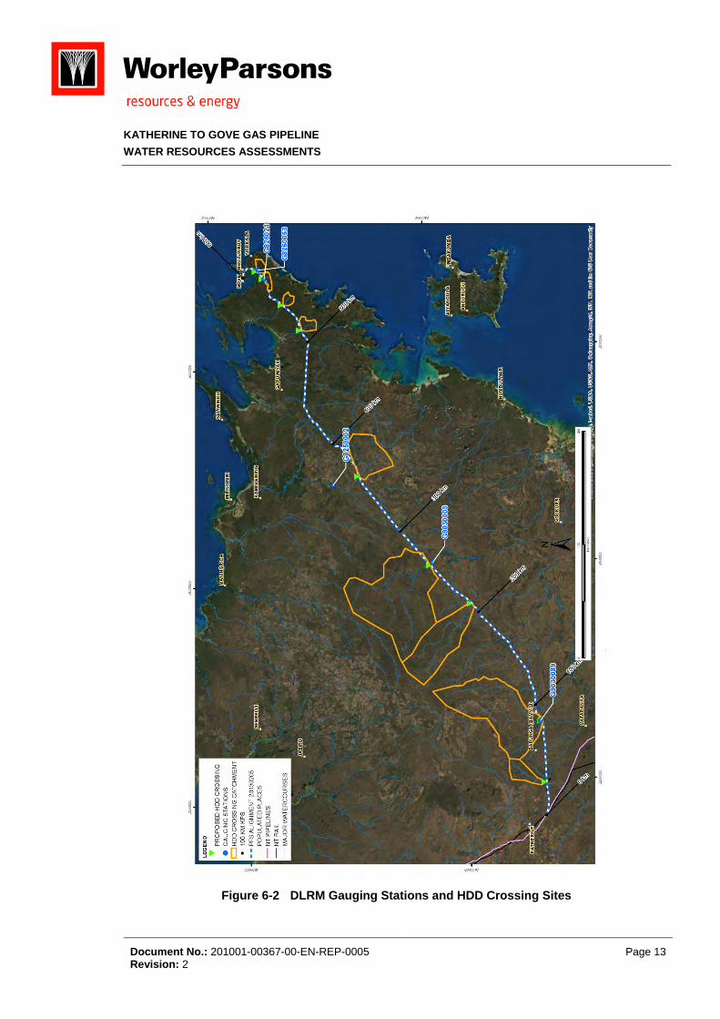
Figure 6-2 DLRM Gauging Stations and HDD Crossing Sites
KATHERINE TO GOVE GAS PIPELINE
WATER RESOURCES ASSESSMENTS
Document No.: 201001-00367-00-EN-REP-0005 Page 14 Revision: 2
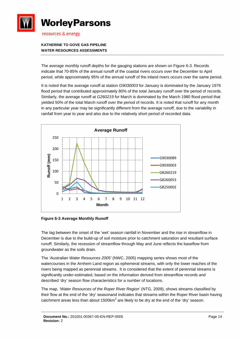
The average monthly runoff depths for the gauging stations are shown on Figure 6-3. Records indicate that 70-85% of the annual runoff of the coastal rivers occurs over the December to April period, while approximately 95% of the annual runoff of the inland rivers occurs over the same period.
It is noted that the average runoff at station G9030003 for January is dominated by the January 1976 flood period that contributed approximately 80% of the total January runoff over the period of records. Similarly, the average runoff at G260219 for March is dominated by the March 1980 flood period that yielded 50% of the total March runoff over the period of records. It is noted that runoff for any month in any particular year may be significantly different from the average runoff, due to the variability in rainfall from year to year and also due to the relatively short period of recorded data.
Figure 6-3 Average Monthly Runoff
The lag between the onset of the ‘wet’ season rainfall in November and the rise in streamflow in December is due to the build-up of soil moisture prior to catchment saturation and resultant surface runoff. Similarly, the recession of streamflow through May and June reflects the baseflow from groundwater as the soils drain.
The ‘Australian Water Resources 2005’ (NWC, 2005) mapping series shows most of the watercourses in the Arnhem Land region as ephemeral streams, with only the lower reaches of the rivers being mapped as perennial streams. It is considered that the extent of perennial streams is significantly under-estimated, based on the information derived from streamflow records and described ‘dry’ season flow characteristics for a number of locations.
The map, ‘Water Resources of the Roper River Region’ (NTG, 2009), shows streams classified by their flow at the end of the ‘dry’ seasonand indicates that streams within the Roper River basin having catchment areas less than about 1500km2 are likely to be dry at the end of the ‘dry’ season.
0
50
100
150
200
250
1 2 3 4 5 6 7 8 9 10 11 12
Ru
no
ff (
mm)
Month
Average Runoff
G9030089
G9030003
G8260219
G8260053
G8250002
KATHERINE TO GOVE GAS PIPELINE
WATER RESOURCES ASSESSMENTS
Document No.: 201001-00367-00-EN-REP-0005 Page 15 Revision: 2
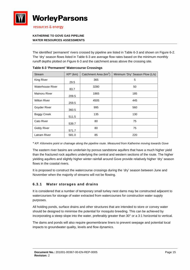
The identified ‘permanent’ rivers crossed by pipeline are listed in Table 6-3 and shown on Figure 6-2. The ‘dry’ season flows listed in Table 6-3 are average flow rates based on the minimum monthly runoff depths plotted on Figure 6-3 and the catchment areas above the crossing site.
Table 6-3 ‘Permanent’ Watercourse Crossings
Stream KP* (km) Catchment Area (km2) Minimum ‘Dry’ Season Flow (L/s)
King River 29.5
365 5
Waterhouse River 83.7
3280 50
Mainoru River 209.5
1865 185
Wilton River 259.5
4505 445
Goyder River 360.5
995 560
Boggy Creek 511.5
135 130
Cato River 539.7
80 75
Giddy River 571.7
80 75
Latram River 581.0 85 220 * KP: Kilometre point or chainage along the pipeline route. Measured from Katherine moving towards Gove
The eastern river basins are underlain by porous sandstone aquifers that have a much higher yield than the fractured rock aquifers underlying the central and western sections of the route. The higher yielding aquifers and slightly higher winter rainfall around Gove provide relatively higher ‘dry’ season flows in the coastal rivers.
It is proposed to construct the watercourse crossings during the ‘dry’ season between June and November when the majority of streams will not be flowing.
6.3.1 Water storages and drains
It is considered that a number of temporary small turkey nest dams may be constructed adjacent to watercourses for storage of water extracted from watercourses for construction water supply purposes.
All holding ponds, surface drains and other structures that are intended to store or convey water should be designed to minimise the potential for mosquito breeding. This can be achieved by incorporating a steep slope into the water, preferably greater than 30° or a 3:1 horizontal to vertical.
The dams and ponds will also require geomembrane liners to prevent seepage and potential local impacts to groundwater quality, levels and flow dynamics.
KATHERINE TO GOVE GAS PIPELINE
WATER RESOURCES ASSESSMENTS
Document No.: 201001-00367-00-EN-REP-0005 Page 16 Revision: 2
6.3.2 Hydrotest water
Hydrostatic pressure testing (hydrotesting) of the pipeline will be undertaken in accordance with the requirements of Pipelines - Gas and Liquid Petroleum Field Pressure Testing (AS2885.5:2012). Australian Standards 2885.5:2012 focuses on assessing the structural integrity of the pipeline and does not address the potential issues with the release of poor quality hydrotest water to environmental receptors (i.e. groundwater). For example, biocides and oxygen scavengers are often required to be added to the hydrotest water to prevent corrosion of the pipeline. Disposal of hydrotest water is recommended to be in accordance with Australian Pipeline Industry Association (APIA) Code of Environmental Practice (APIA, 2009).
6.3.2.1 VOLUMES
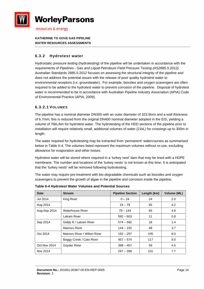
The pipeline has a nominal diameter DN300 with an outer diameter of 323.9mm and a wall thickness of 6.7mm; this is reduced from the original DN400 nominal diameter adopted in the EIS, yielding a volume of 76kL/km for hydrotest water. The hydrotesting of the HDD sections of the pipeline prior to installation will require relatively small, additional volumes of water (21kL) for crossings up to 300m in length.
The water required for hydrotesting may be extracted from ‘permanent’ watercourses as summarised below in Table 6-4. The volumes listed represent the maximum volumes without re-use, excluding allowance for evaporation and other losses.
Hydrotest water will be stored where required in a ‘turkey nest’ dam that may be lined with a HDPE membrane. The number and locations of the ‘turkey nests’ is not known at this time. It is anticipated that the ‘turkey nests’ will be removed following hydrotesting.
The water may require pre-treatment with bio-degradable chemicals such as biocides and oxygen scavengers to prevent the growth of algae in the pipeline and corrosion inside the pipeline.
Table 6-4 Hydrotest Water Volumes and Potential Sources
Date Stream Pipeline Section Length (km) Volume (ML)
Jul 2014 King River 0 – 24 24 2.0
Aug 2014 24 – 79 55 4.2
Aug-Sep 2014 Waterhouse River 79 – 144 65 4.9
Latram River 592 – 603 11 0.8
Sep 2014 Giddy R / Latram River 574 – 592 18 1.4
Mainoru River 144 – 192 48 3.7
Oct 2014 Mainoru River / Wilton River 192 – 297 105 8.0
Boggy Creek / Cato River 457 – 574 117 9.0
Oct-Nov 2014 Goyder River 398 – 457 59 4.5
Nov 2014 297 – 398 101 7.7

KATHERINE TO GOVE GAS PIPELINE
WATER RESOURCES ASSESSMENTS
Document No.: 201001-00367-00-EN-REP-0005 Page 17 Revision: 2
It is proposed to hydrotest the pipeline in 11 sections, varying in length from 11km up to 117km. Therefore, the volumes of water required for hydrotesting range from approximately 0.8ML up to 8.9ML. It is anticipated that hydrotest water may be re-used to test successive sections of pipeline, thereby reducing the volume of water required for hydrotesting from approximately 46ML without re-use to 24ML with maximum re-use.
It is noted that the hydrotest water volumes listed in Table 6-4 represent the volumes required with no re-use plus 20% allowance for evaporation losses.
The proposed re-use of hydrotest water may result in the transfer of relatively minor volumes of water, generally less than 5ML, from one local catchment to another local catchment. The small volumes of water transferred and short durations of released hydrotest water are considered unlikely to impact local hydrologic behaviour significantly.
6.3.2.2 DISPOSAL
It is proposed to dispose of hydrotest water by land application to stable (rocky) vegetated areas to minimise direct impacts on surface water quality and wetland environments. If a suitable site for land disposal cannot be located within an acceptable distance of the pipeline or with negotiated access, the hydrotest water may be disposed via evaporation pond.
It is noted that potential evaporation over the July to November period is approximately 1150mm and average rainfall for the same period is approximately 100mm. Therefore, evaporation ponds should not exceed 1.0m in depth in order to maximise the opportunity for hydrotest water to evaporate before the onset of the monsoon rainfall season. Therefore, the surface area of any evaporation pond is expected to be less than 1 ha, based on a maximum 9ML volume of hydrotest water to be disposed from any section of pipeline, as listed in Table 6-4. As stated above in Section 5.3.1, the evaporation ponds will require geomembrane or clay liners to prevent seepage and potential local impacts to groundwater quality, levels and flow dynamics.
Research undertaken on the disposal of water used for hydrostatic testing of pipelines has revealed the following:
The hydro-test water contains contaminants that may require treatment prior to disposal;
The contaminants for new pipelines are mainly due to mill scale breakdown and unreacted; additives and their reaction products;
The contaminant levels are generally not toxic;
The characteristics of the disposal site play a role in determining the treatment required;
Special planning is required when biocides are used and when the source water itself presents a disposal problem; and
The discharge of hydrotest water is a one-off event and this should be considered when evaluating the potential environmental impact.
KATHERINE TO GOVE GAS PIPELINE
WATER RESOURCES ASSESSMENTS
Document No.: 201001-00367-00-EN-REP-0005 Page 18 Revision: 2
Treatment of hydrotest water for disposal may comprise one or more of the following:
Discharge onto geofabric to trap sediment and minimise erosion;
Holding ponds for settling of sediments; and
Chemical treatment and absorption of organic pollutants with activated carbon.
The complexity of the treatment process depends on the characteristics of the hydrotest water, with simpler treatment generally being required for new pipelines.
The release of water to land should be carried out in a manner that ensures:
Vegetation is not damaged;
Soil erosion and soil structure damage is avoided;
No surface ponding of released water occurs;
The quality of groundwater is not adversely affected; and
No release of water to any surface waters occurs.
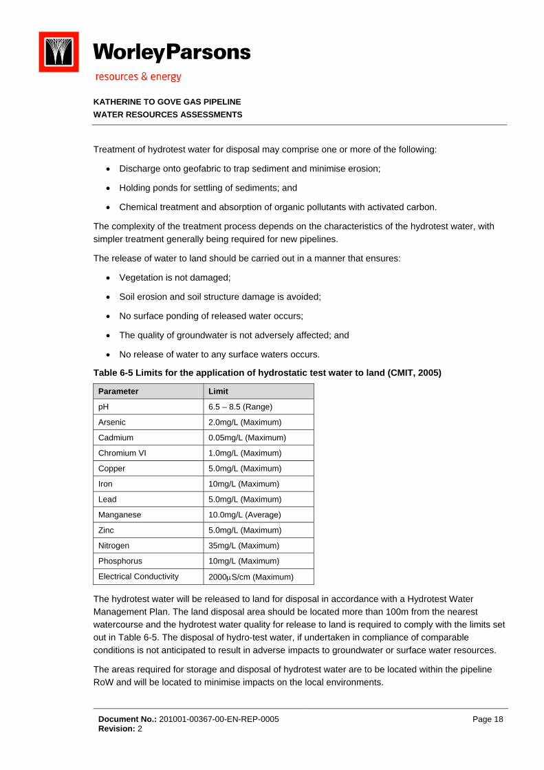
Table 6-5 Limits for the application of hydrostatic test water to land (CMIT, 2005)
Parameter Limit
pH 6.5 – 8.5 (Range)
Arsenic 2.0mg/L (Maximum)
Cadmium 0.05mg/L (Maximum)
Chromium VI 1.0mg/L (Maximum)
Copper 5.0mg/L (Maximum)
Iron 10mg/L (Maximum)
Lead 5.0mg/L (Maximum)
Manganese 10.0mg/L (Average)
Zinc 5.0mg/L (Maximum)
Nitrogen 35mg/L (Maximum)
Phosphorus 10mg/L (Maximum)
Electrical Conductivity 2000S/cm (Maximum)
The hydrotest water will be released to land for disposal in accordance with a Hydrotest Water Management Plan. The land disposal area should be located more than 100m from the nearest watercourse and the hydrotest water quality for release to land is required to comply with the limits set out in Table 6-5. The disposal of hydro-test water, if undertaken in compliance of comparable conditions is not anticipated to result in adverse impacts to groundwater or surface water resources.
The areas required for storage and disposal of hydrotest water are to be located within the pipeline RoW and will be located to minimise impacts on the local environments.
K
W
6
Tssi
waro
Tind
V
6
WrepaTw
Tsoalothaest
Testhreh‘p
HCSath
KATHERINE T
WATER RESO
Document NoRevision: 2
Wa6.4
The sanitary wite and dispoite sewage a
wastewater mppropriate seoad transpor
Trade waste in accordanceisposal.
Vehicle wash
Im6.5
Water for conesources whrogrammed dequate wat
The anticipatewater for cons
The estimatedources for exverage depth
ocations on ehe project eas well as thextractions artreamflows b
The estimatedquivalent to urface waterhat not less tequirementsave no signif
permanent’ w
However, it isCreek represeSeptember. T
dditional invehe western e
TO GOVE GAS
OURCES ASS
o.: 201001-00
astewate
wastewater sosed of in acand sullage tr
may be recycetbacks fromrted and disp
including oil e with ‘Guide
-down water
pacts on
nstruction purere practicabfor the ‘dry’ ster supply maed demands struction pur
d flows listedxtraction of whs of runoff leach watercoach month due correspondre ‘one off’ ocbeyond the 2
d total volumless than 1%rcourses durthan 80% of . Therefore, ficant negati
watercourses
s noted that tent 25-50% o
The planned estigation is
end of the pip
S PIPELINE
ESSMENTS
0367-00-EN-R
r manag
stream will cocordance witreatment sys
led for laundm constructioposed of at se
and grease felines for On-
r will be direc
n Hydrolo
rposes and pble and sustaseason from ay not be avafor potable wposes and th
d in Table 6-6water during isted in Tabl
ourse. The dauring the coning monthly ccurrences th
2014 ‘dry’ sea
me of water re% of the estiming the constthe natural flit is considerve impacts o
s.
he projectedof the total floextractions mrecommend
peline from a
REP-0005
ement
omprise bothth statutory rstems and th
dry and toilet n camps andewage plants
from worksh-site Pre-trea
cted to holdin
ogic Reg
potable suppainable. It is July to Noveailable from water for thehe potential s
6 for each ofthe construcle 6-2 and thata presente
nstruction pevolume dischat last for leason.
equired for thmated total fltruction periolow in surfacred that the pon the hydrol
d demands toow in the strmay have siged for those
alternative str
h grey water regulations, ihe disposal a
use. Effluend watercourss such as at
ops will be tratment’ prior
ng tanks for r
gime of W
ply to the camnoted that cember 2014.some stream temporary csurface wate
f the surface ction period he catchment
ed in Table 6riod, based oharged in theess than six
he project is ow past the od. NT goverce watercoursproposed extlogic regimes
o be sourcedeams for ‘avgnificant impastreams. It m
reams or from
and seweragncluding ‘Co
and reuse of
t disposal arses. The settKatherine, D
reated in dedto transport
removal of w
Watercou
mps will be exonstruction o Therefore, i
ms for some oconstruction er sources ar
watercoursehave been det areas above-6 lists projecon the currene watercoursmonths and
approximateproposed exrnment policyses is availatraction froms and riverine
from the Kinerage’ condiacts on the rmay be necem groundwat
ge which wilode of Practisewage efflu
reas will be lotled solids or Darwin and N
dicated treatmoff-site and
weed seed pr
urses
xtracted fromof the pipelinit is possible of the constrcamps and n
re presented
es considereerived from te the pipelincted volument constructiose. It is notedare unlikely
ely 207ML, wxtraction locay generally able for enviro
m surface wate ecology fo
ng River anditions during river ecosystessary to obtater.
Page
l be treated oce for small o
uent’. Treatedocated with sludge will b
Nhulunbuy.
ment facilitieapproved
rior to release
m surface wane is
that an ruction periodnon-potable in Table 6-6
d as potentiathe monthly e crossing s required byon programmd that the to affect
which is ations on the aims to ensuonmental flowtercourses wr most of the
d Beswick August and ems and ain water for
19
on on-
d
be
s
e.
ater
d.
6.
al
y me,
re w
will e
r

KATHERINE TO GOVE GAS PIPELINE
WATER RESOURCES ASSESSMENTS
Document No.: 201001-00367-00-EN-REP-0005 Page 20 Revision: 2
It is also noted that the planned extraction from the Cato River in October 2014 exceeds 13% of the estimated discharge. It may be necessary to obtain some of the water from Boggy Creek in order to minimize impacts on hydrologic regime and river ecosystems.
It will be necessary to develop appropriate management plans for the extraction of water from surface water in order to minimize potential impacts on hydrologic regime and river ecosystems. The management plans may require the installation of temporary stream gauges to facilitate monitoring of flows in the streams.
Additional investigation of ‘dry’ season flow behavior of surface water resources and baseflow from groundwater is required to be undertaken in order to develop appropriate operating rules for sustainable extraction of water from surface water and groundwater resources. The adaptive management of water extractions is also discussed in 6.9.

KATHERINE TO GOVE GAS PIPELINE
WATER RESOURCES ASSESSMENTS
Document No.: 201001-00367-00-EN-REP-0005 Page 21 Revision: 2
Table 6-6 Anticipated Water Demand and Surface Water Sources (ML)
Month Stream Total Demand Estimated Flow
Jul-14 King River
7.51 70 Aug-14 8.08 33 May-14
Beswick Ck
2 177 Jun-14 2 66 Jul-14 2 33 Aug-14 8.11 16 Sep-14 2 7 Jun-14
Waterhouse River 0.08
1250 Jul-14 625 Aug-14 17.12 295 Aug-14
Latram River 7.32 730
Sep-14 630 Jul-14
Giddy River 0.08
700 Aug-14 450 Sep-14 5.01 300 Jun-14
Mainoru River
2 1750 Jul-14
4.08 950
Aug-14 580 Sep-14 20.59 500 Oct-14 2 480 Jul-14
Wilton River
2.5 2300 Aug-14 2.58 1400 Sep-14 2.5 1220 Oct-14 24.74 1170 May-14
Cato River
2 5680 Jun-14 2 1130 Jul-14
4.08 725
Aug-14 470 Sep-14 2 310 Oct-14 34.20 250 Jul-14
Boggy Ck
2.5 1190 Aug-14
5.08 770
Sep-14 510 Oct-14 2.5 405 Sep-14
Goyder River 0.11 1470
Oct-14 13.13 1580 Nov-14 13.13 1860 Totals 206.8 32083
K
W
6
6
T2u
Tse
Dp
6
6
TDb
Tthe
H
It b
6
If o
KATHERINE T
WATER RESO
Document NoRevision: 2
Co6.6
6.6.1 Co
The construct014 at Govendertaken pr
Thus, the pipeeason when
Detailed descrovided in th
Cro6.7
6.7.1 Ho
The crossingsDrilling (HDD)
elow particu
The risks asshose of a tradliminated:
Mainten
Exposu
Damag
However, incr
Pipe is
Corrosi
Subsid
Visual l
t is understooeen underta
6.7.2 Alt
f the detailedther conditio
Reloca
TO GOVE GAS
OURCES ASS
o.: 201001-00
nstructi
nstructio
tion programe and be comrogressively,
e laying activthe minor st
criptions of thhe Project De
ossing C
rizontal D
s at the ident) constructiolar geograph
ociated with ditional trenc
nance of dist
ure of pipe du
ge of pipe du
reased risks
inaccessible
ion due to un
ence at entry
leak detectio
od that limiteken.
ernatives
d geotechnicaons that indic
tion of the cr
S PIPELINE
ESSMENTS
0367-00-EN-R
on Impac
on Progra
m proposes thmpleted in Oc, within 3-4 w
vities, includitreams are e
he proposed escription cha
Construc
Direction
tified ‘permann. HDD mini
hical features
an HDD instched crossing
turbed banks
uring peak flo
e to anchors
associated w
e for repairs d
ndetected da
y and exit po
on is not poss
ed geotechnic
s to HDD
al investigatiocate HDD is n
rossing and d
REP-0005
cts – Str
am
hat trench exctober 2014, weeks of tren
ing watercouexpected to h
constructionapter of the E
tion Tec
al Drill in
nent’ rivers wmises the riss.
tallation during. In particul
s or stream b
ow events; a
s or other thir
with HDD cro
due to depth
amage to pip
oints; and
sible.
cal investiga
on of the HDnot practicab
deviation of t
ream Cro
xcavation begwith pipe lay
nch excavatio
urse crossinghave minimal
n methods to EIS.
hniques
g
will be constrsk of environ
ng operationar, the risk o
bed;
and
rd party activ
ossings durin
h of cover;
e coating;
tions of the p
DD sites reveble, the follow
the pipeline r
ossings
gin in June 2ying, backfillion.
gs, are to be flow or to be
be used for
ructed using mental harm
s are generaof the followin
vities.
ng operation
proposed HD
eals the existewing options
route; or
2014 at Katheing and resto
undertaken e dry.
stream cros
Horizontal Dm by sending
ally considerng problems
include:
DD crossing
tence of a rocmay be asse
Page
erine and Juoration being
during the ‘d
sings are
Directional the pipeline
able less thais minimized
sites have
ck shelf or essed:
22
ly g
dry’
an d or

KATHERINE TO GOVE GAS PIPELINE
WATER RESOURCES ASSESSMENTS
Document No.: 201001-00367-00-EN-REP-0005 Page 23 Revision: 2
Construction of an open trenched crossing.
The relocation of the HDD crossing and deviation of the adjoining pipeline sections may be feasible where the unsuitable geotechnical conditions are localised and a suitable alternative crossing site can be located within a short distance. This option may require negotiation of an amended RoW and approvals from the administering authorities.
It is considered that construction of an open trenched crossing is the most appropriate option where a minor deviation of the pipeline is not possible. The construction of trenched crossings is described below.
6.7.3 Trenched Crossings
Trenched crossings will be constructed at ephemeral stream crossing sites and where site geotechnical investigations indicate that HDD crossing of a ‘permanent’ watercourse is not considered practicable.
Trenching across waterways involves in-stream excavation and pipe laying conducted within a temporarily dewatered section of the waterway. Protection of the works from stream flows is achieved by installing temporary dams upstream and downstream with a bypass channel or pump.
Strategically located sumps allow dewatering in the ‘dry’ area where the water table is exposed. Water resulting from dewatering may be directed to on-site sedimentation ponds or carted to alternative water storage ponds to separate sediment before discharge back into the stream when deemed appropriate, or may be used for dust suppression or other construction purposes.
In the event that HDD cannot be carried out at watercourse crossings with significant flow, flow diversion will be required. This is a modification to the standard open cut method. The technique involves construction of temporary dams, upstream and downstream of the crossing, and diversion of water around the crossing point. This creates a dry construction area between the dams.
The two possible flow diversion techniques are:
Bypass flume, where flow is diverted through flume pipes to prevent siltation, which would arise during trenching, lowering in and backfilling. This technique is less suitable for watercourses with significant flows, broad channels, low gradients or permeable substrates; and
Dam and pump, where coffer dams or head walls are constructed above and below the trenched area and the work area is pumped dry. This is appropriate for low gradient streams with discharges of less than about 1m3/s during construction.
Either technique could be used during periods of very low water flow if practicable, with consideration of short-term weather forecasting to avoid any potential for flooding during the open trench phase of the crossing.
Rehabilitation will be undertaken in accordance with the Code of Environmental Practice (APIA, 2009) and re-contoured to match the surrounding land as soon as practicable after pipe laying and backfilling and bank erosion controls will be constructed or installed, where necessary. An effective
K
W
sein
6
Acopd
It opbthb
Tatrth
Tim
6
Timst
Tcthcin
Tcotr
Td
Tsto
KATHERINE T
WATER RESO
Document NoRevision: 2
ediment andn runoff durin
6.7.4 Pot
As stated aboonditions. Lolant and ancuring the ‘dry
t is anticipatef the plannederiod possibackfilling of t
he very unlike open for u
The excavate bund for tem
rench crossinhe open sect
The short durmpact on stre
Sto6.8
The stormwatmplemented tormwater ru
The managemhanges in thhe watercourhanges in ch
ncreased flow
The managemontaminatedreatment of b
The potentiallisposal or is
The minimisatormwater. Tf the activitie
TO GOVE GAS
OURCES ASS
o.: 201001-00
d erosion conng the constr
tential Im
ove, HDD avoocalised eroscillary works dy’ season, it
ed that the md pipe layingle. Typical pthe trench. Lely event of p to six days
ed material frmporary storang may be untion of the cro
rations requireamflow beh
ormwate
ter managemin order to m
unoff dischar
ment of the qe locations arses. The sohannel alignmws or other c
ment of stormd areas withinboth streams
ly contaminato be treated
tion of sedimThe managemes undertake
S PIPELINE
ESSMENTS
0367-00-EN-R
ntrol programruction period
mpacts on
oids impactssion of riverbduring flood is considere
minor streamsg period. Trenractice wouldarger crossinhaving to bla
s.
om the trencage of very lndertaken in ossing.
red for any dhaviour.
r Manage
ment strategyminimize the ged to water
quantity of stoand magnitudils along the ment and crochanges in flo
mwater qualitn the camps s.
ated stormwad on-site prio
ments in runoment of nutrin and polluta
REP-0005
m will be impld and long-te
n Stream
s on streamflbank areas mevents. As p
ed that stream
s will be dry onches in the d be a maximngs would reast the trench
ch will be plaow streamflo two stages w
diversion or te
ement
y comprises wimpact of thercourses.
ormwater rundes of flows pipeline rou
oss-section mow behaviou
ty is focusseand facilities
ater is to be cor to discharg
off dischargeents is not cants normally
emented to merm operatio
Hydraulic
ow behavioumay be inducepipeline consmflow at the
or will have mwaterway cr
mum of two dequire the treh due to the
ced on the uow. Where thwith flow div
emporary sto
works to be e pipeline pro
noff dischargin order to pte are susce
may result frour.
d on separats from ‘clean
captured andge.
d from the sionsidered toy contained
mitigate poten.
cs
ur, under nored by flow co
struction is plHDD crossin
minimal grourossings will days from staench to be oppresence of
upstream sidehis is not conerted via cha
orage of stre
carried out aoject on the q
ged is focuserevent erosioptible to eros
om concentra
tion of runoff’ stormwater
d transported
te is the primo be a significin stormwate
ential impacts
rmal dry weaonditions arolanned to be ngs is unlikel
undwater fed be open for art of trenchipen for up to hard rock, th
e of the crosnsidered pracannels const
amflow will m
and measurequantity and
ed on minimizon and sedimsion and signation of over
f from potentr runoff and a
d off-site for t
mary focus focant issue duer runoff.
Page
s from turbid
ther flow ound the HDD
undertaken y to be altere
flow for mosthe minimumng until four days. In
he trench ma
ssing to creatcticable, the tructed aroun
minimise the
es to be quality of
zation of mentation alonificant land flows,
tially appropriate
treatment an
or ‘clean’ ue to the natu
24
dity
D
ed.
st m
n ay
te
nd
ong
d
ure
K
W
Rflodcoa
Strre
Sinin
Rcoabtoa
6
Tp
T
A
W
W
KATHERINE T
WATER RESO
Document NoRevision: 2
Runoff from eows to be coevices, wheroncentrationreas and is t
Surface runofreatment devetention basi
Stormwater runcrease the lncluding ene
Refuelling andoncentrated ny contaminunded areas
o be directedpproved loca
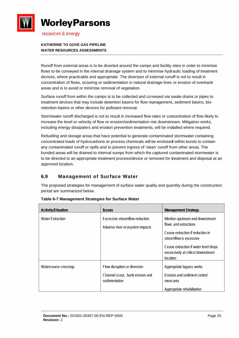
Ma6.9
The proposederiod are sum
Table 6-7 Ma
Activity/Situatio
Water Extraction
Watercourse cro
TO GOVE GAS
OURCES ASS
o.: 201001-00
external areaonveyed in thre practicable
n of flows, scoto avoid or m
ff from withinvices that mains or other d
unoff discharevel or velocrgy dissipate
d storage areloads of hydated runoff o
s will be draind to an approation.
anageme
d strategies fmmarized be
anagement S
on
n
ossings
S PIPELINE
ESSMENTS
0367-00-EN-R
s is to be divhe internal dre and appropouring or sed
minimise remo
n the camps iay include dedevices for p
rged is not tocity of flow orers and erosi
eas that havedrocarbons oor spills and tned to internopriate treatm
nt of Sur
for managemelow.
Strategies fo
Issu
Exc
Adv
Flow
Chased
REP-0005
verted arounrainage systepriate. The ddimentation oval of vege
is to be colleetention basipollutant remo
o result in incr erosion/sedion preventio
e potential toor process chto prevent inal sumps fro
ment process
rface Wa
ment of surfac
or Surface W
ues
cessive streamf
verse river ecos
w disruption or
annel scour, baimentation
d the campsem and to mdiversion of ein natural dratation.
ected and conns for flow moval.
creased flow dimentation ron treatments
o generate cohemicals will ngress of ‘cleom which thes/device or re
ater
ce water qua
Water
flow reduction
system impacts
diversion
ank erosion and
and facility sinimise hydra
external runoainage lines
nveyed via smanagement,
rates or conrisk downstres, will be inst
ontaminatedbe enclosedan’ runoff fro captured co
emoved for tr
ality and qua
Mana
Monitoflows
Ceasestream
Ceaseexceslocatio
d
Appro
Erosiomeasu
Appro
sites in ordeaulic loading
off is not to reor erosion of
swale drains , sediment ba
ncentration oeam. Mitigatitalled where
d stormwater d within bundom other areontaminated reatment and
ntity during t
agement Strate
or upstream an and extractions
e extraction if remflow is excess
e extraction if wssively at criticaon
opriate bypass w
on and sedimenures
opriate rehabilita
Page
r to minimiseg of treatmenesult in f overbank
or pipes to asins, bio-
f flow likely tion works, required.
containing ds to contain as. The stormwater id disposal at
the construct
egy
nd downstream s
eduction in sive
water level dropal downstream
works
nt control
ation
25
e nt
o
is t an
tion
ps

K
W
P
H
San
W
C
Tcow
6
T
KATHERINE T
WATER RESO
Document NoRevision: 2
ipeline construc
ydrotesting
tormwater discnd temporary fa
Wastewater disp
Contaminated w
The following onstruction a
watercourses
Stormw
Hydrote
Wastew
Water E
Waterc
Pro6.10
The following
TO GOVE GAS
OURCES ASS
o.: 201001-00
ction
harged from caacilities
posal
wastewater
managemenand will be im:
water Manag
est Water Ma
water Dispos
Extraction M
course Cross
oposed M
activities are
S PIPELINE
ESSMENTS
0367-00-EN-R
Erosstoc
Eros
Wat
amps Con
Eros
Wat
Hyd
nt plans will bmplemented
ement Plan (
anagement P
sal Managem
anagement
sings Manage
Mitigatio
e to be comp
REP-0005
sion of exposedckpiles
sion of backfille
ter quality in rec
ncentrated flows
sion and sedim
ter quality in rec
drocarbons
be prepared during the co
(including Er
Plan;
ment Plan;
Plan; and
ement Plan.
on Measu
pleted during
d areas and
ed trench
ceiving waterco
s
mentation
ceiving waterco
prior to the construction p
rosion and S
ures
g the design
Erosiomeasudrains
Rock
Comp
ourses Qualit
Maxim
Land rates
Approand o
Erosiomeasu
ourses Approareas
Collec
commencemperiod to min
ediment Con
phase:
on and sedimenures – silt fences, sediment bas
check dams in
paction of backf
ty criteria
mize re-use
disposal only –
opriate surface outlets
on and sedimenures – sedimen
opriate treatmens
ction and appro
ment of the pnimise impac
ntrol Plan);
Page
nt control es, diversion sins
trenches
fill
– area, applicati
drainage works
nt control nt basins
nt and disposal
opriate treatmen
ipeline ts on surface
26
on
s
nt
e
K
W
T
T
6
RopNcaa
It
KATHERINE T
WATER RESO
Document NoRevision: 2
Concepcross-sareas;
Prepara
Prepara
The following
Implem
Mainten
Maintenareas f
All fuelsminimis
Construamend
Implem
Implem
The work to b
Implem
Implem
Co6.11
Rainfall and rccurring oveeriod betwee
November anatchment sand June refle
t is considere
It is probetwee
The crothat avo
Trenchgeotech
TO GOVE GAS
OURCES ASS
o.: 201001-00
ptual design section and p
ation of conc
ation of Stor
actions are
mentation, rev
nance and re
nance and cfrom where th
s and chemicse the potent
uction of storments requir
mentation of m
mentation of s
be undertake
mentation, rev
mentation of a
nclusion
esultant runoer the six monen Decembend the rise in turation and ects the base
ed that the pr
oposed to coen June and
ossings at thoids impacts
ed crossingshnical invest
S PIPELINE
ESSMENTS
0367-00-EN-R
of sedimentaprofile and in
ceptual Erosi
mwater Man
to be undert
view and upd
epair of ESC
leaning of vehe resultant
cals to be stotial for conta
rmwater manred due to ch
management
surface wate
n during the
view and upd
a litter and so
ns
off in the regnth period fro
er and May. Tstreamflow iresultant su
eflow from gr
roject will no
nstruct the pNovember w
e identified ‘ps on streamflo
s will be constigations indic
REP-0005
ation/detentiternal site dr
ion and Sedi
nagement Pla
taken during
dating, if nec
CP devices;
ehicles and acontaminant
ored and hanmination of s
nagement wohanges in fac
t measures s
er extraction
operations p
dating, if nec
olids manage
ional is highom NovembeThe lag betwin Decemberrface runoff. roundwater a
t impact surf
pipeline and wwhen the maj
permanent’ row behaviou
structed at ecate that HD
on basins forainage, inclu
iment Contro
an (SWMP).
the construc
cessary, of th
any other equts cannot be
ndled in accostormwater r
orks in accorcility design o
specified in t
managemen
phase compr
cessary, of th
ement plan t
ly seasonal, er to April an
ween the onser is due to thSimilarly, th
as the soils d
face water re
watercourse jority of strea
rivers will be ur, under nor
phemeral strDD crossing o
r flow attenuuding bundin
ol Plan (ESC
ction phase:
he ESCP;
uipment or preleased to
ordance withunoff from th
rdance with Sor other facto
he SWMP; a
t measures.
rises:
he SWMP; an
o minimise g
with approxind streamflowet of the ‘wete build-up ofe recession drain.
esources sign
crossings duams will not b
constructedmal dry weat
ream crossinof a ‘permane
uation, diversng of contam
P); and
plant to be caany waterco
h AS 1940 anhe site;
SWMP, subjors;
and
nd
gross solids l
imately 90% w generally ot’ season raif soil moisturof streamflow
nificantly, giv
uring the ‘drybe flowing.
d using HDD ther flow con
ng sites and went’ waterco
Page
sion drain ination risk
arried out in urse;
nd AS 3780 t
ect to
loads in runo
of the rainfaoccurring in tnfall in re prior to w through M
ven that:
y’ season
constructionnditions.
where site urse is not
27
to
off.
all the
ay
n
KATHERINE TO GOVE GAS PIPELINE
WATER RESOURCES ASSESSMENTS
Document No.: 201001-00367-00-EN-REP-0005 Page 28 Revision: 2
considered practicable. The short durations required for any diversion or temporary storage of streamflow for trenched crossings will minimise the impact on streamflow behaviour.
An adaptive management strategy will be developed following additional investigation of streamflow and water quality characteristics of the surface watercourses during the ‘dry’ season and implemented to minimise impacts on river ecosystems resulting from extraction of water for construction of the pipeline.
K
W
7
TKsep
7
TGcoloa
Tinari
TTT
1
KATHERINE T
WATER RESO
Document NoRevision: 2
7 HY
The following KGGP route; upplement thxisting datasotential risks
Re7.1
The Northern Groundwater onsidered to
ow intensity oreas are rec
The Water Acn an effort to reas where tvers) or the
The proposedThese GMUs These are de
National Water
TO GOVE GAS
OURCES ASS
o.: 201001-00
YDROGEO
hydrogeologwith particulhe water reqset relating tos associated
gional H
Territory obManagemen
o be under reof land use. Hognised as b
ct enables thprovide incr
there is a nepreservation
d easement fare largely cscribed in m
Planning Repo
S PIPELINE
ESSMENTS
0367-00-EN-R
OLOGY A
gy assessmear emphasisuirements foo the availabwith its use.
Hydrogeo
tains about 1nt Units (GMelatively little However, grobeing under p
e declarationeased watered to avoid sn of wetlands
for the KGGPcontained in ore detail in
rt Card/ Norther
REP-0005
ASSESSM
ent describess on establishor the projectbility and/or o
ology
128 gigalitresUs). The Nopressure duoundwater apressure from
n of Water Cr managemestress on gros (e.g. GDEs
P (Figure 7-1the McArthuSection 7.2.
rn Territory
MENT
s the regionahing if groundt. Additionallyoccurrence of
s (GL) of grorthern Territoe to a compand surface wm resource d
ontrol Districnt and protec
oundwater res).
1) traverses aur River and
al hydrogeolodwater is a sy, this Sectiof groundwate
oundwater peory’s water rearatively sma
water resourcdevelopment
cts (WCD) wiction. This is
eserves, base
a total of six Daly River g
ogical settingsustainable reon also examer, it’s quality
er annum froesources arealler populatces in a numt (NWC, 201
ithin the Nors usually carreflow to surfa
(6) GMUs (Froundwater
Page
g along the esource to
mines the y and the
m 55 e generally ion base and
mber of local 11).
thern Territoried out in ace waters (
Figure 7-2). provinces.
29
d
ry
i.e.
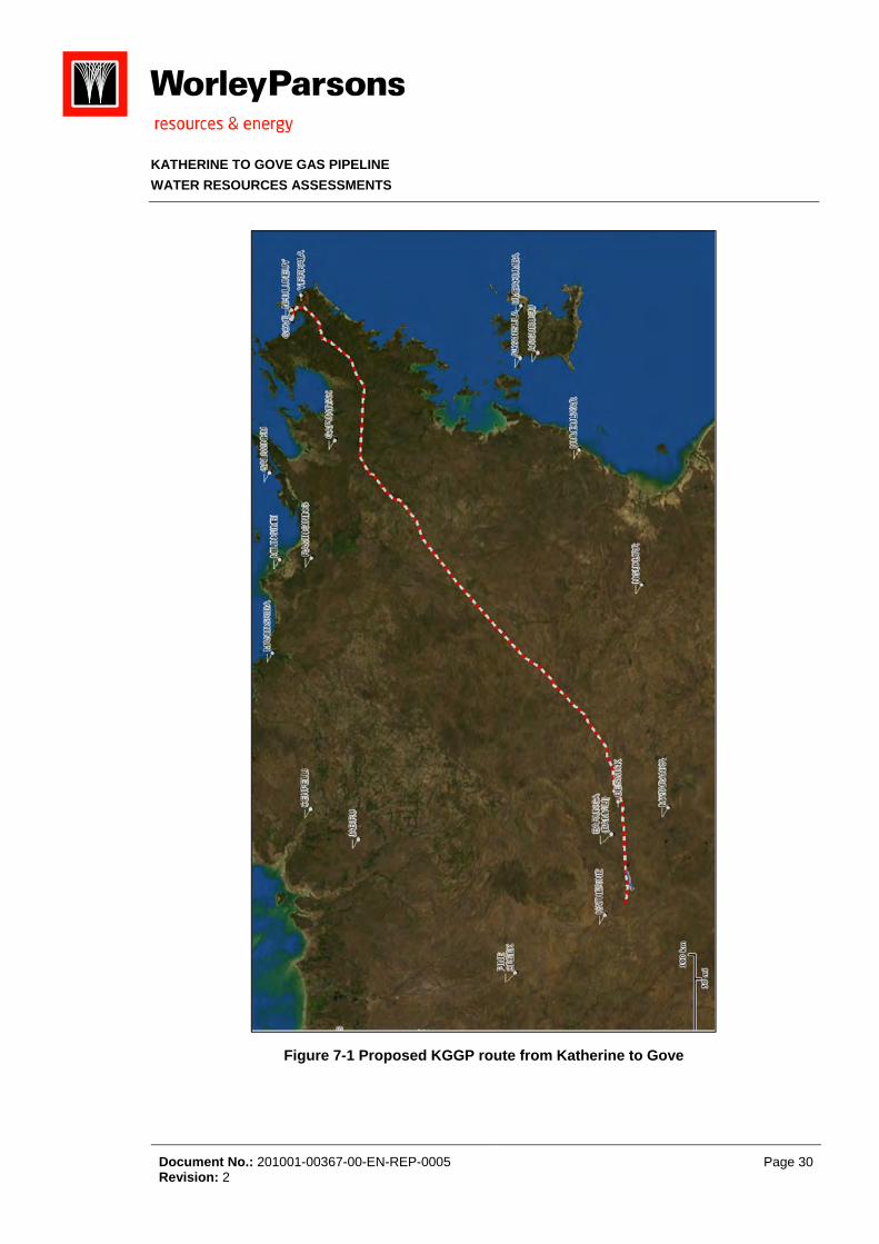
KATHERINE TO GOVE GAS PIPELINE
WATER RESOURCES ASSESSMENTS
Document No.: 201001-00367-00-EN-REP-0005 Page 30 Revision: 2
Figure 7-1 Proposed KGGP route from Katherine to Gove

KATHERINE TO GOVE GAS PIPELINE
WATER RESOURCES ASSESSMENTS
Document No.: 201001-00367-00-EN-REP-0005 Page 31 Revision: 2
Figure 7-2 Groundwater Management Units (GMUs) Pipeline Easement (Eco Logical, 2013)
K
W
7
TGDa
T
Ta
7
TTdbghdindu
Aswcas
LETra
KATHERINE T
WATER RESO
Document NoRevision: 2
Gro7.2
The Northern Groundwater Districts (WCD
nd protection
The proposed
Daly Ri
Daly Ri
Protero
Protero
Protero
McArth
These GMUs re described
7.2.1 Da
The first apprThree aquifer
ipping carboores can proenerally gooydraulically cischarge gro
nto the aquifeependent upnconfined an
A borefield 3kupply of 4,03
water to increalcium (Ca2+
upports a sm
imestone intEvaporite depTotal Dissolveadium (Ra) c
TO GOVE GAS
OURCES ASS
o.: 201001-00
oundwat
Territory obManagemenD) within then.
d KGGP rout
iver Basin –
iver Basin –
ozoic Sedime
ozoic Rocks
ozoic Sedime
hur Basin inc
are largely cd below. The
ly River B
oximately 50rs are presenonate rocks. Toduce water od and suitabconnected tooundwater wher. Distributepon whether nd open to d
km east of th39 million litreease pH, mak+) and magnemall horticultu
ter-fingers wiposits in the sed Solids (TDcontents have
S PIPELINE
ESSMENTS
0367-00-EN-R
ter Mana
tains about 1nt Units (GMe Northern Te
te traverses t
Tindall Lime
Jinduckin Fo
entary Rock (
low yielding
entary (Adela
luding Gove
contained in ese include:
Basin –Ti
0-kilometres nt, all formatiThe major aqup to 60 Litre
ble for most po the Katherihen river leve
ed recharge athe aquifer isirect recharg
e town of Kaes is from thking it less coesium (Mg2+)ural and crop
ith the overlyshales locallDS) reach a e also been
REP-0005
gement
128 gigalitresUs). The Waerritory which
the following
estone.
ormation.
(North East
(Bulman).
aide River).
Water Contr
the McArthu
indall Lim
of the propoons in the Loquifer is the Tes/sec (L/s) purposes. Thne River. Spels are low; also occurs, s confined byge
atherine suppese groundworrosive to m)) limits the ppping industr
ying Jinduckiy impart highmaximum ofreported.
Units (G
s (GL) of groater Act enabh provides an
g six (6) GMU
Northern Ter
rol District (W
ur River and
mestone
sed KGGP rower PalaeoTindall Limesand average
he aquifer is prings in the rhowever, duaveraging apy the overlay
plements thewater bores. metal. High hproportion of ry.
n Formation h sulfate (SOf 4000 milligr
MUs)
oundwater pebles the declan increased l
Us (refer to F
rritory).
WCD).
Daly River g
oute is withinzoic Daly Bastone, the ba
e 80 metres dfractured andriver bed andring flood evpproximatelyying cretaceo
e river water. Groundwateardness (a mgroundwater
to form lessO4
2-) concentrrams per litre
er annum froaration of Wlevel of wate
Figure 7-2).
roundwater
n the Daly Rasin; a sequeasal formatiodeep. Water d cavernousd bank at Kavents river way 40 to 140mous sedimen
Up to 40% oer is blended measure of thr used. The
s extensive arations to groe (mg.L-1) an
Page
m 55 ater Control
er manageme
provinces, an
iver Basin. ence of gentlyon. Individualquality is and is therine ater flows ba
mm/year ts or
of the annuawith the rive
he amount ofaquifer also
quifers. oundwater. d elevated
32
ent
nd
y l
ack
al er f
KATHERINE TO GOVE GAS PIPELINE
WATER RESOURCES ASSESSMENTS
Document No.: 201001-00367-00-EN-REP-0005 Page 33 Revision: 2
The uppermost formation in the basin, the Oolloo Limestone forms a major aquifer similar in properties to the Tindall Limestone. The depth to groundwater level varies during the year, in response to rainfall recharge, from 3 – 25 metres.
7.2.2 Daly River Basin – Jinduckin Formation
The Jinduckin Formation is located within the Daly River Basin. This comprises gently dipping Palaeozoic Jinduckin Formation of the Daly River Basin sequence. The aquifers are present in fractured and karstic limestone interbeds within a section consisting mainly of siltstone. Bores in the limestone are capable of producing moderate yields. Water quality is generally moderate and may be locally brackish due to the presence of interbedded evaporite deposits. Such groundwaters are high in sulfate (SO4
2-), calcium (Ca2+), sodium (Na+) and chloride (Cl-). Recharge comprises both distributed recharge and infiltration from rivers. The Daly and Katherine Rivers cross the area and these receive minor discharge from the aquifers. The underlying Tindall Limestone, which comprises UA NT242, dips beneath the Jinduckin Formation and forms the most productive aquifer.
7.2.3 Proterozoic Sedimentary GMUs (North East NT, Bulman & Adelaide River)
With reference to Figure 7-2, extending north-east from Beswick there are three (3) GMUs, referred to as Unicorporated Areas (UA), of which the KGGP traverses. These are Proterozoic-aged sedimentary units of the 1) North East Northern Territory, 2) Bulman and 3) Adelaide River GMUs; with sustainable groundwater yields of 500,000 ML, 22,000ML and 99,800ML respectively. Little is known of these GMUs; however, these Proterozoic units are generally gently folded with shale and siltstone as the dominant rock type. Aquifers associated with these GMUs are fractured systems, predominantly at depths of less than 100m.
7.2.4 McArthur Basin
The majority of the length of the KGGP passes through the McArthur River Basin which has five GMU’s and includes the Gove WCD. These include:
Gently folded Proterozoic sandstone and shale are the dominant rocks but dolomite, siltstone and greywacke also occur. Aquifers are the fractured rock type, mostly developed shallower than 100 metres. Bore yields are mostly less than 2 L/sec but higher yields occur near major fracture zones. Several mines use groundwater for processing and undertake varying levels of dewatering. Recharge is of the distributed type, probably less than 5mm/year. Discharge occurs via springs and into riverbeds.
Proterozoic dolomite comprising the Dook Creek Formation; a unit of the gently folded Proterozoic McArthur Basin. The aquifer associated with this formation is virtually untested but may contain a major groundwater resource. Recharge is of the distributed type, probably within
2 Unincorporated Area (UA) designated NT24
K
W
G
Tpsom6va1
7
Cmlorein
AthS
3 se
KATHERINE T
WATER RESO
Document NoRevision: 2
the ran1000 L/
Low-Yilow perof shaleeither ato the c
CretaceCretaceresourcgood w
Recharoccurs more th
Gove Water C
This is a declaoorly consolouthwest. Th
major user is 0 L/sec eachalues genera0 to 50 mm/y
Wa7.3
Climatic variamuch of the cowest, and weduce/negatenfrastructure
At present thehe KGGP areSections.
The groundwaeason
TO GOVE GAS
OURCES ASS
o.: 201001-00
ge 10 to 50 /sec in the G
elding Protermeability roce and siltstonabsent or spacoast and tid
eous sedimeeous sands. ce, similar to
with TDS valu
rge is of the das baseflow
han 100 L/se
Control Distri
ared Water Cidated, flat lyhe towns of Nthe Gove ba
h. The total sally less thanyear. Discha
ater supp
ations througconstruction wwhen baseflowe the need to(if required)
e following we those show
ater contributi
S PIPELINE
ESSMENTS
0367-00-EN-R
mm/year. DisGoyder River
rozoic rocks cks in the gene are the doarsely develoal rivers. Rec
entary rocks. The aquifer that in the G
ues generally
distributed tyw into riverbedec.
ict (WCD)
Control Distrying CretaceoNhulunbuy aauxite mine. Psupply from tn 100 mg.L-1.arge occurs a
plies for
hout the yeawill take placw3 is at its mo undertake .
water requiremwn in Table 6
on to a stream
REP-0005
scharge occis supplied f
(near the towently folded Pominant rockoped low-yiecharge is like
This formatiis virtually u
Gove Water Cy less than 1
ype, probablyds. Several o
ict, located inous sands innd Yirrkala oProduction bthe borefield . Recharge isas baseflow i
propose
ar will influencce during the
minimum. Thislarge-scale d
ments (i.e. h6-6. These ar
m; baseflow of
urs as baseffrom dischar
wn of BulmaProterozoic Mks but doleritelding fractureely to be very
ion comprisentested but mControl Distr00 mg.L-1.
y within the rof the areas
n northeast An an outlier oobtain their wbores are typis 1697 Ml/ys of the distrinto riverbed
ed KGGP
ce the KGGPe dry season s approach idewatering fo
ydrotesting, re discussed
ften maintains
flow into riverge from the a
n). This formMcArthur Base and graniteed rocks. Say low.
es poorly conmay contain ict to the nor
range 10 to 5streams mai
Arnhem Landf the main bo
water supplieically 80 met
year. Water qibuted type, s.
constru
P constructiowhen grounds favoured aor the installa
HDD, dust s in more det
sources wate
rbeds. A dry aquifer.
mation comprsin. Alternatine also occur.
aline waters o
nsolidated, flaa major grou
rtheast. Wate
50 mm/year. intain dry sea
d. The aquifeody of the fo
es from the atres deep an
quality is gooprobably wit
uction
on schedule; dwater level
as a means toation of pipe
suppression atail in the follo
er to a stream
Page
season flow
rises variousng sequence. Aquifers areoccur adjace
at lying undwater er quality is
Discharge ason flows o
er consists ofrmation to thquifer but the
nd supply up od with TDS hin the range
however, s are at theiro line
and potable)owing
during dry
34
w of
s es e
ent
of
f he e to
e
r
) for
KATHERINE TO GOVE GAS PIPELINE
WATER RESOURCES ASSESSMENTS
Document No.: 201001-00367-00-EN-REP-0005 Page 35 Revision: 2
7.3.1 Water requirements for KGGP pipeline infrastructure: Potential source of groundwater
Where practicable and sustainable it is understood that the main supply of water for hydrotesting of the pipeline, HDD and dust suppression is to source from surface water courses (e.g. King River, Goyder River etc) as identified and discussed in Sections 6.3 to 6.5. However, as discussed in Section 6.11, until such time as an adaptive management strategy has been developed to better our understanding on the sustainability of surface water resources to provide water for the KGGP, other sources of water needs to be considered. Not only is additional water required to supplement construction activities, a good source of potable water is required for the 750 persons working on the KGGP Project.
At present it is unaware if any source for drinking water has been defined. It is understood that the construction of the pipeline will commence concurrently at each end of the proposed pipeline network; where, access to potable water is more common. However, as camp facilities move during construction, especially away from more populated centres, the location, access and quality of water for human consumption becomes somewhat limited. Therefore it is proposed that sources of potable water may come from groundwater bores in the vicinity of the KGGP.
Information on existing groundwater bore infrastructure along the KGGP was collated from the following sources.
Water Resources of North Eastern Arnhem Land (DLPE, 1999);
Water Resources of the Katherine Region and South West Arnhem Land (DLPE, 2001);
Department of Land Resource Management (DLRM) online NR Maps (Northern Territorty); and
Advice from DLRM personnel in the Northern Territory Government and from local experts appointed by Pacific Aluminium’s envirornmental consultant.
These resources were used to assess the occurrence (if any) of ‘existing’ and suitable groundwater bores which could be used as alternative sources of water; principally for human consumption.
With reference to Figures 7.1 to 7.6 (refer Appendix 2) and Table 7-1, a total of thirty (30) groundwater bores were identified. Reviews of these thirty (30) groundwater bores have indicated highly variable bore yields and restricted water quality results for parameters relevant for human health. For example, data abstracted from the 1999 and 2001 DLPE studies, shows that water quality results for these thirty (30) bores are incomplete (refer Table 7-1) and of little value in establishing the true potential for consumption. For example, the Australian Drinking Water Guidelines (NHMRC4 & ARMCANZ5, 1996) provides the necessary criteria in establishing good quality drinking water. These Guidelines provide an authoritative Australian reference on acceptable drinking water quality, covering a wide range of the microbiological, physical, chemical and radiological characteristics.
4 National Health & Medical Research Council 5 Agriculture and Resource Management Council of Australia and New Zealand

KATHERINE TO GOVE GAS PIPELINE
WATER RESOURCES ASSESSMENTS
Document No.: 201001-00367-00-EN-REP-0005 Page 36 Revision: 2
With regards to the present dataset it remains unclear as to wether groundwater can be used as a potable supply; however, it still may be used as a source of water to supplement construction activities. Additional field investigations will be carried out to ascertain the degree to which groundwater from ‘existing’ bores (refer Table 7-1) can be used during construction of the KGGP project.
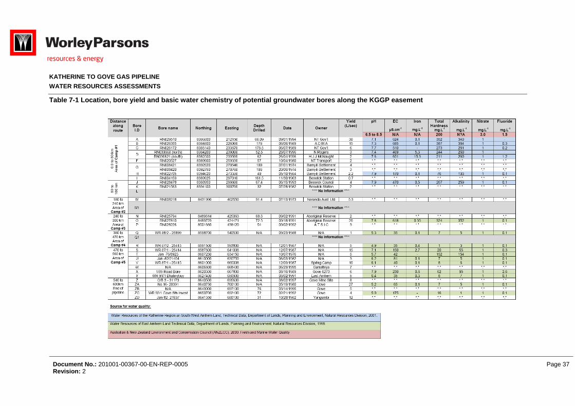
KATHERINE TO GOVE GAS PIPELINE
WATER RESOURCES ASSESSMENTS
Document No.: 201001-00367-00-EN-REP-0005 Page 37 Revision: 2
Table 7-1 Location, bore yield and basic water chemistry of potential groundwater bores along the KGGP easement
K
W
7
DTath
Tre
7
ABcoreKpcoAreaaine
Ramea
6 G(A
KATHERINE T
WATER RESO
Document NoRevision: 2
Po7.4
Data relating Therefore, su
ssess the rishe KGGP.
The following esult of the p
7.4.1 Ac
ApproximatelyBasin. Given ontaminationemainder of t
KP distances otential for thoastal enviro
As groundwatequired for thforementionetmospheric c
nfrastructure ffects to biot
Regulatory poppropriate m
management stablishing assessed indi
EnvironMinisteaquatic
Dear S
GuideliResour
Ahern C
Acid SuResour
Generally occur
ARMCANZ, 199
TO GOVE GAS
OURCES ASS
o.: 201001-00
tential e
to groundwapplemental d
sks to ground
Sections deproposed KG
id Sulfate
y half of the the nature on as a result the KGGP coof ~500km a
he presenceonments6 theter is generahe installatioed sections oconditions, thand release
ta and other
olicy favours management
guidelines foa governing fividually and
nment Protecerial Council. c ecosystems
.E., Moore Nnes. In Queerces and Min
C.R, Ahern Mulfate Soils (Arces Science
r near coastal e
99; Dear et. al., 2
S PIPELINE
ESSMENTS
0367-00-EN-R
nvironm
ater in the aredata will be cdwater quant
escribe the poGGP.
e Soils (A
KGGP crossf the lithologof pipeline corridor there and from ~57of Acid Sulfa
ere is a risk oally shallow inn of pipeline of the pipelinhe oxidation harmful metsensitive rec
avoidance omeasures aor ASS; thereframework. H by an exper
ction and He2011. Nation
s, Canberra,
NG, Dobos Sensland Acidnes, Indooroo
M.R. and PowASS) in Que
e Centre, Ind
nvironments or 2002))
REP-0005
mental ris
ea encompacollected follotity and qual
otential risks
ASS)
ses over mety in these ar
construction a are environ70km to 603fate Soils (ASof intersectingn coastal envinfrastructur
ne there is a products frotals/metalloid
ceptors. This
of areas undere required. efore, the fol
However, eacrienced envir
eritage Councnal guidanceACT;
SK, Watling Kd Sulfate Soilopilly, Queen
well B. 1998eensland (19ooroopilly.
palaeo-coastal
sks from
ssing the KGowing additioity as a resu
s to groundwa
ta-sedimentareas, there isactivities (e.gmentally senkm along theSS). As ASS g and exposvironments, ire. Thereforehigh-risk of Am ASS haveds to the env is described
erlain by ASSThe Northerllowing referech area suspronmental sp
cil and the Ne for the man
K.M. and Ahel Technical Mnsland, Austr
. Guidelines 98). QASSIT
environments (
KGGP d
GGP is, to soonal investigalt of the cons
ater that hav
ary rocks asss a lower riskg. surface spnsitive localese proposed Kgenerally ocing ASS durit is likely tha
e, if ASS is pASS exposure to potential vironment. Thd in more det
S; however, n Territory doences will bepected of, or pecialist.
atural Resounagement of
ern C.R. 2002Manual. Deparalia; and
for SamplingT. Departmen
(<10m Australia
developm
ome degree, ations in an struction and
ve been iden
sociated withk of groundwpills etc). Hows/regions. Fo
KGGP pipelinccurs at shalring pipeline cat dewateringresent alongre. If exposeto damage p
his may havetail in Sectio
if this is not oes not have
e used as a pcontaining A
urce Manageacid sulfate
2. Soil Manaartment of N
g and Analysnt of Natural
an Height Datum
Page
ment
limited. effort to bette
d operation of
tified as a
the McArthuater
wever, over tor example, ane, there is thlow depths iconstructiong will be g the ed to pipeline e irreversiblen 7.4.2.
possible thene specific proxy for ASS, will be
ement soils in inlan
agement atural
sis of LowlanResources,
m (AHD),
38
er f
ur
the at he n .
e
n
nd
nd

K
W
7
AKthhgawsEoreEbstitogad
Teo
Wheaace
7
Wg(rthTpn
AS
KATHERINE T
WATER RESO
Document NoRevision: 2
7.4.2 Pot
As discussed KGGP constrhese systemydraulic conroundwater ind maintains
which this is oupports and
Ecosystems (nly is this a mely on it and
Ecosystems aiophysical asignificantly; bme, and witho recover. Aroundwater bnd Gove WCevelopment.
The area travvaporation af critical impo
Where surfacydrostatic textraction candditional invessessment tharacteristicstablished.
Reg7.5gro
With regards roundwater (refer Sectionhe GMUs repTerritory. The
orous sandsational wate
Although unlikSection 74 of
TO GOVE GAS
OURCES ASS
o.: 201001-00
tential en
in Section 7uction purpos will responnection (i.e. is required. Fs many of theoccurring for maintains su
(GDEs), thermatter of grothe potentia
are fundamessets).The nboth temporahout this acce
At present it isby existing u
CDs. The ma.
versed by theand transpiraortance to th
ce waters (incsting, there in be manageestigations wo be includes for each G
gulatory oundwate
to the legisla(or surface w
n 7.2) presenpresent selece shallow higstone aquiferr quality man
kely, there mthe Water A
S PIPELINE
ESSMENTS
0367-00-EN-R
nvironme
7.3, it is propooses (i.e. dusnd when watebaseflow chaFor exampleese surface weach water
urface water e needs to b
oundwater sul for contamintal for the pature and deally and spatess, the ecos understoodusers in the reain threats to
e KGGP recetion from ripa
he functioning
cluding GDEis also potened appropriatwill be used td in adaptiveDE so that tr
requiremer
ation and mawater), Tablet along the Kcted major aqh yielding aqin the easte
nagement pla
may be a requAct. This will o
REP-0005
ntal rece
osed that wast suppressioer is extractearacteristics), although it water systemsource is larsystems, oth
be a better unupply (i.e. vonation from c
preservation egree of the dtially. GDEs ological dama
d that there isegions of the GDEs involv
eives high anarian vegetag of these ec
Es) are to be ntial for impactely once theto generate ae managemerigger criteria
ments for
anagement (re 7-2 lists theKGGP routequifer system
quifers in the ern McArthur anning frame
uirement to oonly be nece
ptors
ater from surfon); howevered from them) between thcan be assu
ms in the arergely unknowherwise knownderstandinglume), but alconstruction and maintendependenceoften rely on age may be is currently noe KGGP; apave expanded
nnual rainfall,ation and all scosystems an
used as a soct on GDEs. ese systems an adaptive ment strategy fa, for the ext
the Take
refer Sectione Beneficial U. As there arms within gazDaly-RoperBasin have
ework (EA 20
obtain a Wasessitated if th
face water co, at present i. A better unese surface med that groa of the KGG
wn. Thereforwn as Groung of their funcso the qualitactivities. G
nance of the GDEs havegroundwaterreversible oo over-allocaart from the ad land clearin
, but much ofsurface watend should be
ource for watPotential imhave been id
managementfor GDEs incraction of su
, Use or D
5) the takingUse Declaratre no other Wzetted WCDsand Gove Widentifiable c001; TTP, 20
ste Dischargehere is any in
ourses will bit is unknown
nderstandingwater system
oundwater floGP route, there, where grondwater Depection and sigty of water foroundwater environment
e on groundwer for a certaior they may tation or over-areas of the ng for agricu
f this is quicker. Groundwae managed a
ter for constrmpacts to GD
dentified. Inft strategy. A
cludes estimaurface water,
Disposal
g, using or thtions for all o
WCDs presens across the
WCDs, and aconservation004).
e Licence unntention to di
Page
be extracted fn as to how of the ms and ow supplies e degree to oundwater endent
gnificance. Noor the biota thDependent tal assets (i.e
water can varin period of ake a long ti-use of Daly-Roper ltural and urb
kly lost throuater is therefoaccordingly.
ruction and Es from wateformation fromAppropriate ating baseflomay be
of
he disposingther GMUs
nt in the regioNorthern n un-named values in th
nder Part 7,scharge
39
for
ot hat
e. ry
me
ban
ugh ore
er m
ow
of
on,
, e

K
W
cohcothd
T
p
G
USGP
DD
D
MC
1 2
T
A
W
* P
7
Rres(W
KATHERINE T
WATER RESO
Document NoRevision: 2
ontaminatedave only beeontaminatedhe majority oepartment, p
Table 7-2 Be
pipeline
LGMUs1
Un-named CreSandstone, ArnGranite & Low Proterozoics
Daly River BasDaly-Roper WC
Daly River Bas
McArthur RiverCreek Geosync
Refer to Figur
Refer to Bene
Table 7-3 Leg
Act (2011)
Use of water
Taking of surf
Groundwater
Extraction of g
Waste dispos
if hydrotest wPart 7, Section
CO7.6
Relevant and esult of the cix (6) GroundWCD) and G
TO GOVE GAS
OURCES ASS
o.: 201001-00
d water whichen declared id water in areof the RoW, tprior to the is
neficial Use
Locations
taceous nhem Block yielding
in CD
in
r and Pine cline
re 7-2 for loc
eficial Use De
gislation for
face water for
as a supply
groundwater
al: uncontami
: contamina
water contains,74 & 74A: “G
ONCLUSI
available infconstruction odwater Mana
Gove WCD. T
S PIPELINE
ESSMENTS
0367-00-EN-R
h would entein two areas eas where thhe formal de
ssue of such
e Declaration
Region
Gove Are
Katherine
KatherineTributarie
McArthuArea
ation of GMUs
clarations http
r the Take, U
use
nated
ated*
or is suspectrant of waste
ONS
formation peof the proposagement UnitThe three (3)
REP-0005
r a waterwayas listed bele beneficial
eclaration proa licence.
ns of GMUs
ea
e River
e River & es
r River Catchm
s
p://lrm.nt.gov.a
Use and Dis
NT Wa
Part 6
Part 6
Part 6
Part 5disposPart 7discha
ted to contain,discharge” is
ertaining to thsed KGGP wts (GMUs); i major GMU
y. In that caslow. If there uses have nocess would
s (and assoc
Benealign
AquaWate
AquaQuali
AquaQuali
ment Enviro
au/__data/ass
sposal of wa
ater Act (201
6A, Water extra
6A, Water extra
6A, Water extra
5, Section 63: Gsal licence 7, Section 74 &arge licence
any level of crequired.
he supplemewas assessedncluding the s include:
se beneficial is a requiremot been declneed to be u
ciated region
eficial Use Deed with ANZE
tic Ecosystemr Quality & Ae
tic Ecosystemty & Aesthetic
tic Ecosystemty & Aesthetic
onmental, Cul
ets/pdf_file/00
ater as refere
1) reference
action licence
action licence
action licence
Grant of unde
& 74A: Grant o
contamination
ntary risks (ifd. This pipeliRoper-Daly
uses becomment to dischlared, which undertaken b
ns) along th
eclarations2
EEC Guidelin
m Protection anesthetics
m Protection, Rcs and Agricul
m Protection, Rcs and Agricul
ltural and Ripa
003/7518/bud
enced in the
decisions
decisions
decisions
erground waste
of waste
then a licence
f any) to groine extensionWater Contr
Page
me relevant anharge
is the case fby the releva
he KGGP
nes
nd Recreation
Recreational Wtural Water Us
Recreational Wtural Water Us
arian
e NT Water
e
e with regardin
undwater asn will traversrol District
40
nd
for nt
nal
Water se
Water se
ng
s a se
KATHERINE TO GOVE GAS PIPELINE
WATER RESOURCES ASSESSMENTS
Document No.: 201001-00367-00-EN-REP-0005 Page 41 Revision: 2
Daly River Basin - Tindall Limestone;
Daly River Basin – Jinduckin Formation; and
McArthur Basin including Gove WCD.
Based on available information (i.e. TTP EIS, 2004), this desktop assessment has identified that there is a minimal risk to water quality (surface water and groundwater) as a result of the construction and operation of the KGGPproject. Current engineering design states that the pipeline will be buried to depths of 750mm below the existing terrain and to depths of 2000mm under wetlands (TTP EIS, 2004; Section 5.4.1). Apart from those areas where the pipeline is to be installed beneath wetlands, the pipeline will be constructed above the groundwater table. Although groundwater, for the most part, is well below the final construction and installation depths for most of the year, construction is to be carried out during the dry season. This approach will ensure that groundwater will not be intersected during construction, thus negating the need for dewatering operations and appropriate management of dewatering effluent. During the wet season, where water may come into contact with the buried pipeline in low lying areas, there maintains a low risk of the migration of contaminants to groundwater from the pipeline.
7.6.1 Identified Risks
With regards to impacts caused to groundwater sources and systems reliant on groundwater, no major risks have been identified; however, minor risks to water quality and quantity, and the biodiversity assets that rely on it, have been identified. These risks are described in more detail in Section 7.4; while Section 7.7 provides recommendations for further study to better assess the risks to groundwater as a result of the KGGP construction and operation and the development of an adaptive management strategy.
However, the fundamental concerns or potential risks caused to groundwater assets are associated with the following site activities associated with the KGGP. These include the following and are addressed in more detail below:
Use of water sourcing from surface water courses causing over extraction;
Allocate suitable groundwater sources (i.e. existing bores) to supplement a supply of water for construction purposes (i.e. dust suppression and hydrostatic testing) and for human consumption. However, if bores are identified these need to be investigated in terms of their yield (for supply purposes), quality (as a potable supply) and ensure abstraction of water from these bores do not have adverse environmental impacts (i.e. impacts to nearby receptors);
Exposure of Acid Sulfate Soils (ASS); and
Introduction of chemicals (i.e. fuel spills) to water resources from surface activities.
7.6.1.1 OVER EXTRACTION OF SURFACE WATER
Given the scarcity of data regarding flow or recharge of surface waters from groundwater (i.e. baseflow), there is the potential for the over abstraction of water from surface water systems if surface water is to be used in the construction of the camp. Such activities of abstracting water from surface

KATHERINE TO GOVE GAS PIPELINE
WATER RESOURCES ASSESSMENTS
Document No.: 201001-00367-00-EN-REP-0005 Page 42 Revision: 2
water courses may potentially impact biodiversity assets that rely on natural, and not anthropogenic, fluctuations of water levels.
7.6.1.2 DEFINE SUPPLEMENTAL SOURCES OF GROUNDWATER
The availability of water sources for construction purposes and for human consumption, along the KGGP route, is largely unknown. Water from surface water courses has been proposed to supply at least some of the water for construction; however, it is not recommended that water from surface water is consumed by camp personnel. This study has identified a series of existing groundwater bores along the KGGP; however, supplied data suggests that yields are low (i.e. generally <10 L/sec) and quality for human consumption is largely unknown.
The groundwater bores that have been identified in this study may be a good source of groundwater; however, these need to be investigated ahead of construction. The following identify the requirements for investigating these bores:
Review the potential existing bores located within a defined corridor using the NR Mapping Tool which identifies all bores drilled in the NT;
Ascertain if bores identified in this desktop study still exist (as current data extends back some 30 years), if they are functional and capable of producing the required yields and that the owners can provide authority for obtaining water supplies;
Provide an estimate of the capacity of each borehole to provide the necessary quantities and qualities of groundwater for the intended uses; and
Identify any health issues, and/or potential environmental impacts from the temporary use/consumption of the groundwater and disposal options.
If it is established that the existing groundwater bores identified as part of this study cannot be used as a supplemental source of groundwater for the KGGP, there is an option of installing new groundwater bores. However, installing new groundwater bores is not recommended as this exercise may prove to be costly and ineffective (i.e. due to the variability of the local geology and likely requirement for deep bore construction). If considered to be a viable option, the installation of new groundwater bores does not however require approval under the Water Act due to the Section 7 exemption discussed above.
7.6.1.3 CHANGES TO GROUNDWATER QUALITY FROM THE EXPOSURE OF ASS
In addition to the potential risks associated with the over abstracting of water from surface water systems, the potential for exposing Acid Sulfate Soils (ASS) in low-lying areas (i.e. at KP ~500km and ~570km to 603km) as a result of pipeline construction, is quite high (refer to Appendix 3; Eco Logical, 2013). More recent ASS, Holocene in age, generally form in low-lying coastal areas (i.e. <10mAHD) and where groundwater levels are generally near to, or at, the surface. Therefore, in such instances groundwater will need to be dewatered to install pipeline infrastructure, and if ASS is present, appropriate measures will need to be carried out to manage dewatering effluent and the potentially harmful oxidation products from ASS exposure. In addition to the harmful products that could be

K
W
inth
7
Leina
7
Aimatheu
Tsresto
KATHERINE T
WATER RESO
Document NoRevision: 2
ntroduced to he pipeline fr
7.6.1.4 DE
CON
astly, and altffects to wat
n the pipelinevoid contam
FU7.7
Ahead of conmportant thatssets (i.e. G
he connectivffective mansed for cons
Therefore, witupplementalequired. Withtrategies to ef the constru
TO GOVE GAS
OURCES ASS
o.: 201001-00
water resourom the gene
FINE CONS
NTAMINAT
though conser resourcese constructioination from
RTHER IN
struction actt more detailDEs) as a reity between sagement of t
struction purp
th regards to supply of wah reference testablish newuction and op
S PIPELINE
ESSMENTS
0367-00-EN-R
rces as a reseration of aci
STRUCTION
ION
idered low ris. This may inn to water resuch activitie
NVESTIGA
ivities it is re is collated to
esult of the cosurface and the pipeline dposes.
o the potentiaater for the co the risks dw sources foperation of th
REP-0005
sult of ASS oid.
N ACTIVITI
isk, there is pnvolve fuel sesources. Hoes by using i
ATIONS
ecommendedo better definonstruction ogroundwaterduring const
al risks and dconstruction iscussed in Sr, and to neg
he KGGP.
oxidation, the
ES TO EST
potential for sspills or the reowever, manaimmediate re
d that further ne the risks (of the pipelinralong the pitruction; espe
data gaps asof the KGGPSection 7.6.1gate the risks
ere may be d
TABLISH RI
surface activelease of othagement plaesponse ope
investigation(if any) assoce. Additionalpeline route ecially where
sociated withP, an adaptiv1, Table 7-4 s to, groundw
damaging eff
ISK TO SO
vities to causher harmful cans should beerations.
ns be carriedciated with glly, more detwill also ass
e these resou
h using grouve managemproposes ma
water resourc
Page
fects caused
IL/WATER
se harmful chemicals use designed to
d out. It is groundwater ail regarding
sist in the urces are to
ndwater as aent strategy anagement ces as a resu
43
to
ed o
g
be
a is
ult
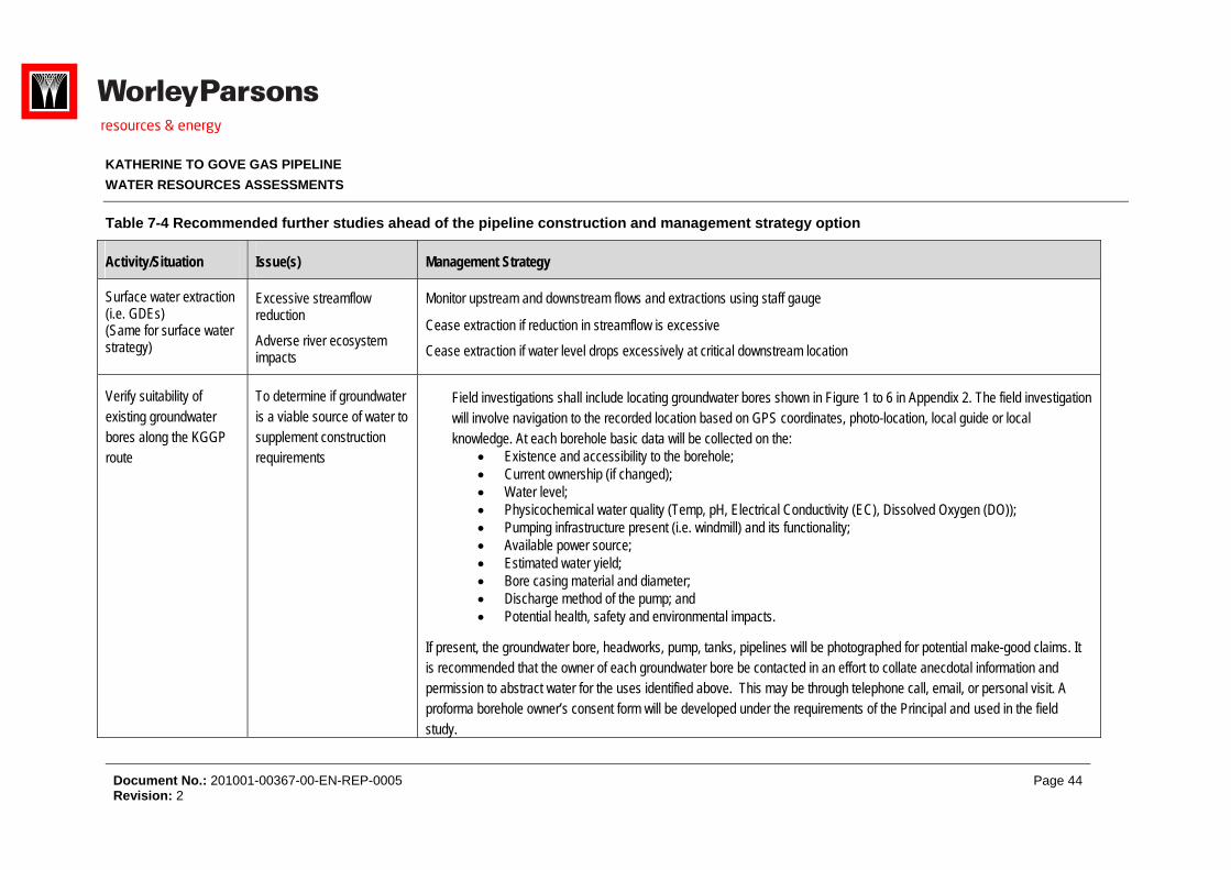
KATHERINE TO GOVE GAS PIPELINE
WATER RESOURCES ASSESSMENTS
Document No.: 201001-00367-00-EN-REP-0005 Page 44 Revision: 2
Table 7-4 Recommended further studies ahead of the pipeline construction and management strategy option
Activity/Situation Issue(s) Management Strategy
Surface water extraction (i.e. GDEs) (Same for surface water strategy)
Excessive streamflow reduction
Adverse river ecosystem impacts
Monitor upstream and downstream flows and extractions using staff gauge
Cease extraction if reduction in streamflow is excessive
Cease extraction if water level drops excessively at critical downstream location
Verify suitability of existing groundwater bores along the KGGP route
To determine if groundwater is a viable source of water to supplement construction requirements
Field investigations shall include locating groundwater bores shown in Figure 1 to 6 in Appendix 2. The field investigation will involve navigation to the recorded location based on GPS coordinates, photo-location, local guide or local knowledge. At each borehole basic data will be collected on the:
Existence and accessibility to the borehole; Current ownership (if changed); Water level; Physicochemical water quality (Temp, pH, Electrical Conductivity (EC), Dissolved Oxygen (DO)); Pumping infrastructure present (i.e. windmill) and its functionality; Available power source; Estimated water yield; Bore casing material and diameter; Discharge method of the pump; and Potential health, safety and environmental impacts.
If present, the groundwater bore, headworks, pump, tanks, pipelines will be photographed for potential make-good claims. It is recommended that the owner of each groundwater bore be contacted in an effort to collate anecdotal information and permission to abstract water for the uses identified above. This may be through telephone call, email, or personal visit. A proforma borehole owner’s consent form will be developed under the requirements of the Principal and used in the field study.
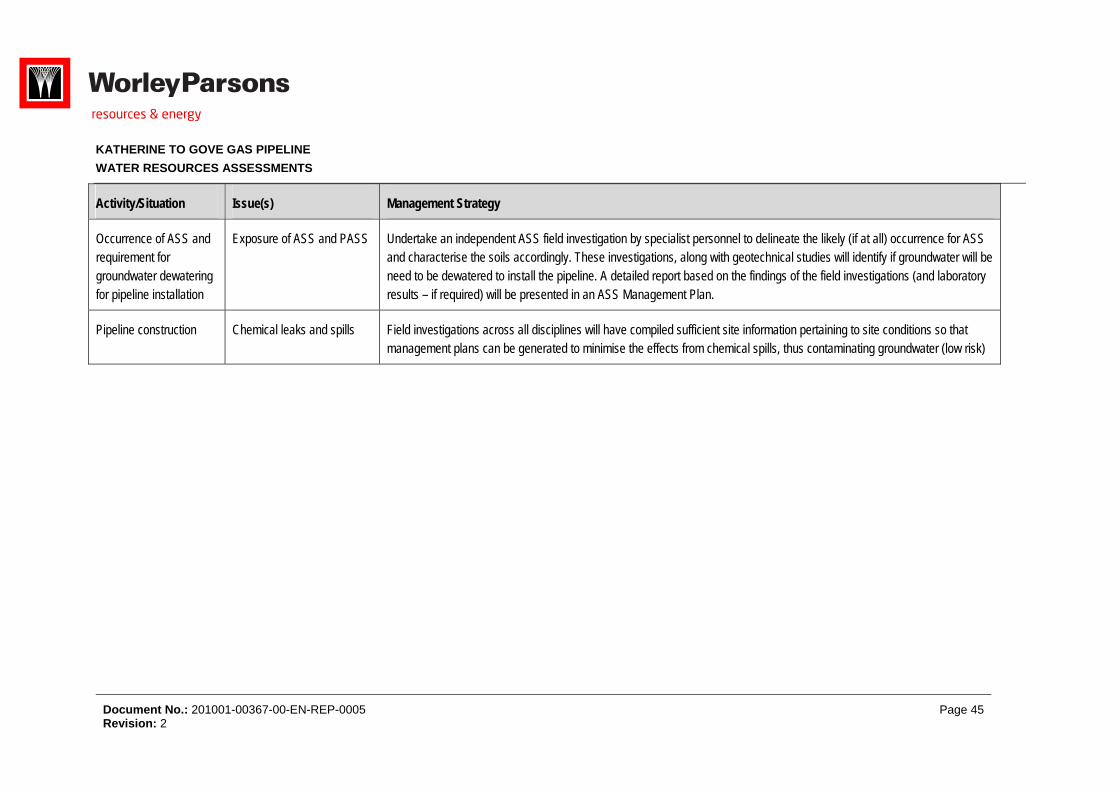
KATHERINE TO GOVE GAS PIPELINE
WATER RESOURCES ASSESSMENTS
Document No.: 201001-00367-00-EN-REP-0005 Page 45 Revision: 2
Activity/Situation Issue(s) Management Strategy
Occurrence of ASS and requirement for groundwater dewatering for pipeline installation
Exposure of ASS and PASS Undertake an independent ASS field investigation by specialist personnel to delineate the likely (if at all) occurrence for ASS and characterise the soils accordingly. These investigations, along with geotechnical studies will identify if groundwater will be need to be dewatered to install the pipeline. A detailed report based on the findings of the field investigations (and laboratory results – if required) will be presented in an ASS Management Plan.
Pipeline construction Chemical leaks and spills Field investigations across all disciplines will have compiled sufficient site information pertaining to site conditions so that management plans can be generated to minimise the effects from chemical spills, thus contaminating groundwater (low risk)
KATHERINE TO GOVE GAS PIPELINE
WATER RESOURCES ASSESSMENTS
Document No.: 201001-00367-00-EN-REP-0005 Page 46 Revision: 2
8 REFERENCES
Ahern C.R, Ahern M.R. and Powell B. 1998. Guidelines for Sampling and Analysis of Lowland Acid Sulfate Soils (ASS) in Queensland (1998). QASSIT. Department of Natural Resources, Resources Science Centre, Indooroopilly.
Australian & New Zealand Environment Conservation Council (ANZECC). 2000. National Water Quality Management Strategy: An introduction to the Australian and New Zealand guidelines for fresh and marine water quality. http://www.environment.gov.au/water/publications/quality/nwqms-introduction-4a.html.
Australian Drinking Water Guidelines (National Health and Medical Research Council (NHMRC) & Agriculture and Resource Management Council of Australia and New Zealand (ARMCANZ). http://www.nhmrc.gov.au/guidelines/publications/eh52
Dear S.E., Moore NG, Dobos SK, Watling K.M. and Ahern C.R. 2002. Soil Management Guidelines. In Queensland Acid Sulfate Soil Technical Manual. Department of Natural Resources and Mines; Indooroopilly, Queensland, Australia.
Department of Lands, Planning and Environment & Natural Resources Division (DLPE). 1999. Water Resources of East Arnhem Land. Report # 02/1999D.
Department of Lands, Planning and Environment & Natural Resources Division (DLPE). 2001. Water Resources of the Katherine Regions and South West Arnhem Land. Report # 28/2001D.
Department of Land Resource Management. 2013. Acid Sulfate Soils Risk Mapping – DLRM Data – Extract – North_250 (GDB).
Earth, Water, Life Sciences (EWLS). 2004. Impacts on Hydrology & Water Quality from the Trans Territory Pipeline Project’ – Appendix G of Draft EIS – EWL Sciences Pty Ltd, Oct 2004.
Eco Logical Australia. 2013. Katherine to Gove Gas Pipeline (KGGP) Environmental Impact Statement. Prepared on behalf of Pacific Aluminium.
Environment Protection and Heritage Council and the Natural Resource Management Ministerial Council. 2011. National guidance for the management of acid sulfate soils in inland aquatic ecosystems, Canberra, ACT.
Northern Territory of Australia Water Act. 2011. In force as of 7-November-2011
Natural Resources, Environment, the Arts and Sport (NRETAS). Fact sheet: Beneficial Use Declarations. www.nt.gov.au/nretas/water/manage
National Water Commission (NWC). 2005. ‘Australian Water Resources 2005’ - National Water Commission. 2005
Northern Territory Government (NTG). 2009. ‘Water Resources of the Roper River Region’ - Northern Territory Government. 2009
KATHERINE TO GOVE GAS PIPELINE
WATER RESOURCES ASSESSMENTS
Document No.: 201001-00367-00-EN-REP-0005 Page 47 Revision: 2
Sinclair Knight Merz (SKM). 2011. Australian groundwater-dependent ecosystems toolbox part1: assessment framework. Waterlines Report Series No 69, December, 2011. Report prepared on behalf of the National Water Commission.
Woodside Energy & Alcan Gove. 2004. Draft Environmental Impact Statement: Trans Territory Underground Pipeline.
WorleyParsons. 2012. Katherine to Gove Gas Pipeline: Constructability Workshop Outputs Report (dated 20/12/12). Report prepared by WorleyParsons on behalf of Pacific Aluminium Report # 201001-00367-CM-REP-0001
Zaar, U., G Prowse and I Matthews.1999. ‘Water Resources of East Arnhem Land’ Report 02/199D –Sept 1999
Zaar. 2003. ‘Water Resources of West Arnhem Land’ Report 34/2003D –2003

KATHERINE TO GOVE GAS PIPELINE
WATER RESOURCES ASSESSMENTS
Document No.: 201001-00367-00-EN-REP-0005 Appendix Page 1 Revision: 2
Appendix 1 – Surface Water Maps
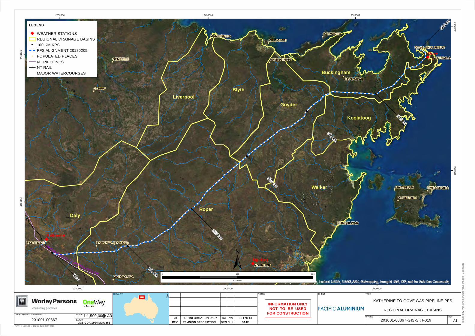
"
"
"
"
"
"
"
"
"
"
"
"
"
"
"
"
"
"
"
"
"
AMADEUS BASIN TO DARWIN PIPELINE
KATHERINE BARUNGA (BAMYILI)
MATARANKA
GAPUWIYAK
UMBAKUMBA
NUMBULWAR
OENPELLI
JABIRU
MANINGRIDAMILINGIMBI
RAMINGINING
ALYANGULA
ANGURUGU
NHULUNBUY
YIRRKALA
NGUKURR
GALIWINKU
GOVE
0 km
100 km
200 km
300 km
400 km
500 km
600 k
m
DalyRoper
Walker
Koolatoog
Goyder
BlythLiverpool
Buckingham
Gove
Katherine
Ngukurr
Source: Esri, DigitalGlobe, GeoEye, i-cubed, USDA, USGS, AEX, Getmapping, Aerogrid, IGN, IGP, and the GIS User Community
2200000
2200000
2400000
2400000
2600000
2600000
8399
984
8399
984
8599
984
8599
984
DRG NO
PATH: ..201001-00367-GIS-SKT-019
TITLE
CHKDRN
CLIENT
DATERW 18-Feb-13
A1REV
REV REVISION DESCRIPTION
LOCALITY
A1 FOR INFORMATION ONLY
±0 100 200
Kilometres
LEGEND" WEATHER STATIONS
REGIONAL DRAINAGE BASINS100 KM KPSPFS ALIGNMENT 20130205
" POPULATED PLACESNT PIPELINESNT RAILMAJOR WATERCOURSES
INFORMATION ONLYNOT TO BE USED
FOR CONSTRUCTION
Pro
duce
d by
ryan
.wrig
ht@
wor
leyp
arso
ns.c
om, G
eom
atic
s
NOTES
WORLEYPARSONS PROJECT
DATUM
SCALE @ A31:1,500,000
GCS GDA 1994 MGA z53
KATHERINE TO GOVE GAS PIPELINE PFS
REGIONAL DRAINAGE BASINS
201001-00367-GIS-SKT-019AW
±
201001-00367
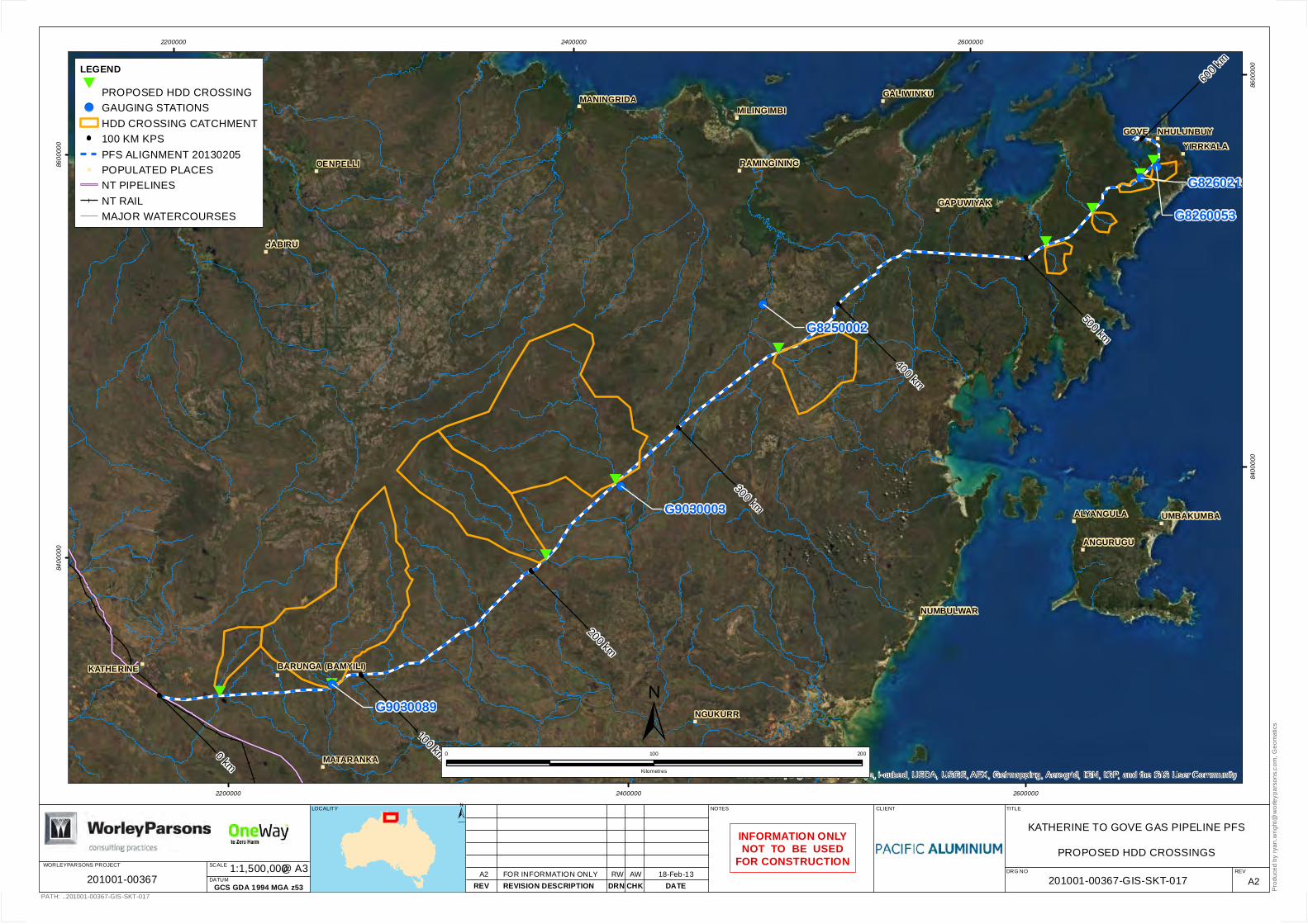
"
"
"
"
"
"
"
"
"
"
"
"
"
"
"
"
"
"
#
#
#
#
#
#
#
#
#
!(
!(!(
!(
!(
KATHERINE BARUNGA (BAMYILI)
MATARANKA
GAPUWIYAK
UMBAKUMBA
NUMBULWAR
OENPELLI
JABIRU
MANINGRIDAMILINGIMBI
RAMINGINING
ALYANGULA
ANGURUGU
NHULUNBUYYIRRKALA
NGUKURR
GALIWINKU
GOVE
0 km
100 km
200 km
300 km
400 km
500 km
600 k
m
G8250002
G8260053
G8260219
G9030003
G9030089
Source: Esri, DigitalGlobe, GeoEye, i-cubed, USDA, USGS, AEX, Getmapping, Aerogrid, IGN, IGP, and the GIS User Community
2200000
2200000
2400000
2400000
2600000
2600000
8400
000
8400
000
8600
000
8600
000
DRG NO
PATH: ..201001-00367-GIS-SKT-017
TITLE
CHKDRN
CLIENT
DATERW 18-Feb-13
A2REV
REV REVISION DESCRIPTION
LOCALITY
A2 FOR INFORMATION ONLY
±0 100 200
Kilometres
LEGEND#
PROPOSED HDD CROSSING!( GAUGING STATIONS
HDD CROSSING CATCHMENT100 KM KPSPFS ALIGNMENT 20130205
" POPULATED PLACESNT PIPELINESNT RAILMAJOR WATERCOURSES
INFORMATION ONLYNOT TO BE USED
FOR CONSTRUCTION
Pro
duce
d by
ryan
.wrig
ht@
wor
leyp
arso
ns.c
om, G
eom
atic
s
NOTES
WORLEYPARSONS PROJECT
DATUM
SCALE @ A31:1,500,000
GCS GDA 1994 MGA z53
KATHERINE TO GOVE GAS PIPELINE PFS
PROPOSED HDD CROSSINGS
201001-00367-GIS-SKT-017AW
±
201001-00367
KATHERINE TO GOVE GAS PIPELINE
WATER RESOURCES ASSESSMENTS
Document No.: 201001-00367-00-EN-REP-0005 Appendix Page 2 Revision: 2
Appendix 2 – Existing Groundwater Bores Along The KGGP

#
#
#
#
"
"
$+
$+
$+
$+
$+
$+
$+
$+
$+
$+
$+
$+$+$+
$+
$+$+
$+
$+
$+
$+
$+
$+ $+
$+
$+
$+
$+
$+
$+
$+
$+ $+
$+
$+
$+
$+
$+$+
$+
$+
$+$+$+$+
$+
$+
$+$+
$+$+$+
$+
$+
$+
$+
$+
$+
$+$+
$+$+
$+
$+
$+
$+ $+
$+$+
$+ $+
$+
$+
$+
$+$+
$+$+
$+
$+
$+
$+$+
$+
$+
$+
$+
$+$+$+$+$+
$+$+
$+
$+
$+
$+
$+
$+
$+
$+
$+$+
$+
$+$+$+$+$+$+$+$+ $+
$+
$+
$+
$+
$+ $+
$+
$+
$+
$+
$+
$+
$+
$+
$+
$+
$+$+
$+
$+
$+
$+
$+ $+
$+
$+$+
$+
$+
$+
$+
$+
$+$+$+$+$+
$+
$+
$+
$+$+$+
$+
$+$+$+
$+
$+$+ $+
$+
$+
$+
$+
$+
$+
$+$+
$+
$+ $+
$+
$+$+
$+$+$+$+
$+
$+
$+$+$+
$+$+
$+
$+$+
$+
$+
$+
$+
$+
$+
$+$+$+$+
$+
$+
$+
$+$+$+
$+$+$+
$+
$+$+$+$+$+
$+
$+$+
$+
$+$+$+$+$+$+
$+$+$+$+ $+$+$+$+$+$+$+
$+$+
$+$+$+$+$+
$+
$+
$+$+
$+$+$+
$+$+
$+
$+$+$+$+$+
$+
$+
$+
$+
$+
$+$+$+$+$+$+$+$+$+$+$+$+$+$+
$+
$+ $+
$+$+$+
$+$+$+$+$+$+
$+
$+
$+$+$+
$+
$+
$+$+
$+$+
$+
$+$+
$+
$+
$+$+
$+$+$+
$+$+
$+
$+
$+$+
$+$+
$+$+
$+
$+
$+
$+
$+
$+
$+ $+
$+
$+
$+$+
$+
$+
$+
$+$+
$+
$+
$+$+
$+
$+
$+
$+
$+
$+$+
$+
$+
$+
$+$+$+$+
$+$+
$+$+
$+$+$+$+$+$+
$+
$+$+
$+$+$+$+$+
$+$+$+
$+
$+
$+
$+
$+$+
$+
$+$+$+$+
$+$+$+
$+
$+
$+
$+
$+
$+
$+
$+
$+
$+$+$+
$+
$+$+$+
$+$+
$+
$+$+$+$+
$+
$+
$+$+
$+$+ $+$+$+$+
$+ $+$+
$+
$+
$+
$+$+
$+
$+$+
$+
$+$+
$+
$+$+
$+
$+$+$+
$+
$+
$+$+
$+$+
$+
$+$+
$+
$+$+
$+$+
$+
$+
$+
$+
$+
$+
$+
$+
$+
$+$+
$+
$+
$+
$+
$+
$+
$+
$+
$+
$+
$+
$+$+$+
$+$+$+
$+$+
$+$+
$+
$+
$+
$+
$+
$+
$+
$+
$+
$+$+
$+
$+
$+$+
$+
$+
$+ $+$+$+$+$+$+$+
$+
$+$+
$+
$+
$+
$+$+ $+
$+
$+
$+$+
$+$+
$+
$+
$+$+
$+$+
$+
$+
$+
$+
$+
$+$+ $+$+
$+$+$+
$+
$+
$+
$+
$+$+
$+ $+
$+
$+
$+
$+
$+
$+$+
$+
$+
$+
$+
$+
$+$+
$+
$+
$+
$+
$+
$+ $+
$+
$+$+
$+
$+
$+
$+
$+$+
$+
$+
$+$+$+$+
$+ $+
$+
$+
$+
$+$+
$+
$+
$+$+$+
$+$+
$+
$+
$+$+$+$+
$+
$+
$+
$+
$+
$+
$+$+$+
$+$+$+
$+
$+
$+
$+$+$+
$+
$+
$+
$+
$+$+
$+$+$+$+$+$+
$+$+$+$+
$+
$+
$+
$+
$+$+
$+$+
$+$+
$+$+
$+$+
$+$+
$+
$+
$+
$+
$+$+$+$+
$+$+
$+$+
$+$+
$+$+
$+$+
$+
$+
$+
$+$+$+$+$+$+$+$+
$+
$+ $+$+
$+
$+
$+
$+
$+$+
$+
$+
$+
$+
$+
$+$+
$+
$+
$+
$+
$+$+$+
$+$+
$+$+
$+
$+
$+
$+
$+$+
$+
$+
$+
$+
$+
$+
$+
$+
$+
$+
$+
$+
$+$+$+
$+
$+$+
$+$+
$+
$+$+
$+
$+
$+
$+
$+
$+
$+
$+
$+
$+
$+$+
$+$+$+
$+
$+$+$+$+
$+
$+
$+ $+$+
$+
$+
$+$+
$+
$+$+
$+
ALICE SPRINGS DARWIN RAILWAYAMADEUS BASIN TO DARWIN PIPELINE
MINIALAPARK
KUMBIDGEE
MATARANKASTATION
MAUDCREEK
EVA
VALL
EYRO
AD
BARUNGA
UR
ALL
A R
OA
D
TINDAL AIRPORT
QU
ARR
YR
OA
D
FOX ROADKIN
GR
IVE
R
GORGE ROAD
C E NTRAL ARNHE M ROAD
STUART HIGHWAY
0 km10 km
20 km
30 km
40 km
50 km60 km
70 km80 km
90 km
AB C
D
DF
G
G
H
I J
K
Copyright ©WorleyParsons Services Pty Ltd
ABN 61 001 279 812REV DATE REVISION DESCRIPT ION REF DRAWING No REFERENCE DRAWING TITLE
..201001-00367 KGGP PFS\03Project\Workspace\_SKT\201001-00367-GIS-SKT-021.mxd
CUSTOMER
KATHERINE GOVE GAS PIPELINE
IDENTIFIED BORE HOLES
DRAWING No REV
"
"
"
"
"0 km
500 km400 km300 km
200 km100 km
JABIRU
NGUKURR
NHULUNBUY
GAPUWIYAK
KATHERINE
DRAWN DRAFT CHK DESIGNED ENG CHK REVIEWED APPROVED 201001-00367-GIS-SKT-021
20 010
Kilometers
PROJECT No
1:300,000SCALEA3 SHEET
Produ
ced b
y: RY
AN.W
RIGH
T@W
ORLE
YPAR
SONS
.COM
- Geo
matic
s
NOTES
±
201012-00367 A
LEGEND10KM KP
PFS ALIGNMENT 20130205
$+ IDENTIFIED BORE HOLES
NO DATA / POOR YIELD
$+
WATER BOREECOLOGICAL STUDY 2000-2001
" POPULATED PLACES
# HOMESTEADS
ROADS
PIPELINE
RAIL
ISSUED FOR INTERNAL REVIEW20-Feb-13A RW TC
±LOCALITY MAP
PRELIMINARYUNCHECKED
INFORMATION ONLYNOT TO BE USED
FOR CONSTRUCTION
UNCONTROLLEDCOPY
PAGE 1 OF 6
IMAGERY: LANDSAT
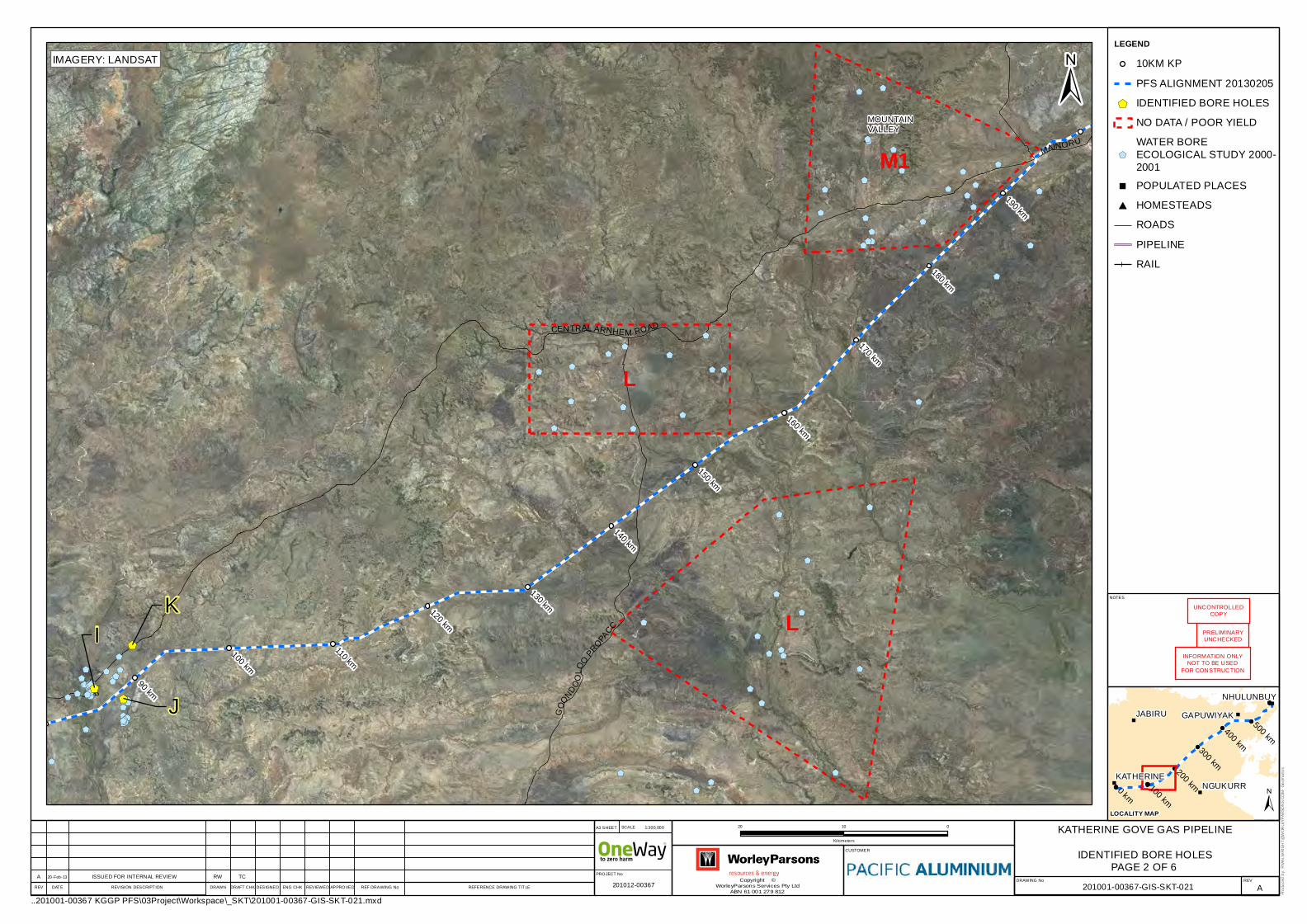
#
$+$+$+$+ $+$+$+
$+
$+$+
$+
$+
$+
$+
$+
$+
$+
$+
$+
$+
$+
$+
$+
$+
$+
$+
$+
$+
$+
$+
$+
$+
$+
$+
$+
$+
$+
$+$+
$+
$+
$+
$+
$+
$+
$+
$+
$+
$+
$+
$+
$+$+
$+$+$+
$+
$+
$+
$+
$+
$+$+$+$+$+$+
$+$+$+$+$+
$+$+$+
$+$+$+
$+$+$+$+
$+$+
$+
$+
$+
$+
$+
$+
$+$+$+$+$+$+$+$+$+$+$+$+$+$+
$+$+$+$+
$+$+$+$+$+$+
$+$+$+
$+
$+
$+
$+
$+
$+$+ $+
$+
$+$+
$+
MOUNTAINVALLEY
MAINORU
GOO
NDOO
LOO
PROPACC
CENTRAL ARNHEM ROAD
90 km
100 km
110 km
120 km
130 km
140 km
150 km
160 km
170 km
180 km
190 km
I
J
K
M1
L
L
Copyright ©WorleyParsons Services Pty Ltd
ABN 61 001 279 812REV DATE REVISION DESCRIPT ION REF DRAWING No REFERENCE DRAWING TITLE
..201001-00367 KGGP PFS\03Project\Workspace\_SKT\201001-00367-GIS-SKT-021.mxd
CUSTOMER
KATHERINE GOVE GAS PIPELINE
IDENTIFIED BORE HOLES
DRAWING No REV
"
"
"
"
"0 km
500 km400 km300 km
200 km100 km
JABIRU
NGUKURR
NHULUNBUY
GAPUWIYAK
KATHERINE
DRAWN DRAFT CHK DESIGNED ENG CHK REVIEWED APPROVED 201001-00367-GIS-SKT-021
20 010
Kilometers
PROJECT No
1:300,000SCALEA3 SHEET
Produ
ced b
y: RY
AN.W
RIGH
T@W
ORLE
YPAR
SONS
.COM
- Geo
matic
s
NOTES
±
201012-00367 A
LEGEND10KM KP
PFS ALIGNMENT 20130205
$+ IDENTIFIED BORE HOLES
NO DATA / POOR YIELD
$+
WATER BOREECOLOGICAL STUDY 2000-2001
" POPULATED PLACES
# HOMESTEADS
ROADS
PIPELINE
RAIL
ISSUED FOR INTERNAL REVIEW20-Feb-13A RW TC
±LOCALITY MAP
PRELIMINARYUNCHECKED
INFORMATION ONLYNOT TO BE USED
FOR CONSTRUCTION
UNCONTROLLEDCOPY
PAGE 2 OF 6
IMAGERY: LANDSAT

#
#
#
#
#
#
$+
$+$+
$+
$+
$+$+
$+
$+
$+
$+
$+
$+
$+
$+
$+
$+
$+
$+$+
$+
$+
$+
$+
$+
$+
$+$+$+$+
$+$+$+$+
$+$+$+ $+$+
$+$+$+$+$+$+$+
$+
$+$+$+$+
$+
MAINORU
MOBARN
MOUNTJEAN
MOUNTAINVALLEY
BAGHETTI
MOUNTCATT
BULMANWEEMOL
MOUNT JEAN
GORPULYU
L
MOBARN
MAINORU
MOUNT CATT
MANINGRIDAACCESS
MAINORU/WONGALARA
CENTRAL ARNHEMROAD
200 km
210 km
220 km
230 km
240 km
250 km
260 km
270 km
280 km
290 km
M1
N
O
P
Copyright ©WorleyParsons Services Pty Ltd
ABN 61 001 279 812REV DATE REVISION DESCRIPT ION REF DRAWING No REFERENCE DRAWING TITLE
..201001-00367 KGGP PFS\03Project\Workspace\_SKT\201001-00367-GIS-SKT-021.mxd
CUSTOMER
KATHERINE GOVE GAS PIPELINE
IDENTIFIED BORE HOLES
DRAWING No REV
"
"
"
"
"0 km
500 km400 km300 km
200 km100 km
JABIRU
NGUKURR
NHULUNBUY
GAPUWIYAK
KATHERINE
DRAWN DRAFT CHK DESIGNED ENG CHK REVIEWED APPROVED 201001-00367-GIS-SKT-021
20 010
Kilometers
PROJECT No
1:300,000SCALEA3 SHEET
Produ
ced b
y: RY
AN.W
RIGH
T@W
ORLE
YPAR
SONS
.COM
- Geo
matic
s
NOTES
±
201012-00367 A
LEGEND10KM KP
PFS ALIGNMENT 20130205
$+ IDENTIFIED BORE HOLES
NO DATA / POOR YIELD
$+
WATER BOREECOLOGICAL STUDY 2000-2001
" POPULATED PLACES
# HOMESTEADS
ROADS
PIPELINE
RAIL
ISSUED FOR INTERNAL REVIEW20-Feb-13A RW TC
±LOCALITY MAP
PRELIMINARYUNCHECKED
INFORMATION ONLYNOT TO BE USED
FOR CONSTRUCTION
UNCONTROLLEDCOPY
PAGE 3 OF 6
IMAGERY: LANDSAT

#
$+
$+$+$+
$+
$+
$+
$+
BARRAPUNTA
RA
MIN
GIN
ING
/CE
NT R
AL
AR
NHEM
RO
AD
CENTRAL ARNHEM ROAD
290 km
300 km
310 km
320 km
330 km
340 km
350 km
360 km
370 km
380 km
390 km
Copyright ©WorleyParsons Services Pty Ltd
ABN 61 001 279 812REV DATE REVISION DESCRIPT ION REF DRAWING No REFERENCE DRAWING TITLE
..201001-00367 KGGP PFS\03Project\Workspace\_SKT\201001-00367-GIS-SKT-021.mxd
CUSTOMER
KATHERINE GOVE GAS PIPELINE
IDENTIFIED BORE HOLES
DRAWING No REV
"
"
"
"
"0 km
500 km400 km300 km
200 km100 km
JABIRU
NGUKURR
NHULUNBUY
GAPUWIYAK
KATHERINE
DRAWN DRAFT CHK DESIGNED ENG CHK REVIEWED APPROVED 201001-00367-GIS-SKT-021
20 010
Kilometers
PROJECT No
1:300,000SCALEA3 SHEET
Produ
ced b
y: RY
AN.W
RIGH
T@W
ORLE
YPAR
SONS
.COM
- Geo
matic
s
NOTES
±
201012-00367 A
LEGEND10KM KP
PFS ALIGNMENT 20130205
$+ IDENTIFIED BORE HOLES
NO DATA / POOR YIELD
$+
WATER BOREECOLOGICAL STUDY 2000-2001
" POPULATED PLACES
# HOMESTEADS
ROADS
PIPELINE
RAIL
ISSUED FOR INTERNAL REVIEW20-Feb-13A RW TC
±LOCALITY MAP
PRELIMINARYUNCHECKED
INFORMATION ONLYNOT TO BE USED
FOR CONSTRUCTION
UNCONTROLLEDCOPY
PAGE 4 OF 6
IMAGERY: LANDSAT

#
# #
#
"$+$+$+$+$+$+$+
$+
$+ $+
$+$+
$+
$+
$+
$+
$+
$+$+$+
$+
$+$+$+
$+
$+
$+
$+
GAPUWIYAK
DHUNGANDA
MIRRNATJA
DHAMIYAKA ACCESS
GAL ING
AR BULA
RRI
NG
DHUNGANDA
BAR
GELAND
ING
ROAD
MIR RNATJA
GAN GAN
DHUPUWAMIRRI
GA
PUW
IYA
KR
OA
DGULBUWANG AY
BUL ARRING
GO
VE/N
UM
BU
LWA
R
BALINGURA
CENTRAL ARNHEM ROAD
380 km
390 km
400 km
410 km
420 km
430 km
440 km
450 km460 km
470 km480 km
Q
R
Q1
Copyright ©WorleyParsons Services Pty Ltd
ABN 61 001 279 812REV DATE REVISION DESCRIPT ION REF DRAWING No REFERENCE DRAWING TITLE
..201001-00367 KGGP PFS\03Project\Workspace\_SKT\201001-00367-GIS-SKT-021.mxd
CUSTOMER
KATHERINE GOVE GAS PIPELINE
IDENTIFIED BORE HOLES
DRAWING No REV
"
"
"
"
"0 km
500 km400 km300 km
200 km100 km
JABIRU
NGUKURR
NHULUNBUY
GAPUWIYAK
KATHERINE
DRAWN DRAFT CHK DESIGNED ENG CHK REVIEWED APPROVED 201001-00367-GIS-SKT-021
20 010
Kilometers
PROJECT No
1:300,000SCALEA3 SHEET
Produ
ced b
y: RY
AN.W
RIGH
T@W
ORLE
YPAR
SONS
.COM
- Geo
matic
s
NOTES
±
201012-00367 A
LEGEND10KM KP
PFS ALIGNMENT 20130205
$+ IDENTIFIED BORE HOLES
NO DATA / POOR YIELD
$+
WATER BOREECOLOGICAL STUDY 2000-2001
" POPULATED PLACES
# HOMESTEADS
ROADS
PIPELINE
RAIL
ISSUED FOR INTERNAL REVIEW20-Feb-13A RW TC
±LOCALITY MAP
PRELIMINARYUNCHECKED
INFORMATION ONLYNOT TO BE USED
FOR CONSTRUCTION
UNCONTROLLEDCOPY
PAGE 5 OF 6
IMAGERY: LANDSAT
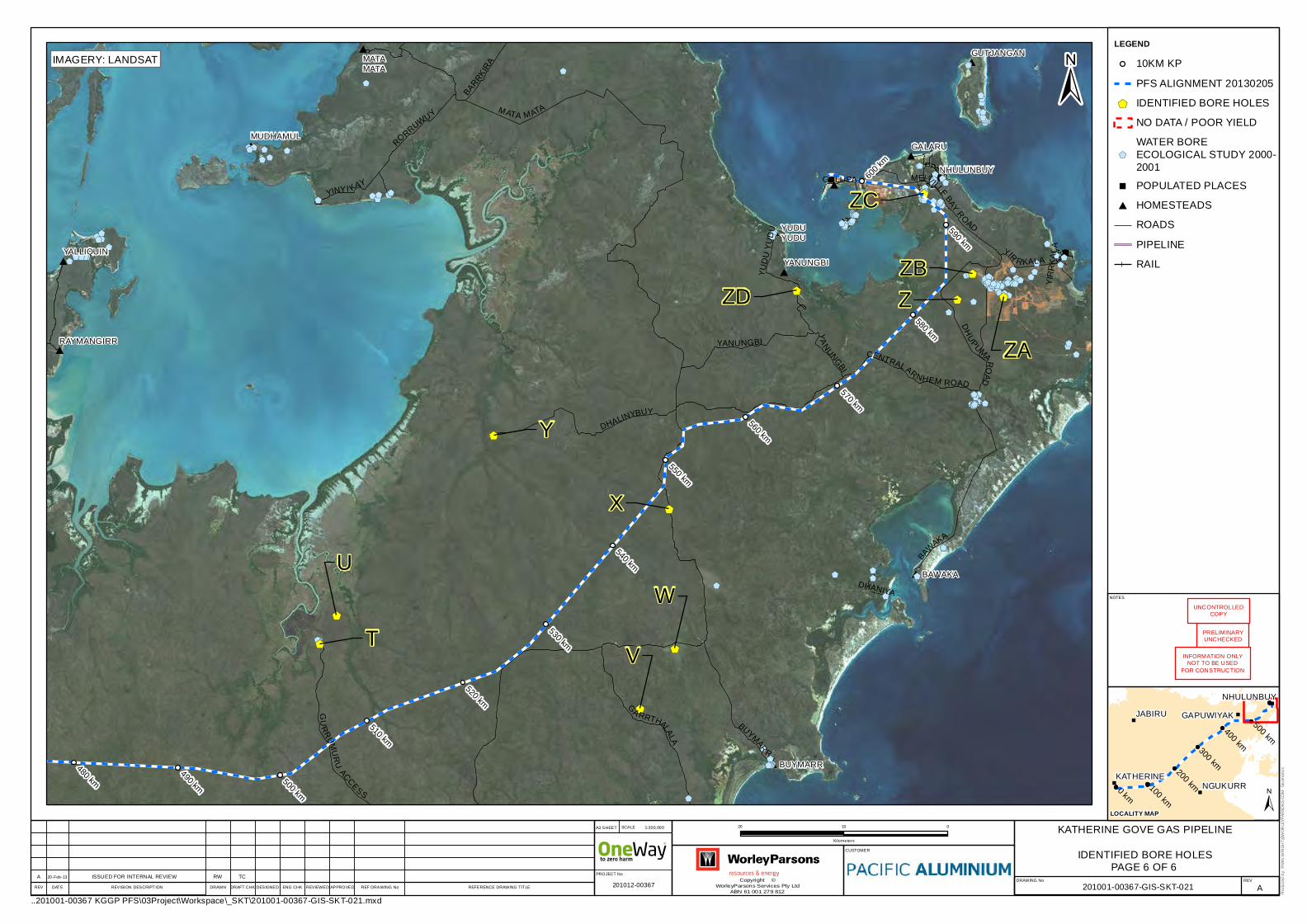
#
#
#
#
#
#
#
#
#
#
#
#
"
"
"
$+$+$+$+
$+
$+$+$+$+
$+
$+$+$+$+$+
$+$+
$+
$+$+$+$+$+$+$+$+$+$+$+$+$+$+$+$+$+$+$+$+$+$+$+$+$+$+$+$+$+$+$+$+$+$+$+ $+$+$+$+$+$+$+$+$+
$+$+$+$+$+$+$+$+$+$+$+$+$+
$+
$+$+
$+$+$+$+$+$+$+$+$+
$+$+$+$+$+
$+$+$+$+$+$+$+
$+$+
$+$+$+$+
$+$+
$+$+$+$+$+
$+
$+
$+
$+$+
$+$+
$+
$+$+
$+$+$+
$+$+$+
$+$+$+
$+$+$+$+$+ $+
$+$+$+$+$+$+$+$+$+$+$+$+$+$+$+
$+$+
$+$+$+$+$+$+
$+$+$+$+$+$+
$+$+$+$+
$+$+$+
$+$+$+$+$+
$+$+$+$+
$+
$+
$+
$+$+
$+$+$+
$+
$+
$+
$+
$+$+$+$+$+$+
$+
$+$+$+
$+$+$+$+
$+$+$+$+$+$+$+
$+
$+$+$+
$+$+$+$+$+$+$+$+$+
$+
$+$+
$+$+$+
$+$+
$+$+
$+
$+$+$+
$+
$+$+$+$+$+
$+
$+
$+
$+$+
$+
$+
$+$+
$+$+
$+
$+
$+
$+$+
$+$+$+$+
$+
$+$+$+$+$+
$+$+
$+$+$+
$+$+
$+
$+
$+
$+
$+$+
$+$+
$+
$+$+$+
$+
$+
$+
$+
$+
$+
$+
$+ $+
$+
$+
$+
NHULUNBUY
YALLIQUIN
BAWAKA
MUDHAMUL
MATAMATA
YANUNGBI
GALARU
RAYMANGIRR
BUYMARR
GUTJANGAN
YUDUYUDU
YIR
RKALA
GALUPA
YIR
RK
ALA
DHANIYA
YU
DU
YU
DU
YA
NUNGBIBARRKIR
A
YINYI KAY
RORRUWUY
BUYMAR
R
DH
UPUMAR
OAD
GU
RR
UMU
RU
ACCESS
G
A RRTHALALA
DHALINYBUY
BAWAKA
MELVILLEBAY
ROAD
YANUNGBI
MATA MATA
CENTRALARNHEM ROAD
480 km490 km
500 km
510 km
520 km
530 km
540 km
550 km
560 km
570 km
580 km
590 km
600 k
m
T
U
V
W
X
Y
Z
ZA
ZB
ZC
ZD
Copyright ©WorleyParsons Services Pty Ltd
ABN 61 001 279 812REV DATE REVISION DESCRIPT ION REF DRAWING No REFERENCE DRAWING TITLE
..201001-00367 KGGP PFS\03Project\Workspace\_SKT\201001-00367-GIS-SKT-021.mxd
CUSTOMER
KATHERINE GOVE GAS PIPELINE
IDENTIFIED BORE HOLES
DRAWING No REV
"
"
"
"
"0 km
500 km400 km300 km
200 km100 km
JABIRU
NGUKURR
NHULUNBUY
GAPUWIYAK
KATHERINE
DRAWN DRAFT CHK DESIGNED ENG CHK REVIEWED APPROVED 201001-00367-GIS-SKT-021
20 010
Kilometers
PROJECT No
1:300,000SCALEA3 SHEET
Produ
ced b
y: RY
AN.W
RIGH
T@W
ORLE
YPAR
SONS
.COM
- Geo
matic
s
NOTES
±
201012-00367 A
LEGEND10KM KP
PFS ALIGNMENT 20130205
$+ IDENTIFIED BORE HOLES
NO DATA / POOR YIELD
$+
WATER BOREECOLOGICAL STUDY 2000-2001
" POPULATED PLACES
# HOMESTEADS
ROADS
PIPELINE
RAIL
ISSUED FOR INTERNAL REVIEW20-Feb-13A RW TC
±LOCALITY MAP
PRELIMINARYUNCHECKED
INFORMATION ONLYNOT TO BE USED
FOR CONSTRUCTION
UNCONTROLLEDCOPY
PAGE 6 OF 6
IMAGERY: LANDSAT

KATHERINE TO GOVE GAS PIPELINE
WATER RESOURCES ASSESSMENTS
Document No.: 201001-00367-00-EN-REP-0005 Appendix Page 3 Revision: 2
Appendix 3 – Acid Sulfate Soils Risk Map Results

Acid Sulfaate Soils (ASS) riskk mapping along the KGGP (Eco Loggical. 2013)


![Financial Mathematics - University of Minnesotaadams005/MATH1271/TopicsMATH1271/...QED — [det(R)] [det(Rt)] = det(RRt) = det(l) = 1 Definitions of determinant 1 called a reflection.](https://static.fdocuments.us/doc/165x107/5af71f277f8b9a92719133b0/financial-mathematics-university-of-minnesota-adams005math1271topicsmath1271qed.jpg)


