2010 toughbox user guide - Yahoo
14
www.andymark.com 1 2010 Toughbox User Guide AndyMark, Inc. Components Used in 2010 FIRST Robotics Competition
Transcript of 2010 toughbox user guide - Yahoo

www.andymark.com 1
2010 Toughbox
User Guide AndyMark, Inc. Components Used in
2010 FIRST Robotics Competition

www.andymark.com 2
Contents Page
1. Overview 3
2. Toughbox Overview 4
3. Toughbox Specifications 4
4. Toughbox Bill of Material and Part Photos 5, 6
5. Toughbox Exploded View 7
6. Toughbox Assembly Instructions 8, 9, 10
7. Encoder Assembly onto Toughbox 11, 12
8. Battery Plug Usage 13
9. Background on AndyMark 14

www.andymark.com 3
1. Overview
The Toughbox is a standard AndyMark gearbox. For the 2010 FRC Kit of Parts, new
components of the Toughbox include a grease pack and mounting hardware for the US Digital
encoder.
Each registered FRC team will receive parts for two Toughboxes. The Toughboxes are
provided in kit form, with assembly required. CAD files and more detailed layout drawings can
be found at www.andymark.com.

www.andymark.com 4
2. Toughbox Overview
3. Toughbox Specifications
Gears AGMA 6-8 20 dp, 14.5 deg. pressure angle cold formed 4140 steel
Gear sizes
CIM Gear: 14 tooth (0.314” id w/ 2mm keyway) Large Cluster Gear: 50 tooth (3/8” hex bore) Small Cluster Gear: 14 tooth (3/8” hex bore) Large Output Gear: 50 tooth (1/2” hex bore)
Gear ratios 12.76:1 total, 50/14 * 50/14 = 12.755
Output shaft
½” diameter 4140 steel shaft, with 1/8” wide keyway ¼-20 x ½” deep threaded hole on end 1 machine key, 1 washer, and 1 ¼-20 screw are all provided
The AndyMark Toughbox gearbox (am-0145)
is designed for use in the 2010 FIRST Robotics
Competition (FRC). Each FRC team will receive
two (2) Toughboxes in their Kit of Parts (KoP).
The Toughbox is provided in kit form, with
assembly required. Full assembly instructions can
be found in this manual. Each Toughbox provided
includes all parts to mount two 2.5” CIM Motors
(provided in FRC KoP). Each Toughbox can use
two of the 2.5” CIM Motors as input devices. The
US Digital encoder provided in the KoP fits onto
the Toughbox by using the included encoder
mount pad.
Additional Toughboxes and hardware can be
purchased at www.andymark.com. CAD files (.stp
version) are available at this same site.
Optional gear ratios, shafts, and lightening features are available as optional parts at the www.andymark.com website.

www.andymark.com 5
4. Toughbox Bill of Material
Item # Component Qty Part Number Part Photo
1 Mount Plate 1 am-0155
2 Shaft Plate 1 am-0261
3 Output Shaft
1 am-0153
4 Extrusion Cover
1 am-0260
5
Large Cluster Gear
(3/8 hex bore)
1 am-0149
6
Large Output Gear
(1/2 hex bore)
1 am-0150
7 Small Hex Shaft 1 am-0152
8 Small Cluster Gear
(3/8 hex bore) 1 am-0151
9 CIM Gear 2 am-0034
10 FR6ZZ bearing 3 am-0028

www.andymark.com 6
11 FR8ZZ bearing 1 am-0030
12 ¼ - 20 x 2 shcs 4 am-1012
13 ¼ - 20 nylock nut 4 am-1015
14 ¼” washer 1 am-1027
15 ¼ - 20 x ½ bhcs 1 am-1029
16 #10-32 x 5/8” shcs w/ nylock 4 am-1120
17 #10-32 x ½ shcs 2 am-1002
18 2x2x10mm key 2 am-1121
19 1/8" machine key 1 am-1043
20 5/16 washer 4 am-1009
21 ½” e-Klip 1 am-0206
22 8mm Retainer Clip 2 am-0033
23 Grease Pack 1 am-0448
24 Encoder Mount 1 am-0208

www.andymark.com 7
5. Exploded View
2
1
15
3
6 8
5
7
9
4
19
13
10
20
12
22
21
18
17
16
11
2010 AndyMark Toughbox – Exploded View
Not Pictured:
23 - Grease Pack
24 - Encoder Mount
2.5” CIM Motors
not included with
Toughbox
14

www.andymark.com 8
6. Assembly Instructions
Tools needed: 5/16” allen wrench 3/16” allen wrench 7/16” wrench (or socket driver) Small hammer
Step 1: Ensure you have all parts listed in the Toughbox BOM and shown in Fig. 1.
Step 2: Insert two of the 5/16” washers, the 2x2x10mm machine key, CIM Gear, and 5/16” clip
onto CIM Motor shaft, shown in Fig. 2.
Step 3. Press two of the FR6ZZ bearings into the Mount Plate. Press a FR6ZZ and FR8ZZ
bearing into the shaft plate. Use an arbor press, a strong push with a thumb, or light taps with
a small hammer. Check that flanges are on the same side.
Assembly tools needed
Fig. 1
Fig. 2
Fig. 3a
Fig. 3b

www.andymark.com 9
Step 4. Mount motor to Mount Plate using #10-32 screws. DO NOT ADD Loctite or other
thread locking material. This has already been applied to the screws (excess Loctite or other
thread locking material will eat away the polycarbonate). Make sure that the bearing flanges
are not on the same side as the motor.
Step 5. Attach the ½” E-Klip into the groove on the Output Shaft.
Step 6. Place the Small Hex Shaft into the bearing closest to the motor pinion. Place the
Large Cluster Gear (with the smaller hex hole) onto the Small Hex Shaft. Make sure the teeth
of this gear mesh well with the CIM Gear. Also, be sure to place the gear so that the small
boss (raised surface) around the hex hole is facing the bearing on the Mount Plate (see Fig. 6).
Step 7. Place the Output Shaft into the second bearing.
Fig. 4
Fig. 5
Fig. 6 Fig. 7

www.andymark.com 10
Step 8: Place Small Cluster Gear (small gear with 3/8” hex hole) onto the Small Hex Shaft.
Place Large Output Gear onto Output Shaft. Establish that the boss on these gears are facing
out. The purpose of these small bosses is to contact the inner races of the adjacent bearings.
Step 9: Place the Extrusion Cover over the assembly as shown in Fig.9. Apply grease to gear
and meshes, using grease pack. It is OK to use additional heavy grease.
Step 10: Place the Shaft Plate onto the Output Shaft so the bearing flanges are on the inside
of the gearbox. The Shaft Plate should slide all of the way so that the Extrusion Cover is
sandwiched between the Mount Plate and Shaft Plate. There should be no gaps. Insert all ¼-
20 x 2” Screws (4) into the holes on the Shaft Plate and through the 4 holes on the Mount
Plate. Assemble the ¼-20 Nylock Nuts and tighten all with a 3/16” allen wrench and 7/16”
wrench or socket.
Fig. 8
Fig. 9
Fig. 10
Two CIM motors can
be assembled onto the
Toughbox, if needed

www.andymark.com 11
7. Assembly of Encoder Package onto Toughbox
US Digital has provided this encoder in the FRC Kit of Parts.
Step 1: Two holes (0.170 diameter) are located on the polycarbonate Mount Plate, near the
output shaft bearing. Tap these two holes with a #10-32 thread cutting tap (fig. 11).
Step 2: Assemble the circular encoder circuit board and the circular encoder plastic base
(black plastic piece with 2 clips sticking up) to the Mount Pad (black plastic trapezoidal piece)
with the two small screws (#3-48). The screws will cut threads into the Mount Pad. The circuit
board connector should be sticking out the long flat side of the Mount Pad (fig. 12).
Step 3: Mount the assembly created in Step 2 to the Toughbox Mount plate, with the 2 - #10-
32 screws supplied in the Package (fig. 13).
Step 4: Place the encoder wheel on to the 1/4 inch output shaft protrusion so that the encoder
lines are facing the circuit board. The outside face of the encoder wheel should be flush with
the tips of the clip tips of the encoder plastic base (fig. 14, and fig. 15).
Fig. 11
Fig. 12.
Fig. 13
Fig. 14
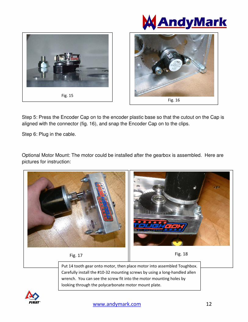
www.andymark.com 12
Step 5: Press the Encoder Cap on to the encoder plastic base so that the cutout on the Cap is
aligned with the connector (fig. 16), and snap the Encoder Cap on to the clips.
Step 6: Plug in the cable.
Optional Motor Mount: The motor could be installed after the gearbox is assembled. Here are
pictures for instruction:
Fig. 17
Fig. 18
Fig. 15
Fig. 16
Put 14 tooth gear onto motor, then place motor into assembled Toughbox.
Carefully install the #10-32 mounting screws by using a long-handled allen
wrench. You can see the screw fit into the motor mounting holes by
looking through the polycarbonate motor mount plate.

www.andymark.com 13
8. Battery Plug Usage
Four white plastic AndyMark battery plugs (am-0122) are included in the Drive
System kit.
These plugs are intended to be flags for charged batteries. They also serve as a
safety insulators for charged batteries.
Procedure for using these plugs:
1. Remove charged battery from charger
2. Insert white Battery Plug into the charged battery’s red Anderson
connector.
3. Place battery on shelf
a. As battery waits for it’s chance to power a robot, anyone who sees
that battery with the white plug will know it is a charged battery
4. Remove battery plug before installing battery on robot
5. Remove un-charged, spent battery from robot, but don’t put the white
battery plug back in (or someone will think that it is charged)
Un-charged
Battery without
battery plug
Battery being
charged
Charged Battery
with battery plug

www.andymark.com 14
9. Background on AndyMark
Andy Baker and Mark Koors have been FIRST mentors since 1998, serving
on FRC team 45, the TechnoKats. Before starting AndyMark, they worked as
engineers at Delphi Automotive Electronics in Kokomo, Indiana. In 2004, Andy
and Mark started AndyMark.
For a few years, Andy and Mark ran the company out of their homes while
they were still working as engineers at Delphi. In 2007, AndyMark moved into
the Inventrek technology park in Kokomo. Shortly afterward, both Andy and
Mark went to work full-time at AndyMark.
Andy and Mark serve as volunteers at many events within the FIRST
community. AndyMark sponsors three FIRST Robotics teams in the Kokomo
area (45, 292, 1760), and also is a sponsor of the Boilermaker Regional, the
Indiana Robotics Invitational (IRI) and the CAGE Match. Both Andy and Mark
are well-respected in the FIRST community: Andy won the Championship
Woodie Flowers Award in 2003, while Mark was recognized as the
Championship Volunteer of the Year in 2007. You can find Andy and Mark at
many FRC Regional events, and the Championships every year. Andy often
serves as an inspector or referee at events, while Mark is a prominent FTA for
many events.
AndyMark, Inc. has been a supplier to the FIRST Kit of Parts since 2005,
and has increased their donation to FIRST every year.
AndyMark, Inc. provides unique, high quality products for mobility robotics,
in a timely fashion. AndyMark is your robot parts experts. For more information
on AndyMark products, see the www.andymark.com and www.tektray.com
websites.
95% of all of AndyMark parts are fabricated and assembled in the USA.