2010 TDP_PE_VOL_I
92
i
-
Upload
giankarlaera9856 -
Category
Documents
-
view
894 -
download
14
Transcript of 2010 TDP_PE_VOL_I
i

1

2
2010
TRANSMISSION DEVELOPMENT PLAN Consultat ion Draft

i
DISCLAIMER
The Transmission Development Plan (TDP) is prepared and published solely for information purposes. While NGCP, to the best of its knowledge, has used the most accurate data available, and has used utmost prudence in the use of those information, nothing in this
document can be or should be taken as a recommendation in respect of any possible investment or business decision. This document does not claim to contain all the information that a prospective investor or grid user or potential participant to the electricity market, or any other person or interested parties may require for making decisions. In preparing this document it is not possible nor it is intended for NGCP to have considered the investment objectives, financial situation and particular needs of each person who uses this document.
In all cases, anyone proposing to rely on or use the information in this document should independently verify and check the accuracy,
completeness, reliability and suitability of that information and the reports and other information relied on by NGCP in preparing this document, and should obtain independent and specific advice from appropriate experts.
In the same manner, NGCP does not make representations or warranty as to the accuracy, reliability, completeness or suitability for particular purposes of the information in this document. Persons reading or using this document acknowledge that NGCP and/or its
employees shall have no liability (including liability to any person by reason of negligence or negligent misstatement) for any statements, opinions, information or matter (expressed or implied) arising out of, contained in or derived from, or for any omissions from, the
information in this document, except insofar as liability under any statute of the Republic of the Philippines cannot be excluded.

ii
Foreword Following its official takeover as the operator of the nationwide transmission system in January 2009, the NATIONAL GRID CORPORATION OF THE PHILIPPINES (NGCP) has gained the right momentum to implement programs that have produced substantial reliability and economic benefits to the stakeholders in the last two years.
Looking ahead, this 2010 Transmission Development Plan (TDP) report provides insights to the plans laid out by NGCP for 2010-2019. This ten-year plan is in response to the challenges resulting from increase in demand, new generation projects, need for reliable transmission network and support to efficient market operation – all of which are considered within the established technical and regulatory framework of the electric power industry.
For 2011-2015, the network expansion projects to be implemented by NGCP are those approved by the Energy Regulatory Commission (ERC) in the Final Determination for the Third Regulatory Period. Transmission investments associated with proposed generation projects would have to be filed separately with the ERC. NGCP may also line up expansion projects for residual sub-transmission assets that have been reverted back into the regulatory asset base.
Following the agreement with the Department of Energy (DOE), NGCP used its own load forecast and generation capacity addition in the preparation of 2010 TDP Volume I. The Power Development Program (PDP) Update, which DOE will release by last quarter of 2010, will be used for the 2011 TDP. This will enable more timely releases and synchronized NGCP’s conduct of transmission planning studies for the TDP vis-à-vis updating of DOE PDP.
To sustain NGCP’s transmission business operations, Volume II and III outline the ten year plan for operations and maintenance and system operations, respectively. More than just a statement of capital expenditure program for rehabilitation, replacement and maintenance of network facilities, volumes II and III will allow NGCP to cope with changes over the planning horizon, respond to the operational needs of its customers and adopt to the desired ‘end state’ of the transmission system as envisioned in the long-term plan.

iii

iv
Table of Contents
Chapter 01. Preliminaries ............................................................................................................ 1
1.1 About NGCP ..................................................................................................................... 1 1.1.1 Organization/Operation ............................................................................................ 1 1.1.2 NGCP as a Regulated Entity ..................................................................................... 2
1.2 Content Overview ........................................................................................................... 2
Chapter 02. Assessment of Transmission System ............................................................. 5
2.1 Grid Profile ........................................................................................................................ 5 2.1.1 Luzon ............................................................................................................................ 5 2.1.2 Visayas .......................................................................................................................... 6 2.1.3 Mindanao ..................................................................................................................... 6
2.2 Features of the Transmission System ......................................................................... 6 2.2.1 Luzon ............................................................................................................................ 6 2.2.2 Visayas .......................................................................................................................... 7 2.2.3 Mindanao ..................................................................................................................... 8
2.3 Problems and Issues ........................................................................................................ 8 2.3.1 Luzon ............................................................................................................................ 8 2.3.2 Visayas .......................................................................................................................... 9 2.3.3 Mindanao ................................................................................................................... 11
Chapter 03. Demand Projections andCapacity Additions ............................................ 13
3.1 Second Regulatory Period Final Determination on Demand Forecasts .......... 13 3.2 TDP Power Demand Projection ................................................................................ 13
3.2.1 Demand Projections for Substation Capacity Addition ...................................... 16 3.2.2 Demand Projectionsfor Transmission Expansions................................................ 17
3.3 Generation Capacity Addition .................................................................................... 17 3.3.1 Supply Expansion Plan ............................................................................................. 17 3.3.2 Generation Proponents ............................................................................................ 17
3.4 Supply-Demand Outlook .............................................................................................. 19 3.4.1 Luzon .......................................................................................................................... 19 3.4.2 Visayas ........................................................................................................................ 20 3.4.3 Mindanao ................................................................................................................... 21
Chapter 04. Recently Completed Projects.......................................................................... 23
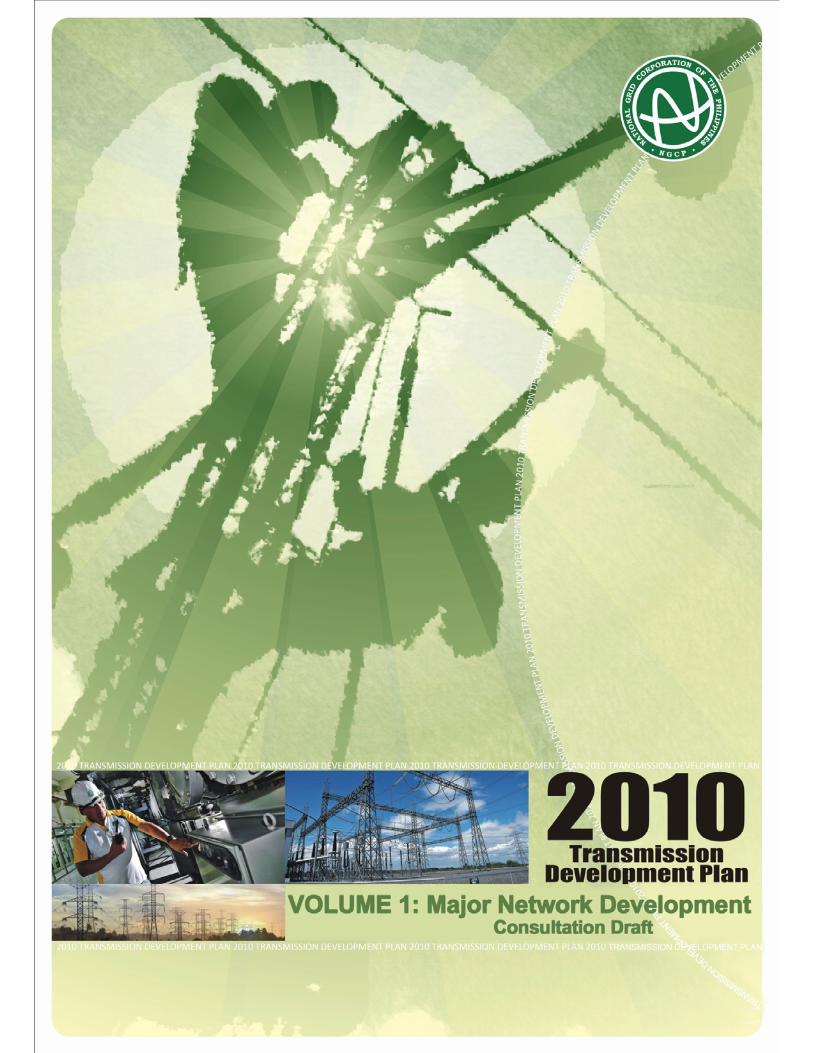
4.1 San Jose Transformer Replacement .......................................................................... 23 4.2 Maramag – Bunawan 230 kV Transmission Line .................................................... 23 4.3 Visayas Capacitor Project 1 ....................................................................................... 24
Chapter 05. Ongoing Projects .................................................................................................. 25
5.1 Non-Network Projects ................................................................................................ 25 5.1.1 Hermosa-Quezon 230kV Transmission Line Relocation ...................................... 25
5.2 Generation-Associated Projects ................................................................................ 26 5.2.1 Mariveles Coal Transmission Reinforcement ........................................................ 26

v
5.2.2 New Naga Substation .............................................................................................. 26 5.3 Load Growth-Driven Projects .................................................................................... 28
5.3.1 Luzon .......................................................................................................................... 28 5.3.1.1 Dasmariñas Substation Expansion ...................................................................... 28 5.3.1.2 Dasmariñas-Rosario 115 kV Transmission Line .................................................. 29 5.3.1.3 Luzon Substation Expansion 1 ........................................................................... 29
5.3.2 Visayas ........................................................................................................................ 30 5.3.2.1 Bohol Backbone Transmission Project ................................................................. 30 5.3.2.2 Negros V Transmission Line ............................................................................... 31 5.3.2.3 Negros-Panay Interconnection Uprating (Phase 1) ............................................... 31 5.3.2.4 Northern Panay Backbone Transmission ............................................................. 32 5.3.2.5 Paranas-Carayman Transmission Line ................................................................. 32 5.3.2.6 Southern Panay Backbone Transmission ............................................................. 33
5.3.3 Mindanao .................................................................................................................. 34 5.3.3.1 Aurora-Polanco 138 kV Transmission Line .......................................................... 34 5.3.3.2 Balo-i-Villanueva 230 kV Transmission Line ....................................................... 34 5.3.3.3 Mindanao Substation Expansion-2005 ............................................................... 35 5.3.3.4 Sangali-Zamboanga 138 kV Transmission Line ................................................... 35
5.4 Congestion ....................................................................................................................... 36 5.4.1 Biñan-Muntinlupa Transmission Line Upgrade .................................................... 36
5.5 Reliability and Power Quality Projects ..................................................................... 37 5.5.1 Luzon .......................................................................................................................... 37
5.5.1.1 Binga-San Manuel 230 kV Transmission Line .................................................... 37 5.5.1.2 Luzon Power Circuit Breaker Replacement.......................................................... 38 5.5.1.3 Luzon Transmission Equipment Upgrade ............................................................ 38
5.5.2 Visayas ........................................................................................................................ 39 5.5.2.1 Visayas Power Circuit Breaker Replacement ........................................................ 39
5.5.3 Mindanao ................................................................................................................... 40 5.5.3.1 Gen. Santos-Tacurong 138 kV Transmission Line ................................................ 40 5.5.3.2 Mindanao Power Circuit Breaker Replacement ................................................... 40 5.5.3.3 Mindanao Shunt Reactors and Capacitors .......................................................... 41 5.5.3.4 Sultan Kudarat and Nabunturan Substation Expansion ....................................... 41 5.5.3.5 Villanueva-Maramag 230 kV Transmission Line .................................................. 42
Chapter 06.Projects for 2011-2015 ......................................................................................... 43
6.1 Generation-Associated Projects ................................................................................ 43 6.1.1 Kalayaan-Bay 230 kV Line Upgrading .................................................................... 43 6.1.2 Tayabas Substation Expansion 1 ............................................................................ 45 6.1.3 Calung-calung-Toledo-New Naga 138 kV Transmission Line ............................. 45
6.2 Load Growth-Driven Projects .................................................................................... 46 6.2.1 Luzon .......................................................................................................................... 46
6.2.1.1 Luzon Substation Expansion II ............................................................................ 46 6.2.1.2 Luzon Substation Expansion III ........................................................................... 47 6.2.1.3 Luzon Substation Expansion IV .......................................................................... 47 6.2.1.4 New Antipolo 230 kV Substation........................................................................ 48
6.2.2 Visayas ........................................................................................................................ 49 6.2.2.1 New Naga-Cebu Transmission Line .................................................................... 49 6.2.2.2 Visayas Substation Expansion I ........................................................................... 50
6.2.3 Mindanao ................................................................................................................... 50 6.2.3.1 Mindanao Substation Expansion 2 ..................................................................... 50

vi
6.3 Congestion ...................................................................................................................... 51 6.3.1 Ambuklao-Binga 230 kV T/L Upgrading ................................................................ 51 6.3.2 San Jose-Quezon Line 3............................................................................................ 52
6.4 Reliability And Power Quality Projects .................................................................. 53 6.4.1 Luzon .......................................................................................................................... 53
6.4.1.1 Dasmariñas EHV Substation Expansion .............................................................. 53 6.4.1.2 Eastern Albay 69 kV Line ................................................................................... 54 6.4.1.3 Luzon Substation Reliability I .............................................................................. 54 6.4.1.4 Luzon Voltage Improvement I ............................................................................ 55 6.4.1.4 Luzon Voltage Improvement II ........................................................................... 55 6.4.1.5 Magapit Capacitor ............................................................................................. 56 6.4.1.6 San Jose-Angat 115 kV Line Upgrading .............................................................. 56 6.4.1.7 San Esteban- Laoag 230 kV Transmission Line .................................................. 57 6.4.1.8 Santiago-Tuguegarao 230 kV Line 2 .................................................................. 58
6.4.2 Visayas ........................................................................................................................ 59 6.4.2.1 Cebu-Mandaue-Lapu-Lapu Transmission Line ..................................................... 59 6.4.2.2 Culasi-Sibalom 69 kV Transmission Line ................................................................ 60 6.4.2.3 Ormoc-Babatngon Transmission Line .................................................................... 60 6.4.2.4 Ormoc-Maasin Transmission Line ......................................................................... 61 6.4.2.5 Sta.Rita-Quinapundan 69 kV Transmission Line .................................................. 62 6.4.2.6 Visayas Substation Reliability I .............................................................................. 62 6.4.2.7 Visayas Substation Reliability II ............................................................................. 63
6.4.3Mindanao ..................................................................................................................... 64 6.4.3.1 Agus 6-Aurora 138 kV Transmission Line .............................................................. 64 6.4.3.2 Butuan-Placer 138 kV Transmission Line ............................................................ 64 6.4.3.3 Maramag-Kibawe 138 kV Transmission Line ...................................................... 65 6.4.3.4 Matanao-Gen. Santos 138 kV Transmission Line ................................................ 66 6.4.3.5 Mindanao Substation Reliability I .......................................................................... 65 6.4.3.6 Tacurong-Sultan Kudarat 138 kV Transmission Line ........................................... 66
CHAPTER 07. PROJECTS BEYOND 2015 (INDICATIVEPROJECTS)................... 67
7.1 Generation Association Projects ................................................................................ 67 7.2 Load Growth-Driven Projects ..................................................................................... 67 7.3 Reliability and Power Quality Projects ..................................................................... 68 7.4 Island Interconnection Projects .................................................................................. 68
7.4.1 Visayas ........................................................................................................................ 68 7.4.2 Luzon-Mindoro .......................................................................................................... 69 7.4.3 Leyte-Mindanao ........................................................................................................ 69
CHAPTER 08. RESIDUAL SUB-TRANSMISSION ASSETS ........................................ 71
8.1 Luzon ............................................................................................................................... 71 8.2 Visayas ............................................................................................................................. 72 8.3 Mindanao ......................................................................................................................... 73

vii
Chapter 09. Appendices .............................................................................................................. 75
Appendix 1– List of Official Site Names of Substations based on the Standard System of Site & Equipment Identification and Labeling(SEIL)- Rev. 1 ............................................................................................................ 75
A1.1 Luzon ................................................................................................................. 75 A1.2 Visayas ............................................................................................................... 76 A1.3 Mindanao ......................................................................................................... 76
Appendix 2 – Grid Code Performance Standard ......................................................... 77 A2.1 Voltage Variation ............................................................................................. 77 A2.2 System Loss Standard ...................................................................................... 78 A2.3 Performance Indices ........................................................................................ 78
Appendix 3 – Other Projects ............................................................................................ 79 A3.1 Aglipay-Casiguran 69 kV Line ........................................................................ 79 A3.2 Tacurong-Kalamansig 69 kV Line .................................................................. 79
Appendix 4 – Existing Island Interconnections ............................................................. 80 Appendix 5 – Contact Details ........................................................................................... 81

1
Chapter 01. Preliminaries 1.1 About NGCP
1.1.1 Organization/Operation NGCP’s functions as the Transmission Service Provider involve the transmission of electricity in response to system and market demands:
1. From generator connection points to distribution network connection points and the direct connection points of a number of large end-users.
2. Between the three major regions of the Philippines, namely: Luzon, Visayas and Mindanao, thereby increasing reliability and reducing the overall cost of generation nationally.
In order to undertake the above services, NGCP operates a substantial control and delivery network, the key elements of which include:
1. High-voltage transmission network including submarine cable, equipped with protection system;
2. The Supervisory Control and Data Acquisition system (SCADA); 3. Regional control centers; 4. Numerous substations and depots, each of which are linked back to the central
system; 5. Converter stations (HVAC - HVDC); and 6. A comprehensive metering system at substations, and direct customer delivery
points. For business management purposes, NGCP’s obligations can be grouped into six (6) key service areas described as follows:
1. System operations: managing the national power grid, dispatching generation and managing the system, including the arrangement for ancillary services.
2. Network reliability: providing the appropriate levels of network reliability in accordance with the reliability requirements set forth in the Grid Code.
3. Connection service: NGCP’s obligations, primarily to customers and prospective customers (e.g. generators, distributors and large end users) to provide effective, timely and efficient connection services, including metering and relevant services.
4. Safety: NGCP’s obligations, primarily to its stakeholders (e.g. staff, other electricity industry employees and the community) to deliver its services with appropriate priority given to human safety.
5. Environmental: NGCP’s obligations, primarily to its stakeholders (e.g. the community and government) to deliver services in an environmentally responsible manner.
6. Wholesale Electricity Market: NGCP’s obligations in relation to the operation and development of the electricity market, by way of the provision of efficient and effective transmission services.
In addition, NGCP continues to operate a significant set of sub-transmission services from high voltage delivery points to end users. These sub-transmission assets have been offered for sale to the distribution utilities in compliance with the requirement of the Republic Act No. 9136 (Electric Power Industry Reform Act of 2001), or EPIRA.
Pursuant to ERC Resolution No. 18 series of 2009, those sub-transmission assets which have not been sold or disposed of by 31 December 2010 shall remain as NGCP’s assets which shall be included into the regulatory asset base.

2
1.1.2 NGCP as a Regulated Entity With the enactment of the EPIRA, generation, transmission, distribution and supply are distinguished as different business activities within the Philippine electricity industry. Among these activities, transmission and distribution exhibit natural monopoly characteristics which make regulation on them appropriate. Generation and retail sale of electricity, on the other hand, can be efficient in the competitive environment as a result of the reforms introduced by the EPIRA.
As the sole transmission service provider, NGCP is regulated under the performance-based ratemaking (PBR). The PBR is a form of utility regulation that strengthens the financial incentives to lower rates or lower costs. The PBR methodology is outlined in the Rules for Setting Transmission Wheeling Rates or RTWR.
1.2 Content Overview The 2010 TDP consists of three (3) volumes. This Volume I contains the proposed grid expansion and upgrades, which generally, are the results of system studies. The other volumes outline the capital expenditure programs of Operation and Maintenance (Volume II) and System Operations (Volume III-Part 1). Those for metering services have been integrated into Volume III but in a separate report (Volume III-Part 2). Volume I consists of nine (9) chapters. Chapter 1 provides an overview of NGCP’s organization and operation as transmission service
provider and regulated entity. Chapter 2 explains the assessments made on the existing transmission network, gives insights
on the profile of eachgrid and identifies the existing and potential problems/constraints/issues in the system.
Chapter 3 discusses the latest demand projections and generation capacity addition used by NGCP as input to the simulation studies to identify future transmission constraints and transmission expansion associated with load growth, new generation connections and reliability requirements. Also included in this chapter is the supply-demand outlook of each grid for the planning horizon.
The next five chapters discuss how the projects are classified, the summary of which are shown in Table 1.1. Chapter 4 enumerates the projects that have been completed from 01 January 2009 to 31
October 2010. Chapter 5 describes NGCP’s ongoing projects in the Luzon, Visayas and Mindanao grids. Chapter 6 identifies the projects that are needed to be completed for the period 2011-2015. Chapter 7 provides the list of projects beyond 2015 (indicative projects). Chapter 8 provides an overview of the status of residual sub-transmission assets in each grid. Chapter 9 contains different appendices that contain discussions on relevant topics such as the
Grid Code performance standards, and other projects requested by some sectors.

3
Table 1.1 2010 TDP Project Classification
CLASSIFICATION WITH
REGULATORYAPPROVAL?
DESCRIPTION
1. Recently Completed Projects
Yes Completed between 01 January 2009 to 30 November 2010
2. Ongoing Projects Yes Construction activities are underway
3. Projects in the Third Regulatory Period
(2011-2015)
(Awaiting Final Determination)
Projects to be implemented in the Third Regulatory Period and grouped into generation-associated, load growth-driven, congestion, and
reliability/power quality projects
4. Indicative Projects To be filed for approval Projects with need dates between 2016-2019
5. Residual Sub-transmission Assets
(RSTA) To be filed for approval Proposed upgrading/expansion of RSTA
(in case not divested by end of 2010)
There are also projects requested by some sectors that have been and/or will be filed to the ERC. These projects are listed in Appendix 3.

4

5
Chapter 02. Assessment of Transmission System
2.1 Grid Profile As of 31 December 2009, NGCP’s managed transmission assets comprised of 19,425 circuit kilometers (ckt-km). About half of these assets, or 9,568 ckt-km are in Luzon. 4,600 ckt-km form part of the Visayas Grid and the remaining 5,257 ckt-km are in Mindanao. Roughly 77% (18,452 MVA) of the total 23,873 MVA substation capacities installed are in Luzon. The Visayas account for 3,161 MVA and Mindanao 2,260 MVA. These figures exclude transmission lines and transformer assets which had been decommissioned already.
Table 2.1 Summary of Existing Facilities SUBSTATION CAPACITY (IN MVA)
2009 2008 2007 2006 2005 PHILIPPINES 23,873 24,214 24,732 24,489 24,607
Luzon 18,452 18,861 19,411 19,121 19,236 Visayas 3,161 3,154 3,171 3,268 3,371
Mindanao 2,260 2,200 2,150 2,100 2,000
TRANSMISSION LINE LENGTH (IN CKT-KM)
2009 2008 2007 2006 2005* PHILIPPINES 19,425 19,778 20,129 20,236 20,236
Luzon 9,568 9,527 9,712 9,840 9,881 Visayas 4,600 4,745 4,856 4,845 4,807
Mindanao 5,257 5,506 5,561 5,552 5,547 * Note:Although there were newly-constructed and operational lines in 2008, there was a decrease in total transmission line length in
ckt-km due to modification and divestment of various sub-transmission assets.
To ensure that voltages across the network are within the levels prescribed in the Philippine Grid Code (the “Grid Code”), capacitors and reactors have been installed in appropriate locations in the different parts of the region. Currently, there are a total of 1,081.45 MVAR capacitors distributed as follows: 600 MVAR in Luzon, 226.45 MVAR in the Visayas, and 255 MVAR in Mindanao. These exclude the capacitors at the Naga converter station, which provides the MVAR requirements thereat. The total reactors are 620 MVAR for Luzon and 555 MVAR for Visayas, or a total of 1,175 MVAR. A new 90 MVAR reactor has been installed at the Bolo Substation in Labrador, Pangasinan to prevent the occurrence of high system voltage in northern Luzon. The dependable capacity indicated in the following sections is based on the 2009 Power Sector Situationer of the DOE. The DOE defines dependable capacity as the maximum capacity a power plant can sustain over a specified period modified for seasonal limitation less the capacity required for station service and auxiliaries.
2.1.1 Luzon In 2009, Luzon has reached its peak demand for the year at 6,928 MW, which is 254 MW or 3.80% higher than in 2008. Historically, the peak load in the island occurred during the first semester. Meralco accounts for about 70% of this demand. From 2001-2009, Luzon exhibited 2.70% annual average compounded growth rate (AACGR).
As of end of 2009, Luzon grid has a total dependable capacity of 10,230 MW. A total of 5,379 MW (53%) are located in the south while the remaining 4,851 MW (47%) are in the north. More than half of the capacity are coal-fired (3,450 MW or 34%) and natural gas (2,700 MW, 26%). Hydro accounts for a fifth (1,999 MW, 20%) while diesel and geothermal have dependable capacity of 1,617 MW (16%) and 431 MW (4%), respectively. The existing wind farm (Northwind) in Luzon grid, on the other hand, has rated capacity of 33 MW.

6
2.1.2 Visayas At 5.82% growth rate, Visayas has posted the highest AACGR among the three grids in 2001-2009. In 2009, the peak load was recorded at 1,241 MW (based on coincident peak), 65 MW or 5.52% higher than in 2008.
As of end of 2009, the Visayas grid has a total dependable capacity of 1,392 MW, more than half (792 MW or 57%) of which comes from the geothermal fields in Leyte. The Visayas islands remain highly dependent on diesel and oil as more than a third of the capacity is supplied by diesel (426 MW, 31%); coal accounts for about 11% (153 MW) while hydro has about 13 MW dependable capacity. 2.1.3 Mindanao Mindanao experienced an increase in system peak demand in 2009 with 1,303 MW or 8.27% higher than in 2008. From 2001-2009, the island registered a 3.71% AACGR.
As of end of 2009, the Mindanao grid has a total dependable capacity of 1,697 MW, 902 MW of which, or about 53%, comes from hydro resources, particularly the Agus complex in Lanao;diesel accounts for 29% (485 MW), coal contributes210 MW (12%) and geothermal, 98 MW (6%).
2.2 Features of the Transmission System
2.2.1 Luzon In Luzon Grid, the bulk generation sources are located in the northern and southern parts of the Luzon Island while the load center is in Metro Manila which accounts for about 70% of the total Luzon load. Because of this system configuration, the transmission backbone must have capability to transfer large amount of power from both the north and south.
2.2.1.1 The Northern Transmission Corridor The northern transmission corridor consists of several flow paths for transferring power from the sites located in the north to Metro Manila. The main path is the 500 kV double-circuit transmission line from Bolo to Nagsaag then to San Jose. The other paths are the three underlying 230 kV transmission lines consisting of the Labrador to Hermosa single circuit line, the recently upgraded San Manuel-Concepcion-Mexico double circuit line, and the San Manuel-Pantabangan-Cabanatuan-Mexico single-circuit line.
The Bolo and Nagsaag EHV substations are the receiving ends of generation from the north. The received power is then delivered to Metro Manila mainly via Mexico and San Jose substations. The 500 kV Bolo-Nagsaag-San Jose is rated at 2,850 MVA per circuit and is capable of transferring the more than 1,800 MW generation from Masinloc and Sual Coal Plants to Metro Manila. The upgraded San Manuel-Concepcion-Mexico 230 kV Line, on the other hand, is an alternate corridor which also caters the generation capacity of the hydroelectric plants delivering power to San Manuel 230 kV substation. 2.2.1.2 The Southern Transmission Corridor The southern transmission corridor also consists of 500 kV transmission backbone and underlying 230 kV transmission lines. The southern portion of the 500 kV transmission backbone stretches from Naga in Bicol area to Tayabas, Quezon. This 500 kV backbone segment, however, is currently energized at 230 kV voltage level. The Naga substation is also the termination point for the HVDC system that could allow the exchange of up to 440 MW of power between Luzon and Visayas grids.
From Tayabas, the 500 kV backbone also stretches to Dasmariñas substation which serves as a drawdown substation for the loads in the south of Metro Manila.

7
Tayabas is also connected to San Jose thereby completing the link between the north and south 500 kV corridors.
The 500 kV backbone in the south facilitates the transfer of about 2,400 MW of power from Ilijan Natural Gas, Pagbilao and QPPL coal plants. The 230 kV transmission system in Batangas and Laguna area, on the other hand, caters about 2,100 MW total generation capacity of Calaca Coal and the other Natural Gas Plants (Sta. Lorenzo and Sta. Rita). 2.2.1.3 The Metro Manila Transmission Configuration In Metro Manila, the major 230 kV substations are Quezon, Taytay, Doña Imelda, Muntinlupa, Las Piñas and Marilao (Meralco-owned). Four (4) of these substations (Taytay, Quezon, Doña Imelda and Muntinlupa) form part of the 230 kV ring that surrounds the Laguna Lake. The Quezon-Doña Imelda-Muntinlupa segment of the ring, however, is a single-circuit line traversing within Metro Manila.
At present, there are two (2) main load sectors within Metro Manila. Sector 1 consists of Quezon, Doña Imelda and Marilao while Sector 2 consists of Taytay, Muntinlupa and Las Piñas 230 kV substations. The 115 kV distribution facilities in each sector are looped and therefore can be supplied alternately from different 230 kV substations during contingency. Upon completion of Meralco’s Paco 230 kV substation (cut-in along Doña Imelda-Muntinlupa line) by 2011, Meralco will reconfigure the 115 kV network into three (3) sectors. Marilao, Quezon and Paco will be under Sector 1, Doña Imelda and Taytay under Sector 2 while Muntinlupa and Las Piñas under Sector 3.
The major supply lines for both Quezon and Taytay are the double-circuit facilities from San Jose. As no major power plants are in place in the 230 kV system near the northern side of Metro Manila, these substations rely heavily on the supply from San Jose 500 kV substation. With NGCP’s recent completion of the San Jose Transformer Replacement Project, the reliability of this critical San Jose substation was significantly increased.
In the south, the power requirements are being drawn from Dasmariñas EHV substation and from the plants directly connected to the 230 kV system. Las Piñas is being supplied by a double circuit 230 kV radial line from Dasmariñas while Muntinlupa has four-circuit supply line from Biñan.
2.2.2 Visayas The Visayas transmission system can be divided into four different sub-system or sub-grids.
First is the Eastern Visayas Area (District 1), which is composed of the islands of Leyte and Samar. Leyte is the site of 610 MW geothermal resources that comprise the 42% of the total generation capacity in the Visayas. It has two transmission corridors which separately serve Samar and Bohol, both of which rely on power generated by Leyte’s steam fields.
Second is the Central Visayas Area (District 2), which is composed of the islands of Cebu and Bohol. Cebu can be well considered as the load center of the Visayas grid. In 2009, it has a coincident peak load of 559 MW which accounted for 45% of the grid’s total demand. Bohol, on the other hand, had the lowest peak load for the grid with 56 MW (4.5%).
Third is the island of Negros (District 3). The load center is located in Bacolod City in the northern part, while the bulk of generation is in the southern part. The 10 MW Northern Negros Geothermal Plant provides the only source of voltage regulation in the north.
Finally, the Western Visayas Area (District 4) is the Panay island. The likely entry of the 164 MW PEDC coal-fired plant in La Paz, Iloilo will provide the island sufficient generation capacity up to at least year 2025, assuming that the diesel plants will not be retired.

8
The sub-grids are interconnected by submarine cables: Leyte-Cebu (2x185 MW), Cebu-Negros (2x90 MW), Negros-Panay (1X85 MW) and Leyte-Bohol (1x90 MW). The capacities indicated are the nominal rating of the interconnections.
Taking into consideration the load flow from east to west (or vice versa) of the Visayas grid, the transmission backbone of the Visayas grid extends from the far east, at the Allen CTS in Samar, all the way to Nabas substation in Panay, in the far west. This route is comprised of approximately 895 kilometers of transmission line. It is composed of the HVDC line, overhead transmission lines and submarine cables.
The bulk generation in Visayas, which is sourced from Leyte steam fields, is transmitted to the other islands through the following transmission corridors:
1. Leyte-Samar transmission corridor, which is composed of the Ormoc-Babatngon and Babatngon-Paranas 138 kV lines. The former is a single circuit line while the latter is a double circuit line;
2. Leyte-Bohol transmission corridor, which is composed of the following 138 kV lines: (i) Ormoc-Maasin-Guadalupe; (ii) the Guadalupe-C.P. Garcia submarine cable (Leyte-Bohol interconnection); and (iii) C.P. Garcia-Ubay. All of these lines, including the submarine cable, are single-circuit only; and
3. Leyte-Cebu-Negros-Panay transmission corridor, which is the longest corridor. This corridor, which has transmission lines energized at 230 kV, is considered as the main transmission backbone since it allows the supply of power to the load center of the different sub-grids.
2.2.3 Mindanao The 663MW(dependable capacity based on DOE data) Agus Hydro Complex located in Lanao accounts for about 39% of Mindanao’s total dependable capacity. Much of the generated output of the complex must be transmitted to the load centers located in southern part of the island. The load centers are located in southeast (Davao provinces) and southwest (SOCCSKSARGEN). As of end of 2009, these two areas account for about 50% of the island’s total demand: Davao area, 464 MW (35%) and SOCCSKSARGEN, 199 MW (15%).
Given this characteristic and considering the 225 MW Pulangi hydro plant located in north central area, the load flow generally is from north to south. Much of the power flow passes through Balo-i-Tagoloan-Maramag-Kibawe 138 kV corridor. This is being reinforced by the ongoing Balo-i-Villanueva-Maramag-Bunawan backbone that is designed at 230 kV, the Maramag-Bunawan segment of which was energized in October 2010.
2.3 Problems and Issues
2.3.1 Luzon As the center of commerce and trade, the demand within Metro Manila continues to grow thus necessitating the expansion of existing substations and building of new ones. Although this has been expected, NGCP faces big challenge in responding to these needs primarily due to space limitations of the 230 kV substations within the Metro and the problem in acquiring right-of-way for the new transmission lines and substations. As a common problem in an urbanized area, acquiring right-of-way for new transmission lines and area for new substations would be difficult. Moreover, the capital region is geographically unique as the land area between the Manila Bay and Laguna Lake is rather narrow (with about 10 km width only).
Developing power generating power plants within Metro Manila is actually ideal in order to reduce power imports. However, the environmental concerns, area congestion, and high cost of realty would make the implementation difficult.
The completion of the San Jose Transformer Replacement Project has provided the much-needed relief to the congestion that was experienced at San Jose Substation. Being the

9
merging point of bulk power coming from the north and the south, San Jose has been a critical substation.
The Kalayaan-Bay corridor is another 230 kV line project in south Luzon that is intended to allow all possible generation dispatch scenarios for the associated power plants. The proposed configuration is a double circuit line that would increase the transfer capability from 300 MVA to 1200 MVA and the Calauan substation will be radially connected to Kalayaan. This has been tagged as high-priority project which will solve existing bottleneck problems and will further enhance reliability.
The transmission facilities serving the north-eastern and north-western regions of Luzon Island have no provisions for N-1 contingency. In the north-western side, the reinforcement of the facilities would be required to provide a strong connection point for the in-coming wind farm power plants in the area. In the north-eastern side, reinforcing the long single-circuit transmission line in Isabela and Cagayan is also necessary to reliably serve the increasing demand in the region. Also, to support the rich wind power generation potential of northern Luzon and to increase reliability, the implementation of the previously conceptualized 230 kV transmission loop to link together the north-eastern and the north-western backbone is being studiedfurther.
Moreover, there are generation expansion projects that will require the upgrading or reinforcement of the dedicated lines for the power plants. These include the upgrading of Magat-Santiago and QPPL-Tayabas 230 kV lines in order to provide N-1 during maximum dispatch of Magat HEP and QPPL Coal Plant, respectively. The required upgrading projects, however, have not been lined up in the TDP since these will be undertaken by the generator proponents consistent with the existing policy of the ERC. 2.3.2 Visayas The Visayas Grid has been in critical power situation the past years. This has been aggravated because the consumers use more air-conditioning units due to intense heat from the dry and hot weather caused by the El Niño phenomenon, which resulted in the increase in demand in each of the Visayas sub-grid. Ideally, this must be met with corresponding installation of additional capacity within the island, otherwise the upgrade of existing submarine cables may be considered an option. The Visayas grid, however, cannot rely entirely on the submarine linkages to source power from one island to the other. Economics, higher system losses and voltage support requirements are important considerations in deciding which option to take. In many respect, distributed generation in the islands can better address these issues. NGCP is keenly monitoring the generation development in the islands to ensure that the network will be adequate to support new generation.
Additional transformers have been proposed for the Third Regulatory Period to provide redundancy to a number of substations and also to avert overloading during N-1. These transformers are grouped into Substation Expansion Project I, Substation Reliability Project I and Substation Reliability Project II. The first one, which is for load growth, should be completed in 2011 while the other two, which are for reliability, are scheduled to be completed in 2013 and 2014, respectively. It should be noted that most of those transformers for N-1 have been identified in the previous plans but were not implemented by TransCo due to capex limitation.
Construction of additional circuits is proposed forthe major transmission line corridors in Leyte, Cebu and Negros to comply with the N-1 requirement. As theload center, the major backbone in Cebu may need to be upgraded to 230 kV in the long term.
The lack of local generation within the islands has caused low voltage problems in many areas. The low voltage problem is very evident particularly in Negros and Panay.
The following discussions will provide an overview of the existing and potential problems and issues in each of the sub-grid:

10
2.3.2.1 Leyte-Samar The outage of the single circuit Ormoc-Babatngon 138 kV line, which is the main corridor for the supply of power to Samar, will cause power outage in the island. On the other hand, the outage of the Ormoc-Maasin 138 kV line will result to power outage in Maasin substation, thus also cutting the power flow to Bohol coming from Leyte. This will result in Bohol relying on its own inland generating power plants which are not sufficient to serve the total demand of the island. The same will be experienced in Bohol, as unavailability of Maasin-Guadalupe line will result in power outage in the island. In order to prevent this and also to comply with the N-1 requirement, the Ormoc-Maasin-Guadalupe has to be expanded to a double-circuit line. 2.3.2.2 Bohol Unless new generating facilities are installed in the island, Bohol will continue to rely heavily on Leyte for its power requirements. The island has few inland generating plants - Bohol diesel, Janopol hydro and Loboc hydro - the combined 23 MW capacity of which is not sufficient to supply the entire demand in the island. For this reason, the outage of the Leyte-Bohol interconnection will result in huge power interruptions in Bohol. For the interconnection with Leyte, initial results of the studies indicate that a second submarine cable must be in place by 2018, assuming that no new generators will be installed in Bohol.
The ongoing Bohol Backbone Project (Ubay-Corella 138 kV line) will provide the island a reliable transmission backbone. At present, the island relies on single circuit 69 kV woodpole backbone. 2.3.2.3 Cebu Cebu has almost half of the proposed capacity addition for the Visayas grid for 2010-2015. Two generators, 2x82 MW CEDC coal-fired, are already commissioned on the first half of 2010. The other generators that are expected to come-in are the CEDC’s other unit with the same capacity which is expected to be operational by end of 2010 and KEPCO’s 2x100 MW coal-fired in Naga. These power plants will necessitate the expansion of New Naga-Cebu 138 kV transmission line in order to accommodate the power flow from these new plants to the load centers in Cebu, which are the Cebu, Mandaue and Lapu-lapu substations. The Calung-calung-Toledo-New Naga 138 kV corridor must also be reinforced due to the entry of the CEDC plant.
Theoperation of 2-50 MVAR reactors in Daan-bantayan substation have been adjusted: one is permanent while the other one is put to operation only during off-peak hours to resolve overvoltage. This setup increases the power flow from Leyte to Cebu to 400 MW from the previous 360 MW when the reactors are continuously on-line. 2.3.2.4 Negros In Negros, the overhead lines that are linked to the Cebu-Negros submarine cable must be upgraded by installing additional 1-795 MCM circuit, otherwise the lines will be overloaded by 2011 during N-1 assuming that there is minimum generation in Panay. This corridor consists of the Amlan-Mabinay, Mabinay-Kabankalan and Kabankalan-Bacolod 138 kV lines.
Low voltage problems are being experienced in northern Negros, particularly in Bacolod which is the load center,due to the lack of inland generating plants, and the generators are located in the southern part far from the load center. Although this is the condition, the low voltage problem has already been remedied temporarily by disconnecting the 30 MVAR line reactor in Bacolod Substation.

11
2.3.2.5 Panay Although a number of diesel plants and power barges are located in the island, they are all peaking plants and therefore cannot provide the base load requirements. The Pinamucan Diesel which was transferred from Luzon in order to address the generation deficiency has a de-rated capacity.
The likely entry of the 164 MW PEDC coal-fired plant in La Paz, Iloilo will provide the island sufficient generation capacity up to at least 2018, assuming that the diesel plants will not be retired.
The complete 138 kV looping of the Panay grid can be considered in the long term. The two ongoing projects – Northern Panay Backbone (Panitan-Nabas) and Southern Panay Backbone (Sta. Barbara-San Jose) - have paved the way for this looping to happen. At the western side, the proposed Culasi-Sibalom 69 kV transmission line has been approved already by the ERC.
2.3.3 Mindanao Starting early 2010, Mindanao experienced a severe drought which had a tremendous impact on the electricity situation in the grid because the island relies mainly on hydropower. The El Niño phenomenon significantly reduced the dependable capacity of the hydro plants to a level even lower than the dependable capacity of oil-fired plants in the island.
Currently, the main corridors connecting the Agus complex to the grid are the Agus 2-Kibawe and Balo-i-Tagoloan 138 kV lines. The tripping of the Agus 2-Kibawe line in the past due to bombing incidents had resulted in huge power swing to the other corridors, one of which is the Maramag-Kibawe line, resulting in N-1 loading violation.
The ongoing Balo-i-Villanueva-Maramag-Bunawan transmission line projects will address this problem. With this 230 kV-designed corridor, which extends from the Agus hydro complex in the north to the Bunawan substation in the southeast, the huge hydro capacity of Agus (about 38% of the total grid) will have a reliable backbone to allow the delivery of its output to the major load centers located in southern Mindanao (about half of the island’s total demand).
Security problem, as what has been experienced in the bombing of Agus 2-Kibawe and other installations, remains a serious concern. There were also foiled attempts of bombings in key facilities. Implementation of projects, as in the case of the Tacurong-Sultan Kudarat 138 kV transmission line, cannot be pursued due to security threats. Mindanao has part of its network requiring provision for N-1, but some are being addressed by ongoing and projects to be implemented. Additional transformers, with a total of about 325 MVA, under the Substation Reliability Project I, are proposed for the Third Regulatory Period to provide redundancy to a number of substations and also to avert overloading during N-1. Additional transformers will be proposed in the next regulatory period.
Another weak point is the single circuit line in the eastern corridor. Although looped, the approximately 300 km single circuit line from Butuan to Nabunturan may need to be reinforced. Ongoing studies are being conducted to determine the appropriate timing for such upgrading.
The remaining old 138 kV woodpole backbone will be replaced by steel tower, double circuit line. The ongoing Gen. Santos-Tacurong Transmission Reinforcement Project will accomplish this. Aside from replacing the old dilapidated old structures, the reinforcement will prevent occurrence of low voltage problems in Tacurong and Gen. Santos in case of outage of Gen. Santos-Matanao line.
Basically, the main problem in Mindanao is generation deficiency. Unless new power plants come in, the grid will continue to experience power shortage especially on drought season. The government is currently looking for alternative sources of power and there are even suggestions to consider nuclear power. Big, new generation capacity in the island may also trigger the need for interconnection of Mindanao with the Visayas to ensure that excess capacity will find its market. This will also allow the Visayas grid to share any reserve and export power to Mindanao.

12

13
Chapter 03. Demand Projections andCapacity Additions
The two (2) important input parameters in the preparation of the TDP are the updated load forecast and generation capacity addition program. This section discusses these parameters used in the 2010 TDP. 3.1 Second Regulatory Period Final Determination on
Demand Forecasts In the 2nd Regulatory Period FD (Section 2.11.4), the ERC adopts the DOE forecast which intends to provide a signal to the investor that the demand forecast used came from an independent body. The demand forecasts adopted by the ERC are shown in Table 3.1.
Table 3.1 Demand Forecasts Adopted by the ERC for 2006-2010 GRID 2006 2007 2008 2009 2010 Luzon 6,728 6,981 7,252 7,552 7,878 Visayas 1,154 1,214 1,289 1,364 1,448
Mindanao 1,293 1,363 1,440 1,525 1,620 TOTAL 9,175 9,558 9,981 10,441 10,946
3.2 TDP Power Demand Projection The forecast for the 2010 TDP utilizes the latest demand projections of NGCP. The projections refer to the total electricity demand of the end-users including embedded generation and off-grid energy sources. NGCP prepares two sets of forecasts for the 2010 TDP: transmission-level (system peak demand or SPD) and substation capacity projections.
Basis of the transmission-level forecast NGCP undertakes forecasting exercise in coordination with power customers and the Department of Energy (DOE). NGCP forecasts the coincident peak demand (CPD) of each grid –Luzon, Visayas and Mindanao. The CPD is the sum of generators’ actual injection (measured every two seconds) into the grid. The System Peak Demand (SPD), on the other hand, is the CPD plus the demand associated with generation not injected into the grid (i.e., embedded generation). This addition to the CPD is based on the submission of embedded generators to the DOE. Hence, the SPD reflects the total (per grid) peak demand of a contiguous area/region – in this case, Luzon, Visayas and Mindanao. The SPD forecast of NGCP is comparable with the SPD forecast of DOE.
The CPD of a grid is forecasted by NGCP using econometrics – relating the peak demand with a number of economic and demographic explanatory variables. Explanatory variables range from national income (e.g., Gross Domestic Product or GDP), population and per capita income. In forecasting CPD, the national income (real GDP) is the main explanatory variable – hence, the projections are largely related with the forecasted movement of real GDP.
The Philippines experienced very modest GDP growth in 2009 at 0.9%. This may be attributed to the effects of the global financial crisis which strained demand for Philippine exports and tightened credit. However, strong signs of recovery in the Philippines have been observed in the first half of 2010 – GDP growth for the period is 7.9%. Further, robust consumption has been observed for the year coupled with the effects of fiscal stimulus initiated since last year. Additional economic activity has also been spurred by the election season. Due to the positive signs for the economy, the National Economic Development

14
Authority (NEDA) revised its year-end GDP forecast to 5%-6% from 2.6%-3.6%. International financial institutions also increased their GDP growth forecasts for the Philippines to reflect recent optimistic developments.
The spike in national income growth is also reflected in the CPD for 2010. For the first half of 2010, Luzon CPD grew by 10.5%, Visayas CPD by 13.2% and Mindanao by 1.6%. The suppressed generation of hydropower plants due to the El Niño phenomenon may have constrained growth of demand in Mindanao. However, with the onset of the La Niña phenomenon, this scenario may change for Mindanao in the latter half of the year as the grid’s peak usually occurs in November or December. Historical demand for electricity (2000-2009) The following shows the Peak Demand (MW) for the three grids (Luzon, Visayas, Mindanao) from 2000-2009. These values do not include demand from embedded generators that werenot synchronized with the grid. Luzon
The Luzon grid has posted an Average Annual Compounded Growth Rate (AACGR) of 2.70% for the period 2000-2009. Consistent steady growth has been recorded for the Luzon grid except for the decrease in demand observed in 2006. This is due to the reduction in the power consumption of Meralco during the year, whose demand accounts for at least 70% of the system peak demand. Visayas
The Visayas grid has posted an AACGR of 5.82% for 2000-2009, the highest among the three grids. This is largely due to the fast economic growth in the region. The fastest demand expansion has been recorded in distribution utilities in Panay, Cebu and Bohol.
5,450
5,646
5,823
6,149
6,323 6,479 6,466
6,643
6,674
6,928
5,000
5,250
5,500
5,750
6,000
6,250
6,500
6,750
7,000
7,250
7,500
2000 2001 2002 2003 2004 2005 2006 2007 2008 2009
Luzon Peak Demand (MW)
746
861 842
923 955 967
997
1,102
1,176
1,241
700
750
800
850
900
950
1,000
1,050
1,100
1,150
1,200
1,250
1,300
2000 2001 2002 2003 2004 2005 2006 2007 2008 2009
Visayas Peak Demand (MW)

15
Mindanao
The Mindanao grid has posted an AACGR of 3.80% for 2000-2009. After recording high annual growth rates from 2000 to 2004 (an average of 5.81%), demand growth has been sluggish from 2005 to 2008 (around 2.05%) due to the overall reduced power requirement from large non-utility customers.
TDP 2010 Projections Power demand for the country is expected to grow at an average compounded growth rate of 4.38% for the period 2010-2014 and 3.28% for 2015-2019. The growth rate for 2010-2014 is higher than the 2009 TDP forecast for the same period, which stood at 3.22%. This largely reflects a slightly more optimistic forecast (growth projected to be 9.79%) due to spike in demand observed in 2010. Overall, demand is expected to increase from 9,654 MW in 2009 to 14,060 MW by 2019 which translates to an annual compounded growth of 4.38%.
Consistent with the historical trend, Visayas is expected to post the fastest growth in electricity demand (4.44% for the period) followed by Mindanao (4.28%) and Luzon (3.63%). Meralco, which accounts for at least 50% of the nation’s power demand, is expected to grow at a steady rate of 3.48%.
NGCP uses this set of forecast to determine the necessary transmission expansion and the required transformer capacity additions.
939 954
995
1,131
1,177 1,149
1,228 1,241
1,204
1,303
900
950
1,000
1,050
1,100
1,150
1,200
1,250
1,300
1,350
1,400
2000 2001 2002 2003 2004 2005 2006 2007 2008 2009
Mindanao Peak Dem
and (M
W)

16
Table 3.2 Summary of Projected Demand per District 1 (Based on NGCP Forecasts)
district area 2009
actual 2010 2011 2012 2013 2014 2015 2015 2017 2018 2019
Luzon 7,071 7,799 7,997 8,206 8,426 8,672 8,941 9,218 9,504 9,799 10,104
Meralco 4,842 5,326 5,456 5,600 5,744 5,907 6,091 6,277 6,471 6,669 6,876
NCR 3,625 3,995 4,071 4,177 4,277 4,352 4,402 4,536 4,676 4,820 4,969
North 121 133 159 166 171 178 184 190 196 202 208
South 1,096 1,198 1,192 1,223 1,262 1,275 1,277 1,316 1,356 1,398 1,441
North Luzon 1,650 1,820 1,875 1,926 1,981 2,045 2,106 2,174 2,244 2,313 2,386
1 Ilocos 153 173 172 175 179 183 188 193 198 203 208
2 Mt. Province 134 141 151 153 156 159 162 165 168 172 175
3 North Central 184 200 204 209 215 229 236 244 251 260 268
4 Cagayan Valley 145 147 170 175 182 188 196 203 211 219 228
5 West Central 278 344 306 315 326 338 350 364 384 392 407
6 South Central 680 682 705 729 749 770 793 818 842 871 899
7 North Tagalog 76 133 167 170 174 178 182 186 190 195 200
South Luzon 580 654 665 680 700 721 743 767 790 817 842
1 Batangas/Cavite 324 345 353 361 372 383 396 409 421 436 450
2 Laguna/ Quezon 97 116 121 123 126 130 133 137 141 146 150
3 Bicol 159 192 191 196 202 208 214 221 227 235 243
Visayas 1,241 1,367 1,432 1,479 1,531 1,587 1,648 1,711 1,777 1,845 1,917
1 Leyte-Samar 188 198 205 214 223 233 243 254 266 278 291
2a Cebu 559 634 657 677 698 722 748 773 801 830 861
2b Bohol 56 59 61 64 66 69 72 75 79 82 86
3 Negros 215 233 246 256 267 279 291 306 318 332 347
4 Panay 223 243 262 269 276 284 293 303 312 322 333
Mindanao 1,346 1,432 1,540 1,596 1,648 1,705 1,767 1,831 1,898 1,967 2,039
1 North Western 170 177 188 193 199 206 213 220 227 234 241
2 Lanao Area 186 211 226 235 243 251 260 270 281 291 301
3 North Central 218 228 251 260 269 278 288 300 313 327 341
4 North Eastern 109 111 118 121 125 129 134 138 143 148 152
5 South Eastern 464 509 550 572 590 610 632 655 678 702 728
6 South Western 199 196 208 214 222 230 239 248 256 265 275
Philippines 9,658 10,599 10,969 11,281 11,605 11,964 12,355 12,760 13,178 13,612 14,060
Notes:
¹ Based on the transformer peak demand coincident with the System Peak Inclusive of embedded generation
3.2.1 Demand Projections for Substation Capacity Addition The demand projections for substation expansion take off from the maximum load projections of customers connected to the substations. In cases where a particular customer has more than one metering point, the customer’s projected demand is proportionately disaggregated into different metering points according to the current maximum demand meter readings. Projected maximum loads for all metering points connected to a given transformer are then summed up. This transformer peak becomes the basis for adding transformer capacities at the substations.
The individual demand projections for each customer are derived from historical load growth and/or new information as to potential expansion or contraction of load demand of the customer. Further, expected entry of new load customers are considered in the projections including proposed connection points.

17
At present, except for few substations, the transformers are not connected in parallel due to incompatible impedances and voltage taps. For this reason, the projections are made on the individual transformer load instead of the total substation load as the basis for substation capacity addition. Future procurement of transformers will be standardized so that paralleling could be made possible.
3.2.2 Demand Projections for Transmission Expansions The system peak demand projections for each grid are used in determining the necessary transmission expansion projects. However, for these figures to be usable in the transmission network analysis software, it has to be broken down into individual substation load. The individual substation maximum demand projections determined in Section 3.2.1 are used to establish the percentage of the system peak demand that will be assumed for a specific substation.
3.3 Generation Capacity Addition
3.3.1 Supply Expansion Plan The supply expansion plan being prepared by the DOE is formulated to ascertain the required capacity additions in the next ten years and at the same time fulfill the key reliability and security standards as promulgated by the Grid Code, such as minimum reserve margins, loss of load probability (LOLP), among others.
The generation capacity line up from the DOE being used in the TDP takes the following into consideration:
1. the dependable capacity of all existing power plants considering the scheduled power plant retirements;
2. the committed projects; and 3. the generic capacities which represent the additional requirements or balancing
capacities to address the anticipated gap between demand and supply. These generic capacities are based on the best entrant or the most efficient supply
options available. Interconnection uprating projects are also incorporated in the generation planning
model. Expected capacity additions are determined by the conduct of capacity expansion simulations. (The DOE has not yet released the latest required and committed generation capacity addition as of this writing)
3.3.2 Generation Proponents Table 3.3.2 shows the list of proposed generating plants in the Luzon, Visayas and Mindanao grid based on NGCP’s own survey of generator proponents, Grid Impact Studies and the DOE’s Generation Facilities data.

18
Table 3.3.2 Generation Capacity Addition
*already energized
COMM. YEAR
PROPOSED POWER PLANT
MW CAP LOCATION
VISAYAS
2010 Toledo Coal-fired 164* Toledo, Cebu City
2011
Toledo Coal-fired 82 Toledo, Cebu City
KEPCO Coal-fired 200 Naga, Cebu
PEDC Coal-fired 164 La Paz, Iloilo
2012
GGPC Multi-fuel Biomass 35 Mina, Iloilo
Nasulo Geothermal 20 Nasuji, Valencia, Negros Oriental
San Lorenzo Wind 54 Guimaras
2013 Pulupandan Wind 15 Negros Occidental
Villasiga Hydro 8 Sibalom, Antique
2014 Dauin Geothermal 40 Negros Oriental
Sub-total 782 MW
MINDANAO
2012 Tagoloan Hydro 20 Similao, Bukidnon
2013 Agus III Hydro 225 Lanao Del Norte
2014 Mindanao III Geothermal 50
Mt. Apo, Kidapawan North Cotabato
Kamanga Coal-fired Plant 100 Maasim, Saranggani
2015
Odiongan River (Upper, Middle, Lower) 22
Gingoog, Misamis Oriental
Tamugan HEP 20 Davao City
Sita (1,2,3) HEP 42.3 Davao City
Puyo River HEP 30 Jabonga Agusan Del Norte
Amacan (Geo) 20 Amacan, North Davao
2016
Siguil (1,2,3) MHP 20 Maasim, Saranggani
Lake Mainit HEP 25 Agusan Del Norte
Impasugong 20 Impasugong, Bukidnon
2018
Bulanog Batang HEP 150 Talakag, Bukidnon
Lakewood (Geo) 40 Lakewood, Zamboanga Del Sur
2019
Pulangui V 300 Bukidnon
Tran River 30 Lebak, Maguindanao
Ampiro (Geo) 30 Misamis Occidental
Sub-total 1,144.3 MW
Total 7,224.3 MW
COMM. YEAR
PROPOSED POWER PLANT
MW CAP LOCATION
LUZON
2011 Ambuklao Plant Repowering
105 Ambuklao, Benguet
2012
Mariveles Coal 600 Mariveles, Bataan
Tanawon Geothermal 50 Tanawon, Sorsogon
Kalayaan III Expansion 360 Kalayaan, Laguna
Aparri-Buguey Wind 40 Cagayan Valley
Burgos Wind- Phase 1 & 2
86 Burgos, Ilocos Norte
Caparispisan and Balaoi Wind
80 Pagudpod, Ilocos Norte
Northwind Project- Phase 3 & 4
45 Ilocos Norte
Pamploma Wind 40 Cagayan Valley
Pagudpud Wind 40 Ilocos Norte
Pasuquin Wind Farm 120 Ilocos Norte
2013
RP Energy Coal 300 Subic, Zambales
Maibarara Geo- 1st Unit 20 Los Baños, Laguna
Puting Bato Greenfield 135 Calaca, Batangas
Calaca Expansion 1 300 Calaca, Batangas
San Gabriel Nat Gas 550 Batangas
Bayog Wind 70 Ilocos Norte
Buduan Wind Power 57 Ilocos Norte
Burgos Wind- Phase 3 100 Burgos, Ilocos Norte
Claveria Wind 15 Claveria, Cagayan
Gonzaga Wind 15 Gonzaga, Cagayan
Sanchez Mira Wind 15 Cagayan
2014
Binga Expansion 25 Binga
QPPL Expansion 500 Mauban, Quezon
Rangas Geothermal 40 Rangas, Sorsogon
Kayabon Geothermal 40 Kayabon, Sorsogon
Agaga Wind 37.5 Ilocos Norte
Sapat Wind 37.5 Pasuquin, Ilocos Norte
2015
Maibarara Geo- 2nd Unit 20 Los Baños, Laguna
Magat Expansion 180 Magat, Isabela
Masinloc Expansion 1 300 Zambales
2017 Pagbilao Coal Expansion 375 Pagbilao, Quezon
Calaca Expansion 2 300 Calaca, Batangas
2018 Masinloc Expansion 2 300 Zambales
Sub-total 5,298 MW

19
3.4 Supply-Demand Outlook
This section discusses the supply-demand outlook for each grid. The potential capacity additions are based on the line up provided by the DOE and from NGCP’s own information as gathered from the different proponents. NGCP conducted a survey to seek update from various generation proponents on the progress of their projects and expected commissioning date.
The required capacity of the system refers to the projected peak demand plus the ERC-approved reserve margin. The reserve margin, which is a percentage of the peak demand, for each grid is shown below.
Table 3.4 Required Reserve Margin
Luzon Visayas Mindanao Load Following and
Frequency Regulation 2.8% 2.8% 2.8%
Spinning Reserve 10.3% 10.3% 9.1%
Back-up Reserve 10.3% 10.3% 9.1% Total Reserve Margin 23.4% 23.4% 21%
For Luzon and Mindanao grids, drought has significant impact on the supply scenario considering that hydro power accounts for 20% of total dependable capacity in Luzon and 53% in Mindanao. This is not the case in the Visayas since hydro capacity accounts for only 1%. In the supply-demand outlook for Luzon and Mindanao for 2010-2019, two scenarios are shown: (1) the normal condition where the hydro power plants are assumed to be at their maximum dependable capacity; and (2) drought condition where the total supply is based on the reduced capacity of hydro power plants. It is important to note that in long-term transmission planning, the normal condition is considered in the simulation studies to ensure the adequacy of the system to accommodate the maximum generation capacity of the system.
3.4.1 Luzon Between 2010 and 2019, Luzon expects about 5,298 MW additional capacity. This capacity includes the initially listed wind power plant projects (a total of 798 MW) in northern Luzon. To date, 2,840 MW have completed Grid Impact Study and will be sufficient to meet the required capacity of the system up to 2019. As can be seen in figure 3.4.1(a), 2012 is a critical year for the Luzon grid for the proposed capacity to come on stream, otherwise power shortage will be experienced. It should be noted that the supply-demand outlook presented does not include the generation capacity additions from new wind farms.

20
Figure 3.4.1(a)LuzonSupply-Demand Outlook based on Normal Condition, 2010-2019
Figure 3.4.1(b)LuzonSupply-Demand based on Drought Condition, 2010-2019
3.4.2 Visayas As end of 2009, the dependable capacity of the Visayas grid is just enough to meet the required capacity of the system. This leads to a situation where the generating plants cannot afford to go on preventive maintenance otherwise the very thin reserve will not be able to meet the demand. As shown in figure 3.4.2, 2010 is a critical year for the grid. If the proposed capacity addition would not go on stream, then the situation in the Visayas will go from bad to worse.
Includes the 1,999 MW total maximum dependable capacity of hydro power plants
With reduction in the total dependable capacity of hydro plants by about 1,177 MW during summer months
(determined based on the actual total output of hydro power plants during peak load hours in April, May & June 2009)
2010 2011 2012 2013 2014 2015 2016 2017 2018 2019
Indicative (Cumulative) 0 0 0 455 560 1,060 1,060 1,360 1,660 1,660
With GIS (Cumulative) 0 105 1,115 1,965 2,465 2,465 2,465 2,840 2,840 2,840
Dependable Capacity 10,230 10,230 9,584 9,584 9,584 9,584 9,584 9,584 9,584 9,584
Required Capacity 9,624 9,868 10,126 10,398 10,701 11,033 11,375 11,728 12,092 12,468
Peak Demand 7,799 7,997 8,206 8,426 8,672 8,941 9,218 9,504 9,799 10,104
0
2,000
4,000
6,000
8,000
10,000
12,000
14,000
16,000
2010 2011 2012 2013 2014 2015 2016 2017 2018 2019
Indicative (Cumulative) 0 0 0 455 560 1,060 1,060 1,360 1,660 1,660
With GIS (Cumulative) 0 105 1,115 1,965 2,465 2,465 2,465 2,840 2,840 2,840
Dependable Capacity 9,053 9,053 8,407 8,407 8,407 8,407 8,407 8,407 8,407 8,407
Required Capacity 9,624 9,868 10,126 10,398 10,701 11,033 11,375 11,728 12,092 12,468
Peak Demand 7,799 7,997 8,206 8,426 8,672 8,941 9,218 9,504 9,799 10,104
0
2,000
4,000
6,000
8,000
10,000
12,000
14,000
16,000

21
Figure 3.4.2Visayas Supply-Demand Outlook, 2010-2019
The above supply outlook did not consider the de-rating of diesel plants over time
and their retirement once the new generating plants, the coal plants in particular, become available. These factors will be considered for sensitivity analysis.
3.4.3 Mindanao 2010-2012 will be critical years for Mindanao grid as the existing dependable capacity would just be enough to meet the required capacity for the said years. Notably, as shown in figure 3.4.3(a), the additional generation capacity will not go on stream until 2013. Should all the potential capacity materialize, Mindanao shall have sufficient capacity up to 2019.
Figure 3.4.3(a) Mindanao Supply-Demand Outlook based on Normal Condition, 2010-2019
Includes the 902 MW total maximum dependable capacity of hydro power plants
2010 2011 2012 2013 2014 2015 2016 2017 2018 2019
Indicative (Cumulative) 0 0 35 43 83 83 83 83 83 83
With GIS (Cumulative) 164 610 630 630 630 630 630 630 630 630
Dependable Capacity 1,392 1,344 1,344 1,344 1,344 1,344 1,344 1,344 1,344 1,344
Required Capacity 1,687 1,767 1,825 1,889 1,958 2,034 2,111 2,193 2,277 2,366
Peak Demand 1,367 1,432 1,479 1,531 1,587 1,648 1,711 1,777 1,845 1,917
0
500
1,000
1,500
2,000
2,500
2010 2011 2012 2013 2014 2015 2016 2017 2018 2019
Indicative (Cumulative) 0 0 20 20 20 154 219 219 409 769
With GIS (Cumulative) 42 42 42 267 417 417 417 417 417 417
Dependable Capacity 1,697 1,697 1,697 1,697 1,697 1,697 1,697 1,697 1,697 1,697
Required Capacity 1,733 1,864 1,931 1,994 2,063 2,138 2,215 2,296 2,380 2,467
Peak Demand 1,432 1,540 1,596 1,648 1,705 1,767 1,831 1,898 1,967 2,039
0
500
1,000
1,500
2,000
2,500
3,000

Fi
I
W
D
R
P
gure 3.4.3(b) M
Indicative (Cum
With GIS (Cum
Dependable Ca
Required Capa
Peak Demand
Mindanao Sup
201
mulative) ‐
mulative) 42
apacity 1,28
acity 1,73
1,43
‐
500
1,000
1,500
2,000
2,500
3,000
pply-Demand O
10 2011 20
‐ 2
2 42 4
82 1,282 1,
33 1,864 1,
32 1,540 1,
With reductb
(determind
22
Outlook based
012 2013
20 20
42 267
282 1,282 1
931 1,994 2
596 1,648 1
tion in the totby about 415 Mned based on theduring peak load
d on Drought C
2014 2015
20 154
417 417
1,282 1,282
2,063 2,138
1,705 1,767
tal dependableMW during sume actual total outphours in April, Ma
Condition, 20
2016 2017
219 219
417 417
1,282 1,282
2,215 2,296
1,831 1,898
e capacity of hymmer monthsput of hydro poweay & June 2009)
10-2019
7 2018 201
409 76
417 41
2 1,282 1,2
6 2,380 2,4
8 1,967 2,0
ydro plants s er plants
19
69
17
82
67
39

23
Chapter 04. Recently Completed Projects
For the purpose of this TDP, recently completed projects refer to those projects completed between the period 01 January 2009 to 30 November 2010. For the said period, NGCP completed a total of 351.66circuit-km of overhead transmission lines and installed 1,725MVA additional substation capacity and 285MVAR reactive power support. Table 4(a) shows a summary list of the recently completed projects, including the components of ongoing projects that have been completed already.
Table 4(a) Recently Completed Projects
PROJECT NAME MVA MVAR CKT-KM DATE OF
COMPLETION
San Jose Transformer Replacement 600 September 2010
Maramag-Bunawan 230 kV T/L 225 103.5 October 2010
Visayas Capacitor Project 1 105 November 2010 COMPLETED COMPONENTS OF ONGOING PROJECTS
Biñan-Muntinlupa Line 4/ Biñan-Muntinlupa T/L Upgrade
14 July 2010
Concepcion-Mexico / Luzon Transmission Line Upgrading 1
74.84 June 2009
Doña Imelda S/S/ Luzon Transmission Equipment Upgrade
300
September 2010
Bolo EHV S/S (Reactor)/ Luzon Transmission Equipment Upgrade
90 November 2010
San Jose S/S (Reactor) / Luzon Transmission Equipment Upgrade
90 December 2009
San Manuel-Concepcion / Luzon Transmission Line Upgrading 1
159.32 June 2009
Taytay S/S/ Luzon Transmission Equipment Upgrade
300
May 2010
Matanao, New Loon and Maco S/S / Mindanao Substation Expansion-
2005 300
May 2010
Total 1,725 285 351.66
4.1San Jose Transformer Replacement This project involves the replacement of the existing 500/230 kV transformer banks at San Jose Substation which had been in critical conditions. Any failure in the existing transformers in this substation would result in a more expensive generation dispatch condition as the generation from the coal plants delivering power to the 500 kV system will be constrained. In order to maintain the provision for N-1 contingency, the replacement units also aim to increase the capacity of the substation from 2400 MVA to 3000 MVA.
4.2 Maramag – Bunawan 230 kV Transmission Line
This project is the extension of Balo-i-Villanueva 230 kV Transmission Line Project aimed to strengthen the existing transmission system, thereby ensuring the stability, reliability and efficiency transmission of power in the entire Mindanao Grid. The proposed 230 kV transmission network, which will be initially energized at 138 kV level, will serve as the transmission corridor from northern to southern Mindanao where the output of the Agus Hydroelectric Power Complex and Pulangi IV Hydroelectric Plant can be transmitted.
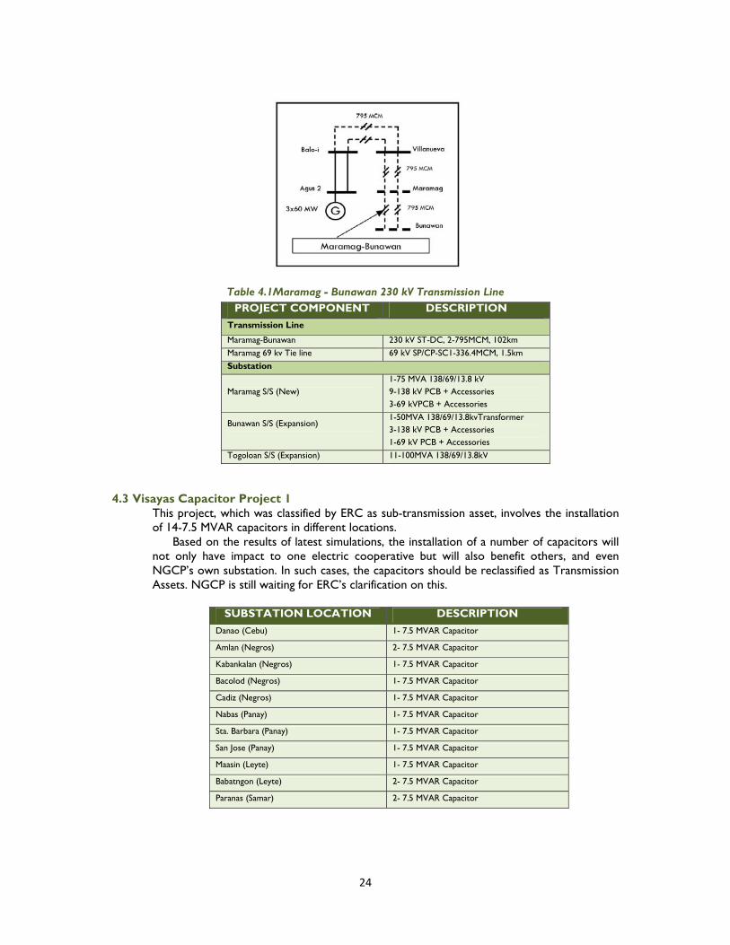
24
Table 4.1Maramag - Bunawan 230 kV Transmission Line PROJECT COMPONENT DESCRIPTION
Transmission Line
Maramag-Bunawan 230 kV ST-DC, 2-795MCM, 102km
Maramag 69 kv Tie line 69 kV SP/CP-SC1-336.4MCM, 1.5km
Substation
Maramag S/S (New) 1-75 MVA 138/69/13.8 kV 9-138 kV PCB + Accessories 3-69 kVPCB + Accessories
Bunawan S/S (Expansion)
1-50MVA 138/69/13.8kvTransformer 3-138 kV PCB + Accessories 1-69 kV PCB + Accessories
Togoloan S/S (Expansion) 11-100MVA 138/69/13.8kV
4.3 Visayas Capacitor Project 1
This project, which was classified by ERC as sub-transmission asset, involves the installation of 14-7.5 MVAR capacitors in different locations.
Based on the results of latest simulations, the installation of a number of capacitors will not only have impact to one electric cooperative but will also benefit others, and even NGCP’s own substation. In such cases, the capacitors should be reclassified as Transmission Assets. NGCP is still waiting for ERC’s clarification on this.
SUBSTATION LOCATION DESCRIPTION
Danao (Cebu) 1- 7.5 MVAR Capacitor
Amlan (Negros) 2- 7.5 MVAR Capacitor
Kabankalan (Negros) 1- 7.5 MVAR Capacitor
Bacolod (Negros) 1- 7.5 MVAR Capacitor
Cadiz (Negros) 1- 7.5 MVAR Capacitor
Nabas (Panay) 1- 7.5 MVAR Capacitor
Sta. Barbara (Panay) 1- 7.5 MVAR Capacitor
San Jose (Panay) 1- 7.5 MVAR Capacitor
Maasin (Leyte) 1- 7.5 MVAR Capacitor
Babatngon (Leyte) 2- 7.5 MVAR Capacitor
Paranas (Samar) 2- 7.5 MVAR Capacitor

25
Chapter 05. Ongoing Projects This chapter discusses in detail the ongoing projects being implemented by NGCP. The projects are classified as Non-network and Network projects. The latter is classified further as follows:
1. Generation-Associated; 2. Load growth-driven; 3. Congestion; and 4. Reliability and Power Quality.
5.1 Non-Network Projects
5.1.1 Hermosa-Quezon 230kV Transmission Line Relocation
The project involves the relocation of a portion of Hermosa-Quezon 230 kV transmission line, with a total length of 14.73 km. The structures, a combination of steel poles and towers, will be relocated along North Luzon Expressway parallel to the viaduct portion from San Simon to Pulilan tollway exits.
This was requested by the Department of Public Works and Highways due to its ongoing road widening activity (from two to six lanes). This road widening is one of the priority projects of the government to decongest traffic at the Manila North Road (formerly McArthur Highway) and provide comfort and alternative route to motorists using the highway. Originally targeted for completion by October 2007, the implementation of the project has to give way to the force majeure projects in southern Luzon as the facilities damaged by the 2006 typhoons have to be prioritized.
Table 5.1.1 Hermosa-Quezon 230 kV T/L Relocation
PROJECT COMPONENT DESCRIPTION
Dismantling/Retiring of Steel poles
Calumpit, Bulacan 2.49 km, 11 steel poles
Apalit, Pampanga 6.73 km, 43 steel poles
Pulilan, Bulacan 5.51 km, 31 steel poles
Relocation (12.5 km)
Viaduct portion 5 km, 18 towers
Remaining portion 7.5 km, 36 steel poles

26
5.2 Generation-Associated Projects
5.2.1 Mariveles Coal Transmission Reinforcement
This project involves the associated grid reinforcements needed to allow the full dispatch of both the proposed Mariveles 600 MW Coal-Fired Power Plant (CFPP) and Limay Combined-Cycle Power Plant (CCPP).
The Mariveles CFPP will be delivering power to the grid through the Limay B-CCPP switchyard, which will be split (isolated) from Limay A-CCPP in order to avoid the need to replace all existing breakers thereat due to increased fault level.
The grid reinforcement involves the reconductoring of the existing Hermosa-Limay B-CCPP 230 kV line (using the existing towers) to maintain the N-1 provision of the line during maximum dispatch of both Mariveles CFPP and Limay B-CCPP units. Additionally, the interrupting capacities of some PCBs at San Jose and Hermosa will also be exceeded and should be replaced. The replacement of these PCBs has been prioritized by NGCP and to date, it is an ongoing project..
The Provisional Authority (PA) to implement the project was secured in March 2008 while the permanent approval for the proposed project was issued by the ERC in August 2008. The project had been delayed thereon due to the non-issuance of Notice to Proceed but will now be implemented because the generation project is already locked-in and committed to be in service on 2012.
Without the project, more than 300 MW generation capacity may be constrained in order to maintain in order to maintain the n-1 provision for Hermosa-Limay B 230 kV Line. Also, the Hermosa and San Jose 230 kV substations will be at risk if the circuit breakers with interrupting capabilities below the expected fault level will not be replaced.
Table 5.2.1 Mariveles Coal Transmission Reinforcement
PROJECT COMPONENT DESCRIPTION Transmission Line
Limay-Limay A-CCPP Tie Line Upgrade 230 kV, SP-DC, 1-410 mm2 TACSR, 0.95 km Hermosa-Limay B-CCPP Line Upgrade Reconductoring with 2-410 mm2 TACSR, 44.6 km
Mariveles-Limay 230 kV, ST-DC, 4-795 MCM, 19 km.
Substation
San Jose 9-230 kV PCB + Accessories (Original components of Luzon PCB Replacement Project)
Hermosa 7-230 kV PCB + Accessories (Original components of Luzon PCB Replacement Project)
Limay B Switchyard 4-230 kV PCB + Accessories

27
5.2.2New Naga Substation
The New Naga Substation is intended to provide a termination point for the Cebu-Negros Uprating. The substation will also establish the asset boundary between NGCP assets and the power plant by separating the control of Salcon Power Complex from NGCP’s substation.
In addition, the substation will serve as the receiving station of the proposed KEPCO 200 MW coal-fired power plant as the old Naga substation is already congested and can hardly accommodate any expansion.
Table 5.2.2 New Naga Substation
PROJECT COMPONENT DESCRIPTION
Transmission Line
Cebu-Quiot-New Naga Cut-in Line 138 kV ST-DC, 1-795 MCM, 0.5 km
Samboan L1 and L2 Extension 138 kV ST-DC, 1-795 MCM, 1.5 km
Toledo and Samboan L3 Extension 138 kV ST-DC1, 1-795 MCM, 1.5 km
Old Naga-New Naga Tie-line (Reconductoring) 138 kV ST-DC, 1-410 mm2 TACSR, 1.0 km
New Naga 69 kV Line Extension (VECO and Sibonga Feeders)
69 kV SP/CP-DC, 1-336.4 MCM, 1.5 km
Substation
New Naga 2-50 MVA 138/69/13.8 kV transformer 16-138 kV PCB + Accessories 4-69 kV PCB + Accessories
Old Naga (Expansion) 2-138 kV PCB + Accessories

28
5.3 Load Growth-Driven Projects
Table 5.3 Load Growth-Driven Projects PROJECT NAME PURPOSE ETC
LUZON
Dasmarinas Substation Expansion To provide N-1 capability to the substation due to load growth 2011
Dasmarinas-Rosario 115 kV Transmission Line
To provide sufficient line capacity and with better line availability
2013
Luzon Substation Expansion 1 To provide additional transformer capacity to meet load growth 2011
VISAYAS
Bohol Backbone Transmission To accommodate load growth, address voltage problems and improve system reliability and flexibility in Bohol
2012
Negros V Transmission Line To provide new transmission corridor to accommodate load growth and attain higher reliability
2013
Negros-Panay Interconnection Uprating (Phase 1)
To improve the voltage profile in Panay and in Negros Occidental, accommodate load growth and improve the system reliability and operational flexibility of the Panay Grid
2011
Northern Panay Backbone To provide 138 kV backbone in Panay to avert overloading of 69 kV lines
2010
Paranas-Carayman Transmission Line To provide new transmission corridor to accommodate load growth and attain higher reliability
2010
Southern Panay Backbone To accommodate load growth and address the low voltage problem in Southern Panay
2012
MINDANAO
Aurora-Polanco 138 kV T/L To accommodate load growth and improve system reliability 2012
Balo-i-Villanueva 230 kV T/L To provide new transmission corridor to Agus Hydro for higher reliability
2011
Mindanao Substation Expansion- 2005 To upgrade existing substations to meet load growth 2011
Sangali-Zamboanga 138 kV T/L To provide new transmission corridor to meet load growth and attain higher reliability
2010
5.3.1 Luzon
5.3.1.1 Dasmariñas Substation Expansion This project is a component of Luzon Transmission Line Upgrading 1 which originally aims to provide N-1 (as the third 300 MVA transformer) at the substation but will now be installed as a replacement to the damaged unit in Dasmariñas.
While the completion of Meralco’s Amadeo 230 kV substation has relieved the loading at Dasmariñas, the installation of a third transformer unit in Dasmariñas is still required to maintain N-1 provision for the transformers as load continues to grow in the coming years.The Dasmarinas EHV Substation Expansion, which is a new project in the Third Regulatory Period, will address this requirement.
Table 5.3.1.1 Dasmariñas Substation Expansion
PROJECT COMPONENT DESCRIPTION Substation
Dasmariñas (Expansion) 1-300 MVA, 230/115 kV 7-230 kV PCB + Accessories 6-115 kV PCB + Accessories

29
5.3.1.2 Dasmariñas-Rosario 115 kV Transmission Line
This project involves the construction of a 16 km, 115 kV transmission line mounted on steel poles and steel towers, including the corresponding expansion of Dasmariñas and Rosario Substations through the installation of additional switching facilities.
The project aims to improve line availability and provide additional capacity to the existing Dasmariñas-Rosario 115 kV wood pole line. The improvement of power supply reliability in the area would further encourage more investors to put up business in Cavite Ecozone.
Table 5.3.1.2 Dasmariñas – Rosario Transmission Line PROJECT COMPONENT DESCRIPTION
Transmission Line
Dasmariñas - New Rosario 115kV , ST/SP-DC, 1-795 MCM, 14.5 km
New Rosario - Old Rosario SP – SC, 2 x 795 MCM, 1.5 km
Substation
Dasmariñas (Expansion) 2-115 kV PCB + Accessories
Old Rosario (replacement of PCB) 1-115 kV PCB + Accessories
5.3.1.3 Luzon Substation Expansion 1 This project involves the installation of additional transformers to accommodate load growth and provide N-1 at various substations. The project components prioritization was based on the latest update on the substation loading forecast. In Mexico, there are five (5) existing 100 MVA transformers and to increase the substation capacity, three (3) of which will be replaced with higher capacity units (2-300 MVA transformers). The replaced unit will then be deployed toother substations needing capacity additions: Bauang, San Rafael and Naga. Cabanatuan and Biñan substations, on the other hand, will have new 200 MVA and 300 MVA transformer units, respectively. To provide N-1, additional 50 MVA capacity will be installed in Bantay while the existing 20 MVA unit in Laoag will be replaced with a new 50 MVA transformer.

30
Table 5.3.1.3 Luzon Substation Expansion 1
SUBSTATION ADDITIONAL
TRANSFORMERS Mexico 2-300 MVA 230/69 kV
Bauang (from Mexico) 1-100 MVA 230/69 kV
San Rafael (from Mexico) 1-100 MVA 230/69 kV
Naga (from Mexico) 1-100 MVA 230/69 kV
Cabanatuan 1-200 MVA 230/69 kV
Laoag 1-50 MVA 115/69 kV
Bantay 1-50 MVA 115/69 kV
Biñan 1-300 MVA 230/115 kV
5.3.2 Visayas
5.3.2.1 Bohol Backbone Transmission
The project involves the installation/construction of a total of 96 kilometers of 138 kV overhead transmission line utilizing steel tower structures and the installation of a 100 MVA power transformer at the new Corella Substation. In addition, the Ubay Substation will be upgraded.
The project is expected to be completed by 2012. The proposed Ubay-Corella 138 kV line is necessary to prevent the overloading of Ubay-Trinidad 69 kV line during outage of Ubay-Alicia 69 kV transmission line, and vice versa, starting 2011. On the other hand, the new substation in Corella will provide a new delivery point in Bohol and prevent the overloading of Ubay Substation starting 2011.
Table 5.3.2.1 Bohol Backbone Transmission
PROJECT COMPONENT DESCRIPTION
Transmission Line
Ubay – Corella 138 kV ST-DC1, 1-795 MCM, 95 km
69 kV Tie-line (Tagbilaran-Catigbian Line) 69 kV SP/CP-DC, 1-336.4 MCM, 0.5 km
Substation
Ubay 2-138 kV PCB + Accessories
Corella 1-100 MVA 138/69/13.8 kV Transformer 1-138 kV PCB + Accessories 3-69 kV PCB + Accessories

31
5.3.2.2 Negros V Transmission Line
This project is intended to accommodate increasing power demand in the northeastern part of Negros island by building a 69 kV transmission loop from Cadiz to Amlan and to ensure the security of power supply to western Negros.
Table 5.3.2.2 Negros V Transmission Line PROJECT COMPONENT DESCRIPTION
Substation
San Carlos-Guihulngan 69 kV ST-SC, 1-336.4 MCM, 52 km
5.3.2.3 Negros-Panay Interconnection Uprating (Phase 1)
Phase 1 of this project or the network upgrading in Panay side is recommended to help improve the voltage profile in Panay and in Negros Occidental. Even with the additional generation in Panay, the high impedance of the single-circuit Dingle-Barotac Viejo 138 kV line will limit the voltage regulation particularly in Negros. It should be noted that Panay and Negros have been prone to voltage variations.
As indicated in the 2009 TDP, Phase I aims to accommodate load growth and address the low voltage problem and improve the system reliability and operational flexibility of the Panay Grid.
The entire Negros-Panay Interconnection Project was approved but optimized down to only 25% by the ERC in the Second Regulatory Period. NGCP has already bid out Phase 1 on 5 April 2010 and subsequently awarded the project to the qualified contractor on 25 May 2010.
Table 5.3.2.3 Negros-Panay Interconnection Uprating (Phase 1) PROJECT COMPONENT DESCRIPTION
Transmission Line
Barotac Viejo CTS-Dingle S/S 138 kV, 1-795 MCM ACSR, ST-DC1, 35 km
Substation
Dingle S/S Expansion 2 x 138 kV PCB + accessories
Barotac Viejo Substation (New) 1 x 50 MVA, 138/69-13.8 kV Transformer 4 x 138 kV PCB + accessories 3 x 69 kV PCB + accessories

32
5.3.2.4 Northern Panay Backbone Transmission
The project involves the installation/construction of a total of 97 kilometers of 138 kV and 69 kV overhead transmission line utilizing steel tower structures and aims to: (1) accommodate load growth and address the low voltage problem; (2) improve the system reliability and operational flexibility; and (3) extend service to un-electrified areas.
Table 5.3.2.4 Northern Panay Backbone Transmission PROJECT COMPONENT DESCRIPTION
Transmission Line
Panitan-Nabas 138 kV ST-DC1, 1-795 MCM, 95 km
Nabas S/S Cut-in to Nabas-Culasi 69 kV T/L 69 kV ST-DC, 1-336.4 MCM, 1.0 km
Nabas S/S Cut-in to Nabas-Caticlan 69 kV T/L 69 kV SP-SC, 1-336.4 MCM, 1.0 km
Substation
Nabas (New) 2-50 MVA 138/69/13.8 kV Transformer 3-138 kV PCB + Accessories 5-69 kV PCB + Accessories
Panitan (Expansion) 1-138 kV PCB + Accessories
5.3.2.5 Paranas-Carayman Transmission Line
To support the long term power requirements of Samar and improve the delivery of quality and reliable power in the island, NGCP is constructing the 138 kV Paranas-

33
Carayman transmission line. The new line will replace the old 69 kV woodpole transmission line and will address the overloading of Paranas Substation.
The absence of reliable transmission infrastructure is probably one of the factors that hamper the economic development of the island. For years, Northern Samar relies on the 69 kV woodpole structures, which are susceptible to tripping that caused power interruptions. Without this project, Carayman will have a load curtailment.
Table 5.3.2.5 Paranas-Carayman 138 kV Transmission Line
PROJECT COMPONENT DESCRIPTION
Transmission Line
Paranas-Carayman 138 kV, ST-DC, 1-795 MCM, 65 km
69 kV tie line 69 kV, SP/CP-DC, 1-336.4 MCM ACSR/AS, 0.2 km
Substation
Paranas S/S 1 x 138 kV PCB + Accessories
Carayman S/S 1 x 50 MVA, 138/69/13.8 kV Transformer 3 x 138 kV PCB + Accessories 3 x 69 kV PCB + Accessories
5.3.2.6 Southern Panay Backbone Transmission
The project is part of the Panay Power Transmission Backbone which involves the installation/construction of a total of 97 kilometers of 138 kV and 69 kV overhead transmission line utilizing steel tower structures. The new transmission backbone will accommodate load growth and address the low voltage problem in southern Panay. In particular, the new facilities will avert the overloading of the Sta. Barbara-Sibalom 69 kV transmission line and the Sta. Barbara Substation.
Table 5.3.2.6 Southern Panay Backbone Transmission
PROJECT COMPONENT DESCRIPTION Transmission Line
Sta. Barbara- San Jose 138 kV ST-DC1, 1-795 MCM, 95 km
San Jose Substation to Cut-in to San Jose -Sibalom 69 kV Line
69 kV ST-DC, 1-336.4 MCM, 2.0 km
Substation
Sibalom Substation (New)
1-50 MVA 138/69/13.8 kV Transformer 2-138 kV PCB + Accessories 3-69 kV PCB + Accessories
Sta. Barbara (Expansion) 2-138 kV PCB + Accessories

34
5.3.3 Mindanao
5.3.3.1 Aurora-Polanco 138 kV Transmission Line
The proposed Aurora-Polanco 138 kV line and the new Polanco Substation are intended to serve the growing power demand of Dipolog City and neighbouring load centers. These new facilities will ensure a continuous and reliable power supply in the area. At present, the City of Dipolog including its neighbouring cities and towns, draw their power requirements from Aurora Substation through a very long 69 kV single circuit woodpole transmission line with a capacity of 47 MW.
Without the proposed facilities, the Aurora-Dipolog 69 kV transmission line and Aurora Substation will be overloaded starting 2011.
Table 5.3.3.1 Aurora-Polanco 138 kV Transmission Line
PROJECT COMPONENT DESCRIPTION
Transmission Line
Aurora-Polanco 138 kV ST-DC, 1-795 MCM, 79 km
Polanco-Polanco (LES) 69 kV SP/CP-DC 1-336.4 MCM, 11 km
Cut-in 69 kV Line 69 kV SC-SP/CP 1-336.4 MCM, 4 km
Substation
Polanco(New) 1-75 MVA 138/69/13.8 kV Transformer 5-138 kV PCB + Accessories 4-69 kV PCB + Accessories
Aurora (Expansion) 3-138 kV PCB + Accessories
Polanco LES 3-69 kV Air Break Switch
5.3.3.2 Balo-i-Villanueva 230 kV Transmission Line

35
The proposed project will provide additional transmission corridor to the 888 MW Agus Hydro Complex (including expected entry of Agus 3 HEP), which accounts for more than40% of Mindanao’s total dependable capacity by year 2013.At present, Agus 2-Kibawe and Balo-i-Tagoloan 138 kV lines serve as Agus Complex’s link to the grid. Over time, the N-1 being provided by these lines to the Agus Complex has been lost due to the increase in demand, i.e., load flow to each of the line. As a result, the bombing of the Agus 2-Kibawe line in the past resulted in huge power swing to the other corridor, the Balo-i-Tagoloan, leading to cascaded tripping of substations and then to system collapse. This project will also serve as an initial step in developing a higher capacity transmission highway from north to south of the grid to meet the increasing demand in Davao area. Due to constraints in acquiring right-of-ways and to serve the long-term requirements of the grid, 230 kV level is deemed necessary for higher transmission capacity. However, this 230 kV-designed transmission line will be energized initially at 138 kV.
Table 5.3.3.2 Balo-i-Villanueva 230 kV Transmission Line PROJECT COMPONENT DESCRIPTION
Transmission Line
Balo-i-Villanueva 230 kV ST-DC, 2-795 MCM, 120 km
Substation
Villanueva(New) 16-138 kV PCB + Accessories
Balo-i 5-138 kV PCB + Accessories
5.3.3.3 Mindanao Substation Expansion-2005 The project involves the installation of additional transformers at the substations identified in Table 5.3.3.3in order to meet load growth. In recent years, load growth in these substations’ coverage areas has significantly increased and expected to continue. The new transformers would also provide N-1 capability to the other substations to mitigate supply interruption during planned and unplanned outages of transformers.
Table 5.3.3.3 Mindanao Substation Expansion- 2005
PROJECT COMPONENT DESCRIPTION
Naga 1-50 MVA 138/69/13.8 kV 1-138 kV PCB + accessories
Butuan 1-100 MVA 138/69/13.8 kV 2-138 kV PCB + accessories 3-69 kV PCB + accessories
5.3.3.4 Sangali-Zamboanga 138 kV Transmission Line

36
This is the remaining component of Zamboanga City 138 kV Transmission Line Project which consists of 33.5-km 138 kV double circuit, steel pole transmission line to be constructed from the existing Sangali substation to new substation in Zamboanga. This augmentation will provide reliable bulk power services to western Mindanao. The project is also intended to remedy operational problem such as line outages, and at the same time meet the projected increase in power demand in the area.
Table 5.3.3.4 Zamboanga City 138 kV Transmission Line
PROJECT COMPONENT
DESCRIPTION
Transmission Line
Sangali-Zamboanga 138 kV SP-DC, 1-795 MCM, 33.5 km
5.4 Congestion
5.4.1 Biñan-Muntinlupa Transmission Line Upgrade
This project involves the construction of the fourth Biñan-Muntinlupa 230 kV transmission line (14 km) circuit (already completed), and the installation of switching facilities at both Biñan and Muntinlupa substations. The project aims to provide provision for N-1 during maximum dispatch of generating plants in south Luzon by increasing the transfer capacity of the Biñan-Muntinlupa transmission corridor. The overloading during N-1 condition is triggered by the tripping of any Biñan-Muntinlupa 230 kV circuits.
Table 5.4.1 Biñan-Muntinlupa Transmission Line Upgrade
PROJECT COMPONENT DESCRIPTION
Transmission Line
Binan – Muntinlupa line 4 230 kV, SP-SC, 2-410 mm2 TACSR, 14 km
Substation
Binan S/S Expansion 1-230 kV PCB + Accessories
Muntinlupa S/S Expansion 1-230 kV PCB + Accessories

37
5.5 Reliability and Power Quality Projects
Table 5 Reliability and Power Quality Projects PROJECT NAME PURPOSE ETC
LUZON
Binga-San Manuel 230 kV T/L (Stage 1) To provide N-1 during maximum dispatch of the generating plants in north Luzon
2012
Binga-San Manuel 230 kV T/L (Stage 2) 2013
Luzon PCB Replacement To replace old PCBs to improve reliability 2012
Luzon Transmission Equipment Upgrade To install the second Labrador-Bolo EHV tie-line and reactors at 500 kV substations in north Luzon
2010
VISAYAS
Visayas PCB Replacement To replace old and antiquated PCBs 2011
MINDANAO
Gen. Santos-Tacurong 138 kV T/L To replace old facilities to meet load growth and attain higher reliability
2011
Mindanao PCB Replacement To replace old and antiquated PCBs 2011
Mindanao Shunt Reactors and Capacitors To correct the overvoltage during off-peak condition 2011
Sultan Kudarat and Nabunturan S/S Expansion (Mindanao Mobile Trasformer Project)
To accommodate load growth and improve system reliability 2012
Villanueva-Maramag 230 kV Transmission Line To complete the transmission corridor from northern to southern Mindanao
2011
5.5.1 Luzon
5.5.1.1 Binga-San Manuel 230 kV Transmission Line
This project involves the construction of a new double circuit Binga-San Manuel 230 kV transmission line (40 km) using new right–of-way, including the installation of switching facilities at Binga Switchyard and San Manuel Substation. Instead of constructing a new Binga Substation, the existing switchyard will be expanded, departing from the original plan of putting up an entirely new substation. The project aims to provide N-1 contingency during maximum dispatch of the generating plants, particularly hydro, in north Luzon. The existing line, as well as the breakers at Binga Substation, which were constructed/installed in 1956 have already surpassed its economic life. Moreover, there are developments in the power plants affecting the power flow at Binga-San Manuel line. These include the repowering of Ambuklao

38
HEP by 2010 to a new capacity of 105 MW (previously at 75 MW capacity) and the completion of Binga HEP expansion by 2014 to an additional capacity of 25 MW. Although approved under the Final Determination of 2nd Regulatory Period, this project was deferred during TransCo time so that its approved disbursement could be allocated to Southern Panay Backbone Project (SPBP).
Table 5.5.1.1 Binga-San Manuel 230 kV Transmission Line PROJECT COMPONENT DESCRIPTION
Transmission Line (Stage 2)
Binga – San Manuel T/L 230 kV, ST-DC, 2-795 MCM, 40 km
Substation (Stage 1)
Binga Substation Expansion 1-75 MVA 230/69-13.8 kV Transformer 10-230 kV PCB + Accessories 2-69 kV PCB + Accessories
San Manuel Substation Expansion 2-230 kV PCB + Accessories
This reallocation would allow the SPBP to be prioritized, as the project was originally proposed to be implemented later than the Binga-San Manuel 230 kV Transmission Line Project.
NGCP, however, will accelerate the implementation of the substation components at Binga which include the installation of a new 75 MVA 230/69 kV transformer and a new control room. The transformer will be serving the Binga-Itogon 69 kV line (a transmission asset) to ensure continuous reliable supply to Baguio PEZA upon disconnection of the said 69 kV line from the 30 MVA 13.2/69 kV transformer inside the Binga HEP switchyard. 5.5.1.2 Luzon Power Circuit Breaker Replacement This project includes 9 x 230 kV and 9 x 115 kV PCBs as replacement for the old units to improve reliability. The 115 kV PCBs included in this package are all classified as transmission assets.
Table 5.5.1.2 Luzon PCB Replacement
SUBSTATION LOCATION DESCRIPTION
San Jose 9-115 kV PCB + Accessories
Labo 3-230 PCB + Accessories
Malaya 4-230 kV PCB + Accessories
Gumaca 2-230 kV PCB + Accessories
5.5.1.3 Luzon Transmission Equipment Upgrade This project involves the following components:
1. Installation of the second Labrador-Kadampat 230 kV tie-line which was already completed in 2008 and was implemented by TEAM Energy, owner of the Sual Coal-Fired Power Plant which is directly affected by the constraints in the said tie-line. It involved the bus-in of BPPC and Bauang 230 kV lines at Kadampat substation with the remaining portion of Labrador-BPPC and Labrador-Bauang (bundled together) serving as the second Labrador-Kadampat tie-line. This project will provide N-1 in this 230 kV segment and would allow the full dispatch of Sual/Masinloc.
2. Installation of 2-90 MVAR shunt reactors at the 500 kV Bolo EHV and San Jose Substations which were energized recently. This will address the overvoltages in the Luzon grid during system off-peak load conditions. Several instrument transformers were already damaged due to the excessive

39
high voltages, prompting the emergency procurement of reactors for Bolo EHV and San Jose substations.
3. Installation of 300 MVA 230/115 kV transformers at Taytay and Doña Imelda substations which werecompleted third quarter of 2010. The transformers were originally included in this project but were deferred as early as the 2006 TDP due to space limitations. These were returned back as components of this project as the replacement of the burnt transformer in Taytay and the critical condition of transformer insulation in Doña Imelda substation. In 2008, TransCo filed an application with the ERC for Provisional Authority (PA) to immediately procure a 300 MVA transformer for Doña Imelda that could make way for the rehabilitation of the transformers one at a time. The additional 300 MVA capacity will eventually become a spare unit.
The components of this project have undergone “reprioritization”, with all project components new, superseding the previously FD-approved components. The ERC, as expressed in their letter to TransCo in 2007, recognizes that circumstances may change within a regulatory period and that the transmission service provider is given flexibility to implement projects which are necessary in performing its mandate.
Table 5.5.1.3 Luzon Transmission Equipment Upgrade
PROJECT COMPONENT DESCRIPTION Transmission Line
Labrador-Kadampat tie line 2 230 kV, ST-DC/SP-SC, 2 x 795 MCM ACSR, 0.319 km and Bauang/BPPC Bus-in at Kadampat 230 kV Substation
Sual-Kadampat Replacement of OHGW with OPGW of existing Sual-Kadampat 230 kV T/L
Substation
Kadampat 6-230 kV PCB + Accessories 2-230 kV PCB + Accessories (Replacement)
Bolo EHV 1 – 90 MVAR, 500 kV Shunt Reactor San Jose 1 – 90 MVAR, 500 kV Shunt Reactor Doña Imelda 1-300 MVA 230/115 kV Transformer
Taytay 1-300 MVA 230/115 kV Transformer
5.5.2 Visayas
5.5.2.1 Visayas Power Circuit Breaker Replacement A Power Circuit Breaker (PCB) is a prime component of power system and is critical for the efficient and sound operation of an electric network. This equipment must be constantly dependable and responsive at any given time. The purpose of this project is to replace old/antiquated PCBs installed in a number of substation facilities including PCBs which will become inadequate in terms of their technical capability (duties, mechanical, etc.)
Under this project, the PCBs in the following substations will be replaced: Amlan, Bacolod, Compostela, Dingle, Mabinay, Panitan and Sta. Barbara.
Table 5.5.2.1 Visayas PCB Replacement
SUBSTATION LOCATION DESCRIPTION
Priority 1
Amlan 5-138 kV PCB + Accessories
Bacolod 2-138 kV PCB + Accessories
Mabinay 3-138 kV PCB + Accessories
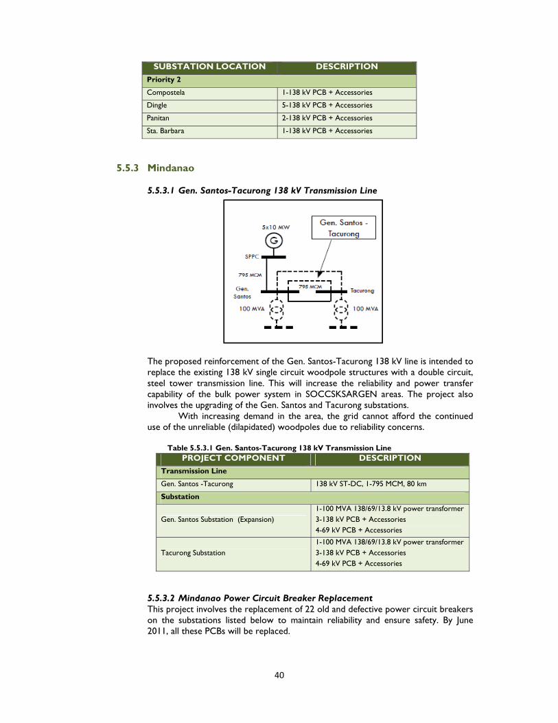
40
SUBSTATION LOCATION DESCRIPTION
Priority 2
Compostela 1-138 kV PCB + Accessories
Dingle 5-138 kV PCB + Accessories
Panitan 2-138 kV PCB + Accessories
Sta. Barbara 1-138 kV PCB + Accessories
5.5.3 Mindanao
5.5.3.1 Gen. Santos-Tacurong 138 kV Transmission Line
The proposed reinforcement of the Gen. Santos-Tacurong 138 kV line is intended to replace the existing 138 kV single circuit woodpole structures with a double circuit, steel tower transmission line. This will increase the reliability and power transfer capability of the bulk power system in SOCCSKSARGEN areas. The project also involves the upgrading of the Gen. Santos and Tacurong substations.
With increasing demand in the area, the grid cannot afford the continued use of the unreliable (dilapidated) woodpoles due to reliability concerns.
Table 5.5.3.1 Gen. Santos-Tacurong 138 kV Transmission Line
PROJECT COMPONENT DESCRIPTION
Transmission Line
Gen. Santos -Tacurong 138 kV ST-DC, 1-795 MCM, 80 km
Substation
Gen. Santos Substation (Expansion) 1-100 MVA 138/69/13.8 kV power transformer 3-138 kV PCB + Accessories 4-69 kV PCB + Accessories
Tacurong Substation 1-100 MVA 138/69/13.8 kV power transformer 3-138 kV PCB + Accessories 4-69 kV PCB + Accessories
5.5.3.2 Mindanao Power Circuit Breaker Replacement This project involves the replacement of 22 old and defective power circuit breakers on the substations listed below to maintain reliability and ensure safety. By June 2011, all these PCBs will be replaced.

41
Table 5.5.3.2 Mindanao PCB Replacement SUBSTATION
LOCATION DESCRIPTION
Priority 1
Bislig 1-138 kV PCB + Accessories
Tacurong 1-138 kV PCB + Accessories
Gen. Santos 1-138 kV PCB + Accessories
Sangali 2-138 kV PCB + Accessories
Sultan Kudarat 1-138 kV PCB + Accessories
Aurora 1-138 kV PCB + Accessories
Davao 2-138 kV PCB + Accessories
Nabunturan 3-138 kV PCB + Accessories
Priority 2
Anislangan 1-138 kV PCB + Accessories
Nabunturan 1-138 kV PCB + Accessories
Davao 1-138 kV PCB + Accessories
Balo-i 2-138 kV PCB + Accessories
Naga 3-138 kV PCB + Accessories
Kibawe 2-138 kV PCB + Accessories
5.5.3.3 Mindanao Shunt Reactors and Capacitors The original components of this project namely: Butuan-San Francisco, San Francisco-Bislig and Bislig-Nabunturan, all of which are 138 kV lines, have been deferred. In lieu of thesecomponents, shunt reactors have been proposed for Bislig and Naga Substations intended to correct the overvoltage during off-peak conditionas well as the undervoltage during peak condition.
Table 5.5.3.3 Mindanao Shunt Reactors and Capacitors
PROJECT COMPONENT DESCRIPTION Substation
Bislig 3-7.5 MVAR 138 kV Shunt Reactors 3-138 kV PCB + Accessories
Naga 2-7.5 MVAR 138 kV Shunt Reactors 2-15 MVAR 138 kV Capacitors 2-138 kV PCB + Accessories
5.5.3.4 Sultan Kudarat and Nabunturan Substation Expansion This project is fully-approved by ERC as Mindanao Mobile Transformer Project but its implementation was deferred in the 2nd Regulatory Period. It was instead replaced with Sultan Kudarat and Nabunturan’s additional transformers which are originallypart of the Mindanao Substation Reliability Project 1.
Table 5.5.3.4 Sultan Kudarat and Nabunturan Substation Expansion
PROJECT COMPONENT DESCRIPTION
Substation
Sultan Kudarat S/S (Expansion) 1-75 MVA 138/69/13.8 kV
Nabunturan S/S (Expansion) 1-100MVA 138/69/13.8kV

42
5.5.3.5 Villanueva-Maramag 230 kV Transmission Line
This approximately 108-kilometer 230 kV, double circuit, steel tower, 2-795 MCM transmission project will complete the Mindanao 230 kV Transmission Backbone linking northern and southern Mindanao.The line will be initially energized at 138 kV.
Table 5.5.3.5 Villanueva-Maramag 230 kV Transmission Line
PROJECT COMPONENT DESCRIPTION
Substation
Villanueva-Maramag 230 kV ST-DC, 2-795 MCM, 108 km

43
Chapter 06.Projects for 2011-2015 This chapter contains the list of projects which NGCP intends to implement and were filed with the ERC in the Third Regulatory Period. It should be noted that to date, ERC has not issued the Final Determination.
Four (4) projects have been approved by the ERC in separate orders. These are Mariveles Coal Transmission Reinforcement and the following 69 kV transmission line projects: Eastern Albay, Sta Rita-Quinapundan and Culasi-Sibalom.
The projects for 2011-2015 are grouped as follows: 1. associated with the expansion or entry of a power plant; 2. network expansion needed to meet load growth; 3. network development needed to resolve congestion; and 4. in compliance with reliability and N-1 requirements of the Grid Code.
Projects intended to meet load growth and reliability requirements get high priority which
became the basis in filing them with ERC. In the case of transformers, those projected to overload are given priority over N-1 (in most cases). In addition, the projected load should be at least 70% on the 10th year after the transformer was installed to ensure optimal utilization of assets.
NGCP’s intention was to come up with a capex level that will result in reasonable transmission rates but would allow it to pursue important network upgrading and expansion. 6.1 Generation-Associated Projects
Table 6.1 Generation-Associated Projects
GENERATION PROJECT REQUIRED GRID
REINFORCEMENT(S) ETC REMARKS
LUZON
Kalayaan III 360 MW
Binan-Muntinlupa Line 4 2010 Completed
Upgrading of Kalayaan-Bay 2012 New Project
San Gabriel Natural Gas 550 MW
Binan-Muntinlupa Line 4 2010
Completed
Upgrading of Kalayaan-Bay Line 2012 New Project
QPPL Coal 500 MW and Pagbilao 375 MW
New 600 MVA 500/230kV transformer at Tayabas (Tayabas S/S Expansion I)
2012 New Project
New line or reconductoring of QPPL-Tayabas Line
Connection asset
Ambuklao Repowering 105 MW / Magat Expansion (180 MW)
Reinforcement of Ambuklao-Binga 2014 Refer to Section
6.3.1
VISAYAS
CEDC Coal 246 MW Reinforcement of Calung-calung-Toledo-New
Naga Line 2013 New Project
6.1.1 Kalayaan-Bay 230 kV Transmission Line Upgrading This project aims to maintain the N-1 provision for the Kalayaan-Bay corridor that could allow all possible generation dispatch scenarios for the associated power plants. There are two proposed generation projects in the area that would further necessitate the upgrading of the Kalayaan-Bay 230 kV transmission line, namely: San Gabriel 550 MW Natural Gas power plant in Batangas and the 360 MW expansion of Kalayaan Pumped Storage Hydroelectric plant in Laguna. The overloading of the Kalayaan-Bay corridor occurs during maximum generation of southern plants (Makban, San Lorenzo, Sta. Rita and Calaca) while Kalayaan is at low dispatch, allowing the output of those plants to flow through the said line.
44
While this may be addressed by limiting the generation of the said plants, this is not a solution being considered as the dispatch schedule is not within NGCP’s control.
Kalayaan-Bay Line is an important corridor in providing operational flexibility particularly during maintenance of the associated transmission lines. It also complements the Biñan-Muntinlupa upgrading project by strengthening this alternate corridor for the generated power from the natural gas plants and the Makban geothermal plant. It helps supply Taytay Substation and also supplies Kalayaan plant during its operation as a pump load.
Even at off-peak hours, overloading also occurs when the natural gas plants (San Lorenzo and Sta. Rita) are still at high output and the Kalayaan units are operating as pumps. The proposed upgrading is a 4-795 MCM ACSR, ST-DC line, with Calauan to be supplied radially from Kalayaan using the existing 1-795 MCM ACSR ST-DC line. The upgrading is also expected to reduce system loss during pumping of Kalayaan units (up to 640 MW load) as the Kalayaan-Bay corridor provides the shortest route from generation sources.
If not implemented, there will be no full flexibility in the dispatch of the power plants (Calaca, Sta. Rita, San Lorenzo, Makban and Kalayaan) in the area. Also, there will be no operational flexibility during transmission line maintenance.
Table 6.1.1 Kalayaan-Bay Transmission Line Upgrading PROJECT COMPONENT DESCRIPTION Transmission Line
Kalayaan-Bay 230 kV, ST-DC 4-795 MCM ACSR, 40 km
Substation
Kalayaan 18-230 kV PCB + Accessories

45
6.1.2 Tayabas Substation Expansion 1
The expansion of Tayabas Substation involves the installation of additional 600 MVA 500/230kV transformer. Upon completion of the project, Tayabas EHV will be at 2,400 MVA total substation capacity. This project is needed to allow all possible generation dispatch scenarios for QPPL and Pagbilao coal plants in Quezon and the power plants in Bicol region to maintain the provision for N-1 at Tayabas EHV Substation.
Table 6.1.2 Tayabas Substation Expansion 1 PROJECT COMPONENT DESCRIPTION
Substation
Tayabas 1-600 MVA 500/230kV
6.1.3 Calung-calung-Toledo-New Naga 138 kV Transmission Line
Upon the completion of CEDC 3x82 MW coal-fired power plant in 2010, Calung-calung-Toledo-New Naga transmission lines need to be reinforced in order to accommodate the said power plant. As of September 2010, two units are in operation already. The project involves the construction of 9.5 kilometers Calung-calung-Toledo and 17.6 kilometers Toledo-New Naga line, with 138 kV steel tower, double circuit overhead transmission line.This project also involves the line extension and termination of VECO’s 138 kV line from CEDC to NGCP’s New Naga Substation.
The reinforcement will cater the estimated 40 MW injected power to the grid by the 100 MW embedded generator connected atToledo Substation. The other 60 MW will be consumed by the embedded loads with modest growth rates. These loads are Carmen Copperand the remaining CEBECO III load.
The project also entails the expansion of Calung-calung, Toledo and New Naga substations.

46
Table 6.1.3 Calung-calung-Toledo-New Naga 138 kV Transmission Line
PROJECT COMPONENT DESCRIPTION Transmission Line
Calung-calung – Toledo 138 kV, ST-DC, 1-795 MCM, 9.5 km
Toledo -New Naga 138 kV, ST-DC, 1-795 MCM, 17.6 km
Colon (VECO) -New Naga S/S 138 kV SP-SC, 2-795 MCM, 0.3 km
Substation
Calung-calung (Expansion) 4-138 kV PCB + Accessories
Toledo (Expansion) 9-138 kV PCB + Accessories
New Naga (Expansion) 2-138 kV PCB + Accessories
6.2 Load Growth-Driven Projects
Table 6.2 Load Growth-Driven Projects PROJECT NAME PURPOSE ETC
LUZON
Luzon Substation Expansion II To provide additional transformer capacity to meet load growth 2015
Luzon Substation Expansion III To provide additional transformer capacity to meet load growth 2013
Luzon Substation Expansion IV To provide additional transformer capacity to meet load growth 2014
New Antipolo 230 kV Substation To serve as a new delivery point in Metro Manila and relieve Taytay Substation
2014
VISAYAS
New Naga-Cebu Transmission Line
To provide additional transformer capacity to meet load growth 2012
Visayas Substation Expansion I To provide additional transformer capacity to meet load growth 2011
MINDANAO
Mindanao Substation Expansion II To provide additional transformer capacity to meet load growth 2014
6.2.1 Luzon
6.2.1.1 Luzon Substation Expansion II This project involves substation capacity expansion to meet load growth of and provide N-1 contingency to various substations in North Luzon. It includes the installation of the third 300 MVA transformer unit for Mexico and additional 100 MVA capacity for the group of steel plant loads, like the Melters Steel Corporation (7.13% growth rate), being served by the substation. The additional capacity will be enough even if the operation of the embedded generators in the area will discontinue. Private distribution utilities connected to Mexico Substation, on the other hand, are anticipated to have significant growth rate for 2010-2015 - Angeles Electric Corporation (6.75%), Pampanga I Electric Cooperative, Inc. (2.95%) Clark Electric Distribution Corporation (2.73%), Pampanga Rural Electric Cooperative (2.02%) and Pampanga III Electric Cooperative, Inc. (1.84%).
The 2-75 MVA transformers at La Trinidad, on the other hand, will be replaced with 2-150 MVA to increase the capacity and provide N-1 contingency for the substation. One of the replaced units will then be installed at Ambuklao to serve the Ambuklao-Beckel 69 kV line (a transmission asset) to further improve the reliability of supply to the customers in the area.
For Concepcion, the additional transformer (the third 100 MVA unit) will be coming from the replaced unit in Mexico Substation. Other customers in the area

47
with projected high growth rate for 2010-2015 are Texas Instrument with 16.84%, Tarlac I Electric Cooperative- 2.83%, Tarlac II Electric Cooperative- 3% and Tarlac Electric Inc.- 2.60%.
Load curtailment will be experienced during transformer outage at the concerned substations. Load curtailment will be higher if some embedded generators cease to operate due to expensive fuel or are under maintenance shutdown.
Table6.2.1.1 Luzon Substation Expansion II
SUBSTATION PROPOSED ADDITIONAL TRANSFORMER
Mexico 1-300 MVA 230/69 kV 1-100 MVA 230/69 kV
Concepcion (from Mexico) 1-100 MVA 230/69 kV
La Trinidad 2-150 MVA 230/69 kV
Ambuklao (from La Trinidad) 1-75 MVA 230/69 kV
Santiago 3-230 kV PCB + Accessories
6.2.1.2 Luzon Substation Expansion III This project involves the installation of a fourth 300 MVA transformer at Las Piñas, one of the major substations serving Metro Manila which requires capacity addition to maintain the provision for N-1 due to high load.
Batangas and Calaca are the other substations that require expansion to meet the load growth. Two units are to be installed (2-300 MVA) in Batangas Substation as replacements for the 2-100 MVA transformers which will at the same time provide N-1 contingency for the substation. One of the replaced units will be installed at Bay Substation for N-1. Majority of the connected customers in Batangas Substation are expected to grow by more than 2% in the next 5 years. The growth rate of the big customers are: Atlantic Gulf & Pacific Company (3.91%), Bobcock-Hitachi (3.09%), San Miguel Foods, Inc. (3.78%), Puyat Steel Corporation (2.33%), Keppel Philippine Shipyard (2.49%), Ibaan Electric & Engineering Corporation (3.53%), BATELEC II (2.61%), Lima Land (3.41%), Philtown (3.51%), Republic Cement (3.26%) and Coco-Chemical Industries (2.48%).
In Calaca, on the other hand, a new 100 MVA transformer (replacing the 50 MVA unit) will be installed in parallel with the existing 100 MVA transformer. Connected loads in the substation have AACGR of more than 2% for the next 5 years: BATELEC I (3.02%) and Steel Corporation of the Philippines (2.73%).
Table 6.2.1.2 Luzon Substation Expansion III
SUBSTATION PROPOSED ADDITIONAL TRANSFORMER
Las Piñas 1-300 MVA 230/115 kV
Batangas 2-300 MVA 230/69 kV
Calaca 1-100 MVA 230/69 kV
Bay (from Batangas) 1-100 MVA 230/69 kV
6.2.1.3 Luzon Substation Expansion IV This project involves the installation of additional transformers at various substations to continuously meet the load growth of the customers being served. The total capacity of the new transformers to be installed under this project is 950 MVA. This includes the installation of the 4th transformer unit for Muntinlupa substation in Metro Manila. For Bayombong and Daraga substations, the units to be installed will be coming from the replaced units in other substations.

48
This package includes one additional transformer in South Luzon at Daraga Substation. The connected loads in this substation are forecasted to increase their demand as the nearby province, Camarines Sur, became the third most visited tourist destination in the country as of the first quarter of 2010 based on the Department of Tourism’s quarterly report. This can be seen from Albay Electric Cooperative’s 4.92%, Sorsogon I Electric Cooperative’s 2.95% and Sorsogon II Electric Cooperative’s 3.59% forecast growth rates for 2010-2015.
The remaining transformers are to be placed in the different substations in North Luzon. In Limay Substation, the connected big loads, Bataan Refining Corporation and Bataan Economic Zone, are expected to grow at an annual average of 3%. In Labrador Substation, on the other hand, the connected cooperatives have relatively higher AACGR: 4.17% for Dagupan Electric Corporation, 3.44% for Pangasinan I Electric Cooperative and 2.29% for Central Pangasinan Electric Cooperative.
In Tuguegarao Substation, one of its connected loads, CAGELCO II, has high forecast with 9.45% AACGR because of the entry of the new airport at Lallo, Cagayan which will complement the Port Irene Seaport, an emerging international transhipment hub and tourism destination in northeastern part of Luzon. Other connected load is CAGELCO I with 3.07% growth rate. Santiago Substation, meanwhile, has a modest 2% growth rate for its loads: Isabela Electric Cooperatives I and II, and Quirino Electric Cooperative. The Nueva Viscaya Electric Cooperative connected in Bayombong substation, on the other hand, has roughly 3% AACGR.
Labrador Substation will be installed with new 100 MVA to cater the load growth of its connected loads: Central Pangasinan Electric Cooperative (2.29%), Pangasinan I Electric Cooperative (3.44%) and Dagupan Electric Corporation (4.17%).
Table 6.2.1.3 Luzon Substation Expansion IV
SUBSTATION PROPOSED ADDITIONAL TRANSFORMER
Muntinlupa 1-300 MVA, 230/115 kV San Manuel 1-200 MVA, 230/69 kV Bayombong (from La Trinidad) 1-75 MVA, 230/69 kV Limay 1-50 MVA, 230/69 kV
Tuguegarao 1-100 MVA, 230/69 kV Santiago 2-100 MVA, 230/69 kV Labrador 1-100 MVA, 230/69 kV Daraga (from Batangas) 1-100 MVA, 230/69 kV
6.2.1.4 New Antipolo 230 kV Substation
This involves the new 230 kV substation that will bus-in along the existing San Jose-Taytay 230 kV line (a 4-795 MCM ST-DC corridor).

49
As load increases in Metro Manila and with the expansion limitation of Doña Imelda and Taytay substations (to serve Meralco’s Sector 2), developing a new 230 kV delivery substation is necessary. By year 2012, Taytay which is at 4-300 MVA capacity will be overloaded already during N-1 condition.
Initially, Antipolo 230 kV substation will be at 2-300 MVA capacity with capacitor banks to be installed for voltage support. To draw supply from Antipolo, MERALCO will have to put up line connections from their existing 115 kV substations near the area such as Masinag, Parang and Marikina.
Outage of one transformer unit in Taytay Substation will necessitate dropping of loads within Metro Manila in order to avoid transformer overloading. Also, voltage problems will be experienced if the 2-100 MVAR capacitors will not be installed.
Table 6.2.1.4 New Antipolo 230 kV Substation
PROJECT COMPONENT DESCRIPTION Transmission Line Extensions from the bus-in point along San Jose- Taytay 230 kV, ST-DC 4-795 MCM ACSR, 8 km
Substation
Antipolo
2-300 MVA 230/115 kV Transformers 12-230 kV PCB + Accessories 6-115 kV PCB + Accessories 2-100 MVAR 230 kV Capacitor
6.2.2 Visayas
6.2.2.1 New Naga-Cebu Transmission Line
The proposed additional circuits are expected to be in place by 2012. The transmission corridor is composed of a double circuit transmission line with 1-795 MCM conductor per circuit, with Quiot Substation cutting in at one circuit. Evidently, a cut-in substation presents an unbalance loading between the two circuits. With two sizable coal plants (3x82 MW CEDC Coal Fired Power Plant and 2x100 MW KEPCO Coal Fired Power Plant) coming-in in Cebu to inject power to the New Naga Substation, and with the expected increase in demand at the Cebu load centers (Cebu, Mandaue and Mactan substations in particular) the New Naga-Cebu transmission corridor will be overloaded. The New Naga-Quiot line will carry the most power.
The project involves the construction of 138 kV double circuit transmission line that utilizes two bundle of 795 MCM conductor per circuit from New Naga directly to Cebu. This new line will only be designed at 138 kV. A 230 kV transmission line from Compostela to New Naga will be proposed to reinforce the future backbone of Cebu.

50
Several electric cooperatives and directly connected industries with a combined load of approximately 400 MW will benefit from the project. Most of them play a crucial role in the economic development of Cebu. The biggest among them are the Visayan Electric Company (305 MW) and Mactan Electric Company (48 MW). The other big customers include Mactan Enerzone Corp. (Aboitiz Land, Inc.) about 22 MW, General Milling Corporation-Cebu (5 MW) and Water Front A/P Hotel and Casino (2 MW).
Table 6.2.2.1 New Naga-Cebu Transmission Line
PROJECT COMPONENT DESCRIPTION
Transmission Line
New Naga-Cebu 138 kV, ST-DC, 2-795 MCM, 25 km
Substation
Cebu Substation 2-138 kV PCB + Accessories
New Naga Substation 5-138 kV PCB + Accessories
6.2.2.2 Visayas Substation Expansion I The demand in the Visayas Grid is expected to grow at an Annual Average Compounded Growth Rate (AACGR) of 4.44% from 2010-2019 based on the NGCP’s latest high demand projection. Three substations were identified to become overloaded under normal condition namely Ormoc (Leyte), Calung-calung (Cebu) and Kabankalan (Negros) substations. The project involves the installation of one (1) unit of 50 MVA transformer for each substation. The Ormoc Substation is serving a combined load of about 21 MW of three electric cooperatives: Biliran, Don Orestes Romualdez and Leyte III, These cooperatives have AACGR for 2010-2015 of 2.76, 3.53 and 11.87%, respectively. The industrial customers connected to Ormoc which will benefit from the expansion include SC Global Coco Products, Specialty Pulp Manufacturing and Visayan Oil Mills. The Calung-calung Substation, on the other hand, serves the power requirements of Balamban Enerzone Corporation (about 19 MW), which is expected to increase the highest by 14.12% up to 2015. In Negros, overloading will be caused by the 2.95% growth rate in Negros Occidental Electric Cooperative which is directly connected to Kabankalan Substation. The additional substation capacities are expected to be in place by 2012 to accommodate the projected load growth.
Table 6.2.2.2 Visayas Substation Expansion 1
SUBSTATION PROPOSED ADDITIONAL TRANSFORMER
Ormoc (Leyte) 1-50 MVA, 138/69kV
Calung-calung (Cebu) 1-50 MVA, 138/69kV
Kabankalan (Negros) 1-50 MVA, 138/69kV
6.2.3 Mindanao
6.2.3.1 Mindanao Substation ExpansionII
This project involves the acquisition of two (2) new transformer units with a total capacity of 200 MVA. The 50 MVA unit at Gen. Santos, which will be replaced by a 100 MVA will be transferred to Sangali.

51
Table 6.2.3.1 Mindanao Substation ExpansionII
SUBSTATION PROPOSED ADDITIONAL TRANSFORMER
Gen. Santos 1-100 MVA, 138/69 kV
Sangali (from Gen. Santos) 1-50 MVA, 138/69 kV
Tagoloan 1-100 MVA, 138/69 kV
6.3 Congestion
Table 6.3 Congestion PROJECT NAME PURPOSE ETC
LUZON
Ambuklao-Binga 230 kV T/L Upgrading
To maintain the provision for N-1 taking into consideration the generation capacity additions from associated Hydroelectric Plants
2016
San Jose-Quezon Line 3 To increase transfer capacity and maintain the N-1 provision 2014
6.3.1 Ambuklao-Binga 230 kV Transmission Line Upgrading
This project aims to upgrade the existing line in order to maintain the provision for N-1 taking into consideration the repowering of Ambuklao plant to a new capacity of 105 MW and the proposed expansion of Magat plant (180 additional capacity). Thus, during maximum generation of both plants, this project will resolve the overloading under N-1 line contingency conditions.
The project involves the construction of a 230 kV 2-410 mm2 TACSR ST-DC transmission line from Ambuklao to Binga Substations that will increase the capacity of the corridor from 2x300 MVA to 2x1100 MVA. This will address the high forecasted growth rate of the customers connected at La Trinidad substation namely: Baguio City Economic Zone,Mountain Province Electric Cooperative,Benguet Electric Cooperative, Inc. and Philex Mining Corporation with growth rates of 4.37, 2.52, 3.49 and 1.14%, respectively. The Line 1 of the existing Ambuklao-Binga 230 kV corridor is more than 50 years old already having been commissioned in 1956. Line 2, on the other hand, was commissioned in 1981.
Table 6.3.1 Ambuklao-Binga 230 kV Transmission Line Upgrading
PROJECT COMPONENT DESCRIPTION Transmission Line
Ambuklao-Binga 230 kV ST-DC 2-410 mm2 TACSR, 11 km
Substation
Ambuklao 6-230 kV PCB + accessories
Binga 5-230 kV PCB + accessories (already included in the Binga-San Manuel 230 kV T/L Project)

52
6.3.2 San Jose-Quezon Line 3 Transmission Line
This project involves the construction of the third circuit for San Jose-Quezon 230 kV transmission corridor. This will increase the transfer capacity of the line to address the overloading problem during tripping of one of the San Jose-Quezon circuits at peak load condition. Without this project, the dispatch of the power plants delivering power to the 500 kV system will have to be limited to maintain the N-1 provision for the line which may also require load dropping within Metro Manila.
The San Jose-Quezon 230 kV lines have a Special Protection System (SPS) that initiates generation shedding and load dropping during outage of both circuits of this corridor. This is to protect the grid from severe disturbances that could lead to a system blackout.
This project shall also complement the capacity addition (from 4-600 MVA to 4-750 MV) at San Jose EHV with the completion of the transformer replacement project thereat, thus improving the overall reliability and security of the grid.
Table 6.3.2 San Jose-Quezon Line 3 Transmission Line
PROJECT COMPONENT DESCRIPTION
Transmission Line
San Jose-Quezon 230 kV, ST-SC 2-610 mm2 TACSR,22 km
Substation
San Jose 2-230 kV PCB + Accessories
Quezon 2-230 kV PCB + Accessories

53
6.4 Reliability and Power Quality Projects
PROJECT NAME PURPOSE ETC
LUZON
Dasmariñas EHV Substation Expansion To maintain the provision for N-1 contingency 2012
Eastern Albay 69 kV Line To maintain the provision for N-1 contingency 2014
Luzon Substation Reliability I To provide N-1 transformers at various substations 2014
Luzon Voltage Improvement I
To maintain the voltage profile at various substaions within the prescribed limits
2013
Luzon Voltage Improvement II
To maintain the voltage profile at various substation within the allowable limits
2014
Magapit Capacitor To improve the voltage profile at Magapit Substation 2012
San Esteban-Laoag 230 kV T/L (Stage 1) To strengthen the existing corridor to provide N-1 and to support the wind farm connections
2013
San Jose-Angat 115 kV Line Upgrading To improve the reliability of the existing corridor. 2014
Santiago-Tuguegarao 230 kV Line 2
To provide N-1 for the existing transmission corridor serving Isabela and Cagayan
2015
VISAYAS
Cebu-Mandaue-Lapu-lapu Transmission Line
To provide N-1 for the existing corridor 2015
Culasi-Sibalom 69 kV Transmission Line To provide N-1 for the existing corridor 2014
Ormoc-Babatngon Transmission Line To provide N-1 for the existing corridor 2014
Ormoc-Maasin Transmission Line To provide N-1 for the existing corridor 2014
Sta. Rita-Quinapundan 69 kV Transmission Line
To provide N-1 for the existing corridor 2014
Visayas Substation Reliability I To provide N-1 transformers at various substations Compostela S/S-
2011 2013
Visayas Substation Reliability II To provide N-1 transformers at various substations 2014
MINDANAO
Agus 6-Aurora 138 kV Transmission Line
To provide security and power quality to North Western Mindanao
2015
Butuan-Placer 138 kV Transmission Project
To provide N-1 capability to the transmission corridor 2013
Maramag-Kibawe 138 kV Transmission Line (Line 3)
To maintain reliability in the southern Mindanao area as additional contingency in case of outage of Agus 2-Kibawe
2014
Matanao-Gen. Santos 138 kV T/L To provide N-1 capability to the transmission corridor 2013
Mindanao Substation Reliability I To provide N-1 transformers at various substations 2014
Tacurong-Sultan Kudarat 138 kV T/L(Sultan Kudarat Capacitor Project)
To provide new transmission corridor from North Cotabato to Maguindanao
2013
6.4.1 Luzon
6.4.1.1 Dasmariñas EHV Substation Expansion This project involves the installation of additional capacity both in the 500 kV and 230 kV substations in Dasmariñas. The 600 MVA capacity expansion at the EHV substation is required in order to maintain the provision for N-1 contingency during maximum dispatch of Ilijan, QPPL and Pagbilao plants (including their generation capacity expansions: 500 MW for QPPL by 2014 and 375 MW for Pagbilao plant by 2017). Similarly, the third 230/115 kV transformer in Dasmariñas will be required in order to maintain the provision for N-1 as the loads, particularly in Metro Manila, being served by the substation continue to grow.

54
This project also involves the replacement of the 230 kV circuit breakers at Dasmariñas as the resulting fault level at the substation will already exceed the interrupting capabilities of the existing breakers.
Table 6.4.1.1 Dasmariñas EHV Substation Expansion PROJECT COMPONENT DESCRIPTION
Substation
Dasmariñas 1-600 MVA 500/230 kV Transformer Bank 2-500 kV PCB + Accessories 14-230 kV PCB + Accessories
1-300 MVA 230/115 kV Transformer 1-230 kV PCB + Accessories 2-115 kV PCB + Accessories
6.4.1.2 Eastern Albay 69 kV Line This is a 69 kV transmission line looping project from Tabaco City to Daraga (via Sto. Domingo) both in the province of Albay. It aims to provide reliable power delivery service to customers located in the three municipalities and two cities in the eastern and southeastern parts of Albay. The project would also provide oppurtunity for direct connection of big industries, e.g., coconut oil mills, cordage manufacturers, etc. including the PEZA-registered Misibis Resort and Spa located in an ecotourism zone at Cagraray Island in Bacacay, Albay. The project may likewise encourage investors to participate in the development of renewable energy sources, such as small hydropower and windpower plants situated in the economically-depressed area with big potential for economic growth.
Table 6.4.1.2 Eastern Albay 69 kV Line
PROJECT COMPONENT DESCRIPTION
(Stage 1) Transmission Line
Tabaco Substation–Sto. Domingo 69 kV, SP/ CP - SC, 1-336.4 MCM, 18 km
Substation
Sto. Domingo (New) 1 x 10 MVA, 69/13.8 kV Power Transformer 2 x 69 kV PCB + Accessories
Tabaco (Expansion) 2 x 69 kV Air Break Switch
(Stage 2) Transmission Line
Daraga Substation–Sto. Domingo 69 kV, ST/ SP - SC, 1-336.4 MCM, 20 km
Substation
Sto. Domingo 1 x 69 kV PCB + Accessories
Daraga 1 x 69 kV PCB + Accessories
6.4.1.3 Luzon Substation Reliability I This project involves the installation of a total of 320 MVA transformer capacity to provide redundancy to various substations with single transformer unit only. The transformers for Labo and San Esteban are new units while the rest will be coming from the replaced transformers in other substations. If not implemented, all of the connected loads in the mentioned substation will have no power supply during transformer failure resulting in unserved energy. In occasions of prolonged transformer outage due to needed repair or rehabilitation, more unserved energy will be incurred.

55
Table 6.4.1.3 Luzon Substation Reliability I
SUBSTATION PROPOSED ADDITIONAL
TRANSFORMER Tayabas (from Biñan) 1-100 MVA, 230/115 kV
Botolan (from Cabanatuan) 1-50 MVA, 230/69 kV
Gumaca (from Calaca) 1-50 MVA, 230/69 kV
Labo 1-50 MVA, 230/69 kV
San Esteban 1-50 MVA, 115/69 kV
Currimao (from Laoag) 1-20 MVA, 115/69 kV
6.4.1.4 Luzon Voltage Improvement I This project has been reclassified as Transmission Asset in the ERC Order Case No. 2005-041RC on July 12, 2010 in response to the Motion for Consideration filed by National Transmission Corporation in 2006. ERC agreed that the installation of the capacitor banks at the high voltage buses of various substations in Luzon to maintain the Grid Code’s prescribed allowable voltage level is to benefit not only the substation supporting the installation but the neighbouring substations as well.
The project involves the installation of shunt reactors in Naga substation and capacitor banks in four (4) substations, namely: Doña Imelda, Cabanatuan, Marilao and Muntinlupa. The shunt reactors in Naga aim to address the overvoltage problem being experienced in the area during off-peak load condition with Tiwi plant at minimum generation. Also, the reactors will address the overvoltage during the switching of the filters in Naga HVDC Station. The capacitor components of this project, on the other hand, will improve the voltage profile during normal conditions and address the potential undervoltages during N-1 contingency conditions. Space availability is a major concern for Doña Imelda and Muntinlupa. In Marilao, a separate adjacent lot will be acquired. NGCP is also considering a bigger lot for the site of a possible 500 kV Marilao drawdown substation. Naga and Cabanatuan have available space to accommodate the installation of the required voltage support equipment.
Though opening of one of the circuits of the Naga-Tayabas 230kV line will mitigate the overvoltages being experienced in Naga Substation during off-peak period, it exposes the transmission line to a vulnerable condition due to reduction in the level of reliability.
Table 6.4.1.4 Luzon Voltage Improvement I
PROJECT COMPONENT DESCRIPTION
Naga 2-25 MVAR 230 kV Reactor
Doña Imelda 1-100 MVAR 230 kV Capacitor
Marilao 3-50 MVAR 230 kV Capacitor
Muntinlupa 2-50 MVAR 115 kV Capacitor
Cabanatuan 1-70 MVAR 230 kV Capacitor
6.4.1.4 Luzon Voltage Improvement II This project involves the installation of a total of 600 MVAR capacitor banks at Biñan, Dasmariñas and Mexico substations in order to improve voltage regulation and keep the voltages in the area within the Grid Code prescribed limits both during normal and N-1 conditions. One of the worst N-1 events for the voltage profile is the outage of Dasmariñas-Ilijan 500 kV line. The increasing load will necessitate the installation of the said capacitor banks by year 2014.

56
Table 6.4.1.4 Luzon Voltage Improvement II PROJECT COMPONENT DESCRIPTION
Dasmariñas 2-100 MVAR, 230 kV Capacitors
Biñan 2-100 MVAR, 230 kV Capacitors
Mexico 2-100 MVAR, 230 kV Capacitors
6.4.1.5 Magapit Capacitor This project is the first stage of the Northeastern Transmission Development. It aims to improve the power quality and reliability of supply particularly in Cagayan which is presently being served by a very long 69 kV line. The project involves the installation of 69 kV capacitors at Magapit as the immediate measure in addressing the voltage problems being experienced in the area. While the proposed extension of the transmission line from Tuguegarao to Magapit will improve the voltage profile in the area, its implementation will take years considering the 78 km long new right-of-way required. There are loads in the area being served by a very long 69 kV line (more than 100 km), thus the need to provide voltage support equipment.
A total of 125 MW proposed capacity addition in Cagayan area has been tapped by NorthWind and First Max Power with their wind farm projects until 2013. Thus if not implemented, the area will not have a strong connection point for the wind farm generation. Also severe voltage problems will be experienced by the loads in the succeeding years.
Table 6.4.1.5 Magapit Capacitor
PROJECT COMPONENT DESCRIPTION
Stage 1: Capacitors
Magapit 3-5 MVAR 69 kV Capacitors 3-69 kV PCB + Accessories
6.4.1.6 San Jose-Angat 115 kV Line Upgrading
This project aims to ensure the reliability of the existing 115 kV transmission lines connecting Angat HEP to the grid. San Jose-Angat Lines 1 and2 were built in 1967 while Line 3 (woodpole) was built in 1960. The proposed project is to construct a new double-circuit line using the existing right-of-way of San Jose-Angat Line 3.
The capacity already anticipates the future retirement of Lines 1 and2 which will be 50 years old already by 2017. Since there are customers connected to the existing lines through tap connection, they will be served by the existing Lines 1 and 2 (radially from San Jose substation) upon completion of the upgrading project. A 115 kV switching station along the upgraded line will be necessary later to provide a connection point for the customers.

57
With this project, the San Jose-Angat 115 kV line will become more reliable corridor. The 300 MVA capacity per circuit of the proposed project would be sufficient to provide N-1 contingency during maximum dispatch of the 246 MW Angat Hydro. If not implemented, constraints will be experienced when Line 3 fails.
Table 6.4.1.6San Jose-Angat 115 kV Line Upgrading
PROJECT COMPONENT DESCRIPTION
Transmission Line
San Jose-Angat 115 kV ST-DC 2-795 MCM, 18 km
Substation
San Jose 2-115 kV PCB + Accessories
6.4.1.7 San Esteban- Laoag 230 kV Transmission Line
The first stage of this two-stage project is being accelerated ahead of the other and is already under construction to date. It involves the construction of 500 meters of 115 kV transmission line and expansion/reconfiguration of the existing Laoag Substation and the installation of control and protection equipment at Laoag, Currimao, Bantay and San Esteban substations. This is intended to accommodate the installation of the connection facility for the two wind power projects: the 86 MW EDC and 80 MW of Northern Luzon UPC Asia Corporation, both of which will connect to Laoag Substation.
The second stage involves the construction of a double-circuit line from San Esteban to Laoag Substation and the construction of new Laoag 230 kV substation. The initial plan was to energize the line at 115 kV but due to increasing wind power capacity that will connect to Laoag Substation and the expansion limitation of San Esteban 115 kV Substation, the line will be energized outright at 230 kV. Currently, there is only one circuit supplying Bantay (from San Esteban), Currimao (from Bantay) and Laoag (from Currimao). Therefore, any outage of line between these stations would result in interruption of power at the receiving stations.
Moreover, this project will strengthen the existing corridor as Ilocos has been identified as one of the areas with high potential for wind power generation. Aside from the existing wind farm (33 MW with additional 8.25 MW capacity) in the area, a total of 513 MW wind generation capacity will be connecting to Laoag within 2010 to 2014.
This project will have a great impact in Ilocos if not implemented. Having only a single 115 kV circuit from San Esteban to Laoag, there will be no N-1

58
reliability for both the load and generation in the northwestern part of the Luzon grid.
Table 6.4.1.7 San Esteban-Laoag 230kV Transmission Line
6.4.1.8 Santiago-Tuguegarao 230 kV Line 2
This project involves the installation of a second circuit from Santiago to Tuguegarao substations bypassing Gamu Substation. This new line will provide reliability as tripping of the existing Santiago-Gamu and Gamu-Tuguegarao 230 kV lines will no longer result in the isolation of the customers at the load end substations in the area.
The project will benefit the northeastern part of the grid by providing reliable power supply. This shall also serve as the first step in strengthening this part of the grid as Cagayan is also among the areas identified to be rich in renewable energy potentials particularly wind.
PROJECT COMPONENT DESCRIPTION
Stage 1: Associated with Wind Farm Projects
Transmission Line
Diversion of Currimao 115 kV Line @ Laoag Substation Expansion Area
SP-SC, 1-795 MCM, 0.50 km
Substation
Laoag S/S Expansion (Reconfigure)
7 – 115 kV PCB + Accessories 1 x 7.5 MVAR, 115 kV Capacitor Bank
Stage 2: 230 kV Transmission System
Transmission Line
San Esteban-Laoag 230 kV, ST-DC, 1-795 MCM, 120 km
Substation
Laoag (New) 6-230 kV PCB + Accessories 2-115 kV PCB + Accessories 2 x 200 MVA, 230/115-13.8 kV Transformer
San Esteban (Expansion) 5 x 230 kV PCB + Accessories

59
Table 6.4.1.8Santiago-Tuguegarao 230 kV Line 2 PROJECT COMPONENT DESCRIPTION
Transmission Line
Santiago-Tuguegarao Line 2 230 kV, ST-SC, 1-795 MCM, 118 km
Substation
Santiago 2-230 kV PCB + Accessories
Tuguegarao 1-230 kV PCB + Accessories
6.4.2 Visayas
6.4.2.1 Cebu-Mandaue-Lapu-Lapu Transmission Line
The existing Cebu-Mandaue-Lapu-lapu transmission line is the transmission corridor carrying the power supply to the two major substations, namely Mandaue and Lapu-lapu, which serve the load center of Metro Cebu. Cebu-Mandaue transmission line is a double circuit line utilizing 3-1400 mm2 XLPE underground cable per circuit. On the other hand, Mandaue-Lapu-lapu is a double circuit utilizing 3-500 mm2 XLPE underground cable per circuit. This transmission corridor is expected to be overloaded by 2011 with the Cebu-Mandaue 138 kV line carrying a heavier power flow compared to the Mandaue-Lapu-lapu 138 kV line.
This project involves the construction of a third circuit utilizing the same conductor as the existing cables to comply with the N-1 provision of the Grid Code. With this project, the reliability of power supply to Mandaue and Lapu-lapu load center substations will be improved.
General Milling Corporation-Cebu, Mactan Enerzone Corporation and Visayan Electric Company are some of the distribution utilities and directly connected customers that will benefit from the project. This improvement will support the economic activities in this area.
Table 6.4.2.1 Cebu-Mandaue-Lapu-lapu Transmission Line
PROJECT COMPONENT DESCRIPTION
Transmission Line
Cebu-Mandaue 138 kV , SC, 3-1400 mm2, 7.2 km
Mandaue-Lapu-lapu 138 kV , SC, 3-500 mm2, 1.5 km
Substation
Mandaue 1-138 kV PCB + Accessories
Lapu-lapu 1-138 kV PCB + Accessories

60
6.4.2.2 Culasi-Sibalom 69 kV Transmission Line
The proposed Culasi-Sibalom T/L was approved by the ERC as transmission asset in its order dated 09 February 2009, ERC Case No. 2007-532MC. Approximately 86 kilometers in length, the transmission line will provide alternate power source to Sibalom Substation, as well as connect North and South Panay on the western side. In the Order, ERC has also decided the reclassification of its connected lines, in the North (Panitan-Nabas Culasi) and South (Sta. Barbara-Sibalom), as transmission assets.
Capiz, Antique and Aklan Electric Cooperatives (CAPELCO, ANTECO and AKELCO) are the distribution utilities connected in north side while Iloilo I and Antique Electric Cooperatives (ILECO I and ANTECO) are connected in the South side. These customers will benefit from this project once the 69 kV loop is completed.
Table 6.4.2.2 Culasi-Sibalom Transmission Line PROJECT COMPONENT DESCRIPTION
Transmission Line
Culasi Load End- Sibalom 69 kV ST-SC, 1-336.4 MCM, 86 km
Substation
Sibalom 2-69 kV PCB + Accessories
Culasi Load End 1-69 kV Air Break Switch
6.4.2.3 Ormoc-Babatngon Transmission Line
Leyte-Samar corridor is composed of Ormoc-Babatngon 138 kV, a single circuit line and Babatngon-Paranas 138 kV, a double circuit line. Since the Ormoc-Babatngon 138 kV is a single circuit line, an outage of this line will result in blackout in Samar. Samar has no internal generation and is dependent from the geothermal generation in Leyte.

61
To prevent this and at the same time comply with N-1 provision of the Grid Code, the Ormoc-Babatngon 138 kV has to be expanded to double circuit line.
This project involves the construction of the 78.54 km of 138 kV steel tower overhead transmission line utilizing 1-795 MCM ACSR conductor as second circuit of the existing Ormoc-Babatngon 138 kV line. This project also involves the expansion of Ormoc and Babatngon substations.
Leyte II Electric Cooperative is one of the customers directly connected to Babatngon Substation that will benefit from the project. This project will support the increase in demand of LEYECO II due to the additional load coming from the connection of Robinson’s Mall.
Table 6.4.2.3 Ormoc-Babatngon Transmission Line
PROJECT COMPONENT DESCRIPTION
Transmission Line
Ormoc-Babatngon 138 kV, ST-DC1, 1-795 MCM, 78.54 km
Substation
Ormoc 1-138 kV PCB + Accessories
Babatngon 1-138 kV PCB + Accessories
6.4.2.4 Ormoc-Maasin Transmission Line
The Leyte-Bohol corridor includes the Ormoc-Maasin 138 kV line, Maasin-Guadalupe CTS 138 kV line, the Guadalupe CTS-C.P. Garcia CTS submarine cable (Leyte-Bohol interconnection) and the C.P. Garcia CTS-Ubay SS 138 kV line. All these lines in the corridor, the Ormoc-Maasin 138 kV in particular, are all single circuit lines. An outage of the Ormoc-Maasin 138 kV line will result to power outage in Bohol as well as Southern Leyte. An initial step to prevent it is the expansion of the Ormoc-Maasin 138 kV to double circuit line. This will also make the line compliant to N-1 provision of the Grid Code.
Leyte IV Electric Cooperative in southern Leyte and the Bohol island will be assured of higher power supply reliability once the project is completed. It will also benefit the eco-tourism activities in Bohol since the island relies heavily on the power supply from Leyte.
Table 6.4.2.4 Ormoc-Maasin Transmission Line
PROJECT COMPONENT DESCRIPTION
Transmission Line
Ormoc-Maasin 138 kV, ST-DC1, 1-795 MCM, 113.97 km
Substation
Ormoc 1-138 kV PCB + Accessories
Maasin 3-138 kV PCB + Accessories

62
6.4.2.5 Sta.Rita-Quinapundan 69 kV Transmission Line
This project was approved by the ERC in its order dated 09 February 2009, ERC Case No. 2007-520MC. The proposed line is intended primarily to make Quinapundan Substation closer to its power source and thus provide power that is more reliable.
At present, the Quinapundan substation gets its power from NGCP's 138 kV Paranas substation via a long stretch of 69 kV wood pole line (Paranas-Taft-Borongan- Quinapundan) that is approximately 191 kilometers long. This corridor is prone to tripping. And because of its distance, low voltage problems and high system loss are also experienced in the area. This project aims to loop the 69 kV line to the existing Sta. Rita substation. Although still a long route, approximately 103 kilometers long, the line shall provide an alternate corridor to the Eastern Samar substations (Paranas, Taft, Borongan and Quinapundan). In case of tripping along Carayman-Taft line, this will also relieve the Paranas substation from overloading.
The delivery substations of Eastern Samar Electric Coopereative, Inc. (ESAMELCO) particularly the Taft, Borongan and Quinapundan Substations will benefit from this project.
Table 6.4.2.5 Sta. Rita-Quinapundan 69 kV Transmission Line PROJECT COMPONENT DESCRIPTION
Transmission Line
Sta. Rita Load End–Quinapundan Load End (initially energized at 69 kV)
138 kV, ST-SC, 1-795 MCM, 103 km
Substation
Sta. Rita Load End (Expansion) 2-69 kV PCB + Accessories
Quinapundan Load End 2-69 kV Air Break Switch
6.4.2.6 Visayas Substation Reliability I This project entails the installation of 650 MVA substation capacity to address overloading of various substations during N-1. These transformers will improve system security and reliability of the grid.
The additional 150 MVA 230/138 kV transformer for Compostela needs to be installed ahead of the others, the reason why NGCP sought Provisional Authority from ERC to proceed with its accelerated implementation. The existing load at Compostela Susbtation has reached a critical level such that if one of the three transformers fails, the two remaining transformers will be overloaded. These are

63
critical transformers as they form part of the Visayas transmission backbone. The bulk power coming from the Leyte geothermal power plants passes through going to the Cebu, Negros and Panay grids.
For the other 7 substations, four have only one transformer, namely: Cadiz, Babatngon, Maasin and Samboan. The loss of a single transformer at any of these substations will interrupt the supply of power to consumers. Therefore, the addition of a second transformer at these substations will establish N-1 capability.
Table 6.4.2.6 Visayas Substation Reliability 1
SUBSTATION PROPOSED ADDITIONAL TRANSFORMER
Compostela (Cebu) 1-150 MVA, 230/138 kV
Ormoc (Leyte) 1-150 MVA, 230/138 kV
Amlan (Negros) 1-50 MVA, 138/69 kV
Bacolod (Negros) 1-100 MVA, 138/69 kV
Cadiz (Negros) 1-50 MVA, 138/69 kV
Babatngon (Samar) 1-50 MVA, 138/69 kV
Maasin (Leyte) 1-50 MVA, 138/69 kV
Samboan (Leyte) 1-50 MVA, 138/69 kV
6.4.2.7 Visayas Substation Reliability Project II This project involves the installation of additional transformers to address overloading of various substations during N-1. For Sta. Barbara, the existing 30 MVA transformer will be replaced with 50 MVA. Among the grids, Visayas has the highest projected growth rate at 4.44% for 2010-2019.
This project is intended to provide capacity additions to various substations to address the overloading during N-1 condition or outage of one transformer. This will ensure the reliability of the substations and comply with the N-1 provision of the Philippine Grid Code.
Table 6.4.2.7 Visayas Substation Reliability II
SUBSTATION PROPOSED ADDITIONAL TRANSFORMER
Mandaue (Cebu) 1-100 MVA, 138/69 kV
Lapu-lapu (Cebu) 1-100 MVA, 138/69 kV
Ormoc (Leyte) 1-50 MVA, 138/69 kV
Sta. Barbara (Panay) 1-50 MVA, 138/69 kV
Sta. Rita (Samar) 1-50 MVA, 138/69 kV

64
6.4.3 Mindanao
6.4.3.1 Agus 6-Aurora 138 kV Transmission Line
This project involves the installation of 1-795 MCM conductor in a double circuit configuration from Agus Complex to Aurora Substation. It will maintain the voltage level at North Western Mindanao during outage of the existing corridor. It will also enhance power security in the area since the existing facility has experienced bombings.
Low voltage being experienced by Lanao del Norte, Misamis Occidental I and II, Zamboanga Norte and Zamboanga Sur electric cooperatives will be avoided once the project is completed.
Table 6.4.3.1 Agus 6-Aurora 138 kV Transmission Line
PROJECT COMPONENT DESCRIPTION
Transmission Line
Agus 6-Aurora 138 kV, ST-DC, 1-795 MCM, 101 km
Substation
Agus 6 (Expansion) 4-138 kV PCB + accessories
Aurora (Expansion) 4-138 kV PCB + accessories
6.4.3.2 Butuan-Placer 138 kV Transmission Project
This project is part of the Reliability Compliance Project I- Mindanao. It involves the installation of the second circuit (approximately 100 kilometers) of the existing Butuan-Placer 138 kV corridor. It will provide N-1 to the existing line and reduce transmission loss and further improve the voltage level in Surigao del Norte. The expected completion of this project is July 2012.

65
Table 6.4.3.2 Butuan Placer 138 kV Transmission Line PROJECT COMPONENT DESCRIPTION
Transmission Line Butuan-Placer 138 kV ST-SC, 1-795MCM, 100km Substation Placer (Expansion) 2-138 kV PCB + Accessories Butuan (Expansion) 2-138 kV PCB + Accessories
6.4.3.3 Maramag-Kibawe 138 kV Transmission Line
The project involves the installation of additional 138 kV single circuit line to strengthen the 138 kV double circuit Maramag-Kibawe transmission line. This is to relieve Maramag-Kibawe 138 kV line from overloading due to the frequent outage of the Agus 2- Kibawe 138 kV line. The project also involves the expansion of Maramag and Kibawe substations.
Table 6.4.3.3 Maramag-Kibawe 138 kV Transmission Line PROJECT COMPONENT DESCRIPTION
Transmission Line
Maramag-Kibawe 138 kV, ST-SC, 1-795 MCM, 21 km
Maramag 1-138 kV PCB + Accessories
Kibawe 3-138 kV PCBs + Accessories
6.4.3.4 Matanao-Gen. Santos 138 kV Transmission Project
This project is part of the Reliability Compliance Project I- Mindanao which involves the provision of N-1 to the existing Matanao- Gen. Santos 138 kV corridor. In case

66
of an outage of the existing Matanao-Gen. Santos line, the Tacurong-Gen. Santos line will not be able to accommodate the load of Gen. Santos Substation starting 2015.
Table 6.4.3.4Matanao-Gen. Santos 138 kV T/L
PROJECT COMPONENT DESCRIPTION
Transmission Line
Matanao-Gen. Santos 138 kV ST- SC, 1-795 MCM, 70 km
Substation
Gen. Santos (Expansion) 2-138 kV PCB + Accessories
Matanao (Expansion) 2-138 kV PCB + Accessories
6.4.3.5 Mindanao Substation Reliability I The project involves the installation of six (6) transformers with a total 325 MVA substation capacity to provide N-1 capability to various substations in Mindanao. The two units of these transformers (for Sultan Kudarat and Nabunturan substations) are proposed as replacements to the Mobile Transformer Project which has been approved by the ERC during the Second Regulatory Period. Other substations that are included in the project are Jasaan, Bunawan, Aurora and Lugait.
Table 6.4.3.5 Mindanao Substation Reliability 1 SUBSTATION
PROPOSED ADDITIONAL TRANSFORMER
Sultan Kudarat 1-75 MVA 138/69-13.8 kV /1 Nabunturan 1-100 MVA 138/69-13.8 kV /1 Jasaan 1-100 MVA 138/69-13.8 kV Bunawan 1-50 MVA 138/69-13.8 kV
Aurora 1-100 MVA 138/69-13.8 kV Lugait 1-75 MVA 138/69-13.8 kV
/1 Replacement for Mindanao Mobile Transformer
6.4.3.6 Tacurong-Sultan Kudarat 138 kV Transmission Line
(Sultan Kudarat Capacitor Project) The proposed 138 kV single circuit steel tower Tacurong-Sultan Kudarat transmission line project is intended to complete the looping within South Western Mindanao Area (SWMA), i.e. General Santos-Tacurong-Sultan Kudarat-Kibawe link, thus providing a strong transmission backbone that will ensure reliable power delivery. However, due to security concerns on the areas traversed by the proposed line, the project could not be implemented.
As a remedial solution to improve the low voltage that will occur in the area during outage of the Kibawe-Sultan Kudarat 138 kV line, 2 x 7.5 MVAR, 69 kV capacitor banks will be installed at the Sultan Kudarat Substation. The implementation of the 138 kV transmission line project as originally proposed, or other option, will be further studied. Maguindanao Electric Cooperative and Cotabato Light and Power Company Inc., with peak demand of about 19 MW and 23 MW, respectively will benefit from this project.

67
CHAPTER 07. PROJECTS BEYOND 2015 (INDICATIVE PROJECTS)
7.1 Generation-Association Projects
PROJECT NAME PURPOSE
Tayabas Substation Expansion II To accommodate the expansion of QPPL and Pagbilao coal plant
Hermosa-Mexico 230 kV Line Upgrading To maintain the N-1 provision for the line during maximum dispatch of Mariveles Coal, Limay and RP Energy Coal plants
RP Energy Coal Plant Associated Project To accommodate the proposed connection of RP Energy Coal plant
Santiago-Bayombong-Ambuklao Line
To allow unconstrained dispatch to the generation capacity expansion of Magat HEP (additional 180 MW) and other incoming plants in the area
Calaca-Dasmariñas Transmission Line
To cater the expansion of Calaca Plant (additional 600 MW) and the entry of Puting Bato Greenfield (135 MW) Coal Plant
Northern Luzon 230 kV Transmission Loop To accommodate the entry of incoming wind farms in Northern Luzon
7.2 Load Growth-Driven Projects
PROJECT NAME PURPOSE
Cut-in to Fort Bonifacio Substation To accommodate the anticipated new delivery point of Meralco inside Fort Bonifacio
Luzon Substation Expansion V To meet the increasing demand at Batangas and Antipolo substations
New Antipolo 500 kV Substation To increase the supply capability of the 500 kV backbone and to improve the reliability of supply to the load center
New Balara 230 kV Substation To provide a new drawdown substation to meet the load growth in Metro Manila and address the overloading of Quezon
New CBP 230 kV Substation and Associated Transmission
To relieve the loading of Las Piñas substation to continuously provide reliable supply to the growing demand of Metro Manila
New Rosario 115kV Substation To serve the growing load of the customers in the area which include the Cavite Ecozone.
Davao-MAA 138 kV Transmission Line To meet the increasing demand at Davao substation

68
7.3 Reliability and Power Quality Projects
PROJECT NAME PURPOSE
LUZON
Luzon Substation Reliability III To maintain the provision for N-1 at various substations
Luzon Voltage Improvement III
To maintain the voltage profile at various substations within the prescribed limits
Luzon Voltage Improvement IV To keep the voltage profile within the prescribed limits both during normal and N-1 conditions
Luzon Voltage Improvement V To keep the voltage profile within the prescribed limits both during normal and N-1 conditions
San Jose 500 kV Reconfiguration To ensure the reliability of the substation and to increase the substation capacity
San Manuel Substation Expansion To provide N-1 and maintain the power quality in the area during contingency
Tuguegarao-Magapit 230 kV Line Extension (Northeastern Transmission Development)
To improve the power quality and reliability of supply to the growing load in the area which include the Cagayan Ecozone
VISAYAS
Amlan-Mabinay Transmission Line To provide N-1 provision to the Negros transmission backbone during low generation at Panay island
Mabinay-Kabankalan-Bacolod Transmission Line To provide N-1 provision to the Negros transmission backbone during low generation at Panay island
Visayas Substation Reliability III To address overloading of various substations during N-1
Visayas Substation Reliability IV To address overloading of various substations during N-1
Visayas Voltage Improvement I To maintain the voltage level at various substations within the Grid Code prescribed limits by installing capacitors
MINDANAO
Mindanao Substation Reliability II To provide N-1 transformers at various substations
Mindanao Substation Reliability III To provide N-1 transformers at various substations
Nasipit Substation Bus-in To improve the power quality and reliability to the growing load in Northeastern Mindanao
Tacurong-Sultan Kudarat 138 kV Line To provide N-1 and maintain power quality in the area of Maguindanao
7.4 Island Interconnection Projects
7.4.1 Visayas In the Visayas, the increase in the demand in each of the island grid must be met, as much as possible, with corresponding additional generation capacity within the island, otherwise the additional or uprating of submarine cable may be considered an option. NGCP is anticipating the uprating of existing Leyte-Bohol and Leyte-Cebu interconnections in the Fourth Regulatory Period (2016-2020). These upratings are necessary to meet load growth and accommodate increased power transfer between the islands.

69
7.4.2 Luzon-Mindoro The proposed Luzon-Mindoro Interconnection Project was approved by the ERC during the Second Regulatory Period. However, the approved capex disbursement for the Second Regulatory Period was about P 2-Million only. Being a “small-capex” project, the said amount was for the pre-construction activities only while the bulk amount for the project will have to be filed for ERC approval for implementation in the Third Regulatory Period.
As a result of NGCP’s project prioritization and to balance capex spending with its impact on transmission tariff, the project was not among the projects filed by NGCP with the ERC for the Third Regulatory Period (2011-2015). Based on the latest estimates, the total project cost of the interconnection is roughly P 5-Billion. In the absence of generation projects in Mindoro and due to the limited demand of the island, the project has been deferred.
The project will connect the Mindoro Island to mainland Luzon through the installation of 25-kilometer submarine cable and 51 kilometers of overhead lines, along with the associated cable terminal stations, voltage conditioning devices and additional switching facilities. The interconnection will give Mindoro Island access to a more stable and reliable source of electricity from the main grid. This, in turn, would result in better economic growth in the island and even make the location of generating plant in the island viable. Due to small demand in Mindoro, the excess generating capacity can be exported to Luzon once the interconnection is in place.
7.4.3 Leyte-Mindanao
The interconnection of Leyte and Mindanao was first conceptualized in the early 1980s through the study conducted by JICA. The government of the Philippines asked the government of Japan to carry out the feasibility study of the Luzon-Leyte Power Transmission Project for the DC transmission line. Between 1984 and 1997, a number of studies were commissioned, from conceptualization to the assessment of technical and economic feasibility of the interconnection. NPC implemented a project in 1997, the Leyte-Mindanao Interconnection Engineering Project, which prepared the plan and the design of the interconnection. Thus, among the studies and relevant activities commissioned with regard to the interconnection, this NPC project financed by the Asian Development Bank (ADB) is the most comprehensive and serious effort to implement the interconnection. Based on this study, the project involves 500 MW submarine cable at ±250 kV

70
HVDC Bipolar configuration, with a total of 544 kilometers transmission line, 23 kilometers of which is for submarine cable.
The economic, financial feasibility and pre-engineering studies for the interconnection will involve substantial budget to complete. No relevant capex was allotted for this project in the Third Regulatory Period but NGCP may initiate regulatory filing. In the conduct of the feasibility study, it has to be established that the interconnection is technically feasible and that its economic and financial benefits are high. The National Government plays a crucial role in the implementation of the interconnection. If the project is feasible, the Government participation is to ensure that its policy and regulations shall allow this economically beneficial capital investment to proceed. Effective regulation will be necessary to ensure that NGCP has financial incentives to proceed with the project.

71
CHAPTER 08. RESIDUAL SUB-TRANSMISSION ASSETS
ERC Resolution No. 18 Series of 2009 provides that residual sub-transmission assets (RSTA) which have not been sold or disposed by 31 December 2010 shall remain as NGCP’s assets. RSTA refers to sub-transmission assets shared by two or more customers. The divestment of connection assets (CA), or those that are used by only one customer, shall continue to be pursued by TRANSCO. Table 8.1 shows the details of these assets.
Table 8.1 Route Length of CA and RSTA
Route Length of
CA1/ in km
Route Length of RSTA2/ in km Total Route
Length in km To be Reverted to the RAB3/
To Remain as RSTA4/
North Luzon 723 665 288 1,677 South Luzon 406 293 149 847
Visayas 894 538 123 1,556 Mindanao 1,290 849 214 2,352
Total 3,314 2,345 773 6,432 Notes: 1/ Sub-Transmission Assets with only one (1) connected customer
2/ Sub-Transmission Assets with two or more connected customers 3/ RSTAs with: (a) two or more connected DISTRIBUTION UTILITIES; and (b) connected generator 4/ RSTAs with: (a) one DU and Directly-connected Customers; (b) Directly-connected customers
It should be noted that in the Second Regulatory Period, the ERC did not expect the financing anymore of sub-transmission projects in 3 to 4 years time. The ERC further opined that the investments needed to maintain, upgrade and expand these sub-transmission assets shall be solely borne by connected customers, who shall eventually acquire the said assets. ERC expected that projects associated with sub-transmission facilities shall already be undertaken by the concerned customers requiring such installations and upgrading.
As a result, without any approved capex allocated for sub-transmission facilities, new investments on rehabilitation and upgrading activities depended on commercial arrangement with the customers.
Across the different grids, there are defective sub-transmission facilities that are undergoing rehabilitation. These are mostly old structures – rotten poles and cross-arms and corroded insulators – that need to be replaced. Low sag must also be corrected through installation of higher poles. Additional expenditures will be lined up by NGCP to ensure the reliable operation of RSTA being maintained by its Operation and Maintenance (O&M) Group. The detailed programs and maintenance activities, which are outlined in TDP Volume II, include the rehabilitation, reinforcement and replacement of sub-transmission line structures and hardware and even the provision of spares for use in case of emergency.
As of 31 October 2010, 3,569.89 ckt-km of RTSA remain with NGCP. This represents about 55% of the total 6,432 ckt-km to be divested. The figures of divested assets for each grid indicated in the following sections refer to sub-transmission lines only and are based on the 31 October 2010 report of TRANSCO.
8.1 Luzon In Luzon, most of the 69 kV sub-transmission lines are radial, i.e., they emanate from 230 kV substations to serve load substations of electric cooperative and direct connect customers without forming any loop. Some of these long 69 kV lines serve remote coastal and isolated mountainous

72
areas, particularly in the eastern side of Luzon. In the northeast, the single circuit feeder originating from the northernmost 230 kV substation (Tuguegarao) extends up to Sta. Ana (122 km) and Abuyong. The coastal town of Ilagan, Isabela is being served by a 73 km line from Santiago Substation. The line serving the Mountain Province is a long 93 km line from the 230 kV La Trinidad Substation to a load-end substation in Bontoc. In the central plain, a 69 kV line from Cabanatuan Substation stretches up 80 km northeast to serve a load-end substation in San Luis, Aurora. For Luzon, a total of 1,055 ckt-km out of 2,524 ckt-km or 42% have been divested. The biggest NGCP customer MERALCO has acquired 140.52 ckt-km of sub-transmission assets. In Central Luzon, a total of 233.38 ckt-km have been acquired already by various distribution utilities and electric cooperatives such as AEC, CELCOR, PENELCO, SFELAPCO, Subic EnerZone, TARELCO II and TEI. Dagupan Electric (DECORP) in Pangasinan has acquired 45.65 ckt-km lines. In northern Luzon, a total of 365.55 ckt-km have been acquired by INEC, LUELCO, LUECO, ABRECO, ISECO and CAGELCO I and II. In south Luzon, about 270 ckt-km have been divested to CASURECO II, MERALCO, Lima Utilities, BATELEC I, BATELEC II, CANORECO and SORECO I.
8.2 Visayas Unlike in Luzon where the 69 kV facilities are generally classified as sub-transmission assets, 69 kV lines in the Visayas remain a significant part of the transmission network. In fact, two (2) 69 kV projects have been approved by ERC during the Second Regulatory Period: the Culasi-Sibalom (Panay) and Sta. Rita-Quinapundan (Leyte) 69 kV line projects. As these projects will loop the existing 69 kV network, the ERC, in approving the said projects, further reclassified to transmission a number of sub-transmission assets affected by the looping. In the Visayas, about 40%, or 615.50 ckt-km out of 1,556 ckt-km of sub-transmission lines have been divested. In Panay, the assets that have been reclassified to transmission are Panitan-Nabas-Culasi and Sta. Barbara-Sibalom corridors. AKELCO and CAPELCO have acquired a total of about 50 ckt-km sub-transmission assets. In October 2009, the ERC through its order under Case No. 2008-088 MC further reclassified the following 69 kV lines in Samar as transmission assets: Paranas (Wright)-SAMELCO II, SAMELCO II-Catbalogan, Catbalogan-Gadgaran, Gadgaran-Palanas Cara, Palanas Cara-Catarman, Catarman-Catubig and Catarman-Allen. In Leyte, the 69 kV network forming a big loop is not operated as such. There are portions that are split by disconnection switches so that the 69 kV lines are radially connected to the 138 kV substations. Due to the resulting configuration with the approval of the Sta. Rita-Quinapundan 69 kV line project, the Paranas-Taft-Borongan-Buenavista loop has been classified as transmission asset. To date, a total of 118.24 ckt-km have been acquired by LEYECO II, LEYECO IV, LEYECO V and DORELCO. In Negros, the eastern side of the grid is being served by 69 kV lines. Once the Negros V Transmission Line Project which will connect San Carlos to Guihulngan is completed, it will form a 69 kV backbone from Cadiz (south) to Amlan (north). About 210 ckt-km of 69 kV lines have been acquired already by NOCECO, CENECO and VRESCO. In Cebu, VECO and MECO sub-transmission facilities serve much of the load located in the business districts of Cebu, Mandaue and Mactan. MECO and VECO have also acquired a number of 69 kV facilities. To date, VECO has acquired 24.56 ckt-km excluding those assets it jointly acquired with

73
CEBECO I. The 69 kV lines that stretch to north (up to Medellin) and south (Alcoy and Dumanjug) serve CEBECO II and CEBECO I, respectively. In Bohol, pending the completion of the Bohol Backbone 138 kV Transmission Backbone, the island relies on 69 kV woodpole backbone. Given the transmission functions of these lines, they are not to be divested. The assets being divested are the 13.8 kV lines, about 16 ckt-km of which have been acquired by BOHECO I, BOHECO II and BLCI.
8.3 Mindanao
Similar to Luzon, the 69 kV lines in Mindanao are radial in nature. Among the long radial lines are the 83 km from Placer 138 kV Substation to Madrid Load-end Substation, Bislig-Cateel-Baganga (86 km), Gen. Santos-Maasim-Kiamba (95 km), Balo-i-Malabang (61 km), Matanao-Malita (70 km) and the 69 kV lines from Naga and Aurora 138 kV substations. A total of about 1,191.4 ckt-km of sub-transmission lines (about 52%) have been divested. Among those that have acquired the assets are SOCOTECO II (215.18 ckt-km), DANECO (193.28 ckt-km), COTELCO (81.44 ckt-km), MORESCO I (62.82 ckt-km) and ANECO (62.62 ckt-km). COTELCO acquired long lines such as Tacurong-Kidapawan 69 kV (43.55 ckt-km) and Kidapawan-Mt Apo (23.69 ckt-km). Other electric cooperatives that have acquired long 69 kV lines are MORELCO II (Nasipit-Gingoog, 41.04 ckt-km) and SOCOTECO I (Tacurong-Koronadal, 28.63 ckt-km).

74

75
Chapter 09. Appendices
Appendix 1.List of Official Site Names of Substations based on the Standard System of Site & Equipment Identification and Labeling(SEIL)- Rev. 1
A1.1 Luzon
NEW NAME OLD NAME
Bay New Makban
Bolo EHV Kadampat EHV
Cawag Hanjin
Dona Imelda Araneta
Florida Blanca Basa
Las Pinas Zapote
Lopez Hondagua
Lumban EHV Kalayaan EHV SS
Malamig Sta. Rosa
Marilao Duhat
Muntinlupa Sucat SS (Old/New)
Naga Converter Station HVDC
Nagsaag EHV San Manuel EHV
Paracale Batobalani
Pilar Putiao
QPPL Quezon
Quezon Balintawak
Rosales Carmen Luzon
Roxas Munoz
San Pascual Gabaldon
San Rafael Cruz Na Daan
Taytay Dolores

76
A1.2 Visayas
NEW NAME OLD NAME
Allen CTS Cabacungan CTS
Barotac Viejo CTS San Juan CTS
Boronggan Cabong
C.P. Garcia CTS Tugas CTS
Calung-calung Talavera Visayas
Carayman Calbayog
Cebu Banilad (VECO)
Daan-Bantayan Talisay Visayas
E.B. Magalona CTS Tomonton CTS/Sarabia CTS
Kananga Tongonan
Lapu-lapu GIS Mactan GIS
Ormoc Converter Station HVDC-OCS
Paranas Wright
Samboan CTS Suba CTS
San Fernando Taiheiyo
Sipalay Maricalum
Sogod LES Lugo LES
Sta. Rita Bagolibas
Tagbilaran Dampas
Toledo Sigpit
A1.3 Mindanao
NEW NAME OLD NAME
Balo-i Abaga
Cagayan de Oro Carmen Mindanao
Gen. Santos Klinan
Iligan Overton
Jasaan Aplaya
Manolofortich Agusan Maramag Pulangi Nabunturan Tindalo
Naga Mindanao Sta. Clara
Oroquieta Villaflor
Ozamis Bañadero
Sultan Kudarat Nuling
Tumaga CBS Lunsuran CBS
Villanueva Kirahon
Zamboanga Pitogo

77
Appendix 2 – Grid Code Performance Standard
Majority of the projects in the TDP are intended to meet load growth and accommodate generation capacity addition. Assumptions are simplified on the type of loads due to uncertainty of the nature of loads that will be connected in the future. For this reason, all performance standard requirements could not all be addressed by the projects in the TDP but are hopefully addressed in the Grid Impact Study (while the customer is applying for a connection), by the System Operator (in real-time), or by the local operation and maintenance personnel. If no project is proposed for the improvement of some of the performance standards, it is not due to oversight, but more on the relevance of a project in the majority of the situations. Table A2 summarizes the Grid Code requirements on power quality and how NGCP intends to satisfy them.
Table A2 Grid Code PQ Standards and the TDP
GRID CODE SECTION
REQUIREMENTS
ADDRESSED BY TDP?
REMARKS
3.2.2 Frequency Variations
Partly
The ability of the TDP to address the constraints provides the adequate corridor for spinning reserves to be made available where it is needed, resulting in the balance of generation and load. This is also addressed in real-time by the System Operator by securing sufficient load following, frequency regulation and spinning reserves.
3.2.3 Voltage Variations Yes Please refer to Section A1.1 Voltage Variation
3.2.4 Harmonics
No
The compensation requirements for loads that generate harmonics are determined in the Grid Impact Study that is conducted during the application of the customer for a connection. The provision for the compensators then becomes a pre-requisite for allowing the connection.
3.2.5 Voltage Unbalance No For planning purposes, all loads and transmission lines are assumed to be balanced. Voltage unbalance will be dealt in real-time.
3.2.6 Voltage Fluctuation and Flicker Severity
No
The compensation requirements for loads that cause voltage fluctuation and flicker are determined in the Grid Impact Study that is conducted during the application of the customer for a connection. The provision for the compensators then becomes a pre-requisite for allowing the connection.
3.2.7 Transient Voltage Variations
No Problems related to transient voltage variations are addressed in the design stage (for expansion projects).
3.3 Reliability Standards
Partly
(projects for N-1 provision)
Reliability Standards, as described in the Grid Code, are based on the total number and duration of sustained power interruption. Improvements in this aspect may be achieved not only through infrastructure projects but by some other means such as proper vegetation management, more systematic and coordinated line restoration and strategic partnership with local citizenry in the maintenance and monitoring of the lines. All of these approaches have been tried to a certain degree on various areas with promising success.
3.4 System Loss Standards Partly This is partly addressed through voltage improvement projects. When economically viable, higher transmission voltage is used to transfer bulk power from generators to loads.
3.5 Safety Standards No
Safety standards requirements are factored-in in the design of the equipment/structure that eventually become part of the specification for the respective projects.
A2.1 Voltage Variation
The Grid Code requires that the long duration voltage variations be greater than 95 percent but
less than 105 percent of the nominal voltage at any connection point during normal conditions (Section 3.2.3.4). The approach used to satisfy this requirement is to improve the voltage at the substations using capacitors and reactors (for inclusion in the TDP) so that it falls within this range,
78
after the transformer taps have been adjusted and reached its limit. Generator terminal voltages are set at 1 per unit (p.u.) and MVAR output is allowed to vary according to the requirements of the Grid Code.
A2.2 System Loss Standard
The system loss of the transmission system is highly dependent on the generation dispatch. If
generating plants output farthest from the load centers are maximized, higher system loss is expected. Without any transmission constraints, the dispatch pattern is not within NGCP’s control but is dictated by the transactions between the generators and the load customers. It follows, therefore, that system loss is not within NGCP’s full control.
The following are the possible solutions to reduce system loss and some issues in implementing
them: • Uprating of the existing transmission line. This can be done through the use of conductors
with larger diameter (and therefore higher capacity) or similar weight conductors but with higher capacity (such as TACSR). Larger but more expensive conductors translate to smaller resistance. Larger diameter conductors, although have larger capacity, would require stronger and hence, more expensive towers. The more expensive Thermal ACSR, on the other hand, are similar in weight but with higher capacity. However, the higher capacity runs the risk of being optimized down in accordance with ERC’s TWRG resulting in under-recovery of investment.
• Use of higher voltages in power transmission. This is an expensive solution, and would take much time to implement. NGCP may implement this strategy whenever the entry of very large generators makes it feasible.
• Improvement of voltage profile. There are projects lined-up to improve the voltages at various substations through installation of capacitor banks. The intention for these projects is not so much to reduce the system loss but to bring the bus voltages to acceptable level. To some extent, this would also result to reduction in system loss.
For benchmarking purposes, system loss cannot be compared to that from other countries
because the dispatch pattern, system configuration, generation and load locations and voltage transmission levels are not the same.
A2.3 Performance Indices
There are currently five (5) performance indices under the Performance Incentive Scheme (PIS),
one of the main features in the Performance-Based Ratemaking (PBR). (a) System Interruption Severity Index (SISI); (b) Frequency Limit Compliance (FLC); (c) Voltage Limit Compliance (VLC); (d) Frequency of Trippings per 100 ckt-km (FOT/100 ckt-km); and (e) System Availability (SA).
Generally, two different approaches are being used for improved performance. The first approach is through infrastructure additions to attain adequacy and ideally, N-1 security. The second approach would be through improved maintenance strategy and quick restoration during failures.
At the transmission level, there are still locations with no provision for N-1 (i.e., there is only a single line supplying the area). There are projects in the TDP which will specifically address this problem.

79
Appendix 3 - Other Projects
The projects listed in Table A3 are requested by some sectors with the hope that they would be classified and approved by the ERC as Transmission Assets. NGCP will seek ERC’s approval of the projects prior to its actual implementation. It should be noted that NGCP will decide on whether to p u r s u e t h e p r o j e c t o r n o t d e p e n d i n g o n r e g u l a t o r y a p p r o v a l .
Table A3 New Projects for ERC Approval
PROJECT NAME PURPOSE
Aglipay-Casiguran 69 kV Line
To provide more reliable power delivery system and meet the projected load growth of Aurora province through NGCP’s Santiago Substation
Tacurong-Kalamansig 69 kV Line
To provide a more reliable power delivery service to the far-flung areas in the province of Sultan Kudarat
A3.1 Aglipay-Casiguran 69 kV Line
In support of the government’s thrust to develop the Aurora Province, NGCP is planning to
implement a sturdier and more reliable power delivery system which will enable Aurora to source its power from NGCP’s Santiago Substation. The existing Santiago– Aglipay 69 kV line needs to be extended by about 115 km up to Casiguran, Aurora. With the recent infrastructure developments in the province of Aurora including the new roads, NGCP is also evaluating other option for the route to be considered for the new transmission line.
Table A3.1 Aglipay-Casiguran 69 kV Line
A3.2 Tacurong-Kalamansig 69 kV Line
The project is envisioned to provide a more reliable power delivery service to the far-
flung areas in the province of Sultan Kudarat. Four municipalities, namely Bagumbayan, Ninoy Aquino, Kalamansig and Lebak will benefit from the project since the power supply to these
PROJECT COMPONENT DESCRIPTION
Transmission Line
Tap Aglipay - Casiguran 69 kV, ST-SC, 1-336.4 MCM ACSR, 115 km
Tap Dinadiawan - Baler 69 kV, ST-SC, 1-336.4 MCM ACSR, 45 km
Substation
Aglipay LE S/S (Expansion) 1-69 kV Air Break Switch
Dinadiawan Tapping Pt. 3-69 kV Air Break Switch
San Luis LE S/S (Expansion)
1-69 kV PCB + Accessories 2-69 kV Air Break Switch 1 X 5 MVAR, 69 kV Capacitor Bank*
Casiguran LE S/S (New)
2-69 kV PCB + Accessories 1 X 10 MVA, 69/13.8 kV Power Transformer 1 X 5 MVAR, 69 kV Capacitor Bank*

80
municipalities are presently being provided by small land based and barge mounted power generating sets of the National Power Corporations’s Small Power Utilities Group (NPC-SPUG). To be considered as part of the grid expansion that intends to increase NGCP’s service area coverage, the project would result to the removal of government subsidy to the present power rate as an off-grid area under NPC-SPUG.
Table A3.2 Tacurong-Kalamansing 69 kV Line
PROJECT COMPONENT DESCRIPTION
Transmission Line
Tacurong–Kalamansig 69 kV, ST-SC, 1-336.4 MCM ACSR, 85 km
Substation
Tacurong S/S (Expansion) 1 x 69 kV PCB + Accessories
Appendix 4 - Existing Island Interconnections
In 2005, two (2) major interconnection projects were completed: the Leyte-Cebu Upgrading (additional 185 MW) and the Cebu-Mactan Interconnection (200 MW). In February 2007, the Cebu-Negros Interconnection Uprating was completed, providing an additional 180 MW capacity between the island.

81
Appendix 5 - Contact Details 1. For all general inquiries regarding the TDP and for making written submissions in respect to network projects described in Chapter 6, you may contact any of the following: Mr. Yuan Mingjun Tel: 63 2 9812555 Head Fax: 63 2 9200025 Transmission Planning Department E-mail: [email protected] Mr. Giovanni R.A. Galang Tel: 63 2 9812514 Deputy Manager Fax: 63 2 9200025 Transmission Planning Department E-mail: [email protected] 2. For inquiries relating to load forecast information, you may contact: Mr. Armando A. Pagayon Tel: 63 2 9812533 Head Fax: 63 2 9200025 Load Forecast and Research E-mail: [email protected] 3. For inquiries relating to ongoing feasibility studies and project approval status: Mr. Vicente N. Loria Tel: 63 2 9812587 Head Fax: 63 2 9213524 Project Planning E-mail: [email protected] 4. For inquiries relating to transmission services: Mr. Philip DV. Dasalla Tel: 63 2 9812595 Head Fax: 63 2 9219584 Marketing E-mail: [email protected]

82