Axles - dezzi.co.za · Axles Type : ZF Model : AP 3085 ... Type : ZF Model : 4WG160
Kentucky Minimum Specifications For School Buses
200910
Kentucky Department of EducationOffice of District Support Services
TABLE OF CONTENTS PAGE
Foreword................................................................................................................................7General Provisions.................................................................................................................8Special Instructions to Suppliers............................................................................................10Acknowledgements................................................................................................................12
SECTION IPART 1
The specifications in this section apply to Type "C" conventional school bus chassis, with a rated pupil capacity of thirty-four (34) through seventy-two (72), and are general specifications for Type "A" sixteen (16) and twenty-two (22) passenger capacity and Type "D" sixty-six (66) through eighty-four (84) passenger school buses.
CHASSIS SPECIFICATION
Air Cleaner.........................................................................................………………………13Axle (front)................................................................................................................………13Axle (rear)..............................................................................................................................14Brakes....................................................................................................................................15Bumper (front).......................................................................................................................18Color......................................................................................................................................19Cooling System......................................................................................................................19Cowl.......................................................................................................................................19Drive Shaft.............................................................................................................................19Electrical System...................................................................................................................20Engine....................................................................................................................................22Exhaust System......................................................................................................................23Fenders (front).......................................................................................................................24Fire Wall................................................................................................................................24Frame.....................................................................................................................................24Frame Lengths.......................................................................................................................25Fuel Tank...............................................................................................................................25Gross Vehicle Weight Rating................................................................................................26Hood.......................................................................................................................................26Horns......................................................................................................................................27Instruments and Instrument Panel..........................................................................................27Lights.....................................................................................................................................28Openings................................................................................................................................28Reflectors...............................................................................................................................28Shock Absorbers....................................................................................................................28Springs (Front-Rear)..............................................................................................................28Steering Column (Wheel)......................................................................................................29Steering Mechanism...............................................................................................................29Tires and Rims.......................................................................................................................29
2009 Kentucky Minimum Standards for School Buses 2
Transmission (Automatic).....................................................................................................30Warranty................................................................................................................................31Wheels....................................................................................................................................31Wheel Alignment...................................................................................................................31
SECTION IPART 2
The specifications in this section apply to Type “C” conventional school bus bodies with a rated pupil capacity of thirty-four (34) through seventy-two (72) and are general specifications for Type “A” sixteen (16) and twenty-two (22) passenger and Type “D” sixty-six (66) through eighty-four (84) passenger school buses.
Accessory Compartment (Driver)..........................................................................................33 Back-Up Alarm......................................................................................................................33Antifreeze...............................................................................................................................33Battery....................................................................................................................................34Body Fluid Clean-Up Kit.......................................................................................................34Bumper (front).......................................................................................................................35Bumper (rear).........................................................................................................................35Ceiling....................................................................................................................................36Color......................................................................................................................................36Construction...........................................................................................................................36Doors – Service Door (Front Entrance Door)........................................................................39Emergency Door (Left Side)..................................................................................................43Emergency Roof Exits/Vents.................................................................................................44Electrical System...................................................................................................................45Engine Housing Cover (Type "D")........................................................................................49Fans (Auxiliary).....................................................................................................................49Fire Extinguisher....................................................................................................................49First Aid Kit...........................................................................................................................49Floor.......................................................................................................................................50Floor Plan...............................................................................................................................52Fuel Fill Cover.......................................................................................................................52Glass.......................................................................................................................................53Heaters...................................................................................................................................53Inside Height..........................................................................................................................55Insulation................................................................................................................................55Interior....................................................................................................................................55Lamps and Signals.................................................................................................................56Lettering.................................................................................................................................62Mirrors...................................................................................................................................63Modifications.........................................................................................................................65Mounting................................................................................................................................65Operating Mechanisms (Identification).................................................................................65Reflective Material.................................................................................................................65Rub Rails................................................................................................................................66Seats (Pupil)...........................................................................................................................67Seats (Driver).........................................................................................................................69Seat Belt (Driver)...................................................................................................................70
2009 Kentucky Minimum Standards for School Buses 3
Sound Pressure Level.............................................................................................................70Steps.......................................................................................................................................70Step Area Grab Handle..........................................................................................................71Stirrup Steps...........................................................................................................................71Storage Compartment............................................................................................................71Strobe Lights..........................................................................................................................71Sunshield................................................................................................................................72Support Equipment................................................................................................................72Undercoating..........................................................................................................................72Ventilation..............................................................................................................................72Warranty................................................................................................................................72Wheelhousings.......................................................................................................................73Wheelhousing Splash Guards................................................................................................73Windows................................................................................................................................73Windshield.............................................................................................................................74Windshield Washers..............................................................................................................75Windshield Wipers.................................................................................................................75
SECTION IIPART 1
The specifications in this section apply to Type "A-2" school bus chassis with a rated pupil capacity of sixteen (16) and twenty-two (22) passenger and sixteen (16) and twenty-two (22) passenger special needs shells.
CHASSIS SPECIFICATIONS
Axle (Front)...........................................................................................................................76Axle (Rear).............................................................................................................................76Axle (Ratio)...........................................................................................................................76Battery....................................................................................................................................76Brakes ...................................................................................................................................77Bumper (Front)......................................................................................................................77Drive Shaft Guards................................................................................................................77Electrical System...................................................................................................................77Engine....................................................................................................................................77Exhaust System......................................................................................................................77Fuel Tank...............................................................................................................................77Fuel Filter...............................................................................................................................78Gross Vehicle Weight Rating................................................................................................78Horns......................................................................................................................................78Power Steering.......................................................................................................................78Shock Absorbers....................................................................................................................78Tires.......................................................................................................................................78Transmission..........................................................................................................................78Wheelbase..............................................................................................................................78Wheels....................................................................................................................................79Windshield.............................................................................................................................79Windshield Washers and Wipers...........................................................................................79
2009 Kentucky Minimum Standards for School Buses 4
SECTION IIPART 2
The specifications in this section apply to Type "A" school bus bodies with a rated pupil capacity of sixteen (16) and twenty-two (22) passenger and sixteen (16) and twenty-two (22) passenger special needs shells.
BODY SPECIFICATIONS
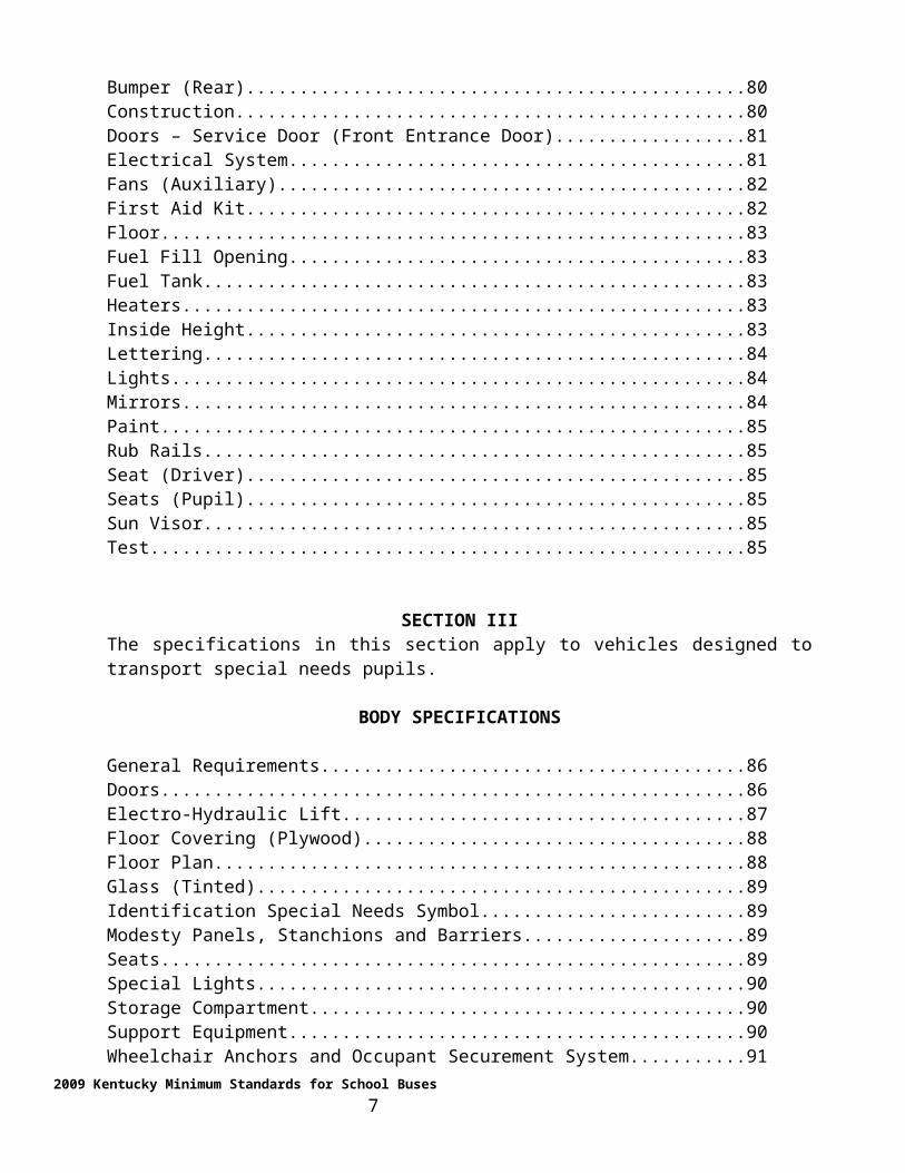
Battery....................................................................................................................................80Bumper (Rear).......................................................................................................................80Construction...........................................................................................................................80Doors – Service Door (Front Entrance Door)........................................................................81Electrical System...................................................................................................................81Fans (Auxiliary).....................................................................................................................82First Aid Kit...........................................................................................................................82Floor.......................................................................................................................................83Fuel Fill Opening...................................................................................................................83Fuel Tank...............................................................................................................................83Heaters...................................................................................................................................83Inside Height..........................................................................................................................83Lettering.................................................................................................................................84Lights.....................................................................................................................................84Mirrors...................................................................................................................................84Paint.......................................................................................................................................85Rub Rails................................................................................................................................85Seat (Driver)...........................................................................................................................85Seats (Pupil)...........................................................................................................................85Sun Visor...............................................................................................................................85Test.........................................................................................................................................85
SECTION IIIThe specifications in this section apply to vehicles designed to transport special needs pupils.
BODY SPECIFICATIONS
General Requirements............................................................................................................86Doors......................................................................................................................................86Electro-Hydraulic Lift............................................................................................................87Floor Covering (Plywood).....................................................................................................88Floor Plan...............................................................................................................................88Glass (Tinted).........................................................................................................................89Identification Special Needs Symbol.....................................................................................89Modesty Panels, Stanchions and Barriers..............................................................................89Seats.......................................................................................................................................89Special Lights.........................................................................................................................90Storage Compartment............................................................................................................90
2009 Kentucky Minimum Standards for School Buses 5
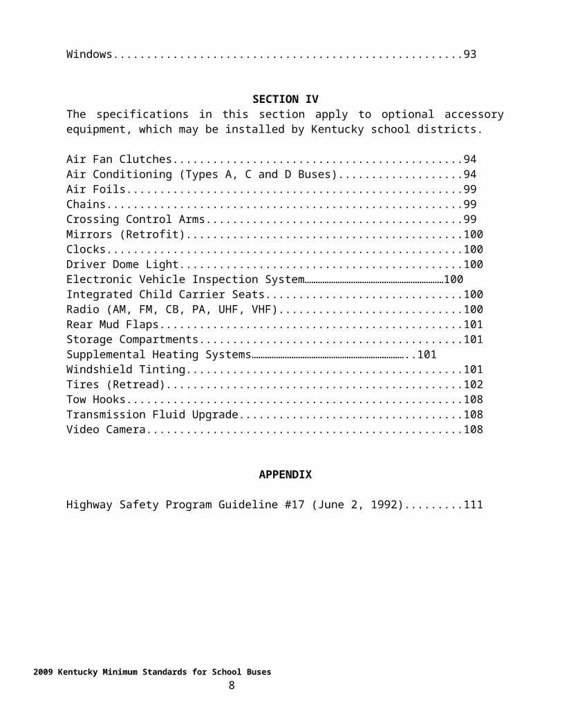
Support Equipment................................................................................................................90Wheelchair Anchors and Occupant Securement System.......................................................91Windows................................................................................................................................93
SECTION IVThe specifications in this section apply to optional accessory equipment, which may be installed by Kentucky school districts.
Air Fan Clutches....................................................................................................................94Air Conditioning (Types A, C and D Buses).........................................................................94Air Foils.................................................................................................................................99Chains....................................................................................................................................99Crossing Control Arms..........................................................................................................99Mirrors (Retrofit)...................................................................................................................100Clocks....................................................................................................................................100Driver Dome Light.................................................................................................................100Electronic Vehicle Inspection System………………………………………………………100Integrated Child Carrier Seats................................................................................................100Radio (AM, FM, CB, PA, UHF, VHF)..................................................................................100Rear Mud Flaps......................................................................................................................101Storage Compartments...........................................................................................................101Supplemental Heating Systems……………………………………………………………..101Windshield Tinting................................................................................................................101Tires (Retread).......................................................................................................................102Tow Hooks.............................................................................................................................108Transmission Fluid Upgrade..................................................................................................108Video Camera........................................................................................................................108
APPENDIX
Highway Safety Program Guideline #17 (June 2, 1992).......................................................111
2009 Kentucky Minimum Standards for School Buses 6
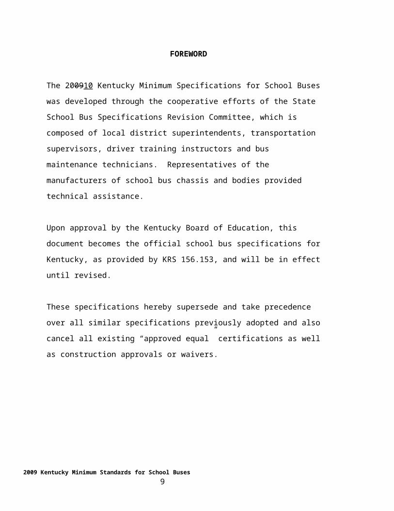
FOREWORD
The 200910 Kentucky Minimum Specifications for School Buses was developed through
the cooperative efforts of the State School Bus Specifications Revision Committee,
which is composed of local district superintendents, transportation supervisors, driver
training instructors and bus maintenance technicians. Representatives of the
manufacturers of school bus chassis and bodies provided technical assistance.
Upon approval by the Kentucky Board of Education, this document becomes the official
school bus specifications for Kentucky, as provided by KRS 156.153, and will be in
effect until revised.
These specifications hereby supersede and take precedence over all similar specifications
previously adopted and also cancel all existing “approved equal” certifications as well as
construction approvals or waivers.
2009 Kentucky Minimum Standards for School Buses 7
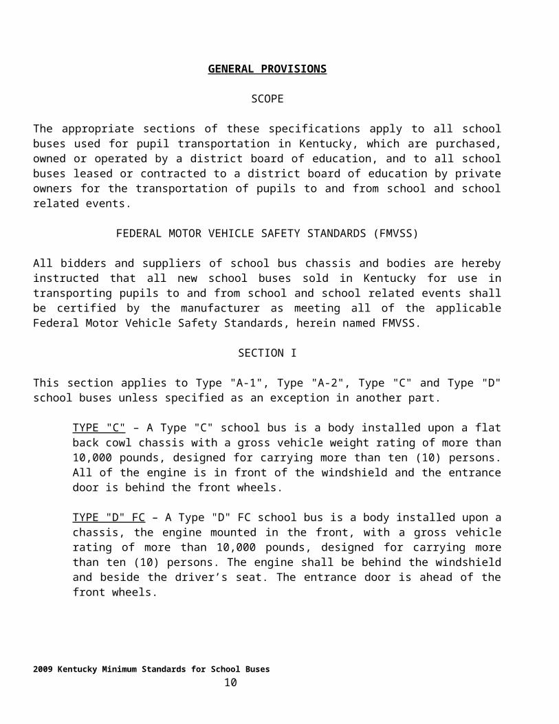
GENERAL PROVISIONS
SCOPE
The appropriate sections of these specifications apply to all school buses used for pupil transportation in Kentucky, which are purchased, owned or operated by a district board of education, and to all school buses leased or contracted to a district board of education by private owners for the transportation of pupils to and from school and school related events.
FEDERAL MOTOR VEHICLE SAFETY STANDARDS (FMVSS)
All bidders and suppliers of school bus chassis and bodies are hereby instructed that all new school buses sold in Kentucky for use in transporting pupils to and from school and school related events shall be certified by the manufacturer as meeting all of the applicable Federal Motor Vehicle Safety Standards, herein named FMVSS.
SECTION I
This section applies to Type "A-1", Type "A-2", Type "C" and Type "D" school buses unless specified as an exception in another part.
TYPE "C" – A Type "C" school bus is a body installed upon a flat back cowl chassis with a gross vehicle weight rating of more than 10,000 pounds, designed for carrying more than ten (10) persons. All of the engine is in front of the windshield and the entrance door is behind the front wheels.
TYPE "D" FC – A Type "D" FC school bus is a body installed upon a chassis, the engine mounted in the front, with a gross vehicle rating of more than 10,000 pounds, designed for carrying more than ten (10) persons. The engine shall be behind the windshield and beside the driver’s seat. The entrance door is ahead of the front wheels.
TYPE "D" RE – A Type "D" RE school bus is a body installed upon a chassis, the engine mounted in the rear, with a gross vehicle weight rating of more than 10,000 pounds, designed for carrying more than ten (10) persons. The engine shall be aft of the rear axle. The entrance door is ahead of the front wheels.
SECTION II
This section applies to Type "A" school buses with a rated pupil capacity of sixteen (16) and twenty-two (22).
TYPE "A" – A Type "A-1" school bus is a conversion or body mounted on a truck chassis cab with a gross vehicle weight rating of 10,000 pounds or less, designed for carrying more than ten (10) persons.
TYPE "A-2" – A Type "A-2" school bus is a conversion or body, constructed upon a van-type compact truck or a front-section vehicle with a gross vehicle weight rating of 10,000 pounds or more, designed for carrying more than ten (10) persons.
2009 Kentucky Minimum Standards for School Buses 8
SECTION III
This section of the specifications applies to those buses designed for the transportation of special needs pupils. The specifications described are minimum specifications for the purpose of transporting special needs students in the Commonwealth of Kentucky. Any special needs requirement needing specification modifications greater than those listed within, or that would fall out of the recognized performance parameter, shall require approval from the Kentucky Department of Education, Division of District Operations, Pupil Transportation Branch.
SECTION IV
The specifications in this section apply to optional accessory equipment that may be installed by Kentucky school districts. Optional equipment installation is not to be considered by manufacturers when preparing bid quotations. Manufacturers may be required to quote on a bid document for the purchase cost of certain optional equipment. Cost of optional equipment in this section shall be borne by the purchasing school district.
MANUFACTURERS’ SERVICE RESPONSIBILITIES
Prior to the award of bid to the successful chassis bidder, the manufacturer of said chassis shall designate an appropriate truck service engineer, based in the zone the of selling dealer, whose purpose shall be to provide service for Kentucky school buses. The designated truck service engineer shall be responsible for Kentucky school buses, regardless of overlapping zone boundaries. The designated truck service engineer shall also be responsible for working with the selling dealer, the Pupil Transportation Branch and the pre-delivery service dealer to ensure purchasers of receiving adequate pre-delivery service and warranty repairs.
Manufacturers of completed Type "D" school buses (chassis and bodies) shall provide for chassis representation in the manner as stated in the preceding paragraph.
PRE-CONTRACT AWARD CONFERENCE
The Pupil Transportation Branch shall request a conference prior to the contract award. The conference, consisting of representatives from the manufacturers, vendors and Pupil Transportation Branch, is for the purpose of determining the ability of the manufacturer and vendor to meet the intent of the 200910 Kentucky Minimum Specifications for School Buses.
CHANGES IN SPECIFICATIONS
Any part of these specifications may be changed at any time by addenda adopted by the Kentucky Board of Education. Changes may be made at any time by the Director of the Pupil Transportation Branch in order to bring the specifications into compliance with the changing FMVSS.
2009 Kentucky Minimum Standards for School Buses 9
VENDOR’S RESPONSIBILITIES
It is the responsibility of all bidders and vendors to avail themselves of any changes in these specifications, made by addenda, and approved by the Kentucky Board of Education after the effective date of these specifications.
CERTIFICATION FOR PURCHASE
Purchasers of Kentucky school buses may receive from the Department of Education, Pupil Transportation Branch, Frankfort, Kentucky, information concerning those manufacturers meeting the requirements as outlined in the 2009 Kentucky Minimum Specifications for School Buses.
Manufacturers shall furnish the Pupil Transportation Branch with necessary information and specifications to determine compliance with the 200910 Kentucky Minimum Specifications for School Buses.
CERTIFICATION OF PRE-DELIVERY SERVICE
All school bus bodies and chassis shall receive pre-delivery service prior to delivery of the completed bus. The chassis and body shall receive the normal manufacturer’s pre-delivery service and complete the requirements of the Pupil Transportation Branch as outlined on the Pre-Delivery Service Form.
SPECIAL INSTRUCTIONS TO SUPPLIERS
PILOT MODEL
Body and/or chassis supplier representatives shall meet with the Pupil Transportation Branch for a pre-pilot conference to clarify and interpret specifications prior to the building of pilot models.
The body and/or chassis supplier shall provide a pilot model that the manufacturer proposes to furnish to meet the 200910 Kentucky Minimum Specifications for School Buses for inspection by representatives of the Department of Education, Pupil Transportation Branch, Frankfort, Kentucky. This is to be done prior to placing the body or chassis into production. All components approved at the time of the pilot model inspection shall be those components installed throughout the completion of the chassis or body build. Subsequent changes, after the pilot model inspection, will require written approval from the Department of Education, Pupil Transportation Branch, and can be made only after a determination of equal has been made.
During construction and/or completion, a representative of the Department of Education, Pupil Transportation Branch, Frankfort, Kentucky, shall have the privilege of inspecting school bus chassis, school bus bodies or any combination thereof. For the purpose of this contract, not more than two (2) pilots and one (1) production visit shall be considered reasonable compliance. Subsequent production/pilot inspections, required at the discretion of the approval agent, shall result in the vendors being charged one thousand dollars ($1,000.00) per additional inspection.
2009 Kentucky Minimum Standards for School Buses 10
SERVICE MANUALS
Body and/or chassis suppliers, including integral suppliers, shall provide each school district purchasing school buses with one complete set of the most current service manuals available, including body, chassis, engine, wiring locator, and body parts manuals at no additional cost. Body and/or chassis suppliers shall also supply one copy of the first level diagnostic software for the engine, brakes and transmission at no additional cost. Providers of integral units shall provide chassis parts manuals in addition to the above at no additional cost. Manuals and software shall be shipped on the basis of one complete set per school district, with the bus invoice, prior to delivery of the completed school bus.
APPROVAL OF DESIGNS, CONSTRUCTION AND EQUIPMENT
In all cases in these specifications, where items are required to be approved as meeting the 2009 Kentucky Minimum Specifications for School Buses and where the specifications state that an "approved equal" will be acceptable, the Department of Education, Pupil Transportation Branch, Frankfort, Kentucky, shall be the approval agency.
In the case of an "approved equal" or an "exception" to the 200910 Kentucky Minimum Specifications for School Buses the school bus chassis manufacturers, the school bus body manufacturers and/or the school bus equipment manufacturers are required to have written approval prior to the installation of an "approved equal" item or an "exception." This information must be presented at the Annual Specifications Revision Meeting with documentation, or must be presented, along with all documentation, to the Pupil Transportation Branch no later than thirty (30) days prior to the bid opening. "Exceptions" or "approved equals" will NOT be accepted for consideration after this date. All approvals accepted shall be warranted for five (5) years.
In order for Kentucky’s school bus purchasers to have the advantage of improved designs, improved type of construction, new and improved equipment and to facilitate the manufacturing and delivery of these buses, said approval agent shall have the discretion to waive minor formalities and variations for these specifications.
In determining the relative merits of certain designs, types of construction and equipment, said approval agent shall have the discretion to authorize the use of certain non-specified designs, types of construction and equipment to be used on an experimental basis, provided that adequate safety measures are maintained.
2009 Kentucky Minimum Standards for School Buses 11
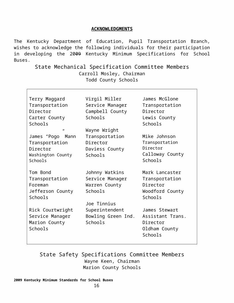
ACKNOWLEDGMENTS
The Kentucky Department of Education, Pupil Transportation Branch, wishes to acknowledge the following individuals for their participation in developing the 2009 Kentucky Minimum Specifications for School Buses.
State Mechanical Specification Committee MembersCarroll Mosley, Chairman
Todd County Schools
Terry MaggardTransportation DirectorCarter County Schools
James “Pogo” MannTransportation DirectorWashington County Schools
Virgil MillerService ManagerCampbell County Schools
Wayne WrightTransportation DirectorDaviess County Schools
James McGloneTransportation DirectorLewis County Schools
Mike JohnsonTransportation DirectorCalloway County Schools
Tom BondTransportation ForemanJefferson County Schools
Rick CourtwrightService ManagerMarion County Schools
Johnny WatkinsService ManagerWarren County Schools
Joe TinniusSuperintendentBowling Green Ind. Schools
Mark LancasterTransportation DirectorWoodford County Schools
James StewartAssistant Trans. DirectorOldham County Schools
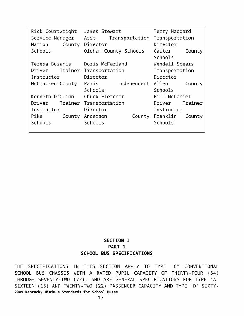
State Safety Specifications Committee MembersWayne Keen, ChairmanMarion County Schools
Rick CourtwrightService ManagerMarion County Schools
James StewartAsst. Transportation DirectorOldham County Schools
Terry MaggardTransportation DirectorCarter County Schools
Teresa BuzanisDriver Trainer InstructorMcCracken County
Doris McFarlandTransportation DirectorParis Independent Schools
Wendell SpearsTransportation DirectorAllen County Schools
Kenneth O’QuinnDriver Trainer InstructorPike County Schools
Chuck FletcherTransportation DirectorAnderson County Schools
Bill McDanielDriver Trainer InstructorFranklin County Schools
2009 Kentucky Minimum Standards for School Buses 12
SECTION IPART 1
SCHOOL BUS SPECIFICATIONS
THE SPECIFICATIONS IN THIS SECTION APPLY TO TYPE "C" CONVENTIONAL SCHOOL BUS CHASSIS WITH A RATED PUPIL CAPACITY OF THIRTY-FOUR (34) THROUGH SEVENTY-TWO (72), AND ARE GENERAL SPECIFICATIONS FOR TYPE "A" SIXTEEN (16) AND TWENTY-TWO (22) PASSENGER CAPACITY AND TYPE "D" SIXTY-SIX (66) THROUGH EIGHTY-FOUR (84) PASSENGER SCHOOL BUSES UNLESS LISTED AS AN EXCEPTION IN SECTION II, PART 1.
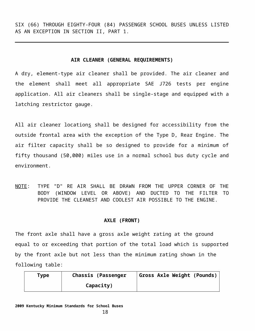
AIR CLEANER (GENERAL REQUIREMENTS)
A dry, element-type air cleaner shall be provided. The air cleaner and the element shall meet all
appropriate SAE J726 tests per engine application. All air cleaners shall be single-stage and equipped with
a latching restrictor gauge.
All air cleaner locations shall be designed for accessibility from the outside frontal area with the exception
of the Type D, Rear Engine. The air filter capacity shall be so designed to provide for a minimum of fifty
thousand (50,000) miles use in a normal school bus duty cycle and environment.
NOTE: TYPE "D" RE AIR SHALL BE DRAWN FROM THE UPPER CORNER OF THE BODY (WINDOW LEVEL OR ABOVE) AND DUCTED TO THE FILTER TO PROVIDE THE CLEANEST AND COOLEST AIR POSSIBLE TO THE ENGINE.
AXLE (FRONT)
2009 Kentucky Minimum Standards for School Buses 13
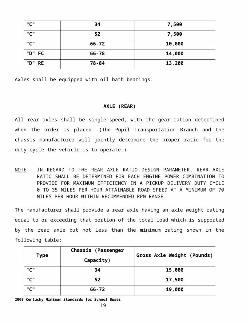
The front axle shall have a gross axle weight rating at the ground equal to or exceeding that portion of the
total load which is supported by the front axle but not less than the minimum rating shown in the
following table:
Type Chassis (Passenger Capacity) Gross Axle Weight (Pounds)
"C" 34 7,500
"C" 52 7,500
"C" 66-72 10,000
"D" FC 66-78 14,000
"D" RE 78-84 13,200
Axles shall be equipped with oil bath bearings.
AXLE (REAR)
All rear axles shall be single-speed, with the gear ration determined when the order is placed. (The Pupil
Transportation Branch and the chassis manufacturer will jointly determine the proper ratio for the duty
cycle the vehicle is to operate.)
NOTE: IN REGARD TO THE REAR AXLE RATIO DESIGN PARAMETER, REAR AXLE RATIO SHALL BE DETERMINED FOR EACH ENGINE POWER COMBINATION TO PROVIDE FOR MAXIMUM EFFICIENCY IN A PICKUP DELIVERY DUTY CYCLE 0 TO 35 MILES PER HOUR ATTAINABLE ROAD SPEED AT A MINIMUM OF 70 MILES PER HOUR WITHIN RECOMMENDED RPM RANGE.
The manufacturer shall provide a rear axle having an axle weight rating equal to or exceeding that portion
of the total load which is supported by the rear axle but not less than the minimum rating shown in the
following table:
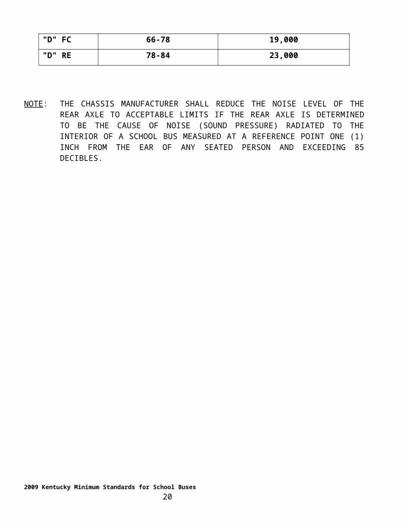
Type Chassis (Passenger Capacity) Gross Axle Weight (Pounds)
"C" 34 15,000
"C" 52 17,500
"C" 66-72 19,000
"D" FC 66-78 19,000
"D" RE 78-84 23,000
2009 Kentucky Minimum Standards for School Buses 14

NOTE: THE CHASSIS MANUFACTURER SHALL REDUCE THE NOISE LEVEL OF THE REAR AXLE TO ACCEPTABLE LIMITS IF THE REAR AXLE IS DETERMINED TO BE THE CAUSE OF NOISE (SOUND PRESSURE) RADIATED TO THE INTERIOR OF A SCHOOL BUS MEASURED AT A REFERENCE POINT ONE (1) INCH FROM THE EAR OF ANY SEATED PERSON AND EXCEEDING 85 DECIBLES.
2009 Kentucky Minimum Standards for School Buses 15
BRAKES
HYDRAULIC BRAKING SYSTEM
All hydraulic brake systems shall utilize the power steering pump as the primary power source, with an
electrical driven power source operating as a secondary system in case of failure of the primary power
source. The hydraulic power brake system shall be Delco-Moraine Hy-Power or prior approved equal. The
brake system shall utilize a power steering pump, or totally separate mounted pump, as the primary power
source.
An electric-driven source to safeguard primary pump failures and electrical protection for the electrical-
driven power source shall be sized to eliminate the interruption of the circuit breaker during service or
continual use.
The failure warning system shall be both visual and audible. The light is to be mounted on the dash. The
audible signal shall be a buzzer-type located in the dash area and shall be loud enough to be easily heard
by the driver. A check of the warning system shall be activated for a system check each time the engine is
turned on.
PARKING BRAKE
The parking brake shall be either the Orscheln lever-type located readily accessible to the driver or the de-
energized spring brake-type located on the rear axle, rear axle driveline or transmission.
Orscheln lever-type parking brakes shall meet the holding requirements as outlined by FMVSS 105, with
no more than seventy (70) pounds applied to the lever arm for engagement or disengagement. Any
Orscheln lever-applied driveline brake shall be of the drum and internal expanding-shoe type. A ratchet-
type, foot-operated parking brake shall be acceptable provided it meets the holding requirements of
FMVSS 105 and is approved by the Pupil Transportation Branch at the pilot inspection.
NOTE: ANY CHASSIS MANUFACTURER USING THE ORSCHELN LEVER-TYPE PARKING BRAKE SHALL EQUIP THE ORSCHELN LEVER SO THAT IT WILL REMAIN AT A FULL REST POSITION, ABSENCE OF SLACK TRAVEL, IN A MANNER THAT WOULD NOT CAUSE MORE THAN SEVENTY (70) POUNDS OF LOAD NEEDED FOR ENGAGEMENT. THE PARKING BRAKE FRICTION MATERIAL SHALL BE ASBESTOS-FREE.
2009 Kentucky Minimum Standards for School Buses 16
GENERAL REQUIREMENTS
All brake lining shall be of asbestos-free material. All hydraulic brake systems 16-22 passenger shall be
equipped with an antilock brake system.
STRAIGHT AIR BRAKES
School bus chassis of thirty-four (34) passenger capacity and larger shall be equipped with "s-cam type"
straight air braking systems. All air brake equipped chassis shall be equipped with Bendix 4-Channel
ABS, Wabco 4-Channel ABS, Wabco 6-Channel or prior approved equal.
The antilock braking system shall be a full vehicle, wheel control, 4-channel system. The antilock system
shall contain an in-dash diagnostic capability. The ABS computer shall be part of the relay valve and
frame rail mounted in a serviceable location or as a separate unit under the dash in a serviceable location.
Manufacturers shall warrant this system for five (5) years.
NOTE: WIRES PASSING THROUGH THE FRAME RAILS SHALL BE GROMMETED TO PREVENT CHAFING.
AIR CHAMBER
Air brakes installed on thirty-four (34) and fifty-two (52) passenger chassis shall be de-rated to provide
balance without aggressive wheel lockup. Type "C" and "D" school bus chassis shall be equipped with the
largest brake chamber compatible with companion axle components. All brake chambers shall be MGM
Long Stroke or approved equal. If the manufacturer anticipates that this requirement will result in any
brake imbalance between axles, it shall be the responsibility of that manufacturer to adjust the chamber
size to produce a balanced brake system.
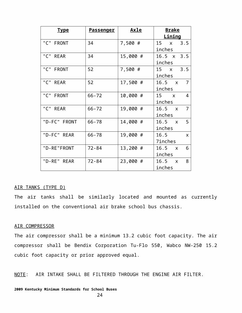
NOTE: ALL LININGS SHALL BE GROUND FOR OPTIMUM DRUM CONTACT. ALL BRAKE
LININGS SHALL EXHIBIT 85% TO 100% LINING TO BRAKE DRUM CONTACT AFTER FMVSS 121 BY DYNAMOMETER TESTING AS REFERENCED FROM THE MID-POINT OF THE SHOE RADIUS. ALL LININGS FOR AIR BRAKE SYSTEMS SHALL BE CONSTRUCTED OF ASBESTOS-FREE MATERIAL AND MEET THE FOLLOWING MINIMUMS:
2009 Kentucky Minimum Standards for School Buses 17
Type Passenger Axle Brake Lining"C" FRONT 34 7,500 # 15 x 3.5 inches"C" REAR 34 15,000 # 16.5 x 3.5 inches"C" FRONT 52 7,500 # 15 x 3.5 inches"C" REAR 52 17,500 # 16.5 x 7 inches"C" FRONT 66-72 10,000 # 15 x 4 inches"C" REAR 66-72 19,000 # 16.5 x 7 inches"D-FC" FRONT 66-78 14,000 # 16.5 x 5 inches"D-FC" REAR 66-78 19,000 # 16.5 x 7inches"D-RE"FRONT 72-84 13,200 # 16.5 x 6 inches"D-RE" REAR 72-84 23,000 # 16.5 x 8 inches
AIR TANKS (TYPE D)
The air tanks shall be similarly located and mounted as currently installed on the conventional air brake
school bus chassis.
AIR COMPRESSOR
The air compressor shall be a minimum 13.2 cubic foot capacity. The air compressor shall be Bendix
Corporation Tu-Flo 550, Wabco NW-250 15.2 cubic foot capacity or prior approved equal.
NOTE: AIR INTAKE SHALL BE FILTERED THROUGH THE ENGINE AIR FILTER.
AIR DRYER
An air dryer shall be installed on all air brake systems. The air dryer shall be Bendix AD-9 or prior
approved equal. Dryers shall be equipped with an internal heater, mounted on the left chassis frame rail or
other approved location, and bracketed for easy serviceability. All of the plumbing from the air
compressor to the input of the air dryer shall be routed for direct entry into the air dryer, utilizing soft flow
bends and eliminating all sumps in air lines. The supply line from the compressor to the air dryer shall be
steel-braided Teflon.
NOTE: INSTALLATION OF THE AIR DRYER AND ROUTING OF THE AIR LINES SHALL REQUIRE PRIOR APPROVAL BY THE PUPIL TRANSPORTATION BRANCH AND THE AIR DRYER MANUFACTURER.
2009 Kentucky Minimum Standards for School Buses 18
NOTE: IF THE STEEL BRAIDED TEFLON SUPPLY LINE IS NOT EXTENDED TO THE AIR DRYER ON TYPE D BUSES, THE BRAIDED PORTION SHALL BE A MINIMUM OF FIVE FEET LONG TO ENSURE THAT ENGINE VIBRATION IS ISOLATED FROM THE AIR DRYER.
GENERAL REQUIREMENTS
A manually operated "pet cock" valve shall be installed on all air tanks indexed for serviceability.
The chassis manufacturer shall provide an accessible accessory outlet for the air-operated stop arm,
subject to the approval of the Pupil Transportation Branch.
The parking brake lever shall be clearly marked and located in convenient reach of the driver in a normal
seated position. The Pupil Transportation Branch shall approve the location of the parking brake valve.
BRAKE ACTUATORS
Brake actuators shall be designed for mounting on the forward side of the rear axle.
SLACK ADJUSTERS (AUTOMATIC)
Automatic slack adjusters shall be installed as original equipment on all air brake systems and have worm
adjustment screws for continuous adjustment with external grease fittings. Automatic slack adjusters shall
be Haldex 400-10-001 or prior approved equal. Grease fitting shall be indexed for serviceability.
ALL AIR BRAKE SYSTEM COMPONENT GROUPS SHALL BE OF THE SAME MANUFACTURER FOR THE TOTAL ORDER. ALL DRUMS SHALL BE EQUIPPED WITH DUST COVERS. THE INSPECTION SIGHT SLOTS SHALL BE INDEXED TO ALLOW EASY VIEWING OF THE FRICTION MATERAL.
Spring brake air chambers shall have a means for manually caging springs.
BUMPER (FRONT – TYPE "C")
The front bumper shall be constructed of steel, a minimum three sixteenths (3/16) inch thick, one piece
construction, a minimum of eight (8) inches in width, ends extending to outer edge of the fender and
closed. The bumper shall be designed and formed to equate in strength in frontal and quarter loading to a
strength that would allow it to support the weight of the vehicle during jacking at selected jacking points.
2009 Kentucky Minimum Standards for School Buses 19
COLOR
All chassis components shall be painted with lead-free paint. The chassis manufacturer shall paint the
Chassis, including the front bumper, black. The front fenders and cowl areas are to be painted "National
School Bus Chrome (Yellow)," in accordance with the colorimetric specification of Federal Standard
595A, Color 13432. (For the color of the hood and grille, refer to "Hood" section.)
NOTE: THE CHASSIS MANUFACTURER SHALL PROVIDE PAINT CHIPS OF THEIR "NATIONAL SCHOOL BUS CHROME (YELLOW)" PAINT BEING PROVIDED ON THE CHASSIS COWL AND HOOD.
COOLING SYSTEM
A coolant recovery system shall be provided. All coolant overflows, if applicable, shall be run outside of
the engine compartment and extend below the frame rail. The coolant system shall be monitored by an
audible and visual signal for over-temperature conditions and shall be located in the driver compartment
(refer to "Engine" section). Coolant shall be extended life coolant TELC ASTM 4985 or fully formulated,
ethylene glycol, long life diesel coolant ASTM D-5345 and ASTM D-6210.
COWL
The dash panel, engine cover, cowl square and position (including the center of the cowl to the chassis
center line) shall be determined at the time the chassis is received by the body company. The chassis
manufacturer shall be responsible to advise and provide documentation to the Department of Education,
Pupil Transportation Branch, and to respective body companies concerning the minimum and maximum
measurements in relation to cowl square and shall provide instructions for chassis receivable personnel
concerning the method of checking.
DRIVE SHAFT (PROPELLER SHAFT)
Either Meritor or Spicer drive shafts are acceptable. The drive shaft and drive shaft components shall be
made and assembled in total by either Meritor or Spicer. All carrier bearings shall have an inner race so
that failure of the bearings shall not damage the drive shaft. Each section of the drive shaft (propeller
shaft) shall be protected by a heavy-duty guard or guards bolted to frame members to prevent it from
whipping through the bus floor or dropping to the ground if broken.
2009 Kentucky Minimum Standards for School Buses 20
NOTE: THE CHASSIS MANUFACTURERS SHALL BE REQUIRED TO DEMONSTRATE THEIR ABILITY TO ENSURE CORRECT DRIVELINE ANGLES, ALIGNMENT AND PHASING PRIOR TO THE BID AWARD.
ELECTRICAL SYSTEM
The electrical system shall be twelve (12) volt.
ALTERNATOR
The electric power source shall be: a heavy-duty, bus-type alternator; a minimum of one hundred
(185)eighty five ampere minimum output at seven thousand five hundred (7,500) RPM rotor speed and a
minimum of seventy four (74) ampere output at normal recommended engine idle speed; driven by a
serpentine belt; designed and sized not to exceed the alternator bearing speed. The rotor shall be of a
diameter that would not be destructive to belts being used. The alternator shall be pad mounted on the top
side of the engine with the regulator indexed for easy service. The regulator shall be preset to fourteen
(14) volts. It shall not have a cold, continuous draw in excess of ten (10) milliamperes and shall be self-
energized with a cut in speed less than low engine idle speed. The alternator shall be Leece-Neville, 4939
PAH or prior approved equal.
VOLTMETER
The chassis shall be equipped with a high-quality voltmeter, energized only when the ignition switch is
on.
BATTERY
All chassis shall require installation of three (3) low maintenance or maintenance-free "Group 31"
batteries. The batteries shall be designed for heavy-duty deep cycling bus operation, constructed of
thermal-rigid hard rubber or heavy plastic case and designed to resist damage from road shock and heat
distortion. The battery shall be a minimum B.C.I group, size 31, twelve (12) volts, one hundred and eighty
(180) ampere-hour capacity, cold-cranking current six hundred and twenty-five (625) amps with top post
terminals.
All batteries mounted by the Type "C" chassis manufacturers shall be temporarily mounted in a manner
readily accessible to the body manufacturers for a skirt sliding tray mounting, without requiring relocation
or length alteration to the battery cables. All battery cables shall be securely routed to the left frame rail
location without crossing over the top of any frame member. Routing and clamping of conductors shall be
2009 Kentucky Minimum Standards for School Buses 21
pre-engineered to the point of termination outside the left frame rail. Both battery cables shall attach to the
battery posts, or battery terminals, with a bolted connector. Type "D" chassis manufacturers shall provide
for the battery location, meeting the above mentioned performance requirements and shall coordinate with
the Department of Education, Pupil Transportation Branch, for approval of location.
NOTE: THE CHASSIS MANUFACTURER SHALL BE RESPONSIBLE FOR THE WARRANTY OF ANY BRAND OF BATTERY INSTALLED.
WIRING HARNESS
All conductors from the alternator to the battery shall be continuous in length and uninterrupted by fusible
links or shunts. The conductors shall be sized to provide at least a twenty-five percent (25%) greater
current-carrying capacity than the design output of the alternator (minimum four-gauge wire).
The conductor between the alternator and the battery shall be routed in a manner that will provide the least
distance between points of termination. A separate ground conductor from the alternator to the engine
shall be provided (minimum four-gauge wire). There may be a 200amp mega-fuse installed between the
alternator and the batteries to avoid electrical spiking provided this fuse is clearly visible, identified and
serviceable.
POWER TERMINAL
The chassis manufacturer shall provide an electric power source terminal for the bus body power
connection. Wiring from the power source in the wiring terminal shall have a continuous current-carrying
capacity of one hundred and twenty five (125) amperes (minimum four-gauge wire).
The conductor shall be of continuous size, uninterrupted by fusible links, fuses or circuit breakers. The
terminal shall be of the single post-type stud, minimum of one-fourth (1/4) inches, located on the firewall
above the toe board on the left-hand side, subject to the approval of the Pupil Transportation Branch.
LIGHT TERMINAL
The chassis manufacturer shall provide a wire terminal, adjacent to or in the under-dash area of the left
side panel, accessible to the body company for the connection of the rear brake lights, tail lights, turn
signal lights and back-up lights. A terminal strip, consisting of individual terminals, with each terminal
properly identified, shall be provided to meet this requirement. If a multiplex system is used the supplier
2009 Kentucky Minimum Standards for School Buses 22
shall furnish a five-year warranty on the controller and associated components. No terminal strip is
necessary for a multiplex system.
FUSES
Unless field effect transistors are utilized, all fuses or circuit breakers shall be located in the fuse block
and properly identified for the component protected.
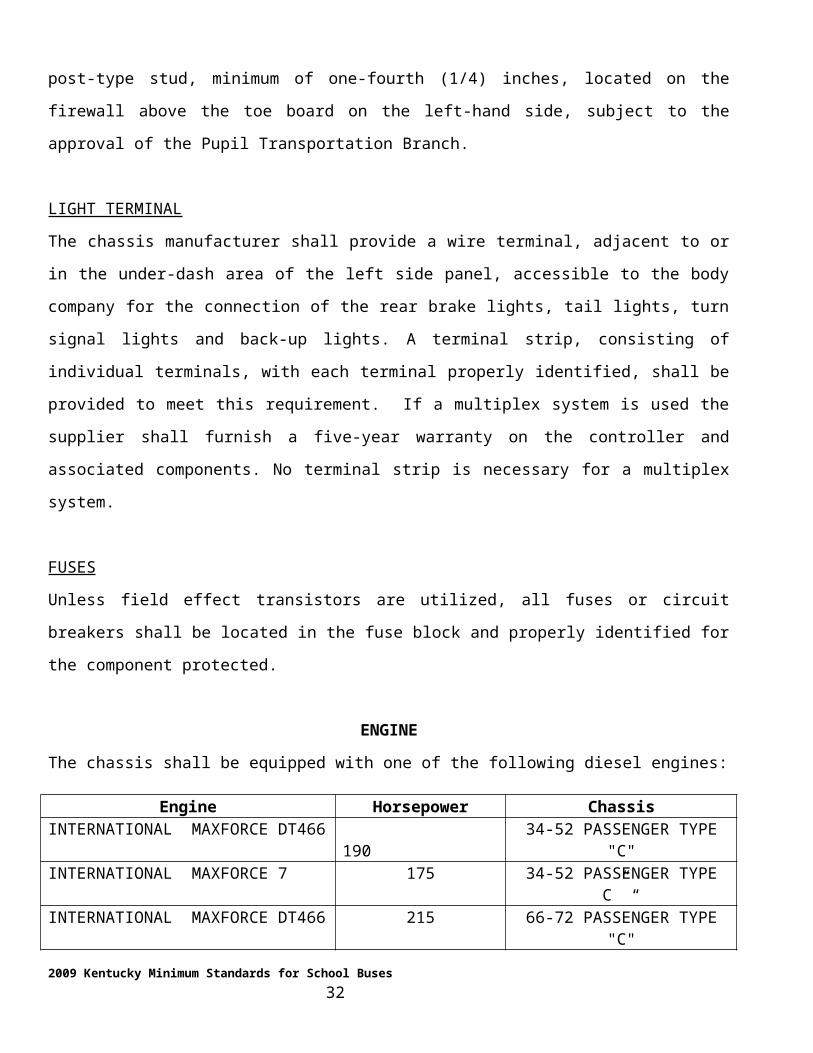
ENGINE
The chassis shall be equipped with one of the following diesel engines:
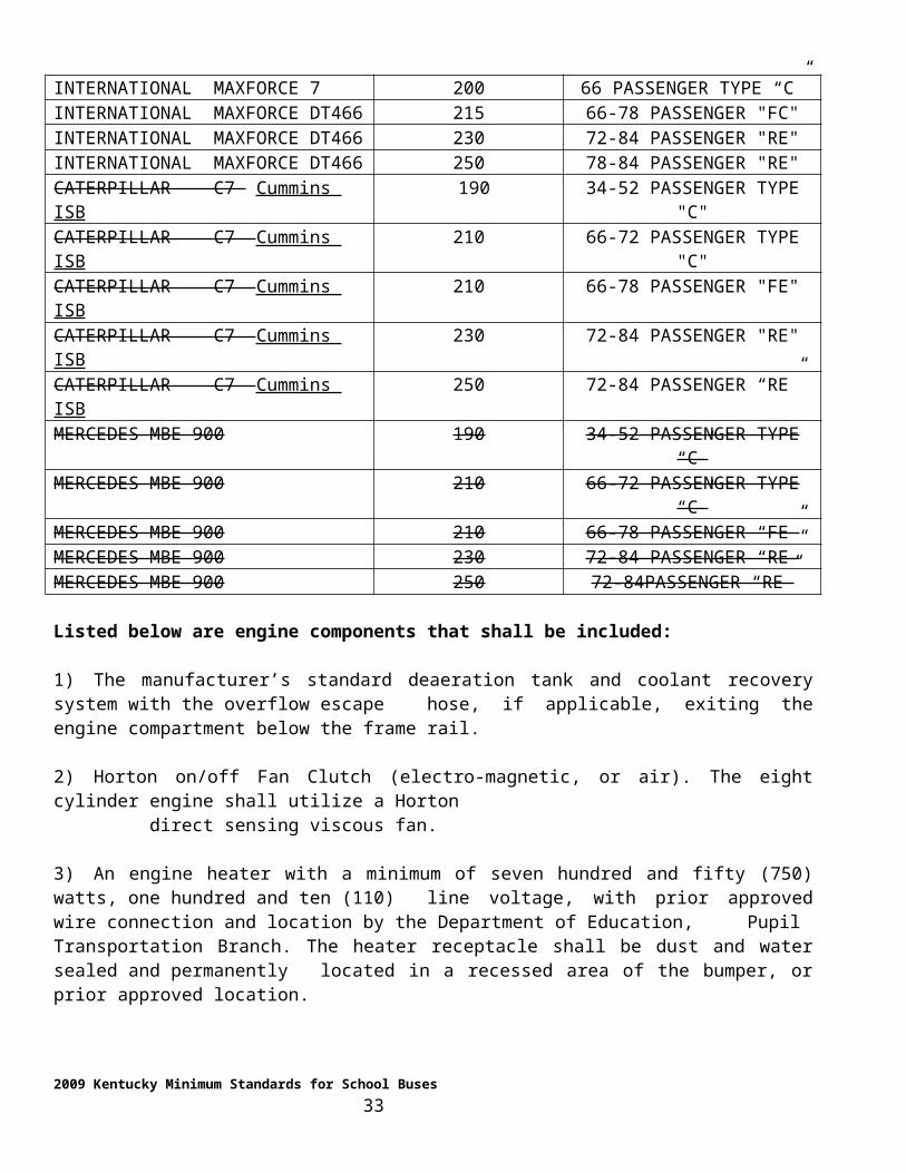
Engine Horsepower ChassisINTERNATIONAL MAXFORCE DT466 190 34-52 PASSENGER TYPE "C"INTERNATIONAL MAXFORCE 7 175 34-52 PASSENGER TYPE C” “INTERNATIONAL MAXFORCE DT466 215 66-72 PASSENGER TYPE "C"INTERNATIONAL MAXFORCE 7 200 66 PASSENGER TYPE “C”INTERNATIONAL MAXFORCE DT466 215 66-78 PASSENGER "FC"INTERNATIONAL MAXFORCE DT466 230 72-84 PASSENGER "RE"INTERNATIONAL MAXFORCE DT466 250 78-84 PASSENGER "RE"CATERPILLAR C7 Cummins ISB 190 34-52 PASSENGER TYPE "C"CATERPILLAR C7 Cummins ISB 210 66-72 PASSENGER TYPE "C"CATERPILLAR C7 Cummins ISB 210 66-78 PASSENGER "FE"CATERPILLAR C7 Cummins ISB 230 72-84 PASSENGER "RE"CATERPILLAR C7 Cummins ISB 250 72-84 PASSENGER “RE”MERCEDES MBE 900 190 34-52 PASSENGER TYPE “C”MERCEDES MBE 900 210 66-72 PASSENGER TYPE “C”MERCEDES MBE 900 210 66-78 PASSENGER “FE”MERCEDES MBE 900 230 72-84 PASSENGER “RE”MERCEDES MBE 900 250 72-84PASSENGER “RE”
Listed below are engine components that shall be included:
1) The manufacturer’s standard deaeration tank and coolant recovery system with the overflow escape hose, if applicable, exiting the engine compartment below the frame rail.
2) Horton on/off Fan Clutch (electro-magnetic, or air). The eight cylinder engine shall utilize a Horton direct sensing viscous fan.
3) An engine heater with a minimum of seven hundred and fifty (750) watts, one hundred and ten (110) line voltage, with prior approved wire connection and location by the Department of Education, Pupil Transportation Branch. The heater receptacle shall be dust and water sealed and permanently located in a recessed area of the bumper, or prior approved location.
4) The oil filter shall be a minimum two (2) quart capacity. (1.79 quart net capacity)
2009 Kentucky Minimum Standards for School Buses 23
5) A primary fuel filter and water separator, located between the tank and engine transfer pump. The filter shall be OEM installed and approved
6) Filter shall be Racor Model 330, thirty (30) micron spin-on, Racor Model 490, thirty (30) micron spin on or prior approved equal. The Pupil Transportation Branch at the pilot inspection shall approve the location.
7) If the fuel system includes a fuel return line to the tank, a secondary fuel filtration, in addition to the Racor Model 330 thirty (30) micron, shall be the manufacturer’s standard for engine protection.
8) Fuel system check valve shall be installed on the engine side of the fuel line exiting the fuel filter.
9) The engine shall be equipped with an electronic hand throttle. The throttle shall have no reference to cruise control and shall be marked "Throttle – High/Low". The hand throttle shall automatically return to idle when the service brake is depressed.
10) Corrosion-resistant metal hose bibs (sized for one inch ID heater hose), accessible to the body company for heater installation, shall be installed. Hose bibs, necessary plumbing, and indexing of plumbing shall require prior approval
11) Engine coolant hoses, requiring clamp connection one (1) inch and larger on the engine or associated components , shall be equipped with a Breeze constant torque clamp, Mubea constant tension clamp or prior approved equal.
NOTE: ALL ENGINES SHALL HAVE THE CAPABILITY OF PROVIDING A MINIMUM FREE WATER FLOW OF THREE (3) GALLONS PER MINUTE AT ONE HUNDRED AND SEVENTY (170) DEGREE TEMPERATURES AT ONE THOUSAND (1,000) ENGINE RPM FOR BUS HEATER OPERATION.
12) The engine housing cover and/or school bus body frontal area shall be so designed to provide reasonable access to the engine area for inspection and maintenance needs for fluid levels, belt tension, hose, wiring and other requirements as necessary. Type D Front Engine buses shall provide a prop rod or hook and cable device to hold the cover in an upright position during driver maintenance. The engine cover shall be sealed to prevent air intrusion into the passenger area.
13) The radiator shall be of welded tube to header design. Modine Beta Weld or Behr high frequency welded aluminum or approved equal.
EXHAUST SYSTEM
A total exhaust system, exhaust pipe, muffler and tailpipe shall be furnished by the chassis manufacturer, all routing to or through the bumper shall be manufactures standard for rear exhaust evacuation. The system shall be warranted for five years. If a manual regeneration mode is included in the system the control for the start of this system shall be designed or located to be accessible to a technician but not the driver.
2009 Kentucky Minimum Standards for School Buses 24
FENDERS (FRONT)
The total spread of the outer edges of the front fenders, measured at fender line, shall exceed the total
spread of the front tires when the front wheels are in a straight-ahead position.
FIRE WALL
The chassis manufacturer shall provide a clear area on the right and left side of the firewall to facilitate the
body company routing and location of the heater hose, heater valves and bulkhead fittings. It shall be the
responsibility of the chassis manufacturer to work with the body company and provide documentation of
location requirements prior to the bid award.
NOTE: ANY ADDITIONAL COST TO THE BODY MANUFACTURER AS A RESULT OF THE CHASSIS MANUFACTURER FAILING TO ADVISE AND PROVIDE DOCUMENTATION SHALL BE BORNE BY THE CHASSIS MANUFACTURER.
FRAME
The Type "C" school bus frame rating shall equal or exceed the gross axle weight ratings. The frame side
members shall be non-tapered and of one-piece construction. Extensions of the frame are permissible only
when such alterations are behind the rear spring hanger and shall not be for the purpose of extending the
wheelbase. Alterations shall be guaranteed by either the chassis or the body manufacturer whichever
makes the extension. There shall be no welding to the frame side rails except by the chassis or body
manufacturer and approved by the Pupil Transportation Branch. Frame rails shall be painted to avoid
corrosion.
Type "D" FC school bus frames shall be a minimum fifty thousand (50,000) PSI rated, full straight
channel aft of centerline of the front axle.
NOTE: NO ITEMS INSTALLED BY THE CHASSIS MANUFACTURER SHALL EXTEND ABOVE THE TOP OF THE FRAME RAILS. ANY ITEM INSTALLED CLOSE TO THE TOP OF THE FRAME RAILS SHALL BE FAR ENOUGH BELOW THEM TO PERMIT REASONABLE ACCESS FOR SERVICE OF SAID ITEM. ANY ITEM INSTALLED ON THE FRAME RAILS SHALL NOT EXTEND CLOSER TO THE GROUND THAN EIGHTEEN (18) INCHES UNLESS POSITIONED IN A LOCATION TO ENSURE THAT THE BREAK OVER ANGLES RELATIVE TO APPROACH AND DEPARTURE WILL PROVIDE FOR EQUIVALENT GROUND CLEARANCE.
TYPE "D" RE 78-84 PASSENGER MAIN FRAME SHALL BE A CONTINUOUS SECTION FROM THE FRONT OF THE VEHICLE TO AFT OF THE REAR SUSPENSION
2009 Kentucky Minimum Standards for School Buses 25
COMPONENTS WITH INNER LINERS. THE FRAME SHALL HAVE A MINIMUM RBM OF 850,000 INCH POUNDS. THE "C” CHANNEL INSERT SHALL EXTEND FROM THE REAR OF THE MAIN FRAME TO A POINT FORWARD OF THE REAR SUSPENSION MOUNTING POINTS.
FRAME LENGTHS
The length of the chassis frame and other chassis dimensions shall not be less than the minimum in the
following table:
CHASSIS PASSENGERCAPACITY
WHEEL BASE LENGTH(Inches)
COWL TO CENTER LINE
OF REAR AXLE (Inches)
COWL TO END OF FRAME(Inches)
CENTER LINE OF REAR AXLE
TO END OF FRAME (Inches)
MAXIMUM EXTENSION ALLOWED
(Inches)34 167 – 170 145 25152 215 – 218 192 29566 273–279 250 368
72 C 273-279 250 41966 FC 193 (MIN)
70-78 FC 228 (MIN) 138 2272-84 RE (MANUFACTURER’S STANDARD)
NOTE: EXCEPTIONS MAY BE ALLOWED TO THE CRITICAL DIMENSIONS STATED IN THIS TABLE (ONLY) WHEN THE SCHOOL BUS BODY AND CHASSIS IS BEING FURNISHED IN TOTAL BY THE SCHOOL BUS BODY MANUFACTURER.
FRAMES, WHICH ARE REQUIRED TO BE LENGTHENED BY THE BODY MANUFACTURER, SHALL BE LENGTHENED WITH FRAME MATERIAL EQUAL IN TENSILE STRENGTH AND BENDING MOMENT AS THE FRAME TO WHICH THE EXTENSION IS BEING APPLIED. ALL FRAME LENGTH EXTENSIONS SHALL BE WELDED AND/OR ATTACHED THROUGH A PROCEDURE APPROVED BY THE ORIGINAL CHASSIS MANUFACTURER.
FUEL TANK
Fuel tanks on fifty two (52) through seventy-eight (78) passenger chassis shall have, as standard, a
minimum capacity of sixty (60) gallons. The fuel tank on thirty-four (34) passenger chassis shall have a
minimum capacity of thirty (30) gallons. The thirty (30) and sixty (60) gallon fuel tanks shall have a
permanent non-corrosive inner lining. The tank shall be located on the chassis right frame rail for Type
"C" school buses. All fuel tanks shall contain baffles to prevent excessive sloshing of fuel.
Type "C” and “D” school buses shall require the tank to be in the manufacturers standard location, subject
to the approval of the Pupil Transportation Branch. Type "D" RE shall provide a one hundred (100) gallon
fuel tank. The section where the filler neck passes through the plane of the floor shall be constructed of a
minimum fourteen (14) gauge sheet metal, shall meet 60% joint strength with mechanical fasteners and
2009 Kentucky Minimum Standards for School Buses 26
shall be sealed and shall have an anti-spill design to minimize spillage in the event of body and chassis
separation, roll over, or the body shifting forward on the frame rails.
The engine supply line shall be taken from the top of the tank at a location toward the center of the tank.
The fuel tank, fittings or lines shall not extend above the top of the chassis frame rail. The drain plug, at
least one-fourth (1/4") in diameter, shall be located in the bottom of the tank. Fuel tank vents shall be
equipped with fuel resistant hoses, terminating and secured in an accessible location, subject to the
approval of the Pupil Transportation Branch.
FUEL SENDER
The chassis manufacturer shall provide the respective body company and the Pupil Transportation Branch
with fuel tank drawings, showing the location of the top tank fuel-sending unit.
GROSS VEHICLE WEIGHT RATING
The chassis shall have a GROSS VEHICLE WEIGHT RATING of the following minimums:
Type Chassis (Passenger Capacity) Gross Axle Weight (Pounds)
"C" 34 21,000
"C" 52 25,500
"C" 66-72 29,000
"D" FC 66-78 30,000
"D" RE 78-84 35,000
HOOD
Conventional chassis, thirty-four (34) through sixty-six (66) passenger buses, shall be equipped with a
forward tilting, fiberglass hood. The effort required to open the hood shall not exceed twenty-five pounds
when measured by pulling the handle at an angle parallel to the frame rails. The hood shall be painted with
school bus yellow paint. Standard school bus yellow paint may not be retrofitted on older model buses
(non reflective paint is required on all pre-2005 buses). The grille color shall be of the manufacturer’s
standard. (Paint shall be lead-free.)
2009 Kentucky Minimum Standards for School Buses 27
NOTE: CHASSIS MANUFACTURERS SHALL BE REQUIRED TO DEMONSTRATE THEIR ABILITY TO BRACE AND MAINTAIN THE HOOD AND COWL FIT FROM THE TIME OF THE CHASSIS MANUFACTURE THROUGH THE INSTALLATION OF THE BODY PRIOR TO THE BID AWARD.
HORNS
Each bus shall be equipped with dual electric horns. Each individual horn shall be installed to meet the
performance requirement of SAE J377, independently. The horns shall be installed in a way that will
minimize water intrusion.
INSTRUMENTS AND INSTRUMENT PANEL
The chassis instrument panel shall be equipped with the following:
1. Speedometer2. Odometer3. Voltmeter4. Oil pressure gauge5. Water temperature gauge6. Water temperature light/buzzer7. Fuel gauge8. Upper beam headlight indicator9. Turn signal indicator lights10. Air gauge (chassis with straight air brakes)11. Red light to indicate low air pressure12. FMVSS 105 indicator lights13. Tachometer (manufacturer’s standard - located in the instrument panel)14. Hour meter (located in the instrument panel and switched to operate only when engine is
running)
The above mentioned instruments shall be mounted in the instrument panel in such a manner that each
instrument is clearly visible for drivers ranging from the fifty (50) percentile adult female to the ninety-
five (95) percentile adult male, sitting in the normal seating position, as defined by SAE. Instrument
panels shall be sealed to protect from moisture intrusion during transport to the body manufacture and
shall be warranted for five (5) years by the chassis manufacturer. Instruments shall be accessible for
maintenance and repair. Instruments and controls shall illuminate for night use, controlled by the headlight
rheostat. Rear engine buses shall have oil pressure, water temperature, and voltmeter gauges located in the
engine compartment.
2009 Kentucky Minimum Standards for School Buses 28
AUDIBLE ALARMS.
The chassis manufacturer shall be responsible for providing audible alarms, significantly different tone or
interval, for over temperature, low air pressure and low oil pressure. The chassis manufacturers shall
furnish all bus body companies with audible alarm sound information so that the body companies may
install audible alarm systems of a different tone.
LIGHTS
The chassis shall be equipped with halogen headlights and a dimmer switch. The dimmer switch location
shall require prior approval of the Pupil Transportation Branch. School bus chassis of all pupil capacities
shall be equipped with Class "A" turn signals (front). Type "C" school buses shall have fender-mounted,
combination double-faced, turn signals with marker lamps with amber lens in front and red lens in rear,
and marker lamps on the side. Daytime running light shall be standard. Amperage draw shall not exceed
six amps.
OPENINGS
All openings in the floor, firewall or dash panel area shall be sealed.
REFLECTORS
Reflectors, meeting FMVSS 108, shall be installed on all front fenders.
SHOCK ABSORBERS
Chassis shall be equipped with front and rear, heavy-duty, double-acting shock absorbers.
SPRINGS (FRONT-REAR)
Each front and rear spring shall have a capacity, at the ground, of the minimums/maximums shown below:
Type Chassis (Passenger Capacity)
Front Minimum(Pounds)
Rear Minimum (Pounds)
Rear Maximum (Pounds)
"C" 34 4,000 6,500 6,500
"C" 52 4,000 8,750
"C" 66-72 5,000 9,250
"D" FC 66-78 7,000 9,250
"D" RE 78-84 6,500 11,500
2009 Kentucky Minimum Standards for School Buses 29
NOTE: IN NO CASE SHALL THE FRONT SPRING SUSPENSION HAVE A CAPACITY AT GROUND LESS THAN STATED ABOVE. COMPONENTRY, CAUSING USE OF HIGHER WEIGHT RATED AXLES, SHALL HAVE THE SPRING SUSPENSION ADJUSTED ACCORDINGLY (REFER TO "AXLES" SECTION, PAGES 1-2).
SPRINGS (REAR)
Air spring suspension shall be installed on all thirty-four (34) through eighty-four (84) passenger chassis.
NOTE: AIR SPRING SUSPENSION SHALL BE EQUIPPED WITH A SINGLE HEIGHT CONTROL VALVE. THE TRIM HEIGHT SHALL EQUATE TO THE SPRING TRIM HEIGHT WHEN THE AIRBAG IS INFLATED TO THE MANUFACTURER’S RECOMMENDED INFLATION RATE.
STEERING COLUMN (WHEEL)
All Type "C" and "D" buses shall be equipped with a manufacturer’s standard tilt adjustable steering
column.
STEERING MECHANISM
All school bus chassis, in all passenger capacities, shall be equipped with heavy-duty, truck-type, Ross
integral, power steering gear or prior approved equal. Power steering components shall be compatible with
the GVW rating for each capacity.
NOTE: THE DESIGN STEERING EFFORT SHALL NOT EXCEED APPROXIMATELY SEVENTY (70) INCH POUNDS AS MEASURED FROM THE CENTER LINE OF THE STEERING COLUMN.
TIRES AND RIMS
Tires supplied on all Kentucky school bus chassis shall be first-line, steel belted, low profile and tubeless
with highway-type tread, supplied by one of the major tire manufacturers under its own brand name and
furnished as original equipment as shown in the chassis supplier’s most recent data book and
specifications literature on file with the Pupil Transportation Branch. The tires shall be of the same
manufacture and tread design wheels. The tires shall be Goodyear 295/75R22.5 G169, General
295/75R22.5, Michelin 275/80R22.5 XZE, Bridgestone/Firestone 295/75R22.5 or prior approved equal.
All tires, rims and wheels shall be balanced by the chassis manufacturer. Any tire not balance, correctable,
with less than twenty (20) ounces of weight, shall be replaced. All tires shall be evaluated by the pre-
2009 Kentucky Minimum Standards for School Buses 30
delivery servicing dealer by means of road testing. Any tire found to be out of balance at the time of the
testing shall be corrected one hundred percent (100%) by the pre-delivery servicing dealer. All tires and
rims shall meet or exceed the minimums in the following table, with the rim rating capable of exceeding
the maximum tire inflation pressure.
CHASSIS CAPACITY TIRE SIZE LOAD RANGE RIM SIZE
TYPE "C"34-52-66 PASSENGER
275/80R22.5 G 8.25295/75R22.5 G 8.25
TYPE "D" FC70-78 PASSENGER
275/80R22.5 H 8.25295/75R22.5 H 8.25
TYPE "D" RE72-84 PASSENGER
275/80R22.5 H 8.25295/75R22.5 H 8.25
NOTE: ALL TIRES ON A GIVEN VEHICLE SHALL BE OF THE SAME BRAND, SIZE AND LOAD RATING. RIMS SHALL PROVIDE A RIM BEAD SEAT COMPATIBLE WITH LOW PROFILE TIRES. THE MAXIMUM TIRE INFLATION PRESSURE SHALL NOT ALLOW THE TIRE RATING TO EXCEED THE RIM RATING.
NOTE: A 34 PASSENGER (SHELL SIZE) FLAT FLOOR SPECIAL NEEDS BUS MAY HAVE 245/70R/19.5, LR G TIRES ON 7.5’ RIMS OR APPROVED EQUAL.
TRANSMISSION (AUTOMATIC)
Chassis, thirty-four (34) through eighty-four (84) passenger capacity, equipped with spring-loaded rear
axle parking brakes, may be purchased with an automatic transmission.
The automatic transmission shift quadrant shall be dash mounted and located to the right of the steering
column, accessible to the driver and approved by the Pupil Transportation Branch. The gearshift quadrant
shall be covered by a scabbard and lighted, with provision for a backup and neutral safety switch and a
positive lock shift with the reverse position forward.
Buses equipped with 3000 PTS transmissions may utilize a touch pad shifting mechanism. All 2500 series
transmissions shall be equipped with an Allison approved cable controlled scabbard shift. All Allison
automatics shall be filled with TransSynd fluid or prior approved equal.
The following engines shall be equipped with the following automatic transmissions:
Engine Horsepower Capacity Transmission Standard/Option
INTERNATIONAL DT466E 190 34-52 PTS2500 STANDARDINTERNATIONAL DT466E 215 66 PTS2500 STANDARD
2009 Kentucky Minimum Standards for School Buses 31
Engine Horsepower Capacity Transmission Standard/Option
INTERNATIONAL DT466E 215 66 PTS3000 OPTIONINTERNATIONAL DT466E 215 72-C PTS3000 STANDARDINTERNATIONAL DT466E 215 66-78 FC PTS3000 STANDARDINTERNATIONAL DT466E 230-250 72-84 RE PTS3000 STANDARDCAT – C-7 Cummins ISB 190 34-52 PTS2500 STANDARDCAT – C-7 Cummins ISB 210 66 PTS2500 STANDARDCAT – C-7 Cummins ISB 210 66 PTS3000 OPTIONCAT – C-7 Cummins ISB 210 72-C PTS3000 STANDARDCAT – C-7 Cummins ISB 210 66–78 FC PTS3000 STANDARDCAT – C-7 Cummins ISB 230-250 72-84 RE PTS3000 STANDARDMERCEDES MBE 900 190 34-52 PTS2500 STANDARDMERCEDES MBE 900 210 66 PTS2500 STANDARDMERCEDES MBE 900 230 66 PTS3000 OPTIONMERCEDES MBE 900 230 72-C PTS3000 STANDARDMERCEDES MBE 900 230 66-78 FC PTS3000 STANDARDMERCEDES MBE 900 230-250 72-84 RE PTS3000 STANDARD
Transmissions shall be equipped with an automatic backup light switch. The chassis manufacturer shall
be responsible for matching the transmission ratios, with respective engines within design parameters of
the school bus operation.
WARRANTY
Chassis warranties shall be the manufacturer’s standard, twelve thousand (12,000) miles or twelve (12)
months. Any chassis or chassis component warranty extension greater than standard warranty coverage
shall be made available to purchasers. THE IN-SERVICE DATE OF THE CHASSIS WARRANTY
SHALL BE STATED AS PART OF THE INVITATION TO BID ON KENTUCKY SCHOOL BUSES.
(Normally August 15) One copy of the chassis/body manufacturer’s bus warranty and service handbook
shall be shipped to each purchasing school district.
All engine drive train (Engine, Transmission, Differential and Drivelines) warranties shall be a minimum
five-year unlimited miles with one hundred (100) percent parts and labor.
WHEELS
Dual wheels shall be provided on the rear axle. Wheels shall be disk-type. The spacing for dual wheels
shall be the manufacturer’s recommendation for snow chain usage. The wheel hub drum system shall be
hub-piloted, single nut, ten (10) bolt, ISO system and shall have outboard mounted drums for all thirty-
four (34) through eighty-four (84) passenger school bus chassis.
WHEEL ALIGNMENT
2009 Kentucky Minimum Standards for School Buses 32
All steering axles shall have a toe-in set to provide for a zero inch (0") toe-in under a normally loaded
school bus axle in a normal driving mode.
Unladened axles shall have toe-in preset to one thirty-second (1/32) inches +/- one thirty-second (1/32")
inch.
NOTE: SHOULD THE TIRE (GOODYEAR, CONTINENTAL/GENERAL, MICHELIN AND/OR BRIDGESTONE/FIRESTONE) AND CHASSIS MANUFACTURERS JOINTLY DETERMINE AND CERTIFY A TOE-IN REQUIREMENT OTHER THAN THE REQUIREMENT REFERENCED BY THE ABOVE MENTIONED STANDARD AS THE OPTIMUM SETTING FOR DRIVABILITY, MANEUVERABILITY AND LONGETIVITY, THE ABOVE MENTIONED STANDARD WILL ADJUST ACCORDINGLY.
2009 Kentucky Minimum Standards for School Buses 33
SECTION 1PART 2
SCHOOL BUS SPECIFICATIONS
THE SPECIFICATIONS IN THIS SECTION APPLY TO TYPE "C" CONVENTIONAL SCHOOL BUS BODIES WITH A RATED PUPIL CAPACITY OF THIRTY-FOUR (34) THROUGH SEVENTY-TWO (72) AND ARE GENERAL SPECIFICATIONS FOR TYPE “A” SIXTEEN (16) AND TWENTY-TWO (22) PASSENGER AND TYPE “D” SIXTY-SIX (66) THROUGH EIGHTY-FOUR (84) PASSENGER SCHOOL BUSES.
ACCESSORY COMPARTMENT (DRIVER)
The school bus body manufacturers shall equip all bus bodies with a driver accessory compartment
enclosure, which has a cover for containment of articles. The cover shall be securely closed by a positive
action latch designed to avoid injury if impacted. The location of the accessory compartment shall be
subject to the approval of the Pupil Transportation Branch. The compartment size shall provide a
minimum six hundred sixty (660) cubic inches and be designed to hold a ten (10) by twelve (12) by two
(2) inch, three ring binder.
BACK-UP ALARM
A back-up alarm shall be installed on all school buses. The back-up alarm shall meet SAE Standard J994,
Type B 107 db. The back-up alarm shall be securely fastened to the bus with the location determined by
the Pupil Transportation Branch at the pilot inspection and shall have an individual ground wire as close
as possible to the component. The back-up alarm shall be switched on automatically through the chassis
back-up light switch. All wiring shall meet SAE Standards and exceed capacity rating by twenty-five (25)
percent, protected by a fuse with routing and connections and consistent with recognized automotive
wiring practices. Back-up alarms shall be rearward of the engine on Type "D" rear engine buses.
ANTIFREEZE
The bus body company shall replenish the cooling system and fill the body heater system with extended
life coolant TELC ASTM 4785 or fully formulated, ethylene glycol, long life diesel coolant ASTM D5345
and D-6210. Antifreeze type and additives shall meet the requirements of the respective engine
manufacturers and radiator suppliers. The additive levels, when required, shall be recorded by the
2009 Kentucky Minimum Standards for School Buses 34
company performing the pre-delivery service. Prior evidence that antifreeze meets the respective
manufacturer’s recommendation must be furnished.
NOTE:AN EXTENDED LIFE ANTIFREEZE DECAL SHALL BE APPLIED IN THE VICINITY OF THE RADIATOR FILL NECK AND OVERFLOW BOTTLE FILL AND SHALL STATE THE TYPE OF ANTIFREEZE TO BE UTILIZED.
BATTERY
All batteries shall be installed in a battery box or sliding tray with a door. A battery hold down bracket
shall be designed for clamping action around all four sides of the battery. All chassis will be equipped
with three (3) batteries. The battery box shall be labeled with one-inch (1") letters. The bracket shall be
designed for three (3) "Group 31" batteries and secured to the sliding tray with a minimum of two (2) tie-
down bolts. Battery conductors entering the battery compartment shall be securely clamped to eliminate
cable abrasion. (Brackets not allowing forward or lateral movement of the battery tray will not be
acceptable.) Type "D" chassis manufacturers shall provide for the battery location, meeting the above
mentioned performance requirements and shall coordinate with the respective body manufacturer and the
Department of Education, Pupil Transportation Branch, for approval of location.
NOTE: BATTERY BOX SHALL BE LIMITED TO BATTERY, CABLES AND ASSOCIATED WIRING. BODY COMPANIES SHALL NOT INSTALL RELAYS, BREAKERS OR SOLENOIDS INSIDE THE BATTERY BOX.
BODY FLUID CLEAN-UP KIT
Each bus shall be equipped with a body fluid clean-up kit, containing;
1. Nitrel rubber gloves;
2. An eye shield and face mask;
3. A germicidal towel effective against TB and HIV;
4. A germicidal, disposable cloth;
5. Chlorinated absorbent beads;
6. A disposable gown, and
7. A biohazard disposal bag.
The body fluid clean-up kit shall be located on the right front crash barrier lower panel on the left front
crash barrier behind the driver’s seat or in the overhead storage bin. The body fluid clean-up kit shall be
secured off of the floor, in a hat-shaped bracket, hemmed on all edges, designated to secure the kit on all
sides and be able to sustain a 20G load in any direction except upward. The assembly shall be designed to
2009 Kentucky Minimum Standards for School Buses 35
minimize the risk of snagging clothing. If stored overhead, the location shall be labeled in one-inch block
letters.
NOTE: BODY FLUID CLEAN-UP KIT COMPONENTS SHALL BE PACKAGED IN A METAL, DUST-PROOF CONTAINER.
BUMPER (FRONT)
Type "D" front bumpers shall be one piece, a minimum of three-sixteenths (3/16) inches plate steel, nine
and one-half (9 ½) inches high, frame mounted, die formed (minimum 14 inches blank), with a ninety (90)
degrees flange top and bottom. Front bumpers shall be so designed and formed to equate in strength in the
frontal and quarter loading, as compared to the strength of one-fourth (1/4) inches front bumper installed
by OEM on conventional school buses. The bumper shall be painted black. The front bumper shall be
designed and installed so that it will be capable of supporting the weight of the front of the vehicle during
towing or when being lifted by a jack.
NOTE: TYPE "D" (FC, RE) BUSES SHALL BE EQUIPPED WITH A SKIDPLATE, DESIGNED TO PROTECT THE STEPWELL FROM FRONTAL IMPACT AS WOULD BE EXPERIENCED WHEN GOING OVER A CURB OR DROPPING THE RIGHT FRONT WHEEL OFF OF THE PAVEMENT.
BUMPER (REAR)
Type "C" and Type "D" rear bumpers shall be steel channel, a minimum of three-sixteenths (3/16) inches
in thickness, nine and one-half inches (9½) inches wide, constructed to wrap around rear corners,
extending forward a minimum of twelve (12) inches.
Bumper construction and attachments shall be designed to protect from corner or side impact, mounted for
ease of removal and positioned to close openings between the bumper and body. Type "D" RE seventy-
eight (78) through eighty-four (84) passenger school buses shall be equipped with front and rear tow
hooks.
All bumper end caps shall be fully enclosed. Any bumper to body opening shall be closed with trim
material. The bumper shall extend at least one (1) inch beyond the rearmost part of the body surface,
measured at floor line. The bumper shall be painted black.
2009 Kentucky Minimum Standards for School Buses 36
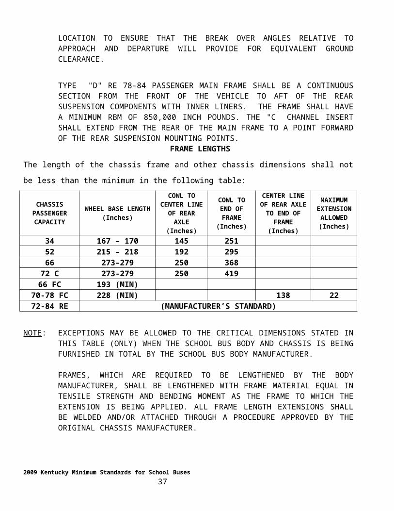
CEILING
The interior of the bus body shall be free of all unnecessary projections likely to cause injury. This
standard requires an inner lining on the ceiling and walls. Ceiling panels may be perforated.
COLOR
The outside of the school bus body, excluding those components painted by the chassis manufacturer,
shall be painted with lead-free primer and polyurethane surface coat. The surface coat shall be “National
School Bus Chrome (yellow) " in accordance with the colorimetric specifications of Federal Standard
595A, Color 13432. The roof of the school bus shall be painted with lead-free primer and white
polyurethane surface coat. White paint shall extend to within six (6) inches above the drip rails on the side
of the body except that the front and rear roof caps shall remain National School Bus Yellow.
The interior of the school bus body shall be painted the manufactures standard color (white, off white,
light gray) with a lead-free primer and surface coat.
EXCEPTION: THE LOWER INTERIOR BODY PANELS (BELOW THE WINDOW AREAS)
MAY BE THE MANUFACTURER’S STANDARD CLEAR COAT OR BRIGHT COAT
ALUMINIZED STEEL). THE MANUFACTURER SHALL BE REQUIRED TO FURNISH TEST
DATA EQUATING ANY SIDE PANEL FINISH TO THE PAINT FINISH (PRIOR TO
INSTALLATION) IN TERMS OF DURABILITY AND CORROSION PROTECTION.
CONSTRUCTION
Bus body construction shall be of prime-commercial quality mill-applied galvanized steel, galvalume or a
type of metal or material equal in strength and non-rust qualities to mill-applied galvanized steel. All such
construction materials shall be fire-resistant. Any material proposed as equal to galvanized steel must have
prior written approval from the Pupil Transportation Branch before being installed or fabricated into the
school bus body. If roof caps are constructed of fiberglass, the fiberglass must be backed with a steel
inner liner to protect the passenger compartment.
The floor shall be of prime commercial quality mill-applied, galvanized steel or galvalume of at least
fourteen (14) gauge.
2009 Kentucky Minimum Standards for School Buses 37
ROOF STRAINERS
Two (2) or more roof strainers, or longitudinal members, shall connect roof bows, space roof bows and
reinforce roof skin. The strainers shall extend from the windshield header to the rear header.
SIDE STRAINERS
There shall be one (1) or more side strainers, or longitudinal members, connecting vertical structural
members to prevent impact and resist penetration in the event of contact with other vehicles or objects.
The strainer(s) shall be formed from metal minimum sixteen (16) gauge and shall be installed in the area
between the bottom of the window and the bottom of the seat frame, extending completely around the bus
body except for the door openings and the body cowl panel. The strainer(s) shall be fastened to each
vertical structural member.
REAR CORNER REINFORCEMENTS
Rear corner framing of the bus body between the floor and window sill and between the emergency door
posts and last side posts shall consist of at least three (3) structural members, applied horizontally or
vertically or in another combination, to provide additional impact and resist penetration equal to that
provided by the frame members in the areas of the sides of the body. Such structural members shall be
securely attached at each end.
FLOOR SILLS
All floor sills shall be of prime commercial quality, mill-applied galvanized or galvalume steel. There
shall be one (1) main body sill at each side post and two (2) intermediate body sills on approximately ten-
inch (10") centers. All sills shall be of equal height not to exceed three (3) inches. All sills shall extend the
width of the body floor except where structural members or features restrict the area. The main body sill
shall be equivalent to or heavier than ten (10) gauge and each intermediate body sill shall be equivalent to
or heavier than sixteen (16) gauge, or each of all of the body sills shall be equivalent to or greater than
fourteen (14) gauge. All sills shall be permanently attached to the floor. Connection between the sides and
the floor system shall be capable of distributing loads from vertical posts to all floor sills.
INTERIOR PANELS
All interior panels shall be designed so that the rear panels are lapping over the front panels. All exposed
edges of the interior panels, including the shoulder rails and light bars, shall be hemmed; the design of
light bars shall be provided so that there will be no separation of a lapped panel joint from a side impact.
2009 Kentucky Minimum Standards for School Buses 38
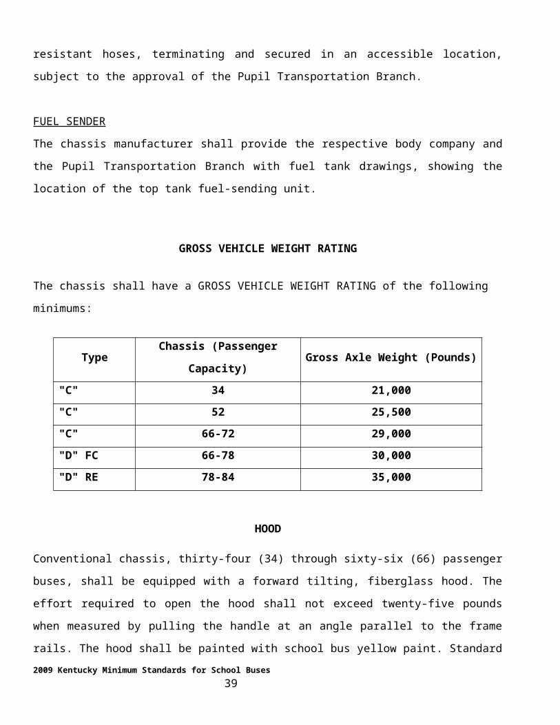
As evidence of the above, the body shall be impacted at any point along the roof line on the outside
surface, using an eight (8) inch diameter cylinder, forty-eight (48) inches long at a thirty (30) to forty-five
(45) degree angle, one (1) to three (3) inches above the top window line. The cylinder shall impact the
roofline with the forty-eight (48) inches dimension in a vertical plane with a force not to exceed ten (10)
inches maximum to eight (8) inches minimum penetration of the body panels into the passenger
compartment after impact.
NOTE: INTRUSION TESTS PERFORMED, UNDER PROTOCOL ESTABLISHED IN KENTUCKY MINIMUM SPECIFICATION FOR SCHOOL BUSES, REVISED 1991, AND CERTIFICATION THEREOF, SHALL MEET THE REQUIREMENTS FOR CERTIFICATION UNDER THIS STANDARD UNLESS SIGNIFICANT CHANGES TO THE BODY CONSTRUCTION HAVE OCCURRED.
ROOF CONSTRUCTION
Mechanical fasteners shall be used in all roof panel joints to achieve sixty (60) percent joint strength.
Construction adhesive will not be permitted to meet the joint strength requirements. All roof sheets shall
be sealed with Ruvan or approved equal. The product supplier shall certify that recommended practice is
being followed. Manufactures utilizing structural adhesives along with mechanical fasteners (hybrid
joints) to achieve compliance with FMVSS 221 shall be capable of demonstrating to the Kentucky
Department of Education that the design of the hybrid joint in conjunction with the adhesive and
mechanical fasteners used is capable of 150% of FMVSS 221 strength test.
FLOOR CONSTRUCTION
All body floor joints shall be fastened to meet sixty (60) percent joint strength. The body floor in the toe
board area shall be designed to mate to the chassis toe board area without the use of structural transition
panels unless the structural transition panels meet sixty (60) percent joint strength at the point of
attachment of the body floor and/or super structure. Cutouts for the transmission opening shall be covered
by the original transmission cover supplied by the chassis manufacturer without extension flanges.
SIDE CONSTRUCTION INTEGRITY
School bus body sides shall be so constructed that there will be no separation of construction joints or a
lapped panel separation from a side impact. Body sides shall be so constructed to withstand an intrusion
force of twenty thousand (20,000) pounds minimum.
2009 Kentucky Minimum Standards for School Buses 39
As evidence of the above, the body shall be impacted at a point of twenty-four (24") plus or minus two (2)
inches above the floor line, with an eight (8) to ten (10) inch diameter cylinder, forty-eight (48) inches
long, mounted in a horizontal plane. The cylinder shall impact the body side, spanning two (2) roof posts
in a body side area, having interior lapped panels with a force not to exceed a maximum of ten (10) inches
to eight (8) inches minimum penetration of the body side into the passenger compartment after impact.
Body companies shall furnish to the Pupil Transportation Branch certification of the test performance;
showing the body side, window header, and floor line deformation of a body side, consisting of a
minimum of seven (7) body sections with the impact test performed on a center line of the seven (7) body
sections. The impact test for the body shall be complete in structure with seats installed on the impact side.
Body companies performing an intrusion test as part of the certification document shall include the
amount of force required for penetration relative to the compliance standard.
OPENINGS
The body manufacturer shall seal all openings between the chassis and passenger-carrying compartment.
DOORS – SERVICE DOOR (FRONT ENTRANCE DOOR)
Service doors for Type "A", Type "C" and Type "D" school buses shall be outward opening. All buses
equipped with air brakes shall have air-operated or electric doors. Door operation and construction
integrity shall require approval of the Pupil Transportation Branch. The service door shall be located on
the right side of the bus, opposite the driver within his/her direct view. This door shall be operated under
the control of the driver. It shall be so designed as to afford easy release and to prevent accidental
opening. All door parts, with particular reference to closing edges, shall be designed so as to minimize the
possibility of crushing or shearing the body and/or hand extremities.
CRITICAL DIMENSIONS
The service door shall have a minimum horizontal opening of twenty-four inches (24") and a minimum
vertical opening of sixty-eight (68) inches. The bottom of the lower glass panel shall not be more than
thirty-five (35) inches from the ground when the bus is unloaded. The top of the upper glass panel shall
not be more than six (6) inches from the top of the door. The vertical closing edges shall be equipped with
a flexible material to protect children’s fingers.
2009 Kentucky Minimum Standards for School Buses 40
DOOR OPERATOR (MANUAL)
The door opening and closing mechanism shall be a pivot device such as Cleveland 2321-A or approved
equal. This device shall have sufficient hand leverage to open and close the door with ease. Door
operators shall be equipped with a positive latch device to retain the door in a closed position. The latch
shall be so designed to provide ease of release by the bus driver through one hand operation while opening
the door. It shall also be equipped with a pressure switch to operate the step well light. The entrance door
operator and control rods shall be plated or otherwise treated to prevent rusting and corrosion.
DOOR OPERATOR (AIR or ELECTRIC)
The air-operated door shall meet all of the requirements of the manual-operated door with regard to the
door type and folding design. This door shall be capable of being operated by a single three (3) position
sequential switch, located to the left of the driver in a convenient and accessible spot, subject to the
approval of the Pupil Transportation Branch. The first position shall activate the red flashing lights and the
stop arm with the door closed; the second position shall open the door; returning the switch to the off
position shall close the door and cancel the stop arm and red lights. The amber lights shall be controlled
by a manual button located on the control panel to the left of the driver. Controls shall be a sequential
operating system. If electrically operated, the system shall be designed to de-mesh the gears when de-
energized.
PROTECTION
An air pressure valve shall be required for the protection of the air brake system in which air shall be
drawn from the supply tank, in accordance with FMVSS 121 and shall be located as per the requirements
of the respective chassis body builder’s manual. The body company shall supply an air pressure regulator
for air supply to the slave cylinder that will ensure the regulated air supply not to exceed the designated
regulator setting. The body company shall supply a means to control the door closure and opening speed.
The force required to achieve the door closure shall be a maximum of sixty five (65) pounds prior to and
through the door achieving the closing plane. The door closure force shall be so constructed to minimize
the occurrence of injury to persons caught in the area while in a door closing mode. The door shall be so
designed to provide for manual opening in the absence of air pressure or electrical current for energizing
without further action by the driver, such as manually off-loading the cylinder or de-meshing the gears.
Type "C" school buses equipped with air brakes systems shall be equipped with air-operated doors as
standard equipment. Type "D" school buses shall be equipped with a power operator door as standard
2009 Kentucky Minimum Standards for School Buses 41
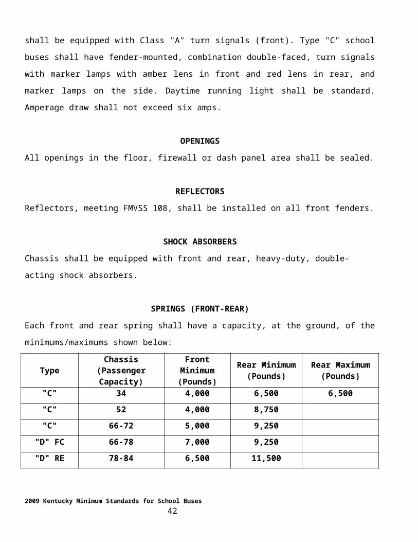
equipment. Power door operators that are approved as equal to air door operators require prior approval
from the Pupil Transportation Branch.
NOTE: APPROVAL SHALL REQUIRE ENGINEERING DATA, DOCUMENTING ADEQUATE PROTECTION OF THE POWER SOURCE AND STUDENT SAFEGUARDING THROUGH POWER REDUCTION AT THE DOOR OPENING WHICH WOULD EQUATE TO FORCES IMPOSED BY A MANUAL OPERATOR.
HEAD BUMPER PAD (ENTRANCE DOOR, EMERGENCY DOOR SIDE AND REAR)
There shall be a head bumper pad installed on the inside door header. This bumper pad shall be
approximately three (3) inches in width and shall extend across the entire width of the entrance door
opening. The head bumper shall be padded a minimum of one-half (1/2) inch foam, covered with the same
upholstery material as covering the seats. The upholstery shall enclose all sides and ends. Exposed screws
shall be installed with counter sunk finish washers or other means to protect the riders from impacts.
When the head bumper pad mount is used to enclose door retention hardware the cover over the hardware
shall be capable of supporting a 120 lb weight when dropped from a height of four (4) feet. The weight
shall be attached to the cover at a single point.
EMERGENCY DOOR (REAR)
The upper portion of the emergency door shall be equipped with approved safety glass. The exposed area
shall not be less than four hundred (400) square inches. The lower portion of the emergency door shall be
equipped with approved ASA laminated glass. The exposed area shall be approximately three hundred and
fifty (350) square inches.
The words "EMERGENCY DOOR, " both inside and out, in letters at least two (2) inches high, shall be
installed. The lettering shall be a premium quality six (6) mill fleet grade reflective film with a minimum
of six (6) year outdoor durability (Reflexite or 3M). The decal shall have a film background, "National
School Bus Chrome (yellow) " in color, and light reflective with black lettering. The decal shall meet the
performance requirements and reflectance measurements no less than those set forth in Federal
Specification L-S300C. The decal shall be placed directly above the emergency door, on the door in the
metal panel above the top glass area.
The emergency door shall be designed so as to open from inside and outside the bus and shall be equipped
with a fastening device that may be quickly released but designed to offer protection against accidental
2009 Kentucky Minimum Standards for School Buses 42
release. Control from the driver’s seat shall not be permitted. The provision for opening from the outside
shall consist of a non-detachable device so designed to prevent the capability of hitching to but to permit
opening when necessary. The emergency door hinge pins shall be made of brass or approved equal. All
hinges shall be equipped with threaded grease fittings.
The emergency door opening at floor level shall be constructed to provide a recessed seal. No seal
extending above the floor line will be acceptable. The emergency door shall be held open in accordance
with FMVSS 217, and shall be subject to the approval of the Pupil Transportation Branch at the pilot
inspection. Door hinges shall have threaded grease fittings or an enclosed hinge designed to resist
corrosion.
EMERGENCY DOOR LATCH
The emergency door shall be equipped with a slide-bar, cam-operated lock. The slide bar shall have a
minimum stroke of one (1) inch. The emergency door lock shall be equipped with a suitable electric
plunger-type switch, connected with a buzzer located in the driver’s compartment. The switch shall be so
installed that the plunger, contacts the outer edge of the slide bar in such a manner that any movement of
the slide bar will immediately close circuit on the switch and activate the buzzer. The switch shall be
properly located and adequately protected from damage when securing the door latch. The door lock shall
be equipped with an interior handle that extends approximately to the center of the emergency door. It
shall lift up to release the lock. The handle of this latching device shall be of sufficient length to permit a
small child to open the emergency door and shall be painted red.
The latch handle shall be protected by a steel shield of adequate width to prevent the handle from being
actuated by a child falling against the emergency door. This guard shield shall have sufficient clearance
above the latch handle to permit easy grasp of the handle. If the handle is not easy to grasp a door pull
shall be installed that will allow the full hand to be used for pulling the door closed.
Operating instructions detailing the emergency door shall be applied on the inside of the emergency door.
If the latch handle on the outside of the emergency door is not located on the extreme left-hand side of the
emergency door, a door pull, open at the bottom end to prevent hitching onto, shall be affixed in the
2009 Kentucky Minimum Standards for School Buses 43
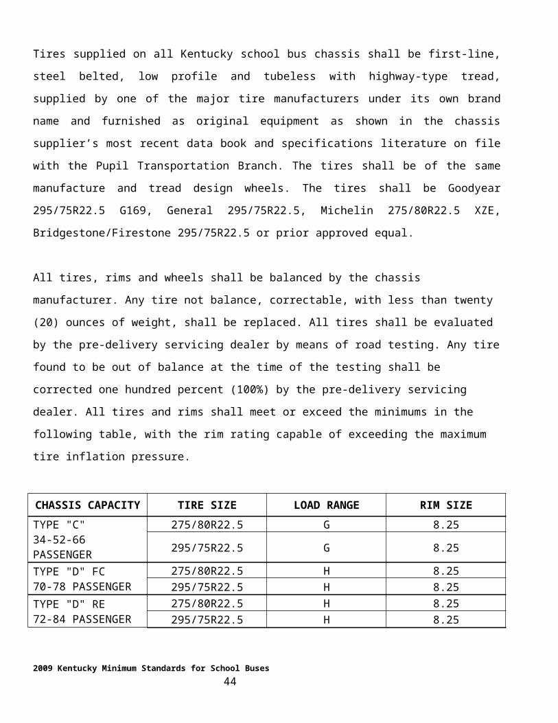
extreme left-hand location. This emergency door pull shall be constructed of heavy metal and shall be free
from any sharp edges like to cause injury.
NOTE: TYPE "D" RE SHALL UTILIZE A REAR EMERGENCY WINDOW TO MEET THE ABOVE REQUIREMENT.
EMERGENCY DOOR (LEFT SIDE)
Left Side Emergency Door Location
School bus body shells, of sixty (60) passenger capacity and larger, shall be equipped with a left side
emergency door, installed approximately mid-ship between the last row of seats and the restrain barrier
behind the driver’s seat.
AISLE AND STAGING AREA
The school bus body manufacturer shall provide a minimum twelve (12) inch wide aisle from the center
aisle of the school bus to the left side emergency door and shall provide a twenty-four (24) inch wide
staging area in front of the left side emergency door, pursuant to the requirements set forth in the FMVSS
for the rear emergency door. Flip-up seats will not be accepted.
OCCUPANT PROTECTION
The school bus body manufacturer shall provide for occupant protection as required by FMVSS 222 for
all passengers fore, aft and adjacent to the emergency door location.
FLOOR PLAN
The school bus body manufacturer shall submit floor plans at the time bid quotations are submitted
showing the:
1. Location of the left side emergency door;
2. Aisle and staging area; and the
3. Seating plan depicting the load for each body shell size in which a left side door is
installed.
TESTING PROCEDURE
1. Apply a seventeen thousand (17,000) pound force to a designated area of the school bus side,
including a left side emergency door, to determine if that force will cause a deflection amount
greater than ten (10) inches inward.
2009 Kentucky Minimum Standards for School Buses 44
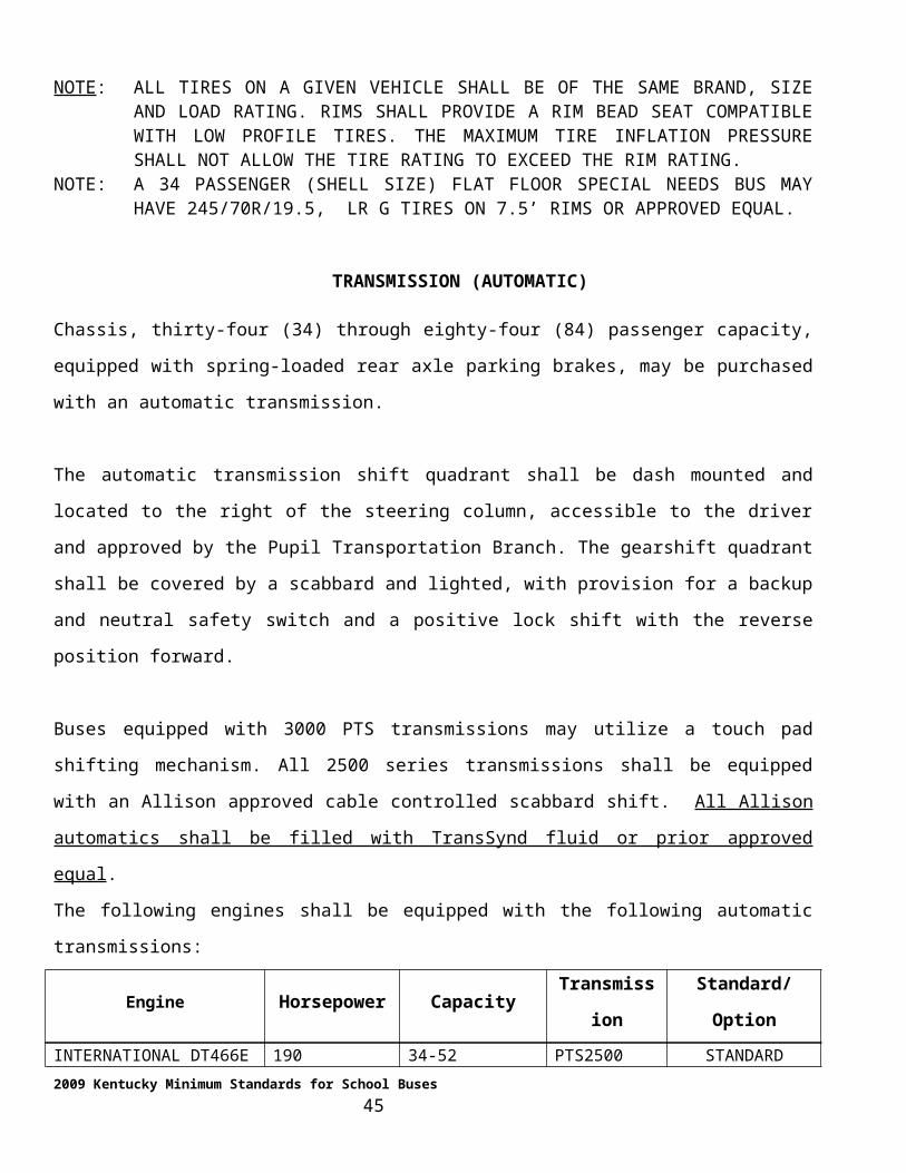
2. Door retention hardware must be capable of withstanding an outward force of five thousand two
hundred and eighty (5,280) pounds before the side intrusion test and five thousand two hundred and
eighty (5,280) pounds after, through a distance of less than ten (10) inches with twenty thousand
(20,000) pounds of intrusion force applied. The top and bottom latching bars shall be enclosed in
such a fashion as to prevent their being used as a handle upon exit. Such installation will be subject
to Pupil Transportation Branch inspection.
3. All body sides adjacent to the passenger seating positions shall be required to withstand the above
mentioned intrusion force, relative to the amount of deflection.
4. The left side emergency door, when installed, shall have an adjacent body structure so designed that
the side body structure shall withstand the above-mentioned intrusion, relative to the amount of
deflection. The left side emergency door shall be secured with a three (3) point latching mechanism.
CERTIFICATION
The body company manufacturers shall certify that all school bus bodies having a left side emergency
door installed meet the above requirements, by:
1. Performing intrusion tests, as referenced, with regard to the cylinder size and location;
2. Performing intrusion tests by placing the center point of the test cylinder so that, in a
horizontal position, it aligns with the vertical centerline of the emergency door and the ends of the
test cylinder span the emergency doorpost. When the intrusion test is being performed on a school
bus body side, the school bus body shall be complete with passenger seats and restraint barriers
properly positioned;
3. Applying a uniform force of five thousand two hundred and eighty (5,280) pounds to the
left side emergency door retention hardware both before and after the side intrusion testing
(certification shall require that the door retention hardware does not release or deform when the test
is applied).
NOTE: THIS STANDARD IS IN ADDITION TO THE SIDE CONSTRUCTION STANDARD PERFORMED ON THE RIGHT SIDE AS EXPLAINED PREVIOUSLY.
EMERGENCY ROOF EXITS/VENTS
The sixteen (16) through eighty-four (84) passenger school bus bodies shall be equipped with emergency
roof exits/vents.
2009 Kentucky Minimum Standards for School Buses 45
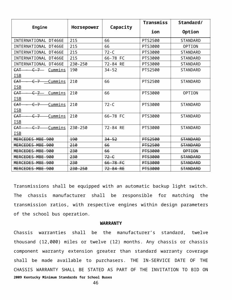
The sixteen (16) through fifty-two (52) passenger school bus bodies shall be equipped with one
emergency roof exit/vent as near as practical to the midpoint of the passenger compartment, on the
approximate centerline of the school bus roof. The sixty-six (66) through eighty-four (84) passenger
school bus bodies shall be equipped with two (2) emergency roof exits/vents, one located as near as
practical to a point equal distant between the midpoint of the passenger compartment and the foremost
limit of the, first and last row of seats. Installation shall require the approximate location on the centerline
at a midpoint between the middle and front row of seats and the middle and last rows of seats. Roof hatch
openings shall be boxed on three (3) sides by bow stringers or other stiffeners in addition to the roof sheet.
NOTE: SHOULD THE BODY CONSTRUCTION NOT ALLOW FOR THE PLACEMENT OF THE EXITS/VENTS AS MENTIONED, AN ALTERNATE LOCATION SHALL REQUIRE WRITTEN APPROVAL OF THE PUPIL TRANSPORTATION BRANCH.
The installation of the emergency roof exits/vents shall be performed in such a manner that will not cause
removal or cutting of any roof structural component. The roof exits/vents shall be equipped with an
outside release and alarm switch. This alarm switch shall be wired to an audible signal located in the
driver compartment. Emergency roof exits/vents shall be, Transpec 1175 Triple Value Series.
Roof hatches shall have one (1) inch National School Bus Yellow reflective tape applied around the
perimeter not more than six (6) inches from the mounting base applied to the roof sheets.
ELECTRICAL SYSTEM
WIRING
All school bus body wiring shall conform to the "Standards of the Society of Automotive Engineers"; all
ground studs shall meet three (3) wire standard ASE J1908-9.3 ground stud criteria, coded for
identification, with amperage rating of twenty-five (25) percent greater than the designed load. The body
company shall provide and clearly identify two positive leads and two grounding points for the connection
of two way radios and video cameras. These circuits shall operate at all times that the key is in the on
position and shall be capable of carrying 20 amps.
Each individual body circuit shall have overload protection that may be accomplished by fuses, circuit
breakers or field effect transistors. If fuses are used they must be labeled. Fuse blocks, fuses, and circuit
breakers shall require prior approval of the Pupil Transportation Branch. All circuit wiring shall be
2009 Kentucky Minimum Standards for School Buses 46
covered by a convoluted loom, through a raceway and be protected by grommets when passing through
body members.
All wiring harnesses shall be securely fastened at close intervals. All wiring splices shall be soldered and
joint-insulated or machine crimped.
WIRING DIAGRAM
A wiring diagram, illustrating all body wiring circuitry, shall be provided with each school bus body. This
wiring diagram shall be specific to the wiring on a Kentucky specified bus and shall be included in the
repair manual.
LIGHT TERMINAL
The chassis manufacturer shall provide a wire terminal in the under-dash area of the left side panel,
accessible to the body company for the connection of the rear brake lights, taillights, turn signal lights and
back-up lights (refer to Section 1, Part 1). The body company is to utilize this terminal for the connection
for lights.
All body electrical loads, controlled by the accessory side of the headlight switch, shall be through a relay.
All body electrical loads on the headlight side of the switch causing a switch load of seventy-five (75)
percent or greater than the switch design shall be through a relay.
This wiring is to be arranged in at least these circuits:
1. Step well, clearance and identification lamps, stop lamps, combination stop and tail lamps
through a relay controlled by the headlight switch
2. Dome lamps
3. Audible alarms on the emergency door, push-out windows and roof hatches (Body
companies shall be required to provide audible alarms significantly tone different than those audible
alarms provided as original equipment on chassis component systems.)
4. Turn signal lamps.
5. Flashing red warning lamp, to be combined with #7
6. Stop arm-flashing lamps, to be combined with #6 crossing gate
7. Emergency override switch to red flashing lamps and stop arm
2009 Kentucky Minimum Standards for School Buses 47
8. Heaters and defrosters
9. Auxiliary fans.
10. Electrical windshield wipers
11. Electric windshield washers
12. Ignition circuit to the body solenoid shall be fused
13. Noise suppression solenoid
SOLENOID SWITCH
The bus body electrical system shall be equipped with a continuous-duty solenoid switch of adequate
capacity to handle the body electrical load. This solenoid switch shall be energized by the ignition switch
in either the accessory or run position and shall cut off the electrical power from all bus body circuits
when the ignition switch is in the "OFF" position, except to those body circuits that are energized by a
chassis switch provided by the chassis supplier. This solenoid switch is to be a one hundred (100) AMP
continuous-duty White-Rogers 124-105-211 or prior approved equal. The body feed wire shall be
connected to the chassis terminal post and shall have a minimum current carrying capacity of one hundred
twenty-five (125) amperes, continuous (four-gauge minimum).
NOISE SUPPRESSION SWITCH
All Kentucky school buses shall include a “Noise Suppression Switch” within easy access of the driver.
The Switch shall turn off noise producing accessories to include heater blowers, defroster fans, auxiliary
fans and radios if so equipped. The system shall include a switch and solenoid. The label may be
abbreviated “Noise Supp”.
FOUR WAY FLASHER SWITCH
A separate four way flasher switch shall be located adjacent to the noise suppression switch .to allow a
driver to activate/de-activate both switches simultaneously or individually. The switch shall be labeled
“Four-way Flasher”.
ELECTRICAL ACCESSORY CONTROL PANEL AND DASH PANEL
An enclosed electrical accessory panel or panels shall be installed to the left of the driver’s seat. The
required accessory switches shall be located on this panel or panels. The accessory control or switch panel
shall have an adequate means for lighting all of the switches and the accessory controls. On Type "D"
2009 Kentucky Minimum Standards for School Buses 48
school buses which have the dash panel installed by the body manufacturer, switches, gauges, and lights
shall be designed and positioned to be readily accessible from the driver seat and provide for reasonable
accessibility for maintenance. Proposed instrument panel shall be submitted at the Pre-bid Award
Conference. Switch positions should approximate the order contained in Appendix III. Some variance
from this standard in expected. We expect the following rules to be applied. All passenger-loading
controls shall be located within the span of an average drivers hand defined as a circle having a radius of
four (4) inches. These controls shall include; momentary switch, door control switch, noise suppression
switch, crossing gate override, and eight-way override. All passenger comfort switches shall be located as
close as practical to each other. This group shall include; heaters, defrosters, auxiliary fans and strobe
light. Defrosters shall be located closest to the dash. Heaters shall be located according to their position
in the bus. (I.E. drivers heater before mid-ship before rear heater) Infrequently used controls such as
mirrors shall constitute a separate group.
NOTE: IF TOTAL LOAD ON TAIL LIGHT SWITCH EXCEEDS 10 AMPS, A RELAY SHALL BE INSTALLED. IF THE ELECTRICAL LOAD OF THE ACCESSORY SIDE OF THE HEADLIGHT SWITCH EXCEEDS SEVENTY FIVE PERCENT OF THE CONTINUOUS DUTY CAPACITY OF THE ACCESSORY SIDE OF THE HEADLIGHT SWITCH, THOSE CIRCUITS SHALL BE SWITCHED BY MEANS OF A RELAY ENERGIZED BY THE HEADLIGHT SWITCH.
TOTAL ELECTRICAL LOAD
The total constant electrical load shall not exceed one hundred (100) amps.
NOTE: THE TOTAL CONSTANT ELECTRICAL LOAD IS TO BE COMPUTED AS THE CONSTANT LOAD, PLUS THIRTY-FIVE PERCENT (35%) OF THE INTERMITTENT LOAD. THE INTERMITTENT LOAD SHALL INCLUDE ONLY THESE ITEMS:
Back up alarm Turn signal lamps (4) Stop lamps (4) Back-up lamps (2) Step well lamp Domes (8) Warning lamps (8) – (8) lamp system Stop arm Heated mirrors (2) Wipers, radio
ENGINE HOUSING COVER (TYPE "D" FC SCHOOL BUSES)
2009 Kentucky Minimum Standards for School Buses 49
The interior engine housing cover shall be easily removable without the use of special tools to the
proximity of the floor and shall provide access to the engine components. This cover may be made in two
(2) parts, can be removed in sections for maintenance and be contoured as necessary to provide for ease of
entrance and egress. The cover shall have sufficient strength to allow a driver to stand on it without
damage. The cover shall have a prop rod or a cable devise to hold the cover in the open position during
maintenance.
The engine compartment on the Type "D" RE shall be insulated with a thermal sound barrier sandwiched
between panels. This insulation shall provide protection from heat and noise generated by the engine.
FANS (AUXILIARY)
A body header mounted squirrel cage type fan, or approved equal, shall be installed on thirty-four (34)
through eighty-four (84) passenger buses. This system shall be equipped with automotive type louvers
that can be directed toward the driver. A single auxiliary fan shall be added to the left of the driver located
to provide maximum windshield coverage. This Auxiliary fan shall be a heavy duty type, six inch (6”)
blades and caged with a small mesh corrosion-resistant metal guard.
FIRE EXTINGUISHER
The fire extinguisher shall be Amerex 3A-40BC, Model 443 or prior approved equal. Approved equals
must be of identical weight and dimensions as the Amerex. The bracket shall be provided by the
extinguisher manufacturer. It shall be designed for school bus use, provide for easy removal and have
retention capabilities to withstand substantial impact (3,000-pound sled impacted into body at any angle at
thirty (30) miles per hour). Retention clamps and straps shall be designed and tested to perform without
loosing clamping capabilities for two hundred (200) applications. A fire extinguisher label shall be
applied in compliance with 45 CFR Part 1310, Head Start Transportation.
Fire extinguisher shall be located in a position that minimizes the chance of clothing getting snagged or
shall be covered with a durable shroud.
FIRST AID KIT
Each bus shall be equipped with a twenty-four (24) unit first-aid kit with the following contents:
2009 Kentucky Minimum Standards for School Buses 50
ITEM UNITS1" x 2 ½ yards adhesive tape rolls 23" x 3" sterile gauze pads 243/4" x 3" adhesive bandages 1002" bandage compress 83" bandage compress 102" x 6 ‘ sterile gauze roller bandages 2Non-sterile triangular bandages
(40" x 36" x 54" with safety pins)2
Sterile gauze pads 36" x 36" 3Sterile eye pads with tape 3Rounded-end scissors 1Nitrile gloves (pair) 1Mouth-to-mouth airway 1
FIRST-AID KIT LOCATION
The first-aid kit shall be located in a position that minimizes the chance of clothing becoming entangled.
This kit shall be secured off of the floor, in a "hat-shaped" bracket, hemmed on all edges, designed to
secure the kit on all sides and be able to sustain a 20G load in any direction except upward. The first-aid
kit shall have a label in compliance with 45 CFR Part 1310, Head Start Transportation.
NOTE: FIRST-AID KIT COMPONENTS SHALL BE PACKAGED IN A METAL DUST-PROOF CONTAINER. THE KIT SHALL BE EDCOR SAFETY MODEL 24M-SBK-91, CERTIFIED SAFETY MANUFACTURING MODEL 24M-SBK-94 OR PRIOR APPROVED EQUAL.
FLOOR
The floor and floor covering material shall have an opening cut over the fuel tank, in the area of the fuel-
sending unit, to allow the removal of the fuel-sending unit. This opening shall be sealed and covered by a
metal plate that is attached to the flooring with metal screws.
FLOOR COVERING
The floor covering material, excluding wheel well covers and the entrance step well, shall be fire-retardant
material. School bus body manufacturers shall have tested and certified that the floor covering materials
will not ignite, in either a horizontal or vertical plane by utilizing the Boston Bag Burn Test by the date of
the Pre-Bid Award Conference. The test shall be conducted in a draft-free, three (3) sided, top-covered
enclosure, with the Boston Burn Bag Burn Test applied to two (2) foot wide by three (3) foot tall vertical
sample and a two (2) foot wide by two (2) foot long horizontal sample. Samples shall be tested in an L-
2009 Kentucky Minimum Standards for School Buses 51
shaped configuration, with the Boston Bag placed on the horizontal sample having the back resting against
the vertical sample center. Scorching of material will be permissible, provided the material does not ignite.
The floor of the school bus body, driver’s compartment and toe board area shall be covered, with a one-
eighth (1/8) inch minimum thickness, smooth finish floor covering material. This material shall be a top
quality, fire-resistant rubber floor covering or approved equal. It shall be blue swirl, RCA Rubber #TR-
702, or 2902-3902-713 (smooth), 3904-1202-713 (aisle) color coordinated with the body interior and
bonded with a water-resistant adhesive.
The aisle and entrance area shall be covered with material that has a corrugated or ribbed surface. Rubber
base floor covering for the aisle shall be three-sixteenth (3/16) inches thick. The depth of the corrugations
or ribs shall be sufficient to allow dirt and abrasive material to lie below foot level.
All floor seams shall be covered with a rust-resistant metal strip, adequately anchored to the floor. Any
floor covering seam or joint not covered by this trim material shall be properly mated and secured to the
deck with a water-resistant adhesive.
The landing area shall be covered with the same material used to cover the aisle. It shall have a nosing of
the same color contrast as the step covering material and extend back along the floor toward the aisle as
far as practicable to meet the aisle covering material and make a trip-proof joint away from the top of the
step. A metal seam cover at the step edge of the landing area will not be permitted. Floor covering
material in the driver’s area and body floor frontal area shall be secured to the deck with a water-resistant
adhesive. The adhesive-applied material shall run forward to the point of transition from the body floor to
the chassis toe board, unless restricted by certain design limitations. Exceptions will require prior approval
of the Pupil Transportation Branch.
STEP COVERING
Steps shall be covered with first quality, specially processed step covering material, Koroseal pebble top,
Blue #71 or RCA Rubber, Apex, Color #702 or approved equal. Step covering material shall have non-
skid characteristics. The step covering shall have a contrasting white, turndown nosing. The lip of the
turndown shall be molded in an approximate 90º shape and shall be an integral part of the tread. Pebble
pattern shall extend to the leading edge of the nosing on all but the top step and shall have corrosion and
impact resistant polymeric or galvanized metal backing.
2009 Kentucky Minimum Standards for School Buses 52
The step covering shall be securely fastened to the steps in a manner that will minimize tripping. This
requires that the heads of mounting screws or bolts be below the top surface of the step tread.
NOTE: ALL FLOOR COVERING SEAMS, JOINTS AND TERMINATION EDGES SHALL BE SEALED.
FLOOR PLAN
Buffer Zone
The floor plan, except as otherwise provided in these specifications, shall provide for a minimum twelve
(12) inch buffer zone behind the rear seat, between the rear interior wall, to be the full width of the seat
back as measured at the rear most portion of seat cushion frame.
NOTE: TYPE "D" RE BUSES DO NOT REQUIRE A REAR BUFFER ZONE.
Critical Dimensions - Wheelbase, Passenger Capacity, Rear Axle Overhang
School bus body shells shall be mounted on the following school bus chassis and shall meet the following
performance specification:
Minimum Wheelbase Passenger Capacity Maximum Rear Axle Overhang
Type “C”
167 inches 34 10 feet
215 inches 52 11 feet
273 inches 66 12 feet, 6 inches
273 inches 72 13 feet, 6 inches
Type “D” FC 228 inches
70 11 feet
74 12 feet, 6 inches
78 13 feet
Type “D” RE Shall be manufacturer’s standard
FUEL FILL COVER
The fuel fill opening in the body skirt shall be equipped with a spring loaded hinged cover held closed by
a driver positioned latch. This latch SHALL BE METAL and shall require prior approval.
2009 Kentucky Minimum Standards for School Buses 53
"DIESEL FUEL" shall be painted or decaled on or adjacent to the fuel fill access cover in approximately
one (1) inch black lettering.
GLASS
Openings in the school bus body that require glass must be closed with quality glazed ASA safety glass
that is a minimum one-eighth (1/8) inches thick.
The windshield shall be LAMINATED SAFETY GLASS ASA-1 with a minimum distortion. The
bottom portion of the rear emergency door shall be ASA LAMINATED SAFETY GLASS.
HEATERS
School bus heating systems shall meet the following performance standards:
A. Provide evenly distributed heat throughout the bus body.
B. Provide defrosting for the windshield and entrance door.
C. Have capabilities of providing evenly distributed heat, creating a temperature rise to 50 degrees Fahrenheit inside the body shell when soaked in an ambient temperature of 0 degrees Fahrenheit for fifteen (15) hours.
D. The heater water flow shall be controlled by the installation of bulkhead mounted water shutoff valves. (Water shutoff valves and bulkhead mounts shall require approval from the Pupil Transportation Branch. Refer to heater valve drawings of the appendix.)
E. Valves shall be one-quarter (¼) turn, ball-type, and have a minimum nominal three quarters (3/4) inch internal port.
F. The heater hose entrance through the firewall or floor shall be through prior approved bulkhead fittings.
G. Type C – FC buses shall have all drivers' heaters air duct extended beyond the drivers side modesty panel into the passengers area a minimum of four (4) feet.
H. Total heater electrical load, including defroster fans, shall be no more than forty-five (45) amperes.
I. Switching for heaters shall provide independent switches for each motor.
J. Type C and type D bus heaters shall have easily removable air filters. NOTE: ALL TYPE C AND D BUSES REQUIRE A STEP WELL HEATER OF A MINIMUM
50,000 BTU OUTPUT AS A PART OF THEIR TOTAL HEATER SYSTEM. THIS HEATER SYSTEM SHALL HAVE A DUCT LOUVERED TO BLOW DIRECTLY
2009 Kentucky Minimum Standards for School Buses 54
AGANST THE ENTRANCE DOOR GLASS AT THE LOWEST PRACTICLE POINT. THESE LOUVERS SHALL BE FIXED TO ENSURE THE CLEARANCE OF MOISTURE FROM THE LOWER GLASS.
Heater Hose and Clamps
The heater hose shall be one (1) inch inside diameter. The heater hose shall be Goodyear Hi-Miler, Gates
Blue Stripe or approved equal. All heater hose clamps shall be constant torque clamps. (Refer to the
"NOTE" in the "CHASSIS" section). Clamps shall be torqued to the manufacturer’s recommendation. The
hose between heaters shall be protected by a metal raceway or conduit.
NOTE: HEATER HOSES OF ANY DIAMETER OTHER THAN ONE INCH (1") INSIDE THE DIAMETER NECESSARY TO PROVIDE FOR PROPER FLOW DISTRIBUTION SHALL REQUIRE PRIOR APPROVAL OF THE PUPIL TRANSPORTATION BRANCH.
THE ENGINE MANUFACTURER SHALL BE RESPONSIBLE FOR THE INSTALLATION OF HOSE BIBS, ONE (1) INCH IN DIAMETER, ACCESSIBLE TO THE BODY COMPANY FOR THE ATTACHMENT BY THE BODY COMPANY.
Heater performance shall be measured by the following:
A temperature measurement that is taken thirty-nine (39) inches inward from side walls, thirty-nine (39)
inches inward from windshield and rear door, and thirty-six (36) inches above the floor. It shall include
measurements from the front, middle and rear of the bus. The heat shall be evenly distributed through the
aisle area.
The bus will be soaked at an ambient temperature of zero (0) degrees Fahrenheit for fifteen (15) hours.
The temperature must rise to 50 degrees Fahrenheit inside in twenty (20) minutes when one hundred and
seventy (170) degree water is applied at a rate of three (3) gallons per minute at a maximum of six (6) PSI
pressure.
NOTE: MAXIMUM CURRENT FLOW FOR HEATERS INCLUDING DEFROSTERS SHALL NOT EXCEED FORTY-FIVE (45) AMPERES.
Heater cores installed in Kentucky school buses shall meet the following test standard:
STATIC PRESSURE TEST 150 PSI
CYCLE TEST 20-50 PSI HYDRAULIC SURGE PRESSURE 450,000 CYCLES MINIMUM
2009 Kentucky Minimum Standards for School Buses 55
CORE FLOW RESTRICTION TOTAL HEATER SYSTEM FLOW RESTRICTION SHALL BE MEASURED AT A FLOW RATE OF THREE (3) GALLONS PER MINUTE AT A MAXIMUM OF SIX (6) PSI PRESSURE WHEN MEASURING HEATER PERFORMANCE.
A bleeder valve shall be installed in the highest point in the return line.
HEATER DEFROSTER
Defrosters shall be included in the total electrical load for heaters and meet the following criteria:
A. Capable of defrosting the total windshield area in a reasonable period of time under all normal driving conditions.
B. Shall provide means of defrosting service door glass independent of the windshield.C. Capable of mixing a minimum fifty (50) percent outside fresh air with defrosting air.D. System shall exceed the SAE standard J381-J382 performance requirement without the use of an
auxiliary fan and with three (3) gallons per minute one hundred seventy (170) degree water applied.
NOTE: ALL MANUFACTURERS SHALL DEMONSTRATE THE CAPABILITIES OF THEIR HEATING AND DEFROSTING SYSTEM PRIOR TO THE BID AWARD. COOLANT USED FOR HEATER SYSTEMS SHALL MEET ENGINE OEM SPECIFICATIONS.
INSIDE HEIGHT
The minimum inside body height shall be seventy-two (72) inches to seventy-eight (78) inches maximum,
measured at any point of the longitudinal centerline from the front vertical bow to the rear vertical bow.
INSULATION
The ceiling and all walls shall be insulated with fire resistant, underwriter-approved fiberglass insulation
or prior approved material having an "R" valve not less than six (6), a minimum thickness of one and one-
half (1½) inches. All voids, including those caused by roof bows and header caps, shall be insulated. Type
"D" school buses, having a frontal area designed by the body company manufacturer, shall require the
frontal area to be insulated with the insulation of a type approved by chassis and body manufacturers.
INTERIOR
The entire length of the joint between the floor covering and the wall of the school bus body shall be
covered with a curved, fitted, metal molding, making a tight seal between the floor covering and the wall.
All interior seams shall be sealed.
2009 Kentucky Minimum Standards for School Buses 56
LAMPS AND SIGNALS
CLEARANCE LAMPS
The body shall be equipped with armored clearance and mid-body lamps. These lamps shall be
manufactured by Grote, Weldon or Sound Off Inc., LED lamps, minimum of four (4) candlepower, or
prior approved equal. These lamps are to be mounted at the highest and widest position on the corners.
IDENTIFICATION LAMPS
Identification lamps shall be individually mounted, connected to the chassis headlight circuit and be
activated by the chassis headlight switch relay. Lamps shall be manufactured by Weldon, Grote or Sound
Off Inc LED lamps or prior approved equal.
BACK-UP LAMPS
The school bus body manufacturer shall install two (2) back-up lamps, located on the left and right rear of
the body as far outboard and as low as is practical. These back-up lights shall be Weldon, 2025-7100-30
Grote, Sound Off Signal L.E.D. lights or prior approved equal.
COMBINATION STOP AND TAIL LAMPS
The bus shall be equipped with two (2) combination stop and tail lamps, a diameter of not less than seven
inches (7"), with plain red lens emitting red light plainly visible from a distance of five hundred (500) feet
to the rear. These lamps shall be as high as practicable but below the window line and spaced as far apart
as practicable, no less than three (3) feet. Measurements shall be taken from the lamp centers. The
stoplights are to be activated by the brake switch. These lamps shall be Weldon, Grote, Sound Off, LED
lamps or prior approved equal. If these lamps are not round they must have a minimum of thirty eight
(38) square inches surface area.
FOUR-INCH STOP AND TAIL LAMPS
Each bus shall be equipped with two (2), four-inch combination stop and tail lamps. These lamps shall be
Weldon, Grote, or Sound Off LED lamps and shall be connected to the brake-operated stop lamp circuit.
LICENSE PLATE ILLUMINATOR
The license plate shall be illuminated in combination with the four-inch LED stop and tail lamps located
on the left rear or by a separate license plate illuminator provided that the illuminator is the body
manufacturer’s standard LED Lamp.
2009 Kentucky Minimum Standards for School Buses 57
INTERIOR LAMPS
Interior lamps to adequately illuminate the aisles and step well, shall be approved as follows: two (2)
lamps for each group of three (3) seat rows. These lights are to be located on both sides of the aisle and
shall be no closer to the center ceiling line than twelve (12) inches. The interior lamps are to be mounted
in a substantial lamp house, which shall be flange or screw-mounted to the body ceiling metal. The lens of
this lamp shall be held in by a flange. Screws or other substantial means not easily removed or operated by
the pupils shall be used to secure this light.
NOTE: LAMPS ON SPECIAL NEEDS BUSES SHALL BE EVENLY DISTRIBUTED
THORUGHOUT THE BUS IN EVERY OTHER ROOF SECTION, STARTING WITH THE
LIGHT IN THE REAR MOST PANEL.
STEP-WELL LIGHT
The step-well is to be equipped with an adequately protected automatic step-well light. This light shall be
activated by a switch in conjunction with the entrance door opening mechanism and wired so that the light
comes on when the entrance door is opened and the headlights are on.
OUTSIDE LANDING LIGHT
All school buses shall be equipped with a skirt-mounted exterior landing area light. The upper portion of
this light shall be shielded to cast light downward only. This light shall be Weldon Grote or Sound Off
LED lamp. (Wired through the headlight circuit)
EIGHT-LIGHT WARNING SYSTEM
The school bus body shall be equipped with a system of four (4) red LED signal lamps and four (4) amber
LED signal lamps. Each amber signal lamp shall be located near each red signal lamp, at the same level,
but closer to the vertical centerline of the bus. The system of the red and amber LED signal lamps shall be
wired so that the amber lamps are energized manually and the red lamps are automatically energized (with
the amber lamps being automatically de-energized) when the bus service door is open.
2009 Kentucky Minimum Standards for School Buses 58
All systems shall include a separately fused manual over ride system. Flashing lamps shall be Weldon.
Grote, Sound Off LED signal lamps or prior approved equal. The flasher device shall be Weldon 7000
with a flash rate of seventy (70) to seventy-five (75) c/p/m or prior approved equal. If a system controller
is utilized it shall be warranted for five (5) years. All eight-way light lenses shall be easily replaceable
using mechanical fasteners.
OPERATION OF WARNING LIGHT-STOP ARM SYSTEM
The location of the momentary switch is subject to the approval of the Pupil Transportation Branch. The
momentary switch shall be Cole Hersee 9238, or Eaton 53-5262 for manual operation, a yellow
momentary rocker switch or approved equal. The momentary switch and its operation shall be identified
by decal or lettering and should function as follows:
1. By depressing the manual push button, the amber pilot light and amber warning lights shall flash.
2. When the entrance door is moved toward the open position, the amber pilot and warning lights shall go off; the red pilot and warning lights shall flash.
3. The stop arm is automatically extended and the lights on the stop arm flash.
4. In closing the entrance door, all lights will go out and the stop arm retracts automatically.
5. By opening the entrance door without depressing the manual push button, no lights flash, and the stop arm does not extend.
6. With the entrance door open, depressing the manual push button, the red pilot and warning lights flash.
7. The stop arm is automatically extended and the lights on the stop arm flash.
Both the amber pilot light lens and the red pilot lens shall be approximately one-half (1/2) inches in
diameter if not included in the instrument cluster. Both manual and air-operated door systems shall meet
the requirement listed above (#1 - #7). These pilot lights shall be installed in a position to be approved the
Pupil Transportation Branch.
NOTE: THE ENTRANCE DOOR SWITCH THAT ACTIVATES THE RED LIGHTS IN THE EIGHT-LIGHT SYSTEM SHALL BE LOCATED IN A POSITION, OR SHALL BE PROTECTED BY A COVER OR GUARD, THAT WILL PREVENT THE LIKELIHOOD OF THIS SWITCH BEING ACTIVATED OR DEACTIVATED BY PUPILS BOARDING
2009 Kentucky Minimum Standards for School Buses 59
OR LEAVING THE BUS. THE DOOR SWITCHES SHALL BE MOUNTED TO THE LEFT OF THE DRIVER.
The emergency system for extending the stop arm and flashing the red warning lights on the bus body and
the stop arm shall be installed on each bus body.
NOTE: AN EMERGENCY OVERRIDE SWITCH SHALL BE INSTALLED IN THE BUS BODY ELECTRICAL ACCESSORY PANEL IN AN AREA ISOLATED FROM THE OTHER SWITCHES, WHERE POSSIBLE. THIS SWITCH SHALL BE INSTALLED BY A STANDARD SWITCH IDENTIFICATION OR DECAL WITH THE WORDS “WARNING LIGHTS” OR “EMERGENCY WARNING LIGHTS.” THIS SWITCH SHALL BE SEPARATELY FUSED.
INSTALLATION REQUIREMENTS
Each flashing signal lamp shall be mounted with its axis substantially parallel to the longitudinal axis of
the vehicle. The front and rear alternately flashing signal lamps shall be spaced as far to the left and right
of header as practicable, for and aft facing and grouped in a way to provide for the amber lights spaced as
far apart on the header as possible.
Vertical and lateral vision of the front and rear alternately flashing warning lights shall not be obstructed
by any part of the body or lamp house. LAMP HOODS WILL NOT BE ACCEPTED.
A square or rectangular area around the lens of each alternate flashing signal light and extending outward
approximately three (3) inches shall be painted black. In installations where there is no flat vertical portion
of the body immediately surrounding the entire lens of the lamp, a square or rectangular band of black
(approximately three inches wide) immediately below and to both sides of the lens, shall be painted on the
body or roof area against which signal light is seen from a distance of five hundred (500) feet along the
axis of the vehicle.
TURN SIGNALS (FRONT AND REAR)
Type "D" school buses shall be equipped with the manufacturer’s standard front turn signals with amber
lens and side turn signals.
The above-mentioned lamps shall require prior approval for the Pupil Transportation Branch. All school
bus bodies shall be equipped with two (2), seven-inch rear turn LED signal lamps. The lens of these lamps
2009 Kentucky Minimum Standards for School Buses 60
shall show an amber arrow, with the arrow on the right lamp pointing right and the arrow on the left
pointing left. Rear turn signal lamps shall be mounted as near the outer edge of the bus body as possible.
They shall be Weldon,Grote, Sound Off LED lamps or approved equal.
STOP SIGNAL ARM
Each school bus body shall be equipped with a stop arm meeting SAE Standard J1133. The location of the
stop arm requires prior approval form the Pupil Transportation Branch and shall be:
1. Air-operated, SMC 2900 or Transpec Model 6000 series with wind guard and high
intensity school decal or approved equal, or
2. Electric operated, SMC 5900 Transpec Model 6000 series with wind guard and high
intensity school decal or approved equal.
Air-operated stop arms shall be installed on all chassis equipped with air brakes. An air-operated or
electric-operated stop arm may be installed on all school bus chassis with hydraulic brakes.
AIR-OPERATED STOP ARM
The chassis manufacturer shall designate the air source location for stop arm activation. The chassis air
supply shall be protected by a pressure protection valve. This valve shall meet the chassis manufacturer’s
requirements. The pressure protection valve shall be installed by the body manufacturer.
ELECTRIC-OPERATED STOP ARM
Electric-operated stop arm installation requires the body manufacturer to install stop arm circuit protection
in the body’s fuse panel. All wiring shall be coded and sized to a minimum of one hundred and twenty-
five percent (125%) amperage rating and protected through all metal openings.
STOP ARM ACTIVATION
All stop arms and stop arm flashing lights are to be electro-mechanically activated when the red lights of
the eight-light warning system are on. This activation is to occur when the entrance door handle is moved
toward an open position or when used.
CROSSING CONTROL ARM
2009 Kentucky Minimum Standards for School Buses 61
1. Buses shall be equipped with a crossing control arm mounted on the right side of the front bumper, which shall not open more than ninety degrees. All air brake equipped chassis shall be equipped with air operated crossing arms.
2. All components of the crossing control arm and all connections shall be weather proofed.
3. The crossing control arm shall incorporate system connectors (electrical, or air) at the gate and shall be easily removable to allow for towing of the bus.
4. The crossing control arm shall be constructed of non-corrosive or nonferrous material.
5. There shall be no sharp edges or projections that could cause hazard or injury to students.
6. The crossing control arm shall extend approximately seventy inches from the front bumper when in the extended position.
7. The crossing control arm shall extend simultaneously with the stop arm(s) by means of the stop arm controls.
8. The tip of the arm shall be equipped with electro magnetic catch and or bracket unless integrated into the bumper and so constructed as to be firmly held when in the closed mode.
9. The system shall include a momentary cancel switch to prevent the arm from being deployed in tight quarters.
10. Crossing control arm shall be Specialty Manufacturing Company, 6 series solid state or prior approved equal for hydraulic brake buses.
11. If an air operated system is employed it shall require a dedicated solenoid valve and regulator (Specialty 2800 series air operated for all air brake chassis).
12. All crossing gate system components shall be warranted for two years, parts and labor.
DISABLED WARNING DEVICES
Three (3) triangular warning devices, housed in approved containers and secured in an approved location,
shall be provided. These devices shall meet the ICC and FMVSS requirement and shall be located, in the
drivers outside toolbox. The box shall be labeled "Triangle Reflectors Inside" secured with a metal band to
withstand a 20G load in any direction.
NOTE: WHEN THE BUS IS EQUIPPED WITH A FULL COMPLEMENT OF LUGGAGE BOXES, THE TOOL BOX SHALL BE DELETED AND THE DISABLED WARNING DEVICES SHALL BE MOUNTED IN THE RIGHT FORWARD LUGGAGE BOX WITH A DECAL STATING, "TRIANGLE REFLECTORS INSIDE."
2009 Kentucky Minimum Standards for School Buses 62
STATIONARY REFLECTORS
The school bus body shall be equipped with at least six (6) stationary reflectors. Two (2) red reflectors
shall be located on the rear of the bus body; one (1) amber reflector shall be located on each side of the
body near the rear. Other reflectors required by the FMVSS shall be of the same quality as the reflectors
required for the other locations. These reflectors shall be Grote 40152, or an approved equal. Body
companies may use 3M or Reflexite film to meet FMVSS instead of the standard reflector.
LETTERING
The bodies of all school buses, both district-owned and those leased to the board by private owners, shall
be lettered and numbered in the same manner. These bodies shall be numbered and lettered as follows:
SCHOOL BUS SIGNS
Each school bus body shall be equipped with a reflective sign, both front and rear. This sign shall be
located in the upper header section and shall show the words “SCHOOL BUS” in black letters, eight (8)
inches high with one-inch stroke, against a yellow background. Reflexite, 3M or approved film shall be
used.
TRAFFIC WARNING SIGNS
Each school bus body shall be equipped with a sign on the left side of the rear bumper that says “WE
STOP AT RAILROAD CROSSINGS”. The Railroad crossing portion of this signage shall be the
universal railroad crossing sign RXR, round in shape, national school bus yellow and black in color. The
letters RR on this sign shall be four inches in height, The words “WE STOP AT” shall be four inch cut
letters one half inch stroke, all capital letters. All lettering and signage shall be reflective material,
Reflexite, 3M or approved equal.
Each school bus body shall be equipped with a sign in the center of the rear emergency door or below the
rear emergency push out window on a rear engine bus. This sign shall say “STOP RED WHEN LIGHTS
FLASH.” The STOP portion of this signage shall be the universal stop sign, octagonal in shape, a red
background, with white letters and border. The letters on the stop sign shall be four inches in height. The
words “WHEN RED LIGHTS FLASH” shall be black, four inch cut letters. The size of the letters and the
stop sign may be adjusted at the pilot inspection to achieve a balanced appearance.
2009 Kentucky Minimum Standards for School Buses 63
DISTRICT NAME
"COUNTY" or "INDEPENDENT SCHOOLS" is to be placed on each side of the bus body on a black
belt, approximately eight (8) inches in width, below the window line in the belt area. The letters shall be
approximately six (6) inches high with a one-inch stroke using Reflexite or 3M film. The district’s name
shall be proportionately spaced and outlined in order to obtain a balanced appearance. Abbreviations shall
require the prior approval of the Pupil Transportation Branch.
Each school bus body shall be numbered at these locations with numbers at least six (6) inches high. The
number(s) shall be assigned to the vehicle by the purchasing school district and shall be placed on each
side of the body following the school district name.
EXAMPLE: ADAIR COUNTY SCHOOLS NO. 9201
The number(s) shall be placed on the rear end of the body in the right license-plate area. This number shall
be black and placed on the front of the body on both sides. The number on each side shall be placed on the
body cowl area. The numbers shall be approximately six (6) inches high with a one-inch stroke using
vinyl decals.
EXCEPTION: FOUR DIGIT NUMBERS ON THE BODY COWL SHALL BE FOUR INCHES (4") HIGH, APPROXIMATELY THREE QUARTER INCH STROKE.
NOTE: INDIVIDUAL LETTER DECALS MAY BE INSTALLED ON KENTUCKY SCHOOL BUSES. DECALS SHALL BE VINYL. THE INSTALLERS SHALL BE REQUIRED TO DEMONSTRATE THEIR ABILITY OF PROVIDING QUALITY INSTALLATION OF VINYL DECALS, ADHESION CAPABILITIES AND RELIABLE INFORMATION RELATIVE TO LONGEVITY.
NAME OF PRIVATE OWNER
On the bodies of those school buses leased to the board by private owners, the name of the owner and the
word "OWNER" shall be painted or decaled in two-inch black letters just back of the entrance door in the
area just above the fuel fill opening.
EXAMPLE: OWNER
JOHN Q. ADAMS
No other wording, symbols or signs may be placed on any Kentucky school bus, inside or out, other than
what is listed in the Kentucky Minimum Specifications for School Buses. Any wording that a school
district wishes to add, or has added, to a Kentucky school bus, regardless of model year, must be approved
in writing, before their placement, by the Kentucky Department of Education.
2009 Kentucky Minimum Standards for School Buses 64
MIRRORS
INTERIOR
The school bus body shall be equipped with an interior rear vision mirror of at least ten (10) inches by
thirty (30) inches. This mirror shall have a metal back of at least twenty-gauge steel attached such that it
reinforces the metal backing and provides stable mounting points located not less than nine (9) inches
from the ends of the mirror. The mirror glass shall be clear view laminated glass or clear view glass, a
minimum of one-eighth of an inch (1/8"), bonded to a backing which retains the glass in the event of
breakage. The glass and backing shall be set in U-shaped vinyl glazing, completely surrounding the
mirror. The corners of the mirror shall be rounded with a nominal radius of one and one-half (1½) inches.
The interior mirrors shall be designed for driver adjustment, mounted vibration-free, in the center of the
driver’s area and require approval of the Pupil Transportation Branch at the pilot inspection.
REAR VISION (OUTSIDE)
The mirror system shall be capable of providing the driver with a view along the left and right sides of the
vehicle, or view of the rear tires at ground level, view a minimum distance of two hundred (200) feet to
the rear of the bus and at least twelve (12) feet perpendicular to the side of the bus at the rear axle lines.
These mirrors shall be heated and remotely adjustable. The heating element shall be equipped with a
timer. The mirrors shall be mounted so as to prevent vertical and horizontal vibration and shall meet the
requirements of FMVSS 111. This standard shall be met using Rosco Eurostyle or approved equal. These
mirrors shall be mounted on breakaway arms and breakaway brace.
FRONT VIEW – LEFT AND RIGHT SIDE VIEW (TYPE "C")
CROSSVIEW MIRROR SYSTEM
The cross view mirror system shall provide the driver with indirect vision of an area at ground level from
the front bumper forward and the entire width of the bus to a point where the driver can see by direct
vision. The cross view system shall also provide the driver with indirect vision of the area at ground level
around the left and right corners of the bus to include the front tires and service entrance on all types of
buses to a point where it overlaps with the rear vision mirror system.
The cross view mirror system shall meet the requirements of FMVSS 111. The mirror used to meet this
requirement shall be Rosco, Hawkeye, Crossover or approved equal. The mounting of these mirrors shall
2009 Kentucky Minimum Standards for School Buses 65
be on solid stanchions. The stanchions shall be braced for maximum strength and minimum vibration. All
mirror mounting brackets shall be bolted with backing plate installed on the under side of the fenders.
Stanchions and brackets mounted on fiberglass shall have rubber bushings between the stanchions,
brackets and fenders.
FRONT VIEW – LEFT AND RIGHT SIDE VIEW (TYPE "D")
Left and right side mirrors shall meet all of the performance requirements named above for Type "C" school buses.
NOTE: ALL MIRRORS AND MOUNTINGS (INTERIOR, OUTSIDE REAR VISION AND CONVEX) SHALL REQUIRE PRIOR APPROVAL BY THE PUPIL TRANSPORTATION BRANCH. MIRRORS AND MOUNTINGS EXCEEDING MORE THAN FIFTY-FOUR INCHES (54") FROM THE BUS CENTERLINE TO PROVIDE FOR ADEQUATE VISION SHALL NOT BE APPROVED.
MODIFICATIONS (MADE BY BODY MANUFACTURERS)
Any modifications made to the chassis by the body manufacturers shall be done in accordance with the
chassis manufacturer’s recommendations.
MOUNTING
Body manufacturers, when installing the body on the frame, shall insert insulators at every point of
contact between the body and frame. No body cross member shall be unsupported by the chassis frame.
NOTE: MEASUREMENTS SHALL BE TAKEN ON THE FIRST SILL TO THE REAR OF THE DRIVER’S PAN AND THE LAST SILL BEFORE THE END CAP TO DETERMINE BODY SQUARENESS. THE VARIANCE SHALL NOT EXCEED ONE-FOURTH (1/4) INCHES PER TEN (10) FEET OF BODY LENGTH.
The body shall be centered and mounted parallel to the frame rail in such a manner so that there will be no
visible appearance of misalignment. Clips, J-bolts and U-bolts shall be installed in a manner which will
minimize distortion of the floor cross members.
OPERATING MECHANISMS (IDENTIFICATION)
All operating mechanisms or controls installed by the bus body supplier shall be identified by the decal or
lettering as to its function and operation. These would include such items as electrical switches, levers, the
stop arm control valve, the driver’s foot warmer vent, the heater fresh air intake, etc.
2009 Kentucky Minimum Standards for School Buses 66
PASSENGER ADVISORY SYSTEM
All Kentucky school buses shall be equipped with a passenger advisory system. This system shall be
armed by the operation of the eight way light system. When the key is placed in the off position the
dome lights shall be activated. The driver will have sixty seconds to walk to the rear of the bus and
deactivate the system by ether raising the rear emergency door handle or pressing a button on the rear
bulkhead. The system will confirm the system deactivation by turning off or flashing the dome lights. If
the driver fails to deactivate the system the head lights will flash and the horn will sound.
REFLECTIVE MATERIAL
The rear of the bus body shall be marked with strips of reflective National School Bus Yellow material to
outline the perimeter of the back of the bus using material which conforms with the requirements of
FMVSS 131, Table 1. The perimeter marking or rear emergency exits per FMVSS 217 and/or the use of
reflective “SCHOOL BUS” signs partially accomplish the objective of this requirement. To complete the
perimeter marking of the back of the bus, strips of at least one and three-fourths (1 3/4) inches reflective
National School Bus Yellow material shall be applied horizontally above the rear windows and above the
rear bumper extending from the rear emergency exit perimeter marking outward to the left and right rear
corners of the bus; and vertical strips shall be applied at the corners connecting these horizontal strips.
Sides of the bus body shall be marked with reflective National School Bus Yellow material at least one
and three-fourths (1 3/4) inches in width extending the length of the bus body and located between the
floor line and the beltline.
RUB RAILS
Bus bodies shall be equipped with three (3) rub rails. There shall be one (1) rub rail located on each side
of the bus body, approximately seat level. The left side rub rail shall extend from the curvature of the cowl
at the front all the way to the emergency doorpost. The right side rub rail shall extend from the entrance
door all the way to the emergency doorpost. The rear end of both the left side and right side rub rail shall
be fastened securely to the emergency doorpost.
2009 Kentucky Minimum Standards for School Buses 67
There shall be one (1) rub rail located approximately at the floor line which shall cover the same
longitudinal area as the upper rub rail, except at the wheel housings, and shall extend only to the radii of
the right and left rear corners.
There shall be one (1) rub rail located on each side at the bottom of the side skirt. The top two (2) rub rails
shall be attached at each body post and all other upright structural members.
All rub rails shall be four (4) inches or more in width, shall be a minimum of sixteen-gauge steel and shall
be constructed in a corrugated or ribbed fashion. All rub rails shall be applied outside the body or outside
the body posts with the top two (2) rub rails painted yellow and the bottom two (2) rub rails painted black.
NOTE: IT IS THE INTENT OF THIS SPECIFICATION THAT A BLACK BELTLINE, EIGHT (8) INCHES IN WIDTH, FOR THE SCHOOL DISTRICT NAME TO BE MAINTAINED. ANY RUB RAILS THAT WOULD INCREASE THE WIDTH OF THIS BELT SHALL BE PAINTED SCHOOL BUS YELLOW RATHER THAN BLACK.
SEATS (PUPIL)
All pupil seats shall meet the same padding requirement and be made of the same material. Pupil seats
shall be padded and covered with flame retardant materials. The covering for cushions and backs shall be
heavy grade, high quality, and coated fabric material, and a minimum of thirty-five (35) ounces per square
yard finished weight. Vinyl and backing material must meet a minimum of ten (10) pounds of adhesion,
when tested per ASTM D-751-79. A sample of the material to be used shall be tested for adhesion just
prior to the construction of the buses. All seat frames shall be FMVSS 210 compliant and installed per
FMVSS 210 for vehicle of GVWR 10,000 or less. (Seat belt ready seats)
All exposed seating material shall have a vertical burn rate of zero (0), as measured by the requirements of
FAR-25-853B, and modified as follows:
1. Material burned in the apparatus, as described in the standard, shall be considered to have a
zero (0) burn rate, provided that the upholstery backing does not have a burn length greater than one
2009 Kentucky Minimum Standards for School Buses 68
quarter of an inch and the vinyl coating does not have evidence of damage due to flame impingement,
as measured from the original edge of the specimen, greater than four (4) inches in length.
2. Flame time, temperature and the position of the sample and flame shall be as described in
the standard.
3. All materials shall self-extinguish within the time frame described in the standard.
4. FAR #25.853B establishes the burn chamber and other parameters for testing.
5. Any other material proposed as seat covering material shall be documented to the Pupil
Transportation Branch as being equal to the above-mentioned materials and requires prior approval for
use.
6. Any other test proposed for the measurement of the flammability of the material shall
require adequate documentation as being equal by the provider and shall require written approval of
the Pupil Transportation Branch prior to the bid quotation.
7. All seat covering material shall be Kevlar blue, Dura-Seat Fire Block, Athol style,
#6926FR-EDO grain or BESI AK 1058 or BESI AK 072 Blue, and require prior approval of the Pupil
Transportation Branch.
8. As evidence of its durability, the vendor shall certify in writing that the following ASTM
tests have been conducted by an independent laboratory and have the following minimum
characteristics:
ASTM D 751-79 GRAB TENSILE 150 LBS
ASTM D 1117-80 TRAPEZOID TEAR 45 LBS
ASTM D 751-79 SEAM STRENGTH 70 LBS
9. Seat cushions shall be constructed not to depress more than eighty (80) percent when pupil
weight equal to three hundred sixty (360) pounds is applied to the total seat area. Cushions shall be
constructed for a mid-cushion height of approximately four (4) inches bonded in a manner to provide
2009 Kentucky Minimum Standards for School Buses 69
seating stability and minimize breakage. All seat backs shall have a minimum height of twenty-eight
(28) inches.
10. All seat cushions shall have a base material on one-half (1/2) inches exterior grade
plywood. Seat cushions shall have means of positive retention to seat frames. All plywood bottoms
shall be covered with the same material as the rest of the seat.
11. Fasteners in the plywood shall require a rivet and washer or a screw and T-nut.
12. Body manufacturers shall provide a two (2) year warranty, one hundred percent (100%)
parts and labor, against the breakdown of the foam backing. Wooden seat backs shall not be
acceptable.
13. Pupil seats shall be secured to the floor and chair rail by means of bolts, lock washers and
nuts or lock nuts.
14. All conventional school bus pupil seating, thirty-four (34) through fifty-two (52)
passengers, shall be a three (3) to three (3) plan with the exception of the row of seats to the left and
right of the rear emergency door. These seats shall be sized for two (2) passengers each with a
minimum seating room of thirteen (13) inches and a maximum width that would allow for a center
aisle to be thirty-inches wide as measured from the centerline of the emergency door.
15. School bus body shells, sixty-six (66) through seventy-eight (78) passengers, having a left
side emergency door installed and requiring the last two (2) rows of seats to be thirty-nine inches wide
to attain specification seating capacity, may reduce the rear seat buffer zone to eight (8) inches on the
right side rear seat. The left side rear seat must maintain a buffer of twelve (12) inches measured at the
rear most portion of the seat bottom.
16. A staging area of twenty-four (24) inches by twelve (12) inches must be maintained. Seat
depth shall be a minimum of fifteen (15) inches; seat spacing shall have a minimum of twenty-four
(24) to twenty five (25) inch knee room measured on the centerline of the seat at cushion height.
Seating is not permitted within the plane of the front edge or rear edge of the left side emergency door.
2009 Kentucky Minimum Standards for School Buses 70
SEAT PLACEMENT
Body company manufacturers shall be responsible for the positioning of the school bus seats and body
sections in such a manner to allow pupil seat backs to be positioned approximately tangent to push out the
window post. It is the intent of this requirement to provide for a reasonable clear area for emergency
egress through the push-out windows. A reasonable clear area will be defined as requiring the ellipsoid, as
defined in FMVSS 217 to pass through the lower window area with the plane of the major axis in a
horizontal position, indexed front to rear.
Crash Barriers
Crash barriers installed in front of all seated positions, including seated locations specially adapted for
handicap wheelchair locations, shall be closed to the floor level.
SEATS (DRIVER)
The driver’s seat shall be of a high-back air suspension type with a double acting shock to inhibit
excessive oscillation. The seat shall have a minimum seat back adjustment of fifteen (15) degrees and a
head restraint accommodating sizes through ninety-five (95) percentile adult male (as defined in FMVSS
208). The driver’s seat shall be covered with the fabric upholstery material on the bottom and seat back.
Vinyl, meeting the requirements for pupil seats, to include color, shall be used in conjunction with the
fabric upholstery on the sides and radii areas of the seat and back. The driver’s seat shall have minimum
distance between the steering wheel and the seat back not less than eleven (11) inches, with a minimum
aft adjustment of six (6) inches. The driver’s seat shall provide for fore-and-aft and up and down
adjustment and shall be contoured with adequate padding support on the sides. The seat shall be designed
to provide lumbar support and positioned on the centerline of the steering wheel.
A pouch shall be added to the back of the driver’s seat, dimensions to be as wide as the width of the seat,
not more than eighteen (18) inches in height. The pouch opening shall be elastic. Seat shall be Bostrom
part number 234-5065-A78 or National Air Model 195.
NOTE: THE DRIVER’S SEAT SHALL BE EQUIPPED WITH A SEAT BELT RETAINER ATTACHED TO THE RIGHT SIDE OF THE DRIVER’S SEAT DESIGNED TO CAUSE THE SEAT BELT TO TRACK FORE AND AFT AS THE SEAT MOVES THROUGH ITS FULL EXTENSION.
SEAT BELT (DRIVER)
2009 Kentucky Minimum Standards for School Buses 71
The driver’s seat shall be equipped with the seat belt anchored to the floor and housed in a scabbard,
equipped with an emergency locking retractor (one side only). The driver’s seat shall be equipped with
Type II occupant protection (lap and shoulder belt). The shoulder harness anchor point shall be adjustable,
meet the requirements of FMVSS 209 and 210 and shall require prior approval of the pupil transportation
branch. This adjustment shall accommodate drivers ranging in size from the fifty (50) percentile adult
female to the ninety-five (95) percentile adult male.
SOUND PRESSURE LEVEL
The school bus shall be so designed to ensure that the inside sound pressure does not exceed eighty-five
(85) decibels as measured one (1) inch from the ear of any seated person. Type "D" RE rear engine
compartment shelf shall be covered with minimum ½ rubberized insulation and sound proofing material
from the top of the shelf to under the rear seats.
STEPS
Either a two- or three-step riser may be used. The first step shall be not less than twelve (12) inches and
not more than sixteen (16) inches from the ground. All risers shall be equal in height.
When the two-step riser system is used, the height of the riser shall not exceed ten and one half (10½)
inches. When the ground height dictates the necessity for a three-step riser, the riser height shall be
approximately eight (8) inches, with all risers being equal in height. The step well shall be fully enclosed
and shall not protrude beyond the body sideline.
STEP AREA GRAB HANDLE
A suitable device shall be provided to assist passengers during entry or egress. This device shall allow for
easy grasping or holding and shall have no openings or pinch points which might entangle clothing,
accessories or limbs.
STIRRUP STEPS
A folding stirrup step and grab handle shall be affixed to each side of the school bus body and positioned
in a manner to facilitate the driver’s use when cleaning the windshield.
EXCEPTION: TYPE "D" SCHOOL BUSES THAT HAVE FOOT HOLES OR STIRRUP STEPS PLACED IN THE BUMPER TO PERFORM A FUNCTION RELATIVE TO
2009 Kentucky Minimum Standards for School Buses 72
STIRRUP STEPS SHALL BE APPROVED AS MEETING THE REQUIREMENT OF STIRRUP STEPS SUBJECT TO THE APPROVAL OF THE PUPIL TRANSPORTATION BRANCH.
STORAGE COMPARTMENT
A storage compartment shall be installed on all fifty-two (52) through eighty-four (84) passenger school
buses. The location shall be on the right side of the body, aft of the rear wheels, with exception of RE,
subject to the approval of the Pupil Transportation Branch. All thirty-four (34) passenger body shells shall
have the box installed on the right side behind the rear wheels. The storage compartment shall be
approximately thirteen (13) inches high, fifteen (15) inches deep, and twenty-five (25) inches wide and be
located under the floor in the body skirt. The door and box shall be sealed to minimize water and dust
leakage. All doors shall be equipped with key locks.
STROBE LIGHTS
All Kentucky school buses, Types "A", "C", "D", and special needs, shall be equipped with roof-mounted
low profile white strobe lights, located on the roof centerlines in the center of the third window from the
rear. The lights shall have metal housing, be approximately ten (10) joule and approximately 4.4 inches
high by five and five eighths (5 5/8) inches in diameter. The power supply may be located in the light
base, if the power supply is remotely located, the power supply shall be securely mounted in the school
bus rear header. The light shall be individually switched with the switch located in the switch console
accessible to the driver and lit with a pilot light. All wiring shall meet SAE standards. The wiring shall run
to the rear header and designated roof panel through the wiring molding provided for other body wiring.
It shall be protected through openings in the body and strapped to the main body harness.
SUNSHIELD
An adjustable sunshield of tinted transparent plastic, approximately six (6) by thirty (30) inches, shall be
provided in the driver view area.
SUPPORT EQUIPMENT
BELT CUTTER
All school bus bodies shall be equipped with a belt cutter installed in the driver’s accessory compartment.
This belt cutter shall be a full handgrip type subject to approval of the Pupil Transportation Branch. The
2009 Kentucky Minimum Standards for School Buses 73
belt cutter shall be permanently attached to an approved surface area within the accessory compartment.
The lid of the accessory compartment (outside) shall readily identify the belt cutter located within.
NOTE: ANY OTHER LOCATION SHALL REQUIRE APPROVAL OF THE PUPIL TRANSPORTATION BRANCH AT THE PILOT INSPECTION.
UNDERCOATING
The entire underside of the school bus body, including metal chassis fenders, floor members, SEAT
MOUNTING BOLTS and side panels below floor level, shall be undercoated with a commercial grade
asphalt material (asbestos-free).
VENTILATION
A static-type roof ventilator shall be installed at the front of the body.
WARRANTY
The normal body warranty shall be the manufacturer’s standard, twelve thousand (12,000) miles or twelve
(12) months. Any body or body component warranty extension greater than standard warranty coverage
shall be made available to purchasers. The date in which the body warranty shall begin will be stated as
part of the invitation to bid on Kentucky school buses. Major component pass through warranty shall be
filed with the Kentucky department of education at the pre-bid award conference.
WHEELHOUSINGS
Wheel housings shall be full open-type, not extend more than ten (10) inches above the inside floor and
attached to the floor in a manner to prevent the entrance of water or dust. Wheel-housings shall have the
inside fully covered with flooring material or ABS plastic and shall provide clearance for snow chain
usage.
WHEELHOUSING SPLASH GUARDS
The body company shall install splashguards (mud flaps) on the front of all front fenders. The
splashguards shall be made of durable rubber composition, bolted to the front extension of the front fender
2009 Kentucky Minimum Standards for School Buses 74
and extending within approximately eight (8) inches of the ground. Material shall be anti-sail. Mounting
shall include a metal backing strip.
Type "D" RE buses shall have mud flaps and rubber fender extensions installed on all four (4) wheel-
housings.
WINDOWS
Standard seat side windows shall be the aluminum split-sash type with an unobstructed emergency
opening a minimum of nine (9) by twenty-two (22) inches. Window glass shall be installed with welting
or rubber gasket material around the perimeter of the glass inside the frame.
EXCEPTION: SHOULD THE LEFT SIDE EMERGENCY DOOR PLACEMENT CAUSE THE NEED FOR WINDOWS OF A WIDTH LESS THAN TWENTY-TWO (22) INCHES IN A PASSENGER SEATED AREA; THOSE WINDOWS SHALL BE SPLIT-SASH TYPE AND SHALL REQUIRE PRIOR APPROVAL OF THE PUPIL TRANSPORTATION BRANCH. THE DRIVER SIDE WINDOW SHALL HAVE FOR AND AFT OPENING ADJUSTMENT.
NOTE: GLASS SHALL BEGIN AT ENTRANCE DOOR POST AS TO NOT OBSCURE VISION. ALL PUSH-OUT WINDOWS SHALL MEET THE REQUIREMENTS OF FMVSS 217.
PUSH-OUT WINDOWS
Type "A", "C", and "D" school buses shall be equipped with push-out windows. The windows shall meet
the requirements of FMVSS 217. The windows may be horizontally or vertically hinged provided the
same type is used for the entire order. They shall require a maximum clear area available, as referenced to
the position of the seat backs (refer to "SEATS (PUPIL)"). The windows shall be identified for emergency
egress with decals on the inside and outside. Decals shall be of the same manufacturer and type as used on
the emergency door (refer to "EMERGENCY DOOR"). Decals may be placed on the lower glass area
near the release handle subject to the approval of the Pupil Transportation Branch. Decals shall be applied
on the outside of the glass so the student cannot peel the decal off. (Requires reverse print decal).
Windows shall be outlined on the outside of the bus with three-fourths (3/4) inches red reflective tape in
compliance with FMVSS 217, meeting the requirements for reflectance measurements in Federal
Specification L-S-300C. The horizontal tape shall be yellow and the vertical tape shall be red.
2009 Kentucky Minimum Standards for School Buses 75
Windows shall be equipped with a properly grounded audible alarm, noting the disengagement of the
release mechanism. A double-sided decal, identifying emergency exit windows, shall be applied to the
outside of the glazing.
The sixteen (16) through thirty-four (34) passenger, Type "A" and Type "C" school bus bodies shall be
equipped with two (2) push-out windows. One (1) window shall be located on each side of the body,
approximately mid-ship as referenced from the entrance door rear post and the rear corner post area.
The fifty-two (52) through eighty-four (84) passenger, Type "C" and Type "D" school bus bodies shall be
equipped with four (4) push-out windows. Two (2) windows shall be located on each side of the bus body,
equally spaced between the entrance door, rear post, and the rear corner post area.
School bus bodies that have left side emergency doors installed shall be permitted the relocation of push-
out windows on the emergency door side, requiring the approval of the Pupil Transportation Branch.
NOTE: THE ALARM SWITCH SHALL BE WIRED THROUGH THE BODY CUTOFF SOLENOID SWITCH AND TO AN AUDIBLE ALARM LOCATED IN THE DRIVER AREA.
WINDSHIELD
The windshield shall be large enough and have enough sweepback to permit the driver to see the road
clearly. It shall be slanted to reduce glare and shall be installed between the front corner posts so designed
and placed as to afford the minimum obstruction to the driver’s view.
WINDSHIELD WASHERS
The bus body shall be equipped with an electric-operated windshield washer, three (3) quarts minimum
capacity, with the operating switch identified and located for the driver’s use. The washed area shall
comply with the SAE J942b performance requirement. Windshield washer fill doors, if so equipped, shall
have a positive locking device.
WINDSHIELD WIPERS
The Type "C" and the Type "D" school bus bodies shall be equipped with two (2) windshield wiper
motors controlled by a single switch. One (1) motor per wiper, two (2) speed and with intermittent feature.
2009 Kentucky Minimum Standards for School Buses 76
The design of the wiper shall be such to afford the maximum wiped area and good driver view. Type "D"
school bus windshield wipers shall be of parallelogram design. Wet arms are required. Windshield wiper
access doors shall be equipped with latches that do not require a tool to open. If a single motor is used,
the system shall meet the requirements of SAE J198.
2009 Kentucky Minimum Standards for School Buses 77
SECTION IIPART 1
SCHOOL BUS SPECIFICATIONS
THE SPECIFICATIONS IN THIS SECTION APPLY TO TYPE "A -1" SCHOOL BUS CHASSIS WITH A RATED PUPIL CAPACITY OF SIXTEEN (16) AND TWENTY-TWO (22) PASSENGERS AND SIXTEEN (16) AND TWENTY-FOUR (24) PASSENGER SPECIAL NEEDS SHELLS.
TYPE "A" SCHOOL BUSES SHALL MEET ALL THE SPECIFICATIONS OF SECTION I, PARTS 1 AND 2, UNLESS LISTED AS EXCEPTIONS UNDER THIS PART.
KENTUCKY MINIMUM SPECIFICATIONS FOR SCHOOL BUSES, REVISED 2003, UNDER THIS SECTION APPLY SPECIFICALLY TO SIXTEEN (16) AND TWENTY-TWO (22) PASSENGERS CHOPPED VAN CONVERSIONS.
CHASSIS SHALL NOT BE MORE THAN TWELVE (12) MONTHS OLD AT TIME OF DELIVERY TO END USER.
AXLE (FRONT)
Sixteen (16) passengers shall have a minimum 4000-pound capacity front axle.
Twenty-two (22) passengers shall have a minimum 4300-pound capacity front axle.
AXLE (REAR)
Sixteen (16) passengers shall have a minimum 6000-pound rear axle.
Twenty-two (22) passengers shall have a minimum 8600-pound rear axle.
AXLE (RATIO)
The rear axle gear ratio for Type "A" buses shall be approximately 4.10-1 for sixteen (16) and twenty-two
passenger chopped van conversions.
BATTERY
The batteries (two) shall be the chassis manufacturer's maintenance-free, 12-volt standard. Battery
installation shall comply with the requirement of Section 1, Part 2.
NOTE: BOTH BATTERIES SHALL BE INSTALLED IN THE BATTERY BOX.
2009 Kentucky Minimum Standards for School Buses 78
BRAKES
The parking and service brakes shall be the manufacturer’s standard for school bus package, meeting
FMVSS 105. Type "A" school buses shall be equipped with the manufacturer’s standard anti-lock brake
system.
BUMPER (FRONT)
Sixteen (16) and Twenty-two (22) passenger van conversions shall be the manufacturer’s standard and
PAINTED BLACK.
DRIVESHAFT GUARDS
Drive shaft guards shall be provided.
ELECTRICAL SYSTEM
Alternator
The alternator for sixteen (16) and twenty-two (22) passenger shells shall be a minimum one hundred
(100) AMP solid state regulator, pre-set to a minimum of fourteen (14) volts and a single belt drive.
Gauges
Gauges, in lieu of lights (when available from the chassis manufacturer), shall be furnished for oil, water,
temperature, and battery charge.
ENGINE
Engines for Type "A" school buses shall be a 6.5 or 6.0 liter diesel engine.
EXHAUST SYSTEM
Exhaust System routing and tubing shall be the manufacturer’s standard. An exhaust shield shall be
provided between the exhaust line and fuel tank.
FUEL TANK
The fuel tank shall be the chassis manufacturer’s standard, certified to meet FMVSS 301 and SBMTC
Design Objectives, and shall have a minimum thirty (30) gallon tank capacity.
2009 Kentucky Minimum Standards for School Buses 79
FUEL FILTER
The fuel filter shall be the manufacturer’s standard.
GROSS VEHICLE WEIGHT RATING
Twenty-two (22) passenger chop van conversions shall have a twelve thousand three hundred (12,300)
pound GVWR and shall in all cases meet FMVSS standard applicable to buses over ten-thousand (10,000)
GVWR, including barriers, except that seating shall comply with FMVSS 222 for school buses having a
GVWR of 10,000 pounds or less including passenger seat belts.
Sixteen (16) passenger buses shall have a minimum Gross Vehicle Weight of 9,600 pounds.
HORNS
Dual horns shall be provided.
POWER STEERING
Power steering shall be the manufacturer’s standard.
SHOCK ABSORBERS
The shock absorbers shall be heavy-duty.
TIRES
Sixteen (16) and Twenty-two (22) passenger chop van conversions shall have minimum LT-225/75R16D,
Load Range D – highway type tread with a tubeless radial, American made from a major manufacturer.
TRANSMISSION
The transmission shall be a heavy-duty automatic.
WHEELBASE
A minimum one hundred thirty-eight (138) inch wheelbase is required on all twenty-two (22) passenger
school buses.
Sixteen-passenger single rear wheel van conversion shall have a one hundred thirty-eight (138) inch
wheelbase.
2009 Kentucky Minimum Standards for School Buses 80
WHEELS
Dual wheels shall be provided on the rear of twenty-two (22) passenger chopped van conversions.
Single rear wheels shall be provided on all sixteen (16)-passenger van conversions.
WINDSHIELD
Windshield washers and wipers shall be the manufacturer’s standard for Type "A" buses with tinted glass.
WINDSHIELD WASHERS AND WIPERS
Windshield washers and wipers shall be the manufacturer’s standard.
2009 Kentucky Minimum Standards for School Buses 81
SECTION IIPART 2
SCHOOL BUS SPECIFICATIONS
THE SPECIFICATIONS IN THIS SECTION APPLY TO TYPE "A" SCHOOL BUS BODIES WITH A RATED PUPIL CAPACITY OF SIXTEEN (16) PASSENGERS AND TWENTY-TWO (22) PASSENGER SPECIAL NEEDS SHELLS.
TYPE "A" SCHOOL BUSES SHALL MEET ALL SPECIFICATIONS OF SECTION 1, PART 2, UNLESS LISTED AS EXCEPTIONS UNDER THIS PART.
NOTE: FIBERGLASS MAY BE USED FOR CERTAIN TRANSITION PIECES WITH THE DESIGN INTENT BEING PRIMARILY FOR AESTHETICS BUT NOT FOR STRUCTURAL INTEGRITY. PRIOR APPROVAL OF NON-METAL TRANSITION PIECES MUST BE OBTAINED. COMPOSITION MATERIALS MAY BE USED PROVIDED THEY EQUATE TO STEEL STRENGTH CHARACTERISTICS.
_____________________________________________________________________________________
BATTERY
The sixteen (16) and Twenty-two (22) passenger van conversion shall have a battery box installed,
meeting the design intend of specification as called for in Section 1, Part 2, for Type "C" school buses.
Body company installed battery cables shall comply with the chassis manufacturers recommendation
regarding electrical resistance.
BUMPER (REAR)
The rear bumper shall be a minimum eight (8) gauge metal, approximately eight inches (8") wide with
wrapped ends and closed corners, and painted black.
CONSTRUCTION
All construction material used in modification of fabrication, unless noted below, shall be equal to the
strength of steel. Body joints present in the portion of the Type "A" school bus body, furnished
exclusively by the body manufacturer, shall conform to the performance requirements of FMVSS 221.
This does not include the body joints created when body components are attached to components
furnished by the chassis manufacturer (see CONSTRUCTION, SECTION 1 PART 2). All side panels
shall be the equivalent in strength to Twenty-two (22) gauge steel. Roof sheets shall be equivalent to
twenty-three (23) gauge steel. This allows for nonferrous metal side and roof panels. All bodies shall be
bow frame construction to form a "safety cage". Front and rear caps may be composite material provided
they contain a metal inner liner.
2009 Kentucky Minimum Standards for School Buses 82
DOORS - SERVICE DOOR (FRONT ENTRANCE DOOR)
The front entrance door on a twenty-two (22)-passenger chop van conversion shall be a conventional
school bus door and meet all applicable school bus crash worthiness standards. The service door shall be
designed so as to open outward. The driver’s door shall be the manufacturer’s standard with the locking
mechanism intact, and shall include a running board.
The emergency door shall have a conventional school bus door latch.
The entrance door shall have an extended entrance step covered with pebble top flooring.
ELECTRICAL SYSTEM
LIGHT TERMINAL
Connection of the rear brake lights, taillights, turn signals and back-up lights shall be the manufacturer’s
standard.
HEADLIGHT SWITCH
The headlight switch and accessory loads shall be wired as the manufacturer’s standard.
NOTE: THE TOTAL CONSTANT ELECTRICAL LOAD IS TO BE COMPUTED AS THE CONSTANT LOAD PLUS THIRTY-FIVE (35) PERCENT OF THE INTERMITTENT LOAD. THE INTERMITTENT LOAD SHALL INCLUDE ONLY THESE ITEMS:
TURN SIGNAL LAMPS (4) STOP LAMPS (4) BACK-UP LAMPS (2) STEPWELL LAMP (1) DOMES (8) WARNING LAMPS (8) STOP ARM WITH DUAL LIGHTS (2)
The eight-light warning system flasher shall be an Aeroflash Signal Corporation, Model 165-0018, Weldon 7000 or prior approved equal.
2009 Kentucky Minimum Standards for School Buses 83
BODY CUT-OFF SOLENOID SWITCH
The body cut-off solenoid switch shall be a minimum of sixty (60) AMPS continuous capacity. The
solenoid switch electrical feed wire shall have an amperage rating twenty-five (25) percent greater than
the design continuous load.
FANS (AUXILIARY)
Delete auxiliary fans for Type "A", sixteen (16) and twenty-two (22) passenger shells.
FIRST-AID KIT
Each Type "A" bus shall be equipped with a first-aid kit with the following contents at a minimum:
ITEM UNITS1" x 2 ½ yards adhesive tape rolls 23" x 3" sterile gauze pads 243/4" x 3" adhesive bandages 1002" bandage compress 83" bandage compress 102" x 6 ‘ sterile gauze roller bandages 2Non-sterile triangular bandages (40" x 36" x 54" with safety pins) 2Sterile gauze pads 36" x 36" 3Sterile eye pads with tape 3Rounded-end scissors 1Nitrile gloves (pair) 1Mouth-to-mouth airway 1
FIRST-AID KIT LOCATION
Sixteen (16) and twenty-two (22) passenger school buses that do not afford the same location area for
first-aid kits as required in Section 1, Part 2, shall obtain required location approval by the Pupil
Transportation Branch. In all cases, the location shall require the first-aid kit to be secured sustaining a
load of 20G’s as stated in Section 1, part 2. The first-aid kit shall be labeled in compliance with 45 CFR
1310, Head Start Transportation.
NOTE: FIRST-AID KIT COMPONENTS SHALL BE PACKAGED IN A METAL DUST-PROOF CONTAINER.
2009 Kentucky Minimum Standards for School Buses 84
FLOOR
Base floor material shall be metal. Floors deviating from the floor specifications for Type "C" buses shall be covered with a minimum of one-half (½) inch plywood exterior grade.
FLOOR COVERING
Floor covering shall be the same material as used on the conventional bus.
FUEL FILL OPENING
The fuel fill opening shall be the manufacturer’s standard.
FUEL TANK
The requirement for the fuel sender inspection cover is deleted.
HEATERS
The heating system in Type "A" school buses shall meet the performance criteria of Type "C" school
buses with the following exceptions:
1. Temperature performance shall be measured twenty-six inches (26") inward from the sidewalls, twenty-six inches (26") inward from the windshield, and at the rear door thirty inches (30") up from the floor.
2. Valving for heaters shall be equal in size to the heater supply line.
DEFROSTERS
Defrosters shall be the manufacturer’s standard.
BULKHEAD FITTINGS
The heater hose entrance into the body floor shall not require bulkhead fittings when the heater hose bibs
extend through the floor. These heaters provide the seal between the heater bottom and the floor opening.
HEATER HOSES
Heater hoses shall be Goodyear Hi-Miler or approved equal.
INSIDE HEIGHT
Twenty-two (22) passenger conversion vans shall have an inside height of seventy-two (72) inches at a
minimum and seventy-eight (78) inches at a maximum.
2009 Kentucky Minimum Standards for School Buses 85
Sixteen (16) passenger conversions shall have an inside height of approximately sixty-five (65) inches at a
minimum and seventy-four (74) inches at a maximum.
LETTERING
Lettering on the eight (8) inch lettering belt shall be a minimum three-fourths (3/4) inches wide stroke and
six (6) inches in height. Sixteen (16) and twenty-two (22) passenger school bus bodies shall require the
lettering as per Section 1, Part 2.
LIGHTS
The requirements of Section 1, Parts 1 and 2, apply to Type "A" school buses. Should body configuration
prohibit the installation of lights as per requirements of Section 1, prior approval of necessary
modifications shall be obtained from the Pupil Transportation Branch.
EXCEPTION: FENDER MOUNTED CLASS A TURN SIGNALS ARE NOT REQUIRED.
MIRRORS
INTERIOR
The mirrors shall be six (6) by sixteen (16) inches on the interior, meeting performance requirements of
Section 1, Part 2.
EXTERIOR
Rear vision mirrors on the sixteen (16) and Twenty-two (22) passenger buses shall meet the performance
requirements of FMVSS 111. Rosco Eurostyle heated remote mirrors shall be used to meet this
requirement.
Rear vision exterior mirrors shall be mounted and braced to minimize vibration.
FRONT VIEW AND SIDE VIEW
Front and side view mirrors shall comply with Type "C" specifications (refer to Section 1, Part 2).
NOTE: THE INTENT OF THE EXTERIOR MIRROR SIZE AND LOCATION SPECIFICATION IS TO ENSURE COMPLIANCE WITH THE MIRROR PERFORMANCE SPECIFICATION IN SECTION 1, PART 2. SHOULD ANY MANUFACTURER’S DESIGN DICTATE THE
2009 Kentucky Minimum Standards for School Buses 86
INSTALLATION OF THE MIRROR OTHER THAN THOSE SPECIFIED ABOVE, PRIOR APPROVAL IS REQUIRED.
PAINT
All body company-applied paint and primer shall be polyurethane.
RUB RAILS
Terminate rub rails at the driver’s door. Eliminate the lower rub rail as is described in Section 1, Part 2.
SEAT (DRIVER)
The driver’s seat shall be the manufacturer’s standard high back seat, and the seat belt shall be the
manufacturer’s standard "Type II" for Type "A-1" and "A-2" buses.
SEATS (PUPIL)
The sixteen (16) and twenty-four (24) passenger school bus shall have seats meeting the design criteria of
the Type "C" school buses with the floor plan and seat width being the manufacturer’s standard for the
passenger size. The manufacturer’s standard floor plan and seat width shall provide for a minimum twelve
(12) inch aisle between the seats. Seat plans shall provide a minimum eight (8) buffer zone in the rear of
the bus. Seat belts shall be installed on all sixteen (16) and twenty-two (22) passenger buses. Seat belts
shall be mounted to the seat frame and meet the performance objective for pupils from the average-sized
six (6) year-old to the fifty (50) percentile adult male.
SUN VISOR
Sun visors shall be the manufacturer’s standard.
TEST
Intrusion tests will not be required on the bodies of sixteen (16) and twenty-two (22) passenger school
buses.
2009 Kentucky Minimum Standards for School Buses 87
SECTION III
SCHOOL BUS SPECIFICATIONS FOR BUSESDESIGNED TO TRANSPORT SPECIAL NEEDS PUPILS
THE SPECIFICATIONS IN THIS SECTION APPLY IN GENERAL TO VEHICLES DESIGNED TO TRANSPORT SPECIAL NEEDS PUPILS.
GENERAL REQUIREMENTS
School bus bodies of this type shall meet all specifications as published in the Kentucky Minimum Specifications for School Buses, Revised 2006, Section 1 Part 2 and Section II Part 2 except for the modifications necessary for the installation of special equipment as listed herein.
NOTE: FOR THE PURPOSE OF THIS SPECIFICATION, PASSENGER CAPACITIES REFER TO THE SHELL SIZES OF EQUIVALENT CONVENTIONAL SCHOOL BUSES.
DOORS
SPECIAL SERVICE OPENING, Type C Buses
There shall be a service opening for the electro-hydraulic lift, located on the right side of the bus body
between the entrance door and rear wheels, subject to approval by the Pupil Transportation Branch. The
door(s) shall be fastened with a positive locking device for the open and closed positions. The door(s)
shall have a glass window in the upper half and shall be equipped with a device that will activate a green
or red light in the driver’s compartment labeled “Lift Door”.
SPECIAL SERVICE OPENING, Type A Buses
There shall be a service opening for the electro hydraulic lift, located on the right side of the body behind
the rear wheels. All other Requirements, with the exception of location, shall be the same as a Type C bus.
Special service doors shall have a minimum height of fifty-eight (58) inches. Roof intrusion tests at the
special service door shall be required if installation of this door requires removal of the sill at the window
height.
SERVICE DOOR ENTRANCE
A suitable device shall be provided to assist passengers during entry or egress. This device shall allow for
easy grasping or holding and shall have no openings or pinch points which might entangle clothing,
accessories or limbs. It shall be designed to afford easy accessibility to small children.
2009 Kentucky Minimum Standards for School Buses 88
The twenty-two (22) passenger conversion van shall have, at a minimum, two step risers designed for easy
entrance and exit by special needs students. The risers shall be equal in height and width with the height
being a maximum of nine (9) inches.
On the thirty-four (34) through sixty-six (66) passenger bus, there shall be three (3) step risers of equal
height and width in the entrance way, placing the first landing approximately twelve (12) inches to
fourteen (14) inches above the ground level and otherwise meeting all requirements listed for the regular-
type school bus.
ELECTRO-HYDRAULIC LIFT
Type "C" thirty-four (34) through sixty-six (66) passenger and type "A" twenty-two (22) passenger school
buses may be equipped with an electro-hydraulic lift.
Thirty-four (34) through sixty-six (66) passenger body shells shall be equipped with a Braun Millennium
series hydraulic lift Model L917IB with padding kit or Ricon S series S5510 with padding kit.
The above-mentioned lifts shall be rated at a minimum eight hundred (800) pounds working capacity, be
equipped with a pressure relief switch for ground contact, and have automatic positioning at the floor
level.
The successful bidder (Braun or Ricon) shall provide factory support on an as need basis and up to five
training classes for technicians during the contract period.
The controls pennant shall be mounted and accessible to the operator from the outside of the bus. It shall
be protected by a re-settable circuit breaker within the lift manufacturer’s specifications. The outside
vertical post shall be padded to below barrier height. The platform shall be thirty-inches wide at a
minimum, with the power provided through the ignition switch energizing a separate solenoid (White-
Rogers 123-105-211 or Prestolite 28308. The solenoid on all twenty-four (24)-passenger buses shall be
located under the hood. A ground cable shall be installed from the lift frame to the vehicle frame of the
bus.
The re-settable breaker shall be located in the engine compartment subject to the approval of the Pupil
Transportation Branch.
2009 Kentucky Minimum Standards for School Buses 89
NOTE: NO SOLENOID OR BREAKER SHALL BE INSTALLED IN ANY BATTERY BOX.
The lift platform shall be equipped with two (2) security handrails. The handrails shall move with the lift,
have a height of thirty to thirty-five (30-35) inches, and be located on the fore and aft side of the lift
platform. The lift shall be certified to lift eight hundred (800) pounds and a label shall be installed to that
effect on the lift post. The lift shall be equipped with an automatic roll stop, which shall be fully engaged
before the platform begins its upward movement.
NOTE: LIFTS SHALL BE ACTUATED ONLY WHEN THE IGNITION SWITCH IS IN THE ACCESSORY OR RUN POSITION. THE LOCATION AND INSTALLATION OF THE LIFT SHALL REQUIRE PRIOR APPROVAL OF THE PUPIL TRANSPORTATION BRANCH. LIFTS SHALL BE IN COMPLIANCE WITH FMVSS 403,404 AND ALL APPLICABLE ADA REQUIREMENTS.
Twenty-two (22) passenger conversion vans shall be equipped with a Braun Millennium Series, Model
917IB, or prior approved equal. The lift shall meet all of the above-mentioned requirements, with the
exception of the height and platform width. The platform width shall be a minimum thirty-inches
horizontal pathway.
FLOOR COVERING (PLYWOOD)
Five-eighths (5/8) inches CD plywood shall be installed on all special needs school buses. The plywood
shall be fastened to the bus floor with screws and shall extend from the rearmost point to the chassis toe
board area. The plywood shall be treated to reduce water damage and rot. All edges shall be sealed.
FLOOR PLAN
The twenty-two (22) and thirty-four (34) passenger body shells shall be equipped for two (2) wheelchair
locations; the fifty-two (52) and sixty-six (66) passenger body shells shall be equipped with four (4)
wheelchair locations.
All wheelchair locations shall be directly accessible to the entrance, the lift and the emergency doors.
Wheelchair locations shall be so positioned to be forward facing. The lift door shall be provided in the
first body section behind the service door on twenty-two (22) through sixty-six (66) body shells. All sixty-
six (66) passenger body shells shall include a left side emergency door. Twenty-two (22) passenger shall
be manufacturer standard.
2009 Kentucky Minimum Standards for School Buses 90
NOTE: THE FLOOR PLAN DESIGN REQUIRES WHEELCHAIR LOCATIONS TO BE FORWARD OF THE REAR AXLE WHEN POSSIBLE. PROPOSED FLOOR PLANS SHALL REQUIRE PRIOR APPROVAL OF THE PUPIL TRANSPORTATION BRANCH.
FLAT FLOOR OPTION
A 34 passenger (shell size) Special need bus may be purchased as an option. A flat floor effects bus shall
be equipped with 19.5 by 7.5 inch rims and 245/70R/19.5 tires. Flat floor buses shall be equipped with full
length continuous L track. A Flat floor bus shall meet all other type C bus requirements listed in Section I
Parts 1 and 2 as well as Section III of this specification.
GLASS (TINTED)
All school bus body shells equipped for special needs operation shall be equipped with tinted glass in the
side windows. The side windows are to be safety glass, tinted for approximately twenty-eight (28) percent
light transmittance.
IDENTIFICATION SPECIAL NEEDS SYMBOL
Buses equipped for the transportation of special needs students shall be equipped with the International
Special Needs Symbol. The locations of this symbol are as follows: One (1) on the rear center portion of
the rear emergency door; one (1) on the right lettering belt, adjacent to the entrance door; and one (1) aft
the stop arm. The symbol size shall be approximately six (6) inches.
MODESTY PANELS, STANCHIONS AND BARRIERS
Restraining barriers shall be positioned between the entrance area and the first passenger seat, both fore
and aft of the special service opening, in front of the first passenger seat between the wheelchair position
and passenger seat, and between the back of the driver’s seat and the first wheelchair position. (A padded
modesty panel and stanchion may be provided in place of a restraining barrier aft of the entrance door and
fore of the lift.) Restraining barriers shall meet the FMVSS 222 design criteria for barriers.
SEATS
All body shells shall have barriers and seats sized to allow for a thirty-inch clear aisle from the entrance
door to the emergency door. All seats shall be forward facing. Excluding the driver’s seat and
wheelchairs, all seats shall be equipped with individual passenger seat belts that attach to the seat. Seat
belts shall be sized to fit the average size six year old through the 95 percentile adult male.
2009 Kentucky Minimum Standards for School Buses 91
SPECIAL LIGHTS
A light shall be placed inside the bus over the special service door and shall be operated by a separate
switch. Location requires prior approval of the Pupil Transportation Branch.
A skirt-skirted mounted landing area light shall be provided with bezel (Grote, Weldon or approved
equal).
STORAGE COMPARTMENT
A storage compartment shall be installed on all special needs equipped twenty-two (22) through sixty-six
(66) passenger school buses.
On fifty-two (52) and sixty-six (66) passenger shells, the location shall be on the right side body, aft of the
rear wheel, behind the fuel tank cage, on either the left or right side depending upon the location of the
engine exhaust pipe.
The twenty-two (22) and thirty-four (34) passenger body shells shall have the storage compartment
located aft of the entrance door.
The storage compartment shall be approximately thirteen (13) inches high, fifteen (15) inches deep, and
twenty-five (25) inches wide and located under the floor in the body skirt. The door and box shall be
sealed to minimize water and dust leakage. All doors shall be equipped with key locks.
NOTE: ONLY ONE STORAGE COMPARTMENT IS REQUIRED PER BUS.
SUPPORT EQUIPMENT
Support equipment, not applicable to be housed in the under-skirt storage compartment, shall require a
securing system that would retain equipment when a force of 20G’s is applied in any direction.
BELT CUTTER
A whole handgrip belt cutter shall be installed on all handicap-equipped buses.
INFECTIOUS LIQUID SPILL CONTROL
An infectious liquid spill control kit shall be installed on all school buses.
2009 Kentucky Minimum Standards for School Buses 92
EVACUATION AID
Each handicap-equipped school bus shall be equipped with an Evac Aid TM manufactured by Tie Tech,
Inc. Westchester Ohio. The evacuation aid shall be at least eighteen (18) square feet in size, having a
minimum width of twenty-nine (29) inches. The Evac Aide shall be enclosed in a non-metallic enclosure
pouch of no more than five and one-half (5 ½) inches in depth, eight and one-half (8½) inches by ten and
one-half (10½) inches in length and width, and identified on the front as to the contents. The pouch shall
be mounted on the left side interior wall in the buffer zone, behind the left rear seat as close to the rear
entrance door opening as practical on a horizontal and vertical line no higher than the horizontal metal
seat portion of the seat frame. The evacuation aid and pouch combined weight shall be less than ten (10)
pounds and shall be attached to the interior wall in a manner that would retain the pouch to the wall when
a 20G force is applied to the pouch in any direction. The location of the evacuation aid shall be subject to
the approval of the Pupil Transportation Branch.
WHEELCHAIR ANCHORS AND OCCUPANT SECUREMENT SYSTEM
1. The Mobility Aid Securement and Occupancy Restraint System shall be designed, installed and
operated to accommodate passengers in a forward facing orientation within the vehicle.
2. For each Mobility Aid Securement System provided, a Type 2, three-point occupant restraint system
consisting of a lap (pelvic) belt and a shoulder (upper torso) belt complying with all applicable
provisions of 49CFR, part 571, shall be provided for use by mobility aid users. The shoulder belt
shall be adjustable without the use of tools.
3. The Occupant Restraint System shall be equipped with a single-point, push-button “quick
disconnect” for the lap belt and the lower end of the shoulder belt to provide immediate release of
the occupant in the event of an emergency evacuation.
4. The shoulder belt system shall provide a vertical height adjuster with twelve (12) inches of vertical
adjustment for proper placement of the shoulder belt.
5. The Mobility Aid Securement system shall utilize four adjustable securing strap assemblies that
attach to the structural members of the mobility aid at four separate points: two strap assemblies for
2009 Kentucky Minimum Standards for School Buses 93
attachment to the front of the mobility aid, and two strap assemblies for attachment to the rear of the
mobility aid.
6. Each front securing strap assembly shall be capable of withstanding a minimum static load force of
five thousand (5,000) pounds. Each rear securing strap assembly shall be capable of withstanding a
minimum static load force of six thousand (6,000) pounds.
7. The Mobility Aid Securement System shall utilize positive-locking anchorage and attachment
hardware to prohibit accidental or inadvertent release of the system. Each wheel chair position shall
be equipped with four (4) fifty inch sections of L track. If two wheel chair positions are adjacent the
L track shall be continuous and a minimum one hundred (100) inches long.
8. The Mobility Aid Securement Strap Assemblies shall be composed of a different size or color of
material than the Occupant Restraint Belts to provide quick visual identification of the two systems
and to distinguish the separate function.
9. Each of the individual securing straps and restraint belt assemblies shall be marked with the
manufacturer’s name, part number, month and year of the manufacture.
10. The Mobility Aid Securement and Occupant Restraint System shall be subjected to, and successfully
pass, a dynamic thirty (30) mph/20g force Impact Test per Society of Automotive Engineer’s
SAEJ2249 Wheelchair Tie-down and Occupant Restraint Systems for use in Motor Vehicles. The
testing shall be performed and documented by experienced personnel using an impact simulator with
proven ability to provide reliable, accurate and repeatable test results.
11. A storage container shall be provided for each securing station to allow for clean storage of the
system straps and belts when not in use. A separate space within the container shall also be provided
to insert detailed operation instructions for use of the entire system.
OCCUPANT SECUREMENT
All wheelchair positions shall be equipped with a “Type II” occupant protection and securing system
meeting the requirements of FMVSS 209 and 210. The design of the securing system shall reference, as a
standard, the SureLock, four-point wheelchair anchor part number FF612-4C-7 or Q’Straint QRT System
2009 Kentucky Minimum Standards for School Buses 94
part number Q8111-L and the physical dimensions of an Everest & Jennings manual wheelchair, Model
T8A200, to determine the seating reference point and the design angle of pull of the torso belt for
passenger protection between the average size six-year old and fifty-percentile adult male. Adjustable
attachment points of the overhead torso belt connectors shall be identified in some manner that a prudent
operator would assure achieving the design angle of pull relative to the physical dimensions of the person
being transported.
WINDOWS
School buses equipped with a handicap lift on twenty-two (22) through sixty-six (66) passenger body
shells shall have push-out windows installed as per the requirement of Section 1, Part 2. No wheelchair
restraint may be located in a body section containing a push-out window. In the event that the specified
window location interferes with the specified wheelchair restraint placement, window(s) shall be
relocated. Manufacturers are required to submit floor plans showing location of lift, wheelchair
restraints, and emergency exits. Emergency window decals shall be applied to both sides of the glass to
ensure readability through the dark tinting on special needs windows.
2009 Kentucky Minimum Standards for School Buses 95
SECTION IVOPTIONAL EQUIPMENT
THE SPECIFICATIONS IN THIS SECTION SHALL APPLY TO OPTIONAL ACCESSORY EQUIPMENT, WHICH MAY BE INSTALLED BY KENTUCKY SCHOOL DISTRICTS.
NOTE: OPTIONAL EQUIPMENT IS NOT TO BE CONSIDERED BY MANUFACTURERS WHEN PREPARING BID QUOTATIONS.
INSTALLATION OF OPTIONAL EQUIPMENT BY KENTUCKY SCHOOL DISTRICTS SHALL REQUIRE PRIOR APPROVAL OF THE PUPIL TRANSPORTATION BRANCH. METHODS OF INSTALLATION SHALL BE CONSISTENT WITH RECOGNIZED ORIGINAL EQUIPMENT MANUFACTURING STANDARDS.
AIR FAN CLUTCHES
Horton Drive Master air operated fan clutches may be installed as a local district purchase option.
AIR CONDITIONING TYPES A, C AND D BUSES
PERFORMANCE SPECIFICATIONS: The installed air conditioning system shall cool the interior of the
bus to 80 degrees Fahrenheit measured at a minimum of three points, located four feet above the floor at
the longitudinal centerline of the bus. The three points shall be 1) near the driver’s location, 2) at the mid
point of the body, and 3) two feet forward of the emergency rear door, or for Type D rear engine buses,
two feet forward of the end of the aisle. The test conditions under which the above performance must be
achieved shall consist of (1) placing the bus in a room (such as a paint booth) where ambient temperature
can be maintained at 100 degrees Fahrenheit; (2) heat soaking the bus at 100 degrees Fahrenheit with
windows open for at least one hour; and (3) closing windows, turning on the air conditioner with engine at
chassis manufacturer’s recommended low idle speed, and cooling the interior of the bus to 80 degrees
Fahrenheit or lower within a maximum of 20 minutes while maintaining 100 degrees Fahrenheit outside
temperature.
The manufacturer shall provide facilities for Department of Education personnel and/or a purchasing
school district representative to confirm that a pilot model of each bus design meets the above
performance requirements.
2009 Kentucky Minimum Standards for School Buses 96
Type C and D buses shall include an evaporator/blower assembly in the driver’s area to direct air to the
driver and passengers in addition to the main evaporator assemblies mounted at the rear of the bus. Side-
mounted evaporator assemblies and/or ducting may be used on any unit. Location of front evaporator
must provide for air directed toward the school bus driver.
EQUIPMENT REQUIREMENTS
NOTE:All 52-capacity (shell size) and larger shall consist of a dual (split) type system to provide
redundancy of the air conditioning system. Such systems shall be totally separated so that failure in one
part of the system will not affect the other side of the system, including separate systems for refrigerated
condensers, evaporators, and electrical control.
A. Power Source and Compressor(s):
1. The compressor(s) shall be chassis engine-driven.
2. The system shall be equipped with both a high pressure and low-pressure switch to prevent
compressor operation when system pressures above or below recommended and safe levels.
3. The compressor(s) shall be mounted in the safest area possible. Compressors shall not be mounted
below the chassis frame rails. Size and other aspects are not specified since bus shall meet
performance requirements outlined previously.
4. The Air conditioning system shall be powered be a separate cut off solenoid.
B. Condenser(s):
1. Condenser(s) shall be equipped with copper coils and aluminum or copper fins, except that any
Aluminum-coiled condenser provided by chassis manufacturer on a type A bus.
2. Body skirt-mounted condenser(s) are required on Type C and D buses. Condenser assembly(s)
shall include permanent magnet, ball bearing, sealed motors for cooling fans, and cases
constructed of aluminum or other metal treated as specified for standard body sheet metal. All
condensers mounted under the bus body shall have ventilation to the exterior of the bus body via a
grate in the body side skirt.
3. The system shall be equipped with a sight glass (or at least one for each part of a split system),
which is accessible and directly visible for checking the level of the refrigerant.
4. Condenser(s) shall be mounted to isolate condenser(s) from vibration or excessive road shock. If
condenser(s) is skirt-mounted, it shall be located forward of rear wheels on the left side of the bus
whenever possible and shall be protected by full width splash shields or mudguards. If a
2009 Kentucky Minimum Standards for School Buses 97
condenser is mounted within three feet of the rear of any wheel, the bus is required to have mud
flaps on both of those wheels and extra protection, as necessary, to ensure mud and road debris is
directed away from the condenser.
C. Evaporators and Ducting:
Type A buses shall be equipped as follows:
1. Minimum of two evaporators required (one front and one rear). Rear unit shall be ceiling or
bulkhead mounted above emergency exit.
2. Rear ceiling or bulkhead-mounted evaporator shall blow forward; front
For all buses:
1. Evaporator cases, lines, and ducting (as equipped) shall be designed such that all condensation is
effectively drained to the exterior of the bus below floor level under all conditions of vehicle
movement without leakage on any interior portion of bus.
2. Any evaporator or ducting system shall be designed and installed to be free of injury-prone
projections or sharp edges. Installation shall not reduce compliance with any Federal Motor
Vehicle Safety Standard (FMVSS) applicable to the standard bus, including FMVSS 217, 220,
221, and 222. Any ductwork shall be installed so that exposed edges face the front of the bus and
do not present sharp edges.
3. Any evaporators used must be copper cored (aluminum or copper fins acceptable), except that
front evaporator, if provided by Type A chassis manufacturer, may be aluminum cored.
4. The Air intake for any evaporator assembly, except for front evaporator of Type A1, shall be
equipped with replaceable air filter(s) accessible without disassembly of evaporator case.
5. On wheelchair lift equipped buses, evaporator and ducting (if used) shall be placed high enough
that they will not obstruct existing or potential occupant securing shoulder strap upper attached
points. This clearance shall be provided along entire length of the passenger area on both sides of
the bus interior to allow for potential retrofitting of the new wheelchair positions and occupant
securing devices throughout the bus.
6. No portion of the air conditioning system may block the driver’s view through any window.
D. Controls, Wiring, Hoses, and Miscellaneous Hardware
1. All system operating controls, including on-off switch, blower switch, and temperature control(s)
shall be accessible in seated position.
2009 Kentucky Minimum Standards for School Buses 98
2. Blowers shall be a minimum of two speeds.
3. Wiring shall be copper with color-coded insulation and shall be in a loom.
4. System shall be equipped with at least one manually reset circuit breaker per side to provide
overload protection for the main power circuit feeding the evaporator blowers, condenser fans,
etc.; system control circuits shall also have overload protection.
5. All wiring, hoses, and lines shall have grommets routed, and supported to reduce wear resulting
from heat, chafing, vibration, and other factors.
6. All Type C and D buses equipped with air conditioning shall also be equipped with a high idle
system that will increase engine idle speed while the engine and air conditioning are operating and
the transmission is in neutral. This system shall be disabled during performance testing as outlined
in performance specifications.
7. All flexible refrigerant hoses and fittings shall be the Quick Click or E-Z Clip system of hoses and
end fittings.
8. The total system shall be temperature thermostatically controlled, with thermostats located at the
evaporator assembly tied to remote thermostat control at the driver’s location.
9. Refrigerant shall be R134A.
10. Minimum Alternator shall be a 200 amp Leese-Neville A0014951-PA.
E. Body and Insulation
Bodies of air conditioned buses shall be equipped with a diesel noise reduction package as standard
equipment in addition the standard insulation required in Section 1 Part II.
OTHER REQUIREMENTS (APPLICABLE TO ALL TYPE A, C, AND D AIR-CONDITIONED
BUSES)
A. Warranty – Air-conditioning compressor applications must be approved in writing by the chassis
engine manufacturer, stating that the installation will not void or reduce the engine manufacturer’s
warranty or extended service coverage or liabilities in any way. The total air conditioning system on
any bus shall be warranted for two years, including parts (excluding fluids, gases and air filters and
labor with no warranty limitations on the number of operating hours.
B. Serviceability – All components requiring periodic servicing must be readily accessible for servicing,
including, but not limited to, the following:
1. Refrigerant service ports (high and low pressure).
2. Sight glass – must be directly visible.
2009 Kentucky Minimum Standards for School Buses 99
3. (3) Receiver-dryer (as equipped) – accessible for replacement; must not use sweat-type fittings.
4. Expansion valve.
5. Drive belts – for replacement and adjustment.
6. System fuses and circuit breakers.
7. Evaporator air filters.
8. All major component serial numbers must be readily visible.
C. Parts and Service Manuals – Parts and Service Manuals shall be provided for entire system including,
but not limited to, compressor(s), wiring (includes wiring diagram) evaporators, condensers, controls,
hoses and lines. Parts catalog shall be designed so that all replaceable parts are illustrated by line
drawings and such parts are numbered on the illustration, with a part description (part name), and the
quantity required for the application illustrated on the drawings. Service manual shall include an
overall A/C system diagram with component plumbing, locations, and identity indicated for diagnostic
purposes.
D. Parts and Tools Availability – All system parts and required special service tools must be readily
available, and a list of suppliers shall be provided with each air-conditioned bus delivered.
E. Suspension Capacity and Ground Clearance – Ground clearance at the lowest point of the air
conditioning system shall be no less than the ground clearance of the bus at the step well. Any special
chassis gross axle weight rating (GAWR) requirements required to maintain ground clearance or to
ensure adequate suspension capacity must be indicated by the body manufacturer for each
configuration of air conditioned bus.
F. Installed air conditioning system shall not reduce compliance of the finished bus with any Federal
Vehicle Safety Standard, including FMVSS 217, 200, 221, 222, and 301.
G. Air conditioning system manufacturer shall provide information and data as needed to assist the
Department of Education in establishing chassis engine performance requirements and in determining
chassis electrical components or specifications, which may be needed to accommodate the additional
electrical demands imposed by the air conditioning system.
2009 Kentucky Minimum Standards for School Buses 100
H. All air conditioning systems used on shall be rated in BTUs using the International Mobile Air
Conditioning Association, Incorporated (IMACA) Recommended Procedure 250 for vehicle air
conditioning systems. Ratings shall be based on the procedures and conditions listed in Procedure 250
for rating condition “CITY.” The following school bus sizes shall have the following minimum BTU
ratings for installed air conditioning systems.
Capacity BTUs
34 78,000
52-66 106,000
78-84 120,000
These ratings should not be interpreted as recommended ratings, nor do these ratings relieve the
manufacturer of the responsibility to meet the air conditioning performance requirements previously listed
in this section.
AIR FOILS
A rear airfoil may be installed by Kentucky school districts. Airfoils shall be “SEE II” Corporation, PO
Box 426, Darby, Montana, 59827. Airfoils shall be installed consistent with OEM’s installation
requirements.
BACK-UP ALARM UPGRADE
Local districts may add a distance sensing backing alarm as a supplement to the standard backing alarm.
This backing alarm shall be Steelmate model PTS400T , PTSW1 or CS model 8906 and shall be used in
addition to the standard backing alarm.
CHAINS
On Spot TM automatic chains may be added as a local district purchase option.
CROSSING CONTROL ARMS
Existing school buses may be retrofitted with crossing control arms in compliance with the specifications
listed in Section I, Part 2 “Body.”
MIRRORS (RETROFIT)
2009 Kentucky Minimum Standards for School Buses 101
School districts may retrofit pre-1994 mirror systems with post-1994 mirror systems, provided that the
entire system is replaced by an FMVSS 111 system supplied in total by the original equipment
manufacturer (OEM). School districts shall install these mirror systems according to OEM’s instructions.
CLOCKS
Local districts may install glue back clocks, not to exceed two inches in diameter, in the driver’s area.
DRIVER DOME LIGHT
Local districts may install a separately switched drivers dome light as a purchase option.
ELECTRONIC VEHICLE INSPECTION SYSTEM
Zonar electronic vehicle inspection systems, or prior approved equal may be installed as a local district
purchase option.
.
INTEGRATED CHILD CARRIER SEATS
Local districts may have integrated child seats factory installed on new buses. The standard seating plan
shall be altered by the Body Company and forwarded to and the Pupil Transportation Branch to be
recorded at the time the order is placed. This altered and approved floor plan will be forwarded to the
district as a part of the normal order confirmation process. Districts may use ether C.E. White CR seats or
the IMMI Safe Guard with Integrated Child Restraint System seats, as a part of a complete seating
package designed and certified by the school bus body company as meeting all applicable FMVSS
Standards. Only the original equipment manufacturer or their representatives will install these systems.
RADIO (AM, FM, CB, PA, UHF, VHF)
Radio equipment may be installed by Kentucky school districts. ALL EQUIPMENT SHALL BE
INSTALLED AS PER THE ORIGINAL BODY MANUFACTURER’S INSTRUCTIONS. Speakers and
wiring shall be located in the body wiring raceways. Wiring shall be protected when entering and exiting
metal areas and attached to the body wiring harness. Radio shall be wired as per the manufacturer’s
instructions and fused accordingly. All equipment shall be in controllable reach of the school bus driver.
No speaker, with the exception of two-way communication speakers, shall be located within four feet of
the driver’s ear as measured by attaching a four foot cord to the top of the driver’s seat.
REAR MUD FLAPS
2009 Kentucky Minimum Standards for School Buses 102
Local districts may install mud flaps on the rear of the school buses, which meet the following
specifications:
1. The mud flaps must be constructed of heavy-duty multi-ply mud flap material, no less than one-fourth
(¼) inches thick.
2. They must be comparable in size to the width of the rear wheel housing and not to extend lower than
ten (10) inches above the ground.
3. The flaps must be plain black and display no type of advertisement or design.
STORAGE COMPARTMENTS
Kentucky school districts may install under floor, skirt-mounted key-locked storage compartments as
optional equipment on fifty-two (52) through eighty-four (84) passenger school buses. Storage
compartments shall be of the largest capacity available as standard production for the rated pupil capacity
school bus. Kentucky school districts may install one (1) storage compartment on the left side center of a
fifty-two (52) passenger school bus body and three (3) storage compartments, on a sixty-six (66) through
seventy-eight (78) passenger buses, or any combination thereof, on the left side center, left side rear
and/or right side rear (depending on exhaust routing) and the right side center. The storage box shall be
sealed to minimize dust and water leakage.
Kentucky school districts may retrofit under floor, skirt-mounted key-locked storage compartments in
Kentucky school buses. Catches shall utilize a rod type mechanism. Storage compartments must be
manufactured by the body company who originally manufactured the school bus body on which they are
to be installed. Under skirt storage compartments shall be installed as per original equipment the
manufacturer’s instructions.
SUPPLEMENTAL HEATING SYSTEMS
A supplemental heating system may be installed as a local district purchase option provided it is O.E.M.
installed (at the factory) and is designed to work in concert with the existing coolant based heating system.
The body company shall certify that these systems meet FMVSS 301 fuel system standard at the time they
leave the factory.
WINDSHIELD TINTING
Local districts may, at their discretion, tint the upper one-fourth (¼) of the windshield. Tinting shall not
exceed 28% light transmittance.
TIRES (RETREAD)
2009 Kentucky Minimum Standards for School Buses 103
Kentucky school districts may install retread tires on the rear axle ONLY of Kentucky school buses. The
Kentucky Minimum Specification for School Bus Retread Tires, Revised 2000, herein presented were
developed as a generic specification to be used by all Kentucky school districts purchasing retread tires for
application on Kentucky school buses.
These specifications were developed through the cooperative efforts of a retread tire specification
committee comprised of Kentucky Department of Education, Pupil Transportation Branch staff,
representatives from local school districts, and representatives of retread tire manufacturers.
GENERAL PROVISIONS
SCOPE: It is the intent of these specifications to establish minimum standards through which all
Kentucky school districts may purchase retread tires which meet the wet traction specification as listed in
the Kentucky Minimum Specifications for School Buses, Revised 2003. In addition to meeting the traction
performance requirement, this specification establishes minimum standards dealing with tire rubber
physical properties, minimum tread dimensions, casing acceptance, and casing preparation for tread.
Tread Splices
Retread tires shall not have more than two (2) splices in top cap. No more than one (1) splice per quadrant shall be permitted.
Minimum Tread DimensionsTire Size Tread Depth (Inches)9.00R20 16/32
265/75R22.5 16/32295/75R22.5 16/32
UNDER TREAD RUBBER THICKNESS
Under tread rubber thickness shall be twenty (20) percent minimum to twenty-five (25) percent maximum
of tread depth. Casing shall be prepared to receive under tread rubber thickness of 3/32” to 5/32”
maximum.
CASING ACCEPTANCE
The qualifying retreader shall be the party in all cases making determination with regard to casing
acceptance or rejection. Previously retreaded tires having retread installed improperly with regard to
dimensional requirements of the original tire manufacturer and/or have casings rounded to receive a
2009 Kentucky Minimum Standards for School Buses 104
retread of a different dimensional width shall be rejected. Rejected casings shall be returned to the local
board of education.
It is recommended that a non destructive inspection method be used to analyze grade casings to find
hidden anomalies, separations, injuries, etc… and to determine whether or not a casing is acceptable for a
given application and operation.
CASING PREPARATION
The casing shall be buffed to dimensions compatible to the retread system used. The worn tread surface
shall be removed to a symmetrical profile in accordance with the procedure and new tire manufacturer
specifications. The buffed area of the casing shall be free of contamination and oxidation. All buffing shall
be done with the casing inflated.
Casing preparation shall be performed to require original tire manufacturer tread width installation only
when applying a retread dimensionally.
Casing Repair (Radial Only)
All casings shall be repaired in accordance with International Tire and Retreaders Association (ITRA) tire
repair standard. (Exceptions to repair size listed below)
REPAIR TYPE
1. Nail Hole (puncture) cannot exceed one-fourth (1/4) inches diameter. Nail hole repairs IN THE
CROWN OF THE TIRE ONLY!
2. Spot Repair – Spot repair is limited to cuts or crack in rubber with no damage body plies.
3. Section Repair – Section repair shall be limited to virgin casings only. Section shall be performed to
International Tire and Retreaders Association (ITRA) specifications with the exception of limiting
repair size to one-inch in crown area and maximum of two cables in the sidewall area with a
maximum of three-inch length. All section repairs shall require prior approval of the respective
board of education.
4. Bead Repair – The following conditions will be considered repairable in the rubber covering the bead
area.
a. Cuts or tears in the rubber covering the bead area that do not damage the body piles or expose
bead wires;
b. Limited in size to that which will assure duplication of original bead contours;
2009 Kentucky Minimum Standards for School Buses 105
c. Repairs that can be performed at a cost low enough to be practical.
5. Sealant Materials - Sealant Materials for tire repairs shall be approved by International Tire and
Retreaders Association (IRTA).
6. Repair Identification – (Sections) Retreaders shall affix a permanent identification label in the area
of the section repair and subsequent section repairs.
CASING IDENTIFICATION
Board of Education shall identify casings by brand name, size, and serial number on the enclosed form
prior to pickup by retreaders. Retreader shall designate on the form the acceptance or rejection. Casings
being returned shall be designated on the form at time of return by date and signature of returning agent.
DOT NUMBER
DOT numbers shall be affixed to all tires per federal standards. On pre-cured retreads, DOT numbers shall
be affixed in close proximity to existing DOT numbers reading from the left to the right.
(On mold cure retreads, pre-existing DOT numbers may be removed during the succeeding process.)
WARRANTY
Retreaders shall warrant workmanship and materials one hundred (100) percent for the first ten (10)
percent of tread wear. Workmanship and materials shall be prorated from the first ten (10) percent of tread
wear to 2/32 inches remaining tread depth.
Casing failures shall be warranted one hundred (100) percent through the first twenty-five (25) percent of
tread wear and fifty percent (50) for the next twenty-five (25) percent of tread wear. Warranty cost is
applicable only as it relates to retreading and/or casing repair cost and not to casing replacement.
LONGEVITY
Retreaders supplying retread tires to Board of Education shall supply retreads designed to provide tread
life no less than ninety (90) percent on a per one-thirty second (1/32) inch basis as compared to original
equipment tires for respective duty cycles.
SURETIES
A qualifying retreader shall furnish to the Board of Education a non-revocable assurance of having
product liability insurance in the minimum amount of $3,000,000.
2009 Kentucky Minimum Standards for School Buses 106
Retreaders shall be required to provide a performance and/surety bond in amount deemed necessary by a
contracting Board of Education.
CERTIFICATION
The qualifying retreader shall have been certified by a retreader trade association, franchiser, and/or the
International Retreaders Association for quality within a twelve (12) month preceding the award of a
contract.
DELIVERY
Under the agreement of this specification after notification from a Board of Education, the qualifying
retreader shall be required to pick up casings, retread and return to the Board of Education within ten
working days.
APPROVAL OF QUALIFICATION
Retread tires purchased by local Boards of Education for use on Kentucky school buses shall have been
qualified for use by the Kentucky Department of Education, Pupil Transportation Branch. Qualification
shall require wet traction test (ASTM F403-98 Modified for medium duty truck tires) comparison to a
control tire with all pertinent testing information, technical data, tire description, and a tread footprint on
file within the Kentucky Department of Education, Pupil Transportation Branch. For the purpose of this
test the Goodyear G159 shall be used as the control tire.
9.00:20 treads previously qualified with a Unisteel II control tire shall meet the intent of this specification.
WET BRAKING TRACTION TEST PROCEDURE SPECIFICATIONS
Wet braking traction testing will be conducted in accordance with the applicable sections of ASTM F 408-
96, Standard Test Method for Wet Traction Straight-Ahead Braking, Using a Towed Trailer, except as
modified herein:
The vehicle is an instrumented truck with a load cell installed on the left rear drive axle position, not a
separate tow vehicle and instrumented trailer. The responses are similar to that of a towed trailer;
2009 Kentucky Minimum Standards for School Buses 107
therefore, when the trailer or tow vehicle is referenced in this procedure, it is assumed that the truck test
vehicle is appropriate.
A. The test vehicle shall be a semi-tractor or straight truck with a single drive axle and the capacity to
allow the test wheel position to be loaded from twelve hundred fifty (1250) to eight thousand
(8000) pounds. The test vehicle will have an instrumented load cell installed on the drive axle. The
braking system must be modified to allow braking on only the test wheel position. Brakes are
applied firmly until the test tire is locked and then held locked for a period of one and one-fifth
(1.5 seconds).
B. Testing will occur at test speed of twenty (20) mph.
C. All un-mounted tires must be stored at the same conditions at least twenty-four (24) hours prior to
mounting.
D. All tires must be conditioned by mounting them on the drive wheel positions of a vehicle loaded
such that the tires have a load similar to the load under which they will be tested. The purpose of
the tire break-in will be to remove mold lube from all tires, give tires a worn appearance, and
stabilize tire compounds. The conditioning for medium truck tires will require the following:
1. Mount tires on vehicle and run fifty miles on test track.
2. Reverse direction and run fifty additional miles.
3. Rotate all tires.
4. Run fifty additional miles in either direction.
5. Reverse direction and run fifty additional miles.
E. Test tires will be run two hundred (200) miles on paved roads on the test track location.
1. Mounted test tires shall be placed outside near the test site at least twelve (12) hours prior to
testing so that they will have the same temperature. Storage should be such that test tires are
shielded from the sun under a tent to avoid heating by solar radiation.
2. Test loads for medium truck tire testing will be according to the following table.
Tire size Metric Tire size(Conventional)
Load per tire (+ 5%)
Inflation(+ 2%) Reference tire size
Light Truck 50 psi (Based on ASTM 1805-98 specs)225 through 265 8 and 9 4525 lbs. 90 psi (Based on 10R22.5 @ 90 psi)275 through 295 10 and 11 5260 lbs. 90 psi (Based on 11R22.5 @ 90 psi)305 through 325 12 5197 lbs. 100 psi (Based on 315/80R22.5 @ 100 psi)365 through 445 7500 lbs. 110 psi (Based on 385/65R22.5 @ 110 psi)
Table applies to tubeless truck tires only (not applicable for off-road or agricultural tires). Loads
and inflation for any tires not listed should be reviewed prior to testing.
2009 Kentucky Minimum Standards for School Buses 108
F. Water depth will be maintained at a minimum of .050 inches and a maximum of .10 inches
throughout the testing period.
G. Test vehicle must maintain a ground speed of twenty (20) mph + .5 (target) mph. Data acquired
with a ground speed beyond one mph from the twenty (20) mph specification will be removed.
H. Fifteen lockups will be completed for each variable. Data beyond 1.5 standard deviations
Refer to ASTM F1805, “Standard Test Method for Single Wheel Driving Traction in a Straight Line on
Snow- and Ice- Covered Surfaces”, Section 13, “Data Adjustment Procedures” for a description on the
procedures used for wet braking traction data adjustments. Specifically, the gradient correction method
and average correction method are used. F1805 also references ASTM F 1650, “Practice for Evaluating
Tire Traction Performance Data Under Varying Test Conditions.”
MISCELLANEOUS SPECIFICATIONS
1. All tests should be conducted over the period of at least three (3) days (one pass of the test
sequence per “24 hour period” for three (3) consecutive days.)
2. Three tires per test variable will be used for testing, and each tire will be used for one run
only. Test sequence will be randomized within each test run.
3. A maximum coefficient of variation (CV) of fifteen (15) percent will be maintained for
each test run. No test run should be repeated when the (CV) is less than fifteen (15) percent.
PROGRAM CONTROL TIRES
As much as possible, a standard control tire will be used whenever wet braking traction testing is
conducted. This tire will be retread onto a casing of similar size, series, load range, and age as the test tires
for that test group. Testing will be conducted under the same conditions as the test tires, and the
coefficients obtained for the test tires will be compared to the coefficients obtained for this control tires to
obtain the test tire ratings.
Before Kentucky school districts may install retreads on any Kentucky school buses, retread
manufacturers shall be required to certify, to local school districts as part of their bid, their tire traction
performance using ASTM Standard F403-74 testing procedures.
2009 Kentucky Minimum Standards for School Buses 109
CERTIFICATION
Prior to the sale of retread tires to Kentucky school districts, retreads shall qualify their retread tires to the
local school districts as a part of their bid submission and as meeting the above mentioned performance
standards.
TOW HOOKS
Tow hooks may be purchased as a local school board option on Type "C" buses.
TRANSMISSION FLUID UPGRADE
TransSend ™ may be purchased as an option on all Allison transmissions along with an additional two years warranty.
VIDEO CAMERA
Kentucky school districts may install a video camera in school buses for the purpose of video recording
student activity while being transported to and from school and school-related events. Video camera
equipment usage shall be limited to an equipment size of the average eight (8) millimeter or VHSC fully
automatic video camcorder. If a VCR based system is used the VCR shall be contained in a housing that
has been tested to the same modified FMVSS 210 standard as VHSC enclosures. Camera used in this
application must comply with the same standard. A digital Camera system may be used provided the
recording equipment is secured to ensure that it will sustain a 20 G load without release from its
mounting.
Kentucky school districts wishing to install video equipment in school buses shall ensure this equipment
fully meets the requirements of this specification and the requirements of the Transient Surveillance Test
(modified FMVSS 210). Equipment manufacturers shall ensure that this documentation is obtained and
submitted to the Pupil Transportation Branch where it will be kept on file. Each supplier must have one
million dollars (1,000,000) of Product Liability Insurance. A list of suppliers meeting the above
requirements will be available upon request. Installation of boxes shall be in accordance with the
manufacturer’s instructions and the limitations of this specification.
Use of video recording equipment shall require the following:
1. An eight (8) millimeter of VHSC fully automatic video camera is to be used without any
direct control on the part of the driver. It shall be activated through normal positioning of the
ignition switch to a run position. The camera shall be portable.
2009 Kentucky Minimum Standards for School Buses 110
2. The video camera shall be equipped with a time-date generator.
3. The utilization of the bus twelve (12) volt system shall be used as the power supply.
4. The camera and box shall be capable of withstanding at least a 20G load in any direction.
5. A provision for fuse protection of the equipment is required.
6. The camera shall have an automatic focus.
7. There shall be an off/on switch for the driver at the school district’s discretion.
8. An audio input and TV monitor is required.
9. There shall be a time/date generation.
10. Keyed connectors are required.
Use of video enclosures shall require:
1. The camera enclosure is to provide security for the camera from vandalism or burglary and
shall ensure that the camera not be detectable by students and/or by the driver.
2. The enclosure is to have a shape in the form of a rectangular box, approximately ten inches
(10") deep, eight (8) inches wide and six (6) inches tall. VCR enclosures shall be approximately
twelve (12) by fourteen (14) by four and one-half (4½) inches.
3. The enclosure requires a hinged front with a secured locking means, a one-way mirror
(safety glass) approximately four and one-eighth (4 1/8) inches by six and one-half (6½) inches in
the area installed to provide for the camera view area. Camera/VCR systems will not need to meet
this requirement.
4. Bracket-mounted enclosures shall be mounted, located tangent to the upper left front body
side, ceiling and front header panel in a manner that would ensure the camera enclosure location will
provide for a minimum of sixty (60) inches vertical clearance from the floor to the bottom of the
camera enclosure. The enclosure shall not extend from the sidewall of front header a dimension
greater than that necessary to aim the camera.
5. A flush mounted enclosure shall be mounted in the bulkhead as far to the left as possible,
not to interfere with the eight-light system. Enclosures mounted in this manner shall be recessed to
the maximum extent possible and maintain a minimum sixty (60) inch vertical clearance.
6. The enclosure is to be so designed for easy installation and removal of the recording
equipment and provide for lateral positioning of the video camera to provide maximum viewing of
the student seating area.
7. The enclosure is to be so designed to eliminate sharp edges and/or appendages that would
readily cause injury should any person aboard the school bus cone in contact with the enclosures.
2009 Kentucky Minimum Standards for School Buses 111
8. The enclosures shall have audio ports placed in the enclosures at all locations relative to the
location of the audio input of the video camera.
School districts using video recording equipment on school buses to monitor student activity shall
establish board policy relative to the usage that is consistent with the statutes of the Commonwealth of
Kentucky. The policies shall address the use of surveillance equipment and penalties, which may occur
should student riders receive disciplinary action as a result of the use of recording equipment.
2009 Kentucky Minimum Standards for School Buses 112
June 2, 1992
HIGHWAY SAFETY PROGRAM Guideline #17
PUPIL TRANSPORTATION SAFETY(Effective May 28, 1991)
I. Scope:
This guideline establishes minimum recommendations for a State Highway Safety Program for
pupil transportation safety including the identification, operation, and maintenance of buses
used for carrying students; training of passengers, pedestrians, and bicycle riders and
administration.
II. Purpose:
The purpose of this guideline is to minimize, to the greatest extent possible, the danger of death
or injury to schoolchildren while they are traveling to and from school and school-related
events.
III. Definitions:
“Bus is a motor vehicle designed for carrying more than 10 persons (including the driver).
“Federal Motor Carrier Safety Regulations (FMCSR)” are the regulations of the Federal
Highway Administration (FHWA) for commercial motor vehicles in interstate commerce,
including buses with a gross vehicle weight rating (GWR) greater than 10,000 pounds or
designed to carry 16 or more persons (including the driver), other than buses used to transport
school children from home to school and from school to home. (The FMCSR are set forth in
49 CFR Parts 383-399).
“School-chartered bus” is a “bus” that is operated under a short-term contract with State or
school authorities that have acquired the exclusive use of the vehicle at a fixed change to
provide transportation for a group of students to a special school-related event.
“School bus” is a “bus” that is used for purposes that include carrying students to and from
school or related events on a regular basis, but does not include a transit bus or a school-
chartered bus.
2009 Kentucky Minimum Standards for School Buses 113
IV. Pupil Transportation Safety program Administration and Operations:
Recommendation: Each state, in cooperation with its school districts and other political
subdivisions, should have a comprehensive pupil transportation safety program to ensure that
school buses and school-chartered buses are operated and maintained so as to achieve the
highest possible level of safety.
A. Administration
1. There should be a single state agency having primary administrative
responsibility for pupil transportation and employing at least one full-time professional to
carry out these responsibilities.
2. The responsible state agency should develop an operating system for collecting
and reporting information needed to improve the safety of operating school buses and
school-chartered buses. This includes the collection and evaluation of uniform crash data
consistent with the criteria set forth in Highway Safety Program Guidelines No 10, “Traffic
Records” and No. 19, “Accident Investigation and Reporting”.
B. Identification and equipment of school buses: Each state should establish procedures to
meet the following recommendations for identification and equipment of school buses.
C. Operations: Each State should establish procedures to meet the following
recommendations for operating school buses and school-chartered buses:
1. Personnel
a. Every person who drives a school bus or school-chartered bus occupied by school
children should, as a minimum:
(1) Have a valid State driver’s license to operate such a vehicle. All drivers who
operate a vehicle designed to carry 16 or more persons (including the driver) are
required by FHWA’s Commercial Driver’s License Standards by April 1, 1992
(49 CFR Part 383) to have a valid commercial driver’s license.
(2) Meet all physical, mental, moral and other requirements established by the State
agency having primary responsibility for pupil transportation, including
requirements for drug and/or alcohol misuse or abuse and
2009 Kentucky Minimum Standards for School Buses 114
(3) Be qualified as a driver under the Federal Motor Carrier Safety regulations of
the FHWA, 49 CFR Part 391. If the driver or the driver’s employer is subject to
those regulations.
2. Vehiclesa. Each state should enact legislation that provides for uniform procedures
regarding school buses stopping on public highways for loading and discharge of
children. Public information campaigns should be conducted on a regular basis to
ensure that the driving public fully understands the implications of school bus
warning signals and requirements to stop for school buses that are loading or
discharging children.
b. Each State should develop plans for minimizing highway use hazards to school bus
and school-chartered bus occupants, other highway users, pedestrians, bicycle riders
and property. They should include, but not limited to:
(1) Careful planning and annual review of routes for safety hazards;
(2) Planning routes to ensure maximum use of school buses and school-chartered
buses, and to ensure that passengers are not standing while these vehicles are in
operation.
(3) Providing loading and unloading zones off the main traveled part of highways,
whenever it is practical to do so;
(4) Establishing restricted loading and unloading areas for school buses and school-
chartered buses at or near schools;
(5) Ensuring that school bus operators, when stopping on a highway to take on or
discharge children, adhere to state regulations for loading and discharging
including the use of signal lamps as specified in section B.12.f. of this
guideline.
(6) Prohibiting by legislation or regulation, operation of any school bus unless it
meets the equipment and identification recommendations of this guideline; and
(7) Replacing, consistent with the economic realities which typically face school
districts, those school buses which are not manufactured to meet the April 1,
1978 FMVSS for school buses, with those manufactured to meet the stricter
school bus standards, and not chartering any pre-1977 school buses.
2009 Kentucky Minimum Standards for School Buses 115
(8) Informing potential buyers of pre-1977 school buses that these buses may not
meet current standards for newly manufactured buses and of the need for
continued maintenance of these buses and adequate safety instruction.
c. Use of amber signal lamps to indicate that a school bus is preparing to stop and load
or unload children is at the option of the State. Use of red warning lamps as
specified in this guideline for any purpose or at any time other than when the school
bus is stopped to load or discharge passengers should be prohibited.
d. When school buses are equipped with stop arms, such devices should be operated
only in conjunction with red warning signal lamps, when vehicles are stopped.
C. Seating
1. Standing while school buses and school-chartered buses are in motion should not be
permitted. Routing and seating plans should be coordinated so as to eliminate passengers
standing when a school bus or school-chartered bus is in motion.
2. Seating should be provided that will permit each occupant to sit in a seat intended by the
vehicles’ manufacturer to provide accommodation for a person at least as large as a 5th
percentile adult female, as defined in 49 CFR 571.208. Due to the variation in sizes of
children of different ages, states and school districts should exercise judgment in deciding
how many students are actually transported in a school bus or school-chartered bus.
3. There should be no auxiliary seating accommodations such as temporary or folding jump
seats in school buses.
4. Drivers of school buses and school-chartered buses should be required to wear occupant
restraints whenever the vehicle is in motion.
5. Passengers in school buses and school chartered buses with a gross vehicle weight rating
(GVWR) of 10,000 pounds or less should be required to wear occupant restraints (where
provided) whenever the vehicle is in motion. Occupant restraints should comply with the
requirements of FMVSS Nos. 208, 209, and 210 as they apply to multipurpose vehicles.
6. Emergency exit access: Baggage and other items transported in the passenger
compartment should be stored and secured so that the aisles are kept clear and the door(s)
and emergency exit(s) remain unobstructed at all times. When school buses are equipped
with interior luggage racks, the racks should be capable of retaining their contents in a
crash or sudden driving maneuver.
2009 Kentucky Minimum Standards for School Buses 116
D. Vehicle Maintenance: Each state should establish procedures to meet the following
recommendations for maintaining buses used to carry school children:
1. School buses should be maintained in safe operating condition through a
systematic preventative maintenance program.
2. All school buses should be inspected at least semi-annually. In addition, school
buses and school-chartered buses subject to the Federal Motor Carrier Safety Regulations
of FHWA should be inspected and maintained in accordance with those regulations (49
CFR Parts 393 and 396).
3. School bus drivers should be required to perform daily pre-trip inspections of
their vehicles, and the safety equipment thereon (especially fire extinguishers), and to
report promptly and in writing any problems discovered that may affect the safety of the
vehicle’s operation or result in its mechanical breakdown. Pre-trip inspection and
condition reports for school buses and school-chartered buses subject to the Federal Motor
Carrier Safety Regulations of FHWA should be performed in accordance with those
regulations (49 CFR 392.7, 392.8, and 396).
E. Other Aspects of Pupil Transportation Safety
1. At least once during each school semester, each pupil transported from home to
school in a school bus should be instructed in safe riding practices, proper loading and
unloading techniques, proper street crossing to and from school bus stops and should
participate in supervised emergency evacuation drills, which are timed. Prior to each
departure, each pupil transported on an activity or field trip in a school bus or school-
chartered bus should be instructed in safe riding practices and on the location and operation
of emergency exits.
2. Parents and school officials should work together to select and designate the
safe pedestrian and bicycle routes for the use of school children.
3. All school children should be instructed in safe transportation practices for
walking to and from school. For those children who routinely walk to school, training
should include pre-selected routes and the importance of adhering to those routes.
4. Children riding bicycles to and from school should receive bicycle safety
education, wear bicycle safety helmets, and not deviate from pre-selected routes.
5. Local school officials and law enforcement personnel should work together to
establish crossing guard programs.
2009 Kentucky Minimum Standards for School Buses 117
6. Local school officials should investigate programs that incorporate the practice
of escorting students across streets and highways when they leave school buses. These
programs may include the use of school safety patrols or adult monitors.
7. Local school officials should establish passenger vehicle loading and unloading
points at schools that are separate from the school bus loading zones.
F. Program evaluation: The pupil transportation safety program should be evaluated at least
annually by the state agency having primary administrative responsibility for pupil
transportation.
2009 Kentucky Minimum Standards for School Buses 118