2010 FBC General Requirements, Plumbing - Florida...
27
2010 FBC General Requirements, Plumbing Engineer Educators, Inc. Page 1 One Hour Advanced Internet Course on Chapter 3 General Regulations of the 2010 Florida Building Code: Plumbing with 21012 Supplements As offered by Engineer Educators, Inc. 857 East Park Avenue Tallahassee, FL 32301 850-224-0500 www.engineereducators.com [email protected] 2010 Florida State Building Code: Plumbing
Transcript of 2010 FBC General Requirements, Plumbing - Florida...
2010 FBC General Requirements, Plumbing
Engineer Educators, Inc. Page 1
One Hour Advanced Internet Course on
Chapter 3 General Regulations of the
2010 Florida Building Code: Plumbing with 21012 Supplements
As offered by
Engineer Educators, Inc. 857 East Park Avenue Tallahassee, FL 32301
850-224-0500 www.engineereducators.com [email protected]
2010 Florida State Building Code: Plumbing
2010 FBC General Requirements, Plumbing
Engineer Educators, Inc. Page 2
Chapter 3 - General Regulations
Introduction
This one hour advanced internet based course on Chapter 3, the General Regulations of the 2010 Florida Building Code on Plumbing provides an in depth review of the General Regulations of the Florida Building Code for Plumbing for Florida Professional Engineers who specialize in the design of plumbing systems under the code. The course emphasizes the design responsibilities of the Professional Engineer using the Code and evaluates the Professional Engineer’s understanding of those responsibilities as well as the responsibilities of the building contractor and material supplier through questions that require understanding of the code requirements.
The following is Chapter 3 of 2010 The Florida Building Code: Plumbing printed in full. Refresh your knowledge of this section of the code and proceed to the course exam. The course exam is composed of 10 questions that will advance your current understanding of the code as it relates to the responsibilities of the Professional Engineer involved in the design or construction elements of the plumbing component of the constructed environment.
A score of 70% or greater is required in order to successfully complete the course. Students will have three opportunities to score the required 70%, however, should a 70% score not be achieved in three attempts course fees will be returned.
2010 FBC General Requirements, Plumbing
Engineer Educators, Inc. Page 3
Table of Contents Section 301. GENERAL Section 302. EXCLUSION OF MATERIALS DETRIMENTAL TO THE SEWER SYSTEM Section 303. MATERIALS Section 304. RODENTPROOFING Section 305. PROTECTION OF PIPES AND PLUMBING SYSTEM COMPONENTS Section 306. TRENCHING‚ EXCAVATION AND BACKFILL Section 307. STRUCTURAL SAFETY Section 308. PIPING SUPPORT Section 309. FLOOD HAZARD RESISTANCE Section 310. WASHROOM AND TOILET ROOM REQUIREMENTS Section 311. TOILET FACILITIES FOR WORKERS Section 312. TESTS AND INSPECTIONS Section 313. EQUIPMENT EFFICIENCIES Section 314. CONDENSATE DISPOSAL Section 315. PUBLIC FOOD SERVICE ESTABLISHMENTS AND FOOD ESTABLISHMENTS Section 316. IRRIGATION SECTION 301 GENERAL 301.1 Scope. The provisions of this chapter shall govern the general regulations regarding the installation of plumbing not specific to other chapters. 301.2 System installation. Plumbing shall be installed with due regard to preservation of the strength of structural members and prevention of damage to walls and other surfaces through fixture usage. 301.3 Connections to the sanitary drainage system. All plumbing fixtures, drains, appurtenances and appliances used to receive or discharge liquid wastes or sewage shall be directly connected to the sanitary drainage system of the building or premises, in accordance with the requirements of this code. This section shall not be construed to prevent the indirect waste systems required by Chapter 8.
2010 FBC General Requirements, Plumbing
Engineer Educators, Inc. Page 4
301.4 Connections to water supply. Every plumbing fixture, device or appliance requiring or using water for its proper operation shall be directly or indirectly connected to the water supply system in accordance with the provisions of this code. 301.5 Pipe, tube and fitting sizes. Unless otherwise specified, the pipe, tube and fitting sizes specified in this code are expressed in nominal or standard sizes as designated in the referenced material standards. 301.6 Prohibited locations. Plumbing systems shall not be located in an elevator shaft or in an elevator equipment room. Exception: Floor drains, sumps and sump pumps shall be permitted at the base of the shaft, provided that they are indirectly connected to the plumbing system and comply with Section 1003.4. 301.7 Conflicts. In instances where conflicts occur between this code and the manufacturer’s installation instructions, the more restrictive provisions shall apply. SECTION 302 EXCLUSION OF MATERIALS DETRIMENTAL TO THE SEWER SYSTEM 302.1 Detrimental or dangerous materials. Ashes, cinders or rags; flammable, poisonous or explosive liquids or gases; oil, grease or any other insoluble material capable of obstructing, damaging or overloading the building drainage or sewer system, or capable of interfering with the normal operation of the sewage treatment processes, shall not be deposited, by any means, into such systems. 302.2 Industrial wastes. Waste products from manufacturing or industrial operations shall not be introduced into the public sewer until it has been determined by the code official or other authority
2010 FBC General Requirements, Plumbing
Engineer Educators, Inc. Page 5
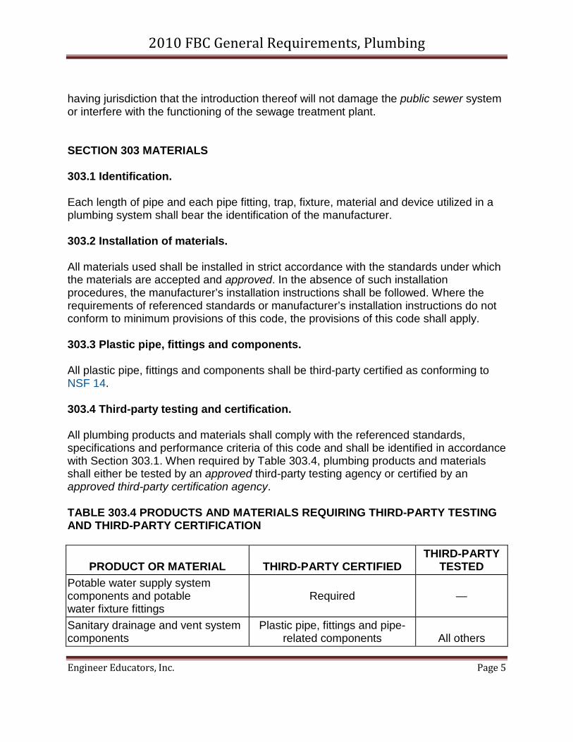
having jurisdiction that the introduction thereof will not damage the public sewer system or interfere with the functioning of the sewage treatment plant. SECTION 303 MATERIALS 303.1 Identification. Each length of pipe and each pipe fitting, trap, fixture, material and device utilized in a plumbing system shall bear the identification of the manufacturer. 303.2 Installation of materials. All materials used shall be installed in strict accordance with the standards under which the materials are accepted and approved. In the absence of such installation procedures, the manufacturer’s installation instructions shall be followed. Where the requirements of referenced standards or manufacturer’s installation instructions do not conform to minimum provisions of this code, the provisions of this code shall apply. 303.3 Plastic pipe, fittings and components. All plastic pipe, fittings and components shall be third-party certified as conforming to NSF 14. 303.4 Third-party testing and certification. All plumbing products and materials shall comply with the referenced standards, specifications and performance criteria of this code and shall be identified in accordance with Section 303.1. When required by Table 303.4, plumbing products and materials shall either be tested by an approved third-party testing agency or certified by an approved third-party certification agency. TABLE 303.4 PRODUCTS AND MATERIALS REQUIRING THIRD-PARTY TESTING AND THIRD-PARTY CERTIFICATION
PRODUCT OR MATERIAL THIRD-PARTY CERTIFIED THIRD-PARTY
TESTED Potable water supply system components and potable water fixture fittings
Required —
Sanitary drainage and vent system components
Plastic pipe, fittings and pipe-related components All others
2010 FBC General Requirements, Plumbing
Engineer Educators, Inc. Page 6
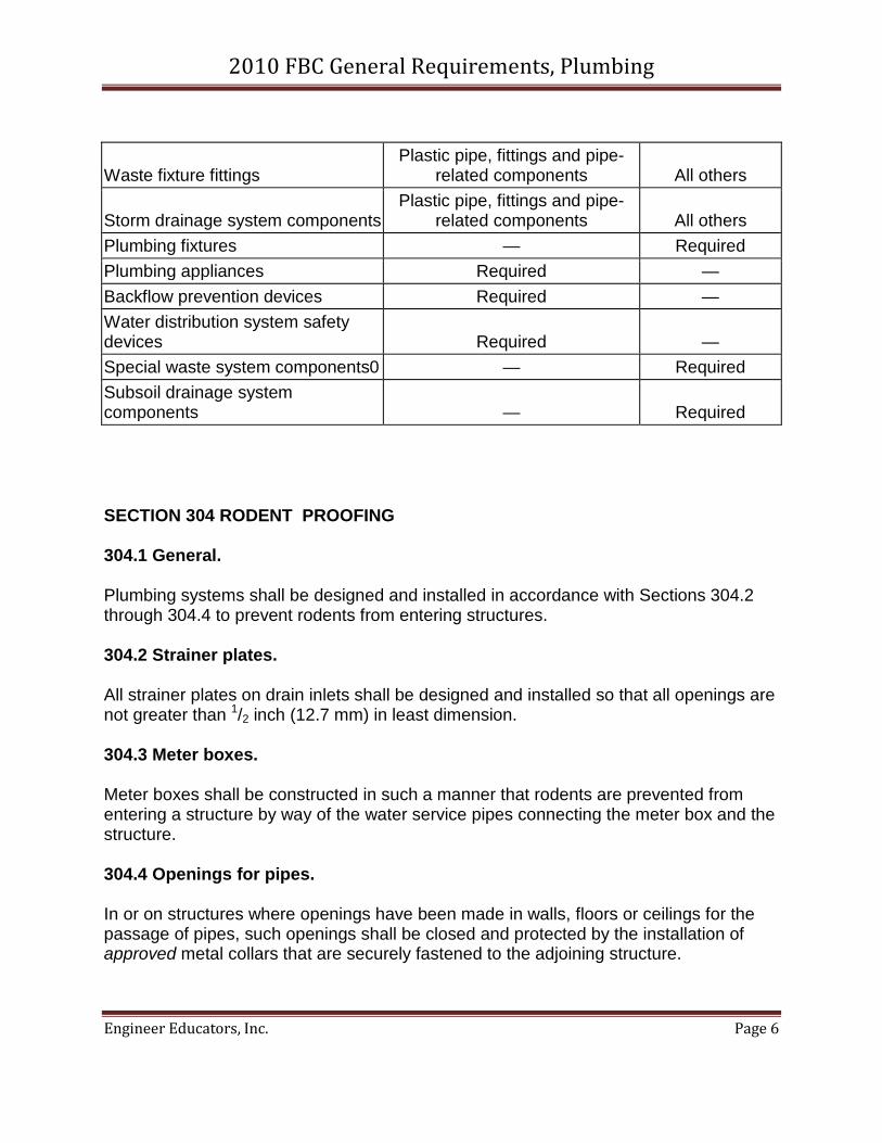
Waste fixture fittings Plastic pipe, fittings and pipe-
related components All others
Storm drainage system components Plastic pipe, fittings and pipe-
related components All others Plumbing fixtures — Required Plumbing appliances Required — Backflow prevention devices Required — Water distribution system safety devices Required — Special waste system components0 — Required Subsoil drainage system components — Required
SECTION 304 RODENT PROOFING 304.1 General. Plumbing systems shall be designed and installed in accordance with Sections 304.2 through 304.4 to prevent rodents from entering structures. 304.2 Strainer plates. All strainer plates on drain inlets shall be designed and installed so that all openings are not greater than 1/2 inch (12.7 mm) in least dimension. 304.3 Meter boxes. Meter boxes shall be constructed in such a manner that rodents are prevented from entering a structure by way of the water service pipes connecting the meter box and the structure. 304.4 Openings for pipes. In or on structures where openings have been made in walls, floors or ceilings for the passage of pipes, such openings shall be closed and protected by the installation of approved metal collars that are securely fastened to the adjoining structure.
2010 FBC General Requirements, Plumbing
Engineer Educators, Inc. Page 7
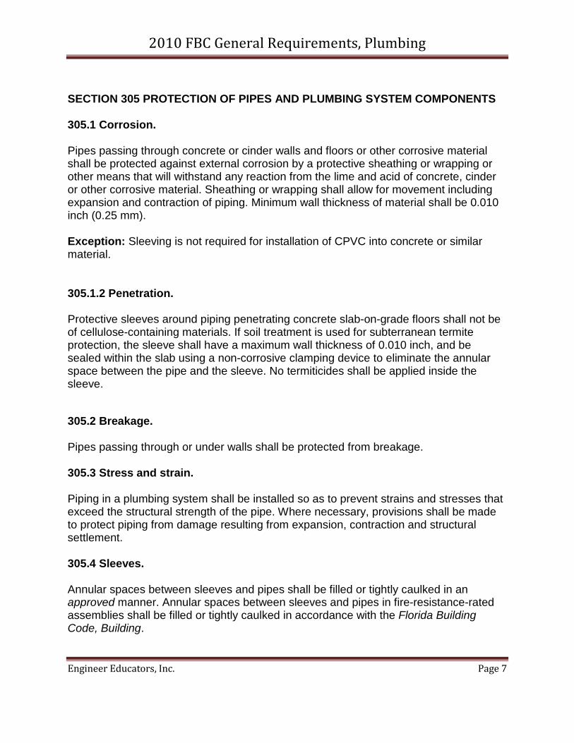
SECTION 305 PROTECTION OF PIPES AND PLUMBING SYSTEM COMPONENTS 305.1 Corrosion. Pipes passing through concrete or cinder walls and floors or other corrosive material shall be protected against external corrosion by a protective sheathing or wrapping or other means that will withstand any reaction from the lime and acid of concrete, cinder or other corrosive material. Sheathing or wrapping shall allow for movement including expansion and contraction of piping. Minimum wall thickness of material shall be 0.010 inch (0.25 mm). Exception: Sleeving is not required for installation of CPVC into concrete or similar material.
305.1.2 Penetration. Protective sleeves around piping penetrating concrete slab-on-grade floors shall not be of cellulose-containing materials. If soil treatment is used for subterranean termite protection, the sleeve shall have a maximum wall thickness of 0.010 inch, and be sealed within the slab using a non-corrosive clamping device to eliminate the annular space between the pipe and the sleeve. No termiticides shall be applied inside the sleeve.
305.2 Breakage. Pipes passing through or under walls shall be protected from breakage. 305.3 Stress and strain. Piping in a plumbing system shall be installed so as to prevent strains and stresses that exceed the structural strength of the pipe. Where necessary, provisions shall be made to protect piping from damage resulting from expansion, contraction and structural settlement. 305.4 Sleeves. Annular spaces between sleeves and pipes shall be filled or tightly caulked in an approved manner. Annular spaces between sleeves and pipes in fire-resistance-rated assemblies shall be filled or tightly caulked in accordance with the Florida Building Code, Building.
2010 FBC General Requirements, Plumbing
Engineer Educators, Inc. Page 8
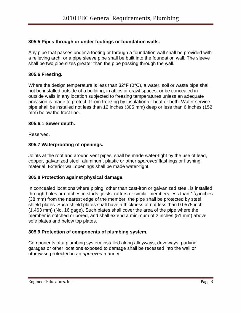
305.5 Pipes through or under footings or foundation walls. Any pipe that passes under a footing or through a foundation wall shall be provided with a relieving arch, or a pipe sleeve pipe shall be built into the foundation wall. The sleeve shall be two pipe sizes greater than the pipe passing through the wall. 305.6 Freezing. Where the design temperature is less than 32°F (0°C), a water, soil or waste pipe shall not be installed outside of a building, in attics or crawl spaces, or be concealed in outside walls in any location subjected to freezing temperatures unless an adequate provision is made to protect it from freezing by insulation or heat or both. Water service pipe shall be installed not less than 12 inches (305 mm) deep or less than 6 inches (152 mm) below the frost line. 305.6.1 Sewer depth. Reserved.
305.7 Waterproofing of openings. Joints at the roof and around vent pipes, shall be made water-tight by the use of lead, copper, galvanized steel, aluminum, plastic or other approved flashings or flashing material. Exterior wall openings shall be made water-tight. 305.8 Protection against physical damage. In concealed locations where piping, other than cast-iron or galvanized steel, is installed through holes or notches in studs, joists, rafters or similar members less than 11/2 inches (38 mm) from the nearest edge of the member, the pipe shall be protected by steel shield plates. Such shield plates shall have a thickness of not less than 0.0575 inch (1.463 mm) (No. 16 gage). Such plates shall cover the area of the pipe where the member is notched or bored, and shall extend a minimum of 2 inches (51 mm) above sole plates and below top plates. 305.9 Protection of components of plumbing system. Components of a plumbing system installed along alleyways, driveways, parking garages or other locations exposed to damage shall be recessed into the wall or otherwise protected in an approved manner.
2010 FBC General Requirements, Plumbing
Engineer Educators, Inc. Page 9
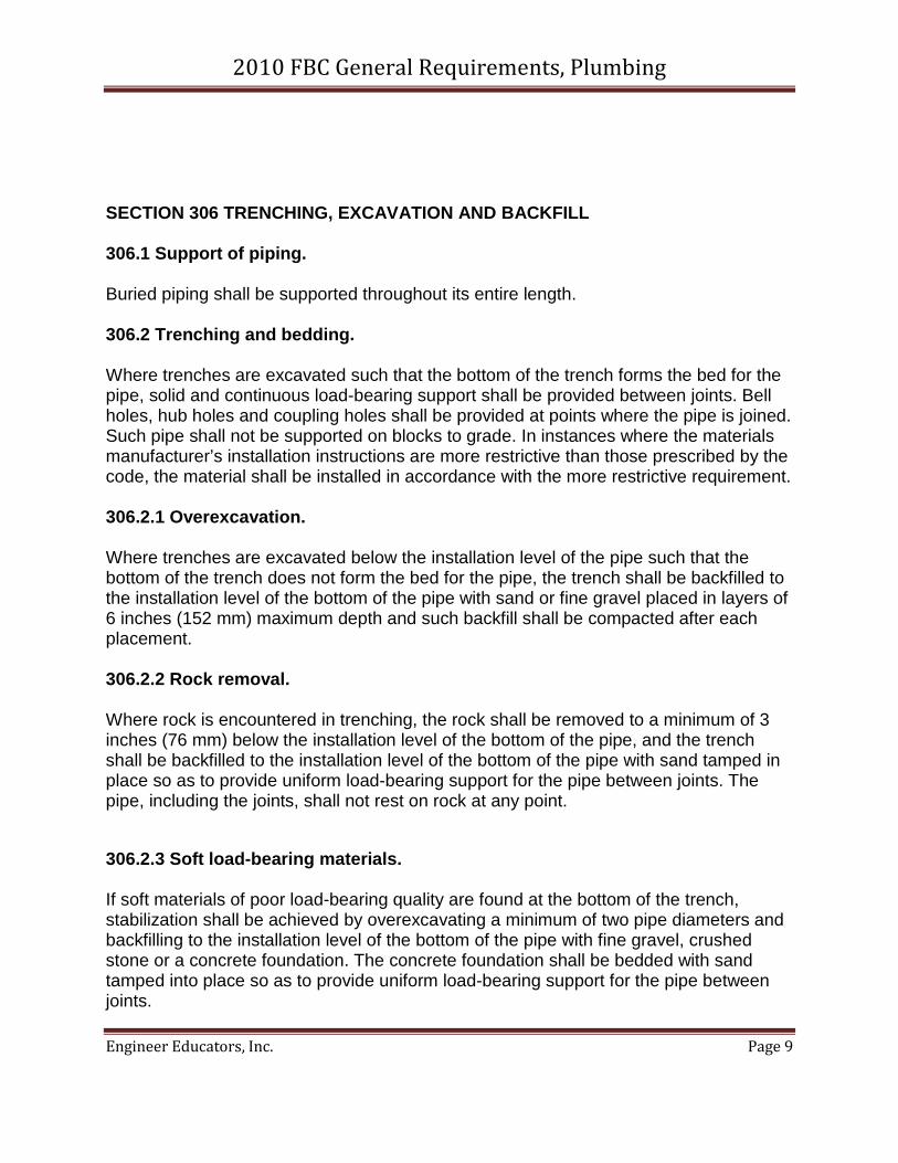
SECTION 306 TRENCHING, EXCAVATION AND BACKFILL 306.1 Support of piping. Buried piping shall be supported throughout its entire length. 306.2 Trenching and bedding. Where trenches are excavated such that the bottom of the trench forms the bed for the pipe, solid and continuous load-bearing support shall be provided between joints. Bell holes, hub holes and coupling holes shall be provided at points where the pipe is joined. Such pipe shall not be supported on blocks to grade. In instances where the materials manufacturer’s installation instructions are more restrictive than those prescribed by the code, the material shall be installed in accordance with the more restrictive requirement. 306.2.1 Overexcavation. Where trenches are excavated below the installation level of the pipe such that the bottom of the trench does not form the bed for the pipe, the trench shall be backfilled to the installation level of the bottom of the pipe with sand or fine gravel placed in layers of 6 inches (152 mm) maximum depth and such backfill shall be compacted after each placement. 306.2.2 Rock removal. Where rock is encountered in trenching, the rock shall be removed to a minimum of 3 inches (76 mm) below the installation level of the bottom of the pipe, and the trench shall be backfilled to the installation level of the bottom of the pipe with sand tamped in place so as to provide uniform load-bearing support for the pipe between joints. The pipe, including the joints, shall not rest on rock at any point.
306.2.3 Soft load-bearing materials. If soft materials of poor load-bearing quality are found at the bottom of the trench, stabilization shall be achieved by overexcavating a minimum of two pipe diameters and backfilling to the installation level of the bottom of the pipe with fine gravel, crushed stone or a concrete foundation. The concrete foundation shall be bedded with sand tamped into place so as to provide uniform load-bearing support for the pipe between joints.
2010 FBC General Requirements, Plumbing
Engineer Educators, Inc. Page 10
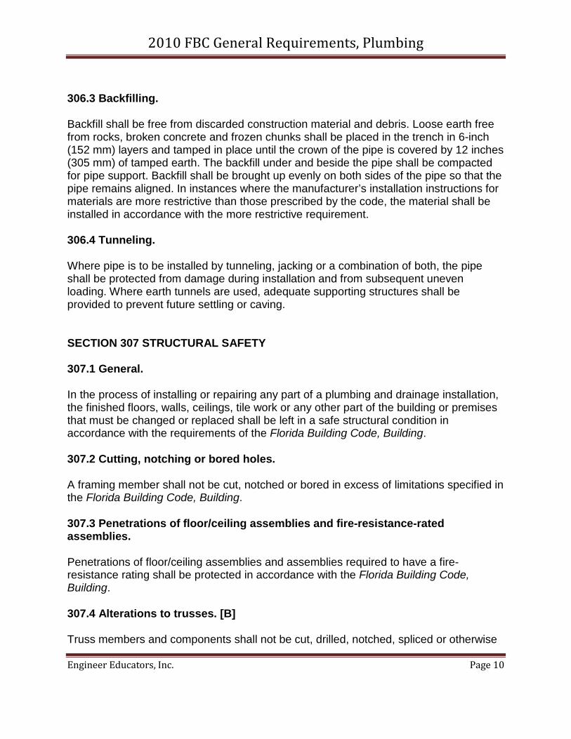
306.3 Backfilling. Backfill shall be free from discarded construction material and debris. Loose earth free from rocks, broken concrete and frozen chunks shall be placed in the trench in 6-inch (152 mm) layers and tamped in place until the crown of the pipe is covered by 12 inches (305 mm) of tamped earth. The backfill under and beside the pipe shall be compacted for pipe support. Backfill shall be brought up evenly on both sides of the pipe so that the pipe remains aligned. In instances where the manufacturer’s installation instructions for materials are more restrictive than those prescribed by the code, the material shall be installed in accordance with the more restrictive requirement. 306.4 Tunneling. Where pipe is to be installed by tunneling, jacking or a combination of both, the pipe shall be protected from damage during installation and from subsequent uneven loading. Where earth tunnels are used, adequate supporting structures shall be provided to prevent future settling or caving. SECTION 307 STRUCTURAL SAFETY 307.1 General. In the process of installing or repairing any part of a plumbing and drainage installation, the finished floors, walls, ceilings, tile work or any other part of the building or premises that must be changed or replaced shall be left in a safe structural condition in accordance with the requirements of the Florida Building Code, Building. 307.2 Cutting, notching or bored holes. A framing member shall not be cut, notched or bored in excess of limitations specified in the Florida Building Code, Building. 307.3 Penetrations of floor/ceiling assemblies and fire-resistance-rated assemblies. Penetrations of floor/ceiling assemblies and assemblies required to have a fire-resistance rating shall be protected in accordance with the Florida Building Code, Building. 307.4 Alterations to trusses. [B] Truss members and components shall not be cut, drilled, notched, spliced or otherwise
2010 FBC General Requirements, Plumbing
Engineer Educators, Inc. Page 11
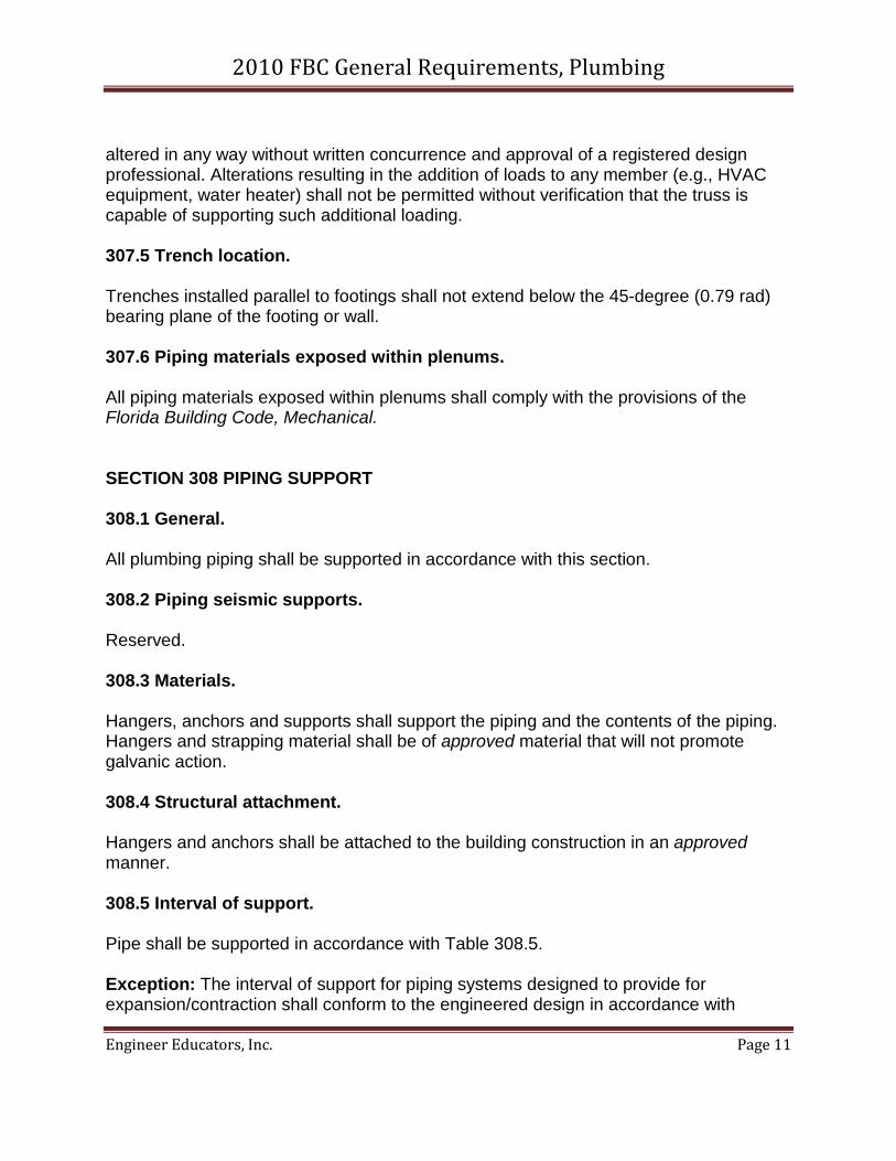
altered in any way without written concurrence and approval of a registered design professional. Alterations resulting in the addition of loads to any member (e.g., HVAC equipment, water heater) shall not be permitted without verification that the truss is capable of supporting such additional loading. 307.5 Trench location. Trenches installed parallel to footings shall not extend below the 45-degree (0.79 rad) bearing plane of the footing or wall. 307.6 Piping materials exposed within plenums. All piping materials exposed within plenums shall comply with the provisions of the Florida Building Code, Mechanical. SECTION 308 PIPING SUPPORT 308.1 General. All plumbing piping shall be supported in accordance with this section. 308.2 Piping seismic supports. Reserved. 308.3 Materials. Hangers, anchors and supports shall support the piping and the contents of the piping. Hangers and strapping material shall be of approved material that will not promote galvanic action. 308.4 Structural attachment. Hangers and anchors shall be attached to the building construction in an approved manner. 308.5 Interval of support. Pipe shall be supported in accordance with Table 308.5. Exception: The interval of support for piping systems designed to provide for expansion/contraction shall conform to the engineered design in accordance with
2010 FBC General Requirements, Plumbing
Engineer Educators, Inc. Page 12
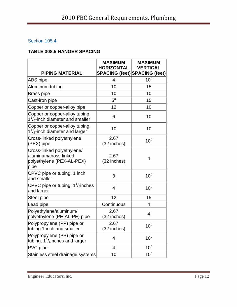
Section 105.4. TABLE 308.5 HANGER SPACING
PIPING MATERIAL
MAXIMUM HORIZONTAL
SPACING (feet)
MAXIMUM VERTICAL
SPACING (feet) ABS pipe 4 10b Aluminum tubing 10 15 Brass pipe 10 10 Cast-iron pipe 5a 15 Copper or copper-alloy pipe 12 10 Copper or copper-alloy tubing, 11/4-inch diameter and smaller 6 10
Copper or copper-alloy tubing, 11/2-inch diameter and larger 10 10
Cross-linked polyethylene (PEX) pipe
2.67 (32 inches) 10b
Cross-linked polyethylene/ aluminum/cross-linked polyethylene (PEX-AL-PEX) pipe
2.67 (32 inches) 4
CPVC pipe or tubing, 1 inch and smaller 3 10b
CPVC pipe or tubing, 11/4inches and larger 4 10b
Steel pipe 12 15 Lead pipe Continuous 4 Polyethylene/aluminum/ polyethylene (PE-AL-PE) pipe
2.67 (32 inches) 4
Polypropylene (PP) pipe or tubing 1 inch and smaller
2.67 (32 inches) 10b
Polypropylene (PP) pipe or tubing, 11/4inches and larger 4 10b
PVC pipe 4 10b Stainless steel drainage systems 10 10b
2010 FBC General Requirements, Plumbing
Engineer Educators, Inc. Page 13
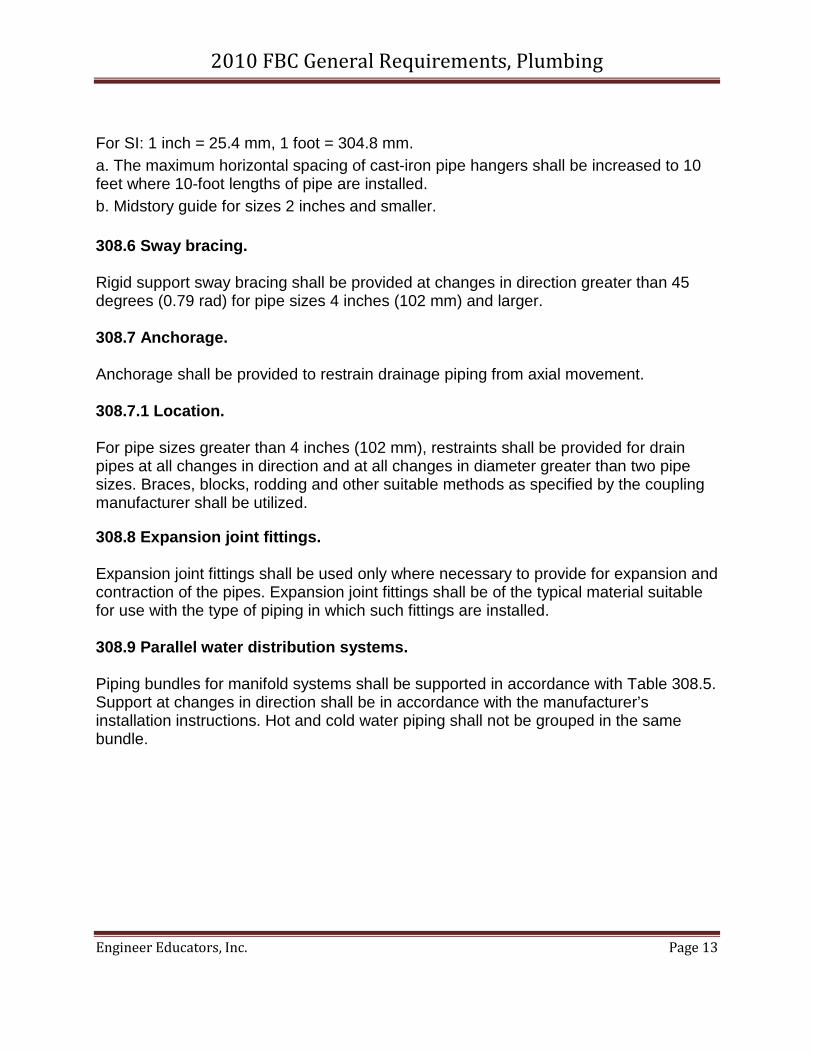
For SI: 1 inch = 25.4 mm, 1 foot = 304.8 mm. a. The maximum horizontal spacing of cast-iron pipe hangers shall be increased to 10 feet where 10-foot lengths of pipe are installed. b. Midstory guide for sizes 2 inches and smaller. 308.6 Sway bracing. Rigid support sway bracing shall be provided at changes in direction greater than 45 degrees (0.79 rad) for pipe sizes 4 inches (102 mm) and larger. 308.7 Anchorage. Anchorage shall be provided to restrain drainage piping from axial movement. 308.7.1 Location. For pipe sizes greater than 4 inches (102 mm), restraints shall be provided for drain pipes at all changes in direction and at all changes in diameter greater than two pipe sizes. Braces, blocks, rodding and other suitable methods as specified by the coupling manufacturer shall be utilized.
308.8 Expansion joint fittings. Expansion joint fittings shall be used only where necessary to provide for expansion and contraction of the pipes. Expansion joint fittings shall be of the typical material suitable for use with the type of piping in which such fittings are installed. 308.9 Parallel water distribution systems. Piping bundles for manifold systems shall be supported in accordance with Table 308.5. Support at changes in direction shall be in accordance with the manufacturer’s installation instructions. Hot and cold water piping shall not be grouped in the same bundle.
2010 FBC General Requirements, Plumbing
Engineer Educators, Inc. Page 14
SECTION 309 FLOOD HAZARD RESISTANCE 309.1 General. Plumbing systems and equipment in structures erected in flood hazard areas shall be constructed in accordance with the requirements of this section and the Florida Building Code, Building. 309.2 Flood hazard. [B] For structures located in flood hazard areas, the following systems and equipment shall be located and installed as required by Section 1612.4 of the Florida Building Code, Building. Exception: The following systems are permitted to be located below the elevation required by Section 1612.4 of the Florida Building Code, Building for utilities and attendant equipment provided that the systems are designed and installed to prevent water from entering or accumulating within their components and the systems are constructed to resist hydrostatic and hydrodynamic loads and stresses, including the effects of buoyancy, during the occurrence of flooding up to the design flood elevation.
1. All water service pipes. 2. Pump seals in individual water supply systems where the pump is located below the design flood elevation. 3. Covers on potable water wells shall be sealed, except where the top of the casing well or pipe sleeve is elevated to at least 1 foot (305 mm) above the design flood elevation. 4. All sanitary drainage piping. 5. All storm drainage piping. 6. Manhole covers shall be sealed, except where elevated to or above the design flood elevation. 7. All other plumbing fixtures, faucets, fixture fittings, piping systems and equipment. 8. Water heaters. 9. Vents and vent systems.
309.3 Flood hazard areas subject to high-velocity wave action. [B] Structures located in flood hazard areas subject to high-velocity wave action shall meet the requirements of Section 309.2. The plumbing systems, pipes and fixtures shall not be mounted on or penetrate through walls intended to break away under flood loads.
2010 FBC General Requirements, Plumbing
Engineer Educators, Inc. Page 15
SECTION 310 WASHROOM AND TOILET ROOM REQUIREMENTS 310.1 Light and ventilation. Washrooms and toilet rooms shall be illuminated and ventilated in accordance with the Florida Building Code, Building and Florida Building Code, Mechanical. 310.2 Location of fixtures and piping. Piping, fixtures or equipment shall not be located in such a manner as to interfere with the normal operation of windows, doors or other means of egress openings. 310.3 Interior finish. Interior finish surfaces of toilet rooms shall comply with the Florida Building Code, Building. 310.4 Water closet compartment. Each water closet utilized by the public or employees shall occupy a separate compartment with walls or partitions and a door enclosing the fixtures to ensure privacy. Exceptions:
1. Water closet compartments shall not be required in a single-occupant toilet room with a lockable door. 2. Toilet rooms located in day care and child-care facilities and containing two or more water closets shall be permitted to have one water closet without an enclosing compartment. 3. This provision is not applicable to toilet areas located within Group I-3 housing areas.
310.5 Urinal partitions. Each urinal utilized by the public or employees shall occupy a separate area with walls or partitions to provide privacy. The walls or partitions shall begin at a height not more than 12 inches (305 mm) from and extend not less than 60 inches (1524 mm) above the finished floor surface. The walls or partitions shall extend from the wall surface at each side of the urinal a minimum of 18 inches (457 mm) or to a point not less than 6 inches (152 mm) beyond the outermost front lip of the urinal measured from the finished back wall surface, whichever is greater.
2010 FBC General Requirements, Plumbing
Engineer Educators, Inc. Page 16
Exceptions:
1. Urinal partitions shall not be required in a single occupant or family/assisted-use toilet room with a lockable door. 2. Toilet rooms located in day-care and child-care facilities and containing two or more urinals shall be permitted to have one urinal without partitions.
SECTION 311 TOILET FACILITIES FOR WORKERS 311.1 General. Toilet facilities shall be provided for construction workers and such facilities shall be maintained in a sanitary condition. Construction worker toilet facilities of the nonsewer type shall conform to ANSI Z4.3. SECTION 312 TESTS AND INSPECTIONS 312.1 Required tests. The permit holder shall make the applicable tests prescribed in Sections 312.2 through 312.10 to determine compliance with the provisions of this code. The permit holder shall give reasonable advance notice to the code official when the plumbing work is ready for tests. The equipment, material, power and labor necessary for the inspection and test shall be furnished by the permit holder and the permit holder shall be responsible for determining that the work will withstand the test pressure prescribed in the following tests. All plumbing system piping shall be tested with either water or, for piping systems other than plastic, by air. After the plumbing fixtures have been set and their traps filled with water, the entire drainage system shall be submitted to final tests. The code official shall require the removal of any cleanouts if necessary to ascertain whether the pressure has reached all parts of the system. 312.1.1 Test gauges. Gauges used for testing shall be as follows:
1. Tests requiring a pressure of 10 pounds per square inch (psi) (69 kPa) or less shall utilize a testing gauge having increments of 0.10 psi (0.69 kPa) or less.
2010 FBC General Requirements, Plumbing
Engineer Educators, Inc. Page 17
2. Tests requiring a pressure of greater than 10 psi (69 kPa) but less than or equal to 100 psi (689 kPa) shall utilize a testing gauge having increments of 1 psi (6.9 kPa) or less. 3. Tests requiring a pressure of greater than 100 psi (689 kPa) shall utilize a testing gauge having increments of 2 psi (14 kPa) or less.
312.2 Drainage and vent water test. A water test shall be applied to the drainage system either in its entirety or in sections. If applied to the entire system, all openings in the piping shall be tightly closed, except the highest opening, and the system shall be filled with water to point of overflow. If the system is tested in sections, each opening shall be tightly plugged except the highest openings of the section under test, and each section shall be filled with water, but no section shall be tested with less than a 5-foot (1524 mm) head of water. In testing successive sections, at least the upper 5 feet (1524 mm) of the next preceding section shall be tested so that no joint or pipe in the building, except the uppermost 5 feet (1524 mm) of the system, shall have been submitted to a test of less than a 5-foot (1524 mm) head of water. The water shall be kept in the system, or in the portion under test, for at least 15 minutes before inspection starts. The system shall then be tight at all points. 312.3 Drainage and vent air test. An air test shall be made by forcing air into the system until there is a uniform gauge pressure of 5 psi (34.5 kPa) or sufficient to balance a 10-inch (254 mm) column of mercury. This pressure shall be held for a test period of at least 15 minutes. Any adjustments to the test pressure required because of changes in ambient temperature or the seating of gaskets shall be made prior to the beginning of the test period. 312.4 Drainage and vent final test. The final test of the completed drainage and vent systems shall be visual and in sufficient detail to determine compliance with the provisions of this code. Where a smoke test is utilized, it shall be made by filling all traps with water and then introducing into the entire system a pungent, thick smoke produced by one or more smoke machines. When the smoke appears at stack openings on the roof, the stack openings shall be closed and a pressure equivalent to a 1-inch water column (248.8 Pa) shall be held for a test period of not less than 15 minutes. 312.5 Water supply system test. Upon completion of a section of or the entire water supply system, the system, or portion completed, shall be tested and proved tight under a water pressure not less than the working pressure of the system; or, for piping systems other than plastic, by an air
2010 FBC General Requirements, Plumbing
Engineer Educators, Inc. Page 18
test of not less than 50 psi (344 kPa). The water utilized for tests shall be obtained from a potable source of supply. The required tests shall be performed in accordance with this section and Section 312 of this code. 312.6 Gravity sewer test. Gravity sewer tests shall consist of plugging the end of the building sewer at the point of connection with the public sewer, completely filling the building sewer with water from the lowest to the highest point thereof, and maintaining such pressure for 15 minutes. The building sewer shall be water tight at all points.
312.7 Forced sewer test. Forced sewer tests shall consist of plugging the end of the building sewer at the point of connection with the public sewer and applying a pressure of 5 psi (34.5 kPa) greater than the pump rating, and maintaining such pressure for 15 minutes. 312.8 Storm drainage system test. Storm drain systems within a building shall be tested by water or air in accordance with Section 312.2 or 312.3. 312.9 Shower liner test. Where shower floors and receptors are made water-tight by the application of materials required by Section 417.5.2, the completed liner installation shall be tested. The pipe from the shower drain shall be plugged water tight for the test. The floor and receptor area shall be filled with potable water to a depth of not less than 2 inches (51 mm) measured at the threshold. Where a threshold of at least 2 inches (51 mm) high does not exist, a temporary threshold shall be constructed to retain the test water in the lined floor or receptor area to a level not less than 2 inches (51 mm) deep measured at the threshold. The water shall be retained for a test period of not less than 15 minutes, and there shall not be evidence of leakage. 312.10 Inspection and testing of backflow prevention assemblies. Inspection and testing shall comply with Sections 312.10.1 and 312.10.2. 312.10.1 Inspections. Inspections shall be made of all backflow prevention assemblies and air gaps to determine whether they are operable.
2010 FBC General Requirements, Plumbing
Engineer Educators, Inc. Page 19
312.10.2 Testing. Reduced pressure principle backflow preventer assemblies, double check-valve assemblies, pressure vacuum breaker assemblies, reduced pressure detector fire protection backflow prevention assemblies, double check detector fire protection backflow prevention assemblies, hose connection backflow preventers, and spill-proof vacuum breakers shall be tested at the time of installation and immediately after repairs or relocation. The testing procedure shall be performed in accordance with one of the following standards: ASSE 5013, ASSE 5015, ASSE 5020, ASSE 5047, ASSE 5048, ASSE 5052, ASSE 5056, CSA B64.10 or CSA B64.10.1.
SECTION 313 EQUIPMENT EFFICIENCIES 313.1 General. Equipment efficiencies shall be in accordance with the Florida Building Code, Energy Conservation. SECTION 314 CONDENSATE DISPOSAL 314.1 Fuel-burning appliances. [M] Liquid combustion by-products of condensing appliances shall be collected and discharged to an approved plumbing fixture or disposal area in accordance with the manufacturer’s installation instructions. Condensate piping shall be of approved corrosion-resistant material and shall not be smaller than the drain connection on the appliance. Such piping shall maintain a minimum horizontal slope in the direction of discharge of not less than one-eighth unit vertical in 12 units horizontal (1-percent slope). 314.2 Evaporators and cooling coils. [M] Condensate drain systems shall be provided for equipment and appliances containing evaporators or cooling coils. Condensate drain systems shall be designed, constructed and installed in accordance with Sections 314.2.1 through 314.2.5. 314.2.1 Condensate disposal. [M]
2010 FBC General Requirements, Plumbing
Engineer Educators, Inc. Page 20
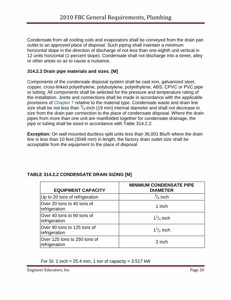
Condensate from all cooling coils and evaporators shall be conveyed from the drain pan outlet to an approved place of disposal. Such piping shall maintain a minimum horizontal slope in the direction of discharge of not less than one-eighth unit vertical in 12 units horizontal (1-percent slope). Condensate shall not discharge into a street, alley or other areas so as to cause a nuisance. 314.2.2 Drain pipe materials and sizes. [M] Components of the condensate disposal system shall be cast iron, galvanized steel, copper, cross-linked polyethylene, polybutylene, polyethylene, ABS, CPVC or PVC pipe or tubing. All components shall be selected for the pressure and temperature rating of the installation. Joints and connections shall be made in accordance with the applicable provisions of Chapter 7 relative to the material type. Condensate waste and drain line size shall be not less than 3/4-inch (19 mm) internal diameter and shall not decrease in size from the drain pan connection to the place of condensate disposal. Where the drain pipes from more than one unit are manifolded together for condensate drainage, the pipe or tubing shall be sized in accordance with Table 314.2.2. Exception: On wall mounted ductless split units less than 36,001 Btu/h where the drain line is less than 10 feet (3048 mm) in length, the factory drain outlet size shall be acceptable from the equipment to the place of disposal.
TABLE 314.2.2 CONDENSATE DRAIN SIZING [M]
EQUIPMENT CAPACITY MINIMUM CONDENSATE PIPE
DIAMETER Up to 20 tons of refrigeration 3/4 inch Over 20 tons to 40 tons of refrigeration 1 inch
Over 40 tons to 90 tons of refrigeration 11/4 inch
Over 90 tons to 125 tons of refrigeration 11/2 inch
Over 125 tons to 250 tons of refrigeration 2 inch
For SI: 1 inch = 25.4 mm, 1 ton of capacity = 3.517 kW
2010 FBC General Requirements, Plumbing
Engineer Educators, Inc. Page 21
. 314.2.3 Auxiliary and secondary drain systems. [M] In addition to the requirements of Section 314.2.1, where damage to any building components could occur as a result of overflow from the equipment primary condensate removal system, one of the following auxiliary protection methods shall be provided for each cooling coil or fuel-fired appliance that produces condensate: 1. An auxiliary drain pan with a separate drain shall be provided under the coils on which condensation will occur. The auxiliary pan drain shall discharge to a conspicuous point of disposal to alert occupants in the event of a stoppage of the primary drain. The pan shall have a minimum depth of 11/2 inches (38 mm), shall not be less than 3 inches (76 mm) larger than the unit or the coil dimensions in width and length and shall be constructed of corrosion-resistant material. Galvanized sheet metal pans shall have a minimum thickness of not less than 0.0236-inch (0.6010 mm) (No. 24 gage) galvanized sheet metal. Nonmetallic pans shall have a minimum thickness of not less than 0.0625 inch (1.6 mm). 2. A separate overflow drain line shall be connected to the drain pan provided with the equipment. Such overflow drain shall discharge to a conspicuous point of disposal to alert occupants in the event of a stoppage of the primary drain. The overflow drain line shall connect to the drain pan at a higher level than the primary drain connection. 3. An auxiliary drain pan without a separate drain line shall be provided under the coils on which condensate will occur. Such pan shall be equipped with a water-level detection device conforming to UL 508 that will shut off the equipment served prior to overflow of the pan. The auxiliary drain pan shall be constructed in accordance with Item 1 of this section. 4. Reserved. 314.2.3.1 Water-level monitoring devices. [M] On down-flow units and all other coils that do not have a secondary drain or provisions to install a secondary or auxiliary drain pan, a water-level monitoring device shall be installed inside the primary drain pan. This device shall shut off the equipment served in the event that the primary drain becomes restricted. Devices installed in the drain line shall not be permitted. 314.2.3.2 Appliance, equipment and insulation in pans. [M] Where appliances, equipment or insulation are subject to water damage when auxiliary drain pans fill such portions of the appliances, equipment and insulation shall be installed above the flood level rim of the pan. Supports located inside of the pan to support the appliance or equipment shall be water resistant and
2010 FBC General Requirements, Plumbing
Engineer Educators, Inc. Page 22
approved. 314.2.4 Traps. [M] Condensate drains shall be trapped as required by the equipment or appliance manufacturer. 314.2.5 Pipe insulation. All horizontal primary condensate drains within unconditioned areas shall be insulated to prevent condensation from forming on the exterior of the drain pipe.
SECTION 315 PUBLIC FOOD SERVICE ESTABLISHMENTS AND FOOD ESTABLISHMENTS 315.1 Requirements. Public food service establishments and food establishments, as defined in Chapter 381 Florida Statutes, Chapter 500 Florida Statutes and Chapter 509 Florida Statutes, shall comply with the applicable code requirements found in the Florida Building Code, Building, Chapter 4, Special Occupancy.
SECTION 316 IRRIGATION 316.1 General. Irrigation/sprinkler systems and risers for spray heads shall not be installed within 1 foot (305 mm) of the building sidewall.
2010 FBC General Requirements, Plumbing
Engineer Educators, Inc. Page 23
Course Exam
One Hour Advanced Internet Course on
Chapter 3 General Regulations of the2010 Florida Building Code: Plumbing, with 2012 Supplements
2010 FBC General Requirements, Plumbing
Engineer Educators, Inc. Page 24
1. All plumbing products and materials shall comply with the referenced standards, specifications and performance criteria of this code and shall be identified in accordance with Section 303.1. Certain plumbing products and materiel must be certified by an approved certification agency. Those products include:
a. Potable water supply components
b. Plumbing appliances
c. Back flow prevention devices
d. All of the above
2. Design Professionals designing plumbing systems for rodent proofing must design all strainer plates on drain inlets so that no opening is greater than:
a 12.7 mm
b 13.0 mm
c 5/8 inch
d 3/8 inch
3. In order to protect pipes passing through concrete or cinder walls they must be protected by a sheathing or wrapping that allows for expansion or contraction and be of thickness not less than:
a. 20 mm
b. .010 inch
c. .025 mm
d. 1/8 inch
2010 FBC General Requirements, Plumbing
Engineer Educators, Inc. Page 25
4. When in the process of installing or repairing any part of the plumbing or drainage installation any part of the building changed or replaced must be left in safe structural condition. Truss members or components can be altered if
a. the alteration is less than 1 ½ inches from the nearest edge of the member
b. the alteration is approved by the approval of the design professional
c. the alteration results in an additional load of 10% or less
d. the alteration is approved by the building inspector.
5. With the exception of systems designed in accordance with Section 105.4 of the code, systems that utilize CDVC pipes of one inch or smaller must provide hanger spacing with maximum horizontal spacing and maximum vertical spacing of
a. 1 meter horizontal / 3 meters vertical
b. 3 feet horizontal / 10 feet vertical
c. 4 feet horizontal / 10 feet vertical
d. 32 inches horizontal / 4 feet vertical
6. The following systems are permitted to be located below the elevation required by Section 1612.4 of the Florida Building Code, Building for utilities and attendant equipment provided that systems are designed and installed to prevent water from entering or accumulating within their components and the systems are constructed to resist hydrostatic and hydrodynamic loads and stresses, including buoyancy, during the occurrence of flooding up to design flood elevation
a. Water service pipes
b. Potable water wells provided the covers are sealed and the top of the casing well or pipe sleeve is 305 mm above the design flood elevation
2010 FBC General Requirements, Plumbing
Engineer Educators, Inc. Page 26
c. Sanitary drainage piping
d. All of the above
7. The following is NOT a requirement of Section 312.2 Drainage and vent water tests.
.a. The water test shall be applied to the drainage systems in its entirety or in sections
b. Tests require a pressure of greater than 10 psi or 0.69 kPa.
c. When testing in section no section may be tested with less than a 5 foot head of water
d. The portion being tested must hold the water at least 15 minutes before inspection begins
8. Except for wall mounted ductless split unites less than 36,001 Btu/h where the drain pipe is less than 10 feet in length and where the drain pipes from more than one unit are molded together the minimum condensate pipe diameter for equipment capcity of between 40 and 90 tons is
a. 2.54 cm
b. 1 inch
c. 1 ¼ inches
d. 3.0 cm
9. In addition to the basic requirements for evaporators and cooling coils there are additional requirements that may be imposed where possible damage to a building may occur as a result of overflow from the primary condensate removal. The additional requirements may include:
a. An auxiliary drain pan with a separate drain
2010 FBC General Requirements, Plumbing
Engineer Educators, Inc. Page 27
b. A separate over low drain line that is connected to the drain pan that is provided with the equipment
c. An auxiliary drain pan without a separate drain line provided the pan is equipped with a water level detection device.
d. Any of the above
10. Test required to insure compliance with the code are the responsibility of:
a. The permit holder
b. the code official
c. the engineer of record
d. the project manager
![[American Society of Plumbing Engineers] Plumbing](https://static.fdocuments.us/doc/165x107/577cb1c91a28aba7118bddeb/american-society-of-plumbing-engineers-plumbing.jpg)